WO2016189662A1 - Catheter for insertion into branched blood vessel - Google Patents
Catheter for insertion into branched blood vessel Download PDFInfo
- Publication number
- WO2016189662A1 WO2016189662A1 PCT/JP2015/065124 JP2015065124W WO2016189662A1 WO 2016189662 A1 WO2016189662 A1 WO 2016189662A1 JP 2015065124 W JP2015065124 W JP 2015065124W WO 2016189662 A1 WO2016189662 A1 WO 2016189662A1
- Authority
- WO
- WIPO (PCT)
- Prior art keywords
- catheter
- distal end
- change point
- property change
- physical property
- Prior art date
Links
Images


Classifications
-
- A—HUMAN NECESSITIES
- A61—MEDICAL OR VETERINARY SCIENCE; HYGIENE
- A61M—DEVICES FOR INTRODUCING MEDIA INTO, OR ONTO, THE BODY; DEVICES FOR TRANSDUCING BODY MEDIA OR FOR TAKING MEDIA FROM THE BODY; DEVICES FOR PRODUCING OR ENDING SLEEP OR STUPOR
- A61M25/00—Catheters; Hollow probes
- A61M25/0043—Catheters; Hollow probes characterised by structural features
- A61M25/005—Catheters; Hollow probes characterised by structural features with embedded materials for reinforcement, e.g. wires, coils, braids
-
- A—HUMAN NECESSITIES
- A61—MEDICAL OR VETERINARY SCIENCE; HYGIENE
- A61M—DEVICES FOR INTRODUCING MEDIA INTO, OR ONTO, THE BODY; DEVICES FOR TRANSDUCING BODY MEDIA OR FOR TAKING MEDIA FROM THE BODY; DEVICES FOR PRODUCING OR ENDING SLEEP OR STUPOR
- A61M25/00—Catheters; Hollow probes
- A61M25/0021—Catheters; Hollow probes characterised by the form of the tubing
- A61M25/0023—Catheters; Hollow probes characterised by the form of the tubing by the form of the lumen, e.g. cross-section, variable diameter
-
- A—HUMAN NECESSITIES
- A61—MEDICAL OR VETERINARY SCIENCE; HYGIENE
- A61M—DEVICES FOR INTRODUCING MEDIA INTO, OR ONTO, THE BODY; DEVICES FOR TRANSDUCING BODY MEDIA OR FOR TAKING MEDIA FROM THE BODY; DEVICES FOR PRODUCING OR ENDING SLEEP OR STUPOR
- A61M25/00—Catheters; Hollow probes
-
- A—HUMAN NECESSITIES
- A61—MEDICAL OR VETERINARY SCIENCE; HYGIENE
- A61M—DEVICES FOR INTRODUCING MEDIA INTO, OR ONTO, THE BODY; DEVICES FOR TRANSDUCING BODY MEDIA OR FOR TAKING MEDIA FROM THE BODY; DEVICES FOR PRODUCING OR ENDING SLEEP OR STUPOR
- A61M25/00—Catheters; Hollow probes
- A61M25/0043—Catheters; Hollow probes characterised by structural features
- A61M25/0045—Catheters; Hollow probes characterised by structural features multi-layered, e.g. coated
-
- A—HUMAN NECESSITIES
- A61—MEDICAL OR VETERINARY SCIENCE; HYGIENE
- A61M—DEVICES FOR INTRODUCING MEDIA INTO, OR ONTO, THE BODY; DEVICES FOR TRANSDUCING BODY MEDIA OR FOR TAKING MEDIA FROM THE BODY; DEVICES FOR PRODUCING OR ENDING SLEEP OR STUPOR
- A61M25/00—Catheters; Hollow probes
- A61M25/0043—Catheters; Hollow probes characterised by structural features
- A61M25/005—Catheters; Hollow probes characterised by structural features with embedded materials for reinforcement, e.g. wires, coils, braids
- A61M25/0053—Catheters; Hollow probes characterised by structural features with embedded materials for reinforcement, e.g. wires, coils, braids having a variable stiffness along the longitudinal axis, e.g. by varying the pitch of the coil or braid
-
- A—HUMAN NECESSITIES
- A61—MEDICAL OR VETERINARY SCIENCE; HYGIENE
- A61M—DEVICES FOR INTRODUCING MEDIA INTO, OR ONTO, THE BODY; DEVICES FOR TRANSDUCING BODY MEDIA OR FOR TAKING MEDIA FROM THE BODY; DEVICES FOR PRODUCING OR ENDING SLEEP OR STUPOR
- A61M25/00—Catheters; Hollow probes
- A61M25/0043—Catheters; Hollow probes characterised by structural features
- A61M25/0054—Catheters; Hollow probes characterised by structural features with regions for increasing flexibility
-
- A—HUMAN NECESSITIES
- A61—MEDICAL OR VETERINARY SCIENCE; HYGIENE
- A61M—DEVICES FOR INTRODUCING MEDIA INTO, OR ONTO, THE BODY; DEVICES FOR TRANSDUCING BODY MEDIA OR FOR TAKING MEDIA FROM THE BODY; DEVICES FOR PRODUCING OR ENDING SLEEP OR STUPOR
- A61M25/00—Catheters; Hollow probes
- A61M25/01—Introducing, guiding, advancing, emplacing or holding catheters
- A61M25/0105—Steering means as part of the catheter or advancing means; Markers for positioning
- A61M25/0108—Steering means as part of the catheter or advancing means; Markers for positioning using radio-opaque or ultrasound markers
-
- A—HUMAN NECESSITIES
- A61—MEDICAL OR VETERINARY SCIENCE; HYGIENE
- A61M—DEVICES FOR INTRODUCING MEDIA INTO, OR ONTO, THE BODY; DEVICES FOR TRANSDUCING BODY MEDIA OR FOR TAKING MEDIA FROM THE BODY; DEVICES FOR PRODUCING OR ENDING SLEEP OR STUPOR
- A61M25/00—Catheters; Hollow probes
- A61M25/01—Introducing, guiding, advancing, emplacing or holding catheters
- A61M25/09—Guide wires
-
- A—HUMAN NECESSITIES
- A61—MEDICAL OR VETERINARY SCIENCE; HYGIENE
- A61M—DEVICES FOR INTRODUCING MEDIA INTO, OR ONTO, THE BODY; DEVICES FOR TRANSDUCING BODY MEDIA OR FOR TAKING MEDIA FROM THE BODY; DEVICES FOR PRODUCING OR ENDING SLEEP OR STUPOR
- A61M25/00—Catheters; Hollow probes
- A61M25/0021—Catheters; Hollow probes characterised by the form of the tubing
- A61M2025/0042—Microcatheters, cannula or the like having outside diameters around 1 mm or less
-
- A—HUMAN NECESSITIES
- A61—MEDICAL OR VETERINARY SCIENCE; HYGIENE
- A61M—DEVICES FOR INTRODUCING MEDIA INTO, OR ONTO, THE BODY; DEVICES FOR TRANSDUCING BODY MEDIA OR FOR TAKING MEDIA FROM THE BODY; DEVICES FOR PRODUCING OR ENDING SLEEP OR STUPOR
- A61M25/00—Catheters; Hollow probes
- A61M25/0043—Catheters; Hollow probes characterised by structural features
- A61M25/0045—Catheters; Hollow probes characterised by structural features multi-layered, e.g. coated
- A61M2025/0046—Coatings for improving slidability
- A61M2025/0047—Coatings for improving slidability the inner layer having a higher lubricity
-
- A—HUMAN NECESSITIES
- A61—MEDICAL OR VETERINARY SCIENCE; HYGIENE
- A61M—DEVICES FOR INTRODUCING MEDIA INTO, OR ONTO, THE BODY; DEVICES FOR TRANSDUCING BODY MEDIA OR FOR TAKING MEDIA FROM THE BODY; DEVICES FOR PRODUCING OR ENDING SLEEP OR STUPOR
- A61M25/00—Catheters; Hollow probes
- A61M25/0043—Catheters; Hollow probes characterised by structural features
- A61M2025/0059—Catheters; Hollow probes characterised by structural features having means for preventing the catheter, sheath or lumens from collapsing due to outer forces, e.g. compressing forces, or caused by twisting or kinking
-
- A—HUMAN NECESSITIES
- A61—MEDICAL OR VETERINARY SCIENCE; HYGIENE
- A61M—DEVICES FOR INTRODUCING MEDIA INTO, OR ONTO, THE BODY; DEVICES FOR TRANSDUCING BODY MEDIA OR FOR TAKING MEDIA FROM THE BODY; DEVICES FOR PRODUCING OR ENDING SLEEP OR STUPOR
- A61M25/00—Catheters; Hollow probes
- A61M25/01—Introducing, guiding, advancing, emplacing or holding catheters
- A61M25/06—Body-piercing guide needles or the like
- A61M25/0662—Guide tubes
- A61M2025/0681—Systems with catheter and outer tubing, e.g. sheath, sleeve or guide tube
-
- A—HUMAN NECESSITIES
- A61—MEDICAL OR VETERINARY SCIENCE; HYGIENE
- A61M—DEVICES FOR INTRODUCING MEDIA INTO, OR ONTO, THE BODY; DEVICES FOR TRANSDUCING BODY MEDIA OR FOR TAKING MEDIA FROM THE BODY; DEVICES FOR PRODUCING OR ENDING SLEEP OR STUPOR
- A61M2205/00—General characteristics of the apparatus
- A61M2205/02—General characteristics of the apparatus characterised by a particular materials
- A61M2205/0216—Materials providing elastic properties, e.g. for facilitating deformation and avoid breaking
-
- A—HUMAN NECESSITIES
- A61—MEDICAL OR VETERINARY SCIENCE; HYGIENE
- A61M—DEVICES FOR INTRODUCING MEDIA INTO, OR ONTO, THE BODY; DEVICES FOR TRANSDUCING BODY MEDIA OR FOR TAKING MEDIA FROM THE BODY; DEVICES FOR PRODUCING OR ENDING SLEEP OR STUPOR
- A61M2210/00—Anatomical parts of the body
- A61M2210/10—Trunk
- A61M2210/1042—Alimentary tract
- A61M2210/1071—Liver; Hepar
-
- A—HUMAN NECESSITIES
- A61—MEDICAL OR VETERINARY SCIENCE; HYGIENE
- A61M—DEVICES FOR INTRODUCING MEDIA INTO, OR ONTO, THE BODY; DEVICES FOR TRANSDUCING BODY MEDIA OR FOR TAKING MEDIA FROM THE BODY; DEVICES FOR PRODUCING OR ENDING SLEEP OR STUPOR
- A61M25/00—Catheters; Hollow probes
- A61M25/0009—Making of catheters or other medical or surgical tubes
- A61M25/0012—Making of catheters or other medical or surgical tubes with embedded structures, e.g. coils, braids, meshes, strands or radiopaque coils
-
- A—HUMAN NECESSITIES
- A61—MEDICAL OR VETERINARY SCIENCE; HYGIENE
- A61M—DEVICES FOR INTRODUCING MEDIA INTO, OR ONTO, THE BODY; DEVICES FOR TRANSDUCING BODY MEDIA OR FOR TAKING MEDIA FROM THE BODY; DEVICES FOR PRODUCING OR ENDING SLEEP OR STUPOR
- A61M25/00—Catheters; Hollow probes
- A61M25/0021—Catheters; Hollow probes characterised by the form of the tubing
- A61M25/0041—Catheters; Hollow probes characterised by the form of the tubing pre-formed, e.g. specially adapted to fit with the anatomy of body channels
Definitions
- the present invention relates to a branched blood vessel insertion catheter for inserting into a small branch blood vessel branched from a mother blood vessel from the mother blood vessel.
- a catheter In the treatment of lesions using a catheter, for example, in the treatment of a liver, it may be required to insert the catheter into a small branched blood vessel that branches off from the mother blood vessel (liver artery).
- a procedure is performed in which a catheter is introduced along a guide wire that is inserted into a mother blood vessel and has a distal end reaching the branch blood vessel, and the distal end is inserted into the branch blood vessel.
- the distal end portion of the guide wire inserted into the branch vessel may be detached from the branch vessel due to the rigidity of the distal end portion of the catheter. It was.
- An object of the present invention is to insert the distal end of a catheter into a branch blood vessel along the guide wire inserted into the mother blood vessel and having the distal end reached the branch blood vessel.
- a branch blood vessel insertion catheter that can easily and surely insert the distal end portion of the catheter into the branch blood vessel without detachment from the branch blood vessel.
- a branched blood vessel insertion catheter for inserting the first blood vessel and the branched blood vessel branched from the first blood vessel into the branched blood vessel through the branch from the first blood vessel,
- a catheter body having a lumen communicating from a distal end to a proximal end for insertion of a guide wire, the catheter body comprising an inner layer, a wire winding reinforcement provided on an outer surface of the inner layer, the inner layer, and the inner layer;
- An outer layer covering the reinforcing body, and the catheter body includes a first physical property change point located at 3.0 to 7.0 mm from the distal end of the catheter, and before and after the first physical property change point.
- a branch vessel insertion catheter having a proximal end side that is higher in rigidity than the distal end side.
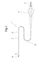
- FIG. 1 is a partially omitted external view showing a state in which a guide wire is inserted through a branch vessel insertion catheter according to an embodiment of the present invention.
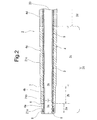
- FIG. 2 is an enlarged cross-sectional view of a distal end portion of the branch vessel insertion catheter shown in FIG.
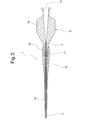
- FIG. 3 is an enlarged cross-sectional view of a proximal end portion of the branch vessel insertion catheter shown in FIG.
- FIG. 4 is a partially omitted external view showing a state in which a guide wire is inserted through a branch vessel insertion catheter according to another embodiment of the present invention.
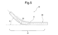
- FIG. 5 is an enlarged external view of the distal end portion of the branch vessel insertion catheter shown in FIG. FIG.
- FIG. 6 is an explanatory view for explaining the action of the branch vessel insertion catheter of the present invention.
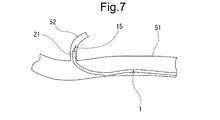
- FIG. 7 is an explanatory view for explaining the operation of the branch vessel insertion catheter of the present invention.
- FIG. 8 is an explanatory diagram for explaining the operation of a conventional branch vessel insertion catheter.
- the catheter of the present invention will be described with reference to the embodiments shown in the drawings.
- the branch blood vessel insertion catheter of the present invention is inserted into the branch blood vessel 52 through the first blood vessel 51 and the small branch blood vessel 52 branched from the first blood vessel 51 through the branch.
- This is a bifurcated blood vessel insertion catheter.
- the branch vessel insertion catheter 1 has a catheter body 2 having a lumen 20 communicating from the distal end to the proximal end for insertion of a guide wire 15.
- the catheter body 2 is provided on the inner layer 3 and the outer surface of the inner layer 3.
- the wire wound reinforcing body 5 and the inner layer 3 and the outer layer 4 covering the reinforcing body 5 are provided.
- the catheter body 2 includes a first physical property change point 6 located 3.0 to 7.0 mm from the distal end of the catheter 1, and the proximal end side is more rigid than the distal end side before and after the first physical property change point 6. Is expensive. An easy-bending portion is formed by the first physical property change point 6 portion.
- the branch vessel insertion catheter 1 of the present invention branches from a first blood vessel (hepatic artery) into a first blood vessel (for example, a hepatic artery) and a narrow branch blood vessel that branches from the first blood vessel (hepatic artery). It is a catheter for branch blood vessel insertion for passing through and inserting into a branch blood vessel.
- the bifurcated blood vessel insertion catheter 1 of the present invention is particularly effective when applied to a microcatheter having an outer diameter of the tip of 1.0 mm or less. Furthermore, it is more effective when applied to a microcatheter having an outer diameter of 0.7 mm or less.
- the branch vessel insertion catheter 1 includes a catheter body 2 having a lumen 20 penetrating from the distal end to the proximal end, and a hub 11 fixed to the proximal end of the catheter body 2.
- the catheter body 2 includes an inner layer 3, a wire-wrapped reinforcing body 5 provided on the outer surface of the inner layer 3, and an outer layer 4 that covers the inner layer 3 and the reinforcing body 5.
- the catheter body 2 includes a first physical property change point 6 located 3.0 to 7.0 mm from the distal end of the catheter 1, and the proximal end side is more rigid than the distal end side before and after the first physical property change point 6.
- a bendable part is formed at the site of the catheter body 2 located before and after the first physical property change point 6.
- the easy bending portion is a portion that tends to be the center of bending compared to before and after the first physical property change point 6.
- the easy bending portion means not a bending point but a region that is easily bent and formed before and after the first physical property change point 6.
- the catheter 1 In having such an easily bendable portion, when the distal end surface or the distal side portion of the catheter 1 comes into contact with the inner wall of the blood vessel in a state where the guide wire having the distal end entered the branch blood vessel is inserted through the catheter, the catheter 1 Is bent at the first physical property change point 6 located 3.0 to 7.0 mm from the distal end, so that the distal end of the catheter 1 jumps and leaves the distal end portion of the guide wire that has entered the branch blood vessel. I will not let you.
- the wire wound reinforcing body 5 has a first winding extending from the distal end of the catheter body 2 to the proximal end side beyond the first physical property change point 6.
- the outer layer 4 extends from the distal end of the catheter body 2 and includes a first resin forming portion 4a formed of the first resin, and the proximal end of the first resin forming portion 4a.
- a second resin forming portion 4b is provided that extends to the base end side and is formed of a second resin that is harder than the first resin.
- the 1st physical property change point 6 is formed of the boundary part of the 1st resin formation part 4a and the 2nd resin formation part 4b. Therefore, the boundary portion is located at 3.0 to 7.0 mm from the distal end of the catheter 1. In particular, the boundary portion is preferably located at 4.0 to 6.0 mm, more preferably 4.5 to 5.5 mm from the distal end of the catheter 1.
- the catheter body 2 will be specifically described.
- the catheter body 2 includes a distal end portion 21 and a main body portion 22.
- the catheter body 2 includes an inner layer 3 that extends throughout, an outer layer 4, and a reinforcing body 5.
- the inner layer 3 forms the inner lumen 20 for inserting the guide wire and the inner surface of the catheter body 2, and is made of substantially the same thickness from the distal end to the proximal end by the same material. It extends.
- the inner layer 3 includes a tip end inner diameter portion 3a extending from the tip to a portion slightly exceeding the first physical property change point 6, and a tip end inner diameter taper portion 3b extending from the base end of the tip end inner diameter portion 3a to the base end side by a predetermined length. And a base end side same inner diameter portion extending from the base end to the base end of the tip end inner diameter tapered portion 3b with substantially the same outer diameter.
- the inner diameter portion 3a having the same inner diameter at the tip of the inner layer 3 preferably has an inner diameter of 0.35 to 0.50 mm, particularly preferably 0.40 mm to 0.46 mm.
- the axial length of the inner diameter portion 3a of the inner layer 3 is preferably 5 to 10 mm
- the proximal end of the inner diameter portion 3a of the inner layer 3 has a base end from the first physical property change point 6. It is preferably located on the base end side of 0 to 4.0 mm.
- the inner diameter taper portion 3b on the distal end side of the inner layer 3 has an inner diameter at the distal end substantially equal to the inner diameter portion 3a with the same distal end, and an inner diameter at the proximal end of 0.53 to 0.65 mm, and is gentle toward the proximal end from the distal end.
- the diameter is preferably increased in a tapered shape.
- the axial length of the inner diameter side tapered portion 3b of the inner layer 3 is preferably about 60 to 200 mm, and more preferably 70 to 150 mm.
- the thickness of the inner layer 3 is preferably about 0.003 to 0.1 mm, and more preferably 0.005 to 0.05 mm.
- the inner layer 3 is formed from the same material to the proximal end.
- a material for forming the inner layer 3 fluororesins such as PTFE and ETFE, polyimide, polyester (for example, polyethylene terephthalate, polybutylene terephthalate), polyolefin (for example, ultra-high molecular polyethylene, polypropylene), polyamide, polyimide, modified polyethylene ether polyamide Rigid resins such as imide, polyetherimide, polystyrene sulfide, and liquid crystal polymer) are preferable.
- fluorine-based polymers such as PTFE and ETFE that can form a low friction inner surface are preferable.
- the wire wound reinforcing body 5 is formed by winding a wire around the outer surface of the inner layer 3.
- the wire-wound reinforcement 5 is preferably one that is wound around the outer surface of the inner layer in a mesh shape or a spiral shape with a thin wire made of a metal wire.
- the wire wound reinforcing body 5 is preferably constituted by a mesh braid (blade) in which thin wires are interwoven.
- a plurality of small-diameter wires wound in the first spiral direction at intervals in the axial direction of the inner layer 3, and the first spiral direction at intervals in the axial direction of the inner layer 3; is preferably a braid formed by crossing a plurality of small-diameter wires wound in different second spiral directions.
- a metal wire is suitable, for example, an X-ray contrasting metal wire such as stainless steel wire, amorphous alloy wire, platinum, gold, tungsten, tantalum, iridium, etc. is preferred.
- an amorphous alloy wire an amorphous alloy wire formed using an iron-silicon-boron alloy, a cobalt-silicon-boron alloy, an iron-cobalt-chromium-molybdenum-silicon-boron alloy, or the like is preferable.
- Tungsten is suitable as the X-ray contrast metal wire.
- a wire having a wire diameter of about 0.01 to 0.05 mm is preferable.
- the wire winding reinforcement body 5 includes a first winding condition portion extending from the distal end of the catheter body 2 to the proximal end side beyond the first physical property change point 6.
- the first winding condition portion extends in the proximal direction beyond a second property change point 7 described later.
- the wire to be used, the winding pitch of a wire, and the winding form of a wire are the same.
- the first winding condition portion exceeds the third resin forming portion 4d extending from the proximal end of the second resin forming portion 4c of the catheter to the proximal end side, and further, the proximal end. It extends to the side.
- the wire winding pitch in the first winding condition portion is preferably 0.2 to 0.8 mm, and particularly preferably 0.3 to 0.6 mm.
- the outer layer 4 extends from the distal end to the proximal end of the catheter body to form the outer surface form of the catheter body.
- the catheter body 2 has the same outer diameter portion 2a extending from the tip to the first physical property change point 6 and an outer diameter larger than the same outer diameter portion 2a (in other words, thicker in thickness), A second distal end identical outer diameter portion 2b extending from the proximal end of the distal end identical outer diameter portion 2a to a predetermined length proximal end side is provided.
- the 1st physical-property change point 6 is formed of the boundary part of the 1st resin formation part 4a and the 2nd resin formation part 4b.
- This boundary part is also an outer diameter changing part.
- the first physical property change point 6 is formed by a change in outer diameter and a difference in hardness of the forming material.
- the first physical property change point 6 is located at 3.0 to 7.0 mm from the distal end of the catheter 1.
- the three-point bending load of the proximal end portion 21b (second identical outer diameter portion 2b) of the catheter near the first physical property change point 6 is 3 of the distal end side portion 21a (the same outer diameter portion 2a of the distal end portion). It is preferably 1.5 to 2.5 times the point bending load. In particular, it is preferably 1.7 to 2.3 times.
- the “three-point bending load” here can be measured as follows. A measuring tool comprising a jig having a horizontal placement surface with a gap of 3 mm that opens upward, and a presser having a linear portion extending in the horizontal direction at the distal end portion, formed of a wire having a wire diameter of 0.85 mm Prepare.
- the catheter is placed on the horizontal placement surface of the jig so as to pass above the gap, and the measurement target part is positioned in the gap.
- the “three-point bending load” is obtained when the measurement target part is pushed into the measurement target part at a speed of 5 mm / min and 0.3 mm by a linear part extending in the horizontal direction from above (the measurement target part). Can be obtained by measuring the load).
- the three-point bending load of the tip side portion 21a near the first physical property change point 6 is preferably 8 to 15 gf, and particularly preferably 9 to 13 gf. Further, the three-point bending load of the proximal end portion 21b in the vicinity of the first physical property change point 6 is preferably 16 to 25 gf, and particularly preferably 18 to 23 gf.
- the three-point bending load at the first physical property change point 6 is preferably near the median value of the three-point bending load of the distal end portion 21a and the three-point bending load of the proximal end portion 21b. Specifically, the three-point bending load at the first physical property change point 6 is preferably 12 to 18 gf.
- the first physical property change point 6 has an axial length of 2.0 mm or less, and has a gradually increasing rigidity toward the base end side.
- the first physical property change point 6 preferably has an axial length of 0.5 to 2.0 mm, and more preferably 0.5 to 1.5 mm.
- the outer diameter of the first distal end portion identical outer diameter portion 2a of the catheter body 2 is preferably 0.50 to 0.65 mm, and particularly preferably 0.52 mm to 0.62 mm.
- the axial length of the first distal end portion identical outer diameter portion 2a of the catheter body 2 is preferably 3.0 to 7.0 mm, more preferably 4.0 to 6.0 mm, and more preferably Preferably, it is 4.5 to 5.5 mm.
- the wall thickness of the first tip portion and the same outer diameter portion 2a is preferably about 0.1 to 0.2 mm.
- the outer diameter of the second distal end identical outer diameter portion 2b of the catheter body 2 is preferably 0.55 to 0.70 mm, particularly preferably 0.57 mm to 0.65 mm. Further, the second tip end same outer diameter portion 2b is preferably 0.01 to 0.07 mm larger than the first tip end same outer diameter portion 2a, and particularly 0.02 to 0.05 mm. Larger is preferred.
- the wall thickness of the second tip portion identical outer diameter portion 2b is preferably about 0.05 to 0.15 mm. Moreover, it is preferable that the thickness of the 2nd front-end
- the axial length of the second tip end same outer diameter portion 2b is preferably 5.0 to 15.0 mm, and particularly preferably 7.0 to 13.0 mm.
- the second resin one having a higher hardness than the first resin is used.
- the first resin and the second resin are preferably different in hardness difference (for example, flexural modulus ASTM D790) by 4 to 15 MPa, and particularly preferably 5 to 10 MPa.
- the catheter body 2 includes the second physical property change point 7 located at 12.0 to 18.0 mm from the distal end of the catheter 1, and before and after the second physical property change point 7.
- the proximal end side has higher rigidity than the distal end side, and the second easily bent portion is formed before and after the second property change point 7.
- the second physical property change point 7 is located closer to the base end side than the first physical property change point 6.
- the second easily bent portion is a portion that tends to be the center of bending compared to before and after the second property change point 7.
- the second easily bent portion means not a bending point but a region that is easily bent and formed before and after the second physical property change point 7.
- the catheter 1 By having the second physical property change point 7 as described above, the proximal end side of the first physical property change point 6 of the catheter 1 in the state where the guide wire whose distal end has entered the small-diameter branch blood vessel is inserted through the catheter.
- the catheter 1 When the adjacent portion comes into contact with the inner wall of the blood vessel (for example, in the vicinity of the portion facing the blood vessel bifurcation), the catheter 1 is in close proximity to the first physical property change point 6 and the second physical property located on the proximal end side. Since it bends at the change point, it becomes easy to point the tip of the catheter 1 toward the blood vessel bifurcation, and after the tip of the catheter 1 enters the branch blood vessel, its state is secured. It becomes.
- the outer layer 4 has the second resin forming portion 4b formed of the above-described second resin.
- the catheter body 2 has a starting end having an outer diameter larger than that of the second distal end portion and the same outer diameter portion 2b, and has a larger outer diameter than the second distal end portion and the same outer diameter portion 2b.
- a distal end outer diameter taper portion 2c is provided that extends to the proximal end side by a predetermined length from (the proximal end of the second distal end same outer diameter portion 2b).
- the second physical property change point 7 has an axial length of 2.0 mm or less and has a gradually increasing rigidity from the distal end side toward the proximal end side.
- the second physical property change point 7 preferably has an axial length of 0.5 to 2.0 mm, and more preferably 0.5 to 1.5 mm.
- the distal end portion 21 of the catheter body 2 is located after the first distal end portion same outer diameter portion 2a and the first distal end portion same outer diameter portion 2a.
- a second distal end identical outer diameter portion 2b extending from the end in the proximal direction and having a larger diameter than the first distal end identical outer diameter portion 2a, and a rear end of the second distal end identical outer diameter portion 2b.
- a distal end side outer diameter taper portion 2c extending in the end direction and having a starting end larger than the second distal end same outer diameter portion 2b is provided.
- the first physical property change point 6 is located at the boundary between the first tip end same outer diameter portion 2a and the second tip end same outer diameter portion 2b, and the second physical property change point 7 is 2 is located at the boundary between the tip end outer diameter portion 2b and the tip end outer diameter taper portion 2c.
- the outer layer 4 includes a distal-end-side outer diameter taper portion 2c formed in the second resin forming portion 4b, and the second physical property change point 7 is formed by the start end of the enlarged-diameter portion. Yes.
- the difference in outer diameter before and after the second physical property change point 7 is preferably 0.02 to 0.05 mm.
- the three-point bending load of the proximal end portion 21c in the vicinity of the second property change point 7 is the distal end portion in the vicinity of the second property change point 7 (the proximal end portion in the vicinity of the first property change point 6). It is preferably 1.15 to 1.8 times the three-point bending load of 21b. In particular, it is preferably 1.2 to 1.6 times.
- the three-point bending load of the proximal end portion 21c near the second physical property change point 7 is preferably 20 to 45 gf, and particularly preferably 22 to 35 gf. Further, the three-point bending load of the tip end portion 21b in the vicinity of the second physical property change point 7 is preferably 16 to 25 gf, and particularly preferably 18 to 23 gf.
- the three-point bending load at the second property change point 7 is preferably near the median value of the three-point bending load of the distal end portion 21b and the three-point bending load of the proximal end portion 21c. Specifically, the three-point bending load at the second property change point 6 is preferably 20 to 26 gf.
- the second physical property change point 7 (in other words, the enlarged diameter portion) is located at 12.0 to 18.0 mm from the distal end of the catheter 1.
- the second physical property change point 7 (expanded portion) is preferably located at 13.0 to 17.0 mm from the distal end of the catheter 1.
- the second physical property change point 7 (expanded diameter portion) is preferably located 7.0 to 13.0 mm proximal to the first physical property change point 6. In particular, it is preferably located on the base end side of 9.0 to 11.0 mm.
- the distal end outer diameter taper portion 2c of the catheter body 2 has an outer diameter of 0.60 to 0.70 mm at the start end, and expands in a gentle taper shape from the start end to the base end. Is preferred.
- the outer diameter of the leading end of the outer diameter taper portion 2c on the distal end side is preferably 0.02 to 0.07 mm larger than the outer diameter (the outer diameter of the proximal end) of the same outer diameter portion 2b of the second distal end. In particular, it is preferably 0.03 to 0.06 mm larger.
- the thickness of the starting end of the distal end side outer diameter tapered portion 2c is preferably about 0.07 to 0.17 mm, and particularly preferably 0.08 to 0.14.
- the thickness of the distal end side outer diameter tapered portion 2c is preferably 0.005 mm or more thicker than the thickness of the second distal end same outer diameter portion 2b.
- the axial length of the distal end side outer diameter tapered portion 2c is preferably 30 to 100 mm, and particularly preferably 40 to 80 mm. Further, it is preferable that the outer diameter of the terminal end side outer diameter taper portion 2c is 0.65 to 0.75 mm.
- the outer diameter at the end of the tip-side outer diameter taper portion 2c is preferably 0.03 to 0.12 mm larger than the outer diameter of the starting end, and particularly preferably 0.05 to 0.10 mm larger.
- the length from the distal end to the proximal end of the distal outer diameter taper portion 2c is preferably 70 to 200 mm, and particularly 80 to 150 mm. It is preferable that
- tip part 21 of the catheter main body 2 is provided with the uniform inner diameter part 21a and the inner diameter taper part 21b extended in a base end direction from the rear end of the uniform inner diameter part 21a, and expanding the diameter. It has become a thing.
- the first physical property change point 6 described above is located at the uniform inner diameter portion 21a, and the second physical property change point 7 described above is located at the tip of the inner diameter taper portion 21b.
- the second resin forming portion 4c is made of a third resin having a hardness higher than that of the second resin and is closer to the proximal end than the second resin forming portion 4c.
- a third resin forming portion 4d extending from the base end of 4c to the base end side by a predetermined length is provided.
- the third resin forming portion 4d forms an intermediate outer diameter tapered portion 2d.
- the intermediate outer diameter tapered portion 2d has a starting end having the same outer diameter as the outer diameter of the end of the distal end side outer diameter tapered portion 2c, and is continuous with the distal end side outer diameter tapered portion 2c without a step.
- thermoplastic elastomer As a material for forming the outer layer 4, a thermoplastic elastomer is preferable.
- the thermoplastic elastomer include polyester elastomer (for example, polyethylene terephthalate elastomer), nylon elastomer (for example, polyamide elastomer), urethane elastomer (for example, polyurethane elastomer), olefin elastomer (for example, polyethylene elastomer, polypropylene elastomer), A fluororesin elastomer or the like is used.
- a thermoplastic polyester elastomer is suitable.
- thermoplastic polyester elastomer Perprene (registered trademark) P30B, P40B, P40H, P55B, P70B manufactured by Toyobo Co., Ltd., P90B, P150B, E450B, Hytrel (registered trademark) manufactured by Toray DuPont Co., Ltd. 3548W, 4047W, etc. are mentioned.
- the polyamide elastomer include Pevax (registered trademark) 533 SAOO, 3533 SAOO, 4033 SAOO and the like manufactured by Toray Industries, Inc.
- polyurethane elastomer include E380, E385, E390 and the like manufactured by Nippon Milactolan Co., Ltd. And as a 1st resin, a 2nd resin, and also as a 3rd resin, it is preferable to use what is different in hardness by the same system
- the catheter of the present invention is located on the distal end side from the first physical property change point 6 like the catheter 10 of the embodiment shown in FIGS. 4 and 5, and further has a bending angle with respect to the central axis of the catheter body 30. , 15 to 75 degrees may be provided.
- the bending angle of the bending portion 33 is more preferably 30 to 60 degrees.
- the bending portion 33 is preferably provided in the distal end portion 31 and at an intermediate portion between the distal end of the catheter 10 and the first physical property change point 6 or a position closer to the first physical property change point 6 than the intermediate portion. .
- the front end side from the curved part 33 is a straight part.
- the curved portion 33 is provided on the distal end side with respect to the first physical property change point 6 to easily enter the blood vessel branching portion, and the first physical property change point 6 or the first physical force is applied by the force applied to the distal end portion 21 of the catheter 10. Bending can be brought about before and after the physical property change point 6.
- the catheter body 2 includes a contrast marker 9 provided so as to encapsulate the distal end of the wire wound reinforcement 5.
- the contrast marker 9 is preferably formed of a radiopaque material (for example, gold, platinum, tungsten, or an alloy thereof, or a silver-palladium alloy, a platinum-iridium alloy, or the like).
- the catheter body 2 has the distal end 8 formed by the distal end portion of the first resin forming portion 4a.
- the tip 8 portion is composed only of the inner layer 3 and the outer layer 4, and the reinforcing body 5 and the marker 9 are portions that do not exist.
- the distal end portion of the inner layer 3 not having the reinforcing body 8 and the marker is formed, and the distal end 8 covers the inner layer 3 of this portion.
- the axial length of the tip 8 having no reinforcing body and marker is preferably about 0.1 to 0.5 mm.
- the hub 11 is fixed to the proximal end of the catheter body 2.
- the hub 11 has a shape and a structure as shown in FIGS. Specifically, the hub 11 has a tubular main body 14 having a penetrating internal passage and two wings on the side, and provided at the distal end of the main body 14.
- the cylindrical tip part 17 which accommodates and the connection part 13 provided in the rear end of the main-body part 14 are provided.
- the connecting portion 13 can be attached with suction means such as a syringe.
- the catheter 1 of this embodiment includes a kink preventing tube 12 provided so as to cover the rear end portion of the catheter body 2.
- the kink preventing tube 12 includes a rear portion 18 that covers the cylindrical distal end portion 17 of the hub 11, and a small diameter distal end portion 19 that encloses the proximal end portion of the catheter body 2 that protrudes from the main body portion 14 of the hub 11. Have.
- the distal end portion 19 of the kink prevention tube 12 is in close contact with the outer surface of the proximal end portion of the catheter body 2.
- the outer surface and the distal end surface of the outer layer 4 are subjected to treatment for exhibiting lubricity.
- treatment include polyhydroxyethyl methacrylate, polyhydroxyethyl acrylate, hydroxypropyl cellulose, methyl vinyl ether maleic anhydride copolymer, polyethylene glycol, polyacrylamide, polyvinyl pyrrolidone, dimethylacrylamide-glycidyl methacrylate copolymer, etc. And a method of coating or fixing the hydrophilic polymer.
- the operation method of the branch vessel insertion catheter 1 of the present invention will be described with reference to FIGS. 6 to 8, taking insertion of a hepatic artery into a branch vessel as an example.
- the guide wire 15 is inserted into the hepatic artery mother blood vessel 51, and the distal end portion is inserted into the branch blood vessel 52.
- the catheter 1 is inserted into the hepatic artery mother blood vessel 51 so that the guide wire 15 is encapsulated, and further, the distal end portion thereof is inserted near the opening of the branch blood vessel 52.
- the distal end portion of the catheter 1 abuts against the inner wall of the branch blood vessel 52 as shown in FIG.
- the catheter 1 can easily move in the proximal direction at the first property change point 6. Bend. Since the repulsive force in the distal direction in the bent state is small, the guide wire 15 is not separated from the branch blood vessel 52. Then, by further pushing in, the entire distal end portion 21 of the catheter 1 is inserted into the branch blood vessel 52 as shown in FIG.
- the distal end portion 101 of the catheter 100 is inserted in the vicinity of the opening of the branch blood vessel 52 and is bent.
- the tip portion of 100 generates a repulsive force in the tip direction.
- the distal end portion of the catheter 100 is pressed against the inner wall of the branch blood vessel and is more likely to be detached from the branch blood vessel.
- the guide wire 15 is also likely to be detached from the branch blood vessel. .
- Example 1 A tip portion having a diameter of 0.43 mm and a length of 20 mm; a taper portion having a base end diameter of 0.58 mm extending from the base end of the tip portion; and a base end side of the taper portion of 1600 mm
- a mandrel (core material) of a silver-plated annealed copper wire provided with a main body portion having a diameter of 0.58 mm extending in the middle is prepared.
- core material polytetrafluoroethylene was coated and formed to form an inner layer having a thickness of 0.01 mm on the outer peripheral surface of the mandrel.
- the outer surface of the inner layer was subjected to chemical treatment with a solution composed of a glycolic solvent, a solute of a Na salt of a naphthalene complex.
- a solution composed of a glycolic solvent, a solute of a Na salt of a naphthalene complex was cut, and the total length was adjusted to 1650 mm.
- a tungsten metal wire having a diameter of 0.018 mm is wound around the outer periphery at a pitch of 300 mm at a pitch of 0.4 mm, and then the pitch is gradually changed to 1.6 mm. And wound to form a wire wound reinforcement.
- a reinforcing body was formed on the inner layer and its outer peripheral portion, and a thin-walled annular (axial length 0.5 mm) contrast marker made of tungsten iridium alloy was fixed to the tip of the reinforcing body.
- a cylindrical first tube having an outer diameter of 0.57 mm and a length of 5 mm was prepared in advance.
- a thermoplastic polyester elastomer [bending elastic modulus (ASTM D790) 15 MPa, Perprene (registered trademark) P30B, manufactured by Toyobo Co., Ltd.] was used.
- a second tube having a front portion having an outer diameter of 0.61 mm and a length of 10 mm and a taper portion having an outer diameter of 0.64 mm and an outer diameter of 0.71 mm and a length of 35 mm was produced.
- a thermoplastic polyester elastomer [bending elastic modulus (ASTM D790) 23 MPa, Perprene (registered trademark) P40B, manufactured by Toyobo Co., Ltd.] was used.
- a third tube having an outer diameter of 0.65 mm and an outer diameter of 0.74 mm, a tapered portion having a length of 60 mm, and a proximal end portion extending to the proximal end of 140 mm with an outer diameter of 0.80 mm.
- a thermoplastic polyester elastomer [flexural modulus (ASTM D790) 108 MPa, Perprene (registered trademark) P40B, manufactured by Toyobo Co., Ltd.] was used.
- a fourth tapered tube having a length that increased from an outer diameter of 0.85 mm to an outer diameter of 0.94 mm and reached the proximal end of the catheter base material was produced.
- a thermoplastic polyester elastomer [Perprene (registered trademark), manufactured by Toyobo Co., Ltd.] having a higher flexural modulus (ASTMASTD790) than the third resin was used.
- the first tube, the second tube, the third tube, and the fourth tube were placed on the catheter base provided with the inner layer, the reinforcing body, and the marker so as to be in that order from the distal end side.
- the outer surface was covered with a heat shrinkable tube (FEP) made of a fluororesin, and both ends were fixed with stoppers. And it passed through the 340 degreeC heat tunnel, and the 1st tube, the 2nd tube, the 3rd tube, and the area
- FEP heat shrinkable tube
- a tetrahydrofuran (THF) solution of diphenylmethyl-diisocyanate adjusted to 5.3% was applied to the outer surface of the catheter body and dried at room temperature for 30 minutes.
- a THF solution of methyl vinyl ether maleic anhydride ethyl ester copolymer (hydrophilic polymer material) adjusted to 1.65% was applied and dried at room temperature for 30 minutes to be dried. In this way, a hub was connected to the proximal end of the catheter main body to which the hydrophilic polymer substance was applied, thereby producing the catheter of the present invention.
- Comparative Example 1 A cylindrical first tube having an outer diameter of 0.57 mm and a length of 10 mm was produced, and a catheter of a comparative example was produced in the same manner as in Example 1 except that this was used.
- Example 1 The three-point bending load at the distal end portion of the catheter body of Example 1 and Comparative Example 1 was measured.
- Example 1 Comparative Example 1 2.5mm from the tip 11.1gf 11.1gf 5.0mm from the tip 14.2gf 11.1gf 10.0mm from the tip 20.3gf 14.2gf 15.0mm from the tip 23.1gf 20.3gf 20.0mm from the tip 27.1gf 23.1gf 25.0mm from the tip 27.1gf 27.1gf
- Example 2 A silicone tube having an inner diameter of 4 mm, an outer diameter of 8 mm, and a length of 300 mm is used as a main body tube. A side hole is provided on the side surface, and a silicone tube having an inner diameter of 1 mm, an outer diameter of 2 mm, and a length of 30 mm is provided in the side hole. A first blood vessel model having a branch tube was prepared by connecting so that the angle with respect to the axis was 90 degrees.
- a silicone tube having an inner diameter of 4 mm, an outer diameter of 8 mm, and a length of 300 mm is connected so that the angle with respect to the central axis on the base end side of the main body tube is 75 degrees (the branch portion is an acute angle).
- a blood vessel model was prepared.
- a silicone tube having an inner diameter of 4 mm, an outer diameter of 8 mm, and a length of 300 mm is connected such that the angle with respect to the central axis on the base end side of the main body tube is 60 degrees (the branch portion is an acute angle), and a third tube having a branch tube is provided.
- a blood vessel model was prepared.
- a silicone tube having an inner diameter of 4 mm, an outer diameter of 8 mm, and a length of 300 mm is connected such that the angle with respect to the central axis on the base end side of the main body tube is 45 degrees (the branch portion is an acute angle), and a fourth tube having a branch tube.
- a blood vessel model was prepared.
- a silicone tube having an inner diameter of 4 mm, an outer diameter of 8 mm, and a length of 300 mm is connected so that the angle with respect to the central axis on the base end side of the main body tube is 30 degrees (the branch portion is an acute angle).
- a blood vessel model was prepared.
- a guide wire is inserted into each of the first to fifth blood vessel models from the proximal end side of the main body tube, and a tip 3 mm portion thereof reaches the branch tube.
- the catheter was inserted from the proximal end side of the main tube so as to enclose the guide wire, and it was confirmed that the distal end portion of the catheter could be inserted into the branch tube.
- the results were as shown in Table 2. In addition, (circle) can insert and x shows that insertion is impossible.
- the branch vessel insertion catheter of the present invention is as follows.
- a branch blood vessel insertion catheter for inserting a first blood vessel and a branch blood vessel branched from the first blood vessel into the branch blood vessel through the branch from the first blood vessel,
- the catheter has a catheter body having a lumen communicating from the distal end to the proximal end for insertion of a guide wire, the catheter body comprising an inner layer, a wire winding reinforcement provided on an outer surface of the inner layer, An inner layer and an outer layer covering the reinforcing body, and the catheter body includes a first physical property change point located at 3.0 to 7.0 mm from a distal end of the catheter, and the first physical property change point Before and after the branch vessel insertion catheter, the proximal end side has higher rigidity than the distal end side.
- the branch blood vessel insertion catheter of the present invention is a branch blood vessel insertion catheter for inserting a branch from a first blood vessel into a branch blood vessel in a branch blood vessel branched from the first blood vessel and the first blood vessel.
- the catheter has a catheter body having a lumen communicating from the distal end to the proximal end for insertion of a guide wire.
- the catheter body includes an inner layer, a wire winding reinforcing body provided on an outer surface of the inner layer, an inner layer, and a reinforcement. An outer layer covering the body.
- the catheter body has a first physical property change point located at 3.0 to 7.0 mm from the distal end of the catheter, and the proximal end side has higher rigidity than the distal end side before and after the first physical property change point. It has become. For this reason, the easy bending part is formed of the 1st physical-property change point part.
- the catheter of the present invention has a first physical property change point located at 3.0 to 7.0 mm from the distal end of the catheter, and the proximal end side is more rigid than the distal end side before and after the first physical property change point. Since the bendable portion is formed by the first physical property change point portion, the guide wire is inserted into the mother blood vessel and along the guide wire with the distal end reaching the branch blood vessel. Thus, when the distal end portion of the catheter is inserted into the branch vessel, the distal end portion of the guide wire caused by the catheter is not detached from the branch vessel, and the distal end portion of the catheter can be easily and reliably inserted into the branch vessel. it can.
- the above embodiment may be as follows.
- (3) The first physical property change point has an axial length of 2.0 mm or less, and the above-mentioned (1) or (1) or 2.
- the wire wound reinforcing body extends from the distal end of the catheter body to the proximal end side beyond the first physical property change point, and the outer layer extends from the distal end of the catheter body or the vicinity thereof.
- a first resin forming portion formed of a first resin, a second resin extending from the proximal end of the first resin forming portion to the proximal end side of the catheter body, and harder than the first resin.
- a second resin forming portion formed of resin, wherein the first physical property change point is formed by a boundary portion between the first resin forming portion and the second resin forming portion; 1.
- the catheter main body is provided with a bending portion that is positioned on the distal end side with respect to the first physical property change point and further has a bending angle of 15 to 75 degrees with respect to the central axis of the catheter. Thru
- the catheter main body includes a second physical property change point located 6.0 to 21.0 mm from the distal end of the catheter, and the proximal end side is on the distal end side before and after the second physical property change point.
- the branch vessel insertion catheter according to any one of the above (1) to (5), which has higher rigidity.
- the outer layer includes a diameter-expanded portion formed in the second resin forming portion, and the second physical property change point is formed by the diameter-expanded portion.
- Vascular insertion catheter (8) The three-point bending load of the proximal end portion in the vicinity of the second physical property change point is 1.15 to 1.8 times the three-point bending load of the distal end portion in the vicinity of the second physical property change point.
- the second physical property change point has an axial length of 2.0 mm or less, and the rigidity increases in a gradient from the distal end side toward the proximal end side.
- the distal end portion of the catheter body includes a uniform inner diameter portion and an inner diameter taper portion extending in the proximal direction from the rear end of the uniform inner diameter portion and expanding in diameter, and the first physical property change point is: The branched blood vessel insertion catheter according to any one of (6) to (9), wherein the catheter is located at the uniform inner diameter portion and the second property change point is located at a distal end portion of the inner diameter taper portion.
- the distal end portion of the catheter main body extends in the proximal direction from the rear end of the first uniform outer diameter portion and the first uniform outer diameter portion, and has a larger diameter than the first uniform outer diameter portion.
- a second uniform outer diameter portion and a large diameter outer diameter portion extending in a proximal direction from a rear end of the second uniform outer diameter portion and having a larger starting end than the second uniform outer diameter portion.
- the first physical property change point is located at a boundary portion between the first uniform outer diameter portion and the second uniform outer diameter portion, and the second physical property change point is the second uniform property change point.
- the branched blood vessel insertion catheter according to any one of (6) to (10), which is located at a boundary portion between an outer diameter portion and the large outer diameter portion.
Abstract
A catheter (1) for insertion into a branched blood vessel is a catheter for insertion into a branched blood vessel that branches from a first blood vessel. The catheter (1) has a catheter main body (2) having an inner lumen (20) for insertion of a guide wire (15). The catheter main body (2) is equipped with an inner layer (3), a wire-wrapped reinforcing body (5) provided on the outer surface of the inner layer (3), and an outer layer (4) that covers the inner layer (3) and wire-wrapped reinforcing body (5). The catheter main body (2) is equipped with a first point of change in physical properties (6) located 3.0-7.0 mm from the tip, and the rigidity is higher on the base end side than on the tip side in front of and behind the first point of change in physical properties (6).
Description
本発明は、母血管から分岐する細径の分岐血管に、母血管より挿入するための分岐血管挿入用カテーテルに関する。
The present invention relates to a branched blood vessel insertion catheter for inserting into a small branch blood vessel branched from a mother blood vessel from the mother blood vessel.
近年、外科的侵襲が非常に少ないという理由から、カテーテルを用いた血管病変の治療が盛んに行われている。細く複雑なパターンの血管系に迅速かつ確実な選択性をもって挿入し得るようカテーテルが提案されている。そのようなカテーテルとして、特開2001-218851(特許文献1)、特開2006-51081(特許文献2)、特開2006-158788(特許文献3)、特開2013-208150(特許文献4)などが提案されている。
In recent years, treatment of vascular lesions using a catheter has been actively performed for the reason that there is very little surgical invasion. Catheters have been proposed so that they can be inserted into narrow and complex patterns of vasculature with rapid and reliable selectivity. As such a catheter, JP 2001-218851 (Patent Document 1), JP 2006-51081 (Patent Document 2), JP 2006-158788 (Patent Document 3), JP 2013-208150 (Patent Document 4) and the like. Has been proposed.
カテーテルを用いた病変の治療、例えば、肝臓治療において、母血管(肝臓動脈)より分岐する細径の分岐血管へのカテーテルの挿入が求められる場合がある。この場合、母血管内に挿入され、かつ、分岐血管に先端部が到達したガイドワイヤに沿ってカテーテルを導入し、その先端部を分岐血管内に挿入する手技が行われている。このような手技において、カテーテルの先端を分岐血管に挿入しようとしたとき、カテーテルの先端部の剛性により、分岐血管に挿入されているガイドワイヤの先端部を分岐血管より離脱させてしまうことがあった。
In the treatment of lesions using a catheter, for example, in the treatment of a liver, it may be required to insert the catheter into a small branched blood vessel that branches off from the mother blood vessel (liver artery). In this case, a procedure is performed in which a catheter is introduced along a guide wire that is inserted into a mother blood vessel and has a distal end reaching the branch blood vessel, and the distal end is inserted into the branch blood vessel. In such a procedure, when trying to insert the distal end of the catheter into the branch vessel, the distal end portion of the guide wire inserted into the branch vessel may be detached from the branch vessel due to the rigidity of the distal end portion of the catheter. It was.
上記の特許文献1ないし4のいずれにおいても、上記の問題点についての認識はなかった。本願発明者が、カテーテルの先端部の物性構造について鋭意検討することにより、上記の問題点を解消可能なカテーテルを開発した。
In any of the above Patent Documents 1 to 4, there was no recognition of the above problems. The inventor of the present application has developed a catheter capable of solving the above problems by intensively studying the physical property structure of the distal end portion of the catheter.
本発明の目的は、母血管内に挿入され、かつ、分岐血管に先端部が到達したガイドワイヤに沿って、カテーテルの先端部を分岐血管に挿入する際に、カテーテルに起因するガイドワイヤの先端部の分岐血管からの離脱がなく、カテーテルの先端部を分岐血管に、容易かつ確実に挿入することができる分岐血管挿入用カテーテルを提供するものである。
An object of the present invention is to insert the distal end of a catheter into a branch blood vessel along the guide wire inserted into the mother blood vessel and having the distal end reached the branch blood vessel. There is provided a branch blood vessel insertion catheter that can easily and surely insert the distal end portion of the catheter into the branch blood vessel without detachment from the branch blood vessel.
上記目的を達成するものは、以下のものである。
第1の血管と前記第1の血管より分岐する分岐血管において、前記第1の血管より前記分岐を通過させて前記分岐血管に挿入するための分岐血管挿入用カテーテルであって、前記カテーテルは、ガイドワイヤの挿通のための先端から基端まで連通したルーメンを有するカテーテル本体を有し、前記カテーテル本体は、内層と、前記内層の外面に設けられたワイヤ巻付補強体と、前記内層および前記補強体を被覆する外層とを備え、前記カテーテル本体は、前記カテーテルの先端より、3.0~7.0mmに位置する第1の物性変化点を備え、前記第1の物性変化点の前後において、基端側が先端側に比べ剛性が高いものとなっている分岐血管挿入用カテーテル。 What achieves the above object is as follows.
A branched blood vessel insertion catheter for inserting the first blood vessel and the branched blood vessel branched from the first blood vessel into the branched blood vessel through the branch from the first blood vessel, A catheter body having a lumen communicating from a distal end to a proximal end for insertion of a guide wire, the catheter body comprising an inner layer, a wire winding reinforcement provided on an outer surface of the inner layer, the inner layer, and the inner layer; An outer layer covering the reinforcing body, and the catheter body includes a first physical property change point located at 3.0 to 7.0 mm from the distal end of the catheter, and before and after the first physical property change point. A branch vessel insertion catheter having a proximal end side that is higher in rigidity than the distal end side.
本発明のカテーテルを図面に示した実施例を用いて説明する。
本発明の分岐血管挿入用カテーテルは、第1の血管51と第1の血管51より分岐する細径の分岐血管52に、第1の血管51より分岐を通過させて分岐血管52に挿入するための分岐血管挿入用カテーテルである。分岐血管挿入用カテーテル1は、ガイドワイヤ15の挿通のための先端から基端まで連通したルーメン20を有するカテーテル本体2を有し、カテーテル本体2は、内層3と、内層3の外面に設けられたワイヤ巻付補強体5と、内層3および補強体5を被覆する外層4とを備える。カテーテル本体2は、カテーテル1の先端より、3.0~7.0mmに位置する第1の物性変化点6を備え、第1の物性変化点6の前後において、基端側が先端側に比べ剛性が高いものとなっている。そして、第1の物性変化点6部分により、易屈曲部が形成されている。 The catheter of the present invention will be described with reference to the embodiments shown in the drawings.
The branch blood vessel insertion catheter of the present invention is inserted into thebranch blood vessel 52 through the first blood vessel 51 and the small branch blood vessel 52 branched from the first blood vessel 51 through the branch. This is a bifurcated blood vessel insertion catheter. The branch vessel insertion catheter 1 has a catheter body 2 having a lumen 20 communicating from the distal end to the proximal end for insertion of a guide wire 15. The catheter body 2 is provided on the inner layer 3 and the outer surface of the inner layer 3. The wire wound reinforcing body 5 and the inner layer 3 and the outer layer 4 covering the reinforcing body 5 are provided. The catheter body 2 includes a first physical property change point 6 located 3.0 to 7.0 mm from the distal end of the catheter 1, and the proximal end side is more rigid than the distal end side before and after the first physical property change point 6. Is expensive. An easy-bending portion is formed by the first physical property change point 6 portion.
本発明の分岐血管挿入用カテーテルは、第1の血管51と第1の血管51より分岐する細径の分岐血管52に、第1の血管51より分岐を通過させて分岐血管52に挿入するための分岐血管挿入用カテーテルである。分岐血管挿入用カテーテル1は、ガイドワイヤ15の挿通のための先端から基端まで連通したルーメン20を有するカテーテル本体2を有し、カテーテル本体2は、内層3と、内層3の外面に設けられたワイヤ巻付補強体5と、内層3および補強体5を被覆する外層4とを備える。カテーテル本体2は、カテーテル1の先端より、3.0~7.0mmに位置する第1の物性変化点6を備え、第1の物性変化点6の前後において、基端側が先端側に比べ剛性が高いものとなっている。そして、第1の物性変化点6部分により、易屈曲部が形成されている。 The catheter of the present invention will be described with reference to the embodiments shown in the drawings.
The branch blood vessel insertion catheter of the present invention is inserted into the
本発明の分岐血管挿入用カテーテル1は、第1の血管(例えば、肝動脈)と第1の血管(肝動脈)より分岐する細径の分岐血管に、第1の血管(肝動脈)より分岐を通過させて分岐血管に挿入するための分岐血管挿入用カテーテルである。そして、本発明の分岐血管挿入用カテーテル1は、先端部の外径が、1.0mm以下のマイクロカテーテルに応用した場合、特に有効である。さらに、先端部の外径が、0.7mm以下のマイクロカテーテルに応用した場合、より有効である。
The branch vessel insertion catheter 1 of the present invention branches from a first blood vessel (hepatic artery) into a first blood vessel (for example, a hepatic artery) and a narrow branch blood vessel that branches from the first blood vessel (hepatic artery). It is a catheter for branch blood vessel insertion for passing through and inserting into a branch blood vessel. The bifurcated blood vessel insertion catheter 1 of the present invention is particularly effective when applied to a microcatheter having an outer diameter of the tip of 1.0 mm or less. Furthermore, it is more effective when applied to a microcatheter having an outer diameter of 0.7 mm or less.
この実施例の分岐血管挿入用カテーテル1は、先端から基端まで貫通したルーメン20を有するカテーテル本体2と、カテーテル本体2の基端に固定されたハブ11とからなる。
カテーテル本体2は、内層3と、内層3の外面に設けられたワイヤ巻付補強体5と、内層3および補強体5を被覆する外層4とを備えている。 The branchvessel insertion catheter 1 according to this embodiment includes a catheter body 2 having a lumen 20 penetrating from the distal end to the proximal end, and a hub 11 fixed to the proximal end of the catheter body 2.
Thecatheter body 2 includes an inner layer 3, a wire-wrapped reinforcing body 5 provided on the outer surface of the inner layer 3, and an outer layer 4 that covers the inner layer 3 and the reinforcing body 5.
カテーテル本体2は、内層3と、内層3の外面に設けられたワイヤ巻付補強体5と、内層3および補強体5を被覆する外層4とを備えている。 The branch
The
カテーテル本体2は、カテーテル1の先端より、3.0~7.0mmに位置する第1の物性変化点6を備え、第1の物性変化点6の前後において、基端側が先端側に比べ剛性が高いものとなっており、かつ、第1の物性変化点6の前後に位置するカテーテル本体2の部位において、易屈曲部が形成されている。易屈曲部とは、第1の物性変化点6の前後で比較して、屈曲の中心となりやすい部分である。なお、易屈曲部は、屈曲点ではなく、第1の物性変化点6の前後により形成される屈曲し易い領域を意味する。このような易屈曲部を有することにより、先端が分岐血管内に進入したガイドワイヤがカテーテルを挿通した状態において、カテーテル1の先端面もしくは先端側部が、血管内壁に当接した場合、カテーテル1は、その先端より3.0~7.0mmに位置する第1の物性変化点6にて屈曲するため、カテーテル1の先端が跳ね、分岐血管内に進入しているガイドワイヤの先端部を離脱させることがない。
The catheter body 2 includes a first physical property change point 6 located 3.0 to 7.0 mm from the distal end of the catheter 1, and the proximal end side is more rigid than the distal end side before and after the first physical property change point 6. A bendable part is formed at the site of the catheter body 2 located before and after the first physical property change point 6. The easy bending portion is a portion that tends to be the center of bending compared to before and after the first physical property change point 6. The easy bending portion means not a bending point but a region that is easily bent and formed before and after the first physical property change point 6. By having such an easily bendable portion, when the distal end surface or the distal side portion of the catheter 1 comes into contact with the inner wall of the blood vessel in a state where the guide wire having the distal end entered the branch blood vessel is inserted through the catheter, the catheter 1 Is bent at the first physical property change point 6 located 3.0 to 7.0 mm from the distal end, so that the distal end of the catheter 1 jumps and leaves the distal end portion of the guide wire that has entered the branch blood vessel. I will not let you.
また、この実施例のカテーテル1では、図2に示すように、ワイヤ巻付補強体5は、カテーテル本体2の先端より第1の物性変化点6を越えて基端側に延びる第1の巻付け条件部分を備え、外層4は、カテーテル本体2の先端より延び、第1の樹脂により形成された第1の樹脂形成部4aと、第1の樹脂形成部4aの基端からカテーテル本体2の基端側に延び、かつ、第1の樹脂より硬質の第2の樹脂にて形成された第2の樹脂形成部4bを備える。そして、第1の物性変化点6が、第1の樹脂形成部4aと第2の樹脂形成部4bとの境界部により形成されている。よって、境界部は、カテーテル1の先端より、3.0~7.0mmに位置するものとなっている。特に、境界部は、カテーテル1の先端より、4.0~6.0mmに位置することが好ましく、さらには、4.5~5.5mmに位置することが好ましい。
Further, in the catheter 1 of this embodiment, as shown in FIG. 2, the wire wound reinforcing body 5 has a first winding extending from the distal end of the catheter body 2 to the proximal end side beyond the first physical property change point 6. The outer layer 4 extends from the distal end of the catheter body 2 and includes a first resin forming portion 4a formed of the first resin, and the proximal end of the first resin forming portion 4a. A second resin forming portion 4b is provided that extends to the base end side and is formed of a second resin that is harder than the first resin. And the 1st physical property change point 6 is formed of the boundary part of the 1st resin formation part 4a and the 2nd resin formation part 4b. Therefore, the boundary portion is located at 3.0 to 7.0 mm from the distal end of the catheter 1. In particular, the boundary portion is preferably located at 4.0 to 6.0 mm, more preferably 4.5 to 5.5 mm from the distal end of the catheter 1.
カテーテル本体2について、具体的に説明する。カテーテル本体2は、先端部21と、本体部22を有する。
カテーテル本体2は、全体に延びる内層3と、外層4と補強体5とを備える。この実施例のカテ-テル1では、内層3は、ガイドワイヤの挿通用の内部ルーメン20およびカテーテル本体2の内面形態を形成しており、同一材料によって先端から基端までほぼ均一の肉厚にて延びている。また、内層3は、先端から第1の物性変化点6を若干越える部分まで延びる先端同一内径部3aと、先端同一内径部3aの基端から所定長基端側に延びる先端側内径テーパー部3bと、先端側内径テーパー部3bの基端から基端までほぼ同一外径にて延びる基端側同一内径部を備えている。 Thecatheter body 2 will be specifically described. The catheter body 2 includes a distal end portion 21 and a main body portion 22.
Thecatheter body 2 includes an inner layer 3 that extends throughout, an outer layer 4, and a reinforcing body 5. In the catheter 1 of this embodiment, the inner layer 3 forms the inner lumen 20 for inserting the guide wire and the inner surface of the catheter body 2, and is made of substantially the same thickness from the distal end to the proximal end by the same material. It extends. Further, the inner layer 3 includes a tip end inner diameter portion 3a extending from the tip to a portion slightly exceeding the first physical property change point 6, and a tip end inner diameter taper portion 3b extending from the base end of the tip end inner diameter portion 3a to the base end side by a predetermined length. And a base end side same inner diameter portion extending from the base end to the base end of the tip end inner diameter tapered portion 3b with substantially the same outer diameter.
カテーテル本体2は、全体に延びる内層3と、外層4と補強体5とを備える。この実施例のカテ-テル1では、内層3は、ガイドワイヤの挿通用の内部ルーメン20およびカテーテル本体2の内面形態を形成しており、同一材料によって先端から基端までほぼ均一の肉厚にて延びている。また、内層3は、先端から第1の物性変化点6を若干越える部分まで延びる先端同一内径部3aと、先端同一内径部3aの基端から所定長基端側に延びる先端側内径テーパー部3bと、先端側内径テーパー部3bの基端から基端までほぼ同一外径にて延びる基端側同一内径部を備えている。 The
The
内層3の先端同一内径部3aは、内径が、0.35~0.50mmが好ましく、特に、0.40mm~0.46mmが好ましい。また、内層3の先端同一内径部3aの軸方向長が、5~10mmであることが好ましく、内層3の先端同一内径部3aは、基端が、第1の物性変化点6より、1.0~4.0mm基端側に位置することが好ましい。
The inner diameter portion 3a having the same inner diameter at the tip of the inner layer 3 preferably has an inner diameter of 0.35 to 0.50 mm, particularly preferably 0.40 mm to 0.46 mm. In addition, the axial length of the inner diameter portion 3a of the inner layer 3 is preferably 5 to 10 mm, and the proximal end of the inner diameter portion 3a of the inner layer 3 has a base end from the first physical property change point 6. It is preferably located on the base end side of 0 to 4.0 mm.
内層3の先端側内径テーパー部3bは、先端の内径が、先端同一内径部3aとほぼ等しく、基端の内径が、0.53~0.65mmであり、先端から基端に向かってなだらかなテーパー状に拡径するものであることが好ましい。また、内層3の先端側内径テーパー部3bの軸方向長が、60~200mm程度であることが好ましく、特に、70~150mmであることが好ましい。
内層3の肉厚は、0.003~0.1mm程度であることが好ましく、特に、0.005~0.05mmであることが好ましい。 The innerdiameter taper portion 3b on the distal end side of the inner layer 3 has an inner diameter at the distal end substantially equal to the inner diameter portion 3a with the same distal end, and an inner diameter at the proximal end of 0.53 to 0.65 mm, and is gentle toward the proximal end from the distal end. The diameter is preferably increased in a tapered shape. Further, the axial length of the inner diameter side tapered portion 3b of the inner layer 3 is preferably about 60 to 200 mm, and more preferably 70 to 150 mm.
The thickness of theinner layer 3 is preferably about 0.003 to 0.1 mm, and more preferably 0.005 to 0.05 mm.
内層3の肉厚は、0.003~0.1mm程度であることが好ましく、特に、0.005~0.05mmであることが好ましい。 The inner
The thickness of the
また、この実施例では、内層3は、同一材料にて先端から基端まで形成されている。内層3の形成材料としては、PTFE,ETFEなどのフッ素樹脂、ポリイミド、ポリエステル(例えば、ポリエチレンテレフタレート、ポリブチレンテレフタレート)、ポリオレフィン(例えば、超高分子ポリエチレン、ポリプロピレン)、ポリアミド、ポリイミド、変性ポリエチレンエーテルポリアミドイミド、ポリエーテルイミド、ポリスチレンスルフィド、液晶ポリマー)などの硬質系の樹脂が好ましい。特に、低摩擦性内面を形成できるPTFE、ETFE等のフッ素系ポリマーが好ましい。
In this embodiment, the inner layer 3 is formed from the same material to the proximal end. As a material for forming the inner layer 3, fluororesins such as PTFE and ETFE, polyimide, polyester (for example, polyethylene terephthalate, polybutylene terephthalate), polyolefin (for example, ultra-high molecular polyethylene, polypropylene), polyamide, polyimide, modified polyethylene ether polyamide Rigid resins such as imide, polyetherimide, polystyrene sulfide, and liquid crystal polymer) are preferable. In particular, fluorine-based polymers such as PTFE and ETFE that can form a low friction inner surface are preferable.
ワイヤ巻付補強体5は、内層3の外面にワイヤを巻き付けることによって形成されている。ワイヤ巻付補強体5は、金属線からなる細いワイヤにより、網目状、螺旋状に内層の外面に巻き付けたものが好ましい。特に、ワイヤ巻付補強体5は、細いワイヤが織り合わされたメッシュ状の編組(ブレード)により構成されていることが好ましい。具体的には、内層3の軸線方向に互いに間隔をおいて第1の螺旋方向に巻回された複数の細径ワイヤと、内層3の軸線方向に互いに間隔をおいて第1の螺旋方向とは異なる第2の螺旋方向に巻回された複数の細径ワイヤとが交差して形成された編組であることが好ましい。
The wire wound reinforcing body 5 is formed by winding a wire around the outer surface of the inner layer 3. The wire-wound reinforcement 5 is preferably one that is wound around the outer surface of the inner layer in a mesh shape or a spiral shape with a thin wire made of a metal wire. In particular, the wire wound reinforcing body 5 is preferably constituted by a mesh braid (blade) in which thin wires are interwoven. Specifically, a plurality of small-diameter wires wound in the first spiral direction at intervals in the axial direction of the inner layer 3, and the first spiral direction at intervals in the axial direction of the inner layer 3; Is preferably a braid formed by crossing a plurality of small-diameter wires wound in different second spiral directions.
ワイヤ巻付補強体を形成するワイヤとしては、金属線が好適であり、例えば、ステンレス線、アモルファス合金線、白金、金、タングステン、タンタル、イリジウム等のようなX線造影性金属線などが好ましい。アモルファス合金線としては、鉄-ケイ素-ホウ素系合金、コバルト-ケイ素-ホウ素系合金、鉄-コバルト-クロム-モリブデン-ケイ素-ホウ素系合金などを用いて形成したアモルファス合金線が、好適である。X線造影性金属線としては、タングステンが好適である。また、ワイヤ巻付補強体を形成するワイヤとしては、線径が、0.01~0.05mm程度のものが好適である。
As the wire forming the wire wound reinforcement, a metal wire is suitable, for example, an X-ray contrasting metal wire such as stainless steel wire, amorphous alloy wire, platinum, gold, tungsten, tantalum, iridium, etc. is preferred. . As the amorphous alloy wire, an amorphous alloy wire formed using an iron-silicon-boron alloy, a cobalt-silicon-boron alloy, an iron-cobalt-chromium-molybdenum-silicon-boron alloy, or the like is preferable. Tungsten is suitable as the X-ray contrast metal wire. Further, as the wire forming the wire wound reinforcement, a wire having a wire diameter of about 0.01 to 0.05 mm is preferable.
ワイヤ巻付補強体5は、カテーテル本体2の先端より第1の物性変化点6を越えて基端側に延びる第1の巻付け条件部分を備えている。この実施例のカテーテルでは、第1の巻付け条件部分は、後述する第2の物性変化点7を越えて基端方向に延びるものとなっている。なお、第1の巻付け条件部分においては、使用するワイヤ、ワイヤの巻き付けピッチ、ワイヤの巻付形態が同じものとなっている。なお、このカテーテル本体2では、第1の巻付け条件部分は、カテーテルの第2の樹脂形成部4cの基端より基端側に延びる第3の樹脂形成部4dを越えて、さらに、基端側に延びるものとなっている。なお、第1の巻付け条件部分におけるワイヤの巻き付けピッチとしては、0.2~0.8mmが好ましく、特に、0.3~0.6mmが好ましい。
The wire winding reinforcement body 5 includes a first winding condition portion extending from the distal end of the catheter body 2 to the proximal end side beyond the first physical property change point 6. In the catheter of this embodiment, the first winding condition portion extends in the proximal direction beyond a second property change point 7 described later. In addition, in the 1st winding condition part, the wire to be used, the winding pitch of a wire, and the winding form of a wire are the same. In this catheter body 2, the first winding condition portion exceeds the third resin forming portion 4d extending from the proximal end of the second resin forming portion 4c of the catheter to the proximal end side, and further, the proximal end. It extends to the side. The wire winding pitch in the first winding condition portion is preferably 0.2 to 0.8 mm, and particularly preferably 0.3 to 0.6 mm.
この実施例のカテ-テル1では、外層4は、カテーテル本体の先端から基端まで延び、カテーテル本体の外面形態を形成している。また、カテーテル本体2は、先端から第1の物性変化点6まで延びる先端部同一外径部2aと、先端部同一外径部2aより大きい外径(言い換えれば、肉厚が厚い)にて、先端部同一外径部2aの基端から所定長基端側に延びる第2の先端部同一外径部2bを備えている。
In the catheter 1 of this embodiment, the outer layer 4 extends from the distal end to the proximal end of the catheter body to form the outer surface form of the catheter body. Further, the catheter body 2 has the same outer diameter portion 2a extending from the tip to the first physical property change point 6 and an outer diameter larger than the same outer diameter portion 2a (in other words, thicker in thickness), A second distal end identical outer diameter portion 2b extending from the proximal end of the distal end identical outer diameter portion 2a to a predetermined length proximal end side is provided.
そして、この実施例のカテーテルでは、第1の樹脂形成部4aと第2の樹脂形成部4bとの境界部により、第1の物性変化点6が形成されている。この境界部は、外径変化部でもある。第1の物性変化点6は、外径の変化と、形成材料の硬度差により形成されている。第1の物性変化点6は、カテーテル1の先端より、3.0~7.0mmに位置している。
And in the catheter of this Example, the 1st physical-property change point 6 is formed of the boundary part of the 1st resin formation part 4a and the 2nd resin formation part 4b. This boundary part is also an outer diameter changing part. The first physical property change point 6 is formed by a change in outer diameter and a difference in hardness of the forming material. The first physical property change point 6 is located at 3.0 to 7.0 mm from the distal end of the catheter 1.
そして、第1の物性変化点6付近におけるカテーテルの基端側部分21b(第2の同一外径部2b)の3点曲げ荷重は、先端側部分21a(先端部同一外径部2a)の3点曲げ荷重の1.5~2.5倍であることが好ましい。特に1.7~2.3倍であることが好ましい。ここにおける「3点曲げ荷重」は、以下のようにして測定することができる。上方に向かって開放する3mmの隙間を有する水平の載置面を有する治具と、線径0.85mmのワイヤで形成され、先端部に水平方向に延びる直線部分を有する押子からなる測定用具を準備する。そして、上記治具の水平載置面にカテーテルを上記の隙間の上方を通過するように載置するとともに、上記の隙間に測定対象部位を位置させる。そして、「3点曲げ荷重」は、測定対象部位に、上方から押子の水平方向に延びる直線部分にて、測定対象部位を5mm/minの速度かつ、0.3mm押し込んだ時(測定対象部位を隙間方向に湾曲させたとき)の荷重を測定することにより、得ることができる。
Then, the three-point bending load of the proximal end portion 21b (second identical outer diameter portion 2b) of the catheter near the first physical property change point 6 is 3 of the distal end side portion 21a (the same outer diameter portion 2a of the distal end portion). It is preferably 1.5 to 2.5 times the point bending load. In particular, it is preferably 1.7 to 2.3 times. The “three-point bending load” here can be measured as follows. A measuring tool comprising a jig having a horizontal placement surface with a gap of 3 mm that opens upward, and a presser having a linear portion extending in the horizontal direction at the distal end portion, formed of a wire having a wire diameter of 0.85 mm Prepare. Then, the catheter is placed on the horizontal placement surface of the jig so as to pass above the gap, and the measurement target part is positioned in the gap. The “three-point bending load” is obtained when the measurement target part is pushed into the measurement target part at a speed of 5 mm / min and 0.3 mm by a linear part extending in the horizontal direction from above (the measurement target part). Can be obtained by measuring the load).
そして、第1の物性変化点6付近における先端側部分21aの3点曲げ荷重は、8~15gfであることが好ましく、特に、好ましくは、9~13gfである。また、第1の物性変化点6付近における基端側部分21bの3点曲げ荷重は、16~25gfであることが好ましく、特に、好ましくは、18~23gfである。また、第1の物性変化点6における3点曲げ荷重は、先端側部分21aの3点曲げ荷重と基端側部分21bの3点曲げ荷重の中央値付近であることが好ましい。具体的には、第1の物性変化点6における3点曲げ荷重は、12~18gfであることが好ましい。
Further, the three-point bending load of the tip side portion 21a near the first physical property change point 6 is preferably 8 to 15 gf, and particularly preferably 9 to 13 gf. Further, the three-point bending load of the proximal end portion 21b in the vicinity of the first physical property change point 6 is preferably 16 to 25 gf, and particularly preferably 18 to 23 gf. The three-point bending load at the first physical property change point 6 is preferably near the median value of the three-point bending load of the distal end portion 21a and the three-point bending load of the proximal end portion 21b. Specifically, the three-point bending load at the first physical property change point 6 is preferably 12 to 18 gf.
また、第1の物性変化点6は、軸方向長さが2.0mm以下であり、かつ、基端側に向かって傾斜的に剛性が高くなっていることが好ましい。特に、第1の物性変化点6は、軸方向長さが0.5~2.0mmであることが好ましく、さらには、0.5~1.5mmであることが好ましい。
Further, it is preferable that the first physical property change point 6 has an axial length of 2.0 mm or less, and has a gradually increasing rigidity toward the base end side. In particular, the first physical property change point 6 preferably has an axial length of 0.5 to 2.0 mm, and more preferably 0.5 to 1.5 mm.
カテーテル本体2の第1の先端部同一外径部2aは、外径が、0.50~0.65mmが好ましく、特に、0.52mm~0.62mmが好ましい。また、カテーテル本体2の第1の先端部同一外径部2aの軸方向の長さは、3.0~7.0mmであることが好ましく、特に、4.0~6.0mmが好ましく、より好ましくは、4.5~5.5mmである。第1の先端部同一外径部2aの肉厚は、0.1~0.2mm程度であることが好ましい。
The outer diameter of the first distal end portion identical outer diameter portion 2a of the catheter body 2 is preferably 0.50 to 0.65 mm, and particularly preferably 0.52 mm to 0.62 mm. In addition, the axial length of the first distal end portion identical outer diameter portion 2a of the catheter body 2 is preferably 3.0 to 7.0 mm, more preferably 4.0 to 6.0 mm, and more preferably Preferably, it is 4.5 to 5.5 mm. The wall thickness of the first tip portion and the same outer diameter portion 2a is preferably about 0.1 to 0.2 mm.
カテーテル本体2の第2の先端部同一外径部2bは、外径が、0.55~0.70mmが好ましく、特に、0.57mm~0.65mmが好ましい。また、第2の先端部同一外径部2bは、第1の先端部同一外径部2aの外径より、0.01~0.07mm大きいことが好ましく、特に、0.02~0.05mm大きいことが好ましい。第2の先端部同一外径部2bの肉厚は、0.05~0.15mm程度であることが好ましい。また、第2の先端部同一外径部2bの肉厚は、第1の先端部同一外径部2aの肉厚より、0.005mm以上厚いことが好ましい。第2の先端部同一外径部2bの軸方向長は、5.0~15.0mmであることが好ましく、特に、7.0~13.0mmであることが好ましい。
The outer diameter of the second distal end identical outer diameter portion 2b of the catheter body 2 is preferably 0.55 to 0.70 mm, particularly preferably 0.57 mm to 0.65 mm. Further, the second tip end same outer diameter portion 2b is preferably 0.01 to 0.07 mm larger than the first tip end same outer diameter portion 2a, and particularly 0.02 to 0.05 mm. Larger is preferred. The wall thickness of the second tip portion identical outer diameter portion 2b is preferably about 0.05 to 0.15 mm. Moreover, it is preferable that the thickness of the 2nd front-end | tip part same outer diameter part 2b is 0.005 mm or more thicker than the thickness of the 1st front-end | tip part same outer diameter part 2a. The axial length of the second tip end same outer diameter portion 2b is preferably 5.0 to 15.0 mm, and particularly preferably 7.0 to 13.0 mm.
第2の樹脂としては、第1の樹脂より硬度が高いものが用いられている。第1の樹脂と第2の樹脂は、硬度差(例えば、曲げ弾性率ASTM D790)が、4~15MPa異なることが好ましく、特に、5~10MPa異なることが好ましい。
As the second resin, one having a higher hardness than the first resin is used. The first resin and the second resin are preferably different in hardness difference (for example, flexural modulus ASTM D790) by 4 to 15 MPa, and particularly preferably 5 to 10 MPa.
さらに、この実施例のカテーテル1では、カテーテル本体2は、カテーテル1の先端より、12.0~18.0mmに位置する第2の物性変化点7を備え、第2の物性変化点7の前後において、基端側が先端側に比べ剛性が高いものとなっており、かつ、第2の物性変化点7の前後において、第2の易屈曲部が形成されている。第2の物性変化点7は、第1の物性変化点6より基端側に位置している。第2の易屈曲部とは、第2の物性変化点7の前後で比較して、屈曲の中心となりやすい部分である。なお、第2の易屈曲部は、屈曲点ではなく、第2の物性変化点7の前後により形成される屈曲し易い領域を意味する。
Further, in the catheter 1 of this embodiment, the catheter body 2 includes the second physical property change point 7 located at 12.0 to 18.0 mm from the distal end of the catheter 1, and before and after the second physical property change point 7. , The proximal end side has higher rigidity than the distal end side, and the second easily bent portion is formed before and after the second property change point 7. The second physical property change point 7 is located closer to the base end side than the first physical property change point 6. The second easily bent portion is a portion that tends to be the center of bending compared to before and after the second property change point 7. The second easily bent portion means not a bending point but a region that is easily bent and formed before and after the second physical property change point 7.
このような第2の物性変化点7を有することにより、先端が細径分岐血管内に進入したガイドワイヤがカテーテルを挿通した状態において、カテーテル1の第1の物性変化点6より、基端側かつ近接する部分が、血管内壁(例えば、血管分岐部と向かい合う部分付近)に当接した場合、カテーテル1は、第1の物性変化点6に近接しかつ基端側に位置する第2の物性変化点にて屈曲するため、カテーテル1の先端を血管分岐部方向に向かせることが容易となり、さらに、カテーテル1の先端が、分岐血管内に進入した後には、その状態の確保が良好なものとなる。
By having the second physical property change point 7 as described above, the proximal end side of the first physical property change point 6 of the catheter 1 in the state where the guide wire whose distal end has entered the small-diameter branch blood vessel is inserted through the catheter. When the adjacent portion comes into contact with the inner wall of the blood vessel (for example, in the vicinity of the portion facing the blood vessel bifurcation), the catheter 1 is in close proximity to the first physical property change point 6 and the second physical property located on the proximal end side. Since it bends at the change point, it becomes easy to point the tip of the catheter 1 toward the blood vessel bifurcation, and after the tip of the catheter 1 enters the branch blood vessel, its state is secured. It becomes.
具体的には、この実施例のカテーテル1では、外層4は、上述の第2の樹脂にて形成された第2の樹脂形成部4bを有する。そして、カテーテル本体2は、第2の先端部同一外径部2bより大きい外径の始端を有し、第2の先端部同一外径部2bより、大きい外径にて、かつ、上記の始端(第2の先端部同一外径部2bの基端)より所定の長さだけ基端側に延びる先端側外径テーパー部2cを備えている。
Specifically, in the catheter 1 of this embodiment, the outer layer 4 has the second resin forming portion 4b formed of the above-described second resin. The catheter body 2 has a starting end having an outer diameter larger than that of the second distal end portion and the same outer diameter portion 2b, and has a larger outer diameter than the second distal end portion and the same outer diameter portion 2b. A distal end outer diameter taper portion 2c is provided that extends to the proximal end side by a predetermined length from (the proximal end of the second distal end same outer diameter portion 2b).
また、第2の物性変化点7は、軸方向長さが2.0mm以下であり、かつ、先端側から基端側に向かって傾斜的に剛性が高くなっていることが好ましい。特に、第2の物性変化点7は、軸方向長さが0.5~2.0mmであることが好まし、さらには、0.5~1.5mmであることが好ましい。
Further, it is preferable that the second physical property change point 7 has an axial length of 2.0 mm or less and has a gradually increasing rigidity from the distal end side toward the proximal end side. In particular, the second physical property change point 7 preferably has an axial length of 0.5 to 2.0 mm, and more preferably 0.5 to 1.5 mm.
また、この実施例のカテーテル1では、図2に示すように、カテーテル本体2の先端部21は、第1の先端部同一外径部2aと、第1の先端部同一外径部2aの後端より基端方向に延び、かつ第1の先端部同一外径部2aより大径の第2の先端部同一外径部2bと、第2の先端部同一外径部2bの後端より基端方向に延び、かつ第2の先端部同一外径部2bより始端が大径の先端側外径テーパー部2cとを備えている。そして、第1の物性変化点6は、第1の先端部同一外径部2aと第2の先端部同一外径部2bとの境界部に位置し、第2の物性変化点7は、第2の先端部同一外径部2bと先端側外径テーパー部2cとの境界部に位置している。
Further, in the catheter 1 of this embodiment, as shown in FIG. 2, the distal end portion 21 of the catheter body 2 is located after the first distal end portion same outer diameter portion 2a and the first distal end portion same outer diameter portion 2a. A second distal end identical outer diameter portion 2b extending from the end in the proximal direction and having a larger diameter than the first distal end identical outer diameter portion 2a, and a rear end of the second distal end identical outer diameter portion 2b. A distal end side outer diameter taper portion 2c extending in the end direction and having a starting end larger than the second distal end same outer diameter portion 2b is provided. The first physical property change point 6 is located at the boundary between the first tip end same outer diameter portion 2a and the second tip end same outer diameter portion 2b, and the second physical property change point 7 is 2 is located at the boundary between the tip end outer diameter portion 2b and the tip end outer diameter taper portion 2c.
そして、この実施例のカテーテル1では、図2に示すように、ワイヤ巻付補強体5の第1の巻付け条件部分は、第2の物性変化点7を越えて基端側に延びるものとなっており、かつ、外層4は、第2の樹脂形成部4bに形成された先端側外径テーパー部2cを備え、第2の物性変化点7は、この拡径部の始端により形成されている。第2の物性変化点7におけるその前後の外径差は、0.02~0.05mmであることが好ましい。
And in the catheter 1 of this Example, as shown in FIG. 2, the 1st winding condition part of the wire winding reinforcement 5 extends to the base end side beyond the 2nd physical property change point 7. The outer layer 4 includes a distal-end-side outer diameter taper portion 2c formed in the second resin forming portion 4b, and the second physical property change point 7 is formed by the start end of the enlarged-diameter portion. Yes. The difference in outer diameter before and after the second physical property change point 7 is preferably 0.02 to 0.05 mm.
そして、第2の物性変化点7付近における基端側部分21cの3点曲げ荷重は、第2の物性変化点7付近における先端側部分(第1の物性変化点6付近における基端側部分)21bの3点曲げ荷重の1.15~1.8倍であることが好ましい。特に、1.2~1.6倍であることが好ましい。
The three-point bending load of the proximal end portion 21c in the vicinity of the second property change point 7 is the distal end portion in the vicinity of the second property change point 7 (the proximal end portion in the vicinity of the first property change point 6). It is preferably 1.15 to 1.8 times the three-point bending load of 21b. In particular, it is preferably 1.2 to 1.6 times.
また、第2の物性変化点7付近における基端側部分21cの3点曲げ荷重は、20~45gfであることが好ましく、特に、好ましくは、22~35gfである。また、第2の物性変化点7付近における先端側部分21bの3点曲げ荷重は、16~25gfであることが好ましく、特に、好ましくは、18~23gfである。また、第2の物性変化点7における3点曲げ荷重は、先端側部分21bの3点曲げ荷重と基端側部分21cの3点曲げ荷重の中央値付近であることが好ましい。具体的には、第2の物性変化点6における3点曲げ荷重は、20~26gfであることが好ましい。
Further, the three-point bending load of the proximal end portion 21c near the second physical property change point 7 is preferably 20 to 45 gf, and particularly preferably 22 to 35 gf. Further, the three-point bending load of the tip end portion 21b in the vicinity of the second physical property change point 7 is preferably 16 to 25 gf, and particularly preferably 18 to 23 gf. The three-point bending load at the second property change point 7 is preferably near the median value of the three-point bending load of the distal end portion 21b and the three-point bending load of the proximal end portion 21c. Specifically, the three-point bending load at the second property change point 6 is preferably 20 to 26 gf.
そして、第2の物性変化点7(言い換えれば、拡径部)は、カテーテル1の先端より、12.0~18.0mmに位置するものとなっている。なお、第2の物性変化点7(拡径部)は、カテーテル1の先端より、13.0~17.0mmに位置することが好ましい。また、第2の物性変化点7(拡径部)は、第1の物性変化点6より、7.0~13.0mm基端側に位置することが好ましい。特に、9.0~11.0mm基端側に位置することが好ましい。
The second physical property change point 7 (in other words, the enlarged diameter portion) is located at 12.0 to 18.0 mm from the distal end of the catheter 1. The second physical property change point 7 (expanded portion) is preferably located at 13.0 to 17.0 mm from the distal end of the catheter 1. The second physical property change point 7 (expanded diameter portion) is preferably located 7.0 to 13.0 mm proximal to the first physical property change point 6. In particular, it is preferably located on the base end side of 9.0 to 11.0 mm.
そして、カテーテル本体2の先端側外径テーパー部2cは、始端の外径が、0.60~0.70mmであり、始端から基端に向かってなだらかなテーパー状に拡径するものであることが好ましい。また、先端側外径テーパー部2cの始端の外径は、第2の先端部同一外径部2bの外径(基端の外径)より、0.02~0.07mm大きいことが好ましい。特に、0.03~0.06mm大きいことが好ましくい。また、先端側外径テーパー部2cの始端の肉厚は、0.07~0.17mm程度であることが好ましく、特に、0.08~0.14であることが好ましい。
The distal end outer diameter taper portion 2c of the catheter body 2 has an outer diameter of 0.60 to 0.70 mm at the start end, and expands in a gentle taper shape from the start end to the base end. Is preferred. In addition, the outer diameter of the leading end of the outer diameter taper portion 2c on the distal end side is preferably 0.02 to 0.07 mm larger than the outer diameter (the outer diameter of the proximal end) of the same outer diameter portion 2b of the second distal end. In particular, it is preferably 0.03 to 0.06 mm larger. Further, the thickness of the starting end of the distal end side outer diameter tapered portion 2c is preferably about 0.07 to 0.17 mm, and particularly preferably 0.08 to 0.14.
また、先端側外径テーパー部2cの肉厚は、第2の先端部同一外径部2bの肉厚より、0.005mm以上厚いことが好ましい。先端側外径テーパー部2cの軸方向長は、30~100mmであることが好ましく、特に、40~80mmであることが好ましい。また、先端側外径テーパー部2cは、終端の外径は、0.65~0.75mmであることが好ましい。先端側外径テーパー部2cの終端の外径は、始端の外径より、0.03~0.12mm大きいことが好ましく、特に、0.05~0.10mm大きいことが好ましい。
Further, the thickness of the distal end side outer diameter tapered portion 2c is preferably 0.005 mm or more thicker than the thickness of the second distal end same outer diameter portion 2b. The axial length of the distal end side outer diameter tapered portion 2c is preferably 30 to 100 mm, and particularly preferably 40 to 80 mm. Further, it is preferable that the outer diameter of the terminal end side outer diameter taper portion 2c is 0.65 to 0.75 mm. The outer diameter at the end of the tip-side outer diameter taper portion 2c is preferably 0.03 to 0.12 mm larger than the outer diameter of the starting end, and particularly preferably 0.05 to 0.10 mm larger.
そして、この実施例のカテーテル1において、先端から先端側外径テーパー部2cの基端までの長さ(先端部21の長さ)は、70~200mmであることが好ましく、特に、80~150mmであることが好ましい。
In the catheter 1 of this embodiment, the length from the distal end to the proximal end of the distal outer diameter taper portion 2c (the length of the distal end portion 21) is preferably 70 to 200 mm, and particularly 80 to 150 mm. It is preferable that
そして、この実施例のカテーテル1では、カテーテル本体2の先端部21は、均一内径部21aと、均一内径部21aの後端より基端方向に延び、かつ拡径する内径テーパー部21bとを備えるものとなっている。そして、上述した第1の物性変化点6は、均一内径部21aに位置し、上述した第2の物性変化点7は、内径テーパー部21bの先端部に位置している。
And in the catheter 1 of this Example, the front-end | tip part 21 of the catheter main body 2 is provided with the uniform inner diameter part 21a and the inner diameter taper part 21b extended in a base end direction from the rear end of the uniform inner diameter part 21a, and expanding the diameter. It has become a thing. The first physical property change point 6 described above is located at the uniform inner diameter portion 21a, and the second physical property change point 7 described above is located at the tip of the inner diameter taper portion 21b.
そして、この実施例のカテーテル1では、第2の樹脂形成部4cの基端より基端側には、第2の樹脂より硬度が高い第3の樹脂にて、かつ、第2の樹脂形成部4cの基端から所定の長さだけ基端側に延びる第3の樹脂形成部4dを備えている。この実施例では、第3の樹脂形成部4dは、中間外径テーパー部2dを形成している。中間外径テーパー部2dは、先端側外径テーパー部2cの終端の外径と同じ外径の始端を有し、先端側外径テーパー部2cと段差なく連続するものとなっている。
In the catheter 1 of this embodiment, the second resin forming portion 4c is made of a third resin having a hardness higher than that of the second resin and is closer to the proximal end than the second resin forming portion 4c. A third resin forming portion 4d extending from the base end of 4c to the base end side by a predetermined length is provided. In this embodiment, the third resin forming portion 4d forms an intermediate outer diameter tapered portion 2d. The intermediate outer diameter tapered portion 2d has a starting end having the same outer diameter as the outer diameter of the end of the distal end side outer diameter tapered portion 2c, and is continuous with the distal end side outer diameter tapered portion 2c without a step.
外層4の形成材料としては、熱可塑性エラストマーが好ましい。熱可塑性エラストマーとしては、ポリエステル系エラストマー(例えば、ポリエチレンテレフタレートエラストマー)、ナイロン系エラストマー(例えば、ポリアミドエラストマー)、ウレタン系エラストマー(例えば、ポリウレタンエラストマー)、オレフィン系エラストマー(例えば、ポリエチレンエラストマー、ポリプロピレンエラストマー)、フッ素樹脂系エラストマーなどが使用される。特に、熱可塑性ポリエステルエラストマーが好適である。
As a material for forming the outer layer 4, a thermoplastic elastomer is preferable. Examples of the thermoplastic elastomer include polyester elastomer (for example, polyethylene terephthalate elastomer), nylon elastomer (for example, polyamide elastomer), urethane elastomer (for example, polyurethane elastomer), olefin elastomer (for example, polyethylene elastomer, polypropylene elastomer), A fluororesin elastomer or the like is used. In particular, a thermoplastic polyester elastomer is suitable.
具体的には、熱可塑性ポリエステルエラストマーとしては、東洋紡株式会社製のペルプレン(登録商標)P30B,P40B,P40H,P55B、P70B、P90B,P150B,E450B、東レ・デュポン株式会社製のハイトレル(登録商標)3548W,4047W等が挙げられる。また、ポリアミドエラストマーとしては、東レ株式会社製のペバックス(登録商標)533SAOO,3533SAOO,4033SAOO等が挙げられる。また、ポリウレタンエラストマーとしては、日本ミラクトラン株式会社製のE380,E385,E390等が挙げられる。
そして、第1の樹脂、第2の樹脂、さらには、第3の樹脂としては、同じ系統で、硬度が相違するものを用いることが好ましい。 Specifically, as the thermoplastic polyester elastomer, Perprene (registered trademark) P30B, P40B, P40H, P55B, P70B manufactured by Toyobo Co., Ltd., P90B, P150B, E450B, Hytrel (registered trademark) manufactured by Toray DuPont Co., Ltd. 3548W, 4047W, etc. are mentioned. Examples of the polyamide elastomer include Pevax (registered trademark) 533 SAOO, 3533 SAOO, 4033 SAOO and the like manufactured by Toray Industries, Inc. Examples of the polyurethane elastomer include E380, E385, E390 and the like manufactured by Nippon Milactolan Co., Ltd.
And as a 1st resin, a 2nd resin, and also as a 3rd resin, it is preferable to use what is different in hardness by the same system | strain.
さらに、本発明のカテーテルは、図4および図5に示す実施例のカテーテル10のように、第1の物性変化点6より先端側に位置し、さらに、カテーテル本体30の中心軸に対する湾曲角度が、15~75度である湾曲部33を備えるものであってもよい。このような湾曲部33を第1の物性変化点6より先端側に備えることで、より分岐血管への先端部の挿入および進行が容易なものとなる。湾曲部33の湾曲角度としては、30~60度がより好ましい。湾曲部33は、先端部31内であって、カテーテル10の先端と第1の物性変化点6の中間部分もしくは中間部分より第1の物性変化点6寄りの位置に設けられていることが好ましい。そして、湾曲部33より先端側は、ストレート部となっていることが好ましい。このように、第1の物性変化点6より先端側に湾曲部33を備えることで血管分岐部に入り易く、カテーテル10の先端部21に掛かった力によって第1の物性変化点6または第1の物性変化点6の前後で屈曲をもたらすことができる。
Furthermore, the catheter of the present invention is located on the distal end side from the first physical property change point 6 like the catheter 10 of the embodiment shown in FIGS. 4 and 5, and further has a bending angle with respect to the central axis of the catheter body 30. , 15 to 75 degrees may be provided. By providing such a curved portion 33 on the distal end side with respect to the first physical property change point 6, it becomes easier to insert and advance the distal portion into the branch blood vessel. The bending angle of the bending portion 33 is more preferably 30 to 60 degrees. The bending portion 33 is preferably provided in the distal end portion 31 and at an intermediate portion between the distal end of the catheter 10 and the first physical property change point 6 or a position closer to the first physical property change point 6 than the intermediate portion. . And it is preferable that the front end side from the curved part 33 is a straight part. As described above, the curved portion 33 is provided on the distal end side with respect to the first physical property change point 6 to easily enter the blood vessel branching portion, and the first physical property change point 6 or the first physical force is applied by the force applied to the distal end portion 21 of the catheter 10. Bending can be brought about before and after the physical property change point 6.
そして、上述したすべての実施例のカテーテルにおいて、カテーテル本体2は、ワイヤ巻付補強体5の先端を被包するように設けられた造影マーカー9を備えることが好ましい。造影マーカー9は、X線不透過材料(例えば、金、白金、タングステン若しくはそれらの合金、あるいは銀-パラジウム合金、白金-イリジウム合金等)により形成することが好ましい。このようにすることにより、カテーテル1の先端部をX線造影により確認することができる。
And in the catheters of all the embodiments described above, it is preferable that the catheter body 2 includes a contrast marker 9 provided so as to encapsulate the distal end of the wire wound reinforcement 5. The contrast marker 9 is preferably formed of a radiopaque material (for example, gold, platinum, tungsten, or an alloy thereof, or a silver-palladium alloy, a platinum-iridium alloy, or the like). By doing in this way, the front-end | tip part of the catheter 1 can be confirmed by X-ray contrast.
そして、上述したすべての実施例のカテーテルにおいて、カテーテル本体2は、先端8は、第1の樹脂形成部4aの先端部により形成されている。この先端8部分は、内層3と外層4のみにより構成されており、補強体5およびマーカー9は、存在しない部分となっている。この実施例のカテーテル本体2では、図2に示すように、補強体8およびマーカーを持たない内層3の先端部が形成されており、先端8は、この部分の内層3を被覆している。補強体およびマーカーを持たない先端8の軸方向長は、0.1~0.5mm程度が好適である。
In the catheters of all the embodiments described above, the catheter body 2 has the distal end 8 formed by the distal end portion of the first resin forming portion 4a. The tip 8 portion is composed only of the inner layer 3 and the outer layer 4, and the reinforcing body 5 and the marker 9 are portions that do not exist. In the catheter main body 2 of this embodiment, as shown in FIG. 2, the distal end portion of the inner layer 3 not having the reinforcing body 8 and the marker is formed, and the distal end 8 covers the inner layer 3 of this portion. The axial length of the tip 8 having no reinforcing body and marker is preferably about 0.1 to 0.5 mm.
カテーテル本体2の基端には、ハブ11が固定されている。ハブ11は、図1および図3に示すような形状および構造を有している。具体的には、ハブ11は、貫通した内部通路を有し、側部に2つの翼部を有する筒状の本体部14と、本体部14の先端に設けられ、カテーテル本体2の後端部を収納する筒状の先端部17と、本体部14の後端に設けられた接続部13とを備えている。接続部13には、シリンジ等の吸引手段が装着可能となっている。
The hub 11 is fixed to the proximal end of the catheter body 2. The hub 11 has a shape and a structure as shown in FIGS. Specifically, the hub 11 has a tubular main body 14 having a penetrating internal passage and two wings on the side, and provided at the distal end of the main body 14. The cylindrical tip part 17 which accommodates and the connection part 13 provided in the rear end of the main-body part 14 are provided. The connecting portion 13 can be attached with suction means such as a syringe.
さらに、この実施例のカテーテル1では、カテーテル本体2の後端部を被覆するように設けられたキンク防止用チューブ12を備えている。キンク防止用チューブ12は、ハブ11の筒状の先端部17を被覆する後部18と、ハブ11の本体部14より突出するカテーテル本体2の基端部を被包する細径の先端部19を有している。そして、キンク防止用チューブ12の先端部19は、カテーテル本体2の基端部の外面と密着している。このような、キンク防止用チューブ12を設けることにより、ハブ11の先端でのカテーテル本体2のキンクが防止される。
Furthermore, the catheter 1 of this embodiment includes a kink preventing tube 12 provided so as to cover the rear end portion of the catheter body 2. The kink preventing tube 12 includes a rear portion 18 that covers the cylindrical distal end portion 17 of the hub 11, and a small diameter distal end portion 19 that encloses the proximal end portion of the catheter body 2 that protrudes from the main body portion 14 of the hub 11. Have. The distal end portion 19 of the kink prevention tube 12 is in close contact with the outer surface of the proximal end portion of the catheter body 2. By providing such a kink prevention tube 12, kinking of the catheter body 2 at the tip of the hub 11 is prevented.
そして、上述したすべての実施例のカテーテル1において、外層4の外面および先端面には、潤滑性を呈するようにするための処理を施すことが好ましい。このような処理としては、例えば、ポリヒドロキシエチルメタクリレート、ポリヒドロキシエチルアクリレート、ヒドロキシプロピルセルロース、メチルビニルエーテル無水マレイン酸共重合体、ポリエチレングリコール、ポリアクリルアミド、ポリビニルピロリドン、ジメチルアクリルアミド-グリシジルメタクリレート共重合体等の親水性ポリマーをコーティング、または固定する方法などが挙げられる。
In the catheters 1 of all the embodiments described above, it is preferable that the outer surface and the distal end surface of the outer layer 4 are subjected to treatment for exhibiting lubricity. Examples of such treatment include polyhydroxyethyl methacrylate, polyhydroxyethyl acrylate, hydroxypropyl cellulose, methyl vinyl ether maleic anhydride copolymer, polyethylene glycol, polyacrylamide, polyvinyl pyrrolidone, dimethylacrylamide-glycidyl methacrylate copolymer, etc. And a method of coating or fixing the hydrophilic polymer.
次に、本発明の分岐血管挿入用カテーテル1の操作方法を肝動脈の分岐血管への挿入を例に取り、図6ないし図8を用いて説明する。
図6に示すように、最初に、ガイドワイヤ15を肝動脈母血管51内に挿入し、その先端部を分岐血管52に挿入する。そして、このガイドワイヤ15を被包するように、カテーテル1を肝動脈母血管51に挿入し、さらに、その先端部を分岐血管52の開口部付近に挿入する。この際、カテーテル1の先端部が、図6に示すように、分岐血管52の内壁に当接した場合において、カテ-テル1は、第1の物性変化点6において、基端方向に容易に屈曲する。そして、屈曲した状態における先端方向への反発力が少ないため、ガイドワイヤ15を分岐血管52より離脱させることがない。そして、さらに、押し込むことにより、図7に示すように、カテーテル1の先端部21は、その全体が、分岐血管52に挿入される。 Next, the operation method of the branchvessel insertion catheter 1 of the present invention will be described with reference to FIGS. 6 to 8, taking insertion of a hepatic artery into a branch vessel as an example.
As shown in FIG. 6, first, theguide wire 15 is inserted into the hepatic artery mother blood vessel 51, and the distal end portion is inserted into the branch blood vessel 52. Then, the catheter 1 is inserted into the hepatic artery mother blood vessel 51 so that the guide wire 15 is encapsulated, and further, the distal end portion thereof is inserted near the opening of the branch blood vessel 52. At this time, when the distal end portion of the catheter 1 abuts against the inner wall of the branch blood vessel 52 as shown in FIG. 6, the catheter 1 can easily move in the proximal direction at the first property change point 6. Bend. Since the repulsive force in the distal direction in the bent state is small, the guide wire 15 is not separated from the branch blood vessel 52. Then, by further pushing in, the entire distal end portion 21 of the catheter 1 is inserted into the branch blood vessel 52 as shown in FIG.
図6に示すように、最初に、ガイドワイヤ15を肝動脈母血管51内に挿入し、その先端部を分岐血管52に挿入する。そして、このガイドワイヤ15を被包するように、カテーテル1を肝動脈母血管51に挿入し、さらに、その先端部を分岐血管52の開口部付近に挿入する。この際、カテーテル1の先端部が、図6に示すように、分岐血管52の内壁に当接した場合において、カテ-テル1は、第1の物性変化点6において、基端方向に容易に屈曲する。そして、屈曲した状態における先端方向への反発力が少ないため、ガイドワイヤ15を分岐血管52より離脱させることがない。そして、さらに、押し込むことにより、図7に示すように、カテーテル1の先端部21は、その全体が、分岐血管52に挿入される。 Next, the operation method of the branch
As shown in FIG. 6, first, the
これに対して、図8に示すような第1の物性変化点6を備えないカテーテル100では、カテーテル100の先端部101が、分岐血管52の開口部付近に挿入され、湾曲した状態において、カテーテル100の先端部は、先端方向への反発力を発生する。これにより、図8に示すように、カテーテル100の先端部は、分岐血管内壁に押圧するとともに、分岐血管より離脱可能性が高く、離脱時には、ガイドワイヤ15も分岐血管より離脱させる可能性が高い。
On the other hand, in the catheter 100 that does not include the first physical property change point 6 as shown in FIG. 8, the distal end portion 101 of the catheter 100 is inserted in the vicinity of the opening of the branch blood vessel 52 and is bent. The tip portion of 100 generates a repulsive force in the tip direction. As a result, as shown in FIG. 8, the distal end portion of the catheter 100 is pressed against the inner wall of the branch blood vessel and is more likely to be detached from the branch blood vessel. At the time of withdrawal, the guide wire 15 is also likely to be detached from the branch blood vessel. .
次に、本発明の具体的実施例について説明する。
(実施例1)
直径0.43mm、長さ20mmの先端部と、先端部の基端より100mm基端側に延び、かつ基端の直径が0.58mmのテーパー部と、テーパー部の基端より1600mm基端側に延びる直径0.58mmの本体部を備える銀メッキ軟銅線のマンドレル(芯材)を準備した。
この芯材の上に、ポリテトラフルオロエチレンを被覆成形させ、マンドレルの外周面に厚さ0.01mmの内層を形成した。そして、内層の外表面に、グリコール性の溶媒、Na塩のナフタレン錯体の溶質からなる溶液でケミカル処理を施した。次に、内層で被覆した芯材の先端部および基端部を切断し、全長が1650mmとなるように調整した。 Next, specific examples of the present invention will be described.
(Example 1)
A tip portion having a diameter of 0.43 mm and a length of 20 mm; a taper portion having a base end diameter of 0.58 mm extending from the base end of the tip portion; and a base end side of the taper portion of 1600 mm A mandrel (core material) of a silver-plated annealed copper wire provided with a main body portion having a diameter of 0.58 mm extending in the middle is prepared.
On this core material, polytetrafluoroethylene was coated and formed to form an inner layer having a thickness of 0.01 mm on the outer peripheral surface of the mandrel. Then, the outer surface of the inner layer was subjected to chemical treatment with a solution composed of a glycolic solvent, a solute of a Na salt of a naphthalene complex. Next, the front end portion and the base end portion of the core material covered with the inner layer were cut, and the total length was adjusted to 1650 mm.
次に、内層の先端より3mm基端側の位置から、その外周に直径0.018mmのタングステンの金属線材を0.4mmのピッチにて300mm巻き付け、その後、ピッチを1.6mmまで段階的に変化させて巻き付け、ワイヤ巻付補強体を形成した。
このようにして、内層とその外周部に補強体を形成させ、さらに、補強体の先端にタングステンイリジウム合金製の薄肉の環状(軸方向長0.5mm)の造影マーカーを固定した。 Next, from aposition 3 mm proximal to the tip of the inner layer, a tungsten metal wire having a diameter of 0.018 mm is wound around the outer periphery at a pitch of 300 mm at a pitch of 0.4 mm, and then the pitch is gradually changed to 1.6 mm. And wound to form a wire wound reinforcement.
In this way, a reinforcing body was formed on the inner layer and its outer peripheral portion, and a thin-walled annular (axial length 0.5 mm) contrast marker made of tungsten iridium alloy was fixed to the tip of the reinforcing body.
このようにして、内層とその外周部に補強体を形成させ、さらに、補強体の先端にタングステンイリジウム合金製の薄肉の環状(軸方向長0.5mm)の造影マーカーを固定した。 Next, from a
In this way, a reinforcing body was formed on the inner layer and its outer peripheral portion, and a thin-walled annular (axial length 0.5 mm) contrast marker made of tungsten iridium alloy was fixed to the tip of the reinforcing body.
次に、このカテーテル基材の外周に、外層を形成した。
予め、外径が0.57mm、長さ5mmの筒状の第1のチューブを作製した。第1のチューブの形成材料としては、熱可塑性ポリエステルエラストマー[曲げ弾性率(ASTM D790)15MPa、ペルプレン(登録商標)P30B、東洋紡株式会社製]を用いた。 Next, an outer layer was formed on the outer periphery of the catheter base material.
A cylindrical first tube having an outer diameter of 0.57 mm and a length of 5 mm was prepared in advance. As a material for forming the first tube, a thermoplastic polyester elastomer [bending elastic modulus (ASTM D790) 15 MPa, Perprene (registered trademark) P30B, manufactured by Toyobo Co., Ltd.] was used.
同様に、外径0.61mmかつ長さ10mmの前側部分と外径0.64mmから外径0.71mmに拡径し、かつ長さ35mmのテーパー部を有する第2のチューブを作製した。第2のチューブの形成材料としては、熱可塑性ポリエステルエラストマー[曲げ弾性率(ASTM D790)23MPa、ペルプレン(登録商標)P40B、東洋紡株式会社製]を用いた。
Similarly, a second tube having a front portion having an outer diameter of 0.61 mm and a length of 10 mm and a taper portion having an outer diameter of 0.64 mm and an outer diameter of 0.71 mm and a length of 35 mm was produced. As a material for forming the second tube, a thermoplastic polyester elastomer [bending elastic modulus (ASTM D790) 23 MPa, Perprene (registered trademark) P40B, manufactured by Toyobo Co., Ltd.] was used.
同様に、外径0.65mmから外径0.74mmに拡径し、かつ長さ60mmのテーパー部と外径0.80mmにて140mm基端側に延びる基端側部分を有する第3のチューブを作製した。第3のチューブの形成材料としては、熱可塑性ポリエステルエラストマー[曲げ弾性率(ASTM D790)108MPa、ペルプレン(登録商標)P40B、東洋紡株式会社製]を用いた。
Similarly, a third tube having an outer diameter of 0.65 mm and an outer diameter of 0.74 mm, a tapered portion having a length of 60 mm, and a proximal end portion extending to the proximal end of 140 mm with an outer diameter of 0.80 mm. Was made. As a material for forming the third tube, a thermoplastic polyester elastomer [flexural modulus (ASTM D790) 108 MPa, Perprene (registered trademark) P40B, manufactured by Toyobo Co., Ltd.] was used.
さらに、外径0.85mmから外径0.94mmに拡径し、かつカテーテル基材の基端まで到達する長さを有する第4のテーパー状チューブを作製した。このテーパー状チューブには、第3の樹脂より曲げ弾性率(ASTM D790)が高い熱可塑性ポリエステルエラストマー[ペルプレン(登録商標)、東洋紡株式会社製]を用いた。
Furthermore, a fourth tapered tube having a length that increased from an outer diameter of 0.85 mm to an outer diameter of 0.94 mm and reached the proximal end of the catheter base material was produced. For this tapered tube, a thermoplastic polyester elastomer [Perprene (registered trademark), manufactured by Toyobo Co., Ltd.] having a higher flexural modulus (ASTMASTD790) than the third resin was used.
次に、第1のチューブ、第2のチューブ、第3のチューブおよび第4のチューブを先端側からその順序になるように、内層、補強体およびマーカーが設けられたカテーテル基材に被せた。そして、外面に、フッ素系樹脂よりなる熱収縮チューブ(FEP)を被せ、両端部をストッパーで固定した。そして、340℃のヒートトンネルに通し、第1のチューブ、第2のチューブ、第3のチューブおよび第4のチューブの隣接する領域どうしを溶融密着させた。そして、外層のない後端部を切断して、芯金を引き抜き、カテーテル本体を製造した。
Next, the first tube, the second tube, the third tube, and the fourth tube were placed on the catheter base provided with the inner layer, the reinforcing body, and the marker so as to be in that order from the distal end side. The outer surface was covered with a heat shrinkable tube (FEP) made of a fluororesin, and both ends were fixed with stoppers. And it passed through the 340 degreeC heat tunnel, and the 1st tube, the 2nd tube, the 3rd tube, and the area | region where the 4th tube adjoins was melt-contacted. And the rear-end part without an outer layer was cut | disconnected, the core metal was pulled out, and the catheter main body was manufactured.
そして、カテーテル本体の外表面に、前処理として、5.3%に調整したジフェニルメチル-ジイソシアネートのテトラヒドロフラン(THF)溶液を塗布し、室温で30分間乾燥させた。次に、1.65%に調整されたメチルビニルエーテル無水マレイン酸エチルエステル共重合体(親水性高分子物質)のTHF溶液を塗布し、室温で30分間乾燥させる処理を行い、乾燥させた。このように親水性高分子物質を付与したカテーテル本体の基端にハブを接続して、本発明のカテーテルを作製した。
Then, as a pretreatment, a tetrahydrofuran (THF) solution of diphenylmethyl-diisocyanate adjusted to 5.3% was applied to the outer surface of the catheter body and dried at room temperature for 30 minutes. Next, a THF solution of methyl vinyl ether maleic anhydride ethyl ester copolymer (hydrophilic polymer material) adjusted to 1.65% was applied and dried at room temperature for 30 minutes to be dried. In this way, a hub was connected to the proximal end of the catheter main body to which the hydrophilic polymer substance was applied, thereby producing the catheter of the present invention.
(比較例1)
外径が0.57mm、長さ10mmの筒状の第1のチューブを作製し、これを用いた以外は、実施例1と同様にして、比較例のカテーテルを作製した。 (Comparative Example 1)
A cylindrical first tube having an outer diameter of 0.57 mm and a length of 10 mm was produced, and a catheter of a comparative example was produced in the same manner as in Example 1 except that this was used.
(実験1)
実施例1および比較例1のカテーテル本体の先端部における3点曲げ荷重を測定した。上方に向かって開放する3mmの隙間を有する水平の載置面を有する治具と、線径0.85mmのワイヤで形成され、先端部に水平方向に延びる直線部分を有する押子を用いた。そして、上記治具の水平載置面にカテーテルを上記の隙間の上方を通過するように載置するとともに、上記の隙間に測定対象部位を位置させる。そして、測定対象部位に、上方から押子の水平方向に延びる直線部分にて、測定対象部位を5mm/minの速度かつ、0.3mm押し込んだ時(測定対象部位を隙間方向に湾曲させたとき)の荷重を測定することにより、得られた値を3点曲げ荷重とした。なお、荷重測定は、テンシロン万能試験機(ORIENTEC社製:RTC-1210A)を使用して測定した。結果は、表1に示す通りであった。 (Experiment 1)
The three-point bending load at the distal end portion of the catheter body of Example 1 and Comparative Example 1 was measured. A jig having a horizontal placement surface having a 3 mm gap opened upward and a wire having a wire diameter of 0.85 mm and having a straight portion extending in the horizontal direction at the tip portion was used. Then, the catheter is placed on the horizontal placement surface of the jig so as to pass above the gap, and the measurement target part is positioned in the gap. Then, when the measurement target part is pushed into the measurement target part at a speed of 5 mm / min and 0.3 mm at the straight portion extending in the horizontal direction of the pusher from above (when the measurement target part is curved in the gap direction) ) Was measured, and the obtained value was defined as a three-point bending load. The load was measured using a Tensilon universal testing machine (ORIENTEC: RTC-1210A). The results were as shown in Table 1.
表1
実施例1 比較例1
先端から2.5mm 11.1gf 11.1gf
先端から5.0mm 14.2gf 11.1gf
先端から10.0mm 20.3gf 14.2gf
先端から15.0mm 23.1gf 20.3gf
先端から20.0mm 27.1gf 23.1gf
先端から25.0mm 27.1gf 27.1gf
Table 1
Example 1 Comparative Example 1
2.5mm from the tip 11.1gf 11.1gf
5.0mm from the tip 14.2gf 11.1gf
10.0mm from the tip 20.3gf 14.2gf
15.0mm from the tip 23.1gf 20.3gf
20.0mm from the tip 27.1gf 23.1gf
25.0mm from the tip 27.1gf 27.1gf
(実験2)
内径4mm、外径8mm、長さ300mmのシリコーンチューブを本体チューブとし、その側面に、側孔を設け、その側孔に、内径1mm、外径2mm、長さ30mmのシリコーンチューブを本体チューブの中心軸に対する角度が90度となるように接続し、分岐チューブを有する第1の血管モデルを作製した。 (Experiment 2)
A silicone tube having an inner diameter of 4 mm, an outer diameter of 8 mm, and a length of 300 mm is used as a main body tube. A side hole is provided on the side surface, and a silicone tube having an inner diameter of 1 mm, an outer diameter of 2 mm, and a length of 30 mm is provided in the side hole. A first blood vessel model having a branch tube was prepared by connecting so that the angle with respect to the axis was 90 degrees.
同様にして、内径4mm、外径8mm、長さ300mmのシリコーンチューブを本体チューブの基端側中心軸に対する角度が75度(分岐部が鋭角)となるように接続し、分岐チューブを有する第2の血管モデルを作製した。
同様にして、内径4mm、外径8mm、長さ300mmのシリコーンチューブを本体チューブの基端側中心軸に対する角度が60度(分岐部が鋭角)となるように接続し、分岐チューブを有する第3の血管モデルを作製した。 Similarly, a silicone tube having an inner diameter of 4 mm, an outer diameter of 8 mm, and a length of 300 mm is connected so that the angle with respect to the central axis on the base end side of the main body tube is 75 degrees (the branch portion is an acute angle). A blood vessel model was prepared.
Similarly, a silicone tube having an inner diameter of 4 mm, an outer diameter of 8 mm, and a length of 300 mm is connected such that the angle with respect to the central axis on the base end side of the main body tube is 60 degrees (the branch portion is an acute angle), and a third tube having a branch tube is provided. A blood vessel model was prepared.
同様にして、内径4mm、外径8mm、長さ300mmのシリコーンチューブを本体チューブの基端側中心軸に対する角度が45度(分岐部が鋭角)となるように接続し、分岐チューブを有する第4の血管モデルを作製した。
同様にして、内径4mm、外径8mm、長さ300mmのシリコーンチューブを本体チューブの基端側中心軸に対する角度が30度(分岐部が鋭角)となるように接続し、分岐チューブを有する第5の血管モデルを作製した。 Similarly, a silicone tube having an inner diameter of 4 mm, an outer diameter of 8 mm, and a length of 300 mm is connected such that the angle with respect to the central axis on the base end side of the main body tube is 45 degrees (the branch portion is an acute angle), and a fourth tube having a branch tube. A blood vessel model was prepared.
Similarly, a silicone tube having an inner diameter of 4 mm, an outer diameter of 8 mm, and a length of 300 mm is connected so that the angle with respect to the central axis on the base end side of the main body tube is 30 degrees (the branch portion is an acute angle). A blood vessel model was prepared.
第1ないし第5の各血管モデルに、本体チューブの基端側よりガイドワイヤを挿入し、その先端3mm部分が、分岐チューブ内に到達した状態のものを準備し、実施例1および比較例のカテーテルを本体チューブの基端側から、ガイドワイヤを被包するように挿入し、カテーテルの先端部が、分岐チューブに挿入可能である確認した、結果は、表2に示す通りあった。なお、○が挿入可能で、×は、挿入不可能を示す。
A guide wire is inserted into each of the first to fifth blood vessel models from the proximal end side of the main body tube, and a tip 3 mm portion thereof reaches the branch tube. The catheter was inserted from the proximal end side of the main tube so as to enclose the guide wire, and it was confirmed that the distal end portion of the catheter could be inserted into the branch tube. The results were as shown in Table 2. In addition, (circle) can insert and x shows that insertion is impossible.
表2
血管モデル 実施例1 比較例1
第1(分岐角度90度) ○ ○
第2(分岐角度75度) ○ ○
第3(分岐角度60度) ○ ○
第4(分岐角度45度) ○ ○
第5(分岐角度30度) ○ ×
Table 2
Blood vessel model Example 1 Comparative example 1
First (branching angle 90 degrees) ○ ○
Second (Branch angle 75 degrees) ○ ○
3rd (branch angle 60 degrees) ○ ○
4th (Branching angle 45 degrees) ○ ○
5th (branchingangle 30 degrees) ○ ×
血管モデル 実施例1 比較例1
第1(分岐角度90度) ○ ○
第2(分岐角度75度) ○ ○
第3(分岐角度60度) ○ ○
第4(分岐角度45度) ○ ○
第5(分岐角度30度) ○ ×
Table 2
Blood vessel model Example 1 Comparative example 1
First (branching angle 90 degrees) ○ ○
Second (Branch angle 75 degrees) ○ ○
3rd (branch angle 60 degrees) ○ ○
4th (Branching angle 45 degrees) ○ ○
5th (branching
本発明の分岐血管挿入用カテーテルは、以下のものである。
(1) 第1の血管と前記第1の血管より分岐する分岐血管において、前記第1の血管より前記分岐を通過させて前記分岐血管に挿入するための分岐血管挿入用カテーテルであって、前記カテーテルは、ガイドワイヤの挿通のための先端から基端まで連通したルーメンを有するカテーテル本体を有し、前記カテーテル本体は、内層と、前記内層の外面に設けられたワイヤ巻付補強体と、前記内層および前記補強体を被覆する外層とを備え、前記カテーテル本体は、前記カテーテルの先端より、3.0~7.0mmに位置する第1の物性変化点を備え、前記第1の物性変化点の前後において、基端側が先端側に比べ剛性が高いものとなっている分岐血管挿入用カテーテル。 The branch vessel insertion catheter of the present invention is as follows.
(1) A branch blood vessel insertion catheter for inserting a first blood vessel and a branch blood vessel branched from the first blood vessel into the branch blood vessel through the branch from the first blood vessel, The catheter has a catheter body having a lumen communicating from the distal end to the proximal end for insertion of a guide wire, the catheter body comprising an inner layer, a wire winding reinforcement provided on an outer surface of the inner layer, An inner layer and an outer layer covering the reinforcing body, and the catheter body includes a first physical property change point located at 3.0 to 7.0 mm from a distal end of the catheter, and the first physical property change point Before and after the branch vessel insertion catheter, the proximal end side has higher rigidity than the distal end side.
本発明の分岐血管挿入用カテーテルは、第1の血管と第1の血管より分岐する分岐血管において、第1の血管より分岐を通過させて分岐血管に挿入するための分岐血管挿入用カテーテルである。カテーテルは、ガイドワイヤの挿通のための先端から基端まで連通したルーメンを有するカテーテル本体を有し、カテーテル本体は、内層と、内層の外面に設けられたワイヤ巻付補強体と、内層および補強体を被覆する外層とを備える。カテーテル本体は、カテーテルの先端より、3.0~7.0mmに位置する第1の物性変化点を備え、第1の物性変化点の前後において、基端側が先端側に比べ剛性が高いものとなっている。このため、第1の物性変化点部分により、易屈曲部が形成されている。
The branch blood vessel insertion catheter of the present invention is a branch blood vessel insertion catheter for inserting a branch from a first blood vessel into a branch blood vessel in a branch blood vessel branched from the first blood vessel and the first blood vessel. . The catheter has a catheter body having a lumen communicating from the distal end to the proximal end for insertion of a guide wire. The catheter body includes an inner layer, a wire winding reinforcing body provided on an outer surface of the inner layer, an inner layer, and a reinforcement. An outer layer covering the body. The catheter body has a first physical property change point located at 3.0 to 7.0 mm from the distal end of the catheter, and the proximal end side has higher rigidity than the distal end side before and after the first physical property change point. It has become. For this reason, the easy bending part is formed of the 1st physical-property change point part.
特に、本発明のカテーテルでは、カテーテルの先端より、3.0~7.0mmに位置する第1の物性変化点を備え、第1の物性変化点の前後において、基端側が先端側に比べ剛性が高いものとなっており、かつ、第1の物性変化点部分により、易屈曲部が形成されているので、母血管内に挿入され、かつ、分岐血管に先端部が到達したガイドワイヤに沿って、カテーテルの先端部を分岐血管に挿入する際に、カテーテルに起因するガイドワイヤの先端部の分岐血管からの離脱がなく、カテーテルの先端部を分岐血管に、容易かつ確実に挿入することができる。
In particular, the catheter of the present invention has a first physical property change point located at 3.0 to 7.0 mm from the distal end of the catheter, and the proximal end side is more rigid than the distal end side before and after the first physical property change point. Since the bendable portion is formed by the first physical property change point portion, the guide wire is inserted into the mother blood vessel and along the guide wire with the distal end reaching the branch blood vessel. Thus, when the distal end portion of the catheter is inserted into the branch vessel, the distal end portion of the guide wire caused by the catheter is not detached from the branch vessel, and the distal end portion of the catheter can be easily and reliably inserted into the branch vessel. it can.
また、上記の実施態様は、以下のものであってもよい。
(2) 前記第1の物性変化点付近における基端側部分の3点曲げ荷重は、先端側部分の3点曲げ荷重の1.5~2.5倍である上記(1)に記載の分岐血管挿入用カテーテル。
(3) 前記第1の物性変化点は、軸方向長さが2.0mm以下であり、かつ、先端側から基端側に向かって傾斜的に剛性が高くなっている上記(1)または(2)に記載の分岐血管挿入用カテーテル。
(4) 前記ワイヤ巻付補強体は、前記カテーテル本体の先端より前記第1の物性変化点を越えて基端側に延び、かつ、前記外層は、前記カテーテル本体の先端もしくはその付近より延び、第1の樹脂により形成された第1の樹脂形成部と、前記第1の樹脂形成部の基端から前記カテーテル本体の基端側に延び、かつ、前記第1の樹脂より硬質の第2の樹脂にて形成された第2の樹脂形成部を備え、前記第1の物性変化点が、前記第1の樹脂形成部と前記第2の樹脂形成部との境界部により形成されている上記(1)ないし(3)のいずれかに記載の分岐血管挿入用カテーテル。
(5) 前記カテーテル本体は、前記第1の物性変化点より先端側に位置し、さらに、前記カテーテルの中心軸に対する湾曲角度が、15~75度である湾曲部を備えている上記(1)ないし(3)に記載の分岐血管挿入用カテーテル。
(6) 前記カテーテル本体は、前記カテーテルの先端より、6.0~21.0mmに位置する第2の物性変化点を備え、前記第2の物性変化点の前後において、基端側が先端側に比べ剛性が高いものとなっている上記(1)ないし(5)のいずれかに記載の分岐血管挿入用カテーテル。
(7) 前記外層は、前記第2の樹脂形成部に形成された拡径部を備え、前記第2の物性変化点は、前記拡径部により形成されている上記(6)に記載の分岐血管挿入用カテーテル。
(8) 前記第2の物性変化点付近における基端側部分の3点曲げ荷重は、前記第2の物性変化点付近における先端側部分の3点曲げ荷重の1.15~1.8倍である上記(6)または(7)に記載の分岐血管挿入用カテーテル。
(9) 前記第2の物性変化点は、軸方向長さが2.0mm以下であり、かつ、先端側から基端側に向かって傾斜的に剛性が高くなっている上記(6)ないし(8)のいずれかに記載の分岐血管挿入用カテーテル。
(10) 前記カテーテル本体の先端部は、均一内径部と、前記均一内径部の後端より基端方向に延び、かつ拡径する内径テーパー部とを備え、前記第1の物性変化点は、前記均一内径部に位置し、前記第2の物性変化点は、前記内径テーパー部の先端部に位置している上記(6)ないし(9)のいずれかに記載の分岐血管挿入用カテーテル。
(11) 前記カテーテル本体の先端部は、第1の均一外径部と、前記第1の均一外径部の後端より基端方向に延び、かつ前記第1の均一外径部より大径の第2の均一外径部と、前記第2の均一外径部の後端より基端方向に延び、かつ前記第2の均一外径部より始端が大径の大径外径部とを備え、前記第1の物性変化点は、前記第1の均一外径部と前記第2の均一外径部との境界部に位置し、前記第2の物性変化点は、前記第2の均一外径部と前記大径外径部との境界部に位置している上記(6)ないし(10)のいずれかに記載の分岐血管挿入用カテーテル。
(12) 前記第2の物性変化点は、前記第1の物性変化点より、7.0~15.0mm基端側に位置している上記(6)ないし(11)のいずれかに記載の分岐血管挿入用カテーテル。
(13) 前記カテーテル本体は、前記ワイヤ巻付補強体の先端を被包するように設けられた造影マーカーを備えている上記(1)ないし(12)のいずれかに記載の分岐血管挿入用カテーテル。
(14) 前記カテーテルは、目的の分岐血管まで導入されるガイドワイヤと共に用いられるカテーテルである上記(1)ないし(13)に記載の分岐血管挿入用カテーテル。
(15) 前記カテーテルは、先端部の外径が、1.0mm以下のマイクロカテーテルである上記(1)ないし(14)に記載の分岐血管挿入用カテーテル。 Further, the above embodiment may be as follows.
(2) The branch according to (1), wherein the three-point bending load of the proximal end portion in the vicinity of the first property change point is 1.5 to 2.5 times the three-point bending load of the distal end portion. Vascular insertion catheter.
(3) The first physical property change point has an axial length of 2.0 mm or less, and the above-mentioned (1) or (1) or 2. A branch vessel insertion catheter according to 2).
(4) The wire wound reinforcing body extends from the distal end of the catheter body to the proximal end side beyond the first physical property change point, and the outer layer extends from the distal end of the catheter body or the vicinity thereof. A first resin forming portion formed of a first resin, a second resin extending from the proximal end of the first resin forming portion to the proximal end side of the catheter body, and harder than the first resin. A second resin forming portion formed of resin, wherein the first physical property change point is formed by a boundary portion between the first resin forming portion and the second resin forming portion; 1. A branch vessel insertion catheter according to any one of 1) to (3).
(5) The catheter main body is provided with a bending portion that is positioned on the distal end side with respect to the first physical property change point and further has a bending angle of 15 to 75 degrees with respect to the central axis of the catheter. Thru | or the branch vessel insertion catheter as described in (3).
(6) The catheter main body includes a second physical property change point located 6.0 to 21.0 mm from the distal end of the catheter, and the proximal end side is on the distal end side before and after the second physical property change point. The branch vessel insertion catheter according to any one of the above (1) to (5), which has higher rigidity.
(7) The outer layer includes a diameter-expanded portion formed in the second resin forming portion, and the second physical property change point is formed by the diameter-expanded portion. Vascular insertion catheter.
(8) The three-point bending load of the proximal end portion in the vicinity of the second physical property change point is 1.15 to 1.8 times the three-point bending load of the distal end portion in the vicinity of the second physical property change point. A branch vessel insertion catheter according to (6) or (7) above.
(9) The second physical property change point has an axial length of 2.0 mm or less, and the rigidity increases in a gradient from the distal end side toward the proximal end side. 8) The branch vessel insertion catheter according to any one of 8).
(10) The distal end portion of the catheter body includes a uniform inner diameter portion and an inner diameter taper portion extending in the proximal direction from the rear end of the uniform inner diameter portion and expanding in diameter, and the first physical property change point is: The branched blood vessel insertion catheter according to any one of (6) to (9), wherein the catheter is located at the uniform inner diameter portion and the second property change point is located at a distal end portion of the inner diameter taper portion.
(11) The distal end portion of the catheter main body extends in the proximal direction from the rear end of the first uniform outer diameter portion and the first uniform outer diameter portion, and has a larger diameter than the first uniform outer diameter portion. A second uniform outer diameter portion and a large diameter outer diameter portion extending in a proximal direction from a rear end of the second uniform outer diameter portion and having a larger starting end than the second uniform outer diameter portion. The first physical property change point is located at a boundary portion between the first uniform outer diameter portion and the second uniform outer diameter portion, and the second physical property change point is the second uniform property change point. The branched blood vessel insertion catheter according to any one of (6) to (10), which is located at a boundary portion between an outer diameter portion and the large outer diameter portion.
(12) The second physical property change point according to any one of (6) to (11), wherein the second physical property change point is located on a base end side of 7.0 to 15.0 mm from the first physical property change point. Branch vessel insertion catheter.
(13) The catheter for branching blood vessel insertion according to any one of (1) to (12), wherein the catheter body includes a contrast marker provided so as to encapsulate a distal end of the wire wound reinforcing body. .
(14) The catheter for branch blood vessel insertion according to (1) to (13), wherein the catheter is a catheter used together with a guide wire introduced to a target branch blood vessel.
(15) The catheter for branching blood vessel insertion according to (1) to (14), wherein the catheter is a microcatheter having an outer diameter of 1.0 mm or less.
Claims (15)
- 第1の血管と前記第1の血管より分岐する分岐血管において、前記第1の血管より前記分岐を通過させて前記分岐血管に挿入するための分岐血管挿入用カテーテルであって、
前記カテーテルは、ガイドワイヤの挿通のための先端から基端まで連通したルーメンを有するカテーテル本体を有し、
前記カテーテル本体は、内層と、前記内層の外面に設けられたワイヤ巻付補強体と、前記内層および前記補強体を被覆する外層とを備え、
前記カテーテル本体は、前記カテーテルの先端より、3.0~7.0mmに位置する第1の物性変化点を備え、前記第1の物性変化点の前後において、基端側が先端側に比べ剛性が高いものとなっていることを特徴とする分岐血管挿入用カテーテル。 A branch blood vessel insertion catheter for inserting the first blood vessel and the branch blood vessel branching from the first blood vessel into the branch blood vessel through the branch from the first blood vessel;
The catheter has a catheter body having a lumen communicating from a distal end to a proximal end for insertion of a guide wire;
The catheter body includes an inner layer, a wire wound reinforcing body provided on an outer surface of the inner layer, and an outer layer covering the inner layer and the reinforcing body,
The catheter body includes a first physical property change point located at 3.0 to 7.0 mm from the distal end of the catheter, and the proximal end side is more rigid than the distal end side before and after the first physical property change point. A catheter for inserting a branch vessel, which is expensive. - 前記第1の物性変化点付近における基端側部分の3点曲げ荷重は、先端側部分の3点曲げ荷重の1.5~2.5倍である請求項1に記載の分岐血管挿入用カテーテル。 The bifurcated blood vessel insertion catheter according to claim 1, wherein the three-point bending load of the proximal end portion in the vicinity of the first property change point is 1.5 to 2.5 times the three-point bending load of the distal end portion. .
- 前記第1の物性変化点は、軸方向長さが2.0mm以下であり、かつ、先端側から基端側に向かって傾斜的に剛性が高くなっている請求項1または2に記載の分岐血管挿入用カテーテル。 3. The branch according to claim 1, wherein the first physical property change point has an axial length of 2.0 mm or less, and has a gradually increasing rigidity from the distal end side toward the proximal end side. Vascular insertion catheter.
- 前記ワイヤ巻付補強体は、前記カテーテル本体の先端より前記第1の物性変化点を越えて基端側に延び、かつ、前記外層は、前記カテーテル本体の先端もしくはその付近より延び、第1の樹脂により形成された第1の樹脂形成部と、前記第1の樹脂形成部の基端から前記カテーテル本体の基端側に延び、かつ、前記第1の樹脂より硬質の第2の樹脂にて形成された第2の樹脂形成部を備え、前記第1の物性変化点が、前記第1の樹脂形成部と前記第2の樹脂形成部との境界部により形成されている請求項1ないし3のいずれかに記載の分岐血管挿入用カテーテル。 The wire wound reinforcement extends from the distal end of the catheter body to the proximal end side beyond the first physical property change point, and the outer layer extends from the distal end of the catheter body or the vicinity thereof, A first resin forming portion formed of resin, and a second resin that extends from the proximal end of the first resin forming portion to the proximal end side of the catheter body and is harder than the first resin. The formed 2nd resin formation part is provided, The said 1st physical-property change point is formed of the boundary part of the said 1st resin formation part and the said 2nd resin formation part. A catheter for branching blood vessel insertion according to any one of the above.
- 前記カテーテル本体は、前記第1の物性変化点より先端側に位置し、さらに、前記カテーテルの中心軸に対する湾曲角度が、15~75度である湾曲部を備えている請求項1ないし3に記載の分岐血管挿入用カテーテル。 The catheter main body further includes a bending portion that is located on a distal end side with respect to the first physical property change point and further has a bending angle of 15 to 75 degrees with respect to the central axis of the catheter. For branch vessel insertion.
- 前記カテーテル本体は、前記カテーテルの先端より、6.0~21.0mmに位置する第2の物性変化点を備え、前記第2の物性変化点の前後において、基端側が先端側に比べ剛性が高いものとなっている請求項1ないし5のいずれかに記載の分岐血管挿入用カテーテル。 The catheter body includes a second physical property change point located 6.0 to 21.0 mm from the distal end of the catheter, and the proximal end side is more rigid than the distal end side before and after the second physical property change point. The branch vessel insertion catheter according to any one of claims 1 to 5, wherein the catheter is expensive.
- 前記外層は、前記第2の樹脂形成部に形成された拡径部を備え、前記第2の物性変化点は、前記拡径部により形成されている請求項6に記載の分岐血管挿入用カテーテル。 The branched blood vessel insertion catheter according to claim 6, wherein the outer layer includes a diameter-expanded portion formed in the second resin forming portion, and the second physical property change point is formed by the diameter-expanded portion. .
- 前記第2の物性変化点付近における基端側部分の3点曲げ荷重は、前記第2の物性変化点付近における先端側部分の3点曲げ荷重の1.15~1.8倍である請求項6または7に記載の分岐血管挿入用カテーテル。 The three-point bending load of the proximal end portion in the vicinity of the second property change point is 1.15 to 1.8 times the three-point bending load of the distal end portion in the vicinity of the second property change point. 6. A branch vessel insertion catheter according to 6 or 7.
- 前記第2の物性変化点は、軸方向長さが2.0mm以下であり、かつ、先端側から基端側に向かって傾斜的に剛性が高くなっている請求項6ないし8のいずれかに記載の分岐血管挿入用カテーテル。 The second physical property change point according to any one of claims 6 to 8, wherein the axial length of the second physical property change point is 2.0 mm or less and the rigidity is gradually increased from the distal end side toward the proximal end side. The catheter for branch blood vessel insertion described.
- 前記カテーテル本体の先端部は、均一内径部と、前記均一内径部の後端より基端方向に延び、かつ拡径する内径テーパー部とを備え、前記第1の物性変化点は、前記均一内径部に位置し、前記第2の物性変化点は、前記内径テーパー部の先端部に位置している請求項6ないし9のいずれかに記載の分岐血管挿入用カテーテル。 The distal end portion of the catheter body includes a uniform inner diameter portion and an inner diameter taper portion extending in the proximal direction from the rear end of the uniform inner diameter portion and expanding in diameter, and the first physical property change point is the uniform inner diameter portion. The branched blood vessel insertion catheter according to any one of claims 6 to 9, wherein the second physical property change point is located at a distal end portion of the inner diameter tapered portion.
- 前記カテーテル本体の先端部は、第1の均一外径部と、前記第1の均一外径部の後端より基端方向に延び、かつ前記第1の均一外径部より大径の第2の均一外径部と、前記第2の均一外径部の後端より基端方向に延び、かつ前記第2の均一外径部より始端が大径の大径外径部とを備え、前記第1の物性変化点は、前記第1の均一外径部と前記第2の均一外径部との境界部に位置し、前記第2の物性変化点は、前記第2の均一外径部と前記大径外径部との境界部に位置している請求項6ないし10のいずれかに記載の分岐血管挿入用カテーテル。 The distal end portion of the catheter body has a first uniform outer diameter portion and a second diameter extending from the rear end of the first uniform outer diameter portion in the proximal direction and having a larger diameter than the first uniform outer diameter portion. A uniform outer diameter part, and a large-diameter outer diameter part extending in a proximal direction from a rear end of the second uniform outer diameter part and having a larger starting end than the second uniform outer diameter part, The first physical property change point is located at a boundary portion between the first uniform outer diameter portion and the second uniform outer diameter portion, and the second physical property change point is the second uniform outer diameter portion. The branch vessel insertion catheter according to any one of claims 6 to 10, wherein the catheter is located at a boundary portion between the outer diameter portion and the large-diameter outer diameter portion.
- 前記第2の物性変化点は、前記第1の物性変化点より、7.0~15.0mm基端側に位置している請求項6ないし11のいずれかに記載の分岐血管挿入用カテーテル。 The branched blood vessel insertion catheter according to any one of claims 6 to 11, wherein the second physical property change point is positioned 7.0 to 15.0 mm proximal to the first physical property change point.
- 前記カテーテル本体は、前記ワイヤ巻付補強体の先端を被包するように設けられた造影マーカーを備えている請求項1ないし12のいずれかに記載の分岐血管挿入用カテーテル。 The branched catheter insertion catheter according to any one of claims 1 to 12, wherein the catheter body includes a contrast marker provided so as to encapsulate a distal end of the wire winding reinforcement.
- 前記カテーテルは、目的の分岐血管まで導入されるガイドワイヤと共に用いられるカテーテルである請求項1ないし13に記載の分岐血管挿入用カテーテル。 The catheter for branch vessel insertion according to claim 1, wherein the catheter is a catheter used together with a guide wire introduced to a target branch vessel.
- 前記カテーテルは、先端部の外径が、1.0mm以下のマイクロカテーテルである請求項1ないし14に記載の分岐血管挿入用カテーテル。 The branched catheter insertion catheter according to any one of claims 1 to 14, wherein the catheter is a microcatheter having an outer diameter of a tip portion of 1.0 mm or less.
Priority Applications (4)
| Application Number | Priority Date | Filing Date | Title |
|---|---|---|---|
| EP15893297.0A EP3305357B1 (en) | 2015-05-26 | 2015-05-26 | Catheter for insertion into branched blood vessel |
| JP2017520130A JP6928203B2 (en) | 2015-05-26 | 2015-05-26 | Catheter for bifurcation vessel insertion |
| PCT/JP2015/065124 WO2016189662A1 (en) | 2015-05-26 | 2015-05-26 | Catheter for insertion into branched blood vessel |
| US15/819,842 US10702675B2 (en) | 2015-05-26 | 2017-11-21 | Catheter for insertion into branched blood vessel |
Applications Claiming Priority (1)
| Application Number | Priority Date | Filing Date | Title |
|---|---|---|---|
| PCT/JP2015/065124 WO2016189662A1 (en) | 2015-05-26 | 2015-05-26 | Catheter for insertion into branched blood vessel |
Related Child Applications (1)
| Application Number | Title | Priority Date | Filing Date |
|---|---|---|---|
| US15/819,842 Continuation US10702675B2 (en) | 2015-05-26 | 2017-11-21 | Catheter for insertion into branched blood vessel |
Publications (1)
| Publication Number | Publication Date |
|---|---|
| WO2016189662A1 true WO2016189662A1 (en) | 2016-12-01 |
Family
ID=57393032
Family Applications (1)
| Application Number | Title | Priority Date | Filing Date |
|---|---|---|---|
| PCT/JP2015/065124 WO2016189662A1 (en) | 2015-05-26 | 2015-05-26 | Catheter for insertion into branched blood vessel |
Country Status (4)
| Country | Link |
|---|---|
| US (1) | US10702675B2 (en) |
| EP (1) | EP3305357B1 (en) |
| JP (1) | JP6928203B2 (en) |
| WO (1) | WO2016189662A1 (en) |
Cited By (1)
| Publication number | Priority date | Publication date | Assignee | Title |
|---|---|---|---|---|
| WO2023171064A1 (en) * | 2022-03-07 | 2023-09-14 | テルモ株式会社 | Catheter |
Families Citing this family (2)
| Publication number | Priority date | Publication date | Assignee | Title |
|---|---|---|---|---|
| CN115666698A (en) * | 2020-06-12 | 2023-01-31 | 泰尔茂株式会社 | Catheter tube |
| JP2023534536A (en) * | 2020-07-20 | 2023-08-09 | ボストン サイエンティフィック メディカル デバイス リミテッド | Hybrid transseptal dilator and method of use thereof |
Citations (6)
| Publication number | Priority date | Publication date | Assignee | Title |
|---|---|---|---|---|
| JP2004526529A (en) * | 2001-04-20 | 2004-09-02 | ボストン サイエンティフィック リミテッド | Microcatheter with improved tip and transition |
| WO2005056100A1 (en) * | 2003-12-15 | 2005-06-23 | Terumo Kabushiki Kaisha | Catheter assembly |
| JP2007000358A (en) * | 2005-06-23 | 2007-01-11 | Pura Giken:Kk | Catheter |
| WO2007013545A1 (en) * | 2005-07-28 | 2007-02-01 | Kaneka Corporation | Medical catheter tube and process for producing the same |
| JP2008229160A (en) * | 2007-03-22 | 2008-10-02 | Kaneka Corp | Catheter |
| US20100160862A1 (en) * | 2008-12-22 | 2010-06-24 | Cook Incorporated | Variable stiffness introducer sheath with transition zone |
Family Cites Families (11)
| Publication number | Priority date | Publication date | Assignee | Title |
|---|---|---|---|---|
| US6858024B1 (en) * | 1994-02-14 | 2005-02-22 | Scimed Life Systems, Inc. | Guide catheter having selected flexural modulus segments |
| JP3915862B2 (en) | 2000-02-09 | 2007-05-16 | テルモ株式会社 | catheter |
| JP2006051081A (en) | 2004-08-10 | 2006-02-23 | Kaneka Corp | Medical catheter tube and method for manufacturing the same |
| JP4647299B2 (en) | 2004-12-09 | 2011-03-09 | 株式会社カネカ | Medical catheter tube and manufacturing method thereof |
| JP2006288670A (en) * | 2005-04-11 | 2006-10-26 | Terumo Corp | Catheter |
| US20090030400A1 (en) * | 2007-07-25 | 2009-01-29 | Arani Bose | System and method for intracranial access |
| JP5300734B2 (en) * | 2007-10-26 | 2013-09-25 | テルモ株式会社 | catheter |
| EP2711042B1 (en) * | 2011-05-17 | 2019-06-26 | Terumo Kabushiki Kaisha | Medical tube, catheter, and method for producing medical tube |
| JP5994335B2 (en) | 2012-03-30 | 2016-09-21 | 住友ベークライト株式会社 | catheter |
| EP2921192B1 (en) * | 2012-11-13 | 2019-07-31 | Terumo Kabushiki Kaisha | Catheter |
| WO2015186692A1 (en) | 2014-06-03 | 2015-12-10 | 住友ベークライト株式会社 | Medical device |
-
2015
- 2015-05-26 EP EP15893297.0A patent/EP3305357B1/en active Active
- 2015-05-26 WO PCT/JP2015/065124 patent/WO2016189662A1/en unknown
- 2015-05-26 JP JP2017520130A patent/JP6928203B2/en active Active
-
2017
- 2017-11-21 US US15/819,842 patent/US10702675B2/en active Active
Patent Citations (6)
| Publication number | Priority date | Publication date | Assignee | Title |
|---|---|---|---|---|
| JP2004526529A (en) * | 2001-04-20 | 2004-09-02 | ボストン サイエンティフィック リミテッド | Microcatheter with improved tip and transition |
| WO2005056100A1 (en) * | 2003-12-15 | 2005-06-23 | Terumo Kabushiki Kaisha | Catheter assembly |
| JP2007000358A (en) * | 2005-06-23 | 2007-01-11 | Pura Giken:Kk | Catheter |
| WO2007013545A1 (en) * | 2005-07-28 | 2007-02-01 | Kaneka Corporation | Medical catheter tube and process for producing the same |
| JP2008229160A (en) * | 2007-03-22 | 2008-10-02 | Kaneka Corp | Catheter |
| US20100160862A1 (en) * | 2008-12-22 | 2010-06-24 | Cook Incorporated | Variable stiffness introducer sheath with transition zone |
Non-Patent Citations (1)
| Title |
|---|
| See also references of EP3305357A4 * |
Cited By (1)
| Publication number | Priority date | Publication date | Assignee | Title |
|---|---|---|---|---|
| WO2023171064A1 (en) * | 2022-03-07 | 2023-09-14 | テルモ株式会社 | Catheter |
Also Published As
| Publication number | Publication date |
|---|---|
| EP3305357A4 (en) | 2019-01-16 |
| US20180093068A1 (en) | 2018-04-05 |
| EP3305357B1 (en) | 2022-11-23 |
| EP3305357A1 (en) | 2018-04-11 |
| JPWO2016189662A1 (en) | 2018-03-22 |
| US10702675B2 (en) | 2020-07-07 |
| JP6928203B2 (en) | 2021-09-01 |
Similar Documents
| Publication | Publication Date | Title |
|---|---|---|
| JP3915862B2 (en) | catheter | |
| US20150051541A1 (en) | Medical instrument and method of manufacturing medical instrument | |
| US20060264904A1 (en) | Medical device | |
| US20080300544A1 (en) | Expandable sheath introducer | |
| KR102184238B1 (en) | Longitudinal Medical Device | |
| KR20230093530A (en) | Catheter and method for manufacturing catheter | |
| CN108601920B (en) | Polymeric catheter shaft with reinforcing material | |
| JP2006223728A (en) | Catheter | |
| JP2007061311A (en) | Catheter | |
| JP2006218070A (en) | Catheter | |
| WO2016189662A1 (en) | Catheter for insertion into branched blood vessel | |
| US11400262B2 (en) | Guidewire having external coil with sections of different winding pitches and resin coatings | |
| WO2010078314A1 (en) | Wire guide and method of making same | |
| US20210290915A1 (en) | Guide wire | |
| JP6882484B2 (en) | Anticanulation web | |
| EP3530310B1 (en) | Guide wire | |
| JP2019150317A (en) | Guide wire | |
| WO2022154118A1 (en) | Catheter and catheter assembly | |
| WO2022118845A1 (en) | Catheter | |
| WO2022158417A1 (en) | Catheter | |
| JP6792587B2 (en) | Medical devices and manufacturing methods for medical devices | |
| JP2022152494A (en) | guide wire | |
| CN117083097A (en) | Medical tube and catheter | |
| JP2023116319A (en) | catheter | |
| CN113164273A (en) | Stent delivery device |
Legal Events
| Date | Code | Title | Description |
|---|---|---|---|
| 121 | Ep: the epo has been informed by wipo that ep was designated in this application |
Ref document number: 15893297 Country of ref document: EP Kind code of ref document: A1 |
|
| ENP | Entry into the national phase |
Ref document number: 2017520130 Country of ref document: JP Kind code of ref document: A |
|
| NENP | Non-entry into the national phase |
Ref country code: DE |