WO2016189601A1 - 画像処理装置および画像処理プログラム - Google Patents
画像処理装置および画像処理プログラム Download PDFInfo
- Publication number
- WO2016189601A1 WO2016189601A1 PCT/JP2015/064823 JP2015064823W WO2016189601A1 WO 2016189601 A1 WO2016189601 A1 WO 2016189601A1 JP 2015064823 W JP2015064823 W JP 2015064823W WO 2016189601 A1 WO2016189601 A1 WO 2016189601A1
- Authority
- WO
- WIPO (PCT)
- Prior art keywords
- pixel
- image processing
- index value
- region
- detection
- Prior art date
- Legal status (The legal status is an assumption and is not a legal conclusion. Google has not performed a legal analysis and makes no representation as to the accuracy of the status listed.)
- Ceased
Links
Images



Classifications
-
- G—PHYSICS
- G06—COMPUTING OR CALCULATING; COUNTING
- G06T—IMAGE DATA PROCESSING OR GENERATION, IN GENERAL
- G06T5/00—Image enhancement or restoration
- G06T5/90—Dynamic range modification of images or parts thereof
-
- G—PHYSICS
- G06—COMPUTING OR CALCULATING; COUNTING
- G06T—IMAGE DATA PROCESSING OR GENERATION, IN GENERAL
- G06T5/00—Image enhancement or restoration
- G06T5/73—Deblurring; Sharpening
-
- G—PHYSICS
- G06—COMPUTING OR CALCULATING; COUNTING
- G06T—IMAGE DATA PROCESSING OR GENERATION, IN GENERAL
- G06T2207/00—Indexing scheme for image analysis or image enhancement
- G06T2207/10—Image acquisition modality
- G06T2207/10116—X-ray image
-
- G—PHYSICS
- G06—COMPUTING OR CALCULATING; COUNTING
- G06T—IMAGE DATA PROCESSING OR GENERATION, IN GENERAL
- G06T2207/00—Indexing scheme for image analysis or image enhancement
- G06T2207/20—Special algorithmic details
- G06T2207/20021—Dividing image into blocks, subimages or windows
Definitions
- the present invention relates to an image processing apparatus and an image processing program for processing an input image, and particularly to a technique for enhancing the sharpness and contrast of an image.
- the degree of enhancement of the high-frequency enhancement processing is set according to the magnitude of the value by using pixel variation (scattering) in the region of interest as an index value.
- pixel variation scattering
- the variation in pixels increases as the pixel value increases, and conversely, as the pixel value decreases, the variation absolute value decreases.
- the variation index value tends to be large when the luminance value of the monitor is large, and conversely tends to be small when the luminance value is small.
- Patent Document 1 Japanese Patent No. 5579639
- the correspondence between the representative luminance value and the enhancement coefficient must be held in advance for the number of parts and conditions, and advance preparation and setting before imaging are required.
- the luminance value may vary depending on the imaging environment and imaging conditions, so it is difficult to stably estimate the site from the luminance value. Therefore, the set value is not always set to a value suitable for the subject, and there is a problem that processing accuracy is not stable.
- the present invention has been made in view of such circumstances, and provides an image processing apparatus and an image processing program capable of stably performing highly accurate processing even when a shooting environment or shooting conditions change.
- the purpose is to do.
- the present invention has the following configuration. That is, the image processing apparatus according to the present invention is an image processing apparatus that processes an input image, and calculates an index value indicating the degree of dispersion of luminance values from the luminance distribution near the pixels in each pixel of the input image.
- An index value calculating means a pixel detecting means for detecting, as a detection pixel, a pixel having a relative peak value in a neighboring region and having an index value exceeding a predetermined range in the index value in each of the pixels; Based on a pixel area composed of detection pixels, an area dividing unit that classifies pixels in the input image and divides the pixel into a plurality of areas, and changes filter characteristics or filter strength for each divided area. And a process switching means for performing different processes.
- an index value indicating the degree of dispersion of the brightness value is calculated from the brightness distribution in the vicinity of the pixel, and is divided according to the degree of dispersion of the index value itself. Since the degree of image enhancement (filter characteristics or filter strength) is set for each divided region, adjustment according to the magnitude of the luminance value is not required, and enhancement processing is performed with high accuracy from the low luminance portion to the high luminance portion. be able to. In addition, since there is no setting depending on the magnitude of the luminance value, fine setting and adjustment before shooting are unnecessary, and even when the shooting environment and shooting conditions change, highly accurate processing can be performed stably. In addition, since pixel detection and area division are performed based on the relative peak value in the vicinity area, there is no erroneous detection or malfunction due to noise or the like.
- the filter strength is set to be weaker as the distance between the detection pixel and the target pixel becomes longer, and to perform processing with the set filter on the target pixel.
- the filter strength is set to be the strongest, and the target pixel (that is, the detection pixel) is processed with the set filter. Then, as the distance between the detection pixel and the target pixel becomes longer, the strength of the filter is set to be weaker, and the processing with the set filter is performed on the target pixel.
- a pixel having a relatively large index value indicating the degree of dispersion in the vicinity region that is, a detection pixel
- processing with a strongly set filter can be performed.
- the index value of the target pixel becomes relatively smaller as the distance from the detection pixel becomes longer in the vicinity region. Therefore, in a pixel having a long distance from the detection pixel and a relatively small index value, processing with a weakly set filter can be performed.
- the region dividing means preferably divides the region into a plurality of regions according to the distance from the detection pixel. As described above, it is considered that the index value of the target pixel becomes relatively smaller as the distance from the detection pixel becomes longer in the vicinity region. Therefore, by dividing the area into multiple areas according to the distance from the detection pixel, changing the filter characteristics or filter strength for each divided area, and performing different processing for each area, the enhancement process is highly accurate. Can be done. If the area is divided into a plurality of areas, the number of area divisions is not particularly limited.
- An image processing program is an image processing program for causing a computer to execute image processing for processing an input image. For each pixel of the input image, a luminance value is calculated from a luminance distribution in the vicinity of the pixel. An index value calculation step for calculating an index value indicating the degree of dispersion of the pixel, and a pixel having a relative peak value in a neighboring region and having an index value exceeding a predetermined range is detected in the index value of each pixel.
- the image processing program of the present invention by causing the computer to execute the processes in the index value calculation process, the pixel detection process, the area division process, and the process switching process, even when the shooting environment or shooting conditions change, the accuracy of the process is improved. High processing can be performed stably.
- an index value indicating the degree of dispersion of the brightness value is calculated from the brightness distribution in the vicinity of the pixel, and is divided according to the degree of dispersion of the index value itself. Since the degree of image enhancement (filter characteristics or filter strength) is set for each divided region, highly accurate processing can be stably performed even when the shooting environment or shooting conditions change. Further, according to the image processing program of the present invention, even when the shooting environment and shooting conditions change by causing the computer to execute the processing in the index value calculation step, the pixel detection step, the region division step, and the processing switching step, Highly accurate processing can be performed stably.
- FIG. 1 is a block diagram of a radiographic image capturing apparatus
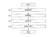
- FIG. 2 is a flowchart showing a flow of a series of image processing according to the embodiment
- FIG. 3 is a flowchart showing a flow of processing in an area dividing unit.
- FIG. 4 is a schematic diagram of an image after region division.
- an input image that is a radiographic image obtained by a radiographic imaging device will be described as an example of an image processing target.
- the radiographic imaging apparatus includes a top plate 1 on which a subject M is placed, and a radiation source 2 (eg, X-rays) that radiates radiation (eg, X-rays) toward the subject M.
- a radiation source 2 eg, X-rays
- X-ray tube e.g. X-ray tube
- FPD flat panel radiation detector
- An image processing unit 4 that performs image processing
- a display unit 5 that displays radiographic images subjected to various types of image processing by the image processing unit 4.
- the display unit 5 includes display means such as a monitor and a television.
- the image processing unit 4 is incorporated in the radiographic image capturing apparatus.
- the image processing unit 4 corresponds to the image processing device in this invention.
- the radiation detector may be a radiation detector other than a flat panel radiation detector (FPD).
- FPD flat panel radiation detector
- I.I image intensifier
- the analog image may be sent to the image processing unit 4 and converted into a digital image. In this embodiment, this digital image is used as an input image.
- numerical values are expressed in decimal numbers, but it should be noted that they are actually processed in binary numbers.
- the image processing unit 4 includes a central processing unit (CPU).
- CPU central processing unit
- a program for performing various image processing is written and stored in a storage medium represented by ROM (Read-only Memory) and the like, and the CPU of the image processing unit 4 executes the program from the storage medium.
- ROM Read-only Memory
- an index value calculation unit 41, a pixel detection unit 42, a region division unit 43, and a process switching unit 44, which will be described later, of the image processing unit 4 have programs relating to calculation of index values, detection of detected pixels, region division, and processing switching.
- index value calculation, detection pixel detection, area division, and process switching are performed according to the program (see the flowchart in FIG. 2).
- a program related to calculation of index values, detection of detected pixels, area division, and processing switching corresponds to the image processing program according to the present invention.
- the radiation image obtained by detection with the FPD 3 is sent to the image processing unit 4 as an input image.
- the image processing unit 4 includes an index value calculation unit 41 that calculates an index value indicating the degree of dispersion of the luminance value from the luminance distribution in the vicinity of the pixel in each pixel of the input image, and an index value in each pixel.
- An input image based on a pixel detection unit 42 that detects, as a detection pixel, a pixel that has a relative peak value in a neighboring region and whose index value exceeds a predetermined range;
- An area dividing unit 43 that classifies the pixels therein and divides the area into a plurality of areas, and a process switching unit 44 that performs different processing by changing the filter characteristics or the filter strength for each divided area.
- the index value calculation unit 41 corresponds to the index value calculation unit in the present invention
- the pixel detection unit 42 corresponds to the pixel detection unit in the present invention
- the region division unit 43 corresponds to the region division unit in the present invention.
- the process switching unit 44 corresponds to the process switching means in this invention.
- the FPD 3 is connected to the index value calculation unit 41 and the process switching unit 44, and a radiation image (input image) is sent to each.
- the index value calculation unit 41 is connected to the pixel detection unit 42, and the index value is sent to the pixel detection unit 42.
- the pixel detection unit 42 is connected to the region dividing unit 43, and the detection pixel is sent to the region dividing unit 43.
- the area dividing unit 43 is connected to the process switching unit 44, and the divided areas are sent to the process switching unit 44.
- the image after the enhancement processing by the process switching unit 44 is sent to the display unit 5 and displayed.
- steps S1 to S4 in FIG. 2 may be performed using pixel values before gradation conversion, or steps S1 to S4 in FIG. 2 may be performed using luminance values after gradation conversion.
- Step S1 Index Value Calculation
- the index value calculation unit 41 calculates an index value indicating the degree of dispersion of the luminance value from the luminance distribution in the vicinity of the pixel in each pixel of the input image.
- pixel value data included in a rectangular range for example, an image of 9 ⁇ 9 pixels
- a standard deviation is calculated as an index value. The above calculation is similarly calculated for all pixels in the image.
- the next pixel for example, an adjacent pixel
- the newly set range in the vicinity of the pixel centered on the target pixel in this case, a rectangular range
- the previous pixel neighboring range in this case, a rectangular range
- scanning may be performed so that the newly set pixel vicinity range (rectangular range) and the previous pixel vicinity range (rectangular range) do not overlap.
- the pixel value is folded and pasted. In this way, the pixel range may be generated virtually.
- the size of the range in the vicinity of the pixel (rectangular range) may be changed as described later.
- the size of the range in the vicinity of the pixel may be changed according to the image size or the subject size.
- the range in the vicinity of the pixel is not limited to the rectangular range described above, and may be another shape such as a region (for example, a circular region) within a certain distance around the target pixel. Although described as circular here, it should be noted that since the pixel is a square dot, it is actually a polygon that is as close to a circle as possible.
- the index value indicating the degree of dispersion of luminance values is not limited to the standard deviation described above, and may be an index that statistically indicates the degree of dispersion of luminance values, such as a deviation from a dispersion value or an average value. Other numbers are also acceptable.
- This step S1 corresponds to an index value calculating step in the present invention.
- Step S2 Pixel Detection
- the pixel detection unit 42 detects, as a detection pixel, a pixel that has a relative peak value in the vicinity region and has an index value exceeding a predetermined range in the index value of each pixel.
- index value data included in a rectangular range for example, an image of 9 ⁇ 9 pixels
- the index value calculation unit 41 is acquired from the index value calculation unit 41, and the following (1
- a pixel having a significantly large value in the vicinity region is detected as a detection pixel as compared with the average value of the index value data (see the first term on the left side of equation (1)).
- the index value at the target pixel P (x, y) is I (x, y) and the neighboring region R xy
- a pixel satisfying the following expression (1) is detected as a detection pixel.
- ⁇ is a constant of about 1.0 to 1.2.
- the specific value of ⁇ is not particularly limited.
- An identification number or identifier (symbol or character) for identifying a region is set for the detected pixel detected.
- the method for detecting pixels is not limited to this.
- the standard deviation or variance value of the index value may be calculated, and pixels outside the set distribution (deviation value, etc.) range may be detected.
- This step S2 corresponds to the pixel detection step in the present invention.
- Step S3 Region Division
- the region division unit 43 classifies the pixels in the input image based on the pixel region formed of the detection pixels and divides the region into a plurality of regions.
- the pixel detection unit 42 is divided into three areas including a set of detected pixels, a set of pixels near the detected pixel, and a set of other pixels. For each pixel, an identification number or an identifier (symbol or character) for identifying the region is set.
- Step T1 Detection pixel? It is determined whether the target pixel (that is, the target pixel) is a detection pixel detected by the pixel detection unit 42. If it is not a detection pixel, the process proceeds to step T2. If it is a detection pixel, the process proceeds to step T6.
- Step T2 Proximity? It is determined whether or not the pixel of interest is a pixel close to (for example, adjacent to) the detection pixel. If the pixel is not adjacent to the detection pixel, the process proceeds to step T3. If the pixel is close to the detection pixel, the process proceeds to step T7. In step T2, the region setting is not limited to adjacent pixels. For example, it may be determined whether or not the detection pixel is within a certain range.
- Step T3 Region 3 Identifier Setting If the pixel is not close to the detected pixel, the “region 3” identifier is set, and the process proceeds to step T4.
- Step T4 All pixels? It is checked whether or not the determination is made for all the pixels. If the determination is not made for all the pixels, the process proceeds to Step T5. If the determination is made for all the pixels, steps T1 to T7 are ended.
- Step T5 Next Pixel If all the pixels have not been determined, the next pixel (for example, an adjacent pixel) is set as the target pixel to move to the next pixel, and the process returns to Step T1. Similar determinations and settings are made.
- Step T6 Region 1 Identifier Setting If it is a detected pixel, the identifier of “region 1” is set, and the process proceeds to step T4.
- Step T7 Region 2 Identifier Setting If the pixel is close to the detected pixel, the “region 2” identifier is set, and the process proceeds to step T4.
- the pixels in the input image are classified and divided into a plurality of (here, three) regions.
- An example of an image after region division is shown in FIG.
- Reference numeral 1 in FIG. 4 represents a detection pixel area (identifier of area 1)
- reference numeral 2 in FIG. 4 represents an area in the vicinity of the detection pixel (identifier of area 2)
- reference numeral 3 in FIG. Represents an area (identifier of area 3).
- Step S3 (see FIG. 2) including steps T1 to T7 (see FIG. 3) corresponds to the region dividing step in the present invention.
- Step S4 Process Switching
- the process switching unit 44 changes the filter characteristics or the filter strength for each divided region, and performs different processes.
- a filter generally used for image enhancement processing is used.
- the following unsharp masking filter see the following equation (2) is used.
- s is a filter size and k is a constant.
- the area of the detected pixel detected by the pixel detection unit 42 (identifier of area 1 in FIG. 4), the area in the vicinity of the detected pixel (identifier of area 2 in FIG. 4), and other areas (identifier of area 3 in FIG. 4)
- the filter size is fixed and the value of k is set to a value such as 2, 1, 0.5.
- other values may be set as long as the emphasis levels are in order.
- the value of the constant k may be fixed and the filter size may be changed for each divided area. In this case, a large value of the filter size is set in an area where the enhancement level is strong. Further, both the filter size and the constant may be changed. The same process is performed when the number of area divisions is 4 or more.
- an average value of a processing result with a strong emphasis level and a processing result with a weak emphasis level may be output.
- the enhancement processing is not limited to this, and any other known method may be used as long as it is a filter processing for enhancing the contrast or edge of the image.
- This step S4 corresponds to a process switching step in the present invention.
- the display unit 5 receives the processed image (processing result data) from the processing switching unit 44, and outputs and displays it on a display device such as a monitor. Further, the output result is written and stored in a storage medium (not shown) such as a hard disk or memory represented by RAM (Random Access Memory).
- a storage medium such as a hard disk or memory represented by RAM (Random Access Memory).
- an index value I (x, y) indicating the degree of dispersion of the luminance value is calculated from the luminance distribution in the vicinity of the pixel.
- the image enhancement level filter characteristics or filter strength
- Enhancement processing can be performed with high accuracy from the luminance portion to the high luminance portion.
- there is no setting depending on the magnitude of the luminance value fine setting and adjustment before shooting are unnecessary, and even when the shooting environment and shooting conditions change, highly accurate processing can be performed stably.
- pixel detection and area division are performed based on the relative peak value in the vicinity area, there is no erroneous detection or malfunction due to noise or the like.
- the filter strength is set to be weaker as the distance between the detection pixel and the target pixel becomes longer, and the target pixel is processed with the set filter. Is preferred. If the detection pixel is a target pixel, the filter strength is set to the strongest (in the case of an unsharp mask filter, for example, the value of k is set to 2), and the target pixel (that is, the detection pixel) is set. Is processed with the set filter. Then, as the distance between the detection pixel and the target pixel becomes longer, the filter strength is decreased (in the case of an unsharp mask filter, for example, the value of k is set to a value of 1,0.5), A process using the set filter is performed on the target pixel.
- an unsharp mask filter for example, the value of k is set to 2
- a strongly set filter In a pixel having a relatively large index value indicating the degree of dispersion in the vicinity region (that is, a detection pixel), processing with a strongly set filter can be performed. It is considered that the index value of the target pixel becomes relatively smaller as the distance from the detection pixel becomes longer in the vicinity region. Therefore, in a pixel having a long distance from the detection pixel and a relatively small index value, processing with a weakly set filter can be performed.
- the region dividing unit 43 preferably divides the region into a plurality of regions (three in FIG. 4) according to the distance from the detection pixel, as shown in FIG.
- the index value of the target pixel becomes relatively smaller as the distance from the detection pixel becomes longer in the vicinity region. Therefore, by dividing the area into multiple areas according to the distance from the detection pixel, changing the filter characteristics or filter strength for each divided area, and performing different processing for each area, the enhancement process is highly accurate. Can be done. If the area is divided into a plurality of areas, the number of area divisions is not particularly limited.
- the computer by causing the computer to execute the processes in steps S1 to S4 in FIG. 2 corresponding to the index value calculating process, the pixel detecting process, the area dividing process, and the process switching process.
- the contrast of the region to be emphasized can be optimally emphasized.
- the present invention is not limited to the above embodiment, and can be modified as follows.
- an input image which is a radiographic image obtained by a radiographic imaging device
- the input image is not particularly limited, such as a digital image obtained by a digital image capturing apparatus or a digital image obtained by digitally converting an analog image as an input image.
- nuclear medicine data of a subject to which a radiopharmaceutical is administered obtained by a nuclear medicine diagnostic apparatus may be used as an input image.
- the present invention is applied to a medical radiographic imaging apparatus in which the subject is a human body.
- the subject may be applied to a nondestructive inspection apparatus that images the internal structure of a substrate other than the human body. .
- the image processing unit (image processing device) is incorporated in the radiation image capturing device, but the radiation image capturing device may be an external device and the image processing unit (image processing device) may be a single unit.
- the present invention is suitable for a radiographic image capturing device, and a digital image capturing device such as a digital camera or a digital video.
Landscapes
- Physics & Mathematics (AREA)
- General Physics & Mathematics (AREA)
- Engineering & Computer Science (AREA)
- Theoretical Computer Science (AREA)
- Image Processing (AREA)
- Apparatus For Radiation Diagnosis (AREA)
Abstract
Description
すなわち、この発明の画像処理装置は、入力画像を処理する画像処理装置であって、当該入力画像のそれぞれの画素において、画素近傍の輝度分布から、輝度値の散らばり度合いを示す指標値を算出する指標値算出手段と、前記それぞれの画素における指標値において、近傍領域内で相対的にピーク値を有し、かつ指標値が所定の範囲を超える画素を検出画素として検出する画素検出手段と、前記検出画素で構成される画素領域に基づいて、前記入力画像中の画素を分類して複数の領域に領域分割する領域分割手段と、分割された分割領域毎にフィルタの特性またはフィルタの強度を変更して、それぞれ異なる処理を行う処理切り替え手段とを備えることを特徴とするものである。
また、この発明の画像処理プログラムによれば、指標値算出工程,画素検出工程,領域分割工程および処理切り替え工程での処理をコンピュータに実行させることにより、撮影環境や撮影条件が変化した場合でも、精度の高い処理を安定して行うことができる。
指標値算出部41は、入力画像のそれぞれの画素において、画素近傍の輝度分布から、輝度値の散らばり度合いを示す指標値を算出する。本実施例では、注目画素を中心とする所定の大きさの矩形範囲(例えば9×9画素の画像)に含まれる画素値データをFPD3から取得し、指標値として標準偏差を算出する。上記の演算を、画像中の全ての画素に関して、同様に算出する。このように、指標値を算出した後に次の画素(例えば隣接する画素)を注目画素として新たに設定し、新たに設定された当該注目画素を中心とする画素近傍の範囲(ここでは矩形範囲)と前回の画素近傍の範囲(矩形範囲)とが重複するように走査する。
画素検出部42は、それぞれの画素における指標値において、近傍領域内で相対的にピーク値を有し、かつ指標値が所定の範囲を超える画素を検出画素として検出する。本実施例では、上述したように注目画素を中心とする所定の大きさの矩形範囲(例えば9×9画素の画像)に含まれる指標値データを指標値算出部41から取得し、下記(1)式のように指標値データの平均値((1)式の左辺の第1項を参照)と比較して、近傍領域内で大幅に大きな値を示す画素を検出画素として検出する。具体的には、注目画素P(x,y)における指標値をI(x,y)とし、近傍領域Rxyとすると、下記(1)式を満たす画素を検出画素として検出する。

領域分割部43は、検出画素で構成される画素領域に基づいて、入力画像中の画素を分類して複数の領域に領域分割する。本実施例では、画素検出部42で検出された検出画素の集合,検出画素近傍の画素の集合,その他の画素の集合からなる3つの領域に分割する。それぞれの画素には、領域を識別する識別番号または識別子(記号や文字)を設定する。
対象となる画素(すなわち注目画素)において、画素検出部42で検出された検出画素であるか否かを判定する。検出画素でない場合にはステップT2に進む。検出画素である場合にはステップT6に進む。
注目画素において、検出画素に近接(例えば隣接)する画素であるか否かを判定する。検出画素に近接する画素でない場合にはステップT3に進む。検出画素に近接する画素である場合にはステップT7に進む。このステップT2では、領域の設定は、近接する画素に限定されることはない。例えば、検出画素から一定の範囲内であるか否かなどの判定を行っても構わない。
検出画素に近接する画素でない場合には「領域3」の識別子を設定し、ステップT4に進む。
全ての画素に関して判定が行われたか否かを調べ、全ての画素に関して判定が行われていない場合にはステップT5に進む。全ての画素に関して判定が行われた場合にはステップT1~T7を終了する。
全ての画素に関して判定が行われていない場合には次の画素(例えば隣接する画素)を注目画素として設定することで当該次の画素に移動し、ステップT1に戻って同様の判定や設定を行う。
検出画素である場合には「領域1」の識別子を設定し、ステップT4に進む。
検出画素に近接する画素である場合には「領域2」の識別子を設定し、ステップT4に進む。
処理切り替え部44は、分割された分割領域毎にフィルタの特性またはフィルタの強度を変更して、それぞれ異なる処理を行う。フィルタには、一般的に画像の強調処理に使用されるものを用いる。本実施例では、例えば、以下に示すアンシャープマスクフィルタ(unsharp masking filter)(下記(2)式を参照)を利用する。

41 … 指標値算出部
42 … 画素検出部
43 … 領域分割部
44 … 処理切り替え部
I(x,y) … 指標値
Claims (4)
- 入力画像を処理する画像処理装置であって、
当該入力画像のそれぞれの画素において、画素近傍の輝度分布から、輝度値の散らばり度合いを示す指標値を算出する指標値算出手段と、
前記それぞれの画素における指標値において、近傍領域内で相対的にピーク値を有し、かつ指標値が所定の範囲を超える画素を検出画素として検出する画素検出手段と、
前記検出画素で構成される画素領域に基づいて、前記入力画像中の画素を分類して複数の領域に領域分割する領域分割手段と、
分割された分割領域毎にフィルタの特性またはフィルタの強度を変更して、それぞれ異なる処理を行う処理切り替え手段と
を備えることを特徴とする画像処理装置。 - 請求項1に記載の画像処理装置において、
前記検出画素と対象となる画素との距離が長くなるのにしたがって前記フィルタの強度を弱く設定して、前記処理切り替え手段は、当該対象となる画素に対して当該設定されたフィルタでの処理を行うことを特徴とする画像処理装置。 - 請求項1または請求項2に記載の画像処理装置において、
前記領域分割手段は、前記検出画素からの距離にしたがって複数の領域に領域分割することを特徴とする画像処理装置。 - 入力画像を処理する画像処理をコンピュータに実行させるための画像処理プログラムであって、
当該入力画像のそれぞれの画素において、画素近傍の輝度分布から、輝度値の散らばり度合いを示す指標値を算出する指標値算出工程と、
前記それぞれの画素における指標値において、近傍領域内で相対的にピーク値を有し、かつ指標値が所定の範囲を超える画素を検出画素として検出する画素検出工程と、
前記検出画素で構成される画素領域に基づいて、前記入力画像中の画素を分類して複数の領域に領域分割する領域分割工程と、
分割された分割領域毎にフィルタの特性またはフィルタの強度を変更して、それぞれ異なる処理を行う処理切り替え工程と
を備え、
これらの工程での処理をコンピュータに実行させることを特徴とする画像処理プログラム。
Priority Applications (5)
| Application Number | Priority Date | Filing Date | Title |
|---|---|---|---|
| US15/574,763 US10402951B2 (en) | 2015-05-22 | 2015-05-22 | Image processing device and image processing program |
| PCT/JP2015/064823 WO2016189601A1 (ja) | 2015-05-22 | 2015-05-22 | 画像処理装置および画像処理プログラム |
| CN201580080273.4A CN107613870B (zh) | 2015-05-22 | 2015-05-22 | 图像处理装置以及图像处理程序 |
| JP2017520079A JP6566029B2 (ja) | 2015-05-22 | 2015-05-22 | 画像処理装置および画像処理プログラム |
| TW105115266A TWI590807B (zh) | 2015-05-22 | 2016-05-18 | Image processing device and image processing program |
Applications Claiming Priority (1)
| Application Number | Priority Date | Filing Date | Title |
|---|---|---|---|
| PCT/JP2015/064823 WO2016189601A1 (ja) | 2015-05-22 | 2015-05-22 | 画像処理装置および画像処理プログラム |
Publications (1)
| Publication Number | Publication Date |
|---|---|
| WO2016189601A1 true WO2016189601A1 (ja) | 2016-12-01 |
Family
ID=57392991
Family Applications (1)
| Application Number | Title | Priority Date | Filing Date |
|---|---|---|---|
| PCT/JP2015/064823 Ceased WO2016189601A1 (ja) | 2015-05-22 | 2015-05-22 | 画像処理装置および画像処理プログラム |
Country Status (5)
| Country | Link |
|---|---|
| US (1) | US10402951B2 (ja) |
| JP (1) | JP6566029B2 (ja) |
| CN (1) | CN107613870B (ja) |
| TW (1) | TWI590807B (ja) |
| WO (1) | WO2016189601A1 (ja) |
Citations (2)
| Publication number | Priority date | Publication date | Assignee | Title |
|---|---|---|---|---|
| JP2005323926A (ja) * | 2004-05-17 | 2005-11-24 | Ge Medical Systems Global Technology Co Llc | 画像処理方法、画像処理装置およびx線ct装置 |
| JP2009050356A (ja) * | 2007-08-24 | 2009-03-12 | Hitachi Medical Corp | 医用画像の特定領域抽出方法 |
Family Cites Families (7)
| Publication number | Priority date | Publication date | Assignee | Title |
|---|---|---|---|---|
| JPS5579639A (en) | 1978-12-08 | 1980-06-16 | Hitachi Ltd | Interpolar connecting device of revolving-field coil |
| JP3778229B2 (ja) * | 1996-05-13 | 2006-05-24 | 富士ゼロックス株式会社 | 画像処理装置、画像処理方法、および画像処理システム |
| JP5804340B2 (ja) * | 2010-06-10 | 2015-11-04 | 株式会社島津製作所 | 放射線画像領域抽出装置、放射線画像領域抽出プログラム、放射線撮影装置および放射線画像領域抽出方法 |
| US20130100310A1 (en) * | 2010-07-05 | 2013-04-25 | Nikon Corporation | Image processing device, imaging device, and image processing program |
| JP5579639B2 (ja) | 2011-02-26 | 2014-08-27 | ジーイー・メディカル・システムズ・グローバル・テクノロジー・カンパニー・エルエルシー | 画像処理装置およびプログラム並びに画像診断装置 |
| KR102445242B1 (ko) * | 2014-03-19 | 2022-09-21 | 삼성전자주식회사 | 경계 필터링을 수반한 비디오 부호화 및 비디오 복호화 방법 및 장치 |
| US10262397B2 (en) * | 2014-12-19 | 2019-04-16 | Intel Corporation | Image de-noising using an equalized gradient space |
-
2015
- 2015-05-22 WO PCT/JP2015/064823 patent/WO2016189601A1/ja not_active Ceased
- 2015-05-22 JP JP2017520079A patent/JP6566029B2/ja active Active
- 2015-05-22 CN CN201580080273.4A patent/CN107613870B/zh active Active
- 2015-05-22 US US15/574,763 patent/US10402951B2/en active Active
-
2016
- 2016-05-18 TW TW105115266A patent/TWI590807B/zh not_active IP Right Cessation
Patent Citations (2)
| Publication number | Priority date | Publication date | Assignee | Title |
|---|---|---|---|---|
| JP2005323926A (ja) * | 2004-05-17 | 2005-11-24 | Ge Medical Systems Global Technology Co Llc | 画像処理方法、画像処理装置およびx線ct装置 |
| JP2009050356A (ja) * | 2007-08-24 | 2009-03-12 | Hitachi Medical Corp | 医用画像の特定領域抽出方法 |
Also Published As
| Publication number | Publication date |
|---|---|
| TWI590807B (zh) | 2017-07-11 |
| JP6566029B2 (ja) | 2019-08-28 |
| US20180204312A1 (en) | 2018-07-19 |
| CN107613870B (zh) | 2021-03-26 |
| US10402951B2 (en) | 2019-09-03 |
| TW201705912A (zh) | 2017-02-16 |
| CN107613870A (zh) | 2018-01-19 |
| JPWO2016189601A1 (ja) | 2017-12-28 |
Similar Documents
| Publication | Publication Date | Title |
|---|---|---|
| US9437017B2 (en) | Method and apparatus for metal artifact elimination in a medical image | |
| JP6567094B2 (ja) | 放射線映像の処理方法及び放射線撮影システム | |
| US10660598B2 (en) | Image processing apparatus, image processing method, and image processing system | |
| JP5416377B2 (ja) | 画像処理装置及びそれを備えたx線異物検出装置並びに画像処理方法 | |
| US11127123B2 (en) | Medical image processing device and medical image processing method | |
| US9619893B2 (en) | Body motion detection device and method | |
| WO2015133123A1 (ja) | 放射線画像処理装置および方法並びにプログラム | |
| US9595116B2 (en) | Body motion detection device and method | |
| JP2016087222A (ja) | 画像処理装置及びプログラム | |
| CN106255462A (zh) | 图像诊断装置及灰度信息设定方法 | |
| JP7075773B2 (ja) | 画像処理装置、顕微鏡システム、画像処理方法および画像処理プログラム | |
| CN104933681B (zh) | 图像处理装置以及图像处理方法 | |
| KR20130128690A (ko) | 영상 처리 방법 및 그에 따른 영상 처리 장치 | |
| JP6105903B2 (ja) | 画像処理装置、画像処理方法、放射線撮影システム及びプログラム | |
| JP6566029B2 (ja) | 画像処理装置および画像処理プログラム | |
| JP2001148787A (ja) | 画像処理装置 | |
| JP7502868B2 (ja) | 画像処理装置および方法、プログラム | |
| Takei et al. | A new automated assessment method for contrast–detail images by applying support vector machine and its robustness to nonlinear image processing | |
| JP2002159477A (ja) | 異常陰影候補の検出方法 | |
| JP2024028043A (ja) | 情報処理装置、情報処理方法、及びプログラム |
Legal Events
| Date | Code | Title | Description |
|---|---|---|---|
| 121 | Ep: the epo has been informed by wipo that ep was designated in this application |
Ref document number: 15893237 Country of ref document: EP Kind code of ref document: A1 |
|
| ENP | Entry into the national phase |
Ref document number: 2017520079 Country of ref document: JP Kind code of ref document: A |
|
| WWE | Wipo information: entry into national phase |
Ref document number: 15574763 Country of ref document: US |
|
| NENP | Non-entry into the national phase |
Ref country code: DE |
|
| 122 | Ep: pct application non-entry in european phase |
Ref document number: 15893237 Country of ref document: EP Kind code of ref document: A1 |