WO2016187852A1 - Procédé et dispositif de commutation d'équipement d'utilisateur - Google Patents
Procédé et dispositif de commutation d'équipement d'utilisateur Download PDFInfo
- Publication number
- WO2016187852A1 WO2016187852A1 PCT/CN2015/079986 CN2015079986W WO2016187852A1 WO 2016187852 A1 WO2016187852 A1 WO 2016187852A1 CN 2015079986 W CN2015079986 W CN 2015079986W WO 2016187852 A1 WO2016187852 A1 WO 2016187852A1
- Authority
- WO
- WIPO (PCT)
- Prior art keywords
- network device
- user equipment
- information
- destination network
- uplink resource
- Prior art date
Links
- 238000000034 method Methods 0.000 title claims abstract description 115
- 230000005540 biological transmission Effects 0.000 claims description 13
- 238000011144 upstream manufacturing Methods 0.000 claims description 8
- 230000008569 process Effects 0.000 abstract description 19
- 238000004891 communication Methods 0.000 abstract description 9
- 238000010586 diagram Methods 0.000 description 17
- 230000011664 signaling Effects 0.000 description 16
- 238000005259 measurement Methods 0.000 description 15
- 230000006870 function Effects 0.000 description 5
- 230000001960 triggered effect Effects 0.000 description 4
- 230000008878 coupling Effects 0.000 description 3
- 238000010168 coupling process Methods 0.000 description 3
- 238000005859 coupling reaction Methods 0.000 description 3
- 230000003993 interaction Effects 0.000 description 3
- 238000010295 mobile communication Methods 0.000 description 3
- 230000001413 cellular effect Effects 0.000 description 1
- 238000006243 chemical reaction Methods 0.000 description 1
- 239000003795 chemical substances by application Substances 0.000 description 1
- 238000005516 engineering process Methods 0.000 description 1
- 230000000977 initiatory effect Effects 0.000 description 1
- 230000007774 longterm Effects 0.000 description 1
- 230000003287 optical effect Effects 0.000 description 1
- 230000004044 response Effects 0.000 description 1
Images


Classifications
-
- H—ELECTRICITY
- H04—ELECTRIC COMMUNICATION TECHNIQUE
- H04W—WIRELESS COMMUNICATION NETWORKS
- H04W36/00—Hand-off or reselection arrangements
- H04W36/08—Reselecting an access point
-
- H—ELECTRICITY
- H04—ELECTRIC COMMUNICATION TECHNIQUE
- H04L—TRANSMISSION OF DIGITAL INFORMATION, e.g. TELEGRAPHIC COMMUNICATION
- H04L65/00—Network arrangements, protocols or services for supporting real-time applications in data packet communication
- H04L65/40—Support for services or applications
-
- H—ELECTRICITY
- H04—ELECTRIC COMMUNICATION TECHNIQUE
- H04W—WIRELESS COMMUNICATION NETWORKS
- H04W36/00—Hand-off or reselection arrangements
- H04W36/0005—Control or signalling for completing the hand-off
-
- H—ELECTRICITY
- H04—ELECTRIC COMMUNICATION TECHNIQUE
- H04W—WIRELESS COMMUNICATION NETWORKS
- H04W36/00—Hand-off or reselection arrangements
- H04W36/0005—Control or signalling for completing the hand-off
- H04W36/0055—Transmission or use of information for re-establishing the radio link
- H04W36/0072—Transmission or use of information for re-establishing the radio link of resource information of target access point
-
- H—ELECTRICITY
- H04—ELECTRIC COMMUNICATION TECHNIQUE
- H04W—WIRELESS COMMUNICATION NETWORKS
- H04W36/00—Hand-off or reselection arrangements
- H04W36/34—Reselection control
- H04W36/38—Reselection control by fixed network equipment
-
- H—ELECTRICITY
- H04—ELECTRIC COMMUNICATION TECHNIQUE
- H04W—WIRELESS COMMUNICATION NETWORKS
- H04W56/00—Synchronisation arrangements
- H04W56/001—Synchronization between nodes
-
- H—ELECTRICITY
- H04—ELECTRIC COMMUNICATION TECHNIQUE
- H04W—WIRELESS COMMUNICATION NETWORKS
- H04W72/00—Local resource management
- H04W72/20—Control channels or signalling for resource management
-
- H—ELECTRICITY
- H04—ELECTRIC COMMUNICATION TECHNIQUE
- H04W—WIRELESS COMMUNICATION NETWORKS
- H04W36/00—Hand-off or reselection arrangements
- H04W36/02—Buffering or recovering information during reselection ; Modification of the traffic flow during hand-off
Definitions
- the present invention relates to the field of communications technologies, and in particular, to a user equipment switching method and device.
- the UE notifies the control node, which node is the target node to which the UE is to be handed over. After receiving the notification, the control node notifies the target node to prepare access resources for the UE, and notifies the UE to access the target node. Then, the UE starts a random access procedure at the target node to obtain an uplink resource, and after obtaining the uplink resource, the UE may perform uplink data transmission by using the obtained uplink resource.
- the embodiment of the invention provides a user equipment switching method and device, which are used to solve the technical problem that the user equipment has low switching efficiency when performing handover.
- the first aspect provides a user equipment switching method, including:
- the user equipment sends the first information to the control network device or the source network device, where the first information is used to request the user equipment to switch from the source network device to the destination network device;
- the user equipment receives the second information from the destination network device, the source network device, or the control network device, where the second information is used to notify the destination network device of the first uplink allocated by the user equipment Resources.
- the method further includes:
- the user equipment receives the synchronization signal that is temporarily sent by the destination network device, and the synchronization signal is used by the user equipment to complete downlink synchronization with the destination network device.
- the method before the user equipment receives the synchronization signal that the destination network device temporarily increases the transmission, the method further include:
- the receiving, by the user equipment, the synchronization signal that is temporarily sent by the destination network device includes:
- the user equipment is connected to the control network device or the source network device After the first information is sent, the method further includes:
- the user equipment receives the device identifier from the destination network device or the control network device, where the device identifier is: a unique identifier of the user equipment within the coverage of the destination network device.
- An uplink resource is a PUSCH resource or a PUCCH resource.
- the method further includes:
- the user equipment sends a buffer status report or a data packet to the destination network device by using the first uplink resource;
- the user equipment sends scheduling request information to the destination network device by using the first uplink resource.
- the user equipment receives, by the user equipment, the source network device, the source network device, or the control network device After the second information, the method further includes:
- the user equipment sends the downlink TEID and the IP address of the destination network device to the control network device.
- the second aspect provides a user equipment switching method, including:
- the destination network device receives the third information from the control network device or the source network device, where the third information is used to indicate that the user equipment requests to switch to the destination network device;
- the destination network device allocates a first uplink resource to the user equipment.
- the method further includes:
- the destination network device temporarily adds a transmission synchronization signal to the user equipment, where the synchronization signal is used to complete downlink synchronization between the user equipment and the destination network device.
- the method also includes:
- the destination network device sends the second information to the user equipment, where the second information is used to notify the destination network device of the first uplink resource allocated by the user equipment;
- the destination network device sends fourth information to the control network device, where the fourth information is used to notify the destination network device of the first uplink resource allocated by the user equipment.
- the target network device is the user equipment After the first uplink resource is allocated, the method further includes:
- the destination network device sends the device identifier that is allocated to the user equipment to the user equipment, where the device identifier is: a unique identifier of the user equipment within the coverage of the destination network device; or
- the device identifier is: a unique identifier of the user equipment within the coverage of the destination network device.
- An uplink resource is a PUSCH resource or a PUCCH resource.
- the method further includes :
- the destination network device receives the scheduling request information sent by the user equipment by using the first uplink resource
- the destination network device receives, by using the first uplink resource, a cache status report or a data packet sent by the user equipment.
- a third aspect provides a user equipment switching method, including:
- the control network device receives the first information from the user equipment, where the first information is used to indicate that the user equipment requests to switch from the source network device to the destination network device;
- the control network device sends the third information to the destination network device, and requests the destination network device to allocate a first uplink resource to the user equipment; the third information is used to indicate that the user equipment requests to switch to The destination network device.
- the method further includes:
- the control network device receives the fourth information from the destination network device, where the fourth information is used to notify the destination network device of the first uplink resource allocated by the user equipment;
- the control network device sends the second information to the user equipment according to the fourth information, where the second information is used to notify the destination network device of the first uplink resource allocated by the user equipment.
- the second in the third aspect after the control network device requests the destination network device to allocate the first uplink resource to the user equipment, the method further includes:
- the control network device notifies the user equipment of the symbol position of the synchronization signal; wherein the synchronization signal is temporarily added to the user equipment for the destination network device, and is used for the user equipment and the destination network
- the device completes the signal for downlink synchronization.
- the control network device requests the destination network After the device allocates the first uplink resource to the user equipment, the method further includes:
- the control network device receives the device identifier from the destination network device, where the device identifier is: a unique identifier of the user equipment within the coverage of the destination network device;
- the control network device sends the device identifier to the user device.
- a fourth aspect provides a user equipment switching method, including:
- the source network device to which the user equipment belongs receives the first information from the user equipment, where the first information is used to indicate that the user equipment requests to switch from the source network device to the destination network device;
- the source network device sends the third information to the destination network device, and requests the destination network device to allocate the first uplink resource to the user equipment; the third information is used to indicate that the user equipment requests the The source network device switches to the destination network device.
- the method further includes:
- a user equipment including:
- a sending module configured to send, to the control network device or the source network device, the first information, where the first information is used to request the user equipment to switch from the source network device to the destination network device;
- a receiving module configured to receive from the destination network device, the source network device, or the control network
- the network device receives the second information, where the second information is used to notify the destination network device of the first uplink resource allocated by the user equipment.
- the receiving module is further configured to:
- the transmitting module After the transmitting module sends the first information to the control network device or the source network device, the receiving the synchronization signal is temporarily added by the destination network device, where the synchronization signal is used by the user equipment and the destination network device to complete the downlink. Synchronize.
- the receiving module is further configured to:
- the receiving module is further specifically configured to:
- the destination network device Receiving, according to the received symbol position, the destination network device temporarily increases the transmitted synchronization signal.
- the receiving module is further configured to:
- the sending module sends the first information to the control network device or the source network device, receiving the device identifier from the destination network device or the control network device, where the device identifier is: within the coverage of the destination network device The unique identifier of the user equipment.
- An uplink resource is a PUSCH resource or a PUCCH resource.
- the sending module is further configured to:
- the receiving module After the receiving module receives the second information from the destination network device, the source network device, or the control network device, if the first uplink resource is the PUSCH resource, the first uplink resource is used.
- the destination network device sends a cache status report or a data packet; or,
- the receiving module After the receiving module receives the second information from the destination network device, the source network device, or the control network device, if the first uplink resource is the PUCCH resource, the first uplink resource is used.
- the destination network device sends scheduling request information.
- the sending module is also used to:
- the receiving module After receiving the second information from the destination network device, the source network device, or the control network device, the receiving module sends the downlink TEID and the IP address of the destination network device to the control network device.
- a network device including:
- a receiving module configured to receive third information from the control network device or the source network device, where the third information is used to indicate that the user equipment requests to switch to the network device;
- An allocating module configured to allocate a first uplink resource to the user equipment.
- the network device further includes: a sending module, configured to:
- the allocating module allocates the first uplink resource to the user equipment, temporarily adding a sending synchronization signal to the user equipment, where the synchronization signal is used to complete downlink synchronization between the user equipment and the network device.
- the network device further includes: a sending module, configured to:
- the allocating module allocates the first uplink resource to the user equipment, sending, to the user equipment, second information, where the second information is used to notify the network device to allocate the first Uplink resources;
- the allocating module allocates the first uplink resource to the user equipment, sending, to the control network device, fourth information, where the fourth information is used to notify the network device to allocate the first part to the user equipment An uplink resource.
- the network device further includes: a sending module, configured to:
- the device identifier that is allocated to the user equipment is sent to the user equipment, where the device identifier is: within the coverage of the network device, a unique identifier of the user equipment; or
- the device identifier that is allocated to the user equipment is sent to the control network device, where the device identifier is: within the coverage of the network device, A unique identifier of the user equipment.
- An uplink resource is a PUSCH resource or a PUCCH resource.
- the receiving module is further configured to:
- the allocating module allocates the first uplink resource to the user equipment, if the first uplink resource is the PUCCH resource, the scheduling request information sent by the user equipment is received by using the first uplink resource; or
- the allocation module allocates the first uplink resource to the user equipment, if the first uplink resource is the PUSCH resource, receiving, by using the first uplink resource, a cache status report or a data packet sent by the user equipment. .
- a network device including:
- a receiving module configured to receive first information from the user equipment, where the first information is used to indicate that the user equipment requests to switch from the source network device to the destination network device;
- a sending module configured to send the third information to the destination network device, and request the destination network device to allocate a first uplink resource to the user equipment, where the third information is used to indicate that the user equipment requests to switch to The destination network device.
- the receiving module is further configured to: request, by the sending module, the destination network device to use the After the first uplink resource is allocated, the user equipment receives the fourth information sent by the destination network device, where the fourth information is used to notify the destination network device of the first uplink resource allocated by the user equipment;
- the sending module is further configured to: send the second information to the user equipment according to the fourth information, where the second information is used to notify the destination network device of the first uplink resource allocated by the user equipment .
- the sending module is further configured to:
- the receiving module is further configured to: after the sending module requests the destination network device to allocate the first uplink resource to the user equipment, receive the device identifier sent by the destination network device, where the device identifier is: Describe the unique identifier of the user equipment within the coverage of the destination network device;
- the sending module is further configured to: send the device identifier to the user equipment.
- a network device including:
- a receiving module configured to receive first information from a user equipment, where the first information is used to indicate that the user equipment requests to switch from the network device to a destination network device;
- a sending module configured to send the third information to the destination network device, and request the destination network device to allocate a first uplink resource to the user equipment, where the third information is used to indicate that the user equipment is requested to be The network device switches to the destination network device.
- the sending module is further configured to:
- the receiving module After the receiving module receives the third information from the user equipment, uplinking the network device
- the TEID and the IP address are sent to the destination network device, and
- a user equipment including:
- a transmitter configured to send, to the control network device or the source network device, the first information, where the first information is used to request the user equipment to switch from the source network device to the destination network device;
- a receiver configured to receive second information from the destination network device, the source network device, or the control network device, where the second information is used to notify the destination network device to allocate the first information to the user equipment Upstream resources.
- the receiver is further configured to:
- the destination network device After the first information is sent by the sender to the control network device or the source network device, the destination network device receives the synchronization signal that is temporarily sent, and the synchronization signal is used by the user equipment to complete the downlink with the destination network device. Synchronize.
- the receiver is specifically configured to:
- the destination network device Receiving, according to the received symbol position, the destination network device temporarily increases the transmitted synchronization signal.
- the receiver is further configured to:
- the device identifier is received from the destination network device or the control network device, where the device identifier is: within the coverage of the destination network device The unique identifier of the user equipment.
- the first uplink resource is a PUSCH resource or a PUCCH resource.
- the transmitter is further configured to:
- the receiver After the receiver receives the second information from the destination network device, the source network device, or the control network device, if the first uplink resource is the PUSCH resource, the first uplink resource is used.
- the destination network device sends a cache status report or a data packet; or,
- the receiver After the receiver receives the second information from the destination network device, the source network device, or the control network device, if the first uplink resource is the PUCCH resource, the first uplink resource is used.
- the destination network device sends scheduling request information.
- the transmitter is also used to:
- the receiver After the receiver receives the second information from the destination network device, the source network device, or the control network device, sending the TEID and the IP address of the destination network device to the control network device.
- a network device including:
- a receiver configured to receive third information from the control network device or the source network device, where the third information is used to indicate that the user equipment requests to switch to the network device;
- the processor is configured to allocate a first uplink resource to the user equipment.
- the network device further includes: a transmitter, configured to:
- the network device further includes: a transmitter, configured to:
- the processor allocates the first uplink resource to the user equipment, to the user equipment Transmitting, by the second information, the first uplink resource allocated by the network device to the user equipment;
- the processor allocates the first uplink resource to the user equipment, sending, to the control network device, fourth information, where the fourth information is used to notify the network device to allocate the An uplink resource.
- the network device further includes a transmitter, where :
- the device identifier that is allocated to the user equipment is sent to the user equipment, where the device identifier is: within the coverage of the network device, a unique identifier of the user equipment; or
- the device identifier that is allocated to the user equipment is sent to the control network device, where the device identifier is: within the coverage of the network device, A unique identifier of the user equipment.
- An uplink resource is a PUSCH resource or a PUCCH resource.
- the receiver is further configured to:
- the processor allocates the first uplink resource to the user equipment, if the first uplink resource is the PUCCH resource, the scheduling request information sent by the user equipment is received by using the first uplink resource; or
- the processor allocates the first uplink resource to the user equipment, if the first uplink resource is the PUSCH resource, the cache status report or data packet sent by the user equipment is received by using the first uplink resource. .
- a network device including:
- a receiver configured to receive first information from the user equipment, where the first information is used to indicate: The user equipment requests to switch from the source network device to the destination network device;
- a transmitter configured to send the third information to the destination network device, and request the destination network device to allocate a first uplink resource to the user equipment; the third information is used to indicate that the user equipment requests to switch to The destination network device.
- the receiver is further configured to: after the transmitter requests the destination network device to allocate a first uplink resource to the user equipment, receive fourth information from the destination network device, where the fourth information is used to notify The first uplink resource allocated by the destination network device to the user equipment;
- the transmitter is further configured to send the second information to the user equipment according to the fourth information, where the second information is used to notify the destination network device to allocate the first information to the user equipment Upstream resources.
- the transmitter is further configured to:
- the receiver is further configured to: after the sender requests the destination network device to allocate the first uplink resource to the user equipment, receive the device identifier from the destination network device, where the device identifier is: a unique identifier of the user equipment within the coverage of the destination network device;
- the transmitter is further configured to: send the device identifier to the user equipment.
- a network device including:
- a receiver configured to receive first information from a user equipment, where the first information is used to indicate that the user equipment requests to switch from the network device to a destination network device;
- a transmitter configured to send third information to the destination network device, and request the destination network
- the device allocates a first uplink resource to the user equipment; the third information is used to indicate that the user equipment requests to switch from the network device to the destination network device.
- the transmitter is further configured to:
- the receiver After the receiver receives the third information, sending an uplink TEID and an IP address of the network device to the destination network device, and
- the destination network device Sending, by the destination network device, the downlink TEID and the IP address of the destination network device that are sent by the receiver to the user equipment according to the uplink TEID and the IP address.
- the destination network device when the user equipment can send the first information for requesting the handover, can allocate the first uplink resource to the user equipment, and the user can receive the notification destination network.
- the steps that need to be performed when switching reduce the time required for user equipment switching, and improve the switching efficiency of the user equipment.
- FIG. 1 is a main flowchart of a user equipment side user equipment switching method according to an embodiment of the present invention
- FIG. 2 is a main flowchart of a method for switching a user equipment on a destination network device according to an embodiment of the present invention
- FIG. 3 is a main flowchart of a method for controlling a user equipment switching on a network device side according to an embodiment of the present invention
- FIG. 4 is a main flowchart of a method for switching a user equipment on a source network device side according to an embodiment of the present invention
- FIG. 5 is a first complete schematic diagram of a user equipment switching method according to an embodiment of the present invention.
- FIG. 6 is a second complete schematic diagram of a user equipment handover method according to an embodiment of the present invention.
- FIG. 7 is a third complete schematic diagram of a user equipment switching method according to an embodiment of the present invention.
- FIG. 8 is a fourth complete schematic diagram of a user equipment switching method according to an embodiment of the present invention.
- FIG. 9 is a structural block diagram of a user equipment according to an embodiment of the present invention.
- FIG. 10 is a structural block diagram of a destination network device according to an embodiment of the present invention.
- FIG. 11 is a structural block diagram of a control network device according to an embodiment of the present invention.
- FIG. 12 is a structural block diagram of a source network device according to an embodiment of the present invention.
- FIG. 13 is a schematic diagram of a first structure of a user equipment according to an embodiment of the present invention.
- FIG. 14 is a schematic diagram of a first structure of a destination network device according to an embodiment of the present invention.
- FIG. 15 is a schematic diagram of a first structure of a control network device according to an embodiment of the present invention.
- 16 is a schematic diagram of a first structure of a source network device according to an embodiment of the present invention.
- FIG. 17 is a schematic diagram of a second structure of a user equipment according to an embodiment of the present invention.
- 18A is a schematic diagram of a second structure of a destination network device according to an embodiment of the present invention.
- FIG. 18B is a schematic diagram showing a third structure of a destination network device according to an embodiment of the present invention.
- FIG. 19 is a schematic diagram of a second structure of a control network device according to an embodiment of the present invention.
- FIG. 20 is a schematic diagram of a second structure of a source network device according to an embodiment of the present invention.
- the techniques described herein can be used in various communication systems, such as current 2G (second generation mobile communication systems), 3G (third generation mobile communication systems) or next generation communication systems, such as GSM (Global System for Mobile communications, Global Mobile) Communication system, CDMA (Code Division Multiple Access) system, TDMA (Time Division Multiple Access) system, WCDMA (Wideband Code Division Multiple Access Wireless) system, FDMA ( Frequency Division Multiple Addressing system, OFDMA (Orthogonal Frequency-Division Multiple Access) system, SC-FDMA (single carrier FDMA) system, GPRS (General Packet) Radio Service, General Packet Radio Service), LTE (Long Term Evolution) system, and other such communication systems.
- GSM Global System for Mobile communications, Global Mobile) Communication system
- CDMA Code Division Multiple Access
- TDMA Time Division Multiple Access
- WCDMA Wideband Code Division Multiple Access Wireless
- FDMA Frequency Division Multiple Addressing system
- OFDMA Orthogonal Frequency-Division Multiple Access
- the user equipment may be a wireless terminal or a wired terminal, and the wireless terminal may be a device that provides voice and/or data connectivity to the user, a handheld device with wireless connectivity, or other processing device connected to the wireless modem.
- the wireless terminal can communicate with one or more core networks via a radio access network (eg, Radio Access Network, RAN), which can be a mobile terminal, such as a mobile phone (or "cellular" phone) and with a mobile terminal
- RAN Radio Access Network
- the computers for example, can be portable, pocket-sized, handheld, computer-integrated or in-vehicle mobile devices that exchange language and/or data with the wireless access network.
- a wireless terminal may also be called a system, a subscriber unit, a subscriber station, a mobile station, a mobile station, a remote station, an AP, an access point, an access point. ), Remote Terminal, Access Terminal, User Terminal, User Agent, or User Device.
- a network device such as a base station or an access point, may specifically refer to a device in an access network that communicates with a wireless terminal over one or more sectors over an air interface.
- the base station can be used to convert the received air frame with an IP (Internet Protocol) packet as a router between the wireless terminal and the rest of the access network, wherein the rest of the access network can include an IP network.
- IP Internet Protocol
- the base station can also coordinate attribute management of the air interface.
- system and “network” are used interchangeably herein.
- the term “and/or” in this context is merely an association describing the associated object, indicating that there may be three relationships, for example, A and / or B, which may indicate that A exists separately, and both A and B exist, respectively. B these three situations.
- the character "/" in this article unless otherwise specified, generally indicates that the contextual object is an "or" relationship.
- the network device that the user equipment accesses before the handover is called the source network device, and the network device that the user equipment requests to switch to is called the destination network device, and is responsible for the source network device and the destination network device and the core network.
- the network device for the information transmission is called a control network device, and in the embodiment of the present invention, the source network device and the destination network device are controlled by the same control network device.
- the control network device refers to a control plane network device
- the source network device and the destination network device refer to a user plane network device, where the user equipment is to be switched on the user plane.
- the control network device is responsible for information transmission between the user plane and the control plane, and one control network device can control multiple network devices.
- the network device refers to a base station
- the base station can be divided into a base station of the control plane and a base station of the user plane
- the base station of the control plane is responsible for information interaction between the base station and the core network of the user plane
- the base station of one control plane can control multiple base stations. Base stations of user planes.
- the user equipment first accesses the source network device, and transmits data to the source network device by using the uplink resource allocated by the source network device for the user equipment. After that, the user equipment generates a mobile, and may move to the control range of another network device, and the user equipment needs to switch from the source network device to the network device at this time, for example, the network device is referred to as the destination network device, and the source network device And destination network devices are controlled by a single control network device. Then, the method in the embodiment of the present invention can be used for handover.
- the source network device and the destination network device and the control network device can support the transmission of the user plane and the control plane.
- the source network device and the destination network device are used for sending user plane data
- the control network device is used for sending control planes.
- a first user equipment switching method is introduced according to an embodiment of the present invention, and a main process of the method is described as follows.
- Step 101 The user equipment sends first information to the control network device or the source network device, where the first information is used to request the user equipment to switch from the source network device to the destination network device.
- the first information may be sent to the control network device or to the source network device.
- the first information may be a layer 3 report, a Packet Data Convergence Protocol (PDCP) report, or a MAC address. Report or physical layer report.
- the first information may be a MR (Measure Report), and if the user equipment sends the first information to the source network device, the first information may be a MAC Control (Media Access Control Control) or a physical layer. Report information.
- the layer 3 may be an RRC (Radio Resource Control) layer.
- the report can be used to request to switch the user equipment from the source network device to the destination network device, and the report can be triggered based on signal quality or load, service demand, and the like.
- the MR may include an event report that the measurement quantity measured by the measurement pilot of the destination network device satisfies, or a report that the CSI (Channel-State Information) satisfies the threshold.
- the event report that the measurement quantity measured by the measurement pilot meets may be a measurement report event triggered by the signal measurement quantity of the pilot frequency or a report that the CQI (Channel Quality Indicator) is satisfied.
- control network device or the source network device After receiving the first information, the control network device or the source network device can know that the user equipment requests to switch from the source network device to the destination network device.
- the user equipment can obtain one of the following information that the user equipment uses in the destination network before requesting the handover to the destination network device: configuration information of the bearer, C-RNTI (Cell Radio Network Temporary Identifier) Identification), access sequence.
- the target network device may also obtain one of the above information before receiving the handover request of the source network device or the control device.
- the user equipment may indicate the switching time in the first information, so that the control network device or the source network device may notify the destination network device of the handover time, so that the destination network device may send the second to the user equipment according to the indicated handover time.
- Information, or the control network device may notify the destination network device to allocate the first uplink resource to the user equipment according to the handover time, and the destination network device notifies the control network device of the allocated first uplink resource, and the control network device sends the second information to the User equipment.
- the destination network device sends the second information to the user equipment, which may be sent directly, or may also be sent by controlling the network device or the source network device.
- the method further includes: the user equipment receiving the destination network device temporarily increases the synchronization of the sending.
- the signal and the synchronization signal are used for the downlink synchronization of the user equipment and the destination network device.
- the destination network device may temporarily add a synchronization signal to the user equipment in addition to the first uplink resource, and the user equipment may use the synchronization signal and the destination network device according to the received network device.
- Complete downlink synchronization Increasing the transmission of the synchronization signal speeds up the synchronization process of the user equipment, further reducing the time required for the user equipment to switch.
- the destination network device also sends a synchronization signal to the user equipment.
- a synchronization signal When transmitting the synchronization signal, generally 5 ms is a cycle, and one primary synchronization signal and one secondary synchronization signal are transmitted in one cycle, and the primary synchronization is performed.
- the signal is adjacent to the secondary sync signal.
- the destination network device may temporarily add at least one primary synchronization signal and/or at least one secondary synchronization signal in addition to transmitting one adjacent primary synchronization signal and one secondary synchronization signal in one cycle. Specifically, whether the primary synchronization signal or the secondary synchronization signal is transmitted, and how many are transmitted may be determined according to actual conditions, and the present invention is not limited.
- the control network device, the source network device, or the destination network device may notify the user equipment, and the used symbol occupied by the synchronization signal. To prevent these user devices from receiving errors.
- the manner of notification can be done through a dedicated channel or a common channel.
- the method before the user equipment receives the synchronization signal that is temporarily sent by the destination network device, the method further includes:
- the user equipment receives the synchronization signal sent by the destination network device temporarily, including:
- the user equipment receives the synchronization signal temporarily transmitted by the destination network device according to the received symbol position.
- the control network device, the source network device or the destination Network devices can first add temporary synchronization
- the symbol position of the signal informs the user equipment that the user equipment can correctly receive the synchronization signal for the temporary increase transmission based on the symbol position of the learned synchronization signal.
- the method further includes: the user equipment receives the device identifier from the destination network device or the control network device, where the device identifier is: The unique identifier of the user device within the coverage of the network device.
- the user equipment can continue to use the original device identifier when switching and after the handover, and if the device identifier of the user equipment is only
- the user equipment can be used to uniquely identify the user equipment within the coverage of the source network device, and may not be used to uniquely identify the user equipment within the coverage of the control network device.
- the user equipment needs the destination network device to re-allocate the device.
- the identifier, the reassigned device identifier can be used to uniquely identify the user equipment within the coverage of the destination network device.
- the reassigned device identifier can be used to uniquely identify the user equipment within the coverage of the control network device.
- the destination network device may allocate a new device identifier to the user equipment when the user equipment still accesses the source network device, or the destination network device may receive the third information sent by the control network device or the source network device (third The user equipment is assigned a new device identity when the information is used to request that the user equipment be switched to the destination network device.
- the new device identifier may be directly sent to the user equipment, or the new device identifier may be sent to the control network device, and then the control network device will be new.
- the device ID is sent to the user device.
- the device identifier of the user equipment may refer to a temporary user identifier such as a C-RNTI.
- the user identifier that can be used by the user equipment in the destination network device is obtained in advance.
- Step 102 The user equipment receives the second information from the destination network device, the source network device, or the control network device, where the second information is used to notify the destination network device of the first uplink resource allocated by the user equipment.
- the destination network device After the destination network device allocates the first uplink resource to the user equipment, the destination network device can directly directly address the user equipment. Sending the second information, or the destination network device may send the fourth information to the control network device or the source network device, where the fourth information is used to notify the destination network device of the first uplink resource allocated to the user equipment, and control the network device or the source network device. After receiving the fourth message, the second information is sent to the user equipment according to the fourth message, where the second information is used to notify the destination network device of the first uplink resource allocated by the user equipment.
- the fourth information and the second information may not be the same information, the second information may be generated according to the fourth information, or the fourth information and the second information may be the same information.
- the first uplink resource is a PUSCH (Physical Uplink Shared Channel) resource, or the first uplink resource is a PUCCH (Physical Uplink Control Channel) resource.
- PUSCH Physical Uplink Shared Channel
- PUCCH Physical Uplink Control Channel
- the method further includes:
- the user equipment sends a buffer status report or a data packet to the destination network device by using the first uplink resource;
- the user equipment sends the scheduling request information to the destination network device by using the first uplink resource.
- the user equipment may send a MAC packet to the destination network device by using the PUSCH resource after completing the downlink synchronization with the destination network device according to the synchronization signal sent by the destination network device, and include the user equipment in the MAC packet.
- the amount of data to be sent such as a BSR (Buffer Status Report), that is, the user equipment can send a buffer status report to the destination network device through the PUSCH resource, and the destination network device knows the user after receiving the MAC packet.
- the device may allocate the appropriate PUSCH resources to the user equipment, and the user equipment may continue to send data to the destination network device through the PUSCH resource.
- the user equipment may not report the amount of data to be sent by the user equipment to the destination network device after completing the downlink synchronization with the destination network device according to the synchronization signal sent by the destination network device. Data is directly transmitted to the destination network device through the PUSCH resource.
- the user equipment is increased according to the destination network device.
- the scheduling request information is sent to the destination network device by using the PUCCH resource, and the scheduling request information is used to request the destination network device to allocate the PUSCH resource to the user equipment, and the destination network device
- the user equipment is allocated a PUSCH resource, and then the user equipment sends a buffer status report to the destination network device according to the allocated PUSCH resource or directly sends the data packet.
- the user equipment after the user equipment receives the second information from the destination network device, the source network device, or the control network device, the user equipment sends the handover completion to the control network device.
- the user equipment sends the handover completion information to the control network device, and the user equipment sends the buffer status report or the data packet to the destination network device through the PUSCH resource, and the two processes may be performed in any order.
- the user equipment if the first uplink resource is a PUCCH resource, after the user equipment receives the second information from the destination network device, the source network device, or the control network device, the user equipment notifies the control network device of the control network. Device, user equipment has completed switching. The user equipment sends the handover complete information to the control network device, and the user equipment sends the scheduling request information to the destination network device through the PUCCH resource, and the two processes may be performed in any order.
- the PUCCH has a relatively small amount of resources.
- PUCCH resources are allocated first, the allocated resources are small, and the pre-allocated overhead for the system is relatively small, saving system resources and improving resource utilization.
- the method further includes:
- the user equipment sends the downlink TEID and the IP address of the destination network device to the control network device.
- a downlink TEID Traffic Endpoint Identifier
- IP Internet Protocol
- the specific scenario is: after receiving the first information sent by the user equipment, the source network device establishes a forwarding tunnel with the destination network device, and notifies the destination network device of the uplink TEID and the IP address of the source network device by using the forwarding tunnel, and the destination network device receives the Upstream TEID and IP address to the source network device After the address, the downlink TEID and IP address of the destination network device are notified to the source network device.
- the user equipment sends the handover completion information to the control network device after completing the handover to the target network device, the user may notify the control network device of the downlink TEID and the IP address of the destination network device in the handover completion information, so that the network device is controlled.
- the gateway for example, S-GW (Serving GateWay)/P-GW (Public Data Network GateWay)
- S-GW Serving GateWay
- P-GW Public Data Network GateWay
- FIG. 2 a second user equipment switching method according to an embodiment of the present invention is described.
- the main process of the method is described as follows.
- Step 201 The destination network device receives the third information from the control network device or the source network device, where the third information is used to indicate that the user equipment requests to switch to the destination network device.
- the user equipment When the user equipment needs to be switched, the user equipment sends the first information to the control network device or the source network device, where the first information is used to request the user equipment to switch from the source network device to the destination network device. Then, if the control network device receives the first information, the control network device sends the third information to the destination network device according to the first information, and if the source network device receives the first information, the source network device according to the first information Send the third information to the destination network device.
- Step 202 The destination network device allocates a first uplink resource to the user equipment.
- the destination network device After receiving the third information, the destination network device can directly allocate the first uplink resource to the user equipment, so that the user equipment can send information to the destination network device by using the first uplink resource, and the user equipment does not need to compete for the destination network through the random access process.
- the uplink resources of the device compared with the switching process in the prior art, largely save the time required for the user equipment to switch, and also reduce the steps required for the handover.
- the user equipment may send the dedicated sequence first. After receiving the dedicated access sequence, the target network device allocates the first uplink resource to the user equipment.
- the method further includes:
- the destination network device temporarily adds a transmission synchronization signal to the user equipment, and the synchronization signal is used to complete downlink synchronization between the user equipment and the destination network device.
- the user equipment may not be notified, and if the symbol position of the temporarily added synchronization signal is not fixed, then the temporarily added synchronization signal needs to be added first.
- the symbol position informs the user equipment that the user equipment can correctly receive the temporarily added synchronization signal based on the symbol position of the learned synchronization signal.
- notifying the user equipment of the symbol position of the temporarily added synchronization signal may be notified by the destination network device, or may also be performed by the control network device. Notice. If the third information received by the destination network device is sent by the source network device, the symbol location of the temporarily added synchronization signal is notified to the user equipment, and the notification may be performed by the destination network device or the source network device.
- the destination network device may temporarily add a synchronization signal to the user equipment, so that the user equipment can speed up the downlink synchronization with the destination network device.
- the method further includes:
- the destination network device sends the second information to the user equipment, where the second information is used to notify the destination network device of the first uplink resource allocated by the user equipment;
- the destination network device sends the fourth information to the control network device or the source network device, where the fourth information is used to notify the destination network device of the first uplink resource allocated by the user equipment.
- the user equipment needs to notify the user equipment of the allocated first uplink resource, so that the user equipment can send information to the destination network device by using the first uplink resource. Then, when notifying, the user equipment may be directly notified by the destination network device, or the destination network device may also notify the control network device first, and then the control network device notifies the user equipment.
- the method further includes:
- the destination network device sends the device identifier assigned to the user equipment to the user equipment, where the device identifier is: a unique identifier of the user equipment within the coverage of the destination network device; or
- the destination network device sends the device identifier assigned to the user equipment to the control network device, where the device identifier is: a unique identifier of the user equipment within the coverage of the destination network device.
- the destination network device may directly send the allocated device identifier to the user equipment after reassigning the device identifier to the user equipment, or the destination network device may also allocate the device identifier first.
- the device identifier is sent to the control network device, and then sent to the user device by the control network device.
- the first uplink resource is a PUSCH resource or a PUCCH resource.
- the method further includes:
- the destination network device receives the scheduling request information sent by the user equipment by using the first uplink resource;
- the destination network device receives the cache status report or the data packet sent by the user equipment by using the first uplink resource.
- the user equipment may send different information to the destination network device according to the difference of the first uplink resource. .
- the destination network device receives the scheduling request information sent by the user equipment by using the first uplink resource, and after receiving the scheduling request information, the destination network device may allocate the PUSCH resource to the user equipment, and then The destination network device will continue to receive the buffer status report or data packet sent by the user equipment through the PUSCH resource.
- the PUSCH resource allocated by the destination network device to the user equipment may be a continuous PUSCH resource, or may also be an interval (ie, non-contiguous) PUSCH resource.
- FIG. 3 is a third user equipment switching method according to an embodiment of the present invention.
- the main process of the method is described as follows.
- Step 301 The control network device receives the first information from the user equipment, where the first information is used to indicate that the user equipment requests to switch from the source network device to the destination network device.
- the first information is sent to the control network device or the source network device.
- Step 302 The control network device sends the third information to the destination network device, and requests the destination network device to allocate the first uplink resource to the user equipment.
- the third information is used to indicate that the user equipment requests to switch to the destination network device.
- the point information may include the user identifier of the UE in the target network device.
- the control network device may send the third information to the destination network device according to the first information, and request the destination network device to allocate the first uplink resource to the user equipment.
- the control network device may carry the information for requesting the destination network device to allocate the first uplink resource to the user equipment, and send the information to the destination network device, or the control network device may also respectively send the information to the destination network device.
- Two pieces of information are sent, one of which is the third information, and the other is information for requesting the destination network device to allocate the first uplink resource to the user equipment.
- the present invention is not limited to the specific form of the information.
- the method further includes:
- the control network device receives the fourth information sent by the destination network device, where the fourth information is used to notify the destination network device of the first uplink resource allocated by the user equipment;
- the control network device sends the second information to the user equipment according to the fourth information, where the second information is used to notify the destination network device of the first uplink resource allocated by the user equipment.
- the destination network device may allocate the first uplink resource to the user equipment.
- the destination network device may directly notify the user equipment of the allocated first uplink resource, that is, may directly send the second information to the user equipment, or may first allocate the first uplink.
- the resource notification is sent to the control network device (that is, the fourth information is sent to the control network device), and then the control network device notifies the user equipment (ie, the control network device sends the second information to User equipment).
- the method further includes:
- the control network device notifies the user equipment of the symbol position of the synchronization signal; wherein the synchronization signal temporarily adds a signal for the destination network device to the user equipment for the downlink synchronization of the user equipment and the destination network device.
- the destination network device temporarily increases the symbol position of the transmitted synchronization signal is not fixed, it is necessary to notify the user equipment of the symbol position of the synchronization signal that is temporarily added.
- the user equipment may be directly notified by the destination network device, or the user equipment may also be notified by the control network device.
- the method further includes:
- the control network device receives the device identifier sent by the destination network device, where the device identifier is: a unique identifier of the user equipment within the coverage of the destination network device;
- the control network device sends the device identification to the user device.
- the destination network device may directly send the allocated device identifier to the user equipment after reassigning the device identifier to the user equipment, or the destination network device may also allocate the device identifier first.
- the device identifier is sent to the control network device, and then sent to the user device by the control network device.
- FIG. 4 is a fourth user equipment switching method according to an embodiment of the present invention.
- the main process of the method is described as follows.
- Step 401 The source network device to which the user equipment belongs receives the first information from the user equipment, where the first information is used to indicate that the user equipment requests to switch from the source network device to the destination network device.
- the first information is sent to the control network device or the source network device.
- Step 402 The source network device sends the third information to the destination network device, and requests the destination network setting.
- the user equipment is allocated a first uplink resource; the third information is used to indicate that the user equipment requests to switch from the source network device to the destination network device.
- the third information may include a user identification that the user will use under the destination network device.
- the source network device may send the third information to the destination network device according to the first information, and request the destination network device to allocate the first uplink resource to the user equipment.
- the source network device may send the information about the first uplink resource to the user equipment for requesting the destination network device to be carried in the third information and send the information to the destination network device, or the source network device may also respectively send the information to the destination network device.
- Two pieces of information are sent, one of which is the third information, and the other is information for requesting the destination network device to allocate the first uplink resource to the user equipment.
- the present invention is not limited to the specific form of the information.
- the method further includes:
- the source network device sends the uplink TEID and the IP address of the source network device to the destination network device, and
- the receiving destination network device sends the downlink TEID and the IP address of the destination network device that are sent according to the uplink TEID and the IP address to the user equipment.
- the specific scenario is: after receiving the first information sent by the user equipment, the source network device establishes a forwarding tunnel with the destination network device, and notifies the destination network device of the uplink TEID and the IP address of the source network device by using the forwarding tunnel, and the destination network device receives the After the uplink TEID and the IP address of the source network device, the downlink TEID and the IP address of the destination network device are notified to the source network device.
- the user equipment sends the handover completion information to the control network device after completing the handover to the target network device, the user may notify the control network device of the downlink TEID and the IP address of the destination network device in the handover completion information, so that the network device is controlled.
- the gateway can be notified to switch the downlink user plane TEID and IP.
- FIG. 1 to FIG. 4 are corresponding processes, and the contents of each process may be referred to each other.
- the UE indicates the user equipment
- the AP1 identifies the control network device
- AP2 indicates the source network device
- AP3 indicates the destination network device.
- the network device is an example of an AP, where the AP may refer to a base station instead of an access point in a wireless network in a general sense.
- the UE sends a measurement report to the AP1, and the AP1 sends the third information (ie, the handover request in FIG. 5) to the AP3, instructing the UE to request to switch to the AP3, and requesting the AP3 to allocate a PUSCH resource for a period of time, which may be a continuous or interval resource.
- the PUSCH resource with the subframe number of 1 to 3 may be allocated.
- the measurement report may include an event report that the measured quantity measured by the measurement pilot of the destination network device satisfies, or a report that the CSI meets the threshold.
- the pilot measurement value of the destination network device is higher than the corresponding value of the source network device, or the value of the channel quality indication of the destination network device is higher than a certain threshold.
- the AP3 reserves the PUSCH resource for the UE, and the AP3 temporarily temporarily adds the synchronization signal to the UE. AP3 sends a handover response to AP1.
- the UE can continue to use the original C-RNTI, if the C-RNTI of the UE can only be used to uniquely identify the coverage within the coverage of the AP2.
- the UE then the UE needs AP3 to reallocate the C-RNTI that can be used to uniquely identify the UE within the coverage of AP3 or within the coverage of AP1.
- the control network device indicates the original C-RNTI of the user equipment in the third information. If the destination network device does not obtain the C-RNTI to be used by the user equipment under the destination network device in advance, the control network device indicates in the third information that the user equipment uses the C-RNTI under the destination network device.
- the re-allocated C-RNTI may be sent to the UE by the AP3, or the re-allocated C-RNTI may also be sent by the AP1.
- FIG. 5 is an example of transmitting a C-RNTI that is re-allocated by the AP1 to the UE. It can be seen that if the C-RNTI that is re-allocated by the AP1 is sent to the UE, the C-RNTI is re-allocated to the UE in the AP3. After that, AP3 will send the re-allocated C-RNTI to AP1 (for example, it can be carried in the switch ring Should be sent), then AP1 sends the re-allocated C-RNTI to the UE.
- the AP1 notifies the UE of the uplink resource allocated by the AP3 to the UE. Specifically, the AP1 may send a handover command to the UE, and instruct the AP3 to allocate the uplink resource to the UE in the handover command. In addition, if the AP3 temporarily increases the transmitted symbol position of the synchronization is fixed, the UE may not be notified, and if the AP3 temporarily increases the position of the transmitted synchronization symbol, the AP3 temporarily increases the symbol position notification of the transmitted synchronization signal. UE. For example, if there are multiple modes of symbol transmission locations of the synchronization channel, the mode identifier may be indicated to the UE.
- the AP1 may inform the UE of the symbol position of the synchronization that is sent, and may add the symbol position of the added synchronization signal to the handover command. Send to the UE.
- the AP1 may also carry the re-allocated C-RNTI in the handover command and send it to the UE.
- the switching command here is equivalent to the second information as described in the previous flow.
- the AP1 or AP3 may notify other UEs of the symbols occupied by the synchronization signal, and avoid other UEs from receiving the error.
- the UE After receiving the synchronization signal that is temporarily added by the AP3, the UE quickly performs downlink synchronization with the AP3 according to the synchronization signal that is temporarily added, and sends the MAC packet to the AP3 by using the PUSCH resource allocated by the AP3, and includes the amount of data to be sent by the UE in the MAC packet.
- the BSR and the UE sends the handover complete information (ie, RRC Complete (Radio Resource Control Complete)) to the AP1, and notifies the AP1 that the handover has been completed.
- the AP1 After receiving the RRC Complete, the AP1 notifies the AP3 that the handover has been completed (ie, sends Complete information to the AP3).
- the AP3 allocates the PUSCH resource to the UE.
- the specific AP3 may also allocate the PUCCH resource to the UE.
- the UE After the UE and the AP3 complete the downlink synchronization, the UE first sends the scheduling request information to the AP3 through the PUCCH resource, and the AP3 receives the scheduling. After the information is requested, the PUSCH resource is allocated to the UE, and then the UE sends the MAC packet to the AP3 through the PUSCH resource.
- the UE sends a measurement report to the AP1.
- the UE may indicate, in the measurement report, the time when the AP3 sends the handover command (ie, the second information).
- the AP1 After receiving the measurement report, the AP1 sends a handover indication (ie, the third information) to the AP3, requests the UE to switch to the AP3, and requests the AP3 to allocate the uplink resource to the UE.
- a handover indication ie, the third information
- the AP3 When AP3 knows that there is UE access, it allocates uplink resources to the UE, for example, allocates PUSCH resources, and temporarily sends some synchronization signals to the UE temporarily.
- the UE After the UE completes the downlink synchronization with the AP3 according to the synchronization signal sent by the AP3, it receives the downlink control signaling sent by the AP3 through the PDCCH (Physical Downlink Control Channel) (the function of the downlink control signaling and the handover command in the example 1).
- the function is the same, that is, the downlink control information may be equivalent to the second information, and the downlink control signaling is used to indicate the PUSCH resource allocated by the AP3 to the UE.
- the AP3 may also carry the re-allocated C-RNTI in the downlink control signaling and send it to the UE.
- the UE may send a dedicated synchronization sequence to the AP3 after completing the downlink synchronization with the AP3.
- the AP3 After receiving the dedicated synchronization sequence, the AP3 sends the downlink control signaling to the UE.
- the UE After receiving the downlink control signaling, the UE sends a MAC packet to the AP3 through the allocated PUSCH resource, and sends an RRC Complete to the AP1 to notify the AP1 that the handover has been completed. After receiving the RRC Complete, the AP1 notifies the AP3 that the handover has been completed (ie, sends Complete information to the AP3).
- the UE sends a PDCP layer report or MAC Control to AP2 to indicate AP2, and the UE requests to switch to AP3. Indicates the way, but the measurement report event triggered by the pilot or the CQI meets the threshold report. Optionally, the UE may indicate the time of the handover in the MAC Control.
- AP2 and AP3 interact to establish a forwarding tunnel (that is, Data Forwarding Tunnel ID1) and Data Forwarding Tunnel ID2 (Data Forwarding Tunnel ID2).
- AP2 sends a third message to AP3 to request
- the UE switches to AP3, and AP2 can request AP3 to allocate uplink resources for the UE.
- the AP2 may also indicate the time when the AP3 sends the downlink control signaling, and if the C-RNTI needs to be re-allocated for the UE, the AP2 may instruct the AP3 to re-allocate the C-RNTI for the UE.
- AP3 If AP3 knows that there is a UE accessing, it allocates uplink resources to the UE, for example, allocates PUSCH resources. And AP3 temporarily sends some synchronization signals to the UE temporarily.
- the UE receives the downlink control signaling sent by the AP3 through the PDCCH, and indicates the PUSCH resource allocated by the AP3 to the UE in the downlink control signaling, and optionally carries the C-RNTI re-allocated by the AP3 to the UE in the downlink control signaling.
- the UE may send the MAC packet carrying the BSR to the AP3 through the allocated PUSCH resource, and the UE sends the handover complete information (ie, Complete) to the AP1, and notifies the AP1 that the user plane has been switched. Go to AP3.
- the AP1 can exchange information with the S-GW/P-GW, and the S-GW/P-GW completes the route conversion (that is, the AP1 and the S-GW/P-GW interact with the path withching (S-GW downlink data routing switch message).
- data (Data) interaction can be performed between AP3 and S-GW/P-GW.
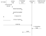
- the UE sends a PDCP layer report, a MAC Control, or a report of the physical layer to the AP2 to indicate the AP2, and the UE requests to switch to the AP3. Indicates the way, but the measurement report event triggered by the pilot or the CQI meets the threshold report. Optionally, the UE may indicate the time of the handover in the MAC Control.
- AP2 and AP3 interact to establish a forwarding tunnel (that is, Data Forwarding Tunnel ID1 and Data Forwarding Tunnel ID2). After forwarding the tunnel, AP2 sends a third message to AP3 to request to switch the UE to AP3. AP2 can request AP3 to allocate the UE. Upstream resources.
- the AP2 may also indicate the time when the AP3 sends the downlink control signaling, and if the C-RNTI needs to be re-allocated for the UE, the AP2 may instruct the AP3 to re-allocate the C-RNTI for the UE.
- the AP2 can also notify the AP3 of the uplink TEID and IP address of the AP2 through the forwarding tunnel.
- the AP3 can notify the AP2 of the downlink TEID and IP address of the AP3.
- the AP2 can send the downlink TEID address and IP address of the AP3 to the UE.
- the UE allocates uplink resources, for example, the allocated PUSCH resources, and the AP3 temporarily adds some synchronization signals to the UE.
- the AP2 sends MAC Control or Layer 3 signaling to the UE, and may carry the downlink TEID of the AP2 in the MAC Control or Layer 3 signaling.
- the UE receives the downlink control signaling sent by the AP3 through the PDCCH, and indicates in the downlink control signaling.
- the AP3 allocates the PUSCH resource to the UE, and optionally carries the C-RNTI that the AP3 reassigns to the UE in the downlink control signaling.
- the UE may send the MAC packet carrying the BSR to the AP3 through the allocated PUSCH resource, and the UE sends the handover complete information (ie, Switch Complete) to the AP1, and notifies the AP1.
- the user plane has been switched to AP3.
- the Switch Complete can carry the downlink TEID and IP address of AP3.
- AP1 can notify the S-GW/P-GW of the downlink TEID and IP address of AP3 (that is, AP1 and S-GW/P-GW interact with path withching (S-).
- the downlink data routing switch message of the GW)), the S-GW/P-GW can switch the TEID and the IP address of the downlink user plane, and then the data (Data) can be exchanged between the AP3 and the S-GW/P-GW.
- an embodiment of the present invention provides a user equipment, including a sending module 901 and a receiving module 902.
- the sending module 901 is configured to send, to the control network device or the source network device, the first information, where the first information is used to request the user equipment to switch from the source network device to the destination network device;
- the receiving module 902 is configured to receive the second information from the destination network device, the source network device, or the control network device, where the second information is used to notify the destination network device of the first uplink resource allocated by the user equipment.
- the receiving module 902 is further configured to:
- the sending module 901 After the sending module 901 sends the first information to the control network device or the source network device, the receiving the destination network device temporarily increases the sent synchronization signal, where the synchronization signal is used by the user equipment to complete downlink synchronization with the destination network device. .
- the receiving module 902 is further configured to:
- the receiving module 902 is further specifically configured to:
- the destination network device Receiving, according to the received symbol position, the destination network device temporarily increases the transmitted synchronization signal.
- the receiving module 902 is further configured to:
- the device identifier is received from the destination network device or the control network device, where the device identifier is: within the coverage of the destination network device, A unique identifier of the user equipment.
- the first uplink resource is a PUSCH resource or a PUCCH resource.
- the sending module 901 is further configured to:
- the receiving module 902 After the receiving module 902 receives the second information from the destination network device, the source network device, or the control network device, if the first uplink resource is the PUSCH resource, send the cache to the destination network device by using the first uplink resource.
- Status report or data package or,
- the receiving module 902 After the receiving module 902 receives the second information from the destination network device, the source network device, or the control network device, if the first uplink resource is the PUCCH resource, the scheduling is sent to the destination network device by using the first uplink resource. Request information.
- the sending module 901 is further configured to:
- the receiving module 902 After the receiving module 902 receives the second information from the destination network device, the source network device, or the control network device, the downlink TEID and the IP address of the destination network device are sent to the control network device.
- an embodiment of the present invention provides a network device, where the network device may be a destination network device as described above.
- the network device can include a receiving module 1001 and an allocating module 1002.
- the receiving module 1001 is configured to receive third information from the control network device or the source network device, where the third information is used to indicate that the user equipment requests to switch to the network device;
- the allocating module 1002 is configured to allocate a first uplink resource to the user equipment.
- the network device further includes a sending module, configured to:
- the sending synchronization signal is temporarily added to the user equipment, where the synchronization signal is used to complete the downlink synchronization between the user equipment and the network device.
- the sending module is further configured to:
- the allocating module 1002 allocates the first uplink resource to the user equipment
- the second information is sent to the user equipment, where the second information is used to notify the network device to allocate the first uplink to the user equipment. Resources; or
- the fourth information is sent to the control network device, where the fourth information is used to notify the network device to allocate the first Upstream resources.
- the sending module is further configured to:
- the device identifier that is allocated to the user equipment is sent to the user equipment, where the device identifier is: within the coverage of the network device, the a unique identifier of the user device; or
- the device identifier that is allocated to the user equipment is sent to the control network device, where the device identifier is: within the coverage of the network device, A unique identifier of the user equipment.
- the first uplink resource is a PUSCH resource or a PUCCH resource.
- the receiving module 1001 is further configured to:
- the allocating module 1002 allocates the first uplink resource to the user equipment, if the first uplink resource is the PUCCH resource, the scheduling request information sent by the user equipment is received by using the first uplink resource; or
- the allocating module 1002 allocates the first uplink resource to the user equipment, if the first uplink resource is the PUSCH resource, the first uplink resource is used to receive a buffer status report or a data packet sent by the user equipment.
- an embodiment of the present invention provides a network device, which may be a control network device as described above.
- the network device may include a receiving module 1101 and a sending module 1102.
- the receiving module 1101 is configured to receive first information from the user equipment, where the first information is used to indicate: The user equipment requests to switch from the source network device to the destination network device;
- the sending module 1102 is configured to send the third information to the destination network device, and request the destination network device to allocate a first uplink resource to the user equipment, where the third information is used to indicate that the user equipment requests to switch Go to the destination network device.
- the receiving module 1101 is further configured to: after the sending module 1102 requests the destination network device to allocate the first uplink resource to the user equipment, receive the fourth information sent by the destination network device.
- the fourth information is used to notify the destination network device of the first uplink resource allocated by the user equipment;
- the sending module 1102 is further configured to: send the second information to the user equipment according to the fourth information, where the second information is used to notify the destination network device to allocate the first uplink to the user equipment Resources.
- the sending module 1102 is further configured to:
- the receiving module 1101 is further configured to: after the sending module 1102 requests the destination network device to allocate the first uplink resource to the user equipment, receive the device identifier sent by the destination network device, where the device identifier is: a unique identifier of the user equipment within the coverage of the network device;
- the sending module 1102 is further configured to: send the device identifier to the user equipment.
- an embodiment of the present invention provides a network device, where the network device may be a source network device as described above.
- the network device may include a receiving module 1201 and a sending module 1202.
- the receiving module 1201 is configured to receive first information from the user equipment, where the first information is used to indicate that the user equipment requests to switch from the network device to the destination network device;
- the sending module 1202 is configured to send the third information to the destination network device, and request the destination network device to allocate a first uplink resource to the user equipment, where the third information is used to indicate that the user equipment is requested Switching from the network device to the destination network device.
- the sending module 1202 is further configured to:
- the receiving module 1201 After receiving the third information from the user equipment, the receiving module 1201 sends the uplink TEID and the IP address of the network device to the destination network device, and
- an embodiment of the present invention provides a user equipment, where the user equipment may include a memory 1301 , a processor 1302 , and a transceiver 1303 , where the memory 1301 and the transceiver 1303 are both connected to the processor 1302 . connection.
- the memory 1301 is configured to store an instruction required by the processor 1302 to perform a task
- the processor 1302 is configured to execute the instruction stored by the memory 1301, and send the first information to the control network device or the source network device by using the transceiver 1303, where the first information is used to request the user equipment to switch from the source network device to Destination network device;
- the transceiver 1303 is further configured to receive the second information from the destination network device, the source network device, or the control network device, where the second information is used to notify the destination network device of the first uplink resource allocated by the user equipment.
- the transceiver 1303 is further configured to:
- the destination network device is temporarily added to send the synchronization signal, where the synchronization signal is used by the user equipment and the destination network.
- the device completes downlink synchronization.
- the transceiver 1303 is further configured to:
- the destination network device Receiving, according to the received symbol position, the destination network device temporarily increases the transmitted synchronization signal.
- the transceiver 1303 is further configured to:
- the device identifier is received from the destination network device or the control network device, where the device identifier is: at the destination network device The unique identifier of the user equipment within the coverage.
- the first uplink resource is a PUSCH resource or a PUCCH resource.
- the processor 1302 is further configured to:
- the transceiver 13032 After the transceiver 13032 receives the second information from the destination network device, the source network device, or the control network device, if the first uplink resource is the PUSCH resource, the transceiver 1303 passes the first uplink resource to the The destination network device sends a cache status report or data packet; or,
- the transceiver 1303 After the transceiver 1303 receives the second information from the destination network device, the source network device, or the control network device, if the first uplink resource is the PUCCH resource, the transceiver 1303 passes the first uplink resource to the The destination network device sends scheduling request information.
- the processor 1302 is further configured to:
- the transceiver 1303 After the transceiver 1303 receives the second information from the destination network device, the source network device, or the control network device, the downlink TEID and the IP address of the destination network device are sent to the control network device by the transceiver 1303.
- an embodiment of the present invention provides a network device, which may be a destination network device as described above.
- the network device may include a memory 1401, a processor 1402, and a transceiver 1403, and the memory 1401 and the transceiver 1403 are respectively connected to the processor 1402.
- the memory 1401 is configured to store an instruction required by the processor 1402 to perform a task
- the transceiver 1403 is configured to receive third information from the control network device or the source network device, where the third information is used to indicate that the user equipment requests to switch to the network device;
- the processor 1402 is configured to execute an instruction stored by the memory 1401 to allocate a first uplink resource to the user equipment.
- the processor 1402 is further configured to:
- a sending synchronization signal is temporarily added to the user equipment by using the transceiver 1403, where the synchronization signal is used to complete downlink synchronization between the user equipment and the network device.
- the processor 1402 is further configured to:
- the second information is sent to the user equipment by using the transceiver 1403, where the second information is used to notify the network device to allocate the first Uplink resources; or
- the fourth information is sent to the control network device by using the transceiver 1403, where the fourth information is used to notify the network device to allocate the An uplink resource.
- the processor 1402 is further configured to:
- the device identifier that is allocated to the user equipment is sent to the user equipment by using the transceiver 1403, where the device identifier is: within the coverage of the network device, a unique identifier of the user equipment; or
- the device identifier allocated to the user equipment is sent by the transceiver 1403 to the control network device, where the device identifier is: within the coverage of the network device, A unique identifier of the user equipment.
- the first uplink resource is a PUSCH resource or a PUCCH resource.
- the transceiver 1403 is further configured to:
- the processor 1402 allocates the first uplink resource to the user equipment, if the first uplink resource is the PUCCH resource, the scheduling request information sent by the user equipment is received by using the first uplink resource; or
- the processor 1402 allocates the first uplink resource to the user equipment, if the first uplink resource is the PUSCH resource, the cache status report or the data packet sent by the user equipment is received by the first uplink resource.
- an embodiment of the present invention provides a network device according to the same inventive concept.
- the network device can be a control network device as previously described.
- the network device can include a memory 1501, a processor 1502, and a transceiver 1503, the memory 1501 and the transceiver 1503 being coupled to the processor 1502, respectively.
- the memory 1501 is configured to store an instruction required by the processor 1502 to perform a task
- the transceiver 1503 is configured to receive first information from the user equipment, where the first information is used to indicate that the user equipment requests to switch from the source network device to the destination network device;
- the processor 1502 is configured to execute the instruction stored in the memory 1501, send the third information to the destination network device by using the transceiver 1503, and request the destination network device to allocate the first uplink resource to the user equipment;
- the information is used to indicate that the user equipment requests to switch to the destination network device.
- the transceiver 1503 is further configured to: after the processor 1502 requests the destination network device to allocate the first uplink resource to the user equipment by using the transceiver 1503, receive the fourth information sent by the destination network device, where the fourth information is received.
- the first uplink resource that is used to notify the destination network device to allocate the user equipment;
- the processor 1502 is further configured to: send, by the transceiver 1503, the second information to the user equipment according to the fourth information, where the second information is used to notify the destination network device to allocate the user equipment The first uplink resource.
- the processor 1502 is further configured to:
- the transceiver 1503 After requesting the destination network device to allocate the first uplink resource to the user equipment, notify, by the transceiver 1503, the symbol location of the synchronization signal to the user equipment; wherein the synchronization signal temporarily increases the transmission for the destination network device. And a signal for the user equipment to complete downlink synchronization between the user equipment and the destination network device.
- the transceiver 1503 is further configured to: after the processor 1502 requests the destination network device to allocate the first uplink resource to the user equipment by using the transceiver 1503, receive the device identifier sent by the destination network device, where the device identifier is: Within the coverage of the destination network device, the user setting a unique identifier for the preparation;
- the processor 1502 is further configured to: send the device identifier to the user equipment by using the transceiver 1503.
- an embodiment of the present invention provides a network device, where the network device may be a source network device as described above.
- the network device can include a memory 1601, a processor 1602, and a transceiver 1603.
- the memory 1601 is configured to store an instruction required by the processor 1602 to perform a task
- the transceiver 1603 is configured to receive first information from the user equipment, where the first information is used to indicate that the user equipment requests to switch from the network device to the destination network device;
- the processor 1602 is configured to execute the instruction stored in the memory 1601, send the third information to the destination network device by using the transceiver 1603, and request the destination network device to allocate the first uplink resource to the user equipment;
- the information is used to indicate that the user equipment requests to switch from the network device to the destination network device.
- the processor 1602 is further configured to:
- the uplink TEID and the IP address of the network device are sent to the destination network device by the transceiver 1603, and
- the destination network device received by the transceiver 1603 is sent by the transceiver 1603 to the user equipment according to the uplink TEID and the downlink TEID and IP address of the destination network device that are sent by the IP address.
- an embodiment of the present invention provides a user equipment, where the user equipment may be a user equipment as described above.
- the user equipment can include a transmitter 1701 and a receiver 1702.
- the transmitter 1701 is configured to send first information to the control network device or the source network device, where the first information is used to request the user equipment to switch from the source network device to the destination network device;
- the receiver 1702 is configured to receive, by the destination network device, the source network device, or the control network device, the second information, where the second information is used to notify the destination network device of the first uplink resource allocated by the user equipment.
- the receiver 1702 is further configured to:
- the destination network device After the transmitter 1701 sends the first information to the control network device or the source network device, the destination network device receives the synchronization signal that is temporarily sent, and the synchronization signal is used by the user equipment to complete downlink synchronization with the destination network device. .
- the receiver 1702 is specifically configured to:
- the destination network device Receiving, according to the received symbol position, the destination network device temporarily increases the transmitted synchronization signal.
- the receiver 1702 is further configured to:
- the device identifier is received from the destination network device or the control network device, where the device identifier is: within the coverage of the destination network device, A unique identifier of the user equipment.
- the first uplink resource is a PUSCH resource or a PUCCH resource.
- the transmitter 1701 is further configured to:
- the receiver 1702 After the receiver 1702 receives the second information from the destination network device, the source network device, or the control network device, if the first uplink resource is the PUSCH resource, send the cache to the destination network device by using the first uplink resource. Status report or data package; or,
- the receiver 1702 After the receiver 1702 receives the second information from the destination network device, the source network device, or the control network device, if the first uplink resource is the PUCCH resource, the scheduling is sent to the destination network device by using the first uplink resource. Request information.
- the transmitter 1701 is further configured to:
- the receiver 1702 After the receiver 1702 receives the second information from the destination network device, the source network device, or the control network device, the downlink TEID and the IP address of the destination network device are sent to the control network device.
- an embodiment of the present invention provides a network device, which may be a destination network device as described above.
- the network device may include each other Connected receiver 1801 and processor 1802.
- the receiver 1801 is configured to receive third information from the control network device or the source network device, where the third information is used to indicate that the user equipment requests to switch to the network device;
- the processor 1802 is configured to allocate a first uplink resource to the user equipment.
- the network device further includes a transmitter 1803 connected to the processor 1802, configured to:
- the user equipment After the processor 1802 allocates the first uplink resource to the user equipment, the user equipment is temporarily added with a sending synchronization signal, where the synchronization signal is used to complete the downlink synchronization between the user equipment and the network device.
- the network device further includes a transmitter 1803, configured to:
- the second information is sent to the user equipment, where the second information is used to notify the network device to allocate the first uplink to the user equipment. Resources; or
- the processor 1802 allocates the first uplink resource to the user equipment, sending, to the control network device, fourth information, where the fourth information is used to notify the network device to allocate the first Upstream resources.
- the network device further includes a transmitter 1803, configured to:
- the device identifier that is allocated to the user equipment is sent to the user equipment, where the device identifier is: within the coverage of the network device, the a unique identifier of the user device; or
- the device identifier that is allocated to the user equipment is sent to the control network device, where the device identifier is: within the coverage of the network device, A unique identifier of the user equipment.
- the first uplink resource is a PUSCH resource or a PUCCH resource.
- the receiver 1801 is further configured to:
- the processor 1802 allocates the first uplink resource to the user equipment, if the first uplink resource is the PUCCH resource, the first uplink resource is used to receive the tone sent by the user equipment. Request information; or
- the processor 1802 allocates the first uplink resource to the user equipment, if the first uplink resource is the PUSCH resource, the buffer status report or data packet sent by the user equipment is received by the first uplink resource.
- an embodiment of the present invention provides a network device, which may be a control network device as described above.
- the network device can include a receiver 1901 and a transmitter 1902.
- the receiver 1901 receives first information from the user equipment, where the first information is used to indicate that the user equipment requests to switch from the source network device to the destination network device;
- the sender 1902 is configured to send the third information to the destination network device, and request the destination network device to allocate a first uplink resource to the user equipment, where the third information is used to indicate that the user equipment requests to switch Go to the destination network device.
- the receiver 1902 is further configured to: after the transmitter 1901 requests the destination network device to allocate the first uplink resource to the user equipment, receive fourth information from the destination network device, where the fourth information is used to notify the The first uplink resource allocated by the destination network device to the user equipment;
- the transmitter 1901 is further configured to: send the second information to the user equipment according to the fourth information, where the second information is used to notify the destination network device to allocate the first uplink to the user equipment Resources.
- the transmitter 1901 is further configured to:
- the receiver 1902 is further configured to: after the transmitter 1901 requests the destination network device to allocate the first uplink resource to the user equipment, receive the device identifier from the destination network device, where the device The identifier is: a unique identifier of the user equipment within the coverage of the destination network device;
- the transmitter 1901 is further configured to: send the device identifier to the user equipment.
- an embodiment of the present invention provides a network device, which may be a source network device as described above.
- the network device can include a receiver 2001 and a transmitter 2002.
- the receiver 2001 is configured to receive first information from the user equipment, where the first information is used to indicate that the user equipment requests to switch from the network device to the destination network device;
- the transmitter 2002 is configured to send the third information to the destination network device, and request the destination network device to allocate a first uplink resource to the user equipment, where the third information is used to indicate that the user equipment requests The network device switches to the destination network device.
- the transmitter 2002 is further configured to:
- the destination network device when the user equipment can send the first information for requesting the handover, can allocate the first uplink resource to the user equipment, and the user can receive the notification destination network.
- the steps that need to be performed when switching reduce the time required for user equipment switching, and improve the switching efficiency of the user equipment.
- the disclosed system, apparatus, and method may be implemented in other manners.
- the device embodiments described above are merely illustrative.
- the division of the unit or unit is only a logical function division.
- there may be another division manner for example, multiple units or components may be used. Combinations can be integrated into another system, or some features can be ignored or not executed.
- the mutual coupling or direct coupling or communication connection shown or discussed may be an indirect coupling or communication connection through some interface, device or unit, and may be in an electrical, mechanical or other form.
- the units described as separate components may or may not be physically separated, and the components displayed as units may or may not be physical units, that is, may be located in one place, or may be distributed to multiple network units. Some or all of the units may be selected according to actual needs to achieve the purpose of the solution of the embodiment.
- each functional unit in each embodiment of the present application may be integrated into one processing unit, or each unit may exist physically separately, or two or more units may be integrated into one unit.
- the above integrated unit can be implemented in the form of hardware or in the form of a software functional unit.
- the integrated unit if implemented in the form of a software functional unit and sold or used as a standalone product, may be stored in a computer readable storage medium.
- a computer readable storage medium A number of instructions are included to cause a computer device (which may be a personal computer, a server, or a network device, etc.) or a processor to execute all or part of the steps of the methods described in various embodiments of the present application.
- the foregoing storage medium includes: a U disk, a mobile hard disk, a ROM (Read-Only Memory), a RAM (Random Access Memory), a disk or an optical disk, and the like, which can store program codes. .
Abstract
La présente invention appartient au domaine technique des communications. Elle concerne un procédé et un dispositif de commutation d'équipement d'utilisateur, utilisés pour résoudre le problème technique lié à la faible efficacité de commutation lorsqu'un équipement d'utilisateur exécute une commutation. Dans des modes de réalisation de la présente invention, lors de l'exécution d'une commutation, un équipement d'utilisateur peut transmettre des premières informations utilisées pour demander une commutation, ce qui permet à un dispositif de réseau cible d'attribuer une première ressource de liaison montante à l'équipement d'utilisateur. Dans le procédé, l'équipement d'utilisateur est autorisé à transmettre des informations au dispositif de réseau cible au moyen de la première ressource de liaison montante, ce qui supprime la nécessité d'entrer en concurrence pour des ressources de liaison montante en exécutant un processus d'accès aléatoire, et améliore l'efficacité de commutation de l'équipement d'utilisateur.
Priority Applications (9)
| Application Number | Priority Date | Filing Date | Title |
|---|---|---|---|
| AU2015396026A AU2015396026B2 (en) | 2015-05-27 | 2015-05-27 | User equipment handover method, and device |
| EP19155380.9A EP3550887B1 (fr) | 2015-05-27 | 2015-05-27 | Procédé et dispositif de transfert d'équipement utilisateur |
| EP15892933.1A EP3293940B1 (fr) | 2015-05-27 | 2015-05-27 | Procédé et dispositif de commutation d'équipement d'utilisateur |
| CN201580068028.1A CN107113335B (zh) | 2015-05-27 | 2015-05-27 | 一种用户设备切换方法及设备 |
| PCT/CN2015/079986 WO2016187852A1 (fr) | 2015-05-27 | 2015-05-27 | Procédé et dispositif de commutation d'équipement d'utilisateur |
| CN202010656838.1A CN111818601B (zh) | 2015-05-27 | 2015-05-27 | 一种用户设备切换方法及设备 |
| US15/822,776 US10791484B2 (en) | 2015-05-27 | 2017-11-27 | User equipment handover method and device |
| AU2020200443A AU2020200443B2 (en) | 2015-05-27 | 2020-01-22 | User equipment handover method, and device |
| US17/011,691 US11503520B2 (en) | 2015-05-27 | 2020-09-03 | User equipment handover method and device |
Applications Claiming Priority (1)
| Application Number | Priority Date | Filing Date | Title |
|---|---|---|---|
| PCT/CN2015/079986 WO2016187852A1 (fr) | 2015-05-27 | 2015-05-27 | Procédé et dispositif de commutation d'équipement d'utilisateur |
Related Child Applications (1)
| Application Number | Title | Priority Date | Filing Date |
|---|---|---|---|
| US15/822,776 Continuation US10791484B2 (en) | 2015-05-27 | 2017-11-27 | User equipment handover method and device |
Publications (1)
| Publication Number | Publication Date |
|---|---|
| WO2016187852A1 true WO2016187852A1 (fr) | 2016-12-01 |
Family
ID=57392418
Family Applications (1)
| Application Number | Title | Priority Date | Filing Date |
|---|---|---|---|
| PCT/CN2015/079986 WO2016187852A1 (fr) | 2015-05-27 | 2015-05-27 | Procédé et dispositif de commutation d'équipement d'utilisateur |
Country Status (5)
| Country | Link |
|---|---|
| US (2) | US10791484B2 (fr) |
| EP (2) | EP3293940B1 (fr) |
| CN (2) | CN111818601B (fr) |
| AU (2) | AU2015396026B2 (fr) |
| WO (1) | WO2016187852A1 (fr) |
Cited By (1)
| Publication number | Priority date | Publication date | Assignee | Title |
|---|---|---|---|---|
| JP7349986B2 (ja) | 2018-02-07 | 2023-09-25 | オッポ広東移動通信有限公司 | セルハンドオーバの方法、ネットワークノードおよび端末機器 |
Families Citing this family (4)
| Publication number | Priority date | Publication date | Assignee | Title |
|---|---|---|---|---|
| CN107634924B (zh) * | 2016-07-18 | 2020-08-11 | 中兴通讯股份有限公司 | 同步信号的发送、接收方法及装置、传输系统 |
| CN110557268B (zh) * | 2018-05-31 | 2021-01-29 | 华为技术有限公司 | 对以太网帧的发送进行控制的方法和装置 |
| CN117044298A (zh) * | 2021-04-01 | 2023-11-10 | 华为技术有限公司 | 基于多发rach的sdt方案的增强 |
| CN117044297A (zh) * | 2021-04-01 | 2023-11-10 | 华为技术有限公司 | 用于在进行中的通信会话期间增强小区重选的设备和方法 |
Citations (1)
| Publication number | Priority date | Publication date | Assignee | Title |
|---|---|---|---|---|
| CN102282890A (zh) * | 2009-01-16 | 2011-12-14 | 夏普株式会社 | 移动站装置、基站装置、越区切换方法以及移动通信系统 |
Family Cites Families (30)
| Publication number | Priority date | Publication date | Assignee | Title |
|---|---|---|---|---|
| CN100463564C (zh) * | 2005-09-12 | 2009-02-18 | 大唐移动通信设备有限公司 | 接力切换失败后回切的方法 |
| CN101047622B (zh) * | 2006-03-29 | 2010-05-12 | 华为技术有限公司 | 一种对系统资源进行调度的方法 |
| GB0702169D0 (en) * | 2007-02-05 | 2007-03-14 | Nec Corp | Resource Allocation |
| US8218500B2 (en) * | 2007-04-30 | 2012-07-10 | Texas Instruments Incorporated | Pre-synchronization method for hard handovers in wireless networks |
| EP2187668A4 (fr) * | 2007-08-07 | 2014-01-22 | Sharp Kk | Système de communication mobile, dispositif de station mobile, dispositif de station de base, procédé de communication et procédé de commande de communication |
| CN105099597B (zh) * | 2009-03-13 | 2018-02-02 | Lg电子株式会社 | 考虑上行链路/下行链路分量载波设定所执行的切换 |
| CN101932052B (zh) * | 2009-06-23 | 2016-08-24 | 华为技术有限公司 | 一种切换方法、用户终端及网络侧设备 |
| JP5078954B2 (ja) * | 2009-08-06 | 2012-11-21 | シャープ株式会社 | 移動局装置、基地局装置、無線通信システムおよび無線通信方法 |
| CN101998553B (zh) * | 2009-08-14 | 2013-07-31 | 电信科学技术研究院 | 上行资源的分配方法和设备 |
| CN102577219B (zh) * | 2009-10-05 | 2016-06-29 | 瑞典爱立信有限公司 | Lte-advanced中用于载波聚合的pucch资源分配 |
| EP3442308B1 (fr) * | 2009-11-02 | 2020-03-25 | Kyocera Corporation | Système de radiocommunication, station de base à faible puissance, station de base à haute puissance, terminal radio et procédé de communication radio |
| CN101715237B (zh) * | 2009-11-05 | 2015-09-16 | 中兴通讯股份有限公司 | 基于竞争的上行传输方法及装置 |
| CN102170667B (zh) * | 2010-02-25 | 2013-02-27 | 中兴通讯股份有限公司 | 一种实现基站间切换的方法、系统及基站装置 |
| KR101750824B1 (ko) * | 2010-06-07 | 2017-07-04 | 삼성전자주식회사 | 계층적 셀 구조를 가지는 무선통신 시스템에서 간섭 제어 장치 및 방법 |
| US8578035B2 (en) * | 2010-09-27 | 2013-11-05 | Telefonaktiebolaget Lm Ericsson (Publ) | Technique for relocating a serving gateway associated to a user equipment |
| KR101671261B1 (ko) * | 2010-10-08 | 2016-11-17 | 삼성전자주식회사 | 이기종 망 시스템에서 소형 셀의 커버리지 확장을 지원하기 위한 장치 및 방법 |
| CN102271374A (zh) | 2011-09-14 | 2011-12-07 | 北京邮电大学 | 一种基于目标小区预承载的td-lte通信系统的快速切换方法 |
| US8982841B2 (en) * | 2011-10-27 | 2015-03-17 | Spidercloud Wireless, Inc. | Long term evolution architecture and mobility |
| WO2013170484A1 (fr) * | 2012-05-18 | 2013-11-21 | 华为技术有限公司 | Procédé de notification d'informations de configuration de cellules, et appareil et système associés |
| ES2938769T3 (es) * | 2012-08-02 | 2023-04-14 | Ericsson Telefon Ab L M | Un nodo y un método para proporcionar una interfaz entre nodos B mejorados (eNB) |
| CN104255056B (zh) * | 2012-10-19 | 2018-11-20 | 华为技术有限公司 | 切换方法和设备 |
| WO2014071561A1 (fr) * | 2012-11-07 | 2014-05-15 | Telefonaktiebolaget L M Ericsson (Publ) | Procédé et station de base destinés à une sélection de cellule |
| CN103945471B (zh) * | 2013-01-21 | 2019-01-22 | 电信科学技术研究院 | 一种小区切换方法及装置 |
| WO2014198295A1 (fr) * | 2013-06-11 | 2014-12-18 | Nokia Solutions And Networks Oy | Mobilite en couches |
| CN104521252B (zh) * | 2013-08-06 | 2019-04-05 | 华为技术有限公司 | 一种umts到lte的网络切换方法、设备及系统 |
| CN104469859B (zh) * | 2013-09-23 | 2018-06-01 | 联芯科技有限公司 | 一种提高数据传输性能的方法和系统 |
| US10034196B2 (en) * | 2013-09-30 | 2018-07-24 | Alcatel Lucent | Methods, systems and devices for improving discontinuous reception in wideband wireless networks |
| WO2015047051A1 (fr) * | 2013-09-30 | 2015-04-02 | Lg Electronics Inc. | Procédé pour déterminer une configuration de commande de ressource radio dans un système de communication sans fil prenant en charge une double connectivité, et appareil associé |
| US9313698B2 (en) * | 2013-10-11 | 2016-04-12 | Blackberry Limited | Method and apparatus for handover in heterogeneous cellular networks |
| US10772021B2 (en) * | 2014-12-05 | 2020-09-08 | Qualcomm Incorporated | Low latency and/or enhanced component carrier discovery for services and handover |
-
2015
- 2015-05-27 CN CN202010656838.1A patent/CN111818601B/zh active Active
- 2015-05-27 AU AU2015396026A patent/AU2015396026B2/en active Active
- 2015-05-27 WO PCT/CN2015/079986 patent/WO2016187852A1/fr active Application Filing
- 2015-05-27 CN CN201580068028.1A patent/CN107113335B/zh active Active
- 2015-05-27 EP EP15892933.1A patent/EP3293940B1/fr active Active
- 2015-05-27 EP EP19155380.9A patent/EP3550887B1/fr active Active
-
2017
- 2017-11-27 US US15/822,776 patent/US10791484B2/en active Active
-
2020
- 2020-01-22 AU AU2020200443A patent/AU2020200443B2/en active Active
- 2020-09-03 US US17/011,691 patent/US11503520B2/en active Active
Patent Citations (1)
| Publication number | Priority date | Publication date | Assignee | Title |
|---|---|---|---|---|
| CN102282890A (zh) * | 2009-01-16 | 2011-12-14 | 夏普株式会社 | 移动站装置、基站装置、越区切换方法以及移动通信系统 |
Cited By (1)
| Publication number | Priority date | Publication date | Assignee | Title |
|---|---|---|---|---|
| JP7349986B2 (ja) | 2018-02-07 | 2023-09-25 | オッポ広東移動通信有限公司 | セルハンドオーバの方法、ネットワークノードおよび端末機器 |
Also Published As
| Publication number | Publication date |
|---|---|
| CN111818601A (zh) | 2020-10-23 |
| CN111818601B (zh) | 2022-04-12 |
| AU2015396026A1 (en) | 2018-01-04 |
| AU2020200443B2 (en) | 2021-11-04 |
| EP3293940B1 (fr) | 2019-04-24 |
| US11503520B2 (en) | 2022-11-15 |
| EP3550887B1 (fr) | 2023-08-16 |
| EP3293940A4 (fr) | 2018-05-23 |
| US20200404550A1 (en) | 2020-12-24 |
| EP3550887A1 (fr) | 2019-10-09 |
| CN107113335A (zh) | 2017-08-29 |
| AU2020200443A1 (en) | 2020-02-13 |
| EP3293940A1 (fr) | 2018-03-14 |
| CN107113335B (zh) | 2020-07-24 |
| US10791484B2 (en) | 2020-09-29 |
| US20180084462A1 (en) | 2018-03-22 |
| AU2015396026B2 (en) | 2019-10-24 |
Similar Documents
| Publication | Publication Date | Title |
|---|---|---|
| US11184886B2 (en) | Method, base station, and user equipment for implementing carrier aggregation | |
| KR101660859B1 (ko) | 주 보조 셀 변경 방법 및 기지국 | |
| US11503520B2 (en) | User equipment handover method and device | |
| JP6029978B2 (ja) | 一種の端末識別子の使用方法、システム、設備及び端末 | |
| WO2016004828A1 (fr) | Station de base, équipement utilisateur et procédé associé | |
| WO2013139161A1 (fr) | Procédé et appareil de planification de ressources dans un réseau sans fil | |
| WO2016049806A1 (fr) | Procédé et appareil de distribution | |
| JP6697095B2 (ja) | 通信方法と通信装置 | |
| CN111316755B (zh) | 使能同时使用多种蜂窝网络技术 | |
| WO2019233205A1 (fr) | Procédé et appareil de configuration d'une largeur de bande de transmission, et dispositif | |
| WO2016026117A1 (fr) | Attribution de ressources et procédé et appareil de transmission de service | |
| WO2017114218A1 (fr) | Procédé et dispositif de division de ressource | |
| JP7392844B2 (ja) | 車両通信サービスの通信方法、装置及び通信システム | |
| WO2023227090A1 (fr) | Procédé et appareil de mise à jour de cellule pour groupe de cellules secondaires, et support de stockage | |
| WO2014110825A1 (fr) | Procédé et appareil de planification de données de liaison montante dans une agrégation de porteuses |
Legal Events
| Date | Code | Title | Description |
|---|---|---|---|
| 121 | Ep: the epo has been informed by wipo that ep was designated in this application |
Ref document number: 15892933 Country of ref document: EP Kind code of ref document: A1 |
|
| NENP | Non-entry into the national phase |
Ref country code: DE |
|
| WWE | Wipo information: entry into national phase |
Ref document number: 2015892933 Country of ref document: EP |
|
| ENP | Entry into the national phase |
Ref document number: 2015396026 Country of ref document: AU Date of ref document: 20150527 Kind code of ref document: A |