WO2016186551A1 - Pixel processing and encoding - Google Patents
Pixel processing and encoding Download PDFInfo
- Publication number
- WO2016186551A1 WO2016186551A1 PCT/SE2016/050432 SE2016050432W WO2016186551A1 WO 2016186551 A1 WO2016186551 A1 WO 2016186551A1 SE 2016050432 W SE2016050432 W SE 2016050432W WO 2016186551 A1 WO2016186551 A1 WO 2016186551A1
- Authority
- WO
- WIPO (PCT)
- Prior art keywords
- color
- pixel
- value
- representation
- threshold value
- Prior art date
Links
Classifications
-
- H—ELECTRICITY
- H04—ELECTRIC COMMUNICATION TECHNIQUE
- H04N—PICTORIAL COMMUNICATION, e.g. TELEVISION
- H04N19/00—Methods or arrangements for coding, decoding, compressing or decompressing digital video signals
- H04N19/10—Methods or arrangements for coding, decoding, compressing or decompressing digital video signals using adaptive coding
- H04N19/169—Methods or arrangements for coding, decoding, compressing or decompressing digital video signals using adaptive coding characterised by the coding unit, i.e. the structural portion or semantic portion of the video signal being the object or the subject of the adaptive coding
- H04N19/182—Methods or arrangements for coding, decoding, compressing or decompressing digital video signals using adaptive coding characterised by the coding unit, i.e. the structural portion or semantic portion of the video signal being the object or the subject of the adaptive coding the unit being a pixel
-
- H—ELECTRICITY
- H04—ELECTRIC COMMUNICATION TECHNIQUE
- H04N—PICTORIAL COMMUNICATION, e.g. TELEVISION
- H04N19/00—Methods or arrangements for coding, decoding, compressing or decompressing digital video signals
- H04N19/10—Methods or arrangements for coding, decoding, compressing or decompressing digital video signals using adaptive coding
- H04N19/102—Methods or arrangements for coding, decoding, compressing or decompressing digital video signals using adaptive coding characterised by the element, parameter or selection affected or controlled by the adaptive coding
- H04N19/117—Filters, e.g. for pre-processing or post-processing
-
- H—ELECTRICITY
- H04—ELECTRIC COMMUNICATION TECHNIQUE
- H04N—PICTORIAL COMMUNICATION, e.g. TELEVISION
- H04N19/00—Methods or arrangements for coding, decoding, compressing or decompressing digital video signals
- H04N19/10—Methods or arrangements for coding, decoding, compressing or decompressing digital video signals using adaptive coding
- H04N19/169—Methods or arrangements for coding, decoding, compressing or decompressing digital video signals using adaptive coding characterised by the coding unit, i.e. the structural portion or semantic portion of the video signal being the object or the subject of the adaptive coding
- H04N19/186—Methods or arrangements for coding, decoding, compressing or decompressing digital video signals using adaptive coding characterised by the coding unit, i.e. the structural portion or semantic portion of the video signal being the object or the subject of the adaptive coding the unit being a colour or a chrominance component
-
- H—ELECTRICITY
- H04—ELECTRIC COMMUNICATION TECHNIQUE
- H04N—PICTORIAL COMMUNICATION, e.g. TELEVISION
- H04N19/00—Methods or arrangements for coding, decoding, compressing or decompressing digital video signals
- H04N19/85—Methods or arrangements for coding, decoding, compressing or decompressing digital video signals using pre-processing or post-processing specially adapted for video compression
- H04N19/86—Methods or arrangements for coding, decoding, compressing or decompressing digital video signals using pre-processing or post-processing specially adapted for video compression involving reduction of coding artifacts, e.g. of blockiness
-
- H—ELECTRICITY
- H04—ELECTRIC COMMUNICATION TECHNIQUE
- H04N—PICTORIAL COMMUNICATION, e.g. TELEVISION
- H04N19/00—Methods or arrangements for coding, decoding, compressing or decompressing digital video signals
- H04N19/46—Embedding additional information in the video signal during the compression process
Definitions
- the present embodiments generally relate to processing and encoding of pixels in a picture, and in particular to such processing and encoding that improves encoding efficiency without significant deterioration of perceived quality.
- a combination of a highly non-linear transfer function, 4:2:0 or 4:2:2 subsampling and non-constant luminance ordering gives rise to severe artifacts in saturated colors, i.e. color values close to the edge of the color gamut.
- An example is described in Annex B, where changes between two colors of similar luminance can result in a reconstructed image or picture with very different luminances.
- Y'Cb'Cr' or R'G'B' for the last step of the signal to the display.
- the HDMI (High Definition Multimedia Interface) standard has recently adopted the use of Y'Cb'Cr' 4:2:0 using ST 2084 for transmission of images from the set-top box to the TV as specified in CEA-861.3 [4]. This means that even if the encoding is done in some other color representation, after decoding it still needs to be converted to Y'Cb'Cr' 4:2:0, which will give rise to artifacts.
- An aspect of the embodiments relates to a method of processing pixels in a picture of a video sequence comprising multiple pictures.
- the method comprises identifying a pixel to be processed in the picture for which a variation in a linear representation of a color of the pixel that is smaller than a first threshold value results in a variation in a non-linear representation of the color that is larger than a second threshold value.
- the variation in the linear representation of the color also results in a variation in a luminance and chrominance based representation of the color that is smaller than a third threshold value.
- the method also comprises processing the identified pixel by modifying a value of at least one color component of the pixel.
- Another aspect of the embodiments relates to a device for processing pixels in a picture of a video sequence comprising multiple pictures.
- the device is configured to identify a pixel to be processed in the picture for which a variation in a linear representation of a color of the pixel that is smaller than a first threshold value results in a variation in a non-linear representation of the color that is larger than a second threshold value.
- the variation in the linear representation of the color also results in a variation in a luminance and chrominance based representation of the color that is smaller than a third threshold value.
- the device is also configured to process the identified pixel by modifying a value of at least one color component of the pixel.
- a further aspect of the embodiments relates to a device for processing a pixel in a picture of a video sequence comprising multiple pictures.
- the device comprises a determining unit for identifying a pixel to be processed in the picture for which a variation in a linear representation of a color of the pixel that is smaller than a first threshold value results in a variation in a non-linear representation of the color that is larger than a second threshold value.
- the variation in the linear representation of the color also results in a variation in a luminance and chrominance based representation of the color that is smaller than a third threshold value.
- the device also comprises a pixel processor for processing the identified pixel by modifying a value of at least one color component of the pixel.
- the device comprises a determining unit for identifying a pixel to be processed in the picture for which a variation in a linear representation of a color of the pixel that is smaller than a first threshold value results in a variation in a non-linear representation of the color that is larger than a second threshold value.
- the variation in the linear representation of the color also results in a variation in a luminance and chrominance based representation of the color that is smaller than a third threshold value.
- the device also comprises a pixel processor for processing the identified pixel by modifying a value of at least one color component in the linear representation of the color.
- the device further comprises a converter for converting the linear representation of the color into a non- linear representation of the color of the pixel.
- the device additionally comprises an encoder for encoding the non-linear representation of the color.
- a further aspect of the embodiments relates to a device for encoding a pixel in a picture of a video sequence comprising multiple pictures.
- the device comprises a processor and a memory comprising instructions executable by the processor.
- the processor is operative to identify a pixel to be processed in the picture for which a variation in a linear representation of a color of the pixel that is smaller than a first threshold value results in a variation in a non-linear representation of the color that is larger than a second threshold value.
- the variation in the linear representation of the color also results in a variation in a luminance and chrominance based representation of the color that is smaller than a third threshold value.
- the processor is also operative to process the identified pixel by modifying a value of at least one color component in the linear representation of the color.
- the processor is further operative to convert the linear representation of the color into a non-linear representation of the color of the pixel.
- the processor is additionally operative to encode the non-linear representation of the color.
- the variation in the linear representation of the color also results in a variation in a luminance and chrominance based representation of the color that is smaller than a third threshold value.
- the processor is also caused to process the identified pixel by modifying a value of at least one color component of the pixel.
- a related aspect of the embodiments defines a carrier comprising a computer program according to above.
- the carrier is one of an electronic signal, an optical signal, an electromagnetic signal, a magnetic signal, an electric signal, a radio signal, a microwave signal, or a computer-readable storage medium.
- a further aspect of the embodiments relates to a signal representing an encoded version of a pixel in a picture of a video sequence comprising multiple pictures.
- the encoded version comprises an encoded non-linear representation of a color of the pixel according to any of the embodiments.
- the processing of the embodiments achieves a selected denoising of color components for pixels having colors meeting defined criteria.
- the denoising results in a color representation of the pixel that is cheaper to encode yet not visibly different from the original pixel, i.e. without any denoising, for the naked eye.
- Fig. 1 is a flow chart illustrating a method of processing pixels in a picture according to an embodiment
- Fig. 2 is a flow chart illustrating an embodiment of the identifying step in Fig. 1 ;
- Fig. 3 is a flow chart illustrating a method of processing pixels in a picture according to another embodiment
- Fig. 4 is a flow chart illustrating an embodiment of the processing step in Fig. 1
- Fig. 5 is a flow chart illustrating another embodiment of the processing step in Fig. 1
- Fig. 6 is a flow chart illustrating a further embodiment of the processing step in Fig. 1
- Fig. 7 is a flow chart illustrating an additional step of the method shown in Fig. 1 to form a method of encoding a pixel according to an embodiment
- Fig. 8 illustrates a tone-mapped version of an original image (A), linear luminance Y treated with PQ(.) to bring out details (B), u' (C) and v' (D);
- Fig. 9 illustrates the R'G'B' version of the image, i.e. after application of the non-linear PQ(.) function to each component (A), the Y' component (B), Cb' (C) and Cr' (D);
- Fig. 10 illustrates the same Y' as in Fig. 9B (A), subsampled Cb' component (B), subsampled Cr' component (C) and a tonemapped version of the resulting image (D);
- Fig. 11 illustrates the PQ(Y) of the anchor image (A), u' component (B) and v' component (C);
- Fig. 12 illustrates the corrected Y' using the Ajusty method of Annex A (A), Cb' component (B), Cr' component (C), PQ(Y) and a tonemapped version of the resulting image (E);
- Fig. 13 illustrates a plot of the function PQ(x).
- Fig. 14 illustrates the problem area identified using a simple pseudo code
- Fig. 15 illustrates the green component (PQ(G)) before blurring (A), after blurring (B) and the resulting image when selecting between the original and the blurred version (C);
- Fig. 16 illustrates an original image (tonemapped) (A), using proposed filtering (B), using Ajusty method of Annex A (C) and using proposed filtering followed by the Ajusty method of Annex A (D);
- Fig. 17 illustrates Cb' of the Ajusty method of Annex A (A), Cr' of the Ajusty method of Annex A (B), Cb' of the proposed scheme (C) and Ci ⁇ of the proposed scheme (D);
- Fig. 18 illustrates the Y' component using the Ajusty method of Annex A (A) and the Y' component using the proposed scheme followed by the Ajusty method of Annex A (B);
- Fig. 19 illustrates a tonemapped original image (A), tonemapped anchor image (B) and averaging G over pixels that have a G that would not affect the PQ(Y) or u'v' more than 4 steps for the instable pixels, i.e. First case pixels (C);
- Fig. 20 is a flow chart illustrating a method according to one embodiment;
- Fig. 21 is a schematic illustration of hardware implementations of a device or converter according to the embodiments
- Fig. 22 is a schematic illustration of an implementation of a device or converter according to the embodiments with a processor and a memory;
- Fig. 23 is a schematic illustration of a user equipment according to an embodiment
- Fig. 24 is a schematic illustration of an implementation of a device according to the embodiments with function modules
- Fig. 25 schematically illustrate a distributed implementation of the embodiments among multiple network devices
- Fig. 26 is a schematic illustration of an example of a wireless communication system with one or more cloud-based network devices according to an embodiment
- Fig. 27 illustrates an embodiment of deriving the corrected Y'
- Fig. 28 is a diagram illustrating that there can be different linearizations in different color areas; Fig. 29 illustrates Barten's curve for contrast sensitivity; and Fig. 30 illustrates a comparison between Rec709 and BT.2020 color gamuts.
- a traditional encoding chain involves feeding pixels of incoming linear RGB light, typically ranging from 0 to 10,000 cd/m 2 , to an inverse transfer function, which results in new pixel values between 0 and 1. After this, the pixels undergo color transformation resulting in a luma component Y' and two chroma components Cb', Cr ⁇ Then, the two chroma components are subsampled, such as to 4:2:0 or 4:2:2. After decoding, the 4:2:0 or 4:2:2 sequences are upsampled to 4:4:4, inverse color transformed and finally a transfer function gives back pixels of linear light that can be output on a monitor.
- a color space or color domain is the type and number of colors that originate from the combinations of color components of a color model.
- a color model is an abstract configuration describing the way colors can be represented as tuples of numbers, i.e. color components.
- the color components have several distinguishing features such as the component type, e.g. hue, and its unit, e.g. degrees or percentage, or the type of scale, e.g. linear or non-linear, and its intended number of values referred to as the color depth or bit depth.
- Non-limiting, but illustrative, color spaces that are commonly used for pixels in pictures and videos include the red, green, blue (RGB) color space, the luma, chroma blue and chroma red (YCbCr, sometimes denoted Y'CbCr, Y'Cb'Cr', YCBCR, Y'CBCR or Y'CB'CR') color space and the luminance and chrominances (XYZ) color space.
- RGB red, green, blue
- YCbCr chroma blue and chroma red
- YCbCr sometimes denoted Y'CbCr, Y'Cb'Cr', YCBCR, Y'CBCR or Y'CB'CR'
- XYZ luminance and chrominances
- RGB Linear RGB values, where each value is proportional to the cd/m 2 ("number of photons").
- XYZ Linear XYZ values, where each value is a linear combination of RGB. Y is called luminance and loosely speaking reflects well what the eye perceives as "brightness" and XZ contains chrominance. XYZ is sometimes referred to as the CIE 1931 color space.
- PQ(Y) A non-linear representation where the non-linear function PQ( ⁇ ) has been applied to the linear luminance Y.
- An example of a non-linear function is the Perceptual Quantizer (PQ), the inverse of which is defined in equation A1.
- PQ(Y) is not to be confused with Y'. Since PQ(.) is based on Barten's curve, a small step in PQ(Y) is equivalent to a small step in perceived luminance.
- R'G'B' Non-linear RGB values.
- 'Cb'C A non-linear representation where each value is a linear combination of R', G' and B'.
- Y' is called “luma”, and Cb' and Cr' are collectively called “chroma”. This is to distinguish Y' from luminance, since Y' also contains some chrominance, and Cb' and Ci ⁇ also contain some luminance.
- ICtCp A representation of color designed for High Dynamic Range (HDR) and Wide Color Gamut (WCG) imagery and is intended as an alternative to Y'Cb'Cr ⁇ I represents intensity and is representation of luma information, whereas CtCp carries chroma information.
- uV A non-linear representation of chrominance, i.e. is a non-linear function of xy. It is supposed to be more perceptually uniform, meaning that a small step in uV will be equally perceptible regardless of which chrominance we are at. Just as for xy, a monochromatic laser will always have the same uV coordinates no matter what intensity it has.
- PQ(Y)xy and PQ(Y)uV Representations of color where PQ(Y) contains all the luminance and xy or uV all the chrominance. From PQ(Y) it is possible to extract Y, and from Y, x, and y or Y, u' and v' it is possible to extract XYZ which can be transformed to RGB.
- LogLuv Uses the logarithm of the luminance Y and the (u', v') chromaticity coordinates (without logarithm) in order to provide a perceptually uniform color space.
- the present embodiments propose a technology to avoid too much variation in a non-linear representation of the color of a pixels, such as in Cb' and Cr', as an alternative to or in combination with changing the luma values Y' to correct the luminance.
- variation of Cb' and Cr' is desired, since it reflects the visible signal that is encoded.
- the variation in Cb' and Cr' does not reflect changes that are visually noticeable.
- the pixels where it is preferred to lower the variation i.e. denoise, are often situated along the edge of the color gamut.
- the embodiments treat the original signal in a manner so that the differences between pixel colors in a first case, when the differences are not visible or hard to see, are removed, whereas the color differences in a second case, when the differences are visible, are kept.
- the Y b r" representation of the pixel colors will be varying less or not at all, needing fewer bits or no bits to code, in the first case, where the variation is not visible or hard to see, whereas it will be varying in the second case, where the variation is actually visible.
- the differences should not be visible in either luminance or chrominance. Only then is it safe to change the data without a risk for any visual artifacts. However, a change in luminance is typically worse than a change in chrominance, so in some cases the difference should at least not be visible in luminance.
- the differences in the first case are removed by reducing the variability of components close to 0 when at least one of the other components is far from zero, to avoid variability in Y'Cb'Cr' that cannot be seen anyway, and which can create problems during the encoding.
- Fig. 1 is a flow chart illustrating a method of processing pixels in a picture of a video sequence comprising multiple pictures.
- the method comprises identifying, in step S1 , a pixel to be processed in the picture.
- the pixel identified in in step S1 as a pixel to be processed in step S2 is a pixel meeting two criteria. Firstly, a variation in a linear representation of a color of the pixel that is smaller than a first threshold value results in a variation in a non-linear representation of the color that is larger than a second threshold value. Secondly, the variation in the linear representation of the pixel results in a variation in a luminance and chrominance based representation of the color that is smaller than a third threshold value. If a pixel is identified in step S1 to be processed, the method continues to step S2.
- This step S2 comprises processing the identified pixel by modifying a value of at least one of color component of the pixel.
- Step S1 thereby involves identifying those pixels within a picture in which a small change or variation in the linear representation of its color, i.e. smaller than the first threshold value, results in a comparatively large change or variation in the non-linear representation of the color, i.e. larger than the second threshold value, but the change or variation in the linear representation of the color does not negatively affect the visual quality, i.e. should preferably not be possible to see by the human visual system as assessed by a resulting change or variation in the luminance and chrominance based representation of the color that is smaller than the third threshold value.
- the pixels identified in step S1 are, thus, pixels having linear color representations that can be varied in a way that is hard to see for the human eye yet can create variations in the non-linear representation that are significant. Such pixels are then candidates to be processed in step S2 in a way that removes or at least reduces such variability and thereby implies that the pixels can be encoded with fewer bits as compared to if the identified pixels are not processed in step S2.
- the linear representation of the color of the pixel is preferably an RGB representation of the color, i.e. a representation comprising a red (R) color component value, a green (G) color component value and a blue (B) color component value.
- the linear representation of the color is an XYZ representation of the color.
- the non-linear representation of the color of the pixel is preferably an Y'Cb'Cr' representation of the color, i.e. a representation comprising a luma ( ⁇ ') component value and two chroma (Cb', C ) component values.
- the non-linear representation of the pixel is an ICtCp representation of the color, in which the I component carries luma information and the CtCp components carry chroma information.
- the luminance and chrominance based representation is preferably either a luminance + chrominance representation of the color or a representation that is based on, such as function(s) of the luminance and/or the chrominance.
- the luminance and chrominance based representation is a PQ(Y)xy representation of the color, i.e. a representation comprising a non-linear function, preferably the transfer function PQ(.), of the luminance value (PQ(Y)) and linear representations of the chrominance (xy).
- the luminance and chrominance based representation is PQ(Y)uV, i.e.
- a representation comprising a non-linear function, preferably the transfer function PQ(.), of the luminance value (PQ(Y)), and a non-linear function, preferably the transfer function PQ(.), of the chrominance (uV).
- Fig. 2 illustrates the identification step S1 in some more detail.
- the method starts in step S10, which investigates whether a variation in the linear representation of the color of the pixel that is smaller than the first threshold value (T1) results in a variation in the non-linear representation of the color that is larger than the second threshold value (T2). If not, the method ends and no modification of at least one color component value of the pixel is performed.
- step S11 comprises investigating whether the variation in the linear representation that was smaller than the first threshold value results in a variation in a luminance and chrominance based representation of the color that is smaller than the third threshold value (T3). If not, the method ends and no modification of at least one color component value of the pixel is performed. If yes, the method continues to step S2 in Fig. 1.
- the order of steps S10 and S11 may be interchanged, i.e. performing the investigation in step S11 prior to step S10, or indeed performing the investigations at least partly in parallel.
- the third threshold value is zero or at least close to zero, such as 0.1 or 1.
- the second threshold could be around 100 as an illustrative example.
- Non-limiting but illustrative examples of the first threshold value include 1 or 10.
- the processing performed in step S2 involves modifying a value of at least one color component of the pixel.
- This modification furthermore preferably involves changing the value of the at least one color component in such a way that the non-linear representation of the color is cheaper to code in terms of number of bits.
- an objective of the processing of the identified pixel in step S2 is modify or change the value of at least one color component of the identified pixel in such a way that the pixel is cheaper to encode and where the change or modification does not significantly deteriorate the visual quality as assessed in the luminance and chrominance based representation.
- a small change in the linear representation of the color of the pixel i.e. smaller than the first threshold value, that does not cause any large change in the luminance and chrominance based representation of the color, i.e. is smaller than the third threshold value, leads to a change in the nonlinear representation of the color, larger than the second threshold value, that implies that the non- linear representation is cheaper to code.
- This small change could, as an example, modify the value of the non-linear representation of the color so at least one color component of the non-linear representation of the color is equal to a prediction value or at least close to its prediction value. This implies that the residual calculated as a difference between the value of the at least one color component and its prediction value is equal to or at least close to zero.
- the at least one color component value can be encoded with very few bits.
- the processing performed in step S2 could be performed according to various embodiments, which are further described herein.
- a typical example of processing that modifies the value of at least one color component of the pixel is to apply a filter to the at least one color component.
- the at least one color component could be filtered heavily in order to remove or at least reduce or suppress variations in the at least one color component in a local area within the picture.
- Another example is to replace the value of the at least one color component by a predetermined or fixed value.
- step S1 of Fig. 1 comprises identifying a pixel in the picture having a value of a color component of the linear representation of the color that is smaller than a fourth threshold value and for which a ratio between the value of the color component and a value of another color component of the linear representation of the color is smaller than a fifth threshold value.
- Non-limiting but illustrative examples of values for the fourth and fifth thresholds are 4 and 0.5, respectively. For example, if the value of a first component of the linear representation of the color, such as RGB representation, is smaller than the fourth threshold value, and the ratio between the value of the first component and the value of a second component of the linear representation of the color, such as RGB representation, is smaller than the fifth threshold value, it is determined that the pixel can be varied in a way that is hard to see for the human eye yet can create variations in the non-linear representation of the color that are significant.
- step S1 of Fig. 1 comprises identifying a pixel in the picture having a value of a color component of the linear representation of the color that is smaller than a fourth threshold value and for which a value of at least one color component of the linear representation of the color is larger than a sixth threshold value.
- a non-limiting but illustrative example of a value for the sixth threshold is 10.
- step S1 comprises identifying a pixel in the picture having the value of the color component of the linear representation of the color that is smaller than the fourth threshold value and for which the value of the at least one other color component of the linear representation of the color is equal to or larger than a factor times the value of the color component of the linear representation of the color.
- the factor is larger than one.
- the pixel could be a pixel having the value of one RGB components smaller than 4 cd/m 2 (fourth threshold value) and the values of the other RGB components being at least twice as large as the one RGB component, i.e. factor is equal to two.
- step S1 of Fig. 1 comprises identifying a pixel to processed in the picture for which a variation in the linear representation, such as RGB or XYZ, of the color is smaller than the first threshold value results in a variation in a Y'Cb'Cr' representation of the color that is larger than the second threshold value.
- the variation in the linear representation, such as RGB or XYZ, of the color also results in a variation in a PQ(Y)uV or PQ(Y)xy representation of the color that is smaller than the third threshold value.
- the representations PQ(Y)uV or PQ(Y)xy are all luminance and chrominance based representations and are furthermore perceptual representations, i.e. color spaces that the human visual system can perceive.
- step S1 comprises, see Fig. 3, calculating, in step S20 and for the pixel, an instability coefficient (G) based on the derivative of a luma component Y', a chroma component Cb' and a chroma component Cr' with respect to at least one color component in the RGB representation of the color and the derivative of a luminance based component PQ(Y) and chrominance based components u'v' or xy with respect to the least one color component in the RGB representation.
- the method also comprises, see step S21 , selecting the pixel to be processed if the instability coefficient is higher than a sevenths threshold value (T7).
- T7 sevenths threshold value
- Non-limiting but illustrative examples of a value for the seventh threshold are 1 , 4 and 10.
- step S20 comprises calculating the instability coefficient C t based on:
- w x ... w 6 are non-zero weights or absent, i.e. equal to one, and A represents one of a red color component R, a green color component G and a blue color component B in the RGB representation.
- the weights can set the importance of respective color component for the calculation of the instability coefficient.
- w4 1.0
- Cb' and Cr' are subsampled, which means that the variability in these components may be extra troublesome; if there is no variability in Cb' and Cr", then subsampling will not change anything and luminance artifacts may be avoided.
- the processing in step S2 of Fig. 1 comprises, see Fig. 3, replacing, in step S22, an original value of at least one color component of the pixel with a modified value of the at least one color component if the instability coefficient is higher than the seventh threshold value.
- the original value of the at least one color component is replaced in step S24 with a linear combination of the original value of the at least one color component and the modified value of the at least one color component if the instability coefficient is equal to or smaller than the seventh threshold value but is equal to or larger than an eighth threshold value (T8).
- the original value of the at least one color component is kept in step S25 if the instability coefficient is smaller than the eights threshold value.
- a non-limiting but illustrative example of a value of for the eighth threshold is 1000, especially if the weights w1 to w6 are all equal to 1.0.
- the method may therefore comprise the optional step S23 that compares the instability threshold value with the eight threshold value.
- the linear combination used in step S24 may be defined as (l-a)x(original value) + ax(modified value).
- a (Q - 77)/( ⁇ 8 - 77).
- a ⁇ Ci - Tl)/( Q - 77).
- the parameter a is calculated based on or as a function of the instability coefficient, and preferably based on or as a function of the instability coefficient and the seventh and eighth threshold values.
- processing the identified pixel in step S2 comprises processing the identified pixel by modifying a value of at least one color component of the linear representation of the color. For instance, if the linear representation is an RGB representation of the color of the pixel, then the modification in step S2 is a modification of the value of the R component, the G component, the B component, or a modification of the values of two or even three of three R, G, B components.
- processing the identified pixel comprises modifying the value of the at least one color component of the pixel by filtering the at least one color component with a filter having filter coefficients that depend or are based on the instability coefficient.
- the filter coefficient can for example be set to 1/C, for that pixel and the weighted sum of respective filter coefficient multiplied with pixel value is then divided by the sum of the filter coefficients.
- a threshold for example T7
- step S2 of Fig. 1 is performed as shown in step S31 of Fig. 4.
- This step S31 comprises replacing the value of the at least one color component of the pixel with a weighted average of values of the at least one color component of neighboring pixels in the picture.
- the neighboring pixels could be adjacent pixels in the picture. For instance, assume that a current pixel has pixel number (i, j) in the picture. In such a case, neighboring pixels could be pixels with pixel numbers (i-1 , j-1), (i-1 , j), (i-1 , j+1), (i, j-1), (i, j+1), (i+1 , j-1), (i+1 , j) and (i+1 , j+1) as an illustrative example. Hence, the neighboring pixels could be pixels present within an area, such as square, in the picture centered at the position of the current pixel within the picture. In the illustrative example above, the square has a size of 3x3 pixels. Other sizes, such as 2x2 pixels, with the current pixel in one of the corners, or larger sizes, such as 4x4 or even larger, are also possible.
- neighboring pixels are pixels belonging to a same coding unit (CU), prediction unit (PU) or transform unit (PU) as the current pixel in the picture.
- CU coding unit
- PU prediction unit
- PU transform unit
- the neighboring pixels are predetermined with regard to their positions in the picture relative to the position of the current pixel within the picture.
- the neighboring pixels in the picture are identified as schematically shown in step S30 of Fig. 4.
- This step S30 comprises identifying neighboring pixels in the picture for which a variation in a linear representation of a color of the neighboring pixel that is smaller than the first threshold value results in a variation in a non-linear representation of the color of the neighboring pixel that is larger than the second threshold value.
- the variation in the linear representation of the color of the neighboring pixel also results in a variation in a luminance and chrominance based representation of the color of the neighboring pixels that is smaller than the third threshold value.
- the same criteria that are used to identify the current pixel in step S1 in Fig. 1 are used in identifying neighboring pixels in step S30 in Fig. 4.
- step S31 comprises replacing the value of the at least one color component of the pixel with a weighted average of values of the at least one color component of the identified neighboring pixels in the picture.
- step S30 in Fig. 4 comprises identifying neighboring pixels in the picture for which an absolute difference between a value of a luminance based component of the pixel and a value of a luminance based component of the neighboring pixel is equal to or smaller than a ninth threshold value. Furthermore, a respective absolute difference between respective values of chrominance based components of the pixel and respective values of chrominance based components of the neighboring pixel is equal to or smaller than a tenth threshold value.
- the identification of step S30 comprises the investigations
- T9 could, in illustrative but non-limiting examples be 0.1 or 1 , whereas T10 could be 0.05 or 1.
- the neighboring pixels to test in step S30 and as described in the embodiments above could be pixels within the whole picture, pixels within the same slice as the current pixel, pixels within a same coding unit (CU), prediction unit (PU) or transform unit (TU) as the current pixel, or pixels in the picture present within an area, such as square, centered at the position of the current pixel as mentioned in the foregoing.
- CU coding unit
- PU prediction unit
- TU transform unit
- Fig. 5 is a flow chart illustrating an embodiment of step S2 in Fig. 1.
- the method continues from step S1 in Fig. 1 to step S40 in Fig. 5.
- Step S40 comprises setting the value of the at least one color component to a fixed value, such as zero or determined based on the linear representation of the color.
- the value of the at least one color component of the linear representation of the color could be used to select between a number of fixed values. For instance, if the value is within a first interval the value is set to a first fixed value, if the value is within a second, different interval the value is set to second fixed value, and so on.
- Fig. 6 is a flow chart illustrating another embodiment of step S2 in Fig. 1.
- the method continues from step S1 to step S41, which comprises filtering the value of the at least one color component of the pixel.
- step S41 comprises filtering the value of the at least one color component of the pixel with a filter having filter coefficients that are determined based on the previously mentioned instability coefficient.
- the filter coefficient could be inversely proportional to the magnitude of the instability coefficient.
- a value of at least one color component of the pixel is potentially modified if the pixel meets two criteria.
- one of the color components is modified, preferably the color component with the smallest value.
- more than one, such as two or all three color components of the pixel could be modified.
- the pre-processing of the embodiments is preferably performed for at least one pixel in the picture.
- Each pixel could be tested in step S1 to determine if the pixel should be modified or not.
- one or several of the pixels could be identified in step S1 and modified in step S2, whereas one or several other pixels of the picture do not meet the criteria tested in step S1 and are thereby not modified in step S2. This is illustrated by the line L1 in Fig. 1.
- a further aspect of the embodiments relates to a method of encoding a pixel in a picture of a video sequence comprising multiple pictures.
- the method comprises processing the pixel according to any of the embodiments, such as disclosed in steps S1 and S2 of Fig. 1 , to modify a value of at least one color component of the pixel in a linear representation of the color of the pixel.
- the method also comprises, see Fig. 7, converting, in step S3, the linear representation of the color into a non-linear representation of the color of the pixel.
- the method further comprises encoding the non-linear representation of the color in step S4.
- the conversion in step S3 is performed after the value of the at least one color component of the pixel has been modified in step S2.
- the value of at least one of the RGB components of a pixel identified according to the described embodiments is modified.
- the modified RGB representation 4:4:4 is then preferably converted into a Y'Cb'Cr representation 4:2:2 or 4:2:0.
- This conversion typically involves application of a transfer function, such as the inverse of the transfer function defined in equation A1 in Annex A, to obtain a non-linear R'G'B' representation 4:4:4.
- a method and a converter for conversion from a first color representation to another color representation.
- the converter receives a bitstream representing at least a first pixel in the first color representation.
- the converter is configured to determine if varying the pixel in a way that is hard to see for a human eye, also referred to as visible, can create variations in the second color representation that are significant. Such a determination may be done according to any of the methods described herein.
- a first component in a RGB representation is smaller than a predetermined threshold, and the ratio between the first component and a second component in the RGB representation is smaller than another predetermined threshold, it is determined that the pixel can be varied in a way that is hard to see for the human eye yet can create variations in the second color representation that are significant.
- the conversion is performed before encoding with the following color representations:
- the conversion is performed after decoding when another transmission format is used but when the display needs Y'Cb'Cr 1 with the following color representations:
- the conversion is performed after decoding when encoding preprocessing did not do its job right when creating Y b r" with the following color representations:
- the pixel is processed to remove potential such variability.
- Such a processing may be done according to any of the methods described herein.
- the smallest component in the RGB color representation can be set to a fixed value.
- Another possibility is to replace the smallest component in said RGB color representation with a weighted average of the smallest component of neighboring pixels.
- a typical compression chain denoted anchor processing chain herein, is the one described for anchor generation in [2].
- the incoming linear light pixel (R, G, B) ranging from 0 to 10000 is first fed to a transfer function, according to Section B.1.5.3.1 in [2]:
- R' PQ_TF( max(0, min(R/10000,1)) )
- G' PQ_TF( max(0, min(G/10000,1))
- B' PQ_TF( max(0, min(B/10000,1)) )
- the 'Cb'C components are quantized to a fixed number of bits, according to B.1.5.4 in [2].
- the Cb' and Cr' components are subsampled to 4:2:0 according to B.1.5.5 in [2].
- Cb' and Cr' are upsampled to 4:4:4 according to B.1.5.6, inverse quantized according to B.1.5.7, converted to RGB as in B.1.5.8 and finally converted to linear RGB by inverse PQ in B.1.5.9.
- v' 9Y/(X+15Y+3Z) and X, Y Z is obtained from Rec.709 RGB through
- RGB numbers of the two colors (1000, 0.1 , 100) and (1000, 0.2, 100), it makes sense that these two colors are impossible to visually differentiate. That the general brightness is not changed much is reasonable; the extra strength of the green component will be drowned by the bright red and blue, which are 10000 and 1000 times larger. Also, that the chrominance will not change much from adding a bit of green light to red and blue lights that are so much stronger also makes sense.
- Figs. 8A-8D show a low dynamic range (LDR) or tonemapped part of a picture or image. Concentrate on the awning. It looks as if the color is more or less flat there. This is also confirmed in Figs. 8B-8D.
- Fig. 8B shows PQ(.) of the Y component in XYZ, which looks flat
- Figs. 8C and 8D show the u' and v' coordinates respectively, which also look flat.
- Fig. 8A-8D shows a low dynamic range (LDR) or tonemapped part of a picture or image. Concentrate on the awning. It looks as if the color is more or less flat there. This is also confirmed in Figs. 8B-8D.
- Fig. 8B shows PQ(.) of the Y component in XYZ, which looks flat
- Figs. 8C and 8D show the u' and v' coordinates respectively, which also look flat.
- Fig. 8A shows a low dynamic range
- Figs. 9B-9D the Y', Cb' and Cr' components are shown. Notice how they are varying wildly in the awning area, even though Figs. 8A-8D indicate that there is really nothing happening neither in luminance nor chrominance.
- the standard, i.e. anchor, way of encoding now proceeds to subsample the Cb' and Cr' components, and keeps the Y' as is. This is shown in Figs. 10A-10D.
- a subsampled Cb' value is the average of two very different Cb' values, the result will be a Cb' value that does not fit the Y'-value in either pixel. This will give rise to a clearly visible noise as shown in Fig.
- FIG. 10D which is the PQ(.) applied on the linear Y component. It is also clearly visible in the LDR (tonemapped) version of the image.
- Fig. 10A illustrates the same Y' is used as in Fig. 9B.
- Figs. 10B and 10C show the subsampled Cb' and Cr' components.
- Fig. 12A illustrates the corrected Y' using the Ajusty method of Annex A. Note how the Y' component now is much calmer and thus easier to code, but still not flat in the relevant area. This is due to the remaining swings in Cb' and Cr', which are shown in Figs. 12B and 12C. The resulting linear luminance 20 Y is perfect, as can be seen in Fig. 12D where PQ(Y) is shown. Also the tonemapped image Fig. 12E looks good.
- the coding process is lossy, so the Y' will not be preserved perfectly, thus re-introducing 30 some artifacts, although much smaller than the original artifacts. Also, Cb' and Cr' will not be perfectly preserved, so even if the correct Y' were used it would not compensate perfectly since the Cb' and Cr' have changed. Therefore, an object with the embodiments is to identify such problematic pixels, so called “first case pixels" using the terminology above, and reduce or remove the variation.
- the "first case pixels” are characterized by two criteria:
- the first criterion simply means that the derivative of Y'Cb'Cr' with respect to the green component is large: Criterion 1 : 3Y'/dG is large, 3CbVdG is large, 3Cr'/dG is large.
- Criterion 2 3PQ(Y)/dG is small, 3u'/dG is small, 3v'/dG is small.
- criterion 1 we can look at the length of the vector (dY'/dG, 3Cr'/dG, dCb'/dG). When this vector is long, we know that the signal representation is very sensitive to changes in G. Likewise, for criterion 2 we can look at the length of the vector (3PQ(Y)/dG , du'/dG, dv'/dG). When this vector is short, the image does not vary much with G. This means that we can get a measure for each pixel for how much unseen noise in G influences the pixel.
- the green component is filtered, and for each pixel, the filter coefficients depend on the instability coefficient Ci.
- an instability coefficient is calculated with respect to each one of the components individually, e.g.:
- CiR ((aY'/dR) 2 +(aCb'/dR) 2 +(aCr'/dR) 2 ) / ((aPQ(Y)/dR) 2 +(au'/dR) 2 +(av'/dR) 2 )
- CiG ((aY'/dG) 2 +(aCb'/dG) 2 +(aCr'/dG) 2 ) / ((aPQ(Y)/dG) 2 -Kau'/dG) 2 +(av'/dG) 2 )
- CiB ((aY'/dB) 2 +(aCb'/dB) 2 +(aCr'/dB) 2 ) / ((aPQ(Y)/dB) 2 +(au'/dB) 2 +(av'/dB) 2 )
- the thresholds th1 and th2 could be the same for all components or weighted differently for each component based on how sensitive the human visual system (HVS) is to changes in each one of the components.
- th1 G (1 - 0.715169) * (th1 R +th1 G + th1 B )
- th1 B (1 - 0.072192) * (th1 R +th1 G + th1 B )
- th2 R (1 - 0.212639) * (th2 R + th2 G + th2 B )
- th2 G (1 - 0.715169) * (th2 R + th2 G + th2 B )
- th2 B (1 - 0.072192) * (th2 R + th2 G + th2 B )
- Y 0.212600 * PQ(R) + 0.715200 * PQ(G) + 0.072200 * PQ(B).
- Fig. 13 plots PQ(x) for values from 0 to 10000. Note how the derivative is very large, i.e. the slope is very steep, for x-values close to 0.
- H3Cb'/dGII is large when G is near 0, and
- G is close to zero while R or B, or both, are far from zero, we have a high instability coefficient, and we should remove the variability in G by, for instance, filter it heavily.
- the green color component of a pixel is tested for variability.
- the same procedures could be replaced for the other two components, i.e. red and blue components.
- FIGs. 15A and 15B show how the green component looks before and after blurring.
- the resulting G component is shown in Fig. 15C.
- the regular steps of the chain are used: conversion from RGB to R'G'B' by application of a transfer function, from R'G'B' to Y'Cr'Cb' by application of a color transform, subsampling of Cb' and Cr', and then reversal of the chain to get back to RGB.
- the resulting image is shown in Fig. 16B.
- softmask(x,y) (6-G(x,y))/4 * (0.75-G(x,y)/R(x,y))/0.5 * (0.75-G(x,y)/G(x,y))/0.5
- this softmask can be used instead of the hard mask when selecting G(x,y): for all pixel positions x,y
- G(x,y) softmask(x,y)*Gblur(x,y) + (1-softmask(x,y))*G(x,y)
- FIG. 17A- 17D illustrate Cb' and Cr' of the Ajusty method of Annex A. Notice how there is quite some variability. Cb' and Cr' of the proposed scheme are shown in Figs. 17C and 17D. Notice how the variability is reduced.
- the luminance is also varying less than for the Ajusty method of Annex A, as can be seen in Fig. 18A showing the Y' component using the Ajusty method of Annex A and Fig. 18B showing the Y' component using the proposed scheme followed by the Ajusty method of Annex A. Note how the variability has been lowered.
- both (1000, 0.1 , 100) and (0.1 , 1000 100) are first case pixels, but are very dissimilar. If they are next to each other, they would be averaged.
- One way to solve this is to compare every pixel in the neighborhood with the current pixel. If the change in G is small enough not to be visible, the neighborhood pixel is included in the averaging. However, if the change in G is large enough to be visible, the neighborhood pixel is not included.
- Figs. 19A-19C we have used the value 511 instead of 2047 and the value 127 instead of 511.
- the mask was created using the condition G(x,y) ⁇ 4.0 AND G(x,y) ⁇ 0.5*R(x,y) AND G(x,y) ⁇ 0.5*B(x,y) as done above.
- Fig. 19A illustrates a tonemapped original image
- Fig. 19B illustrates tonemapped image processed according to the anchor processing chain
- Fig. 19C illustrates an image with averaging G over pixels that have a G that would not affect the PQ(Y) or uV more than 4 steps, for the instable pixels, i.e. first case pixels.
- H3PQ(Y)/dGII depends on the coefficients in front of the components; for instance H3PQ(Y)/dGII will be 10 times larger for (1000, 0.1 , 100) than H3PQ(Y)/dBII will be for (1000, 100, 0.1), simply because 0.715169 is 10 times larger than 0.072192. Hence the above rule of thumb can be changed to:
- vaIR R(x,y);
- valG G(x,y);
- valB B(x,y);
- valR valR + R(x2,y2)
- valG valG + G(x2,y2)
- valB valB + B(x2,y2)
- the weights A and B could, for example, be set to 2047 and 511 , respectively, or 511 and 127, respectively, or to values that are optimized for compression, e.g. gives the best BD-rate numbers after compressing with an HEVC encoder at different bitrates.
- a "soft filtering" version of the above method can be realized as follows: for all pixel positions x,y:
- vaIR R(x,y);
- valG G(x,y);
- valB B(x,y);
- valR valR +w*R(x2,y2)
- valG valG + w*G(x2,y2)
- valB valB +w*B(x2,y2)
- end f(a,b,c) is any function with the property that it is equal to, or close to, 1 when a, b and c are small and equal to, or close to, 0 when any one of a, b and c is large.
- Non-limiting but illustrative examples of the function f(a,b,c) include min(a,b,c)/max(a,b,c) and min(a,b,c)/(max(a,b,c)-3 ⁇ 4), wherein s is small, typically positive value, such as 0.1.
- the previous embodiments in this document refer to adjusting the pixels before encoding the video in order to handle the problematic areas. This is the preferred order of doing it since the original pixels are available. Moreover, by smoothening pixels before encoding, fewer bits are needed for encoding the video. In yet another embodiment the problem areas are instead estimated and adjusted after decoding the video. One way of doing this is to first calculate a first version of the reproduced RGB pixels from the decoded Y'Cb'Cr 1 pixels, including upsampling from 4:2:0 or 4:2:2 to 4:4:4. The instability coefficient is then calculated as
- Ci ((aY'/dG) 2 +(aCb'/dG) 2 +(aCr'/dG) 2 ) / ((aPQ(Y)/dG) 2 +(au'/dG) 2 +(av'/dG) 2 )
- Y', Cb', Cr' are the decoded pixel values and PQ(Y), u' and v' are calculated from the first version of the reproduced RGB pixels.
- PQ(Y) u' and v' are calculated from the first version of the reproduced RGB pixels.
- a second and final version of the reproduced RGB pixels is then calculated according to any of the previous embodiments.
- Another strategy that does not involve filtering is to identify the first case pixels and simply replace the green component value with a fixed value, such as zero.
- a fixed value such as zero.
- the green component is the "problematic" one, but the same goes for the red and blue, if they are the smallest component in a first case pixel.
- Replacing the smallest value with a fixed value will remove all the variability of the Y'Cb'Cr' components without having to investigate neighboring pixels, and without any expensive filtering.
- the "fixed" value can depend on the color.
- first case pixel of color 1000, 0.1 , 100
- one might want to use 0.5 as a fixed value whereas for a first case pixel of color (100, 0.1 , 10) one may use the value 0.05.
- the proposed method does not restrict the colors to be in a particular place in the color gamut.
- the fixed value 0.0 for the green component in the first case pixel 1000, 0.1 , 100
- Such a saturated color is not possible with the prior art solution.
- the smallest coefficient in a first case pixel is set to one of a set of fixed values.
- the value may be between 0 and 0.001 , it may be set to 0, whereas if it is between 0.001 and 0.01 , it may be set to 0.005, if it is between 0.01 and 0.1 , it may be set to 0.05 etc.
- One may have a sufficient number of such fixed values so that the distance between them is smaller than what is noticeable by the human eye, to avoid banding issues.
- the set of fixed values may differ from color to color; the color (1000, 0.1 , 100) may have one set of fixed values, whereas the color (100, 0.1 , 10) may have another, larger or smaller set of fixed values.
- One or more samples are evaluated based on a criterion related to how visible differences are expected to be by the human visual system.
- One or more components of the at least one sample, i.e. pixel, is modified based on the evaluation in step 1.
- the method is performed by, or in direct conjunction with, an encoder the following steps are preferably performed:
- At least one picture in a video sequence consisting of several pictures one or more samples, i.e. pixels, are evaluated based on a criterion related to how visible differences are expected to be by the human visual system. 2.
- One or more components of at least one sample, i.e. pixel, is modified based on the evaluation in step 1.
- the modified video sequence is encoded.
- coding modes are optimized with respect to error in at least one of PQ(Y), u', or v', or any other counte parts related to human vision, i.e. luminance and chrominance based representation, at least for regions or blocks that have some samples, i.e. pixels, that are judged to be instable and thus be of risk for producing coding artifacts with very visible artifacts. This can happen both at the encoder side but also on the decoder side.
- Example of coding modes are in-loop filtering, such as sample adaptive offset (SAO) or adaptive loop filtering (ALF), but can also be for coding modes related to inter or intra prediction and residual coding.
- SAO sample adaptive offset
- ALF adaptive loop filtering
- the invocation of the embodiment for a decoder side can be signaled in one or several syntax element(s) on sequence level, such as sequence parameter set (SPS), picture level, such as picture parameter set (PPS), slice level or block level.
- the signaling can be represented in a supplemental enhancement information (SEI) message, such as for application in post-processing outside the coding loop, or be part of the normative signaling in a coded bitstream, such as for application inside the coding loop.
- SEI Supplemental enhancement information
- SEI Supplemental enhancement information
- the forcing can be implemented as a smoothing filter or simply a replacement with one or several fixed values.
- the invocation of the embodiment and the range of pixel values can be specific for only one of the color components or apply to all.
- the range of pixel values and one or several fixed values can be specified in the decoding process for a standard or be part of a coded video bitstream.
- the application of a method can be part of normal clipping operations that typically occurs in motion compensated prediction, after addition of decoded residual and intra/inter prediction or after in-loop filtering. In normal clipping operation the lower bound or threshold is typically 0 and the higher bound 1023 for a 10 bit signal.
- Fig. 20 illustrates a method according to an embodiment. The method comprises the steps of receiving a bitstream representing at least a first pixel in a first color representation, such as RGB. A next step investigates or determines whether the pixel is varying in a way that is hard to see for a human eye that can create variations in a second color representation, such as Y'Cb'Cr', that are significant. In such a case, the pixel is processed to remove such variability.
- step of converting at least the first pixel into the second color representation in Fig. 20 is optional.
- a further aspect of the embodiments relates to a device for processing pixels in a picture of a video sequence comprising multiple pictures.
- the device is configured to identify a pixel to be processed in the picture for which a variation in a linear representation of a color of the pixel that is smaller than a first threshold value results in a variation in a non-linear representation of the color that is larger than a second threshold value.
- the variation in the linear representation of the color also results in a variation in a luminance and chrominance based representation of the color that is smaller than a third threshold value.
- the device is also configured to process the identified pixel by modifying a value of at least one color component of the pixel.
- the device is configured to identify a pixel in the picture having a value of a color component of the linear representation of the color that is smaller than a fourth threshold value and for which a ratio between the value of the color component and a value of another color component of the linear representation of the color is smaller than a fifth threshold value.
- the device is configured to identify a pixel in the picture having a value of a color component of the linear representation of the color that is smaller than a fourth threshold value and for which a value of at least one color component of the linear representation of the color is larger than a sixth threshold value.
- the device is configured to identify a pixel in the picture having the value of the color component of the linear representation of the color that is smaller than the fourth threshold value and for which the value of the at least one other color component of the linear representation of the color is equal to or larger than a factor times the value of the color component of the linear representation of the color, wherein the factor is larger than one.
- the device is configured to identify a pixel to be processed in the picture for which a variation in the linear representation, such as RGB or XYZ, of the color that is smaller than the first threshold value results in a variation in a Y'Cb'Cr' representation of the color that is larger than the second threshold value.
- the variation in the linear representation of the color also results in a variation in a PQ(Y)uV or PQ(Y)xy representation of the color that is smaller than the third threshold value.
- the linear representation of the color is a RGB representation of the color.
- the device is configured to calculate, for the pixel, an instability coefficient based on the derivative of a luma component Y', a chroma component Cb' and a chroma component Cr' with respect to at least one color component in the RGB representation of the color and the derivative of a luminance based component PQ(Y) and chrominance based components u'v' or xy with respect to the at least one color component in the RGB representation.
- the device is also configured to select the pixel to be processed if the instability coefficient is higher than seventh threshold value.
- the device is configured to calculate the instability coefficient C t based on:
- w x ... w 6 are non-zero weights or absent and A represents one of a red color component R, a green color component G and a blue color component B in the RGB representation.
- the device is configured to replace an original value of at least one color component of the pixel with a modified value of the at least one color component if the instability coefficient is higher than the seventh threshold value.
- the device is also configured to replace the original value of the at least one color component with a linear combination of the original value of the at least one color component and the modified value of the at least one color component if the instability coefficient is equal to or smaller than the seventh threshold value but is equal to or larger than an eighth threshold value.
- the device is further configured to keep the original value of the at least one color component if the instability coefficient is smaller than the eighth threshold value.
- the device is configured to process the identified pixel by modifying a value of at least one color component of the linear representation of the color.
- the device is configured to replace the value of the at least one color component of the pixel with a weighted average of values of the at least one color component of neighboring pixels in the picture.
- the device is configured to identify neighboring pixels in the picture for which a variation in a linear representation of a color of the neighboring pixel that is smaller than the first threshold value results in a variation in a non-linear representation of the color of the neighboring pixel that is larger than the second threshold value.
- the variation in the linear representation of the color of the neighboring pixel also results in a variation in a luminance and chrominance based representation of the color of the neighboring pixels that is smaller than the third threshold value.
- the device is also configured to replace the value of the at least one color component of the pixel with a weighted average of values of the at least one color component of the identified neighboring pixels in the picture.
- the device is configured to identify neighboring pixels in the picture for which an absolute difference between a value of a luminance based component of the pixel and a value of a luminance based component of the neighboring pixel is equal to or smaller than a ninth threshold value.
- a respective absolute difference between respective values of chrominance based components of the pixel and respective values of chrominance based components of the neighboring pixel is equal to or smaller than a tenth threshold value.
- the device is also configured to replace the value of the at least one color component of the pixel with a weighted average of values of the at least one color component of the identified neighboring pixels in the picture.
- the device is configured to set the value of the at least one color component to a fixed value.
- the device is configured to filter the value of the at least one color component of the pixel.
- the device is configured to filter the value of the at least one color component of the pixel with a filter having filter coefficients that are determined based on the instability coefficient.
- Fig. 21 illustrates a particular hardware implementation of a converter 100 according to an embodiment.
- the converter 100 comprises a determining unit 101 configured to determine if varying the pixel in a way that is hard to see for a human eye, also referred to as visible, can create variations in a second color representation that are significant. Such a determination may be done according to any of the embodiments described herein.
- the pixel is processed by a pixel processor 102 of the converter 100 to remove potential such variability.
- the converter 100 optionally comprises a converting unit 103 configured to color convert the pixel to the second color representation. The actual converting to the second color representation can be performed later in the process.
- the converter 100 also comprises an input unit 104 configured to receive the bitstream representing at least a first pixel in the first color representation and an output unit 105 configured to output a bitstream, which is color converted, to an encoder.
- the input unit 104 could be in the form of a general input unit, in particular in the case of a wired connection to external devices.
- the input unit 104 could be in the form of a receiver or transceiver, in particular in the case or a wireless connection to external devices.
- the output unit 105 could be in the form of a general output unit, in particular in the case of a wired connection to external devices.
- the output unit 105 could be in the form of a transmitter or transceiver, in particular in the case or a wireless connection to external devices
- the input unit 104 is preferably connected to the determining unit 101 and the determining unit 101 is preferably connected to a pixel processor 102, which is further connected to the converting unit 103 and then to the output unit 105.
- the output unit 105 may be connected to a video encoder (not illustrated).
- the video encoder is configured to compress or encode the pixel.
- processing circuitry such as one or more processors or processing units.
- processing circuitry includes, but is not limited to, one or more microprocessors, one or more Digital Signal Processors (DSPs), one or more Central Processing Units (CPUs), video acceleration hardware, and/or any suitable programmable logic circuitry such as one or more Field Programmable Gate Arrays (FPGAs), or one or more Programmable Logic Controllers (PLCs).
- DSPs Digital Signal Processors
- CPUs Central Processing Units
- FPGAs Field Programmable Gate Arrays
- PLCs Programmable Logic Controllers
- the device for processing a pixel is represented as a converter 110, which comprises a processor 111 and a memory 112 comprising instructions executable by the processor 111.
- the processor 111 is operative to identify the pixel to be processed.
- the processor 111 is also operative to process the identified pixel.
- a device for encoding a pixel in a picture of a video sequence comprising multiple pictures is represented as a converter 110, which comprises a processor 111 and a memory 112 comprising instructions executable by the processor 111.
- the processor 111 is operative to identify a pixel to be processed in the picture for which a variation in a linear representation of a color of the pixel that is smaller than a first threshold value results in a variation in a non-linear representation of the color that is larger than a second threshold value.
- the variation in the linear representation of the color also results in a variation in a luminance and chrominance based representation of the color that is smaller than a third threshold value.
- the processor 11 1 is also operative to process the identified pixel by modifying a value of at least one color component in the linear representation of the color.
- the processor 111 is further operative to convert the linear representation of the color into a non-linear representation of the color of the pixel.
- the processor 111 is additionally operative to encode the nonlinear representation of the color.
- the converter 110 comprises a processor 111 and a memory 1 12 comprising instructions executable by the processor 111.
- the processor 111 is operative to determine if varying the pixel in a way that is hard to see for a human eye, also referred to as visible, can create variations in the second color representation that are significant. Such a determination may be done according to any of the embodiments described herein.
- the processor 111 is configured to process the pixel to remove potential such variability and then to color convert the pixel.
- the device 110 also comprises an input unit 113 configured to receive the bitstream.
- the processor 111 is operative to receive the bitstream from the input unit 113.
- the device 110 also comprises an output unit 114 configured to output the bitstream representing the color converted pixel.
- the processor 111 is operative, when executing the instructions stored in the memory 112 to perform the above described operations.
- the processor 111 is thereby interconnected to the memory 112 to enable normal software execution.
- Fig. 23 is a schematic block diagram illustrating an example of a user equipment (UE) 200 comprising a processor 210, an associated memory 220 and a communication circuitry 230.
- UE user equipment
- a computer program 240 which is loaded into the memory 220 for execution by processing circuitry including one or more processors 210.
- the processor 210 and memory 220 are interconnected to each other to enable normal software execution.
- a communication circuitry 230 is also interconnected to the processor 210 and/or the memory 220 to enable input and/or output of video data and converted video data, optionally encoded converted video data.
- the user equipment 200 can be any device or apparatus that can receive and process video data.
- the user equipment 200 could be a computer, either stationary or portable, such as laptop, a smart phone, a tablet, a set-top box, etc.
- processor' should be interpreted in a general sense as any system or device capable of executing program code or computer program instructions to perform a particular processing, determining or computing task.
- the processing circuitry including one or more processors is thus configured to perform, when executing the computer program, well-defined processing tasks such as those described herein.
- the processing circuitry does not have to be dedicated to only execute the above-described steps, functions, procedure and/or blocks, but may also execute other tasks.
- the computer program 240 comprises instructions, which when executed by the processor 210, cause the processor 210 to perform the determination and processing according to the embodiments.
- the computer program 240 comprises instructions, which when executed by a processor 210, cause the processor 210 to identify a pixel to be processed in a picture of a video sequence comprising multiple pictures for which a variation in a linear representation of a color of the pixel that is smaller than a first threshold value results in a variation in a non-linear representation of the color that is larger than a second threshold value.
- the variation in the linear representation of the color also results in a variation in a luminance and chrominance based representation of the color that is smaller than a third threshold value.
- the processor 210 is also caused to process the identified pixel by modifying a value of at least one color component of the pixel.
- the computer program 240 comprises instructions, which when executed by the processor 210, cause the processor 210 to process the identified pixel by modifying a value of at least one color component in the linear representation of the color.
- the processor 210 is also caused to convert the linear representation of the color into a non-linear representation of the color of the pixel.
- the processor 210 is further caused to encode the non-linear representation of the color.
- the proposed technology also provides a carrier 250 comprising the computer program 240.
- the carrier 250 is one of an electronic signal, an optical signal, an electromagnetic signal, a magnetic signal, an electric signal, a radio signal, a microwave signal, or a computer-readable storage medium 250.
- the software or computer program 240 may be realized as a computer program product, which is normally carried or stored on a computer-readable medium 240, preferably nonvolatile computer-readable storage medium 250.
- the computer-readable medium 250 may include one or more removable or non-removable memory devices including, but not limited to a Read-Only Memory (ROM), a Random Access Memory (RAM), a Compact Disc (CD), a Digital Versatile Disc (DVD), a Blue-ray disc, a Universal Serial Bus (USB) memory, a Hard Disk Drive (HDD) storage device, a flash memory, a magnetic tape, or any other conventional memory device.
- the computer program 240 may thus be loaded into the operating memory of a computer or equivalent processing device, represented by the user equipment 200 in Fig. 23, for execution by the processor 210 thereof.
- a corresponding device may be defined as a group of function modules, where each step performed by the processor corresponds to a function module.
- the function modules are implemented as a computer program running on the processor.
- the device may alternatively be defined as a group of function modules, where the function modules are implemented as a computer program running on at least one processor.
- Fig. 24 illustrates a device 120 for processing a pixel in a picture of a video sequence comprising multiple pictures.
- the device 120 comprises a determining unit 121 for identifying a pixel to be processed in the picture for which a variation in a linear representation of a color of the pixel that is smaller than a first threshold value results in a variation in a non-linear representation of the color that is larger than a second threshold value.
- the variation in the linear representation of the color also results in a variation in a luminance and chrominance based representation of the color that is smaller than a third threshold value.
- the device 120 also comprises a pixel processor 122 for processing the identified pixel by modifying a value of at least one color component of the pixel.
- the encoder 103 and converter 104 shown in Fig. 24 are optional and may be omitted.
- Fig. 24 illustrates a device 120 for encoding a pixel in a picture of a video sequence comprising multiple pictures.
- the device 120 comprises a determining unit 121 for identifying a pixel to be processed in the picture for which a variation in a linear representation of a color of the pixel that is smaller than a first threshold value results in a variation in a non-linear representation of the color that is larger than a second threshold value.
- the variation in the linear representation of the color also results in a variation in a luminance and chrominance based representation of the color that is smaller than a third threshold value.
- the device 120 also comprises a pixel processor 122 for processing the identified pixel by modifying a value of at least one color component in the linear representation of the color.
- the device 120 further comprises a converter 124 for converting the linear representation of the color into a non-linear representation of the color of the pixel.
- the device 120 additionally comprises an encoder 123 for encoding the non-linear representation of the color.
- Fig. 24 is a schematic block diagram of a device 120 with function modules.
- the device 120 comprises a determining unit 121 for determining if varying the pixel in a way that is hard to see for a human eye, also referred to as visible, can create variations in the second color representation that are significant.
- the device 120 also comprises a pixel processor 122 for processing the pixel to remove potential such variability and a may also comprise a converter for color converting the pixel to the second color representation.
- the device 120 further comprises a video encoder 123 for encoding the color converted bitstream possibly using the pixel processed to remove variability.
- the embodiments also relate to a user equipment comprising a device according to any of the embodiments, such as disclosed in any of Figs. 21 , 22 or 24.
- the user equipment is selected from a group consisting of a computer, a laptop, a smart phone, a tablet and a set-top box.
- a further aspect of the embodiments relates to a signal representing an encoded version of a pixel in a picture of a video sequence comprising multiple pictures.
- the encoded version comprises an encoded non-linear representation of a color of the pixel according to any of the embodiments.
- the signal is one of an electronic signal, an optical signal, an electromagnetic signal, a magnetic signal, an electric signal, a radio signal and a microwave signal.
- computing services such as hardware and/or software
- network devices such as network nodes and/or servers, where the resources are delivered as a service to remote locations over a network.
- Fig. 25 is a schematic diagram illustrating an example of how functionality can be distributed or partitioned between different network devices 300, 301 , 302 in a general case. In this example, there are at least two individual, but interconnected network devices 300, 301 , which may have different functionalities, or parts of the same functionality, partitioned between the network devices 300, 301.
- the network devices 300, 301 , 302 may be part of the same wireless communication system, or one or more of the network devices may be so-called cloud-based network devices located outside of the wireless communication system.
- Fig. 26 is a schematic diagram illustrating an example of a wireless communication system, including an access network 1 and/or a core network 2 and/or an Operations and Support System (OSS) 3 in cooperation with one or more cloud-based network devices 300.
- the figure also illustrates a network node 4 of the access network 1 and a user equipment 5 according to the embodiments.
- OSS Operations and Support System
- the present Annex A comprises a description of the Ajusty method that can be used according to the embodiments in order to derive a non-linear luma component value in the second color space.
- a combination of a highly non-linear transfer function, 4:2:0 or 4:2:2 subsampling and non-constant luminance ordering gives rise to severe artifacts in saturated colors.
- An example is described in Annex B, where changes between two colors of similar luminance can result in a reconstructed image with very different luminances.
- each component of a sample i.e. pixel
- a display such as screen, TV or monitor, that renders the video omits optical lights based on the digital values of the video signal.
- the function that translates the digital value V to optical light Y is the Electro-Optical-Transfer-Function (EOTF).
- EOTF Electro-Optical-Transfer-Function
- n X - « 0.15930176
- This transfer function is more non-linear than the gamma function in the sense that the maximum value of its first derivative over the range from 0 to 1 is larger than that of the gamma function.
- Chroma subsampling is typically done before compression as an initial step to reduce the amount of data.
- the chroma signal is reduced to half the resolution in the vertical direction.
- the chroma signal is reduced to half the resolution in both the vertical direction and the horizontal direction. This is typically done with some filtering operation to get a good quality signal but can also be done using nearest neighbor.
- a decoder performs upsampling of the chroma signal, which can be done using bilinear filters or longer filters.
- a typical compression chain is described below.
- the incoming linear light pixel (R, G, B) ranging from 0 to 10,000 is first fed to the transfer function, which results in a new pixel (R', G', B') between 0 and 1.
- the pixel undergoes color transform resulting in Y'Cb'Cr'.
- the Cb' and Cr' components are subsampled to 4:2:0.
- the 4:2:0 sequences are upsampled to 4:4:4 again, inverse color space conversion gives (R', G', B') and finally inverse transfer function gives back the linear light pixel (R, G, B) that can be output on a monitor.
- an Ajusty method is provided.
- the method can be performed in an encoder or in a pre-process to the encoder.
- a corrected Y' component is derived to compensate for the errors in the Cb' and/or the Cr' components.
- a unit such as a pre-processor or an encoder.
- the unit is configured to determine that the Cb' and/or Cr' components include errors, and when it has determined that the Cb' and/or Ci ⁇ components include errors, it is configured to derive a corrected Y' component to compensate for the errors in the Cb' and the Cr' components.
- the corrected Y' component can derived according to different embodiments as described below. Hence the corrected Y' component, Cb' and Cr' are then compressed resulting in that the image or video is perceived with a higher quality.
- the Y' component i.e. deriving a corrected Y' component, we can compensate the resulting luminance value.
- the eye is much more sensitive to luminance changes than to chrominance changes, so the first rule must always be to make sure that the luminance does not deviate too much from the original value.
- the non-linear luminance Y' is adjusted prior to compression so that the linear luminance Y of the pixel is closer to its correct value. This is further described below. Assume a picture where the left part of the screen, e.g. pixels 0 to 96, has the value (2142, 0, 138) and that the right part, e.g. pixels 97 to 1920, has the value (2142, 4, 138). With a conventional processing chain we would get the results in Table A1.
- the Y value is the linear luminance. That is, the Y value of the original is the value you get when you take the original linear light RGB (2142, 4, 138) and convert it to XYZ. For example, if RGB is in the BT.2020 color space you can convert to XYZ using
- the Y value is grossly wrong for pixel 97 when using RGB 4:2:0 subsampling and upsampling. Note that in this example, no compression has taken place, only quantization to 10 bits, and yet the Y value has a relative error of 85 %. Using Barten's model that predicts how large differences the eye can see, we see that this error is 195 Barten steps, or 195 times greater than what would be just noticeable. If we look at Table A2, we can see what happens.
- Table A2 - Pixel 97 is very different before and after color subsampling
- the Cb' component If we look at the Cb' component, it has the value 607, which is about halfway between 650, before the discontinuity, i.e. pixel 94, and 575, after the discontinuity, but the correct value is 575.
- the trouble is that the error not only affects the chrominance but also the luminance of the pixel, which becomes way too big.
- Our idea is to compensate this by changing the Y' component of the pixel. According to the embodiments we do not let the Y' component be 422 for the pixel, but selects the value 363 instead.
- Table A3 we show the result. Table A3 - Pixel 97 is much more similar before and after color subsampling
- the change in chrominance may not even be noticeable - the only difference is that the green component is 0.7008 cd/m 2 instead of 3.9750 cd/m 2 but that is most likely dwarfed by the red component anyway, since it is 2145, almost a thousand times larger.
- the value Y' is not optimized for a specific value of Cb' and Cr'. Instead the Y' value is selected so that it minimizes the luminance error for some different values of Cb' and Cr' or for a range of Cb' and Cr' values. This can be done in scenarios where the chroma upsampling method is unknown.
- One variant is to perform a specific number of chroma upsampling methods and then select the Y' value that minimizes the average squared error for the different upsampling methods. In another version, the Y' value is selected so that the worst case, i.e. largest error, is minimized. Another variant is to use two or more neighboring values of Cb' and Cr' and use them directly to calculate the range of possible Cb' and C values.
- Fig. 27 There are several ways to find the best value for Y', we will go through a number of them.
- One way is shown in Fig. 27.
- the original pixel Ro, Go, Bo is transformed from RGB to XYZ as mentioned above. This results in Xo, Yo, Zo, of which we are only interested in Yo. In fact, we do not need to calculate Xo and Zo.
- This Yo is the original luminance in linear light, and it is this that the eye is sensitive to. In our test case Yo is equal to 573.5991, see Table A1.
- %%% L is output luminance in nits
- n 0.1593017578125
- an embodiment is to do a binary search to find the best Y' value.
- the 15 maximum Y' value is tried, for instance 1023.
- the minimum Y' value is tried, for instance 0.
- a value in the middle is tried, for instance 512. If the Y value resulting from Y -512 is larger than Yo, we should search in the interval [0, 512]. If the Y-value is smaller than Yo, we should instead search the interval [512, 1023].
- We then proceed by calculating a new value in the middle of the selected interval, and proceeds until the interval only contains a single number, such as [363, 363], 20 or [363, 364]. This is guaranteed to only take log2(N) steps, where N is the number of possible values, which in this case is 1024. Hence only Iog2(1024) 10 steps are sufficient.
- Gradient descent can be slow, so a quicker way may be to use a second-order optimization algorithm that calculates or approximates the second order derivatives d 2 E/dY' 2 .
- Gauss-Newton is an example of 30 such an algorithm.
- X, Yo and Z are converted with a XYZ to RGB conversion to produce new values R1 , G1 and
- R1, G1 and B1 are converted with an inverse transfer function to produce R1', G1' and B1'.
- R1', G1' and ⁇ are converted with an inverse color transform to produce Y'
- the Y' values of all pixels in an image or picture are corrected.
- only pixels that are at risk of having visible luminance errors are corrected. This may include pixels that are close to the color gamut edge, but exclude pixels closer to the middle of the color gamut triangle.
- the next step is taking the transfer function of the color components:
- the last step of the processing is going from RGB to XYZ. This is done using
- Y ⁇ Y'k (Yo - (ml + m2 + m3)) / (k1 - 2-*3).
- Another way may be to have linearizations that will be used close to the red primary, another close to the green primary, and a third that is used close to the blue primary. Furthermore it is possible to have several linearizations along the line of the gamut, as shown in Fig. 28.
- Y' (LUT(Cb'6bit, Cr ⁇ bit, Y6bit)+ (LUT(Cb'6bit+1 , Cr'6bit, Y6bit))/2 Interpolating between more than two values is also possible.
- a look-up table is used for deriving the value of Y'.
- the look-up table contains every possible value of Yo, Cb' and Cr ⁇ For 10 bit video that will result in 1024x1024x1024 entries and in some applications this size is acceptable.
- the look-up table (LUT) is pruned, for example through rounding one or more of Yo, Cb' and Cr', e.g. to 8 bits.
- the algorithm can be extended with a refinement step that finds the best Y' starting from the Y' that was retrieved from the LUT.
- the LUT is only used when the Cb' value and/or the Cr' value is such that Y' can become too different from Yo, i.e. when the initially calculated Y' gives a linear Y value that is too different from Yo, and thereby the size of the LUT can be substantially reduced since many values of Cb' and Cr' will not cause any problems.
- a function of Yo, Cb' and Cr e.g.
- a linear combination, polynomial function, exponential function, logarithmic function, trigonometric function, etc. is used for deriving Y'.
- the function can be defined such that for any value of Yo, Cb' and Cr' the difference between Y and Yo is below a certain threshold or the difference between the derived Y' and the optimal Y' is below a certain threshold.
- Yo, Cb' and Cr' are defined for deriving Y'.
- the selection of which function to use is based on the value of Yo, Cb' and Cr'.
- This Annex B investigates color artifacts due to 4:2:0 subsampling.
- Table B1 The data presented in Table B1 was for BT.2020 primaries. If the input data is with Rec709 primaries, but the container is BT.2020, it will not be possible to reach the color gamut boundary. This is due to the fact that the Rec709 gamut triangle is inside the BT.2020 triangle, not touching the gamut boundary, as can be seen in Fig. 30. It is therefore reasonable to assume that the relative error will be smaller.
- Table B6 data for the "worst" color for 4:2:0 subsampling if input is Rec709 and container format is
- Table B7 data for the "worst" color for 4:2:0 subsampling if input is P3 and container format is
Abstract
Description


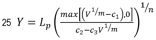


Claims

Priority Applications (6)
| Application Number | Priority Date | Filing Date | Title |
|---|---|---|---|
| MX2017013963A MX368598B (en) | 2015-05-20 | 2016-05-12 | Pixel processing and encoding. |
| AU2016264827A AU2016264827B2 (en) | 2015-05-20 | 2016-05-12 | Pixel processing and encoding |
| US15/503,301 US9918095B1 (en) | 2015-05-20 | 2016-05-12 | Pixel processing and encoding |
| EP16796833.8A EP3298780B1 (en) | 2015-05-20 | 2016-05-12 | Pixel processing and encoding |
| CN201680029093.8A CN107615761B (en) | 2015-05-20 | 2016-05-12 | Methods, devices and computer readable media for pixel processing and encoding |
| JP2017560163A JP6496046B2 (en) | 2015-05-20 | 2016-05-12 | Pixel processing and encoding |
Applications Claiming Priority (2)
| Application Number | Priority Date | Filing Date | Title |
|---|---|---|---|
| US201562164160P | 2015-05-20 | 2015-05-20 | |
| US62/164,160 | 2015-05-20 |
Publications (1)
| Publication Number | Publication Date |
|---|---|
| WO2016186551A1 true WO2016186551A1 (en) | 2016-11-24 |
Family
ID=57320949
Family Applications (1)
| Application Number | Title | Priority Date | Filing Date |
|---|---|---|---|
| PCT/SE2016/050432 WO2016186551A1 (en) | 2015-05-20 | 2016-05-12 | Pixel processing and encoding |
Country Status (7)
| Country | Link |
|---|---|
| US (1) | US9918095B1 (en) |
| EP (1) | EP3298780B1 (en) |
| JP (1) | JP6496046B2 (en) |
| CN (1) | CN107615761B (en) |
| AU (1) | AU2016264827B2 (en) |
| MX (1) | MX368598B (en) |
| WO (1) | WO2016186551A1 (en) |
Cited By (5)
| Publication number | Priority date | Publication date | Assignee | Title |
|---|---|---|---|---|
| EP3185558A1 (en) * | 2015-12-23 | 2017-06-28 | Canon Kabushiki Kaisha | Method, apparatus and system for determining a luma value |
| CN107197235A (en) * | 2017-06-26 | 2017-09-22 | 杭州当虹科技有限公司 | A kind of HDR video pre-filterings method |
| WO2017200447A1 (en) * | 2016-05-16 | 2017-11-23 | Telefonaktiebolaget Lm Ericsson (Publ) | Pixel processing with color component |
| EP3560200A4 (en) * | 2016-12-23 | 2019-11-13 | Telefonaktiebolaget LM Ericsson (publ) | Chroma adjustment with color components in color spaces in video coding |
| WO2020149605A1 (en) * | 2019-01-14 | 2020-07-23 | Samsung Electronics Co., Ltd. | Electronic apparatus and control method thereof |
Families Citing this family (7)
| Publication number | Priority date | Publication date | Assignee | Title |
|---|---|---|---|---|
| KR102412007B1 (en) * | 2017-07-20 | 2022-06-22 | 삼성전자주식회사 | Electronic device and method for compressing high dynamic range image data in the electronic device |
| CN108769804B (en) * | 2018-04-25 | 2020-12-15 | 杭州当虹科技股份有限公司 | Format conversion method for high dynamic range video |
| GB2580173B (en) * | 2018-12-21 | 2022-07-27 | Canon Kk | A filter |
| CN109685859B (en) * | 2018-12-24 | 2021-06-08 | 哈尔滨工业大学(深圳) | Three-dimensional color automatic adjustment method based on 3D lookup table |
| CN111343462B (en) * | 2020-03-08 | 2021-10-22 | 苏州浪潮智能科技有限公司 | Image data compression transmission method, device and storage medium |
| CN112418015B (en) * | 2020-11-09 | 2023-07-28 | 云南电网有限责任公司昆明供电局 | Method and system for checking and modifying fixed value of secondary equipment of power system |
| CN112734654B (en) * | 2020-12-23 | 2024-02-02 | 中国科学院苏州纳米技术与纳米仿生研究所 | Image processing method, device, equipment and storage medium |
Citations (3)
| Publication number | Priority date | Publication date | Assignee | Title |
|---|---|---|---|---|
| US20090123089A1 (en) * | 2007-11-14 | 2009-05-14 | Microsoft Corporation | Adaptive filtering for image transform processes |
| WO2013142067A1 (en) * | 2012-03-21 | 2013-09-26 | Dolby Laboratories Licensing Corporation | Systems and methods for iso-perceptible power reduction for displays |
| US20140078198A1 (en) * | 2012-09-17 | 2014-03-20 | Samsung Electronics Co., Ltd. | Methods and devices for controlling operations of an organic light-emitting diode display |
Family Cites Families (4)
| Publication number | Priority date | Publication date | Assignee | Title |
|---|---|---|---|---|
| JP3723043B2 (en) * | 2000-04-21 | 2005-12-07 | シャープ株式会社 | Image processing apparatus, image reading apparatus, and image forming apparatus |
| JP2005210441A (en) * | 2004-01-23 | 2005-08-04 | Sanyo Electric Co Ltd | Image signal processing apparatus |
| JP5137464B2 (en) * | 2006-06-08 | 2013-02-06 | パナソニック株式会社 | Image processing apparatus, image processing method, image processing program, and integrated circuit |
| AU2015275320A1 (en) * | 2015-12-23 | 2017-07-13 | Canon Kabushiki Kaisha | Method, apparatus and system for determining a luma value |
-
2016
- 2016-05-12 JP JP2017560163A patent/JP6496046B2/en active Active
- 2016-05-12 CN CN201680029093.8A patent/CN107615761B/en active Active
- 2016-05-12 EP EP16796833.8A patent/EP3298780B1/en active Active
- 2016-05-12 WO PCT/SE2016/050432 patent/WO2016186551A1/en active Application Filing
- 2016-05-12 AU AU2016264827A patent/AU2016264827B2/en not_active Ceased
- 2016-05-12 MX MX2017013963A patent/MX368598B/en active IP Right Grant
- 2016-05-12 US US15/503,301 patent/US9918095B1/en active Active
Patent Citations (3)
| Publication number | Priority date | Publication date | Assignee | Title |
|---|---|---|---|---|
| US20090123089A1 (en) * | 2007-11-14 | 2009-05-14 | Microsoft Corporation | Adaptive filtering for image transform processes |
| WO2013142067A1 (en) * | 2012-03-21 | 2013-09-26 | Dolby Laboratories Licensing Corporation | Systems and methods for iso-perceptible power reduction for displays |
| US20140078198A1 (en) * | 2012-09-17 | 2014-03-20 | Samsung Electronics Co., Ltd. | Methods and devices for controlling operations of an organic light-emitting diode display |
Non-Patent Citations (1)
| Title |
|---|
| CHOU C-H; ET AL.: "Colour image compression based on the measure of just noticeable colour difference", IET IMAGE PROCESSING, vol. 2, no. 6, 15 December 2008 (2008-12-15), pages 304 - 322, XP006032162, ISSN: 1751-9667 * |
Cited By (9)
| Publication number | Priority date | Publication date | Assignee | Title |
|---|---|---|---|---|
| EP3185558A1 (en) * | 2015-12-23 | 2017-06-28 | Canon Kabushiki Kaisha | Method, apparatus and system for determining a luma value |
| WO2017200447A1 (en) * | 2016-05-16 | 2017-11-23 | Telefonaktiebolaget Lm Ericsson (Publ) | Pixel processing with color component |
| US10699671B2 (en) | 2016-05-16 | 2020-06-30 | Telefonaktiebolaget Lm Ericsson | Pixel processing with color component |
| EP3560200A4 (en) * | 2016-12-23 | 2019-11-13 | Telefonaktiebolaget LM Ericsson (publ) | Chroma adjustment with color components in color spaces in video coding |
| US11330278B2 (en) | 2016-12-23 | 2022-05-10 | Telefonaktiebolaget Lm Ericsson (Publ) | Chroma adjustment with color components in color spaces in video coding |
| CN107197235A (en) * | 2017-06-26 | 2017-09-22 | 杭州当虹科技有限公司 | A kind of HDR video pre-filterings method |
| CN107197235B (en) * | 2017-06-26 | 2018-10-12 | 杭州当虹科技股份有限公司 | A kind of HDR video pre-filterings method |
| WO2020149605A1 (en) * | 2019-01-14 | 2020-07-23 | Samsung Electronics Co., Ltd. | Electronic apparatus and control method thereof |
| US11336905B2 (en) | 2019-01-14 | 2022-05-17 | Samsung Electronics Co., Ltd. | Storing index information for pixel combinations with similarity to a pixel to replace the pixel information |
Also Published As
| Publication number | Publication date |
|---|---|
| MX2017013963A (en) | 2018-01-16 |
| CN107615761A (en) | 2018-01-19 |
| JP2018524850A (en) | 2018-08-30 |
| EP3298780B1 (en) | 2020-01-01 |
| US9918095B1 (en) | 2018-03-13 |
| AU2016264827B2 (en) | 2019-05-16 |
| EP3298780A4 (en) | 2018-06-06 |
| MX368598B (en) | 2019-10-08 |
| JP6496046B2 (en) | 2019-04-03 |
| EP3298780A1 (en) | 2018-03-28 |
| CN107615761B (en) | 2020-04-07 |
| AU2016264827A1 (en) | 2017-11-23 |
Similar Documents
| Publication | Publication Date | Title |
|---|---|---|
| AU2016264827B2 (en) | Pixel processing and encoding | |
| US11025927B2 (en) | Pixel pre-processing and encoding | |
| JP6516851B2 (en) | Pixel pre-processing and encoding | |
| CN107852513B (en) | Encoding pixels of an input video sequence | |
| JP6651005B2 (en) | Determination of QP value | |
| CN107431818B (en) | Image data processing method | |
| WO2017083784A1 (en) | Adaptive chroma downsampling and color space conversion techniques | |
| EP2406959A1 (en) | Layered compression of high dynamic range, visual dynamic range, and wide color gamut video | |
| CN107925778B (en) | Pixel pre-processing and encoding | |
| US20190364288A1 (en) | Chroma adjustment with color components in color spaces in video coding | |
| WO2018067052A1 (en) | Pre-processing of hdr video involving chroma adjustment | |
| US11259054B2 (en) | In-loop deblocking filter apparatus and method for video coding |
Legal Events
| Date | Code | Title | Description |
|---|---|---|---|
| 121 | Ep: the epo has been informed by wipo that ep was designated in this application |
Ref document number: 16796833 Country of ref document: EP Kind code of ref document: A1 |
|
| WWE | Wipo information: entry into national phase |
Ref document number: 15503301 Country of ref document: US |
|
| WWE | Wipo information: entry into national phase |
Ref document number: MX/A/2017/013963 Country of ref document: MX |
|
| ENP | Entry into the national phase |
Ref document number: 2017560163 Country of ref document: JP Kind code of ref document: A |
|
| NENP | Non-entry into the national phase |
Ref country code: DE |
|
| ENP | Entry into the national phase |
Ref document number: 2016264827 Country of ref document: AU Date of ref document: 20160512 Kind code of ref document: A |