WO2016186377A1 - 프리러닝 펨토초 레이저 기반의 실시간 합성파 결정을 이용한 거리측정 장치 - Google Patents
프리러닝 펨토초 레이저 기반의 실시간 합성파 결정을 이용한 거리측정 장치 Download PDFInfo
- Publication number
- WO2016186377A1 WO2016186377A1 PCT/KR2016/005028 KR2016005028W WO2016186377A1 WO 2016186377 A1 WO2016186377 A1 WO 2016186377A1 KR 2016005028 W KR2016005028 W KR 2016005028W WO 2016186377 A1 WO2016186377 A1 WO 2016186377A1
- Authority
- WO
- WIPO (PCT)
- Prior art keywords
- light
- measurement
- femtosecond laser
- synthesized wave
- distance
- Prior art date
- Legal status (The legal status is an assumption and is not a legal conclusion. Google has not performed a legal analysis and makes no representation as to the accuracy of the status listed.)
- Ceased
Links
Images


Classifications
-
- G—PHYSICS
- G01—MEASURING; TESTING
- G01S—RADIO DIRECTION-FINDING; RADIO NAVIGATION; DETERMINING DISTANCE OR VELOCITY BY USE OF RADIO WAVES; LOCATING OR PRESENCE-DETECTING BY USE OF THE REFLECTION OR RERADIATION OF RADIO WAVES; ANALOGOUS ARRANGEMENTS USING OTHER WAVES
- G01S7/00—Details of systems according to groups G01S13/00, G01S15/00, G01S17/00
- G01S7/48—Details of systems according to groups G01S13/00, G01S15/00, G01S17/00 of systems according to group G01S17/00
- G01S7/483—Details of pulse systems
- G01S7/486—Receivers
-
- G—PHYSICS
- G01—MEASURING; TESTING
- G01S—RADIO DIRECTION-FINDING; RADIO NAVIGATION; DETERMINING DISTANCE OR VELOCITY BY USE OF RADIO WAVES; LOCATING OR PRESENCE-DETECTING BY USE OF THE REFLECTION OR RERADIATION OF RADIO WAVES; ANALOGOUS ARRANGEMENTS USING OTHER WAVES
- G01S17/00—Systems using the reflection or reradiation of electromagnetic waves other than radio waves, e.g. lidar systems
- G01S17/02—Systems using the reflection of electromagnetic waves other than radio waves
- G01S17/06—Systems determining position data of a target
- G01S17/08—Systems determining position data of a target for measuring distance only
- G01S17/32—Systems determining position data of a target for measuring distance only using transmission of continuous waves, whether amplitude-, frequency-, or phase-modulated, or unmodulated
- G01S17/36—Systems determining position data of a target for measuring distance only using transmission of continuous waves, whether amplitude-, frequency-, or phase-modulated, or unmodulated with phase comparison between the received signal and the contemporaneously transmitted signal
-
- G—PHYSICS
- G01—MEASURING; TESTING
- G01S—RADIO DIRECTION-FINDING; RADIO NAVIGATION; DETERMINING DISTANCE OR VELOCITY BY USE OF RADIO WAVES; LOCATING OR PRESENCE-DETECTING BY USE OF THE REFLECTION OR RERADIATION OF RADIO WAVES; ANALOGOUS ARRANGEMENTS USING OTHER WAVES
- G01S7/00—Details of systems according to groups G01S13/00, G01S15/00, G01S17/00
- G01S7/48—Details of systems according to groups G01S13/00, G01S15/00, G01S17/00 of systems according to group G01S17/00
- G01S7/491—Details of non-pulse systems
Definitions
- the present invention relates to a distance measuring apparatus using a real-time synthesized wave crystal based on a free running femtosecond laser.
- the configuration is simple by measuring the wavelength and phase of a synthesized wave generated by interference between frequency modes in a free running femtosecond laser.
- the present invention relates to a distance measuring device using a free-running femtosecond laser-based real-time synthesized wave crystal capable of measuring distance with high resolution.
- the present invention relates to a femtosecond laser synthetic wavelength interferometer which generates a long wavelength synthesized wave of a radio wave band from interference between numerous modes of a femtosecond laser and uses the distance to measure it.
- the synthesized waves having a specific wavelength suitable for the measurement distance are selected.
- the desired distance can be measured by comparing the progress of the reference arm and the measurement arm.
- the wavelength of the selected synthesized waves does not change with time. Since the wavelength of the selected synthesized waves depends on the interval between frequency modes determined by the optical path length of the femtosecond laser resonator, a technique for keeping the optical path length of the resonator constant is required.
- the interval between frequency modes is the repetition rate at which the laser pulse is generated ( Same as), and the repetition rate ( )silver (Round) or It can be represented as (linear).
- Is the luminous flux inside the resonator Is the length of the femtosecond laser resonator.
- Length of resonator due to changes in temperature and environment When the change is made, the repetition rate of the femtosecond laser is also changed. In this case, the repetition rate of the femtosecond laser can be stabilized by controlling the length of the laser resonator so that the laser pulse can be phase locked to the atomic clock.
- the conventional femtosecond laser uses a femtosecond laser with a stable repetition rate in a distance measuring method using a femtosecond laser.
- complex devices such as piezoelectric elements, voltage amplifiers, function generators, and phase locked loop circuits are required.
- the driving range of the piezoelectric element is limited to a level within 10 ⁇ m, it is possible to stabilize the repetition rate when the temperature change of the surrounding environment occurs several degrees or more. It can be out of control and, in more severe cases, even the generation of femtosecond laser pulses becomes impossible. In this case, the conventional distance measuring method using femtosecond lasers can no longer be used.
- Korean Patent Publication No. 1448831 is a device for measuring distance using a femtosecond laser-based synthesized wave interferometer, and discloses a distance measuring technique using a femtosecond laser-based phase locked synthesized wave interferometer and eliminates nonlinear errors according to phases. have.
- the present invention measures the wavelength and phase of a synthesized wave generated by interference between frequency modes in a free running femtosecond laser in real time, thereby realizing a free-running femtosecond laser-based real-time synthesized wave capable of measuring distance with high resolution.
- An object of the present invention is to provide a distance measuring device using crystals.
- a distance measuring apparatus using a real-time synthesized wave crystal based on a free running femtosecond laser comprising: a free running femtosecond laser light source for emitting laser light; A light splitter configured to split the laser light into reference light and measurement light reflected from a measurement target; A reference photodetector for detecting the reference light; A measurement photodetector for detecting the measurement light; A frequency measuring unit measuring the repetition rate of the laser light, determining a degree of the synthesized wave to be extracted, and outputting the repetition rate and the order; A phase measuring unit configured to mix the detected reference light and the measured light with a high frequency signal, respectively, and pass the mixed reference light and the mixed measurement light through a low pass filter to measure a phase difference between the extracted reference synthesized wave and the measured synthesized wave; And a distance calculator configured to calculate distance information between the optical splitter and the measurement target using the repetition rate, the phase difference, and the order of the synthesized wave
- the measurement target may be a mirror.
- a distance measuring apparatus using a real-time synthesized wave crystal based on a free running femtosecond laser, Free running femtosecond laser light source for emitting a laser light A multi-channel light splitter configured to split the laser light into two or more measurement beams incident to the reference light and to different measurement targets; A reference photodetector for detecting the reference light; A multi-channel photodetector comprising one or more measurement photodetectors each having one-to-one correspondence with the measurement lights and detecting the measurement light; A frequency measuring unit measuring the repetition rate of the laser light, determining a degree of the synthesized wave to be extracted, and outputting the repetition rate and the order; A multi-channel phase measuring unit for mixing the detected reference light and measurement light with the high frequency signal, respectively, and passing the mixed reference light and the mixed measurement light through a low pass filter to measure phase differences between the extracted reference synthesized waves and the respective measured synthesized waves.
- the free-running femtosecond laser light source may be an erbium fiber femtosecond laser having a center wavelength of 1550 nm, a bandwidth of 50 nm, and a pulse width of 100 fs.
- the free running femtosecond laser light source may be an ytterbium fiber femtosecond laser having a center wavelength of 1030 nm, a bandwidth of 50 nm, and a pulse width of 50 fs.
- the free running femtosecond laser light source may be a titanium: sapphire femtosecond laser having a center wavelength of 800 nm, a bandwidth of 100 nm, and a pulse width of 10 fs.
- the present invention measures the wavelength and phase of a synthesized wave generated by interference between frequency modes in a free-running femtosecond laser in real time, so that the configuration is simple and high-resolution femtosecond laser-based distance can be measured. It is possible to provide a distance measuring device using a real-time synthesized wave determination.
- FIG. 1 is a block diagram of a distance measuring apparatus using real-time synthesized wave determination based on free running femtosecond laser according to an embodiment of the present invention.
- FIG. 2 is a block diagram of a case in which a mirror is omitted in a distance measuring device using real-time synthesized wave determination based on free running femtosecond laser according to an embodiment of the present invention.
- FIG. 3 is a block diagram of a case in which an optocoupler is added in a distance measuring apparatus using real-time synthesized wave determination based on free running femtosecond laser according to an embodiment of the present invention.
- Applicant has contemplated how to improve the economics and performance by simplifying the device to stabilize the femtosecond laser when measuring the distance by using the composite wave of the femtosecond laser, free running without stabilizing the repetition rate instead of the conventional femtosecond laser
- the present invention has been completed by using a femtosecond laser and adding a device for measuring the frequency of a free running femtosecond laser.
- a distance measuring apparatus using real-time synthesized wave determination based on free running femtosecond laser may include a free running femtosecond laser light source 110, a light splitter 120, and a reference photodetector 130. ), A measurement photodetector 150, a measurement target 140, a frequency measuring unit 220, a phase measuring unit 230, a distance calculator 300, and a reference clock 210.
- the free running femtosecond laser light source 110 is a laser light source used for distance measurement, and may be a laser that generates a laser pulse having a pulse width of femtosecond level and does not control the repetition rate at which the pulse is generated.
- the free running femtosecond laser light source 110 is an optical fiber femtosecond laser having a center wavelength of 1550 nm, a bandwidth of 60 nm, and a pulse width of 150 fs, or a titanium: sapphire femtosecond laser having a center wavelength of 800 nm, a bandwidth of 100 nm, and a pulse width of 100 fs. Can be.
- the optical splitter 120 is a device for splitting laser light into space, and includes a beam splitter, diffraction optics, a beam diffuser, a beam expander, and a fiber coupler. ) May be implemented.
- the reference photodetector 130 may detect a portion of the laser light at the reference point and transmit the detected signal to the phase measurement unit 230 using a wired or wireless communication technology.
- the detected signal may be an electrical signal.
- the measurement target 140 is an object placed at a position for distance measurement, and preferably, a mirror or the like capable of reflecting laser light may be selected.
- the distance calculator 300 may calculate distance information between the light splitter 120 and the measurement target by using the measured repetition rate, the phase difference, and the order of the synthesized wave.
- the reference clock 210 is an atomic clock used to provide a clock to the frequency measuring unit 220 and the phase measuring unit 230.
- the reference clock 210 has a frequency of 10 MHz and may be used to increase the accuracy and long-term stability of the distance measurement. . Since the free running femtosecond laser light source 110 is not stabilized in the atomic clock by using a resonator, even if a reference clock is not provided, distance measurement using a real-time synthesized wave crystal based on a free running femtosecond laser according to an embodiment of the present invention. The device may operate.
- the laser light is emitted from the free running femtosecond laser light source 110, and the laser light emitted from the free running femtosecond laser light source 110 is reflected by the light splitter 120 from the reference light and the measurement target (that is, the measurement light). Measurement light which is directed to and reflected from the measurement target).
- the signals detected by the detectors may be input to the phase measuring unit 230.
- the distance calculator 300 may calculate distance information between the optical splitter 120 and the measurement target from the repetition rate, the phase difference, and the order of the synthesized wave.
- the distance calculation unit 300 calculates the distance information as follows: This can be used.
- the length corresponding to the integral multiple of the wavelength of the synthesized wave must be determined. In other words, it is determined how many synthesized wavelengths are needed to be closest to the distance to be measured, You must decide. remind The determination of the value can be determined by measuring twice with different repetition rates of the laser.
- the wavelength of the initial synthesized wave ( Using) Next, change the repetition rate of the femtosecond laser and measure the wavelength of the synthesized wave Once again away After measuring and Alliance distance Wow Can be determined.
- the limit of the maximum measurement distance at which the distance value can be determined as one is May appear. That is, the amount of change in repetition rate
- the distance can be determined with a unique value within 1.5 km at 100 kHz, 15 km at 10 kHz, and 150 km at 1 kHz.
- the maximum measurement distance, which can determine the distance measurement value is complementary to the measurement accuracy. In the actual experiment, the distance was determined as the only value within 1.35km when the measurement precision was 42 ⁇ m.
- the distance can be measured without ambiguity, and the higher-order synthesized waves can be measured with higher resolution. By using both low-order and high-order synthesized waves simultaneously, longer distances can be measured with higher resolution.
- the auxiliary measuring means may be a conventional distance measuring tool such as a tape measure.
- the auxiliary measuring means that can be used up to 1.5 m should be able to produce measurements of less than 1.5 m error, which may be sufficient as a commonly used tape measure.
- FIG. 2 is a block diagram of a case in which a mirror is omitted in a distance measuring device using real-time synthesized wave determination based on free running femtosecond laser according to an embodiment of the present invention. Comparing FIG. 1 and FIG. 2, it can be seen that the mirror positioned at the measurement target is omitted and replaced by the photodetector 150 for measurement.
- the laser light is emitted from the free running femtosecond laser light source 110, and the laser light emitted from the free running femtosecond laser light source 110 is incident to the reference photodetector 130 by the light splitter 120. It is separated into the measurement light incident on the measuring photodetector 150. After the reference light is incident on the reference photodetector 130 and the measurement light is incident on the measurement photodetector 150, signals detected by the photodetectors are input to the phase measuring unit 230.
- the phase measuring unit 230 mixes the detected reference light and the measurement light with the high frequency signal, respectively, and passes the mixed reference light and the mixed measurement light through the low pass filter to extract the reference synthesized wave and the measured synthesized wave, respectively.
- the phase measurer 230 measures a phase difference between the synthesized reference light (ie, the reference synthesized wave) and the synthesized measurement light (ie, the measured synthesized wave), and the frequency measurer 220 measures the free running femtosecond laser in real time. While measuring the repetition rate, determine the order of the synthesized wave to be extracted.
- the phase measurer 230 inputs the phase difference to the distance calculator 300
- the frequency measurer 220 inputs the repetition rate and the order of the summation wave to the distance calculator 300.
- the distance calculator 300 may calculate distance information between the optical splitter 120 and the measurement target from the repetition rate, the phase difference, and the order of the synthesized wave.
- the distance calculation unit 300 calculates the distance information as follows: This can be used.
- Is distance information determined by the difference in the optical path between the reference photodetector 130 and the measurement photodetector 150, Is a free running femtosecond laser Wavelength of difference wave, silver An integer value that, when multiplied by, produces the largest value that does not exceed the distance information, Is selected Synthesized Wave of Differential Reference Light and Selected Phase difference of the synthesized wave of the difference measurement light, Is the speed of light in the atmosphere ( speed of light in vacuum / refractive index of air), Is the repetition rate of the free running femtosecond laser.
- Equation used in calculating distance information Except that, in the embodiment shown in FIG. The determination and the overall operation of the distance measuring apparatus corresponds to that described above with reference to FIG.
- FIG. 3 is a block diagram when an optical coupler 160 is added to a distance measuring apparatus using real-time synthesized wave determination based on free running femtosecond laser according to an embodiment of the present invention. Comparing FIG. 1 and FIG. 3, it can be seen that the optocoupler 160 is disposed between the free running femtosecond laser light source 110 and the light splitter 120.
- the arrangement of the optical coupler 160 is to prevent an error caused by mixing the reference light and the measurement light by preventing the reference light and the measurement light from mixing with each other.
- the optical coupler 160 is added in the distance measuring device using the free-running femtosecond laser-based real-time synthesized wave determination according to the embodiment of FIG. 3, the equations used in calculating distance information and synthesis Order of the wave and Determination and the overall operation of the distance measuring device is the same as the embodiment described above with reference to Figure 1, so a detailed description thereof will be omitted.
- the operation principle of the distance measuring device shown in FIG. 4 is the same as that of the distance measuring device shown in FIG. 2, it may be sufficient to extend the above description of the distance measuring device shown in FIG. 2 to a plurality of measurement targets.
- the multi-channel splitter 121 and Distance information of the first measurement target ( ) In the multi-channel phase measurement unit 231 The phase difference between the synthesized wave of the reference light and the synthesized wave of the measured light ), Such as Subscripts may be added to indicate that the variable is related to the first measurement target.
Landscapes
- Engineering & Computer Science (AREA)
- Physics & Mathematics (AREA)
- Computer Networks & Wireless Communication (AREA)
- General Physics & Mathematics (AREA)
- Radar, Positioning & Navigation (AREA)
- Remote Sensing (AREA)
- Electromagnetism (AREA)
- Optical Radar Systems And Details Thereof (AREA)
Abstract
본 발명은 프리러닝하는 펨토초 레이저에서 주파수 모드간의 간섭으로 생성된 긴 파장의 합성파의 파장과 위상을 실시간으로 측정함으로써 고분해능으로 긴 거리를 측정하는 프리러닝 펨토초 레이저 기반의 실시간 합성파 결정을 이용한 거리측정 장치에 관한 것이다. 본 발명에 따른 거리측정 장치에서, 프리러닝 펨토초 레이저 광원은 레이저 광을 방사하고, 광분할기는 프리러닝 펨토초 레이저 광원으로부터 방사되는 레이저 광을 기준광과 측정표적으로부터 반사되는 측정광으로 분리하며, 기준용 광검출기와 측정용 광검출기는 기준광과 측정광을 각각 검출하여 전기적 신호로 변환한다. 그리고 주파수 측정부는 프리러닝 펨토초 레이저의 반복률을 측정함과 동시에 추출하고자 하는 합성파의 차수를 결정하고, 위상 측정부는 검출된 기준광 및 측정광을 상기 고주파 신호와 각각 합성하여 합성된 기준광과 합성된 측정광 간의 위상차를 측정하고, 거리 산출부는 반복률, 합성파의 차수 및 위상차을 이용하여 상기 광분할기와 상기 측정표적간의 거리정보를 산출한다.
Description
본 발명은 프리러닝 펨토초 레이저 기반의 실시간 합성파 결정을 이용한 거리측정 장치에 관한 것으로, 프리러닝하는 펨토초 레이저에서 주파수 모드간의 간섭으로 생성된 합성파의 파장과 위상을 실시간으로 측정함으로써, 구성이 단순하면서도 고분해능으로 거리를 측정할 수 있는 프리러닝 펨토초 레이저 기반의 실시간 합성파 결정을 이용한 거리측정 장치에 관한 것이다.
본 발명은 펨토초 레이저의 수많은 모드간의 간섭으로부터 라디오파 대역의 긴 파장의 합성파를 생성하고, 이를 이용해서 거리를 측정하는 펨토초 레이저 합성파 간섭계(synthetic wavelength interferometer)와 관련된다.
일반적으로 펨토초 레이저 합성파 간섭계는 주파수 모드간의 간섭에 의하여 파장이 서로 다른 합성파들이 펨토초 레이저에서 생성되면, 이 가운데 측정거리에 적합한 특정한 파장의 합성파들을 선택하여, 선택된 합성파들이 간섭계의 기준팔(reference arm)과 측정팔(measurement arm)에서의 진행하는 과정을 비교하여 원하는 거리를 측정할 수 있다.
종래의 펨토초 레이저를 이용한 거리측정 방법에서는 선택된 합성파들의 파장이 시간에 따라 변화하지 않는 것으로 가정하였다. 그리고 선택된 합성파들의 파장은 펨토초 레이저 공진기의 광경로 길이에 의해서 결정되는 주파수 모드간 간격에 의존하기 때문에, 공진기의 광경로 길이를 일정하게 유지시키기 위한 기술이 필요하였다.
구체적으로 공진기의 길이와 주파수 모드간 간격의 관계에 대해서 설명하면, 주파수 모드간의 간격은 레이저 펄스가 생성되는 반복률( )과 동일하고, 공진기의 구조에 따라 반복률(
 )은
)은  (원형) 또는
 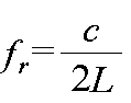 (선형)로 나타낼 수 있다. 여기서,
  는 공진기 내부에서의 광속이고,
  은 펨토초 레이저 공진기의 길이이다. 온도 및 환경의 변화로 인해서 공진기의 길이
  이 변하게 되면, 펨토초 레이저의 반복률도 함께 변화하게 되는데, 이 경우 레이저 펄스가 원자시계에 위상 잠금될 수 있도록 레이저 공진기의 길이를 제어함으로써, 펨토초 레이저의 반복률을 안정화할 수 있다.
상기와 같은 원리를 통해서 펨토초 레이저 반복률의 주파수 안정도를 높일 수 있으므로, 종래의 펨토초 레이저를 이용한 거리측정 방법에서는 반복률이 안정화된 펨토초 레이저를 사용하고 있다. 다만, 반복률을 안정화시키기 위해서는, 공진기의 길이를 미세하게 제어할 수 있어야 하므로, 압전소자, 전압증폭기, 함수 발생기, 위상동기루프(phase locked loop)회로 등과 같은 복잡한 장치들이 필요하였다.
그런데 상기의 장치들을 이용함으로써 높은 수준으로 반복률을 안정화하는 것이 가능하더라도, 압전소자의 구동범위가 10μm 이내의 수준으로 제한되기 때문에, 주변 환경의 온도변화가 수 ℃ 이상 발생할 때는 반복률을 안정화할 수 있는 제어범위를 벗어나게 되며, 더 심한 경우에는 펨토초 레이저 펄스의 생성조차도 불가능해지는 상황이 발생할 수 있다. 이와 같은 경우에는 종래의 펨토초 레이저를 이용한 거리측정 방법은 더 이상 사용이 불가능하게 된다.
뿐만 아니라, 종래의 펨토초 레이저 합성파를 이용한 거리 측정 방법의 경우에는 전자기기나 광학기기에서 발생하는 누화(cross talk)에 의해 수 mm 이상의 주기적인 오차(cyclic error)도 발생한다.
따라서, 펨토초 레이저 공진기의 길이 조절에 대한 한계를 극복하고, 전자기기나 광학기기의 누화에 따라 발생하는 주기적인 오차를 줄이기 위한 거리측정 방법이 필요하다.
한국등록특허공보 제1448831호는 펨토초 레이저 기반의 합성파 간섭계를 이용하여 거리를 측정하는 장치로서, 펨토초 레이저 기반의 위상 잠금 합성파 간섭계를 이용하면서도 위상에 따른 비선형오차를 제거한 거리측정 기술을 개시하고 있다.
다만, 펨토초 레이저 공진기의 길이 조절에 대한 한계는 극복하지 못하였다.
이에 본 발명은 프리러닝하는 펨토초 레이저에서 주파수 모드간의 간섭으로 생성된 합성파의 파장과 위상을 실시간으로 측정함으로써, 구성이 단순하면서도 고분해능으로 거리를 측정할 수 있는 프리러닝 펨토초 레이저 기반의 실시간 합성파 결정을 이용한 거리측정 장치를 제공하는 것을 목적으로 한다.
본 발명의 다른 목적들은 이하의 실시예에 대한 설명을 통해 쉽게 이해될 수 있을 것이다.
상기한 바와 같은 목적을 달성하기 위한 본 발명의 바람직한 일 실시예에 따른 프리러닝 펨토초 레이저 기반의 실시간 합성파 결정을 이용한 거리측정 장치는, 레이저 광을 방사하는 프리러닝 펨토초 레이저 광원; 상기 레이저 광이 입사되며, 상기 레이저 광을 기준광과 측정표적으로부터 반사되는 측정광으로 분리하는 광분할기; 상기 기준광을 검출하는 기준용 광검출기; 상기 측정광을 검출하는 측정용 광검출기; 상기 레이저 광의 반복률을 측정하고, 추출하고자 하는 합성파의 차수를 결정하여, 상기 반복률과 상기 차수를 출력하는 주파수 측정부; 검출된 기준광 및 측정광을 고주파 신호와 각각 혼합하고, 혼합된 기준광 및 혼합된 측정광을 각각 저주파 통과 여과기에 통과시켜 추출된 기준 합성파와 측정 합성파의 위상차를 측정하는 위상 측정부; 상기 반복률, 상기 위상차 및 상기 합성파의 차수를 이용하여 상기 광분할기와 상기 측정표적간의 거리정보를 산출하는 거리 산출부;를 포함하고, 상기 고주파 신호는 상기 반복률과 상기 합성파의 차수에 근거하여 결정될 수 있다.
또한, 상기 거리정보는 다음 수학식,

여기서,  : 상기 거리정보,


또한, 상기 측정표적은 거울일 수 있다.
상기한 바와 같은 목적을 달성하기 위한 본 발명의 바람직한 다른 실시예에 따른 프리러닝 펨토초 레이저 기반의 실시간 합성파 결정을 이용한 거리측정 장치는, 레이저 광을 방사하는 프리러닝 펨토초 레이저 광원; 상기 레이저 광이 입사되며, 상기 레이저 광을 기준광과 측정표적에 입사되는 측정광으로 분리하는 광분할기; 상기 기준광을 검출하는 기준용 광검출기; 상기 측정광을 검출하는 측정용 광검출기; 상기 레이저 광의 반복률을 측정하고, 추출하고자 하는 합성파의 차수를 결정하여, 상기 반복률과 상기 차수를 출력하는 주파수 측정부; 검출된 기준광 및 측정광을 고주파 신호와 각각 혼합하고, 혼합된 기준광 및 혼합된 측정광을 각각 저주파 통과 여과기에 통과시켜 추출된 기준 합성파와 측정 합성파의 위상차를 측정하는 위상 측정부; 및 상기 반복률, 상기 위상차 및 상기 합성파의 차수를 이용하여 상기 광분할기와 상기 측정표적간의 거리정보를 산출하는 거리 산출부;를 포함하고, 상기 고주파 신호는 상기 반복률과 상기 합성파의 차수에 근거하여 결정될 수 있다.
또한, 상기 거리정보는 다음 수학식,

여기서,  : 상기 거리정보,


상기한 바와 같은 목적을 달성하기 위한 본 발명의 바람직한 또 다른 실시예에 따른 프리러닝 펨토초 레이저 기반의 실시간 합성파 결정을 이용한 거리측정 장치는, 레이저 광을 방사하는 프리러닝 펨토초 레이저 광원; 상기 레이저 광이 입사되며, 상기 레이저 광을 기준광과 서로 다른 측정표적들에 입사되는 둘 이상의 측정광들로 분리하는 다채널광분할기; 상기 기준광을 검출하는 기준용 광검출기; 상기 측정광들과 일대일 대응이 되어, 상기 측정광을 각각 검출하는 둘 이상의 측정용 광검출기들로 구성된 다채널 측정용 광검출기; 상기 레이저 광의 반복률을 측정하고, 추출하고자 하는 합성파의 차수를 결정하여, 상기 반복률과 상기 차수를 출력하는 주파수 측정부; 검출된 기준광 및 측정광들을 고주파 신호와 각각 혼합하고, 혼합된 기준광 및 혼합된 측정광들을 저주파 통과 여과기에 통과시켜 추출된 기준 합성파들과 각각의 측정 합성파들의 위상차들을 측정하는 다채널위상 측정부; 상기 반복률, 상기 위상차들 및 상기 합성파의 차수를 이용하여, 상기 광분할기와 각각의 상기 위상차와 관련된 측정광이 입사한 측정표적들간의 각각의 거리정보들을 산출하는 거리 산출부;를 포함하고 상기 고주파 신호는 상기 반복률과 상기 합성파의 차수에 근거하여 결정될 수 있다.
또한, 상기 거리정보들은 다음 수학식,

여기서,  : 상기 거리정보,


또한, 상기 프리러닝 펨토초 레이저 광원은 1550nm의 중심 파장, 50nm의 대역폭, 100fs의 펄스폭을 가지는 어븀 광섬유 펨토초 레이저일 수 있다.
또한, 상기 프리러닝 펨토초 레이저 광원은 1030nm의 중심 파장, 50nm의 대역폭, 50fs의 펄스폭을 가지는 이터븀 광섬유 펨토초 레이저일 수 있다.
또한, 상기 프리러닝 펨토초 레이저 광원은 800nm의 중심 파장, 100nm의 대역폭, 10fs의 펄스폭을 가지는 티타늄:사파이어 펨토초 레이저일 수 있다.
이상에서 살펴본 바와 같이 본 발명은 프리러닝하는 펨토초 레이저에서 주파수 모드간의 간섭으로 생성된 합성파의 파장과 위상을 실시간으로 측정함으로써, 구성이 단순하면서도 고분해능으로 거리를 측정할 수 있는 프리러닝 펨토초 레이저 기반의 실시간 합성파 결정을 이용한 거리측정 장치를 제공할 수 있다.
또한, 펨토초 레이저 공진기의 길이 조절의 한계를 극복하고, 전자기기나 광학기기에 의한 주기적인 오차를 줄일 수 있다.
뿐만 아니라, 한 대의 레이저만을 가지고 여러 지점의 거리를 동시에 측정 할 수 있는 기능을 손쉽게 제공할 수 있다.
도 1은 본 발명의 실시예에 따른 프리러닝 펨토초 레이저 기반의 실시간 합성파 결정을 이용한 거리측정 장치의 블록도이다.
도 2는 본 발명의 실시예에 따른 프리러닝 펨토초 레이저 기반의 실시간 합성파 결정을 이용한 거리측정 장치에서 거울이 생략된 경우의 블록도이다.
도 3은 본 발명의 실시예에 따른 프리러닝 펨토초 레이저 기반의 실시간 합성파 결정을 이용한 거리측정 장치에서 광커플러가 추가된 경우의 블록도이다.
도 4는 본 발명의 실시예에 따른 프리러닝 펨토초 레이저 기반의 실시간 합성파 결정을 이용한 거리측정 장치를 이용하여 여러 지점에서 거리를 측정하는 경우에 대한 개요도이다.
본 발명은 다양한 변경을 가할 수 있고 여러 가지 실시예를 가질 수 있는 바, 특정 실시예들을 도면에 예시하고 상세한 설명에 상세하게 설명하고자 한다. 그러나 이는 본 발명을 특정한 실시 형태로 한정하려는 것이 아니며, 본 발명의 사상 및 기술 범위에 포함되는 모든 변경, 균등물 내지 대체물을 포함하는 것으로 이해되어야 한다.
단수의 표현은 문맥상 명백하게 다르게 뜻하지 않는 한, 복수의 표현을 포함한다. 본 출원에서, "포함하다" 또는 "가지다" 등의 용어는 명세서상에 기재된 특징, 숫자, 단계, 동작, 구성요소, 부품 또는 이들을 조합한 것이 존재함을 지정하려는 것이지, 하나 또는 그 이상의 다른 특징들이나 숫자, 단계, 동작, 구성요소, 부품 또는 이들을 조합한 것들의 존재 또는 부가 가능성을 미리 배제하지 않는 것으로 이해되어야 한다.
다르게 정의되지 않는 한, 기술적이거나 과학적인 용어를 포함해서 여기서 사용되는 모든 용어들은 본 발명이 속하는 기술 분야에서 통상의 지식을 가진 자에 의해 일반적으로 이해되는 것과 동일한 의미를 가지고 있다.
본 출원인은 펨토초레이저의 합성파를 이용하여 거리를 측정할 때, 펨토초레이저를 안정화시키는 장치를 간소화하여 경제성 및 성능을 제고하는 방법을 고민한 결과, 기존의 펨토초레이저 대신 반복률을 안정화 하지 않는 프리러닝 펨토초 레이저를 사용하고, 프리러닝 펨토초 레이저의 주파수를 측정하는 장치를 추가하여 본 발명을 완성하기에 이르렀다.
이하에서 첨부된 도면을 참조하여 본 발명의 프리러닝 펨토초 레이저 기반의 실시간 합성파 결정을 이용한 거리측정 장치를 상세히 설명한다.
도 1은 본 발명의 실시예에 따른 프리러닝 펨토초 레이저 기반의 실시간 합성파 결정을 이용한 거리측정 장치의 블록도이다. 도 1을 참조하면 본 발명의 일 실시예에 따른 프리러닝 펨토초 레이저 기반의 실시간 합성파 결정을 이용한 거리측정 장치는 프리러닝 펨토초 레이저 광원(110), 광분할기(120), 기준용 광검출기(130), 측정용 광검출기(150), 측정표적(140), 주파수 측정부(220), 위상 측정부(230), 거리 산출부(300) 및 기준시계(210)를 포함하여 구성될 수 있다.
프리러닝 펨토초 레이저 광원(110)은 거리측정을 위해서 사용되는 레이저 광원으로, 펨토초 수준의 펄스폭을 가지는 레이저 펄스를 생성하며 펄스가 생성되는 반복률을 제어하지 않은 레이저일 수 있다. 상기 프리러닝 펨토초 레이저 광원(110)은 1550nm의 중심 파장, 60nm의 대역폭, 150fs의 펄스폭을 가지는 광섬유 펨토초 레이저이거나 800nm의 중심 파장, 100nm의 대역폭, 100fs의 펄스폭을 가지는 티타늄:사파이어 펨토초 레이저일 수 있다.
광분할기(120)는 레이저 광을 공간상으로 분할하는 장치로서 빔스플리터(beam splitter), 회절광학소자(diffraction optics), 빔 확산기(beam diffuser), 빔확장기(beam expander), 광섬유 커플러(fiber coupler) 등을 이용하여 구현될 수 있다.
기준용 광검출기(130)는 기준지점에서 레이저 광의 일부를 검출하고, 검출된 신호를 유선 또는 무선통신 기술을 이용하여 위상 측정부(230)로 전송할 수 있다. 여기서 상기 검출된 신호는 전기적인 신호일 수 있다.
측정용 광검출기(150)는 측정지점에서 레이저 광의 일부를 검출하고, 검출된 신호를 유선 또는 무선통신 기술을 이용하여 위상 측정부(230)로 전송할 수 있다. 여기서 상기 검출된 신호는 전기적인 신호일 수 있다.
측정표적(140)은 거리측정을 위한 위치에 놓여지는 물체로서, 바람직하게는 레이저 광을 반사할 수 있는 거울 등이 선택될 수 있다.
주파수 측정부(220)는 레이저 광으로부터 프리러닝 펨토초 레이저의 반복률을 측정하고, 추출하고자 하는 합성파의 차수를 결정할 수 있다. 상기 반복률과 상기 합성파의 차수의 곱은 실제로 거리측정을 위해서 사용되는 합성파의 주파수가 되고, 합성파의 주파수에 의해서 합성파의 파장도 계산될 수 있다.
위상 측정부(230)는 검출된 기준광 및 측정광을 고주파 신호와 각각 혼합하고, 저주파 통과 여과기에 통과시켜 각각 기준 합성파 및 측정 합성파를 추출하고, 상기 기준 합성파와 상기 측정 합성파의 위상차를 측정할 수 있다. 상기 고주파 신호는 상기 반복률과 상기 합성파의 차수의 곱에 근접한 것으로, 바람직하게는 상기 고주파 신호의 주파수와 상기 곱의 차이가 저주파 통과 여과기의 통과 대역의 범위보다 작은 것이 바람직하다.
거리 산출부(300)는 측정된 상기 반복률, 상기 위상차 및 상기 합성파의 차수를 이용하여 상기 광분할기(120)와 상기 측정표적간의 거리정보를 산출할 수 있다.
기준시계(210)는 주파수 측정부(220)와 위상 측정부(230)에 클럭을 제공하기 위해서 사용되는 원자시계로서, 10MHz의 진동수를 가지며, 거리측정의 정확도 및 장기 안정도를 높이기 위해 사용될 수 있다. 상기 프리러닝 펨토초 레이저 광원(110)의 경우, 공진기를 이용하여 원자시계에 안정화시키지는 않으므로, 기준시계가 구비되지 않더라도 본 발명의 실시예에 따른 프리러닝 펨토초 레이저 기반의 실시간 합성파 결정을 이용한 거리측정 장치는 동작할 수 있다.
상기 본 발명의 실시예에 따른 프리러닝 펨토초 레이저 기반의 실시간 합성파 결정을 이용한 거리측정 장치의 동작은 다음과 같다.
먼저 프리러닝 펨토초 레이저 광원(110)에서 레이저 광을 방사하고, 상기 프리러닝 펨토초 레이저 광원(110)으로부터 방사되는 레이저 광은 광분할기(120)에 의해 기준광 및 측정표적으로부터 반사되는 측정광(즉, 측정표적을 향하고 이로부터 반사되는 측정광)으로 분리된다. 다음으로 기준용 광검출기(130)에 기준광이 입사되고, 측정용 광검출기(150)에 측정광이 입사된 후에, 상기 검출기들에서 검출된 신호들은 위상 측정부(230)에 입력될 수 있다.
그 다음으로 위상 측정부(230)는 입력된 상기 검출된 신호들로부터 합성된 기준광(즉, 기준 합성파)과 합성된 측정광(즉, 측정 합성파) 간의 위상차를 측정하고, 주파수 측정부(220)는 실시간으로 프리러닝 펨토초 레이저의 반복률을 측정하면서 추출하고자 하는 합성파의 차수  을 결정한다. 그 후, 위상 측정부(230)는 상기 위상차를 거리 산출부(300)에 입력하고, 주파수 측정부(220)는 상기 반복률 및 상기 합상파의 차수를 거리 산출부(300)에 입력할 수 있다. 여기서, 합성파의 차수
  은 최대 측정 거리의 한계와 측정 정밀도를 고려하여 결정될 수 있으며, 측정 정밀도는
  차 합성파 파장의 길이와 위상 측정부(230)의 분해능에 의해 결정된다. 일반적으로 상용 위상 측정기를 통해 얻을 수 있는 위상 측정 분해능은 0.01°(=1/36000) 수준이다. 이를 고려하여, 펄스 반복률
  이 100MHz 인 경우, 10μm 수준의 측정 정밀도를 얻기 위해서는 4차 이상의 합성파가 필요하였다.
최종적으로 거리 산출부(300)는 상기 반복률, 상기 위상차 및 상기 합성파의 차수로부터 광분할기(120)와 측정표적간의 거리정보를 산출할 수 있다.
이 때, 거리 산출부(300)가 거리정보를 산출함에 있어서 다음과 같은 수학식  이 사용될 수 있다.
여기서,  는 기준용 광검출기(130)와 측정용 광검출기(150)의 광경로 차로 결정되는 거리정보이며,
  는 프리러닝 펨토초 레이저의
  차 합성파의 파장,
  은
은  에 곱해졌을 때 거리정보의 값을 넘지 않는 가장 큰 값을 생성하는 정수값,
  은 선택된
은 선택된  차 기준광의 합성파와 선택된
  차 측정광의 합성파의 위상차,
  는 대기 중 빛의 속도(= 진공 중의 빛의 속도/대기의 굴절률),
  은 프리러닝 펨토초 레이저의 반복률이다. 여기서, 상기 위상차는 측정광이 기준광보다 광분할기(120)와 측정표적간의 거리를 왕복하여 더 진행하였기 때문에 발생한 것일 수 있다.
거리 산출부(300)에 제공되지 않은  을 결정하는 방법에 대해서 이하에서 자세히 설명하고자 한다.
합성파의 파장보다 긴 거리를 측정하는 경우에는 측정되는 위상이 2π마다 반복되어 나타나기 때문에, 합성파 파장의 정수배에 해당하는 길이를 결정해야 한다. 즉, 측정하고자 하는 거리에 가장 근접하기 위해서는 몇 개의 합성파의 파장이 필요한지를 판단하고, 이를 나타내는 값을  으로 결정해야 한다. 상기
  값의 결정은 레이저의 반복률을 다르게 하여 두 번 측정함으로써 결정할 수 있다.


덧붙이면, 서로 다른 파장의 합성파를 이용하여 두 번 측정을 수행하였을 때, 거리 값이 하나로 결정될 수 있는 최대 측정 거리의 한계는  로 나타날 수 있다. 즉, 반복률의 변화량
  이 100kHz일 때 1.5km, 10kHz일 때 15km, 1kHz일 때 150km 이내에서 유일한 값으로 거리 결정이 가능하다. 거리 측정값을 하나로 결정할 수 있는 최대 측정 거리는 측정 정밀도와 상보적 관계에 있으며, 실제 실험에서는 측정 정밀도가 42μm일 때 1.35km 이내에서 유일한 값으로 거리를 결정하였다. 낮은 차수의 합성파를 사용할 경우 모호성 없이 측정할 수 있는 거리가 길어지며 높은 차수의 합성파를 사용할수록 고분해능으로 거리 측정이 가능하다. 낮은 차수와 높은 차수의 합성파를 동시에 사용하면 보다 긴 거리를 고분해능으로 측정할 수 있다.


도 2는 본 발명의 실시예에 따른 프리러닝 펨토초 레이저 기반의 실시간 합성파 결정을 이용한 거리측정 장치에서 거울이 생략된 경우의 블록도이다. 도 1과 도 2를 비교하면 측정표적에 위치했던 거울이 생략되고 측정용 광검출기(150)로 대체된 것을 알 수 있다. 도 2에 나타난 본 발명의 실시예에 따른 프리러닝 펨토초 레이저 기반의 실시간 합성파 결정을 이용한 거리측정 장치에서 거울이 생략된 경우의 동작은 다음과 같다.
먼저 프리러닝 펨토초 레이저 광원(110)에서 레이저 광을 방사하고, 상기 프리러닝 펨토초 레이저 광원(110)으로부터 방사되는 레이저 광은 광분할기(120)에 의해 기준용 광검출기(130)에 입사되는 기준광 및 측정용 광검출기(150)에 입사되는 측정광으로 분리된다. 기준용 광검출기(130)에 기준광이 입사되고, 측정용 광검출기(150)에 측정광이 입사된 후, 상기 광검출기들에 의해 검출된 신호들은 위상 측정부(230)에 입력된다.
그 다음으로 위상 측정부(230)는 검출된 기준광 및 측정광을 고주파 신호와 각각 혼합하고, 혼합된 기준광 및 혼합된 측정광을 각각 저주파 통과 여과기에 통과시켜 기준 합성파 및 측정 합성파를 추출한다. 그리고 위상 측정부(230)는 합성된 기준광(즉, 기준 합성파)과 합성된 측정광(즉, 측정 합성파)의 위상차를 측정하고, 주파수 측정부(220)는 실시간으로 프리러닝 펨토초 레이저의 반복률을 측정하면서 추출하고자 하는 합성파의 차수를 결정한다. 그 후, 위상 측정부(230)는 상기 위상차를 거리 산출부(300)에 입력하고, 주파수 측정부(220)는 상기 반복률 및 상기 합상파의 차수를 거리 산출부(300)에 입력한다. 최종적으로 거리 산출부(300)는 상기 반복률, 상기 위상차 및 상기 합성파의 차수로부터 광분할기(120)와 측정표적간의 거리정보를 산출할 수 있다.
이 때, 거리 산출부(300)가 거리정보를 산출함에 있어서 다음과 같은 수학식  이 사용될 수 있다.
여기서,  는 기준용 광검출기(130)와 측정용 광검출기(150)의 광경로 차로 결정되는 거리정보이며,
  는 프리러닝 펨토초 레이저의
  차 합성파의 파장,
  은
은  에 곱해졌을 때 거리정보의 값을 넘지 않는 가장 큰 값을 생성하는 정수값,
  은 선택된
은 선택된  차 기준광의 합성파와 선택된
  차 측정광의 합성파의 위상차,
  는 대기 중 빛의 속도(= 진공 중의 빛의 속도/대기의 굴절률),
  은 프리러닝 펨토초 레이저의 반복률이다. 도 2에 나타난 거울이 생략된 실시예와 도 1에 나타난 실시예를 비교할 때, 거리정보를 산출하는 수학식에서 차이가 있는데, 그 이유는 도 2에 나타난 거울이 생략된 실시예에서는 기준광보다 측정광이 더 진행한 거리가 광분할기(120)와 측정표적 사이를 왕복한 것이 아니고, 단순히 1회 진행한 것이기 때문이다.
거리정보를 산출함에 있어서 사용되는 수학식이  인 점 외에는, 도 2가 나타내는 실시예에서 합성파의 차수 및
  의 결정, 그리고 거리측정 장치의 전체적인 동작은 앞서 도 1을 참조하여 설명한 것에 대응되므로 자세한 설명은 생략한다.
도 3은 본 발명의 실시예에 따른 프리러닝 펨토초 레이저 기반의 실시간 합성파 결정을 이용한 거리측정 장치에서 광커플러(160)가 추가된 경우의 블록도이다. 도 1과 도 3을 비교하면 프리러닝 펨토초 레이저 광원(110)과 상기 광분할기(120) 사이에 광커플러(160)가 배치된 것을 알 수 있다.
상기 광커플러(160)의 배치는 기준광과 측정광이 서로 섞이지 않도록 하여 기준광과 측정광이 섞여 발생하는 오차를 방지하기 위한 것이다. 도 3에 따른 본 발명의 실시예에 따른 프리러닝 펨토초 레이저 기반의 실시간 합성파 결정을 이용한 거리측정 장치에서 광커플러(160)가 추가된 경우에, 거리정보를 산출함에 있어서 사용되는 수학식, 합성파의 차수 및  의 결정, 그리고 거리측정 장치의 전체적인 동작은 앞서 도 1을 참조하여 설명한 실시예와 동일하므로 자세한 설명은 생략한다.
도 4는 본 발명의 실시예에 따른 프리러닝 펨토초 레이저 기반의 실시간 합성파 결정을 이용한 거리측정 장치를 이용하여 여러 지점에서 거리를 측정하는 경우에 대한 개요도이다. 프리러닝 펨토초 레이저 기반의 실시간 합성파 결정을 이용한 거리측정 장치는, 종래의 기술과 달리 측정거리에 따라 펨토초 레이저를 안정화할 필요가 없으므로, 한 대의 레이저만을 가지고 여러 지점의 거리를 동시에 측정 할 수 있는 기능을 제공할 수 있다.
다만, 측정표적의 수만큼 측정용 광검출기와 위상 측정수단이 필요하여, 다채널 광분할기(121), 다채널 측정용 광검출기(151), 다채널 위상 측정부(231) 및 다채널 거리 산출부(301)가 사용될 수 있다.
도 4에 나타낸 거리측정 장치의 동작원리는 도 2에 나타낸 거리측정 장치의 동작원리와 동일하므로, 여기서는 도 2에 나타낸 거리측정 장치에 대한 상기 설명을 복수의 측정표적에 대한 것으로 확장하는 것으로 충분할 수 있다. 즉, 다채널 광분할기(121)와  번째 측정표적의 거리정보(
 ), 다채널 위상 측정부(231)에서
  번째 측정표적의 거리와 관련된 기준광의 합성파와 측정광의 합성파의 위상차(
 ) 등의 예와 같이,
  번째 측정표적에 관련된 변수임을 나타내기 위한 아래첨자가 추가될 수 있다.
거리정보를 산출함에 있어서 다음과 같은 수학식  가 사용될 수 있다.
여기서,  는 기준용 광검출기(130)와
  번째 측정표적에 위치된 측정용 광검출기(150)의 광경로 차이로 결정되는
  번째 측정표적의 거리정보이며,
  는 프리러닝 펨토초 레이저의
  차 합성파의 파장,
  는
는  에 곱해졌을 때
  번째 측정표적의 거리정보의 값을 넘지 않는 가장 큰 값을 생성하는 정수값,
  는
는  차 합성파로
  번째 측정표적의 거리를 측정하였을 때 기준광의 합성파와 측정광의 합성파의 위상차,
  는 대기 중 빛의 속도(= 진공 중의 빛의 속도/대기의 굴절률),
  은 프리러닝 펨토초 레이저의 반복률이다.
본 발명은 상기한 실시예에 한정되지 아니하며, 적용범위가 다양함은 물론이고, 청구범위에서 청구하는 본 발명의 요지를 벗어남이 없이 당해 본 발명이 속하는 분야에서 통상의 지식을 가진 자라면 누구든지 다양한 변형 실시가 가능한 것은 물론이다.
Claims (10)
- 레이저 광을 방사하는 프리러닝 펨토초 레이저 광원;상기 레이저 광이 입사되며, 상기 레이저 광을 기준광과 측정표적으로부터 반사되는 측정광으로 분리하는 광분할기;상기 기준광을 검출하는 기준용 광검출기;상기 측정광을 검출하는 측정용 광검출기;상기 레이저 광의 반복률을 측정하고, 추출하고자 하는 합성파의 차수를 결정하여, 상기 반복률과 상기 차수를 출력하는 주파수 측정부;검출된 기준광 및 측정광을 고주파 신호와 각각 혼합하고, 혼합된 기준광 및 혼합된 측정광을 각각 저주파 통과 여과기에 통과시켜 추출된 기준 합성파와 측정 합성파의 위상차를 측정하는 위상 측정부; 및상기 반복률, 상기 위상차 및 상기 합성파의 차수를 이용하여 상기 광분할기와 상기 측정표적 간의 거리정보를 산출하는 거리 산출부;를 포함하고,상기 고주파 신호는 상기 반복률과 상기 합성파의 차수에 근거하여 결정되는 것을 특징으로 하는 프리러닝 펨토초 레이저 기반의 실시간 합성파 결정을 이용한 거리측정 장치.
- 제 1 항에 있어서,상기 거리정보는 수학식에 의해 산출되는 것을 특징으로 하는 프리러닝 펨토초 레이저 기반의 실시간 합성파 결정을 이용한 거리측정 장치.
 여기서,: 상기 거리정보,
 : 프리러닝 펨토초 레이저의
 차 합성파의 파장,
 : 대기 중 빛의 속도,
 : 프리러닝 펨토초 레이저의 반복률,
 :
: 에 곱해졌을 때, 거리정보의 값을 넘지 않는 가장 큰 값을 생성하는 정수값,
 : 선택된
: 선택된 차 기준광의 합성파와 선택된
 차 측정광의 합성파의 위상차임.
- 제 1 항에 있어서,상기 측정표적은 거울인 것을 특징으로 하는 프리러닝 펨토초 레이저 기반의 실시간 합성파 결정을 이용한 거리측정 장치.
- 레이저 광을 방사하는 프리러닝 펨토초 레이저 광원;상기 레이저 광이 입사되며, 상기 레이저 광을 기준광과 측정표적에 입사되는 측정광으로 분리하는 광분할기;상기 기준광을 검출하는 기준용 광검출기;상기 측정광을 검출하는 측정용 광검출기;상기 레이저 광의 반복률을 측정하고, 추출하고자 하는 합성파의 차수를 결정하여, 상기 반복률과 상기 차수를 출력하는 주파수 측정부;검출된 기준광 및 측정광을 고주파 신호와 각각 혼합하고, 혼합된 기준광 및 혼합된 측정광을 각각 저주파 통과 여과기에 통과시켜 추출된 기준 합성파와 측정 합성파의 위상차를 측정하는 위상 측정부; 및상기 반복률, 상기 위상차 및 상기 합성파의 차수를 이용하여 상기 광분할기와 상기 측정표적 간의 거리정보를 산출하는 거리 산출부;를 포함하고,상기 고주파 신호는 상기 반복률과 상기 합성파의 차수에 근거하여 결정되는 것을 특징으로 하는 프리러닝 펨토초 레이저 기반의 실시간 합성파 결정을 이용한 거리측정 장치.
- 제 4 항에 있어서,상기 거리정보는 수학식에 의해 산출되는 것을 특징으로 하는 프리러닝 펨토초 레이저 기반의 실시간 합성파 결정을 이용한 거리측정 장치.
 여기서,: 상기 거리정보,
 : 프리러닝 펨토초 레이저의
 차 합성파의 파장
 : 대기 중 빛의 속도
 : 프리러닝 펨토초 레이저의 반복률,
 :
: 에 곱해졌을 때, 거리정보의 값을 넘지 않는 가장 큰 값을 생성하는 정수값,
 : 선택된
: 선택된 차 기준광의 합성파와 선택된
 차 측정광의 합성파의 위상차임.
- 레이저 광을 방사하는 프리러닝 펨토초 레이저 광원;상기 레이저 광이 입사되며, 상기 레이저 광을 기준광과 서로 다른 측정표적들에 입사되는 둘 이상의 측정광들로 분리하는 다채널광분할기;상기 기준광을 검출하는 기준용 광검출기;상기 측정광들과 일대일 대응이 되어, 상기 측정광을 각각 검출하는 둘 이상의 측정용 광검출기들로 구성된 다채널 측정용 광검출기;상기 레이저 광의 반복률을 측정하고, 추출하고자 하는 합성파의 차수를 결정하여, 상기 반복률과 상기 차수를 출력하는 주파수 측정부;검출된 기준광 및 측정광들을 고주파 신호와 각각 혼합하고, 혼합된 기준광 및 혼합된 측정광들을 저주파 통과 여과기에 통과시켜 추출된 기준 합성파들과 각각의 측정 합성파들의 위상차들을 측정하는 다채널위상 측정부; 및상기 반복률, 상기 위상차들 및 상기 합성파의 차수를 이용하여, 상기 광분할기와 각각의 상기 위상차와 관련된 측정광이 입사한 상기 측정표적들 간의 각각의 거리정보들을 산출하는 거리 산출부;를 포함하고,상기 고주파 신호는 상기 반복률과 상기 합성파의 차수에 근거하여 결정되는 것을 특징으로 하는 프리러닝 펨토초 레이저 기반의 실시간 합성파 결정을 이용한 거리측정 장치.
- 제 6 항에 있어서,상기 거리정보들은 수학식 에 의해 산출되는 것을 특징으로 하는 프리러닝 펨토초 레이저 기반의 실시간 합성파 결정을 이용한 거리측정 장치.여기서,: 상기 거리정보,

 : 프리러닝 펨토초 레이저의
 차 합성파의 파장,
 : 대기 중 빛의 속도,
 : 프리러닝 펨토초 레이저의 반복률,
 :
: 에 곱해졌을 때,
 번째 측정표적의 거리정보의 값을 넘지 않는 가장 큰 값을 생성하는 정수값,
 :
: 차 합성파로
 번째 측정표적의 거리를 측정하였을 때, 기준광의 합성파와 측정광의 합성파의 위상차임.
- 제 1 항, 제 4항 및 제6항 중 어느 한 항에 있어서,상기 프리러닝 펨토초 레이저 광원은, 1550nm의 중심 파장, 50nm의 대역폭, 100fs의 펄스폭을 가지는 어븀 광섬유 펨토초 레이저인 것을 특징으로 하는 프리러닝 펨토초 레이저 기반의 실시간 합성파 결정을 이용한 거리측정 장치.
- 제 1 항, 제 4항 및 제6항 중 어느 한 항에 있어서,상기 프리러닝 펨토초 레이저 광원은, 1030nm의 중심 파장, 50nm의 대역폭, 50fs의 펄스폭을 가지는 이터븀 광섬유 펨토초 레이저인 것을 특징으로 하는 프리러닝 펨토초 레이저 기반의 실시간 합성파 결정을 이용한 거리측정 장치.
- 제 1 항, 제 4항 및 제6항 중 어느 한 항에 있어서,상기 프리러닝 펨토초 레이저 광원은, 800nm의 중심 파장, 100nm의 대역폭, 10fs의 펄스폭을 가지는 티타늄:사파이어 펨토초 레이저인 것을 특징으로 하는 프리러닝 펨토초 레이저 기반의 실시간 합성파 결정을 이용한 거리측정 장치.
Applications Claiming Priority (2)
| Application Number | Priority Date | Filing Date | Title |
|---|---|---|---|
| KR10-2015-0067761 | 2015-05-15 | ||
| KR1020150067761A KR101684269B1 (ko) | 2015-05-15 | 2015-05-15 | 프리러닝 펨토초 레이저 기반의 실시간 합성파 결정을 이용한 거리측정 장치 |
Publications (1)
| Publication Number | Publication Date |
|---|---|
| WO2016186377A1 true WO2016186377A1 (ko) | 2016-11-24 |
Family
ID=57320632
Family Applications (1)
| Application Number | Title | Priority Date | Filing Date |
|---|---|---|---|
| PCT/KR2016/005028 Ceased WO2016186377A1 (ko) | 2015-05-15 | 2016-05-12 | 프리러닝 펨토초 레이저 기반의 실시간 합성파 결정을 이용한 거리측정 장치 |
Country Status (2)
| Country | Link |
|---|---|
| KR (1) | KR101684269B1 (ko) |
| WO (1) | WO2016186377A1 (ko) |
Cited By (1)
| Publication number | Priority date | Publication date | Assignee | Title |
|---|---|---|---|---|
| CN109343031A (zh) * | 2018-09-14 | 2019-02-15 | 上海无线电设备研究所 | 一种用于空间绝对距离测量的双飞秒光梳稳频系统 |
Families Citing this family (4)
| Publication number | Priority date | Publication date | Assignee | Title |
|---|---|---|---|---|
| KR101975407B1 (ko) * | 2017-05-22 | 2019-05-07 | 한국기계연구원 | 거리 측정 시스템 및 이를 이용한 거리 측정 방법 |
| KR102084915B1 (ko) * | 2020-01-17 | 2020-03-05 | 국방과학연구소 | 광신호 분할 처리 장치 및 이를 포함하는 표적 추적 시스템 |
| KR102695727B1 (ko) * | 2020-11-17 | 2024-08-16 | 한국과학기술원 | 전광 샘플링 기반 타이밍 검출기의 모호함 없는 거리를 늘리는 방법, 이를 이용한 거리 측정 방법 및 거리 측정 시스템 |
| KR102821352B1 (ko) * | 2022-04-11 | 2025-06-16 | 한국표준과학연구원 | 광-마이크로파 혼합 기반의 진폭 변조 레이저 거리 측정 장치 및 방법 |
Citations (5)
| Publication number | Priority date | Publication date | Assignee | Title |
|---|---|---|---|---|
| KR100951618B1 (ko) * | 2008-02-19 | 2010-04-09 | 한국과학기술원 | 광주파수 발생기를 이용한 절대거리 측정방법 및 시스템 |
| JP2010203877A (ja) * | 2009-03-03 | 2010-09-16 | Topcon Corp | 距離測定装置 |
| KR101109001B1 (ko) * | 2010-10-11 | 2012-01-31 | 한국과학기술원 | 펨토초 레이저 기반 고분해능 시간비행법 거리측정장치 |
| KR20120109470A (ko) * | 2009-11-30 | 2012-10-08 | 하마마츠 포토닉스 가부시키가이샤 | 거리 센서 및 거리 화상 센서 |
| KR101448831B1 (ko) * | 2013-04-16 | 2014-10-16 | 국방과학연구소 | 펨토초 레이저 기반의 위상 잠금 합성파 간섭계를 이용한 거리 측정 장치 |
Family Cites Families (1)
| Publication number | Priority date | Publication date | Assignee | Title |
|---|---|---|---|---|
| KR100841052B1 (ko) * | 2006-10-11 | 2008-06-24 | 한국표준과학연구원 | 펨토초레이저 광주입잠금을 이용한 주사 광주파수합성기 및상기 광주파수합성기를 이용한 광주파수합성방법 |
-
2015
- 2015-05-15 KR KR1020150067761A patent/KR101684269B1/ko active Active
-
2016
- 2016-05-12 WO PCT/KR2016/005028 patent/WO2016186377A1/ko not_active Ceased
Patent Citations (5)
| Publication number | Priority date | Publication date | Assignee | Title |
|---|---|---|---|---|
| KR100951618B1 (ko) * | 2008-02-19 | 2010-04-09 | 한국과학기술원 | 광주파수 발생기를 이용한 절대거리 측정방법 및 시스템 |
| JP2010203877A (ja) * | 2009-03-03 | 2010-09-16 | Topcon Corp | 距離測定装置 |
| KR20120109470A (ko) * | 2009-11-30 | 2012-10-08 | 하마마츠 포토닉스 가부시키가이샤 | 거리 센서 및 거리 화상 센서 |
| KR101109001B1 (ko) * | 2010-10-11 | 2012-01-31 | 한국과학기술원 | 펨토초 레이저 기반 고분해능 시간비행법 거리측정장치 |
| KR101448831B1 (ko) * | 2013-04-16 | 2014-10-16 | 국방과학연구소 | 펨토초 레이저 기반의 위상 잠금 합성파 간섭계를 이용한 거리 측정 장치 |
Cited By (2)
| Publication number | Priority date | Publication date | Assignee | Title |
|---|---|---|---|---|
| CN109343031A (zh) * | 2018-09-14 | 2019-02-15 | 上海无线电设备研究所 | 一种用于空间绝对距离测量的双飞秒光梳稳频系统 |
| CN109343031B (zh) * | 2018-09-14 | 2021-04-02 | 上海无线电设备研究所 | 一种用于空间绝对距离测量的双飞秒光梳稳频系统 |
Also Published As
| Publication number | Publication date |
|---|---|
| KR20160134154A (ko) | 2016-11-23 |
| KR101684269B1 (ko) | 2016-12-20 |
Similar Documents
| Publication | Publication Date | Title |
|---|---|---|
| WO2016186377A1 (ko) | 프리러닝 펨토초 레이저 기반의 실시간 합성파 결정을 이용한 거리측정 장치 | |
| US7586586B2 (en) | Fiber optically coupled, multiplexed, and chopped laser rangefinder | |
| CN107764189B (zh) | 一种大范围重频调制的飞秒激光绝对测距装置及方法 | |
| CN107728134A (zh) | 集成参考光路稳定系统的调频连续波激光测距装置 | |
| CN109839644A (zh) | 基于单腔双飞秒光梳互相关分析的实时绝对测距方法及系统 | |
| CN110375779B (zh) | 提高ofdr频域采样率的装置和方法 | |
| CN204719233U (zh) | 一种基于双频激光的目标探测装置 | |
| CN109039453A (zh) | 一种传输光纤延时的测量系统及测量方法 | |
| KR102152990B1 (ko) | 다채널 광 위상 검출기, 이를 포함하는 다채널 센싱 시스템 및 다중 레이저 동기화 시스템 | |
| JP2013178169A (ja) | 光ヘテロダイン距離計 | |
| CN114696899B (zh) | 基于多频外差原理和光载微波干涉的距离测量方法 | |
| US9273948B2 (en) | Optical fiber sensor | |
| WO2022114806A1 (ko) | 기준단의 길이별 광경로를 능동적으로 선택하여 중심 측정 범위를 조절하는 광간섭형 라이다 시스템 | |
| RU99194U1 (ru) | Лазерный баллистический гравиметр | |
| CN106199623B (zh) | 一种飞秒激光模间拍频法测距系统 | |
| CN105890780A (zh) | 一种用于锁定激光差频的光学微波鉴频器及方法 | |
| US12320639B2 (en) | Method and apparatus for measuring distance | |
| JP2012132711A (ja) | パルス間位相ズレ測定装置、オフセット周波数制御装置、パルス間位相ズレ測定方法、オフセット周波数制御方法 | |
| CN208971520U (zh) | 一种传输光纤延时的测量系统 | |
| Sivanathan et al. | Development of a hardware for frequency scanning interferometry for long range measurement | |
| CN207010680U (zh) | 一种数字信号控制的光纤相位补偿器 | |
| JPH0354292B2 (ko) | ||
| CN111060896A (zh) | 基于oeo快速切换的大量程、高精度绝对距离测量仪器 | |
| CN115825977B (zh) | 一种基于时间延迟干涉的绝对距离测量方法及装置 | |
| CN121346850A (zh) | 基于温漂自参考校正的双边带fsi光纤测量系统及方法 |
Legal Events
| Date | Code | Title | Description |
|---|---|---|---|
| 121 | Ep: the epo has been informed by wipo that ep was designated in this application |
Ref document number: 16796704 Country of ref document: EP Kind code of ref document: A1 |
|
| NENP | Non-entry into the national phase |
Ref country code: DE |
|
| 122 | Ep: pct application non-entry in european phase |
Ref document number: 16796704 Country of ref document: EP Kind code of ref document: A1 |