WO2016185807A1 - 試料断片化装置 - Google Patents
試料断片化装置 Download PDFInfo
- Publication number
- WO2016185807A1 WO2016185807A1 PCT/JP2016/060579 JP2016060579W WO2016185807A1 WO 2016185807 A1 WO2016185807 A1 WO 2016185807A1 JP 2016060579 W JP2016060579 W JP 2016060579W WO 2016185807 A1 WO2016185807 A1 WO 2016185807A1
- Authority
- WO
- WIPO (PCT)
- Prior art keywords
- sample
- separation column
- heating
- unit
- heating unit
- Prior art date
- Legal status (The legal status is an assumption and is not a legal conclusion. Google has not performed a legal analysis and makes no representation as to the accuracy of the status listed.)
- Ceased
Links
Images










Classifications
-
- H—ELECTRICITY
- H01—ELECTRIC ELEMENTS
- H01J—ELECTRIC DISCHARGE TUBES OR DISCHARGE LAMPS
- H01J49/00—Particle spectrometers or separator tubes
- H01J49/004—Combinations of spectrometers, tandem spectrometers, e.g. MS/MS, MSn
- H01J49/0045—Combinations of spectrometers, tandem spectrometers, e.g. MS/MS, MSn characterised by the fragmentation or other specific reaction
-
- G—PHYSICS
- G01—MEASURING; TESTING
- G01N—INVESTIGATING OR ANALYSING MATERIALS BY DETERMINING THEIR CHEMICAL OR PHYSICAL PROPERTIES
- G01N30/00—Investigating or analysing materials by separation into components using adsorption, absorption or similar phenomena or using ion-exchange, e.g. chromatography or field flow fractionation
- G01N30/02—Column chromatography
- G01N30/04—Preparation or injection of sample to be analysed
- G01N30/06—Preparation
-
- H—ELECTRICITY
- H01—ELECTRIC ELEMENTS
- H01J—ELECTRIC DISCHARGE TUBES OR DISCHARGE LAMPS
- H01J49/00—Particle spectrometers or separator tubes
- H01J49/02—Details
- H01J49/04—Arrangements for introducing or extracting samples to be analysed, e.g. vacuum locks; Arrangements for external adjustment of electron- or ion-optical components
- H01J49/0468—Arrangements for introducing or extracting samples to be analysed, e.g. vacuum locks; Arrangements for external adjustment of electron- or ion-optical components with means for heating or cooling the sample
-
- G—PHYSICS
- G01—MEASURING; TESTING
- G01N—INVESTIGATING OR ANALYSING MATERIALS BY DETERMINING THEIR CHEMICAL OR PHYSICAL PROPERTIES
- G01N27/00—Investigating or analysing materials by the use of electric, electrochemical, or magnetic means
- G01N27/62—Investigating or analysing materials by the use of electric, electrochemical, or magnetic means by investigating the ionisation of gases, e.g. aerosols; by investigating electric discharges, e.g. emission of cathode
-
- G—PHYSICS
- G01—MEASURING; TESTING
- G01N—INVESTIGATING OR ANALYSING MATERIALS BY DETERMINING THEIR CHEMICAL OR PHYSICAL PROPERTIES
- G01N30/00—Investigating or analysing materials by separation into components using adsorption, absorption or similar phenomena or using ion-exchange, e.g. chromatography or field flow fractionation
- G01N30/02—Column chromatography
- G01N30/26—Conditioning of the fluid carrier; Flow patterns
-
- G—PHYSICS
- G01—MEASURING; TESTING
- G01N—INVESTIGATING OR ANALYSING MATERIALS BY DETERMINING THEIR CHEMICAL OR PHYSICAL PROPERTIES
- G01N30/00—Investigating or analysing materials by separation into components using adsorption, absorption or similar phenomena or using ion-exchange, e.g. chromatography or field flow fractionation
- G01N30/02—Column chromatography
- G01N30/26—Conditioning of the fluid carrier; Flow patterns
- G01N30/28—Control of physical parameters of the fluid carrier
- G01N30/30—Control of physical parameters of the fluid carrier of temperature
-
- G—PHYSICS
- G01—MEASURING; TESTING
- G01N—INVESTIGATING OR ANALYSING MATERIALS BY DETERMINING THEIR CHEMICAL OR PHYSICAL PROPERTIES
- G01N30/00—Investigating or analysing materials by separation into components using adsorption, absorption or similar phenomena or using ion-exchange, e.g. chromatography or field flow fractionation
- G01N30/02—Column chromatography
- G01N30/26—Conditioning of the fluid carrier; Flow patterns
- G01N30/28—Control of physical parameters of the fluid carrier
- G01N30/32—Control of physical parameters of the fluid carrier of pressure or speed
-
- G—PHYSICS
- G01—MEASURING; TESTING
- G01N—INVESTIGATING OR ANALYSING MATERIALS BY DETERMINING THEIR CHEMICAL OR PHYSICAL PROPERTIES
- G01N30/00—Investigating or analysing materials by separation into components using adsorption, absorption or similar phenomena or using ion-exchange, e.g. chromatography or field flow fractionation
- G01N30/02—Column chromatography
- G01N30/50—Conditioning of the sorbent material or stationary liquid
- G01N30/52—Physical parameters
- G01N30/54—Temperature
-
- G—PHYSICS
- G01—MEASURING; TESTING
- G01N—INVESTIGATING OR ANALYSING MATERIALS BY DETERMINING THEIR CHEMICAL OR PHYSICAL PROPERTIES
- G01N30/00—Investigating or analysing materials by separation into components using adsorption, absorption or similar phenomena or using ion-exchange, e.g. chromatography or field flow fractionation
- G01N30/02—Column chromatography
- G01N30/88—Integrated analysis systems specially adapted therefor, not covered by a single one of the groups G01N30/04 - G01N30/86
Definitions
- the present invention relates to a sample fragmentation apparatus for fragmenting a sample of protein, peptide or the like online and introducing it into a detector.
- a method of fragmenting into a peptide with a digestive enzyme such as trypsin and then ionizing is generally used as a pretreatment. Trypsin digestion is very useful because it selectively cleaves peptide bonds of specific amino acids such as lysine and arginine by hydrolysis, but there are also problems such as that the reaction time may take more than half a day.
- Non-Patent Document 1 a sample such as a protein on a glass substrate is heated and thermally decomposed, and then ionized by a desorption electrospray ionization method (DESI).
- DESI desorption electrospray ionization method
- Non-Patent Document 2 The method of Non-Patent Document 2 is known as another method of thermal decomposition.
- a sample solution is introduced into an ionization section held at a high pressure and a high temperature, and ionized by an electrospray ionization method (ESI) (high pressure ESI). Since the boiling point of the liquid increases under high pressure, for example, in the case of water, it does not boil even when the temperature exceeds 100 ° C. Therefore, since water is not lost, fragmentation by hydrolysis is possible.
- ESI electrospray ionization method
- Non-Patent Document 1 since moisture is also vaporized by heating, it is not hydrolyzed like trypsin digestion, but is randomly broken from a heat-sensitive part, so that the reproducibility of decomposition may be degraded, so decomposition It becomes difficult to identify things.
- Non-Patent Document 2 since the primary side (ionization part) of the first pore electrode serving as the inlet of the mass spectrometer is high pressure, mass analysis must be performed unless the hole diameter of the first pore electrode is reduced. The pressure inside the meter cannot be maintained at the optimum value. Since the hole diameter is small, the amount of ion introduction decreases, resulting in a decrease in sensitivity.
- a sample fragmentation apparatus includes a liquid feed pump, a sample injection unit, and a separation column connected by piping, a heating unit that heats a pipe between the sample injection unit and the separation column, and a space between the heating unit and the separation column. And a pressure adjusting unit that adjusts the internal pressure of the pipe heated by the heating unit.
- the schematic diagram which shows the structural example of a sample fragmentation apparatus The cross-sectional schematic diagram which shows the structural example of a heating part. The figure which showed the relationship between the pressure of a solution, and a boiling point. The figure which shows the relationship between the flow volume by column kind, and the column upstream pressure.
- the schematic diagram which shows the structural example of a sample fragmentation apparatus The cross-sectional schematic diagram which shows the structural example of a cooling unit. The figure which shows the analysis result of the substance P. The figure which shows the analysis result of ubiquitin. The figure explaining hydrolysis of protein using structural formula.
- the schematic diagram which shows the structural example of a sample fragmentation apparatus The figure which showed the time sequence of the analysis.
- the schematic diagram which shows the structural example of a sample fragmentation apparatus. The cross-sectional schematic diagram which shows the structural example which provided the cooling part with the heating part. The figure which showed the time sequence of the analysis. The figure which showed the time sequence of the analysis.
- the schematic diagram which shows the structural example of a sample fragmentation apparatus The schematic diagram which shows the structural example of a sample fragmentation apparatus. The figure which showed the time sequence of the analysis.
- the schematic diagram which shows the structural example of a sample fragmentation apparatus. The schematic diagram which shows the structural example of a sample fragmentation apparatus.
- FIG. 1 is a schematic diagram illustrating a configuration example of the sample fragmentation apparatus according to the first embodiment.
- a configuration having a pressure adjusting unit between a heating pipe and a separation column in a flow path system of a sample fragmentation apparatus will be described.
- a mass spectrometer is used as a detector is shown.
- the sample fragmentation apparatus 1 has a liquid feed pump 2, a sample injection unit 3, a heating unit 4, a pressure adjusting unit 5, a separation column 6, and a detector 52, which are connected by piping.
- the sample introduced from the sample injection unit 3 is passed through the separation column 6 by the liquid feed pump 2, and the sample separated by the separation column 6 is analyzed by the detector 52.
- the detector 52 of this embodiment includes an ion source 7 and a mass spectrometer 8, and a sample is ionized by the ion source 7, and the generated ions 11 are detected by the mass spectrometer 8 to analyze the mass of the ions.
- Samples are temporally separated by liquid chromatography using a packing material packed in the separation column 6, and then mass analysis of the ions 11 enables removal of contaminants and high-accuracy and high S / N analysis.
- the packing material of the separation column 6 is generally called a stationary phase
- the solution flowing through the separation column 6 is generally called a mobile phase.
- the sample can be separated by the difference in hydrophobic interaction between the sample contained in the mobile phase and the stationary phase.
- reverse phase chromatography the mobile phase is characterized by a higher polarity than the stationary phase.
- a high-polar solvent such as water, methanol, or acetonitrile is used for the mobile phase
- a hydrophobic filler referred to as ODS or C18 in which octadecyl group is chemically bonded to silica is used for the stationary phase. Is done.
- Adsorption of a sample to a hydrophobic stationary phase such as ODS is performed by sending a mobile phase consisting of a solution having a weak solubility output such as water, and elution of the sample from the stationary phase is mainly due to an organic solvent elution output. This is done by feeding a mobile phase consisting of a strong solution.
- gradient analysis There is also a technique called gradient analysis in which a high-polarity sample component is eluted first by gradually changing the concentration of an organic solvent having a high solubility at the time of elution. Due to the hydrophobic interaction of the components in the sample in these adsorption and elution steps, the retention time in the separation column differs for each component, so that the sample can be separated in time.
- a sample fragmentation apparatus 1 shown in FIG. 1 has a heating pipe 10 heated by a heating unit 4 between a sample injection unit 3 and a separation column 6, and further a pressure between the heating unit 4 and the separation column 6. It is characterized by having an adjustment unit 5.
- the sample fragmentation apparatus 1 has a control unit 9, and the control unit 9 analyzes and analyzes the results obtained by the mass spectrometer 8. Actually, based on the mass of the detected ions, identification of the sample structure and quantification of the amount of components in the sample are performed.
- the control unit 9 also performs operation control and condition setting of the liquid feed pump 2, the sample injection unit 3, the heating unit 4, the pressure adjustment unit 5, the ion source 7, and the mass spectrometer 8.
- the control unit 9 can also have a function of storing the characteristic data of the separation column 6 used for the analysis. Having the characteristic data of the separation column 6 makes it possible to reflect the retention time of the separation column 6 and the conditions of the liquid feeding pressure in the next analysis and data analysis.
- FIG. 2 is a schematic cross-sectional view showing a structural example of the heating unit 4.
- a heating block 54 is disposed around the heating pipe 10.
- the heating block 54 is heated by a heater 55 and the temperature is measured by a thermocouple 56.
- the controller 9 can control the temperature of the heating block 54 by controlling the output of the heater 55 based on the measured temperature of the thermocouple 56.
- the temperature of the heating pipe 10 is controlled such as a configuration such as a water jacket in which the heating pipe 10 is passed through a temperature-controlled liquid, or a configuration in which a heating wire is wound directly around the heating pipe 10. The same effect can be obtained as long as it can be transmitted.
- As the heater 55 various heaters such as a cartridge heater and a plate heater can be used. For temperature measurement, a resistance temperature detector or the like can be used in addition to the thermocouple.
- ion source 7 various types of ion sources such as an electrospray ionization method (ESI) and an atmospheric pressure chemical ionization method (APCI) can be used.
- ESI electrospray ionization method
- APCI atmospheric pressure chemical ionization method
- mass spectrometer 8 various types of mass spectrometers such as a triple quadrupole mass spectrometer (QqQ) and a time-of-flight mass spectrometer (TOF) can be used.
- QqQ triple quadrupole mass spectrometer
- TOF time-of-flight mass spectrometer
- Equation 1 is called Antoine's equation
- P is the vapor pressure (mmHg)
- T is the temperature (° C.)
- A, B, and C are Antoine constants.
- 0.1% acetic acid water and methanol containing 0.1% acetic acid will be described as an example of a mobile phase that is often used in a liquid chromatograph mass spectrometer.
- the vapor pressure of the mixed solution is expressed by Equation 2.
- Equation 2 is based on Raoul's law, where P Total is the vapor pressure of the mixed solution, P i is the vapor pressure of each component in the pure liquid, and x i is the mole fraction.
- FIG. 3 is a diagram showing the relationship between the pressure and boiling point of 0.1% acetic acid aqueous solution and 0.1% acetic acid-containing methanol obtained from Equations 1 and 2. The theoretical value of 0.1% acetic acid water is indicated by a solid line, and the theoretical value of methanol containing 0.1% acetic acid is indicated by a broken line. From FIG. 3, it can be understood that the boiling point increases by increasing the pressure of the solution.
- the heating pipe 10 even if the heating pipe 10 is heated to a temperature higher than the boiling point of the mobile phase under atmospheric pressure, it does not boil. That is, since vaporization due to boiling does not occur and moisture does not disappear, it can be a condition that allows hydrolysis of a sample such as a protein even at a temperature higher than the boiling point of the mobile phase at atmospheric pressure. By enabling hydrolysis, it is possible to realize fragmentation of a highly reproducible sample. Further, in the apparatus configuration shown in FIG. 1, since the downstream side of the separation column 6 is under atmospheric pressure, the internal pressure of the mass spectrometer 8 is maintained at an optimum value without reducing the ion inlet of the mass spectrometer 8. And there is no decrease in the amount of ion introduction.
- FIG. 4 is a diagram showing the experimental results of the relationship between the flow rate when 100% water is passed through two types of separation columns and the pressure on the upstream side of the separation column.
- the experimental value of column A is indicated by a square marker
- the experimental value of column B is indicated by a cross marker.
- Column A and column B have different conductances due to differences in length, particle size of filler, and the like. Therefore, even if water with the same flow rate is allowed to flow, the upstream pressure is significantly different as shown in FIG.
- the heating pipe 10 has an inner diameter of 0.5 mm and a length of 0.85 m, assuming that the heating time sufficient for decomposition is about 30 seconds, the flow rate should be about 0.4 mL / min. .
- the upstream pressures of the column A and the column B are about 30 MPa and 2.5 MPa, respectively.
- the temperature condition may be raised to about 250 ° C. depending on the sample, when setting 5 MPa or more in view of the margin of the result of FIG. A flow rate is required, and the passage time of the heating pipe 10 becomes about 10 seconds, and heating becomes insufficient.
- the pressure adjusting unit 5 may be a valve such as a needle valve or a member on a pipe having a high flow resistance such as a separation column or a capillary.
- FIG. 5 is a schematic diagram illustrating a configuration example of the sample fragmentation apparatus according to the second embodiment.
- a cooling unit 18 is provided between the heating unit 4 and the separation column 6 in the flow path system of the sample fragmentation apparatus.
- it is released to the atmospheric pressure, it boils all at once, which may adversely affect the subsequent stabilization of ionization. Therefore, it is desirable that there is a cooling unit 18 for cooling the pipe 57 on the downstream side of the heating pipe 10 heated by the heating unit 4 as shown in FIG.
- FIG. 6 is a schematic cross-sectional view showing a structural example of the cooling unit 18.
- the cooling unit 18 includes a container 59 that can fill a liquid 58 such as water around the pipe 57.
- a liquid 58 such as water around the pipe 57.
- the pipe 57 is cooled like a water jacket.
- the temperature of the liquid 58 is measured with a thermocouple 62.
- a heater 63 may be arranged.
- the controller 9 can control the temperature of the liquid 58 by controlling the output of the heater 63 based on the temperature measured by the thermocouple 62.
- the same effect can be obtained by using other means as long as the means can cool the pipe 57 such as a cooling block, a Peltier element, and a fan.
- the heater 63 various heaters such as a cartridge heater and a plate heater can be used.
- a resistance temperature detector or the like can be used in addition to the thermocouple.
- the separation column is generally used in a temperature range from room temperature to several tens of degrees, it is desirable to set the set temperature of the cooling unit 18 from room temperature to several tens of degrees.
- the set temperature of the separation column may vary depending on the analysis application and the measurement object, the set temperature of the cooling unit 18 can be changed according to various analyses.
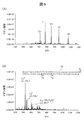
- FIG. 7 is a diagram showing an analysis result of substance P (molecular weight 1347).
- 7A shows a mass spectrum before decomposition of the substance P
- FIG. 7B shows a mass spectrum after decomposition of the substance P.
- FIG. 7A shows an analysis result when the temperature of the heating pipe 10 is adjusted to 80 ° C.
- FIG. 7B shows an analysis result when the temperature is adjusted to 220 ° C.
- the experimental conditions are that the upstream pressure of the separation column 6 is 3.5 MPa, and the mobile phase passage time of the heating pipe 10 is 30 seconds. Further, 0.1% acetic acid water was used for the mobile phase when the sample was adsorbed on the separation column 6, and methanol containing 0.1% acetic acid was used when the sample was eluted.
- the fragment ions of y6 and y7 derived from substance P could be detected.
- the site of decomposition by heating is shown in the amino acid sequence 21 of substance P.
- FIG. 8 is a diagram showing an analysis result of ubiquitin (molecular weight 8560).
- FIG. 8A shows a mass spectrum before decomposition of ubiquitin
- FIG. 8B shows a mass spectrum after decomposition of ubiquitin.
- FIG. 8A shows an analysis result when the temperature of the heating pipe 10 is adjusted to 80 ° C.
- FIG. 8B shows an analysis result when the temperature is adjusted to 180 ° C.
- the experimental conditions are that the upstream pressure of the separation column 6 is 1.6 MPa, and the mobile phase passage time of the heating pipe 10 is 30 seconds.
- FIG. 9 is a diagram illustrating protein hydrolysis using a structural formula.
- the protein 64 before hydrolysis takes in water (H 2 O), so that the peptide bond is cut and is degraded like the protein 65 after hydrolysis. Since the y-series ions derived from fragments generated by the cleavage of the peptide bond are detected in both substance P and ubiquitin analysis results, it is understood that hydrolysis can be performed in a short time according to this example. It was.
- FIG. 10 is a schematic diagram illustrating a configuration example of the sample fragmentation apparatus 1 according to the third embodiment.
- a configuration will be described in which the flow path between the heating unit 4 and the separation column 6 is branched and the pressure is adjusted in the flow path system of the sample fragmentation apparatus.
- the configuration of FIG. 10 is characterized in that the pressure adjustment unit 5 includes a flow path switching valve 25 and a flow path conductance adjustment unit 26.
- the flow path switching valve 25 By installing the flow path switching valve 25 in front of the separation column 6, the flow path connected to the subsequent stage of the heating unit 4 can be switched to the separation column 6 side or the conductance adjustment unit 26 side.
- the flow path switching valve 25 opens the port on the conductance adjustment unit 26 side and flows the mobile phase in the direction of the arrow 31.
- the conductance adjusting unit 26 controls the flow path switching valve 25 to set the optimum conditions for hydrolysis of proteins and the like.
- the mobile phase flowing in the direction of the arrow 31 passes through the conductance adjusting unit 26 and is discarded to the discarding unit 27.
- the channel switching valve 25 opens the port on the separation column 6 side and moves in the direction of the arrow 30. Run the phase.
- the mobile phase flowing in the direction of the arrow 30 includes sample components such as proteins fragmented by hydrolysis, and these sample components are adsorbed on the stationary phase of the separation column 6.
- the adsorbed sample components are eluted in the subsequent elution step, ionized by the ion source 7, and the generated ions 11 are detected by the mass spectrometer 8.
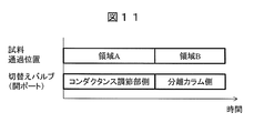
- the flow path connected to the heating unit 4, that is, the open port of the flow path switching valve 25 depends on the elapsed time from the start of feeding the sample by the liquid feeding pump 2, that is, the separation column 6 and the conductance adjustment unit 26. By switching between them, it is possible to control the pressure conditions optimal for hydrolysis only at the timing when the sample passes through the region A (inside the heating pipe 10). By this method, since the pressure at the time of performing the hydrolysis in the heating pipe 10 is not applied to the separation column 6, unnecessary pressure other than the pressure necessary for sample separation is not applied to the separation column 6. Therefore, the lifetime of the separation column 6 is extended.
- Example 4 describes a configuration in which the flow path between the heating pipe and the separation column is switched in the flow path system of the sample fragmentation apparatus, and the mobile phase is supplied from different flow paths in the adsorption and elution processes.
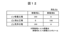
- FIG. 12 is a diagram showing an example of experimental conditions used in liquid chromatography.
- the experimental conditions shown in FIG. 12 are as follows: 100% mobile phase A (0.1% aqueous acetic acid) is flowed in the adsorption step, and 100% mobile phase B (0.1% acetic acid methanol) is flowed in the elution step. Then, let mobile phase A flow 100%.
- the ratio of the mobile phase A and the mobile phase B is appropriately changed depending on the sample to be analyzed and the type of the separation column.
- another solvent such as acetonitrile may be used depending on the application, or another substance such as formic acid may be added in addition to acetic acid.
- FIG. 5 a sample of reserpine (concentration: 1 ppb) dissolved in a methanol solvent is sent to the separation column 6 at a rate of 100 ⁇ L / min by continuous feeding (infusion), and the ion source 7 (ESI method)
- the ion 11 produced by ionization was analyzed with the mass spectrometer 8.
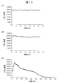
- the analysis results are shown in FIG.
- the mass spectrometer 8 used was a triple quadrupole mass spectrometer (QqQ) and used a multi-reaction monitoring (MRM) mode.
- FIG. 13 shows experimental results when the MRM setting is changed from m / z 609 to m / z 195.
- FIG. 13A shows the experimental results when the temperature of the heating pipe 10 is room temperature
- FIG. FIG. 13 (C) shows the experimental results at 100 ° C.
- FIG. 13 (A) room temperature
- FIG. 13 (B) 90 ° C.
- FIG. 13 (C) 100 ° C.
- the fluctuation of ionic strength is very large. This is because the methanol solution is boiling, and performing the adsorption step and the elution step under the same pressure and temperature conditions in the configuration of FIG. 5 may impair the measurement stability.
- the configuration of the sample fragmentation apparatus 1 shown in FIG. 14 is almost the same as that in FIGS. 1 and 5, and only the differences will be described.
- the configuration of FIG. 14 is characterized in that the pressure adjusting unit 5 includes a flow path switching valve 25 and a conductance adjusting section 26, and the mobile phase is supplied from different flow paths in the adsorption and elution processes by the flow path switching valve 25. To do. That is, the flow path switching valve 25 switches the flow path connected to the inflow side of the separation column 6 between a flow path that passes through the heating unit 4 and a flow path that does not pass through the heating unit 4.
- the flow path switching valve 25 is controlled so that the mobile phase A flows from the direction of the arrow 37 to the separation column 6 side through the heating unit 4, and in the elution process, the mobile phase B Controls the flow path switching valve 25 so as to flow from the direction of the arrow 38 to the separation column 6 side without passing through the heating unit 4.
- the mobile phase B having a low boiling point can be introduced from the unheated flow path. Unstable operation during elution can be prevented.
- FIG. 14 shows a configuration in which the flow path switching valve 25 is in the front stage of the conductance adjusting unit 26, the same effect can be obtained even if the flow path switching valve 25 is in the subsequent stage of the conductance adjusting section 26.
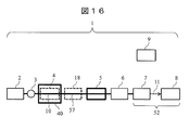
- FIG. 16 is a schematic diagram illustrating a configuration example of the sample fragmentation apparatus 1 according to the fifth embodiment.
- a configuration having a cooling unit for cooling the heating pipe in the flow path system of the sample fragmentation apparatus will be described.
- FIG. 16 is almost the same as that shown in FIGS. 1 and 5, and only the differences will be described.
- the configuration shown in FIG. 16 is characterized in that a cooling unit 40 that cools the heating pipe 10 is added to the heating unit 4.
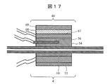
- FIG. 17 is a schematic cross-sectional view showing a structural example in which the cooling unit 40 is provided in addition to the heating unit 4.
- the heating mechanism of the heating unit 4 is substantially the same as that in FIG.
- a Peltier element 67 was disposed.
- a heat sink 68 and a fan 69 are preferably provided.
- the same effect can be obtained even if other configurations are used as long as the heating pipe 10 can be cooled, such as a configuration such as a water jacket or a configuration in which cooling is directly performed by a cooling fan. Is possible.
- the same effect as in Embodiment 4 can be obtained.
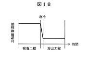
- the heating pipe 10 heated by the heating unit 4 is used between an adsorption step for adsorbing a sample on the separation column and an elution step for eluting the sample adsorbed on the separation column with an elution solvent.
- the cooling unit 40 By rapidly cooling the temperature to a temperature equal to or lower than the boiling point of the elution solvent by the cooling unit 40, it is possible to prevent the mobile phase (elution solvent) from boiling in the elution step.
- Example 6 In the sixth embodiment, a configuration in which the heating pipe pressure is controlled by the pressure adjusting unit during the adsorption and elution processes in the flow path system of the sample fragmentation apparatus will be described. Since the apparatus configuration can be applied to all the embodiments described so far, only the features of this embodiment will be described.
- FIG. 19 is a diagram showing a time sequence of the present embodiment.
- the control unit 9 controls the pressure adjusting unit 5 to increase the internal pressure of the heating pipe 10.
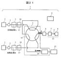
- Example 7 20 and 21 are schematic diagrams illustrating a configuration example of the sample fragmentation apparatus 1 according to the seventh embodiment.
- a description will be given of a configuration example in which a plurality of heating pipes are provided in a flow path system of a sample fragmentation apparatus, and sample fragmentation by hydrolysis is performed in parallel.
- the operating principle of this embodiment is almost the same as the operating principle shown in FIG. 10, so only the differences will be described.
- the configuration of this embodiment is characterized in that the pressure adjusting unit 5 has a six-way valve 45 and a conductance adjusting unit 26. 20 and 21 show the connection state of each flow path when the six-way valve 45 is switched.
- the six-way valve 45 is similar to the channel switching valve 25 in FIG. 10 in terms of the function of switching the channel, but by using the six-way valve 45, a plurality of heating pipes (heating pipe A and heating pipe B) can be used. It becomes possible to respond.
- FIG. 20 shows a state in which the heating pipe A is connected to the separation column 6 side by the hexagonal valve 45 and the mobile phase on the heating pipe A side flows as indicated by an arrow A.
- the heating pipe B is connected to the conductance adjusting unit 26 side by a hexagonal valve 45, and the mobile phase on the heating pipe B side flows as shown by an arrow B.
- the heating pipe B is controlled to an optimum pressure condition by the conductance adjusting unit 26, and the sample is hydrolyzed by the heating pipe B of the heating unit under pressure control.
- the six-way valve 45 is switched.
- the heating pipe B is connected to the separation column 6 side as shown in FIG. 21, and the mobile phase on the heating pipe B side flows to the separation column 6 as indicated by the arrow A.
- the heating pipe A is connected to the conductance adjusting unit 26 side, and the mobile phase on the heating pipe A side flows as shown by an arrow B.
- the heating pipe A is controlled to an optimum pressure condition by the conductance adjusting section 26, and the sample is hydrolyzed by the heating pipe A of the heating section under pressure control.
- the mobile phase from the heating pipe A flows to the conductance adjusting unit 26 as indicated by the arrow B, and the mobile phase from the heating pipe B is supplied to the separation column 6 as indicated by the arrow A.
- the mobile phase from the heating pipe B flows to the conductance adjusting unit 26 as indicated by the arrow B, and the mobile phase from the heating pipe A is separated from the separation column 6 as indicated by the arrow A. (FIG. 22).
- the present Example demonstrated in the example using several liquid feeding pumps 2 and several sample injection
- the flow path may be branched from the sample injection section, and the sample may be introduced into the heating pipe A and the heating pipe B.
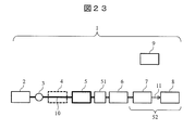
- FIG. 23 is a schematic diagram illustrating a configuration example of the sample fragmentation apparatus 1 according to the eighth embodiment. In this example, a configuration having a filter in front of the separation column in the flow path system of the sample fragmentation apparatus will be described.
- FIG. 23 is almost the same as that in FIG. 1, and only the differences will be described.
- the configuration of FIG. 23 is characterized in that a filter 51 is provided in front of the separation column 6.
- insoluble substances may be generated due to denaturation. Since insoluble substances are difficult to dissolve in the mobile phase, they may not pass through the packing of the separation column 6 and may be clogged. The clogging of the separation column 6 not only abnormally increases the flow path pressure but also may shorten the life of the separation column 6.
- the filter 51 by arranging the filter 51 in the preceding stage of the separation column 6, it is possible to suppress introduction of insoluble substances that may be generated in the heating pipe 10 into the separation column 6.
- a guard column, a pre-column filter, or the like can be used as the filter 51.
- the filter 51 can also be used as the pressure adjusting unit 5 or the conductance adjusting unit 26.
- FIG. 24 is a schematic diagram illustrating a configuration example of the sample fragmentation apparatus 1 according to the ninth embodiment. In this example, a configuration using an ultraviolet-visible light detector as a detector in the sample fragmentation apparatus will be described.
- FIG. 24 Since the configuration of FIG. 24 is almost the same as that of FIG. 1, only the differences will be described.
- the configuration of FIG. 24 is characterized by using an ultraviolet-visible light detector 53 as a detector.
- UV-visible light detector 53 By using the UV-visible light detector 53, it is possible to deal with a sample having a large ion suppression or a sample having a low ionization efficiency in the analysis by the mass spectrometry method.
- this invention is not limited to the above-mentioned Example, Various modifications are included.
- the above-described embodiments have been described in detail for easy understanding of the present invention, and are not necessarily limited to those having all the configurations described.
- a part of the configuration of one embodiment can be replaced with the configuration of another embodiment, and the configuration of another embodiment can be added to the configuration of one embodiment.
- various detection methods such as a photodiode array detector and a fluorescence detector can be used as the detector.
Landscapes
- Chemical & Material Sciences (AREA)
- Analytical Chemistry (AREA)
- Physics & Mathematics (AREA)
- Health & Medical Sciences (AREA)
- Life Sciences & Earth Sciences (AREA)
- Biochemistry (AREA)
- General Health & Medical Sciences (AREA)
- General Physics & Mathematics (AREA)
- Immunology (AREA)
- Pathology (AREA)
- Chemical Kinetics & Catalysis (AREA)
- Other Investigation Or Analysis Of Materials By Electrical Means (AREA)
Abstract
Description
図1は、実施例1の試料断片化装置の構成例を示す模式図である。本実施例では、試料断片化装置の流路系内で、加熱配管と分離カラムの間に圧力調節部を有する構成について説明する。ここでは、検出器に質量分析計を用いた例を示す。

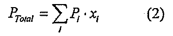
図5は、実施例2による試料断片化装置の構成例を示す模式図である。本実施例では、試料断片化装置の流路系内で、加熱部4と分離カラム6の間に冷却部18を有する構成について説明する。
図10は、実施例3の試料断片化装置1の構成例を示す模式図である。本実施例では、試料断片化装置の流路系内で、加熱部4と分離カラム6の間の流路を分岐し、圧力調節を行う構成について説明する。
実施例4では、試料断片化装置の流路系内で、加熱配管と分離カラムの間の流路を切替えて、吸着と溶出の工程で異なる流路から移動相を供給する構成について説明する。
図16は、実施例5の試料断片化装置1の構成例を示す模式図である。本実施例では、試料断片化装置の流路系内で、加熱配管を冷却する冷却部を有する構成について説明する。
実施例6では、試料断片化装置の流路系内で、吸着と溶出の工程の間に、圧力調節部により加熱配管圧力を制御する構成について説明する。装置構成については、これまで述べてきた実施例の全てにおいて適用可能であるので、本実施例の特徴のみを説明する。
図20、図21は、実施例7の試料断片化装置1の構成例を示す模式図である。本実施例では、試料断片化装置の流路系内に複数の加熱配管を設け、加水分解による試料の断片化を並列で行う構成例について説明する。
図23は、実施例8の試料断片化装置1の構成例を示す模式図である。本実施例では、試料断片化装置の流路系内で、分離カラムの前にフィルタを有する構成について説明する。
図24は、実施例9の試料断片化装置1の構成例を示す模式図である。本実施例では、試料断片化装置において、検出器に紫外可視光検出器を用いた構成について説明する。
2 送液ポンプ
3 試料注入部
4 加熱部
5 圧力調節部
6 分離カラム
7 イオン源
8 質量分析計
9 制御部
10 加熱配管
11 イオン
18 冷却部
25 流路切替バルブ
26 コンダクタンス調節部
27 廃棄部
40 冷却部
45 六方バルブ
51 フィルタ
52 検出器
53 紫外可視光検出器
54 加熱ブロック
55 ヒータ
56 熱電対
57 配管
58 液体
59 容器
62 熱電対
63 ヒータ
67 ペルチェ素子
68 ヒートシンク
69 ファン
Claims (10)
- 配管により接続された送液ポンプ、試料注入部及び分離カラムと、
前記試料注入部と前記分離カラムの間の配管を加熱する加熱部と、
前記加熱部と前記分離カラムの間に設けられ、前記加熱部により加熱される配管の内部圧力を調節する圧力調節部と、
を有する試料断片化装置。 - 前記加熱部と前記分離カラムの間の配管を冷却する冷却部を有する、請求項1記載の試料断片化装置。
- 前記加熱部は、当該加熱部により加熱された配管を冷却する冷却部を備える、請求項1記載の試料断片化装置。
- 前記冷却部は、溶出用溶媒により前記分離カラムに吸着した試料を溶出する際に、前記加熱部により加熱された配管を前記溶出用溶媒の沸点以下の温度に冷却する、請求項3記載の試料断片化装置。
- 前記圧力調節部は流路切替バルブとコンダクタンス調節部を備え、前記流路切替バルブは前記加熱部に接続される流路を前記分離カラムと前記コンダクタンス調節部との間で切り替える、請求項1記載の試料断片化装置。
- 前記送液ポンプで試料を送り始めてからの経過時間に依存して前記流路切替バルブを切り替える、請求項5記載の試料断片化装置。
- 前記加熱部を備える配管を複数有し、前記流路切替バルブは前記複数の加熱部に接続される流路を前記分離カラムと前記コンダクタンス調節部に順次切り替える、請求項5記載の試料断片化装置。
- 前記圧力調節部は流路切替バルブとコンダクタンス調節部を備え、前記流路切替バルブは前記分離カラムに接続される流路を前記加熱部を通る流路と前記加熱部を通らない流路との間で切り替える、請求項1記載の試料断片化装置。
- 前記送液ポンプで試料を送り始めてからの経過時間に依存して前記流路切替バルブを切り替える、請求項8記載の試料断片化装置。
- 前記圧力調節部は、溶出用溶媒により前記分離カラムに吸着した試料を溶出する際に、前記加熱部により加熱された配管の内部圧力を増加させて前記溶出用溶媒の沸騰を防止する、請求項1記載の試料断片化装置。
Priority Applications (3)
| Application Number | Priority Date | Filing Date | Title |
|---|---|---|---|
| GB1717440.0A GB2555537B (en) | 2015-05-19 | 2016-03-30 | Sample Fragmentation Device |
| DE112016002283.2T DE112016002283T5 (de) | 2015-05-19 | 2016-03-30 | Probenfragmentierungseinrichtung |
| US15/568,529 US11101121B2 (en) | 2015-05-19 | 2016-03-30 | Sample fragmentation device using heating and pressure regulation between sample injector and separation column |
Applications Claiming Priority (2)
| Application Number | Priority Date | Filing Date | Title |
|---|---|---|---|
| JP2015-102037 | 2015-05-19 | ||
| JP2015102037A JP6654000B2 (ja) | 2015-05-19 | 2015-05-19 | 試料断片化装置 |
Publications (1)
| Publication Number | Publication Date |
|---|---|
| WO2016185807A1 true WO2016185807A1 (ja) | 2016-11-24 |
Family
ID=57319838
Family Applications (1)
| Application Number | Title | Priority Date | Filing Date |
|---|---|---|---|
| PCT/JP2016/060579 Ceased WO2016185807A1 (ja) | 2015-05-19 | 2016-03-30 | 試料断片化装置 |
Country Status (5)
| Country | Link |
|---|---|
| US (1) | US11101121B2 (ja) |
| JP (1) | JP6654000B2 (ja) |
| DE (1) | DE112016002283T5 (ja) |
| GB (1) | GB2555537B (ja) |
| WO (1) | WO2016185807A1 (ja) |
Families Citing this family (1)
| Publication number | Priority date | Publication date | Assignee | Title |
|---|---|---|---|---|
| CA3151967A1 (en) * | 2019-09-23 | 2021-04-01 | Marina Hincapie | Product quality attribute measurement |
Citations (2)
| Publication number | Priority date | Publication date | Assignee | Title |
|---|---|---|---|---|
| JPH06184068A (ja) * | 1992-12-24 | 1994-07-05 | Seiko Instr Inc | タンパク質あるいはペプチドを加水分解する装置 |
| JP2002139500A (ja) * | 2000-10-31 | 2002-05-17 | Asahi Tekuneion Kk | タンパク質又はぺプチドのアミノ酸配列を決定する方法およびその装置 |
Family Cites Families (15)
| Publication number | Priority date | Publication date | Assignee | Title |
|---|---|---|---|---|
| US4699768A (en) * | 1983-09-09 | 1987-10-13 | Technicon Instruments Corporation | Apparatus for exchanging substances between fluids |
| DE69637079T2 (de) * | 1995-10-16 | 2008-01-24 | Thermo Orion Inc., Beverly | Hochgeschwindigkeitschromatographie |
| US5954860A (en) * | 1997-10-23 | 1999-09-21 | Hewlett-Packard Company | Inductively heated cold-trap analyte injector |
| DE19810109C2 (de) * | 1998-03-10 | 2000-02-10 | Gerstel Gmbh & Co Kg | Gaschromatograph mit einem temperaturgesteuerten Injektor |
| SE515567C2 (sv) * | 1999-10-27 | 2001-08-27 | Esy Tech Ab | Vätske-vätskeextraktion och direkt överföring av analyten till gaskromatografiapparat |
| ES2369636T3 (es) * | 2000-01-12 | 2011-12-02 | Zoex Licensing Corporation | Modulación térmica transversal. |
| JP2002014080A (ja) * | 2000-06-28 | 2002-01-18 | Mitsubishi Electric Corp | 発電機内部冷却ガスの監視装置および監視システム |
| US20030085714A1 (en) * | 2001-11-05 | 2003-05-08 | Keyes Marion A. | Mass flow control in a process gas analyzer |
| JP2003331776A (ja) * | 2002-05-10 | 2003-11-21 | Hitachi Ltd | イオン源および質量分析装置および質量分析方法 |
| EP1751537B1 (en) * | 2004-05-17 | 2019-07-10 | Firmenich SA | Multidimensional gas chromatography apparatus and analyte transfer procedure using a multiple-cool strand interface |
| JP4783891B2 (ja) * | 2006-09-05 | 2011-09-28 | 独立行政法人産業技術総合研究所 | ガスクロマトグラフに誘導結合プラズマ質量分析装置を結合させた分析装置 |
| JP5002365B2 (ja) * | 2007-08-06 | 2012-08-15 | 株式会社日立製作所 | 質量分析装置及び質量分析方法 |
| US8999245B2 (en) * | 2009-07-07 | 2015-04-07 | Tricorn Tech Corporation | Cascaded gas chromatographs (CGCs) with individual temperature control and gas analysis systems using same |
| US8277544B2 (en) * | 2010-03-26 | 2012-10-02 | Agilent Technologies, Inc. | Thermal modulation device for two dimensional gas chromatography |
| PE20131039A1 (es) * | 2010-07-19 | 2013-10-12 | Sgs North America Inc | Analisis automatizado de fluidos presurizados en yacimientos |
-
2015
- 2015-05-19 JP JP2015102037A patent/JP6654000B2/ja active Active
-
2016
- 2016-03-30 US US15/568,529 patent/US11101121B2/en active Active
- 2016-03-30 WO PCT/JP2016/060579 patent/WO2016185807A1/ja not_active Ceased
- 2016-03-30 DE DE112016002283.2T patent/DE112016002283T5/de active Pending
- 2016-03-30 GB GB1717440.0A patent/GB2555537B/en active Active
Patent Citations (2)
| Publication number | Priority date | Publication date | Assignee | Title |
|---|---|---|---|---|
| JPH06184068A (ja) * | 1992-12-24 | 1994-07-05 | Seiko Instr Inc | タンパク質あるいはペプチドを加水分解する装置 |
| JP2002139500A (ja) * | 2000-10-31 | 2002-05-17 | Asahi Tekuneion Kk | タンパク質又はぺプチドのアミノ酸配列を決定する方法およびその装置 |
Also Published As
| Publication number | Publication date |
|---|---|
| JP2016217836A (ja) | 2016-12-22 |
| GB2555537A (en) | 2018-05-02 |
| GB201717440D0 (en) | 2017-12-06 |
| US20180114682A1 (en) | 2018-04-26 |
| US11101121B2 (en) | 2021-08-24 |
| JP6654000B2 (ja) | 2020-02-26 |
| DE112016002283T5 (de) | 2018-02-15 |
| GB2555537B (en) | 2020-08-19 |
Similar Documents
| Publication | Publication Date | Title |
|---|---|---|
| US5015845A (en) | Electrospray method for mass spectrometry | |
| US9150610B2 (en) | Method and apparatus to perform hydrogen-deuterium exchange | |
| JP6667248B2 (ja) | ポストカラム調節剤およびマイクロ流体デバイスを使用したエレクトロスプレーイオン化質量分析における検出の感度強化 | |
| JPH03138561A (ja) | クロマトグラフ・システム | |
| CN102903596B (zh) | 一种离子源温控加热装置 | |
| US8410434B1 (en) | Thermo-stabilized nano- and micro- flow LC/ESI-MS interface and a method thereof | |
| US9947521B2 (en) | Auxiliary gas inlet | |
| WO2013112680A1 (en) | Ionization at intermediate pressure for atmospheric pressure ionization mass spectrometers | |
| EP2356441B1 (en) | Dynamic thermal focusing of chromatographic separations | |
| US8779356B2 (en) | Method and system for providing a dual curtain gas to a mass spectrometry system | |
| KR101701998B1 (ko) | 기체크로마토그래피-전기분무/고분해능 질량분석기와 이를 이용한 기체상태 유기화합물의 이온화 방법 | |
| US9881779B2 (en) | Auxiliary gas inlet | |
| JP6654000B2 (ja) | 試料断片化装置 | |
| US7547555B2 (en) | Use of temperature and flow profiles in gradient elution based analytical process | |
| CN211122658U (zh) | 有机和无机混合气体快速定量分析质谱仪 | |
| US9976995B2 (en) | Staggered chromatography mass spectrometry | |
| US11092579B2 (en) | Machine for chemical analysis comprising the combination of electron ionization mass spectrometry with liquid chromatography | |
| US20140264003A1 (en) | Method for Cleaning an Atmospheric Pressure Chemical Ionization Source | |
| CN112119310B (zh) | 通过质谱检测嗜铬粒蛋白a的方法 | |
| WO2019200388A1 (en) | Mass spectrometer ion source with integrated column | |
| Chen | A brief review of interfacing supercritical fluid chromatography with mass spectrometry | |
| EP3047506A1 (en) | Automated adjustment of capillary voltage based on the elution conditions to retain optimal ionization conditions | |
| CN111965292A (zh) | 多维双通道的液相色谱-质谱联用装置 | |
| US20200209199A1 (en) | Supercritical fluid apparatus | |
| US20130240180A1 (en) | System and method for superheating and/or supercooling of liquids and use of the system and/or method |
Legal Events
| Date | Code | Title | Description |
|---|---|---|---|
| 121 | Ep: the epo has been informed by wipo that ep was designated in this application |
Ref document number: 16796201 Country of ref document: EP Kind code of ref document: A1 |
|
| WWE | Wipo information: entry into national phase |
Ref document number: 15568529 Country of ref document: US |
|
| ENP | Entry into the national phase |
Ref document number: 201717440 Country of ref document: GB Kind code of ref document: A Free format text: PCT FILING DATE = 20160330 |
|
| WWE | Wipo information: entry into national phase |
Ref document number: 112016002283 Country of ref document: DE |
|
| 122 | Ep: pct application non-entry in european phase |
Ref document number: 16796201 Country of ref document: EP Kind code of ref document: A1 |