WO2016184484A1 - Wheel assembly for a vacuum cleaner and vacuum cleaner comprising said wheel assembly - Google Patents
Wheel assembly for a vacuum cleaner and vacuum cleaner comprising said wheel assembly Download PDFInfo
- Publication number
- WO2016184484A1 WO2016184484A1 PCT/EP2015/060773 EP2015060773W WO2016184484A1 WO 2016184484 A1 WO2016184484 A1 WO 2016184484A1 EP 2015060773 W EP2015060773 W EP 2015060773W WO 2016184484 A1 WO2016184484 A1 WO 2016184484A1
- Authority
- WO
- WIPO (PCT)
- Prior art keywords
- carrier
- wheel assembly
- wheel
- support surface
- bearing elements
- Prior art date
- Legal status (The legal status is an assumption and is not a legal conclusion. Google has not performed a legal analysis and makes no representation as to the accuracy of the status listed.)
- Ceased
Links
Images

Classifications
-
- A—HUMAN NECESSITIES
- A47—FURNITURE; DOMESTIC ARTICLES OR APPLIANCES; COFFEE MILLS; SPICE MILLS; SUCTION CLEANERS IN GENERAL
- A47L—DOMESTIC WASHING OR CLEANING; SUCTION CLEANERS IN GENERAL
- A47L9/00—Details or accessories of suction cleaners, e.g. mechanical means for controlling the suction or for effecting pulsating action; Storing devices specially adapted to suction cleaners or parts thereof; Carrying-vehicles specially adapted for suction cleaners
- A47L9/009—Carrying-vehicles; Arrangements of trollies or wheels; Means for avoiding mechanical obstacles
Definitions
- the present invention relates to a wheel assembly for a vacuum cleaner and to a vacuum cleaner, in particular a canister vacuum cleaner, comprising the above mentioned wheel assembly.
- the canister vacuum cleaners generally comprise a body, mounted on wheels, and a suction head connected to the body by a flexible suction hose.
- Each of the wheels is usually mounted on the body by means of a central axle or spindle about which the wheel rotates.
- the wheels assembly therein disclosed comprises a carrier, a wheel and a retaining member, which holds the wheel on the carrier by releasably engaging the carrier.
- the retaining member comprises a continuous annular bearing surface with which a complementary continuous annular bearing surface of the wheel cooperates to support the wheel for the rotation.
- the main drawback of the vacuum cleaner disclosed in document WO 12153146 resides on the fact that the coupling between the continuous annular bearing surfaces of the retaining member and of the wheel is affected by possible misalignments that could derive from the manufacturing process.
- the object of the present invention is to provide a wheel assembly which ensures an optimal axial and radial alignment of the wheels.
- a further object of the present invention is to provide a vacuum cleaner, comprising the above mentioned wheel assembly, which is sturdy and has an optimal movability.
- the carrier intended to be fixed to the body of the vacuum cleaner and having a support surface for supporting a wheel, comprises a plurality of bearing elements extending radially and outwardly from the support surface, on which bearing elements a coupling surface of the wheel slides while the wheel is rotating.
- the bearing elements are designed and are supported on the support surface of the carrier so as to be elastically compressible in a direction perpendicular to the support surface.
- each of the bearing elements is elastically compressible independently of the remaining bearing elements.
- each of the bearing elements has a convex form toward the coupling surface of the wheel.
- each of the bearing elements is a flat spring.
- the bearing elements are physically separate and the carrier comprises, circumferentially spaced on its support surface, a plurality of recesses on each of which one of the bearing elements is mounted.
- the carrier comprises a ring-shaped body arranged on the support surface and comprising the bearing elements, which hence are connected one to the other.
- the carrier further comprises aligning means for the axial alignment of the wheel.
- the aligning means comprises a plurality of retaining elements extending radially, perpendicular to the support surface, from an edge of the support surface. The retaining elements abut the wheel, thus retaining it with its coupling surface aligned with the support surface.
- each of the bearing elements is a roller.
- the support surface of the carrier is inclined with respect to the rotation axis and each of the rollers is mounted on the support surface with its rotation axis extending parallel to the support surface along the radial direction.
- the carrier comprises a first central through hole and the wheel comprises a second central through hole aligned to the first central through hole of the carrier and intended to be aligned to an opening on the body of the vacuum cleaner when the carrier is fixed to the body.
- the wheel assembly further comprises a cover detachably engaged to the carrier for closing the aligned first central through hole of the carrier and second central through hole of the wheel and therefore for closing the opening on the body of the vacuum cleaner when the wheel assembly is mounted on it.
- the cover is rotationally engageable to the carrier.
- a vacuum cleaner comprising a body and a wheel assembly according to the invention mounted on the body, with the carrier of the wheel assembly fixed to the body of the vacuum cleaner.
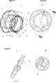
- Figure 1 is a perspective exploded view of a first embodiment of a wheel assembly according to the present invention.
- Figures 2 and 3 are respectively a front and a rear perspective view of a particular of the wheel assembly of Figure 1 relative to a carrier, partially exploded.
- Figure 4 is a perspective exploded view of the carrier of a second embodiment of the wheel assembly according to the present invention.
- Figure 5 is a plan view of a further particular of the first and second embodiment of the wheel assembly according to the present invention, relative to a cover.
- Figure 6 is a cross-sectional view of the cover of Figure 5 taken from the line A-A, with an enlarged particular.
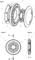
- Figure 7 is a perspective exploded view of a third embodiment of a wheel assembly according to the present invention.
- Figure 8 is a plan view of the wheel assembly of Figure 7.
- Figure 9 is a cross sectional view of the wheel assembly of Figure 8 taken from the line B-B.
- the wheel assembly 1 is designed for a vacuum cleaner, and in particular for a canister vacuum cleaner, which comprises a body on which wheels are rotatably mounted.
- the wheel assembly 1 comprises a carrier 2, intended to be fixed to the body of the vacuum cleaner, having an annular shape and comprising an annular support surface 3.
- the wheel assembly 1 further comprises a wheel 4 coaxially mounted on the carrier 2 around a rotation axis X and having a coupling surface 5 facing the support surface 3 of the carrier 2. More in detail, the support surface 3 of the carrier 2 and the coupling surface 5 of the wheel 4 extend parallel to each other.
- the support surface 3 of the carrier 2 and the coupling surface 5 of the wheel 4 extend parallel to the rotation axis X of the wheel 4, as illustrated in Figures 1-4 attached.
- the support surface 3 and the coupling surface 5 are inclined with respect to the rotation axis X, as illustrated in Figures 7-9 attached.
- the carrier 2 comprises a plurality of bearing elements 6 which extend radially from the support surface 3, circumferentially spaced along the support surface 3, and which co-operate with the coupling surface 5 of the wheel 4 to support the wheel 4 for the rotation. Therefore the wheel 4 rotates with respect to the carrier 2, which remains fix, with its coupling surface 5 that slides on the bearing elements 6.
- bearing elements 6 extend outward from the support surface 3, toward the coupling surface 5 of the wheel 4.
- the presence of the bearing elements 6 on the support surface 3 of the carrier 2 allows to reduce the contact area between the support surface 3 and the coupling surface 5, ensuring a better coupling between the wheel 4 and the carrier 2 even in the presence of misalignments of the support surface 3 and of the coupling surface 5.
- the bearing elements 6 are elastically compressible in a direction perpendicular to the support surface 3. More in detail, according to the embodiment illustrated in Figures 1-4 attached, the bearing elements 6 are elastically compressible in the radial direction r, while according to the embodiment illustrated in Figures 7-9 attached, the bearing elements 6 are elastically compressible in an inclined direction perpendicular to the inclined support surface 3.
- each of the bearing elements 6 is elastically compressible in a direction perpendicular to the support surface 3 independently of the remaining bearing elements 6. This allows to compensate possible local misalignment of the support surface 3 and of the coupling surface 5 which may derive for instance from the manufacturing process, still ensuring an optimal coupling between the carrier 2 and the wheel 4.
- each of the bearing elements 6 has an outwardly convex form, i.e. a convex form toward the coupling surface 5 of the wheel 4.
- the convex form of the bearing elements 6 reduces the contact surface between the support surface 3 of the carrier 2 and the coupling surface 5 of the wheel 4 allowing the wheel 4 to easily and smoothly slide on the carrier 2.
- each of the bearing elements 6 is a flat spring.
- the bearing elements 6 are distinct elements and the carrier 2 comprises, circumferentially spaced on its support surface 3, a plurality of recesses 7 on each of which one of the bearing elements 6 is mounted.
- the carrier 2 comprises, circumferentially spaced on its support surface 3, a plurality of recesses 7 on each of which one of the bearing elements 6 is mounted.
- the carrier 2 comprises a ring-shaped body 8 arranged on the support surface 3 and comprising the bearing elements 6.
- the bearing elements 6 are defined by convex shaped and circumferentially spaced portions of the ring-shaped body 8.
- This embodiment of the wheel assembly 1 allows to faster assemble the wheel 4 and the carrier 2, since once the wheel 4 has been mounted on the carrier 2, it is sufficient to place the ring-shaped body 8 between the support surface 3 and the coupling surface 5 thus mounting all the bearing elements 6 simultaneously.
- the support surface 3 and the ring-shaped body 8 comprise respectively anti-rotation protrusions and nooks, as illustrated in Figure 4, which are counter-shaped so as to engage each other when the ring-shaped body 8 is arranged on the support surface 3, thus preventing the ring-shaped body 8 from rotating with respect to the support surface 3.
- the carrier 2 further comprises aligning means 9 for the axial alignment of the wheel 4.
- the aligning means 9 allows to retain the coupling surface 5 of the wheel 4 facing the support surface 3 of the carrier 2, avoiding that the wheel 4 might become offset with respect to the carrier 2 in directions parallel to the rotation axis X.
- the aligning means 9 comprises a plurality of retaining elements 10 extending radially, perpendicular to the support surface 3, from an edge of the support surface 3, for retaining the wheel 4 with its coupling surface 5 aligned to the support surface 3.
- the retaining elements 10 are in particular mounted on the support surface 3 of the carrier 2. The retaining elements 10 hinder the sliding of the wheel 4 on the carrier 2 on a direction parallel to the rotation axis X.
- the retaining elements 10 are associated to the bearing elements 6 and, more in detail, each of the retaining elements 10 is associated to a corresponding bearing element 6.
- the retaining elements 10 form a single body with the bearing elements 6.
- the carrier 2 comprises a flange 11 extending radially, perpendicular to the support surface 3, from one edge of the support surface 3.
- the retaining elements 10 extend radially from the opposite edge of the support surface 3.
- the aligning means 9 comprises elastically deformable counter-retaining elements 12 associated to the flange 11 of the carrier 2, which are elastically deformed when the wheel 4 is coupled to the carrier 2, thus exerting on the wheel 4 a reaction force that pushes the wheel 4 against the retaining elements 10.
- the counter-retaining elements 12 are releasably fastened to the flange 11 of the carrier 2.
- each of the bearing elements 6 is a roller.
- the support surface 3 of the carrier 2 is inclined with respect to the rotation axis X and each of the rollers is mounted on the support surface 3 with its rotation axis Y extending parallel to the support surface 3 along the radial direction.
- the rollers are axially supported on the support surface 3 by elastic means that allows the rollers to be elastically compressed in a direction perpendicular to the support surface 3, i.e. more clearly to be reversibly shifted with respect to the support surface 3 in a direction perpendicular to the latter.
- the bearing elements 6 are made of polyoxymethylene (POM), which confers to the bearing elements 6 both low friction and a high stiffness.
- POM polyoxymethylene
- the carrier 2 comprises a first central through hole 13 and the wheel 4 comprises a second central through hole 14 aligned to the first central through hole 13 of the carrier 2 and intended to be aligned to an opening on the body of the vacuum cleaner when the carrier 2 is fixed to the body.
- the inner volume of the body of the vacuum cleaner is therefore accessible through the first through hole 13 of the carrier 2 and the second through hole 14 of the wheel 4.
- the wheel assembly 1 further comprises a cover 15 detachably engaged to the carrier 2 for closing the first central through hole 13 of the carrier 2 and the second central through hole 14 of the wheel 4.
- the cover 15 can be easily removed in order to allow the user to reach the internal volume of the body of the vacuum cleaner, for instance for maintenance purposes.
- the cover 15 is rotationally engageable to the carrier 2.
- both the cover 15 and the carrier 2 comprise engaging means 16 and they are reciprocally movable between engaging positions in which the engaging means 16 are coupled for maintaining the cover fixed to the carrier 2 and disengaging positions, angularly offset with respect to the engaging positions, in which the engaging means 16 are released, thus allowing the cover 15 to be removed from the carrier 2.
- the wheel 4 is mounted on the carrier 2, which is free from the bearing elements 6 and the aligning means 9, with its coupling surface 5 facing the support surface 3 of the carrier 2. Subsequently the bearing elements 6 and the aligning means 9 are associated to support surface 3 of the carrier 2 for keeping the wheel 4 in position. More clearly, according to the first embodiment of Figure 1, each of the bearing element 6 is inserted in a correspondent recess 7 on the support surface 3 of the carrier 2, while being elastically compressed in the radial direction, while according to the second embodiment of Figure 4 the ring-shaped body 8 is placed, with the bearing elements 6 slightly compressed, between the support surface 3 and the coupling surface 5. The aligning means 9 are consequently as well associated to the support surface 3 of the carrier 2.
- the carrier 2 and the wheel 4 such assembled are hence mounted on the body of the vacuum cleaner, by fixing the carrier 2 to it. Finally the cover 15 is engaged to the carrier 2.
- the wheel 4 is mounted on the carrier 2 and subsequently the cover 15 is engaged to the carrier 2, thus keeping the wheel 4 mounted on it.
- the latter is fixed to the body of the vacuum cleaner.
- the wheel assembly 1 ensures an optimal axial and radial alignment of the wheels.
- the wheel assembly 1 according to the invention has a better resistance to impact than the wheel assembly wherein the wheel is axially supported, thanks to the bearing elements that act as dumping elements.
- a vacuum cleaner which comprises a body and a wheel assembly 1 as above described mounted on the body, with the carrier 2 of the wheel assembly 1 fixed to the body.
- the vacuum cleaner according to the invention thanks to the wheel assembly above described, is particularly easy to be moved and manoeuvred, since the wheels roll smoothly on the respective carriers even in the presence of misalignments. Moreover the vacuum cleaner according to the invention is particularly solid and sturdy, unlikely getting damaged even in case of strong impacts.
Landscapes
- Engineering & Computer Science (AREA)
- Mechanical Engineering (AREA)
- Electric Suction Cleaners (AREA)
- Handcart (AREA)
Abstract
A wheel assembly (1) for a vacuum cleaner having a body on which wheels are mounted, which wheel assembly (1) comprises a carrier (2), intended to be fixed to the body of the vacuum cleaner, having an annular shape and comprising an annular support surface (3), and a wheel (4) coaxially mounted on the carrier (2) around a rotation axis (X) and having a coupling surface (5) facing the support surface (3) of the carrier (2). A further object of the invention is a vacuum cleaner comprising a wheel assembly (1) as above described.
Description
The present invention relates to a wheel assembly for a vacuum cleaner and to a vacuum cleaner, in particular a canister vacuum cleaner, comprising the above mentioned wheel assembly.
The canister vacuum cleaners generally comprise a body, mounted on wheels, and a suction head connected to the body by a flexible suction hose. Each of the wheels is usually mounted on the body by means of a central axle or spindle about which the wheel rotates.
The wheels mounted as above specified on the body, i.e. axially supported, however, can become easily inclined with respect to the axle or spindle in case the vacuum cleaner is dropped on the floor from a higher height, as it happens for instance when the vacuum cleaner is pulled on stairs. Moreover, in case of a strong impact, the axle or spindle supporting the wheel may break.
Recently, wheel assemblies for canister vacuum cleaners allowing to circumferentially support the wheels on the body have also been developed.
An example of such wheel assembly and of a vacuum cleaner comprising it, is provided in the patent document WO 12153146. The wheels assembly therein disclosed comprises a carrier, a wheel and a retaining member, which holds the wheel on the carrier by releasably engaging the carrier. The retaining member comprises a continuous annular bearing surface with which a complementary continuous annular bearing surface of the wheel cooperates to support the wheel for the rotation.
The main drawback of the vacuum cleaner disclosed in document WO 12153146 resides on the fact that the coupling between the continuous annular bearing surfaces of the retaining member and of the wheel is affected by possible misalignments that could derive from the manufacturing process.
The object of the present invention is to provide a wheel assembly which ensures an optimal axial and radial alignment of the wheels.
A further object of the present invention is to provide a vacuum cleaner, comprising the above mentioned wheel assembly, which is sturdy and has an optimal movability.
These objectives have been achieved by the wheel assembly as defined in claim 1 and by the vacuum cleaner as defined in claim 15. Further achievements have been attained by the subject-matters respectively defined in the dependent claims.
In the wheel assembly of the present invention, the carrier, intended to be fixed to the body of the vacuum cleaner and having a support surface for supporting a wheel, comprises a plurality of bearing elements extending radially and outwardly from the support surface, on which bearing elements a coupling surface of the wheel slides while the wheel is rotating.
In an embodiment, the bearing elements are designed and are supported on the support surface of the carrier so as to be elastically compressible in a direction perpendicular to the support surface.
In a further embodiment, each of the bearing elements is elastically compressible independently of the remaining bearing elements.
According to an embodiment, each of the bearing elements has a convex form toward the coupling surface of the wheel.
In a first and in a second embodiment of the wheel assembly each of the bearing elements is a flat spring.
In the first embodiment, the bearing elements are physically separate and the carrier comprises, circumferentially spaced on its support surface, a plurality of recesses on each of which one of the bearing elements is mounted.
In the second embodiment, the carrier comprises a ring-shaped body arranged on the support surface and comprising the bearing elements, which hence are connected one to the other.
In an embodiment the carrier further comprises aligning means for the axial alignment of the wheel.
In a further embodiment, the aligning means comprises a plurality of retaining elements extending radially, perpendicular to the support surface, from an edge of the support surface. The retaining elements abut the wheel, thus retaining it with its coupling surface aligned with the support surface.
According to a third embodiment of the wheel assembly, each of the bearing elements is a roller.
In a further embodiment, the support surface of the carrier is inclined with respect to the rotation axis and each of the rollers is mounted on the support surface with its rotation axis extending parallel to the support surface along the radial direction.
In an embodiment, the carrier comprises a first central through hole and the wheel comprises a second central through hole aligned to the first central through hole of the carrier and intended to be aligned to an opening on the body of the vacuum cleaner when the carrier is fixed to the body.
According to an embodiment, the wheel assembly further comprises a cover detachably engaged to the carrier for closing the aligned first central through hole of the carrier and second central through hole of the wheel and therefore for closing the opening on the body of the vacuum cleaner when the wheel assembly is mounted on it.
In an embodiment, the cover is rotationally engageable to the carrier.
It is an further object of the present invention a vacuum cleaner comprising a body and a wheel assembly according to the invention mounted on the body, with the carrier of the wheel assembly fixed to the body of the vacuum cleaner.
Additional advantages of the wheel assembly and of the vacuum cleaner of the present invention will become apparent with the detailed description of the embodiments with reference to the accompanying drawings in which:
Figure 1 is a perspective exploded view of a first embodiment of a wheel assembly according to the present invention.
Figures 2 and 3 are respectively a front and a rear perspective view of a particular of the wheel assembly of Figure 1 relative to a carrier, partially exploded.
Figure 4 is a perspective exploded view of the carrier of a second embodiment of the wheel assembly according to the present invention.
Figure 5 is a plan view of a further particular of the first and second embodiment of the wheel assembly according to the present invention, relative to a cover.
Figure 6 is a cross-sectional view of the cover of Figure 5 taken from the line A-A, with an enlarged particular.
Figure 7 is a perspective exploded view of a third embodiment of a wheel assembly according to the present invention.
Figure 8 is a plan view of the wheel assembly of Figure 7.
Figure 9 is a cross sectional view of the wheel assembly of Figure 8 taken from the line B-B.
The reference numerals of the components shown in the drawings:
- Wheel assembly
- Carrier
- Support surface
- Wheel
- Coupling surface
- Bearing element
- Recesses
- Ring-shaped body
- Aligning means
- Retaining elements
- Flange
- Counter-retaining elements
- First through hole
- Second through hole
- Cover
- Engaging means
X. Rotation axis of the wheel
Y. Rotation axis of the rollers
The wheel assembly 1 according to the present invention is designed for a vacuum cleaner, and in particular for a canister vacuum cleaner, which comprises a body on which wheels are rotatably mounted.
The wheel assembly 1 comprises a carrier 2, intended to be fixed to the body of the vacuum cleaner, having an annular shape and comprising an annular support surface 3. The wheel assembly 1 further comprises a wheel 4 coaxially mounted on the carrier 2 around a rotation axis X and having a coupling surface 5 facing the support surface 3 of the carrier 2. More in detail, the support surface 3 of the carrier 2 and the coupling surface 5 of the wheel 4 extend parallel to each other.
According to an embodiment of the wheel assembly 1, the support surface 3 of the carrier 2 and the coupling surface 5 of the wheel 4 extend parallel to the rotation axis X of the wheel 4, as illustrated in Figures 1-4 attached. According to a different embodiment, the support surface 3 and the coupling surface 5 are inclined with respect to the rotation axis X, as illustrated in Figures 7-9 attached.
According to the present invention, the carrier 2 comprises a plurality of bearing elements 6 which extend radially from the support surface 3, circumferentially spaced along the support surface 3, and which co-operate with the coupling surface 5 of the wheel 4 to support the wheel 4 for the rotation. Therefore the wheel 4 rotates with respect to the carrier 2, which remains fix, with its coupling surface 5 that slides on the bearing elements 6.
More in detail, the bearing elements 6 extend outward from the support surface 3, toward the coupling surface 5 of the wheel 4.
The presence of the bearing elements 6 on the support surface 3 of the carrier 2 allows to reduce the contact area between the support surface 3 and the coupling surface 5, ensuring a better coupling between the wheel 4 and the carrier 2 even in the presence of misalignments of the support surface 3 and of the coupling surface 5.
According to an embodiment of the wheel assembly, the bearing elements 6 are elastically compressible in a direction perpendicular to the support surface 3. More in detail, according to the embodiment illustrated in Figures 1-4 attached, the bearing elements 6 are elastically compressible in the radial direction r, while according to the embodiment illustrated in Figures 7-9 attached, the bearing elements 6 are elastically compressible in an inclined direction perpendicular to the inclined support surface 3.
This allows the bearing elements 6 to be slightly compressed when the wheel 4 is coupled to the carrier 2, by means of the coupling surface 5 of the wheel 4 that compresses the bearing elements 6 toward the support surface 3 of the carrier 2. Consequently the bearing elements 6 exert on the coupling surface 5 of the wheel 4 a reaction force that firmly keeps the wheel 4 mounted in the desired position on the carrier 2.
In a further embodiment, each of the bearing elements 6 is elastically compressible in a direction perpendicular to the support surface 3 independently of the remaining bearing elements 6. This allows to compensate possible local misalignment of the support surface 3 and of the coupling surface 5 which may derive for instance from the manufacturing process, still ensuring an optimal coupling between the carrier 2 and the wheel 4.
In an embodiment of the wheel assembly 1, each of the bearing elements 6 has an outwardly convex form, i.e. a convex form toward the coupling surface 5 of the wheel 4. The convex form of the bearing elements 6 reduces the contact surface between the support surface 3 of the carrier 2 and the coupling surface 5 of the wheel 4 allowing the wheel 4 to easily and smoothly slide on the carrier 2.
According to a first and a second embodiment of the wheel assembly 1 illustrated in Figures 1-4, each of the bearing elements 6 is a flat spring.
More in detail, according to the first embodiment illustrated in Figures 1-3, the bearing elements 6 are distinct elements and the carrier 2 comprises, circumferentially spaced on its support surface 3, a plurality of recesses 7 on each of which one of the bearing elements 6 is mounted. This allows to easily assembly the carrier 2 and the wheel 4, since the wheel 4 can be at first mounted on the carrier 2 with its coupling surface 5 facing the support surface 3 of the carrier 2, and subsequently each of the bearing element 6 can be inserted in a correspondent recess 7 on the carrier 2, while being elastically compressed in the radial direction. Moreover each of the bearing elements 6, in case it gets damaged or broken, can be substituted independently of the remaining bearing elements 6.
According to the second embodiment illustrated in Figure 4 the carrier 2 comprises a ring-shaped body 8 arranged on the support surface 3 and comprising the bearing elements 6. In this embodiment the bearing elements 6 are defined by convex shaped and circumferentially spaced portions of the ring-shaped body 8. This embodiment of the wheel assembly 1 allows to faster assemble the wheel 4 and the carrier 2, since once the wheel 4 has been mounted on the carrier 2, it is sufficient to place the ring-shaped body 8 between the support surface 3 and the coupling surface 5 thus mounting all the bearing elements 6 simultaneously.
In a further embodiment, the support surface 3 and the ring-shaped body 8 comprise respectively anti-rotation protrusions and nooks, as illustrated in Figure 4, which are counter-shaped so as to engage each other when the ring-shaped body 8 is arranged on the support surface 3, thus preventing the ring-shaped body 8 from rotating with respect to the support surface 3.
According to an embodiment of the wheel assembly 1, the carrier 2 further comprises aligning means 9 for the axial alignment of the wheel 4. The aligning means 9 allows to retain the coupling surface 5 of the wheel 4 facing the support surface 3 of the carrier 2, avoiding that the wheel 4 might become offset with respect to the carrier 2 in directions parallel to the rotation axis X.
In an embodiment of the wheel assembly 1, illustrated in the Figures 1-4, the aligning means 9 comprises a plurality of retaining elements 10 extending radially, perpendicular to the support surface 3, from an edge of the support surface 3, for retaining the wheel 4 with its coupling surface 5 aligned to the support surface 3. The retaining elements 10 are in particular mounted on the support surface 3 of the carrier 2. The retaining elements 10 hinder the sliding of the wheel 4 on the carrier 2 on a direction parallel to the rotation axis X.
According to a further embodiment, the retaining elements 10 are associated to the bearing elements 6 and, more in detail, each of the retaining elements 10 is associated to a corresponding bearing element 6. In particular, in a further embodiment of the first embodiment of the wheel assembly 1 illustrated in Figures 1-3, the retaining elements 10 form a single body with the bearing elements 6.
In the embodiments illustrated in Figures 1-4, the carrier 2 comprises a flange 11 extending radially, perpendicular to the support surface 3, from one edge of the support surface 3. The retaining elements 10 extend radially from the opposite edge of the support surface 3. When assembling the carrier 2 and the wheel 4, the wheel 4 is coupled to the carrier 2, with its coupling surface 5 facing the support surface 3, till abutting the flange 11 of the carrier 2. The retaining elements 10 are subsequently mounted on the support surface 3 of the carrier 2 for keeping the wheel 4 aligned to the carrier 2.
According to a further embodiment, the aligning means 9 comprises elastically deformable counter-retaining elements 12 associated to the flange 11 of the carrier 2, which are elastically deformed when the wheel 4 is coupled to the carrier 2, thus exerting on the wheel 4 a reaction force that pushes the wheel 4 against the retaining elements 10. In a further embodiment, the counter-retaining elements 12 are releasably fastened to the flange 11 of the carrier 2.
According to a third embodiment of the wheel assembly 1 illustrated in Figures 7-9, each of the bearing elements 6 is a roller.
In a further embodiment, the support surface 3 of the carrier 2 is inclined with respect to the rotation axis X and each of the rollers is mounted on the support surface 3 with its rotation axis Y extending parallel to the support surface 3 along the radial direction. The rollers are axially supported on the support surface 3 by elastic means that allows the rollers to be elastically compressed in a direction perpendicular to the support surface 3, i.e. more clearly to be reversibly shifted with respect to the support surface 3 in a direction perpendicular to the latter.
According to an embodiment of the wheel assembly 1, the bearing elements 6 are made of polyoxymethylene (POM), which confers to the bearing elements 6 both low friction and a high stiffness.
In an embodiment, the carrier 2 comprises a first central through hole 13 and the wheel 4 comprises a second central through hole 14 aligned to the first central through hole 13 of the carrier 2 and intended to be aligned to an opening on the body of the vacuum cleaner when the carrier 2 is fixed to the body. The inner volume of the body of the vacuum cleaner is therefore accessible through the first through hole 13 of the carrier 2 and the second through hole 14 of the wheel 4.
In a further embodiment, the wheel assembly 1 further comprises a cover 15 detachably engaged to the carrier 2 for closing the first central through hole 13 of the carrier 2 and the second central through hole 14 of the wheel 4. The cover 15 can be easily removed in order to allow the user to reach the internal volume of the body of the vacuum cleaner, for instance for maintenance purposes.
According to an embodiment, the cover 15 is rotationally engageable to the carrier 2. To this aim both the cover 15 and the carrier 2 comprise engaging means 16 and they are reciprocally movable between engaging positions in which the engaging means 16 are coupled for maintaining the cover fixed to the carrier 2 and disengaging positions, angularly offset with respect to the engaging positions, in which the engaging means 16 are released, thus allowing the cover 15 to be removed from the carrier 2.
In order to assemble the wheel assembly 1 according to the first and the second embodiments above described and illustrated in Figures 1-6, at first the wheel 4 is mounted on the carrier 2, which is free from the bearing elements 6 and the aligning means 9, with its coupling surface 5 facing the support surface 3 of the carrier 2. Subsequently the bearing elements 6 and the aligning means 9 are associated to support surface 3 of the carrier 2 for keeping the wheel 4 in position. More clearly, according to the first embodiment of Figure 1, each of the bearing element 6 is inserted in a correspondent recess 7 on the support surface 3 of the carrier 2, while being elastically compressed in the radial direction, while according to the second embodiment of Figure 4 the ring-shaped body 8 is placed, with the bearing elements 6 slightly compressed, between the support surface 3 and the coupling surface 5. The aligning means 9 are consequently as well associated to the support surface 3 of the carrier 2.
The carrier 2 and the wheel 4 such assembled are hence mounted on the body of the vacuum cleaner, by fixing the carrier 2 to it. Finally the cover 15 is engaged to the carrier 2.
In order to assemble the wheel assembly 1 according to the third embodiment above described and illustrated in Figures 7-9, the wheel 4 is mounted on the carrier 2 and subsequently the cover 15 is engaged to the carrier 2, thus keeping the wheel 4 mounted on it. Preferably, before assembling the wheel 4 on the carrier 2, the latter is fixed to the body of the vacuum cleaner.
The wheel assembly 1 according to the present invention ensures an optimal axial and radial alignment of the wheels. The presence of the bearing elements 6, in fact, allows a precise coupling of the wheel 4 with the carrier 2 even in the presence of misalignments.
Moreover the wheel assembly 1 according to the invention has a better resistance to impact than the wheel assembly wherein the wheel is axially supported, thanks to the bearing elements that act as dumping elements.
It is as well an object of the present invention a vacuum cleaner which comprises a body and a wheel assembly 1 as above described mounted on the body, with the carrier 2 of the wheel assembly 1 fixed to the body.
The vacuum cleaner according to the invention, thanks to the wheel assembly above described, is particularly easy to be moved and manoeuvred, since the wheels roll smoothly on the respective carriers even in the presence of misalignments. Moreover the vacuum cleaner according to the invention is particularly solid and sturdy, unlikely getting damaged even in case of strong impacts.
Claims (15)
- A wheel assembly (1) for a vacuum cleaner having a body on which wheels are mounted, which wheel assembly (1) comprises:- a carrier (2), intended to be fixed to the body of the vacuum cleaner, having an annular shape and comprising an annular support surface (3);- a wheel (4) coaxially mounted on the carrier (2) around a rotation axis (X) and having a coupling surface (5) facing the support surface (3) of the carrier (2);characterized in that the carrier (2) comprises a plurality of bearing elements (6) which extend radially from the support surface (3), circumferentially spaced along the support surface (3), and which co-operate with the coupling surface (5) of the wheel (4) to support the wheel (4) for the rotation.
- A wheel assembly (1) as claimed in Claim 1, characterized in that the bearing elements (6) are elastically compressible in a direction perpendicular to the support surface (3).
- A wheel assembly (1) as claimed in Claim 2, characterized in that each of the bearing elements (6) is elastically compressible independently of the remaining bearing elements (6).
- A wheel assembly (1) as claimed in any of the previous Claims, characterized in that each of the bearing elements (6) has a convex form toward the coupling surface (5) of the wheel (4).
- A wheel assembly (1) as claimed in any of the previous Claims, characterized in that each of the bearing elements (6) is a flat spring.
- A wheel assembly (1) as claimed in Claim 5, characterized in that the carrier (2) comprises, circumferentially spaced on its support surface (3), a plurality of recesses (7) on each of which one of the bearing elements (6) is mounted.
- A wheel assembly (1) as claimed in Claim 5, characterized in that the carrier (2) comprises a ring-shaped body (8) arranged on the support surface (3) and comprising the bearing elements (6).
- A wheel assembly (1) as claimed in any of the previous Claims, characterized in that the carrier (2) further comprises aligning means (9) for the axial alignment of the wheel (4).
- A wheel assembly (1) as claimed in Claim 8, characterized in that the aligning means (9) comprises a plurality of retaining elements (10) extending radially, perpendicular to the support surface (3), from an edge of the support surface (3), for retaining the wheel (4) with its coupling surface (5) aligned with the support surface (3).
- A wheel assembly (1) as claimed in any of the Claims from 1 to 4, characterized in that each of the bearing elements (6) is a roller.
- A wheel assembly (1) as claimed in Claim 10, characterized in that the support surface (3) of the carrier (2) is inclined with respect to the rotation axis (X) and each of the rollers is mounted on the support surface (3) with its rotation axis (Y) extending parallel to the support surface (3) along the radial direction (r).
- A wheel assembly (1) as claimed in any of the previous Claims, characterized in that the carrier (2) comprises a first central through hole (13) and the wheel (4) comprises a second central through hole (14) aligned to the first central through hole (13) of the carrier (2) and intended to be aligned to an opening on the body of the vacuum cleaner when the carrier (2) is fixed to the body.
- A wheel assembly (1) as claimed in Claim 12, characterized in that it further comprises a cover (15) detachably engaged to the carrier (2) for closing the first central through hole (13) of the carrier (2) and the second central through hole (14) of the wheel (4).
- A wheel assembly (1) as claimed in Claim 13, characterized in that the cover (15) is rotationally engageable to the carrier (2).
- A vacuum cleaner characterized in that it comprises a body and a wheel assembly (1) as claimed in any of the Claims from 1 to 14 mounted on the body, with the carrier (2) of the wheel assembly (1) fixed to the body.
Priority Applications (2)
| Application Number | Priority Date | Filing Date | Title |
|---|---|---|---|
| PCT/EP2015/060773 WO2016184484A1 (en) | 2015-05-15 | 2015-05-15 | Wheel assembly for a vacuum cleaner and vacuum cleaner comprising said wheel assembly |
| TR2016/06368A TR201606368A2 (en) | 2015-05-15 | 2016-05-13 | WHEEL SUITABLE FOR USE IN AN Vacuum Cleaner and the Vacuum Cleaner |
Applications Claiming Priority (1)
| Application Number | Priority Date | Filing Date | Title |
|---|---|---|---|
| PCT/EP2015/060773 WO2016184484A1 (en) | 2015-05-15 | 2015-05-15 | Wheel assembly for a vacuum cleaner and vacuum cleaner comprising said wheel assembly |
Publications (1)
| Publication Number | Publication Date |
|---|---|
| WO2016184484A1 true WO2016184484A1 (en) | 2016-11-24 |
Family
ID=53396439
Family Applications (1)
| Application Number | Title | Priority Date | Filing Date |
|---|---|---|---|
| PCT/EP2015/060773 Ceased WO2016184484A1 (en) | 2015-05-15 | 2015-05-15 | Wheel assembly for a vacuum cleaner and vacuum cleaner comprising said wheel assembly |
Country Status (2)
| Country | Link |
|---|---|
| TR (1) | TR201606368A2 (en) |
| WO (1) | WO2016184484A1 (en) |
Cited By (1)
| Publication number | Priority date | Publication date | Assignee | Title |
|---|---|---|---|---|
| US12526248B2 (en) | 2019-07-11 | 2026-01-13 | LeapXpert Limited | Multichannel messaging system and method |
Citations (5)
| Publication number | Priority date | Publication date | Assignee | Title |
|---|---|---|---|---|
| FR2722385A1 (en) * | 1994-07-14 | 1996-01-19 | Daewoo Electronics Co Ltd | Wheel for vacuum cleaner |
| US5647828A (en) * | 1996-07-18 | 1997-07-15 | Chen; Ping | Exerciser wheel assembly with replaceable wheel ring |
| DE102008009617A1 (en) * | 2008-02-18 | 2009-08-20 | Vorwerk & Co. Interholding Gmbh | Automatically displaceable floor-type dust collector i.e. autonomously working cleaning robot, for use in household application to clean carpeted floor, has tread lining with contour moved over breadth for planar two-dimensionality |
| EP2409623A1 (en) * | 2010-07-20 | 2012-01-25 | Miele & Cie. KG | Floor vacuum cleaner with housing on rollers |
| WO2012153146A2 (en) | 2011-05-11 | 2012-11-15 | Vax Limited | Wheel-supporting arrangement |
-
2015
- 2015-05-15 WO PCT/EP2015/060773 patent/WO2016184484A1/en not_active Ceased
-
2016
- 2016-05-13 TR TR2016/06368A patent/TR201606368A2/en unknown
Patent Citations (5)
| Publication number | Priority date | Publication date | Assignee | Title |
|---|---|---|---|---|
| FR2722385A1 (en) * | 1994-07-14 | 1996-01-19 | Daewoo Electronics Co Ltd | Wheel for vacuum cleaner |
| US5647828A (en) * | 1996-07-18 | 1997-07-15 | Chen; Ping | Exerciser wheel assembly with replaceable wheel ring |
| DE102008009617A1 (en) * | 2008-02-18 | 2009-08-20 | Vorwerk & Co. Interholding Gmbh | Automatically displaceable floor-type dust collector i.e. autonomously working cleaning robot, for use in household application to clean carpeted floor, has tread lining with contour moved over breadth for planar two-dimensionality |
| EP2409623A1 (en) * | 2010-07-20 | 2012-01-25 | Miele & Cie. KG | Floor vacuum cleaner with housing on rollers |
| WO2012153146A2 (en) | 2011-05-11 | 2012-11-15 | Vax Limited | Wheel-supporting arrangement |
Cited By (1)
| Publication number | Priority date | Publication date | Assignee | Title |
|---|---|---|---|---|
| US12526248B2 (en) | 2019-07-11 | 2026-01-13 | LeapXpert Limited | Multichannel messaging system and method |
Also Published As
| Publication number | Publication date |
|---|---|
| TR201606368A2 (en) | 2016-12-21 |
Similar Documents
| Publication | Publication Date | Title |
|---|---|---|
| US9268356B2 (en) | Modular knob system | |
| EP2216493B1 (en) | A winder | |
| US11835073B2 (en) | Clamping device | |
| US9414723B2 (en) | Portable toilet device for a small child | |
| US9067613B2 (en) | Brake mechanism for an infant stroller apparatus | |
| US20060156510A1 (en) | Articulative extension pipe of vacuum cleaner | |
| KR20200086300A (en) | Scalable device for portable electronic devices | |
| CN107433821B (en) | Caster assembly and wheelchair including caster assembly | |
| EP1318321B1 (en) | Vehicle brake pad, in particular for a railway vehicle | |
| JP2004278790A (en) | Universal joint with friction fit and bearing cup holding member | |
| CN209063145U (en) | Coupling unit, function accessories and personal care device | |
| US20190143748A1 (en) | Caster brake device | |
| CN103002778A (en) | Slide assembly with an adjustable detent retention system | |
| JP2011140299A (en) | Hinge device including stiffened collar | |
| AU2015200620B2 (en) | Wheel forming an improved agricultural tool | |
| CN108407677B (en) | Seat height adjusting and executing device | |
| KR101462300B1 (en) | Arrangement for attaching a modular clutch device on a driven shaft | |
| GB2419386A (en) | Latching hose connection that can be released by relative rotation | |
| KR20200104232A (en) | Toy top | |
| CN107249757B (en) | Roller Supports and Roller End Parts | |
| US20130092333A1 (en) | Tubular gearmotor with fixing support | |
| NO20220755A1 (en) | ||
| WO2004106767A3 (en) | Plate spring, which is prevented from being axially displaced on a circular cylindrical surface of a receiving body | |
| TR201606368A2 (en) | WHEEL SUITABLE FOR USE IN AN Vacuum Cleaner and the Vacuum Cleaner | |
| US7155139B2 (en) | Snapfit for fixing roller and roller assembly of office automation machine having the same |
Legal Events
| Date | Code | Title | Description |
|---|---|---|---|
| 121 | Ep: the epo has been informed by wipo that ep was designated in this application |
Ref document number: 15728761 Country of ref document: EP Kind code of ref document: A1 |
|
| NENP | Non-entry into the national phase |
Ref country code: DE |
|
| 122 | Ep: pct application non-entry in european phase |
Ref document number: 15728761 Country of ref document: EP Kind code of ref document: A1 |