WO2016181906A1 - 監視装置、及び監視システム - Google Patents
監視装置、及び監視システム Download PDFInfo
- Publication number
- WO2016181906A1 WO2016181906A1 PCT/JP2016/063671 JP2016063671W WO2016181906A1 WO 2016181906 A1 WO2016181906 A1 WO 2016181906A1 JP 2016063671 W JP2016063671 W JP 2016063671W WO 2016181906 A1 WO2016181906 A1 WO 2016181906A1
- Authority
- WO
- WIPO (PCT)
- Prior art keywords
- automatic transaction
- priority
- monitoring
- failure
- transaction apparatus
- Prior art date
- Legal status (The legal status is an assumption and is not a legal conclusion. Google has not performed a legal analysis and makes no representation as to the accuracy of the status listed.)
- Ceased
Links
Images






Classifications
-
- G—PHYSICS
- G06—COMPUTING OR CALCULATING; COUNTING
- G06Q—INFORMATION AND COMMUNICATION TECHNOLOGY [ICT] SPECIALLY ADAPTED FOR ADMINISTRATIVE, COMMERCIAL, FINANCIAL, MANAGERIAL OR SUPERVISORY PURPOSES; SYSTEMS OR METHODS SPECIALLY ADAPTED FOR ADMINISTRATIVE, COMMERCIAL, FINANCIAL, MANAGERIAL OR SUPERVISORY PURPOSES, NOT OTHERWISE PROVIDED FOR
- G06Q10/00—Administration; Management
-
- G—PHYSICS
- G06—COMPUTING OR CALCULATING; COUNTING
- G06Q—INFORMATION AND COMMUNICATION TECHNOLOGY [ICT] SPECIALLY ADAPTED FOR ADMINISTRATIVE, COMMERCIAL, FINANCIAL, MANAGERIAL OR SUPERVISORY PURPOSES; SYSTEMS OR METHODS SPECIALLY ADAPTED FOR ADMINISTRATIVE, COMMERCIAL, FINANCIAL, MANAGERIAL OR SUPERVISORY PURPOSES, NOT OTHERWISE PROVIDED FOR
- G06Q20/00—Payment architectures, schemes or protocols
- G06Q20/08—Payment architectures
- G06Q20/18—Payment architectures involving self-service terminals [SST], vending machines, kiosks or multimedia terminals
-
- G—PHYSICS
- G06—COMPUTING OR CALCULATING; COUNTING
- G06Q—INFORMATION AND COMMUNICATION TECHNOLOGY [ICT] SPECIALLY ADAPTED FOR ADMINISTRATIVE, COMMERCIAL, FINANCIAL, MANAGERIAL OR SUPERVISORY PURPOSES; SYSTEMS OR METHODS SPECIALLY ADAPTED FOR ADMINISTRATIVE, COMMERCIAL, FINANCIAL, MANAGERIAL OR SUPERVISORY PURPOSES, NOT OTHERWISE PROVIDED FOR
- G06Q40/00—Finance; Insurance; Tax strategies; Processing of corporate or income taxes
- G06Q40/02—Banking, e.g. interest calculation or account maintenance
-
- G—PHYSICS
- G07—CHECKING-DEVICES
- G07D—HANDLING OF COINS OR VALUABLE PAPERS, e.g. TESTING, SORTING BY DENOMINATIONS, COUNTING, DISPENSING, CHANGING OR DEPOSITING
- G07D9/00—Counting coins; Handling of coins not provided for in the other groups of this subclass
Definitions
- the present invention relates to a monitoring device and a monitoring system.
- ATMs automated teller machines
- financial institutions are installed in various places such as banks, station premises, and convenience stores.
- Patent Literature 1 describes a technique in which a monitoring server acquires information about a failure from the automatic transaction device when a failure occurs in the automatic transaction device.
- a communication unit that receives failure occurrence information indicating occurrence of a failure of an automatic transaction apparatus from a plurality of automatic transaction apparatuses, and a determination based on information about each of the plurality of automatic transaction apparatuses.
- a monitoring apparatus comprising: a display control unit that displays a display indicating a failure of each of the plurality of automatic transaction apparatuses on a monitoring screen so that a display position is higher in an automatic transaction apparatus having a higher priority.
- the monitoring device may further include a priority determination unit that determines a priority of failure handling of each of the plurality of automatic transaction devices based on information regarding each of the plurality of automatic transaction devices.
- the information regarding each of the plurality of automatic transaction apparatuses includes attribute information of each of the plurality of automatic transaction apparatuses, the monitoring apparatus stores attribute information in association with each of the plurality of automatic transaction apparatuses, and , Further comprising a storage unit for storing a plurality of predetermined priority determination conditions, wherein the priority determination unit is stored in the storage unit for each of the plurality of automatic transaction apparatuses.
- the priority of each of the plurality of automatic transaction apparatuses may be determined based on whether or not the attribute information of the transaction apparatus satisfies the plurality of priority determination conditions.
- the priority determination unit May determine that the priority of the automatic transaction apparatus is high.
- the attribute information of the automatic transaction device may include a distance from a nearby automatic transaction device, the number of transactions of the automatic transaction device in a predetermined period, or a population density in an area where the automatic transaction device is installed.
- the storage unit further stores a coefficient in association with each of the plurality of determination criteria for the priority, and the priority determination unit determines the plurality of determinations of the priority for each of the plurality of automatic transaction apparatuses. You may set the value according to the sum total of the coefficient matched with the one or more determination conditions which the said automatic transaction apparatus satisfies among conditions as the priority of the said automatic transaction apparatus.
- the information related to each of the plurality of automatic transaction apparatuses includes the priority of the automatic transaction apparatus determined by each of the plurality of automatic transaction apparatuses, and the communication unit includes the automatic operation performed by each of the plurality of automatic transaction apparatuses. Further receiving the priority of the transaction device from each of the plurality of automatic transaction devices, the display control unit, the plurality of automatic transaction such that the display position of the automatic transaction device having a higher priority is higher A display indicating each failure of the apparatus may be displayed on the monitoring screen.
- the information on each of the plurality of automatic transaction apparatuses includes user presence / absence information indicating whether or not a user exists before each of the plurality of automatic transaction apparatuses, and the communication unit further includes the use
- the presence / absence information of the user is received from each of the plurality of automatic transaction apparatuses, and the priority determination unit is configured to obtain the presence / absence information of the user received from the automatic transaction apparatus for each of the plurality of automatic transaction apparatuses.
- the display indicating the failure of each of the plurality of automatic transaction apparatuses may include identification information of each of the plurality of automatic transaction apparatuses and a failure identification number.
- the monitoring device may further include a display unit that displays the monitoring screen.
- the said monitoring apparatus shows the failure occurrence information which shows generation
- Each of the plurality of automatic transaction apparatuses is arranged such that the display position is higher for the automatic transaction apparatus having a higher priority determined based on information regarding each of the plurality of automatic transaction apparatuses and the communication unit received from the apparatus.
- a monitoring system including a display control unit that displays a display indicating a failure on a monitoring screen.
- FIG. 6 is a sequence diagram showing an operation according to the same embodiment. It is the functional block diagram which showed the structure of the automatic transaction apparatus 20-2 by the 2nd Embodiment of this invention. It is explanatory drawing which showed the structural example of the failure occurrence information by the embodiment.
- FIG. 6 is a sequence diagram showing a part of the operation according to the embodiment.
- FIG. 6 is a sequence diagram showing a part of the operation according to the embodiment. It is explanatory drawing which showed the structural example of the monitoring system by the 3rd Embodiment of this invention. It is explanatory drawing which showed the structural example of the external sensor 40 by the embodiment. It is the functional block diagram which showed the structure of the automatic transaction apparatus 20-3 by the embodiment. It is explanatory drawing which showed the hardware constitutions of the monitoring apparatus 10 common to each embodiment.
- a plurality of constituent elements having substantially the same functional configuration may be distinguished by adding different alphabets after the same reference numeral.
- a plurality of configurations having substantially the same functional configuration are distinguished as necessary, such as an automatic transaction apparatus 20-1a and an automatic transaction apparatus 20-1b.
- only the same reference numerals are given.
- the automatic transaction apparatus 20-1a and the automatic transaction apparatus 20-1b they are simply referred to as an automatic transaction apparatus 20-1.
- the automatic transaction apparatus 20-1 according to the first embodiment, the automatic transaction apparatus 20-2 according to the second embodiment, and the automatic transaction apparatus 20-3 according to the third embodiment are particularly described.
- the automatic transaction apparatus 20 may be generically described.
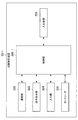
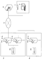
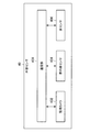
- FIG. 1 is an explanatory diagram showing the configuration of the monitoring system according to the first embodiment.
- the monitoring system according to the first embodiment includes a monitoring device 10, an automatic transaction device 20-1, a billing system host 22, and a dedicated network 24.
- the monitoring device 10 is a device that manages a failure occurrence state in the automatic transaction apparatus 20-1 by receiving failure occurrence information indicating the occurrence of a failure from an automatic transaction apparatus 20-1 described later. As shown in FIG. 1, the monitoring device 10 is installed, for example, in the monitoring center 4. As shown in FIG. 1, the monitoring center 4 can be installed at a location away from the branch 2 of the financial institution, for example.
- the monitoring apparatus 10 can communicate with the automatic transaction apparatus 20-1 through the dedicated network 24, for example.
- the monitoring device 10 can display a monitoring screen for monitoring a failure occurrence state of the plurality of automatic transaction devices 20-1 on the display. For example, a person in charge at the monitoring center 4 confirms the automatic transaction apparatus 20-1 in which a failure has occurred by checking the monitoring screen, and maintains the failure response of the automatic transaction apparatus 20-1. Can be instructed.
- the monitoring device 10 may be a mobile phone such as a PC (Personal Computer), a server, a tablet terminal, or a smartphone.
- PC Personal Computer
- server a server
- tablet terminal a tablet terminal
- smartphone a smartphone
- the automatic transaction apparatus 20-1 is a customer operation type terminal that executes a cash deposit / withdrawal transaction based on an operation by a customer of a financial institution, for example. As shown in FIG. 1, the automatic transaction apparatus 20-1 is installed, for example, in a branch 2 of a financial institution. However, the present invention is not limited to this example, and the automatic transaction apparatus 20-1 is installed in various facilities such as a convenience store, a station premises, a hotel, a hospital, an amusement park, a restaurant, an office building, an airport, or a boarding place. obtain.
- the automatic transaction apparatus 20-1 can communicate with an apparatus connected to the dedicated network 24.
- the automatic transaction apparatus 20-1 transmits processing requests for various transactions input by the customer to the account host 22.
- the account host 22 is a device that processes various money transactions (account transaction processing) such as deposits and withdrawals and transfers.
- the account host 22 manages customer information such as account information.
- the dedicated network 24 is a network used for transmitting and receiving information in the financial institution.
- the dedicated network 24 is configured by a dedicated line network such as an IP-VPN (Internet Protocol-Virtual Private Network).
- IP-VPN Internet Protocol-Virtual Private Network
- the monitoring screen displays the failure occurrence status of the plurality of automatic transaction apparatuses 20-1 in the financial institution.
- the number of maintenance personnel corresponding to the failure of the automatic transaction apparatus 20-1 is limited. Therefore, when a failure occurs in a plurality of automatic transaction apparatuses 20-1 at the same time, the person in charge of the monitoring center 4 can easily determine which automatic transaction apparatus 20-1 should be preferentially dealt with. It is desirable to be.
- the monitoring device 10 according to the first embodiment has been created by focusing on the above circumstances.
- the monitoring apparatus 10 according to the first embodiment displays the automatic transaction apparatus 20-1 to be preferentially dealt with on the monitoring screen in an easy-to-understand manner when a failure occurs in a plurality of automatic transaction apparatuses 20-1 at the same time. Is possible.
- the automatic transaction apparatus 20-1 includes a control unit 200-1, a communication unit 220, an operation display unit 222, an input unit 224, a card reader 226, and a deposit / withdrawal unit 228.
- Control unit 200-1 uses an automatic transaction using hardware such as a CPU (Central Processing Unit), a ROM (Read Only Memory), and a RAM (Random Access Memory) incorporated in the automatic transaction apparatus 20-1.
- the operation of the apparatus 20-1 is generally controlled.
- the control unit 200-1 controls the operation of other components such as the communication unit 220.
- control unit 200-1 detects the occurrence of a failure in the automatic transaction apparatus 20-1. Further, the control unit 200-1 generates failure occurrence information including the content of the detected failure and causes the monitoring device 10 to transmit the generated failure occurrence information to the communication unit 220.
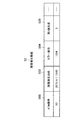
- the failure occurrence information 50 includes, for example, an ATM number 500, a failure occurrence date and time 502, and an error number 504.
- an identification number hereinafter also referred to as an ATM number
- the failure occurrence date / time 502 records the date and time when the failure occurred.
- the error number 504 records a failure identification number corresponding to the failure that has occurred.
- the failure identification number is a number that is determined in advance in association with, for example, the site where the failure has occurred, the type of failure, and the degree of failure.
- the communication unit 220 transmits and receives information to and from other devices via the dedicated network 24, for example.
- the communication unit 220 transmits various transaction processing requests input by the customer to the billing system host 22 in accordance with the control of the control unit 200-1.
- the operation display unit 222 includes a display unit that displays various display screens such as a transaction screen, and a function as an operation unit that detects an operation by a customer.
- the function as the display unit is realized by, for example, a CRT (Cathode Ray Tube) display device, a liquid crystal display (LCD) device, or an OLED (Organic Light Emitting Diode) device.
- the function as an operation part is implement
- the input unit 224 has a plurality of input keys for inputting characters, numbers, and the like. This input unit 224 is used, for example, for input of a personal identification number or transaction amount.
- the input unit 224 may be a pin pad, for example.
- the card reader 226 reads data recorded on, for example, a magnetic stripe or an IC (Integrated Circuit) chip with respect to a card inserted into a card insertion slot (not shown) provided in the automatic transaction apparatus 20-1.
- the deposit / withdrawal unit 228 is configured by a banknote deposit / withdrawal machine (not shown) or a coin deposit / withdrawal machine (not shown) provided in the automatic transaction apparatus 20-1, and performs deposit / withdrawal processing of banknotes or coins. For example, the deposit / withdrawal unit 228 counts the bills deposited by the customer into the bill insertion slot (not shown), and stores it in a safe (not shown) provided in the bill depositing / dispensing machine.
- the deposit / withdrawal unit 228 pays out banknotes or coins corresponding to the amount designated by the customer from the safe and counts them, and then inserts the bill insertion slot or coin insertion slot ( Eject from (not shown).
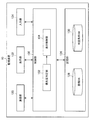
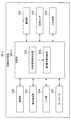
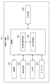
- FIG. 4 is a functional block diagram showing the configuration of the monitoring device 10 according to the first embodiment.
- the monitoring apparatus 10 includes a control unit 100, a communication unit 120, a display unit 122, an input unit 124, and a storage unit 126.
- the control unit 100 generally controls the operation of the monitoring device 10 using hardware such as a CPU 150 and a RAM 154 described later, which are built in the monitoring device 10.
- the control unit 100 includes a priority determination unit 102 and a display control unit 104.
- the priority determination unit 102 When the failure occurrence information is received from the plurality of automatic transaction apparatuses 20-1, the priority determination unit 102, based on information regarding each of the plurality of automatic transaction apparatuses 20-1 that is the transmission source of the failure occurrence information, The priority of failure handling of each of the plurality of automatic transaction apparatuses 20-1 is determined.
- the information regarding the automatic transaction apparatus 20-1 is, for example, attribute information of the automatic transaction apparatus 20-1 stored in the monitoring DB 128 described later.
- the attribute information of the automatic transaction apparatus 20-1 stored in the monitoring DB 128 for each of the plurality of automatic transaction apparatuses 20-1 that is the transmission source of the failure occurrence information will be described later. Based on whether or not the priority determination condition stored in the determination condition DB 130 is satisfied, the priority of the automatic transaction apparatus 20-1 is determined. More specifically, the attribute information of the automatic transaction apparatus 20-1 stored in the monitoring DB 128 is stored in the determination condition DB 130 for each of the plurality of automatic transaction apparatuses 20-1 that is the transmission source of the failure occurrence information.
- the priority determination unit 102 determines that the priority of the automatic transaction apparatus 20-1 is high. If the attribute information of the automatic transaction apparatus 20-1 does not correspond to any of the plurality of priority determination conditions stored in the determination condition DB 130, the priority determination unit 102 determines that the automatic transaction apparatus 20-1 It is determined that the priority of 20-1 is low (for example, the priority is “0”).
- the monitoring DB 128 is a database in which, for example, attribute information and failure occurrence status relating to all automatic transaction apparatuses 20-1 installed in financial institutions are recorded.
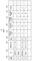
- a configuration example of the monitoring DB 128 will be described with reference to FIG.
- an ATM number 1280, an address 1282, a failure occurrence date 1284, an error number 1286, a distance 1288 with a neighboring ATM, an average number of transactions 1290 per day, a population in an installation area Density 1292, important store designation 1294, and priority 1296 are associated with each other.
- the ATM number of each automatic transaction apparatus 20-1 is recorded in the ATM number 1280.
- the address 1282 records the address of the facility where the automatic transaction apparatus 20-1 with the corresponding ATM number is installed. Further, the failure occurrence date / time 1284 records the failure occurrence date / time of the automatic transaction apparatus 20-1 having the corresponding ATM number. In addition, in the error number 1286, a failure identification number corresponding to a failure occurring in the automatic transaction apparatus 20-1 having the corresponding ATM number is recorded. The failure occurrence date / time 1284 and the error number 1286 are recorded with, for example, the failure occurrence date / time or failure identification number included in the failure occurrence information received from the automatic transaction apparatus 20-1 having the corresponding ATM number.
- the attribute information of the automatic transaction apparatus 20-1 of the corresponding ATM number is included in the distance 1288 with the neighboring ATM, the average number of transactions 1290 per day, the population density 1292 of the installation area, and the designation 1294 of the important store.
- the distance 1288 with the neighboring ATM records the distance between the installation facility (for example, branch 2) of the automatic transaction apparatus 20-1 having the corresponding ATM number and the installation facility of the adjacent automatic transaction apparatus 20-1.
- the average number of transactions per day 1290 records the average number of transactions per day of the automatic transaction apparatus 20-1 having the corresponding ATM number.
- the population density 1292 of the installation area records the population density of the installation area of the automatic transaction apparatus 20-1 having the corresponding ATM number.
- the important store designation 1294 records whether or not the branch 2 in which the automatic transaction apparatus 20-1 having the corresponding ATM number is installed is designated as an important store in the financial institution.
- the priority (corresponding to the failure) determined by the priority determination unit 102 with respect to the automatic transaction apparatus 20-1 having the corresponding ATM number is recorded.
- the determination condition DB 130 is a database in which a plurality of priority determination conditions, for example, predetermined by a financial institution are recorded.
- a configuration example of the determination condition DB 130 will be described with reference to FIG.
- the determination condition DB 130 for example, No 1300, determination condition 1302, and coefficient 1304 are associated with each other.
- No. 1300 an identification number assigned to each determination condition is recorded.
- the determination condition 1302 records the content of the determination condition of the corresponding identification number.
- the coefficient 1304 records a coefficient value that is determined in advance in association with the determination condition of the corresponding identification number.
- the determination condition 1302 and the coefficient 1304 basically register the determination condition or coefficient determined by the financial institution.
- the present invention is not limited to this example, and determination conditions or coefficients determined by the administrator of the monitoring center 4 may be registered.
- the priority determination unit 102 determines the priority of the automatic transaction apparatus 20-1 to be high.
- the priority determination unit 102 determines that the priority of the automatic transaction apparatus 20-1 is high. To do.
- the priority determination unit 102 includes, for each of the plurality of automatic transaction apparatuses 20-1 that is the transmission source of the failure occurrence information, the automatic determination among the priority determination conditions stored in the determination condition DB 130. It is also possible to determine a value corresponding to the sum of the coefficients registered in association with each of one or more determination conditions satisfied by the transaction apparatus 20-1 as the priority of the automatic transaction apparatus.
- the display control unit 104 for each of the plurality of automatic transaction apparatuses 20-1 that are the transmission source of the failure occurrence information, the automatic transaction apparatus 20-1 determines the failure information of the automatic transaction apparatus 20-1 by the priority determination unit 102. The higher the priority of the device 20-1, the more emphasized it is displayed on the monitoring screen. As an example, the display control unit 104 includes a plurality of failure occurrence information transmission sources such that the display position is higher in the failure information of the automatic transaction apparatus 20-1 having a higher priority determined by the priority determination unit 102. Each failure information of the automatic transaction apparatus 20-1 is displayed on the monitoring screen.
- FIG. 7 is an explanatory diagram showing a display example of the monitoring screen (monitoring screen 30).
- the failure information 320 includes, for example, an ATM number 300, an address 302, a failure occurrence date / time 304, an error number 306, a priority 308, and the like.
- the ATM number 300, the address 302, the failure occurrence date / time 304, the error number 306, and the priority 308 include, for example, the ATM number 1280, the address 1282, the failure occurrence date / time 1284, the error number 1286, or the priority in the monitoring DB 128.
- Each value recorded in 1296 is displayed.
- the display control unit 104 sorts the failure information 320 of each automatic transaction apparatus 20-1 and displays it on the monitoring screen 30 in descending order of the priority determined by the priority determination unit 102. .
- the person in charge of the monitoring center 4 determines which automatic transaction apparatus 20-1 should preferentially handle the failure. You can check at a glance if there is.
- information of the automatic transaction apparatus 20-1 in which no failure has occurred is also displayed on the monitoring screen 30 as in the failure information 320 d.
- An example is shown. However, the present invention is not limited to this example, and the monitoring screen 30 may display only the failure information 320 of the automatic transaction apparatus 20-1 in which a failure has occurred.
- the display control unit 104 determines the priority determined by the priority determination unit 102 with respect to the automatic transaction device 20-1a. It is also possible to update the display of the monitoring screen so that the failure information of the automatic transaction apparatus 20-1a is added (or changed) to the display position according to the above. For example, in the above case, the display control unit 104 first sorts the failure information of each automatic transaction apparatus 20-1 again in descending order of the priority determined by the priority determination unit 102. And the display control part 104 updates a display so that the failure information of each automatic transaction apparatus 20-1 may be displayed on the monitoring screen 30 in the order after re-sorting.
- FIG. 8 shows a monitor screen after the display update when the failure occurrence information is newly received from the automatic transaction apparatus 20-1a whose ATM number is “415” when the monitor screen 30a shown in FIG. 7 is displayed. It is explanatory drawing which showed the example (monitoring screen 30b).
- the priority determined by the priority determination unit 102 for the automatic transaction apparatus 20-1e having the ATM number “415” is “4”. Therefore, as shown in FIG.
- the failure information 320b of the automatic transaction apparatus 20-1b (priority is “5”) and the failure of the automatic transaction apparatus 20-1c (priority is “1”)
- the display control unit 104 updates the display of the monitoring screen 30 so that the failure information 320e of the automatic transaction apparatus 20-1e is additionally displayed between the information 320c.
- each time a failure occurs in another automatic transaction apparatus 20-1a the person in charge of the monitoring center 4 has a priority among the plurality of automatic transaction apparatuses 20-1 in which the failure has occurred. It is possible to sequentially confirm which is the higher automatic transaction apparatus 20-1.
- the communication unit 120 transmits and receives information to and from other devices via, for example, the dedicated network 24.
- the communication unit 120 receives failure occurrence information from each automatic transaction apparatus 20-1.
- the display unit 122 displays various display screens such as a monitoring screen under the control of the display control unit 104.
- the input unit 124 receives various input operations on the monitoring device 10 by the user. Further, the input unit 124 transmits the received operation information to the control unit 100.
- the storage unit 126 can store various data such as the monitoring DB 128 and the determination condition DB 130, for example.
- the configuration of the monitoring device 10 according to the first embodiment is not limited to the configuration described above.
- the monitoring DB 128 or the determination condition DB 130 may be stored in another device that can communicate with the monitoring device 10 instead of being stored in the storage unit 126.
- the display unit 122 or the input unit 124 may be included in another device that can communicate with the monitoring device 10 instead of being included in the monitoring device 10.
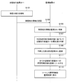
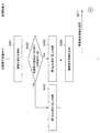
- FIG. 9 is a sequence diagram showing an operation according to the first embodiment.
- an example of operation when a failure occurs in an automatic transaction apparatus 20-1 will be described.
- the control unit 200-1 of the automatic transaction apparatus 20-1 detects the generated failure. (S101).
- control unit 200-1 generates failure occurrence information including the content of the failure detected in S101.
- communication part 220 transmits failure occurrence information to the monitoring apparatus 10 according to control of the control part 200-1 (S103).
- control unit 100 of the monitoring device 10 stores the content of the failure occurrence information received in S103 in the monitoring DB 128 in association with the corresponding automatic transaction device 20-1 (S105).
- the priority determination unit 102 determines whether or not the attribute information of the corresponding automatic transaction apparatus 20-1 stored in the monitoring DB 128 corresponds to the priority determination condition stored in the determination condition DB 130. Based on this, the priority of the corresponding automatic transaction apparatus 20-1 is determined (S107). Then, the priority determination unit 102 registers the determined priority in the monitoring DB 128 in association with the corresponding automatic transaction apparatus 20-1 (S109).
- the display control unit 104 generates the failure information of the corresponding automatic transaction apparatus 20-1 by extracting the information stored in the monitoring DB 128 in association with the corresponding automatic transaction apparatus 20-1. Then, the display control unit 104 sorts the failure information of each of the plurality of automatic transaction apparatuses 20-1 in which the failure has occurred in descending order of priority determined by the priority determination unit 102 (S111).
- the display control unit 104 displays the failure information of each of the sorted automatic transaction apparatuses 20-1 on the monitoring screen (S113).
- the monitoring apparatus 10 has the plurality of automatic transaction apparatuses 20-1 that are the transmission sources of failure occurrence information.
- the priority of each automatic transaction apparatus 20-1 is determined based on each attribute information and the determination condition of the priority stored in the determination condition DB 130, and the automatic transaction apparatus 20 having a high determined priority is determined.
- the failure information of each of the plurality of automatic transaction apparatuses 20-1 is displayed on the monitoring screen so that the display position is higher as the failure information of -1.
- the monitoring apparatus 10 can display the automatic transaction apparatus 20-1 to be preferentially dealt with on the monitoring screen in an easy-to-understand manner when a failure occurs in a plurality of automatic transaction apparatuses 20-1 at the same time. it can.
- the person in charge of the monitoring center 4 can easily determine which of the plurality of automatic transaction apparatuses 20-1 in which a failure has occurred should be prioritized.
- the priority determination conditions and the coefficients of the determination conditions stored in the determination condition DB 130 can be freely set by a financial institution, for example, or can be changed as appropriate. For this reason, for example, the financial institution can adopt the optimum judgment condition for the financial institution and the coefficient of each judgment condition in consideration of the number of transactions and the location conditions of the branch 2.
- Second Embodiment >> The first embodiment has been described above. Next, a second embodiment will be described. First, the background that led to the creation of the second embodiment will be described.
- the automatic transaction apparatus that the user is using or is waiting to use than the automatic transaction apparatus 20-1 in which the user does not exist when a failure occurs. It is desirable to prioritize the failure with 20-1.
- the failure information of each of the plurality of automatic transaction apparatuses 20-2 in which a failure has occurred is being used or used at the time of the failure. It is possible to display on the monitoring screen in the order in which the presence or absence of waiting users is reflected.
- FIG. 10 is a functional block diagram showing the configuration of the automatic transaction apparatus 20-2 according to the second embodiment.
- the automatic transaction apparatus 20-2 includes a control unit 200-2 instead of the control unit 200-1, as compared with the automatic transaction apparatus 20-1 according to the first embodiment.
- the automatic transaction apparatus 20-2 further includes a photographing unit 230 and a proximity sensor 232.
- a photographing unit 230 and a proximity sensor 232.
- control unit 200-2 further includes a user presence / absence determination unit 202 and a first priority determination unit 204 as compared with the control unit 200-1.
- the control unit 200-2 detects the content of the detected failure and the first priority determined by the first priority determination unit 204 described later.
- the first priority is an example of the priority in the present invention. Although the details will be described later, the first priority depends on, for example, whether or not there is a user using the automatic transaction apparatus 20-2, the number of users waiting to use the automatic transaction apparatus 20-2, and the like. The value to be determined.
- the failure occurrence information 52 further includes a first priority 520 compared to the failure occurrence information 50 according to the first embodiment shown in FIG. 3.
- the first priority 520 the value of the first priority determined by the first priority determination unit 204 is recorded.
- the user presence / absence determination unit 202 is, for example, a result of photographing by a photographing unit 230 described later or a proximity sensor 232 described later. Based on the detection result, it is determined whether or not there is a user in front of the automatic transaction apparatus 20-2. For example, the user presence / absence determination unit 202 searches for a person area in the photographed image taken by the photographing unit 230, and if a person area is detected, the user is displayed before the automatic transaction apparatus 20-2. Is determined to exist.
- the user presence / absence determination unit 202 determines that a user exists before the automatic transaction apparatus 20-2. Note that the user presence / absence determination unit 202 may determine that a user is present before the automatic transaction apparatus 20-2 when one or more of the two conditions are satisfied.
- a user presence / absence determination unit 202 can also determine that the user is present in front of the automatic transaction apparatus 20-2.
- the automatic transaction apparatus 20-2a when a failure occurs in the automatic transaction apparatus 20-2a, the user gives up using the automatic transaction apparatus 20-2a and is installed in the same facility (for example, the same branch 2). It is also envisaged to use another automated transaction apparatus 20-2b. Therefore, as a modification, when a failure occurs in the automatic transaction apparatus 20-2a, the automatic transaction apparatus 20-2a is operated by the photographing unit 230 of another automatic transaction apparatus 20-2b installed in the same facility. The photographing result, the detection result by the proximity sensor 232, and the like are received from the automatic transaction apparatus 20-2b, and the user presence / absence determination unit 202 (of the automatic transaction apparatus 20-2a) is based on the received information. It is also possible to determine whether or not exists.
- the user presence / absence determination unit 202 can also determine the number of users existing in front of the automatic transaction apparatus 20-2. For example, the user presence / absence determination unit 202 determines the number of different person areas detected from one captured image captured by the imaging unit 230 as the number of users existing in front of the automatic transaction apparatus 20-2. To do.
- the user presence / absence determination unit 202 can also determine the number of users based on a time interval at which a touch on the operation display unit 222 or the input unit 224 is detected. For example, the user presence / absence determination unit 202 is used every time the time interval from when the previous touch on the operation display unit 222 or the input unit 224 is detected to when the current touch is detected is longer than a predetermined time. The number of persons is counted up by “1”. According to this determination example, it is possible to count only when different users touch the operation display unit 222 (or the input unit 224) separately, for example, when one user hits repeatedly. Can be outside. Accordingly, it is possible to accurately determine the number of users who have touched the operation display unit 222 (or the input unit 224).
- the first priority determination unit 204 determines the first priority of the automatic transaction apparatus 20-2 based on the determination result by the user presence / absence determination unit 202.
- the first priority determination unit 204 determines that the first priority is high when the user presence / absence determination unit 202 determines that the user exists, and the user presence / absence determination unit 202 uses the first priority. When it is determined that there is no person, the first priority is determined to be low. As an example, the first priority determination unit 204 determines the first priority to be a predetermined value greater than “0” when the user presence / absence determination unit 202 determines that a user exists. If the user presence / absence determination unit 202 determines that there is no user, the first priority is determined to be “0”.
- the first priority determination unit 204 can also determine the first priority higher as the number of users determined by the user presence / absence determination unit 202 is larger. For example, the first priority determination unit 204 determines a value obtained by multiplying the number of users determined by the user presence determination unit 202 by a predetermined coefficient as the first priority. Or, for example, when the number of users is “1” or more and less than “5”, the value of the first priority is set for each range of the number of users such as “4” as the first priority. Is stored in the automatic transaction device 20-2, and the first priority determination unit 204 corresponds to the number of users determined by the user presence / absence determination unit 202. In addition, the value recorded in the first priority conversion table may be determined as the first priority.
- the imaging unit 230 captures an image in front of the automatic transaction apparatus 20-2 as a moving image, for example.
- the proximity sensor 232 is, for example, an infrared sensor or an ultrasonic sensor.
- the proximity sensor 232 detects the presence or absence of a person in front of the automatic transaction apparatus 20-2.
- monitoring device 10 Next, the configuration of the monitoring device 10 according to the second embodiment will be described.
- the components included in the monitoring device 10 according to the second embodiment are the same as those in the first embodiment shown in FIG. Below, only the component which has a function different from 1st Embodiment is demonstrated.
- the priority determination unit 102 relates to the attribute information of the automatic transaction apparatus 20-2 stored in the monitoring DB 128 for each of the plurality of automatic transaction apparatuses 20-2 that is the transmission source of the failure occurrence information. However, it is possible to determine the second priority of the automatic transaction apparatus 20-2 based on whether or not the priority determination condition stored in the determination condition DB 130 is satisfied.
- the priority determination unit 102 for each of the plurality of automatic transaction apparatuses 20-2 that is the transmission source of the failure occurrence information, the first priority included in the failure occurrence information received from the automatic transaction apparatus 20-2 Then, the (final) priority of the automatic transaction apparatus 20-2 can be determined by summing the second priority determined for the automatic transaction apparatus 20-2.
- the priority determination unit 102 receives the failure occurrence information received from the automatic transaction apparatus 20-2 for each of the plurality of automatic transaction apparatuses 20-2 that is the transmission source of the failure occurrence information. May be determined as the (final) priority of the automatic transaction apparatus 20-2. In the case of this modification, the priority determination unit 102 does not have to perform the above-described determination of the second priority for each of the plurality of automatic transaction apparatuses 20-2 that are the transmission sources of the failure occurrence information.
- the display control unit 104 transmits the failure occurrence information transmission source so that the failure information of the automatic transaction apparatus 20-2 having a higher priority determined by the priority determination unit 102 becomes higher in the display position.
- the failure information of each of the plurality of automatic transaction apparatuses 20-2 is displayed on the monitoring screen.
- a specific display method is the same as that in the first embodiment.
- the user presence / absence determining unit 202 of the automatic transaction apparatus 20-2 has a user in front of the automatic transaction apparatus 20-2 based on a result of photographing by the photographing unit 230 or a result of detection by the proximity sensor 232. It is determined whether or not (S203). When it is determined that there is a user before the automatic transaction apparatus 20-2 (S203: Yes), the first priority determination unit 204 sets the first priority to a high value (S205). Thereafter, the control unit 200-2 performs an operation of S209 described later.
- the first priority determination unit 204 sets the first priority to a low value (for example, “0”). Etc.) (S207).
- control unit 200-2 generates failure occurrence information including the content of the failure detected in S201 and the first priority set in S205 or S207 (S209). And the communication part 220 transmits failure occurrence information to the monitoring apparatus 10 according to control of the control part 200-2 (S211).
- the control unit 100 of the monitoring device 10 stores the content of the failure occurrence information received in S211 in the monitoring DB 128 in association with the corresponding automatic transaction device 20-2 ( S221).
- the priority determination unit 102 determines whether or not the attribute information of the corresponding automatic transaction apparatus 20-2 stored in the monitoring DB 128 corresponds to the priority determination condition stored in the determination condition DB 130. Based on this, the second priority of the corresponding automatic transaction apparatus 20-2 is determined (S223). Then, the priority determination unit 102 sums the first priority included in the failure occurrence information received in S211 and the second priority determined in S223, so that the corresponding automatic transaction apparatus 20-2 A (final) priority is determined (S225).
- the priority determination unit 102 registers the priority determined in S225 in the monitoring DB 128 in association with the corresponding automatic transaction apparatus 20-2 (S227).
- the monitoring device 10 has received the failure received from each of the plurality of automatic transaction devices 20-2 in which the failure has occurred.
- the priority of each automatic transaction apparatus 20-2 is determined in accordance with the first priority included in the occurrence information, and the display position is higher as the failure information of the automatic transaction apparatus 20-2 having a higher determined priority.
- the failure information of each of the plurality of automatic transaction apparatuses 20-2 is displayed on the monitoring screen.
- the monitoring device 10 displays the failure information of each of the plurality of automatic transaction devices 20-2 in the order in which the presence / absence of a user who is using or waiting to use the automatic transaction device 20-2 at the time of the failure is reflected. It can be displayed on the monitoring screen.
- the automatic transaction apparatus 20-2 where the user exists is prioritized over the automatic transaction apparatus 20-2 where the user does not exist when the failure occurs.
- the person in charge of the monitoring center 4 can decide to deal with the failure by referring to the monitoring screen.
- the automatic transaction apparatus 20-2 is being used or used based on the detection result by the components included in the automatic transaction apparatus 20-2 such as the photographing unit 230 and the proximity sensor 232.
- the automatic transaction apparatus 20-2 determines whether there is a waiting user.
- the automatic transaction apparatus 20-3 is being used or awaiting use based on the measurement result of the external sensor 40 provided outside the automatic transaction apparatus 20-3. It is possible for the automatic transaction apparatus 20-3 to determine the presence or absence of a person.
- FIG. 14 is an explanatory diagram showing the configuration of the monitoring system according to the third embodiment. As shown in FIG. 14, the monitoring system according to the third embodiment further includes an external sensor 40 as compared with the first embodiment shown in FIG. 1. The monitoring system includes an automatic transaction apparatus 20-3 instead of the automatic transaction apparatus 20-1.
- the external sensor 40 is various measuring devices provided in a facility such as the branch 2 where the automatic transaction apparatus 20-3 is installed.
- the external sensor 40 can communicate with, for example, all or some of the automatic transaction apparatuses 20-3 provided in the same facility by wired communication or wireless communication.
- the external sensor 40 includes, for example, a monitoring camera 402, an infrared sensor 404, a floor sensor 406, and a communication unit 408.
- the monitoring camera 402 captures an image such as a moving image of an area where the automatic transaction apparatus 20-3 is installed in the branch 2 (hereinafter also referred to as an automatic transaction apparatus 20-3 installation area).
- the monitoring camera 402 can be installed near the ceiling of the branch 2, for example.
- the infrared sensor 404 detects the presence or absence of a human in the area where the automatic transaction apparatus 20-3 is installed.
- the infrared sensor 404 can be installed near the ceiling of the branch 2, for example.
- the floor sensor 406 detects a change in weight in the installation area of the automatic transaction apparatus 20-3.
- the floor sensor 406 can be installed on the floor of the installation area of the automatic transaction apparatus 20-3, for example.
- the communication unit 408 uses, for example, all or a part of the automatic transaction apparatus 20-3 in the same branch 2 with the captured image captured by the monitoring camera 402, the detection result by the infrared sensor 404, and the detection result by the floor sensor 406. Send to.
- the configuration of the external sensor 40 is not limited to the configuration described above.
- the external sensor 40 may not include any one or two of the monitoring camera 402, the infrared sensor 404, or the floor sensor 406.
- the external sensor 40 may further include other types of measuring devices.
- FIG. 16 is a functional block diagram showing a configuration of an automatic transaction apparatus 20-3 according to the third embodiment.
- the automatic transaction apparatus 20-3 has a control unit 200-3 instead of the control unit 200-2, as compared with the automatic transaction apparatus 20-2 according to the second embodiment. Further, the automatic transaction apparatus 20-3 does not include the photographing unit 230 and the proximity sensor 232. In the following, only components having functions different from those of the second embodiment will be described.
- the user presence / absence determination unit 202 when a failure is detected in the automatic transaction apparatus 20-3, is taken by the monitoring camera 402 received from the external sensor 40, and is measured by the infrared sensor 404. Based on the result or the measurement result by the floor sensor 406, the presence / absence of a user who is using or waiting to use the automatic transaction apparatus 20-3 is determined.
- the user presence / absence determination unit 202 can also determine the number of users who are waiting to use the automatic transaction apparatus 20-3 based on the measurement result received from the external sensor 40.
- the first priority determination unit 204 determines the first priority of the automatic transaction apparatus 20-3 based on the determination result by the user presence / absence determination unit 202.
- the first priority determination unit 204 is provided for each automatic transaction apparatus 20-3 installed in a facility (for example, the same branch 2) where the automatic transaction apparatus 20-3 is installed.
- the higher the number of users waiting for use, the higher the first priority may be determined.
- the first priority determination unit 204 first determines the number of automatic transaction apparatuses 20-3 in the facility where the automatic transaction apparatus 20-3 is installed, and the inside of the facility determined by the user presence / absence determination unit 202.
- the number of users waiting to be used per automatic transaction apparatus 20-3 is calculated on the basis of the number of users waiting to be used.
- the first priority determination unit 204 determines a value corresponding to the calculated number of persons as the first priority (of the corresponding automatic transaction apparatus 20-3). According to this determination example, it is possible to determine the first priority of the automatic transaction apparatus 20-3 based on the same standard in all the facilities without being affected by the number of installed automatic transaction apparatuses 20-3 for each facility. it can.
- the configuration of the monitoring device 10 according to the third embodiment is the same as that of the second embodiment.
- the automatic transaction apparatus 20-3 according to the third embodiment is based on the measurement result by the external sensor 40 provided outside the automatic transaction apparatus 20-3. Thus, it is possible to determine the presence or absence of users who are using or waiting to use the automatic transaction apparatus 20-3 and the number of users waiting to use the automatic transaction apparatus 20-3. For this reason, the effect similar to 2nd Embodiment is acquired.
- the photographing unit 230 and the proximity sensor 232 may not operate normally depending on the content of the failure that has occurred in the automatic transaction apparatus 20-2.
- the automatic transaction apparatus 20-3 uses the measurement result by the external sensor 40, regardless of the failure which generate
- the monitoring device 10 includes a CPU 150, a ROM 152, a RAM 154, an internal bus 156, an input / output interface 158, an input device 160, a display device 162, an HDD (Hard Disk Drive) 164, and a network interface 166. .
- the CPU 150 functions as an arithmetic processing device and a control device, and controls the overall operation in the monitoring device 10 according to various programs. Further, the CPU 150 realizes the function of the control unit 100.
- the CPU 150 is configured by a processor such as a microprocessor.
- the ROM 152 stores programs and calculation parameters used by the CPU 150.
- RAM154 temporarily stores programs used in the execution of the CPU 150, parameters that change as appropriate during the execution, and the like.
- the internal bus 156 is composed of a CPU bus and the like.
- the internal bus 156 connects the CPU 150, the ROM 152, and the RAM 154 to each other.
- the input / output interface 158 connects the input device 160, the display device 162, the HDD 164, and the network interface 166 to the internal bus 156.
- the HDD 164 exchanges data with the RAM 154 or the like via the input / output interface 158 and the internal bus 156.
- the input device 160 includes, for example, input means for a user to input information such as a keyboard, mouse, button, microphone, and switch, and an input control circuit that generates an input signal based on the input by the user and outputs the input signal to the CPU 150. It is configured.
- the input device 160 functions as the input unit 124.
- the display device 162 includes, for example, a display device such as a liquid crystal display (LCD) device, an OLED device, and a lamp.
- the display device 162 functions as the display unit 122.
- the HDD 164 is a data storage device.
- the HDD 164 includes, for example, a storage medium, a recording device that records data on the storage medium, a reading device that reads data from the storage medium, and a deletion device that deletes data recorded on the storage medium.
- the HDD 164 stores programs executed by the CPU 150 and various data.
- the HDD 164 functions as the storage unit 126.
- the network interface 166 is a communication interface configured by a communication device for connecting to the dedicated network 24, for example. This network interface 166 functions as the communication unit 120.
- the network interface 166 may be a wireless LAN compatible communication device, an LTE (Long Term Evolution) compatible communication device, or a wire communication device that performs wired communication.
- the monitoring apparatus 10 may make the determination.
- the monitoring device 10 receives, for example, the determination result of the presence / absence of the user and the number of users waiting for use determined from the automatic transaction device 20 (the user presence / absence determination unit 202) from the automatic transaction device 20, Then, the monitoring device 10 may determine the first priority based on the received determination result.
- the automatic transaction apparatus 20 determines whether or not there are users who are using or waiting to use the automatic transaction apparatus 20 and the number of users who are waiting for use.
- the monitoring apparatus 10 may determine. For example, the monitoring device 10 receives a photographed image by the photographing unit 230, a detection result by the proximity sensor 232, a measurement result by the external sensor 40, or the like from the automatic transaction device 20, and the monitoring device 10 adds the received information to the received information. Based on this, the presence or absence of users who are using or waiting to use the automatic transaction apparatus 20 and the number of users who are waiting to use the automatic transaction apparatus 20 may be determined.
Landscapes
- Business, Economics & Management (AREA)
- Engineering & Computer Science (AREA)
- General Physics & Mathematics (AREA)
- Accounting & Taxation (AREA)
- Physics & Mathematics (AREA)
- Theoretical Computer Science (AREA)
- Finance (AREA)
- General Business, Economics & Management (AREA)
- Strategic Management (AREA)
- Marketing (AREA)
- Economics (AREA)
- Technology Law (AREA)
- Development Economics (AREA)
- Entrepreneurship & Innovation (AREA)
- Human Resources & Organizations (AREA)
- Operations Research (AREA)
- Quality & Reliability (AREA)
- Tourism & Hospitality (AREA)
- Financial Or Insurance-Related Operations Such As Payment And Settlement (AREA)
Abstract
【課題】複数の自動取引装置において障害が発生した場合に、優先して対応すべき自動取引装置を分かりやすく表示させることが可能な、監視装置、及び監視システムを提供する。 【解決手段】自動取引装置の障害の発生を示す障害発生情報を複数の自動取引装置から受信する通信部と、前記複数の自動取引装置の各々に関する情報に基づいて判定された優先度が高い自動取引装置ほど表示位置が上になるように、前記複数の自動取引装置の各々の障害を示す表示を監視画面に表示させる表示制御部と、を備える、監視装置。
Description
本発明は、監視装置、及び監視システムに関する。
昨今、金融機関のATM(Automated teller machine)に代表される自動取引装置は、銀行、駅構内およびコンビニエンスストアなど、多様な場所に設置されている。
このような自動取引装置の稼働状況を外部の施設から監視するための技術が各種提案されている。例えば、特許文献1には、自動取引装置で障害が発生した際に、監視サーバが、障害に関する情報を自動取引装置から取得する技術が記載されている。
ところで、複数の自動取引装置において障害が発生した場合には、より優先度の高い自動取引装置を優先して障害対応することが望まれる。
しかしながら、特許文献1に記載の技術では、障害が発生した自動取引装置の情報を、障害が発生した順に表示画面に表示させる。このため、特許文献1に記載の技術では、同時に複数の自動取引装置において障害が発生した場合には、優先して対応すべき自動取引装置がいずれであるかをユーザが識別し難かった。
そこで、複数の自動取引装置において障害が発生した場合に、優先して対応すべき自動取引装置を分かりやすく表示させることが可能な監視装置、及び監視システムが望まれた。
本発明のある観点によれば、自動取引装置の障害の発生を示す障害発生情報を複数の自動取引装置から受信する通信部と、前記複数の自動取引装置の各々に関する情報に基づいて判定された優先度が高い自動取引装置ほど表示位置が上になるように、前記複数の自動取引装置の各々の障害を示す表示を監視画面に表示させる表示制御部と、を備える、監視装置が提供される。
前記監視装置は、前記複数の自動取引装置の各々に関する情報に基づいて前記複数の自動取引装置の各々の障害対応の優先度を判定する優先度判定部をさらに備えてもよい。
前記複数の自動取引装置の各々に関する情報は、前記複数の自動取引装置の各々の属性情報を含み、前記監視装置は、前記複数の自動取引装置の各々に対応づけて属性情報を記憶し、かつ、予め定められている、優先度の複数の判定条件を記憶する記憶部をさらに備え、前記優先度判定部は、前記複数の自動取引装置の各々に関して、前記記憶部に記憶されている当該自動取引装置の属性情報が前記優先度の複数の判定条件に該当するか否かに基づいて前記複数の自動取引装置の各々の優先度を判定してもよい。
前記複数の自動取引装置の各々に関して、前記記憶部に記憶されている当該自動取引装置の属性情報が前記優先度の複数の判定条件のうち一以上に該当する場合には、前記優先度判定部は、当該自動取引装置の優先度が高いと判定してもよい。
前記自動取引装置の属性情報は、近隣の自動取引装置との距離、所定の期間における自動取引装置の取引件数、または、自動取引装置の設置地域の人口密度を含んでもよい。
前記記憶部は、さらに、前記優先度の複数の判定条件の各々と対応づけて係数を記憶し、前記優先度判定部は、前記複数の自動取引装置の各々に関して、前記優先度の複数の判定条件のうち当該自動取引装置が満たす一以上の判定条件に対応付けられた係数の合計に応じた値を当該自動取引装置の優先度に設定してもよい。
前記複数の自動取引装置の各々に関する情報は、前記複数の自動取引装置の各々により判断された当該自動取引装置の優先度を含み、前記通信部は、前記複数の自動取引装置の各々による当該自動取引装置の優先度を前記複数の自動取引装置の各々からさらに受信し、前記表示制御部は、受信された優先度が高い自動取引装置ほど表示位置が上になるように、前記複数の自動取引装置の各々の障害を示す表示を前記監視画面に表示させてもよい。
前記複数の自動取引装置の各々に関する情報は、前記複数の自動取引装置の各々の前に利用者が存在するか否かを示す利用者の有無情報を含み、前記通信部は、さらに、前記利用者の有無情報を前記複数の自動取引装置の各々から受信し、前記優先度判定部は、前記複数の自動取引装置の各々に関して、当該自動取引装置から受信された前記利用者の有無情報が当該自動取引装置の前に利用者が存在することを示す場合には当該自動取引装置の優先度が高いと判定し、前記利用者の有無情報が当該自動取引装置の前に利用者が存在しないことを示す場合には当該自動取引装置の優先度が低いと判定してもよい。
前記複数の自動取引装置の各々の障害を示す表示は、前記複数の自動取引装置の各々の識別情報、および、障害識別番号を含んでもよい。
前記監視装置は、前記監視画面を表示する表示部をさらに備えてもよい。
また、本発明の別の観点によれば、複数の自動取引装置、および、監視装置を有し、前記監視装置は、前記自動取引装置の障害の発生を示す障害発生情報を前記複数の自動取引装置から受信する通信部と、前記複数の自動取引装置の各々に関する情報に基づいて判定された優先度が高い自動取引装置ほど表示位置が上になるように、前記複数の自動取引装置の各々の障害を示す表示を監視画面に表示させる表示制御部と、を備える、監視システムが提供される。
以上説明したように本発明によれば、複数の自動取引装置において障害が発生した場合に、優先して対応すべき自動取引装置を分かりやすく表示させることができる。
以下に添付図面を参照しながら、本発明の好適な実施の形態について詳細に説明する。なお、本明細書及び図面において、実質的に同一の機能構成を有する構成要素については、同一の符号を付することにより重複説明を省略する。
また、本明細書及び図面において、実質的に同一の機能構成を有する複数の構成要素を、同一の符号の後に異なるアルファベットを付して区別する場合もある。例えば、実質的に同一の機能構成を有する複数の構成を、必要に応じて自動取引装置20‐1aおよび自動取引装置20‐1bのように区別する。ただし、実質的に同一の機能構成を有する複数の構成要素の各々を特に区別する必要がない場合、同一符号のみを付する。例えば、自動取引装置20‐1aおよび自動取引装置20‐1bを特に区別する必要が無い場合には、単に自動取引装置20‐1と称する。
また、以下に示す項目順序に従って当該「発明を実施するための形態」を説明する。
1.第1の実施形態
2.第2の実施形態
3.第3の実施形態
4.ハードウェア構成
5.変形例
1.第1の実施形態
2.第2の実施形態
3.第3の実施形態
4.ハードウェア構成
5.変形例
なお、本明細書及び図面において、第1の実施形態による自動取引装置20‐1、第2の実施形態による自動取引装置20‐2、および第3の実施形態による自動取引装置20‐3を特に区別する必要がない場合には、総称的に自動取引装置20と記載する場合がある。
<<1.第1の実施形態>>
本発明は、一例として「1.第1の実施形態」~「3.第3の実施形態」において詳細に説明するように、多様な形態で実施され得る。まず、第1の実施形態について説明する。
本発明は、一例として「1.第1の実施形態」~「3.第3の実施形態」において詳細に説明するように、多様な形態で実施され得る。まず、第1の実施形態について説明する。
<1-1.監視システムの構成>
図1は、第1の実施形態による監視システムの構成を示した説明図である。図1に示したように、第1の実施形態による監視システムは、監視装置10、自動取引装置20‐1、勘定系ホスト22、および専用網24を含む。
図1は、第1の実施形態による監視システムの構成を示した説明図である。図1に示したように、第1の実施形態による監視システムは、監視装置10、自動取引装置20‐1、勘定系ホスト22、および専用網24を含む。
[1-1-1.監視装置10]
監視装置10は、後述する自動取引装置20‐1から障害の発生を示す障害発生情報を受信することにより、自動取引装置20‐1における障害の発生状況を管理する装置である。この監視装置10は、図1に示したように、例えば監視センタ4内に設置される。なお、図1に示したように、監視センタ4は、例えば、金融機関の支店2から離れた場所に設置され得る。
監視装置10は、後述する自動取引装置20‐1から障害の発生を示す障害発生情報を受信することにより、自動取引装置20‐1における障害の発生状況を管理する装置である。この監視装置10は、図1に示したように、例えば監視センタ4内に設置される。なお、図1に示したように、監視センタ4は、例えば、金融機関の支店2から離れた場所に設置され得る。
この監視装置10は、例えば専用網24を介して、自動取引装置20‐1と通信することが可能である。
また、監視装置10は、複数の自動取引装置20‐1の障害の発生状況を監視するための監視画面をディスプレイに表示させることが可能である。例えば、監視センタ4に勤務する担当者は、監視画面を確認することにより、障害が発生している自動取引装置20‐1を確認し、そして、当該自動取引装置20‐1の障害対応を保守員に指示することが可能である。
なお、監視装置10は、例えばPC(Personal Computer)、サーバ、タブレット端末、または、スマートフォンなどの携帯電話であってもよい。
[1-1-2.自動取引装置20‐1]
自動取引装置20‐1は、例えば金融機関の顧客による操作に基づいて現金の入出金の取引を実行する顧客操作型端末である。この自動取引装置20‐1は、図1に示したように、例えば金融機関の支店2内に設置される。但し、かかる例に限定されず、自動取引装置20‐1は、コンビニエンスストア、駅構内、ホテル、病院、アミューズメントパーク、飲食店、オフィスビルディング、空港、または、乗船場などの多様な施設に設置され得る。
自動取引装置20‐1は、例えば金融機関の顧客による操作に基づいて現金の入出金の取引を実行する顧客操作型端末である。この自動取引装置20‐1は、図1に示したように、例えば金融機関の支店2内に設置される。但し、かかる例に限定されず、自動取引装置20‐1は、コンビニエンスストア、駅構内、ホテル、病院、アミューズメントパーク、飲食店、オフィスビルディング、空港、または、乗船場などの多様な施設に設置され得る。
また、自動取引装置20‐1は、専用網24に接続された装置との間で通信を行うことが可能である。例えば、自動取引装置20‐1は、顧客により入力された各種取引の処理要求を勘定系ホスト22へ送信する。
[1-1-3.勘定系ホスト22]
勘定系ホスト22は、入出金や振込などの各種の金銭取引(勘定の取引処理)を処理する装置である。また、勘定系ホスト22は、例えば口座情報などの顧客情報を管理する。
勘定系ホスト22は、入出金や振込などの各種の金銭取引(勘定の取引処理)を処理する装置である。また、勘定系ホスト22は、例えば口座情報などの顧客情報を管理する。
[1-1-4.専用網24]
専用網24は、金融機関内の情報の送受信に利用されるネットワークである。専用網24は、例えばIP-VPN(Internet Protocol-Virtual Private Network)などの専用回線網により構成される。
専用網24は、金融機関内の情報の送受信に利用されるネットワークである。専用網24は、例えばIP-VPN(Internet Protocol-Virtual Private Network)などの専用回線網により構成される。
[1-1-5.課題の整理]
以上、第1の実施形態による監視システムの構成について説明した。上述したように、監視画面では、金融機関における複数の自動取引装置20‐1の障害の発生状況が表示される。ところで、通常、自動取引装置20‐1の障害を対応する保守員の人数は限られている。このため、同時に複数の自動取引装置20‐1において障害が発生した場合には、監視センタ4の担当者は、いずれの自動取引装置20‐1を優先して対応すべきかが容易に判断可能であることが望ましい。
以上、第1の実施形態による監視システムの構成について説明した。上述したように、監視画面では、金融機関における複数の自動取引装置20‐1の障害の発生状況が表示される。ところで、通常、自動取引装置20‐1の障害を対応する保守員の人数は限られている。このため、同時に複数の自動取引装置20‐1において障害が発生した場合には、監視センタ4の担当者は、いずれの自動取引装置20‐1を優先して対応すべきかが容易に判断可能であることが望ましい。
そこで、上記事情を一着眼点にして、第1の実施形態による監視装置10を創作するに至った。第1の実施形態による監視装置10は、同時に複数の自動取引装置20‐1において障害が発生した場合に、優先して障害対応すべき自動取引装置20‐1を分かりやすく監視画面に表示させることが可能である。
<1-2.構成>
[1-2-1.自動取引装置20‐1]
次に、第1の実施形態による構成について説明する。まず、第1の実施形態による自動取引装置20‐1の構成について、図2を参照して説明する。図2に示したように、自動取引装置20‐1は、制御部200‐1、通信部220、操作表示部222、入力部224、カードリーダ226、および、入出金部228を有する。
[1-2-1.自動取引装置20‐1]
次に、第1の実施形態による構成について説明する。まず、第1の実施形態による自動取引装置20‐1の構成について、図2を参照して説明する。図2に示したように、自動取引装置20‐1は、制御部200‐1、通信部220、操作表示部222、入力部224、カードリーダ226、および、入出金部228を有する。
(1-2-1-1.制御部200‐1)
制御部200‐1は、自動取引装置20‐1に内蔵される、例えばCPU(Central Processing Unit)、ROM(Read Only Memery)、およびRAM(Random Access Memery)などのハードウェアを用いて、自動取引装置20‐1の動作を全般的に制御する。例えば、制御部200‐1は、通信部220などの他の構成要素の動作を制御する。
制御部200‐1は、自動取引装置20‐1に内蔵される、例えばCPU(Central Processing Unit)、ROM(Read Only Memery)、およびRAM(Random Access Memery)などのハードウェアを用いて、自動取引装置20‐1の動作を全般的に制御する。例えば、制御部200‐1は、通信部220などの他の構成要素の動作を制御する。
また、制御部200‐1は、自動取引装置20‐1における障害の発生を検知する。さらに、制御部200‐1は、検知した障害の内容を含む障害発生情報を生成し、そして、生成した障害発生情報を監視装置10へ通信部220に送信させる。
‐障害発生情報
ここで、図3を参照して、第1の実施形態による障害発生情報の構成例(障害発生情報50)について説明する。図3に示したように、障害発生情報50は、例えばATM番号500、障害発生日時502、および、エラー番号504を含む。ここで、ATM番号500には、該当の自動取引装置20‐1に予め割り当てられている、自動取引装置20‐1の識別番号(以下、ATM番号とも称する)が記録される。また、障害発生日時502には、障害が発生した日時が記録される。また、エラー番号504には、発生した障害に対応する障害識別番号が記録される。なお、障害識別番号は、例えば障害が発生している部位、障害の種類、および障害の程度などに対応付けて予め定められている番号である。
ここで、図3を参照して、第1の実施形態による障害発生情報の構成例(障害発生情報50)について説明する。図3に示したように、障害発生情報50は、例えばATM番号500、障害発生日時502、および、エラー番号504を含む。ここで、ATM番号500には、該当の自動取引装置20‐1に予め割り当てられている、自動取引装置20‐1の識別番号(以下、ATM番号とも称する)が記録される。また、障害発生日時502には、障害が発生した日時が記録される。また、エラー番号504には、発生した障害に対応する障害識別番号が記録される。なお、障害識別番号は、例えば障害が発生している部位、障害の種類、および障害の程度などに対応付けて予め定められている番号である。
(1-2-1-2.通信部220)
通信部220は、例えば専用網24を介して、他の装置との間で情報の送受信を行う。例えば、通信部220は、制御部200‐1の制御に従って、顧客により入力された各種取引の処理要求を勘定系ホスト22へ送信する。
通信部220は、例えば専用網24を介して、他の装置との間で情報の送受信を行う。例えば、通信部220は、制御部200‐1の制御に従って、顧客により入力された各種取引の処理要求を勘定系ホスト22へ送信する。
(1-2-1-3.操作表示部222)
操作表示部222は、取引画面などの各種表示画面を表示する表示部、および顧客による操作を検出する操作部としての機能を包含する。表示部としての機能は、例えば、CRT(Cathode Ray Tube)ディスプレイ装置、液晶ディスプレイ(LCD:Liquid Crystal Display)装置、OLED(Organic Light Emitting Diode)装置により実現される。また、操作部としての機能は例えばタッチパネルにより実現される。
操作表示部222は、取引画面などの各種表示画面を表示する表示部、および顧客による操作を検出する操作部としての機能を包含する。表示部としての機能は、例えば、CRT(Cathode Ray Tube)ディスプレイ装置、液晶ディスプレイ(LCD:Liquid Crystal Display)装置、OLED(Organic Light Emitting Diode)装置により実現される。また、操作部としての機能は例えばタッチパネルにより実現される。
(1-2-1-4.入力部224)
入力部224は、文字や数字などを入力するための入力キーを複数有する。この入力部224は、例えば暗証番号の入力や、取引金額の入力などに用いられる。入力部224は、例えばピンパッドであってもよい。
入力部224は、文字や数字などを入力するための入力キーを複数有する。この入力部224は、例えば暗証番号の入力や、取引金額の入力などに用いられる。入力部224は、例えばピンパッドであってもよい。
(1-2-1-5.カードリーダ226)
カードリーダ226は、自動取引装置20‐1に設けられたカード挿入口(図示省略)に挿入されたカードに関して、例えば磁気ストライプやIC(Integrated Circuit)チップなどに記録されたデータの読み取りを行う。
カードリーダ226は、自動取引装置20‐1に設けられたカード挿入口(図示省略)に挿入されたカードに関して、例えば磁気ストライプやIC(Integrated Circuit)チップなどに記録されたデータの読み取りを行う。
(1-2-1-6.入出金部228)
入出金部228は、自動取引装置20‐1内に設けられた紙幣入出金機(図示省略)または硬貨入出金機(図示省略)により構成され、紙幣または硬貨の入出金処理を行う。例えば、入出金部228は、顧客により紙幣挿入口(図示省略)に入金された紙幣を計数し、そして、紙幣入出金機内に設けられた金庫(図示省略)に収納する。また、入出金部228は、例えば「支払取引」が実行される場合には、顧客により指定される金額に相当する紙幣または硬貨をそれぞれ金庫から繰り出して計数し、紙幣挿入口または硬貨挿入口(図示省略)から排出する。
入出金部228は、自動取引装置20‐1内に設けられた紙幣入出金機(図示省略)または硬貨入出金機(図示省略)により構成され、紙幣または硬貨の入出金処理を行う。例えば、入出金部228は、顧客により紙幣挿入口(図示省略)に入金された紙幣を計数し、そして、紙幣入出金機内に設けられた金庫(図示省略)に収納する。また、入出金部228は、例えば「支払取引」が実行される場合には、顧客により指定される金額に相当する紙幣または硬貨をそれぞれ金庫から繰り出して計数し、紙幣挿入口または硬貨挿入口(図示省略)から排出する。
[1-2-2.監視装置10]
次に、第1の実施形態による監視装置10の構成について説明する。図4は、第1の実施形態による監視装置10の構成を示した機能ブロック図である。図4に示したように、監視装置10は、制御部100、通信部120、表示部122、入力部124、および、記憶部126を有する。
次に、第1の実施形態による監視装置10の構成について説明する。図4は、第1の実施形態による監視装置10の構成を示した機能ブロック図である。図4に示したように、監視装置10は、制御部100、通信部120、表示部122、入力部124、および、記憶部126を有する。
(1-2-2-1.制御部100)
制御部100は、監視装置10に内蔵される、後述するCPU150およびRAM154などのハードウェアを用いて、監視装置10の動作を全般的に制御する。また、図4に示したように、制御部100は、優先度判定部102、および表示制御部104を有する。
制御部100は、監視装置10に内蔵される、後述するCPU150およびRAM154などのハードウェアを用いて、監視装置10の動作を全般的に制御する。また、図4に示したように、制御部100は、優先度判定部102、および表示制御部104を有する。
(1-2-2-2.優先度判定部102)
優先度判定部102は、複数の自動取引装置20‐1から障害発生情報が受信された場合に、障害発生情報の送信元である複数の自動取引装置20‐1の各々に関する情報に基づいて、複数の自動取引装置20‐1の各々の障害対応の優先度を判定する。ここで、自動取引装置20‐1に関する情報は、例えば、後述する監視DB128に格納されている自動取引装置20‐1の属性情報である。
優先度判定部102は、複数の自動取引装置20‐1から障害発生情報が受信された場合に、障害発生情報の送信元である複数の自動取引装置20‐1の各々に関する情報に基づいて、複数の自動取引装置20‐1の各々の障害対応の優先度を判定する。ここで、自動取引装置20‐1に関する情報は、例えば、後述する監視DB128に格納されている自動取引装置20‐1の属性情報である。
‐判定例1
例えば、優先度判定部102は、障害発生情報の送信元である複数の自動取引装置20‐1の各々に関して、監視DB128に格納されている当該自動取引装置20‐1の属性情報が、後述する判定条件DB130に格納されている優先度の判定条件に該当するか否かに基づいて、当該自動取引装置20‐1の優先度を判定する。より具体的には、障害発生情報の送信元である複数の自動取引装置20‐1の各々に関して、監視DB128に格納されている当該自動取引装置20‐1の属性情報が、判定条件DB130に格納されている優先度の判定条件のうち一以上に該当する場合には、優先度判定部102は、当該自動取引装置20‐1の優先度が高いと判定する。また、当該自動取引装置20‐1の属性情報が、判定条件DB130に格納されている優先度の複数の判定条件のいずれにも該当しない場合には、優先度判定部102は、当該自動取引装置20‐1の優先度が低い(例えば優先度が「0」)と判定する。
例えば、優先度判定部102は、障害発生情報の送信元である複数の自動取引装置20‐1の各々に関して、監視DB128に格納されている当該自動取引装置20‐1の属性情報が、後述する判定条件DB130に格納されている優先度の判定条件に該当するか否かに基づいて、当該自動取引装置20‐1の優先度を判定する。より具体的には、障害発生情報の送信元である複数の自動取引装置20‐1の各々に関して、監視DB128に格納されている当該自動取引装置20‐1の属性情報が、判定条件DB130に格納されている優先度の判定条件のうち一以上に該当する場合には、優先度判定部102は、当該自動取引装置20‐1の優先度が高いと判定する。また、当該自動取引装置20‐1の属性情報が、判定条件DB130に格納されている優先度の複数の判定条件のいずれにも該当しない場合には、優先度判定部102は、当該自動取引装置20‐1の優先度が低い(例えば優先度が「0」)と判定する。
‐‐監視DB128
監視DB128は、例えば金融機関に設置されている全ての自動取引装置20‐1に関する属性情報や障害の発生状況が記録されるデータベースである。ここで、図5を参照して、監視DB128の構成例について説明する。図5に示したように、監視DB128では、例えば、ATM番号1280、住所1282、障害発生日時1284、エラー番号1286、近隣のATMとの距離1288、一日当たりの平均取引数1290、設置地域の人口密度1292、重要店舗の指定1294、および優先度1296が対応づけられている。ここで、ATM番号1280には、各自動取引装置20‐1のATM番号が記録される。また、住所1282には、該当のATM番号の自動取引装置20‐1が設置されている施設の住所が記録される。また、障害発生日時1284には、該当のATM番号の自動取引装置20‐1の障害発生日時が記録される。また、エラー番号1286には、該当のATM番号の自動取引装置20‐1で発生している障害に対応する障害識別番号が記録される。なお、障害発生日時1284およびエラー番号1286には、例えば、該当のATM番号の自動取引装置20‐1から受信された障害発生情報に含まれる障害発生日時または障害識別番号がそれぞれ記録される。
監視DB128は、例えば金融機関に設置されている全ての自動取引装置20‐1に関する属性情報や障害の発生状況が記録されるデータベースである。ここで、図5を参照して、監視DB128の構成例について説明する。図5に示したように、監視DB128では、例えば、ATM番号1280、住所1282、障害発生日時1284、エラー番号1286、近隣のATMとの距離1288、一日当たりの平均取引数1290、設置地域の人口密度1292、重要店舗の指定1294、および優先度1296が対応づけられている。ここで、ATM番号1280には、各自動取引装置20‐1のATM番号が記録される。また、住所1282には、該当のATM番号の自動取引装置20‐1が設置されている施設の住所が記録される。また、障害発生日時1284には、該当のATM番号の自動取引装置20‐1の障害発生日時が記録される。また、エラー番号1286には、該当のATM番号の自動取引装置20‐1で発生している障害に対応する障害識別番号が記録される。なお、障害発生日時1284およびエラー番号1286には、例えば、該当のATM番号の自動取引装置20‐1から受信された障害発生情報に含まれる障害発生日時または障害識別番号がそれぞれ記録される。
また、近隣のATMとの距離1288、一日当たりの平均取引数1290、設置地域の人口密度1292、および、重要店舗の指定1294には、該当のATM番号の自動取引装置20‐1の属性情報が記録される。例えば、近隣のATMとの距離1288には、該当のATM番号の自動取引装置20‐1の設置施設(例えば支店2)と近隣の自動取引装置20‐1の設置施設との距離が記録される。また、一日当たりの平均取引数1290には、該当のATM番号の自動取引装置20‐1の一日当たりの平均取引件数が記録される。また、設置地域の人口密度1292には、該当のATM番号の自動取引装置20‐1の設置地域の人口密度が記録される。また、重要店舗の指定1294には、該当のATM番号の自動取引装置20‐1が設置されている支店2が金融機関において重要店舗に指定されているか否かが記録される。
また、優先度1296には、該当のATM番号の自動取引装置20‐1に関して優先度判定部102により判定された(障害対応の)優先度が記録される。
‐‐判定条件DB130
また、判定条件DB130は、例えば金融機関により予め定められている複数の、優先度の判定条件が記録されるデータベースである。ここで、図6を参照して、判定条件DB130の構成例について説明する。図6に示したように、判定条件DB130では、例えば、No1300、判定条件1302、および係数1304が対応づけられている。ここで、No1300には、各判定条件に割り当てられた識別番号が記録される。また、判定条件1302には、該当の識別番号の判定条件の内容が記録される。また、係数1304には、該当の識別番号の判定条件に対応付けて予め定められている係数の値が記録される。なお、判定条件1302、および、係数1304には、基本的に、金融機関により定められた判定条件または係数がそれぞれ登録される。但し、かかる例に限定されず、監視センタ4の管理者により定められた判定条件または係数がそれぞれ登録されてもよい。
また、判定条件DB130は、例えば金融機関により予め定められている複数の、優先度の判定条件が記録されるデータベースである。ここで、図6を参照して、判定条件DB130の構成例について説明する。図6に示したように、判定条件DB130では、例えば、No1300、判定条件1302、および係数1304が対応づけられている。ここで、No1300には、各判定条件に割り当てられた識別番号が記録される。また、判定条件1302には、該当の識別番号の判定条件の内容が記録される。また、係数1304には、該当の識別番号の判定条件に対応付けて予め定められている係数の値が記録される。なお、判定条件1302、および、係数1304には、基本的に、金融機関により定められた判定条件または係数がそれぞれ登録される。但し、かかる例に限定されず、監視センタ4の管理者により定められた判定条件または係数がそれぞれ登録されてもよい。
図6に示した例のように、障害発生情報の送信元である複数の自動取引装置20‐1の各々に関して、例えば、当該自動取引装置20‐1の設置施設と近隣の自動取引装置20‐1の設置施設との距離が所定の距離よりも大きい場合には、優先度判定部102は、当該自動取引装置20‐1の優先度を高く判定する。同様に、当該自動取引装置20‐1の一日当たりの平均取引数が所定の件数以上である場合、当該自動取引装置20‐1の設置地域の人口密度が所定の人口密度以上である場合、または、当該自動取引装置20‐1が設置されている支店2が金融機関において重要店舗に指定されている場合には、優先度判定部102は、当該自動取引装置20‐1の優先度を高く判定する。
‐判定例2
なお、変形例として、優先度判定部102は、障害発生情報の送信元である複数の自動取引装置20‐1の各々に関して、判定条件DB130に格納されている優先度の判定条件のうち当該自動取引装置20‐1が満たす一以上の判定条件の各々に対応付けて登録されている係数の合計に応じた値を当該自動取引装置の優先度として判定することも可能である。
なお、変形例として、優先度判定部102は、障害発生情報の送信元である複数の自動取引装置20‐1の各々に関して、判定条件DB130に格納されている優先度の判定条件のうち当該自動取引装置20‐1が満たす一以上の判定条件の各々に対応付けて登録されている係数の合計に応じた値を当該自動取引装置の優先度として判定することも可能である。
ここで、図5および図6を参照して、上記の機能についてより詳細に説明する。図5に示したATM番号が「101」である自動取引装置20‐1は、図6に示した判定条件DB130における識別番号が「01」の判定条件、および識別番号が「04」の判定条件のみを満たしている。このため、優先度判定部102は、例えば、識別番号が「01」の判定条件の係数(=3)と、識別番号が「04」の判定条件の係数(=2)とを合計することにより、該当の自動取引装置20‐1の優先度を「5」と判定する。
(1-2-2-3.表示制御部104)
‐制御例1
表示制御部104は、障害発生情報の送信元である複数の自動取引装置20‐1の各々に関して、当該自動取引装置20‐1の障害情報を、優先度判定部102により判定された当該自動取引装置20‐1の優先度が高いほど強調して監視画面に表示させる。一例として、表示制御部104は、優先度判定部102により判定された優先度が高い自動取引装置20‐1の障害情報ほど表示位置が上になるように、障害発生情報の送信元である複数の自動取引装置20‐1の各々の障害情報を監視画面に表示させる。
‐制御例1
表示制御部104は、障害発生情報の送信元である複数の自動取引装置20‐1の各々に関して、当該自動取引装置20‐1の障害情報を、優先度判定部102により判定された当該自動取引装置20‐1の優先度が高いほど強調して監視画面に表示させる。一例として、表示制御部104は、優先度判定部102により判定された優先度が高い自動取引装置20‐1の障害情報ほど表示位置が上になるように、障害発生情報の送信元である複数の自動取引装置20‐1の各々の障害情報を監視画面に表示させる。
ここで、図7を参照して、上記の機能についてより詳細に説明する。図7は、監視画面の表示例(監視画面30)を示した説明図である。図7に示したように、監視画面30では、各自動取引装置20‐1の障害情報320が表示される。また、障害情報320は、例えばATM番号300、住所302、障害発生日時304、エラー番号306、および優先度308などを含む。ここで、ATM番号300、住所302、障害発生日時304、エラー番号306、および優先度308には、例えば、監視DB128におけるATM番号1280、住所1282、障害発生日時1284、エラー番号1286、または優先度1296に記録されている値がそれぞれ表示される。
図7に示したように、表示制御部104は、優先度判定部102により判定された優先度が大きい順に、各自動取引装置20‐1の障害情報320をソートして監視画面30に表示させる。この表示例によれば、同時に複数の自動取引装置20‐1において障害が発生している場合に、監視センタ4の担当者は、優先して障害対応すべき自動取引装置20‐1がいずれであるかを一目で確認することができる。
なお、図7では、障害情報320dのように、障害が発生していない自動取引装置20‐1(すなわち障害発生情報が受信されていない自動取引装置20‐1)の情報も監視画面30に表示される例を示している。但し、かかる例に限定されず、監視画面30には、障害が発生している自動取引装置20‐1の障害情報320のみが表示されてもよい。
‐制御例2
また、表示制御部104は、例えば、他の自動取引装置20‐1aから障害発生情報が新たに受信された場合には、自動取引装置20‐1aに関して優先度判定部102により判定された優先度に応じた表示位置に自動取引装置20‐1aの障害情報を追加(または変更)するように、監視画面の表示を更新させることも可能である。例えば、上記の場合には、表示制御部104は、まず、優先度判定部102により判定された優先度が大きい順に、各自動取引装置20‐1の障害情報を再びソートする。そして、表示制御部104は、各自動取引装置20‐1の障害情報を再ソート後の順番で監視画面30に表示するように表示を更新する。
また、表示制御部104は、例えば、他の自動取引装置20‐1aから障害発生情報が新たに受信された場合には、自動取引装置20‐1aに関して優先度判定部102により判定された優先度に応じた表示位置に自動取引装置20‐1aの障害情報を追加(または変更)するように、監視画面の表示を更新させることも可能である。例えば、上記の場合には、表示制御部104は、まず、優先度判定部102により判定された優先度が大きい順に、各自動取引装置20‐1の障害情報を再びソートする。そして、表示制御部104は、各自動取引装置20‐1の障害情報を再ソート後の順番で監視画面30に表示するように表示を更新する。
ここで、図8を参照して、上記の機能についてより詳細に説明する。図8は、図7に示した監視画面30aの表示時において、ATM番号が「415」である自動取引装置20‐1aから障害発生情報が新たに受信された場合における表示更新後の監視画面の例(監視画面30b)を示した説明図である。図8に示した例では、ATM番号が「415」である自動取引装置20‐1eに関して優先度判定部102により判定された優先度は、「4」である。このため、図8に示したように、(優先度が「5」である)自動取引装置20‐1bの障害情報320bと(優先度が「1」である)自動取引装置20‐1cの障害情報320cとの間に自動取引装置20‐1eの障害情報320eが追加表示されるように、表示制御部104は、監視画面30の表示を更新する。
この更新例によれば、他の自動取引装置20‐1aにおいて障害が発生する度に、監視センタ4の担当者は、障害が発生している複数の自動取引装置20‐1のうち優先度がより高い自動取引装置20‐1がいずれであるかを逐次確認することができる。
(1-2-2-4.通信部120)
通信部120は、例えば専用網24等を介して、他の装置との間で情報の送受信を行う。例えば、通信部120は、障害発生情報を各自動取引装置20‐1から受信する。
通信部120は、例えば専用網24等を介して、他の装置との間で情報の送受信を行う。例えば、通信部120は、障害発生情報を各自動取引装置20‐1から受信する。
(1-2-2-5.表示部122)
表示部122は、表示制御部104の制御により、例えば監視画面などの各種の表示画面を表示する。
表示部122は、表示制御部104の制御により、例えば監視画面などの各種の表示画面を表示する。
(1-2-2-6.入力部124)
入力部124は、ユーザによる監視装置10に対する各種の入力操作を受け付ける。また、入力部124は、受け付けた操作情報を制御部100に伝達する。
入力部124は、ユーザによる監視装置10に対する各種の入力操作を受け付ける。また、入力部124は、受け付けた操作情報を制御部100に伝達する。
(1-2-2-7.記憶部126)
記憶部126は、例えば、監視DB128や判定条件DB130などの、各種のデータを記憶することが可能である。
記憶部126は、例えば、監視DB128や判定条件DB130などの、各種のデータを記憶することが可能である。
なお、第1の実施形態による監視装置10の構成は、上述した構成に限定されない。例えば、監視DB128または判定条件DB130は、記憶部126に記憶される代わりに、監視装置10と通信可能な他の装置に記憶されることも可能である。また、表示部122または入力部124は、監視装置10に含まれる代わりに、監視装置10と通信可能な他の装置に含まれてもよい。
<1-3.動作>
以上、第1の実施形態による構成について説明した。続いて、第1の実施形態による動作について説明する。図9は、第1の実施形態による動作を示したシーケンス図である。なお、ここでは、ある自動取引装置20‐1において障害が発生した際の動作例について説明する。
以上、第1の実施形態による構成について説明した。続いて、第1の実施形態による動作について説明する。図9は、第1の実施形態による動作を示したシーケンス図である。なお、ここでは、ある自動取引装置20‐1において障害が発生した際の動作例について説明する。
図9に示したように、まず、自動取引装置20‐1のいずれかの部位において障害が発生した場合には、自動取引装置20‐1の制御部200‐1は、発生した障害を検知する(S101)。
続いて、制御部200‐1は、S101で検知した障害の内容を含む障害発生情報を生成する。そして、通信部220は、制御部200‐1の制御に従って、障害発生情報を監視装置10へ送信する(S103)。
その後、監視装置10の制御部100は、S103で受信された障害発生情報の内容を該当の自動取引装置20‐1と対応づけて監視DB128に格納する(S105)。
続いて、優先度判定部102は、監視DB128に格納されている該当の自動取引装置20‐1の属性情報が、判定条件DB130に格納されている優先度の判定条件に該当するか否かに基づいて、該当の自動取引装置20‐1の優先度を判定する(S107)。そして、優先度判定部102は、判定した優先度を該当の自動取引装置20‐1と対応づけて監視DB128に登録する(S109)。
続いて、表示制御部104は、該当の自動取引装置20‐1と対応づけて監視DB128に格納されている情報を抽出することにより、該当の自動取引装置20‐1の障害情報を生成する。そして、表示制御部104は、障害が発生している複数の自動取引装置20‐1の各々の障害情報を、優先度判定部102により判定された優先度が大きい順にソートする(S111)。
その後、表示制御部104は、ソートされた複数の自動取引装置20‐1の各々の障害情報を監視画面に表示させる(S113)。
<1-4.効果>
[1-4-1.効果1]
以上、例えば図4、図7、および図9などを参照して説明したように、第1の実施形態による監視装置10は、障害発生情報の送信元である複数の自動取引装置20‐1の各々の属性情報、および、判定条件DB130に格納されている優先度の判定条件に基づいて各自動取引装置20‐1の優先度を判定し、そして、判定された優先度が高い自動取引装置20‐1の障害情報ほど表示位置が上になるように、複数の自動取引装置20‐1の各々の障害情報を監視画面に表示させる。
[1-4-1.効果1]
以上、例えば図4、図7、および図9などを参照して説明したように、第1の実施形態による監視装置10は、障害発生情報の送信元である複数の自動取引装置20‐1の各々の属性情報、および、判定条件DB130に格納されている優先度の判定条件に基づいて各自動取引装置20‐1の優先度を判定し、そして、判定された優先度が高い自動取引装置20‐1の障害情報ほど表示位置が上になるように、複数の自動取引装置20‐1の各々の障害情報を監視画面に表示させる。
このため、監視装置10は、同時に複数の自動取引装置20‐1において障害が発生している場合に、優先して障害対応すべき自動取引装置20‐1を分かりやすく監視画面に表示させることができる。その結果、例えば監視センタ4の担当者は、障害が発生している複数の自動取引装置20‐1のうちいずれを優先して障害対応すべきかを容易に判断することができる。
例えば、中国、インド、またはロシアなどの国土が広い国では、同時に複数の自動取引装置20‐1の障害対応を行うためには、非常に多くの監視要員や保守要員が必要となり得るので、必要な人数の要員を常時確保することは極めて困難である。しかし、第1の実施形態によれば、仮に監視要員や保守要員の人数が少ない場合であっても、優先度の高い自動取引装置20‐1の順に障害対応を行うことにより、発生した障害による影響をできるだけ小さく抑えることが可能である。
[1-4-2.効果2]
また、判定条件DB130に格納される優先度の判定条件、および各判定条件の係数は、例えば金融機関が自由に設定したり、適宜変更することが可能である。このため、例えば金融機関は、取引件数や支店2の立地条件などを考慮して、金融機関にとって最適な判定条件、および各判定条件の係数を採用することができる。
また、判定条件DB130に格納される優先度の判定条件、および各判定条件の係数は、例えば金融機関が自由に設定したり、適宜変更することが可能である。このため、例えば金融機関は、取引件数や支店2の立地条件などを考慮して、金融機関にとって最適な判定条件、および各判定条件の係数を採用することができる。
<<2.第2の実施形態>>
以上、第1の実施形態について説明した。次に、第2の実施形態について説明する。まず、第2の実施形態を創作するに至った背景について説明する。
以上、第1の実施形態について説明した。次に、第2の実施形態について説明する。まず、第2の実施形態を創作するに至った背景について説明する。
他の条件が同一である場合には、一般的に、障害発生時において利用者が存在しない自動取引装置20‐1よりも、利用者が利用中である、または利用待ちしている自動取引装置20‐1の方を優先して障害対応することが望ましい。
後述するように、第2の実施形態によれば、障害が発生している複数の自動取引装置20‐2の各々の障害情報を、障害発生時において自動取引装置20‐2を利用中または利用待ちの利用者の有無が反映された順番で監視画面に表示させることが可能である。
<2-1.監視システムの構成>
第2の実施形態による監視システムの構成は、図1に示した第1の実施形態と概略同様である。
第2の実施形態による監視システムの構成は、図1に示した第1の実施形態と概略同様である。
<2-2.構成>
[2-2-1.自動取引装置20‐2]
図10は、第2の実施形態による自動取引装置20‐2の構成を示した機能ブロック図である。図10に示したように、自動取引装置20‐2は、第1の実施形態による自動取引装置20‐1と比較して、制御部200‐1の代わりに、制御部200‐2を有する。また、自動取引装置20‐2は、撮影部230、および、近接センサ232をさらに有する。なお、以下では、第1の実施形態と異なる機能を有する構成要素についてのみ説明を行う。
[2-2-1.自動取引装置20‐2]
図10は、第2の実施形態による自動取引装置20‐2の構成を示した機能ブロック図である。図10に示したように、自動取引装置20‐2は、第1の実施形態による自動取引装置20‐1と比較して、制御部200‐1の代わりに、制御部200‐2を有する。また、自動取引装置20‐2は、撮影部230、および、近接センサ232をさらに有する。なお、以下では、第1の実施形態と異なる機能を有する構成要素についてのみ説明を行う。
(2-2-1-1.制御部200‐2)
制御部200‐2は、図10に示したように、制御部200‐1と比較して、利用者有無判定部202、および、第1優先度判断部204をさらに含む。
制御部200‐2は、図10に示したように、制御部200‐1と比較して、利用者有無判定部202、および、第1優先度判断部204をさらに含む。
また、制御部200‐2は、自動取引装置20‐2における障害の発生を検知した場合に、検知した障害の内容と、後述する第1優先度判断部204により判断された第1優先度とを含む障害発生情報を生成する。なお、第1優先度は、本発明における優先度の一例である。詳細については後述するが、この第1優先度は、例えば自動取引装置20‐2を利用している利用者の有無や、自動取引装置20‐2の利用待ちの利用者の人数などに応じて決定される値である。
‐障害発生情報
ここで、図11を参照して、第2の実施形態による障害発生情報の構成例(障害発生情報52)について説明する。図11に示したように、障害発生情報52は、図3に示した第1の実施形態による障害発生情報50と比較して、第1優先度520をさらに含む。ここで、第1優先度520には、第1優先度判断部204により判断された第1優先度の値が記録される。
ここで、図11を参照して、第2の実施形態による障害発生情報の構成例(障害発生情報52)について説明する。図11に示したように、障害発生情報52は、図3に示した第1の実施形態による障害発生情報50と比較して、第1優先度520をさらに含む。ここで、第1優先度520には、第1優先度判断部204により判断された第1優先度の値が記録される。
(2-2-1-2.利用者有無判定部202)
‐利用者の有無判定
利用者有無判定部202は、自動取引装置20‐2における障害の発生が検知された場合に、例えば、後述する撮影部230による撮影結果、または、後述する近接センサ232による検知結果に基づいて、自動取引装置20‐2の前に利用者が存在するか否かを判定する。例えば、利用者有無判定部202は、撮影部230により撮影された撮影画像において人物領域の探索を行い、そして、人物領域が検出された場合には、自動取引装置20‐2の前に利用者が存在すると判定する。また、利用者有無判定部202は、近接センサ232により人物が存在することが測定された場合には、自動取引装置20‐2の前に利用者が存在すると判定する。なお、利用者有無判定部202は、上記の二つの条件のうち一以上の条件が成立する場合に、自動取引装置20‐2の前に利用者が存在すると判定してもよい。
‐利用者の有無判定
利用者有無判定部202は、自動取引装置20‐2における障害の発生が検知された場合に、例えば、後述する撮影部230による撮影結果、または、後述する近接センサ232による検知結果に基づいて、自動取引装置20‐2の前に利用者が存在するか否かを判定する。例えば、利用者有無判定部202は、撮影部230により撮影された撮影画像において人物領域の探索を行い、そして、人物領域が検出された場合には、自動取引装置20‐2の前に利用者が存在すると判定する。また、利用者有無判定部202は、近接センサ232により人物が存在することが測定された場合には、自動取引装置20‐2の前に利用者が存在すると判定する。なお、利用者有無判定部202は、上記の二つの条件のうち一以上の条件が成立する場合に、自動取引装置20‐2の前に利用者が存在すると判定してもよい。
また、別の判定方法として、自動取引装置20‐2における障害の発生が検知された後に、操作表示部222に対するタッチ、または入力部224に対するタッチが検出された場合には、利用者有無判定部202は、自動取引装置20‐2の前に利用者が存在すると判定することも可能である。
‐‐変形例
ところで、自動取引装置20‐2aにおいて障害が発生した場合に、利用者は、自動取引装置20‐2aを利用することを諦め、そして、同じ施設(例えば同じ支店2)内に設置されている別の自動取引装置20‐2bを利用することも想定される。そこで、変形例として、自動取引装置20‐2aにおいて障害が発生した場合には、自動取引装置20‐2aは、同じ施設内に設置されている別の自動取引装置20‐2bの撮影部230による撮影結果や、近接センサ232による検知結果などを自動取引装置20‐2bから受信し、そして、(自動取引装置20‐2aの)利用者有無判定部202は、受信した情報に基づいて、利用者が存在するか否かを判定することも可能である。
ところで、自動取引装置20‐2aにおいて障害が発生した場合に、利用者は、自動取引装置20‐2aを利用することを諦め、そして、同じ施設(例えば同じ支店2)内に設置されている別の自動取引装置20‐2bを利用することも想定される。そこで、変形例として、自動取引装置20‐2aにおいて障害が発生した場合には、自動取引装置20‐2aは、同じ施設内に設置されている別の自動取引装置20‐2bの撮影部230による撮影結果や、近接センサ232による検知結果などを自動取引装置20‐2bから受信し、そして、(自動取引装置20‐2aの)利用者有無判定部202は、受信した情報に基づいて、利用者が存在するか否かを判定することも可能である。
‐利用者の人数判定
また、利用者有無判定部202は、自動取引装置20‐2の前に存在する利用者の人数を判定することも可能である。例えば、利用者有無判定部202は、撮影部230により撮影された一枚の撮影画像から検出される異なる人物領域の数を、自動取引装置20‐2の前に存在する利用者の人数として判定する。
また、利用者有無判定部202は、自動取引装置20‐2の前に存在する利用者の人数を判定することも可能である。例えば、利用者有無判定部202は、撮影部230により撮影された一枚の撮影画像から検出される異なる人物領域の数を、自動取引装置20‐2の前に存在する利用者の人数として判定する。
または、利用者有無判定部202は、操作表示部222または入力部224に対するタッチが検出された時間間隔に基づいて利用者の人数を判定することも可能である。例えば、利用者有無判定部202は、操作表示部222または入力部224に対する前回のタッチが検出された時から今回のタッチが検出されるまでの時間間隔が所定の時間よりも長い度に、利用者の人数を「1」カウントアップする。この判定例によれば、異なる利用者が別々に操作表示部222(または入力部224)をタッチする場合のみをカウントアップの対象とすることができ、例えば一人の利用者が連打する場合を対象外とすることができる。従って、操作表示部222(または入力部224)をタッチした利用者の人数を正確に判定することができる。
(2-2-1-3.第1優先度判断部204)
第1優先度判断部204は、利用者有無判定部202による判定結果に基づいて、自動取引装置20‐2の第1優先度を判断する。
第1優先度判断部204は、利用者有無判定部202による判定結果に基づいて、自動取引装置20‐2の第1優先度を判断する。
‐判断例1
例えば、第1優先度判断部204は、利用者有無判定部202により利用者が存在することが判定された場合には第1優先度を高く判定し、また、利用者有無判定部202により利用者が存在しないことが判定された場合には第1優先度を低く判定する。一例として、第1優先度判断部204は、利用者有無判定部202により利用者が存在することが判定された場合には第1優先度を「0」よりも大きい所定の値と判定し、また、利用者有無判定部202により利用者が存在しないことが判定された場合には第1優先度を「0」と判定する。
例えば、第1優先度判断部204は、利用者有無判定部202により利用者が存在することが判定された場合には第1優先度を高く判定し、また、利用者有無判定部202により利用者が存在しないことが判定された場合には第1優先度を低く判定する。一例として、第1優先度判断部204は、利用者有無判定部202により利用者が存在することが判定された場合には第1優先度を「0」よりも大きい所定の値と判定し、また、利用者有無判定部202により利用者が存在しないことが判定された場合には第1優先度を「0」と判定する。
‐判断例2
また、第1優先度判断部204は、利用者有無判定部202により判定された利用者の人数が多いほど、第1優先度を高く判定することも可能である。例えば、第1優先度判断部204は、利用者有無判定部202により判定された利用者の人数に所定の係数を乗じた値を第1優先度として判定する。または、例えば利用者の人数が「1人」以上「5人」未満である場合には第1優先度が「4」などのように、利用者の人数の範囲ごとに第1優先度の値が定められた第1優先度換算表を自動取引装置20‐2が記憶しており、そして、第1優先度判断部204は、利用者有無判定部202により判定された利用者の人数に対応づけて第1優先度換算表に記録されている値を、第1優先度として判定してもよい。
また、第1優先度判断部204は、利用者有無判定部202により判定された利用者の人数が多いほど、第1優先度を高く判定することも可能である。例えば、第1優先度判断部204は、利用者有無判定部202により判定された利用者の人数に所定の係数を乗じた値を第1優先度として判定する。または、例えば利用者の人数が「1人」以上「5人」未満である場合には第1優先度が「4」などのように、利用者の人数の範囲ごとに第1優先度の値が定められた第1優先度換算表を自動取引装置20‐2が記憶しており、そして、第1優先度判断部204は、利用者有無判定部202により判定された利用者の人数に対応づけて第1優先度換算表に記録されている値を、第1優先度として判定してもよい。
(2-2-1-4.撮影部230)
撮影部230は、自動取引装置20‐2の前方の画像を例えば動画像として撮影する。
撮影部230は、自動取引装置20‐2の前方の画像を例えば動画像として撮影する。
(2-2-1-5.近接センサ232)
近接センサ232は、例えば赤外線センサや超音波センサなどである。例えば、近接センサ232は、自動取引装置20‐2の前方における人間の有無を検出する。
近接センサ232は、例えば赤外線センサや超音波センサなどである。例えば、近接センサ232は、自動取引装置20‐2の前方における人間の有無を検出する。
[2-2-2.監視装置10]
次に、第2の実施形態による監視装置10の構成について説明する。なお、第2の実施形態による監視装置10に含まれる構成要素は、図4に示した第1の実施形態と同様である。以下では、第1の実施形態と異なる機能を有する構成要素についてのみ説明を行う。
次に、第2の実施形態による監視装置10の構成について説明する。なお、第2の実施形態による監視装置10に含まれる構成要素は、図4に示した第1の実施形態と同様である。以下では、第1の実施形態と異なる機能を有する構成要素についてのみ説明を行う。
(2-2-2-1.優先度判定部102)
第2の実施形態による優先度判定部102は、障害発生情報の送信元である複数の自動取引装置20‐2の各々に関して、監視DB128に格納されている当該自動取引装置20‐2の属性情報が、判定条件DB130に格納されている優先度の判定条件に該当するか否かに基づいて、当該自動取引装置20‐2の第2優先度を判定することが可能である。
第2の実施形態による優先度判定部102は、障害発生情報の送信元である複数の自動取引装置20‐2の各々に関して、監視DB128に格納されている当該自動取引装置20‐2の属性情報が、判定条件DB130に格納されている優先度の判定条件に該当するか否かに基づいて、当該自動取引装置20‐2の第2優先度を判定することが可能である。
また、優先度判定部102は、障害発生情報の送信元である複数の自動取引装置20‐2の各々に関して、当該自動取引装置20‐2から受信された障害発生情報に含まれる第1優先度と、当該自動取引装置20‐2に関して判定した第2優先度とを合計することにより、当該自動取引装置20‐2の(最終的な)優先度を決定することが可能である。
‐変形例
なお、変形例として、優先度判定部102は、障害発生情報の送信元である複数の自動取引装置20‐2の各々に関して、当該自動取引装置20‐2から受信された障害発生情報に含まれる第1優先度を、当該自動取引装置20‐2の(最終的な)優先度として決定してもよい。また、この変形例の場合、優先度判定部102は、障害発生情報の送信元である複数の自動取引装置20‐2の各々に関して、上述した第2優先度の判定を行わなくてもよい。
なお、変形例として、優先度判定部102は、障害発生情報の送信元である複数の自動取引装置20‐2の各々に関して、当該自動取引装置20‐2から受信された障害発生情報に含まれる第1優先度を、当該自動取引装置20‐2の(最終的な)優先度として決定してもよい。また、この変形例の場合、優先度判定部102は、障害発生情報の送信元である複数の自動取引装置20‐2の各々に関して、上述した第2優先度の判定を行わなくてもよい。
(2-2-2-2.表示制御部104)
第2の実施形態による表示制御部104は、優先度判定部102により決定された優先度が高い自動取引装置20‐2の障害情報ほど表示位置が上になるように、障害発生情報の送信元である複数の自動取引装置20‐2の各々の障害情報を監視画面に表示させる。なお、具体的な表示方法については第1の実施形態と同様である。
第2の実施形態による表示制御部104は、優先度判定部102により決定された優先度が高い自動取引装置20‐2の障害情報ほど表示位置が上になるように、障害発生情報の送信元である複数の自動取引装置20‐2の各々の障害情報を監視画面に表示させる。なお、具体的な表示方法については第1の実施形態と同様である。
<2-3.動作>
以上、第2の実施形態による構成について説明した。続いて、第2の実施形態による動作について、図12~図13を参照して説明する。なお、ここでは、ある自動取引装置20‐1において障害が発生した際の動作例について説明する。なお、図12に示したS201の動作は、第1の実施形態によるS101と同様である。
以上、第2の実施形態による構成について説明した。続いて、第2の実施形態による動作について、図12~図13を参照して説明する。なお、ここでは、ある自動取引装置20‐1において障害が発生した際の動作例について説明する。なお、図12に示したS201の動作は、第1の実施形態によるS101と同様である。
S201の後、自動取引装置20‐2の利用者有無判定部202は、撮影部230による撮影結果または近接センサ232による検知結果に基づいて、自動取引装置20‐2の前に利用者が存在するか否かを判定する(S203)。自動取引装置20‐2の前に利用者が存在すると判定された場合には(S203:Yes)、第1優先度判断部204は、第1優先度を高い値に設定する(S205)。その後、制御部200‐2は、後述するS209の動作を行う。
一方、自動取引装置20‐2の前に利用者が存在しないと判定された場合には(S203:No)、第1優先度判断部204は、第1優先度を低い値(例えば「0」など)に設定する(S207)。
続いて、制御部200‐2は、S201で検知した障害の内容と、S205もしくはS207で設定された第1優先度とを含む障害発生情報を生成する(S209)。そして、通信部220は、制御部200‐2の制御に従って、障害発生情報を監視装置10へ送信する(S211)。
ここで、図13を参照して、S211より後の動作について説明する。図13に示したように、S211の後、監視装置10の制御部100は、S211で受信された障害発生情報の内容を該当の自動取引装置20‐2と対応づけて監視DB128に格納する(S221)。
続いて、優先度判定部102は、監視DB128に格納されている該当の自動取引装置20‐2の属性情報が、判定条件DB130に格納されている優先度の判定条件に該当するか否かに基づいて、該当の自動取引装置20‐2の第2優先度を判定する(S223)。そして、優先度判定部102は、S211で受信された障害発生情報に含まれる第1優先度と、S223で判定した第2優先度とを合計することにより、該当の自動取引装置20‐2の(最終的な)優先度を決定する(S225)。
続いて、優先度判定部102は、S225で決定した優先度を該当の自動取引装置20‐2と対応づけて監視DB128に登録する(S227)。
なお、図13に示したS229~S231の動作は、第1の実施形態におけるS111~S113と同様である。
<2-4.効果>
以上、例えば図12および図13などを参照して説明したように、第2の実施形態による監視装置10は、障害が発生している複数の自動取引装置20‐2の各々から受信された障害発生情報に含まれる第1優先度に応じて各自動取引装置20‐2の優先度を決定し、そして、決定した優先度が高い自動取引装置20‐2の障害情報ほど表示位置が上になるように、複数の自動取引装置20‐2の各々の障害情報を監視画面に表示させる。
以上、例えば図12および図13などを参照して説明したように、第2の実施形態による監視装置10は、障害が発生している複数の自動取引装置20‐2の各々から受信された障害発生情報に含まれる第1優先度に応じて各自動取引装置20‐2の優先度を決定し、そして、決定した優先度が高い自動取引装置20‐2の障害情報ほど表示位置が上になるように、複数の自動取引装置20‐2の各々の障害情報を監視画面に表示させる。
このため、監視装置10は、障害発生時における自動取引装置20‐2を利用中または利用待ちの利用者の有無が反映された順番で、複数の自動取引装置20‐2の各々の障害情報を監視画面に表示させることができる。その結果、例えば他の条件が同一である場合には、障害発生時において利用者が存在しない自動取引装置20‐2よりも、利用者が存在する自動取引装置20‐2の方を優先して障害対応することを、監視センタ4の担当者は、監視画面を参照することにより決定することができる。
<<3.第3の実施形態>>
以上、第2の実施形態について説明した。上述したように、第2の実施形態では、例えば撮影部230や近接センサ232など自動取引装置20‐2に含まれる構成要素による検出結果に基づいて、自動取引装置20‐2を利用中または利用待ちの利用者の有無を自動取引装置20‐2が判定する。
以上、第2の実施形態について説明した。上述したように、第2の実施形態では、例えば撮影部230や近接センサ232など自動取引装置20‐2に含まれる構成要素による検出結果に基づいて、自動取引装置20‐2を利用中または利用待ちの利用者の有無を自動取引装置20‐2が判定する。
次に、第3の実施形態について説明する。後述するように、第3の実施形態によれば、自動取引装置20‐3の外部に設けられた外部センサ40による測定結果に基づいて、自動取引装置20‐3を利用中または利用待ちの利用者の有無を自動取引装置20‐3が判定することが可能である。
<3-1.監視システムの構成>
図14は、第3の実施形態による監視システムの構成を示した説明図である。図14に示したように、第3の実施形態による監視システムは、図1に示した第1の実施形態と比較して、外部センサ40をさらに含む。また、当該監視システムは、自動取引装置20‐1の代わりに、自動取引装置20‐3を含む。
図14は、第3の実施形態による監視システムの構成を示した説明図である。図14に示したように、第3の実施形態による監視システムは、図1に示した第1の実施形態と比較して、外部センサ40をさらに含む。また、当該監視システムは、自動取引装置20‐1の代わりに、自動取引装置20‐3を含む。
[3-1-1.外部センサ40]
外部センサ40は、自動取引装置20‐3が設置されている例えば支店2などの施設内に設けられている各種の計測装置である。この外部センサ40は、有線通信または無線通信により、例えば同一の施設内に設けられている全部または一部の自動取引装置20‐3と通信を行うことが可能である。
外部センサ40は、自動取引装置20‐3が設置されている例えば支店2などの施設内に設けられている各種の計測装置である。この外部センサ40は、有線通信または無線通信により、例えば同一の施設内に設けられている全部または一部の自動取引装置20‐3と通信を行うことが可能である。
ここで、図15を参照して、外部センサ40の構成について説明する。図15に示したように、外部センサ40は、例えば、監視カメラ402、赤外線センサ404、床センサ406、および、通信部408を含む。
(3-1-1-1.監視カメラ402)
監視カメラ402は、例えば支店2において自動取引装置20‐3が設置されている領域(以下、自動取引装置20‐3設置領域とも称する)の例えば動画像などの画像を撮影する。この監視カメラ402は、例えば支店2の天井付近に設置され得る。
監視カメラ402は、例えば支店2において自動取引装置20‐3が設置されている領域(以下、自動取引装置20‐3設置領域とも称する)の例えば動画像などの画像を撮影する。この監視カメラ402は、例えば支店2の天井付近に設置され得る。
(3-1-1-2.赤外線センサ404)
赤外線センサ404は、自動取引装置20‐3設置領域における人間の有無を検出する。この赤外線センサ404は、例えば支店2の天井付近に設置され得る。
赤外線センサ404は、自動取引装置20‐3設置領域における人間の有無を検出する。この赤外線センサ404は、例えば支店2の天井付近に設置され得る。
(3-1-1-3.床センサ406)
床センサ406は、自動取引装置20‐3設置領域における重量の変化を検出する。この床センサ406は、例えば自動取引装置20‐3設置領域の床に設置され得る。
床センサ406は、自動取引装置20‐3設置領域における重量の変化を検出する。この床センサ406は、例えば自動取引装置20‐3設置領域の床に設置され得る。
(3-1-1-4.通信部408)
通信部408は、監視カメラ402により撮影された撮影画像、赤外線センサ404による検出結果、および、床センサ406による検出結果を、例えば同一の支店2内の全部または一部の自動取引装置20‐3へ送信する。
通信部408は、監視カメラ402により撮影された撮影画像、赤外線センサ404による検出結果、および、床センサ406による検出結果を、例えば同一の支店2内の全部または一部の自動取引装置20‐3へ送信する。
なお、外部センサ40の構成は、上述した構成に限定されない。例えば、外部センサ40は、監視カメラ402、赤外線センサ404、または、床センサ406のうちいずれか一つまたは二つを有しなくてもよい。また、外部センサ40は、他の種類の計測機器をさらに有してもよい。
<3-2.構成>
[3-2-1.自動取引装置20‐3]
以上、第3の実施形態による監視システムの構成について説明した。次に、第3の実施形態による構成について詳細に説明する。図16は、第3の実施形態による自動取引装置20‐3の構成を示した機能ブロック図である。図16に示したように、自動取引装置20‐3は、第2の実施形態による自動取引装置20‐2と比較して、制御部200‐2の代わりに、制御部200‐3を有する。また、自動取引装置20‐3は、撮影部230、および、近接センサ232を有しない。なお、以下では、第2の実施形態と異なる機能を有する構成要素についてのみ説明を行う。
[3-2-1.自動取引装置20‐3]
以上、第3の実施形態による監視システムの構成について説明した。次に、第3の実施形態による構成について詳細に説明する。図16は、第3の実施形態による自動取引装置20‐3の構成を示した機能ブロック図である。図16に示したように、自動取引装置20‐3は、第2の実施形態による自動取引装置20‐2と比較して、制御部200‐2の代わりに、制御部200‐3を有する。また、自動取引装置20‐3は、撮影部230、および、近接センサ232を有しない。なお、以下では、第2の実施形態と異なる機能を有する構成要素についてのみ説明を行う。
(3-2-1-1.利用者有無判定部202)
第3の実施形態による利用者有無判定部202は、自動取引装置20‐3における障害の発生が検知された場合に、外部センサ40から受信される監視カメラ402による撮影画像、赤外線センサ404による測定結果、または、床センサ406による測定結果に基づいて、自動取引装置20‐3を利用中または利用待ちの利用者の有無を判定する。
第3の実施形態による利用者有無判定部202は、自動取引装置20‐3における障害の発生が検知された場合に、外部センサ40から受信される監視カメラ402による撮影画像、赤外線センサ404による測定結果、または、床センサ406による測定結果に基づいて、自動取引装置20‐3を利用中または利用待ちの利用者の有無を判定する。
また、利用者有無判定部202は、外部センサ40から受信される上記の測定結果に基づいて、自動取引装置20‐3を利用待ちしている利用者の人数を判定することも可能である。
(3-2-1-2.第1優先度判断部204)
第3の実施形態による第1優先度判断部204は、利用者有無判定部202による判定結果に基づいて、自動取引装置20‐3の第1優先度を判断する。
第3の実施形態による第1優先度判断部204は、利用者有無判定部202による判定結果に基づいて、自動取引装置20‐3の第1優先度を判断する。
なお、変形例として、第1優先度判断部204は、自動取引装置20‐3が設置されている施設(例えば同じ支店2)内に設置されている自動取引装置20‐3の一台当たりの利用待ち中の利用者の人数が多いほど、第1優先度を高く判定してもよい。例えば、第1優先度判断部204は、まず、自動取引装置20‐3が設置されている施設における自動取引装置20‐3の台数、および、利用者有無判定部202により判定された当該施設内の利用待ち中の利用者の人数に基づいて、自動取引装置20‐3の一台当たりの利用待ち中の利用者の人数を算出する。そして、第1優先度判断部204は、算出した人数に応じた値を(該当の自動取引装置20‐3の)第1優先度として判定する。この判定例によれば、施設ごとの自動取引装置20‐3の設置台数の影響を受けることなく、自動取引装置20‐3の第1優先度を全ての施設において同一の基準で判定することができる。
なお、その他の構成要素の機能については、第2の実施形態と同様である。また、第3の実施形態による監視装置10の構成は、第2の実施形態と同様である。
<3-3.動作>
第3の実施形態による動作は、第2の実施形態と概略同様である。
第3の実施形態による動作は、第2の実施形態と概略同様である。
<3-4.効果>
以上、図14~図16を参照して説明したように、第3の実施形態による自動取引装置20‐3は、自動取引装置20‐3の外部に設けられた外部センサ40による測定結果に基づいて、自動取引装置20‐3を利用中または利用待ちの利用者の有無や、自動取引装置20‐3の利用待ち中の利用者の人数を判定することができる。このため、第2の実施形態と同様の効果が得られる。
以上、図14~図16を参照して説明したように、第3の実施形態による自動取引装置20‐3は、自動取引装置20‐3の外部に設けられた外部センサ40による測定結果に基づいて、自動取引装置20‐3を利用中または利用待ちの利用者の有無や、自動取引装置20‐3の利用待ち中の利用者の人数を判定することができる。このため、第2の実施形態と同様の効果が得られる。
なお、第2の実施形態では、自動取引装置20‐2に発生した障害の内容によっては、撮影部230や近接センサ232が正常に動作しない場合も生じ得る。一方、第3の実施形態では、自動取引装置20‐3は、外部センサ40による測定結果を利用するので、自動取引装置20‐3に発生した障害によらずに、利用者の有無や、利用待ち中の利用者の人数を正確に判定することができるという利点がある。
<<4.ハードウェア構成>>
以上、各実施形態について説明した。次に、各実施形態に共通する監視装置10のハードウェア構成について、図17を参照して説明する。図17に示したように、監視装置10は、CPU150、ROM152、RAM154、内部バス156、入出力インターフェース158、入力装置160、表示装置162、HDD(Hard Disk Drive)164、およびネットワークインターフェース166を備える。
以上、各実施形態について説明した。次に、各実施形態に共通する監視装置10のハードウェア構成について、図17を参照して説明する。図17に示したように、監視装置10は、CPU150、ROM152、RAM154、内部バス156、入出力インターフェース158、入力装置160、表示装置162、HDD(Hard Disk Drive)164、およびネットワークインターフェース166を備える。
<4-1.CPU150>
CPU150は、演算処理装置および制御装置として機能し、各種プログラムに従って監視装置10内の動作全般を制御する。また、CPU150は、制御部100の機能を実現する。なお、CPU150は、マイクロプロセッサなどのプロセッサにより構成される。
CPU150は、演算処理装置および制御装置として機能し、各種プログラムに従って監視装置10内の動作全般を制御する。また、CPU150は、制御部100の機能を実現する。なお、CPU150は、マイクロプロセッサなどのプロセッサにより構成される。
<4-2.ROM152>
ROM152は、CPU150が使用するプログラムや演算パラメータなどを記憶する。
ROM152は、CPU150が使用するプログラムや演算パラメータなどを記憶する。
<4-3.RAM154>
RAM154は、CPU150の実行において使用するプログラムや、その実行において適宜変化するパラメータなどを一時記憶する。
RAM154は、CPU150の実行において使用するプログラムや、その実行において適宜変化するパラメータなどを一時記憶する。
<4-4.内部バス156>
内部バス156は、CPUバスなどから構成される。この内部バス156は、CPU150、ROM152、およびRAM154を相互に接続する。
内部バス156は、CPUバスなどから構成される。この内部バス156は、CPU150、ROM152、およびRAM154を相互に接続する。
<4-5.入出力インターフェース158>
入出力インターフェース158は、入力装置160、表示装置162、HDD164、およびネットワークインターフェース166を、内部バス156と接続する。例えばHDD164は、この入出力インターフェース158および内部バス156を介して、RAM154などとの間でデータをやり取りする。
入出力インターフェース158は、入力装置160、表示装置162、HDD164、およびネットワークインターフェース166を、内部バス156と接続する。例えばHDD164は、この入出力インターフェース158および内部バス156を介して、RAM154などとの間でデータをやり取りする。
<4-6.入力装置160>
入力装置160は、例えばキーボード、マウス、ボタン、マイクロフォン、およびスイッチなどユーザが情報を入力するための入力手段と、ユーザによる入力に基づいて入力信号を生成し、CPU150に出力する入力制御回路などから構成されている。この入力装置160は、入力部124として機能する。
入力装置160は、例えばキーボード、マウス、ボタン、マイクロフォン、およびスイッチなどユーザが情報を入力するための入力手段と、ユーザによる入力に基づいて入力信号を生成し、CPU150に出力する入力制御回路などから構成されている。この入力装置160は、入力部124として機能する。
<4-7.表示装置162>
表示装置162は、例えば、液晶ディスプレイ(LCD)装置、OLED装置およびランプなどの表示装置を含む。この表示装置162は、表示部122として機能する。
表示装置162は、例えば、液晶ディスプレイ(LCD)装置、OLED装置およびランプなどの表示装置を含む。この表示装置162は、表示部122として機能する。
<4-8.HDD164>
HDD164は、データ格納用の装置である。このHDD164は、例えば、記憶媒体、記憶媒体にデータを記録する記録装置、記憶媒体からデータを読み出す読出し装置、および記憶媒体に記録されたデータを削除する削除装置などを含む。また、HDD164は、CPU150が実行するプログラムや各種データを格納する。このHDD164は、記憶部126として機能する。
HDD164は、データ格納用の装置である。このHDD164は、例えば、記憶媒体、記憶媒体にデータを記録する記録装置、記憶媒体からデータを読み出す読出し装置、および記憶媒体に記録されたデータを削除する削除装置などを含む。また、HDD164は、CPU150が実行するプログラムや各種データを格納する。このHDD164は、記憶部126として機能する。
<4-9.ネットワークインターフェース166>
ネットワークインターフェース166は、例えば専用網24に接続するための通信デバイスなどで構成された通信インターフェースである。このネットワークインターフェース166は、通信部120として機能する。なお、ネットワークインターフェース166は、無線LAN対応通信装置、LTE(Long Term Evolution)対応通信装置、または有線による通信を行うワイヤー通信装置であってもよい。
ネットワークインターフェース166は、例えば専用網24に接続するための通信デバイスなどで構成された通信インターフェースである。このネットワークインターフェース166は、通信部120として機能する。なお、ネットワークインターフェース166は、無線LAN対応通信装置、LTE(Long Term Evolution)対応通信装置、または有線による通信を行うワイヤー通信装置であってもよい。
<<5.変形例>>
以上、添付図面を参照しながら本発明の好適な実施形態について詳細に説明したが、本発明はかかる例に限定されない。本発明の属する技術の分野における通常の知識を有する者であれば、請求の範囲に記載された技術的思想の範疇内において、各種の変更例または修正例に想到し得ることは明らかであり、これらについても、当然に本発明の技術的範囲に属するものと了解される。
以上、添付図面を参照しながら本発明の好適な実施形態について詳細に説明したが、本発明はかかる例に限定されない。本発明の属する技術の分野における通常の知識を有する者であれば、請求の範囲に記載された技術的思想の範疇内において、各種の変更例または修正例に想到し得ることは明らかであり、これらについても、当然に本発明の技術的範囲に属するものと了解される。
<5-1.変形例1>
例えば、第2の実施形態および第3の実施形態では、自動取引装置20が第1優先度を判断する例について説明したが、かかる例に限定されず、監視装置10が判断してもよい。例えば、監視装置10は、自動取引装置20(の利用者有無判定部202)により判定された例えば利用者の有無の判定結果や利用待ち中の利用者の人数を自動取引装置20から受信し、そして、監視装置10は、受信された判定結果に基づいて第1優先度を判断してもよい。
例えば、第2の実施形態および第3の実施形態では、自動取引装置20が第1優先度を判断する例について説明したが、かかる例に限定されず、監視装置10が判断してもよい。例えば、監視装置10は、自動取引装置20(の利用者有無判定部202)により判定された例えば利用者の有無の判定結果や利用待ち中の利用者の人数を自動取引装置20から受信し、そして、監視装置10は、受信された判定結果に基づいて第1優先度を判断してもよい。
<5-2.変形例2>
また、第2の実施形態および第3の実施形態では、自動取引装置20を利用中または利用待ちの利用者の有無、および利用待ち中の利用者の人数を自動取引装置20が判定する例について説明したが、かかる例に限定されず、監視装置10が判定してもよい。例えば、監視装置10は、撮影部230による撮影画像、近接センサ232による検知結果、または、外部センサ40による測定結果などを自動取引装置20から受信し、そして、監視装置10は、受信した情報に基づいて、自動取引装置20を利用中または利用待ちの利用者の有無や、自動取引装置20の利用待ち中の利用者の人数を判定してもよい。
また、第2の実施形態および第3の実施形態では、自動取引装置20を利用中または利用待ちの利用者の有無、および利用待ち中の利用者の人数を自動取引装置20が判定する例について説明したが、かかる例に限定されず、監視装置10が判定してもよい。例えば、監視装置10は、撮影部230による撮影画像、近接センサ232による検知結果、または、外部センサ40による測定結果などを自動取引装置20から受信し、そして、監視装置10は、受信した情報に基づいて、自動取引装置20を利用中または利用待ちの利用者の有無や、自動取引装置20の利用待ち中の利用者の人数を判定してもよい。
<5-3.変形例3>
また、各実施形態によれば、CPU150、ROM152、およびRAM154などのハードウェアを、上述した各実施形態による監視装置10の構成と同等の機能を発揮させるためのコンピュータプログラムも提供可能である。また、該コンピュータプログラムが記録された記録媒体も提供される。
また、各実施形態によれば、CPU150、ROM152、およびRAM154などのハードウェアを、上述した各実施形態による監視装置10の構成と同等の機能を発揮させるためのコンピュータプログラムも提供可能である。また、該コンピュータプログラムが記録された記録媒体も提供される。
10 監視装置
20‐1、20‐2、20‐3 自動取引装置
22 勘定系ホスト
24 専用網
40 外部センサ
100、200‐1、200‐2、200‐3 制御部
102 優先度判定部
104 表示制御部
120、220、408 通信部
122 表示部
124、224 入力部
126 記憶部
128 監視DB
130 判定条件DB
202 利用者有無判定部
204 第1優先度判断部
222 操作表示部
226 カードリーダ
228 入出金部
230 撮影部
232 近接センサ
402 監視カメラ
404 赤外線センサ
406 床センサ
20‐1、20‐2、20‐3 自動取引装置
22 勘定系ホスト
24 専用網
40 外部センサ
100、200‐1、200‐2、200‐3 制御部
102 優先度判定部
104 表示制御部
120、220、408 通信部
122 表示部
124、224 入力部
126 記憶部
128 監視DB
130 判定条件DB
202 利用者有無判定部
204 第1優先度判断部
222 操作表示部
226 カードリーダ
228 入出金部
230 撮影部
232 近接センサ
402 監視カメラ
404 赤外線センサ
406 床センサ
Claims (11)
- 自動取引装置の障害の発生を示す障害発生情報を複数の自動取引装置から受信する通信部と、
前記複数の自動取引装置の各々に関する情報に基づいて判定された優先度が高い自動取引装置ほど表示位置が上になるように、前記複数の自動取引装置の各々の障害を示す表示を監視画面に表示させる表示制御部と、
を備える、監視装置。 - 前記監視装置は、前記複数の自動取引装置の各々に関する情報に基づいて前記複数の自動取引装置の各々の障害対応の優先度を判定する優先度判定部をさらに備える、請求項1に記載の監視装置。
- 前記複数の自動取引装置の各々に関する情報は、前記複数の自動取引装置の各々の属性情報を含み、
前記監視装置は、前記複数の自動取引装置の各々に対応づけて属性情報を記憶し、かつ、予め定められている、優先度の複数の判定条件を記憶する記憶部をさらに備え、
前記優先度判定部は、前記複数の自動取引装置の各々に関して、前記記憶部に記憶されている当該自動取引装置の属性情報が前記優先度の複数の判定条件に該当するか否かに基づいて前記複数の自動取引装置の各々の優先度を判定する、請求項2に記載の監視装置。 - 前記複数の自動取引装置の各々に関して、前記記憶部に記憶されている当該自動取引装置の属性情報が前記優先度の複数の判定条件のうち一以上に該当する場合には、前記優先度判定部は、当該自動取引装置の優先度が高いと判定する、請求項3に記載の監視装置。
- 前記自動取引装置の属性情報は、近隣の自動取引装置との距離、所定の期間における自動取引装置の取引件数、または、自動取引装置の設置地域の人口密度を含む、請求項3に記載の監視装置。
- 前記記憶部は、さらに、前記優先度の複数の判定条件の各々と対応づけて係数を記憶し、
前記優先度判定部は、前記複数の自動取引装置の各々に関して、前記優先度の複数の判定条件のうち当該自動取引装置が満たす一以上の判定条件に対応付けられた係数の合計に応じた値を当該自動取引装置の優先度に設定する、請求項3に記載の監視装置。 - 前記複数の自動取引装置の各々に関する情報は、前記複数の自動取引装置の各々により判断された当該自動取引装置の優先度を含み、
前記通信部は、前記複数の自動取引装置の各々による当該自動取引装置の優先度を前記複数の自動取引装置の各々からさらに受信し、
前記表示制御部は、受信された優先度が高い自動取引装置ほど表示位置が上になるように、前記複数の自動取引装置の各々の障害を示す表示を前記監視画面に表示させる、請求項1に記載の監視装置。 - 前記複数の自動取引装置の各々に関する情報は、前記複数の自動取引装置の各々の前に利用者が存在するか否かを示す利用者の有無情報を含み、
前記通信部は、さらに、前記利用者の有無情報を前記複数の自動取引装置の各々から受信し、
前記優先度判定部は、前記複数の自動取引装置の各々に関して、当該自動取引装置から受信された前記利用者の有無情報が当該自動取引装置の前に利用者が存在することを示す場合には当該自動取引装置の優先度が高いと判定し、
前記利用者の有無情報が当該自動取引装置の前に利用者が存在しないことを示す場合には当該自動取引装置の優先度が低いと判定する、請求項2に記載の監視装置。 - 前記複数の自動取引装置の各々の障害を示す表示は、前記複数の自動取引装置の各々の識別情報、および、障害識別番号を含む、請求項1に記載の監視装置。
- 前記監視装置は、前記監視画面を表示する表示部をさらに備える、請求項1に記載の監視装置。
- 複数の自動取引装置、および、監視装置を有し、
前記監視装置は、前記自動取引装置の障害の発生を示す障害発生情報を前記複数の自動取引装置から受信する通信部と、
前記複数の自動取引装置の各々に関する情報に基づいて判定された優先度が高い自動取引装置ほど表示位置が上になるように、前記複数の自動取引装置の各々の障害を示す表示を監視画面に表示させる表示制御部と、
を備える、監視システム。
Applications Claiming Priority (2)
| Application Number | Priority Date | Filing Date | Title |
|---|---|---|---|
| JP2015096332A JP2016212660A (ja) | 2015-05-11 | 2015-05-11 | 監視装置、及び監視システム |
| JP2015-096332 | 2015-05-11 |
Publications (1)
| Publication Number | Publication Date |
|---|---|
| WO2016181906A1 true WO2016181906A1 (ja) | 2016-11-17 |
Family
ID=57248097
Family Applications (1)
| Application Number | Title | Priority Date | Filing Date |
|---|---|---|---|
| PCT/JP2016/063671 Ceased WO2016181906A1 (ja) | 2015-05-11 | 2016-05-06 | 監視装置、及び監視システム |
Country Status (2)
| Country | Link |
|---|---|
| JP (1) | JP2016212660A (ja) |
| WO (1) | WO2016181906A1 (ja) |
Citations (2)
| Publication number | Priority date | Publication date | Assignee | Title |
|---|---|---|---|---|
| JP2011113499A (ja) * | 2009-11-30 | 2011-06-09 | Oki Electric Industry Co Ltd | 装置診断システム |
| JP2015069592A (ja) * | 2013-09-30 | 2015-04-13 | 富士通フロンテック株式会社 | 自動取引装置の監視装置、自動取引装置の監視システムおよび自動取引装置の障害対応方法 |
-
2015
- 2015-05-11 JP JP2015096332A patent/JP2016212660A/ja active Pending
-
2016
- 2016-05-06 WO PCT/JP2016/063671 patent/WO2016181906A1/ja not_active Ceased
Patent Citations (2)
| Publication number | Priority date | Publication date | Assignee | Title |
|---|---|---|---|---|
| JP2011113499A (ja) * | 2009-11-30 | 2011-06-09 | Oki Electric Industry Co Ltd | 装置診断システム |
| JP2015069592A (ja) * | 2013-09-30 | 2015-04-13 | 富士通フロンテック株式会社 | 自動取引装置の監視装置、自動取引装置の監視システムおよび自動取引装置の障害対応方法 |
Also Published As
| Publication number | Publication date |
|---|---|
| JP2016212660A (ja) | 2016-12-15 |
Similar Documents
| Publication | Publication Date | Title |
|---|---|---|
| US11741781B2 (en) | System, device, and method to detect unusual activity in electronic records | |
| JP2012108796A (ja) | 自動取引システム、自動取引方法、および自動取引装置 | |
| CN107980152B (zh) | Atm清机方法、装置、系统及atm机 | |
| JP5600611B2 (ja) | 自動取引装置及び自動取引システム | |
| WO2019117746A1 (ru) | Способ автоматического зачисления внесённых денежных средств при возникновении сбоев | |
| JP5807582B2 (ja) | 情報処理装置及びプログラム、並びに、入出金システム | |
| CN106067229A (zh) | 金融设备及其控制方法和系统 | |
| JP6003406B2 (ja) | 自動取引装置 | |
| JP2016212660A (ja) | 監視装置、及び監視システム | |
| JP6142170B2 (ja) | 接続状態確認システム | |
| JP2007179290A (ja) | 自動取引装置および自動取引システム | |
| JP5344015B2 (ja) | 自動取引装置 | |
| JP2016148969A (ja) | 情報処理装置、情報処理システム、情報処理方法、及びプログラム | |
| US20220292494A1 (en) | Money processing device, method of resolving abnormality of money processing device, and computer-readable recording medium | |
| KR102625024B1 (ko) | 지폐 계수기의 판별 결과 처리 장치 | |
| JP6674360B2 (ja) | 精査システム | |
| CN113412497A (zh) | 货币处理系统 | |
| JP7822108B2 (ja) | 金融システム、金融取引方法 | |
| JP2016018412A (ja) | 自動取引装置および制御方法 | |
| JP2021018725A (ja) | 現金処理装置 | |
| JP2014049060A (ja) | 情報処理装置 | |
| US11941596B1 (en) | Electronic banking facility | |
| JP2019164697A (ja) | 情報処理システム、情報処理装置、その情報処理方法、およびプログラム、並びに、店舗端末、その処理方法、およびプログラム | |
| JP2025034341A (ja) | 情報処理システムおよび情報処理方法 | |
| JP6816892B2 (ja) | 釣銭機、携帯端末、情報処理システム、情報処理装置、並びに、釣銭機、および携帯端末の情報処理方法、およびプログラム |
Legal Events
| Date | Code | Title | Description |
|---|---|---|---|
| 121 | Ep: the epo has been informed by wipo that ep was designated in this application |
Ref document number: 16792631 Country of ref document: EP Kind code of ref document: A1 |
|
| NENP | Non-entry into the national phase |
Ref country code: DE |
|
| 122 | Ep: pct application non-entry in european phase |
Ref document number: 16792631 Country of ref document: EP Kind code of ref document: A1 |