WO2016178264A1 - Partition plate and cushioning material - Google Patents
Partition plate and cushioning material Download PDFInfo
- Publication number
- WO2016178264A1 WO2016178264A1 PCT/JP2015/063067 JP2015063067W WO2016178264A1 WO 2016178264 A1 WO2016178264 A1 WO 2016178264A1 JP 2015063067 W JP2015063067 W JP 2015063067W WO 2016178264 A1 WO2016178264 A1 WO 2016178264A1
- Authority
- WO
- WIPO (PCT)
- Prior art keywords
- groove
- partition plate
- opening
- protrusion
- height
- Prior art date
Links
Images


Classifications
-
- B—PERFORMING OPERATIONS; TRANSPORTING
- B65—CONVEYING; PACKING; STORING; HANDLING THIN OR FILAMENTARY MATERIAL
- B65D—CONTAINERS FOR STORAGE OR TRANSPORT OF ARTICLES OR MATERIALS, e.g. BAGS, BARRELS, BOTTLES, BOXES, CANS, CARTONS, CRATES, DRUMS, JARS, TANKS, HOPPERS, FORWARDING CONTAINERS; ACCESSORIES, CLOSURES, OR FITTINGS THEREFOR; PACKAGING ELEMENTS; PACKAGES
- B65D81/00—Containers, packaging elements, or packages, for contents presenting particular transport or storage problems, or adapted to be used for non-packaging purposes after removal of contents
- B65D81/02—Containers, packaging elements, or packages, for contents presenting particular transport or storage problems, or adapted to be used for non-packaging purposes after removal of contents specially adapted to protect contents from mechanical damage
Definitions
- the present invention relates to a cushioning material obtained by assembling a partition plate and the partition plate.
- a cushioning material When packaging an article, a cushioning material is often used in which a partition plate having a downward groove and a partition plate having an upward groove are assembled so that the grooves are engaged with each other and assembled in a cross-beam shape.
- Patent Document 1 There is a proposal of a cushioning material using a low foam material or plastic corrugated cardboard as such a partition plate (Patent Document 1, Patent Document 2).
- the cushioning material described in Patent Document 1 uses a first partition plate in which a U-shaped cut is formed and a second partition plate in which an end is cut from above and below, so that the type of component There is a problem that increases.
- the material is limited to plastic cardboard.
- the cushioning material described in Patent Document 2 has a structure in which the same type of partition plates having a plurality of linear grooves are combined with each other, so that the types of parts are not increased and the assembly is easy, but it is prevented from coming off. Therefore, it is necessary to heat-seal the bottom plate. After all, the number of parts and the ease of assembly work cannot be achieved. There is also a problem that once assembled, it cannot be disassembled.
- an object of the present invention is to provide a cushioning material that can be easily assembled and disassembled without increasing the types of parts, and from which a partition plate does not come off carelessly after assembly.
- the partition plate of the present invention is characterized in that a groove portion formed so as to have an opening on one of the upper and lower sides has the following configuration.
- the groove portion is formed such that a depth from the opening to the groove bottom is larger than 1 ⁇ 2 of the height of the partition plate, and the groove portion is formed between the opening and the groove bottom. Projecting from both the left and right groove sidewalls so as to project from the groove bottom to a position on the opening side of the height of half of the partition plate.
- the groove includes a vertical portion having substantially the same width as the partition plate between the protrusion and the opening, and the vertical portion extends from the protrusion to the groove bottom. A width that does not protrude inward from the extension line of the first and a depth that allows the protrusion to be accommodated.
- a plurality of partition plates of the present invention are prepared, and when assembled in a cross-beam shape by shifting 90 degrees upside down so as to mesh each other's grooves, a partition plate meshed from above (hereinafter referred to as “upper partition plate”) And the projections of a partition plate (hereinafter referred to as “lower partition plate”) engaged from below are brought into contact with each other at the outer corners.
- upper partition plate a partition plate meshed from above
- lower partition plate the projections of a partition plate engaged from below
- each partition plate has a configuration in which the depth of the groove and the position of the protrusion are described in (1A), and the width and depth from the protrusion to the groove bottom are described in (1B). Therefore, the protrusions are accommodated in the groove bottom portion with the other protrusions crossing each other. Moreover, since it has the linear part as described in (1B) between the protrusion part and the opening, the vertical part of each groove part serves as a guide for the outer surface of the other partition plate, and aligns the meshing direction, After engaging, the partition plate is prevented from falling.
- the protrusion position of a projection part has the structure as described in (1A), and the width and height from a protrusion part to a groove bottom have the structure as described in (1B), it is an upper partition.
- the projections of the plate are located below the projections of the lower partition plate, the horizontal surfaces of the projections of the lower partition plate are located above the upper partition plate, and prevent each other from coming out. Become. Thereby, the partition plate after an assembly does not remove carelessly. Although it does not come off inadvertently in this way, the partition plates are not separated from each other, and can be disassembled if the partition plate is intentionally extracted.
- the partition plate of the present invention is characterized in that a groove portion formed so as to have an opening on one of the upper and lower sides has the following configuration.
- the groove portion is formed so that a depth from the opening to the groove bottom is larger than 1 ⁇ 2 of a height of the partition plate, and the groove portion is formed in the groove between the opening and the groove bottom.
- the protruding portion is a tapered surface having a slope whose height increases as the groove bottom side is a horizontal plane and the opening side is away from the groove center, and the horizontal plane is a height of the partition plate from the groove bottom.
- the groove includes a vertical portion having a width substantially the same as the thickness of the partition plate between the protrusion and the opening.
- the space from the protrusion to the groove bottom has a width that does not protrude inward from the extension line of the vertical portion and a depth that allows the protrusion to be accommodated.
- a plurality of partition plates of the present invention are prepared, and when assembled in a cross-beam shape by shifting 90 degrees upside down so as to mesh each other's grooves, a partition plate meshed from above (hereinafter referred to as “upper partition plate”) And the inclined surface of the protruding portion of the partition plate (hereinafter referred to as “lower partition plate”) meshed from below are in contact with each other at the outer corners. If the partition plates that contact the outer corners of the projections are pushed in so as to engage more deeply, the outer corners of the projections are slightly deformed along the other inclined surface. Invade toward the other side of the groove.
- each partition plate has a configuration of (2A) in the groove portion and a (2D) configuration from the projection portion to the bottom of the groove, so that the projection portion crosses the other projection portion. And stored in the bottom of the groove.
- the vertical portion of each groove serves as a guide for the outer surface of the other partition plate, aligns the meshing direction, and after meshing Prevents the divider from falling over.
- a projection part has the structure of (2B)
- the horizontal surface of the projection part of an upper partition plate is above the horizontal surface of the projection part of a lower partition plate, and the projection part of a lower partition plate
- the horizontal plane is located above the horizontal plane of the protrusion of the upper partition plate and is in a state in which the other party is prevented from coming out.
- the partition plate of the present invention may further include the following configuration.
- (3) The groove is formed so that the groove side wall is symmetrical.
- partition plates of the present invention may further include the following configuration. (4) A tapered surface that opens outward is formed on the opening side of the vertical portion.
- the partition plates can be engaged with each other from a slightly oblique direction, or the partition plates can be slightly pulled out in a slightly oblique direction. Can be easily.
- the cushioning material of the present invention which has been made to achieve the above object, is a cushioning material that is assembled in a grid pattern so that a plurality of partition plates having grooves formed on one side of the upper and lower sides are meshed with each other.
- each of the plurality of partition plates has the following configuration.
- the partition plate is made of foamed plastic, and the groove has groove sidewalls that are symmetrical.
- the groove portion is formed so that a depth from the opening to the groove bottom is larger than 1 ⁇ 2 of the height of the partition plate, and the groove portion is formed between the opening and the groove bottom.
- the protrusion is a tapered surface having a slope whose height increases as the groove bottom side is a horizontal plane and the opening side is away from the groove center.
- the horizontal plane is a height of the partition plate from the groove bottom. It protrudes from both of the left and right groove sidewalls so as to protrude to a position at a height that is closer to the opening side than 1/2.
- the groove includes a vertical portion having substantially the same width as the partition plate between the protrusion and the opening.
- the space from the protrusion to the groove bottom has a width that does not protrude inward from the extension line of the vertical portion and a depth that allows the protrusion to be accommodated.
- a tapered surface that opens outward is formed on the opening side of the vertical portion.
- the partition plate formed of foamed plastic can deform the projection during assembly / disassembly, but the projection is restored to its original shape in the assembled state.
- the partition plate can also be manufactured by a method of punching by Thomson punching using a commercially available low foaming extruded sheet material having a foaming ratio of 2 to 8 times and a plate thickness of 10 mm to 20 mm.
- the foamed plastic sheet material is punched with a Thomson die, it is desirable to set the thickness to 3 mm or more in consideration of automatically discharging the punched portion from the die.
- a low foam material low foam polypropylene, low foam polystyrene, etc.
- the partition plate for buffer materials which has a desired function can be manufactured using a Thomson die.
- the present invention it is possible to provide a cushioning material that can be easily assembled and disassembled without increasing the types of parts, and prevents the partition plate from being unintentionally detached after assembly.
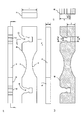
- Example 1 shows a partition plate of Example 1,
- A is a six-sided view in which a rear view and a left side view are omitted,
- B is an aa sectional view, and
- C is a bb sectional view.
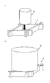
- the mode that the partition plate of Example 1 is assembled and it is set as a buffer material is shown,
- A) is a perspective view of a partition plate,
- B) is a perspective view of the buffer material in the middle of an assembly,
- (B) is the buffer material after completion of an assembly.
- the shock absorbing material formed by assembling the partition plate of Example 1 is shown, (A) is a plan view, (B) is a cc enlarged sectional view, (C) is a dd enlarged sectional view, and (D) is e. -E is an enlarged sectional view.
- the usage example of the shock absorbing material of Example 1 is shown, (A) is a perspective view of a mode that an article is stored and used between the meshes as a partition, and (B) is used by placing the article on the upper surface as a cradle. It is a perspective view which shows a mode.
- the partition plate of Example 2 is shown, (A) is a six-sided view in which the rear view and the left side view are omitted, (B) is an ff sectional view, and (C) is a gg sectional view.
- the usage example of the shock absorbing material which assembled the partition plate of Example 2 is shown, (A) is a perspective view before an assembly, (B) is a perspective view which shows a mode that it uses as a cradle for mounting a spherical article after completion of an assembly. It is.
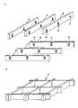
- the mode that the partition plate of Example 3 is assembled and it is set as a shock absorbing material is shown, (A) is a perspective view before an assembly, (B) is a perspective view after the completion of an assembly.
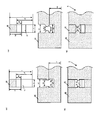
- the usage example of the buffer material of Example 3 is shown, (A) is a perspective view of a mode that the article is stored and used between the meshes as a partition, and (B) is used by placing the article on the upper surface as a cradle. It is a perspective view which shows a mode. Another example is shown, (A) is an enlarged cross-sectional view of the main part before assembly of Example 4, (B) is an enlarged cross-sectional view of the main part after completion of assembly of Example 3, and (C) is that of Example 4. The principal part expanded sectional view before an assembly is shown, (D) is the principal part expanded sectional view after the assembly of Example 5 is completed.
- FIG. 1A is a six-sided view in which a rear view and a left side view are omitted
- FIG. 1B is a cross-sectional view along aa
- FIG. b shows a cross-sectional view.
- the partition plate 10 includes groove portions 20 and 20 formed so that the upper side is the opening 21.
- the groove portions 20 and 20 have the same shape, and are formed such that the depth d1 from the opening 21 to the groove bottom 22 is larger than 1 ⁇ 2 of the height h of the partition plate 10.
- Protrusions 30 and 30 projecting into the groove are provided at positions between the bottom 22.
- the protrusion 30 is a tapered surface 32 having a slope that increases in height as the groove bottom 22 side is a horizontal plane 31 and the opening 21 side is away from the groove center. It protrudes from both the left and right groove side walls 23 and 24 so as to protrude to the position of the height h1 that is closer to the opening 21 than 1/2 of the height h.
- the groove portions 20 and 20 are also provided with vertical portions 25 and 26 having a width b1 substantially equal to the plate thickness t of the partition plate 10 between the protrusion portions 30 and 30 to the opening 21. And between the protrusions 30 and 30 to the groove bottom 22, a width b2 that does not protrude inward from the extension line of the vertical parts 25 and 26, and a depth d2 that can store the protrusions 30 and 30 ,have. Furthermore, tapered surfaces 27 and 28 that are outwardly opened are formed on the opening 21 side of the vertical portions 25 and 26. As shown in the drawing, the groove portions 20 and 20 of the partition plate 10 are formed so that the groove side walls 23 and 24 are of the same shape with left-right symmetry.
- a low-foaming PP sheet manufactured by Mitsui Chemicals Tosero Co., Ltd., product name: Palonia (registered trademark), polypropylene triple-extrusion foamed sheet
- t 10 mm
- h 30 mm
- d1 21 mm
- h1 15.5 mm
- d2 6.5 mm.
- b3 6 in this embodiment so that the tip of the protrusion 30 is chamfered vertically and the gap b3 between the left and right protrusions is within a range of 50% to 80% with respect to the plate thickness t. .2 mm (62% of t).
- FIG. 2 (B) As shown in FIG. 2 (B), four partition plates 10 of this embodiment are prepared, and are assembled in a cross-beam shape by shifting them 90 degrees upside down so as to engage each other.
- the cushioning material 1 shown in C) is used for packaging.
- partition plate 11 the inclined surface of the projection 30 of the partition plate
- partition plate 12 the projection 30 of the partition plate meshed from below.
- each partition plate 11, 12 is formed so that the groove portion 20 is “a depth d 1 from the opening 21 to the groove bottom 22 is greater than 1 ⁇ 2 of the height h of the partition plate 11 (12)”.
- a width b2 that does not protrude inward from the extension line of the vertical portions 25 and 26 and a depth d2 that can accommodate the protrusion 30. Therefore, as shown in FIGS. 3 (B) and 3 (C), the protrusions 30 are accommodated in the groove bottom portion on the other side with the other protrusions 30 crossing each other.
- the vertical portions 25 and 26 having substantially the same width b1 as the plate thickness t of the partition plate 11 (12) are provided between the protruding portion 30 and the opening 21, the vertical portions 25 of the respective groove portions 20 are provided. , 26 serve as a guide for the outer surface of the other partition plate 11 (12), aligning the meshing direction, and preventing the partition plate 11 (12) from falling after meshing.
- the protrusion 30 is formed as “a taper surface 32 having a slope that increases in height as the groove bottom 22 side becomes the horizontal plane 31 and the opening 21 side is away from the groove center, and the horizontal plane 31 extends from the groove bottom 22 to the partition plate.
- 11 (12) protrudes from both the left and right groove sidewalls 23 and 24 so as to protrude to the position of the height h1 on the opening 21 side than 1/2 of the height h of FIG. 3 (12).
- the horizontal surface 31 of the protrusion 30 of the upper partition plate 11 is the horizontal surface 31 of the protrusion 30 of the lower partition plate 12, and the horizontal surface 31 of the lower protrusion 30 is the upper protrusion. It is located on the horizontal surface 31 of the part 30, and in this state, the outer corners 35 overlap with each other to prevent each other from coming out.
- partition plate 11 and partition plate 12 This prevents the assembled partition plate 11 and partition plate 12 from being inadvertently detached. Although it does not come off inadvertently in this way, the partition plates are not separated from each other, and can be disassembled if the partition plate 11 (12) is intentionally extracted.
- the groove side walls 23 and 24 are symmetric, the deformation of the protrusion 30 occurs almost symmetrically, and the engagement between the horizontal surfaces 31 in the assembled state is also symmetric. The work can be performed smoothly and the effect of preventing the removal in the assembled state is also exhibited appropriately.
- the partition plates can be slightly engaged from each other in an oblique direction, or the partition plates can be slightly pulled out in an oblique direction, Assembly work and disassembly work can be further facilitated.
- the cushioning material 1 of the present embodiment is formed of a low foam material, it has appropriate hardness and cushioning properties. As a result, as shown in FIG. 4A, the article W2 is placed on the upper surface as shown in FIG. It can also be used as a cradle to be placed. In addition, since the cushioning material 1 of this embodiment is easy to assemble and disassemble, it is transported to the packing site in a disassembled state, and after unpacking, it is disassembled again and transported to a material warehouse or another site. can do.
- FIG. 5 (A) is a six-side view in which the rear view and the left side view are omitted
- FIG. 5 (B) is a sectional view taken along line ff
- FIG. g shows a cross-sectional view.
- the partition plate 40 has the same material, t, h, h1, d1, d2, b1, and b2 dimensions as in the first embodiment, and the groove 20 has the same dimensions and shape as in the first embodiment.
- arc-shaped concave portions 41 and 42 are provided at the center portions of the upper surface and the lower surface, respectively.
- FIG. 6 (A) four partition plates 40 of the present embodiment are prepared and shifted 90 degrees upside down so as to mesh with each other, and assembled into a cross-beam shape as shown in FIG. It is used for packaging and packing as the cushioning material 2 shown in B). Since the shock-absorbing material 2 of Example 2 is provided with arc-shaped concave portions 41 and 42 on the upper surface when assembled in a cross-beam shape, it can be used as a cradle for placing a spherical article W3.
- FIG. 7A is a perspective view before assembly of the cushioning material 3 of Example 3, and FIG. 7B is a perspective view after completion of assembly.
- the partition plate 10 including the two groove portions 20 is used in the cushioning material 1 of the first embodiment.
- the buffer material 3 of the third embodiment is different in that the partition plate 50 including the three groove portions 20 at equal intervals is used.
- the cushioning material 3 of Example 3 is provided with four cells by assembling a total of six partition plates 50 in the same manner as in Example 1, three on the upper side and three on the lower side. It is assembled.
- the material and the dimensions of each groove 20 are the same as those in the first embodiment.
- the cushioning material 3 of the present embodiment can be used as a partition for storing the articles W3a to w3d between the meshes assembled in the form of a cross girder, as shown in FIG. 8 (B). As shown, it can also be used as a cradle for placing the article W4 on the upper surface.
- Example 4 is a cushioning material 4 that employs partition plates 61 and 62 having rectangular cross-section protrusions 71 and 72 as protrusions, as shown in FIGS. 9 (A) and 9 (B).
- the dimensions of the material, t, h, h1, d1, d2, b1, b2 are the same as in Example 1, but the gap b4 between the protrusions is 80% of the plate thickness t.
- the projection 71 of the upper partition plate 61 and the projection 72 of the lower partition plate 62 abut each other at the outer corners, and the other storage portion is slightly deformed. It is stored in.
- the protrusion part 71 and the protrusion part 72 prevent inadvertent pull-out at the outer corners. Further, at the time of disassembly, the outer corner of the projection 71 and the outer corner of the projection 72 that functioned as prevention of slipping out are slightly deformed, so that slipping out is not hindered in intentional disassembly work.
- Example 5 is a cushioning material 5 that employs partition plates 81 and 82 having semicircular cross-sectional protrusions 91 and 92 as protrusions, as shown in FIGS. 9 (C) and (D).
- the dimensions of the material, t, h, h1, d1, d2, b1, b2 are the same as in Example 1, but the gap b5 between the protrusions is 50% of the plate thickness t.
- the protruding portion 91 of the upper partition plate 81 and the protruding portion 92 of the lower partition plate 82 are in contact with each other at the outer corners, and the other storage portion is slightly deformed. It is stored in.
- the protruding portion 91 and the protruding portion 92 prevent inadvertent withdrawal at the outer corners. Further, at the time of disassembly, the outer corners of the protrusion 91 and the outer corners of the protrusion 92 that functioned as a prevention of slipping out are slightly deformed, so that the pulling out is not hindered in the intentional disassembly work.
- each embodiment it is possible to provide a cushioning material that can be easily assembled and disassembled without increasing the types of components and that prevents the partition plate from being inadvertently removed after assembly. .
- a low foaming PP sheet a low foaming polyester sheet may be used, and the foaming magnification and the plate thickness are not limited to those of the example, and when used as a cradle, Of the foamed plastics having an expansion ratio of 2 to 8 times and a plate thickness of 3 to 20 mm, those having hardness and cushioning properties suitable for the object to be packaged and packed may be adopted.
- the present invention is not limited to the packaging / packaging cushioning material, and can be used for various uses other than packaging / packaging, for example, installed under a floor board as a cushioning material for a floor having cushioning properties.
Landscapes
- Engineering & Computer Science (AREA)
- Mechanical Engineering (AREA)
- Buffer Packaging (AREA)
Abstract
Provided is a cushioning material which can be easily assembled and dissembled since there is no increase in the number of types of parts and which has a partition plate provided so as not to be detached inadvertently after the cushioning material is assembled. Grooves (20) of this partition plate (10) each satisfy "1/2 (height h of partition plate)" < "depth d1", and are each provided with protrusions (30) protruding within the groove. The protrusions (30) symmetrically protrude from both left and right groove side walls (23, 24) so as to have groove-bottom side horizontal surfaces (31) protruding at a position of the height h1 which is closer to the opening than the half of [height h of partition plate] from the groove bottom. Vertical sections (25, 26) each having a width b1 substantially equal to "plate thickness t of partition plate" are provided between the protrusions and an opening. A section between the protrusions and the groove bottom has a width b2 so as not to protrude beyond extension lines of the vertical sections, and a depth d2 large enough to house the protrusions (30). Outwardly opening tapered surfaces (27, 28) are also formed at the opening side.
Description
本発明は、仕切板を組み立ててなる緩衝材及び当該仕切板に関するものである。
The present invention relates to a cushioning material obtained by assembling a partition plate and the partition plate.
物品を包装する際、下向き溝を備える仕切板と上向き溝を備える仕切板とを溝同士を噛み合わせる様に組み立てて井桁状に組んだ緩衝材が用いられることが多い。
When packaging an article, a cushioning material is often used in which a partition plate having a downward groove and a partition plate having an upward groove are assembled so that the grooves are engaged with each other and assembled in a cross-beam shape.
こうした仕切板とし低発泡材やプラスチック製段ボールを用いた緩衝材の提案がある(特許文献1,特許文献2)。
There is a proposal of a cushioning material using a low foam material or plastic corrugated cardboard as such a partition plate (Patent Document 1, Patent Document 2).
特許文献1に記載された緩衝材は、コ字状の切り込みが形成された第1の仕切板と、端部に上下から切り込みを入れた第2の仕切板とを用いることから、部品の種類が増加するという問題がある。また、組立に当たっては、第2の仕切板の端部の切り込みを横に折り曲げて第1の仕切板のコ字状の切り込みに差し込んだ後に折り曲げた部分を再び伸ばす作業が必要で手間がかかると共に、素材がプラスチック製段ボールに限られるという問題がある。
The cushioning material described in Patent Document 1 uses a first partition plate in which a U-shaped cut is formed and a second partition plate in which an end is cut from above and below, so that the type of component There is a problem that increases. In addition, when assembling, it is necessary to fold the notch at the end of the second partition plate to the side, insert it into the U-shaped notch of the first partition plate, and then extend the folded portion again. There is a problem that the material is limited to plastic cardboard.
特許文献2に記載された緩衝材は、複数の直線溝を備える同タイプの仕切板同士を組み合わせる構造であることから部品の種類は増加せず、組立も容易であるが、外れない様にするために底板を熱溶着させる必要があり、結局のところ、部品の種類の減少や組み立て作業の容易化は達成できていない。また、一旦組み立てると分解できないという問題もある。
The cushioning material described in Patent Document 2 has a structure in which the same type of partition plates having a plurality of linear grooves are combined with each other, so that the types of parts are not increased and the assembly is easy, but it is prevented from coming off. Therefore, it is necessary to heat-seal the bottom plate. After all, the number of parts and the ease of assembly work cannot be achieved. There is also a problem that once assembled, it cannot be disassembled.
そこで、本発明は、部品の種類を増加させることなく組立・分解が容易であって、組み立てた後に仕切板が不用意に外れることのない緩衝材を提供することを目的とする。
Therefore, an object of the present invention is to provide a cushioning material that can be easily assembled and disassembled without increasing the types of parts, and from which a partition plate does not come off carelessly after assembly.
上記目的を達するためになされた本発明の仕切板は、上下一方側を開口とする様に形成された溝部が以下の構成を備えていることを特徴とする。
(1A)前記溝部は、前記開口から溝底までの深さが当該仕切板の高さの1/2よりも大きくなる様に形成されると共に、前記開口と前記溝底との間において溝内に向かって突出する突起部が、前記溝底から当該仕切板の高さの1/2よりも開口側となる高さの位置へと突出する様に前記左右の溝側壁の両方から突出されていること。
(1B)前記溝部は、前記突起部から前記開口までの間に、当該仕切板の板厚とほぼ同一幅の垂直部を備えると共に、前記突起部から前記溝底までの間は、前記垂直部の延長線よりも内側に突出することのない幅と、前記突起部を収納可能な深さと、を有していること。 In order to achieve the above object, the partition plate of the present invention is characterized in that a groove portion formed so as to have an opening on one of the upper and lower sides has the following configuration.
(1A) The groove portion is formed such that a depth from the opening to the groove bottom is larger than ½ of the height of the partition plate, and the groove portion is formed between the opening and the groove bottom. Projecting from both the left and right groove sidewalls so as to project from the groove bottom to a position on the opening side of the height of half of the partition plate. Being.
(1B) The groove includes a vertical portion having substantially the same width as the partition plate between the protrusion and the opening, and the vertical portion extends from the protrusion to the groove bottom. A width that does not protrude inward from the extension line of the first and a depth that allows the protrusion to be accommodated.
本発明の仕切板を複数枚用意し、互いの溝部を噛み合わせる様に上下反対に90度ずらして井桁状に組み立てるとき、上方から噛み合わされる仕切板(以下、「上側の仕切板」という)の突起部と、下方から噛み合わされる仕切板(以下、「下側の仕切板」という)の突起部とが外側隅同士で当接する。こうして突起部の外側隅同士を当接させた仕切板同士をさらに深く噛み合わせる様に押し込み合う様にすると、それぞれの突起部は、外側隅を若干変形させつつ相手側の溝底方向へと侵入する。このとき、各仕切板は、溝部の深さ及び突起部の位置が(1A)に記載の構成を有すると共に、突起部から溝底までの間の幅及び深さが(1B)に記載の構成を有しているから、突起部は互いに相手の突起部を交わして溝底部分へと収納される。また、突起部から開口までの間に(1B)に記載の直線部を有しているから、それぞれの溝部の垂直部が、相手の仕切板の外面に対するガイドとなり、噛み合い方向を整列させると共に、噛み合った後は仕切板の倒れを防止する。そして、突起部の突出位置が(1A)に記載の構成を有すると共に、突起部から溝底までの間の幅及び高さが(1B)に記載の構成を有しているから、上側の仕切板の突起部は下側の仕切板の突起部の下側に、下側の仕切板の突起部の水平面は上側の仕切板の上側に位置し、互いに相手の抜け出しを阻止し合った状態となる。これにより、組立後の仕切板が不用意に外れることがない。この様に不用意に外れることはないが、仕切板同士は溶着されている分けではないから、意図的に仕切板を抜き取る様に操作すれば、分解することもできる。
A plurality of partition plates of the present invention are prepared, and when assembled in a cross-beam shape by shifting 90 degrees upside down so as to mesh each other's grooves, a partition plate meshed from above (hereinafter referred to as “upper partition plate”) And the projections of a partition plate (hereinafter referred to as “lower partition plate”) engaged from below are brought into contact with each other at the outer corners. In this way, when the partition plates that contact the outer corners of the protrusions are pushed into each other so as to engage more deeply, each protrusion enters the opposite groove bottom direction while slightly deforming the outer corners. To do. At this time, each partition plate has a configuration in which the depth of the groove and the position of the protrusion are described in (1A), and the width and depth from the protrusion to the groove bottom are described in (1B). Therefore, the protrusions are accommodated in the groove bottom portion with the other protrusions crossing each other. Moreover, since it has the linear part as described in (1B) between the protrusion part and the opening, the vertical part of each groove part serves as a guide for the outer surface of the other partition plate, and aligns the meshing direction, After engaging, the partition plate is prevented from falling. And since the protrusion position of a projection part has the structure as described in (1A), and the width and height from a protrusion part to a groove bottom have the structure as described in (1B), it is an upper partition. The projections of the plate are located below the projections of the lower partition plate, the horizontal surfaces of the projections of the lower partition plate are located above the upper partition plate, and prevent each other from coming out. Become. Thereby, the partition plate after an assembly does not remove carelessly. Although it does not come off inadvertently in this way, the partition plates are not separated from each other, and can be disassembled if the partition plate is intentionally extracted.
上記目的を達するためになされた本発明の仕切板は、上下一方側を開口とする様に形成された溝部が以下の構成を備えていることを特徴とする。
(2A)前記溝部は、前記開口から溝底までの深さが当該仕切板の高さの1/2よりも大きくなる様に形成されると共に、前記開口と前記溝底との間において溝内に向かって突出する突起部が備えられていること。
(2B)前記突起部は、溝底側が水平面とされると共に開口側が溝中心から離れるほど高さが大きくなる傾斜を有するテーパ面とされ、前記水平面が、前記溝底から当該仕切板の高さの1/2よりも開口側となる高さの位置へと突出する様に前記左右の溝側壁の両方から突出されていること。
(2C)前記溝部は、前記突起部から前記開口までの間に、当該仕切板の板厚とほぼ同一幅の垂直部を備えていること。
(2D)前記突起部から前記溝底までの間は、前記垂直部の延長線よりも内側に突出することのない幅と、前記突起部を収納可能な深さと、を有していること。 In order to achieve the above object, the partition plate of the present invention is characterized in that a groove portion formed so as to have an opening on one of the upper and lower sides has the following configuration.
(2A) The groove portion is formed so that a depth from the opening to the groove bottom is larger than ½ of a height of the partition plate, and the groove portion is formed in the groove between the opening and the groove bottom. Protruding part protruding toward
(2B) The protruding portion is a tapered surface having a slope whose height increases as the groove bottom side is a horizontal plane and the opening side is away from the groove center, and the horizontal plane is a height of the partition plate from the groove bottom. It protrudes from both of the left and right groove sidewalls so as to protrude to a position at a height that is closer to the opening side than 1/2.
(2C) The groove includes a vertical portion having a width substantially the same as the thickness of the partition plate between the protrusion and the opening.
(2D) The space from the protrusion to the groove bottom has a width that does not protrude inward from the extension line of the vertical portion and a depth that allows the protrusion to be accommodated.
本発明の仕切板を複数枚用意し、互いの溝部を噛み合わせる様に上下反対に90度ずらして井桁状に組み立てるとき、上方から噛み合わされる仕切板(以下、「上側の仕切板」という)の突起部の傾斜面と、下方から噛み合わされる仕切板(以下、「下側の仕切板」という)の突起部の傾斜面とが外側の隅同士で当接する。こうして突起部の外側隅同士を当接させた仕切板同士をさらに深く噛み合わせる様に押し込み合う様にすると、それぞれの突起部は外側隅同士は、相手側の傾斜面に沿って若干変形しつつ相手側の溝底方向へと侵入する。このとき、各仕切板は、溝部が(2A)の構成を有すると共に、突起部から溝底までの間が(2D)の構成を有しているから、突起部は互いに相手の突起部を交わして溝底部分へと収納される。また、突起部から開口までの間に(2C)の構成を有しているから、それぞれの溝部の垂直部が、相手の仕切板の外面に対するガイドとなり、噛み合い方向を整列させると共に、噛み合った後は仕切板の倒れを防止する。そして、突起部が(2B)の構成を有しているから、上側の仕切板の突起部の水平面は下側の仕切板の突起部の水平面の上側に、下側の仕切板の突起部の水平面は上側の仕切板の突起部の水平面の上側に位置し、互いに相手の抜け出しを阻止し合った状態となる。これにより、組立後の仕切板が不用意に外れることがない。この様に不用意に外れることはないが、仕切板同士は溶着されている分けではないから、意図的に仕切板を抜き取る様に操作すれば、分解することもできる。特に、水平面同士の係合によって不用意な分解がより確実に阻止される。
A plurality of partition plates of the present invention are prepared, and when assembled in a cross-beam shape by shifting 90 degrees upside down so as to mesh each other's grooves, a partition plate meshed from above (hereinafter referred to as “upper partition plate”) And the inclined surface of the protruding portion of the partition plate (hereinafter referred to as “lower partition plate”) meshed from below are in contact with each other at the outer corners. If the partition plates that contact the outer corners of the projections are pushed in so as to engage more deeply, the outer corners of the projections are slightly deformed along the other inclined surface. Invade toward the other side of the groove. At this time, each partition plate has a configuration of (2A) in the groove portion and a (2D) configuration from the projection portion to the bottom of the groove, so that the projection portion crosses the other projection portion. And stored in the bottom of the groove. In addition, since the structure of (2C) is provided between the protrusion and the opening, the vertical portion of each groove serves as a guide for the outer surface of the other partition plate, aligns the meshing direction, and after meshing Prevents the divider from falling over. And since a projection part has the structure of (2B), the horizontal surface of the projection part of an upper partition plate is above the horizontal surface of the projection part of a lower partition plate, and the projection part of a lower partition plate The horizontal plane is located above the horizontal plane of the protrusion of the upper partition plate and is in a state in which the other party is prevented from coming out. Thereby, the partition plate after an assembly does not remove carelessly. Although it does not come off inadvertently in this way, the partition plates are not separated from each other, and can be disassembled if the partition plate is intentionally extracted. In particular, inadvertent disassembly is more reliably prevented by the engagement between the horizontal surfaces.
ここで、本発明の仕切板は、さらに、以下の構成をも備えるとよい。
(3)前記溝部は、溝側壁が左右対称となる様に形成されていること。 Here, the partition plate of the present invention may further include the following configuration.
(3) The groove is formed so that the groove side wall is symmetrical.
(3)前記溝部は、溝側壁が左右対称となる様に形成されていること。 Here, the partition plate of the present invention may further include the following configuration.
(3) The groove is formed so that the groove side wall is symmetrical.
溝側壁が左右対称とされることにより、突起部の変形はほぼ左右対称に生じ、組立られた状態における水平面同士の係り合いも左右対称であるから、組立作業・分解作業をスムーズに実行することができると共に、組み立てた状態における抜け出し防止効果も適切に発揮される。
By making the groove side walls symmetrical, the deformation of the protrusions occurs almost symmetrically, and the horizontal planes in the assembled state are also symmetrical, so that assembly and disassembly work can be performed smoothly. In addition, the effect of preventing slipping out in the assembled state is also exhibited appropriately.
また、これら本発明の仕切板は、さらに、以下の構成をも備えるとよい。
(4)前記垂直部の開口側には、外開きとなるテーパ面が形成されていること。 Moreover, these partition plates of the present invention may further include the following configuration.
(4) A tapered surface that opens outward is formed on the opening side of the vertical portion.
(4)前記垂直部の開口側には、外開きとなるテーパ面が形成されていること。 Moreover, these partition plates of the present invention may further include the following configuration.
(4) A tapered surface that opens outward is formed on the opening side of the vertical portion.
溝部の開口側を外開きのテーパ面とすることにより、仕切板同士を若干斜め方向から噛み合わせたり、仕切板同士を若干斜め方向に引き抜いたりすることができ、組立作業・分解作業を、さらに容易にすることができる。
By making the opening side of the groove part an outwardly opening tapered surface, the partition plates can be engaged with each other from a slightly oblique direction, or the partition plates can be slightly pulled out in a slightly oblique direction. Can be easily.
上記目的を達するためになされた本発明の緩衝材は、上下一方側を開口とする溝部が形成された複数枚の仕切板同士を、互いに溝部同士を噛み合わせる様に井桁状に組み立てられた緩衝材あって、前記複数枚の仕切板のそれぞれが、以下の構成を備えていることを特徴とする。
(5A)前記仕切板は発泡プラスチックで形成されると共に、前記溝部は左右対称となる溝側壁を有していること。
(5B)前記溝部は、前記開口から溝底までの深さが当該仕切板の高さの1/2よりも大きくなる様に形成されると共に、前記開口と前記溝底との間において溝内に向かって突出する突起部が備えられていること。
(5C)前記突起部は、溝底側が水平面とされると共に開口側が溝中心から離れるほど高さが大きくなる傾斜を有するテーパ面とされ、前記水平面が、前記溝底から当該仕切板の高さの1/2よりも開口側となる高さの位置へと突出する様に前記左右の溝側壁の両方から突出されていること。
(5D)前記溝部は、前記突起部から前記開口までの間に、当該仕切板の板厚とほぼ同一幅の垂直部を備えていること。
(5E)前記突起部から前記溝底までの間は、前記垂直部の延長線よりも内側に突出することのない幅と、前記突起部を収納可能な深さと、を有していること。
(5F)前記垂直部の開口側には、外開きとなるテーパ面が形成されていること。 The cushioning material of the present invention, which has been made to achieve the above object, is a cushioning material that is assembled in a grid pattern so that a plurality of partition plates having grooves formed on one side of the upper and lower sides are meshed with each other. There are materials, and each of the plurality of partition plates has the following configuration.
(5A) The partition plate is made of foamed plastic, and the groove has groove sidewalls that are symmetrical.
(5B) The groove portion is formed so that a depth from the opening to the groove bottom is larger than ½ of the height of the partition plate, and the groove portion is formed between the opening and the groove bottom. Protruding part protruding toward
(5C) The protrusion is a tapered surface having a slope whose height increases as the groove bottom side is a horizontal plane and the opening side is away from the groove center. The horizontal plane is a height of the partition plate from the groove bottom. It protrudes from both of the left and right groove sidewalls so as to protrude to a position at a height that is closer to the opening side than 1/2.
(5D) The groove includes a vertical portion having substantially the same width as the partition plate between the protrusion and the opening.
(5E) The space from the protrusion to the groove bottom has a width that does not protrude inward from the extension line of the vertical portion and a depth that allows the protrusion to be accommodated.
(5F) A tapered surface that opens outward is formed on the opening side of the vertical portion.
本発明の緩衝材によれば、発泡プラスチックで形成された仕切板は、組立・分解の際に、突起部を変形させ得る反面、組立られている状態においては、突起部は元の形状に復元する。この結果、発泡倍率2倍~8倍、板厚10mm~20mmといった市販の低発泡性押出成形シート材を用いて、トムソン抜型によって打ち抜き加工する方法で仕切板を製造することもできる。一方、発泡プラスチックシート材をトムソン抜型で打ち抜き加工するに当たっては、打ち抜いた部分を抜型から自動排出することを考慮すると、板厚3mm以上とすることが望ましい。従って、本発明の緩衝材を物品を下から支える受け台として使用する場合は、発泡倍率2倍~8倍、板厚3~20mmの低発泡材(低発泡ポリプロピレン、低発泡ポリスチレン等)を用いると、所望の機能を有する緩衝材用仕切板をトムソン抜型を用いて製造することができる。
According to the cushioning material of the present invention, the partition plate formed of foamed plastic can deform the projection during assembly / disassembly, but the projection is restored to its original shape in the assembled state. To do. As a result, the partition plate can also be manufactured by a method of punching by Thomson punching using a commercially available low foaming extruded sheet material having a foaming ratio of 2 to 8 times and a plate thickness of 10 mm to 20 mm. On the other hand, when the foamed plastic sheet material is punched with a Thomson die, it is desirable to set the thickness to 3 mm or more in consideration of automatically discharging the punched portion from the die. Therefore, when the cushioning material of the present invention is used as a cradle for supporting an article from below, a low foam material (low foam polypropylene, low foam polystyrene, etc.) having a foaming ratio of 2 to 8 times and a plate thickness of 3 to 20 mm is used. And the partition plate for buffer materials which has a desired function can be manufactured using a Thomson die.
本発明によれば、部品の種類を増加させることなく組立・分解が容易であって、組み立てた後に仕切板が不用意に外れることのない様にした緩衝材を提供することができる。
According to the present invention, it is possible to provide a cushioning material that can be easily assembled and disassembled without increasing the types of parts, and prevents the partition plate from being unintentionally detached after assembly.
以下に、本発明を実施するための形態を実施例に基づいて説明する。
Hereinafter, modes for carrying out the present invention will be described based on examples.
実施例1の仕切板10について、図1(A)に背面図と左側面図を省略した六面図を、図1(B)にa-a断面図を、図1(C)にb-b断面図を示す。
As for the partition plate 10 of the first embodiment, FIG. 1A is a six-sided view in which a rear view and a left side view are omitted, FIG. 1B is a cross-sectional view along aa, and FIG. b shows a cross-sectional view.
仕切板10は、上側を開口21とする様に形成された溝部20,20を備えている。溝部20,20は、同一形状であり、開口21から溝底22までの深さd1が当該仕切板10の高さhの1/2よりも大きくなる様に形成されると共に、開口21と溝底22との間の位置に溝内に向かって突出する突起部30,30が備えられている。
The partition plate 10 includes groove portions 20 and 20 formed so that the upper side is the opening 21. The groove portions 20 and 20 have the same shape, and are formed such that the depth d1 from the opening 21 to the groove bottom 22 is larger than ½ of the height h of the partition plate 10. Protrusions 30 and 30 projecting into the groove are provided at positions between the bottom 22.
突起部30は、溝底22側が水平面31とされると共に開口21側が溝中心から離れるほど高さが大きくなる傾斜を有するテーパ面32とされ、水平面31が、溝底22から当該仕切板10の高さhの1/2よりも開口21側となる高さh1の位置へ突出する様に左右の溝側壁23,24の両方から突出されている。
The protrusion 30 is a tapered surface 32 having a slope that increases in height as the groove bottom 22 side is a horizontal plane 31 and the opening 21 side is away from the groove center. It protrudes from both the left and right groove side walls 23 and 24 so as to protrude to the position of the height h1 that is closer to the opening 21 than 1/2 of the height h.
溝部20,20は、また、突起部30,30から開口21までの間に、当該仕切板10の板厚tとほぼ同一幅b1の垂直部25,26を備えている。そして、突起部30,30から溝底22までの間は、垂直部25,26の延長線よりも内側に突出することがない幅b2と、突起部30,30を収納可能な深さd2と、を有している。さらに、垂直部25,26の開口21側には、外開きとなるテーパ面27,28が形成されている。そして、図示の様に、仕切板10の各溝部20,20は、いずれも溝側壁23,24が左右対称の同一形状のものとして形成されている。
The groove portions 20 and 20 are also provided with vertical portions 25 and 26 having a width b1 substantially equal to the plate thickness t of the partition plate 10 between the protrusion portions 30 and 30 to the opening 21. And between the protrusions 30 and 30 to the groove bottom 22, a width b2 that does not protrude inward from the extension line of the vertical parts 25 and 26, and a depth d2 that can store the protrusions 30 and 30 ,have. Furthermore, tapered surfaces 27 and 28 that are outwardly opened are formed on the opening 21 side of the vertical portions 25 and 26. As shown in the drawing, the groove portions 20 and 20 of the partition plate 10 are formed so that the groove side walls 23 and 24 are of the same shape with left-right symmetry.
なお、本実施例では、仕切板10の素材として、低発泡性PPシート(三井化学東セロ株式会社製、製品名:パロニア(登録商標)、ポリプロピレン3倍押出発泡シート)を用いた。また、具体的な寸法としては、t=10mm、b1=b2=10.2mm、h=30mm、d1=21mm、h1=15.5mm、d2=6.5mmとした。また、突起部30の先端は垂直に面取りを施すと共に、左右の突起部間の隙間b3を、板厚tに対して50%~80%の範囲内とすべく、本実施例ではb3=6.2mm(tの62%)とした。
In this example, a low-foaming PP sheet (manufactured by Mitsui Chemicals Tosero Co., Ltd., product name: Palonia (registered trademark), polypropylene triple-extrusion foamed sheet) was used as the material of the partition plate 10. Further, as specific dimensions, t = 10 mm, b1 = b2 = 10.2 mm, h = 30 mm, d1 = 21 mm, h1 = 15.5 mm, d2 = 6.5 mm. In addition, b3 = 6 in this embodiment so that the tip of the protrusion 30 is chamfered vertically and the gap b3 between the left and right protrusions is within a range of 50% to 80% with respect to the plate thickness t. .2 mm (62% of t).
本実施例の仕切板10を4枚用意し、図2(B)に示す様に、互いの溝部20同士を噛み合わせる様に上下反対に90度ずらして井桁状に組み立てることにより、図2(C)に示す緩衝材1として包装・梱包に用いる。
As shown in FIG. 2 (B), four partition plates 10 of this embodiment are prepared, and are assembled in a cross-beam shape by shifting them 90 degrees upside down so as to engage each other. The cushioning material 1 shown in C) is used for packaging.
組立に当たって、上方から噛み合わされる仕切板(以下、「仕切板11」という)の突起部30の傾斜面と、下方から噛み合わされる仕切板(以下、「仕切板12」という)の突起部30の傾斜面とが外側隅35(図3(D),(E)参照)同士で当接する。こうして突起部30の外側隅35同士を当接させた仕切板11と仕切板12とをさらに深く噛み合わせる様に押し込み合う様にすると、それぞれの突起部30は外側隅同士は、若干変形しつつ相手側の溝底方向へと侵入する。
In assembly, the inclined surface of the projection 30 of the partition plate (hereinafter referred to as “partition plate 11”) meshed from above and the projection 30 of the partition plate (hereinafter referred to as “partition plate 12”) meshed from below. Are in contact with each other at the outer corners 35 (see FIGS. 3D and 3E). Thus, when the partition plate 11 and the partition plate 12 with which the outer corners 35 of the projections 30 are brought into contact with each other are pushed in so as to engage further, the outer corners of the projections 30 are slightly deformed. Invade toward the other side of the groove.
このとき、各仕切板11,12は、溝部20が、「開口21から溝底22までの深さd1が当該仕切板11(12)の高さhの1/2よりも大きくなる様に形成」され、「突起部30から溝底22までの間は、垂直部25,26の延長線よりも内側に突出することのない幅b2と、突起部30を収納可能な深さd2と」を有しているから、図3(B),(C)に示す様に、突起部30は互いに相手の突起部30を交わして相手側の溝底部分へと収納される。
At this time, each partition plate 11, 12 is formed so that the groove portion 20 is “a depth d 1 from the opening 21 to the groove bottom 22 is greater than ½ of the height h of the partition plate 11 (12)”. "Between the protrusion 30 and the groove bottom 22, a width b2 that does not protrude inward from the extension line of the vertical portions 25 and 26 and a depth d2 that can accommodate the protrusion 30". Therefore, as shown in FIGS. 3 (B) and 3 (C), the protrusions 30 are accommodated in the groove bottom portion on the other side with the other protrusions 30 crossing each other.
また、突起部30から開口21までの間に「当該仕切板11(12)の板厚tとほぼ同一幅b1の垂直部25,26」を備えているから、それぞれの溝部20の垂直部25,26が、相手の仕切板11(12)の外面に対するガイドとなり、噛み合い方向を整列させると共に、噛み合った後は仕切板11(12)の倒れを防止する。
Further, since “the vertical portions 25 and 26 having substantially the same width b1 as the plate thickness t of the partition plate 11 (12)” are provided between the protruding portion 30 and the opening 21, the vertical portions 25 of the respective groove portions 20 are provided. , 26 serve as a guide for the outer surface of the other partition plate 11 (12), aligning the meshing direction, and preventing the partition plate 11 (12) from falling after meshing.
そして、突起部30が「溝底22側が水平面31とされると共に開口21側が溝中心から離れるほど高さが大きくなる傾斜を有するテーパ面32とされ、水平面31が、溝底22から当該仕切板11(12)の高さhの1/2よりも開口21側の高さh1の位置へ突出する様に左右の溝側壁23,24の両方から突出」されているから、図3(B)~(E)に示す様に、上側の仕切板11の突起部30の水平面31は下側の仕切板12の突起部30の水平面31に、下側の突起部30の水平面31は上側の突起部30の水平面31の上に位置し、この状態で外側隅35同士が重なり合って互いに相手の抜け出しを阻止し合った状態となる。
Then, the protrusion 30 is formed as “a taper surface 32 having a slope that increases in height as the groove bottom 22 side becomes the horizontal plane 31 and the opening 21 side is away from the groove center, and the horizontal plane 31 extends from the groove bottom 22 to the partition plate. 11 (12) protrudes from both the left and right groove sidewalls 23 and 24 so as to protrude to the position of the height h1 on the opening 21 side than 1/2 of the height h of FIG. 3 (12). (E), the horizontal surface 31 of the protrusion 30 of the upper partition plate 11 is the horizontal surface 31 of the protrusion 30 of the lower partition plate 12, and the horizontal surface 31 of the lower protrusion 30 is the upper protrusion. It is located on the horizontal surface 31 of the part 30, and in this state, the outer corners 35 overlap with each other to prevent each other from coming out.
これにより、組立後の仕切板11と仕切板12とが不用意に外れることがない。この様に不用意に外れることはないが、仕切板同士は溶着されている分けではないから、意図的に仕切板11(12)を抜き取る様に操作すれば、分解することもできる。
This prevents the assembled partition plate 11 and partition plate 12 from being inadvertently detached. Although it does not come off inadvertently in this way, the partition plates are not separated from each other, and can be disassembled if the partition plate 11 (12) is intentionally extracted.
また、溝側壁23,24が左右対称とされることにより、突起部30の変形はほぼ左右対称に生じ、組立られた状態における水平面31同士の係り合いも左右対称であるから、組立作業・分解作業をスムーズに実行することができると共に、組み立てた状態における抜け出し防止効果も適切に発揮される。
Further, since the groove side walls 23 and 24 are symmetric, the deformation of the protrusion 30 occurs almost symmetrically, and the engagement between the horizontal surfaces 31 in the assembled state is also symmetric. The work can be performed smoothly and the effect of preventing the removal in the assembled state is also exhibited appropriately.
加えて、溝部20の開口21側を外開きのテーパ面27,28とすることにより、仕切板同士を若干斜め方向から噛み合わせたり、仕切板同士を若干斜め方向に引き抜いたりすることができ、組立作業・分解作業を、さらに容易にすることができる。
In addition, by making the opening 21 side of the groove portion 20 have outwardly opening tapered surfaces 27, 28, the partition plates can be slightly engaged from each other in an oblique direction, or the partition plates can be slightly pulled out in an oblique direction, Assembly work and disassembly work can be further facilitated.
本実施例の緩衝材1は、低発泡材によって形成されていることから、適度な硬さとクッション性とを有する。この結果、図4(A)に示す様に、井桁状に組んだ升目の間に物品W1を収納する中仕切りとして用いる外に、図4(B)に示す様に、上面に物品W2を載置する受け台として用いることもできる。また、本実施例の緩衝材1は、組立・分解が容易であるから、分解した状態で梱包現場へと輸送し、梱包を解いた後は再び分解して資材倉庫や別の現場へと輸送することができる。
Since the cushioning material 1 of the present embodiment is formed of a low foam material, it has appropriate hardness and cushioning properties. As a result, as shown in FIG. 4A, the article W2 is placed on the upper surface as shown in FIG. It can also be used as a cradle to be placed. In addition, since the cushioning material 1 of this embodiment is easy to assemble and disassemble, it is transported to the packing site in a disassembled state, and after unpacking, it is disassembled again and transported to a material warehouse or another site. can do.
実施例2の仕切板40について、図5(A)に背面図と左側面図を省略した六面図を、図5(B)にf-f断面図を、図5(C)にg-g断面図を示す。
As for the partition plate 40 of the second embodiment, FIG. 5 (A) is a six-side view in which the rear view and the left side view are omitted, FIG. 5 (B) is a sectional view taken along line ff, and FIG. g shows a cross-sectional view.
仕切板40は、素材、t,h,h1,d1,d2,b1,b2の寸法を実施例1と同じにし、さらに、溝20も実施例1と同じ寸法・形状のものを備えている。実施例1との相違点として、上面及び下面の中央部に、それぞれ円弧状の凹部41,42を備える。
The partition plate 40 has the same material, t, h, h1, d1, d2, b1, and b2 dimensions as in the first embodiment, and the groove 20 has the same dimensions and shape as in the first embodiment. As a difference from the first embodiment, arc-shaped concave portions 41 and 42 are provided at the center portions of the upper surface and the lower surface, respectively.
本実施例の仕切板40を4枚用意し、図6(A)に示す様に、互いの溝部20同士を噛み合わせる様に上下反対に90度ずらして井桁状に組み立てることにより、図6(B)に示す緩衝材2として包装・梱包に用いる。この実施例2の緩衝材2は、井桁状に組んだときに上面に円弧状の凹部41,42を備えているから、球状の物品W3を載置する受け台として使用することができる。
As shown in FIG. 6 (A), four partition plates 40 of the present embodiment are prepared and shifted 90 degrees upside down so as to mesh with each other, and assembled into a cross-beam shape as shown in FIG. It is used for packaging and packing as the cushioning material 2 shown in B). Since the shock-absorbing material 2 of Example 2 is provided with arc-shaped concave portions 41 and 42 on the upper surface when assembled in a cross-beam shape, it can be used as a cradle for placing a spherical article W3.
実施例3の緩衝材3について、図7(A)に組立前の斜視図を、図7(B)に組立完了後の斜視図を示す。実施例1の緩衝材1では、溝部20を2本備える仕切板10を用いたが、実施例3の緩衝材3では、溝部20を等間隔に3本備える仕切板50を用いる点が相違する。そして、実施例3の緩衝材3は、上側として3枚、下側として3枚の合計6枚の仕切板50を、実施例1と同様に組み立てることにより、4個の升目を備えたものとして組み立てられている。なお、素材、及び各溝部20の寸法は実施例1と同様である。
7A is a perspective view before assembly of the cushioning material 3 of Example 3, and FIG. 7B is a perspective view after completion of assembly. In the cushioning material 1 of the first embodiment, the partition plate 10 including the two groove portions 20 is used. However, the buffer material 3 of the third embodiment is different in that the partition plate 50 including the three groove portions 20 at equal intervals is used. . Then, the cushioning material 3 of Example 3 is provided with four cells by assembling a total of six partition plates 50 in the same manner as in Example 1, three on the upper side and three on the lower side. It is assembled. The material and the dimensions of each groove 20 are the same as those in the first embodiment.
本実施例の緩衝材3は、図8(A)に示す様に、井桁状に組んだ升目の間に物品W3a~w3dを収納する中仕切りとして用いることができると共に、図8(B)に示す様に、上面に物品W4を載置する受け台として用いることもできる。
As shown in FIG. 8 (A), the cushioning material 3 of the present embodiment can be used as a partition for storing the articles W3a to w3d between the meshes assembled in the form of a cross girder, as shown in FIG. 8 (B). As shown, it can also be used as a cradle for placing the article W4 on the upper surface.
実施例4は、図9(A),(B)に示す様に、突起部として矩形断面突起71,72を有する仕切板61,62を採用した緩衝材4である。素材、t,h,h1,d1,d2,b1,b2の寸法は実施例1と同じであるが、突起部間の隙間b4を、板厚tに対して80%としている。この実施例においても、組立に際しては、上側の仕切板61の突起部71と下側の仕切板62の突起部72は、外側隅同士で当接し、若干の変形を伴いながら相手側の収納部へと収納される。そして、組み立てた状態においては、突起部71と突起部72が外側隅同士で不用意な抜け出しを防止する。また、分解時には、抜け出し防止として機能していた突起部71の外側隅と突起部72の外側隅が若干変形し、意図的な分解作業においては、抜け出しを妨げない。
Example 4 is a cushioning material 4 that employs partition plates 61 and 62 having rectangular cross-section protrusions 71 and 72 as protrusions, as shown in FIGS. 9 (A) and 9 (B). The dimensions of the material, t, h, h1, d1, d2, b1, b2 are the same as in Example 1, but the gap b4 between the protrusions is 80% of the plate thickness t. Also in this embodiment, when assembling, the projection 71 of the upper partition plate 61 and the projection 72 of the lower partition plate 62 abut each other at the outer corners, and the other storage portion is slightly deformed. It is stored in. And in the assembled state, the protrusion part 71 and the protrusion part 72 prevent inadvertent pull-out at the outer corners. Further, at the time of disassembly, the outer corner of the projection 71 and the outer corner of the projection 72 that functioned as prevention of slipping out are slightly deformed, so that slipping out is not hindered in intentional disassembly work.
実施例5は、図9(C),(D)に示す様に、突起部として半円形断面突起91,92を有する仕切板81,82を採用した緩衝材5である。素材、t,h,h1,d1,d2,b1,b2の寸法は実施例1と同じであるが、突起部間の隙間b5を、板厚tに対して50%としている。この実施例においても、組立に際しては、上側の仕切板81の突起部91と下側の仕切板82の突起部92は、外側隅同士で当接し、若干の変形を伴いながら相手側の収納部へと収納される。そして、組み立てた状態においては、突起部91と突起部92が外側隅同士で不用意な抜け出しを防止する。また、分解時には、抜け出し防止として機能していた突起部91の外側隅と突起部92の外側隅が若干変形し、意図的な分解作業においては、抜け出しを妨げない。
Example 5 is a cushioning material 5 that employs partition plates 81 and 82 having semicircular cross-sectional protrusions 91 and 92 as protrusions, as shown in FIGS. 9 (C) and (D). The dimensions of the material, t, h, h1, d1, d2, b1, b2 are the same as in Example 1, but the gap b5 between the protrusions is 50% of the plate thickness t. Also in this embodiment, when assembling, the protruding portion 91 of the upper partition plate 81 and the protruding portion 92 of the lower partition plate 82 are in contact with each other at the outer corners, and the other storage portion is slightly deformed. It is stored in. In the assembled state, the protruding portion 91 and the protruding portion 92 prevent inadvertent withdrawal at the outer corners. Further, at the time of disassembly, the outer corners of the protrusion 91 and the outer corners of the protrusion 92 that functioned as a prevention of slipping out are slightly deformed, so that the pulling out is not hindered in the intentional disassembly work.
以上、各実施例によれば、部品の種類を増加させることなく組立・分解が容易であって、組み立てた後に仕切板が不用意に外れることのない様にした緩衝材を提供することができる。
As described above, according to each embodiment, it is possible to provide a cushioning material that can be easily assembled and disassembled without increasing the types of components and that prevents the partition plate from being inadvertently removed after assembly. .
以上、本発明の実施例を説明したが、本発明は実施例に限らず、その要旨を逸脱しない範囲内での種々なる変形実施が可能であることはいうまでもない。
As mentioned above, although the Example of this invention was described, it cannot be overemphasized that various deformation | transformation implementation is possible for this invention in the range which is not restricted to an Example and does not deviate from the summary.
例えば、実施例はいずれも低発泡性PPシートを用いたが、低発泡ポリエステルシートを用いてもよいし、発泡倍率、板厚も実施例のものに限らず、受け台として使用する場合は、発泡倍率2~8倍、板厚3~20mmの発泡プラスチックの中から、包装・梱包の対象物に適する硬さやクッション性を有するものを採用すればよい。また、包装・梱包用の緩衝材に限らず、例えば、クッション性を備える床の緩衝材として床板の下に設置して用いるなど、包装・梱包以外の種々の用途にも用いることができる。
For example, although all examples used a low foaming PP sheet, a low foaming polyester sheet may be used, and the foaming magnification and the plate thickness are not limited to those of the example, and when used as a cradle, Of the foamed plastics having an expansion ratio of 2 to 8 times and a plate thickness of 3 to 20 mm, those having hardness and cushioning properties suitable for the object to be packaged and packed may be adopted. Further, the present invention is not limited to the packaging / packaging cushioning material, and can be used for various uses other than packaging / packaging, for example, installed under a floor board as a cushioning material for a floor having cushioning properties.
主として、包装・梱包のための資材としての緩衝材に利用することができる。
Primarily, it can be used as a cushioning material as a packaging / packaging material.
1,2,3,4,5・・・・・・緩衝材、10,11,12,40,50,61,62,81,82・・・仕切板、20・・・溝部、21・・・開口、22・・・溝底、23,24・・・溝側壁、25,26・・・垂直部、27,28・・・テーパ面、30,71,72,91,92・・・突起部、31・・・水平面、32・・・テーパ面、35・・・外側隅、41,42・・・凹部、W1,W2,W3a~W3d,W4・・・物品。
1, 2, 3, 4, 5... Buffer material 10, 11, 12, 40, 50, 61, 62, 81, 82... Partition plate, 20. Opening, 22 ... groove bottom, 23, 24 ... groove side wall, 25, 26 ... vertical portion, 27, 28 ... tapered surface, 30, 71, 72, 91, 92 ... projection Part, 31 ... horizontal plane, 32 ... taper surface, 35 ... outer corner, 41, 42 ... recess, W1, W2, W3a to W3d, W4 ... article.
Claims (5)
- 上下一方側を開口とする様に形成された溝部が以下の構成を備えていることを特徴とする仕切板。
(1A)前記溝部は、前記開口から溝底までの深さが当該仕切板の高さの1/2よりも大きくなる様に形成されると共に、前記開口と前記溝底との間において溝内に向かって突出する突起部が、前記溝底から当該仕切板の高さの1/2よりも開口側となる高さの位置へと突出する様に前記左右の溝側壁の両方から突出されていること。
(1B)前記溝部は、前記突起部から前記開口までの間に、当該仕切板の板厚とほぼ同一幅の垂直部を備えると共に、前記突起部から前記溝底までの間は、前記垂直部の延長線よりも内側に突出することのない幅と、前記突起部を収納可能な深さと、を有していること。 A partition plate characterized in that a groove formed so as to have an opening on one of the upper and lower sides has the following configuration.
(1A) The groove portion is formed such that a depth from the opening to the groove bottom is larger than ½ of the height of the partition plate, and the groove portion is formed between the opening and the groove bottom. Projecting from both the left and right groove sidewalls so as to project from the groove bottom to a position on the opening side of the height of half of the partition plate. Being.
(1B) The groove includes a vertical portion having substantially the same width as the partition plate between the protrusion and the opening, and the vertical portion extends from the protrusion to the groove bottom. A width that does not protrude inward from the extension line of the first and a depth that allows the protrusion to be accommodated. - 上下一方側を開口とする様に形成された溝部が以下の構成を備えていることを特徴とする仕切板。
(2A)前記溝部は、前記開口から溝底までの深さが当該仕切板の高さの1/2よりも大きくなる様に形成されると共に、前記開口と前記溝底との間において溝内に向かって突出する突起部が備えられていること。
(2B)前記突起部は、溝底側が水平面とされると共に開口側が溝中心から離れるほど高さが大きくなる傾斜を有するテーパ面とされ、前記水平面が、前記溝底から当該仕切板の高さの1/2よりも開口側となる高さの位置へと突出する様に前記左右の溝側壁の両方から突出されていること。
(2C)前記溝部は、前記突起部から前記開口までの間に、当該仕切板の板厚とほぼ同一幅の垂直部を備えていること。
(2D)前記突起部から前記溝底までの間は、前記垂直部の延長線よりも内側に突出することのない幅と、前記突起部を収納可能な深さと、を有していること。 A partition plate characterized in that a groove formed so as to have an opening on one of the upper and lower sides has the following configuration.
(2A) The groove portion is formed so that a depth from the opening to the groove bottom is larger than ½ of a height of the partition plate, and the groove portion is formed in the groove between the opening and the groove bottom. Protruding part protruding toward
(2B) The protruding portion is a tapered surface having a slope whose height increases as the groove bottom side is a horizontal plane and the opening side is away from the groove center, and the horizontal plane is a height of the partition plate from the groove bottom. It protrudes from both of the left and right groove sidewalls so as to protrude to a position at a height that is closer to the opening side than 1/2.
(2C) The groove includes a vertical portion having a width substantially the same as the thickness of the partition plate between the protrusion and the opening.
(2D) The space from the protrusion to the groove bottom has a width that does not protrude inward from the extension line of the vertical portion and a depth that allows the protrusion to be accommodated. - さらに、以下の構成をも備えていることを特徴とする請求項1又は2に記載の仕切板。
(3)前記溝部は、溝側壁が左右対称となる様に形成されていること。 The partition plate according to claim 1, further comprising the following configuration.
(3) The groove is formed so that the groove side wall is symmetrical. - さらに、以下の構成をも備えていることを特徴とする請求項1~3のいずれかに記載の仕切板。
(4)前記垂直部の開口側には、外開きとなるテーパ面が形成されていること。 The partition plate according to any one of claims 1 to 3, further comprising the following configuration.
(4) A tapered surface that opens outward is formed on the opening side of the vertical portion. - 上下一方側を開口とする溝部が形成された複数枚の仕切板同士を、互いに溝部同士を噛み合わせる様に井桁状に組み立てられた緩衝材であって、前記複数枚の仕切板のそれぞれが、以下の構成を備えていることを特徴とする緩衝材。
(5A)前記仕切板は発泡プラスチックで形成されると共に、前記溝部は左右対称となる溝側壁を有していること。
(5B)前記溝部は、前記開口から溝底までの深さが当該仕切板の高さの1/2よりも大きくなる様に形成されると共に、前記開口と前記溝底との間において溝内に向かって突出する突起部が備えられていること。
(5C)前記突起部は、溝底側が水平面とされると共に開口側が溝中心から離れるほど高さが大きくなる傾斜を有するテーパ面とされ、前記水平面が、前記溝底から当該仕切板の高さの1/2よりも開口側となる高さの位置へと突出する様に前記左右の溝側壁の両方から突出されていること。
(5D)前記溝部は、前記突起部から前記開口までの間に、当該仕切板の板厚とほぼ同一幅の垂直部を備えていること。
(5E)前記突起部から前記溝底までの間は、前記垂直部の延長線よりも内側に突出することのない幅と、前記突起部を収納可能な深さと、を有していること。
(5F)前記垂直部の開口側には、外開きとなるテーパ面が形成されていること。 A plurality of partition plates formed with grooves on one side of the upper and lower sides are buffer materials assembled in a cross-beam shape so as to mesh the groove portions with each other, each of the plurality of partition plates, A cushioning material comprising the following configuration.
(5A) The partition plate is made of foamed plastic, and the groove has groove sidewalls that are symmetrical.
(5B) The groove portion is formed so that a depth from the opening to the groove bottom is larger than ½ of the height of the partition plate, and the groove portion is formed between the opening and the groove bottom. Protruding part protruding toward
(5C) The protrusion is a tapered surface having a slope whose height increases as the groove bottom side is a horizontal plane and the opening side is away from the groove center, and the horizontal plane is a height of the partition plate from the groove bottom. It protrudes from both of the left and right groove sidewalls so as to protrude to a position at a height that is closer to the opening side than 1/2.
(5D) The groove includes a vertical portion having a width substantially the same as the thickness of the partition plate between the protrusion and the opening.
(5E) The space from the protrusion to the groove bottom has a width that does not protrude inward from the extension line of the vertical portion and a depth that allows the protrusion to be accommodated.
(5F) A tapered surface that opens outward is formed on the opening side of the vertical portion.
Priority Applications (2)
| Application Number | Priority Date | Filing Date | Title |
|---|---|---|---|
| JP2015539988A JP5846522B1 (en) | 2015-05-01 | 2015-05-01 | Partition plate and cushioning material |
| PCT/JP2015/063067 WO2016178264A1 (en) | 2015-05-01 | 2015-05-01 | Partition plate and cushioning material |
Applications Claiming Priority (1)
| Application Number | Priority Date | Filing Date | Title |
|---|---|---|---|
| PCT/JP2015/063067 WO2016178264A1 (en) | 2015-05-01 | 2015-05-01 | Partition plate and cushioning material |
Publications (1)
| Publication Number | Publication Date |
|---|---|
| WO2016178264A1 true WO2016178264A1 (en) | 2016-11-10 |
Family
ID=55169212
Family Applications (1)
| Application Number | Title | Priority Date | Filing Date |
|---|---|---|---|
| PCT/JP2015/063067 WO2016178264A1 (en) | 2015-05-01 | 2015-05-01 | Partition plate and cushioning material |
Country Status (2)
| Country | Link |
|---|---|
| JP (1) | JP5846522B1 (en) |
| WO (1) | WO2016178264A1 (en) |
Citations (5)
| Publication number | Priority date | Publication date | Assignee | Title |
|---|---|---|---|---|
| JPS48111567U (en) * | 1972-03-27 | 1973-12-21 | ||
| US4194675A (en) * | 1976-05-19 | 1980-03-25 | Box Innards, Inc. | Partition interlock construction |
| US4544092A (en) * | 1984-09-10 | 1985-10-01 | Rock-Tenn Company | Cross partition interlock using enlarged tab |
| JPH0240021U (en) * | 1988-09-08 | 1990-03-19 | ||
| JP2011016534A (en) * | 2009-07-07 | 2011-01-27 | Harada Kigata Kogyo:Kk | Partition for cushioning |
-
2015
- 2015-05-01 JP JP2015539988A patent/JP5846522B1/en not_active Expired - Fee Related
- 2015-05-01 WO PCT/JP2015/063067 patent/WO2016178264A1/en active Application Filing
Patent Citations (5)
| Publication number | Priority date | Publication date | Assignee | Title |
|---|---|---|---|---|
| JPS48111567U (en) * | 1972-03-27 | 1973-12-21 | ||
| US4194675A (en) * | 1976-05-19 | 1980-03-25 | Box Innards, Inc. | Partition interlock construction |
| US4544092A (en) * | 1984-09-10 | 1985-10-01 | Rock-Tenn Company | Cross partition interlock using enlarged tab |
| JPH0240021U (en) * | 1988-09-08 | 1990-03-19 | ||
| JP2011016534A (en) * | 2009-07-07 | 2011-01-27 | Harada Kigata Kogyo:Kk | Partition for cushioning |
Also Published As
| Publication number | Publication date |
|---|---|
| JPWO2016178264A1 (en) | 2017-05-18 |
| JP5846522B1 (en) | 2016-01-20 |
Similar Documents
| Publication | Publication Date | Title |
|---|---|---|
| EP2358604B1 (en) | Shock-protecting packaging | |
| JP3985268B2 (en) | Electronic equipment packaging box | |
| JP5425650B2 (en) | Pack storage tray | |
| US5454634A (en) | Unitary interlocking frame for storage containers | |
| JP5846522B1 (en) | Partition plate and cushioning material | |
| KR101003549B1 (en) | Assembling package box capable of being transformed into rack | |
| KR101876323B1 (en) | Packing case for carrying parts | |
| JP5946352B2 (en) | Packing material consisting of a cushioning material for packing and a combination of it and an exterior box | |
| JP6691413B2 (en) | Collective packaging container and laminated body thereof | |
| JP2010143615A (en) | Packaging member | |
| JP6604285B2 (en) | tray | |
| JP3174085U (en) | Partition | |
| JP6041582B2 (en) | Cardboard box | |
| JP2007191168A (en) | Packing box | |
| JP5701586B2 (en) | Packing equipment | |
| JP2013039963A (en) | Cushioning material made of corrugated board | |
| JP6653630B2 (en) | Partition for storing long objects | |
| CN212474278U (en) | Packaging container and sheet for packaging container | |
| JP2018034809A (en) | Assembly packaging container | |
| JP4272569B2 (en) | Packaging cushion | |
| JP2015009890A (en) | Corrugated fiberboard tray | |
| JP2006062667A (en) | Packing member | |
| JP3201446U (en) | Packing material | |
| JP2021133993A (en) | Collective packaging container | |
| JP2009190749A (en) | Shock-absorbing material for packing |
Legal Events
| Date | Code | Title | Description |
|---|---|---|---|
| ENP | Entry into the national phase |
Ref document number: 2015539988 Country of ref document: JP Kind code of ref document: A |
|
| 121 | Ep: the epo has been informed by wipo that ep was designated in this application |
Ref document number: 15891271 Country of ref document: EP Kind code of ref document: A1 |
|
| NENP | Non-entry into the national phase |
Ref country code: DE |
|
| 122 | Ep: pct application non-entry in european phase |
Ref document number: 15891271 Country of ref document: EP Kind code of ref document: A1 |