WO2016177803A1 - A cooling device comprising a condenser cooled by a fan - Google Patents
A cooling device comprising a condenser cooled by a fan Download PDFInfo
- Publication number
- WO2016177803A1 WO2016177803A1 PCT/EP2016/060043 EP2016060043W WO2016177803A1 WO 2016177803 A1 WO2016177803 A1 WO 2016177803A1 EP 2016060043 W EP2016060043 W EP 2016060043W WO 2016177803 A1 WO2016177803 A1 WO 2016177803A1
- Authority
- WO
- WIPO (PCT)
- Prior art keywords
- condenser
- guiding apparatus
- air
- air guiding
- fan
- Prior art date
- Legal status (The legal status is an assumption and is not a legal conclusion. Google has not performed a legal analysis and makes no representation as to the accuracy of the status listed.)
- Ceased
Links
Images


Classifications
-
- F—MECHANICAL ENGINEERING; LIGHTING; HEATING; WEAPONS; BLASTING
- F25—REFRIGERATION OR COOLING; COMBINED HEATING AND REFRIGERATION SYSTEMS; HEAT PUMP SYSTEMS; MANUFACTURE OR STORAGE OF ICE; LIQUEFACTION SOLIDIFICATION OF GASES
- F25D—REFRIGERATORS; COLD ROOMS; ICE-BOXES; COOLING OR FREEZING APPARATUS NOT OTHERWISE PROVIDED FOR
- F25D23/00—General constructional features
- F25D23/003—General constructional features for cooling refrigerating machinery
-
- F—MECHANICAL ENGINEERING; LIGHTING; HEATING; WEAPONS; BLASTING
- F28—HEAT EXCHANGE IN GENERAL
- F28D—HEAT-EXCHANGE APPARATUS, NOT PROVIDED FOR IN ANOTHER SUBCLASS, IN WHICH THE HEAT-EXCHANGE MEDIA DO NOT COME INTO DIRECT CONTACT
- F28D1/00—Heat-exchange apparatus having stationary conduit assemblies for one heat-exchange medium only, the media being in contact with different sides of the conduit wall, in which the other heat-exchange medium is a large body of fluid, e.g. domestic or motor car radiators
- F28D1/02—Heat-exchange apparatus having stationary conduit assemblies for one heat-exchange medium only, the media being in contact with different sides of the conduit wall, in which the other heat-exchange medium is a large body of fluid, e.g. domestic or motor car radiators with heat-exchange conduits immersed in the body of fluid
- F28D1/0233—Heat-exchange apparatus having stationary conduit assemblies for one heat-exchange medium only, the media being in contact with different sides of the conduit wall, in which the other heat-exchange medium is a large body of fluid, e.g. domestic or motor car radiators with heat-exchange conduits immersed in the body of fluid with air flow channels
- F28D1/024—Heat-exchange apparatus having stationary conduit assemblies for one heat-exchange medium only, the media being in contact with different sides of the conduit wall, in which the other heat-exchange medium is a large body of fluid, e.g. domestic or motor car radiators with heat-exchange conduits immersed in the body of fluid with air flow channels with an air driving element
-
- F—MECHANICAL ENGINEERING; LIGHTING; HEATING; WEAPONS; BLASTING
- F28—HEAT EXCHANGE IN GENERAL
- F28D—HEAT-EXCHANGE APPARATUS, NOT PROVIDED FOR IN ANOTHER SUBCLASS, IN WHICH THE HEAT-EXCHANGE MEDIA DO NOT COME INTO DIRECT CONTACT
- F28D1/00—Heat-exchange apparatus having stationary conduit assemblies for one heat-exchange medium only, the media being in contact with different sides of the conduit wall, in which the other heat-exchange medium is a large body of fluid, e.g. domestic or motor car radiators
- F28D1/02—Heat-exchange apparatus having stationary conduit assemblies for one heat-exchange medium only, the media being in contact with different sides of the conduit wall, in which the other heat-exchange medium is a large body of fluid, e.g. domestic or motor car radiators with heat-exchange conduits immersed in the body of fluid
- F28D1/04—Heat-exchange apparatus having stationary conduit assemblies for one heat-exchange medium only, the media being in contact with different sides of the conduit wall, in which the other heat-exchange medium is a large body of fluid, e.g. domestic or motor car radiators with heat-exchange conduits immersed in the body of fluid with tubular conduits
- F28D1/047—Heat-exchange apparatus having stationary conduit assemblies for one heat-exchange medium only, the media being in contact with different sides of the conduit wall, in which the other heat-exchange medium is a large body of fluid, e.g. domestic or motor car radiators with heat-exchange conduits immersed in the body of fluid with tubular conduits the conduits being bent, e.g. in a serpentine or zig-zag
- F28D1/0477—Heat-exchange apparatus having stationary conduit assemblies for one heat-exchange medium only, the media being in contact with different sides of the conduit wall, in which the other heat-exchange medium is a large body of fluid, e.g. domestic or motor car radiators with heat-exchange conduits immersed in the body of fluid with tubular conduits the conduits being bent, e.g. in a serpentine or zig-zag the conduits being bent in a serpentine or zig-zag
- F28D1/0478—Heat-exchange apparatus having stationary conduit assemblies for one heat-exchange medium only, the media being in contact with different sides of the conduit wall, in which the other heat-exchange medium is a large body of fluid, e.g. domestic or motor car radiators with heat-exchange conduits immersed in the body of fluid with tubular conduits the conduits being bent, e.g. in a serpentine or zig-zag the conduits being bent in a serpentine or zig-zag the conduits having a non-circular cross-section
-
- F—MECHANICAL ENGINEERING; LIGHTING; HEATING; WEAPONS; BLASTING
- F28—HEAT EXCHANGE IN GENERAL
- F28F—DETAILS OF HEAT-EXCHANGE AND HEAT-TRANSFER APPARATUS, OF GENERAL APPLICATION
- F28F1/00—Tubular elements; Assemblies of tubular elements
- F28F1/10—Tubular elements and assemblies thereof with means for increasing heat-transfer area, e.g. with fins, with projections, with recesses
- F28F1/12—Tubular elements and assemblies thereof with means for increasing heat-transfer area, e.g. with fins, with projections, with recesses the means being only outside the tubular element
- F28F1/126—Tubular elements and assemblies thereof with means for increasing heat-transfer area, e.g. with fins, with projections, with recesses the means being only outside the tubular element consisting of zig-zag shaped fins
-
- F—MECHANICAL ENGINEERING; LIGHTING; HEATING; WEAPONS; BLASTING
- F25—REFRIGERATION OR COOLING; COMBINED HEATING AND REFRIGERATION SYSTEMS; HEAT PUMP SYSTEMS; MANUFACTURE OR STORAGE OF ICE; LIQUEFACTION SOLIDIFICATION OF GASES
- F25B—REFRIGERATION MACHINES, PLANTS OR SYSTEMS; COMBINED HEATING AND REFRIGERATION SYSTEMS; HEAT PUMP SYSTEMS
- F25B39/00—Evaporators; Condensers
- F25B39/04—Condensers
-
- F—MECHANICAL ENGINEERING; LIGHTING; HEATING; WEAPONS; BLASTING
- F25—REFRIGERATION OR COOLING; COMBINED HEATING AND REFRIGERATION SYSTEMS; HEAT PUMP SYSTEMS; MANUFACTURE OR STORAGE OF ICE; LIQUEFACTION SOLIDIFICATION OF GASES
- F25D—REFRIGERATORS; COLD ROOMS; ICE-BOXES; COOLING OR FREEZING APPARATUS NOT OTHERWISE PROVIDED FOR
- F25D2323/00—General constructional features not provided for in other groups of this subclass
- F25D2323/002—Details for cooling refrigerating machinery
- F25D2323/0021—Details for cooling refrigerating machinery using air guides
Definitions
- the present invention relates to a cooling device comprising an air guiding apparatus that enables the air coming from the fan to be carried the condenser.
- the heat absorbed from the interior of the cooling device is discharged to the outer environment by means of the condenser.
- the static type condenser that functions with the natural heat convection principle is preferred and in no-frost refrigerators, the coil type condenser that operates with enforced heat convection principle is preferred.
- the condenser In condensers that operate with forced heat convection principle, the condenser is cooled by means of the fan.
- the compressor and the condenser In no-frost refrigerators, the compressor and the condenser generally operate in the machine room which is called the cabinet base region and which is situated at the bottom portion of the refrigerator body.
- the condenser and the compressor are enabled to be cooled by means of a fan situated in the machine room.
- some portion of the air delivered to the condenser by the fan is dispersed to the exterior environment without contacting the condenser. In this situation, the condenser cannot be cooled as required and this causes the efficiency of the refrigeration cycle to be decreased.
- a cooling device wherein the air that is received into the machine room by being sucked from the outer environment by means of a fan is delivered onto a condenser casing which is composed of telescopic bodies and wherein the condenser is situated.
- the aim of the present invention is the realization of a cooling device comprising a condenser which is enabled to be efficiently cooled with the air blown by the fan.
- the cooling device realized in order to attain the aim of the present invention, explicated in the first claim and the respective claims thereof, comprises a compressor providing the compression and circulation of the refrigerant fluid in the refrigeration cycle; a condenser that is formed by bending a tube in serpentine shape, that enables the refrigerant fluid leaving the compressor to change into liquid phase by condensing and that has more than one refrigerant tube extending parallel to one another in the vertical plane, at least one tube bend joining the refrigerant ducts and more than one fin parallel to one another and extending perpendicularly to the refrigerant duct; a fan providing the cooling of the condenser and an air guiding apparatus that is disposed between the fan and the compressor.
- the cooling device of the present invention comprises the air guiding apparatus that extends between the first orifice and the second orifice such that the first orifice and the second orifice are surrounded wherein the condenser is disposed on the second orifice and that has at least one wall enabling the air to be guided to the fins and limiting the movement of air such that the air coming from the fan does not exit around the condenser without contacting the fins.
- the air guiding apparatus comprises two open surfaces facing the fan and the compressor.
- the condenser is disposed on the open surface of the air guiding apparatus facing the compressor and all condenser fins are positioned in the air flow direction conveyed from the air guiding apparatus to the compressor. Accordingly, the air coming from the fan is enabled to be guided onto the fins where the highest heat transfer occurs and the condenser is enabled to be cooled effectively by the heat transfer realized between the air and the fins.
- the air guiding apparatus comprises the wall having,
- the area formed between the upper wall, bottom wall and the side walls on the open surface of the air guiding apparatus facing the fan is smaller than the area formed between the upper wall, bottom wall and the side walls on the surface of the air guiding apparatus facing the compressor.
- the entirety of the air exiting the fan is enabled to be dispersed in equal amounts onto the fins.
- the air guiding apparatus comprises at least one opening wherein the refrigerant tube is disposed and that enables the condenser to be placed into the air guiding apparatus.
- the fins are positioned between the upper and bottom walls of the air guiding apparatus, in a suitable position to receive the air leaving the fan.
- the condenser is slid and placed into the air guiding apparatus.
- the distance between the upper wall and the bottom wall of the air guiding apparatus is equal to the height of the condenser.
- the condenser is placed into the air guiding apparatus such that there is no gap between the upper wall of the air guiding apparatus and the uppermost refrigerant tube and between the bottom wall of the air guiding apparatus and the lowermost refrigerant tube.
- the air leaving the fan is prevented from leaking through the openings between the air guiding apparatus and the condenser without contacting the fins.
- the air guiding apparatus comprises the opening that is equal or greater in depth to the width of the refrigerant tube.
- the condenser can be slid inwards the air guiding apparatus such that the refrigerant tube is entirely seated into the opening.
- the fins are positioned to remain inside the air guiding apparatus, all the air exiting the fan leaves the air guiding apparatus after sweeping the fins and air is prevented from leaking from the sides of the fins into the outside environment without contacting the fins.
- the air guiding apparatus comprises two openings, one between the upper wall and the side walls and one between the bottom wall and the side walls.
- openings are positioned on the side walls so as to be opposite to each other at the same elevations.
- the air guiding apparatus comprises at least one lug wherein the tube bend is placed.
- the lug is produced with the same shape and diameter as the tube bend.
- the air guiding apparatus comprises a PCM container that is disposed in the lug and that comprises phase changing material.
- the heat transfer that occurs between the PCM container and the tube bend enables the condenser to be cooled more effectively and to improve the performance of the condenser.
- the air guiding apparatus comprises at least one protrusion disposed on the base thereof. After the condenser is placed into the air guiding apparatus, the protrusion is placed into a housing situated in the cooling device body and the assembly of the air guiding apparatus to the cooling device is realized. By means of the protrusion, the air guiding apparatus and the condenser are easily placed into the machine room of the cooling device.
- the amount of cooling air delivered from the fan onto the condenser is increased and hence the efficiency of the refrigeration cycle is improved by enabling the condenser to be cooled better.
- the condenser is enabled to be placed into the cooling device easily and in suitable position.
- Figure 1 – is the perspective view of a cooling device.
- Figure 2 – is the perspective view of the machine room in an embodiment of the present invention.
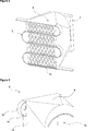
- Figure 3 — is the perspective view of the fan, the air guiding apparatus and the condenser in an embodiment of the present invention.
- Figure 4 – is the perspective view of the fan, the air guiding apparatus and the condenser after the condenser is placed in the air guiding apparatus in an embodiment of the present invention.
- Figure 5 — is the partial perspective view of the air guiding apparatus in an embodiment of the present invention.
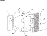
- Figure 6 — is the perspective view of the fan, the air guiding apparatus and the condenser in an embodiment of the present invention.
- the cooling device (1) comprises a compressor (2) providing the compression and circulation of the refrigerant fluid in the refrigeration cycle; a condenser (3) that enables the refrigerant fluid leaving the compressor (2) to change into the liquid phase by condensing, that is formed by bending a pipe in serpentine shape and that has more than one refrigerant tube (4) extending parallel to each other, at least one tube bend (5) joining the refrigerant tubes (4) and more than one fin (6) parallel to one another, extending perpendicularly to the refrigerant tube (4); a fan (7) providing the cooling of the condenser (3), and an air guiding apparatus (8) that is disposed between the fan (7) and the compressor (2) and that has a first orifice (16) facing the fan (7) and a second orifice (17) facing the compressor (2).
- the cooling device (1) of the present invention comprises the air guiding apparatus (8) that extends between the first orifice (16) and the second orifice (17) such that the first orifice (16) and the second orifice (17) are surrounded wherein the condenser (3) is disposed on the second orifice (16) and that has at least one wall (18) enabling the air to be guided to the fins (6) and limiting the movement of air such that the air leaving the fan (7) does not exit around the condenser (3) without contacting the fins (6).
- Air intake is realized from the first orifice (16) of the air guiding apparatus (8), positioned between the compressor (2) and the fan (7) and air exit from the second orifice (17) facing the compressor (2).
- the air leaving the fan (7) is enabled to be carried to the condenser (3) and the compressor (2).
- the condenser (3) is placed on the air guiding apparatus (8), the air entering from the fan (7) into the air guiding apparatus (8) is conveyed to the compressor (2) after passing through the condenser (3).
- the condenser (3) is placed on the air guiding apparatus (8), the fins (6) situated on the condenser (3) remain inside the air guiding apparatus (8) and the tube bends (5) of the condenser (3) remain outside the air guiding apparatus (8).
- the air guiding apparatus (8) is enabled to guide the air leaving the fan (7) onto the fins (6), where the heat transfer surface area is largest thereby increasing the efficiency of the condenser (3).
- the air guiding apparatus (8) comprises a wall (18) having,
- the fins (6) situated on the condenser (3) are positioned between the side walls (11) of the air guiding apparatus (8) and the refrigerant tubes (4) are positioned between the upper wall (9) and the bottom wall (10).
- the air guiding apparatus (8) comprises more than one opening (12) wherein the refrigerant tube (4) is disposed.
- the condenser (3) is enabled to be placed into the air guiding apparatus (8).
- At least one opening (12) is positioned on the air guiding apparatus (8) so as to be opposite to each refrigerant tube (4) ( Figure 3 and Figure 6).
- the air guiding apparatus (8) comprises two openings (12), one between the upper wall (9) and the side walls (11) and one between the bottom wall (10) and the side walls (11). While the condenser (3) is being placed into the air guiding apparatus (8), the upper refrigerant tube (4) of the condenser (3) is placed into the opening (12) between the upper wall (9) and the side walls (11), the lower refrigerant tube (4) of the condenser (3) is placed into the opening (12) located between the bottom wall (10) and the side walls (11). Thus, the condenser (3) is placed into the air guiding apparatus (8) such that no gap remains between refrigerant tubes (4) and the upper wall (9) and the bottom wall (10). Thus, the amount of air delivered to the fins (6) is increased ( Figure 6).
- the air guiding apparatus (8) comprises the opening (12) having the depth (W) that is equal or greater than the width of the refrigerant tube (4).
- the air guiding apparatus (8) comprises at least one lug (13) wherein the tube bend (5) is placed.
- the tube bend (5) is placed into the lug (13)
- the fins (6) are positioned inside the air guiding apparatus (8).
- the air guiding apparatus (8) comprises a PCM container (14) that is disposed in the lug (13) and that comprises phase changing material.
- PCM container (14) By means of the PCM container (14), the temperature of the condenser (3) is decreased and the cooling effectiveness is increased.
- the air guiding apparatus (8) comprises at least one protrusion (15) disposed on the bottom wall (10).
- the assembly of the air guiding apparatus (8) to the cooling device (1) is performed by placing the protrusion (15) into a housing situated between the compressor (2) and the fan (7) on base of the cooling device (1) body (2).
- the protrusion (15) By means of the protrusion (15), the first orifice (16) is positioned opposite the fan (7) at the suitable elevation such that the air leaving the fan (7) enters the air guiding apparatus (8).
- the cooling performance of the fan (7) is improved and the efficiency of the refrigeration cycle is increased by enabling almost the entire air directed by the fan (7) to be carried onto fins (6) by means of the air guiding apparatus (8).
Landscapes
- Engineering & Computer Science (AREA)
- Physics & Mathematics (AREA)
- Thermal Sciences (AREA)
- Mechanical Engineering (AREA)
- General Engineering & Computer Science (AREA)
- Geometry (AREA)
- Chemical & Material Sciences (AREA)
- Combustion & Propulsion (AREA)
- Devices That Are Associated With Refrigeration Equipment (AREA)
Abstract
The present invention relates to a cooling device (1) comprising a compressor (2) providing the compression and circulation of the refrigerant fluid in the refrigeration cycle; a condenser (3) that enables the refrigerant fluid leaving the compressor (2) to change into the liquid phase by condensing, that is formed by bending a pipe in serpentine shape and that has more than one refrigerant tube (4) extending parallel to each other, at least one tube bend (5) joining the refrigerant tubes (4) and more than one fin (6) parallel to one another, extending perpendicularly to the refrigerant tube (4); a fan (7) providing the cooling of the condenser (3), and an air guiding apparatus (8) that is disposed between the fan (7) and the compressor (2) and that has a first orifice (16) facing the fan (7) and a second orifice (17) facing the compressor (2).
Description
The present invention relates to a cooling device comprising an air guiding apparatus that enables the air coming from the fan to be carried the condenser.
In the refrigeration cycle realized in cooling devices, for example in refrigerators or freezers, the heat absorbed from the interior of the cooling device is discharged to the outer environment by means of the condenser. In conventional refrigerators, the static type condenser that functions with the natural heat convection principle is preferred and in no-frost refrigerators, the coil type condenser that operates with enforced heat convection principle is preferred. In condensers that operate with forced heat convection principle, the condenser is cooled by means of the fan. In no-frost refrigerators, the compressor and the condenser generally operate in the machine room which is called the cabinet base region and which is situated at the bottom portion of the refrigerator body. The condenser and the compressor are enabled to be cooled by means of a fan situated in the machine room. However, some portion of the air delivered to the condenser by the fan is dispersed to the exterior environment without contacting the condenser. In this situation, the condenser cannot be cooled as required and this causes the efficiency of the refrigeration cycle to be decreased.
In the state of the art International Patent Application No. WO2008040724, a cooling device is disclosed, wherein the air that is received into the machine room by being sucked from the outer environment by means of a fan is delivered onto a condenser casing which is composed of telescopic bodies and wherein the condenser is situated.
In the state of the art United States Patent Document No. US5592829, the fan disposed between the compressor and the coil shaped condenser that sucks the ambient air from over the condenser and directs it onto the compressor.
The aim of the present invention is the realization of a cooling device comprising a condenser which is enabled to be efficiently cooled with the air blown by the fan.
The cooling device realized in order to attain the aim of the present invention, explicated in the first claim and the respective claims thereof, comprises a compressor providing the compression and circulation of the refrigerant fluid in the refrigeration cycle; a condenser that is formed by bending a tube in serpentine shape, that enables the refrigerant fluid leaving the compressor to change into liquid phase by condensing and that has more than one refrigerant tube extending parallel to one another in the vertical plane, at least one tube bend joining the refrigerant ducts and more than one fin parallel to one another and extending perpendicularly to the refrigerant duct; a fan providing the cooling of the condenser and an air guiding apparatus that is disposed between the fan and the compressor.
The cooling device of the present invention comprises the air guiding apparatus that extends between the first orifice and the second orifice such that the first orifice and the second orifice are surrounded wherein the condenser is disposed on the second orifice and that has at least one wall enabling the air to be guided to the fins and limiting the movement of air such that the air coming from the fan does not exit around the condenser without contacting the fins. The air guiding apparatus comprises two open surfaces facing the fan and the compressor. The condenser is disposed on the open surface of the air guiding apparatus facing the compressor and all condenser fins are positioned in the air flow direction conveyed from the air guiding apparatus to the compressor. Accordingly, the air coming from the fan is enabled to be guided onto the fins where the highest heat transfer occurs and the condenser is enabled to be cooled effectively by the heat transfer realized between the air and the fins.
In an embodiment of the present invention, the air guiding apparatus comprises the wall having,
- an upper wall and a bottom wall that limit the movement of air in the vertical direction such that the air exiting the fan does not leave from the upper and lower portions of the condenser without contacting the fins, and
- two side walls that limits the movement of air in the horizontal direction such that the air exiting the fan does not leave from the sides of the condenser without contacting the fins.
The area formed between the upper wall, bottom wall and the side walls on the open surface of the air guiding apparatus facing the fan is smaller than the area formed between the upper wall, bottom wall and the side walls on the surface of the air guiding apparatus facing the compressor. Thus, the entirety of the air exiting the fan is enabled to be dispersed in equal amounts onto the fins.
In another embodiment of the present invention, the air guiding apparatus comprises at least one opening wherein the refrigerant tube is disposed and that enables the condenser to be placed into the air guiding apparatus. When the refrigerant tubes are disposed into the openings, the fins are positioned between the upper and bottom walls of the air guiding apparatus, in a suitable position to receive the air leaving the fan. After the refrigerant tube is disposed in the opening, the condenser is slid and placed into the air guiding apparatus. In this embodiment, the distance between the upper wall and the bottom wall of the air guiding apparatus is equal to the height of the condenser. Accordingly, the condenser is placed into the air guiding apparatus such that there is no gap between the upper wall of the air guiding apparatus and the uppermost refrigerant tube and between the bottom wall of the air guiding apparatus and the lowermost refrigerant tube. Thus, the air leaving the fan is prevented from leaking through the openings between the air guiding apparatus and the condenser without contacting the fins. After the condenser is placed into the air guiding apparatus, the condenser and the air guiding apparatus are mounted together into the cooling device, thus providing ease of assembly.
In another embodiment of the present invention, the air guiding apparatus comprises the opening that is equal or greater in depth to the width of the refrigerant tube. Thus, the condenser can be slid inwards the air guiding apparatus such that the refrigerant tube is entirely seated into the opening. Accordingly, the fins are positioned to remain inside the air guiding apparatus, all the air exiting the fan leaves the air guiding apparatus after sweeping the fins and air is prevented from leaking from the sides of the fins into the outside environment without contacting the fins.
In another embodiment of the present invention, the air guiding apparatus comprises two openings, one between the upper wall and the side walls and one between the bottom wall and the side walls. In this embodiment, openings are positioned on the side walls so as to be opposite to each other at the same elevations. Thus, the condenser can be placed into the air guiding apparatus such that the refrigerant tubes extend parallel to the base of the cooling device.
In another embodiment of the present invention, the air guiding apparatus comprises at least one lug wherein the tube bend is placed. The lug is produced with the same shape and diameter as the tube bend. When the tube bend is properly placed into the lug, the fins are positioned between the side walls of the air guiding apparatus, in suitable position to meet the air leaving the fan, the tube bend of the condenser not having fins thereon is positioned outside the air guiding apparatus so as to remain outside the air flow direction.
In another embodiment of the present invention, the air guiding apparatus comprises a PCM container that is disposed in the lug and that comprises phase changing material. The heat transfer that occurs between the PCM container and the tube bend enables the condenser to be cooled more effectively and to improve the performance of the condenser.
In another embodiment of the present invention, the air guiding apparatus comprises at least one protrusion disposed on the base thereof. After the condenser is placed into the air guiding apparatus, the protrusion is placed into a housing situated in the cooling device body and the assembly of the air guiding apparatus to the cooling device is realized. By means of the protrusion, the air guiding apparatus and the condenser are easily placed into the machine room of the cooling device.
By means of the present invention, in particular by means of the air guiding apparatus, the amount of cooling air delivered from the fan onto the condenser is increased and hence the efficiency of the refrigeration cycle is improved by enabling the condenser to be cooled better. Moreover, by means of the air guiding apparatus, the condenser is enabled to be placed into the cooling device easily and in suitable position.
The cooling device realized in order to attain the aim of the present invention is illustrated in the attached figures, where:
Figure 1 – is the perspective view of a cooling device.
Figure 2 – is the perspective view of the machine room in an embodiment of the present invention.
Figure 3 – is the perspective view of the fan, the air guiding apparatus and the condenser in an embodiment of the present invention.
Figure 4 – is the perspective view of the fan, the air guiding apparatus and the condenser after the condenser is placed in the air guiding apparatus in an embodiment of the present invention.
Figure 5 – is the partial perspective view of the air guiding apparatus in an embodiment of the present invention.
Figure 6 – is the perspective view of the fan, the air guiding apparatus and the condenser in an embodiment of the present invention.
The elements illustrated in the figures are numbered as follows:
- Cooling device
- Compressor
- Condenser
- Refrigerant tube
- Tube bend
- Fin
- Fan
- Air guiding apparatus
- Upper wall
- Bottom wall
- Side wall
- Opening
- Lug
- PCM container
- Protrusion
- First orifice
- Second orifice
- Wall
The cooling device (1) comprises a compressor (2) providing the compression and circulation of the refrigerant fluid in the refrigeration cycle; a condenser (3) that enables the refrigerant fluid leaving the compressor (2) to change into the liquid phase by condensing, that is formed by bending a pipe in serpentine shape and that has more than one refrigerant tube (4) extending parallel to each other, at least one tube bend (5) joining the refrigerant tubes (4) and more than one fin (6) parallel to one another, extending perpendicularly to the refrigerant tube (4); a fan (7) providing the cooling of the condenser (3), and an air guiding apparatus (8) that is disposed between the fan (7) and the compressor (2) and that has a first orifice (16) facing the fan (7) and a second orifice (17) facing the compressor (2).
The cooling device (1) of the present invention comprises the air guiding apparatus (8) that extends between the first orifice (16) and the second orifice (17) such that the first orifice (16) and the second orifice (17) are surrounded wherein the condenser (3) is disposed on the second orifice (16) and that has at least one wall (18) enabling the air to be guided to the fins (6) and limiting the movement of air such that the air leaving the fan (7) does not exit around the condenser (3) without contacting the fins (6).
Air intake is realized from the first orifice (16) of the air guiding apparatus (8), positioned between the compressor (2) and the fan (7) and air exit from the second orifice (17) facing the compressor (2). Thus, the air leaving the fan (7) is enabled to be carried to the condenser (3) and the compressor (2). When the condenser (3) is placed on the air guiding apparatus (8), the air entering from the fan (7) into the air guiding apparatus (8) is conveyed to the compressor (2) after passing through the condenser (3). When the condenser (3) is placed on the air guiding apparatus (8), the fins (6) situated on the condenser (3) remain inside the air guiding apparatus (8) and the tube bends (5) of the condenser (3) remain outside the air guiding apparatus (8). Accordingly, the air guiding apparatus (8) is enabled to guide the air leaving the fan (7) onto the fins (6), where the heat transfer surface area is largest thereby increasing the efficiency of the condenser (3).
In an embodiment of the present invention, the air guiding apparatus (8) comprises a wall (18) having,
- an upper wall (9) and a bottom wall (10) that limit the movement of air in the vertical direction such that the air exiting the fan (7) does not leave from the upper and lower portions of the condenser (3) without contacting the fins (6), and
- two side walls (11) that limit the movement of air in the horizontal direction such that the air exiting the fan (7) does not leave from the sides of the condenser (3) without contacting the fins (6).
When the condenser (3) is placed on the air guiding apparatus (8), the fins (6) situated on the condenser (3) are positioned between the side walls (11) of the air guiding apparatus (8) and the refrigerant tubes (4) are positioned between the upper wall (9) and the bottom wall (10).
In another embodiment of the present invention, the air guiding apparatus (8) comprises more than one opening (12) wherein the refrigerant tube (4) is disposed. By disposing the refrigerant tube (4) in the opening (12), the condenser (3) is enabled to be placed into the air guiding apparatus (8). At least one opening (12) is positioned on the air guiding apparatus (8) so as to be opposite to each refrigerant tube (4) (Figure 3 and Figure 6).
In another embodiment of the present invention, the air guiding apparatus (8) comprises two openings (12), one between the upper wall (9) and the side walls (11) and one between the bottom wall (10) and the side walls (11). While the condenser (3) is being placed into the air guiding apparatus (8), the upper refrigerant tube (4) of the condenser (3) is placed into the opening (12) between the upper wall (9) and the side walls (11), the lower refrigerant tube (4) of the condenser (3) is placed into the opening (12) located between the bottom wall (10) and the side walls (11). Thus, the condenser (3) is placed into the air guiding apparatus (8) such that no gap remains between refrigerant tubes (4) and the upper wall (9) and the bottom wall (10). Thus, the amount of air delivered to the fins (6) is increased (Figure 6).
In another embodiment of the present invention, the air guiding apparatus (8) comprises the opening (12) having the depth (W) that is equal or greater than the width of the refrigerant tube (4). Thus, when the refrigerant tube (4) is placed into the opening (12), the condenser (3) is positioned so as to remain in the air guiding apparatus (8) and the entire air leaving the fan (7) is enabled to be passed over the fins (6) without dispersing to the outside environment. Moreover, by means of the condenser (3) remaining inside the air guiding apparatus (8), the volume occupied by the condenser (3) in the machine room is decreased.
In another embodiment of the present invention, the air guiding apparatus (8) comprises at least one lug (13) wherein the tube bend (5) is placed. When the tube bend (5) is placed into the lug (13), the fins (6) are positioned inside the air guiding apparatus (8). By placing the tube bend (5) in the lug (13) situated on the outer surface of the air guiding apparatus (8), the air leaving the fan (7) is prevented from being delivered to the tube bend (5). Thus, the entire air leaving the fan (7) can be passed over the fins (6).
In another embodiment of the present invention, the air guiding apparatus (8) comprises a PCM container (14) that is disposed in the lug (13) and that comprises phase changing material. By means of the PCM container (14), the temperature of the condenser (3) is decreased and the cooling effectiveness is increased.
In another embodiment of the present invention, the air guiding apparatus (8) comprises at least one protrusion (15) disposed on the bottom wall (10). The assembly of the air guiding apparatus (8) to the cooling device (1) is performed by placing the protrusion (15) into a housing situated between the compressor (2) and the fan (7) on base of the cooling device (1) body (2). By means of the protrusion (15), the first orifice (16) is positioned opposite the fan (7) at the suitable elevation such that the air leaving the fan (7) enters the air guiding apparatus (8).
In the cooling device (1) of the present invention, the cooling performance of the fan (7) is improved and the efficiency of the refrigeration cycle is increased by enabling almost the entire air directed by the fan (7) to be carried onto fins (6) by means of the air guiding apparatus (8).
Claims (8)
- A cooling device (1) comprising a compressor (2) providing the compression and circulation of the refrigerant fluid in the refrigeration cycle; a condenser (3) that enables the refrigerant fluid leaving the compressor (2) to change into the liquid phase by condensing, that is formed by bending a pipe in serpentine shape and that has more than one refrigerant tube (4) extending parallel to each other, at least one tube bend (5) joining the refrigerant tubes (4) and more than one fin (6) parallel to one another, extending perpendicularly to the refrigerant tube (4); a fan (7) providing the cooling of the condenser (3), and an air guiding apparatus (8) that is disposed between the fan (7) and the compressor (2) and that has a first orifice (16) facing the fan (7) and a second orifice (17) facing the compressor (2), characterized by the air guiding apparatus (8)- wherein the condenser (3) is placed on the second orifice (16), and- that extends between the first orifice (16) and the second orifice (17) such that the first orifice (16) and the second orifice (17) are surrounded and that has at least one wall (18) enabling the air to be guided to the fins (6) and limiting the movement of air such that the air leaving the fan (7) does not exit around the condenser (3) without contacting the fins (6).
- A cooling device (1) as in Claim 1, characterized by the air guiding apparatus (8) comprising the wall (18) having- an upper wall (9) and a bottom wall (10) that limit the movement of air in the vertical direction such that the air exiting the fan (7) does not leave from the upper and lower portions of the condenser (3) without contacting the fins (6), and- two side walls (11) that limit the movement of air in the horizontal direction such that the air exiting the fan (7) does not leave from the sides of the condenser (3) without contacting the fins (6).
- A cooling device (1) as in any one of the above claims, characterized by the air guiding apparatus (8) comprising more than one opening (12) wherein the refrigerant tube (4) is disposed.
- A cooling device (1) as in Claim 3, characterized by the air guiding apparatus (8) comprising two openings (12), one between the upper wall (9) and the side walls (11) and one between the bottom wall (10) and the side walls (11).
- A cooling device (1) as in Claim 2, characterized by the air guiding apparatus (8) comprising the opening (12) having the depth (W) that is equal or greater than the width of the refrigerant tube (4).
- A cooling device (1) as in any one of the above claims, characterized by the air guiding apparatus (8) comprising at least one lug (13) extending outwards from the side walls (11) and wherein the tube bend (5) is disposed.
- A cooling device (1) as in Claim 6, characterized by the air guiding apparatus (8) having a PCM container (14) that is disposed in the lug (13) and that comprises phase changing material.
- A cooling device (1) as in Claim 1, characterized by the air guiding apparatus (8) comprising at least one protrusion (15) disposed on the bottom wall (10).
Applications Claiming Priority (2)
| Application Number | Priority Date | Filing Date | Title |
|---|---|---|---|
| TRA2015/05518 | 2015-05-07 | ||
| TR201505518 | 2015-05-07 |
Publications (1)
| Publication Number | Publication Date |
|---|---|
| WO2016177803A1 true WO2016177803A1 (en) | 2016-11-10 |
Family
ID=55910279
Family Applications (1)
| Application Number | Title | Priority Date | Filing Date |
|---|---|---|---|
| PCT/EP2016/060043 Ceased WO2016177803A1 (en) | 2015-05-07 | 2016-05-04 | A cooling device comprising a condenser cooled by a fan |
Country Status (1)
| Country | Link |
|---|---|
| WO (1) | WO2016177803A1 (en) |
Cited By (5)
| Publication number | Priority date | Publication date | Assignee | Title |
|---|---|---|---|---|
| DE102017003481A1 (en) | 2017-01-23 | 2018-07-26 | Liebherr-Hausgeräte Ochsenhausen GmbH | Fridge and / or freezer |
| EP3686518A4 (en) * | 2017-09-19 | 2021-06-23 | LG Electronics Inc. | CONDENSER FOR REFRIGERATOR |
| WO2022119520A1 (en) * | 2020-12-04 | 2022-06-09 | Oenal Talat Semih | A refrigerator comprising a stepped platform and air diffuser plate to perform efficient refrigeration |
| CN114992964A (en) * | 2022-06-28 | 2022-09-02 | Tcl家用电器(合肥)有限公司 | Heat radiation structure and refrigerator |
| EP4332476A1 (en) * | 2022-08-29 | 2024-03-06 | BSH Hausgeräte GmbH | Refrigeration device and heat exchanger assembly for a refrigeration device |
Citations (4)
| Publication number | Priority date | Publication date | Assignee | Title |
|---|---|---|---|---|
| KR20030077211A (en) * | 2002-03-25 | 2003-10-01 | 위니아만도 주식회사 | Shroud structure for kimchi-storage |
| DE102011007415A1 (en) * | 2011-04-14 | 2012-10-18 | BSH Bosch und Siemens Hausgeräte GmbH | Evaporation device for a refrigeration device |
| WO2013165535A1 (en) * | 2012-05-03 | 2013-11-07 | Carrier Corporation | Air conditioning system having supercooled phase change material |
| WO2015043676A1 (en) * | 2013-09-30 | 2015-04-02 | Arcelik Anonim Sirketi | Forced convection heat exchanger for a refrigeration appliance |
-
2016
- 2016-05-04 WO PCT/EP2016/060043 patent/WO2016177803A1/en not_active Ceased
Patent Citations (4)
| Publication number | Priority date | Publication date | Assignee | Title |
|---|---|---|---|---|
| KR20030077211A (en) * | 2002-03-25 | 2003-10-01 | 위니아만도 주식회사 | Shroud structure for kimchi-storage |
| DE102011007415A1 (en) * | 2011-04-14 | 2012-10-18 | BSH Bosch und Siemens Hausgeräte GmbH | Evaporation device for a refrigeration device |
| WO2013165535A1 (en) * | 2012-05-03 | 2013-11-07 | Carrier Corporation | Air conditioning system having supercooled phase change material |
| WO2015043676A1 (en) * | 2013-09-30 | 2015-04-02 | Arcelik Anonim Sirketi | Forced convection heat exchanger for a refrigeration appliance |
Cited By (7)
| Publication number | Priority date | Publication date | Assignee | Title |
|---|---|---|---|---|
| DE102017003481A1 (en) | 2017-01-23 | 2018-07-26 | Liebherr-Hausgeräte Ochsenhausen GmbH | Fridge and / or freezer |
| EP3686518A4 (en) * | 2017-09-19 | 2021-06-23 | LG Electronics Inc. | CONDENSER FOR REFRIGERATOR |
| US11592222B2 (en) | 2017-09-19 | 2023-02-28 | Lg Electronics Inc. | Condenser for refrigerator |
| WO2022119520A1 (en) * | 2020-12-04 | 2022-06-09 | Oenal Talat Semih | A refrigerator comprising a stepped platform and air diffuser plate to perform efficient refrigeration |
| CN114992964A (en) * | 2022-06-28 | 2022-09-02 | Tcl家用电器(合肥)有限公司 | Heat radiation structure and refrigerator |
| CN114992964B (en) * | 2022-06-28 | 2024-04-02 | Tcl家用电器(合肥)有限公司 | Heat dissipation structure and refrigerator |
| EP4332476A1 (en) * | 2022-08-29 | 2024-03-06 | BSH Hausgeräte GmbH | Refrigeration device and heat exchanger assembly for a refrigeration device |
Similar Documents
| Publication | Publication Date | Title |
|---|---|---|
| US11940162B2 (en) | Integrated air conditioner | |
| JP6740057B2 (en) | refrigerator | |
| US9328965B2 (en) | Heat exchanger of air conditioning device including a refrigerant path arranged downstream of other refrigerant paths relative to airflow direction | |
| KR20090006418A (en) | Refrigerator | |
| EP2410267B1 (en) | Refrigerator | |
| JP5405158B2 (en) | Evaporator | |
| EP2938945A1 (en) | A defrost water evaporation tray, a condenser retainer and a cooling device wherein the same are used | |
| KR20190050652A (en) | Air Conditioner | |
| JP2011027293A (en) | Oil separator | |
| WO2016107687A1 (en) | A cooling device comprising an air guiding apparatus | |
| JP7412446B2 (en) | refrigerator | |
| KR20110087917A (en) | Refrigerator | |
| KR20200004216A (en) | Evaporator and refrigerator having the same | |
| CN115854626A (en) | freezer | |
| JP6850091B2 (en) | refrigerator | |
| KR20220012109A (en) | Refrigerator | |
| US7730742B2 (en) | Accelerated heat exchanger | |
| KR20130031638A (en) | An air conditioner | |
| KR20140058911A (en) | Defrost heater arrangement structure | |
| KR20170024883A (en) | Refrigerator | |
| JP5624365B2 (en) | refrigerator | |
| KR100512106B1 (en) | The refrigerator for improvement on heat exchange efficiency | |
| WO2017188146A1 (en) | Refrigerator | |
| KR20150056318A (en) | Heat exchanger and refrigerator having the same | |
| JP5553101B2 (en) | Cooler and cooler |
Legal Events
| Date | Code | Title | Description |
|---|---|---|---|
| 121 | Ep: the epo has been informed by wipo that ep was designated in this application |
Ref document number: 16720154 Country of ref document: EP Kind code of ref document: A1 |
|
| NENP | Non-entry into the national phase |
Ref country code: DE |
|
| 122 | Ep: pct application non-entry in european phase |
Ref document number: 16720154 Country of ref document: EP Kind code of ref document: A1 |