WO2016171476A1 - 동맥 혈압 파형의 특징점을 이용한 두개내압 파형의 피크 검출 장치 및 방법 - Google Patents
동맥 혈압 파형의 특징점을 이용한 두개내압 파형의 피크 검출 장치 및 방법 Download PDFInfo
- Publication number
- WO2016171476A1 WO2016171476A1 PCT/KR2016/004132 KR2016004132W WO2016171476A1 WO 2016171476 A1 WO2016171476 A1 WO 2016171476A1 KR 2016004132 W KR2016004132 W KR 2016004132W WO 2016171476 A1 WO2016171476 A1 WO 2016171476A1
- Authority
- WO
- WIPO (PCT)
- Prior art keywords
- waveform
- intracranial
- pressure waveform
- intracranial pressure
- peak
- Prior art date
- Legal status (The legal status is an assumption and is not a legal conclusion. Google has not performed a legal analysis and makes no representation as to the accuracy of the status listed.)
- Ceased
Links
Images



Classifications
-
- A—HUMAN NECESSITIES
- A61—MEDICAL OR VETERINARY SCIENCE; HYGIENE
- A61B—DIAGNOSIS; SURGERY; IDENTIFICATION
- A61B5/00—Measuring for diagnostic purposes; Identification of persons
- A61B5/03—Measuring fluid pressure within the body other than blood pressure, e.g. cerebral pressure ; Measuring pressure in body tissues or organs
- A61B5/031—Intracranial pressure
-
- A—HUMAN NECESSITIES
- A61—MEDICAL OR VETERINARY SCIENCE; HYGIENE
- A61B—DIAGNOSIS; SURGERY; IDENTIFICATION
- A61B5/00—Measuring for diagnostic purposes; Identification of persons
- A61B5/02—Detecting, measuring or recording for evaluating the cardiovascular system, e.g. pulse, heart rate, blood pressure or blood flow
- A61B5/0205—Simultaneously evaluating both cardiovascular conditions and different types of body conditions, e.g. heart and respiratory condition
-
- A—HUMAN NECESSITIES
- A61—MEDICAL OR VETERINARY SCIENCE; HYGIENE
- A61B—DIAGNOSIS; SURGERY; IDENTIFICATION
- A61B5/00—Measuring for diagnostic purposes; Identification of persons
- A61B5/02—Detecting, measuring or recording for evaluating the cardiovascular system, e.g. pulse, heart rate, blood pressure or blood flow
- A61B5/021—Measuring pressure in heart or blood vessels
-
- A—HUMAN NECESSITIES
- A61—MEDICAL OR VETERINARY SCIENCE; HYGIENE
- A61B—DIAGNOSIS; SURGERY; IDENTIFICATION
- A61B5/00—Measuring for diagnostic purposes; Identification of persons
- A61B5/02—Detecting, measuring or recording for evaluating the cardiovascular system, e.g. pulse, heart rate, blood pressure or blood flow
- A61B5/024—Measuring pulse rate or heart rate
-
- A—HUMAN NECESSITIES
- A61—MEDICAL OR VETERINARY SCIENCE; HYGIENE
- A61B—DIAGNOSIS; SURGERY; IDENTIFICATION
- A61B5/00—Measuring for diagnostic purposes; Identification of persons
- A61B5/74—Details of notification to user or communication with user or patient; User input means
- A61B5/742—Details of notification to user or communication with user or patient; User input means using visual displays
- A61B5/7425—Displaying combinations of multiple images regardless of image source, e.g. displaying a reference anatomical image with a live image
-
- A—HUMAN NECESSITIES
- A61—MEDICAL OR VETERINARY SCIENCE; HYGIENE
- A61B—DIAGNOSIS; SURGERY; IDENTIFICATION
- A61B5/00—Measuring for diagnostic purposes; Identification of persons
- A61B5/74—Details of notification to user or communication with user or patient; User input means
- A61B5/742—Details of notification to user or communication with user or patient; User input means using visual displays
- A61B5/743—Displaying an image simultaneously with additional graphical information, e.g. symbols, charts, function plots
-
- A—HUMAN NECESSITIES
- A61—MEDICAL OR VETERINARY SCIENCE; HYGIENE
- A61B—DIAGNOSIS; SURGERY; IDENTIFICATION
- A61B5/00—Measuring for diagnostic purposes; Identification of persons
- A61B5/48—Other medical applications
- A61B5/4842—Monitoring progression or stage of a disease
-
- A—HUMAN NECESSITIES
- A61—MEDICAL OR VETERINARY SCIENCE; HYGIENE
- A61B—DIAGNOSIS; SURGERY; IDENTIFICATION
- A61B5/00—Measuring for diagnostic purposes; Identification of persons
- A61B5/72—Signal processing specially adapted for physiological signals or for diagnostic purposes
- A61B5/7271—Specific aspects of physiological measurement analysis
- A61B5/7278—Artificial waveform generation or derivation, e.g. synthesizing signals from measured signals
-
- G—PHYSICS
- G06—COMPUTING OR CALCULATING; COUNTING
- G06F—ELECTRIC DIGITAL DATA PROCESSING
- G06F2218/00—Aspects of pattern recognition specially adapted for signal processing
- G06F2218/12—Classification; Matching
- G06F2218/14—Classification; Matching by matching peak patterns
Definitions
- the present invention relates to an apparatus and method for detecting peaks of intracranial pressure using characteristic points of arterial blood pressure waveforms.
- ICP intracranial pressure
- the intracranial pressure waveform has harmonics such as heart rate, respiratory cycle and indirectly reflects information about the cerebrovascular system.
- the three main peaks in the intracranial pressure waveform are named P1, P2, and P3, each with a different physiological origin.
- features such as the amplitude of the three peaks and the troughs present between them, and the time delay from the pulse onset to the peak, are characterized by intracranial compliance. Or state about cerebral autoregulation. Therefore, it is very important to accurately recognize and interpret this.
- MOCAIP a conventional technique, utilizes a reference pulse library that collects data extracted from several patients in order to detect peaks of intracranial pressure waveforms.
- the reference pulse library contains the information of various internal voltage waveforms.
- the MOCAIP technology uses this inherent information to improve the accuracy of peak detection.
- the shape of intracranial pressure waveform shows various aspects, and therefore, the waveform that can be referred to for peak detection depends on the nature of the data to be analyzed.
- the prior art requires an extensive reference pulse library of various patient cases. This reduces efficiency in offline environments where reference pulse libraries are not available.
- the prior art detects peaks in intracranial withstand pulses that are averaged to individual pulses of recorded intracranial withstand waveforms as a way to reduce signal defects or noise.
- the averaged intracranial pressure pulses do not capture the characteristics of individual pulses that vary in real time. Therefore, the clinical use of the prior art may be limited.
- the present invention is to solve the above-mentioned problems of the prior art, and to provide a method for automatically detecting P1, P2 and P3 peaks from a continuous intracranial pressure waveform.
- a method for detecting peaks in intracranial withstand waveforms with high accuracy is provided without a reference pulse library.
- the peak detection method of the intracranial pressure waveform using the characteristic point of the arterial blood pressure waveform is a waveform in the continuous intracranial pressure waveform based on the contraction peak of the arterial blood pressure waveform Detecting a starting point of the; Distinguishing each intracranial voltage waveform in a continuous intracranial pressure waveform based on a start point of the waveform; Deriving a derivative value from each intracranial pressure waveform to detect peaks, valleys, and flats; Calculating a time delay from the starting point of the detected waveform to the detected peak in each intracranial voltage waveform and clustering peaks having similar values to generate a peak cluster; Searching for a pulse patch in each intracranial pressure waveform based on a time delay value of the overlapping pulse patch of the arterial blood pressure waveform; Detecting P1, P2, and P3 peaks in each intracranial voltage waveform with reference to the detected pulse duration of the intracranial pressure.
- the peak detection device of the intracranial pressure waveform using the characteristic point of the arterial blood pressure waveform is processing arranged to interface with the memory portion in which the peak detection application of the intracranial pressure waveform, and the peak detection application of the intracranial pressure waveform It includes a unit.
- the processing unit receives the arterial blood pressure waveform and the intracranial pressure waveform from the sensor unit according to the execution of the peak detection application of the intracranial pressure waveform.
- the received arterial blood pressure waveform signal and intracranial pressure waveform signal are converted into digital data and stored in the memory unit.
- the starting point of the waveform is detected in the continuous intracranial pressure waveform based on the contraction peak of the arterial blood pressure waveform.
- each of the intracranial pressure waveforms is divided in successive intracranial pressure waveforms, and a derivative value is derived from each of the intracranial pressure waveforms to detect peaks, valleys, and flats.
- the time delay of the detected peak is then calculated from the starting point of the detected waveform in each intracranial breakdown waveform.
- peak peaks are generated by clustering peaks having similar time intervals, and the pulse cavities are searched in the respective intracranial pressure waveforms based on time delay values of the overlapping pulse cavities of the arterial blood pressure waveforms.
- the P1, P2, and P3 peaks are then detected in each intracranial voltage waveform with reference to the searched pulse duration of the intracranial pressure.
- any one of the above problem solving means of the present invention by automatically detecting the three peaks in the intracranial pressure waveform, it is possible to monitor the continuous intracranial pressure waveform.
- Figure 1 schematically shows a peak detection apparatus of intracranial pressure waveform using the characteristic points of the arterial blood pressure waveform in accordance with an embodiment of the present invention.
- Figure 2 shows three peaks of the intracranial breakdown voltage contemplated in one embodiment of the present invention.
- Figure 3 is a flow chart for explaining in detail the peak detection method of intracranial pressure waveform using the characteristic point of the arterial blood pressure waveform in accordance with an embodiment of the present invention.
- FIG. 4 is a flowchart for explaining in detail the step of detecting the starting point of the waveform in the continuous intracranial withstand voltage waveform according to an embodiment of the present invention.
- FIG. 5 is a flow chart illustrating in detail the steps of detecting peaks, valleys, and flats in each intracranial pressure waveform according to an embodiment of the present invention.
- FIG. 6 is a flowchart for describing in detail a step of calculating time delays of peaks detected in each intracranial pressure waveform according to an embodiment of the present invention and grouping peaks having similar time delay values into clusters.
- Figure 7 shows an embodiment of the peak detection method of intracranial pressure waveform using the characteristic point of the arterial blood pressure waveform according to an embodiment of the present invention.
- FIG. 8 illustrates another embodiment of peak detection of the intracranial pressure waveform using feature points of the arterial blood pressure waveform according to an embodiment of the present invention.
- FIG 9 shows the results of verifying the accuracy of the peak detection of the intracranial pressure waveform using the feature points of the arterial blood pressure waveform according to an embodiment of the present invention.
- Figure 1 schematically shows a peak detection apparatus of intracranial pressure waveform using the characteristic points of the arterial blood pressure waveform in accordance with an embodiment of the present invention.
- an apparatus for detecting peaks of intracranial pressure waveform using feature points of an arterial blood pressure waveform includes a sensor unit 100, a memory 200, a processing unit 300, and a display 400. ).
- the sensor unit 100 and the display unit 400 are included in the peak detection device of the intracranial pressure waveform using the feature points of the arterial blood pressure waveform according to an embodiment of the present invention or outside the feature point detection device of the arterial blood pressure waveform. It can be provided separately.
- the sensor unit 100 may include an analog amplifier (not shown), a digital converter (not shown), and the like, and measure and convert arterial blood pressure or intracranial pressure into a digital signal.
- the memory 200 may store peak detection applications of intracranial pressure waveforms, and store arterial blood pressure waveform data and intracranial pressure waveform data converted into digital signals.
- memory 200 includes both volatile and nonvolatile, removable and non-removable media implemented in any method or technology for storage of information such as computer readable instructions, data structures, program modules or other data.
- the memory 200 may include a read only memory (ROM), a random access memory (RAM), a magnetic tape, a magnetic disk, a flash memory, an optical data storage device, a compact flash (CF) card, and a secure SD.
- ROM read only memory
- RAM random access memory
- magnetic tape a magnetic tape
- magnetic disk a magnetic disk
- flash memory an optical data storage device
- CF compact flash
- secure SD Secure Digital
- NAND flash memory hard disk drives (HDD), such as digital cards, memory sticks, solid-state drives (SSDs) and micro SD cards Magnetic computer storage such as the like and the like.
- HDD hard disk drives
- SSDs solid-state drives
- the processing unit 300 detects the characteristic points of the arterial blood pressure waveform by deriving derivative values from the arterial blood pressure waveform data and the intracranial pressure waveform data stored in the memory 200 according to the execution of the peak detection application of the intracranial pressure waveform. Three peaks are detected at.
- the display 400 may display in real time three peaks on the intracranial withstand voltage waveform measured by the sensor unit 100 and the intracranial withstand voltage waveform detected by the processing unit 300. In addition, it is possible to colorize and display the point where each peak is located.
- Figure 2 shows three peaks of the intracranial breakdown voltage contemplated in one embodiment of the present invention.
- the intracranial breakdown voltage considered in one embodiment of the present invention includes three sub pulses of P1, P2, and P3.
- the floor of each pulse is defined as P1 peak, P2 peak, and P3 peak in the order of appearance in the waveform.
- Three peaks of these intracranial pressure waveforms contain information about intracranial compliance and cerebral vasculature.
- the P1 pulse is the first pressure wave that appears when the choroid plexus beats during the systole of the heart and is called a percussion wave.
- the P2 pulses appearing after the P1 pulses are generated by the rebound phenomenon of the veins.
- the amplitude of P2 peak is smaller than that of P1 peak as energy generated by recoil of veins is absorbed under normal circumstances.
- the recoil increases and the amplitude of P2 peaks increases, sometimes even greater than P1 peaks.
- a reversal phenomenon in which the amplitude of this P2 peak is greater than the amplitude of the P1 peak indicates a decrease in intracranial compliance.
- the aortic valve is closed, and the pulse concavity appears in the intracranial pressure waveform at the same time point as when a duplicate pulse notch is observed in the arterial blood pressure waveform. Therefore, the P3 pulse occurs as the ventricle enters the diastolic phase after the pulse depression appears in the waveform of intracranial pressure.
- the waveform of intracranial pressure is also changed by the vibration of the blood flow.
- the waveform of intracranial pressure is correlated with the waveform of arterial blood pressure, because the brain blood volume is changed by the heartbeat, which causes the brain pressure to change.
- understanding the range of blood pressure and perfusion pressure that can be used to determine whether auto-regulation is maintained in patients with brain injury is very important in determining treatment goals for patients with brain injury.
- information about arterial blood pressure and cerebral blood flow should be available, but it is not easy to obtain continuous brain blood flow information.
- patients who have lost their autoregulatory function have elevated cerebral blood flow as soon as their blood pressure rises, leading to a direct increase in brain pressure.
- the peak detecting device of the intracranial pressure waveform using the characteristic point of the arterial blood pressure waveform automatically searches for three P1, P2, and P3 waveforms from the intracranial pressure waveform, It provides a method for calculating information about the time delay and the amplitude of the waveform.
- Figure 3 is a flow chart for explaining in detail the peak detection method of intracranial pressure waveform using the characteristic point of the arterial blood pressure waveform in accordance with an embodiment of the present invention.
- the peak detection method of the intracranial pressure waveform using the characteristic points of the arterial blood pressure waveform includes: detecting a starting point of the waveform in a continuous intracranial pressure waveform; Dividing the respective intracranial withstand voltage waveforms in a continuous intracranial withstand voltage waveform (s200); Detecting a peak, a valley, and a flat in each intracranial pressure waveform (s300); Generating a peak cluster by clustering peaks having similar time intervals by calculating time delays of the peaks detected in each intracranial pressure waveform; Searching for a pulse pit in each intracranial pressure waveform (s500); Arranging the peak clusters in ascending or descending order (s600) and detecting the peaks P1, P2 and P3 in the intracranial pressure waveform (s700).
- the processing unit 300 detects the start point of the waveform in the continuous intracranial pressure waveform based on search information of the contraction peak of the arterial blood pressure waveform. .
- FIG. 4 is a flowchart for explaining in detail the step of detecting the starting point of the waveform in the continuous intracranial withstand voltage waveform according to an embodiment of the present invention.
- the detecting of the starting point of the waveform in the continuous intracranial pressure waveform includes: detecting a contraction peak in the arterial blood pressure waveform (S110); Detecting a starting point of the waveform in the arterial blood pressure waveform (s120); And detecting a starting point of the waveform in the intracranial withstand voltage waveform (s130).
- step S110 of detecting a contraction peak in the arterial blood pressure waveform the processing unit 300 derives the derivative value from the arterial blood pressure waveform, and the arterial blood pressure waveform for an arbitrary time at the beginning of the analysis. Calculate the maximum and average of. Then, peaks exceeding the calculated average value and close to the maximum value are collected in a time window. At this time, the collected peak is when the j th point of the arterial blood pressure waveform is A j and the pressure value is P A, j , where P A, j ⁇ 1 ⁇ P A, j at the same time P A, j > It may be a point satisfying P A, j + 1 .
- the length of the time window depends on the arbitrary time of analyzing the maximum value and the average value. For example, if you have collected the peaks and averages from a waveform that exists within three seconds and then collected candidates for shrinkage peaks, the length of the time window ranges from a minimum of three seconds to a maximum of thirty seconds as the candidates for the collected shrinkage peaks increase. Can have
- the processing unit 300 calculates an average time gap mean ⁇ j and an average pressure value mean P j of the peaks collected in the time window.
- the time gaps ⁇ A and j represent time gaps with the immediately preceding peak with respect to the j-th peak collected in the time window.
- the processing unit 300 detects a systolic peak based on the average time gap mean ⁇ j and the average pressure value mean P j obtained in the time window.
- the contraction peak is selected from the candidates of the contraction peak extracted in the time window,
- ⁇ mean ⁇ A , j J-th peaks satisfying 0.15 may be selected as a systolic peak.
- step S120 of detecting the starting point of the waveform in the arterial blood pressure waveform the processing unit 300 changes the bone points that appear before the maximum slope of the derivative, that is, just before the contraction peak 20, to the starting point of the waveform. Detect.
- step S130 of detecting the starting point of the waveform in the intracranial pressure waveform the processing unit 300 detects the starting point of the waveform in the continuous intracranial pressure waveform based on the search information of the contraction peak of the arterial blood pressure waveform.
- the processing unit 300 when the contraction peak measurement time of the arterial blood pressure waveform is ⁇ A, j , the processing unit 300 is intracranial pressure waveform present between ⁇ A, j and ⁇ A, j +1 and it calculates the value of the pressure P I, P I j of Min min and a maximum value P max and the mean value I mean I P. Then, ⁇ A, j from the measurement time of the intracranial pressure waveform at the point where max P I was measured. When searching in reverse chronological order, the valley I k of the intracranial pressure waveform satisfying Equation 1 Is detected as the starting point of the intracranial pressure waveform.
- the processing unit 300 detects after detecting the start point of the waveform in the intracranial pressure waveform.
- Each of the two breakdown voltage waveforms is distinguished from the continuous breakdown voltage waveform using the starting point of the waveform (s200). That is, the processing unit 300 distinguishes the waveform divided into the start point of the waveform detected in step S100 and the start point of the next waveform, respectively.
- n represents the last waveform in the arterial blood pressure waveform and the intracranial pressure waveform.
- the peak detection method of the intracranial pressure waveform using the characteristic point of the arterial blood pressure waveform M i
- the number of data in the data can be linearly interpolated to 64.
- the i th waveform M i The data present in can be described as a two-dimensional point, it can be expressed as shown in Equation 2 below.
- t i, j represents the time domain and f (t i, j ) represents the pressure domain.
- the peak detection method of the intracranial pressure waveform using the characteristic point of the arterial blood pressure waveform according to an embodiment of the present invention after the step of distinguishing each intracranial pressure waveform in the continuous intracranial pressure waveform waveform having a starting point of the inappropriate waveform may further include filtering.
- the step of filtering a waveform having a starting point of an improper waveform is specifically t i, 64
- the cardiac cycle, calculated by the value of t i, j can be used.
- the heart rate period average (MCC) of the three previous waveforms and the three subsequent waveforms is calculated for each waveform, and waveforms having a heart rate period outside the range of ⁇ MCC * 0.15 are considered inappropriate. Can be excluded.
- MCC heart rate period average
- the low pass filter may be 10 Hz, but is not limited thereto.
- the peak detection method of the intracranial pressure waveform using the characteristic points of the arterial blood pressure waveform detects peaks, valleys, and flats in each intracranial pressure waveform (S300).
- the flat here is not a peak in the intracranial pressure waveform, but represents a point where the waveform becomes flat or the degree to which the pressure value decreases or increases is small.
- FIG. 5 is a flow chart illustrating in detail the steps of detecting peaks, valleys, and flats in each intracranial pressure waveform according to an embodiment of the present invention.
- detecting peaks, valleys, and flats in each intracranial pressure waveform may include normalizing data of the intracranial pressure waveform (s310); Deriving a derivative value from the normalized intracranial pressure waveform (s320); And detecting peaks, valleys, and flats based on the derivative value (s330).
- M i M i
- ⁇ i, j ⁇ i, j , f ( ⁇ i, j ) ⁇ through normalization, ⁇ i, j and f ( ⁇ i, j ) are the same as Equations 3 and 4, respectively.
- the above-described method using the central difference method requires two data values that exist before and two data values that exist afterward to derive a derivative value for one data value. Therefore, when two or more pieces of data do not exist before and after, a derivative value may be derived using Equation 6.
- the processing unit 300 performs f ' ( ⁇ i, j simultaneously with f ′ ( ⁇ i, j ⁇ 1 )> 0. If f ⁇ i, j-1 ) ⁇ f ( ⁇ i, j ), ⁇ i, j is detected as a peak, and f ( ⁇ i, j -1 )> f ( ⁇ ). i, j ), ⁇ i, j - 1 is detected as a peak.
- the processing unit 300 is ⁇ i, j -3 from ⁇ i, j, not the peak or ridge all seven dots to +3
- ⁇ i, j is detected as a flat.
- the flat may be continuously set at several points.
- detecting peaks, valleys, and flats in the intracranial pressure waveform detects major points such as peaks, valleys, and flats for all points of the normalized intracranial pressure waveform. If, ⁇ i, j is detected as a major point which is one of peak, valley and flat, then the data point x i, j before normalization corresponding to the detected major point is also detected as the major point.
- the arterial blood pressure waveform may include detecting the main points such as peaks, bones, and flats. Can be. Therefore, according to the method described above, all the major points can be detected in the data of the arterial blood pressure waveform and the intracranial pressure waveform.
- step S400 the peak delays of the peaks detected in the intracranial breakdown voltage waveforms are calculated and the peaks having similar values are clustered to generate a peak cluster (S400).
- FIG. 6 is a flowchart illustrating a detailed step (s400) of generating a peak cluster by clustering peaks having similar time delay values by calculating time delays of peaks detected in respective intracranial pressure waveforms according to an embodiment of the present invention. to be.
- step S400 of generating peak clusters by calculating time delays of peaks detected in the intracranial pressure waveform and clustering peaks having similar time delay values initializing a cluster using a time delay value ( s410); Clustering peaks having similar time delay values to generate a peak cluster (s420); And redistributing the peak to the cluster having the minimum distance value (s430).
- step S410 of initializing a cluster using a time delay value the processing unit 300 calculates a distance between the most recent element x i, j input to the k th cluster C k .
- the distance D k (x i, j ) between the most recent elements x i, j input to the k-th cluster C k may be calculated by Equation 7 below.
- L (x i, j ) represents the time interval from the start point of the waveform to x i, j can be calculated by Equation 8.
- L (y k, p ) represents the time interval of the last element included in the k th cluster C k .
- the processing unit 300 is the most recent elements input to the k-th cluster C k using the above equation (7)
- the distance D k (x i, j ) between and x i, j is calculated and based on this, it is determined whether to include x i, j in an existing cluster or create a new cluster.
- the creation branch q of the new cluster may be initialized to 0.1 second.
- all the peaks may be assigned to the cluster by repeatedly generating a new cluster and doubling the corresponding peak x i, j . Subsequently, if the number of generated clusters is 5 or more, the branch point is increased from q to q + 0.01, and the above-described process is repeated. If the branch point q is increased to 0.2 seconds or more or the number of clusters is less than 5, the cluster is initialized. End the step.
- the processing unit 300 uses an average of the time intervals of each of the clusters, mean (C k ), using Equation (9). Calculate
- the distance between C k and x i, j may be newly defined by using the time interval average of the cluster calculated by Equation 9, and the newly defined distance D' k Is the same as Equation 10.
- step S430 of reassigning the peak to the cluster having the minimum distance value the processing unit 300 determines the cluster based on the newly defined D ′ k (x i, j ) and redistributes x i, j . can do.
- the method for determining the cluster to be reassigned may be determined by the cluster having the minimum distance by calculating the distance between all clusters and x i, j . Therefore, some peaks may be assigned to the existing clusters as they are, but if the existing clusters do not have the minimum distance value, the peaks may be reassigned to the clusters having the minimum distance value. Therefore, the accuracy of cluster classification can be improved.
- step S500 of searching for a pulse pit in each intracranial pressure waveform the processing unit 300 detects a duplicate pulse pit of the arterial blood pressure waveform, and uses the same to search for a pulse pit in the intracranial pressure waveform.
- the processing unit 300 may detect any one of the bones or flats among the major points obtained in the arterial blood pressure waveform as a duplicate pulse patch. Specifically, the range of ⁇ A, j + 0.1 ( ⁇ A, j + 1 - ⁇ A, j ) to ⁇ A, j + 0.25 ( ⁇ A, j +1 - ⁇ A, j ) is set as the search window. And the point of the arterial blood pressure waveform that satisfies the equation 11 can be extracted as a candidate for the overlapping vein dent. At this time, ⁇ A, j represents the measurement time of the contraction peak A j of the arterial blood pressure waveform having a pressure value of P A, j , Equation 11 is as follows.
- the processing unit 300 detects the point where the pressure value is the lowest among the candidates of the extracted overlapping pulse as the duplicate pulse patch, and measures the measurement time gap L n from the start point of the waveform of the arterial blood pressure waveform to the duplicate pulse patch. Calculate.
- the method of searching for a pulse pit in each intracranial pressure waveform detects the pulse pit of the intracranial pressure waveform using the calculated L n . More specifically, the processing unit 300 adds L n to the time point at which the start point of the waveform of the intracranial pressure waveform detected in step S100 of detecting the start point of the waveform is obtained. Detect by pulse wave of waveform. In this case, since the pulse dent of the intracranial pressure waveform may not exist in some cases, the search is performed only within a time window corresponding to 10% of the heartbeat period of each waveform.
- the processing unit 300 sorts the clustered peak clusters in ascending or descending order (s600).
- the peaks may be extracted from each of the aligned peak clusters and detected as the peaks P1, P2 and P3.
- the processing unit 300 sorts the peak clusters in ascending or descending order, and detects P1 peak based thereon. For example, the clusters having the smallest average value may be sorted in ascending order, and the peaks assigned to the first cluster may be detected as P1 according to the sorting order.
- the peaks before and after the pulse incidence are searched for, and the peaks existing before are detected as P2 peaks, and the peaks after the pulse invasion are P3 peaks. Can be detected.
- the processing unit 300 may detect P1, P2 and P3 peaks in the aligned peak cluster. For example, as in the above-described method, when the average value is sorted in ascending order from the cluster having the smallest value, the peak assigned to the first cluster can be detected as P1 according to the sorting order. In addition, the peak assigned to the second cluster can be detected as P2, and the peak assigned to the third cluster can be detected as P3.
- the peak assigned to the second cluster is automatically detected by P3.
- the time interval from the start point of the waveform of intracranial pressure is the best. Short peaks can be selected.
- the processing unit 300 searches for a flat that satisfies D' k (x i, j ) ⁇ 0.1 of the points x i, j determined as flat within M j . Subsequently, when k is 1, x i, j of the flat may be replaced by P1, and if k value is 2, P2 may be replaced, and if k value is 3, P3 may be replaced.
- the peak detection method of intracranial pressure waveform using the characteristic point of the arterial blood pressure waveform after detecting the peaks P1, P2 and P3 in the intracranial pressure waveform (s700), P1, P2 and P3 Computing any one of the amplitude of the peak, the delay time from the start of the intracranial pressure waveform to the peaks P1, P2 and P3, and the number of P1, P2 and P3 peaks detected in the intracranial pressure waveform.
- the method may further include determining the prognosis of the brain injury patient by morphologically analyzing the intracranial pressure waveform according to the calculated calculation result.
- the prognosis of the brain injury patient may be to determine whether the internal compliance of the cranial cavity of the brain injury patient deteriorates or whether the automatic control function is abnormal.
- the peak detection method of the intracranial pressure waveform using the characteristic point of the arterial blood pressure waveform can be applied to the signal obtained from the actual traumatic brain injury patients to calculate the parameters required to describe the patient condition have.
- the amplitudes of P1, P2, and P3 are used to calculate the proportion of the waveform with the largest P1, the proportion of the waveform with the largest P2, and the proportion of the waveform with the largest P3 in the waveform of each intracranial pressure. These were named P1 ratio (P1-ratio), P2 ratio (P2-ratio), and P3 ratio (P3-ratio), respectively.
- the correlation between the P1 ratio, the P2 ratio, and the P3 ratio and the prognosis of the brain injury patients was analyzed by the Mann-Whitney U test.
- the P1-ratio was higher than the surviving patients. (p-value ⁇ 0.0001)
- P2-ratio on the contrary, was significantly higher in death patients (p-value ⁇ 0.004). This may be an example of the results of previous studies that P2 increases and P1 decreases as the intracranial compliance decreases.
- the present invention suggests that monitoring of deterioration of intracranial compliance of a patient is possible.
- the intracranial pressure of the brain injury patients is divided into intracranial pressure waveforms using the peak detection method of the intracranial pressure waveform using the characteristic points of the arterial blood pressure waveform according to an embodiment of the present invention, and the peaks in each intracranial pressure waveform are obtained. Sensed. Subsequently, the number of peaks in one intracranial pressure waveform was calculated using the peaks detected in each intracranial pressure waveform. In addition, as a result of analyzing the correlation between the calculated results and intracranial compliance of the brain injury patients, as described above, when the intracranial compliance worsens, the number of P1 peaks decreases and the number of P2 peaks increases. However, conventionally, only P2 peaks were observed in one intracranial pressure waveform.
- the threshold for the ratio of the waveform having only one peak of the entire waveform is 20%
- the positive predictive value for the patient's mortality prediction is about 77%. appear. In other words, 77% of patients with more than 20% of the waveforms with only one peak actually died. This is an example showing that it is possible to diagnose the condition in the brain of the patient by using intuitive and easy to understand variables.
- intracranial compliance causes the volume changes in the brain, such as brain tumors, cerebral edema, hematoma, etc., leading to an increase in intracranial pressure.
- intracranial compliance is an important factor that must be observed to diagnose the condition of patients with brain injury because it can lead to death. Therefore, it is expected that accurate recognition of P1, P2, and P3 peaks in an automated method through the embodiments of the present invention may contribute to predicting the progress or death of a patient.
- continuous peak monitoring of the intracranial pressure waveform is possible by automatically detecting peaks in the continuous intracranial pressure waveform using feature points of the arterial blood pressure waveform.
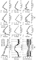
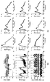
- Figure 8 shows another embodiment of the peak detection of the intracranial pressure waveform using the feature points of the arterial blood pressure waveform according to an embodiment of the present invention.
- FIG. 7 and 8 (a) show the clustering results for the three peaks of the arterial blood pressure waveform, intracranial pressure waveform, and intracranial pressure waveform.
- the vertical axis of the clustering graph for the three peaks of the intracranial breakdown waveform shows the time delay from the beginning of the waveform to each peak in ms. 7 and 8B, the peaks P1, P2, and P3 assigned as a result of the clustering of FIG. 7A are displayed on various waveforms measured at actual arbitrary times. You can check it.
- P2 peak is detected according to the time delay of the first observed peak or the position of the overlapping pulse patch of the corresponding arterial blood pressure waveform. .
- a flat was detected as P1, P2 or P3 in place of the peak.
- FIG 9 shows the results of verifying the accuracy of the peak detection of the intracranial pressure waveform using the feature points of the arterial blood pressure waveform according to an embodiment of the present invention.
- the detection accuracy of the peaks of the present invention was measured for each of the three peaks (P1, P2, P3).
- P1, P2, P3 the data of ten patients used as an example, each two hundred pulses were randomized. The skilled observer manually marked the P1, P2, and P3 peaks for a total of two thousand pulses.
- the result values of P1, P2, and P3 detection obtained through the peak detection method of the intracranial pressure waveform using the characteristic points of the arterial blood pressure waveform according to an embodiment of the present invention were not exposed to the observer.
- the absolute difference between the measurement time of each manually selected peak and the automatically detected peak measurement time was calculated as an error, and an error of 30 ms or less was ignored.
- the standard deviation of error (SDE) was calculated for each peak and found to be 4.16 at P1, 4.71 at P2, and 7.43 ms at P3. According to a 2008 paper by Hu, X., et al., The peak recognition function can be interpreted as having high accuracy when the SDE value is less than 10 ms.
- an embodiment of the present invention may also be implemented in the form of a recording medium including instructions executable by a computer, such as a program module executed by the computer.
- Computer readable media can be any available media that can be accessed by a computer and includes both volatile and nonvolatile media, removable and non-removable media.
- Computer readable media may include both computer storage media and communication media.
- Computer storage media includes both volatile and nonvolatile, removable and non-removable media implemented in any method or technology for storage of information such as computer readable instructions, data structures, program modules or other data.
- Communication media typically includes computer readable instructions, data structures, program modules, or other data in a modulated data signal such as a carrier wave, or other transmission mechanism, and includes any information delivery media.
- the peak detection apparatus of intracranial pressure waveform using the characteristic points of the arterial blood pressure waveform according to the embodiment of the present invention described above may be implemented as computer readable codes on a computer readable recording medium.
- Computer-readable recording media include all kinds of recording media having data stored thereon that can be decrypted by a computer system. For example, there may be a read only memory (ROM), a random access memory (RAM), a magnetic tape, a magnetic disk, a flash memory, an optical data storage device, and the like.
- the computer readable recording medium can also be distributed over computer systems connected over a computer network, stored and executed as readable code in a distributed fashion.
Landscapes
- Health & Medical Sciences (AREA)
- Life Sciences & Earth Sciences (AREA)
- Engineering & Computer Science (AREA)
- Animal Behavior & Ethology (AREA)
- Public Health (AREA)
- Veterinary Medicine (AREA)
- Biophysics (AREA)
- Pathology (AREA)
- Physics & Mathematics (AREA)
- Biomedical Technology (AREA)
- Heart & Thoracic Surgery (AREA)
- Medical Informatics (AREA)
- Molecular Biology (AREA)
- Surgery (AREA)
- General Health & Medical Sciences (AREA)
- Cardiology (AREA)
- Physiology (AREA)
- Nuclear Medicine, Radiotherapy & Molecular Imaging (AREA)
- Radiology & Medical Imaging (AREA)
- Neurosurgery (AREA)
- Hematology (AREA)
- Pulmonology (AREA)
- Vascular Medicine (AREA)
- Measuring Pulse, Heart Rate, Blood Pressure Or Blood Flow (AREA)
- Artificial Intelligence (AREA)
- Computer Vision & Pattern Recognition (AREA)
- Psychiatry (AREA)
- Signal Processing (AREA)
Abstract
본 발명은 동맥 혈압 파형의 특징점을 이용한 두개내압 파형의 피크 검출 장치 및 방법에 관한 것으로서, 본 발명의 일 측면에 따른 동맥 혈압 파형의 특징점을 이용한 두개내압 파형의 피크 검출 방법은 동맥 혈압 파형의 수축 피크에 기초하여 연속적인 두개내압 파형에서 파형의 시작점을 검출하는 단계; 파형의 시작점에 기초하여 연속적인 두개내압 파형에서 각각의 두개내압 파형을 구분하는 단계; 각각의 두개내압 파형에서 도함수 값을 도출하여 피크, 골, 및 플랫을 검출하는 단계; 각각의 두개내압 파형에서 검출된 파형의 시작점으로부터 검출된 피크의 시간 지연을 산출하여 시간 간격이 유사한 피크를 클러스터링하여 피크 클러스터를 생성하는 단계; 동맥 혈압 파형의 중복 맥박 패임의 시간 지연값에 기초하여 각각의 두개내압 파형에서 맥박 패임을 탐색하는 단계; 탐색된 두개내압의 맥박 패임에 기초하여 각각의 두개내압 파형에서 P1, P2 및 P3 피크를 검출하는 단계를 포함한다.
Description
본 발명은 동맥 혈압 파형의 특징점을 이용한 두개내압 파형의 피크 검출 장치 및 방법에 관한 것이다.
뇌 손상 환자들에게는 일반적인 중환자에게 적용되는 심장 및 호흡 모니터링에 더하여, 두개내압(intracranial pressure, ICP)의 모니터링이 이루어지고 있다. 이러한 두개내압 모니터링은 뇌의 상태를 정확히 알고, 뇌의 병태 생리학적 변화를 관찰하여 개별 환자에게 맞는 최적의 정상 상태를 만드는 것에 그 목적이 있다.
두개내압의 파형은 심장 박동, 호흡 주기 등과 같은 고조파(harmonics)를 가지며 뇌 혈관계에 대한 정보를 간접적으로 반영한다. 두개내압의 파형에서 보이는 주된 세 개의 피크는 차례로 P1, P2, P3로 명명되며 각각 다른 생리학적 기원을 가진다. 따라서, 세 개의 피크와 그 사이에 존재하는 골(trough)의 진폭(amplitude) 및 펄스의 시작점(pulse onset)으로부터 피크(peak)까지의 시간 지연(latency) 등의 특징은 두개강 내의 순응도(intracranial compliance) 또는 자동 조절 기능(cerebral autoregulation) 등에 대한 상태를 기술한다. 따라서, 이를 정확히 인식하여 해석하는 것은 매우 중요하다.
그러나 파형의 형태적 다양성으로 인해 세 개의 피크를 정확히 검출하는데 어려움이 있다. 따라서 다양한 연구를 통해 P1, P2, 및 P3 피크를 인식하는 기술의 정확도를 높이려는 노력이 있어왔다.
특히, 이와 관련한 종래의 기술 중, 미국공개특허 제2011-0201961호(Morphological clustering and analysis of intracranial pressure pulses, MOCAIP)는 모니터링된 두개내압 파형에서 세 개의 서브 피크를 인식하고, 서브 피크의 시간 지연(latency) 및 진폭(amplitude)을 이용하여 두개내압 파형의 형태학적인 변화를 살펴보는 방법을 제공한다.
그러나, 종래의 기술인 MOCAIP는 두개내압 파형의 피크들을 탐지하기 위해서, 여러 환자로부터 추출한 데이터를 수집해 놓은 참조 펄스 라이브러리(reference pulse library)를 활용한다. 참조 펄스 라이브러리에는 다양한 모양의 두개내압 파형의 정보들이 내재되어 있다. 해당 MOCAIP 기술은 이처럼 내재된 정보를 참조하여 피크 탐지의 정확도를 향상한다. 그러나 다양한 두개 내의 상태 또는 뇌 내 질환에 따라 두개내압 파형의 형태는 다양한 양상을 나타내며, 따라서 피크 탐지를 위해 참조할 수 있는 파형은 분석하고자 하는 데이터의 성질에 따라 달라진다. 때문에, 종래의 기술은 다양한 환자 사례로 이루어진 방대한 참조 펄스 라이브러리를 필요로 한다. 따라서 참조 펄스 라이브러리를 사용할 수 없는 오프라인 환경에서는 효율성이 저하된다. 또한, 종래의 기술은 신호의 결함이나 잡음을 줄이기 위한 방안으로 기록(recording)된 두개내압 파형의 개별 펄스를 평균화시킨 두개내압 펄스에서 피크를 탐지한다. 그러나 평균화시킨 두개내압 펄스는 실시간으로 다양하게 변화하는 개별 펄스의 특징을 담지 못한다. 따라서, 종래 기술의 경우 임상적 활용이 제한될 수 있다.
본 발명은 전술한 종래 기술의 문제점을 해결하기 위한 것으로서, 연속적인 두개내압 파형으로부터 자동적으로 P1, P2 및 P3 피크를 검출하는 방법을 제공하고자 한다.
또한, 참조 펄스 라이브러리 없이, 높은 정확도로 두개내압 파형에서 피크를 검출하는 방법을 제공하고자 한다.
다만, 본 실시예가 이루고자 하는 기술적 과제는 상기된 바와 같은 기술적 과제들로 한정되지 않으며, 또 다른 기술적 과제들이 존재할 수 있다.
상술한 기술적 과제를 달성하기 위한 기술적 수단으로서, 본 발명의 일 측면에 따른 동맥 혈압 파형의 특징점을 이용한 두개내압 파형의 피크 검출 방법은 동맥 혈압 파형의 수축 피크에 기초하여 연속적인 두개내압 파형에서 파형의 시작점을 검출하는 단계; 파형의 시작점에 기초하여 연속적인 두개내압 파형에서 각각의 두개내압 파형을 구분하는 단계; 각각의 두개내압 파형에서 도함수 값을 도출하여 피크, 골, 및 플랫을 검출하는 단계; 각각의 두개내압 파형에서 검출된 파형의 시작점으로부터 검출된 피크까지의 시간 지연을 산출하여 그 값이 유사한 피크를 클러스터링하여 피크 클러스터를 생성하는 단계; 동맥 혈압 파형의 중복 맥박 패임의 시간 지연값에 기초하여 각각의 두개내압 파형에서 맥박 패임을 탐색하는 단계; 탐색된 두개내압의 맥박 패임을 참조하여 각각의 두개내압 파형에서 P1, P2 및 P3 피크를 검출하는 단계를 포함한다.
또한, 본 발명의 다른 측면에 따른 동맥 혈압 파형의 특징점을 이용한 두개내압 파형의 피크 검출 장치는 두개내압 파형의 피크 검출 애플리케이션이 저장된 메모리부, 및 두개내압 파형의 피크 검출 애플리케이션과 인터페이싱하도록 정렬된 프로세싱 유닛을 포함한다. 이때, 프로세싱 유닛은 두개내압 파형의 피크 검출 애플리케이션의 실행에 따라, 동맥 혈압 파형 및 두개내압 파형을 센서부로부터 수신한다. 이어서, 수신된 동맥 혈압 파형 신호 및 두개내압 파형 신호를 디지털 데이터로 변환하여 메모리부에 저장한다. 다음으로, 동맥 혈압 파형의 수축 피크에 기초하여 연속적인 두개내압 파형에서 파형의 시작점을 검출한다. 또한, 파형의 시작점에 기초하여 연속적인 두개내압 파형에서 각각의 두개내압 파형을 구분하고 각각의 두개내압 파형에서 도함수 값을 도출하여 피크, 골, 및 플랫을 검출한다. 이어서, 각각의 두개내압 파형에서 검출된 파형의 시작점으로부터 검출된 피크의 시간 지연을 산출한다. 다음으로, 시간 간격이 유사한 피크를 클러스터링하여 피크 클러스터를 생성하고, 동맥 혈압 파형의 중복 맥박 패임의 시간 지연값에 기초하여 각각의 두개내압 파형에서 맥박 패임을 탐색한다. 이어서, 탐색된 두개내압의 맥박 패임을 참조하여 각각의 두개내압 파형에서 P1, P2 및 P3 피크를 검출한다.
전술한 본 발명의 과제 해결 수단 중 어느 하나에 의하면, 두개내압 파형에서 세 개의 피크를 자동으로 검출함에 따라, 지속적이고 직접적인 두개내압 파형의 모니터링이 가능하다.
또한, 두개내압 파형에서 세 개의 피크를 자동으로 검출하는데 있어서, 참조 펄스 라이브러리를 사용하지 않고 높은 정확도로 세 개의 피크를 검출 할 수 있는 효과가 있다.
도 1은 본 발명의 일 실시예에 따른 동맥 혈압 파형의 특징점을 이용한 두개내압 파형의 피크 검출 장치를 개략적으로 도시하고 있다.
도 2는 본 발명의 일 실시예에서 고려되는 두개내압 파형의 세 개의 피크를 도시하고 있다.
도 3은 본 발명의 일 실시예에 따른 동맥 혈압 파형의 특징점을 이용한 두개내압 파형의 피크 검출 방법을 상세히 설명하기 위한 순서도이다.
도 4는 본 발명의 일 실시예에 따른 연속적인 두개내압 파형에서 파형의 시작점을 검출하는 단계를 상세히 설명하기 위한 순서도이다.
도 5는 본 발명의 일 실시예에 따른 각각의 두개내압 파형에서 피크, 골, 및 플랫을 검출하는 단계를 상세히 설명하기 위한 순서도이다.
도 6은 본 발명의 일 실시예에 따른 각각의 두개내압 파형에서 검출된 피크들의 시간 지연을 산출하여 시간 지연 값이 유사한 피크끼리 그룹 지어 피크 클러스터로 클러스터링하는 단계를 상세히 설명하기 위한 순서도이다.
도 7은 본 발명의 일 실시예에 따른 동맥 혈압 파형의 특징점을 이용한 두개내압 파형의 피크 검출방법의 실시예를 나타내고 있다.
도 8은 본 발명의 일 실시예에 따른 동맥 혈압 파형의 특징점을 이용한 두개내압 파형의 피크 검출의 다른 실시예를 나타내고 있다
도 9는 본 발명의 일 실시예에 따른 동맥 혈압 파형의 특징점을 이용한 두개내압 파형의 피크 검출의 정확도 검증 결과를 나타내고 있다.
아래에서는 첨부한 도면을 참조하여 본 발명이 속하는 기술 분야에서 통상의 지식을 가진 자가 용이하게 실시할 수 있도록 본 발명의 실시예를 상세히 설명한다. 그러나 본 발명은 여러 가지 상이한 형태로 구현될 수 있으며 여기에서 설명하는 실시예에 한정되지 않는다. 그리고 본 발명을 명확하게 설명하기 위해서 도면에서 설명과 관계없는 부분은 생략하였으며, 명세서 전체를 통하여 유사한 부분에 대해서는 유사한 도면 부호를 붙였다.
명세서 전체에서, 어떤 부분이 다른 부분과 "연결"되어 있다고 할 때, 이는 "직접적으로 연결"되어 있는 경우뿐 아니라, 그 중간에 다른 소자를 사이에 두고 "전기적으로 연결"되어 있는 경우도 포함한다. 또한, 어떤 부분이 어떤 구성요소를 "포함"한다고 할 때, 이는 특별히 반대되는 기재가 없는 한 다른 구성요소를 제외하는 것이 아니라 다른 구성요소를 더 포함할 수 있는 것을 의미한다.
이하 도면을 참조하여, 본 발명의 일 실시예에 따른 동맥 혈압 파형의 특징점을 이용한 두개내압 파형의 피크 검출 장치 및 방법에 대하여 상세히 설명하도록 한다.
도 1은 본 발명의 일 실시예에 따른 동맥 혈압 파형의 특징점을 이용한 두개내압 파형의 피크 검출 장치를 개략적으로 도시하고 있다.
도 1을 참조하면, 본 발명의 일 실시예에 따른 동맥 혈압 파형의 특징점을 이용한 두개내압 파형의 피크 검출 장치는, 센서부(100), 메모리(200) 및 프로세싱 유닛(300), 디스플레이(400)를 포함한다. 이때 센서부(100) 및 디스플레이부(400)는 본 발명의 일 실시예에 따른 동맥 혈압 파형의 특징점을 이용한 두개내압 파형의 피크 검출 장치의 내부에 포함되거나 또는 동맥 혈압 파형의 특징점 검출 장치의 외부에 별도로 구비될 수 있다.
센서부(100)는 아날로그 증폭기(미도시됨) 및 디지털 컨버터(미도시됨) 등을 포함할 수 있으며, 동맥 혈압 또는 두개내압을 측정하여 디지털 신호로 변환할 수 있다.
메모리(200)에는 두개내압 파형의 피크 검출 애플리케이션이 저장될 수 있으며, 디지털 신호로 변환된 동맥 혈압 파형 데이터 및 두개내압 파형 데이터를 저장할 수 있다. 이때, 메모리(200)는 컴퓨터 판독 가능 명령어, 데이터 구조, 프로그램 모듈 또는 기타 데이터와 같은 정보의 저장을 위한 임의의 방법 또는 기술로 구현된 휘발성 및 비휘발성, 분리형 및 비분리형 매체를 모두 포함한다. 예를 들어, 메모리(200)는 ROM(Read Only Memory), RAM(Random Access Memory), 자기 테이프, 자기 디스크, 플래시 메모리, 광 데이터 저장장치, 콤팩트 플래시(compact flash; CF) 카드, SD(secure digital) 카드, 메모리 스틱(memory stick), 솔리드 스테이트 드라이브(solid-state drive; SSD) 및 마이크로(micro) SD 카드 등과 같은 낸드 플래시 메모리(NAND flash memory), 하드 디스크 드라이브(hard disk drive; HDD) 등과 같은 마그네틱 컴퓨터 기억장치 등을 포함할 수 있다.
프로세싱 유닛(300)은 두개내압 파형의 피크 검출 애플리케이션의 실행에 따라 메모리(200)에 저장된 동맥 혈압 파형 데이터 및 두개내압 파형 데이터에서 도함수 값을 도출하여 동맥 혈압 파형의 특징점을 검출하고, 두개내압 파형에서 세 개의 피크를 검출한다.
디스플레이(400)는 센서부(100)에 의하여 측정된 두개내압 파형 및 프로세싱 유닛(300)에 의하여 검출된 두개내압 파형 상의 세 개의 피크들을 실시간으로 표시할 수 있다. 또한 각각의 피크가 위치하는 지점을 색으로 구분하여 표시하는 것이 가능하다.
도 2는 본 발명의 일 실시예에서 고려되는 두개내압 파형의 세 개의 피크를 도시하고 있다.
도 2를 참조하면, 본 발명의 일 실시예에서 고려되는 두개내압 파형은 세 개의 P1, P2, 및 P3의 서브 펄스를 포함한다. 이때, 각 펄스의 마루를 파형에서 나타나는 순서대로 P1피크(peak), P2 피크 및 P3 피크라고 정의한다. 이러한 두개내압 파형의 세 개의 피크는 두개강 내의 순응도(intracranial compliance) 및 뇌 혈관 구조(cerebral vasculature)에 대한 정보를 내재하고 있다.
구체적으로, P1펄스는 심장의 수축기에 맥락얼기(choroid plexus)가 박동하면서 나타나는 첫 번째 압력파로써, 충격파(percussion wave) 라고 한다. 이어서, P1펄스 이후에 나타나는 P2펄스는 정맥의 반동 현상(rebound phenomenon)에 의해서 발생한다. 일반적으로, 정상적인 상황에서는 정맥의 반동 현상으로 발생하는 에너지가 흡수되면서 P2피크의 진폭이 P1피크의 진폭보다 작다. 그러나, 뇌의 순응도가 줄어들면 반동 현상이 심해지면서 P2피크의 진폭이 증가하게 되며, 때로는 P1피크보다 진폭이 더 커지는 경우도 발생한다. 따라서, 이와 같은 P2 피크의 진폭이 P1피크의 진폭보다 큰 역전 현상은 두개강 내부 순응도의 감소를 나타낸다. 또한, 심실 수축기가 끝나면 대동맥판이 닫히면서, 동맥 혈압 파형에 중복 맥박 패임(dicrotic notch)이 관찰되는 때와 동일한 시점에 두개내압 파형에서도 맥박 패임이 나타난다. 따라서, P3 펄스는 두개내압의 파형에 맥박 패임이 나타난 이후, 심실이 이완기에 들어서면서 발생한다.
상술한 바와 같이, 심장의 박동으로 인해 뇌 안으로 혈액이 유입되면 혈류의 진동에 의해 두개내압의 파형도 함께 변동하게 된다. 즉, 두개내압의 파형은 동맥 혈압의 파형과 연관이 되는데, 이는 심장의 박동에 의해 뇌의 혈액양(cerebral blood volume)이 변동되고, 이로 인해 뇌압이 변하기 때문이다.
또한, 뇌 손상 환자들에서 자동 조절 기능이 유지되는지 판단 할 수 있는 혈압과 뇌 관류압의 범위를 파악하는 것은 뇌 손상 환자의 치료 목표를 결정하는 데에 있어 대단히 중요하다. 그러나, 개별 환자에서 자동 조절 기능이 유지되는지를 파악하고, 혈압 조절의 범위를 결정하는데는 어려움이 따른다. 왜냐하면, 이론적으로 자동 조절 기능이 유지되는 혈압과 뇌 관류압의 범위를 결정하기 위해서는 동맥 혈압과 뇌 혈류에 대한 정보가 있어야 하나, 연속적인 뇌 혈류의 정보를 얻기가 쉽지 않기 때문이다. 그러나, 자동조절기능이 소실된 환자는 혈압이 상승하면 바로 뇌혈류가 상승하고, 이는 직접적인 뇌압의 상승으로 이어진다. 따라서, 뇌압에 대한 정보가 있으면, 혈압과 뇌압 간의 관계를 통해 자동 조절 기능이 유지되는지를 파악하는 것이 가능하다. 그러나, 현재 임상에서는 기술적인 한계로 인하여 두개내압 파형의 형태는 자세히 고려되지 않고 있으며, 두개내압 파형의 모니터링 결과의 해석은 측정된 두개내압의 평균을 살펴보는 정도로 제한되어 있다.
따라서, 본 발명의 일 실시예에 따른 동맥 혈압 파형의 특징점을 이용한 두개내압 파형의 피크 검출 장치는 두개내압 파형으로부터 세 개의 P1, P2, 및 P3파형을 자동으로 탐색하고, 각각의 파형의 피크에 대한 시간 지연 및 파형의 진폭 등에 대한 정보를 산출하는 방법을 제공한다. 또한, 동맥 혈압 파형의 특징점들과 두개내압 파형의 파형의 시작점으로부터 각각의 P1, P2 및 P3피크까지의 시간 지연 및 진폭 등의 다양한 변수들을 도출하고 변수들의 상관 관계를 분석하는 것이 가능하다. 따라서, 종래의 두개내압 파형을 분석하는 기술에서 필요로 했던 기존 환자들로부터 추출한 참조 펄스 라이브러리(reference pulse library) 없이도, 두개내압 파형의 피크를 검출하고 변화 양상을 모니터링 하는 것이 가능하다. 또한, 실시간으로 뇌 손상 환자의 두개강 내부 순응도의 악화 정도, 자기 조절 기능 손상 정도 등의 측정이 가능하며, 이는 뇌 손상 환자의 호전 여부를 예측하는데 유용하게 사용할 수 있다.
이하, 도 3을 참조하여 본 발명의 일 실시예에 따른 동맥 혈압 파형의 특징점을 이용한 두개내압 파형의 피크 검출 방법에 관하여 상세히 설명하기로 한다.
도 3은 본 발명의 일 실시예에 따른 동맥 혈압 파형의 특징점을 이용한 두개내압 파형의 피크 검출 방법을 상세히 설명하기 위한 순서도이다.
도 3을 참조하면, 본 발명의 일 실시예에 따른 동맥 혈압 파형의 특징점을 이용한 두개내압 파형의 피크 검출 방법은, 연속적인 두개내압 파형에서 파형의 시작점을 검출하는 단계(s100); 연속적인 두개내압 파형에서 각각의 두개내압 파형을 구분하는 단계(s200); 각각의 두개내압 파형에서 피크, 골, 및 플랫을 검출하는 단계(s300); 각각의 두개내압 파형에서 검출된 피크들의 시간 지연을 산출하여 시간 간격이 유사한 피크를 클러스터링하여 피크 클러스터를 생성하는 단계(s400); 각각의 두개내압 파형에서 맥박 패임을 탐색하는 단계(s500); 피크 클러스터를 오름차순 또는 내림차순으로 정렬하는 단계(s600) 및 두개내압 파형에서 P1, P2 및 P3 피크를 검출하는 단계(s700)를 포함한다.
먼저, 연속적인 두개내압 파형에서 파형의 시작점을 검출하는 단계(s100)에서, 프로세싱 유닛(300)은 동맥혈압 파형의 수축피크의 탐색 정보에 기초하여 연속적인 두개내압 파형에서 파형의 시작점을 검출한다.
도 4는 본 발명의 일 실시예에 따른 연속적인 두개내압 파형에서 파형의 시작점을 검출하는 단계를 상세히 설명하기 위한 순서도이다.
도 4를 참조하면, 본 발명의 일 실시예에 따른 연속적인 두개내압 파형에서 파형의 시작점을 검출하는 단계는, 동맥 혈압 파형에서 수축 피크를 검출하는 단계(s110); 동맥 혈압 파형에서 파형의 시작점을 검출하는 단계(s120); 및 두개내압 파형에서 파형의 시작점을 검출하는 단계(s130)를 포함한다.
본 발명의 일 실시예에 따르면 동맥 혈압 파형에서 수축 피크를 검출하는 단계(s110)에서, 프로세싱 유닛(300)은 동맥 혈압 파형에서 도함수 값을 도출하고, 분석의 초기에 임의의 시간 동안 동맥 혈압 파형의 최댓값과 평균값을 산출한다. 이어서, 산출된 평균값을 초과하고, 최댓값에 가까운 피크들을 타임 윈도(time window)에 수집한다. 이때, 수집되는 피크는 동맥 혈압 파형의 j번째 점을 Aj라 하고, 압력값을 PA,j라고 할 때, PA,j
-
1 < PA,j인 동시에 PA,j > PA,j
+
1 을 만족하는 점일 수 있다.
한편, 타임 윈도의 길이는 최댓값과 평균값을 분석하는 임의의 시간에 의존한다. 일례로, 3 초 내에 존재하는 파형에서 최댓값 및 평균값의 분석을 실행한 후 수축 피크의 후보를 수집했다면, 타임 윈도의 길이는 수집한 수축 피크의 후보가 늘어나면서 최소 3초에서 최대 30초의 범위를 가질 수 있다.
다음으로, 프로세싱 유닛(300)은 타임 윈도 내에 수집된 피크들의 평균 시간 간극(meanλj) 및 평균 압력값(meanPj)을 산출한다. 여기서 시간 간극(λA,j)이란, 타임 윈도 내에 수집된 j번째 피크에 대하여, 바로 직전의 피크와의 시간 간극을 나타낸다.
이어서, 프로세싱 유닛(300)은 타임 윈도 내에서 구한 평균 시간 간극(meanλj) 및 평균 압력값(meanPj)을 바탕으로 수축 피크(systolic peak)를 검출한다. 이때, 수축 피크는 타임 윈도 내에 추출된 수축 피크의 후보 중에서, | meanPA,j - PA,j | <
meanPA,j
* 0.15인 동시에 | mean λA,j - λA,j | < mean λA,j
* 0.15를 만족하는 j번째 피크들이 수축 피크(systolic peak)로 선택될 수 있다.
이어서, 동맥 혈압 파형에서 파형의 시작점을 검출하는 단계(s120)에서, 프로세싱 유닛(300)은 도함수의 최대 기울기 이전에 나타나는, 즉 수축 피크(20)의 직전에 존재하는 골 점들을 파형의 시작점으로 검출한다.
다음으로, 두개내압 파형에서 파형의 시작점을 검출하는 단계(s130)에서, 프로세싱 유닛(300)은 동맥 혈압 파형의 수축 피크의 탐색 정보에 기초하여 연속적인 두개내압 파형에서 파형의 시작점을 검출한다. 본 발명의 일 실시예에 따라, 동맥 혈압 파형의 수축 피크 측정 시간을 μA,j 라고 할 때, 프로세싱 유닛(300)은 μA,j 와 μA,j
+1 사이에 존재하는 두개내압 파형의 압력값 PI,j의 최솟값 minPI 와 최댓값 maxPI 및 평균값 meanPI를 산출한다. 이후, maxPI가 측정된 지점의 두개내압 파형의 측정 시간으로부터 μA,j
까지 시간 역순으로 검색할 때, 수학식 1을 만족하는 두개내압 파형의 골 Ik
을 두개내압 파형의 시작점으로 검출한다.
[수학식 1]
| PI,k - minPI | < | PI,k - meanPI |
다시 도 3을 참조하면, 본 발명의 일 실시예에 따른 동맥 혈압 파형의 특징점을 이용한 두개내압 파형의 피크 검출 과정에서, 프로세싱 유닛(300)은 두개내압 파형에서 파형의 시작점을 검출한 이후 검출된 파형의 시작점을 이용하여 연속적인 두개내압 파형에서 각각의 두개내압 파형을 구분한다(s200). 즉, 프로세싱 유닛(300)은 단계 (s100)에서 검출된 파형의 시작점과 다음 파형의 시작점까지로 나뉘는 파형을 각각 구분한다. 이때, 파형의 시작점 사이에 존재하는 두개내압 파형의 데이터는 하나의 벡터로 나타낼 수 있으며, 각각의 데이터는 동맥 혈압 파형과 두개내압 파형의 구분 없이 M
i, i=1,...,n으로 표시할 수 있다. 여기서, n은 동맥 혈압 파형 및 두개내압 파형에서 마지막 파형을 나타낸다.
한편, 본 발명의 일 실시예에 따른 동맥 혈압 파형의 특징점을 이용한 두개내압 파형의 피크 검출 방법은, M
i
내의 데이터의 개수를 64개로 선형 보간할 수 있다. 이때, i번째 파형인 M
i
내에 존재하는 데이터는 2차원 점으로 기술할 수 있으며, 아래의 수학식 2와 같이 표현할 수 있다.
[수학식 2]
x i,j = { ti,j, f(ti,j)}
여기서 ti,j 는 시간 도메인을 나타내고, f(ti,j)는 압력 도메인을 나타낸다.
또한, 본 발명의 일 실시예에 따른 동맥 혈압 파형의 특징점을 이용한 두개내압 파형의 피크 검출 방법은 연속적인 두개내압 파형에서 각각의 두개내압 파형을 구분하는 단계 이후에 부적절한 파형의 시작점을 가지는 파형을 필터링하는 단계를 더 포함할 수 있다. 부적절한 파형의 시작점을 가지는 파형을 필터링하는 단계는 구체적으로 ti,64
- ti,j 의 값으로 계산되는 심박 주기(cardiac cycle)를 이용할 수 있다. 따라서, 각각의 파형별로 이 전에 존재하는 세 개의 파형과 이 후에 존재하는 세 개의 파형의 심박 주기 평균(MCC)을 계산하고, ±MCC*0.15의 범위를 벗어나는 심박 주기를 가지는 파형들은 부적절하다고 판단하여 제외할 수 있다. 이후, 저역 필터를 통과시켜, 데이터의 노이즈를 제거하는 것이 가능하다. 일례로 저역 필터는 10Hz일 수 있으나, 이에 제한된 것은 아니다.
이어서, 본 발명의 일 실시예에 따른 동맥 혈압 파형의 특징점을 이용한 두개내압 파형의 피크 검출 방법은 각각의 두개내압 파형에서 피크, 골, 및 플랫을 검출한다(s300). 여기서 플랫은, 두개내압 파형에서 피크는 아니나 파형이 평평해지거나 압력 값이 감소하는 정도 또는 증가하는 정도가 미미한 지점을 나타낸다.
도 5는 본 발명의 일 실시예에 따른 각각의 두개내압 파형에서 피크, 골, 및 플랫을 검출하는 단계를 상세히 설명하기 위한 순서도이다.
도 5를 참조하면, 각각의 두개내압 파형에서 피크, 골, 및 플랫을 검출하는 단계는 두개내압 파형의 데이터를 정규화 하는 단계(s310); 정규화된 두개내압 파형에서 도함수 값을 도출하는 단계(s320); 및 도함수 값에 기초하여 피크, 골 및 플랫을 검출하는 단계(s330)를 포함한다.
본 발명의 일 실시예에 따르면, 두개내압 파형의 데이터를 정규화 하는 단계(s310)에서, M
i
내의 압력 도메인의 최댓값과 최솟값을 도출하며, 각각의 파형별 압력의 최솟값을 0으로, 최댓값을 100으로 치환한다. 이후, 각각의 xi,j는 정규화를 통하여 α
i,j = {τi,j, f(τi,j)}로 변환되며, τi,j및 f(τi,j)는 각각 수학식 3 및 수학식 4와 같다.
[수학식 3]

[수학식 4]

다음으로, 정규화된 두개내압 파형에서 도함수 값을 도출할 수 있다(s320). 두개내압 파형은 등간격으로 보간 되어 있으므로, 중앙차분법을 이용하여 도함수 값을 도출하는 것이 가능하다. 구체적으로, 파형에 존재하는 임의의 두 점 사이의 길이를 h = τi,j - τi,j
-1이라고 정의할 때, 도함수 값을 도출하는 방법은 수학식 5와 같다.
[수학식 5]

한편, 상술한 중앙차분법을 이용하는 방법은 하나의 데이터 값에 대한 도함수 값을 도출하기 위하여 이전에 존재하는 두 개의 데이터값과 이후에 존재하는 두 개의 데이터 값을 필요로 한다. 따라서, 이전과 이후에 두개 이상의 데이터가 존재하지 않는 경우는 수학식 6을 이용하여 도함수 값을 도출할 수 있다.
[수학식 6]

이어서, 도함수 값에 기초하여 피크, 골 및 플랫을 검출하는 단계(s330)에서 프로세싱 유닛(300)은 f'(τi,j
-1 ) > 0인 동시에 f'(τi,j
) < 0을 만족하는 경우, f(τi,j-1) < f(τi,j)이면, α
i,j를 피크로 검출하고, f(τi,j
-1) > f(τi,j)이면, α
i,j
-
1를 피크로 검출한다.
또한, f'(τi,j
-1) < 0인 동시에 f'(τi,j) > 0을 만족하는 경우, f(τi,j
-1) > f(τi,j)이면, α
i,j를 골로 검출하고, f(τi,j
-1) < f(τ
i,j)이면, α
i,j
-
1를 골로 검출한다.
한편, 프로세싱 유닛(300)은 α
i,j
-3부터 α
i,j
+3까지 일곱 개의 점이 모두 피크 또는 골이 아니고 |f'(τi,j)| < 1의 조건을 만족하는 경우, α
i,j를 플랫으로 검출한다. 이때, 본 발명의 일 실시예에 다르면 플랫은 여러 지점에 연속적으로 설정될 수 있다.
상술한 바와 같이, 본 발명의 일 실시예에 따른 두개내압 파형에서 피크, 골, 및 플랫을 검출하는 단계는 정규화 된 두개내압 파형의 모든 지점에 대하여 피크, 골 및 플랫과 같은 주요지점을 검출하며, α
i,j가 피크, 골 및 플랫 중 어느 하나인 주요 지점으로 검출될 경우, 검출된 주요 지점에 상응하는 정규화 이전의 데이터 지점인 xi,j도 마찬가지로 주요 지점으로 검출한다.
또한, 본 발명의 일 실시예에 따르면 두개내압 파형에서 피크, 골, 및 플랫을 검출하는 방법을 이용하여, 동맥 혈압 파형에서도 마찬가지로 피크, 골, 및 플랫 등의 주요지점을 검출하는 단계를 포함 할 수 있다. 따라서, 상술한 방법에 따라 동맥 혈압 파형 및 두개내압 파형의 데이터에서 모든 주요 지점이 검출될 수 있다.
다시 도 3을 참조하면, 본 발명의 일 실시예에 따른 동맥 혈압 파형의 특징점을 이용한 두개내압 파형의 피크 검출 방법은 각각의 두개내압 파형에서 피크, 골, 및 플랫을 검출하는 단계(s300) 이후에, 각각의 두개내압 파형에서 검출된 피크들의 시간 지연을 산출하여 그 값이 유사한 피크를 클러스터링하여 피크 클러스터를 생성한다(s400).
도 6은 본 발명의 일 실시예에 따른 각각의 두개내압 파형에서 검출된 피크들의 시간 지연을 산출하여 시간 지연 값이 유사한 피크를 클러스터링하여 피크 클러스터를 생성하는 단계(s400)를 상세히 설명하기 위한 순서도이다.
도 6을 참조하면, 두개내압 파형에서 검출된 피크들의 시간 지연을 산출하여 시간 지연 값이 유사한 피크를 클러스터링하여 피크 클러스터를 생성하는 단계(s400)는 시간 지연값을 이용하여 클러스터를 초기화 하는 단계(s410); 시간 지연 값이 유사한 피크를 클러스터링하여 피크 클러스터를 생성하는 단계(s420); 및 최소 거리 값을 가지는 클러스터로 피크를 재배정 하는 단계(s430)를 포함한다.
먼저, 시간 지연 값을 이용하여 클러스터를 초기화 하는 단계(s410)에서, 프로세싱 유닛(300)은 k번째 클러스터 Ck에 입력된 가장 최근의 원소 xi,j사이의 거리를 계산한다. 이때, k번째 클러스터 Ck에 입력된 가장 최근의 원소 xi,j사이의 거리 Dk(xi,j)는 아래 수학식 7에 의하여 계산될 수 있다.
[수학식 7]

여기서, L(xi,j)는 파형의 시작점으로부터 xi,j까지의 시간 간격을 나타내며 수학식 8에 의하여 계산될 수 있다.
[수학식 8]

또한, L(yk,p)는 k번째 클러스터Ck에 포함된 마지막 원소의 시간 간격을 나타낸다.
본 발명의 일 실시예에 따른 동맥 혈압 파형의 특징점을 이용한 두개내압 파형의 피크 검출 방법은 프로세싱 유닛(300)이 상술한 수학식 7을 이용하여 k번째 클러스터 Ck에 입력된 가장 최근의 원소들과 xi,j사이의 거리 Dk(xi,j)를 산출하고, 이를 기준으로 xi,j를 기존의 클러스터에 포함할 것인지, 혹은 새로운 클러스터를 생성할 것인지를 결정한다. 이때, 새로운 클러스터의 생성 분기점 q는 0.1초로 초기화 될 수 있다. 또한, Dk(xi,j)의 최솟값이 정해진 분기점 q보다 클 경우, 새로운 클러스터를 생성하여 해당하는 피크 xi,j를 배속하는 것을 반복 수행 함으로써 모든 피크가 클러스터에 배속될 수 있다. 이어서 생성된 클러스터의 개수가 5개 이상이면 분기점을 q에서 q+0.01로 증가시키고 상술한 과정을 반복 수행하며, 분기점 q가 0.2초 이상으로 증가하거나 클러스터의 개수가 5개 미만이면 클러스터를 초기화 하는 단계를 종료한다.
다음으로, 시간 지연 값이 유사한 피크를 클러스터링하여 피크 클러스터를 생성하는 단계(s420)에서 프로세싱 유닛(300)은 초기화된 각각의 클러스터의 시간 간격의 평균, mean(Ck)를 수학식 9를 이용하여 계산한다.
[수학식 9]

본 발명의 일 실시예에 따르면, 상술한 수학식 9에 의하여 계산된 클러스터의 시간 간격 평균을 이용하여 Ck 와 xi,j 사이의 거리를 새롭게 정의할 수 있으며, 새롭게 정의된 거리 D'k는 수학식 10과 같다.
[수학식 10]

이어서, 최소 거리 값을 가지는 클러스터로 피크를 재배정 하는 단계(s430)에서, 프로세싱 유닛(300)은 새롭게 정의된 D'k(xi,j)를 기준으로 클러스터를 결정하여 xi,j를 재배정할 수 있다. 이때 재배정할 클러스터를 결정하는 방법은 모든 클러스터와 xi,j사이의 거리를 계산함으로써 최소 거리를 갖는 클러스터가 결정할 수 있다. 따라서 일부의 피크는 기존의 클러스터에 그대로 배속될 수 있으나 기존의 클러스터가 최소 거리 값을 가지지 않는 경우, 해당 피크는 최소 거리 값을 가지는 클러스터로 재배정 할 수 있다. 따라서, 클러스터 분류의 정확도를 높일 수 있다.
이어서, 각각의 두개내압 파형에서 맥박 패임을 탐색하는 단계(s500)에서 프로세싱 유닛(300)은 동맥 혈압 파형의 중복 맥박 패임을 검출하고, 이를 이용하여 두개내압 파형에서 맥박 패임을 탐색한다.
프로세싱 유닛(300)은 동맥 혈압 파형에서 얻어진 주요 지점 가운데 골 또는 플랫 중 어느 하나를 중복 맥박 패임으로 검출할 수 있다. 구체적으로, μA,j + 0.1(μA,j+1 - μA,j)에서 μA,j + 0.25(μA,j
+1 - μA,j)까지의 범위를 탐색 윈도로 설정하고 수학식 11을 만족하는 동맥혈압 파형의 지점을 탐색하여 중복 맥막 패임의 후보로 추출할 수 있다. 이때, μA,j는PA,j의 압력 값을 가지는 동맥 혈압 파형의 수축피크 Aj의 측정 시간을 나타내며, 수학식 11은 아래와 같다.
[수학식 11]

이어서, 프로세싱 유닛(300)은 추출된 중복 맥박 패임의 후보 중, 압력 값이 가장 낮은 지점을 중복 맥박 패임으로 검출 하고, 동맥 혈압 파형의 파형의 시작점으로부터 중복 맥박 패임까지의 측정 시간 간극 Ln을 산출한다.
일반적으로 두개내압 파형의 P2 피크와 P3피크 사이에 존재하는 맥박 패임은 동맥 혈압 파형의 중복 맥박 패임과 유사한 시점에 나타난다. 따라서, 본 발명의 일 실시예에 따른 각각의 두개내압 파형에서 맥박 패임을 탐색하는 방법은, 산출된 Ln을 이용하여 두개내압 파형의 맥박 패임을 검출한다. 더욱 상세하게는, 프로세싱 유닛(300)은 파형의 시작점을 검출하는 단계(s100)에서 검출된 두개내압 파형의 파형의 시작점이 존재하는 시점에 Ln을 더하여 계산된 시점에서 가장 가까운 골을 두개내압 파형의 맥박 패임으로 검출한다. 이때, 두개내압 파형의 맥박 패임은 경우에 따라 존재하지 않을 수 있으므로, 각각의 파형의 심박 주기의 10% 길이에 해당하는 타임 윈도 내에서만 검색을 수행한다.
다음으로, 프로세싱 유닛(300)은 클러스터링된 피크 클러스터를 오름차순 또는 내림차순으로 정렬한다(s600).
이어서, 두개내압 파형에서 P1, P2 및 P3 피크를 검출하는 단계(s700)에서, 정렬된 각각의 피크 클러스터에서 피크를 추출하여 P1, P2 및 P3 피크로 검출할 수 있다. 구체적으로, 단계 (s500)에서 두개내압 파형의 맥박 패임이 발견된 경우, 프로세싱 유닛(300)은 피크 클러스터를 오름차순 또는 내림차순으로 정렬하여, 이를 기초로 P1피크를 검출한다. 일례로, 평균값이 작은 클러스터부터 오름차순으로 정렬하고, 정렬한 순서에 따라 첫 번째 클러스터에 배속된 피크를 P1으로 검출할 수 있다. 이어서, 검출된 두개내압 파형의 맥박 패임을 기준으로, 맥박 패임의 이전과 이후에 존재하는 피크를 탐색하고, 이전에 존재하는 피크를 P2 피크로 검출하고, 맥박 패임 이후에 존재하는 피크는 P3피크로 검출 할 수 있다.
반면, 단계 (s600)에서 두개내압 파형의 맥박 패임이 발견되지 않은 경우, 프로세싱 유닛(300)은 정렬된 피크 클러스터에서 P1, P2 및 P3 피크를 검출 할 수 있다. 일례로, 상술한 방법과 마찬가지로 평균값이 작은 클러스터부터 오름차순으로 정렬하였을 때, 정렬한 순서에 따라 첫 번째 클러스터에 배속된 피크를 P1으로 검출할 수 있다. 또한, 두번째 클러스터에 배속된 피크는 P2로, 세 번째 클러스터에 배속된 피크는 P3로 검출할 수 있다.
그러나, 예외적으로 첫 번째 클러스터에 배속된 피크들과 두개내압 파형의 시작점 사이의 평균 시간 간격이 200ms 이상인 경우에는 첫 번째 클러스터라고 할지라도 해당 피크를 P2로 검출한다. 이는 Kasprowicz M. 등이 수행한 연구(2012)에서 조사한 두개내압 파형의P2피크와 파형의 시작점 사이의 평균 시간 간격인 233.6±27.7ms를 참조하여 마련한 기준이다. 이 경우, 두 번째 클러스터에 배속된 피크는 자동적으로 P3로 검출한다.
또한, 하나의 파형 내에서 같은 클러스터에 배속된 피크가 두 개 이상일 경우, 즉, P1, P2, 및 P3 피크의 후보가 되는 피크가 두 개 이상일 경우에는 두개내압의 파형의 시작점으로부터 시간 간격이 가장 짧은 피크를 선택할 수 있다.
또한 하나의 파형 내에서 P1, P2, 및 P3중 어느 하나의 피크가 검출되지 않을 경우, 플랫 중의 하나로 해당 피크를 대체할 수 있다. 구체적으로 프로세싱 유닛(300)은 Mj 내에서 플랫으로 판별된 지점 xi,j중 D'k(xi,j) < 0.1을 만족하는 플랫을 탐색한다. 이후, k가 1일 경우 플랫의 xi,j를 P1으로 대체하고, k값이 2 일 경우는 P2로, k값이 3일 경우는 P3로 대체할 수 있다.
한편, 본 발명의 일 실시예에 따른 동맥 혈압 파형의 특징점을 이용한 두개내압 파형의 피크 검출 방법은 두개내압 파형에서 P1, P2 및 P3 피크를 검출하는 단계(s700) 이후에, P1, P2 및 P3 피크의 진폭, 두개내압 파형의 시작점으로부터 P1, P2 및 P3 피크까지의 지연 시간, 및 두개내압 파형에서 검출된 P1, P2 및 P3 피크의 개수 중 어느 하나를 산출하는 단계를 더 포함할 수 있다. 이어서, 산출된 계산 결과에 따라 두개내압 파형을 형태학적으로 분석하여 뇌 손상 환자의 예후를 판정하는 단계를 더 포함할 수 있다. 이때, 뇌 손상 환자의 예후는 뇌 손상 환자의 두개강 내부 순응도의 악화 여부 또는 자동 조절 기능의 이상 여부를 판단하는 것 일 수 있다.
구체적으로, 상술한 본 발명의 일 실시예에 따른 동맥 혈압 파형의 특징점을 이용한 두개내압 파형의 피크 검출 방법은 실제 외상성 뇌 손상 환자에게서 얻은 신호에 적용하여 환자 상태를 기술하는 데 필요한 변수들을 계산할 수 있다. 일 실시예로, P1, P2, 및P3의 진폭을 이용하여 각각의 두개내압의 파형에서 P1이 가장 큰 파형의 비율, P2가 가장 큰 파형의 비율, 및 P3가 가장 큰 파형의 비율을 계산하고 이를 각각 P1비율(P1-ratio), P2비율 (P2-ratio), 및 P3비율(P3-ratio)로 명명하였다. 이어서, 각각의 P1 비율, P2 비율, 및 P3 비율과 뇌 손상 환자의 예후의 상관 관계를 Mann-Whitney U test를 통하여 분석한 결과, 이 중 P1-ratio는 사망 환자에 비해 생존 환자에 비해 높았으며(p-value < 0.0001), P2-ratio는 반대로 사망 환자에게서 통계적으로 유의미하게 높았다(p-value < 0.004). 이는 두개강 내부 순응도가 악화될수록 P2가 증가하고 P1이 감소한다는 선행 연구의 결과를 입증할 수 있는 예가 될 수 있다. 따라서, 본 발명을 이용하여 환자의 두개강 내부 순응도의 악화 여부에 대한 모니터링이 가능함을 시사한다.
또 다른 실시예로 뇌 손상 환자들의 두개내압을 본 발명의 일 실시예에 따른 동맥 혈압 파형의 특징점을 이용한 두개내압 파형의 피크 검출 방법을 통해 두개내압 파형을 구분하고 각각의 두개내압 파형에서 피크를 감지하였다. 이어서, 각각의 두개내압 파형에서 감지한 피크들을 이용하여 하나의 두개내압 파형 내에 피크의 개수가 몇 개인지를 산출하였다. 또한, 산출된 결과와 뇌 손상 환자들의 두개강 내부 순응도의 상관 관계를 분석한 결과, 상술한 바와 같이 두개강 내부 순응도가 악화될 경우 P1피크의 개수는 감소하고 P2피크의 개수가 증가하였다. 그러나, 종래에는 하나의 두개내압 파형내에서 P2피크 만이 관찰되었다. 따라서, 본 발명의 일 실시예에 따라 도출된 바로는, 전체 파형 중 이와 같이 피크가 하나뿐인 파형의 비율에 대한 역치를 20%라 할 때 환자의 사망률 예측에 대한 positive predictive value는 77% 가량으로 나타났다. 달리 말하면, 피크가 하나뿐인 파형의 비율이 20%를 넘은 환자 중 77%는 실제로 사망했음을 의미한다. 이는, 직관적이고 이해하기 쉬운 변수를 이용하여 환자의 뇌 내 상태에 대한 진단이 가능함을 보여주는 예이다.
이러한 두개강 내부 순응도의 악화는 뇌종양, 뇌부종, 혈종 등과 같은 뇌 내의 부피 변화가 두개내압의 상승으로 이어지는 원인이 된다. 즉, 환자를 사망까지 이르게 할 수 있으므로 두개강 내부 순응도는 뇌 손상 환자의 상태를 진단하기 위해 관찰해야 하는 중요한 요인이다. 따라서 본 발명의 실시예를 통해 자동화된 방법으로 P1, P2, 및 P3 피크를 정확하게 인식한다면 환자의 경과 내지는 사망을 예측하는 데 기여할 수 있을 것이라 기대된다.
상술한 바와 같이 본 발명의 일 실시예에 따르면, 동맥 혈압 파형의 특징점을 이용하여 연속적인 두개내압 파형에서 자동으로 피크를 검출 함으로써, 지속적이고 직접적인 두개내압 파형의 모니터링이 가능하다.
또한, 두개내압 파형에서 세 개의 피크를 자동으로 검출하는데 있어서, 참조 펄스 라이브러리를 사용하지 않고 높은 정확도로 세 개의 피크를 검출 할 수 있는 효과가 있다.
도 7은 본 발명의 일 실시예에 따른 동맥 혈압 파형의 특징점을 이용한 두개내압 파형의 피크 검출의 실시예를 나타내고 있다.
도 8은 본 발명의 일 실시예에 따른 동맥 혈압 파형의 특징점을 이용한 두개내압 파형의 피크 검출의 다른 실시예를 나타내고 있다.
도 7및 도 8의 (a)에 동맥 혈압 파형, 두개내압 파형, 및 두개내압 파형의 세 개의 피크에 대한 클러스링 결과가 나타나 있다. 두개내압 파형의 세 개의 피크에 대한 클러스터링 그래프의 세로축은 파형의 시작점으로부터 각각의 피크까지의 시간 지연을 ms단위로 나타내고 있다. 또한, 도 7및 도 8의 (b)를 참조하면, 도 7의 (a)의 클러스터링의 결과로 배정된 P1, P2, 및 P3피크가 실제 임의의 시간별로 측정된 다양한 파형 상에 표기되는 것을 확인할 수 있다.
상술한 두개내압 파형의 피크 검출 방법에서 설명한 바와 같이, 일부 파형에서는 첫 번째로 관찰되는 피크의 시간 지연 또는 상응하는 동맥 혈압 파형의 중복 맥박 패임의 위치에 따라, P2피크로 검출된 것을 확인할 수 있다. 또한, 각 클러스터에 해당하는 피크가 존재하지 않을 경우, 플랫이 피크를 대신하여 P1, P2 또는 P3로 검출 되었다.
도 9는 본 발명의 일 실시예에 따른 동맥 혈압 파형의 특징점을 이용한 두개내압 파형의 피크 검출의 정확도 검증 결과를 나타내고 있다.
본 발명의 피크의검출 정확도가 세 개의 피크(P1, P2, P3) 각각에 대해 측정되었다. 예시로 사용한 환자 열 명의 데이터에 대하여, 각 이백 개의 펄스가 무작위로 추출되었다. 총 이천 개의 펄스에 대하여 숙련된 관측자가 수동으로 P1, P2, 및P3 피크를 표시하였다. 이 때 본 발명의 본 발명의 일 실시예에 따른 동맥 혈압 파형의 특징점을 이용한 두개내압 파형의 피크 검출 방법 통해 얻어진 P1, P2, 및 P3 검출의 결과 값은 관측자에게 노출되지 않았다. 이어서, 하나의 펄스에 대하여, 수동으로 선택된 각 피크의 측정 시간과 자동으로 감지된 피크의 측정 시간의 절댓값 차이를 오차로 계산하였으며, 30ms 이하의 오차는 무시되었다.
이와 같은 방법을 통해 P1, P2, 및 P3에 대하여 각각 98.2%, 97.1%, 94.5%의 정확도가 계산되었다. 또한, P1, P2, 및 P3피크의 시간 지연에 관한 평균 오차는 각각 -0.56, -0.02, 0.39 ms이었다. 상술한 오차의 유의성을 검정하고자 실시한 Z-test에서, P1의 유의확률(p-value)은 0.99, P2는 0.67, 및 P3는 0.32의 값을 나타냈다. 통계적으로 유의미한 유의확률 값이 통상적으로 0.05 이하라는 사실을 기반으로 해석할 때, 정확도 검증에서 나타난 오차가 유의미하지 않다는 것을 의미한다. 다시 말해 이는 본 발명의 일 실시예에 따른 동맥 혈압 파형의 특징점을 이용한 두개내압 파형의 피크 검출 방법에 의해 배정된 피크가 전문적인 관측자에 의해 배정된 피크와 유의하게 다르지 않았다는 것을 의미한다. 또한, 오차의 표준편차(Standard deviation of error, SDE)를 각 피크에 대해 계산한 결과, P1에서 4.16, P2에서 4.71, P3에서 7.43ms인 것으로 나타났다. Hu, X. 등의 2008년 논문에 따르면, peak 인식 기능에 있어 SDE 값이 10 ms 미만인 경우 높은 정확도를 보이는 것으로 해석할 수 있다.
한편, 본 발명의 일 실시예는 컴퓨터에 의해 실행되는 프로그램 모듈과 같은 컴퓨터에 의해 실행가능한 명령어를 포함하는 기록 매체의 형태로도 구현될 수 있다. 컴퓨터 판독 가능 매체는 컴퓨터에 의해 액세스될 수 있는 임의의 가용 매체일 수 있고, 휘발성 및 비휘발성 매체, 분리형 및 비분리형 매체를 모두 포함한다. 또한, 컴퓨터 판독가능 매체는 컴퓨터 저장 매체 및 통신 매체를 모두 포함할 수 있다. 컴퓨터 저장 매체는 컴퓨터 판독가능 명령어, 데이터 구조, 프로그램 모듈 또는 기타 데이터와 같은 정보의 저장을 위한 임의의 방법 또는 기술로 구현된 휘발성 및 비휘발성, 분리형 및 비분리형 매체를 모두 포함한다. 통신 매체는 전형적으로 컴퓨터 판독가능 명령어, 데이터 구조, 프로그램 모듈, 또는 반송파와 같은 변조된 데이터 신호의 기타 데이터, 또는 기타 전송 메커니즘을 포함하며, 임의의 정보 전달 매체를 포함한다.
상술한 본 발명의 일 실시예에 따른 동맥 혈압 파형의 특징점을 이용한 두개내압 파형의 피크 검출 장치는 컴퓨터로 읽을 수 있는 기록 매체에 컴퓨터가 읽을 수 있는 코드로서 구현되는 것이 가능하다. 컴퓨터가 읽을 수 있는 기록매체로는 컴퓨터 시스템에 의하여 해독될 수 있는 데이터가 저장된 모든 종류의 기록 매체를 포함한다. 예를 들어, ROM(Read Only Memory), RAM(Random Access Memory), 자기 테이프, 자기 디스크, 플래시 메모리, 광 데이터 저장장치 등이 있을 수 있다. 또한, 컴퓨터가 읽을 수 있는 기록매체는 컴퓨터 통신망으로 연결된 컴퓨터 시스템에 분산되어, 분산방식으로 읽을 수 있는 코드로서 저장되고 실행될 수 있다.
전술한 본 발명의 설명은 예시를 위한 것이며, 본 발명이 속하는 기술분야의 통상의 지식을 가진 자는 본 발명의 기술적 사상이나 필수적인 특징을 변경하지 않고서 다른 구체적인 형태로 쉽게 변형이 가능하다는 것을 이해할 수 있을 것이다. 그러므로 이상에서 기술한 실시예들은 모든 면에서 예시적인 것이며 한정적이 아닌 것으로 이해해야만 한다. 예를 들어, 단일형으로 설명되어 있는 각 구성 요소는 분산되어 실시될 수도 있으며, 마찬가지로 분산된 것으로 설명되어 있는 구성 요소들도 결합된 형태로 실시될 수 있다.
본 발명의 범위는 상기 상세한 설명보다는 후술하는 특허청구범위에 의하여 나타내어지며, 특허청구범위의 의미 및 범위 그리고 그 균등 개념으로부터 도출되는 모든 변경 또는 변형된 형태가 본 발명의 범위에 포함되는 것으로 해석되어야 한다.
Claims (22)
- 동맥 혈압 파형의 특징점을 이용한 두개내압 파형의 피크 검출 방법에 있어서,동맥 혈압 파형의 수축 피크에 기초하여 연속적인 두개내압 파형에서 파형의 시작점을 검출하는 단계;상기 파형의 시작점에 기초하여 연속적인 두개내압 파형에서 각각의 두개내압 파형을 구분하는 단계;상기 각각의 두개내압 파형에서 도함수 값을 도출하여 피크, 골, 및 플랫을 검출하는 단계;상기 각각의 두개내압 파형에서 상기 파형의 시작점으로부터 상기 검출된 피크의 시간 지연을 산출하여 시간 간격이 유사한 피크를 클러스터링하여 피크 클러스터를 생성하는 단계;동맥 혈압 파형의 중복 맥박 패임의 시간 지연값에 기초하여 상기 각각의 두개내압 파형에서 맥박 패임을 탐색하는 단계;상기 탐색된 두개내압의 맥박 패임에 기초하여 각각의 두개내압 파형에서 P1, P2 및 P3 피크를 검출하는 단계를 포함하는 두개내압 파형의 피크 검출 방법.
- 제 1 항에 있어서,연속적인 동맥 혈압 파형에서 수축 피크를 검출하는 단계;상기 수축 피크를 기초로 연속적인 동맥 혈압 파형에서 동맥 혈압 파형의 파형의 시작점을 검출하는 단계;상기 파형의 시작점을 기초로하여 상기 연속적인 동맥 혈압 파형을 각각의 동맥 혈압 파형으로 구분하는 단계;상기 각각의 동맥 혈압 파형에서 피크, 골, 및 플랫을 검출하는 단계; 및상기 검출된 골 중에서 중복 맥박 패임을 검출하는 단계를 더 포함하는 두개내압 파형의 피크 검출 방법.
- 제 1항에 있어서,연속적인 두개내압 파형에서 각각의 두개내압 파형을 구분하는 단계 이후에,부적절한 파형의 시작점을 가지는 두개내압 파형을 필터링 하는 단계를 더 포함하는 두개내압 파형의 피크 검출 방법.
- 제 1 항에 있어서,상기 두개내압 파형에서 P1, P2 및 P3 피크를 검출하는 단계 이후에,상기 P1, P2 및 P3 피크의 진폭을 분석하여 뇌 손상 환자의 예후를 판단하는 단계를 더 포함하는 두개내압 파형의 피크 검출 방법.
- 제 1 항에 있어서,상기 두개내압 파형에서 P1, P2 및 P3 피크를 검출하는 단계 이후에,상기 두개내압 파형의 시작점으로부터 상기 P1, P2 및 P3 피크까지의 지연 시간을 분석하여 뇌 손상 환자의 예후를 판단하는 단계를 더 포함하는 두개내압 파형의 피크 검출 방법.
- 제 1 항에 있어서,상기 두개내압 파형에서 P1, P2 및 P3 피크를 검출하는 단계 이후에,상기 두개내압 파형에서 검출된 상기 P1, P2 및 P3 피크의 개수를 분석하여 뇌 손상 환자의 예후를 판단하는 단계를 더 포함하는 두개내압 파형의 피크 검출 방법.
- 제 4 항 내지 제 6항 중 어느 한 항에 있어서,상기 뇌 손상 환자의 예후는뇌 손상 환자의 두개강 내부 순응도의 악화 여부 또는 자동 조절 기능의 이상 여부를 판단하는 것인 두개내압 파형의 피크 검출 방법.
- 제 1 항에 있어서,상기 두개내압 파형에서 파형의 시작점을 검출하는 단계는상기 동맥 혈압 파형의 j 번째 수축 피크의 측정 시간과 j+1 번째 수축 피크의 측정 시간 사이에 존재하는 두개내압 파형의 압력값의 최댓값, 최솟값, 및 평균값을 산출하는 단계; 및상기 최댓값이 측정된 지점의 두개내압 파형의 측정 시간으로부터 상기 j 번째 수축 피크 측정 시간까지 시간 역순으로 수학식 1을 만족하는 두개내압 파형의 골을 두개내압 파형의 시작점으로 검출하는 단계를 포함하는 것인 두개내압 파형의 피크 검출 방법.[수학식 1]| PI,k - minPI | < | PI,k - meanPI |여기서, PI,j 는 두개내압 파형의 압력값, minPI 는 두개내압 파형의 압력값의 최솟값, maxPI 는 두개내압 파형의 압력값의 최댓값, 및 meanPI 는 두개내압 파형의 압력값의 평균값을 나타냄.
- 제 1 항에 있어서,상기 각각의 두개내압 파형에서 도함수 값을 도출하여 피크, 골, 및 플랫을 검출하는 단계는두개내압 파형의 데이터를 정규화 하는 단계;상기 정규화된 두개내압 파형에서 도함수 값을 도출하는 단계; 및상기 도함수 값에 기초하여 피크, 골, 및 플랫을 검출하는 단계를 포함하는 것인 두개내압 파형의 피크 검출 방법.
- 제 1 항에 있어서,상기 각각의 두개내압 파형에서 맥박 패임을 탐색하는 단계는상기 동맥 혈압 파형의 파형의 시작점으로부터 중복 맥박 패임까지의 측정 시간 간극을 산출하여,상기 두개내압 파형의 파형의 시작점에 상기 중복 맥박 패임의 측정 시간 간극을 더한 시점에서 가장 가까운 골을 두개내압 파형의 맥박 패임으로 검출하는 것인 두개내압 파형의 피크 검출 방법.
- 제 1항에 있어서,상기 피크 클러스터를 오름차순 또는 내림차순으로 정렬하는 단계를 더 포함하는 두개내압 파형의 피크 검출 방법.
- 제 1 항에 있어서,상기 두개내압 파형에서 P1, P2 및 P3 피크를 검출하는 단계는상기 두개내압 파형에서 상기 맥박 패임이 발견된 경우,평균값이 작은 피크 클러스터에서 P1 피크를 검출하는 단계;상기 검출된 두개내압 파형의 맥박 패임 이전에 존재하는 피크를 P2 피크로 검출하는 단계; 및상기 검출된 두개내압 파형의 맥박 패임 이후에 존재하는 피크를 P3 피크로 검출하는 단계를 포함하는 두개내압 파형의 피크 검출 방법.
- 제 1 항에 있어서,상기 두개내압 파형에서 P1, P2 및 P3 피크를 검출하는 단계는상기 두개내압 파형에서 상기 맥박 패임이 발견되지 않은 경우,평균값이 작은 피크 클러스터부터 오름차순으로 정렬하는 단계;상기 정렬한 순서에 따라 첫 번째 클러스터에 배속된 피크를 P1 피크로 검출하는 단계두 번째 클러스터에 배속된 피크를 P2 피크로 검출하는 단계; 및세 번째 클러스터에 배속된 피크를 P3 피크로 검출하는 단계를 포함하는 두개내압 파형의 피크 검출 방법.
- 제 12 항 내지 제 13 항 중 어느 한 항에 있어서,상기 첫 번째 클러스터에 배속된 피크와 두개내압 파형의 파형의 시작점 사이의 평균 시간 간극이 200ms 이상인 경우,상기 첫 번째 클러스터에 배속된 피크를 P2로 검출하는 것인 두개내압 파형의 피크 검출 방법.
- 제 12항 내지 제 13 항 중 어느 한 항에 있어서,상기 두개내압 파형에서 P1, P2 및 P3 중 어느 하나의 피크가 검출되지 않을 경우,상기 플랫 중 어느 하나를 상기 검출되지 않는 피크로 검출하는 것인 두개내압 파형의 피크 검출 방법.
- 동맥 혈압 파형의 특징점을 이용한 두개내압 파형의 피크 검출 장치에 있어서,두개내압 파형의 피크 검출 애플리케이션이 저장된 메모리부, 및상기 두개내압 파형의 피크 검출 애플리케이션과 인터페이싱하도록 정렬된 프로세싱 유닛을 포함하되,상기 프로세싱 유닛은 상기 두개내압 파형의 피크 검출 애플리케이션의 실행에 따라,동맥 혈압 파형 및 두개내압 파형을 센서부로부터 수신하고 상기 수신된 동맥 혈압 파형 신호 및 두개내압 파형 신호를 디지털 데이터로 변환하여 메모리부에 저장하며,상기 동맥 혈압 파형의 수축 피크에 기초하여 연속적인 두개내압 파형에서 파형의 시작점을 검출하고,상기 파형의 시작점에 기초하여 연속적인 두개내압 파형에서 각각의 두개내압 파형을 구분하고상기 각각의 두개내압 파형에서 도함수 값을 도출하여 피크, 골, 및 플랫을 검출하여,상기 각각의 두개내압 파형에서 검출된 상기 파형의 시작점으로부터 상기 검출된 피크의 시간 지연을 산출하여 시간 간격이 유사한 피크를 클러스터링하여 피크 클러스터를 생성하고,동맥 혈압 파형의 중복 맥박 패임의 시간 지연값에 기초하여 상기 각각의 두개내압 파형에서 맥박 패임을 탐색한 후,상기 탐색된 두개내압의 맥박 패임에 기초하여 각각의 두개내압 파형에서 P1, P2 및 P3 피크를 검출하는 두개내압 파형의 피크 검출 장치.
- 제 16 항에 있어서,상기 동맥 혈압 파형 및 상기 두개내압 파형을 검출하는 센서부 및상기 검출된 동맥 혈압 파형, 상기 두개내압 파형, 및 상기 두개내압 파형에서 검출된 P1, P2 및 P3 피크를 실시간으로 표시하는 디스플레이를 더 포함하는 두개내압 파형의 피크 검출 장치.
- 제 17 항에 있어서,상기 디스플레이는상기 두개내압 파형에서 검출된 P1, P2 및 P3 피크를 색으로써 구분하여 표시하는 것인 두개내압 파형의 피크 검출 장치.
- 제 16항에 있어서,상기 프로세싱 유닛은연속적인 동맥 혈압 파형에서 수축 피크를 검출하고,상기 수축 피크를 기초로 연속적인 동맥 혈압 파형에서 동맥 혈압 파형의 파형의 시작점을 검출하여 상기 연속적인 동맥 혈압 파형을 각각의 동맥 혈압 파형으로 구분하며,상기 각각의 동맥 혈압 파형에서 피크, 골, 및 플랫을 검출하여,상기 검출된 골 중에서 중복 맥박 패임을 검출하는 것인 두개내압 파형의 피크 검출 장치.
- 제 16 항에 있어서,상기 프로세싱 유닛은상기 두개내압 파형에서 검출된 상기 P1, P2 및 P3 피크의 진폭,상기 두개내압 파형의 시작점으로부터 상기 두개내압 파형에서 검출된 상기 P1, P2 및 P3 피크까지의 지연 시간, 및상기 두개내압 파형에서 검출된 상기 P1, P2 및 P3 피크의 개수 중 어느 하나에 기초하여 뇌 손상 환자의 예후를 판단하도록 하는 것인 두개내압 파형의 피크 검출 장치.
- 제 20항에 있어서,상기 뇌 손상 환자의 예후는뇌 손상 환자의 두개강 내부 순응도의 악화 여부 또는 자동 조절 기능의 이상 여부를 판단하는 것인 두개내압 파형의 피크 검출 장치.
- 청구항1 내지 청구항 15중 어느 한 항에 따른 두개내압 파형의 피크 검출 방법을 실행시키기 위한 프로그램을 기록한 컴퓨터로 읽을 수 있는 매체.
Priority Applications (2)
| Application Number | Priority Date | Filing Date | Title |
|---|---|---|---|
| US15/567,858 US10799130B2 (en) | 2015-04-21 | 2016-04-20 | Device for extraction of peaks from continuous intracranial pressure waveform and detection method for the same |
| US16/938,243 US11690526B2 (en) | 2015-04-21 | 2020-07-24 | Device for extraction of peaks from continuous intracranial pressure waveform and detection method for the same |
Applications Claiming Priority (2)
| Application Number | Priority Date | Filing Date | Title |
|---|---|---|---|
| KR1020150055835A KR101746159B1 (ko) | 2015-04-21 | 2015-04-21 | 동맥 혈압 파형의 특징점을 이용한 두개내압 파형의 피크 검출 장치 및 방법 |
| KR10-2015-0055835 | 2015-04-21 |
Related Child Applications (2)
| Application Number | Title | Priority Date | Filing Date |
|---|---|---|---|
| US15/567,858 A-371-Of-International US10799130B2 (en) | 2015-04-21 | 2016-04-20 | Device for extraction of peaks from continuous intracranial pressure waveform and detection method for the same |
| US16/938,243 Continuation US11690526B2 (en) | 2015-04-21 | 2020-07-24 | Device for extraction of peaks from continuous intracranial pressure waveform and detection method for the same |
Publications (1)
| Publication Number | Publication Date |
|---|---|
| WO2016171476A1 true WO2016171476A1 (ko) | 2016-10-27 |
Family
ID=57144062
Family Applications (1)
| Application Number | Title | Priority Date | Filing Date |
|---|---|---|---|
| PCT/KR2016/004132 Ceased WO2016171476A1 (ko) | 2015-04-21 | 2016-04-20 | 동맥 혈압 파형의 특징점을 이용한 두개내압 파형의 피크 검출 장치 및 방법 |
Country Status (3)
| Country | Link |
|---|---|
| US (2) | US10799130B2 (ko) |
| KR (1) | KR101746159B1 (ko) |
| WO (1) | WO2016171476A1 (ko) |
Cited By (2)
| Publication number | Priority date | Publication date | Assignee | Title |
|---|---|---|---|---|
| US20190216422A1 (en) * | 2018-01-18 | 2019-07-18 | Neural Analytics, Inc. | Waveform visualization tool for facilitating medical diagnosis |
| US11129587B2 (en) | 2018-01-22 | 2021-09-28 | Novasignal Corp. | Systems and methods for detecting neurological conditions |
Families Citing this family (2)
| Publication number | Priority date | Publication date | Assignee | Title |
|---|---|---|---|---|
| EP4311481B1 (en) * | 2018-05-04 | 2026-01-14 | Lmd Ip, Llc | Improved personal health data collection |
| KR102230289B1 (ko) * | 2018-12-20 | 2021-03-19 | 고려대학교 산학협력단 | 광용적맥파(ppg) 신호 파형을 분석하는 방법, 이를 이용하여 사용자의 병리 상태를 추정하는 장치 및 그 방법 |
Citations (5)
| Publication number | Priority date | Publication date | Assignee | Title |
|---|---|---|---|---|
| KR20020002450A (ko) * | 2001-11-22 | 2002-01-09 | 명현성 | 맥상분석장치 |
| JP2004313468A (ja) * | 2003-04-16 | 2004-11-11 | Omron Healthcare Co Ltd | 脈波測定装置および生体波解析プログラム |
| KR20060111391A (ko) * | 2005-04-22 | 2006-10-27 | 후쿠다 덴쉬 컴퍼니 리미티드 | 바이오 정보 및 바이오 정보 리포트를 출력하기 위한 장치및 방법 |
| JP2011229767A (ja) * | 2010-04-28 | 2011-11-17 | Nintendo Co Ltd | 生体情報処理プログラム、生体情報処理装置、生体情報処理方法および生体情報処理システム |
| KR20120058243A (ko) * | 2010-11-29 | 2012-06-07 | 경희대학교 산학협력단 | 혈관경화도 진단을 위한 정보 제공 방법 |
Family Cites Families (3)
| Publication number | Priority date | Publication date | Assignee | Title |
|---|---|---|---|---|
| US20070276264A1 (en) * | 2002-10-30 | 2007-11-29 | Eide Per K | Method for analysis of single pulse pressure waves |
| JP3795866B2 (ja) * | 2003-01-24 | 2006-07-12 | コーリンメディカルテクノロジー株式会社 | カフ容積脈波測定装置、カフ容積脈波解析装置、圧脈波測定装置、および圧脈波解析装置 |
| US8647278B2 (en) * | 2010-10-26 | 2014-02-11 | Chongqing University | Method and system for non-invasive intracranial pressure monitoring |
-
2015
- 2015-04-21 KR KR1020150055835A patent/KR101746159B1/ko active Active
-
2016
- 2016-04-20 US US15/567,858 patent/US10799130B2/en active Active
- 2016-04-20 WO PCT/KR2016/004132 patent/WO2016171476A1/ko not_active Ceased
-
2020
- 2020-07-24 US US16/938,243 patent/US11690526B2/en active Active
Patent Citations (5)
| Publication number | Priority date | Publication date | Assignee | Title |
|---|---|---|---|---|
| KR20020002450A (ko) * | 2001-11-22 | 2002-01-09 | 명현성 | 맥상분석장치 |
| JP2004313468A (ja) * | 2003-04-16 | 2004-11-11 | Omron Healthcare Co Ltd | 脈波測定装置および生体波解析プログラム |
| KR20060111391A (ko) * | 2005-04-22 | 2006-10-27 | 후쿠다 덴쉬 컴퍼니 리미티드 | 바이오 정보 및 바이오 정보 리포트를 출력하기 위한 장치및 방법 |
| JP2011229767A (ja) * | 2010-04-28 | 2011-11-17 | Nintendo Co Ltd | 生体情報処理プログラム、生体情報処理装置、生体情報処理方法および生体情報処理システム |
| KR20120058243A (ko) * | 2010-11-29 | 2012-06-07 | 경희대학교 산학협력단 | 혈관경화도 진단을 위한 정보 제공 방법 |
Cited By (6)
| Publication number | Priority date | Publication date | Assignee | Title |
|---|---|---|---|---|
| US20190216422A1 (en) * | 2018-01-18 | 2019-07-18 | Neural Analytics, Inc. | Waveform visualization tool for facilitating medical diagnosis |
| US10849593B2 (en) * | 2018-01-18 | 2020-12-01 | Novasignal Corp. | Waveform visualization tool for facilitating medical diagnosis |
| US11963817B2 (en) | 2018-01-18 | 2024-04-23 | Neurasignal, Inc. | Waveform visualization tool for facilitating medical diagnosis |
| US12121392B2 (en) | 2018-01-18 | 2024-10-22 | Neurasignal, Inc. | Waveform visualization tool for facilitating medical diagnosis |
| US11129587B2 (en) | 2018-01-22 | 2021-09-28 | Novasignal Corp. | Systems and methods for detecting neurological conditions |
| US11684336B2 (en) | 2018-01-22 | 2023-06-27 | Novasignal Corp. | Systems and methods for detecting neurological conditions |
Also Published As
| Publication number | Publication date |
|---|---|
| US11690526B2 (en) | 2023-07-04 |
| US20180103862A1 (en) | 2018-04-19 |
| US20200352458A1 (en) | 2020-11-12 |
| US10799130B2 (en) | 2020-10-13 |
| KR101746159B1 (ko) | 2017-06-12 |
| KR20160125095A (ko) | 2016-10-31 |
Similar Documents
| Publication | Publication Date | Title |
|---|---|---|
| US11134880B2 (en) | Automatic method to delineate or categorize an electrocardiogram | |
| Chen et al. | An automatic R and T peak detection method based on the combination of hierarchical clustering and discrete wavelet transform | |
| Tan et al. | Icentia11k: An unsupervised representation learning dataset for arrhythmia subtype discovery | |
| Yeh et al. | Analyzing ECG for cardiac arrhythmia using cluster analysis | |
| WO2016163787A1 (ko) | 동맥 혈압 파형의 특징점 검출 장치 및 방법 | |
| US20220022799A1 (en) | Automatic method to delineate or categorize an electrocardiogram | |
| WO2016171476A1 (ko) | 동맥 혈압 파형의 특징점을 이용한 두개내압 파형의 피크 검출 장치 및 방법 | |
| US20100090798A1 (en) | Template synthesis for ecg/ppg based biometrics | |
| WO2022119155A1 (ko) | 설명 가능한 다중 심전도 부정맥 진단 장치 및 방법 | |
| CA2861500A1 (en) | Methods and systems for atrial fibrillation detection | |
| Smrdel et al. | Automated detection of transient ST-segment episodes in 24h electrocardiograms | |
| WO2019035639A1 (ko) | 딥러닝 기반의 패혈증 조기 감지방법 및 프로그램 | |
| Liu et al. | Automatic diagnosis of premature ventricular contraction based on Lyapunov exponents and LVQ neural network | |
| WO2020009387A1 (ko) | 순환신경망을 이용한 구간혈압 추정 방법 및 그 방법을 구현하기 위한 구간 혈압 추정 장치 | |
| WO2023101089A1 (ko) | 머신 러닝을 이용하여 심전도 파형 분류 방법 및 장치 | |
| WO2023018299A1 (ko) | 동맥압 웨이블릿 변환 기반 저혈압을 예측하기 위한 장치, 방법 및 이의 저혈압 예측 모델 학습 방법 | |
| WO2023038254A1 (ko) | 기계학습을 이용한 비침습적 당화혈색소 또는 혈당 추정 방법 및 장치 | |
| CN120873742A (zh) | 一种基于局部与全局特征融合的房颤预测方法及系统 | |
| CN120643188A (zh) | 一种基于脑电图信号的癫痫检测方法、系统、设备及介质 | |
| Wang et al. | Information extraction from multimodal ECG documents | |
| Syversen et al. | A Framework for Task-Specific Signal Quality Assessment: A Case Study in Heart Rate Estimation | |
| KR102852418B1 (ko) | 심전도 데이터의 주기성 분석을 이용한 순위패턴매칭 기반 부정맥 검출 방법 및 시스템 | |
| Abromavicius et al. | Algorithm for real-time detection of heart rate from noisy ECG signals supported by continuous blood pressure analysis | |
| Kim et al. | TS-ECG: A Deep Learning Approach for Classification Paroxysmal Atrial Fibrillation During Normal Sinus Rhythm | |
| Couceiro et al. | On the detection of premature ventricular contractions |
Legal Events
| Date | Code | Title | Description |
|---|---|---|---|
| 121 | Ep: the epo has been informed by wipo that ep was designated in this application |
Ref document number: 16783409 Country of ref document: EP Kind code of ref document: A1 |
|
| WWE | Wipo information: entry into national phase |
Ref document number: 15567858 Country of ref document: US |
|
| NENP | Non-entry into the national phase |
Ref country code: DE |
|
| 122 | Ep: pct application non-entry in european phase |
Ref document number: 16783409 Country of ref document: EP Kind code of ref document: A1 |