WO2016170804A1 - ユーザインタフェース装置及びユーザインタフェースシステム - Google Patents
ユーザインタフェース装置及びユーザインタフェースシステム Download PDFInfo
- Publication number
- WO2016170804A1 WO2016170804A1 PCT/JP2016/050811 JP2016050811W WO2016170804A1 WO 2016170804 A1 WO2016170804 A1 WO 2016170804A1 JP 2016050811 W JP2016050811 W JP 2016050811W WO 2016170804 A1 WO2016170804 A1 WO 2016170804A1
- Authority
- WO
- WIPO (PCT)
- Prior art keywords
- display
- image
- light
- user interface
- user
- Prior art date
- Legal status (The legal status is an assumption and is not a legal conclusion. Google has not performed a legal analysis and makes no representation as to the accuracy of the status listed.)
- Ceased
Links
Images






Classifications
-
- G—PHYSICS
- G06—COMPUTING OR CALCULATING; COUNTING
- G06F—ELECTRIC DIGITAL DATA PROCESSING
- G06F3/00—Input arrangements for transferring data to be processed into a form capable of being handled by the computer; Output arrangements for transferring data from processing unit to output unit, e.g. interface arrangements
- G06F3/01—Input arrangements or combined input and output arrangements for interaction between user and computer
- G06F3/03—Arrangements for converting the position or the displacement of a member into a coded form
- G06F3/041—Digitisers, e.g. for touch screens or touch pads, characterised by the transducing means
-
- G—PHYSICS
- G09—EDUCATION; CRYPTOGRAPHY; DISPLAY; ADVERTISING; SEALS
- G09G—ARRANGEMENTS OR CIRCUITS FOR CONTROL OF INDICATING DEVICES USING STATIC MEANS TO PRESENT VARIABLE INFORMATION
- G09G3/00—Control arrangements or circuits, of interest only in connection with visual indicators other than cathode-ray tubes
- G09G3/20—Control arrangements or circuits, of interest only in connection with visual indicators other than cathode-ray tubes for presentation of an assembly of a number of characters, e.g. a page, by composing the assembly by combination of individual elements arranged in a matrix no fixed position being assigned to or needed to be assigned to the individual characters or partial characters
-
- G—PHYSICS
- G06—COMPUTING OR CALCULATING; COUNTING
- G06F—ELECTRIC DIGITAL DATA PROCESSING
- G06F3/00—Input arrangements for transferring data to be processed into a form capable of being handled by the computer; Output arrangements for transferring data from processing unit to output unit, e.g. interface arrangements
- G06F3/01—Input arrangements or combined input and output arrangements for interaction between user and computer
- G06F3/03—Arrangements for converting the position or the displacement of a member into a coded form
- G06F3/041—Digitisers, e.g. for touch screens or touch pads, characterised by the transducing means
- G06F3/042—Digitisers, e.g. for touch screens or touch pads, characterised by the transducing means by opto-electronic means
-
- G—PHYSICS
- G06—COMPUTING OR CALCULATING; COUNTING
- G06F—ELECTRIC DIGITAL DATA PROCESSING
- G06F3/00—Input arrangements for transferring data to be processed into a form capable of being handled by the computer; Output arrangements for transferring data from processing unit to output unit, e.g. interface arrangements
- G06F3/01—Input arrangements or combined input and output arrangements for interaction between user and computer
- G06F3/048—Interaction techniques based on graphical user interfaces [GUI]
- G06F3/0481—Interaction techniques based on graphical user interfaces [GUI] based on specific properties of the displayed interaction object or a metaphor-based environment, e.g. interaction with desktop elements like windows or icons, or assisted by a cursor's changing behaviour or appearance
Definitions
- the present invention relates to a user interface device and a user interface system for detecting a user operation.
- Patent Document 1 captures a user's gesture performed while looking at a display, obtains a distance to the user's instruction point using a TOF sensor or the like, and displays a movement locus of the detected instruction point on a display screen.
- An input system is disclosed. In the conventional user interface device, distance detection is performed at a position away from the image in order to detect a gesture for remotely operating the image displayed on the display screen.
- Patent Document 2 discloses a three-dimensional image display device that displays a three-dimensional image corresponding to three-dimensional information generated by a light field camera or the like.
- an aerial image having a depth is displayed by projecting a light beam radiated from a display pixel such as a liquid crystal display through a display microlens.
- the present inventor has devised a new user interface device that combines the above-described techniques to detect a user's operation on a three-dimensional image and give the user a sense of touching and operating the three-dimensional image.
- a new user interface device that combines the above-described techniques to detect a user's operation on a three-dimensional image and give the user a sense of touching and operating the three-dimensional image.
- light emitted from the display surface to form a three-dimensional image becomes an obstacle to distance detection, and there is a problem that erroneous detection of a user's operation occurs. It was revealed.
- the user interface device is a user interface device that detects a user operation based on the movement of an object.
- the user interface device includes a display unit, a first distance detection unit, and a control unit.
- the display unit displays an image on the display surface.
- the first distance detection unit irradiates the first light and receives the reflected light of the first light, and detects the distance to the object that reflects the first light.
- the control unit detects a user operation based on the distance detected by the first distance detection unit.
- the control unit controls the display unit to alternately repeat a display period for displaying an image and a display stop period for stopping the display of the image.
- the first distance detection unit irradiates the first light during the display stop period to detect the distance to the object.
- a user interface system includes a user interface device and an electronic device connected to the user interface device.
- the user interface device inputs information indicating a detection result of a user operation to the electronic device.
- the distance detection unit since the distance detection unit detects the distance during the display stop period of the display unit, the display unit and the distance detection unit do not interfere with each other, and the user operation near the display surface is performed. False detection can be reduced.
- FIG. 9 Schematic diagram showing an overview of an input device according to Embodiment 1 of the present invention
- the figure for demonstrating the detection method of the user's operation by an input device 1 is a block diagram showing a configuration of an input device according to a first embodiment
- the figure for demonstrating the display method of the three-dimensional image by an input device Block diagram showing the configuration of an electronic device connected to an input device
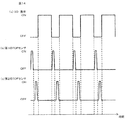
- Timing chart showing an example of operation timing of the input device according to the second embodiment 9 is a timing chart showing another example of the operation timing of the input device according to the second embodiment.
- Schematic diagram showing the outline of the input device according to the third embodiment FIG. 9 is a block diagram showing a configuration of an input device according to the third embodiment. Timing chart showing an example of operation timing of the
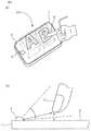
- FIG. 1 is a schematic diagram showing an outline of an input device according to Embodiment 1 of the present invention.
- FIG. 2A is a diagram for explaining a user operation on the input device.
- FIG. 2B is a diagram for explaining a method for detecting a user operation in a space on the display surface of the input device.
- the input device 1 includes a display unit 2 and a TOF (Time-of-Flight) sensor 3.
- the input device 1 is a device that detects a user operation on an image displayed on the display unit 2 and inputs information indicating a detection result to the electronic apparatus 4 or the like.
- the display unit 2 displays an image corresponding to the image G1 on the display surface at a position where the image G1 protrudes three-dimensionally from the display surface (a position closer to the user than the display surface).
- an image that is visually recognized by the user at a position protruding from the display surface is referred to as a “3D image (three-dimensional image)”.
- displaying the image corresponding to the 3D image G1 on the display surface so that the 3D image G1 is viewed stereoscopically is referred to as “displaying the 3D image G1”. Details of the display method of the 3D image G1 will be described later.
- the 3D image G1 is a stereoscopic image having a depth or a planar image displayed away from the display surface, and is an image showing operation members such as a switch, a button, a keyboard, a cursor, and an icon.
- the 3D image G1 may be a moving image or a still image.
- the TOF sensor 3 is a TOF type distance image sensor, detects the distance to the object to be measured, and outputs the detection result as a distance image.
- the input device 1 uses the TOF sensor 3 to sense the movement of the user's hand or finger 5 that is close to the spatial position where the user visually recognizes the 3D image G1, and detects the user's movement with respect to the 3D image G1. Detect operations. For example, as illustrated in FIG. 2A, when the user places the finger 5 on the display position of the 3D image G ⁇ b> 1, the input device 1 is a space in which the user visually recognizes the 3D image G ⁇ b> 1 based on the distance image of the TOF sensor 3. The position of the finger 5 approaching the target position is detected (see FIG. 2B), and the display unit 2 is controlled so that the 3D image G1 is pushed in accordance with the movement of the finger 5.
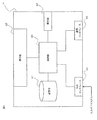
- FIG. 3 is a block diagram showing the configuration of the input device 1 according to this embodiment.
- the input device 1 includes a display unit 2 and a TOF sensor 3, and further includes a control unit 10 and an external interface 11.
- the control unit 10 includes a CPU, an MPU, and the like, and controls the operation of the entire input device 1.
- the control unit 10 has an internal memory (ROM, flash memory, etc.) for storing various data such as image data and programs.
- the control unit 10 implements various functions to be described later by executing a predetermined program stored in the internal memory.
- the control unit 10 may be realized only by a hardware circuit (ASIC, FPGA, etc.) such as an electronic circuit designed exclusively or a reconfigurable electronic circuit.
- the external interface 11 is composed of an interface circuit for performing information communication with an external device.
- the external interface 11 is wired to an external device and performs information communication according to a predetermined interface standard such as USB or HDMI.
- the external interface 11 may be an interface circuit that is wirelessly connected to an external device or the like.
- the external interface 11 may perform wireless communication with an external device according to a communication method such as Wi-Fi, Bluetooth (registered trademark), 3G, or LTE.
- the display unit 2 is composed of a liquid crystal display having a backlight, for example.
- the backlight is composed of, for example, a white LED (light emitting diode), and the light emitted from the backlight may include light in the near infrared region as well as visible light.
- the display unit 2 generates an image based on the image data on the display surface under the control of the control unit 10.
- the display part 2 may be comprised with the organic electroluminescent display which self-light-emits. A method of displaying the 3D image G1 by the display unit 2 will be described later.
- the TOF sensor 3 includes an LED 31 and a light receiving element 32.
- the LED 31 emits light having a wavelength band in the near infrared region (hereinafter referred to as “LED light”).
- the LED 31 is installed, for example, in the vicinity of a hemispherical lens provided in the vicinity of the display surface.
- the hemispherical lens condenses light from the outside of the input device 1 on the light receiving element 32.
- the light receiving element 32 has a plurality of pixels, and each pixel receives light having a wavelength band in the near infrared region.
- the TOF sensor 3 emits light obtained by pulse-modulating LED light and receives reflected light of the emitted LED light, and delay information on the light reception timing of the reflected light from the light emission timing of the LED light for each pixel of the light receiving element 32. get.
- the TOF sensor 3 generates and outputs a distance image indicating the distance to the object that reflects the reflected light based on the delay information for each pixel.
- the TOF sensor 3 is an example of a first distance detection unit in the user interface device.
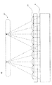
- the microlens array 21 is installed so as to cover the display surface of the display unit 2.
- the microlens array 21 is configured by arranging a plurality of microlenses in a matrix.
- the microlens array 21 may be composed of a group of microlenses having the same focal length, or may include microlenses having different focal lengths.
- the microlens array 21 is installed at a distance of about the focal length of each microlens (for example, the average focal length of each microlens) from the display surface of the display unit 2.
- each microlens of the microlens array 21 emits light incident from the display surface of the display unit 2 to the spatial region.
- an image corresponding to each microlens is projected on the display surface of the display unit 2 so that the light emitted from each microlens can reproduce the 3D image G1.
- display light emitted from the display surface is condensed in a spatial region facing the display unit 2 via the microlens array 21 to form a 3D image G1.
- image data indicating an image projected on the display surface of the display unit 2 is stored in the internal memory of the control unit 10.
- the control unit 10 reads out the image data from the internal memory and controls the display unit 2 to display an image indicated by the read image data on the display surface.
- the position where the 3D image is formed is a position in the vicinity of the display surface of the display unit 2, for example, within the range of the region where the distance from the display surface of the display unit 2 is 1 cm or more and 2 cm or less.
- Patent Document 2 discloses a 3D image display technique using a microlens.
- FIG. 5 is a block diagram illustrating a configuration of the electronic device 4.
- the electronic device 4 includes a control unit 40, a storage unit 41, a display unit 42, an operation unit 43, an external interface 44, and a communication interface 45.
- the electronic device 4 is, for example, a PC (personal computer), a tablet terminal, a smartphone, a mobile phone, or the like.
- the input device 1 is connected to the electronic device 4, and the input device 1 and the electronic device 4 constitute a user interface system.
- the control unit 40 is composed of, for example, a CPU and an MPU, and controls the operation of the entire electronic device 4.
- the control unit 40 implements various functions by executing a predetermined program.
- the control unit 40 may be realized only by a hardware circuit (ASIC, FPGA, etc.) such as a dedicated electronic circuit or a reconfigurable electronic circuit.
- the storage unit 41 is a storage medium that stores parameters, data, and programs necessary for realizing various functions of the control unit 40, and stores control programs executed by the control unit 40 and various data. ing.
- the storage unit 41 is configured by, for example, a hard disk (HDD) or a semiconductor storage device (SSD).
- the display unit 42 is composed of, for example, a liquid crystal display or an organic EL display.
- the operation unit 43 includes a keyboard, a mouse, a touch panel, and the like, and is a device for a user to give an instruction to the electronic device 4.
- the external interface 44 is an interface circuit for performing information communication through a wired connection with an external device such as the input device 1.
- the external interface 44 communicates data and commands with an external device in conformity with a predetermined interface standard such as USB or HDMI.
- the communication interface 45 is an interface circuit for performing information communication with external devices by wireless signals.
- the communication interface 45 performs wireless communication with an external device in accordance with a communication method such as Wi-Fi, Bluetooth (registered trademark), 3G, or LTE.
- the external interface 11 (see FIG. 3) of the input device 1 is wired to the external interface 44 of the electronic device 4.
- the external interface 11 may be wirelessly connected to the communication interface 45 instead of or in addition to this.
- the input device 1 displays the 3D image G1 in a space covering the display surface of the display unit 2 (see FIG. 1), and uses the TOF sensor 3 to push or touch the 3D image G1.
- a user operation is detected (see FIG. 2A).
- the TOF sensor 3 first displays the reflected light reflected from the object such as the finger 5 from the hemispherical lens as shown in FIG. The distance to the object existing in the space covering the display surface of the unit 2 is detected, and a distance image indicating the detection result is output.
- the control unit 10 of the input device 1 acquires a distance image from the TOF sensor 3 and displays, for example, the distance from the finger 5 to the display surface or the display of the 3D image G1 based on the distance from the TOF sensor 3 to the finger 5 in the distance image. Calculate the distance to the position. From this calculation result, the control unit 10 senses the movement of the finger 5 and detects a user operation based on the movement.
- the density of the light beam emitted from the display unit 2 to display the 3D image G1 is large (see FIG. 4), so the finger 5 is near the display surface.
- the light from the display surface is easily scattered by the finger 5.
- the light (display light) emitted from the display unit 2 may include near-infrared light as well as visible light. For this reason, when light emitted from the display unit 2 and scattered by the finger 5 enters the TOF sensor 3 in the space near the display surface, there is a problem that the TOF sensor 3 causes erroneous detection.
- the display unit 2 is controlled so as to intermittently display an image, and the LED light is irradiated from the TOF sensor 3 only during the display stop period, and a distance image of the space near the display surface is obtained. get.
- the distance image of the space near the display surface can be accurately detected by the TOF sensor 3 without erroneously detecting the light from the display unit 2.
- the space in the vicinity of the display surface is, for example, a space within 5 cm from the display surface of the display unit 2, and may be a space within 2 cm or a space within 1 cm.
- FIG. 6 is a flowchart showing the operation of the input device 1.
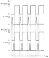
- FIG. 7 is a timing chart showing an example of the operation timing of the input device 1.
- the processing shown in this flowchart is repeatedly executed at a predetermined cycle by the control unit 10 of the input device 1 (see FIG. 7).
- the frame rate is assumed to be 30 fps as an example.
- Control unit 10 controls display unit 2 to display 3D image G1 (S1). At this time, the control unit 10 reads the image data corresponding to the 3D image G1 from the internal memory, controls the display unit 2, and forms the 3D image G1 from the display surface. Thereby, as shown in FIG. 1, 3D image G1 is displayed in the space which covers the display surface of the display part 2.
- FIG. 1 3D image G1 is displayed in the space which covers the display surface of the display part 2.
- the control unit 10 stops displaying the 3D image G1 after displaying the 3D image G1 for a predetermined period (S2).
- stopping the display of the image includes turning off the backlight (OFF), displaying an image in which the entire area of the display surface is black, and controlling both of them.
- the display period of the image on the display unit 2 is 29 frames, and the display stop period is 1 frame.
- the control unit 10 controls the TOF sensor 3 to emit LED light from the LED 31 of FIG. 3 for a predetermined period (for example, one frame) (S3).
- the TOF sensor 3 receives the reflected light of the LED light for each pixel in the light receiving element 32 in FIG. 3 and detects a distance image in the space above the display surface.
- control unit 10 acquires a distance image from the TOF sensor 3 and measures the distance to the object (S4). For example, the control unit 10 calculates the distance from the object to the display surface based on the distance from the TOF sensor 3 to the object (for example, the user's finger) in the distance image.
- control unit 10 updates the image data of the image displayed on the display surface based on the measurement result of step S4 (S5), and returns to step S1.
- step S4 when the distance measured in step S4 is equal to or less than a predetermined threshold such as the distance from the display surface to the display position of the 3D image G1, the image data is changed so that the display position of the 3D image G1 follows the position of the object. Update.
- the control unit 10 determines that an operation of “pressing the 3D image G ⁇ b> 1” has been performed, and outputs information indicating the user's operation to the electronic device 4.
- steps S1 to S5 are repeated.
- the control unit 10 continuously measures the distance of the object shown in the distance image.
- the control unit 10 senses the movement of an object such as a hand or a finger, and detects a user operation by a gesture or the like.
- the display unit 2 and the TOF sensor 3 do not interfere with each other. It is possible to reduce erroneous detection of a user operation on the 3D image G1.
- the cycle of the series of steps S1 to S5, the display period of the display unit 2, and the light emission period of the TOF sensor 3 do not have to be constant.
- the display period of the display unit 2 is set so as not to emit light during the light emission period of the TOF sensor 3.
- the light emission period of the TOF sensor 3 may be 2 frames with respect to 10 frames of the light emission period of the display unit 2.
- the light emission period of the TOF sensor 3 is set shorter than the display stop period of the display unit 2, for example, 1/40 second with respect to one frame of the display stop period of the display unit 2, and a margin is provided. Also good.
- the input device 1 is an example of a user interface device that detects a user operation based on the movement of an object such as the finger 5.
- the input device 1 includes a display unit 2, a TOF sensor 3, and a control unit 10.
- the display unit 2 displays an image on the display surface.
- the TOF sensor 3 irradiates the LED light and receives the reflected light of the LED light, and detects the distance to the object that reflects the LED light.
- the control unit 10 detects a user operation on the display image based on the distance detected by the TOF sensor 3.
- the control unit 10 controls the display unit 2 to alternately repeat a display period for displaying the 3D image G1 and a display stop period for stopping the display of the 3D image G1.
- the TOF sensor 3 irradiates LED light during the display stop period and detects the distance to the object.
- the display period of the display unit 3 and the light emission period of the TOF sensor 3 are intermittently controlled, and the light for detecting the distance from the TOF sensor 3 only when the image display of the display unit 3 is stopped. Irradiate. Thereby, the erroneous detection of the user's operation in the vicinity of the display surface is reduced.
- the display unit 2 displays an image on the display surface so that the user can visually recognize the 3D image G1 in the space on the user side from the display surface.
- the control unit 10 detects a user operation on the 3D image based on the distance detected by the TOF sensor 3. Thereby, even in a space in the vicinity of the display surface where the light density for displaying the 3D image G1 is large, the user's operation can be detected using the TOF sensor 3.
- control unit 10 determines that the user's operation is performed at the position of the 3D image G1 visually recognized by the user based on the distance detected by the TOF sensor 3, and displays the display unit according to the determination result.
- the image displayed by 2 may be controlled. Thereby, it is possible to give the user a feeling that he / she feels that he / she is operating by touching the 3D image G1.
- the 3D image G1 may be formed in the space on the user side from the display surface by display light emitted from the display surface. Thereby, a feeling of touching and operating the 3D image G1 formed by the display light can be obtained.
- the 3D image G1 may be an image showing an operation member. As a result, it is possible to give the user a feeling as if the user is operating the operation member that is raised on the display surface.
- FIG. 8 is a schematic diagram showing an outline of the user interface system according to the second embodiment.
- FIG. 9 is a block diagram illustrating configurations of the input device and the electronic apparatus according to the second embodiment.
- the user interface system according to the present embodiment includes first and second input devices 1 ⁇ / b> A and 1 ⁇ / b> B and an electronic apparatus 4. As shown in FIG. 8, the first and second input devices 1A and 1B are arranged adjacent to each other. As shown in FIG. 9, the configuration of the first and second input devices 1A and 1B is the same as the configuration of the input device 1 according to the first embodiment.
- the image display timing of the display unit 2 and the light emission timing of the TOF sensor 3 are controlled by the electronic device 4.
- Both the first and second input devices 1A and 1B are connected to the electronic device 4, and each independently accepts a user operation and inputs information to the electronic device 4.
- the LED light emitted from the LED 31 of one TOF sensor 3 of the first and second input devices 1A, 1B is converted into the other TOF sensor. 3 may be incident on the three light receiving elements 32. Therefore, the TOF sensors 3 of the input devices 1A and 1B may interfere with each other.
- the TOF sensor 3 of each input device 1A, 1B is caused to emit light during the display stop period, and the light emission timing is also shifted between the TOF sensors 3 of the two input devices 1A, 1B. Thereby, the interference between the TOF sensors 3 of the input devices 1A and 1B can be suppressed.
- the control unit 40 of the electronic device 4 to which the input devices 1A and 1B are connected performs the above timing control for the input devices 1A and 1B.
- FIG. 10 is a timing chart showing an example of operation timings of the input devices 1A and 1B of the user interface system according to the present embodiment.
- 10A shows the image display timing of the display unit 2 of the first input device 1A
- FIG. 10B shows the light emission timing of the TOF sensor 3 of the first input device 1A
- FIG. 10C shows the image display timing of the display unit 2 of the second input device 1B
- FIG. 10B shows the light emission timing of the TOF sensor 3 of the second input device 1B.
- the first and second input devices 1A and 1B intermittently display 3D images.
- the timing at which the display unit 2 of each input device 1A, 1B displays an image is controlled by the control unit 40 of the electronic device 4, for example.
- the control unit 40 of the electronic device 4 stops displaying images on the display unit 2 first, the TOF sensor 3 of the first input device 1A emits light, and the light emission of the TOF sensor 3 of the first input device 1A ends. After that, the TOF sensor 3 of the second input device 1B is caused to emit light. And the control part 40 complete
- the control unit 40 repeatedly executes the above processing.
- the TOF sensors 3 of the input devices 1A and 1B can detect a distance image without interfering with each other because their light emission periods do not overlap.
- the user interface system includes the input devices 1A and 1B and the electronic device 4 connected to the input devices 1A and 1B.
- the input devices 1A and 1B input information indicating the detection result of the user's operation to the electronic device 4.
- the TOF sensors 3 of the plurality of input devices 1A and 1B irradiate LED light at different timings. Thereby, each input device 1A, 1B can be used adjacently, without each TOF sensor 3 interfering.
- the electronic device 4 controls the light emission of the TOF sensors 3 of the input devices 1A and 1B.
- the light emission control of the TOF sensor 3 is not limited to this.
- a plurality of input devices 1A and 1B may be connected by wire or wirelessly, and one or both control units 10 may be controlled to irradiate LED light at different timings.
- the TOF sensors 3 of both the first and second input devices 1 ⁇ / b> A and 1 ⁇ / b> B are caused to emit light during the display stop period of the display unit 2 once.
- This control is not limited to this.
- the TOF sensor 3 of only one of the first and second input devices 1 ⁇ / b> A and 1 ⁇ / b> B may emit light during the display stop period of the display unit 2 once.
- each TOF sensor 3 of the first and second input devices 1A and 1B may be constant in all cycles in which display and display stop of 3D images are repeated, or may be changed for each cycle. Also good. For example, the timing at which the second input device 1B emits light after the first input device 1A emits light may be changed within a range that falls within the display stop period of the display unit 2. Further, the TOF sensors 3 of the input devices 1A and 1B may emit light alternately, or the order may be changed. Moreover, the light emission periods of the TOF sensors 3 of the input devices 1A and 1B may be the same or different. Also, the display period and the display stop period of the display unit 2 of the first and second input devices 1A and 1B may be changed for each cycle.
- timing control is performed so that the respective light emission periods do not overlap, thereby suppressing interference between the TOF sensors of adjacent input devices. be able to.
- one input device 1 includes one TOF sensor 3, but a plurality of TOF sensors may be provided in the input device.
- an input device including two TOF sensors will be described.
- FIG. 12 is a schematic diagram showing an outline of an input device including two TOF sensors according to the third embodiment.
- FIG. 13 is a block diagram illustrating a configuration of an input device according to the third embodiment.
- the input device 1C according to the present embodiment further includes a second TOF sensor 3 '.
- the second TOF sensor 3 ′ is disposed at a position facing the first TOF sensor 3 on the display surface of the display unit 2 of the input device 1 ⁇ / b> C.
- the second TOF sensor 3 ′ is an example of a second distance detection unit in the user interface device.
- the two TOF sensors 3 and 3 ′ of the input device 1 ⁇ / b> C may cause interference in the same manner as the TOF sensors 3 of the two input devices 1 ⁇ / b> A and 1 ⁇ / b> B in the second embodiment. Therefore, also in the present embodiment, the TOF sensors 3 and 3 ′ of the input device 1 ⁇ / b> C are caused to emit light at different timings during the display stop period. Moreover, in this embodiment, said timing control is performed by the control part 10 of 1 C of input devices.
- FIG. 14 is a timing chart showing an example of operation timing of the input device 1C according to the present embodiment.
- both the first and second TOF sensors 3, 3 ′ emit exclusively during the display stop period of the display unit 2 once. I am letting.
- only one of the first and second TOF sensors 3, 3 ′ is caused to emit light during one display stop period. Also good.
- the light emission timing and light emission period of each TOF sensor 3, 3 ′ may be constant over the entire period as in the case of each TOF sensor 3 of the first and second input devices 1 A, 1 B. It may be changed every time.
- the input device 1C further includes the second TOF sensor 3 '.
- the second TOF sensor 3 ′ emits the second light and receives the reflected light of the second light at a timing different from the timing at which the first light is emitted during the display stop period of the display unit 2. Then, the distance to the object reflecting the second light is detected.
- the two TOF sensors 3 and 3 ′ can be used without causing interference, and the detection accuracy of the user's operation can be improved.
- a 3D image is displayed using a microlens array so as to protrude from the display surface, but the microlens array may not be used.
- the 3D image is displayed (formed) so as to be raised from the display surface.
- the image display on the display unit 2 may be controlled by a spatial image method such as high-density directional display or integral imaging.
- the 3D image is displayed so as to protrude from the display surface using the microlens.
- the present invention is not limited to this. You may make it stand out and be observed.
- a binocular or multi-view image may be displayed on the display surface using polarized glasses, lenticular, parallax barrier, or the like. Even when the 3D image is projected from the display surface and observed by the above method, the image is intermittently displayed on the display surface and the distance is detected by the TOF sensor 3 during the image display stop period. Thus, it is possible to realize an operation that feels like touching a 3D image.
- a 2D image (an image that cannot be stereoscopically viewed) may be displayed on the display surface.
- the density of light for displaying the 2D image is large in the vicinity of the display surface. Therefore, even in such a case, erroneous detection of the TOF sensor 3 can be reduced by intermittently controlling the image display and irradiating the LED light of the TOF sensor 3 during the image display stop period.
- Such control of the TOF sensor 3 with respect to the 2D image is effective for an application that detects a user operation without touching the display surface. By realizing the user's operation without touching the display surface, it is possible to improve hygiene safety in, for example, a medical field or a service area.
- the input device is not limited thereto, and may be integrally mounted on the electronic apparatus.
- the input device may be mounted on a smartphone, a tablet terminal, or the like, or may be mounted as an operation interface on a home appliance or a game machine.
- the TOF sensor is shown as an example of the distance detection unit.
- the distance detection unit is not limited to the TOF sensor, and may be a pattern irradiation type distance image sensor, a stereo camera, an infrared camera, or the like. May be.
- Control unit 11 External interface 2 Display unit 3, 3 'TOF sensor 4
- Electronic device G1 3D image
Landscapes
- Engineering & Computer Science (AREA)
- Theoretical Computer Science (AREA)
- General Engineering & Computer Science (AREA)
- Physics & Mathematics (AREA)
- General Physics & Mathematics (AREA)
- Human Computer Interaction (AREA)
- Computer Hardware Design (AREA)
- Position Input By Displaying (AREA)
- User Interface Of Digital Computer (AREA)
Abstract
物体の動きに基づきユーザの操作を検出するユーザインタフェース装置(1)である。ユーザインタフェース装置は、表示部(2)と、第1の距離検出部(3)と、制御部(10)とを備える。表示部は、表示面に画像を表示する。第1の距離検出部は、第1の光を照射するとともに第1の光の反射光を受光して、第1の光を反射した物体までの距離を検出する。制御部は、第1の距離検出部によって検出された距離に基づいて、ユーザの操作を検出する。制御部は、画像を表示する表示期間と画像の表示を停止する表示停止期間とを交互に繰り返すように表示部を制御する。表示停止期間中に、第1の距離検出部は、第1の光を照射して、物体までの距離を検出する。
Description
本発明は、ユーザの操作を検出するユーザインタフェース装置及びユーザインタフェースシステムに関する。
ユーザの手や指などによるジェスチャーを検出して、ジェスチャーによるコンピュータ等の操作を可能にするユーザインタフェース装置が知られている。例えば、特許文献1は、ディスプレイを見ながら行われるユーザのジェスチャーを撮影し、TOFセンサなどによりユーザの指示ポイントまでの距離を求め、検出した指示ポイントの移動軌跡をディスプレイ画面に表示する3次元ジェスチャー入力システムを開示している。従来のユーザインタフェース装置では、ディスプレイ画面中に表示される画像を遠隔操作するためのジェスチャーを検出するために、画像から離れた位置において距離検出が行われている。
また、ホログラフィやインテグラル方式などの表示面から立体的に浮かび上がる画像、所謂三次元画像を形成する技術が知られている。特許文献2は、ライトフィールドカメラ等によって生成された三次元情報に対応する三次元画像が表示される三次元画像表示装置を開示している。特許文献1では、液晶表示器などの表示画素から輻射される光束を、表示用マイクロレンズを介して投影することにより、奥行きを有する空中像が表示される。
本発明者は、上記の技術を組み合わせて、三次元画像に対するユーザの操作を検出し、三次元画像に触って操作するような感覚をユーザに与えるという新たなユーザインタフェース装置を考案した。このような発明者の検討の下で、表示面の近傍においては、三次元画像を形成するために表示面から発光する光が距離検出の障害となり、ユーザの操作の誤検出が生じるという課題が明らかになった。
本発明は、画像を表示する表示面近傍におけるユーザの操作の誤検出を低減することができるユーザインタフェース装置及びシステムを提供することを目的とする。
本発明の一態様に係るユーザインタフェース装置は、物体の動きに基づきユーザの操作を検出するユーザインタフェース装置である。ユーザインタフェース装置は、表示部と、第1の距離検出部と、制御部とを備える。表示部は、表示面に画像を表示する。第1の距離検出部は、第1の光を照射するとともに第1の光の反射光を受光して、第1の光を反射した物体までの距離を検出する。制御部は、第1の距離検出部によって検出された距離に基づいて、ユーザの操作を検出する。制御部は、画像を表示する表示期間と画像の表示を停止する表示停止期間とを交互に繰り返すように表示部を制御する。第1の距離検出部は、表示停止期間中に第1の光を照射して、物体までの距離を検出する。
本発明の一態様に係るユーザインタフェースシステムは、ユーザインタフェース装置と、ユーザインタフェース装置に接続される電子機器とを備える。ユーザインタフェース装置は、ユーザの操作の検出結果を示す情報を前記電子機器に入力する。
本発明に係るユーザインタフェース装置及びシステムによると、表示部の表示停止期間中に距離検出部による距離検出が行われるため、表示部と距離検出部とが干渉せず、表示面近傍におけるユーザの操作の誤検出を低減することができる。
以下、添付の図面を参照して本発明に係るユーザインタフェース装置の一例として、実施の形態に係る入力デバイスについて説明する。
各実施形態は例示であり、異なる実施形態で示した構成の部分的な置換または組み合わせが可能であることは言うまでもない。実施の形態2以降では実施の形態1と共通の事項についての記述を省略し、異なる点についてのみ説明する。特に、同様の構成による同様の作用効果については、実施形態毎には逐次言及しない。
(実施の形態1)
0.概要
実施の形態1に係る入力デバイスの概要について、図1及び図2(a)、(b)を参照して説明する。図1は、本発明の実施の形態1に係る入力デバイスの概要を示す模式図である。図2(a)は、入力デバイスに対するユーザの操作を説明するための図である。図2(b)は、入力デバイスの表示面の上の空間におけるユーザの操作の検出方法を説明するための図である。
0.概要
実施の形態1に係る入力デバイスの概要について、図1及び図2(a)、(b)を参照して説明する。図1は、本発明の実施の形態1に係る入力デバイスの概要を示す模式図である。図2(a)は、入力デバイスに対するユーザの操作を説明するための図である。図2(b)は、入力デバイスの表示面の上の空間におけるユーザの操作の検出方法を説明するための図である。
図1に示すように、本実施形態に係る入力デバイス1は、表示部2と、TOF(Time-of-Flight)センサ3とを備える。入力デバイス1は、表示部2が表示する画像に対するユーザの操作を検出して、検出結果を示す情報を電子機器4等に入力するデバイスである。
表示部2は、表示面から画像G1が立体的に飛び出した位置(表示面よりもユーザ側の位置)に、ユーザによって視認されるように、表示面上に画像G1と対応する画像を表示する。以下、説明の便宜上、ユーザにより表示面から飛び出した位置に視認される画像を「3D画像(三次元画像)」という。又、3D画像G1が立体的に視認されるように、表示部2が表示面上に3D画像G1と対応する画像を表示することを、「3D画像G1を表示する」という。3D画像G1の表示方法の詳細については後述する。
3D画像G1は、奥行きを有する立体画像、又は表示面から離れて表示される平面画像であり、例えばスイッチ、ボタン、キーボード、カーソル、アイコンなどの操作部材を示す画像である。3D画像G1は、動画であってもよいし、静止画であってもよい。
TOFセンサ3は、TOF方式の距離画像センサであり、被測定物までの距離を検出し、検出結果を距離画像として出力する。
本実施形態に係る入力デバイス1は、TOFセンサ3を用いてユーザが3D画像G1を視認する空間的位置に近接するユーザの手や指5などの動きを感知して、3D画像G1に対するユーザの操作を検出する。例えば、図2(a)に示すようにユーザが3D画像G1の表示位置に指5を重ねた場合、入力デバイス1は、TOFセンサ3の距離画像に基づき、ユーザが3D画像G1を視認する空間的位置に近づく指5の位置を検出し(図2(b)参照)、3D画像G1が指5の動きに合わせて押し込まれるように表示部2を制御する。このように、TOFセンサ3を用いて、3D画像G1に対するユーザの操作を検出することにより、ユーザに、3D画像G1を触って操作していると感じる様な感覚を与えることができる。以下、本実施形態に係る入力デバイス1及び入力デバイス1が接続される電子機器4の構成について説明する。
1.構成
1-1.入力デバイスの構成
図3は、本実施形態に係る入力デバイス1の構成を示すブロック図である。入力デバイス1は、表示部2及びTOFセンサ3を備えるとともに、制御部10と、外部インタフェース11とをさらに備える。
1-1.入力デバイスの構成
図3は、本実施形態に係る入力デバイス1の構成を示すブロック図である。入力デバイス1は、表示部2及びTOFセンサ3を備えるとともに、制御部10と、外部インタフェース11とをさらに備える。
制御部10は、CPUやMPUなどで構成され、入力デバイス1全体の動作を制御する。制御部10は、画像データ等の各種のデータやプログラムを格納する内部メモリ(ROM,フラッシュメモリ等)を有する。制御部10は、内部メモリに格納された所定のプログラムを実行することによって、後述する各種の機能を実現する。制御部10は、専用に設計された電子回路や再構成可能な電子回路などのハードウェア回路(ASIC,FPGA等)のみで実現されてもよい。
外部インタフェース11は、外部機器と情報通信を行うためのインタフェース回路で構成される。外部インタフェース11は、外部機器に有線接続され、USBやHDMI等の所定のインタフェース規格に準拠して情報通信を行う。なお、外部インタフェース11は、外部機器等に無線接続するインタフェース回路であってもよい。例えば、外部インタフェース11は、Wi-FiやBluetooth(登録商標)、3G、LTE等の通信方式に従い外部機器と無線通信を行ってもよい。
表示部2は、例えばバックライトを有する液晶ディスプレイで構成される。バックライトは、例えば白色LED(発光ダイオード)で構成され、バックライトから発光される光には、可視光とともに近赤外領域の光も含まれ得る。表示部2は、制御部10の制御により、表示面上に画像データに基づく画像を生成する。なお、表示部2は、自発光する有機ELディスプレイで構成されてもよい。表示部2による3D画像G1の表示方法については後述する。
TOFセンサ3は、LED31と、受光素子32とを備える。LED31は、近赤外領域の波長帯を有する光(以下、「LED光」という)を発光する。LED31は、例えば表示面近傍に設けられた半球レンズの近傍に設置される。半球レンズは、入力デバイス1の外部からの光を受光素子32に集光する。受光素子32は、複数の画素を有し、各画素で近赤外領域の波長帯を有する光を受光する。TOFセンサ3は、LED光をパルス変調した光を照射するとともに照射したLED光の反射光を受光し、LED光の発光タイミングからの反射光の受光タイミングの遅延情報を受光素子32の画素毎に取得する。TOFセンサ3は、画素毎の遅延情報に基づき、反射光を反射した物体までの距離を示す距離画像を生成し、出力する。TOFセンサ3は、ユーザインタフェース装置における第1の距離検出部の一例である。
1-1-1.3D画像の表示方法
次に、図4を参照して、入力デバイス1の表示部2による3D画像G1の表示方法について説明する。本実施形態に係る入力デバイス1では、図4に示すように、マイクロレンズアレイ21が表示部2の表示面を覆うように設置されている。マイクロレンズアレイ21は、複数のマイクロレンズをマトリクス状に配列して構成される。マイクロレンズアレイ21は、同一の焦点距離を有するマイクロレンズ群で構成されてもよいし、異なる焦点距離を有するマイクロレンズを含んでもよい。マイクロレンズアレイ21は、表示部2の表示面から各マイクロレンズの焦点距離程度(例えば各マイクロレンズの焦点距離の平均値)の間隔をあけて設置される。
次に、図4を参照して、入力デバイス1の表示部2による3D画像G1の表示方法について説明する。本実施形態に係る入力デバイス1では、図4に示すように、マイクロレンズアレイ21が表示部2の表示面を覆うように設置されている。マイクロレンズアレイ21は、複数のマイクロレンズをマトリクス状に配列して構成される。マイクロレンズアレイ21は、同一の焦点距離を有するマイクロレンズ群で構成されてもよいし、異なる焦点距離を有するマイクロレンズを含んでもよい。マイクロレンズアレイ21は、表示部2の表示面から各マイクロレンズの焦点距離程度(例えば各マイクロレンズの焦点距離の平均値)の間隔をあけて設置される。
ここで、表示部2に対向する空間領域に3D画像G1を形成するために、マイクロレンズアレイ21の各マイクロレンズは、表示部2の表示面から入射した光を空間領域に出射する。この場合、各マイクロレンズから出射した光が3D画像G1を再現できるように、表示部2の表示面には、マイクロレンズ毎に対応した画像が投影されることとなる。本実施形態では、表示面から発する表示光がマイクロレンズアレイ21を介して表示部2に対向する空間領域において集光して、3D画像G1を形成する。
制御部10の内部メモリには、表示部2の表示面に投影される画像を示す画像データが格納されている。制御部10は、この画像データを内部メモリから読み出し、表示部2を制御して、表示面において読み出した画像データが示す画像を表示する。表示面からの光がマイクロレンズアレイ21を介して集光されることにより、ユーザは、あたかも3D画像G1が浮き出ているように視認することができる。3D画像が形成される位置は、表示部2の表示面の近傍の位置であり、例えば、表示部2の表示面からの距離が1cm以上2cm以下の領域の範囲内にある。なお、マイクロレンズを用いた3D画像表示の技術については、例えば特許文献2に開示がある。
1-2.電子機器の構成
次に、図5を参照して、入力デバイス1が接続される電子機器4の構成について説明する。図5は、電子機器4の構成を示すブロック図である。電子機器4は、制御部40と、記憶部41と、表示部42と、操作部43と、外部インタフェース44と、通信インタフェース45とを備える。電子機器4は、例えばPC(パーソナルコンピュータ)やタブレット端末、スマートフォン、携帯電話などである。電子機器4に対して入力デバイス1が接続され、入力デバイス1及び電子機器4は、ユーザインタフェースシステムを構成する。
次に、図5を参照して、入力デバイス1が接続される電子機器4の構成について説明する。図5は、電子機器4の構成を示すブロック図である。電子機器4は、制御部40と、記憶部41と、表示部42と、操作部43と、外部インタフェース44と、通信インタフェース45とを備える。電子機器4は、例えばPC(パーソナルコンピュータ)やタブレット端末、スマートフォン、携帯電話などである。電子機器4に対して入力デバイス1が接続され、入力デバイス1及び電子機器4は、ユーザインタフェースシステムを構成する。
制御部40は、例えばCPUやMPUで構成され、電子機器4全体の動作を制御する。制御部40は、所定のプログラムを実行することによって、各種の機能を実現する。制御部40は、専用に設計された電子回路や再構成可能な電子回路などのハードウェア回路(ASIC,FPGA等)のみで実現されてもよい。
記憶部41は、制御部40の各種の機能を実現するために必要なパラメータ、データ、及びプログラムを記憶する記憶媒体であり、制御部40で実行される制御プログラムや、各種のデータを格納している。記憶部41は、例えばハードディスク(HDD)や半導体記憶装置(SSD)で構成される。
表示部42は、例えば液晶ディスプレイや有機ELディスプレイで構成される。
操作部43は、キーボード、マウス、タッチパネルなどで構成され、電子機器4に対してユーザが指示を行うための装置である。
外部インタフェース44は、入力デバイス1等の外部機器と有線接続して情報通信を行うためのインタフェース回路である。外部インタフェース44は、USBやHDMI等の所定のインタフェース規格に準拠して、外部機器とデータやコマンドの通信を行う。
通信インタフェース45は、外部機器と無線信号により情報通信を行うためのインタフェース回路である。通信インタフェース45は、例えばWi-FiやBluetooth(登録商標)、3G、LTE等の通信方式に従い外部機器と無線通信を行う。
本実施形態では、入力デバイス1の外部インタフェース11(図3参照)は、電子機器4の外部インタフェース44に有線接続されている。入力デバイス1の外部インタフェース11が無線通信可能である場合、これに代えて、又は加えて、外部インタフェース11は通信インタフェース45に無線接続されてもよい。
2.動作
以下、本実施形態に係る入力デバイス1の動作について説明する。
以下、本実施形態に係る入力デバイス1の動作について説明する。
2-1.動作の概要
まず、図1~4を参照して、入力デバイス1におけるユーザの操作の検出動作の概要について説明する。本実施形態において、入力デバイス1は、表示部2の表示面を覆う空間中に3D画像G1を表示し(図1参照)、TOFセンサ3を用いて、3D画像G1を押したり触ったりするようなユーザの操作を検出する(図2(a)参照)。ユーザの操作の検出において、まず、TOFセンサ3は、図2(b)に示すように、LED光を照射して指5などの物体で反射した反射光を半球レンズから受光することにより、表示部2の表示面を覆う空間に存在する物体までの距離を検出し、検出結果を示す距離画像を出力する。入力デバイス1の制御部10は、TOFセンサ3から距離画像を取得し、例えば、距離画像におけるTOFセンサ3から指5までの距離に基づき、指5から表示面までの距離や3D画像G1の表示位置までの距離を算出する。この算出結果から、制御部10は、指5の動きを感知し、その動きに基づいてユーザの操作を検出する。
まず、図1~4を参照して、入力デバイス1におけるユーザの操作の検出動作の概要について説明する。本実施形態において、入力デバイス1は、表示部2の表示面を覆う空間中に3D画像G1を表示し(図1参照)、TOFセンサ3を用いて、3D画像G1を押したり触ったりするようなユーザの操作を検出する(図2(a)参照)。ユーザの操作の検出において、まず、TOFセンサ3は、図2(b)に示すように、LED光を照射して指5などの物体で反射した反射光を半球レンズから受光することにより、表示部2の表示面を覆う空間に存在する物体までの距離を検出し、検出結果を示す距離画像を出力する。入力デバイス1の制御部10は、TOFセンサ3から距離画像を取得し、例えば、距離画像におけるTOFセンサ3から指5までの距離に基づき、指5から表示面までの距離や3D画像G1の表示位置までの距離を算出する。この算出結果から、制御部10は、指5の動きを感知し、その動きに基づいてユーザの操作を検出する。
ここで、3D画像G1の表示位置を含む表示面近傍の空間では、3D画像G1を表示するために表示部2から発光した光束の密度が大きいので(図4参照)、指5が表示面近傍の空間に到達した場合、表示面からの光が指5に散乱されやすい。表示部2から発光した光(表示光)は、可視光とともに近赤外領域の光も含み得る。そのため、表示面近傍の空間において、表示部2から発光して指5に散乱された光がTOFセンサ3に入射すると、TOFセンサ3が誤検出を起こしてしまうという問題が想定される。
そこで、本実施形態では、画像の表示を間欠的に行うように表示部2を制御し、表示停止期間中にのみTOFセンサ3からLED光を照射して、表示面近傍の空間の距離画像を取得する。これにより、表示部2からの光を誤検出することなく、TOFセンサ3によって表示面近傍の空間の距離画像の検出を精度良く行うことができる。なお、表示面近傍の空間は、例えば表示部2の表示面からの距離が5cm以内の空間であり、2cm以内の空間であってもよいし、1cm以内の空間であってもよい。
2-2.入力デバイスの動作
次に、図1~3,6,7を参照して、入力デバイス1の動作について説明する。図6は、入力デバイス1の動作を示すフローチャートである。図7は、入力デバイス1の動作タイミングの一例を示すタイミングチャートである。
次に、図1~3,6,7を参照して、入力デバイス1の動作について説明する。図6は、入力デバイス1の動作を示すフローチャートである。図7は、入力デバイス1の動作タイミングの一例を示すタイミングチャートである。
本フローチャートが示す処理は、入力デバイス1の制御部10によって、所定の周期で繰り返し実行される(図7参照)。なお、以下の説明では、フレームレートは一例として30fpsとする。
制御部10は、表示部2を制御し、3D画像G1を表示させる(S1)。このとき、制御部10は、内部メモリから3D画像G1に対応する画像データを読み出し、表示部2を制御して、表示面から3D画像G1を形成する。これにより、図1に示すように、表示部2の表示面を覆う空間中に3D画像G1が表示される。
制御部10は、所定期間、3D画像G1を表示した後に、3D画像G1の表示を停止する(S2)。表示部2において、画像の表示の停止は、バックライトを消灯(OFF)したり、表示面の全領域が黒となる画像を表示したり、その双方の制御を行うことを含む。図7に示す例では、表示部2の画像の表示期間は29フレームであり、表示停止期間は1フレームである。
表示部2の表示の停止後、制御部10は、TOFセンサ3を制御して、図3のLED31からLED光を所定期間(例えば1フレーム)だけ発光させる(S3)。このとき、TOFセンサ3は、図3の受光素子32において画素毎にLED光の反射光を受光して、表示面の上の空間における距離画像を検出する。
次に、制御部10は、TOFセンサ3から距離画像を取得して、物体までの距離を測定する(S4)。例えば、制御部10は、距離画像におけるTOFセンサ3から物体(例えばユーザの指)までの距離に基づいて、物体から表示面までの距離を算出する。
次に、制御部10は、ステップS4の測定結果に基づいて、表示面に表示する画像の画像データを更新し(S5)、ステップS1に戻る。
例えば、ステップS4において測定された距離が表示面から3D画像G1の表示位置までの距離などの所定の閾値以下である場合、3D画像G1の表示位置を物体の位置に追従させるように画像データを更新する。また、このような場合、制御部10は、「3D画像G1を押す」という操作がなされたと判断し、ユーザの操作を示す情報を電子機器4に出力する。
以降、ステップS1~S5の処理を繰り返す。以上の処理を繰り返し実行することにより、制御部10は、距離画像に映る物体の距離を連続的に測定する。これにより、制御部10は、手や指などの物体の動きを感知して、ジェスチャーなどによるユーザの操作を検出する。
以上のように、表示部2の画像表示(S1,S2)とTOFセンサ3の距離検出(S3,S4)とを排他的に制御することにより、表示部2とTOFセンサ3とが干渉せず、3D画像G1に対するユーザの操作の誤検出を低減することができる。
以上の処理において、ステップS1~S5の一連の処理の周期や表示部2の表示期間、TOFセンサ3の発光期間は、それぞれ一定でなくてもよい。例えば、ステップS4において測定された物体の距離が閾値以下である場合や、物体の動きが所定値以上速い場合などに、TOFセンサ3の発光期間を長くしたり、TOFセンサ3の発光サイクルを短くしたりしてもよい。この場合、表示部2の表示期間は、TOFセンサ3の発光期間中には発光させないように設定する。例えば、表示部2の発光期間10フレームに対してTOFセンサ3の発光期間を2フレームなどとしてもよい。
また、TOFセンサ3の発光期間は、例えば表示部2の表示停止期間1フレームに対して1/40秒というように、表示部2の表示停止期間よりも短く設定して、マージンを持たせてもよい。
3.まとめ
以上のように、本実施形態に係る入力デバイス1は、指5などの物体の動きに基づきユーザの操作を検出するユーザインタフェース装置の一例である。入力デバイス1は、表示部2と、TOFセンサ3と、制御部10とを備える。表示部2は、表示面に画像を表示する。TOFセンサ3は、LED光を照射するとともにLED光の反射光を受光して、LED光を反射した物体までの距離を検出する。制御部10は、TOFセンサ3によって検出された距離に基づいて、表示画像に対するユーザの操作を検出する。制御部10は、3D画像G1を表示する表示期間と3D画像G1の表示を停止する表示停止期間とを交互に繰り返すように表示部2を制御する。TOFセンサ3は、表示停止期間中にLED光を照射して、物体までの距離を検出する。
以上のように、本実施形態に係る入力デバイス1は、指5などの物体の動きに基づきユーザの操作を検出するユーザインタフェース装置の一例である。入力デバイス1は、表示部2と、TOFセンサ3と、制御部10とを備える。表示部2は、表示面に画像を表示する。TOFセンサ3は、LED光を照射するとともにLED光の反射光を受光して、LED光を反射した物体までの距離を検出する。制御部10は、TOFセンサ3によって検出された距離に基づいて、表示画像に対するユーザの操作を検出する。制御部10は、3D画像G1を表示する表示期間と3D画像G1の表示を停止する表示停止期間とを交互に繰り返すように表示部2を制御する。TOFセンサ3は、表示停止期間中にLED光を照射して、物体までの距離を検出する。
以上の入力デバイス1によると、表示部3の表示期間とTOFセンサ3の発光期間とを間欠的に制御し、表示部3の画像表示の停止中にのみTOFセンサ3から距離検出のための光を照射する。これにより、表示面近傍におけるユーザの操作の誤検出が低減される。
また、表示部2は、表示面からユーザ側の空間中に、ユーザに3D画像G1が視認されるように表示面に画像を表示する。制御部10は、TOFセンサ3によって検出された距離に基づいて、3D画像に対するユーザの操作を検出する。これにより、3D画像G1を表示するための光の密度が大きい表示面の近傍の空間中であっても、TOFセンサ3を用いてユーザの操作を検出することができる。
また、制御部10は、TOFセンサ3によって検出された距離に基づいて、ユーザの操作が、ユーザに視認される3D画像G1の位置において行われたことを判断し、判断結果に応じて表示部2によって表示される画像を制御してもよい。これにより、ユーザに、3D画像G1を触って操作していると感じる様な感覚を与えることができる。
3D画像G1は、表示面から発する表示光によって、表示面からユーザ側の空間中に形成されてもよい。これにより、表示光によって形成された3D画像G1を触って操作する感覚が得られる。3D画像G1は、操作部材を示す画像であってもよい。これにより、ユーザに、表示面に浮き出た操作部材を操作している様な感覚を与えることができる。
(実施の形態2)
実施の形態1では、1つの入力デバイス1を用いる場合について説明したが、複数の入力デバイス1を同時に使用してもよい。実施の形態2では、2つの入力デバイスを使用する場合のユーザインタフェースシステムについて説明する。
実施の形態1では、1つの入力デバイス1を用いる場合について説明したが、複数の入力デバイス1を同時に使用してもよい。実施の形態2では、2つの入力デバイスを使用する場合のユーザインタフェースシステムについて説明する。
図8は、実施の形態2に係るユーザインタフェースシステムの概要を示す模式図である。図9は、実施の形態2に係る入力デバイス及び電子機器の構成を示すブロック図である。本実施形態に係るユーザインタフェースシステムは、第1及び第2の入力デバイス1A,1Bと、電子機器4とを含む。第1及び第2の入力デバイス1A,1Bは、図8に示すように、互いに隣接して配置されている。図9に示すように、第1及び第2の入力デバイス1A,1Bの構成は、それぞれ実施の形態1に係る入力デバイス1の構成と同様である。第1及び第2の入力デバイス1A,1Bは、電子機器4により、表示部2の画像表示タイミングと、TOFセンサ3の発光タイミングとが制御される。
第1及び第2の入力デバイス1A,1Bは、共に電子機器4に接続されており、それぞれ独立してユーザの操作を受け付けて、電子機器4に情報を入力する。ここで、各入力デバイス1A,1Bがユーザの操作を検出する際、第1及び第2の入力デバイス1A,1Bのうちの一方のTOFセンサ3のLED31から発したLED光が、他方のTOFセンサ3の受光素子32に入射することがある。そのため、各入力デバイス1A,1BのTOFセンサ3同士が干渉してしまうことがある。
そこで、本実施形態では、表示停止期間中に各入力デバイス1A,1BのTOFセンサ3を発光させるとともに、2つの入力デバイス1A,1BのTOFセンサ3間においても、発光タイミングをずらす。これにより、各入力デバイス1A,1BのTOFセンサ3間の干渉を抑制することができる。また、本実施形態では、各入力デバイス1A,1Bが接続されている電子機器4の制御部40により、各入力デバイス1A,1Bに対する上記のタイミング制御を行う。
図10は、本実施形態に係るユーザインタフェースシステムの各入力デバイス1A,1Bの動作タイミングの一例を示すタイミングチャートである。図10(a)は、第1の入力デバイス1Aの表示部2の画像表示タイミングを示し、図10(b)は、第1の入力デバイス1AのTOFセンサ3の発光タイミングを示す。図10(c)は、第2の入力デバイス1Bの表示部2の画像表示タイミングを示し、図10(b)は、第2の入力デバイス1BのTOFセンサ3の発光タイミングを示す。
図10(a),(c)に示すように、第1及び第2の入力デバイス1A,1Bは、それぞれ間欠的に、3D画像を表示している。各入力デバイス1A,1Bの表示部2が画像を表示するタイミングは、例えば電子機器4の制御部40によって制御されている。電子機器4の制御部40は、表示部2での画像表示を停止すると、まず、第1の入力デバイス1AのTOFセンサ3を発光させ、第1の入力デバイス1AのTOFセンサ3の発光が終了した後に、第2の入力デバイス1BのTOFセンサ3を発光させる。そして、制御部40は、表示部2の表示停止期間中に、第2の入力デバイス1BのTOFセンサ3の発光を終了する。制御部40は、以上の処理を繰り返し実行する。これにより、各入力デバイス1A,1BのTOFセンサ3は、それぞれの発光期間が重ならないので、互いに干渉することなく距離画像を検出することができる。
以上のように、本実施形態に係るユーザインタフェースシステムは、入力デバイス1A,1Bと、入力デバイス1A,1Bに接続される電子機器4とを備える。入力デバイス1A,1Bは、ユーザの操作の検出結果を示す情報を電子機器4に入力する。複数の入力デバイス1A,1BのそれぞれのTOFセンサ3は、それぞれ異なるタイミングでLED光を照射する。これにより、それぞれのTOFセンサ3が干渉することなく、各入力デバイス1A,1Bを隣接して使用できる。
また、本実施形態では、電子機器4が、入力デバイス1A,1BのそれぞれのTOFセンサ3の発光を制御した。しかし、TOFセンサ3の発光の制御はこれに限定されない。例えば、複数の入力デバイス1A,1B同士を有線又は無線接続して、一方又は両方の制御部10が、それぞれ異なるタイミングでLED光を照射するように制御してもよい。
また、図10に示す一例では、一回の表示部2の表示停止期間中に第1及び第2の入力デバイス1A,1Bの両方のTOFセンサ3を発光させたが、TOFセンサ3の発光タイミングの制御はこれに限らない。図11に示すように、一回の表示部2の表示停止期間中に第1及び第2の入力デバイス1A,1Bの片方のみのTOFセンサ3を発光させてもよい。
また、第1及び第2の入力デバイス1A,1Bの各TOFセンサ3の発光タイミングは、3D画像の表示と表示停止を繰り返す周期の全てにおいて一定であってもよいし、周期毎に変化させてもよい。例えば、第1の入力デバイス1Aの発光後に第2の入力デバイス1Bを発光させるタイミングを、表示部2の表示停止期間中に収まる範囲内で変化させてもよい。また、各入力デバイス1A,1BのTOFセンサ3は交互に発光してもよいし、順番が入れ替わってもよい。また、各入力デバイス1A,1BのTOFセンサ3の発光期間は、同一であってもよいし、異なってもよい。また、第1及び第2の入力デバイス1A,1Bの表示部2の表示期間及び表示停止期間についても、周期毎に変化させてもよい。
また、3つ以上の入力デバイスを用いる場合についても、上記の説明と同様に、それぞれの発光期間が重ならないようにタイミング制御を行うことで、隣接する入力デバイスのTOFセンサ間の干渉を抑制することができる。
(実施の形態3)
実施の形態1では、1つの入力デバイス1が1つのTOFセンサ3を備えたが、入力デバイスにおいて複数のTOFセンサを設けてもよい。実施の形態3では、2つのTOFセンサを備える入力デバイスについて説明する。
実施の形態1では、1つの入力デバイス1が1つのTOFセンサ3を備えたが、入力デバイスにおいて複数のTOFセンサを設けてもよい。実施の形態3では、2つのTOFセンサを備える入力デバイスについて説明する。
図12は、実施の形態3に係る2つのTOFセンサを備えた入力デバイスの概要を示す模式図である。図13は、実施の形態3に係る入力デバイスの構成を示すブロック図である。本実施形態に係る入力デバイス1Cは、実施の形態1に係る入力デバイス1の構成に加えて、第2のTOFセンサ3’をさらに備える。図12において、第2のTOFセンサ3’は、入力デバイス1Cの表示部2の表示面において第1のTOFセンサ3と対向する位置に配置されている。第2のTOFセンサ3’は、ユーザインタフェース装置における第2の距離検出部の一例である。2つのTOFセンサ3,3’を用いることにより、ユーザの操作の検出精度を向上することができる。
ここで、入力デバイス1Cの2つのTOFセンサ3,3’も、実施形態2における2つの入力デバイス1A,1Bの各TOFセンサ3と同様に、干渉を起こす可能性がある。そのため、本実施形態においても、表示停止期間中に、タイミングをずらして入力デバイス1CのTOFセンサ3,3’を発光させる。また、本実施形態では、入力デバイス1Cの制御部10により、上記のタイミング制御を行う。
図14は、本実施形態に係る入力デバイス1Cの動作タイミングの一例を示すタイミングチャートである。図14では、実施の形態2において図10に示した例と同様に、一回の表示部2の表示停止期間中に第1及び第2のTOFセンサ3,3’の両方を排他的に発光させている。なお、本実施形態においても、実施の形態2における図11に示した例と同様に、一回の表示停止期間中に第1及び第2のTOFセンサ3,3’の片方のみを発光させてもよい。また、各TOFセンサ3,3’の発光タイミングや発光期間についても、第1及び第2の入力デバイス1A,1Bの各TOFセンサ3と同様に、全周期において一定であってもよいし、周期毎に変化させてもよい。
以上のように、本実施形態に係る入力デバイス1Cは、第2のTOFセンサ3’をさらに備える。第2のTOFセンサ3’は、表示部2の表示停止期間中に、第1の光が照射されるタイミングとは異なるタイミングで第2の光を照射するとともに第2の光の反射光を受光し、第2の光を反射した物体までの距離を検出する。これにより、2つのTOFセンサ3,3’を干渉させずに使用でき、ユーザの操作の検出精度を向上することができる。
(他の実施の形態)
上記の各実施形態では、マイクロレンズアレイを用いて、表示面から浮き出すように3D画像を表示したが、マイクロレンズアレイを用いなくてもよい。例えば、ホログラフィ技術を用いて、表示部2の表示面内に、3D画像に対応する干渉縞を示す画像(ホログラム画像)を生成することにより、表示面から浮き出すように3D画像を表示(形成)してもよい。また、高密度指向性表示やインテグラルイメージングなどの空間像方式によって表示部2の画像表示を制御してもよい。
上記の各実施形態では、マイクロレンズアレイを用いて、表示面から浮き出すように3D画像を表示したが、マイクロレンズアレイを用いなくてもよい。例えば、ホログラフィ技術を用いて、表示部2の表示面内に、3D画像に対応する干渉縞を示す画像(ホログラム画像)を生成することにより、表示面から浮き出すように3D画像を表示(形成)してもよい。また、高密度指向性表示やインテグラルイメージングなどの空間像方式によって表示部2の画像表示を制御してもよい。
また、上記の各実施形態では、マイクロレンズを用いて表示面から浮き出すように3D画像を表示したが、これに限らず、例えば、ユーザの視差等を利用して、3D画像が表示面から浮き出して観察されるようにしてもよい。例えば、偏光眼鏡やレンチキュラ、パララックスバリア等を用いて、二眼式や多眼式の画像を表示面に表示してもよい。以上のような方法で3D画像が表示面から浮き出して観察されるようにした場合においても、表示面に間欠的に画像表示するとともに画像表示の停止期間中にTOFセンサ3で距離検出を行うことで、3D画像を触るような感覚の操作を実現できる。
また、3D画像ではなく2D画像(立体視できない画像)を表示面に表示してもよい。この場合であっても、表示面近傍では2D画像を表示するための光の密度が大きい。そこで、このような場合においても、画像表示を間欠的に制御するとともに画像表示の停止期間中にTOFセンサ3のLED光を照射させるようにすることで、TOFセンサ3の誤検出を低減できる。2D画像に対するこのようなTOFセンサ3の制御は、表示面を触らないユーザの操作を検出するようなアプリケーションに有効である。表示面を触らないユーザの操作を実現することで、例えば医療現場や給仕場などにおける衛生面の安全性を向上できる。
また、上記各実施形態に係る入力デバイスは、電子機器4に通信接続されたが、これに限らず、電子機器に一体的に搭載されてもよい。例えば、入力デバイスはスマートフォンやタブレット端末などに搭載されてもよいし、家電やゲーム機などに操作インタフェースとして搭載されてもよい。
また、上記各実施形態において、距離検出部の一例としてTOFセンサを示したが、距離検出部はTOFセンサに限らず、例えば、パターン照射型の距離画像センサや、ステレオカメラ、赤外線カメラなどであってもよい。
1,1A,1B,1C 入力デバイス
10 制御部
11 外部インタフェース
2 表示部
3,3’ TOFセンサ
4 電子機器
G1 3D画像
10 制御部
11 外部インタフェース
2 表示部
3,3’ TOFセンサ
4 電子機器
G1 3D画像
Claims (8)
- 物体の動きに基づきユーザの操作を検出するユーザインタフェース装置であって、
表示面に画像を表示する表示部と、
第1の光を照射するとともに第1の光の反射光を受光して、第1の光を反射した前記物体までの距離を検出する第1の距離検出部と、
前記第1の距離検出部によって検出された距離に基づいて、ユーザの操作を検出する制御部とを備え、
前記制御部は、前記画像を表示する表示期間と前記画像の表示を停止する表示停止期間とを交互に繰り返すように前記表示部を制御し、
前記表示停止期間中に、前記第1の距離検出部は、前記第1の光を照射して、前記物体までの距離を検出する
ユーザインタフェース装置。 - 前記表示部は、前記表示面からユーザ側の空間中に、ユーザに三次元画像が視認されるように、前記表示面に画像を表示し、
前記制御部は、前記第1の距離検出部によって検出された距離に基づいて、前記三次元画像に対するユーザの操作を検出する
請求項1に記載のユーザインタフェース装置。 - 前記制御部は、
前記第1の距離検出部によって検出された距離に基づいて、ユーザの操作が、ユーザに視認される三次元画像の位置において行われたことを判断し、
判断結果に応じて、前記表示部によって表示される画像を制御する
請求項2に記載のユーザインタフェース装置。 - 前記三次元画像は、前記表示面から発する表示光によって前記表示面からユーザ側の空間中に形成される
請求項2又は3に記載のユーザインタフェース装置。 - 前記三次元画像は、操作部材を示す画像である
請求項2~4のいずれか1項に記載のユーザインタフェース装置。 - 前記表示停止期間中に、前記第1の光が照射されるタイミングとは異なるタイミングで第2の光を照射するとともに第2の光の反射光を受光し、第2の光を反射した物体までの距離を検出する第2の距離検出部をさらに備える、
請求項1~5のいずれか1項に記載のユーザインタフェース装置。 - 請求項1~6のいずれか1項に記載のユーザインタフェース装置と、
ユーザインタフェース装置に接続される電子機器とを備え、
ユーザインタフェース装置は、ユーザの操作の検出結果を示す情報を前記電子機器に入力するユーザインタフェースシステム。 - 前記電子機器は、複数のユーザインタフェース装置に接続され、
複数のユーザインタフェース装置のそれぞれの第1の距離検出部は、それぞれ異なるタイミングで第1の光を照射する
請求項7に記載のユーザインタフェースシステム。
Applications Claiming Priority (2)
| Application Number | Priority Date | Filing Date | Title |
|---|---|---|---|
| JP2015086676A JP2018097388A (ja) | 2015-04-21 | 2015-04-21 | ユーザインタフェース装置及びユーザインタフェースシステム |
| JP2015-086676 | 2015-04-21 |
Publications (1)
| Publication Number | Publication Date |
|---|---|
| WO2016170804A1 true WO2016170804A1 (ja) | 2016-10-27 |
Family
ID=57144549
Family Applications (1)
| Application Number | Title | Priority Date | Filing Date |
|---|---|---|---|
| PCT/JP2016/050811 Ceased WO2016170804A1 (ja) | 2015-04-21 | 2016-01-13 | ユーザインタフェース装置及びユーザインタフェースシステム |
Country Status (2)
| Country | Link |
|---|---|
| JP (1) | JP2018097388A (ja) |
| WO (1) | WO2016170804A1 (ja) |
Cited By (3)
| Publication number | Priority date | Publication date | Assignee | Title |
|---|---|---|---|---|
| WO2018216619A1 (ja) * | 2017-05-26 | 2018-11-29 | コニカミノルタ株式会社 | 非接触入力装置 |
| CN115248507A (zh) * | 2021-04-27 | 2022-10-28 | 财团法人工业技术研究院 | 可切换式浮空影像显示设备 |
| US12566524B2 (en) | 2018-10-11 | 2026-03-03 | Omron Corporation | Input device |
Families Citing this family (2)
| Publication number | Priority date | Publication date | Assignee | Title |
|---|---|---|---|---|
| JP7056423B2 (ja) * | 2018-07-10 | 2022-04-19 | オムロン株式会社 | 入力装置 |
| JP2022176751A (ja) * | 2021-05-17 | 2022-11-30 | 株式会社東海理化電機製作所 | 非接触操作装置 |
Citations (3)
| Publication number | Priority date | Publication date | Assignee | Title |
|---|---|---|---|---|
| JP2002297317A (ja) * | 2001-03-30 | 2002-10-11 | Smk Corp | 操作パネル入力装置 |
| JP2010019915A (ja) * | 2008-07-08 | 2010-01-28 | Sony Corp | 表示装置およびその駆動方法、並びに電子機器 |
| JP2011013778A (ja) * | 2009-06-30 | 2011-01-20 | Sony Corp | 立体画像表示装置、物体近接検出装置および電子機器 |
-
2015
- 2015-04-21 JP JP2015086676A patent/JP2018097388A/ja active Pending
-
2016
- 2016-01-13 WO PCT/JP2016/050811 patent/WO2016170804A1/ja not_active Ceased
Patent Citations (3)
| Publication number | Priority date | Publication date | Assignee | Title |
|---|---|---|---|---|
| JP2002297317A (ja) * | 2001-03-30 | 2002-10-11 | Smk Corp | 操作パネル入力装置 |
| JP2010019915A (ja) * | 2008-07-08 | 2010-01-28 | Sony Corp | 表示装置およびその駆動方法、並びに電子機器 |
| JP2011013778A (ja) * | 2009-06-30 | 2011-01-20 | Sony Corp | 立体画像表示装置、物体近接検出装置および電子機器 |
Cited By (4)
| Publication number | Priority date | Publication date | Assignee | Title |
|---|---|---|---|---|
| WO2018216619A1 (ja) * | 2017-05-26 | 2018-11-29 | コニカミノルタ株式会社 | 非接触入力装置 |
| JPWO2018216619A1 (ja) * | 2017-05-26 | 2019-06-27 | コニカミノルタ株式会社 | 非接触入力装置 |
| US12566524B2 (en) | 2018-10-11 | 2026-03-03 | Omron Corporation | Input device |
| CN115248507A (zh) * | 2021-04-27 | 2022-10-28 | 财团法人工业技术研究院 | 可切换式浮空影像显示设备 |
Also Published As
| Publication number | Publication date |
|---|---|
| JP2018097388A (ja) | 2018-06-21 |
Similar Documents
| Publication | Publication Date | Title |
|---|---|---|
| US10091489B2 (en) | Image capturing device, image processing method, and recording medium | |
| US9904367B2 (en) | Haptic information feedback apparatus, system, and method based on distance-related delay | |
| US20200143599A1 (en) | Safety for Wearable Virtual Reality Devices via Object Detection and Tracking | |
| CN104603574B (zh) | 具有多个光源的运动传感器装置 | |
| WO2016170804A1 (ja) | ユーザインタフェース装置及びユーザインタフェースシステム | |
| CN105554418B (zh) | 成像装置和飞行时间成像方法 | |
| WO2016208215A1 (ja) | 距離センサ及びユーザインタフェース装置 | |
| JP2015517134A (ja) | 光フォールオフに基づく奥行き画像の生成 | |
| WO2016187483A1 (en) | Light-based radar system for augmented reality | |
| CN103916654A (zh) | 获得深度信息的方法和显示设备 | |
| KR102114969B1 (ko) | 광학 장치 및 깊이 정보 생성 방법 | |
| JP2011179997A (ja) | 距離情報取得装置および距離情報取得装置における光量調節方法 | |
| RU2468415C2 (ru) | Способ и система для определения местоположения объекта на поверхности | |
| WO2018232945A1 (zh) | 基于体感交互的智能家居服务端、控制系统及控制方法 | |
| KR20160066451A (ko) | Hmd 디바이스 및 그 제어 방법 | |
| KR101385601B1 (ko) | 손동작 인식 및 인터렉션을 위한 장갑장치 및 방법 | |
| KR20120026956A (ko) | 동작 인식 장치 및 그 방법 | |
| KR101695728B1 (ko) | 스테레오 카메라를 포함하는 디스플레이 시스템 및 이를 이용한 위치검출 방법 | |
| CN102520826B (zh) | 显示器和三维互动立体显示器的指示物位置判断的方法 | |
| KR102251374B1 (ko) | 이미지 센싱 장치 및 그 장치의 동작 방법 | |
| EP3169068B1 (en) | Portable device that controls photography mode, and control method therefor | |
| US8760437B2 (en) | Sensing system | |
| JP6467039B2 (ja) | 情報処理装置 | |
| TWI521413B (zh) | 光學式觸控裝置 | |
| JP2014525100A (ja) | 表示システム |
Legal Events
| Date | Code | Title | Description |
|---|---|---|---|
| 121 | Ep: the epo has been informed by wipo that ep was designated in this application |
Ref document number: 16782826 Country of ref document: EP Kind code of ref document: A1 |
|
| NENP | Non-entry into the national phase |
Ref country code: DE |
|
| NENP | Non-entry into the national phase |
Ref country code: JP |
|
| 122 | Ep: pct application non-entry in european phase |
Ref document number: 16782826 Country of ref document: EP Kind code of ref document: A1 |