WO2016166898A1 - Medical manipulator - Google Patents
Medical manipulator Download PDFInfo
- Publication number
- WO2016166898A1 WO2016166898A1 PCT/JP2015/061903 JP2015061903W WO2016166898A1 WO 2016166898 A1 WO2016166898 A1 WO 2016166898A1 JP 2015061903 W JP2015061903 W JP 2015061903W WO 2016166898 A1 WO2016166898 A1 WO 2016166898A1
- Authority
- WO
- WIPO (PCT)
- Prior art keywords
- joint
- axis
- side gear
- medical manipulator
- driving force
- Prior art date
Links
Images


Classifications
-
- A—HUMAN NECESSITIES
- A61—MEDICAL OR VETERINARY SCIENCE; HYGIENE
- A61B—DIAGNOSIS; SURGERY; IDENTIFICATION
- A61B34/00—Computer-aided surgery; Manipulators or robots specially adapted for use in surgery
- A61B34/70—Manipulators specially adapted for use in surgery
- A61B34/74—Manipulators with manual electric input means
-
- A—HUMAN NECESSITIES
- A61—MEDICAL OR VETERINARY SCIENCE; HYGIENE
- A61B—DIAGNOSIS; SURGERY; IDENTIFICATION
- A61B34/00—Computer-aided surgery; Manipulators or robots specially adapted for use in surgery
- A61B34/70—Manipulators specially adapted for use in surgery
-
- B—PERFORMING OPERATIONS; TRANSPORTING
- B25—HAND TOOLS; PORTABLE POWER-DRIVEN TOOLS; MANIPULATORS
- B25J—MANIPULATORS; CHAMBERS PROVIDED WITH MANIPULATION DEVICES
- B25J18/00—Arms
- B25J18/06—Arms flexible
-
- B—PERFORMING OPERATIONS; TRANSPORTING
- B25—HAND TOOLS; PORTABLE POWER-DRIVEN TOOLS; MANIPULATORS
- B25J—MANIPULATORS; CHAMBERS PROVIDED WITH MANIPULATION DEVICES
- B25J9/00—Programme-controlled manipulators
- B25J9/10—Programme-controlled manipulators characterised by positioning means for manipulator elements
- B25J9/102—Gears specially adapted therefor, e.g. reduction gears
-
- B—PERFORMING OPERATIONS; TRANSPORTING
- B25—HAND TOOLS; PORTABLE POWER-DRIVEN TOOLS; MANIPULATORS
- B25J—MANIPULATORS; CHAMBERS PROVIDED WITH MANIPULATION DEVICES
- B25J9/00—Programme-controlled manipulators
- B25J9/10—Programme-controlled manipulators characterised by positioning means for manipulator elements
- B25J9/104—Programme-controlled manipulators characterised by positioning means for manipulator elements with cables, chains or ribbons
- B25J9/1045—Programme-controlled manipulators characterised by positioning means for manipulator elements with cables, chains or ribbons comprising tensioning means
-
- A—HUMAN NECESSITIES
- A61—MEDICAL OR VETERINARY SCIENCE; HYGIENE
- A61B—DIAGNOSIS; SURGERY; IDENTIFICATION
- A61B17/00—Surgical instruments, devices or methods, e.g. tourniquets
- A61B17/28—Surgical forceps
- A61B17/29—Forceps for use in minimally invasive surgery
- A61B2017/2901—Details of shaft
- A61B2017/2902—Details of shaft characterized by features of the actuating rod
- A61B2017/2903—Details of shaft characterized by features of the actuating rod transferring rotary motion
-
- A—HUMAN NECESSITIES
- A61—MEDICAL OR VETERINARY SCIENCE; HYGIENE
- A61B—DIAGNOSIS; SURGERY; IDENTIFICATION
- A61B17/00—Surgical instruments, devices or methods, e.g. tourniquets
- A61B17/28—Surgical forceps
- A61B17/29—Forceps for use in minimally invasive surgery
- A61B2017/2926—Details of heads or jaws
- A61B2017/2927—Details of heads or jaws the angular position of the head being adjustable with respect to the shaft
- A61B2017/2929—Details of heads or jaws the angular position of the head being adjustable with respect to the shaft with a head rotatable about the longitudinal axis of the shaft
Definitions
- the present invention relates to a medical manipulator.
- a surgical treatment tool that has a rotary joint at the tip of a bending joint and rotates a gripping part supported by the rotary joint around its axis (see, for example, Patent Document 1 and Patent Document 2).
- the bending joint is operated to change the posture of the gripping part, and after gripping an object (sewing needle, etc.) between the gripping parts, the rotary joint is operated to rotate the gripping part. By doing so, the grasped object to be grasped is rotated.
- the tension applied to the wire wound around the rotating shaft of the rotating joint through the bending joint from the proximal end side is used as a force for generating the torque of the rotating joint as it is. If the frictional force between the wire and its surrounding members increases due to the bending joint being bent, the transmission efficiency of the tension through the wire is reduced, and the rotation amount of the rotary joint is reduced even if the operation amount on the base end side is the same. It will decrease.
- the surgical treatment instrument of Patent Document 2 has a structure in which the rotating shaft is directly rotated by torque applied to a torque tube that passes through the bending joint from the proximal end side and is fixed to the rotating shaft of the rotating joint. Even in this case, when the frictional force between the torque tube and its peripheral members increases due to the bending joint being bent, the torque transmission efficiency via the torque tube is reduced, and the operation amount on the base end side is the same. However, the amount of rotation of the rotating joint is reduced.
- the present invention has been made in view of the above-described circumstances, and an object thereof is to provide a medical manipulator that can easily rotate a rotating joint ahead of a bent joint even if the bent joint is bent. Yes.
- One aspect of the present invention is a rotary joint that rotates an end effector disposed at a distal end about a first axis, and a second joint that is disposed on a proximal end side of the rotary joint and intersects the first effector with the first axis.
- a bending joint that swings around an axis, a driving unit that generates a rotational driving force, and a power transmission member that transmits the rotational driving force generated by the driving unit to the rotating joint side through the bending joint;
- the medical manipulator includes a speed reduction unit that decelerates and transmits the rotational driving force transmitted by the power transmission member to the end effector.
- the rotational drive force when the rotational drive force is generated by the operation of the drive unit, the generated rotational drive force is transmitted to the forward rotational joint side through the bending joint by the power transmission member. Then, the rotational driving force transmitted to the rotary joint side is transmitted to the end effector while being decelerated by the deceleration unit.
- the power transmission member passing through the bending joint comes into contact with surrounding members to generate friction, but the rotational driving force is amplified by the speed reducing portion after passing through the bending joint. Therefore, the rotational driving force lost due to the friction is recovered by the deceleration unit, and the rotary joint can be driven with high torque.
- the speed reduction unit includes an input side gear provided in the power transmission member, and an output side gear fixed to the end effector so as to be rotatable about the first axis and meshing with the input side gear.
- the number of teeth of the output side gear may be larger than the number of teeth of the input side gear.
- the input-side gear may be provided so as to be rotatable around an axis parallel to the first axis.
- the power transmission member is a wire that is pulled by the drive unit and transmits a tension, and a pulley that is rotatably provided around an axis parallel to the second axis by the tension of the wire.
- the input side gear may be rotated around an axis parallel to the second axis by the rotation of the pulley.
- the rotational driving force of the drive unit transmitted by the wire causes the pulley to rotate about an axis parallel to the second axis, and the rotation of the pulley causes the input side gear to move along the axis parallel to the second axis.
- Rotated around Since the input-side gear is rotated about an axis parallel to the second axis that rotates the bending joint, it is possible to suppress a decrease in transmission efficiency of the rotational driving force due to bending of the bending joint.
- the power transmission member is flexible and includes a torque tube disposed through the bending joint, and the input side gear is fixed to the tip of the torque tube. Also good.
- the flexible torque tube is bent by bending of the bending joint, so that the friction between the torque tube and the surrounding members increases and the transmission efficiency of the rotational driving force decreases. Since the rotational drive force is increased by the speed reduction unit having the input side gear and the output side gear fixed to the tip of the torque tube, the rotational drive force lost due to friction is recovered by the speed reduction unit, and the torque is high.
- the rotary joint can be driven.
- the said deceleration part is an output which transmits rotational driving force by friction between the input side rotary body provided in the said power transmission member, and the said input side rotary body fixed to the said end effector.
- a friction surface of the output-side rotating body may be larger than a diameter size of the friction surface of the input-side rotating body.
- the reduction ratio is determined by the ratio of the diameter dimension of the friction surface of the input side rotating body and the diameter size of the friction surface of the output side rotating body, and the rotational driving force transmitted to the input side rotating body is determined.
- the end effector that is amplified when transmitted to the output-side rotator by friction and is fixed to the output-side rotator can be easily rotated around the first axis.
- the rotating joint ahead of the bending joint can be easily rotated.
- the medical manipulator 3 according to an embodiment of the present invention is used, for example, in the medical manipulator system 1 shown in FIG.
- the medical manipulator system 1 includes an operation input device 2 operated by an operator A, a medical manipulator 3 inserted into a body cavity of a patient P, and a medical manipulator based on an operation input to the operation input device 2. 3 and a monitor 5 are provided.
- the medical manipulator 3 As shown in FIGS. 2 and 3, the medical manipulator 3 according to the present embodiment is inserted into the body cavity of the patient P through, for example, an endoscope channel inserted into the body cavity of the patient P.
- a long insertion portion 10 a movable portion 7 that is disposed at the distal end of the insertion portion 10, supports the end effector 6 at the distal end, and a proximal end of the insertion portion 10, and is controlled by the control unit 4.
- a rotation drive unit (drive unit) 8 that operates the movable unit 7, a power transmission member 9 that transmits the rotational drive force generated by the rotation drive unit 8 to the movable unit 7, and the rotation transmitted by the power transmission member 9 And a speed reducer 11 that decelerates the driving force and transmits it to the movable part 7.
- the movable portion 7 includes a bending joint 13 that swings the first joint member 12 about an axis (second axis) Y orthogonal to the longitudinal axis of the insertion portion 10, and the distal end of the first joint member 12 of the bending joint 13. And a rotary joint 15 that rotates the second joint member 14 about an axis (first axis) X orthogonal to the second axis Y.
- the second joint member 14 is fixed to the end effector 6.
- the rotary joint 15 and the end effector 6 disposed at the tip of the first joint member 12 can be swung around the second axis Y. It can be done.
- the transmission of the rotational driving force from the rotational driving unit 8 to the bending joint 13 can be performed by, for example, the pulley 16 and the wire 17, but the description thereof is omitted here.
- the end effector 6 can be rotated about the first axis X by operating the rotary joint 15 and rotating the second joint member 14.
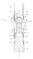
- the power transmission member 9 that transmits the rotational driving force from the rotational driving unit 8 to the rotational joint 15 is constituted by a torque tube 18 as shown in FIG.
- the insertion portion 10 and the first joint member 12 are both configured to be hollow. As shown in FIG. 3, the torque tube 18 passes through the hollow bending joint 13 from the insertion portion 10 to the second joint member 14. It is arranged extending to the vicinity.
- the torque tube 18 is a hollow tube having flexibility, and a wire (not shown) can be passed through the torque tube 18. The wire is used to actuate the end effector 6 fixed to the second joint member 14.
- the speed reduction unit 11 includes an input side gear 19 fixed to the tip of the torque tube 18 and an output side gear 20 fixed to the second joint member 14.
- the input side gear 19 is, for example, an external gear.
- the output gear 20 is an internal gear formed on the inner surface of the cylinder, for example.
- the input side gear 19 and the output side gear 20 are arranged eccentrically with their rotational axes parallel to each other and mesh with each other.
- the number of teeth of the input side gear 19 (for example, 8) is smaller than the number of teeth of the output side gear 20 (for example, 10).
- the rotation speed of the output side gear 20 is decelerated by a reduction ratio determined by the ratio of the number of teeth to the rotation speed of the input side gear 19.
- the pitch circle radius R 1 of the output side gear 20 formed on the inner surface of the cylinder is larger than the pitch circle radius R 2 of the input side gear 19, and the fitting formed on the first joint member 12.
- the input side gear 19 is supported by the hole 12b so as to be eccentric with the output side gear 20 in one radial direction and always meshed.
- the second joint member 14 is rotatably fitted in a cylindrical cover member 21 fixed to the first joint member 12.
- a circumferential groove 22 is formed in the second joint member 14, and is fixed so as to penetrate the cover member 21 in the radial direction so that the pin 23 is protruded into the circumferential groove 22 so as not to be removed in the first axis X direction. Is retained.
- the channel of the insertion part of the endoscope inserted into the body cavity from the outside of the patient P is related to the present embodiment.
- the medical manipulator 3 is inserted from the end effector 6 side of the distal end, and the end effector 6 and the movable portion 7 are projected from the opening of the channel on the distal end surface of the insertion portion of the endoscope disposed in the body.
- the control unit 4 controls the rotation drive unit 8 according to the operation input to move.
- Part 7 is activated.
- the end effector 6 is swung around the second axis Y, and the posture is changed. Further, the end effector 6 is rotated around the first axis X by operating the rotary joint 15.
- the end effector 6 has a grip portion 25 that can open and close the pair of grip pieces 24 a and 24 b, the opening and closing direction of the grip pieces 24 a and 24 b can be changed by the operation of the rotary joint 15.
- the rotational driving force generated in the rotational driving unit 8 is disposed through the hollow portions 10a and 12a provided in the insertion unit 10 and the first joint member 12.
- the input side gear 19 which is transmitted by the torque tube 18 and meshes with the output side gear 20 fixed to the second joint member 14 fixed to the end effector 6 is rotated. Since the number of teeth of the input side gear 19 is smaller than the number of teeth of the output side gear 20, the rotational driving force transmitted by the torque tube 18 is amplified according to the reduction ratio when transmitted to the output side gear 20, and the end The effector 6 is rotated.
- the speed reduction unit 11 is configured by the difference in the number of teeth between the input side gear 19 fixed to the tip of the torque tube 18 and the output side gear 20 fixed to the end effector 6. Therefore, even if the transmission efficiency in the torque tube 18 is reduced, the rotational driving force can be recovered in the speed reduction unit 11 and the end effector 6 can be rotated more reliably.
- the output side gear 20 has the internal teeth formed on the cylindrical inner surface, and therefore the input side gear 19 is meshed with the output side gear 20. Can be arranged. As a result, there is an advantage that the speed reduction part 11 can be reduced in diameter.
- the output side gear 20 is constituted by a cylindrical gear having internal teeth. However, if there is a margin in the outer diameter, a gear having external teeth on the outer surface of the cylinder is output side. You may employ
- the rotational driving force is transmitted by meshing between the input side gear 19 and the output side gear 20, but instead of this, as shown in FIG. 6, it is arranged on the outer periphery of the cylindrical input side rotating body 26.
- a structure in which a rotational driving force is transmitted by friction by bringing the friction surface 26 a into contact with the friction surface 27 a disposed on the inner periphery of the cylindrical output-side rotator 27 may be employed.
- the rotational driving force generated in the rotational drive unit 8 is transmitted by the torque tube 18, but instead, it is transmitted by the wire 17 as shown in FIGS. 7 and 8. You may decide to do it. 7 and 8, the spur gears 28 and 29 fixed to the end portions of the insertion portion 10 and the first joint member 12 are meshed with each other as the bending joint 13, and the spur gears 28 and 29 are parallel to each other. A so-called double joint system in which two axes are connected by a link member 30 is employed.
- first shafts 31 parallel to the axis Y of the bending joint 13 are arranged on the first joint member 12 of the rotary joint 15 disposed in front of the bending joint 13. , 32, 33 are provided.
- the most proximal first shaft 31 is disposed along the axis on the distal end side of the bending joint 13 and is D-cut.
- Two pulleys 16 and a first spur gear 34 are fixed to the first shaft 31 so as to be integrally rotatable by a D-cut.
- the first shaft 31 is not D-cut in the through holes 39 and 40 of the spur gear 29 and the link member 30, and is rotatable relative to the spur gear 29 and the link member 30.
- the wires 17 are wound around the two pulleys 16 in opposite directions, and the ends of the wires 17 are fixed to the pulleys 16. Thus, by pulling one of the wires 17 to the proximal end side, the corresponding pulley 16 is rotated in the reverse direction, and the first spur gear 34 is rotated in either direction via the first shaft 31. Can be done.
- a second spur gear 35 that meshes with the first spur gear 34 is fixed to the second shaft 32 adjacent to the first shaft 31.
- a third spur gear 36 that meshes with the second spur gear 35 and an input side gear 19 that is a spur gear that constitutes the speed reduction unit 11 are fixed to the third shaft 33 adjacent to the second shaft 32.
- a cylindrical output side gear 20 having a face gear 37 that meshes with the input side gear 19 is fixed to the second joint member 14 of the rotary joint 15.
- the link member 30 is provided with a fixing portion 41 that fixes a wire 42 separate from the wire 17 on both sides of the swing direction of the link member 30.
- the link member 30 is swung around the shaft 43 with respect to the insertion portion 10, thereby the first around the first shaft 31 with respect to the link member 30.
- the joint member 12 can be swung so that the bending joint 13 can be bent.
- the power transmission member 38 that transmits the rotational driving force generated by the rotational driving unit 8 is configured by the wire 17, the pulley 16, and the first spur gear 34 to the third spur gear 36.
- the input side gear 19 is rotationally driven by the rotational driving force transmitted by the above.
- the speed reduction unit 11 transmits the rotational driving force while reducing the speed between the gears 19 and 20 that rotate around the parallel axes.
- they are orthogonal to each other.
- the rotational driving force is transmitted while decelerating between the spur gear 19 and the face gear 37 that rotate around the axis.
- the method of transmitting power between the mutually orthogonal axes is not limited to the combination of the spur gear 19 and the face gear 37, and the helical gear, the face gear 37, the helical gears, etc. Can be adopted.
Abstract
Description
これらの外科用処置具によれば、屈曲関節を作動させて把持部の姿勢を変更し、把持対象物(縫い針等)を把持部で挟んだ後に、回転関節を作動させて把持部を回転させることで、把持した把持対象物が回転させられる。 2. Description of the Related Art A surgical treatment tool is known that has a rotary joint at the tip of a bending joint and rotates a gripping part supported by the rotary joint around its axis (see, for example,
According to these surgical treatment tools, the bending joint is operated to change the posture of the gripping part, and after gripping an object (sewing needle, etc.) between the gripping parts, the rotary joint is operated to rotate the gripping part. By doing so, the grasped object to be grasped is rotated.
このようにすることで、入力側歯車の歯数と出力側歯車の歯数との比により減速比が決定され、入力側歯車により伝達される回転駆動力を出力側歯車との噛み合いによって増幅し、出力側歯車に固定されたエンドエフェクタを第1軸線回りに容易に回転させることができる。 In the above aspect, the speed reduction unit includes an input side gear provided in the power transmission member, and an output side gear fixed to the end effector so as to be rotatable about the first axis and meshing with the input side gear. The number of teeth of the output side gear may be larger than the number of teeth of the input side gear.
By doing so, the reduction ratio is determined by the ratio of the number of teeth of the input side gear and the number of teeth of the output side gear, and the rotational driving force transmitted by the input side gear is amplified by meshing with the output side gear. The end effector fixed to the output side gear can be easily rotated around the first axis.
このようにすることで、動力伝達部材によって伝達されてきた回転駆動力を互いに平行な軸線回りに回転する入力側歯車から出力側歯車に伝達することができる。回転方向の変換を伴わないので、比較的細径に回転数を減速し、回転駆動力を増幅することができる。 In the above aspect, the input-side gear may be provided so as to be rotatable around an axis parallel to the first axis.
By doing in this way, the rotational driving force transmitted by the power transmission member can be transmitted from the input side gear rotating around the mutually parallel axes to the output side gear. Since the rotation direction is not changed, the rotational speed can be reduced to a relatively small diameter, and the rotational driving force can be amplified.
このようにすることで、屈曲関節の曲げによって、可撓性を有するトルクチューブが湾曲させられることにより、トルクチューブと周囲の部材との摩擦が増大して回転駆動力の伝達効率が低下するが、トルクチューブの先端に固定された入力側歯車と出力側歯車とを備える減速部によって、回転駆動力が増大させられるので、摩擦によって失われた回転駆動力が減速部によって回復され、高いトルクで回転関節を駆動することができる。 In the above aspect, the power transmission member is flexible and includes a torque tube disposed through the bending joint, and the input side gear is fixed to the tip of the torque tube. Also good.
By doing this, the flexible torque tube is bent by bending of the bending joint, so that the friction between the torque tube and the surrounding members increases and the transmission efficiency of the rotational driving force decreases. Since the rotational drive force is increased by the speed reduction unit having the input side gear and the output side gear fixed to the tip of the torque tube, the rotational drive force lost due to friction is recovered by the speed reduction unit, and the torque is high. The rotary joint can be driven.
本実施形態に係る医療用マニピュレータ3は、例えば、図1に示される医療用マニピュレータシステム1において用いられる。この医療用マニピュレータシステム1は、操作者Aにより操作される操作入力装置2と、患者Pの体腔内に挿入される医療用マニピュレータ3と、操作入力装置2への操作入力に基づいて医療用マニピュレータ3を制御する制御部4と、モニタ5とを備えている。 A
The
トルクチューブ18は、可撓性を有する中空のチューブであり、内部に、図示しないワイヤを貫通させることができるようになっている。ワイヤは第2関節部材14に固定されるエンドエフェクタ6を作動させるために使用される。 The
The
本実施形態に係る医療用マニピュレータシステム1を用いて体内の患部を処置するには、患者Pの体外から体腔内に挿入された内視鏡の挿入部のチャネルを介して、本実施形態に係る医療用マニピュレータ3を先端のエンドエフェクタ6側から挿入していき、体内に配置されている内視鏡の挿入部の先端面のチャネルの開口からエンドエフェクタ6および可動部7を突出させる。 The operation of the
In order to treat the affected part in the body using the
エンドエフェクタ6が一対の把持片24a,24bを開閉可能な把持部25を有する場合には、回転関節15の作動により把持片24a,24bの開閉方向を変更することができるようになっている。 In a state where the
When the
また、入力側歯車19と出力側歯車20との噛み合いによって回転駆動力を伝達しているが、これに代えて、図6に示されるように、円柱状の入力側回転体26の外周に配置された摩擦面26aを、円筒状の出力側回転体27の内周に配置された摩擦面27aに接触させることにより、摩擦によって回転駆動力を伝達する構造のものを採用してもよい。 In this embodiment, the
Further, the rotational driving force is transmitted by meshing between the
回転関節15の第2関節部材14には、入力側歯車19に噛み合うフェースギヤ37を備えた円筒状の出力側歯車20が固定されている。 A
A cylindrical
6 エンドエフェクタ
8 回転駆動部(駆動部)
9,38 動力伝達部材
11 減速部
13 屈曲関節
15 回転関節
16 プーリ
17 ワイヤ
18 トルクチューブ
19 入力側歯車
20 出力側歯車
26 入力側回転体
26a,27a 摩擦面
27 出力側回転体
X 第1軸線
Y 第2軸線 3
9, 38
Claims (6)
- 先端に配置されるエンドエフェクタを第1軸線回りに回転させる回転関節と、
該回転関節の基端側に配置され、前記エンドエフェクタを前記第1軸線に交差する第2軸線回りに揺動させる屈曲関節と、
回転駆動力を発生する駆動部と、
該駆動部により発生した回転駆動力を、前記屈曲関節を貫通して前記回転関節側に伝達する動力伝達部材と、
該動力伝達部材により伝達されてきた回転駆動力を、減速して前記エンドエフェクタに伝達する減速部とを備える医療用マニピュレータ。 A rotary joint that rotates an end effector disposed at the tip about a first axis;
A bending joint disposed on the proximal end side of the rotary joint and swinging the end effector about a second axis intersecting the first axis;
A driving unit for generating a rotational driving force;
A power transmission member that transmits the rotational driving force generated by the driving unit to the rotational joint side through the bending joint;
A medical manipulator comprising: a speed reduction unit that decelerates and transmits the rotational driving force transmitted by the power transmission member to the end effector. - 前記減速部が、前記動力伝達部材に設けられた入力側歯車と、前記エンドエフェクタに前記第1軸線回りに回転可能に固定され前記入力側歯車に噛み合う出力側歯車とを備え、
該出力側歯車の歯数が前記入力側歯車の歯数よりも多い請求項1に記載の医療用マニピュレータ。 The speed reduction portion includes an input side gear provided on the power transmission member, and an output side gear fixed to the end effector so as to be rotatable about the first axis and meshing with the input side gear;
The medical manipulator according to claim 1, wherein the number of teeth of the output side gear is greater than the number of teeth of the input side gear. - 前記入力側歯車が、前記第1軸線に平行な軸線回りに回転可能に設けられている請求項2に記載の医療用マニピュレータ。 The medical manipulator according to claim 2, wherein the input side gear is provided so as to be rotatable around an axis parallel to the first axis.
- 前記動力伝達部材が、前記駆動部により牽引されて張力を伝達するワイヤと、該ワイヤの張力により前記第2軸線に平行な軸線回りに回転可能に設けられたプーリとを備え、
前記入力側歯車が、前記プーリの回転により前記第2軸線に平行な軸線回りに回転させられる請求項2に記載の医療用マニピュレータ。 The power transmission member includes a wire that is pulled by the drive unit to transmit tension, and a pulley that is provided so as to be rotatable about an axis parallel to the second axis by the tension of the wire.
The medical manipulator according to claim 2, wherein the input side gear is rotated around an axis parallel to the second axis by rotation of the pulley. - 前記動力伝達部材が可撓性を有し、前記屈曲関節を貫通して配置されるトルクチューブからなり、
前記入力側歯車が、前記トルクチューブの先端に固定されている請求項2または請求項3に記載の医療用マニピュレータ。 The power transmission member is flexible and comprises a torque tube disposed through the bending joint;
The medical manipulator according to claim 2 or 3, wherein the input side gear is fixed to a tip of the torque tube. - 前記減速部が、前記動力伝達部材に設けられた入力側回転体と、前記エンドエフェクタに固定され前記入力側回転体との間で摩擦により回転駆動力を伝達する出力側回転体とを備え、
該出力側回転体の摩擦面の径寸法が、前記入力側回転体の摩擦面の径寸法より大きい請求項1に記載の医療用マニピュレータ。 The speed reduction unit includes an input-side rotator provided on the power transmission member, and an output-side rotator that is fixed to the end effector and transmits a rotational driving force by friction with the input-side rotator.
The medical manipulator according to claim 1, wherein the diameter of the friction surface of the output-side rotating body is larger than the diameter of the friction surface of the input-side rotating body.
Priority Applications (5)
| Application Number | Priority Date | Filing Date | Title |
|---|---|---|---|
| JP2017512180A JP6498281B2 (en) | 2015-04-17 | 2015-04-17 | Medical manipulator |
| DE112015005922.9T DE112015005922T5 (en) | 2015-04-17 | 2015-04-17 | Medical manipulator |
| CN201580078667.6A CN107530135A (en) | 2015-04-17 | 2015-04-17 | Medical manipulator |
| PCT/JP2015/061903 WO2016166898A1 (en) | 2015-04-17 | 2015-04-17 | Medical manipulator |
| US15/665,462 US20170325905A1 (en) | 2015-04-17 | 2017-08-01 | Medical manipulator |
Applications Claiming Priority (1)
| Application Number | Priority Date | Filing Date | Title |
|---|---|---|---|
| PCT/JP2015/061903 WO2016166898A1 (en) | 2015-04-17 | 2015-04-17 | Medical manipulator |
Related Child Applications (1)
| Application Number | Title | Priority Date | Filing Date |
|---|---|---|---|
| US15/665,462 Continuation US20170325905A1 (en) | 2015-04-17 | 2017-08-01 | Medical manipulator |
Publications (1)
| Publication Number | Publication Date |
|---|---|
| WO2016166898A1 true WO2016166898A1 (en) | 2016-10-20 |
Family
ID=57125799
Family Applications (1)
| Application Number | Title | Priority Date | Filing Date |
|---|---|---|---|
| PCT/JP2015/061903 WO2016166898A1 (en) | 2015-04-17 | 2015-04-17 | Medical manipulator |
Country Status (5)
| Country | Link |
|---|---|
| US (1) | US20170325905A1 (en) |
| JP (1) | JP6498281B2 (en) |
| CN (1) | CN107530135A (en) |
| DE (1) | DE112015005922T5 (en) |
| WO (1) | WO2016166898A1 (en) |
Cited By (3)
| Publication number | Priority date | Publication date | Assignee | Title |
|---|---|---|---|---|
| WO2018185897A1 (en) * | 2017-04-05 | 2018-10-11 | オリンパス株式会社 | Medical treatment instrument |
| WO2018220844A1 (en) * | 2017-06-02 | 2018-12-06 | オリンパス株式会社 | Power transmission mechanism and treatment tool |
| WO2019116415A1 (en) * | 2017-12-11 | 2019-06-20 | オリンパス株式会社 | Power transmission mechanism and surgical tool |
Families Citing this family (4)
| Publication number | Priority date | Publication date | Assignee | Title |
|---|---|---|---|---|
| JP6049585B2 (en) * | 2013-10-31 | 2016-12-21 | オリンパス株式会社 | Surgical tool |
| JP5980764B2 (en) * | 2013-11-29 | 2016-08-31 | オリンパス株式会社 | Surgical tool |
| WO2019220735A1 (en) * | 2018-05-16 | 2019-11-21 | オリンパス株式会社 | Driving-force transmission mechanism of endoscope |
| JP6777694B2 (en) | 2018-08-28 | 2020-10-28 | 株式会社メディカロイド | Endoscope adapter |
Citations (6)
| Publication number | Priority date | Publication date | Assignee | Title |
|---|---|---|---|---|
| US20050216033A1 (en) * | 2001-02-15 | 2005-09-29 | Endo Via Medical Inc. | Robotically controlled medical instrument with a flexible section |
| JP2010012087A (en) * | 2008-07-04 | 2010-01-21 | Toshiba Corp | Manipulator system and control method of manipulator |
| JP2010221043A (en) * | 1998-11-23 | 2010-10-07 | Microdexterity Systems Inc | Device for manipulating medical tool in patient's body |
| JP2011052805A (en) * | 2009-09-04 | 2011-03-17 | Univ Of Tokyo | Manipulator, and manipulation device using the same |
| JP2011206191A (en) * | 2010-03-29 | 2011-10-20 | Terumo Corp | Medical manipulator |
| JP2012096010A (en) * | 2010-11-02 | 2012-05-24 | Tyco Healthcare Group Lp | Adapter for powered surgical device |
Family Cites Families (2)
| Publication number | Priority date | Publication date | Assignee | Title |
|---|---|---|---|---|
| US6676684B1 (en) * | 2001-09-04 | 2004-01-13 | Intuitive Surgical, Inc. | Roll-pitch-roll-yaw surgical tool |
| JP4755047B2 (en) * | 2006-08-08 | 2011-08-24 | テルモ株式会社 | Working mechanism and manipulator |
-
2015
- 2015-04-17 DE DE112015005922.9T patent/DE112015005922T5/en not_active Withdrawn
- 2015-04-17 WO PCT/JP2015/061903 patent/WO2016166898A1/en active Application Filing
- 2015-04-17 JP JP2017512180A patent/JP6498281B2/en active Active
- 2015-04-17 CN CN201580078667.6A patent/CN107530135A/en active Pending
-
2017
- 2017-08-01 US US15/665,462 patent/US20170325905A1/en not_active Abandoned
Patent Citations (6)
| Publication number | Priority date | Publication date | Assignee | Title |
|---|---|---|---|---|
| JP2010221043A (en) * | 1998-11-23 | 2010-10-07 | Microdexterity Systems Inc | Device for manipulating medical tool in patient's body |
| US20050216033A1 (en) * | 2001-02-15 | 2005-09-29 | Endo Via Medical Inc. | Robotically controlled medical instrument with a flexible section |
| JP2010012087A (en) * | 2008-07-04 | 2010-01-21 | Toshiba Corp | Manipulator system and control method of manipulator |
| JP2011052805A (en) * | 2009-09-04 | 2011-03-17 | Univ Of Tokyo | Manipulator, and manipulation device using the same |
| JP2011206191A (en) * | 2010-03-29 | 2011-10-20 | Terumo Corp | Medical manipulator |
| JP2012096010A (en) * | 2010-11-02 | 2012-05-24 | Tyco Healthcare Group Lp | Adapter for powered surgical device |
Cited By (6)
| Publication number | Priority date | Publication date | Assignee | Title |
|---|---|---|---|---|
| WO2018185897A1 (en) * | 2017-04-05 | 2018-10-11 | オリンパス株式会社 | Medical treatment instrument |
| JPWO2018185897A1 (en) * | 2017-04-05 | 2020-03-05 | オリンパス株式会社 | Medical treatment tools |
| WO2018220844A1 (en) * | 2017-06-02 | 2018-12-06 | オリンパス株式会社 | Power transmission mechanism and treatment tool |
| WO2019116415A1 (en) * | 2017-12-11 | 2019-06-20 | オリンパス株式会社 | Power transmission mechanism and surgical tool |
| JPWO2019116415A1 (en) * | 2017-12-11 | 2020-11-19 | オリンパス株式会社 | Power transmission mechanism and treatment tool |
| US11627976B2 (en) | 2017-12-11 | 2023-04-18 | Olympus Corporation | Force transmission mechanism and instrument |
Also Published As
| Publication number | Publication date |
|---|---|
| US20170325905A1 (en) | 2017-11-16 |
| CN107530135A (en) | 2018-01-02 |
| JPWO2016166898A1 (en) | 2018-02-08 |
| JP6498281B2 (en) | 2019-04-10 |
| DE112015005922T5 (en) | 2017-09-21 |
Similar Documents
| Publication | Publication Date | Title |
|---|---|---|
| JP6498281B2 (en) | Medical manipulator | |
| JP6714101B2 (en) | Medical treatment tool | |
| WO2018179140A1 (en) | Medical treatment instrument | |
| JP6153484B2 (en) | Wire drive device and manipulator | |
| CN107708597B (en) | Robot for operation | |
| JP6230430B2 (en) | Surgical instrument and medical manipulator system | |
| JP2004532704A5 (en) | ||
| WO2016136676A1 (en) | Medical treatment instrument | |
| JP2007301692A (en) | Manipulator | |
| WO2015064692A1 (en) | Surgical tool | |
| US10004524B2 (en) | Instrument for carrying out medical interventions | |
| JP6153692B2 (en) | Medical manipulator | |
| JP2012081010A (en) | Endoscope and hardness adjusting device | |
| WO2015174213A1 (en) | Adapter for instrument and manipulator system for operation | |
| JP6634800B2 (en) | Joint mechanism and manipulator using the same | |
| WO2014007113A1 (en) | Medical manipulator | |
| US10736617B2 (en) | Force transmission mechanism for medical device and medical device | |
| WO2021065848A1 (en) | Elongate medical device | |
| CN211723295U (en) | Anastomat end effector, deflection device thereof and anastomat adopting deflection device | |
| WO2018185897A1 (en) | Medical treatment instrument | |
| WO2021176654A1 (en) | Endoscope treatment tool | |
| JP2017104968A (en) | Manipulator and multi-fingered hand device | |
| JP7066875B2 (en) | Gripping mechanism | |
| WO2017126100A1 (en) | Medical instrument | |
| WO2012104946A1 (en) | Dental handpiece |
Legal Events
| Date | Code | Title | Description |
|---|---|---|---|
| 121 | Ep: the epo has been informed by wipo that ep was designated in this application |
Ref document number: 15889235 Country of ref document: EP Kind code of ref document: A1 |
|
| ENP | Entry into the national phase |
Ref document number: 2017512180 Country of ref document: JP Kind code of ref document: A |
|
| WWE | Wipo information: entry into national phase |
Ref document number: 112015005922 Country of ref document: DE |
|
| 122 | Ep: pct application non-entry in european phase |
Ref document number: 15889235 Country of ref document: EP Kind code of ref document: A1 |