WO2016163423A1 - Ceramic honeycomb structural body and electrically heated catalyst - Google Patents
Ceramic honeycomb structural body and electrically heated catalyst Download PDFInfo
- Publication number
- WO2016163423A1 WO2016163423A1 PCT/JP2016/061304 JP2016061304W WO2016163423A1 WO 2016163423 A1 WO2016163423 A1 WO 2016163423A1 JP 2016061304 W JP2016061304 W JP 2016061304W WO 2016163423 A1 WO2016163423 A1 WO 2016163423A1
- Authority
- WO
- WIPO (PCT)
- Prior art keywords
- cells
- honeycomb structure
- ceramic honeycomb
- wall
- concentric layer
- Prior art date
Links
- 239000000919 ceramic Substances 0.000 title claims description 71
- 239000003054 catalyst Substances 0.000 title claims description 24
- 230000008602 contraction Effects 0.000 abstract description 4
- 230000037361 pathway Effects 0.000 abstract 2
- 239000007789 gas Substances 0.000 description 9
- 238000000746 purification Methods 0.000 description 8
- 230000002093 peripheral effect Effects 0.000 description 7
- MWUXSHHQAYIFBG-UHFFFAOYSA-N Nitric oxide Chemical compound O=[N] MWUXSHHQAYIFBG-UHFFFAOYSA-N 0.000 description 6
- 238000010438 heat treatment Methods 0.000 description 3
- 238000004519 manufacturing process Methods 0.000 description 3
- KDLHZDBZIXYQEI-UHFFFAOYSA-N Palladium Chemical compound [Pd] KDLHZDBZIXYQEI-UHFFFAOYSA-N 0.000 description 2
- 230000000694 effects Effects 0.000 description 2
- BASFCYQUMIYNBI-UHFFFAOYSA-N platinum Chemical compound [Pt] BASFCYQUMIYNBI-UHFFFAOYSA-N 0.000 description 2
- HBMJWWWQQXIZIP-UHFFFAOYSA-N silicon carbide Chemical compound [Si+]#[C-] HBMJWWWQQXIZIP-UHFFFAOYSA-N 0.000 description 2
- 229910010271 silicon carbide Inorganic materials 0.000 description 2
- 239000007787 solid Substances 0.000 description 2
- 239000004215 Carbon black (E152) Substances 0.000 description 1
- UGFAIRIUMAVXCW-UHFFFAOYSA-N Carbon monoxide Chemical compound [O+]#[C-] UGFAIRIUMAVXCW-UHFFFAOYSA-N 0.000 description 1
- 230000004913 activation Effects 0.000 description 1
- PNEYBMLMFCGWSK-UHFFFAOYSA-N aluminium oxide Inorganic materials [O-2].[O-2].[O-2].[Al+3].[Al+3] PNEYBMLMFCGWSK-UHFFFAOYSA-N 0.000 description 1
- 229910002091 carbon monoxide Inorganic materials 0.000 description 1
- 238000006555 catalytic reaction Methods 0.000 description 1
- 229910052878 cordierite Inorganic materials 0.000 description 1
- JSKIRARMQDRGJZ-UHFFFAOYSA-N dimagnesium dioxido-bis[(1-oxido-3-oxo-2,4,6,8,9-pentaoxa-1,3-disila-5,7-dialuminabicyclo[3.3.1]nonan-7-yl)oxy]silane Chemical compound [Mg++].[Mg++].[O-][Si]([O-])(O[Al]1O[Al]2O[Si](=O)O[Si]([O-])(O1)O2)O[Al]1O[Al]2O[Si](=O)O[Si]([O-])(O1)O2 JSKIRARMQDRGJZ-UHFFFAOYSA-N 0.000 description 1
- 238000006073 displacement reaction Methods 0.000 description 1
- 238000005485 electric heating Methods 0.000 description 1
- 229930195733 hydrocarbon Natural products 0.000 description 1
- 150000002430 hydrocarbons Chemical class 0.000 description 1
- 230000004048 modification Effects 0.000 description 1
- 238000012986 modification Methods 0.000 description 1
- 229910052763 palladium Inorganic materials 0.000 description 1
- 238000005192 partition Methods 0.000 description 1
- 229910052697 platinum Inorganic materials 0.000 description 1
- 239000000126 substance Substances 0.000 description 1
Images


Classifications
-
- F—MECHANICAL ENGINEERING; LIGHTING; HEATING; WEAPONS; BLASTING
- F01—MACHINES OR ENGINES IN GENERAL; ENGINE PLANTS IN GENERAL; STEAM ENGINES
- F01N—GAS-FLOW SILENCERS OR EXHAUST APPARATUS FOR MACHINES OR ENGINES IN GENERAL; GAS-FLOW SILENCERS OR EXHAUST APPARATUS FOR INTERNAL COMBUSTION ENGINES
- F01N3/00—Exhaust or silencing apparatus having means for purifying, rendering innocuous, or otherwise treating exhaust
- F01N3/08—Exhaust or silencing apparatus having means for purifying, rendering innocuous, or otherwise treating exhaust for rendering innocuous
- F01N3/10—Exhaust or silencing apparatus having means for purifying, rendering innocuous, or otherwise treating exhaust for rendering innocuous by thermal or catalytic conversion of noxious components of exhaust
- F01N3/24—Exhaust or silencing apparatus having means for purifying, rendering innocuous, or otherwise treating exhaust for rendering innocuous by thermal or catalytic conversion of noxious components of exhaust characterised by constructional aspects of converting apparatus
- F01N3/28—Construction of catalytic reactors
- F01N3/2803—Construction of catalytic reactors characterised by structure, by material or by manufacturing of catalyst support
- F01N3/2825—Ceramics
- F01N3/2828—Ceramic multi-channel monoliths, e.g. honeycombs
-
- B—PERFORMING OPERATIONS; TRANSPORTING
- B01—PHYSICAL OR CHEMICAL PROCESSES OR APPARATUS IN GENERAL
- B01D—SEPARATION
- B01D53/00—Separation of gases or vapours; Recovering vapours of volatile solvents from gases; Chemical or biological purification of waste gases, e.g. engine exhaust gases, smoke, fumes, flue gases, aerosols
- B01D53/34—Chemical or biological purification of waste gases
- B01D53/92—Chemical or biological purification of waste gases of engine exhaust gases
- B01D53/94—Chemical or biological purification of waste gases of engine exhaust gases by catalytic processes
- B01D53/9445—Simultaneously removing carbon monoxide, hydrocarbons or nitrogen oxides making use of three-way catalysts [TWC] or four-way-catalysts [FWC]
- B01D53/9454—Simultaneously removing carbon monoxide, hydrocarbons or nitrogen oxides making use of three-way catalysts [TWC] or four-way-catalysts [FWC] characterised by a specific device
-
- B—PERFORMING OPERATIONS; TRANSPORTING
- B01—PHYSICAL OR CHEMICAL PROCESSES OR APPARATUS IN GENERAL
- B01J—CHEMICAL OR PHYSICAL PROCESSES, e.g. CATALYSIS OR COLLOID CHEMISTRY; THEIR RELEVANT APPARATUS
- B01J23/00—Catalysts comprising metals or metal oxides or hydroxides, not provided for in group B01J21/00
- B01J23/38—Catalysts comprising metals or metal oxides or hydroxides, not provided for in group B01J21/00 of noble metals
- B01J23/40—Catalysts comprising metals or metal oxides or hydroxides, not provided for in group B01J21/00 of noble metals of the platinum group metals
-
- B01J35/33—
-
- B01J35/56—
-
- B—PERFORMING OPERATIONS; TRANSPORTING
- B01—PHYSICAL OR CHEMICAL PROCESSES OR APPARATUS IN GENERAL
- B01J—CHEMICAL OR PHYSICAL PROCESSES, e.g. CATALYSIS OR COLLOID CHEMISTRY; THEIR RELEVANT APPARATUS
- B01J37/00—Processes, in general, for preparing catalysts; Processes, in general, for activation of catalysts
- B01J37/02—Impregnation, coating or precipitation
- B01J37/0215—Coating
-
- F—MECHANICAL ENGINEERING; LIGHTING; HEATING; WEAPONS; BLASTING
- F01—MACHINES OR ENGINES IN GENERAL; ENGINE PLANTS IN GENERAL; STEAM ENGINES
- F01N—GAS-FLOW SILENCERS OR EXHAUST APPARATUS FOR MACHINES OR ENGINES IN GENERAL; GAS-FLOW SILENCERS OR EXHAUST APPARATUS FOR INTERNAL COMBUSTION ENGINES
- F01N3/00—Exhaust or silencing apparatus having means for purifying, rendering innocuous, or otherwise treating exhaust
- F01N3/08—Exhaust or silencing apparatus having means for purifying, rendering innocuous, or otherwise treating exhaust for rendering innocuous
- F01N3/10—Exhaust or silencing apparatus having means for purifying, rendering innocuous, or otherwise treating exhaust for rendering innocuous by thermal or catalytic conversion of noxious components of exhaust
- F01N3/18—Exhaust or silencing apparatus having means for purifying, rendering innocuous, or otherwise treating exhaust for rendering innocuous by thermal or catalytic conversion of noxious components of exhaust characterised by methods of operation; Control
- F01N3/20—Exhaust or silencing apparatus having means for purifying, rendering innocuous, or otherwise treating exhaust for rendering innocuous by thermal or catalytic conversion of noxious components of exhaust characterised by methods of operation; Control specially adapted for catalytic conversion ; Methods of operation or control of catalytic converters
- F01N3/2006—Periodically heating or cooling catalytic reactors, e.g. at cold starting or overheating
- F01N3/2013—Periodically heating or cooling catalytic reactors, e.g. at cold starting or overheating using electric or magnetic heating means
- F01N3/2026—Periodically heating or cooling catalytic reactors, e.g. at cold starting or overheating using electric or magnetic heating means directly electrifying the catalyst substrate, i.e. heating the electrically conductive catalyst substrate by joule effect
-
- F—MECHANICAL ENGINEERING; LIGHTING; HEATING; WEAPONS; BLASTING
- F01—MACHINES OR ENGINES IN GENERAL; ENGINE PLANTS IN GENERAL; STEAM ENGINES
- F01N—GAS-FLOW SILENCERS OR EXHAUST APPARATUS FOR MACHINES OR ENGINES IN GENERAL; GAS-FLOW SILENCERS OR EXHAUST APPARATUS FOR INTERNAL COMBUSTION ENGINES
- F01N3/00—Exhaust or silencing apparatus having means for purifying, rendering innocuous, or otherwise treating exhaust
- F01N3/08—Exhaust or silencing apparatus having means for purifying, rendering innocuous, or otherwise treating exhaust for rendering innocuous
- F01N3/10—Exhaust or silencing apparatus having means for purifying, rendering innocuous, or otherwise treating exhaust for rendering innocuous by thermal or catalytic conversion of noxious components of exhaust
- F01N3/24—Exhaust or silencing apparatus having means for purifying, rendering innocuous, or otherwise treating exhaust for rendering innocuous by thermal or catalytic conversion of noxious components of exhaust characterised by constructional aspects of converting apparatus
- F01N3/28—Construction of catalytic reactors
- F01N3/2803—Construction of catalytic reactors characterised by structure, by material or by manufacturing of catalyst support
-
- B—PERFORMING OPERATIONS; TRANSPORTING
- B01—PHYSICAL OR CHEMICAL PROCESSES OR APPARATUS IN GENERAL
- B01D—SEPARATION
- B01D2255/00—Catalysts
- B01D2255/10—Noble metals or compounds thereof
- B01D2255/102—Platinum group metals
- B01D2255/1021—Platinum
-
- B—PERFORMING OPERATIONS; TRANSPORTING
- B01—PHYSICAL OR CHEMICAL PROCESSES OR APPARATUS IN GENERAL
- B01D—SEPARATION
- B01D2255/00—Catalysts
- B01D2255/10—Noble metals or compounds thereof
- B01D2255/102—Platinum group metals
- B01D2255/1023—Palladium
-
- F—MECHANICAL ENGINEERING; LIGHTING; HEATING; WEAPONS; BLASTING
- F01—MACHINES OR ENGINES IN GENERAL; ENGINE PLANTS IN GENERAL; STEAM ENGINES
- F01N—GAS-FLOW SILENCERS OR EXHAUST APPARATUS FOR MACHINES OR ENGINES IN GENERAL; GAS-FLOW SILENCERS OR EXHAUST APPARATUS FOR INTERNAL COMBUSTION ENGINES
- F01N2240/00—Combination or association of two or more different exhaust treating devices, or of at least one such device with an auxiliary device, not covered by indexing codes F01N2230/00 or F01N2250/00, one of the devices being
- F01N2240/16—Combination or association of two or more different exhaust treating devices, or of at least one such device with an auxiliary device, not covered by indexing codes F01N2230/00 or F01N2250/00, one of the devices being an electric heater, i.e. a resistance heater
-
- F—MECHANICAL ENGINEERING; LIGHTING; HEATING; WEAPONS; BLASTING
- F01—MACHINES OR ENGINES IN GENERAL; ENGINE PLANTS IN GENERAL; STEAM ENGINES
- F01N—GAS-FLOW SILENCERS OR EXHAUST APPARATUS FOR MACHINES OR ENGINES IN GENERAL; GAS-FLOW SILENCERS OR EXHAUST APPARATUS FOR INTERNAL COMBUSTION ENGINES
- F01N2330/00—Structure of catalyst support or particle filter
- F01N2330/06—Ceramic, e.g. monoliths
-
- F—MECHANICAL ENGINEERING; LIGHTING; HEATING; WEAPONS; BLASTING
- F01—MACHINES OR ENGINES IN GENERAL; ENGINE PLANTS IN GENERAL; STEAM ENGINES
- F01N—GAS-FLOW SILENCERS OR EXHAUST APPARATUS FOR MACHINES OR ENGINES IN GENERAL; GAS-FLOW SILENCERS OR EXHAUST APPARATUS FOR INTERNAL COMBUSTION ENGINES
- F01N2330/00—Structure of catalyst support or particle filter
- F01N2330/30—Honeycomb supports characterised by their structural details
Definitions
- the present invention relates to a ceramic honeycomb structure and an electrically heated catalyst suitable for supporting a catalyst used in, for example, an automobile exhaust system.
- an electrically heated catalyst (Electrically Heated Catalyst: EHC) is known as an exhaust purification device that is provided on an exhaust path of an automobile or the like and purifies exhaust gas discharged from an engine.
- EHC Electrically heated Catalyst
- Such an EHC has a ceramic honeycomb structure on which a catalyst is supported and an electrode for energizing the ceramic honeycomb structure.
- Patent Document 1 discloses a ceramic honeycomb structure including cells arranged radially.
- the ceramic honeycomb structure 100 has a network structure composed of a plurality of gas conduction cells 101 and is accommodated in a cylindrical outer skin 102.
- the gas conduction cell 101 is formed as a radial cell, and is defined between a radial web 103 that is a radial direction of the outer skin 102 and a tangential web 104 that is parallel to the tangential direction of the outer skin 102.
- the ceramic honeycomb structure 100 is formed in a cylindrical shape by accommodating eight pieces produced in a fan shape in units of 45 degrees in the outer skin 102. Each piece is divided into a plurality of groups GRi ⁇ 1, GR, GRi + 1,...
- the radial web 103 is continuous in a straight line in the radial direction in each group GR. It should be noted that the radial webs 103 are not arranged in a straight line between the group GRs adjacent to each other in the radial direction.
- a ceramic honeycomb structure and an electrically heated catalyst capable of obtaining a sufficient strength against a compressive force and a tensile force generated by heat and a long current path along a radial direction.
- the purpose is to provide.
- a ceramic honeycomb structure of the present invention for solving the above-mentioned problems has a main body having a cylindrical outer wall, and a large number of cells that are partitioned inside the main body and are continuous along the longitudinal direction of the main body.
- Each cell is defined by a pair of arc walls concentric with the outer wall and a pair of straight walls along the radial direction of the outer wall, and the arc is cut in a cross section perpendicular to the longitudinal direction of the main body.
- the shortest radial path length between the outer wall and the center of the main body that passes through at least one of the wall and the straight wall is larger than the outer shell radial dimension that is the radius of the cylinder that is the outer shape of the main body.
- the main body may be provided with a cylindrical minimum member, for example, or may be provided with a cylindrical minimum member. That is, the center of the main body may be hollow or solid.
- a large number of cells are defined inside the main body having a cylindrical outer wall, and are continuous along the longitudinal direction of the main body.
- Each cell is defined by a pair of arc walls concentric with the outer wall and a pair of straight walls along the radial direction of the outer wall.
- the shortest radial path length between the center of the main body and the outer wall passing through at least one of the arc wall and the straight wall is larger than the outer shell radial dimension that is the radius of the cylinder that is the outer shape of the main body.
- the ceramic honeycomb structure of the present invention desirably has the following aspect. (1) Among the cells adjacent along the radial direction of the main body, the straight wall in one cell and the straight wall in the other cell are arranged so as not to be along the same plane. For this reason, since the inner cell and the outer cell adjacent to each other in the radial direction of the main body are displaced from each other, the straight wall is located in the middle of the arc wall, and the arrangement of each cell is not in a lattice shape.
- a first concentric layer portion and a second concentric layer portion having five or less concentric layers adjacent to each other along the radial direction of the main body, the first concentric layer portion and the second concentric layer portion are:
- the straight walls are arranged along the same plane, and the straight walls in the first concentric layer portion and the straight walls in the second concentric layer portion are arranged not to be along the same plane. . That is, the straight wall can be continuous in the same plane up to 5 layers in the radial direction, but not more than 6 layers. For this reason, since the straight wall is displaced between the first concentric layer portion and the second concentric layer portion, the entire cell arrangement is not in a lattice shape, and the strength can be ensured and the straight wall can be continued to some extent. Easy to manufacture.
- the center cell has a radius R, the curvature of the arc wall outside the concentric layer adjacent to the outside of the center cell is 1 / 3R, and the other adjacent to the outside of the concentric layer having a radius of 3R.
- the arc walls on the outer side of the concentric layers sequentially have radii of 5R, 7R, 9R,..., (2n-1) R. For this reason, the size and shape of the cells can be made uniform.
- the concentric layer adjacent to the outside of the center cell has 8 cells, and the other concentric layers adjacent to the outside of the concentric layer of 8 cells have 16 cells, 16 cells, and 24 cells in order,
- the other concentric layers outside the concentric layer of 24 cells have the same number of cells as the concentric layer inside the concentric layer, or the number of cells obtained by adding 8 to the number of cells in the concentric layer. For this reason, the size and shape of the cells can be made uniform.
- the ratio of the opening area of each cell in the concentric layer is 0.9 to 1.1, the opening area of each cell in the concentric layer, and the opening of each cell in another concentric layer adjacent to the outside
- the ratio to the area is 0.56 to 1.8. For this reason, the size and shape of the cells can be made uniform.
- the current heating type catalyst of the present invention for solving the above-mentioned problems is that the outer wall, the arc wall and the straight wall in the ceramic honeycomb structure are made of ceramics having conductivity, and the arc wall and A catalyst is supported on the surface of the straight wall, and a conductive electrode is connected to the ceramic honeycomb structure.
- the inner cell and the outer cell adjacent to each other in the radial direction of the main body are shifted from each other. Therefore, it is possible to obtain sufficient strength against compressive force and tensile force without greatly expanding or contracting in the radial direction.
- the inner cell and the outer cell are shifted from each other, the shortest radial path length between the center of the main body and the outer wall via the arc wall and the straight wall is increased, and the energization path is increased. And can be suitably used for an electrically heated catalyst (EHC).
- EHC electrically heated catalyst
- FIG. 1 is a cross-sectional view of an electrically heated catalyst (EHC) using a ceramic honeycomb structure according to the first embodiment of the present invention.
- EHC electrically heated catalyst
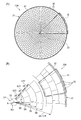
- 2A is a cross-sectional view cut perpendicularly to the longitudinal direction of the main body of the ceramic honeycomb structure
- FIG. 2B is an enlarged view of a “B” portion in FIG.
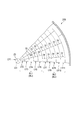
- FIG. 3 is an enlarged view of a “III” portion in FIG.
- FIG. 4 is a view corresponding to FIG. 2B of the ceramic honeycomb structure according to the second embodiment of the present invention.
- FIG. 5 is an enlarged cross-sectional view of a conventional ceramic honeycomb structure.
- a ceramic honeycomb structure of the present invention for solving the above-mentioned problems has a main body having a cylindrical outer wall, and a large number of cells that are partitioned inside the main body and are continuous along the longitudinal direction of the main body.
- Each cell is defined by a pair of arc walls concentric with the outer wall and a pair of straight walls along the radial direction of the outer wall, and the arc is cut in a cross section perpendicular to the longitudinal direction of the main body. It is larger than the outer shell radius dimension which is the radius of the cylinder which is the outer shape of the main body passing through at least one of the wall and the straight wall.
- a large number of cells are defined inside the main body having a cylindrical outer wall, and are continuous along the longitudinal direction of the main body.
- Each cell is defined by a pair of arc walls concentric with the outer wall and a pair of straight walls along the radial direction of the outer wall.
- the shortest radial path length between the center of the main body and the outer wall passing through at least one of the arc wall and the straight wall is larger than the outer shell radial dimension that is the radius of the cylinder that is the outer shape of the main body.
- the main body may be provided with a cylindrical minimum member, for example, or may be provided with a cylindrical minimum member. That is, the center of the main body may be hollow or solid.
- the ceramic honeycomb structure of the present invention desirably has the following aspect.
- a first concentric layer portion and a second concentric layer portion having five or less concentric layers adjacent to each other along the radial direction of the main body, the first concentric layer portion and the second concentric layer portion are:
- the straight walls are arranged along the same plane, and the straight walls in the first concentric layer portion and the straight walls in the second concentric layer portion are arranged not to be along the same plane. . That is, the straight wall can be continuous in the same plane up to 5 layers in the radial direction, but not more than 6 layers. For this reason, since the straight wall is displaced between the first concentric layer portion and the second concentric layer portion, the entire cell arrangement is not in a lattice shape, and the strength can be ensured and the straight wall can be continued to some extent. Easy to manufacture.
- the center cell has a radius R, the curvature of the arc wall outside the concentric layer adjacent to the outside of the center cell is 1 / 3R, and the other adjacent to the outside of the concentric layer having a radius of 3R.
- the arc walls on the outer side of the concentric layers sequentially have radii of 5R, 7R, 9R,..., (2n-1) R. For this reason, the size and shape of the cells can be made uniform.
- the concentric layer adjacent to the outside of the center cell has 8 cells, and the other concentric layers adjacent to the outside of the concentric layer of 8 cells have 16 cells, 16 cells, and 24 cells in order,
- the other concentric layers outside the concentric layer of 24 cells have the same number of cells as the concentric layer inside the concentric layer, or the number of cells obtained by adding 8 to the number of cells in the concentric layer. For this reason, the size and shape of the cells can be made uniform.
- the ratio of the opening area of each cell in the concentric layer is 0.9 to 1.1, the opening area of each cell in the concentric layer, and the opening of each cell in another concentric layer adjacent to the outside
- the ratio to the area is 0.56 to 1.8. For this reason, the size and shape of the cells can be made uniform.
- the current heating type catalyst of the present invention for solving the above-mentioned problems is that the outer wall, the arc wall and the straight wall in the ceramic honeycomb structure are made of ceramics having conductivity, and the arc wall and A catalyst is supported on the surface of the straight wall, and a conductive electrode is connected to the ceramic honeycomb structure.
- FIG. 1 shows an exhaust purification device 10A.
- This exhaust purification device 10A is an electrically heated catalyst (hereinafter referred to as “EHC”) that is provided on an exhaust path of an automobile or the like and purifies exhaust gas discharged from an engine.
- the exhaust purification device 10A includes a hollow case 11 forming an exterior, a ceramic honeycomb structure 20A housed in the case 11, electrodes 12 and 13 provided on the outer peripheral surface of the ceramic honeycomb structure 20A, and an electrode 12 , 13 are respectively connected to terminals 14, 15 electrically connected.
- the case 11 is a member that forms the exterior of the exhaust gas purification apparatus 10A and forms a part of an exhaust pipe through which exhaust gas discharged from the engine flows, and is formed in a substantially cylindrical shape.
- the ceramic honeycomb structure 20A is a porous member having a honeycomb structure made of ceramics such as SiC (silicon carbide) or cordierite, and supports a catalyst such as platinum or palladium.
- the ceramic honeycomb structure 20 ⁇ / b> A is formed in a cylindrical shape having an outer diameter slightly smaller than the inner diameter of the case 11, and a predetermined gap (inner peripheral surface of the case 11) between the case 11 and the inner peripheral surface of the case 11.
- the exhaust gas discharged from the engine is disposed so as to pass through the inside of the ceramic honeycomb structure 20A in the axial direction.
- a holding member (not shown) made of alumina or the like is provided between the inner peripheral surface of the case 11 and the outer peripheral surface of the ceramic honeycomb structure 20A to prevent the positional displacement of the ceramic honeycomb structure 20A.
- the gap between the inner peripheral surface of the case 11 and the outer peripheral surface of the ceramic honeycomb structure 20A is sealed.
- Such an exhaust purification apparatus 10A raises the temperature of the catalyst supported on the ceramic honeycomb structure 20A to the activation temperature by energizing and heating the ceramic honeycomb structure 20A between the electrodes 12 and 13 using a power source.
- the ceramic honeycomb structure 20A has a main body 21 including a cylindrical outer wall 22.
- a large number of cells 30 that are partitioned in the cross-sectional direction of the main body 21 and are continuous along the longitudinal direction of the main body 21 (the direction orthogonal to the plane of the paper in FIGS. 2A and 2B) are accommodated inside the main body 21.
- Each cell 30 is partitioned by a pair of arc walls 31 and 32 concentric with the outer wall 22 and a pair of straight walls 33 and 34 along the radial direction of the outer wall 22 (see FIG. 3).
- a center cell 301 having a radius R is disposed as a reference cell at the center 23 of the main body 21.
- the center cell 301 has a cylindrical shape and does not have a wall (partition) inside.
- a large number of concentric layers LYn are provided outside the center cell 301. Therefore, the center 23 of the main body 21 is hollow.
- the arc wall 31 outside the concentric layer LY2 adjacent to the outside of the center cell 301 has a curvature of 1 / 3R with the center 23 as the center. Further, in the other concentric layer LYn adjacent to the outside of the concentric layer LY2 having the radius 3R, the outer arc wall 31 has a radius of curvature of 5R, 7R, 9R,..., (2n ⁇ 1) R sequentially.
- the concentric layer LY2 adjacent to the outside of the center cell 301 has 8 cells, and the other concentric layers LYn adjacent to the outside of the 8-cell concentric layer LY2 have 16 cells, 16 cells, and 24 cells in sequence.
- the other concentric layers LYn + 1 outside the 24 concentric layers LYn have the same number of cells as the concentric layers LYn inside the concentric layers LYn + 1, or the number of cells obtained by adding 8 to the number of cells in the concentric layers LYn.
- the ratio of the opening area of any two cells 30 in the concentric layer LYn is preferably 0.9 to 1.1.
- the ratio of the opening area of each cell 30 in the concentric layer LYn to the opening area of each cell 30 in the other concentric layer LYn + 1 adjacent to the outside is preferably 0.56 to 1.8.
- the cell 30 has a partial arc shape (fan shape) having a certain width.
- the radial width W of the cell 30, that is, the length of the straight walls 33 and 34 is constant.
- W 2 ⁇ R.
- the circumferential length L (Li) of the cell 30 is a constant length on the same concentric circle. The length L can be calculated from the radius of the concentric layer LYn and the number of cells.
- the straight walls 33 and 34 in one cell 30 and the straight walls 33 and 34 in the other cell 30 are arranged so as not to be along the same plane.
- the straight walls 33 and 34 of the cells 30 adjacent to each other in the radial direction are arranged so as to be shifted in the circumferential direction, so that a so-called tear joint is arranged.
- a torn joint means a joint where every other vertical (vertical) connection is different, such as in masonry or brickwork. Excellent.
- the shortest radial path length R1 between the center 23 of the main body 21 and the outer wall 22 via the circular arc walls 31 and 32 and the straight walls 33 and 34 is an outer shape connecting the center 23 of the main body 21 and the outer wall 22. It becomes larger than the outer shell radius dimension R2 which is the radius of the cylinder. That is, the shortest radial direction path length R1 is equal to the length of the straight walls 33 and 34 connecting the center 23 of the main body 21 and the outer wall 22, and the length of the arc walls 31 and 32 corresponding to the deviation of the straight walls 33 and 34. (Corresponding to the outer shell radius dimension R2), it is larger than the outer shell radius dimension R2.
- a large number of cells 30 are partitioned inside the main body 21 having the cylindrical outer wall 22 and are continuous along the longitudinal direction of the main body 21.
- Each cell 30 is partitioned by a pair of arcuate walls 31 and 32 concentric with the outer wall 22 and a pair of straight walls 33 and 34 along the radial direction of the outer wall 22.
- the outer shell in which the shortest radial path length between the center 23 of the main body 21 and the outer wall 22 via the circular arc walls 31 and 32 and the straight walls 33 and 34 is the radius of the cylinder that is the outer shape of the main body 21. It becomes larger than the radial dimension. Thereby, since an energization path becomes long, it can use suitably for EHC, for example.
- the straight walls 33 and 34 in one cell 30 and the straight walls 33 and 34 in the other cell 30 are arranged so as not to be on the same plane. For this reason, since the inner cell 30 and the outer cell 30 adjacent to each other in the radial direction of the main body 21 are arranged so as to be shifted, the straight walls 33 and 34 are located in the middle of the arc walls 31 and 32, respectively.
- the arrangement of the cells 30 is not a grid.
- the main body 21 has a cylindrical center cell 301 at the center. If a wall is present at the center, the center cell 301 becomes a semicircular or sectional fan-shaped cell, which may have a different size from the other cells 30 or a different aspect ratio of the cell cross section.
- the center cell 301 located at the center is a circular cell concentric with the filter center, it is easy to match the size and aspect ratio with other cells.
- the center cell 301 has a radius R, and the curvature of the arc wall 31 outside the concentric layer LY2 adjacent to the outside of the center cell 301 is 1 / 3R. Further, the arc wall 31 outside the other concentric layer LYn adjacent to the outside of the concentric layer LY2 having the radius 3R has curvatures of radius 5R, 7R, 9R,..., (2n ⁇ 1) R sequentially. For this reason, the size and shape of the cell 30 can be made uniform.
- the concentric layer LY2 adjacent to the outside of the center cell 301 has 8 cells, and the other concentric layers LYn adjacent to the outside of the 8-cell concentric layer LY2 are successively 16
- the number of cells of the concentric layer LYn + 1 outside the concentric layer LYn of 24 cells is equal to the number of cells of the concentric layer LYn inside the concentric layer LYn + 1, or the number of cells of the concentric layer LYn. 8 plus the number of cells. For this reason, the size and shape of the cell 30 can be made uniform.
- the ratio of the opening area of each cell 30 in the concentric layer LYn is 0.9 to 1.1. That is, since the ratio of the opening areas of any two cells 30 in the same concentric layer LYn is 0.9 to 1.1, the size and shape of the cells 30 can be made uniform.
- the ratio between the opening area of each cell 30 in the concentric layer LYn and the opening area of each cell 30 in the other concentric layer LYn + 1 adjacent to the outside is 0.56 to 1. .8. For this reason, the size and shape of the cell 30 can be made uniform.
- the ceramic honeycomb structure 20 ⁇ / b> B has a plurality of concentric layers BLi having a plurality of concentric layers LYn along the radial direction of the main body 21.
- the center 23 side is defined as a first concentric layer portion BL1
- the outer side is defined as a second concentric layer portion BL2.
- Each of the first concentric layer portion BL1 and the second concentric layer portion BL2 has five or less concentric layers LYn.
- the straight walls 33 and 34 of each cell 30 are arranged along the same plane.
- the straight walls 33 and 34 are continuous in the radial direction.
- the straight walls 33 and 34 in the first concentric layer portion BL1 and the straight walls 33 and 34 in the second concentric layer portion BL2 are in the same plane. It is arranged so as not to follow.
- the first and second concentric layer portions BL1 and BL2 having five or less concentric layers LYn adjacent to each other along the radial direction of the main body 21 are provided.
- the straight walls 33 and 34 are arranged along the same plane, and the straight walls 33 and 34 in the first concentric layer portion BL1 and the second concentric layers It arrange
- the straight walls 33 and 34 can be continuous in the same plane up to five layers in the radial direction, but not more than six layers. For this reason, since the straight walls 33 and 34 are shifted between the first concentric layer portion BL1 and the second concentric layer portion BL2, the entire arrangement of the cells 30 is not in a lattice shape, ensuring strength and straightening to some extent. Since the walls 33 and 34 can be continuous, the manufacture becomes easy.
- the ceramic honeycomb structure and the electrically heated catalyst of the present invention are not limited to the above-described embodiments, and appropriate modifications and improvements can be made.
- the ceramic honeycomb structure and the electrically heated catalyst of the present invention can be used, for example, as a catalyst carrier in an automobile exhaust purification device.
Abstract
Inner cells (30) and outer cells (30) which are adjacent to one another in a radial direction of a main body (21) are arranged offset from one another, and therefore adequate strength with respect to compressive forces and tensile forces can be obtained without significant thermal expansion or contraction in the radial direction, even if the temperature rises or falls suddenly. Further, because the inner cells (30) and the outer cells (30) are disposed offset from one another, a minimum radial direction pathway length (R1) from the center (23) of the main body (21) to an outer wall (22) thereof via circular arc walls (31, 32) and straight-line walls (33, 34) is greater than an outer shell radial dimension (R2) of the main body (21). The electrical pathway is therefore increased, and this configuration can therefore be suitably used in an exhaust gas purifying device (10A), for example.
Description
本発明は、例えば自動車の排気系に用いられる触媒を担持するのに好適なセラミックハニカム構造体および通電加熱式触媒に関する。
The present invention relates to a ceramic honeycomb structure and an electrically heated catalyst suitable for supporting a catalyst used in, for example, an automobile exhaust system.
従来、自動車等の排気経路上に設けられ、エンジンから排出される排気ガスを浄化する排気浄化装置として通電加熱式触媒(Electrically Heated Catalyst:EHC)が知られている。このようなEHCは、触媒が担持されたセラミックハニカム構造体およびセラミックハニカム構造体に通電するための電極を有する。
Conventionally, an electrically heated catalyst (Electrically Heated Catalyst: EHC) is known as an exhaust purification device that is provided on an exhaust path of an automobile or the like and purifies exhaust gas discharged from an engine. Such an EHC has a ceramic honeycomb structure on which a catalyst is supported and an electrode for energizing the ceramic honeycomb structure.
特許文献1には、放射状に配列されたセルを備えたセラミックハニカム構造体が示されている。
図5に示すように、このセラミックハニカム構造体100は、複数のガス導通セル101からなる網状組織を呈しており、円筒状の外皮102の内部に収容されている。ガス導通セル101は、放射状セルとして形成されており、外皮102の半径方向である半径方向ウェブ103と、外皮102の接線方向と平行な接線方向ウェブ104との間に画成されている。
また、セラミックハニカム構造体100は、45度単位で扇形状に作製した8ピースを外皮102の内部に収容して円筒形状に形成されている。各ピースにおいては、半径方向に複数のグループGRi-1、GR、GRi+1、…に分かれており、各グループGR内では半径方向ウェブ103が半径方向に一直線上に連続している。なお、半径方向に隣接するグループGR間では、半径方向ウェブ103は一直線上になく、ずれて配置されている。Patent Document 1 discloses a ceramic honeycomb structure including cells arranged radially.
As shown in FIG. 5, theceramic honeycomb structure 100 has a network structure composed of a plurality of gas conduction cells 101 and is accommodated in a cylindrical outer skin 102. The gas conduction cell 101 is formed as a radial cell, and is defined between a radial web 103 that is a radial direction of the outer skin 102 and a tangential web 104 that is parallel to the tangential direction of the outer skin 102.
Further, theceramic honeycomb structure 100 is formed in a cylindrical shape by accommodating eight pieces produced in a fan shape in units of 45 degrees in the outer skin 102. Each piece is divided into a plurality of groups GRi−1, GR, GRi + 1,... In the radial direction, and the radial web 103 is continuous in a straight line in the radial direction in each group GR. It should be noted that the radial webs 103 are not arranged in a straight line between the group GRs adjacent to each other in the radial direction.
図5に示すように、このセラミックハニカム構造体100は、複数のガス導通セル101からなる網状組織を呈しており、円筒状の外皮102の内部に収容されている。ガス導通セル101は、放射状セルとして形成されており、外皮102の半径方向である半径方向ウェブ103と、外皮102の接線方向と平行な接線方向ウェブ104との間に画成されている。
また、セラミックハニカム構造体100は、45度単位で扇形状に作製した8ピースを外皮102の内部に収容して円筒形状に形成されている。各ピースにおいては、半径方向に複数のグループGRi-1、GR、GRi+1、…に分かれており、各グループGR内では半径方向ウェブ103が半径方向に一直線上に連続している。なお、半径方向に隣接するグループGR間では、半径方向ウェブ103は一直線上になく、ずれて配置されている。
As shown in FIG. 5, the
Further, the
しかしながら、前述した特許文献1に記載のセラミックハニカム構造体100においては、各ピース内において半径方向ウェブ103が半径方向に一直線上に連続するとともに接線方向ウェブ104が接線方向(円周方向)に連続して格子状に形成されているので、各セル101の対角方向に沿って作用する圧縮力や引っ張り力に対して十分な強度が得られない。
また、各ピースの接触部分においては、円筒(外皮102)の中心105から外皮102まで半径方向ウェブ103が一直線上に連続するので、半径方向に沿った通電経路が短くなり、EHCにおいては好ましくない。 However, in theceramic honeycomb structure 100 described in Patent Document 1 described above, in each piece, the radial web 103 continues in a straight line in the radial direction and the tangential web 104 continues in the tangential direction (circumferential direction). Thus, since it is formed in a lattice shape, sufficient strength cannot be obtained with respect to the compressive force or tensile force acting along the diagonal direction of each cell 101.
Further, in the contact portion of each piece, since theradial web 103 continues in a straight line from the center 105 of the cylinder (outer skin 102) to the outer skin 102, the energization path along the radial direction is shortened, which is not preferable in EHC. .
また、各ピースの接触部分においては、円筒(外皮102)の中心105から外皮102まで半径方向ウェブ103が一直線上に連続するので、半径方向に沿った通電経路が短くなり、EHCにおいては好ましくない。 However, in the
Further, in the contact portion of each piece, since the
本発明では、前記課題を鑑み、熱によって生じる圧縮力や引っ張り力に対して十分な強度が得られるとともに半径方向に沿った通電経路を長くとることができるセラミックハニカム構造体および通電加熱式触媒を提供することを目的とする。
In the present invention, in view of the above problems, there is provided a ceramic honeycomb structure and an electrically heated catalyst capable of obtaining a sufficient strength against a compressive force and a tensile force generated by heat and a long current path along a radial direction. The purpose is to provide.
前記課題を解決するための本発明のセラミックハニカム構造体は、円筒形状の外壁を備える本体と、前記本体の内側において区画され、前記本体の長手方向に沿って連続する多数のセルとを有し、前記各セルは、前記外壁と同心の一対の円弧壁と、前記外壁の径方向に沿う一対の直線壁とにより区画され、前記本体の長手方向に対して垂直に切断した断面において、前記円弧壁および前記直線壁のうちの少なくとも一方を経由する前記本体の中心と前記外壁との間の最短半径方向経路長さが前記本体の外形形状である円筒の半径である外殻半径寸法よりも大きい。
A ceramic honeycomb structure of the present invention for solving the above-mentioned problems has a main body having a cylindrical outer wall, and a large number of cells that are partitioned inside the main body and are continuous along the longitudinal direction of the main body. Each cell is defined by a pair of arc walls concentric with the outer wall and a pair of straight walls along the radial direction of the outer wall, and the arc is cut in a cross section perpendicular to the longitudinal direction of the main body. The shortest radial path length between the outer wall and the center of the main body that passes through at least one of the wall and the straight wall is larger than the outer shell radial dimension that is the radius of the cylinder that is the outer shape of the main body. .
なお、本体は、その中心に例えば円筒形状の最小部材が配置されていてもよく、円柱形状の最小部材が配置されていてもよい。
すなわち、本体の中心とは、中空、中実いずれでもよい。 The main body may be provided with a cylindrical minimum member, for example, or may be provided with a cylindrical minimum member.
That is, the center of the main body may be hollow or solid.
すなわち、本体の中心とは、中空、中実いずれでもよい。 The main body may be provided with a cylindrical minimum member, for example, or may be provided with a cylindrical minimum member.
That is, the center of the main body may be hollow or solid.
本発明のセラミックハニカム構造体によれば、円筒形状の外壁を有する本体の内側において、多数のセルが区画され、本体の長手方向に沿って連続している。各セルは、外壁と同心の一対の円弧壁と、外壁の径方向に沿う一対の直線壁とにより区画されている。
また、円弧壁および直線壁のうちの少なくとも一方を経由する本体の中心と外壁との間の最短半径方向経路長さが、本体の外形形状である円筒の半径である外殻半径寸法よりも大きくなる。これにより、通電経路が長くなるので、例えばEHCに好適に用いることができる。 According to the ceramic honeycomb structure of the present invention, a large number of cells are defined inside the main body having a cylindrical outer wall, and are continuous along the longitudinal direction of the main body. Each cell is defined by a pair of arc walls concentric with the outer wall and a pair of straight walls along the radial direction of the outer wall.
Further, the shortest radial path length between the center of the main body and the outer wall passing through at least one of the arc wall and the straight wall is larger than the outer shell radial dimension that is the radius of the cylinder that is the outer shape of the main body. Become. Thereby, since an energization path becomes long, it can use suitably for EHC, for example.
さらに、本発明のセラミックハニカム構造体は、以下の態様であることが望ましい。
(1)前記本体の径方向に沿って隣り合うセルのうち、一方のセルにおける前記直線壁と、他方のセルにおける前記直線壁とが同一平面に沿わないように配置される。
このため、本体の径方向に隣接する内側のセルと外側のセルとがずれて配置されるので、円弧壁の途中に直線壁が位置することになり、各セルの配置は格子状にならない。これにより、急激な温度上昇や降下があっても熱によって径方向に大きく膨張や収縮することがないので、熱によって生じる圧縮力や引っ張り力に対して十分な強度を得ることができ、クラックが発生するのを抑えることができる。 Furthermore, the ceramic honeycomb structure of the present invention desirably has the following aspect.
(1) Among the cells adjacent along the radial direction of the main body, the straight wall in one cell and the straight wall in the other cell are arranged so as not to be along the same plane.
For this reason, since the inner cell and the outer cell adjacent to each other in the radial direction of the main body are displaced from each other, the straight wall is located in the middle of the arc wall, and the arrangement of each cell is not in a lattice shape. As a result, even if there is a sudden temperature rise or fall, there is no significant expansion or contraction in the radial direction due to heat, so that sufficient strength can be obtained against the compressive force or tensile force generated by heat, and cracks Occurrence can be suppressed.
(2)前記本体の径方向に沿って互いに隣り合う5以下の同心円層を有する第1同心円層部および第2同心円層部を備え、前記第1同心円層部および前記第2同心円層部は、それぞれの前記直線壁が同一平面に沿って配置され、前記第1同心円層部における前記各直線壁と、前記第2同心円層部における前記各直線壁とが同一平面に沿わないように配置される。
すなわち、直線壁は径方向に5層まで同一平面状に連続可能であるが、6層以上は連続しない。このため、第1同心円層部と第2同心円層部との間において直線壁がずれるので、全体のセルの配置は格子状にならず、強度を確保するとともに、ある程度直線壁を連続できるので、製作が容易になる。 (2) A first concentric layer portion and a second concentric layer portion having five or less concentric layers adjacent to each other along the radial direction of the main body, the first concentric layer portion and the second concentric layer portion are: The straight walls are arranged along the same plane, and the straight walls in the first concentric layer portion and the straight walls in the second concentric layer portion are arranged not to be along the same plane. .
That is, the straight wall can be continuous in the same plane up to 5 layers in the radial direction, but not more than 6 layers. For this reason, since the straight wall is displaced between the first concentric layer portion and the second concentric layer portion, the entire cell arrangement is not in a lattice shape, and the strength can be ensured and the straight wall can be continued to some extent. Easy to manufacture.
(3)前記本体の中心に円筒形状の中心セルを有する。
中心に壁が存在すると、断面半円形状あるいは断面扇形状のセルとなり、他のセルとサイズが異なったり、セル断面のアスペクト比が異なったりする可能性がある。中心に位置するセルがフィルタ中心と同心の円形セルであると、他のセルとのサイズやアスペクト比を合わせ易い。 (3) It has a cylindrical center cell at the center of the main body.
If a wall exists in the center, it becomes a cell having a semicircular cross section or a cross section fan shape, and there is a possibility that the size is different from other cells or the aspect ratio of the cell cross section is different. When the cell located at the center is a circular cell concentric with the filter center, it is easy to match the size and aspect ratio with other cells.
(4)前記中心セルが半径Rであり、前記中心セルの外側に隣り合う前記同心円層の外側の前記円弧壁の曲率が1/3Rであり、半径3Rの前記同心円層の外側に隣り合う他の同心円層の外側の前記円弧壁が順次半径5R、7R、9R、…、(2n-1)Rの曲率を有する。
このため、セルのサイズおよび形状を均一化することができる。 (4) The center cell has a radius R, the curvature of the arc wall outside the concentric layer adjacent to the outside of the center cell is 1 / 3R, and the other adjacent to the outside of the concentric layer having a radius of 3R. The arc walls on the outer side of the concentric layers sequentially have radii of 5R, 7R, 9R,..., (2n-1) R.
For this reason, the size and shape of the cells can be made uniform.
(5)前記中心セルの外側に隣り合う前記同心円層は8セルを有し、8セルの前記同心円層の外側に隣り合う他の同心円層が順次16セル、16セル、24セルを有し、24セルの前記同心円層の外側における他の同心円層が、当該同心円層の内側の同心円層のセル数と同じ、あるいは同心円層のセル数に8を加えたセル数を有する。
このため、セルのサイズおよび形状を均一化することができる。 (5) The concentric layer adjacent to the outside of the center cell has 8 cells, and the other concentric layers adjacent to the outside of the concentric layer of 8 cells have 16 cells, 16 cells, and 24 cells in order, The other concentric layers outside the concentric layer of 24 cells have the same number of cells as the concentric layer inside the concentric layer, or the number of cells obtained by adding 8 to the number of cells in the concentric layer.
For this reason, the size and shape of the cells can be made uniform.
(6)前記同心円層における各セルの開口面積の比率が0.9~1.1であるとともに、前記同心円層における各セルの開口面積と、外側に隣り合う他の同心円層における各セルの開口面積との比率が0.56~1.8である。
このため、セルのサイズおよび形状を均一化することができる。 (6) The ratio of the opening area of each cell in the concentric layer is 0.9 to 1.1, the opening area of each cell in the concentric layer, and the opening of each cell in another concentric layer adjacent to the outside The ratio to the area is 0.56 to 1.8.
For this reason, the size and shape of the cells can be made uniform.
また、前記課題を解決するための本発明の通電加熱式触媒は、前記セラミックハニカム構造体における前記外壁、前記円弧壁および前記直線壁が導電性を有するセラミックスにより構成されており、前記円弧壁および前記直線壁の表面に触媒が担持されており、前記セラミックハニカム構造体に通電電極が接続されて構成される。
Further, the current heating type catalyst of the present invention for solving the above-mentioned problems is that the outer wall, the arc wall and the straight wall in the ceramic honeycomb structure are made of ceramics having conductivity, and the arc wall and A catalyst is supported on the surface of the straight wall, and a conductive electrode is connected to the ceramic honeycomb structure.
本発明のセラミックハニカム構造体および通電加熱式触媒によれば、本体の径方向に隣接する内側のセルと外側のセルとがずれて配置されるので、急激な温度上昇や降下があっても熱によって径方向に大きく膨張や収縮することがなく、圧縮力や引っ張り力に対して十分な強度を得ることができる。また、内側のセルと外側のセルがずれて配置されるので、円弧壁および直線壁を経由する本体の中心と外壁との間の最短半径方向経路長さが大きくなり、通電経路が長くなるので、通電加熱式触媒(EHC)に好適に用いることができる。
According to the ceramic honeycomb structure and the electrically heated catalyst of the present invention, the inner cell and the outer cell adjacent to each other in the radial direction of the main body are shifted from each other. Therefore, it is possible to obtain sufficient strength against compressive force and tensile force without greatly expanding or contracting in the radial direction. In addition, since the inner cell and the outer cell are shifted from each other, the shortest radial path length between the center of the main body and the outer wall via the arc wall and the straight wall is increased, and the energization path is increased. And can be suitably used for an electrically heated catalyst (EHC).
本発明のセラミックハニカム構造体および通電加熱式触媒について説明する。
The ceramic honeycomb structure and the electrically heated catalyst of the present invention will be described.
前記課題を解決するための本発明のセラミックハニカム構造体は、円筒形状の外壁を備える本体と、前記本体の内側において区画され、前記本体の長手方向に沿って連続する多数のセルとを有し、前記各セルは、前記外壁と同心の一対の円弧壁と、前記外壁の径方向に沿う一対の直線壁とにより区画され、前記本体の長手方向に対して垂直に切断した断面において、前記円弧壁および前記直線壁のうちの少なくとも一方を経由する前記本体の外形形状である円筒の半径である外殻半径寸法よりも大きい。
A ceramic honeycomb structure of the present invention for solving the above-mentioned problems has a main body having a cylindrical outer wall, and a large number of cells that are partitioned inside the main body and are continuous along the longitudinal direction of the main body. Each cell is defined by a pair of arc walls concentric with the outer wall and a pair of straight walls along the radial direction of the outer wall, and the arc is cut in a cross section perpendicular to the longitudinal direction of the main body. It is larger than the outer shell radius dimension which is the radius of the cylinder which is the outer shape of the main body passing through at least one of the wall and the straight wall.
本発明のセラミックハニカム構造体によれば、円筒形状の外壁を有する本体の内側において、多数のセルが区画され、本体の長手方向に沿って連続している。各セルは、外壁と同心の一対の円弧壁と、外壁の径方向に沿う一対の直線壁とにより区画されている。
また、円弧壁および直線壁のうちの少なくとも一方を経由する本体の中心と外壁との間の最短半径方向経路長さが、本体の外形形状である円筒の半径である外殻半径寸法よりも大きくなる。これにより、通電経路が長くなるので、例えばEHCに好適に用いることができる。 According to the ceramic honeycomb structure of the present invention, a large number of cells are defined inside the main body having a cylindrical outer wall, and are continuous along the longitudinal direction of the main body. Each cell is defined by a pair of arc walls concentric with the outer wall and a pair of straight walls along the radial direction of the outer wall.
Further, the shortest radial path length between the center of the main body and the outer wall passing through at least one of the arc wall and the straight wall is larger than the outer shell radial dimension that is the radius of the cylinder that is the outer shape of the main body. Become. Thereby, since an energization path becomes long, it can use suitably for EHC, for example.
また、円弧壁および直線壁のうちの少なくとも一方を経由する本体の中心と外壁との間の最短半径方向経路長さが、本体の外形形状である円筒の半径である外殻半径寸法よりも大きくなる。これにより、通電経路が長くなるので、例えばEHCに好適に用いることができる。 According to the ceramic honeycomb structure of the present invention, a large number of cells are defined inside the main body having a cylindrical outer wall, and are continuous along the longitudinal direction of the main body. Each cell is defined by a pair of arc walls concentric with the outer wall and a pair of straight walls along the radial direction of the outer wall.
Further, the shortest radial path length between the center of the main body and the outer wall passing through at least one of the arc wall and the straight wall is larger than the outer shell radial dimension that is the radius of the cylinder that is the outer shape of the main body. Become. Thereby, since an energization path becomes long, it can use suitably for EHC, for example.
なお、本体は、その中心に例えば円筒形状の最小部材が配置されていてもよく、円柱形状の最小部材が配置されていてもよい。
すなわち、本体の中心とは、中空、中実いずれでもよい。 The main body may be provided with a cylindrical minimum member, for example, or may be provided with a cylindrical minimum member.
That is, the center of the main body may be hollow or solid.
すなわち、本体の中心とは、中空、中実いずれでもよい。 The main body may be provided with a cylindrical minimum member, for example, or may be provided with a cylindrical minimum member.
That is, the center of the main body may be hollow or solid.
さらに、本発明のセラミックハニカム構造体は、以下の態様であることが望ましい。
(1)前記本体の径方向に沿って隣り合うセルのうち、一方のセルにおける前記直線壁と、他方のセルにおける前記直線壁とが同一平面に沿わないように配置される。
このため、本体の径方向に隣接する内側のセルと外側のセルとがずれて配置されるので、円弧壁の途中に直線壁が位置することになり、各セルの配置は格子状にならない。これにより、急激な温度上昇や降下があっても熱によって径方向に大きく膨張や収縮することがないので、熱によって生じる圧縮力や引っ張り力に対して十分な強度を得ることができ、クラックが発生するのを抑えることができる。 Furthermore, the ceramic honeycomb structure of the present invention desirably has the following aspect.
(1) Among the cells adjacent along the radial direction of the main body, the straight wall in one cell and the straight wall in the other cell are arranged so as not to be along the same plane.
For this reason, since the inner cell and the outer cell adjacent to each other in the radial direction of the main body are displaced from each other, the straight wall is located in the middle of the arc wall, and the arrangement of each cell is not in a lattice shape. As a result, even if there is a sudden temperature rise or fall, there is no significant expansion or contraction in the radial direction due to heat, so that sufficient strength can be obtained against the compressive force or tensile force generated by heat, and cracks can be generated. Occurrence can be suppressed.
(2)前記本体の径方向に沿って互いに隣り合う5以下の同心円層を有する第1同心円層部および第2同心円層部を備え、前記第1同心円層部および前記第2同心円層部は、それぞれの前記直線壁が同一平面に沿って配置され、前記第1同心円層部における前記各直線壁と、前記第2同心円層部における前記各直線壁とが同一平面に沿わないように配置される。
すなわち、直線壁は径方向に5層まで同一平面状に連続可能であるが、6層以上は連続しない。このため、第1同心円層部と第2同心円層部との間において直線壁がずれるので、全体のセルの配置は格子状にならず、強度を確保するとともに、ある程度直線壁を連続できるので、製作が容易になる。 (2) A first concentric layer portion and a second concentric layer portion having five or less concentric layers adjacent to each other along the radial direction of the main body, the first concentric layer portion and the second concentric layer portion are: The straight walls are arranged along the same plane, and the straight walls in the first concentric layer portion and the straight walls in the second concentric layer portion are arranged not to be along the same plane. .
That is, the straight wall can be continuous in the same plane up to 5 layers in the radial direction, but not more than 6 layers. For this reason, since the straight wall is displaced between the first concentric layer portion and the second concentric layer portion, the entire cell arrangement is not in a lattice shape, and the strength can be ensured and the straight wall can be continued to some extent. Easy to manufacture.
すなわち、直線壁は径方向に5層まで同一平面状に連続可能であるが、6層以上は連続しない。このため、第1同心円層部と第2同心円層部との間において直線壁がずれるので、全体のセルの配置は格子状にならず、強度を確保するとともに、ある程度直線壁を連続できるので、製作が容易になる。 (2) A first concentric layer portion and a second concentric layer portion having five or less concentric layers adjacent to each other along the radial direction of the main body, the first concentric layer portion and the second concentric layer portion are: The straight walls are arranged along the same plane, and the straight walls in the first concentric layer portion and the straight walls in the second concentric layer portion are arranged not to be along the same plane. .
That is, the straight wall can be continuous in the same plane up to 5 layers in the radial direction, but not more than 6 layers. For this reason, since the straight wall is displaced between the first concentric layer portion and the second concentric layer portion, the entire cell arrangement is not in a lattice shape, and the strength can be ensured and the straight wall can be continued to some extent. Easy to manufacture.
(3)前記本体の中心に円筒形状の中心セルを有する。
中心に壁が存在すると、断面半円形状あるいは断面扇形状のセルとなり、他のセルとサイズが異なったり、セル断面のアスペクト比が異なったりする可能性がある。中心に位置するセルがフィルタ中心と同心の円形セルであると、他のセルとのサイズやアスペクト比を合わせ易い。 (3) It has a cylindrical center cell at the center of the main body.
If a wall exists in the center, it becomes a cell having a semicircular cross section or a cross section fan shape, and there is a possibility that the size is different from other cells or the aspect ratio of the cell cross section is different. When the cell located at the center is a circular cell concentric with the filter center, it is easy to match the size and aspect ratio with other cells.
中心に壁が存在すると、断面半円形状あるいは断面扇形状のセルとなり、他のセルとサイズが異なったり、セル断面のアスペクト比が異なったりする可能性がある。中心に位置するセルがフィルタ中心と同心の円形セルであると、他のセルとのサイズやアスペクト比を合わせ易い。 (3) It has a cylindrical center cell at the center of the main body.
If a wall exists in the center, it becomes a cell having a semicircular cross section or a cross section fan shape, and there is a possibility that the size is different from other cells or the aspect ratio of the cell cross section is different. When the cell located at the center is a circular cell concentric with the filter center, it is easy to match the size and aspect ratio with other cells.
(4)前記中心セルが半径Rであり、前記中心セルの外側に隣り合う前記同心円層の外側の前記円弧壁の曲率が1/3Rであり、半径3Rの前記同心円層の外側に隣り合う他の同心円層の外側の前記円弧壁が順次半径5R、7R、9R、…、(2n-1)Rの曲率を有する。
このため、セルのサイズおよび形状を均一化することができる。 (4) The center cell has a radius R, the curvature of the arc wall outside the concentric layer adjacent to the outside of the center cell is 1 / 3R, and the other adjacent to the outside of the concentric layer having a radius of 3R. The arc walls on the outer side of the concentric layers sequentially have radii of 5R, 7R, 9R,..., (2n-1) R.
For this reason, the size and shape of the cells can be made uniform.
このため、セルのサイズおよび形状を均一化することができる。 (4) The center cell has a radius R, the curvature of the arc wall outside the concentric layer adjacent to the outside of the center cell is 1 / 3R, and the other adjacent to the outside of the concentric layer having a radius of 3R. The arc walls on the outer side of the concentric layers sequentially have radii of 5R, 7R, 9R,..., (2n-1) R.
For this reason, the size and shape of the cells can be made uniform.
(5)前記中心セルの外側に隣り合う前記同心円層は8セルを有し、8セルの前記同心円層の外側に隣り合う他の同心円層が順次16セル、16セル、24セルを有し、24セルの前記同心円層の外側における他の同心円層が、当該同心円層の内側の同心円層のセル数と同じ、あるいは同心円層のセル数に8を加えたセル数を有する。
このため、セルのサイズおよび形状を均一化することができる。 (5) The concentric layer adjacent to the outside of the center cell has 8 cells, and the other concentric layers adjacent to the outside of the concentric layer of 8 cells have 16 cells, 16 cells, and 24 cells in order, The other concentric layers outside the concentric layer of 24 cells have the same number of cells as the concentric layer inside the concentric layer, or the number of cells obtained by adding 8 to the number of cells in the concentric layer.
For this reason, the size and shape of the cells can be made uniform.
このため、セルのサイズおよび形状を均一化することができる。 (5) The concentric layer adjacent to the outside of the center cell has 8 cells, and the other concentric layers adjacent to the outside of the concentric layer of 8 cells have 16 cells, 16 cells, and 24 cells in order, The other concentric layers outside the concentric layer of 24 cells have the same number of cells as the concentric layer inside the concentric layer, or the number of cells obtained by adding 8 to the number of cells in the concentric layer.
For this reason, the size and shape of the cells can be made uniform.
(6)前記同心円層における各セルの開口面積の比率が0.9~1.1であるとともに、前記同心円層における各セルの開口面積と、外側に隣り合う他の同心円層における各セルの開口面積との比率が0.56~1.8である。
このため、セルのサイズおよび形状を均一化することができる。 (6) The ratio of the opening area of each cell in the concentric layer is 0.9 to 1.1, the opening area of each cell in the concentric layer, and the opening of each cell in another concentric layer adjacent to the outside The ratio to the area is 0.56 to 1.8.
For this reason, the size and shape of the cells can be made uniform.
このため、セルのサイズおよび形状を均一化することができる。 (6) The ratio of the opening area of each cell in the concentric layer is 0.9 to 1.1, the opening area of each cell in the concentric layer, and the opening of each cell in another concentric layer adjacent to the outside The ratio to the area is 0.56 to 1.8.
For this reason, the size and shape of the cells can be made uniform.
また、前記課題を解決するための本発明の通電加熱式触媒は、前記セラミックハニカム構造体における前記外壁、前記円弧壁および前記直線壁が導電性を有するセラミックスにより構成されており、前記円弧壁および前記直線壁の表面に触媒が担持されており、前記セラミックハニカム構造体に通電電極が接続されて構成される。
Further, the current heating type catalyst of the present invention for solving the above-mentioned problems is that the outer wall, the arc wall and the straight wall in the ceramic honeycomb structure are made of ceramics having conductivity, and the arc wall and A catalyst is supported on the surface of the straight wall, and a conductive electrode is connected to the ceramic honeycomb structure.
(第1実施形態)
図1には、排気浄化装置10Aが示されている。
この排気浄化装置10Aは、自動車等の排気経路上に設けられ、エンジンから排出される排気ガスを浄化する通電加熱式触媒(以後、「EHC」と記す。)である。
排気浄化装置10Aは、外装をなす中空のケース11と、ケース11の内部に収納されたセラミックハニカム構造体20Aと、セラミックハニカム構造体20Aの外周面に設けられた電極12、13と、電極12、13にそれぞれ電気的に接続された端子14、15とを具備する。 (First embodiment)
FIG. 1 shows anexhaust purification device 10A.
Thisexhaust purification device 10A is an electrically heated catalyst (hereinafter referred to as “EHC”) that is provided on an exhaust path of an automobile or the like and purifies exhaust gas discharged from an engine.
Theexhaust purification device 10A includes a hollow case 11 forming an exterior, a ceramic honeycomb structure 20A housed in the case 11, electrodes 12 and 13 provided on the outer peripheral surface of the ceramic honeycomb structure 20A, and an electrode 12 , 13 are respectively connected to terminals 14, 15 electrically connected.
図1には、排気浄化装置10Aが示されている。
この排気浄化装置10Aは、自動車等の排気経路上に設けられ、エンジンから排出される排気ガスを浄化する通電加熱式触媒(以後、「EHC」と記す。)である。
排気浄化装置10Aは、外装をなす中空のケース11と、ケース11の内部に収納されたセラミックハニカム構造体20Aと、セラミックハニカム構造体20Aの外周面に設けられた電極12、13と、電極12、13にそれぞれ電気的に接続された端子14、15とを具備する。 (First embodiment)
FIG. 1 shows an
This
The
ケース11は、排気浄化装置10Aの外装をなすと共に、エンジンから排出される排気ガスが流動する排気管の一部をなす部材であり、略円筒状に形成されている。
セラミックハニカム構造体20Aは、SiC(炭化ケイ素)、又はコーディエライト等のセラミックスからなるハニカム構造の多孔質部材であり、白金、又はパラジウム等の触媒が担持されている。
セラミックハニカム構造体20Aは、ケース11の内径よりも若干小さい外径を有する円筒状に形成され、ケース11の内部においてケース11の内周面との間に所定の隙間(ケース11の内周面と電極12、13とが接触しない程度の隙間)を有するように配置されると共に、エンジンから排出される排気ガスがセラミックハニカム構造体20Aの内部を軸方向に通過するように配置されている。 Thecase 11 is a member that forms the exterior of the exhaust gas purification apparatus 10A and forms a part of an exhaust pipe through which exhaust gas discharged from the engine flows, and is formed in a substantially cylindrical shape.
Theceramic honeycomb structure 20A is a porous member having a honeycomb structure made of ceramics such as SiC (silicon carbide) or cordierite, and supports a catalyst such as platinum or palladium.
The ceramic honeycomb structure 20 </ b> A is formed in a cylindrical shape having an outer diameter slightly smaller than the inner diameter of thecase 11, and a predetermined gap (inner peripheral surface of the case 11) between the case 11 and the inner peripheral surface of the case 11. The exhaust gas discharged from the engine is disposed so as to pass through the inside of the ceramic honeycomb structure 20A in the axial direction.
セラミックハニカム構造体20Aは、SiC(炭化ケイ素)、又はコーディエライト等のセラミックスからなるハニカム構造の多孔質部材であり、白金、又はパラジウム等の触媒が担持されている。
セラミックハニカム構造体20Aは、ケース11の内径よりも若干小さい外径を有する円筒状に形成され、ケース11の内部においてケース11の内周面との間に所定の隙間(ケース11の内周面と電極12、13とが接触しない程度の隙間)を有するように配置されると共に、エンジンから排出される排気ガスがセラミックハニカム構造体20Aの内部を軸方向に通過するように配置されている。 The
The
The ceramic honeycomb structure 20 </ b> A is formed in a cylindrical shape having an outer diameter slightly smaller than the inner diameter of the
なお、ケース11の内周面とセラミックハニカム構造体20Aの外周面との間には、アルミナ等からなる保持部材(不図示)が設けられており、セラミックハニカム構造体20Aの位置ずれを防止すると共に、ケース11の内周面とセラミックハニカム構造体20Aの外周面との間の隙間をシールしている。
このような排気浄化装置10Aは、電源を用いて電極12、13間でセラミックハニカム構造体20Aを通電加熱することで、セラミックハニカム構造体20Aに担持された触媒を活性温度まで昇温する。これにより、エンジンから排出されてセラミックハニカム構造体20Aを通過する排気ガス中のHC(未燃炭化水素)、CO(一酸化炭素)、及びNOx(窒素酸化物)等の有害物質を、触媒反応により浄化する。 Note that a holding member (not shown) made of alumina or the like is provided between the inner peripheral surface of thecase 11 and the outer peripheral surface of the ceramic honeycomb structure 20A to prevent the positional displacement of the ceramic honeycomb structure 20A. At the same time, the gap between the inner peripheral surface of the case 11 and the outer peripheral surface of the ceramic honeycomb structure 20A is sealed.
Such anexhaust purification apparatus 10A raises the temperature of the catalyst supported on the ceramic honeycomb structure 20A to the activation temperature by energizing and heating the ceramic honeycomb structure 20A between the electrodes 12 and 13 using a power source. As a result, the catalytic reaction of harmful substances such as HC (unburned hydrocarbon), CO (carbon monoxide), and NOx (nitrogen oxide) in the exhaust gas discharged from the engine and passing through the ceramic honeycomb structure 20A. Purify by.
このような排気浄化装置10Aは、電源を用いて電極12、13間でセラミックハニカム構造体20Aを通電加熱することで、セラミックハニカム構造体20Aに担持された触媒を活性温度まで昇温する。これにより、エンジンから排出されてセラミックハニカム構造体20Aを通過する排気ガス中のHC(未燃炭化水素)、CO(一酸化炭素)、及びNOx(窒素酸化物)等の有害物質を、触媒反応により浄化する。 Note that a holding member (not shown) made of alumina or the like is provided between the inner peripheral surface of the
Such an
図2(A)および図2(B)に示すように、セラミックハニカム構造体20Aは、円筒形状の外壁22を備える本体21を有する。本体21の内側には、本体21の断面方向において区画され、本体21の長手方向(図2(A)および図2(B)において紙面直交方向)に沿って連続する多数のセル30が収容されている。各セル30は、外壁22と同心の一対の円弧壁31、32と、外壁22の径方向に沿う一対の直線壁33、34とにより区画される(図3参照)。
本体21の中心23には、基準セルとして半径Rの中心セル301が配置されている。中心セル301は円筒形状を呈しており、内部には壁(仕切り)を有しない。中心セル301の外側には、同心円層LYnが多数設けられている。
従って、本体21の中心23は、中空となっている。 As shown in FIGS. 2A and 2B, theceramic honeycomb structure 20A has a main body 21 including a cylindrical outer wall 22. A large number of cells 30 that are partitioned in the cross-sectional direction of the main body 21 and are continuous along the longitudinal direction of the main body 21 (the direction orthogonal to the plane of the paper in FIGS. 2A and 2B) are accommodated inside the main body 21. ing. Each cell 30 is partitioned by a pair of arc walls 31 and 32 concentric with the outer wall 22 and a pair of straight walls 33 and 34 along the radial direction of the outer wall 22 (see FIG. 3).
Acenter cell 301 having a radius R is disposed as a reference cell at the center 23 of the main body 21. The center cell 301 has a cylindrical shape and does not have a wall (partition) inside. A large number of concentric layers LYn are provided outside the center cell 301.
Therefore, thecenter 23 of the main body 21 is hollow.
本体21の中心23には、基準セルとして半径Rの中心セル301が配置されている。中心セル301は円筒形状を呈しており、内部には壁(仕切り)を有しない。中心セル301の外側には、同心円層LYnが多数設けられている。
従って、本体21の中心23は、中空となっている。 As shown in FIGS. 2A and 2B, the
A
Therefore, the
中心セル301の外側に隣り合う同心円層LY2の外側の円弧壁31は、中心23を中心とする1/3Rの曲率を有する。さらに、半径3Rの同心円層LY2の外側に隣り合う他の同心円層LYnにおいては、外側の円弧壁31が順次半径5R、7R、9R、…、(2n-1)Rの曲率を有する。
中心セル301の外側に隣り合う同心円層LY2は8セルを有し、8セルの同心円層LY2の外側に隣り合う他の同心円層LYnが順次16セル、16セル、24セルを有する。24セルの同心円層LYnの外側における他の同心円層LYn+1は、同心円層LYn+1の内側の同心円層LYnのセル数と同じか、あるいは同心円層LYnのセル数に8を加えたセル数を有する。 Thearc wall 31 outside the concentric layer LY2 adjacent to the outside of the center cell 301 has a curvature of 1 / 3R with the center 23 as the center. Further, in the other concentric layer LYn adjacent to the outside of the concentric layer LY2 having the radius 3R, the outer arc wall 31 has a radius of curvature of 5R, 7R, 9R,..., (2n−1) R sequentially.
The concentric layer LY2 adjacent to the outside of thecenter cell 301 has 8 cells, and the other concentric layers LYn adjacent to the outside of the 8-cell concentric layer LY2 have 16 cells, 16 cells, and 24 cells in sequence. The other concentric layers LYn + 1 outside the 24 concentric layers LYn have the same number of cells as the concentric layers LYn inside the concentric layers LYn + 1, or the number of cells obtained by adding 8 to the number of cells in the concentric layers LYn.
中心セル301の外側に隣り合う同心円層LY2は8セルを有し、8セルの同心円層LY2の外側に隣り合う他の同心円層LYnが順次16セル、16セル、24セルを有する。24セルの同心円層LYnの外側における他の同心円層LYn+1は、同心円層LYn+1の内側の同心円層LYnのセル数と同じか、あるいは同心円層LYnのセル数に8を加えたセル数を有する。 The
The concentric layer LY2 adjacent to the outside of the
ここで、同心円層LYnにおける任意の2つのセル30の開口面積の比率は、0.9~1.1とするのが望ましい。
また、同心円層LYnにおける各セル30の開口面積と、外側に隣り合う他の同心円層LYn+1における各セル30の開口面積との比率は、0.56~1.8とするのが望ましい。 Here, the ratio of the opening area of any twocells 30 in the concentric layer LYn is preferably 0.9 to 1.1.
The ratio of the opening area of eachcell 30 in the concentric layer LYn to the opening area of each cell 30 in the other concentric layer LYn + 1 adjacent to the outside is preferably 0.56 to 1.8.
また、同心円層LYnにおける各セル30の開口面積と、外側に隣り合う他の同心円層LYn+1における各セル30の開口面積との比率は、0.56~1.8とするのが望ましい。 Here, the ratio of the opening area of any two
The ratio of the opening area of each
図3に示すように、セル30は、一定の幅を有する部分円弧状(扇型)の形状を呈している。
なお、セル30の径方向の幅W、すなわち直線壁33、34の長さは一定であり、例えば前述したようにW=2・Rとすることができる。また、セル30の円周方向の長さL(Li)は、同一の同心円上においては、一定の長さとなっている。長さLは、同心円層LYnの半径と、セル数から算出することができる。 As shown in FIG. 3, thecell 30 has a partial arc shape (fan shape) having a certain width.
Note that the radial width W of thecell 30, that is, the length of the straight walls 33 and 34 is constant. For example, as described above, W = 2 · R. Further, the circumferential length L (Li) of the cell 30 is a constant length on the same concentric circle. The length L can be calculated from the radius of the concentric layer LYn and the number of cells.
なお、セル30の径方向の幅W、すなわち直線壁33、34の長さは一定であり、例えば前述したようにW=2・Rとすることができる。また、セル30の円周方向の長さL(Li)は、同一の同心円上においては、一定の長さとなっている。長さLは、同心円層LYnの半径と、セル数から算出することができる。 As shown in FIG. 3, the
Note that the radial width W of the
また、本体21の径方向に沿って隣り合うセル30のうち、一方のセル30における直線壁33、34と、他方のセル30における直線壁33、34とが、同一平面に沿わないように配置されている。すなわち、径方向に隣接するセル30の直線壁33、34は、円周方向にずれて配置されており、いわゆる破れ目地の配置となっている。破れ目地は、石積みや煉瓦積みなどで、鉛直(垂直)方向の接続が一つおきに食い違っている目地を云い、一般に、一直線上に配置される芋(いも)目地に比較し強度の点で優れる。
In addition, among the cells 30 adjacent to each other along the radial direction of the main body 21, the straight walls 33 and 34 in one cell 30 and the straight walls 33 and 34 in the other cell 30 are arranged so as not to be along the same plane. Has been. That is, the straight walls 33 and 34 of the cells 30 adjacent to each other in the radial direction are arranged so as to be shifted in the circumferential direction, so that a so-called tear joint is arranged. A torn joint means a joint where every other vertical (vertical) connection is different, such as in masonry or brickwork. Excellent.
また、円弧壁31、32および直線壁33、34を経由する本体21の中心23と外壁22との間の最短半径方向経路長さR1は、本体21の中心23と外壁22とを結ぶ外形形状である円筒の半径である外殻半径寸法R2よりも大きくなる。
すなわち、最短半径方向経路長さR1は、本体21の中心23と外壁22とを結ぶ直線壁33、34の長さに、直線壁33、34のずれに対応する円弧壁31、32の長さ(外殻半径寸法R2に該当する。)を加えたものなので、外殻半径寸法R2よりも大きくなる。 Further, the shortest radial path length R1 between thecenter 23 of the main body 21 and the outer wall 22 via the circular arc walls 31 and 32 and the straight walls 33 and 34 is an outer shape connecting the center 23 of the main body 21 and the outer wall 22. It becomes larger than the outer shell radius dimension R2 which is the radius of the cylinder.
That is, the shortest radial direction path length R1 is equal to the length of the straight walls 33 and 34 connecting the center 23 of the main body 21 and the outer wall 22, and the length of the arc walls 31 and 32 corresponding to the deviation of the straight walls 33 and 34. (Corresponding to the outer shell radius dimension R2), it is larger than the outer shell radius dimension R2.
すなわち、最短半径方向経路長さR1は、本体21の中心23と外壁22とを結ぶ直線壁33、34の長さに、直線壁33、34のずれに対応する円弧壁31、32の長さ(外殻半径寸法R2に該当する。)を加えたものなので、外殻半径寸法R2よりも大きくなる。 Further, the shortest radial path length R1 between the
That is, the shortest radial direction path length R1 is equal to the length of the
次に、本実施形態のセラミックハニカム構造体の作用、効果について説明する。
本実施形態のセラミックハニカム構造体20Aによれば、円筒形状の外壁22を有する本体21の内側において、多数のセル30が区画され、本体21の長手方向に沿って連続している。各セル30は、外壁22と同心の一対の円弧壁31、32と、外壁22の径方向に沿う一対の直線壁33、34とにより区画されている。また、円弧壁31、32および直線壁33、34を経由する本体21の中心23と外壁22との間の最短半径方向経路長さが、本体21の外形形状である円筒の半径である外殻半径寸法よりも大きくなる。
これにより、通電経路が長くなるので、例えばEHCに好適に用いることができる。 Next, functions and effects of the ceramic honeycomb structure of the present embodiment will be described.
According to the ceramic honeycomb structure 20 </ b> A of the present embodiment, a large number ofcells 30 are partitioned inside the main body 21 having the cylindrical outer wall 22 and are continuous along the longitudinal direction of the main body 21. Each cell 30 is partitioned by a pair of arcuate walls 31 and 32 concentric with the outer wall 22 and a pair of straight walls 33 and 34 along the radial direction of the outer wall 22. Further, the outer shell in which the shortest radial path length between the center 23 of the main body 21 and the outer wall 22 via the circular arc walls 31 and 32 and the straight walls 33 and 34 is the radius of the cylinder that is the outer shape of the main body 21. It becomes larger than the radial dimension.
Thereby, since an energization path becomes long, it can use suitably for EHC, for example.
本実施形態のセラミックハニカム構造体20Aによれば、円筒形状の外壁22を有する本体21の内側において、多数のセル30が区画され、本体21の長手方向に沿って連続している。各セル30は、外壁22と同心の一対の円弧壁31、32と、外壁22の径方向に沿う一対の直線壁33、34とにより区画されている。また、円弧壁31、32および直線壁33、34を経由する本体21の中心23と外壁22との間の最短半径方向経路長さが、本体21の外形形状である円筒の半径である外殻半径寸法よりも大きくなる。
これにより、通電経路が長くなるので、例えばEHCに好適に用いることができる。 Next, functions and effects of the ceramic honeycomb structure of the present embodiment will be described.
According to the ceramic honeycomb structure 20 </ b> A of the present embodiment, a large number of
Thereby, since an energization path becomes long, it can use suitably for EHC, for example.
本実施形態のセラミックハニカム構造体20Aによれば、本体21の径方向に沿って隣り合うセル30のうち、一方のセル30における直線壁33、34と、他方のセル30における直線壁33、34とが同一平面に沿わないように配置されている。
このため、本体21の径方向に隣接する内側のセル30と外側のセル30とがずれて配置されるので、円弧壁31、32の途中に直線壁33、34が位置することになり、各セル30の配置は格子状にならない。これにより、急激な温度上昇や降下があっても熱によって径方向に大きく膨張や収縮することがないので、熱によって生じる圧縮力や引っ張り力に対して十分な強度を得ることができ、クラックが発生するのを抑えることができる。 According to the ceramic honeycomb structure 20 </ b> A of the present embodiment, among thecells 30 that are adjacent along the radial direction of the main body 21, the straight walls 33 and 34 in one cell 30 and the straight walls 33 and 34 in the other cell 30. Are arranged so as not to be on the same plane.
For this reason, since theinner cell 30 and the outer cell 30 adjacent to each other in the radial direction of the main body 21 are arranged so as to be shifted, the straight walls 33 and 34 are located in the middle of the arc walls 31 and 32, respectively. The arrangement of the cells 30 is not a grid. As a result, even if there is a sudden temperature rise or fall, there is no significant expansion or contraction in the radial direction due to heat, so that sufficient strength can be obtained against the compressive force or tensile force generated by heat, and cracks can be generated. Occurrence can be suppressed.
このため、本体21の径方向に隣接する内側のセル30と外側のセル30とがずれて配置されるので、円弧壁31、32の途中に直線壁33、34が位置することになり、各セル30の配置は格子状にならない。これにより、急激な温度上昇や降下があっても熱によって径方向に大きく膨張や収縮することがないので、熱によって生じる圧縮力や引っ張り力に対して十分な強度を得ることができ、クラックが発生するのを抑えることができる。 According to the ceramic honeycomb structure 20 </ b> A of the present embodiment, among the
For this reason, since the
本実施形態のセラミックハニカム構造体20Aによれば、本体21の中心に円筒形状の中心セル301を有する。
中心に壁が存在すると、中心セル301は断面半円形状あるいは断面扇形状のセルとなり、他のセル30とサイズが異なったり、セル断面のアスペクト比が異なったりする可能性がある。中心に位置する中心セル301が、フィルタ中心と同心の円形セルであると、他のセルとのサイズやアスペクト比を合わせ易い。 According to theceramic honeycomb structure 20A of the present embodiment, the main body 21 has a cylindrical center cell 301 at the center.
If a wall is present at the center, thecenter cell 301 becomes a semicircular or sectional fan-shaped cell, which may have a different size from the other cells 30 or a different aspect ratio of the cell cross section. When the center cell 301 located at the center is a circular cell concentric with the filter center, it is easy to match the size and aspect ratio with other cells.
中心に壁が存在すると、中心セル301は断面半円形状あるいは断面扇形状のセルとなり、他のセル30とサイズが異なったり、セル断面のアスペクト比が異なったりする可能性がある。中心に位置する中心セル301が、フィルタ中心と同心の円形セルであると、他のセルとのサイズやアスペクト比を合わせ易い。 According to the
If a wall is present at the center, the
本実施形態のセラミックハニカム構造体20Aによれば、中心セル301が半径Rであり、中心セル301の外側に隣り合う同心円層LY2の外側の円弧壁31の曲率が1/3Rである。さらに、半径3Rの同心円層LY2の外側に隣り合う他の同心円層LYnの外側の円弧壁31が、順次半径5R、7R、9R、…、(2n-1)Rの曲率を有する。
このため、セル30のサイズおよび形状を均一化することができる。 According to theceramic honeycomb structure 20A of the present embodiment, the center cell 301 has a radius R, and the curvature of the arc wall 31 outside the concentric layer LY2 adjacent to the outside of the center cell 301 is 1 / 3R. Further, the arc wall 31 outside the other concentric layer LYn adjacent to the outside of the concentric layer LY2 having the radius 3R has curvatures of radius 5R, 7R, 9R,..., (2n−1) R sequentially.
For this reason, the size and shape of thecell 30 can be made uniform.
このため、セル30のサイズおよび形状を均一化することができる。 According to the
For this reason, the size and shape of the
本実施形態のセラミックハニカム構造体20Aによれば、中心セル301の外側に隣り合う同心円層LY2は8セルを有し、8セルの同心円層LY2の外側に隣り合う他の同心円層LYnが順次16セル、16セル、24セルを有し、24セルの同心円層LYnの外側における他の同心円層LYn+1が、同心円層LYn+1の内側の同心円層LYnのセル数と同じ、あるいは同心円層LYnのセル数に8を加えたセル数を有する。
このため、セル30のサイズおよび形状を均一化することができる。 According to theceramic honeycomb structure 20A of the present embodiment, the concentric layer LY2 adjacent to the outside of the center cell 301 has 8 cells, and the other concentric layers LYn adjacent to the outside of the 8-cell concentric layer LY2 are successively 16 The number of cells of the concentric layer LYn + 1 outside the concentric layer LYn of 24 cells is equal to the number of cells of the concentric layer LYn inside the concentric layer LYn + 1, or the number of cells of the concentric layer LYn. 8 plus the number of cells.
For this reason, the size and shape of thecell 30 can be made uniform.
このため、セル30のサイズおよび形状を均一化することができる。 According to the
For this reason, the size and shape of the
本実施形態のセラミックハニカム構造体20Aによれば、同心円層LYnにおける各セル30の開口面積の比率が0.9~1.1である。
すなわち、同一同心円層LYnにおける任意の2つのセル30の開口面積の比率が0.9~1.1であるため、セル30のサイズおよび形状を均一化することができる。 According to theceramic honeycomb structure 20A of the present embodiment, the ratio of the opening area of each cell 30 in the concentric layer LYn is 0.9 to 1.1.
That is, since the ratio of the opening areas of any twocells 30 in the same concentric layer LYn is 0.9 to 1.1, the size and shape of the cells 30 can be made uniform.
すなわち、同一同心円層LYnにおける任意の2つのセル30の開口面積の比率が0.9~1.1であるため、セル30のサイズおよび形状を均一化することができる。 According to the
That is, since the ratio of the opening areas of any two
本実施形態のセラミックハニカム構造体20Aによれば、同心円層LYnにおける各セル30の開口面積と、外側に隣り合う他の同心円層LYn+1における各セル30の開口面積との比率が0.56~1.8である。
このため、セル30のサイズおよび形状を均一化することができる。 According to theceramic honeycomb structure 20A of the present embodiment, the ratio between the opening area of each cell 30 in the concentric layer LYn and the opening area of each cell 30 in the other concentric layer LYn + 1 adjacent to the outside is 0.56 to 1. .8.
For this reason, the size and shape of thecell 30 can be made uniform.
このため、セル30のサイズおよび形状を均一化することができる。 According to the
For this reason, the size and shape of the
(第2実施形態)
次に、第2実施形態のセラミックハニカム構造体について説明する。
なお、前述した第1実施形態のセラミックハニカム構造体20Aと共通する部位には同じ符号を付して、重複する説明を省略することとする。 (Second Embodiment)
Next, the ceramic honeycomb structure of the second embodiment will be described.
In addition, suppose that the same code | symbol is attached | subjected to the site | part which is common in 20 A of ceramic honeycomb structures of 1st Embodiment mentioned above, and the overlapping description is abbreviate | omitted.
図4に示すように、セラミックハニカム構造体20Bでは、本体21の径方向に沿って複数の同心円層LYnを有する複数の同心円層部BLiを有する。隣接する2つの同心円層部BLiのうち中心23側を第1同心円層部BL1、外側を第2同心円層部BL2とする。第1同心円層部BL1および第2同心円層部BL2は、いずれも5層以下の同心円層LYnを有する。
第1同心円層部BL1および第2同心円層部BL2の各同心円層部BLiでは、各セル30の直線壁33、34が同一平面に沿って配置されている。すなわち、同じ同心円層部BLiでは、直線壁33、34が径方向に連続している。
そして、第1同心円層部BL1および第2同心円層部BL2は、第1同心円層部BL1における各直線壁33、34と、第2同心円層部BL2における各直線壁33、34とが同一平面に沿わないように配置されている。 As shown in FIG. 4, the ceramic honeycomb structure 20 </ b> B has a plurality of concentric layers BLi having a plurality of concentric layers LYn along the radial direction of themain body 21. Of the two adjacent concentric layer portions BLi, the center 23 side is defined as a first concentric layer portion BL1, and the outer side is defined as a second concentric layer portion BL2. Each of the first concentric layer portion BL1 and the second concentric layer portion BL2 has five or less concentric layers LYn.
In each concentric layer portion BLi of the first concentric layer portion BL1 and the second concentric layer portion BL2, the straight walls 33 and 34 of each cell 30 are arranged along the same plane. That is, in the same concentric circular layer portion BLi, the straight walls 33 and 34 are continuous in the radial direction.
In the first concentric layer portion BL1 and the second concentric layer portion BL2, the straight walls 33 and 34 in the first concentric layer portion BL1 and the straight walls 33 and 34 in the second concentric layer portion BL2 are in the same plane. It is arranged so as not to follow.
第1同心円層部BL1および第2同心円層部BL2の各同心円層部BLiでは、各セル30の直線壁33、34が同一平面に沿って配置されている。すなわち、同じ同心円層部BLiでは、直線壁33、34が径方向に連続している。
そして、第1同心円層部BL1および第2同心円層部BL2は、第1同心円層部BL1における各直線壁33、34と、第2同心円層部BL2における各直線壁33、34とが同一平面に沿わないように配置されている。 As shown in FIG. 4, the ceramic honeycomb structure 20 </ b> B has a plurality of concentric layers BLi having a plurality of concentric layers LYn along the radial direction of the
In each concentric layer portion BLi of the first concentric layer portion BL1 and the second concentric layer portion BL2, the
In the first concentric layer portion BL1 and the second concentric layer portion BL2, the
次に、本実施形態のセラミックハニカム構造体20Bの作用、効果について説明する。
本実施形態のセラミックハニカム構造体20Bによれば、本体21の径方向に沿って互いに隣り合う5以下の同心円層LYnを有する第1同心円層部BL1および第2同心円層部BL2を有する。第1同心円層部BL1および第2同心円層部BL2は、それぞれの直線壁33、34が同一平面に沿って配置され、第1同心円層部BL1における各直線壁33、34と、第2同心円層部BL2における各直線壁33、34とが同一平面に沿わないように配置される。
すなわち、直線壁33、34は径方向に5層まで同一平面状に連続可能であるが、6層以上は連続しない。このため、第1同心円層部BL1と第2同心円層部BL2との間において直線壁33、34がずれるので、全体のセル30の配置は格子状にならず、強度を確保するとともに、ある程度直線壁33、34を連続できるので、製作が容易になる。 Next, functions and effects of theceramic honeycomb structure 20B of the present embodiment will be described.
According to theceramic honeycomb structure 20B of the present embodiment, the first and second concentric layer portions BL1 and BL2 having five or less concentric layers LYn adjacent to each other along the radial direction of the main body 21 are provided. In the first concentric layer portion BL1 and the second concentric layer portion BL2, the straight walls 33 and 34 are arranged along the same plane, and the straight walls 33 and 34 in the first concentric layer portion BL1 and the second concentric layers It arrange | positions so that each linear wall 33 and 34 in part BL2 may not be along the same plane.
That is, the straight walls 33 and 34 can be continuous in the same plane up to five layers in the radial direction, but not more than six layers. For this reason, since the straight walls 33 and 34 are shifted between the first concentric layer portion BL1 and the second concentric layer portion BL2, the entire arrangement of the cells 30 is not in a lattice shape, ensuring strength and straightening to some extent. Since the walls 33 and 34 can be continuous, the manufacture becomes easy.
本実施形態のセラミックハニカム構造体20Bによれば、本体21の径方向に沿って互いに隣り合う5以下の同心円層LYnを有する第1同心円層部BL1および第2同心円層部BL2を有する。第1同心円層部BL1および第2同心円層部BL2は、それぞれの直線壁33、34が同一平面に沿って配置され、第1同心円層部BL1における各直線壁33、34と、第2同心円層部BL2における各直線壁33、34とが同一平面に沿わないように配置される。
すなわち、直線壁33、34は径方向に5層まで同一平面状に連続可能であるが、6層以上は連続しない。このため、第1同心円層部BL1と第2同心円層部BL2との間において直線壁33、34がずれるので、全体のセル30の配置は格子状にならず、強度を確保するとともに、ある程度直線壁33、34を連続できるので、製作が容易になる。 Next, functions and effects of the
According to the
That is, the
本発明のセラミックハニカム構造体および通電加熱式触媒は、前述した各実施形態に限定されるものでなく、適宜な変形、改良等が可能である。
The ceramic honeycomb structure and the electrically heated catalyst of the present invention are not limited to the above-described embodiments, and appropriate modifications and improvements can be made.
本出願は、2015年4月6日出願の日本特許出願、特願2015-077746に基づくものであり、その内容はここに参照として取り込まれる。
This application is based on Japanese Patent Application No. 2015-0777746 filed on Apr. 6, 2015, the contents of which are incorporated herein by reference.
本発明のセラミックハニカム構造体および通電加熱式触媒は、例えば自動車の排気浄化装置における触媒担体として用いることができる。
The ceramic honeycomb structure and the electrically heated catalyst of the present invention can be used, for example, as a catalyst carrier in an automobile exhaust purification device.
10A 排気浄化装置(通電加熱式触媒)
20A、20B セラミックハニカム構造体
21 本体
22 外壁
23 中心
30 セル
301 中心セル
31、32 円弧壁
33、34 直線壁
BLi 同心円層部
BL1 第1同心円層部
BL2 第2同心円層部
LY1~LY11 同心円層
R1 最短半径方向経路長さ
R2 外殻半径寸法 10A Exhaust gas purification device (electric heating catalyst)
20A, 20BCeramic honeycomb structure 21 Main body 22 Outer wall 23 Center 30 Cell 301 Center cell 31, 32 Arc wall 33, 34 Straight wall BLi Concentric layer part BL1 First concentric layer part BL2 Second concentric layer part LY1-LY11 Concentric layer R1 Shortest radial path length R2 Outer shell radius dimension
20A、20B セラミックハニカム構造体
21 本体
22 外壁
23 中心
30 セル
301 中心セル
31、32 円弧壁
33、34 直線壁
BLi 同心円層部
BL1 第1同心円層部
BL2 第2同心円層部
LY1~LY11 同心円層
R1 最短半径方向経路長さ
R2 外殻半径寸法 10A Exhaust gas purification device (electric heating catalyst)
20A, 20B
Claims (8)
- 円筒形状の外壁を備える本体と、
前記本体の内側において区画され、前記本体の長手方向に沿って連続する多数のセルとを有し、
前記各セルは、前記外壁と同心の一対の円弧壁と、前記外壁の径方向に沿う一対の直線壁とにより区画され、
前記本体の長手方向に対して垂直に切断した断面において、前記円弧壁および前記直線壁のうちの少なくとも一方を経由する前記本体の中心と前記外壁との間の最短半径方向経路長さが前記本体の外形形状である円筒の半径である外殻半径寸法よりも大きいことを特徴とするセラミックハニカム構造体。 A main body having a cylindrical outer wall;
A plurality of cells that are partitioned inside the main body and are continuous along a longitudinal direction of the main body,
Each cell is defined by a pair of arc walls concentric with the outer wall and a pair of straight walls along the radial direction of the outer wall,
In a cross section cut perpendicularly to the longitudinal direction of the main body, the shortest radial path length between the center of the main body and the outer wall passing through at least one of the arc wall and the straight wall is the main body A ceramic honeycomb structure characterized by being larger than the outer shell radius dimension which is the radius of the cylinder which is the outer shape of the above. - 請求項1に記載のセラミックハニカム構造体であって、
前記本体の径方向に沿って隣り合うセルのうち、一方のセルにおける前記直線壁と、他方のセルにおける前記直線壁とが同一平面に沿わないように配置されることを特徴とするセラミックハニカム構造体。 The ceramic honeycomb structure according to claim 1, wherein
Among the cells adjacent to each other along the radial direction of the main body, the ceramic honeycomb structure is arranged such that the straight wall in one cell and the straight wall in the other cell are not along the same plane. body. - 請求項1に記載のセラミックハニカム構造体であって、
前記本体の径方向に沿って互いに隣り合う5以下の同心円層を有する第1同心円層部および第2同心円層部を備え、
前記第1同心円層部および前記第2同心円層部は、それぞれの前記直線壁が同一平面に沿って配置され、
前記第1同心円層部における前記各直線壁と、前記第2同心円層部における前記各直線壁とが同一平面に沿わないように配置されることを特徴とするセラミックハニカム構造体。 The ceramic honeycomb structure according to claim 1, wherein
A first concentric layer portion and a second concentric layer portion having 5 or less concentric layers adjacent to each other along the radial direction of the main body;
In the first concentric layer portion and the second concentric layer portion, the straight walls are arranged along the same plane,
The ceramic honeycomb structure according to claim 1, wherein the straight walls in the first concentric layer portion and the straight walls in the second concentric layer portion are arranged so as not to be along the same plane. - 請求項3に記載のセラミックハニカム構造体であって、
前記本体の中心に円筒形状の中心セルを有することを特徴とするセラミックハニカム構造体。 The ceramic honeycomb structure according to claim 3,
A ceramic honeycomb structure having a cylindrical center cell in the center of the main body. - 請求項4に記載のセラミックハニカム構造体であって、
前記中心セルが半径Rであり、
前記中心セルの外側に隣り合う前記同心円層の外側の前記円弧壁の曲率が1/3Rであり、
半径3Rの前記同心円層の外側に隣り合う他の同心円層の外側の前記円弧壁が順次半径5R、7R、9R、…、(2n-1)Rの曲率を有することを特徴とするセラミックハニカム構造体。 The ceramic honeycomb structure according to claim 4, wherein
The central cell has a radius R;
The curvature of the arc wall outside the concentric layer adjacent to the outside of the center cell is 1 / 3R;
A ceramic honeycomb structure characterized in that the arc wall on the outer side of another concentric layer adjacent to the outer side of the concentric layer having a radius of 3R has a radius of curvature of 5R, 7R, 9R, ..., (2n-1) R sequentially. body. - 請求項4または請求項5に記載のセラミックハニカム構造体であって、
前記中心セルの外側に隣り合う前記同心円層は8セルを有し、
8セルの前記同心円層の外側に隣り合う他の同心円層が順次16セル、16セル、24セルを有し、
24セルの前記同心円層の外側における他の同心円層が、当該同心円層の内側の同心円層のセル数と同じ、あるいは同心円層のセル数に8を加えたセル数を有することを特徴とするセラミックハニカム構造体。 The ceramic honeycomb structure according to claim 4 or 5, wherein
The concentric layers adjacent to the outside of the central cell have 8 cells;
Other concentric layers adjacent to the outside of the concentric layer of 8 cells have 16 cells, 16 cells, 24 cells in sequence,
The other concentric layer outside the concentric layer of 24 cells has the same number of cells as the concentric layer inside the concentric layer, or the number of cells obtained by adding 8 to the number of cells of the concentric layer. Honeycomb structure. - 請求項3ないし請求項6のうちのいずれか1項に記載のセラミックハニカム構造体であって、
前記同心円層における各セルの開口面積の比率が0.9~1.1であるとともに、前記同心円層における各セルの開口面積と、外側に隣り合う他の同心円層における各セルの開口面積との比率が0.56~1.8であることを特徴とするセラミックハニカム構造体。 A ceramic honeycomb structure according to any one of claims 3 to 6,
The ratio of the opening area of each cell in the concentric layer is 0.9 to 1.1, and the opening area of each cell in the concentric layer and the opening area of each cell in another concentric layer adjacent to the outside A ceramic honeycomb structure having a ratio of 0.56 to 1.8. - 請求項1ないし請求項6のうちのいずれか1項に記載のセラミックハニカム構造体における前記外壁、前記円弧壁および前記直線壁が導電性を有するセラミックスにより構成されており、前記円弧壁および前記直線壁の表面に触媒が担持されており、前記セラミックハニカム構造体に通電電極が接続されて構成されることを特徴とする通電加熱式触媒。 The ceramic honeycomb structure according to any one of claims 1 to 6, wherein the outer wall, the arc wall, and the straight wall are made of conductive ceramics, and the arc wall and the straight line An electrically heated catalyst characterized in that a catalyst is supported on the surface of a wall, and an electrically conductive electrode is connected to the ceramic honeycomb structure.
Priority Applications (1)
| Application Number | Priority Date | Filing Date | Title |
|---|---|---|---|
| EP16776589.0A EP3282105A4 (en) | 2015-04-06 | 2016-04-06 | Ceramic honeycomb structural body and electrically heated catalyst |
Applications Claiming Priority (2)
| Application Number | Priority Date | Filing Date | Title |
|---|---|---|---|
| JP2015077746A JP6568378B2 (en) | 2015-04-06 | 2015-04-06 | Electric heating type catalyst |
| JP2015-077746 | 2015-04-06 |
Publications (1)
| Publication Number | Publication Date |
|---|---|
| WO2016163423A1 true WO2016163423A1 (en) | 2016-10-13 |
Family
ID=57072576
Family Applications (1)
| Application Number | Title | Priority Date | Filing Date |
|---|---|---|---|
| PCT/JP2016/061304 WO2016163423A1 (en) | 2015-04-06 | 2016-04-06 | Ceramic honeycomb structural body and electrically heated catalyst |
Country Status (3)
| Country | Link |
|---|---|
| EP (1) | EP3282105A4 (en) |
| JP (1) | JP6568378B2 (en) |
| WO (1) | WO2016163423A1 (en) |
Cited By (3)
| Publication number | Priority date | Publication date | Assignee | Title |
|---|---|---|---|---|
| EP3643895A1 (en) | 2018-10-23 | 2020-04-29 | NGK Insulators, Ltd. | Heater, method of manufacturing the same, and system |
| EP3643894A1 (en) | 2018-10-23 | 2020-04-29 | NGK Insulators, Ltd. | Heater, method of manufacturing the same, and system |
| US11215096B2 (en) | 2019-08-21 | 2022-01-04 | Corning Incorporated | Systems and methods for uniformly heating a honeycomb body |
Families Citing this family (5)
| Publication number | Priority date | Publication date | Assignee | Title |
|---|---|---|---|---|
| JP6781080B2 (en) * | 2017-03-06 | 2020-11-04 | イビデン株式会社 | Honeycomb filter |
| JP6793068B2 (en) | 2017-03-15 | 2020-12-02 | 日本碍子株式会社 | Honeycomb structure |
| US11813597B2 (en) * | 2018-03-29 | 2023-11-14 | Corning Incorporated | Honeycomb bodies with varying cell densities and extrusion dies for the manufacture thereof |
| JP7184707B2 (en) * | 2019-06-18 | 2022-12-06 | 日本碍子株式会社 | Honeycomb structure, electrically heated honeycomb structure, electrically heated carrier, and exhaust gas purification device |
| US20220338307A1 (en) * | 2019-09-16 | 2022-10-20 | Corning Incorporated | Systems and methods for electrically heating a catalyst with a honeycomb body having radial walls |
Citations (5)
| Publication number | Priority date | Publication date | Assignee | Title |
|---|---|---|---|---|
| JPS54110189A (en) * | 1978-02-17 | 1979-08-29 | Ngk Insulators Ltd | Ceramic honeycomb structure |
| JPS63299902A (en) * | 1987-05-30 | 1988-12-07 | Ngk Insulators Ltd | Mold for extrusion molding and extrusion molding of ceramic honeycomb structural body by using it |
| US5641332A (en) * | 1995-12-20 | 1997-06-24 | Corning Incorporated | Filtraion device with variable thickness walls |
| JP2009532605A (en) * | 2006-03-31 | 2009-09-10 | コーニング インコーポレイテッド | Ceramic honeycomb structure with radially arranged cells |
| JP2014507268A (en) * | 2011-01-13 | 2014-03-27 | テクノロジ アバンセ エ メンブラン アンデュストリエレ | Newly shaped filter element |
Family Cites Families (3)
| Publication number | Priority date | Publication date | Assignee | Title |
|---|---|---|---|---|
| FR2741822B1 (en) * | 1995-12-05 | 1998-02-20 | Tami Ind | INORGANIC FILTRATION TUBE ELEMENT HAVING NON-CIRCULAR SECTION CHANNELS HAVING OPTIMIZED PROFILES |
| US6776814B2 (en) * | 2000-03-09 | 2004-08-17 | Fleetguard, Inc. | Dual section exhaust aftertreatment filter and method |
| FR2957267B1 (en) * | 2010-03-10 | 2012-04-27 | Technologies Avancees Et Membranes Ind | NOVEL SUPPORT GEOMETRY AND FILTRATION MEMBRANE |
-
2015
- 2015-04-06 JP JP2015077746A patent/JP6568378B2/en active Active
-
2016
- 2016-04-06 EP EP16776589.0A patent/EP3282105A4/en not_active Withdrawn
- 2016-04-06 WO PCT/JP2016/061304 patent/WO2016163423A1/en active Application Filing
Patent Citations (5)
| Publication number | Priority date | Publication date | Assignee | Title |
|---|---|---|---|---|
| JPS54110189A (en) * | 1978-02-17 | 1979-08-29 | Ngk Insulators Ltd | Ceramic honeycomb structure |
| JPS63299902A (en) * | 1987-05-30 | 1988-12-07 | Ngk Insulators Ltd | Mold for extrusion molding and extrusion molding of ceramic honeycomb structural body by using it |
| US5641332A (en) * | 1995-12-20 | 1997-06-24 | Corning Incorporated | Filtraion device with variable thickness walls |
| JP2009532605A (en) * | 2006-03-31 | 2009-09-10 | コーニング インコーポレイテッド | Ceramic honeycomb structure with radially arranged cells |
| JP2014507268A (en) * | 2011-01-13 | 2014-03-27 | テクノロジ アバンセ エ メンブラン アンデュストリエレ | Newly shaped filter element |
Non-Patent Citations (1)
| Title |
|---|
| See also references of EP3282105A4 * |
Cited By (5)
| Publication number | Priority date | Publication date | Assignee | Title |
|---|---|---|---|---|
| EP3643895A1 (en) | 2018-10-23 | 2020-04-29 | NGK Insulators, Ltd. | Heater, method of manufacturing the same, and system |
| EP3643894A1 (en) | 2018-10-23 | 2020-04-29 | NGK Insulators, Ltd. | Heater, method of manufacturing the same, and system |
| US11035278B2 (en) | 2018-10-23 | 2021-06-15 | Ngk Insulators, Ltd. | Heater, method of manufacturing the same, and system |
| US11612018B2 (en) | 2018-10-23 | 2023-03-21 | Ngk Insulators, Ltd. | Heater, method of manufacturing the same, and system |
| US11215096B2 (en) | 2019-08-21 | 2022-01-04 | Corning Incorporated | Systems and methods for uniformly heating a honeycomb body |
Also Published As
| Publication number | Publication date |
|---|---|
| JP2016196868A (en) | 2016-11-24 |
| EP3282105A4 (en) | 2018-11-21 |
| EP3282105A1 (en) | 2018-02-14 |
| JP6568378B2 (en) | 2019-08-28 |
Similar Documents
| Publication | Publication Date | Title |
|---|---|---|
| JP6568378B2 (en) | Electric heating type catalyst | |
| ES2400442T3 (en) | Multi-phase heated honeycomb body | |
| KR20130087594A (en) | Connection of two exhaust gas treatment device to each other | |
| US10071343B2 (en) | Electrically heated catalyst device and its manufacturing method | |
| JP2011012559A (en) | Exhaust emission control device using plasma discharge | |
| JP2015132256A (en) | Internal combustion engine catalyst device | |
| JP5293833B2 (en) | Exhaust purification device | |
| JP2014213289A (en) | Catalytic converter | |
| JP2019173600A (en) | Exhaust emission control device for internal combustion engine | |
| JP5664517B2 (en) | Electric heating type catalytic device | |
| JP4556691B2 (en) | Exhaust gas purification device | |
| WO1996038657A1 (en) | Exhaust emission control device for internal combustion engines | |
| US5800789A (en) | Electrically heated catalyst achieving smaller power consumption | |
| JPH10131744A (en) | Ceramic catalyst carrier supporting method and exhaust device with ceramic catalyst carrier | |
| JP7313540B2 (en) | Electrically heated carrier and exhaust gas purification device | |
| KR930019980A (en) | Catalytic converter for exhaust gas purification and its manufacturing method | |
| JP6344291B2 (en) | Honeycomb structure | |
| JP5379656B2 (en) | Exhaust purification device | |
| JP2004167359A (en) | Apparatus for cleaning exhaust gas | |
| JP6367729B2 (en) | Honeycomb body and catalyst carrier | |
| JP2012172580A (en) | Exhaust emission control device | |
| JP2005307831A (en) | Exhaust gas purifying device | |
| JP4302419B2 (en) | Catalytic converter | |
| JP2010013944A (en) | Exhaust emission control device | |
| JP2012096191A (en) | Honeycomb structure and electric heating type catalyst device |
Legal Events
| Date | Code | Title | Description |
|---|---|---|---|
| 121 | Ep: the epo has been informed by wipo that ep was designated in this application |
Ref document number: 16776589 Country of ref document: EP Kind code of ref document: A1 |
|
| REEP | Request for entry into the european phase |
Ref document number: 2016776589 Country of ref document: EP |
|
| NENP | Non-entry into the national phase |
Ref country code: DE |