自動車、自動二輪車、農業機械または船舶等のレシプロエンジンには、ピストンの往復運動を回転運動に変換して動力を取り出すために、クランク軸が不可欠である。クランク軸は、型鍛造または鋳造によって製造できる。特に、高強度と高剛性がクランク軸に要求される場合、型鍛造によって製造された鍛造クランク軸が多用される。
Crankshafts are indispensable for reciprocating engines such as automobiles, motorcycles, agricultural machines, and ships in order to extract the power by converting the reciprocating motion of pistons into rotational motion. The crankshaft can be manufactured by die forging or casting. In particular, when high strength and high rigidity are required for the crankshaft, a forged crankshaft manufactured by die forging is frequently used.
一般に、鍛造クランク軸の原材料は、ビレットである。そのビレットでは、横断面が丸形または角形であり、断面積が全長にわたって一定である。鍛造クランク軸の製造工程は、予備成形工程、型鍛造工程およびバリ抜き工程をその順に含む。必要に応じ、バリ抜き工程の後工程として、整形工程が追加される。通常、予備成形工程は、ロール成形と曲げ打ちの各工程を含み、型鍛造工程は、荒打ちと仕上げ打ちの各工程を含む。
Generally, the raw material of the forged crankshaft is billet. In the billet, the cross section is round or square, and the cross-sectional area is constant over the entire length. The manufacturing process of a forged crankshaft includes a preforming process, a die forging process, and a deburring process in that order. If necessary, a shaping step is added as a step after the deburring step. Usually, the preforming process includes roll forming and bending processes, and the die forging process includes roughing and finishing processes.
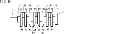
図1A~図1Fは、従来の一般的な鍛造クランク軸の製造工程を説明するための模式図である。図1Fに例示するクランク軸1は、4気筒エンジンに搭載され、4気筒-8枚カウンターウエイトのクランク軸である。そのクランク軸1は、5つのジャーナル部J1~J5、4つのピン部P1~P4、フロント部Fr、フランジ部Fl、および、8枚のクランクアーム部(以下、単に「アーム部」ともいう)A1~A8から構成される。アーム部A1~A8はそれぞれ、ジャーナル部J1~J5とピン部P1~P4をつなぐ。また、8枚の全部のアーム部A1~A8は、カウンターウエイト部(以下、単に「ウエイト部」ともいう)W1~W8を一体で有する。
FIG. 1A to FIG. 1F are schematic views for explaining a manufacturing process of a conventional general forged crankshaft. A crankshaft 1 illustrated in FIG. 1F is mounted on a 4-cylinder engine and is a 4-cylinder-8-counterweight crankshaft. The crankshaft 1 includes five journal portions J1 to J5, four pin portions P1 to P4, a front portion Fr, a flange portion Fl, and eight crank arm portions (hereinafter also simply referred to as “arm portions”) A1. To A8. The arm portions A1 to A8 connect the journal portions J1 to J5 and the pin portions P1 to P4, respectively. Further, all the eight arm portions A1 to A8 integrally have counterweight portions (hereinafter also simply referred to as “weight portions”) W1 to W8.
以下では、ジャーナル部J1~J5、ピン部P1~P4、アーム部A1~A8およびウエイト部W1~W8のそれぞれを総称するとき、その符号は、ジャーナル部で「J」、ピン部で「P」、アーム部で「A」、ウエイト部で「W」とも記す。
Hereinafter, when the journal portions J1 to J5, the pin portions P1 to P4, the arm portions A1 to A8, and the weight portions W1 to W8 are collectively referred to, the reference numerals are “J” for the journal portion and “P” for the pin portion. Also, “A” for the arm portion and “W” for the weight portion.
図1A~図1Fに示す製造方法では、以下のようにして鍛造クランク軸1が製造される。先ず、図1Aに示すような所定の長さのビレット2を加熱炉(例えば誘導加熱炉またはガス雰囲気加熱炉)によって加熱した後、ロール成形を行う。ロール成形工程では、例えば孔型ロールを用いてビレット2を圧延して絞ることにより、ビレット2の体積を長手方向に配分する。これにより、中間素材であるロール荒地3を得る(図1B参照)。次に、曲げ打ち工程では、ロール荒地3を長手方向と垂直な方向から部分的に圧下する。これにより、ロール荒地3の体積を配分し、更なる中間素材である曲げ荒地4を得る(図1C参照)。
In the manufacturing method shown in FIGS. 1A to 1F, the forged crankshaft 1 is manufactured as follows. First, a billet 2 having a predetermined length as shown in FIG. 1A is heated by a heating furnace (for example, an induction heating furnace or a gas atmosphere heating furnace), and then roll forming is performed. In the roll forming step, for example, the volume of the billet 2 is distributed in the longitudinal direction by rolling and squeezing the billet 2 using a perforated roll. Thereby, the roll wasteland 3 which is an intermediate material is obtained (refer FIG. 1B). Next, in the bending step, the roll wasteland 3 is partially crushed from the direction perpendicular to the longitudinal direction. Thereby, the volume of the roll wasteland 3 is distributed and the bending wasteland 4 which is the further intermediate material is obtained (refer FIG. 1C).
続いて、荒打ち工程では、曲げ荒地4を上下に一対の金型を用いて鍛造することにより、荒鍛造材5を得る(図1D参照)。その荒鍛造材5は、クランク軸(最終製品)のおおよその形状を有する。さらに、仕上げ打ち工程では、荒鍛造材5を上下に一対の金型を用いて鍛造することにより、仕上げ鍛造材6を得る(図1E参照)。その仕上げ鍛造材6は、最終製品のクランク軸と合致する形状を有する。これら荒打ちおよび仕上げ打ちのとき、余材が、互いに対向する金型の型割面の間から流出してバリとなる。このため、荒鍛造材5および仕上げ鍛造材6では、いずれも、バリBがクランク軸の形状の周囲に大きく付いている。
Subsequently, in the roughing process, a rough forged material 5 is obtained by forging the bent rough ground 4 up and down using a pair of molds (see FIG. 1D). The rough forged material 5 has an approximate shape of a crankshaft (final product). Further, in the finish punching process, the rough forging material 5 is forged using a pair of upper and lower molds to obtain the finished forging material 6 (see FIG. 1E). The finished forged material 6 has a shape that matches the crankshaft of the final product. At the time of roughing and finishing, surplus material flows out from between the mold splitting surfaces of the molds facing each other to form burrs. For this reason, in both the rough forged material 5 and the finished forged material 6, the burr B is largely attached around the shape of the crankshaft.
バリ抜き工程では、バリ付きの仕上げ鍛造材6を一対の保持型によって挟んで保持した状態で、刃物型によってバリBを打ち抜く。これにより、仕上げ鍛造材6からバリBが除去され、バリ無し鍛造材が得られる。そのバリ無し鍛造材は、図1Fに示す鍛造クランク軸1とほぼ同じ形状を有する。
In the deburring process, the burrs B are punched out with the blade mold while the finished forged material 6 with burrs is held between the pair of holding molds. Thereby, the burr | flash B is removed from the finish forging material 6, and a burr-free forging material is obtained. The forged material without burrs has substantially the same shape as the forged crankshaft 1 shown in FIG. 1F.
整形工程では、バリ無し鍛造材の要所を上下から金型で僅かに圧下し、バリ無し鍛造材を最終製品の寸法形状に矯正する。ここで、バリ無し鍛造材の要所は、例えば、ジャーナル部J、ピン部P、フロント部Fr、フランジ部Flなどといった軸部、さらにはアーム部Aおよびウエイト部Wである。こうして、鍛造クランク軸1が製造される。
In the shaping process, the key points of the burr-free forging material are slightly lowered from above and below with a mold, and the burr-free forging material is corrected to the dimensional shape of the final product. Here, the key points of the burr-free forging material are, for example, the shaft portion such as the journal portion J, the pin portion P, the front portion Fr, the flange portion Fl, the arm portion A, and the weight portion W. Thus, the forged crankshaft 1 is manufactured.
図1A~図1Fに示す製造工程は、図1Fに示す4気筒-8枚カウンターウエイトのクランク軸に限らず、様々なクランク軸に適用できる。例えば、4気筒-4枚カウンターウエイトのクランク軸にも適用できる。
The manufacturing process shown in FIGS. 1A to 1F can be applied to various crankshafts as well as the 4-cylinder-8-piece counterweight crankshaft shown in FIG. 1F. For example, the present invention can be applied to a crankshaft of a 4-cylinder-four-counterweight.
4気筒-4枚カウンターウエイトのクランク軸の場合、8枚のアーム部Aのうちの一部のアーム部が、ウエイト部Wを一体で有する。例えば先頭の第1アーム部A1、最後尾の第8アーム部A8および中央の2枚のアーム部(第4アーム部A4、第5アーム部A5)がウエイト部Wを一体で有する。また、残りのアーム部、具体的には、第2、第3、第6および第7のアーム部A2、A3、A6およびA7は、ウエイト部を有さない。以下では、ウエイト部を有さないアーム部を、「ウエイト無しアーム部」ともいう。ウエイト無しアーム部の形状は、小判状(長円状)となる。
In the case of a 4-cylinder-four-counterweight crankshaft, some of the eight arm portions A have a weight portion W integrally therewith. For example, the first arm portion A1 at the top, the eighth arm portion A8 at the tail and the two central arm portions (fourth arm portion A4 and fifth arm portion A5) have the weight portion W integrally. The remaining arm portions, specifically, the second, third, sixth and seventh arm portions A2, A3, A6 and A7 do not have weight portions. Hereinafter, an arm portion that does not have a weight portion is also referred to as an “unweighted arm portion”. The shape of the arm portion without weight is an oval shape (oval shape).
その他に、3気筒エンジン、直列6気筒エンジン、V型6気筒エンジンおよび8気筒エンジン等に搭載されるクランク軸であっても、製造工程は同様である。なお、ピン部の配置角度の調整が必要な場合は、バリ抜き工程の後に、捩り工程が追加される。
In addition, the manufacturing process is the same for crankshafts mounted on 3-cylinder engines, in-line 6-cylinder engines, V-type 6-cylinder engines, 8-cylinder engines, and the like. In addition, when adjustment of the arrangement angle of a pin part is required, a twist process is added after a deburring process.
近年、特に自動車用のレシプロエンジンには、燃費の向上のために軽量化が求められている。このため、レシプロエンジンに搭載されるクランク軸にも、軽量化の要求が著しくなっている。鍛造クランク軸の軽量化を図る従来技術は、特開2012-7726号公報(特許文献1)および特開2010-230027号公報(特許文献2)に開示される。
In recent years, reciprocating engines for automobiles in particular have been required to be lighter in order to improve fuel efficiency. For this reason, the demand for weight reduction is also increasing in the crankshaft mounted on the reciprocating engine. Conventional techniques for reducing the weight of the forged crankshaft are disclosed in Japanese Patent Application Laid-Open No. 2012-7726 (Patent Document 1) and Japanese Patent Application Laid-Open No. 2010-230027 (Patent Document 2).
特許文献1および2には、ジャーナル部側の表面に穴部が成形されたアーム部が記載され、このアーム部を備えるクランク軸の製造方法も記載される。アーム部の穴部は、ジャーナル部の軸心とピン部の軸心とを結ぶ直線(以下、「アーム部中心線」ともいう)上に成形され、ピン部に向けて大きく深く窪む。このようなアーム部は、穴部の体積分が軽量化される。アーム部の軽量化は、アーム部と対をなすウエイト部の質量軽減につながり、ひいては鍛造クランク軸全体の軽量化につながる。また、穴部が成形されたアーム部は、アーム部中心線を間に挟むピン部近傍の両側部で厚みが厚く維持されていることから、剛性(ねじり剛性および曲げ剛性)も確保される。
Patent Documents 1 and 2 describe an arm part in which a hole part is formed on the surface on the journal part side, and a method of manufacturing a crankshaft including this arm part is also described. The hole part of the arm part is formed on a straight line connecting the axis center of the journal part and the axis part of the pin part (hereinafter also referred to as “arm part center line”), and is deeply recessed toward the pin part. In such an arm portion, the volume of the hole portion is reduced in weight. The weight reduction of the arm portion leads to a reduction in the weight of the weight portion paired with the arm portion, and consequently to the weight reduction of the entire forged crankshaft. Further, since the arm portion in which the hole portion is formed is maintained thick at both side portions in the vicinity of the pin portion sandwiching the arm portion center line therebetween, rigidity (torsional rigidity and bending rigidity) is also ensured.
このように、アーム部の両側部の厚みを厚く維持しつつ、アーム部のジャーナル部側の表面に凹みを持たせれば、軽量化と剛性確保を同時に図ることができる。
Thus, if the surface of the arm portion on the journal portion side is provided with a dent while maintaining the thickness of both side portions of the arm portion, it is possible to reduce the weight and ensure the rigidity at the same time.
ただし、そのような独特な形状のアーム部を備える鍛造クランク軸を従来の製造方法によって製造することは、困難である。型鍛造工程において、アーム部表面に凹みを成形しようとすれば、その凹み部位の金型の型抜き勾配が逆勾配になるからである。この場合、成形された鍛造材が金型から抜けなくなる事態が生じる。
However, it is difficult to manufacture a forged crankshaft having such a uniquely shaped arm portion by a conventional manufacturing method. This is because, in the die forging process, if a dent is to be formed on the surface of the arm portion, the die cutting gradient of the mold at the dent portion becomes a reverse gradient. In this case, a situation occurs in which the molded forged material cannot be removed from the mold.
そのような事態に対処するため、特許文献1および2に記載された製造方法では、型鍛造工程において、アーム部表面に凹みを成形することなくアーム部を小さく成形する。また、バリ抜き工程の後に、アーム部の表面にパンチを押し込み、そのパンチの痕跡によって凹みを成形する。
In order to cope with such a situation, in the manufacturing methods described in Patent Documents 1 and 2, in the die forging step, the arm portion is formed small without forming a recess on the surface of the arm portion. Further, after the deburring step, a punch is pushed into the surface of the arm portion, and a dent is formed by the trace of the punch.
なお、図1Fに示すクランク軸では、アーム部Aおよびそれと一体のウエイト部Wの形状が、全てのアーム部Aで同じである。実際には、必要に応じ、アーム部Aごとに、アーム部Aおよびそれと一体のウエイト部Wの形状を異ならせる場合がある。この技術は、特開2007-71227号公報(特許文献3)および特開2014-40856号公報(特許文献4)に開示される。
In the crankshaft shown in FIG. 1F, the shape of the arm portion A and the weight portion W integrated therewith is the same for all arm portions A. Actually, the shape of the arm part A and the weight part W integrated therewith may be different for each arm part A as required. This technique is disclosed in Japanese Unexamined Patent Application Publication No. 2007-71227 (Patent Document 3) and Japanese Unexamined Patent Application Publication No. 2014-40856 (Patent Document 4).
特許文献3には、一端にフライホイールが装着される4気筒-8枚カウンターウエイトのクランク軸が記載される。そのクランク軸では、アーム部の厚さおよび重心、並びに、ウエイト部の質量が、全部のアーム部で同じでなく、アーム部ごとに異なる。これにより、アーム部ごとに必要最小限の剛性を確保でき、必要な剛性が低いアーム部で肉厚を薄くでき、その結果、軽量化を達成できるとしている。
Patent Document 3 describes a crankshaft of a 4-cylinder-8-counterweight with a flywheel attached to one end. In the crankshaft, the thickness and the center of gravity of the arm portion and the mass of the weight portion are not the same in all the arm portions, but are different for each arm portion. Thereby, the minimum necessary rigidity can be ensured for each arm part, and the thickness can be reduced by the arm part having a low required rigidity, and as a result, weight reduction can be achieved.
特許文献4には、一端にフライホイールが装着される多気筒エンジン用のクランク軸が記載される。そのクランク軸では、アーム部の曲げ剛性およびねじり剛性がフライホイールに近いほど高い。また、アーム部の曲げ剛性およびねじり剛性がアーム部ごとに異なることが好ましいとしている。これにより、曲げ振動およびねじり振動のいずれも軽減しつつ、軽量化を図ることができるとしている。
Patent Document 4 describes a crankshaft for a multi-cylinder engine in which a flywheel is attached to one end. In the crankshaft, the bending rigidity and torsional rigidity of the arm portion are higher as the distance from the flywheel is closer. In addition, it is preferable that the bending rigidity and torsional rigidity of the arm part differ for each arm part. As a result, the weight can be reduced while reducing both bending vibration and torsional vibration.
このようにアーム部ごとに、アーム部およびそれと一体のウエイト部の形状が異なる場合、その形状に応じ、アーム部内で剛性が必要な部位が変化する。具体的には、アーム部のピン部近傍で剛性を確保することが重要となる場合がある。あるいは、アーム部のジャーナル部近傍で剛性を確保することが重要となる場合もある。
Thus, when the shape of the arm portion and the weight portion integrated therewith is different for each arm portion, the portion requiring rigidity in the arm portion changes depending on the shape. Specifically, it may be important to ensure rigidity near the pin portion of the arm portion. Alternatively, it may be important to ensure rigidity near the journal portion of the arm portion.
以下、本発明の実施形態について説明する。以下の説明では、本発明の実施形態について例を挙げて説明するが、本発明は以下で説明する例に限定されない。
Hereinafter, embodiments of the present invention will be described. In the following description, embodiments of the present invention will be described by way of examples, but the present invention is not limited to the examples described below.
(鍛造クランク軸の製造方法)
本発明の製造方法は、鍛造クランク軸の製造方法である。その鍛造クランク軸は、回転中心となるジャーナル部と、そのジャーナル部に対して偏心したピン部と、ジャーナル部とピン部をつなぐ複数のクランクアーム部と、を備える。鍛造クランク軸の複数のクランクアーム部のうちの全部または一部は、カウンターウエイト部を一体で有する。
(Manufacturing method of forged crankshaft)
The manufacturing method of the present invention is a method for manufacturing a forged crankshaft. The forged crankshaft includes a journal portion serving as a rotation center, a pin portion eccentric with respect to the journal portion, and a plurality of crank arm portions connecting the journal portion and the pin portion. All or some of the plurality of crank arm portions of the forged crankshaft integrally have a counterweight portion.
本発明の製造方法は、型鍛造工程とバリ抜き工程とをこの順序で含む。型鍛造工程では、クランク軸の形状が成形されたバリ付きの鍛造材を得る。この鍛造材は、鍛造クランク軸とほぼ同様の形状を有する。この鍛造材は、鍛造クランク軸のジャーナル部、ピン部、複数のクランクアーム部、およびカウンターウエイト部のそれぞれに対応する、粗ジャーナル部、粗ピン部、複数の粗クランクアーム部、および粗カウンターウエイト部を備える。さらに、この鍛造材は、バリおよび後述する余肉部を含む。型鍛造工程に特に限定はなく、図1Dおよび図1Eで説明した荒打ち工程および仕上げ打ち工程を含んでもよい。
The manufacturing method of the present invention includes a die forging step and a deburring step in this order. In the die forging process, a forged material with burrs in which the shape of the crankshaft is formed is obtained. This forged material has substantially the same shape as the forged crankshaft. The forged material includes a rough journal portion, a rough pin portion, a plurality of rough crank arm portions, and a rough counterweight corresponding to each of the journal portion, the pin portion, the plurality of crank arm portions, and the counterweight portion of the forged crankshaft. A part. Further, the forged material includes burrs and a surplus portion to be described later. The die forging process is not particularly limited, and may include the roughing process and the finishing process described with reference to FIGS. 1D and 1E.
バリ抜き工程では、一対の保持型によって鍛造材を挟んだ状態で、鍛造材からバリを除去する。複数の粗クランクアーム部の全部または一部は、粗ピン部近傍の2つの側部の少なくとも一方の外周から突出する第1余肉部を有する。すなわち、複数の粗クランクアーム部の全部または一部は、少なくとも1つの第1余肉部を有する。バリ抜き工程で保持型によって鍛造材を挟む際に、保持型により、第1余肉部を変形させて粗ジャーナル部側に張り出させる。
In the deburring process, burrs are removed from the forging material with the forging material sandwiched between a pair of holding dies. All or some of the plurality of coarse crank arm portions have first surplus portions that protrude from the outer periphery of at least one of the two side portions in the vicinity of the coarse pin portion. That is, all or some of the plurality of coarse crank arm portions have at least one first surplus portion. When the forging material is sandwiched by the holding die in the deburring process, the first surplus portion is deformed by the holding die and protrudes toward the rough journal portion.
複数の粗クランクアーム部の全てが第1余肉部を有してもよい。また、粗カウンターウエイト部を一体で有する粗クランクアーム部の全部または一部が第1余肉部を有してもよい。また、粗カウンターウエイト部を一体で有する粗クランクアーム部のみが第1余肉部を有してもよい。また、粗カウンターウエイト部を有さない粗クランクアーム部の全部または一部が第1余肉部を有してもよい。また、粗カウンターウエイト部を有さない粗クランクアーム部のみが第1余肉部を有してもよい。
All of the plurality of coarse crank arm portions may have the first surplus portion. Further, all or part of the coarse crank arm portion integrally having the coarse counterweight portion may have the first surplus portion. Further, only the coarse crank arm portion integrally having the coarse counterweight portion may have the first surplus portion. Further, all or a part of the rough crank arm portion that does not have the rough counterweight portion may have the first surplus portion. Moreover, only the rough crank arm part which does not have a rough counterweight part may have a 1st surplus part.
前記第1余肉部が、前記粗ピン部近傍の前記2つの側部のそれぞれから突出してもよい。前記粗クランクアーム部は、前記粗ピン部近傍の前記2つの側部の外周から突出する2つの第1余肉部を有してもよい。この構成によれば、ピン部近傍の両側部の剛性を確保できる。2つの第1余肉部の間には、後述する領域As(凹みを有する領域)となる部分が存在する。凹みとなる部分の表面形状は、後述するように、幅方向の中央が膨らむような凸状であってもよい。
The first surplus portion may protrude from each of the two side portions in the vicinity of the rough pin portion. The rough crank arm portion may have two first surplus portions protruding from the outer peripheries of the two side portions near the rough pin portion. According to this configuration, the rigidity of both side portions in the vicinity of the pin portion can be ensured. Between the two first surplus portions, there is a portion that becomes a region As (region having a dent) to be described later. The surface shape of the concave portion may be a convex shape in which the center in the width direction swells as described later.
前記バリ抜き工程において、支持部材が前記バリの下面を支持している状態で、前記保持型により、前記第1余肉部を変形させて前記粗ジャーナル部側に張り出させてもよい。第1余肉部は保持型によって変形されるため、バリ抜き工程の初期段階では、保持型の形状と第1余肉部の形状とは一致していない。そのため、変形前の第1余肉部が存在する鍛造材を保持型の下型のみで支持すると、鍛造材の姿勢が安定しない。この問題は、第1余肉部を粗クランクアーム部の一部のみに形成する場合に特に顕著になる。支持部材を用いることによって、鍛造材の姿勢が安定した状態でバリ抜き工程を行うことができる。具体的には、鍛造材のバリが水平に沿って配置された状態でバリ抜き工程を行うことができる。さらに、支持部材を用いて、上型と下型との間の中央に鍛造材を保持してもよい。
In the deburring step, the first surplus portion may be deformed and protruded toward the rough journal portion by the holding mold while the support member supports the lower surface of the burr. Since the first surplus portion is deformed by the holding mold, the shape of the holding die and the shape of the first surplus portion do not match at the initial stage of the deburring process. Therefore, if the forging material in which the first surplus portion before deformation exists is supported only by the lower mold of the holding die, the posture of the forging material is not stable. This problem is particularly noticeable when the first surplus portion is formed only on a portion of the coarse crank arm portion. By using the support member, the deburring process can be performed in a state where the posture of the forged material is stable. Specifically, the deburring step can be performed in a state in which the burrs of the forging material are arranged along the horizontal. Furthermore, you may hold | maintain a forging material in the center between an upper mold | type and a lower mold | type using a supporting member.
前記支持部材は、前記保持型の動作に伴って、前記バリの下面を支持している状態を維持しながら移動してもよい。保持型の動作に伴ってバリが下方または上方に移動する場合がある。そのような場合には、バリの移動に伴って支持部材が移動(下降または上昇)することが好ましい。
The support member may move while maintaining the state of supporting the lower surface of the burr with the operation of the holding mold. The burr may move downward or upward in accordance with the holding type operation. In such a case, it is preferable that the support member moves (lowers or rises) as the burr moves.
支持部材の端部(バリの下面と当接する端部)は、バリを除去するための刃物型の先端部に対応する形状を有してもよい。例えば、支持部材の端部の輪郭は、最終製品のバリ線に対応する形状を有してもよい。複数の支持部材を用いてバリの下面を支持してもよい。例えば、3つ以上(例えば4つ以上)の支持部材を用いてもよい。4つ以上の支持部材を用いることによって、鍛造材の姿勢を特に安定させることができる。バリの下面の複数箇所を支持する場合、支持部材は、鍛造材のうち質量の偏りが大きい部分(例えばカウンターウエイト部の近傍)を支持することが好ましい。複数の支持部材の高さは、バリ抜き工程開始時の鍛造材の姿勢が安定するように、個々の支持部材ごとに異なっていてもよい。例えば、3気筒用や6気筒用のクランク軸の場合には、鍛造材のバリが同一平面上に形成されない場合がある。この場合は、個々の支持部材の高さを、求められる支持位置に応じた高さとすればよい。
The end portion of the support member (the end portion in contact with the lower surface of the burr) may have a shape corresponding to the front end portion of the blade mold for removing the burr. For example, the contour of the end portion of the support member may have a shape corresponding to the burr line of the final product. A plurality of support members may be used to support the lower surface of the burr. For example, three or more (for example, four or more) support members may be used. By using four or more support members, the posture of the forged material can be particularly stabilized. When supporting a plurality of locations on the lower surface of the burr, it is preferable that the support member supports a portion of the forged material having a large mass deviation (for example, in the vicinity of the counterweight portion). The height of the plurality of support members may be different for each support member so that the posture of the forged material at the start of the deburring process is stabilized. For example, in the case of a crankshaft for 3 cylinders or 6 cylinders, the burrs of the forging material may not be formed on the same plane. In this case, the height of each support member may be set according to the required support position.
支持部材は、上記の所定の動作をするように移動・保持される。支持部材を移動・保持する機構に特に限定はなく、公知の機構を用いてもよい。例えば、油圧シリンダ、モータ、および弾性体(バネ等)などの少なくとも1つを用いて支持部材を移動・保持してもよい。支持部材は、ブランクホルダに用いられる公知の機構で移動・保持してもよい。
The support member is moved and held so as to perform the predetermined operation described above. There is no particular limitation on the mechanism for moving and holding the support member, and a known mechanism may be used. For example, the support member may be moved and held using at least one of a hydraulic cylinder, a motor, and an elastic body (a spring or the like). The support member may be moved and held by a known mechanism used for the blank holder.
前記バリ抜き工程での前記第1余肉部の変形を、押し潰し加工または折り曲げ加工によって行ってもよい。
The deformation of the first surplus portion in the deburring step may be performed by crushing or bending.
前記複数の粗クランクアーム部の全部または一部が、前記粗ジャーナル部近傍の2つの側部の少なくとも一方の外周から突出する第2余肉部を有してもよい。この場合、前記バリ抜き工程で前記保持型によって前記鍛造材を挟む際に、前記保持型により、前記第2余肉部を変形させて前記粗ピン部側に張り出させる。複数の粗クランクアーム部の全てが第2余肉部を有してもよい。また、粗カウンターウエイト部を有する粗クランクアーム部の全部または一部が第2余肉部を有してもよい。また、粗カウンターウエイト部を有する粗クランクアーム部のみが第2余肉部を有してもよい。また、粗カウンターウエイト部を有さない粗クランクアーム部の全部または一部が第2余肉部を有してもよい。また、粗カウンターウエイト部を有さない粗クランクアーム部のみが第2余肉部を有してもよい。
All or a part of the plurality of coarse crank arm portions may have a second surplus portion protruding from the outer periphery of at least one of the two side portions in the vicinity of the coarse journal portion. In this case, when the forging material is sandwiched by the holding die in the deburring step, the second surplus portion is deformed by the holding die and protrudes toward the rough pin portion. All of the plurality of coarse crank arm portions may have the second surplus portion. Further, all or part of the rough crank arm portion having the rough counterweight portion may have the second surplus portion. Further, only the coarse crank arm portion having the coarse counterweight portion may have the second surplus portion. Further, all or a part of the coarse crank arm portion not having the coarse counterweight portion may have the second surplus portion. Moreover, only the rough crank arm part which does not have a rough counterweight part may have a 2nd surplus part.
前記第2余肉部が、前記粗ジャーナル部近傍の前記2つの側部のそれぞれから突出してもよい。前記粗クランクアーム部が、前記粗ジャーナル部近傍の前記2つの側部の外周から突出する2つの第2余肉部を有してもよい。この構成によれば、ジャーナル部近傍の両側部の剛性を確保できる。2つの第2余肉部の間には、後述する領域At(凹みを有する領域)となる部分が存在する。凹みとなる部分の表面形状は、後述するように、幅方向の中央が膨らむような凸状であってもよい。
The second surplus portion may protrude from each of the two side portions in the vicinity of the coarse journal portion. The rough crank arm part may have two second surplus parts protruding from the outer peripheries of the two side parts near the rough journal part. According to this configuration, the rigidity of both side portions in the vicinity of the journal portion can be ensured. Between two 2nd surplus parts, the part used as the area | region At (area | region which has a dent) mentioned later exists. The surface shape of the concave portion may be a convex shape in which the center in the width direction swells as described later.
前記第2余肉部を有する前記粗クランクアーム部が、前記粗カウンターウエイト部を有する前記粗クランクアーム部であってもよい。
The coarse crank arm portion having the second surplus portion may be the coarse crank arm portion having the coarse counterweight portion.
前記第2余肉部を有する前記粗クランクアーム部が、前記粗カウンターウエイト部を有さない前記粗クランクアーム部であってもよい。
The coarse crank arm portion having the second surplus portion may be the coarse crank arm portion not having the coarse counterweight portion.
前記バリ抜き工程での前記第2余肉部の変形を、押し潰し加工または折り曲げ加工によって行ってもよい。
The deformation of the second surplus portion in the deburring step may be performed by crushing or bending.
1つの観点では、本発明は、鍛造クランク軸の製造方法の一例を提供する。この一例の製造方法は、回転中心となるジャーナル部と、そのジャーナル部に対して偏心したピン部と、前記ジャーナル部と前記ピン部をつなぐクランクアーム部と、を備える鍛造クランク軸の製造方法である。前記鍛造クランク軸は、前記クランクアーム部のうちの全部または一部にカウンターウエイト部を一体で有する。この一例の製造方法は、クランクアーム部(粗クランクアーム部)のピン部(粗ピン部)近傍の両側部それぞれの外周に当該外周から突出する第1余肉部を有するクランク軸の形状が成形されたバリ付きの鍛造材を得る型鍛造工程と、一対の保持型によって前記鍛造材を挟み込んだ状態で、前記鍛造材からバリを除去するバリ抜き工程と、を含む。この一例では、前記バリ抜き工程で前記保持型によって前記鍛造材を挟み込む際に、前記第1余肉部を前記保持型によって変形させ、前記クランクアーム部(粗クランクアーム部)の前記ピン部(粗ピン部)近傍の両側部の厚みを増加させる。
In one aspect, the present invention provides an example of a method for manufacturing a forged crankshaft. The manufacturing method of this example is a manufacturing method of a forged crankshaft comprising a journal portion serving as a rotation center, a pin portion eccentric to the journal portion, and a crank arm portion connecting the journal portion and the pin portion. is there. The forged crankshaft has a counterweight portion integrally with all or a part of the crank arm portion. In the manufacturing method of this example, the shape of the crankshaft having the first surplus portion protruding from the outer periphery is formed on the outer periphery of each side portion in the vicinity of the pin portion (coarse pin portion) of the crank arm portion (rough crank arm portion). A die forging step for obtaining the forged material with burrs, and a deburring step for removing the burrs from the forging material with the forging material sandwiched between a pair of holding dies. In this example, when the forging material is sandwiched by the holding die in the deburring step, the first surplus portion is deformed by the holding die, and the pin portion (the coarse crank arm portion) Increase the thickness of both sides in the vicinity of the rough pin portion.
上記の説明では、鍛造材が第1余肉部を必ず含む場合について説明した。しかし、鍛造材が第1余肉部を含まず第2余肉部のみを含む場合でも、本発明の製造方法を適用できる。この場合、上述したように、バリ抜き工程において保持型によって鍛造材を挟む際に、保持型によって第2余肉部を変形させて粗ピン部側に張り出させる。
In the above description, the case where the forged material necessarily includes the first surplus portion has been described. However, the manufacturing method of the present invention can be applied even when the forged material does not include the first surplus portion and includes only the second surplus portion. In this case, as described above, when the forging material is sandwiched by the holding die in the deburring process, the second surplus portion is deformed by the holding die and protrudes to the rough pin portion side.
以下に、本実施形態の鍛造クランク軸の製造方法について、図面を参照しながら説明する。以下の説明では、図1A~図1Fに関して説明した事項については、重複する説明を省略する場合がある。
Hereinafter, a method for manufacturing the forged crankshaft of this embodiment will be described with reference to the drawings. In the following description, a duplicate description of the matters described with reference to FIGS. 1A to 1F may be omitted.
1.クランク軸の形状
本実施形態が対象とする鍛造クランク軸は、回転中心となるジャーナル部と、そのジャーナル部に対して偏心したピン部と、ジャーナル部とピン部をつなぐアーム部と、を備える。アーム部のうちの全部または一部は、ウエイト部を一体で有する。
1. Shape of Crankshaft A forged crankshaft targeted by the present embodiment includes a journal portion serving as a rotation center, a pin portion eccentric to the journal portion, and an arm portion connecting the journal portion and the pin portion. All or some of the arm portions integrally have a weight portion.
1つの観点では、本実施形態で製造される鍛造クランク軸の一例は、エンジンの気筒数に対応する数のユニット(「スロー」とも称される)を含む。1つのユニットは、1つのピン部と、ピン部を挟むように配置された2つのアーム部とを含む。1つのユニットの両端には、2つのジャーナル部が配置される。隣接する2つのユニットは、ジャーナル部によって接続されている。V型6気筒の場合は、2つのピン部の間にアーム部が1つある構造を1つの小ユニットとし、この小ユニットを挟むように2つのアーム部が配置されて大ユニットとなる。さらに、この大ユニットを挟むようにジャーナル部が配置される。
In one aspect, an example of the forged crankshaft manufactured in the present embodiment includes a number of units (also referred to as “throw”) corresponding to the number of cylinders of the engine. One unit includes one pin portion and two arm portions arranged so as to sandwich the pin portion. Two journal parts are arranged at both ends of one unit. Two adjacent units are connected by a journal part. In the case of the V type 6 cylinder, a structure having one arm portion between two pin portions is defined as one small unit, and the two arm portions are arranged so as to sandwich the small unit to be a large unit. Further, a journal portion is arranged so as to sandwich this large unit.
本実施形態の鍛造クランク軸の製造方法は、例えば、4気筒-8枚カウンターウエイトのクランク軸および4気筒-4枚カウンターウエイトのクランク軸に適用できる。その他に、3気筒エンジン、直列6気筒エンジン、V型6気筒エンジンおよび8気筒エンジン等に搭載されるクランク軸にも適用できる。
The method for manufacturing a forged crankshaft according to the present embodiment can be applied to, for example, a crankshaft of a 4-cylinder-8-counter weight and a crankshaft of a 4-cylinder-four-counterweight. In addition, the present invention can be applied to a crankshaft mounted on a 3-cylinder engine, an in-line 6-cylinder engine, a V-type 6-cylinder engine, an 8-cylinder engine, or the like.
より具体的には、本実施形態の鍛造クランク軸の製造方法は、図2A~図2Dに示す第1構成例の鍛造クランク軸、図4A~図4Dに示す第2構成例の鍛造クランク軸、および、図6Aおよび図6Bに示す第3構成例の鍛造クランク軸に適用できる。
More specifically, the manufacturing method of the forged crankshaft of the present embodiment includes the forged crankshaft of the first configuration example shown in FIGS. 2A to 2D, the forged crankshaft of the second configuration example shown in FIGS. 4A to 4D, And it is applicable to the forged crankshaft of the 3rd structural example shown to FIG. 6A and FIG. 6B.
第1~第3構成例の鍛造クランク軸では、いずれも、ウエイト部の有無に依拠することなく、全部のアーム部のジャーナル部側の表面に凹みが設けられる。なお、後述するように、一部のアーム部のジャーナル部側の表面に、凹みを設けてもよい。第2構成例では、さらに、ウエイト部を一体で有するアーム部のピン部側の表面に凹みが設けられる。第3構成例は、ウエイト無しアーム部を有する。その第3構成例では、上述のジャーナル部側の表面に凹みに加え、ウエイト無しアーム部のピン部側の表面に凹みが設けられる。
In the forged crankshafts of the first to third configuration examples, all the arm portions are provided with dents on the journal portion side surface without depending on the presence or absence of the weight portion. As will be described later, a recess may be provided on the surface of the journal portion side of some arm portions. In the second configuration example, a recess is further provided on the surface of the arm portion integrally including the weight portion on the pin portion side. The third configuration example has a weightless arm portion. In the third configuration example, in addition to the dent on the surface on the journal part side described above, a dent is provided on the surface on the pin part side of the arm part without weight.
本実施形態のクランク軸の製造方法は、アーム部に凹みを設けるため、バリ付きの鍛造材を得る型鍛造工程と、その鍛造材からバリを除去するバリ抜き工程とを含む。また、鍛造材の粗アーム部は、第1余肉部を有し、バリ抜き工程では、その第1余肉部を変形させて粗ジャーナル部側に張り出させる。以下に、鍛造クランク軸(最終製品)および鍛造材におけるアーム部の形状をそれぞれ説明する。
The crankshaft manufacturing method of the present embodiment includes a die forging step for obtaining a forged material with burrs and a deburring step for removing burrs from the forged material in order to provide a recess in the arm portion. Further, the rough arm portion of the forged material has a first surplus portion, and in the deburring process, the first surplus portion is deformed and protrudes toward the rough journal portion. Below, the shape of the arm part in a forge crankshaft (final product) and a forging material is each demonstrated.
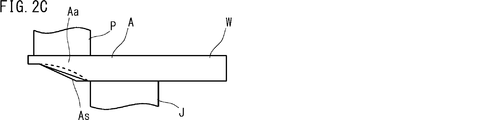
図2A~図2Dは、本発明の第1構成例のクランク軸におけるバリ抜き後のアーム部を示す模式図である。図2Aは斜視図、図2Bはジャーナル部側表面を示す図、図2Cは側面を示す図である。図2Dは、図2Bの線IID-IIDにおける断面図である。図2A~図2Dには、クランク軸のアーム部(ウエイト部を含む)の1つを抽出して示す。なお、図2Cは、図2Bの破線矢印で示す方向から見た図である。
FIGS. 2A to 2D are schematic views showing an arm portion after deburring in the crankshaft of the first configuration example of the present invention. FIG. 2A is a perspective view, FIG. 2B is a view showing a journal side surface, and FIG. 2C is a side view. 2D is a cross-sectional view taken along line IID-IID in FIG. 2B. 2A to 2D, one of the arm portions (including the weight portion) of the crankshaft is extracted and shown. 2C is a view as seen from the direction indicated by the broken-line arrow in FIG. 2B.
第1構成例のアーム部Aは、図2A~図2Dに示すように、ジャーナル部J側の表面のうち、ピン部P近傍の両側部(2つの側部)AaおよびAbの内側の領域Asに凹みを有する。また、ピン部P近傍の両側部AaおよびAbがジャーナル部J側に張り出し、それらの両側部AaおよびAbの厚みは、凹みの厚みと比べ、厚肉である。ここで、側部とは、アーム部Aの幅方向(ピン部の偏心方向と垂直な方向)の側面およびその周辺部分を意味し、換言すると、アーム部Aの幅方向の端部を意味する。領域Asは、アーム部Aの表面のうち、ピン部Pとは反対側の表面に位置する。
As shown in FIGS. 2A to 2D, the arm portion A of the first configuration example includes a region As on the inside of the both side portions (two side portions) Aa and Ab in the vicinity of the pin portion P on the surface on the journal portion J side. Has a dent. Further, both side portions Aa and Ab in the vicinity of the pin portion P project to the journal portion J side, and the thicknesses of the both side portions Aa and Ab are thicker than the thickness of the recess. Here, the side portion means the side surface in the width direction of the arm portion A (direction perpendicular to the eccentric direction of the pin portion) and its peripheral portion, in other words, the end portion in the width direction of the arm portion A. . The region As is located on the surface of the arm portion A opposite to the pin portion P.
このような第1構成例のアーム部Aでは、ピン部P近傍の両側部AaおよびAbの厚みが、凹みを有さないアーム部のように厚く維持される。また、そのアーム部Aには、結果的にジャーナル部J側の表面に凹みが設けられる。このため、第1構成例の鍛造クランク軸は、アーム部Aの凹みによって軽量化を図ることができる。加えて、アーム部Aの両側部AaおよびAbの厚み維持によって剛性の確保を図ることができる。換言すると、アーム部Aのピン部P近傍の両側部AaおよびAbの厚みが、凹みの厚みと比べ、厚肉であることにより、剛性の確保を図ることができる。
In the arm part A of such a first configuration example, the thickness of both side parts Aa and Ab in the vicinity of the pin part P is maintained as thick as the arm part having no recess. Further, as a result, the arm portion A is provided with a dent on the surface on the journal portion J side. For this reason, the forged crankshaft of the first configuration example can be reduced in weight by the recess of the arm portion A. In addition, it is possible to ensure rigidity by maintaining the thickness of both side portions Aa and Ab of the arm portion A. In other words, since the thickness of both side portions Aa and Ab near the pin portion P of the arm portion A is thicker than the thickness of the recess, it is possible to ensure rigidity.
両側部AaおよびAbの内側領域Asの断面形状(凹みの底面形状)は、図2Dに示すように、幅方向の中央が膨らむような凸状であることが好ましい。換言すると、内側領域Asの厚みは、幅方向の中央から遠ざかるに従って漸次減少することが好ましい。凹みの底面形状は幅方向の中央が膨らむような凸状であるため、曲げ剛性をより向上できる。幅方向の中央およびその周辺の断面形状を、例えば、円弧状、半楕円状または放物線状とすれば、上述の断面形状を実現できる。
The cross-sectional shape (indented bottom surface shape) of the inner region As of both side portions Aa and Ab is preferably a convex shape in which the center in the width direction swells as shown in FIG. 2D. In other words, it is preferable that the thickness of the inner region As gradually decreases as the distance from the center in the width direction increases. Since the bottom shape of the dent is a convex shape in which the center in the width direction swells, the bending rigidity can be further improved. If the cross-sectional shape in the center in the width direction and the periphery thereof is, for example, an arc shape, a semi-elliptical shape, or a parabolic shape, the above-described cross-sectional shape can be realized.
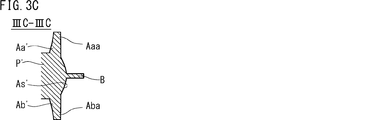
図3A~図3Cは、本発明の第1構成例のクランク軸におけるバリ抜き工程前(バリ付き鍛造材)の粗アーム部を示す模式図である。図3Aは粗ジャーナル部側表面を示す図、図3Bは側面を示す図である。図3Cは、図3Aの線IIIC-IIICにおける断面図である。図3A~図3Cでは、クランク軸の粗アーム部(粗ウエイト部W’を含む)の1つを抽出して示す。なお、図3Bは、図3Aの破線矢印で示す方向から見た図である。
FIGS. 3A to 3C are schematic views showing a rough arm portion before a deburring process (forged material with burrs) in the crankshaft of the first configuration example of the present invention. FIG. 3A is a diagram showing the surface of the rough journal portion side, and FIG. 3B is a diagram showing the side surface. 3C is a cross-sectional view taken along line IIIC-IIIC in FIG. 3A. 3A to 3C, one of the coarse arm portions (including the coarse weight portion W ′) of the crankshaft is extracted and shown. 3B is a view as seen from the direction indicated by the broken-line arrow in FIG. 3A.
バリ抜き工程前の粗アーム部A’は、図3A~図3Cに示すように、粗ジャーナル部J’側の表面のうち、粗ピン部P’近傍の両側部Aa’およびAb’の内側領域As’に、バリ抜き後の凹みの底面形状と合致する表面形状を有する。その表面形状は粗ピン部P’近傍の両側部Aa’およびAb’の領域まで滑らかに広がる。これにより、両側部Aa’およびAb’の厚みは、バリ抜き後の厚みよりも薄い。
As shown in FIGS. 3A to 3C, the rough arm portion A ′ before the deburring process is an inner region of both side portions Aa ′ and Ab ′ in the vicinity of the rough pin portion P ′ on the surface on the rough journal portion J ′ side. As ′ has a surface shape that matches the bottom shape of the dent after deburring. The surface shape smoothly spreads to the regions of both side portions Aa 'and Ab' near the rough pin portion P '. Thereby, the thickness of both side parts Aa 'and Ab' is thinner than the thickness after deburring.
さらに、粗アーム部A’は、粗ピン部P’近傍の両側部Aa’およびAb’のそれぞれの外周に第1余肉部AaaおよびAbaを有する。第1余肉部AaaおよびAbaはそれぞれ、粗ピン部P’近傍の両側部Aa’およびAb’の外周から突出する。この第1余肉部AaaおよびAbaは、板状であり、粗ピン部P’近傍の両側部Aa’およびAb’の外周に沿って設けられる。第1余肉部AaaおよびAbaの厚みは、その根元の両側部Aa’およびAb’の厚みと比べ、同程度であるかまたは薄い。
Further, the coarse arm portion A 'has first surplus portions Aaa and Aba on the outer circumferences of both side portions Aa' and Ab 'in the vicinity of the coarse pin portion P'. The first surplus portions Aaa and Aba protrude from the outer peripheries of both side portions Aa 'and Ab' near the rough pin portion P ', respectively. The first surplus portions Aaa and Aba are plate-like and are provided along the outer peripheries of both side portions Aa 'and Ab' in the vicinity of the rough pin portion P '. The thicknesses of the first surplus portions Aaa and Aba are the same or thinner than the thicknesses of both side portions Aa 'and Ab' at the base.
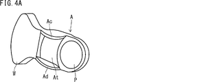
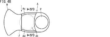
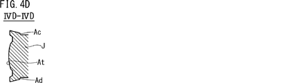
図4A~図4Dは、本発明の第2構成例のクランク軸におけるバリ抜き後のアーム部を示す模式図である。図4Aは斜視図、図4Bはピン部側表面を示す図、図4Cは側面を示す図である。図4Dは、図4Bの線IVD-IVDにおける断面図である。図4A~図4Dには、クランク軸のアーム部(ウエイト部を含む)の1つを抽出して示す。なお、図4Cは、図4Bの破線矢印で示す方向から見た図である。
FIGS. 4A to 4D are schematic views showing an arm portion after deburring in a crankshaft according to a second configuration example of the present invention. 4A is a perspective view, FIG. 4B is a diagram showing a pin portion side surface, and FIG. 4C is a diagram showing a side surface. 4D is a cross-sectional view taken along line IVD-IVD in FIG. 4B. 4A to 4D show one of the crankshaft arm portions (including the weight portion). 4C is a view as seen from the direction indicated by the broken-line arrow in FIG. 4B.
第2構成例のアーム部Aでは、上記の第1構成例と同様に、ピン部P近傍の両側部の厚みが厚くされるとともに、ジャーナル部J側の表面に凹みを有する。加えて、第2構成例のウエイト部を一体で有するアーム部Aは、図4A~図4Dに示すように、ピン部P側の表面のうち、ジャーナル部J近傍の両側部(2つの側部)AcおよびAdの内側の領域Atに、凹みを有する。また、ジャーナル部J近傍の両側部AcおよびAdがピン部P側に張り出し、それらの両側部AcおよびAdの厚みは、凹みの厚みと比べ、厚肉である。領域Atは、アーム部Aの表面のうち、ジャーナル部Jとは反対側の表面に位置する。
In the arm portion A of the second configuration example, the thickness of both side portions near the pin portion P is increased and the surface on the journal portion J side has a dent, as in the first configuration example. In addition, as shown in FIGS. 4A to 4D, the arm portion A integrally including the weight portion of the second configuration example has both side portions (two side portions) in the vicinity of the journal portion J on the surface on the pin portion P side. ) It has a dent in the area | region At inside Ac and Ad. Moreover, both side parts Ac and Ad in the vicinity of the journal part J project to the pin part P side, and the thicknesses of both side parts Ac and Ad are thicker than the thickness of the recess. The region At is located on the surface of the arm portion A on the surface opposite to the journal portion J.
このような第2構成例のアーム部Aは、ピン部P近傍の両側部AaおよびAbの厚みが厚くされるとともに、ジャーナル部J側の表面に凹みが設けられる。ウエイト部を一体で有するアーム部Aは、さらに、ジャーナル部J近傍の両側部AcおよびAdの厚みが、凹みを有さないアーム部のように、厚く維持される。また、ウエイト部を一体で有するアーム部Aには、結果的にピン部P側の表面に凹みが設けられる。
In the arm portion A of the second configuration example as described above, the thickness of both side portions Aa and Ab near the pin portion P is increased, and a recess is provided on the surface on the journal portion J side. In the arm part A having the weight part integrally, the thicknesses of the both side parts Ac and Ad in the vicinity of the journal part J are kept thick like the arm part having no recess. Further, as a result, the arm part A integrally having the weight part is provided with a dent on the surface on the pin part P side.
このため、第2構成例による鍛造クランク軸は、アーム部Aのジャーナル部J側およびピン部P側の凹みによって軽量化をさらに図ることができる。加えて、ピン部P近傍の両側部AaおよびAb並びにジャーナル部J近傍の両側部AcおよびAdの厚みが維持されることにより、剛性の確保を図ることができる。換言すると、ピン部P近傍の両側部AaおよびAb並びにジャーナル部J近傍の両側部AcおよびAdの厚みが、凹みの厚みと比べ、厚肉であることにより、剛性の確保を図ることができる。
For this reason, the forged crankshaft according to the second configuration example can be further reduced in weight by the depressions on the journal portion J side and the pin portion P side of the arm portion A. In addition, by maintaining the thicknesses of the side portions Aa and Ab near the pin portion P and the side portions Ac and Ad near the journal portion J, it is possible to ensure rigidity. In other words, the thicknesses of the side portions Aa and Ab near the pin portion P and the side portions Ac and Ad near the journal portion J are thicker than the thickness of the recess, thereby ensuring rigidity.
ウエイト部を一体で有するアーム部Aでは、両側部AcおよびAdの内側領域Atの断面形状(凹みの底面形状)が、図4Dに示すように、幅方向の中央が膨らむような凸状であることが好ましい。換言すると、内側領域Atの厚みは、幅方向の中央から遠ざかるに従って漸次減少することが好ましい。凹みの底面形状は幅方向の中央が膨らむような凸状であるため、曲げ剛性をより向上できる。幅方向の中央およびその周辺の断面形状を、例えば、円弧状、半楕円状または放物線状とすれば、上述の断面形状を実現できる。
In the arm part A integrally having the weight part, the cross-sectional shape (bottom shape of the dent) of the inner region At of both side parts Ac and Ad is a convex shape in which the center in the width direction swells as shown in FIG. 4D. It is preferable. In other words, it is preferable that the thickness of the inner region At gradually decreases as the distance from the center in the width direction increases. Since the bottom shape of the dent is a convex shape in which the center in the width direction swells, the bending rigidity can be further improved. If the cross-sectional shape in the center in the width direction and the periphery thereof is, for example, an arc shape, a semi-elliptical shape, or a parabolic shape, the above-described cross-sectional shape can be realized.
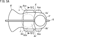
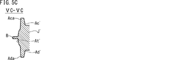
図5A~図5Cは、本発明の第2構成例のクランク軸におけるバリ抜き工程前(バリ付き鍛造材)の粗アーム部を示す模式図である。図5Aは粗ピン部側表面を示す図、図5Bは側面を示す図である。図5Cは、図5Aの線VC-VCにおける断面図である。図5A~図5Cでは、クランク軸の粗アーム部(粗ウエイト部を含む)の1つを抽出して示す。なお、図5Bは、図5Aの破線矢印で示す方向から見た図である。
FIGS. 5A to 5C are schematic views showing a rough arm portion of the crankshaft of the second configuration example of the present invention before the deburring step (forged material with burrs). FIG. 5A is a diagram showing a surface on the rough pin portion side, and FIG. 5B is a diagram showing a side surface. FIG. 5C is a cross-sectional view taken along line VC-VC in FIG. 5A. 5A to 5C, one of the coarse arm portions (including the coarse weight portion) of the crankshaft is extracted and shown. 5B is a view as seen from the direction indicated by the broken-line arrow in FIG. 5A.
第2構成例では、バリ抜き工程前の粗アーム部A’が、上記の第1構成例と同様に、粗ジャーナル部J’側の表面のうち、粗ピン部P’近傍の両側部Aa’およびAb’の内側領域As’に、バリ抜き後の凹みの底面形状と合致する表面形状を持つ。また、その粗アーム部A’は、上記の第1構成例と同様に、粗ピン部P’近傍の両側部Aa’およびAb’のそれぞれの外周から突出する第1余肉部AaaおよびAbaを有する。
In the second configuration example, the rough arm portion A ′ before the deburring process is similar to the first configuration example, in the surface on the rough journal portion J ′ side, both side portions Aa ′ in the vicinity of the rough pin portion P ′. And the inner region As ′ of Ab ′ has a surface shape that matches the bottom shape of the dent after deburring. In addition, the coarse arm portion A ′ includes first surplus portions Aaa and Aba protruding from the outer circumferences of both side portions Aa ′ and Ab ′ in the vicinity of the coarse pin portion P ′, as in the first configuration example. Have.
加えて、ウエイト部を一体で有する粗アーム部A’は、粗ピン部P’側の表面のうち、粗ジャーナル部J’近傍の両側部Ac’およびAd’の内側領域At’に、バリ抜き後の凹みの底面形状と合致する表面形状を持つ。その表面形状は粗ジャーナル部J’近傍の両側部Ac’およびAd’の領域まで滑らかに広がる。これにより、粗ジャーナル部J’近傍の両側部Ac’およびAd’の厚みは、バリ抜き後の厚みよりも薄い。
In addition, the rough arm portion A ′ integrally having the weight portion is deburred to the inner region At ′ of both side portions Ac ′ and Ad ′ in the vicinity of the rough journal portion J ′ on the surface on the rough pin portion P ′ side. It has a surface shape that matches the bottom shape of the back dent. The surface shape smoothly spreads to the regions of both side portions Ac ′ and Ad ′ in the vicinity of the rough journal portion J ′. Thereby, the thicknesses of both side portions Ac ′ and Ad ′ in the vicinity of the rough journal portion J ′ are thinner than the thickness after deburring.
また、ウエイト部を一体で有する粗アーム部A’は、粗ジャーナル部J’近傍の両側部Ac’およびAd’のそれぞれの外周に第2余肉部AcaおよびAdaを有する。その第2余肉部AcaおよびAdaはそれぞれ、粗ジャーナル部J’近傍の両側部Ac’およびAd’の外周から突出する。図5A~図5Cに示す第2余肉部AcaおよびAdaは、板状であり、粗ジャーナル部J’近傍の両側部Ac’およびAd’の外周に沿って設けられる。第2余肉部AcaおよびAdaの厚みは、その根元の両側部Ac’およびAd’の厚みと比べ、同程度であるかまたは薄い。
Further, the coarse arm portion A ′ integrally including the weight portion has second surplus portions Aca and Ada on the outer circumferences of both side portions Ac ′ and Ad ′ in the vicinity of the coarse journal portion J ′. The second surplus portions Aca and Ada protrude from the outer peripheries of both side portions Ac 'and Ad' near the coarse journal portion J ', respectively. The second surplus portions Aca and Ada shown in FIGS. 5A to 5C are plate-shaped, and are provided along the outer peripheries of both side portions Ac ′ and Ad ′ in the vicinity of the coarse journal portion J ′. The thicknesses of the second surplus portions Aca and Ada are comparable to or thinner than the thicknesses of the both side portions Ac ′ and Ad ′ at the base.
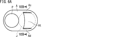
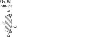
図6Aおよび図6Bは、本発明の第3構成例のクランク軸におけるバリ抜き後のアーム部を示す模式図である。図6Aはピン部側表面を示す図である。図6Bは、図6Aの線VIB-VIBにおける断面図である。第3構成例のクランク軸は、複数のアーム部を有し、そのうちの一部のアーム部がウエイト部を一体で有する。図6Aおよび図6Bには、ウエイト部を有さないアーム部、すなわち、ウエイト無しアーム部の1つを抽出して示す。
FIG. 6A and FIG. 6B are schematic views showing the arm part after deburring in the crankshaft of the third configuration example of the present invention. FIG. 6A is a diagram illustrating a surface of the pin portion side. 6B is a cross-sectional view taken along line VIB-VIB in FIG. 6A. The crankshaft of the third configuration example has a plurality of arm portions, and some of the arm portions integrally have a weight portion. FIG. 6A and FIG. 6B show one of the arm portions having no weight portion, that is, one of the arm portions without weight.
第3構成例のアーム部Aでは、図示を省略するが、ウエイト部の有無に依拠することなく、上記の第1構成例と同様に、ピン部P近傍の両側部の厚みが厚くされるとともに、ジャーナル部J側の表面に凹みを有する。加えて、第3構成例のウエイト無しアーム部Aは、図6Aおよび図6Bに示すように、ピン部P側の表面のうち、ジャーナル部J近傍の両側部AcおよびAdの内側の領域Atに、凹みを有する。また、ジャーナル部J近傍の両側部AcおよびAdがピン部P側に張り出し、それらの両側部AcおよびAdの厚みは、凹みの厚みと比べ、厚肉である。
In the arm portion A of the third configuration example, although not shown, the thickness of both side portions in the vicinity of the pin portion P is increased without depending on the presence or absence of the weight portion, as in the first configuration example, The surface of the journal part J side has a dent. In addition, as shown in FIGS. 6A and 6B, the weightless arm portion A of the third configuration example is formed in a region At inside the both side portions Ac and Ad in the vicinity of the journal portion J on the surface on the pin portion P side. , With a dent. Moreover, both side parts Ac and Ad in the vicinity of the journal part J project to the pin part P side, and the thicknesses of both side parts Ac and Ad are thicker than the thickness of the recess.
このような第3構成例のアーム部Aでは、ピン部P近傍の両側部AaおよびAbの厚みが厚く維持されるとともに、ジャーナル部J側の表面に凹みが設けられる。ウエイト無しアーム部Aでは、さらに、ジャーナル部J近傍の両側部AcおよびAdの厚みが、凹みを有さないアーム部のように厚く維持される。また、ウエイト無しアーム部Aには、結果的にピン部P側の表面に凹みが設けられる。
In the arm portion A of the third configuration example as described above, the thickness of both side portions Aa and Ab near the pin portion P is maintained thick, and a recess is provided on the surface on the journal portion J side. In the arm portion A with no weight, the thicknesses of both side portions Ac and Ad in the vicinity of the journal portion J are maintained as thick as the arm portion having no recess. Further, as a result, the arm portion A having no weight is provided with a dent on the surface on the pin portion P side.
このため、第3構成例による鍛造クランク軸は、アーム部Aのジャーナル部J側およびピン部P側の凹みによって軽量化をさらに図ることができる。加えて、ピン部P近傍の両側部AaおよびAb並びにジャーナル部J近傍の両側部AcおよびAdの厚みが維持されることにより、剛性の確保を図ることができる。換言すると、ピン部P近傍の両側部AaおよびAb並びにジャーナル部J近傍の両側部AcおよびAdの厚みが、凹みの厚みと比べ、厚肉であることにより、剛性の確保を図ることができる。
For this reason, the forged crankshaft according to the third configuration example can be further reduced in weight by the depressions on the journal portion J side and the pin portion P side of the arm portion A. In addition, by maintaining the thicknesses of the side portions Aa and Ab near the pin portion P and the side portions Ac and Ad near the journal portion J, it is possible to ensure rigidity. In other words, the thicknesses of the side portions Aa and Ab near the pin portion P and the side portions Ac and Ad near the journal portion J are thicker than the thickness of the recess, thereby ensuring rigidity.
ウエイト無しアーム部Aでは、両側部AcおよびAdの内側領域Atの形状(凹みの底面形状)が、図6Bに示すように、幅方向の中央が膨らむような凸状であることが好ましい。換言すると、内側領域Atの厚みは、幅方向の中央から遠ざかるに従って漸次減少することが好ましい。凹みの底面形状は幅方向の中央が膨らむような凸状であるため、曲げ剛性をより向上できる。幅方向の中央およびその周辺の断面形状を、例えば、円弧状、半楕円状または放物線状とすれば、上述の断面形状を実現できる。
In the unweighted arm portion A, it is preferable that the shape of the inner region At (the shape of the bottom surface of the recess) of the side portions Ac and Ad is a convex shape in which the center in the width direction swells as shown in FIG. 6B. In other words, it is preferable that the thickness of the inner region At gradually decreases as the distance from the center in the width direction increases. Since the bottom shape of the dent is a convex shape in which the center in the width direction swells, the bending rigidity can be further improved. If the cross-sectional shape in the center in the width direction and the periphery thereof is, for example, an arc shape, a semi-elliptical shape, or a parabolic shape, the above-described cross-sectional shape can be realized.
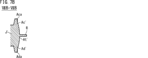
図7Aおよび図7Bは、本発明の第3構成例のクランク軸におけるバリ抜き工程前(バリ付き鍛造材)の粗アーム部を示す模式図である。図7Aは粗ピン部側表面を示す図である。図7Bは、図7Aの線VIIB-VIIBにおける断面図である。図7Aおよび図7Bでは、ウエイト無し粗アーム部の1つを抽出して示す。
FIGS. 7A and 7B are schematic views showing a rough arm portion before a deburring step (forged material with burrs) in the crankshaft of the third configuration example of the present invention. FIG. 7A is a diagram showing a surface on the rough pin portion side. FIG. 7B is a cross-sectional view taken along line VIIB-VIIB in FIG. 7A. In FIG. 7A and FIG. 7B, one of the unweighted rough arm portions is extracted and shown.
バリ抜き工程前の粗アーム部A’は、図示を省略するが、粗ウエイト部の有無に依拠することなく、上記の第1構成例と同様に、粗ジャーナル部J’側の表面のうち、粗ピン部P’近傍の両側部の内側領域に、バリ抜き後の凹みの底面形状と合致する表面形状を持つ。また、粗アーム部A’は、上記の第1構成例と同様に、粗ピン部P’近傍の両側部Aa’およびAb’のそれぞれの外周から突出する第1余肉部AaaおよびAbaを有する。
Although the rough arm portion A ′ before the deburring step is omitted in the drawing, it does not depend on the presence or absence of the rough weight portion, and the surface of the rough journal portion J ′ side, as in the first configuration example, The inner region on both sides near the rough pin portion P ′ has a surface shape that matches the bottom shape of the dent after deburring. The coarse arm portion A ′ has first surplus portions Aaa and Aba protruding from the outer circumferences of both side portions Aa ′ and Ab ′ in the vicinity of the coarse pin portion P ′, as in the first configuration example. .
バリ抜き工程前のウエイト無し粗アーム部A’は、図7Aおよび図7Bに示すように、粗ピン部P’側の表面のうち、粗ジャーナル部J’近傍の両側部Ac’およびAd’の内側領域At’に、バリ抜き後の凹みの底面形状と合致する表面形状を持つ。その表面形状は粗ジャーナル部J’近傍の両側部Ac’およびAd’の領域まで滑らかに広がる。これにより、粗ジャーナル部J’近傍の両側部Ac’およびAd’の厚みは、バリ抜き後の厚みよりも薄い。
As shown in FIGS. 7A and 7B, the coarse arm portion A ′ without weight before the deburring process is formed on the both sides Ac ′ and Ad ′ in the vicinity of the coarse journal portion J ′ on the surface on the coarse pin portion P ′ side. The inner region At ′ has a surface shape that matches the bottom shape of the dent after deburring. The surface shape smoothly spreads to the regions of both side portions Ac ′ and Ad ′ in the vicinity of the rough journal portion J ′. Thereby, the thicknesses of both side portions Ac ′ and Ad ′ in the vicinity of the rough journal portion J ′ are thinner than the thickness after deburring.
また、ウエイト無し粗アーム部A’は、粗ジャーナル部J’近傍の両側部Ac’およびAd’のそれぞれの外周に第2余肉部AcaおよびAdaを有する。第2余肉部AcaおよびAdaはそれぞれ、粗ジャーナル部J’近傍の両側部Ac’およびAd’の外周から突出する。この第2余肉部AcaおよびAdaは、板状であり、粗ジャーナル部J’近傍の両側部Ac’およびAd’の外周に沿って設けられる。第2余肉部AcaおよびAdaの厚みは、その根元の両側部Ac’およびAd’の厚みと比べ、同程度であるかまたは薄い。
Further, the coarse arm portion A ′ without weight has second surplus portions Aca and Ada on the outer circumferences of both side portions Ac ′ and Ad ′ in the vicinity of the coarse journal portion J ′. The second surplus portions Aca and Ada protrude from the outer peripheries of both side portions Ac 'and Ad' near the coarse journal portion J ', respectively. The second surplus portions Aca and Ada are plate-shaped and are provided along the outer peripheries of both side portions Ac 'and Ad' in the vicinity of the coarse journal portion J '. The thicknesses of the second surplus portions Aca and Ada are comparable to or thinner than the thicknesses of the both side portions Ac ′ and Ad ′ at the base.
2.鍛造クランク軸の製造方法
本実施形態の鍛造クランク軸の製造方法は、型鍛造工程と、バリ抜き工程とを含む。型鍛造工程の前工程として、例えば、予備成形工程を設けることができる。また、バリ抜き工程の後工程として、例えば、整形工程を設けることができる。なお、ピン部の配置角度の調整が必要な場合は、バリ抜き工程の後に、捩り工程が追加される。これらの工程は、いずれも、熱間で一連に行われる。本実施形態の鍛造クランク軸の製造方法のうち、本発明の特徴部分を除く部分には、従来の製造方法を適用してもよい。例えば、本発明の特徴部分を除く部分には、図1A~図1Fで説明した工程のうちの少なくとも1つの工程、またはそれを本発明に適合するように修正した工程を適用してもよい。
2. Manufacturing method of forged crankshaft The manufacturing method of the forged crankshaft of this embodiment includes a die forging step and a deburring step. As a pre-process of the die forging process, for example, a preforming process can be provided. Further, for example, a shaping step can be provided as a step after the deburring step. In addition, when adjustment of the arrangement angle of a pin part is required, a twist process is added after a deburring process. All of these steps are performed in a series of heat. Of the manufacturing method of the forged crankshaft of the present embodiment, a conventional manufacturing method may be applied to the portion excluding the characteristic portion of the present invention. For example, at least one of the steps described with reference to FIGS. 1A to 1F or a step modified so as to be compatible with the present invention may be applied to the portions other than the features of the present invention.
予備成形工程は、例えば、ロール成形工程と曲げ打ち工程とで構成できる。ロール成形工程および曲げ打ち工程では、ビレット(原材料)の体積を配分し、曲げ荒地を成形する。
The preforming process can be composed of, for example, a roll forming process and a bending process. In the roll forming process and the bending process, the volume of the billet (raw material) is distributed and the bending waste is formed.
型鍛造工程では、前記図3A~図3Cに示すようなバリ付きの鍛造材を得る。そのバリ付きの鍛造材には、クランク軸の形状が成形され、具体的には、バリ付きの鍛造材は、粗ジャーナル部J’、粗ピン部P’および粗アーム部A’等を有する。また、バリ付きの鍛造材は、粗アーム部A’の粗ピン部P’近傍の側部Aa’およびAb’の外周から突出する第1余肉部AaaおよびAbaを有する。すなわち、型鍛造工程では、余肉部(第1余肉部、第2余肉部、または、第1余肉部および第2余肉部)を形成できる金型を用いて型鍛造を行う。
In the die forging step, a forged material with burrs as shown in FIGS. 3A to 3C is obtained. The forged material with burrs has the shape of the crankshaft. Specifically, the forged material with burrs has a rough journal portion J ', a rough pin portion P', a rough arm portion A ', and the like. The forged material with burrs has first surplus portions Aaa and Aba protruding from the outer periphery of the side portions Aa 'and Ab' in the vicinity of the rough pin portion P 'of the rough arm portion A'. That is, in the die forging step, die forging is performed using a mold capable of forming a surplus portion (first surplus portion, second surplus portion, or first surplus portion and second surplus portion).
このようなバリ付きの鍛造材を得る型鍛造工程は、例えば、荒打ち工程と仕上げ打ち工程とで構成できる。
The die forging process for obtaining such a forged material with burrs can be composed of, for example, a roughing process and a finishing process.
型鍛造工程の型抜き勾配は、逆勾配にならない。具体的には、粗アーム部の粗ジャーナル部J’側表面に設けられる凹みの底面(内側領域As’)に対応する部位、並びに、第1余肉部AaaおよびAbaに対応する部位のいずれでも、型抜き勾配は逆勾配にならない。換言すれば、上記形状を有する鍛造材は、型抜き勾配が逆勾配にならない金型を用いて形成できる。このため、荒打ちと仕上げ打ちのいずれの型鍛造も、支障なく行え、前記図3A~図3Cに示すようなバリ付きの鍛造材を得ることができる。また、前記図5A~図5Cに示すバリ付きの鍛造材、または、図7Aおよび図7Bに示すバリ付きの鍛造材においても、粗アーム部の粗ピン部P’側表面に設けられる凹みの底面(内側領域At’)に対応する部位、並びに、第2余肉部AcaおよびAdaに対応する部位のいずれでも逆勾配にならない。換言すれば、上記形状を有する鍛造材は、型抜き勾配が逆勾配にならない金型を用いて形成できる。このため、荒打ちと仕上げ打ちのいずれの型鍛造も、支障なく行える。
型 The die-drawing gradient in the die forging process is not reversed. Specifically, any of the site corresponding to the bottom surface (inside region As ′) of the recess provided on the surface of the coarse journal portion J ′ side of the coarse arm portion, and the site corresponding to the first surplus portions Aaa and Aba The die cutting gradient does not become the reverse gradient. In other words, the forging material having the above-described shape can be formed using a mold in which the die cutting gradient is not reversed. Therefore, both rough and finish die forging can be performed without hindrance, and a forged material with burrs as shown in FIGS. 3A to 3C can be obtained. Also, in the forged material with burrs shown in FIGS. 5A to 5C or the forged material with burrs shown in FIGS. 7A and 7B, the bottom surface of the recess provided on the surface of the rough arm portion on the rough pin portion P ′ side. Neither the part corresponding to (inner region At ′) nor the part corresponding to the second surplus portions Aca and Ada has a reverse gradient. In other words, the forging material having the above-described shape can be formed using a mold in which the die cutting gradient is not reversed. For this reason, both rough and finish die forging can be performed without hindrance.
バリ抜き工程では、バリ付きの鍛造材を一対の保持型によって挟んだ状態で、その鍛造材からバリを除去する。これにより、バリ無しの鍛造材を得ることができる。バリ抜き工程で保持型によって鍛造材を挟む際に、保持型により、第1余肉部を変形させて粗ジャーナル部側に張り出させる。これにより、粗アーム部の粗ピン部近傍の側部の厚みを増加させる。この第1余肉部の変形は、例えば、押し潰し加工または折り曲げ加工によって行うことができる。バリ抜き工程の詳細は、後述する。
In the deburring process, burrs are removed from the forging material with the forging material with burrs sandwiched between a pair of holding dies. Thereby, the forging material without a burr | flash can be obtained. When the forging material is sandwiched by the holding die in the deburring process, the first surplus portion is deformed by the holding die and protrudes toward the rough journal portion. Thereby, the thickness of the side part of the rough arm part near the rough pin part is increased. The deformation of the first surplus portion can be performed, for example, by crushing or bending. Details of the deburring process will be described later.
バリ抜き工程で得られたバリ無しの鍛造材は、整形工程で、最終製品の寸法形状に矯正してもよい。ピン部の配置角度の調整が必要な場合は、捩り工程でピン部の配置角度を調整する。
¡Forged material without burrs obtained in the deburring process may be corrected to the shape and shape of the final product in the shaping process. When adjustment of the pin portion arrangement angle is necessary, the pin portion arrangement angle is adjusted in the twisting process.
3.バリ抜き工程の処理フロー例
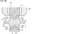
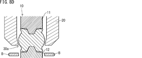
図8A~図8Dは、本発明のクランク軸の製造方法によるバリ抜き工程の処理フロー例を示す断面図である。図8Aは鍛造材の配置時の状態を示す。図8Bは鍛造材の保持時の状態を示す。図8Cは刃物型の当接時の状態を示す。図8Dは刃物型の下降終了時の状態を示す。図8A~図8Dは、前記図3Aの線IIIC-IIICの位置に相当する位置の断面図である。
3. Process Flow Example of Deburring Process FIGS. 8A to 8D are cross-sectional views showing an example of a process flow of a deburring process according to the crankshaft manufacturing method of the present invention. FIG. 8A shows a state when the forging material is arranged. FIG. 8B shows a state when the forging material is held. FIG. 8C shows a state when the cutter tool is in contact. FIG. 8D shows a state at the end of the lowering of the blade mold. 8A to 8D are cross-sectional views at positions corresponding to the position of line IIIC-IIIC in FIG. 3A.
図8A~図8Dには、鍛造材30と、上下で一対の保持型10と、刃物型20とを示す。バリ付きの鍛造材30の形状は、前記図3A~図3Cに示す鍛造材30の形状と同様である。図8Aでは、1つの粗ピン部P’とその粗ピン部P’に接続する粗アーム部A’を抽出して示す。
8A to 8D show the forging material 30, a pair of holding molds 10 at the top and bottom, and the blade mold 20. FIG. The shape of the forged material 30 with burrs is the same as the shape of the forged material 30 shown in FIGS. 3A to 3C. In FIG. 8A, one coarse pin portion P ′ and a coarse arm portion A ′ connected to the coarse pin portion P ′ are extracted and shown.
保持型10は、上型11と下型12とからなる。上型11および下型12は、離間および近接するように移動可能である。上型11と下型12の間に鍛造材30を配置した状態で、上型11と下型12とを近接させることにより、鍛造材30を上型11と下型12の間に挟んで保持する。
The holding mold 10 includes an upper mold 11 and a lower mold 12. The upper mold | type 11 and the lower mold | type 12 are movable so that it may space apart and adjoin. The forging material 30 is held between the upper die 11 and the lower die 12 by bringing the upper die 11 and the lower die 12 close to each other with the forging material 30 disposed between the upper die 11 and the lower die 12. To do.
上型11および下型12には、鍛造材30を挟んで保持するとともに突出する余肉部を変形させるため、それぞれ型彫刻部が彫り込まれている。それらの型彫刻部には、クランク軸の最終製品形状が反映されている。刃物型20は、最終製品の輪郭形状に沿ってバリBを除去するための形状を有する。すなわち、刃物型20の先端部の輪郭は、最終製品のバリ線に対応している。
The upper mold 11 and the lower mold 12 are each engraved with a mold engraving portion for holding the forging material 30 and deforming the protruding surplus portion. These mold engravings reflect the final product shape of the crankshaft. The blade mold 20 has a shape for removing the burrs B along the contour shape of the final product. That is, the outline of the tip of the blade mold 20 corresponds to the burr line of the final product.
このような保持型10および刃物型20を用いる処理フロー例では、先ず、上型11および下型12を離間させるとともに、刃物型20を上方に退避させる。この状態で、図8Aに示すように、バリ付きの鍛造材30を上型11と下型12の間に配置する。
In the processing flow example using the holding mold 10 and the cutter mold 20 as described above, first, the upper mold 11 and the lower mold 12 are separated from each other, and the cutter mold 20 is retracted upward. In this state, as shown in FIG. 8A, the forged material 30 with burrs is disposed between the upper die 11 and the lower die 12.
続いて、上型11と下型12とが近接するように移動させる。より具体的には、上型11を下降させる。これにより、図8Bに示すように、上型11および下型12を鍛造材30と当接させ、上型11と下型12とで鍛造材30を挟んで保持する。
Subsequently, the upper mold 11 and the lower mold 12 are moved so as to be close to each other. More specifically, the upper mold 11 is lowered. As a result, as shown in FIG. 8B, the upper die 11 and the lower die 12 are brought into contact with the forging material 30, and the forging material 30 is held between the upper die 11 and the lower die 12.
本実施形態の鍛造クランク軸の製造方法では、一対の保持型10で鍛造材30を挟む際に、保持型10により、鍛造材30の第1余肉部AaaおよびAbaを圧下して変形させる。例えば、保持型10によって第1余肉部AaaおよびAbaを押し潰す、または、保持型10に沿って第1余肉部AaaおよびAbaを粗ジャーナル部側に折り曲げる。これらにより、第1余肉部を保持型10の型彫刻部に沿う形状とし、粗ジャーナル部側に張り出させる。その結果、粗アーム部Aの粗ピン部P近傍の両側部Aa’およびAb’の厚みが増加する。このため、得られるクランク軸は、アーム部Aのピン部P近傍の両側部AaおよびAbで厚みが厚くなる。図8Bの鍛造材30の各部の形状は、最終製品である鍛造クランク軸の各部の形状に実質的に対応する。そのため、図8Bでは、鍛造材30の符号を、最終製品である鍛造クランク軸の各部の符号と同じとしている(図9Bにおいても同様である)。
In the method for manufacturing a forged crankshaft according to the present embodiment, when the forged material 30 is sandwiched between the pair of holding dies 10, the first surplus portions Aaa and Aba of the forged material 30 are pressed down and deformed by the holding dies 10. For example, the first surplus portions Aaa and Aba are crushed by the holding die 10, or the first surplus portions Aaa and Aba are bent along the holding die 10 toward the coarse journal portion. As a result, the first surplus portion is formed in a shape along the mold engraving portion of the holding die 10 and protrudes toward the coarse journal portion. As a result, the thickness of both side portions Aa ′ and Ab ′ in the vicinity of the rough pin portion P of the rough arm portion A increases. For this reason, the obtained crankshaft becomes thick at both side portions Aa and Ab near the pin portion P of the arm portion A. The shape of each part of the forged material 30 in FIG. 8B substantially corresponds to the shape of each part of the forged crankshaft that is the final product. Therefore, in FIG. 8B, the code | symbol of the forged material 30 is made the same as the code | symbol of each part of the forged crankshaft which is a final product (it is the same also in FIG. 9B).
引き続き、保持型10で鍛造材30を保持した状態で、刃物型20を圧下方向に移動させる。より具体的には、刃物型20を下降させる。これに伴い、図8Cに示すように、刃物型20が鍛造材30のバリBと当接し、図8Dに示すように、バリBが切断されて鍛造材30から除去される。その結果、バリ無しの鍛造材30aが得られる。
Subsequently, with the forging material 30 held by the holding die 10, the blade die 20 is moved in the reduction direction. More specifically, the blade mold 20 is lowered. Along with this, as shown in FIG. 8C, the blade tool 20 abuts against the burrs B of the forging material 30, and the burrs B are cut and removed from the forging material 30 as shown in FIG. 8D. As a result, a forged material 30a without burrs is obtained.
刃物型20の下降終了後、刃物型20を上昇させて退避させるとともに、保持型10の上型11と下型12とを離間させる。そして、バリ無しの鍛造材30aを取り出す。
After the lowering of the blade mold 20 is finished, the blade mold 20 is raised and retracted, and the upper mold 11 and the lower mold 12 of the holding mold 10 are separated. And the forging material 30a without a burr | flash is taken out.
ここで、バリ付き鍛造材30は、図8Aに示すように、粗アーム部A’の粗ジャーナル部側の表面のうち、粗ピン部P’近傍の両側部Aa’およびAb’の内側領域As’に、バリ抜き後の凹みの底面形状と合致する表面形状を有する。その内側領域As’の表面形状は、バリ抜き工程の過程で維持される。一方で、保持型10で鍛造材30を挟む際に、粗アーム部A’の粗ピン部P’近傍の両側部Aa’およびAb’で厚みが厚くなる。その結果、アーム部Aのジャーナル部J側の表面に凹みが設けられる。
Here, as shown in FIG. 8A, the forged material 30 with burrs is an inner region As of both side portions Aa ′ and Ab ′ in the vicinity of the rough pin portion P ′ in the surface of the rough arm portion A ′ on the rough journal portion side. It has a surface shape that matches the bottom shape of the dent after deburring. The surface shape of the inner region As' is maintained during the deburring process. On the other hand, when the forging material 30 is sandwiched between the holding dies 10, the thicknesses increase at both side portions Aa 'and Ab' in the vicinity of the rough pin portion P 'of the rough arm portion A'. As a result, a recess is provided on the surface of the arm portion A on the journal portion J side.
このような本実施形態の鍛造クランク軸の製造方法によれば、アーム部Aのピン部P近傍の側部AaおよびAbの厚みを厚くしつつ、アーム部Aのジャーナル部J側の表面に凹みを設けることが可能となる。このため、本実施形態の鍛造クランク軸の製造方法は、軽量化と剛性確保を同時に図った鍛造クランク軸を製造できる。
According to the manufacturing method of the forged crankshaft of this embodiment, the thickness of the side portions Aa and Ab in the vicinity of the pin portion P of the arm portion A is increased while the surface of the arm portion A on the journal portion J side is recessed. Can be provided. For this reason, the forged crankshaft manufacturing method of the present embodiment can manufacture a forged crankshaft that simultaneously achieves weight reduction and rigidity.
また、本実施形態の鍛造クランク軸の製造方法は、保持型によって第1余肉部AaaおよびAbaを変形させることにより、粗アーム部の粗ピン部近傍の側部Aa’およびAb’の厚みを増加させる。その結果、アーム部Aのジャーナル部J側の表面に凹みが設けられる。このため、本実施形態の鍛造クランク軸の製造方法は、既存の設備や金型を利用して簡便に行える。
Further, in the method of manufacturing the forged crankshaft of the present embodiment, the thickness of the side portions Aa ′ and Ab ′ in the vicinity of the rough pin portion of the rough arm portion is changed by deforming the first surplus portion Aaa and Aba with the holding die. increase. As a result, a recess is provided on the surface of the arm portion A on the journal portion J side. For this reason, the manufacturing method of the forged crankshaft of this embodiment can be simply performed using the existing equipment and metal mold | die.
加えて、本実施形態の鍛造クランク軸の製造方法は、バリ抜き工程で保持型10によって鍛造材30を挟む際に、第1余肉部を保持型によって変形させ、粗アーム部の粗ピン部近傍の側部の厚みを増加させる。このため、従来の製造工程を変更する必要がない。
In addition, in the method for manufacturing a forged crankshaft according to the present embodiment, when the forging material 30 is sandwiched by the holding die 10 in the deburring process, the first surplus portion is deformed by the holding die, and the rough pin portion of the rough arm portion is formed. Increase the thickness of nearby sides. For this reason, it is not necessary to change the conventional manufacturing process.
本実施形態の鍛造クランク軸の製造方法は、前記図4A~図4Dに示すような第2構成例の鍛造クランク軸を対象とすることもできる。この場合、バリ付きの鍛造材では、粗ウエイト部を一体で有する粗アーム部が、前記図5A~図5Cに示すような第2余肉部AcaおよびAdaを有することが好ましい。その第2余肉部AcaおよびAdaは、粗ウエイト部を一体で有する粗アーム部A’の粗ジャーナル部J’近傍の側部Ac’およびAd’の外周から突出する。
The method for manufacturing a forged crankshaft according to the present embodiment can be applied to the forged crankshaft of the second configuration example as shown in FIGS. 4A to 4D. In this case, in the forged material with burrs, it is preferable that the coarse arm portion integrally having the coarse weight portion has the second surplus portions Aca and Ada as shown in FIGS. 5A to 5C. The second surplus portions Aca and Ada project from the outer periphery of the side portions Ac 'and Ad' in the vicinity of the coarse journal portion J 'of the coarse arm portion A' integrally having the coarse weight portion.
加えて、バリ抜き工程では、保持型によって鍛造材を挟む際に、保持型により、第1余肉部AaaおよびAbaを変形させるのみならず、粗ウエイト部を一体で有する粗アーム部A’の第2余肉部AcaおよびAdaも変形させて粗ピン部側に張り出させることが好ましい。これにより、粗ウエイト部を一体で有する粗アーム部A’の粗ジャーナル部J’近傍の側部Ac’およびAd’でも厚みを増加させる。第2余肉部の変形は、例えば、押し潰し加工または折り曲げ加工によって行うことができる。その結果、前記図4A~図4Dに示すような、剛性を確保しつつ、より軽量化を図ったクランク軸を得ることができる。
In addition, in the deburring process, when the forging material is sandwiched by the holding mold, the holding mold not only deforms the first surplus portions Aaa and Aba, but also the coarse arm portion A ′ having the coarse weight portion integrally. It is preferable that the second surplus portions Aca and Ada are also deformed and protruded toward the rough pin portion. As a result, the thickness of the side portions Ac ′ and Ad ′ in the vicinity of the coarse journal portion J ′ of the coarse arm portion A ′ integrally having the coarse weight portion is also increased. The deformation of the second surplus portion can be performed, for example, by crushing or bending. As a result, it is possible to obtain a crankshaft that is lighter while ensuring rigidity as shown in FIGS. 4A to 4D.
本実施形態の鍛造クランク軸の製造方法は、前記図6Aおよび図6Bに示すような第3構成例の鍛造クランク軸を対象とすることもできる。その鍛造クランク軸は、アーム部Aのうちの一部にウエイト部を一体で有し、すなわち、残りのアーム部Aがウエイト部を有することなく、ウエイト無しアーム部である。
The method for manufacturing a forged crankshaft according to the present embodiment can be applied to the forged crankshaft of the third configuration example as shown in FIGS. 6A and 6B. The forged crankshaft has a weight portion integrally with a part of the arm portion A, that is, the remaining arm portion A is a weightless arm portion without having a weight portion.
この場合、バリ付きの鍛造材では、ウエイト無し粗アーム部が、前記図7Aおよび図7Bに示すような第2余肉部AcaおよびAdaを有することが好ましい。その第2余肉部AcaおよびAdaは、ウエイト無し粗アーム部A’の粗ジャーナル部J’近傍の側部Ac’およびAd’の外周から突出する。
In this case, in the forged material with burrs, the coarse arm portion without weight preferably has the second surplus portions Aca and Ada as shown in FIGS. 7A and 7B. The second surplus portions Aca and Ada protrude from the outer peripheries of the side portions Ac ′ and Ad ′ in the vicinity of the coarse journal portion J ′ of the unweighted coarse arm portion A ′.
加えて、バリ抜き工程では、保持型によって鍛造材を挟む際に、保持型により、第1余肉部AaaおよびAbaを変形させるのみならず、ウエイト無し粗アーム部の第2余肉部AcaおよびAdaも変形させて粗ピン部側に張り出させることが好ましい。これにより、ウエイト無し粗アーム部A’の粗ジャーナル部J’近傍の両側部Ac’およびAd’でも厚みを増加させる。第2余肉部の変形は、例えば、押し潰し加工または折り曲げ加工によって行うことができる。その結果、前記図6Aおよび図6Bに示すような、剛性を確保しつつ、より軽量化を図ったクランク軸を得ることができる。
In addition, in the deburring process, when the forging material is sandwiched by the holding die, the first surplus portion Aaa and Aba are not only deformed by the holding die, but also the second surplus portion Aca of the weightless coarse arm portion and It is preferable that Ada is also deformed and protrudes toward the rough pin portion. As a result, the thickness is increased at both side portions Ac ′ and Ad ′ in the vicinity of the coarse journal portion J ′ of the coarse arm portion A ′ having no weight. The deformation of the second surplus portion can be performed, for example, by crushing or bending. As a result, it is possible to obtain a crankshaft that is lighter while securing rigidity as shown in FIGS. 6A and 6B.
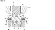
本実施形態のバリ抜き工程において、保持型とともに、上述した支持部材を用いてもよい。保持型とともに支持部材を用いるバリ抜き工程の一例について、図9A~図9Dを用いて説明する。図9A、図9B、図9C、および図9Dはそれぞれ、図8A、図8B、図8C、および図8Dに対応している。図8A~図8Dで説明した事項については、重複する説明を省略する場合がある。
In the deburring process of this embodiment, the support member described above may be used together with the holding mold. An example of a deburring process using a supporting member together with the holding mold will be described with reference to FIGS. 9A to 9D. 9A, 9B, 9C, and 9D correspond to FIGS. 8A, 8B, 8C, and 8D, respectively. 8A to 8D may not be described repeatedly.
以下では、図3A~図3Cに示した第1構成例の鍛造材30に対してバリ抜き工程を行う一例について説明する。しかし、他の鍛造材(例えば第2構成例および第3構成例の鍛造材)についても、同様に、支持部材を用いてバリ抜き工程を行うことができる。
Hereinafter, an example in which a deburring process is performed on the forged material 30 of the first configuration example illustrated in FIGS. 3A to 3C will be described. However, for other forged materials (for example, the forged materials of the second configuration example and the third configuration example), the deburring step can be similarly performed using the support member.
この実施形態では、バリBの下面を支持する複数(例えば4つ)の支持部材40を用いる。なお、以下の図では、鍛造材の一部のみを図示しているため、図示される支持部材40は2つのみとなっている。支持部材40は、上下に移動可能である。
In this embodiment, a plurality of (for example, four) support members 40 that support the lower surface of the burr B are used. In the following drawings, only a part of the forging material is illustrated, and therefore, only two support members 40 are illustrated. The support member 40 can move up and down.
先ず、図9Aに示すように、バリ付きの鍛造材30と金型とを配置する。具体的には、離間している上型11と下型12との間に鍛造材30を配置する。このとき、刃物型20は上方に退避させておく。鍛造材30のバリBの下面は、支持部材40によって安定に支持されている。支持部材40は、バリBが水平になるように鍛造材30を支持する。図9Aの状態では、鍛造材30と保持型10とは接触していない。
First, as shown in FIG. 9A, a forged material 30 with a burr and a mold are arranged. Specifically, the forging material 30 is disposed between the upper die 11 and the lower die 12 that are separated from each other. At this time, the blade mold 20 is retracted upward. The lower surface of the burr B of the forged material 30 is stably supported by the support member 40. The support member 40 supports the forged material 30 so that the burr B is horizontal. In the state of FIG. 9A, the forging material 30 and the holding die 10 are not in contact.
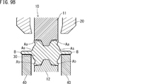
続いて、上型11と下型12とを近接させる。より具体的には、上型11を下降させる。これにより、図9Bに示すように、上型11および下型12を鍛造材30と当接させ、上型11と下型12とで鍛造材30を挟んで保持する。
Subsequently, the upper mold 11 and the lower mold 12 are brought close to each other. More specifically, the upper mold 11 is lowered. As a result, as shown in FIG. 9B, the upper die 11 and the lower die 12 are brought into contact with the forging material 30, and the forging material 30 is held between the upper die 11 and the lower die 12.
上述したように、本実施形態の製造方法では、一対の保持型10で鍛造材30を挟む際に、保持型10により、鍛造材30の第1余肉部AaaおよびAbaを圧下して変形させる。具体的には、第1余肉部を保持型10の型彫刻部に沿う形状とし、粗ジャーナル部側に張り出させる。その結果、粗アーム部A’の粗ピン部P’近傍の両側部Aa’およびAb’の厚みが増加する。
As described above, in the manufacturing method of the present embodiment, when the forging material 30 is sandwiched between the pair of holding dies 10, the first surplus portions Aaa and Aba of the forging material 30 are pressed down and deformed by the holding die 10. . Specifically, the first surplus portion is formed in a shape along the mold engraving portion of the holding die 10 and protrudes toward the coarse journal portion. As a result, the thickness of both side portions Aa 'and Ab' near the rough pin portion P 'of the rough arm portion A' increases.
上型11を下降させて鍛造材30を保持する場合、上型11が先ず鍛造材30と接触し、鍛造材30の下降に伴って下型12と鍛造材30とが接触する。さらに、上型11が下降するのに伴って、鍛造材30が変形される。この場合、保持型10の動作(上型11の下降)に伴ってバリBが下降する。そのため、支持部材40は、バリBの下降に伴って、バリBの下面を支持している状態を維持しながら下降する。換言すれば、支持部材40は、保持型10の動作に伴って位置が変動するバリBに追従して移動する。
When the upper die 11 is lowered and the forging material 30 is held, the upper die 11 first comes into contact with the forging material 30, and the lower die 12 and the forging material 30 come into contact with the lowering of the forging material 30. Furthermore, the forging material 30 is deformed as the upper die 11 is lowered. In this case, the burr B is lowered along with the operation of the holding die 10 (lowering of the upper die 11). Therefore, the support member 40 is lowered while maintaining the state of supporting the lower surface of the burr B as the burr B is lowered. In other words, the support member 40 moves following the burr B whose position varies with the operation of the holding mold 10.
鍛造材30の第1余肉部AaaおよびAbaは保持型10によって変形される。そのため、バリ抜き工程の初期の段階では第1余肉部AaaおよびAbaの形状と保持型10の形状とは一致しない。従って、図9Aの段階で支持部材40を用いずに鍛造材30を下型12のみで支えた場合、鍛造材30の姿勢が安定しない場合がある。鍛造材30の姿勢が安定しない場合、その後の保持型10による保持および成形、並びに、刃物型20によるバリ抜き工程が安定して行えない。そのため、バリ抜き工程の際に支持部材40を用いることは、安定した加工を行うために特に好ましい。
The first surplus portions Aaa and Aba of the forging material 30 are deformed by the holding die 10. Therefore, at the initial stage of the deburring process, the shapes of the first surplus portions Aaa and Aba and the shape of the holding mold 10 do not match. Therefore, when the forged material 30 is supported only by the lower mold 12 without using the support member 40 in the stage of FIG. 9A, the posture of the forged material 30 may not be stable. When the posture of the forged material 30 is not stable, the subsequent holding and forming by the holding die 10 and the deburring process by the blade die 20 cannot be stably performed. Therefore, it is particularly preferable to use the support member 40 during the deburring process in order to perform stable processing.
次に、保持型10によって鍛造材30を保持した状態で刃物型20を下降させる。その結果、先ず、図9Cに示すように刃物型20が鍛造材30のバリBと当接する。その後、図9Dに示すようにバリBが切断されて鍛造材30から除去される。このようにして、バリ無しの鍛造材30aが得られる。
Next, the blade die 20 is lowered while the forging material 30 is held by the holding die 10. As a result, first, as shown in FIG. 9C, the cutter tool 20 comes into contact with the burr B of the forged material 30. Thereafter, as shown in FIG. 9D, the burr B is cut and removed from the forging material 30. In this way, a forged material 30a without burrs is obtained.
バリBの下降とともに支持部材40も下降する。なお、保持型10による鍛造材30の変形が完了した後は、鍛造材30の位置および姿勢が安定する。そのため、保持型10による鍛造材30の変形が完了した後であってバリ抜き工程を開始する前に、支持部材40だけを下降させてもよい。
¡The support member 40 also descends as the burr B descends. In addition, after the deformation of the forging material 30 by the holding die 10 is completed, the position and posture of the forging material 30 are stabilized. Therefore, after the deformation of the forged material 30 by the holding die 10 is completed and before the deburring process is started, only the support member 40 may be lowered.
図9Dに示される下降した支持部材40は、刃物型20が上方に戻った後、所定の工程までは下降したままの状態にあってもよい。例えば、バリ抜き工程後の鍛造材30aが上型11と下型12との間から搬出されるまでは、支持部材40を下降した位置で停止させておいてもよい。下降した位置で支持部材40を停止させる機構に限定はなく、公知の機構を適用してもよい。
The support member 40 lowered in FIG. 9D may remain in a lowered state until a predetermined process after the blade mold 20 returns upward. For example, the support member 40 may be stopped at the lowered position until the forged material 30a after the deburring step is unloaded from between the upper die 11 and the lower die 12. The mechanism for stopping the support member 40 at the lowered position is not limited, and a known mechanism may be applied.
刃物型20の下降終了後、刃物型20を上昇させて退避させるとともに、保持型10の上型11と下型12とを離間させる。そして、バリ無しの鍛造材30aを取り出す。
After the lowering of the blade mold 20 is finished, the blade mold 20 is raised and retracted, and the upper mold 11 and the lower mold 12 of the holding mold 10 are separated. And the forging material 30a without a burr | flash is taken out.
図9A~図9Dでは、支持部材40を用いて第1構成例の鍛造材30のバリ抜き工程を行う一例について説明した。他の鍛造材30についても、同様に行うことができる。第2構成例の鍛造材30について支持部材40を用いてバリ抜き工程を行う場合について、支持部材40の配置の一例を図10に示す。図10は、図9Aの工程に対応する。
9A to 9D, an example in which the deburring process for the forged material 30 of the first configuration example is performed using the support member 40 has been described. The other forgings 30 can be similarly performed. An example of the arrangement of the support members 40 is shown in FIG. 10 in the case where the deburring process is performed on the forged material 30 of the second configuration example using the support members 40. FIG. 10 corresponds to the step of FIG. 9A.
第2構成例の鍛造材30のバリ抜き工程を行う場合、先ず、図10に示すように、バリ付きの鍛造材30を支持部材40で支持する。鍛造材30のバリBの下面は、複数の支持部材40によって支持される。その後は、図9B~図9Dで説明した工程と同様に、バリ抜き工程が行われる。このようにして、支持部材40を用いて、第2構成例の鍛造材30のバリ抜き工程が行われる。第3構成例の鍛造材30のバリ抜き工程も、同様に行うことができる。
When performing the deburring process of the forging material 30 of the second configuration example, first, the forging material 30 with burr is supported by the support member 40 as shown in FIG. The lower surface of the burr B of the forged material 30 is supported by a plurality of support members 40. Thereafter, a deburring process is performed in the same manner as described with reference to FIGS. 9B to 9D. Thus, the deburring process of the forged material 30 of the second configuration example is performed using the support member 40. The deburring process of the forged material 30 of the third configuration example can be performed in the same manner.
第1~第3構成例のクランク軸は、ウエイト部の有無に依拠することなく、複数のアーム部の全部が、ピン部近傍のジャーナル部側の表面に凹みを有する。本実施形態のクランク軸の製造方法では、複数のアーム部の一部が、ピン部近傍のジャーナル部側の表面に凹みを有してもよい。換言すると、鍛造材の複数の粗アーム部の全部または一部が第1余肉部を有すればよい。第1余肉部を設ける粗アーム部は、例えば、アーム部に要求される曲げ剛性やねじり剛性、剛性が必要な部位に基づいて、適宜決定できる。
The crankshafts of the first to third configuration examples do not depend on the presence or absence of the weight portion, and all of the plurality of arm portions have a dent on the surface on the journal portion side in the vicinity of the pin portion. In the crankshaft manufacturing method of the present embodiment, some of the plurality of arm portions may have a dent on the surface of the journal portion side in the vicinity of the pin portion. In other words, all or some of the plurality of rough arm portions of the forged material may have the first surplus portion. The rough arm portion provided with the first surplus portion can be determined as appropriate based on, for example, a portion requiring bending rigidity, torsional rigidity, and rigidity required for the arm part.
前述の通り、ウエイト部を一体で有するアーム部(以下、「ウエイト付きアーム部」ともいう)は、ジャーナル部近傍のピン部側の表面に凹みを有することが好ましい。複数のウエイト付きアーム部を備えるクランク軸において、ウエイト付きアーム部のジャーナル部近傍のピン部側の表面に凹みを設ける場合、ウエイト付きアーム部の全部が、ピン部側の表面に凹みを有してもよい。あるいは、ウエイト付きアーム部の一部が、ピン部側の表面に凹みを有してもよい。換言すると、鍛造材では、複数のウエイト付き粗アーム部の全部または一部が第2余肉部を有してもよい。第2余肉部を設ける粗アーム部は、例えば、アーム部に要求される曲げ剛性やねじり剛性、剛性が必要な部位に基づいて、適宜決定できる。
As described above, the arm portion having the weight portion integrally (hereinafter, also referred to as “arm portion with weight”) preferably has a dent on the surface of the pin portion side in the vicinity of the journal portion. In a crankshaft having a plurality of weighted arm portions, when providing a recess on the surface of the pin portion side near the journal portion of the weighted arm portion, all of the weighted arm portions have a recess on the surface of the pin portion side. May be. Or a part of arm part with a weight may have a dent in the surface at the side of a pin part. In other words, in the forged material, all or part of the plurality of weighted coarse arm portions may have the second surplus portion. The coarse arm portion provided with the second surplus portion can be determined as appropriate based on, for example, a portion requiring bending rigidity, torsional rigidity, and rigidity required for the arm part.
前述の通り、ウエイト無しアーム部は、ジャーナル部近傍のピン部側の表面に凹みを有することが好ましい。複数のウエイト無しアーム部を備えるクランク軸において、ウエイト無しアーム部のジャーナル部近傍のピン部側の表面に凹みを設ける場合、複数のウエイト無しアーム部の全部が、ピン部側の表面に凹みを有してもよい。あるいは、複数のウエイト無しアーム部の一部が、ピン部側の表面に凹みを有してもよい。換言すると、鍛造材の複数のウエイト無し粗アーム部の全部または一部が第2余肉部を有してもよい。第2余肉部を設ける粗アーム部は、例えば、アーム部に要求される曲げ剛性やねじり剛性、剛性が必要な部位に基づいて、適宜決定できる。
As described above, it is preferable that the arm portion without weight has a dent on the surface of the pin portion side near the journal portion. In a crankshaft having a plurality of weightless arm portions, when a recess is provided on the surface of the pin portion side in the vicinity of the journal portion of the weightless arm portion, all of the plurality of weightless arm portions are recessed on the surface of the pin portion side. You may have. Alternatively, some of the plurality of weightless arm portions may have dents on the surface on the pin portion side. In other words, all or some of the plurality of weightless coarse arm portions of the forged material may have the second surplus portion. The coarse arm portion provided with the second surplus portion can be determined as appropriate based on, for example, a portion requiring bending rigidity, torsional rigidity, and rigidity required for the arm part.
前述の第1~第3構成例のように、粗アーム部は、第1余肉部を粗ピン部近傍の両方の側部(両側部)に有してもよく、あるいは、第1余肉部を粗ピン部近傍の一方の側部に有してもよい。粗アーム部が第1余肉部を粗ピン部近傍の一方の側部に有する場合であっても、その第1余肉部を粗ジャーナル部側に張り出させることにより、バリ抜き工程後のアーム部の一方の側部で厚みを増加できる。このため、軽量化しつつ、剛性を確保できる。第1余肉部を設ける粗ピン部近傍の側部は、例えば、アーム部に要求される曲げ剛性やねじり剛性、剛性が必要な部位に基づいて、適宜決定できる。
As in the first to third configuration examples described above, the rough arm portion may have the first surplus portion on both sides (both sides) in the vicinity of the rough pin portion, or the first surplus portion. You may have a part in one side part of the rough pin part vicinity. Even when the rough arm portion has the first surplus portion on one side near the rough pin portion, by projecting the first surplus portion to the rough journal portion side, The thickness can be increased on one side of the arm. For this reason, rigidity can be secured while reducing the weight. The side part in the vicinity of the rough pin part where the first surplus part is provided can be determined as appropriate based on, for example, a part requiring bending rigidity, torsional rigidity, and rigidity required for the arm part.
前述の第2構成例のように、ウエイト付き粗アーム部は、第2余肉部を粗ジャーナル部近傍の両方の側部に有してもよく、あるいは、第2余肉部を粗ジャーナル部近傍の一方の側部に有してもよい。粗アーム部が第2余肉部を粗ジャーナル部近傍の一方の側部に有する場合であっても、その第2余肉部を粗ピン部側に張り出させることにより、バリ抜き工程後のアーム部の一方の側部で厚みを増加できる。第2余肉部を設ける粗ジャーナル部近傍の側部は、例えば、アーム部に要求される曲げ剛性やねじり剛性、剛性が必要な部位に基づいて、適宜決定できる。
As in the second configuration example described above, the weighted coarse arm portion may have the second surplus portion on both side portions in the vicinity of the coarse journal portion, or the second surplus portion may be provided in the coarse journal portion. You may have on one side of the vicinity. Even when the rough arm portion has the second surplus portion on one side near the rough journal portion, the second surplus portion is projected to the rough pin portion side, so that after the deburring step The thickness can be increased on one side of the arm. The side part in the vicinity of the coarse journal part in which the second surplus part is provided can be determined as appropriate based on, for example, a part requiring bending rigidity, torsional rigidity, and rigidity required for the arm part.
前述の第3構成例のように、ウエイト無し粗アーム部は、第2余肉部を粗ジャーナル部近傍の両方の側部に有してもよく、あるいは、第2余肉部を粗ジャーナル部近傍の一方の側部に有してもよい。粗アーム部が第2余肉部を粗ジャーナル部近傍の一方の側部に有する場合であっても、その第2余肉部を粗ピン部側に張り出させることにより、バリ抜き工程後のアーム部の一方の側部で厚みを増加できる。このため、軽量化しつつ、剛性を確保できる。第2余肉部を設ける粗ジャーナル部近傍の側部は、例えば、アーム部に要求される曲げ剛性やねじり剛性、剛性が必要な部位に基づいて、適宜決定できる。
As in the third configuration example described above, the weightless coarse arm portion may have the second surplus portion on both side portions near the coarse journal portion, or the second surplus portion may be provided in the coarse journal portion. You may have on one side of the vicinity. Even when the rough arm portion has the second surplus portion on one side near the rough journal portion, the second surplus portion is projected to the rough pin portion side, so that after the deburring step The thickness can be increased on one side of the arm. For this reason, rigidity can be secured while reducing the weight. The side part in the vicinity of the coarse journal part in which the second surplus part is provided can be determined as appropriate based on, for example, a part requiring bending rigidity, torsional rigidity, and rigidity required for the arm part.