WO2016159143A1 - Electronic device and computer program product - Google Patents
Electronic device and computer program product Download PDFInfo
- Publication number
- WO2016159143A1 WO2016159143A1 PCT/JP2016/060496 JP2016060496W WO2016159143A1 WO 2016159143 A1 WO2016159143 A1 WO 2016159143A1 JP 2016060496 W JP2016060496 W JP 2016060496W WO 2016159143 A1 WO2016159143 A1 WO 2016159143A1
- Authority
- WO
- WIPO (PCT)
- Prior art keywords
- image
- imaging
- unit
- electronic device
- imaging condition
- Prior art date
Links
- 238000004590 computer program Methods 0.000 title claims description 5
- 238000003384 imaging method Methods 0.000 claims description 393
- 238000012545 processing Methods 0.000 claims description 97
- 238000000034 method Methods 0.000 claims description 22
- 230000008569 process Effects 0.000 claims description 13
- 235000019557 luminance Nutrition 0.000 description 61
- 239000004973 liquid crystal related substance Substances 0.000 description 39
- 230000000875 corresponding effect Effects 0.000 description 30
- 238000001514 detection method Methods 0.000 description 30
- 230000004048 modification Effects 0.000 description 26
- 238000012986 modification Methods 0.000 description 26
- 238000009825 accumulation Methods 0.000 description 23
- 238000004891 communication Methods 0.000 description 21
- 238000010586 diagram Methods 0.000 description 15
- 238000004364 calculation method Methods 0.000 description 14
- 230000008859 change Effects 0.000 description 13
- 230000000694 effects Effects 0.000 description 11
- 238000012546 transfer Methods 0.000 description 11
- 230000003287 optical effect Effects 0.000 description 7
- 230000004044 response Effects 0.000 description 6
- 241000724291 Tobacco streak virus Species 0.000 description 3
- 239000002131 composite material Substances 0.000 description 3
- 238000010411 cooking Methods 0.000 description 3
- 238000005516 engineering process Methods 0.000 description 3
- 230000002093 peripheral effect Effects 0.000 description 3
- 230000011218 segmentation Effects 0.000 description 3
- 230000035945 sensitivity Effects 0.000 description 3
- 241001465754 Metazoa Species 0.000 description 2
- 230000002457 bidirectional effect Effects 0.000 description 2
- 238000006243 chemical reaction Methods 0.000 description 2
- 238000012937 correction Methods 0.000 description 2
- 230000003247 decreasing effect Effects 0.000 description 2
- 238000005096 rolling process Methods 0.000 description 2
- 241000196324 Embryophyta Species 0.000 description 1
- 241000282326 Felis catus Species 0.000 description 1
- 235000006961 Fumaria officinalis Nutrition 0.000 description 1
- 244000044980 Fumaria officinalis Species 0.000 description 1
- 238000003491 array Methods 0.000 description 1
- 230000004397 blinking Effects 0.000 description 1
- 239000003086 colorant Substances 0.000 description 1
- 230000002596 correlated effect Effects 0.000 description 1
- 238000009792 diffusion process Methods 0.000 description 1
- 230000004907 flux Effects 0.000 description 1
- 230000006870 function Effects 0.000 description 1
- 238000005286 illumination Methods 0.000 description 1
- 239000011159 matrix material Substances 0.000 description 1
- 238000002844 melting Methods 0.000 description 1
- 230000008018 melting Effects 0.000 description 1
- 239000000203 mixture Substances 0.000 description 1
- 238000002161 passivation Methods 0.000 description 1
- 235000012736 patent blue V Nutrition 0.000 description 1
- 239000012071 phase Substances 0.000 description 1
- 238000005070 sampling Methods 0.000 description 1
- 229910052710 silicon Inorganic materials 0.000 description 1
- 239000010703 silicon Substances 0.000 description 1
- 229910000679 solder Inorganic materials 0.000 description 1
- 239000007790 solid phase Substances 0.000 description 1
- BPJYAXCTOHRFDQ-UHFFFAOYSA-L tetracopper;2,4,6-trioxido-1,3,5,2,4,6-trioxatriarsinane;diacetate Chemical compound [Cu+2].[Cu+2].[Cu+2].[Cu+2].CC([O-])=O.CC([O-])=O.[O-][As]1O[As]([O-])O[As]([O-])O1.[O-][As]1O[As]([O-])O[As]([O-])O1 BPJYAXCTOHRFDQ-UHFFFAOYSA-L 0.000 description 1
- 230000007704 transition Effects 0.000 description 1
Images


Classifications
-
- H—ELECTRICITY
- H04—ELECTRIC COMMUNICATION TECHNIQUE
- H04N—PICTORIAL COMMUNICATION, e.g. TELEVISION
- H04N9/00—Details of colour television systems
- H04N9/64—Circuits for processing colour signals
-
- G—PHYSICS
- G03—PHOTOGRAPHY; CINEMATOGRAPHY; ANALOGOUS TECHNIQUES USING WAVES OTHER THAN OPTICAL WAVES; ELECTROGRAPHY; HOLOGRAPHY
- G03B—APPARATUS OR ARRANGEMENTS FOR TAKING PHOTOGRAPHS OR FOR PROJECTING OR VIEWING THEM; APPARATUS OR ARRANGEMENTS EMPLOYING ANALOGOUS TECHNIQUES USING WAVES OTHER THAN OPTICAL WAVES; ACCESSORIES THEREFOR
- G03B15/00—Special procedures for taking photographs; Apparatus therefor
-
- G—PHYSICS
- G03—PHOTOGRAPHY; CINEMATOGRAPHY; ANALOGOUS TECHNIQUES USING WAVES OTHER THAN OPTICAL WAVES; ELECTROGRAPHY; HOLOGRAPHY
- G03B—APPARATUS OR ARRANGEMENTS FOR TAKING PHOTOGRAPHS OR FOR PROJECTING OR VIEWING THEM; APPARATUS OR ARRANGEMENTS EMPLOYING ANALOGOUS TECHNIQUES USING WAVES OTHER THAN OPTICAL WAVES; ACCESSORIES THEREFOR
- G03B7/00—Control of exposure by setting shutters, diaphragms or filters, separately or conjointly
- G03B7/08—Control effected solely on the basis of the response, to the intensity of the light received by the camera, of a built-in light-sensitive device
- G03B7/091—Digital circuits
-
- G—PHYSICS
- G06—COMPUTING; CALCULATING OR COUNTING
- G06V—IMAGE OR VIDEO RECOGNITION OR UNDERSTANDING
- G06V10/00—Arrangements for image or video recognition or understanding
- G06V10/10—Image acquisition
-
- G—PHYSICS
- G06—COMPUTING; CALCULATING OR COUNTING
- G06V—IMAGE OR VIDEO RECOGNITION OR UNDERSTANDING
- G06V10/00—Arrangements for image or video recognition or understanding
- G06V10/40—Extraction of image or video features
- G06V10/50—Extraction of image or video features by performing operations within image blocks; by using histograms, e.g. histogram of oriented gradients [HoG]; by summing image-intensity values; Projection analysis
-
- G—PHYSICS
- G06—COMPUTING; CALCULATING OR COUNTING
- G06V—IMAGE OR VIDEO RECOGNITION OR UNDERSTANDING
- G06V10/00—Arrangements for image or video recognition or understanding
- G06V10/40—Extraction of image or video features
- G06V10/56—Extraction of image or video features relating to colour
-
- H—ELECTRICITY
- H01—ELECTRIC ELEMENTS
- H01L—SEMICONDUCTOR DEVICES NOT COVERED BY CLASS H10
- H01L27/00—Devices consisting of a plurality of semiconductor or other solid-state components formed in or on a common substrate
- H01L27/14—Devices consisting of a plurality of semiconductor or other solid-state components formed in or on a common substrate including semiconductor components sensitive to infrared radiation, light, electromagnetic radiation of shorter wavelength or corpuscular radiation and specially adapted either for the conversion of the energy of such radiation into electrical energy or for the control of electrical energy by such radiation
- H01L27/144—Devices controlled by radiation
- H01L27/146—Imager structures
- H01L27/14601—Structural or functional details thereof
- H01L27/1462—Coatings
- H01L27/14621—Colour filter arrangements
-
- H—ELECTRICITY
- H01—ELECTRIC ELEMENTS
- H01L—SEMICONDUCTOR DEVICES NOT COVERED BY CLASS H10
- H01L27/00—Devices consisting of a plurality of semiconductor or other solid-state components formed in or on a common substrate
- H01L27/14—Devices consisting of a plurality of semiconductor or other solid-state components formed in or on a common substrate including semiconductor components sensitive to infrared radiation, light, electromagnetic radiation of shorter wavelength or corpuscular radiation and specially adapted either for the conversion of the energy of such radiation into electrical energy or for the control of electrical energy by such radiation
- H01L27/144—Devices controlled by radiation
- H01L27/146—Imager structures
- H01L27/14601—Structural or functional details thereof
- H01L27/14625—Optical elements or arrangements associated with the device
- H01L27/14627—Microlenses
-
- H—ELECTRICITY
- H01—ELECTRIC ELEMENTS
- H01L—SEMICONDUCTOR DEVICES NOT COVERED BY CLASS H10
- H01L27/00—Devices consisting of a plurality of semiconductor or other solid-state components formed in or on a common substrate
- H01L27/14—Devices consisting of a plurality of semiconductor or other solid-state components formed in or on a common substrate including semiconductor components sensitive to infrared radiation, light, electromagnetic radiation of shorter wavelength or corpuscular radiation and specially adapted either for the conversion of the energy of such radiation into electrical energy or for the control of electrical energy by such radiation
- H01L27/144—Devices controlled by radiation
- H01L27/146—Imager structures
- H01L27/14601—Structural or functional details thereof
- H01L27/1464—Back illuminated imager structures
-
- H—ELECTRICITY
- H04—ELECTRIC COMMUNICATION TECHNIQUE
- H04N—PICTORIAL COMMUNICATION, e.g. TELEVISION
- H04N23/00—Cameras or camera modules comprising electronic image sensors; Control thereof
-
- H—ELECTRICITY
- H04—ELECTRIC COMMUNICATION TECHNIQUE
- H04N—PICTORIAL COMMUNICATION, e.g. TELEVISION
- H04N23/00—Cameras or camera modules comprising electronic image sensors; Control thereof
- H04N23/60—Control of cameras or camera modules
-
- H—ELECTRICITY
- H04—ELECTRIC COMMUNICATION TECHNIQUE
- H04N—PICTORIAL COMMUNICATION, e.g. TELEVISION
- H04N23/00—Cameras or camera modules comprising electronic image sensors; Control thereof
- H04N23/60—Control of cameras or camera modules
- H04N23/62—Control of parameters via user interfaces
-
- H—ELECTRICITY
- H04—ELECTRIC COMMUNICATION TECHNIQUE
- H04N—PICTORIAL COMMUNICATION, e.g. TELEVISION
- H04N23/00—Cameras or camera modules comprising electronic image sensors; Control thereof
- H04N23/60—Control of cameras or camera modules
- H04N23/63—Control of cameras or camera modules by using electronic viewfinders
- H04N23/631—Graphical user interfaces [GUI] specially adapted for controlling image capture or setting capture parameters
- H04N23/632—Graphical user interfaces [GUI] specially adapted for controlling image capture or setting capture parameters for displaying or modifying preview images prior to image capturing, e.g. variety of image resolutions or capturing parameters
-
- H—ELECTRICITY
- H04—ELECTRIC COMMUNICATION TECHNIQUE
- H04N—PICTORIAL COMMUNICATION, e.g. TELEVISION
- H04N23/00—Cameras or camera modules comprising electronic image sensors; Control thereof
- H04N23/60—Control of cameras or camera modules
- H04N23/63—Control of cameras or camera modules by using electronic viewfinders
- H04N23/633—Control of cameras or camera modules by using electronic viewfinders for displaying additional information relating to control or operation of the camera
- H04N23/635—Region indicators; Field of view indicators
-
- H—ELECTRICITY
- H04—ELECTRIC COMMUNICATION TECHNIQUE
- H04N—PICTORIAL COMMUNICATION, e.g. TELEVISION
- H04N23/00—Cameras or camera modules comprising electronic image sensors; Control thereof
- H04N23/60—Control of cameras or camera modules
- H04N23/67—Focus control based on electronic image sensor signals
- H04N23/673—Focus control based on electronic image sensor signals based on contrast or high frequency components of image signals, e.g. hill climbing method
-
- H—ELECTRICITY
- H04—ELECTRIC COMMUNICATION TECHNIQUE
- H04N—PICTORIAL COMMUNICATION, e.g. TELEVISION
- H04N23/00—Cameras or camera modules comprising electronic image sensors; Control thereof
- H04N23/70—Circuitry for compensating brightness variation in the scene
- H04N23/71—Circuitry for evaluating the brightness variation
-
- H—ELECTRICITY
- H04—ELECTRIC COMMUNICATION TECHNIQUE
- H04N—PICTORIAL COMMUNICATION, e.g. TELEVISION
- H04N23/00—Cameras or camera modules comprising electronic image sensors; Control thereof
- H04N23/70—Circuitry for compensating brightness variation in the scene
- H04N23/72—Combination of two or more compensation controls
-
- H—ELECTRICITY
- H04—ELECTRIC COMMUNICATION TECHNIQUE
- H04N—PICTORIAL COMMUNICATION, e.g. TELEVISION
- H04N23/00—Cameras or camera modules comprising electronic image sensors; Control thereof
- H04N23/70—Circuitry for compensating brightness variation in the scene
- H04N23/73—Circuitry for compensating brightness variation in the scene by influencing the exposure time
-
- H—ELECTRICITY
- H04—ELECTRIC COMMUNICATION TECHNIQUE
- H04N—PICTORIAL COMMUNICATION, e.g. TELEVISION
- H04N23/00—Cameras or camera modules comprising electronic image sensors; Control thereof
- H04N23/70—Circuitry for compensating brightness variation in the scene
- H04N23/76—Circuitry for compensating brightness variation in the scene by influencing the image signals
-
- H—ELECTRICITY
- H04—ELECTRIC COMMUNICATION TECHNIQUE
- H04N—PICTORIAL COMMUNICATION, e.g. TELEVISION
- H04N25/00—Circuitry of solid-state image sensors [SSIS]; Control thereof
- H04N25/10—Circuitry of solid-state image sensors [SSIS]; Control thereof for transforming different wavelengths into image signals
- H04N25/11—Arrangement of colour filter arrays [CFA]; Filter mosaics
- H04N25/13—Arrangement of colour filter arrays [CFA]; Filter mosaics characterised by the spectral characteristics of the filter elements
- H04N25/134—Arrangement of colour filter arrays [CFA]; Filter mosaics characterised by the spectral characteristics of the filter elements based on three different wavelength filter elements
-
- H—ELECTRICITY
- H04—ELECTRIC COMMUNICATION TECHNIQUE
- H04N—PICTORIAL COMMUNICATION, e.g. TELEVISION
- H04N25/00—Circuitry of solid-state image sensors [SSIS]; Control thereof
- H04N25/50—Control of the SSIS exposure
- H04N25/53—Control of the integration time
- H04N25/533—Control of the integration time by using differing integration times for different sensor regions
-
- H—ELECTRICITY
- H04—ELECTRIC COMMUNICATION TECHNIQUE
- H04N—PICTORIAL COMMUNICATION, e.g. TELEVISION
- H04N25/00—Circuitry of solid-state image sensors [SSIS]; Control thereof
- H04N25/70—SSIS architectures; Circuits associated therewith
- H04N25/79—Arrangements of circuitry being divided between different or multiple substrates, chips or circuit boards, e.g. stacked image sensors
-
- G—PHYSICS
- G06—COMPUTING; CALCULATING OR COUNTING
- G06V—IMAGE OR VIDEO RECOGNITION OR UNDERSTANDING
- G06V10/00—Arrangements for image or video recognition or understanding
- G06V10/10—Image acquisition
- G06V10/12—Details of acquisition arrangements; Constructional details thereof
- G06V10/14—Optical characteristics of the device performing the acquisition or on the illumination arrangements
- G06V10/147—Details of sensors, e.g. sensor lenses
-
- H—ELECTRICITY
- H04—ELECTRIC COMMUNICATION TECHNIQUE
- H04N—PICTORIAL COMMUNICATION, e.g. TELEVISION
- H04N23/00—Cameras or camera modules comprising electronic image sensors; Control thereof
- H04N23/60—Control of cameras or camera modules
- H04N23/67—Focus control based on electronic image sensor signals
- H04N23/672—Focus control based on electronic image sensor signals based on the phase difference signals
Landscapes
- Engineering & Computer Science (AREA)
- Multimedia (AREA)
- Signal Processing (AREA)
- Physics & Mathematics (AREA)
- General Physics & Mathematics (AREA)
- Power Engineering (AREA)
- Theoretical Computer Science (AREA)
- Condensed Matter Physics & Semiconductors (AREA)
- Electromagnetism (AREA)
- Computer Hardware Design (AREA)
- Microelectronics & Electronic Packaging (AREA)
- Human Computer Interaction (AREA)
- Spectroscopy & Molecular Physics (AREA)
- Health & Medical Sciences (AREA)
- General Health & Medical Sciences (AREA)
- Vascular Medicine (AREA)
- Studio Devices (AREA)
- Exposure Control For Cameras (AREA)
Abstract
An electronic device provided with: an image-capturing unit for capturing a subject image by an image-capturing element configured in such a way that an image-capturing condition in a plurality of areas of an image-capturing plane can be set; and a control unit for determining the image-capturing condition to be altered for each area, on the basis of subject elements detected from the captured image taken by the image-capturing unit.
Description
本発明は、電子機器、およびコンピュータプログラム製品に関する。
The present invention relates to an electronic device and a computer program product.
画面の領域ごとに撮像条件を設定可能なイメージセンサを搭載した撮像装置が知られている(特許文献1参照)。
An imaging device equipped with an image sensor capable of setting imaging conditions for each screen area is known (see Patent Document 1).
従来技術では、領域ごとの撮像条件を設定しにくいという問題があった。
The conventional technology has a problem that it is difficult to set the imaging condition for each region.
本発明の第1の態様によると、電子機器は、撮像面の複数の領域の撮像条件を設定可能に構成された撮像素子により被写体像を撮像する撮像部と、撮像部により撮像された撮像画像から検出された被写体要素に基づいて、領域ごとに変更する撮像条件を決定する制御部と、を備える。
本発明の第2の態様によると、第1の態様の電子機器において、制御部は、撮像条件を、被写体要素と、設定されている撮像モードとに基づいて決定することが好ましい。
本発明の第3の態様によると、第1または2の態様の電子機器において、複数の領域のうちの少なくとも一つの領域に対して、制御部で決定された撮像条件を変更した候補画像を生成する画像処理部を備えることが好ましい。
本発明の第4の態様によると、第3の態様の電子機器において、画像処理部は、撮像条件を段階的に変更した複数の候補画像を生成することが好ましい。
本発明の第5の態様によると、第4の態様の電子機器において、撮像条件は、輝度または彩度の少なくともどちらか一方であり、画像処理部は、輝度または彩度を段階的に変更した複数の候補画像を生成することが好ましい。
本発明の第6の態様によると、第5の態様の電子機器において、画像処理部は、領域ごとに撮像条件を変更する前の撮像画像を基準画像として生成するとともに、領域ごとに撮像条件を変更した後の候補画像を生成することが好ましい。
本発明の第7の態様によると、第6の態様の電子機器において、画像処理部は、基準画像と、基準画像に対して輝度が異なる画像を生成することが好ましい。
本発明の第8の態様によると、第6または7の態様の電子機器において、画像処理部は、基準画像と、基準画像に対して彩度が異なる画像を生成することが好ましい。
本発明の第9の態様によると、第3~8のいずれか一態様の電子機器において、候補画像を表示する表示部を備えることが好ましい。
本発明の第10の態様によると、第9の態様の電子機器において、表示部に表示されている候補画像を選ぶ操作がなされた場合に、候補画像に対応する撮像面に対し、候補画像の撮像条件を設定する設定部を備えることが好ましい。
本発明の第11の態様によると、第9の態様の電子機器において、複数の領域のうち、画像処理部によって撮像条件を変更して生成された画像を表示する領域を、他の領域と異なる態様で表示部に表示させる表示制御部を備えることが好ましい。
本発明の第12の態様によると、コンピュータプログラム製品は、撮像面の複数の領域の撮像条件を設定可能に構成された撮像素子により被写体像を撮像させる撮像処理と、撮像部により撮像された画像から検出された被写体要素に基づいて、領域ごとに変更する撮像条件を決定する決定処理と、をコンピュータに実行させる。 According to the first aspect of the present invention, the electronic device includes an imaging unit that captures a subject image with an imaging element configured to be able to set imaging conditions for a plurality of regions on the imaging surface, and a captured image captured by the imaging unit. And a control unit that determines an imaging condition to be changed for each region based on the subject element detected from.
According to the second aspect of the present invention, in the electronic device of the first aspect, it is preferable that the control unit determines the imaging condition based on the subject element and the set imaging mode.
According to the third aspect of the present invention, in the electronic device according to the first or second aspect, a candidate image in which the imaging condition determined by the control unit is changed is generated for at least one of the plurality of regions. It is preferable to include an image processing unit.
According to the fourth aspect of the present invention, in the electronic device of the third aspect, it is preferable that the image processing unit generates a plurality of candidate images in which the imaging conditions are changed stepwise.
According to the fifth aspect of the present invention, in the electronic device according to the fourth aspect, the imaging condition is at least one of luminance and saturation, and the image processing unit changes the luminance or saturation in stages. It is preferable to generate a plurality of candidate images.
According to the sixth aspect of the present invention, in the electronic device of the fifth aspect, the image processing unit generates a captured image before changing the imaging condition for each region as a reference image, and sets the imaging condition for each region. It is preferable to generate a candidate image after the change.
According to the seventh aspect of the present invention, in the electronic device of the sixth aspect, the image processing unit preferably generates a reference image and an image having a luminance different from that of the reference image.
According to the eighth aspect of the present invention, in the electronic device according to the sixth or seventh aspect, the image processing unit preferably generates a reference image and an image having a saturation different from that of the reference image.
According to the ninth aspect of the present invention, it is preferable that the electronic device according to any one of the third to eighth aspects includes a display unit that displays a candidate image.
According to the tenth aspect of the present invention, in the electronic device according to the ninth aspect, when an operation for selecting a candidate image displayed on the display unit is performed, the candidate image is displayed on the imaging surface corresponding to the candidate image. It is preferable to provide a setting unit for setting the imaging conditions.
According to the eleventh aspect of the present invention, in the electronic device according to the ninth aspect, an area for displaying an image generated by changing an imaging condition by the image processing unit is different from other areas among the plurality of areas. It is preferable to provide a display control unit that is displayed on the display unit in a manner.
According to the twelfth aspect of the present invention, the computer program product includes an imaging process for imaging a subject image by an imaging element configured to be able to set imaging conditions for a plurality of areas on the imaging surface, and an image captured by the imaging unit. And a determination process for determining an imaging condition to be changed for each area based on the subject element detected from the computer.
<カメラの説明>
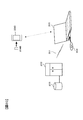
図1は、一実施の形態による電子機器(例えば、カメラ1)の構成を例示するブロック図である。図1において、カメラ1は、撮像光学系31と、撮像部32と、画像処理部33と、ワークメモリ34と、制御部35と、液晶モニタ36と、操作部材37と、不揮発性メモリ38と、記録部39と、発光装置40とを有する。 <Explanation of camera>
FIG. 1 is a block diagram illustrating the configuration of an electronic device (for example, camera 1) according to an embodiment. 1, thecamera 1 includes an imaging optical system 31, an imaging unit 32, an image processing unit 33, a work memory 34, a control unit 35, a liquid crystal monitor 36, an operation member 37, and a nonvolatile memory 38. And a recording unit 39 and a light emitting device 40.
図1は、一実施の形態による電子機器(例えば、カメラ1)の構成を例示するブロック図である。図1において、カメラ1は、撮像光学系31と、撮像部32と、画像処理部33と、ワークメモリ34と、制御部35と、液晶モニタ36と、操作部材37と、不揮発性メモリ38と、記録部39と、発光装置40とを有する。 <Explanation of camera>
FIG. 1 is a block diagram illustrating the configuration of an electronic device (for example, camera 1) according to an embodiment. 1, the
撮像光学系31は、被写界からの光束を撮像部32へ導く。撮像部32は、撮像素子100および駆動部32aを含み、撮像光学系31によって結像された被写体の像を光電変換する。撮像部32は、撮像素子100における撮像面の全域において同じ条件で撮像したり、撮像素子100における撮像面の領域ごとに異なる条件で撮像したりすることができる。撮像部32の詳細については後述する。駆動部32aは、撮像素子100に蓄積制御を行わせるために必要な駆動信号を生成する。撮像部32に対する電荷蓄積時間などの撮像指示は、制御部35から駆動部32aへ送信される。
The imaging optical system 31 guides the light flux from the object scene to the imaging unit 32. The imaging unit 32 includes an imaging device 100 and a driving unit 32a, and photoelectrically converts an image of a subject formed by the imaging optical system 31. The imaging unit 32 can capture an image on the entire imaging surface of the imaging element 100 under the same conditions, or can capture an image on different conditions for each area of the imaging surface of the imaging element 100. Details of the imaging unit 32 will be described later. The drive unit 32a generates a drive signal necessary for causing the image sensor 100 to perform accumulation control. An imaging instruction such as a charge accumulation time for the imaging unit 32 is transmitted from the control unit 35 to the driving unit 32a.
画像処理部33は、ワークメモリ34と協働して撮像部32で撮像された画像データに対する画像処理を行う。画像処理には、例えば、輪郭強調処理、ガンマ補正、ホワイトバランス調整、表示輝度調整、彩度調整等が含まれる。画像処理部33は、後述するように、画像の全域に対して同じパラメータ等を適用して画像処理をしたり、画像の領域ごとに異なるパラメータ等を適用して画像処理をしたりすることができる。
The image processing unit 33 performs image processing on the image data captured by the imaging unit 32 in cooperation with the work memory 34. The image processing includes, for example, contour enhancement processing, gamma correction, white balance adjustment, display luminance adjustment, saturation adjustment, and the like. As will be described later, the image processing unit 33 may perform image processing by applying the same parameter or the like to the entire area of the image, or may perform image processing by applying a different parameter or the like for each region of the image. it can.
ワークメモリ34は、画像処理前や後の画像データなどが一時的に記録されるメモリである。制御部35は、例えばCPUによって構成され、カメラ1による全体の動作を制御する。例えば、撮像部32で取得された画像信号に基づいて所定の露出演算を行い、適正露出に必要な撮像素子100の電荷蓄積時間(露光時間)、撮像光学系31の絞り値、ISO感度等の露出条件を決定して駆動部32aへ指示する。また、カメラ1に設定されている撮像シーンモードや、検出した被写体要素の種類に応じて、彩度、コントラスト、シャープネス等を調整する画像処理条件を決定して画像処理部33へ指示する。被写体要素の検出については後述する。さらにまた、発光装置40の発光を許可する設定が行われている場合には、適正露出に必要な発光装置40の発光量を決定して発光装置40へ指示する。
The work memory 34 is a memory in which image data before and after image processing is temporarily recorded. The control unit 35 is configured by a CPU, for example, and controls the overall operation of the camera 1. For example, a predetermined exposure calculation is performed based on the image signal acquired by the imaging unit 32, and the charge accumulation time (exposure time) of the image sensor 100 necessary for proper exposure, the aperture value of the imaging optical system 31, ISO sensitivity, and the like. The exposure condition is determined and an instruction is given to the drive unit 32a. In addition, image processing conditions for adjusting saturation, contrast, sharpness, and the like are determined and instructed to the image processing unit 33 according to the imaging scene mode set in the camera 1 and the type of the detected subject element. The detection of the subject element will be described later. Furthermore, when the setting for permitting the light emission of the light emitting device 40 is performed, the light emission amount of the light emitting device 40 necessary for proper exposure is determined and the light emitting device 40 is instructed.
制御部35には、物体検出部35aと、領域区分け部35bと、設定部35cと、撮像条件設定部35dと、撮像制御部35eと、AF演算部35fと、表示制御部35gとが含まれる。これらは、制御部35が不揮発性メモリ38に格納されているプログラムを実行することにより、ソフトウェア的に実現されるが、これらをASIC等により構成しても構わない。
The control unit 35 includes an object detection unit 35a, an area segmentation unit 35b, a setting unit 35c, an imaging condition setting unit 35d, an imaging control unit 35e, an AF calculation unit 35f, and a display control unit 35g. . These are realized by software by the control unit 35 executing a program stored in the nonvolatile memory 38, but these may be configured by an ASIC or the like.
物体検出部35aは、公知の物体認識処理を行うことにより、撮像部32によって取得された画像から、人物(人物の顔)、犬、猫などの動物(動物の顔)、植物、自転車、自動車、電車などの乗物、建造物、静止物、山、雲などの風景、あらかじめ定められた特定の物体などの、被写体要素を検出する。
The object detection unit 35a performs a known object recognition process, and from the image acquired by the imaging unit 32, an animal (animal face) such as a person (person's face), a dog, or a cat, a plant, a bicycle, an automobile , Detecting a subject element such as a vehicle such as a train, a building, a stationary object, a landscape such as a mountain or a cloud, or a predetermined specific object.
領域区分け部35bは、撮像部32による撮像画面を、上述のように検出した被写体要素を含む複数の領域に分割(区分け)する。設定部35cは、領域区分け部35bによって区分けされた複数の領域に序列をつける。序列の付け方については後述する。
The area dividing unit 35b divides (divides) the imaging screen by the imaging unit 32 into a plurality of areas including the subject element detected as described above. The setting unit 35c ranks the plurality of regions divided by the region dividing unit 35b. The ordering method will be described later.
撮像条件設定部35dは、領域区分け部35bによって区分けされた複数の領域に対して撮像条件を設定する。撮像条件は、上記露出条件(電荷蓄積時間、ゲイン、ISO感度、フレームレート等)と、上記画像処理条件(例えば、ホワイトバランス調整用パラメータ、ガンマ補正カーブ、表示輝度調整パラメータ、彩度調整パラメータ等)とを含む。なお、撮像条件は、複数の領域の全てに同じ撮像条件を設定することも、複数の領域間で異なる撮像条件を設定することも可能である。
The imaging condition setting unit 35d sets imaging conditions for a plurality of areas divided by the area dividing unit 35b. Imaging conditions include the exposure conditions (charge accumulation time, gain, ISO sensitivity, frame rate, etc.) and the image processing conditions (for example, white balance adjustment parameters, gamma correction curves, display brightness adjustment parameters, saturation adjustment parameters, etc.) ). As the imaging conditions, the same imaging conditions can be set for all of the plurality of areas, or different imaging conditions can be set for the plurality of areas.
撮像制御部35eは、撮像条件設定部35dによって上記領域ごとに設定された撮像条件を適用して撮像部32(撮像素子100)および画像処理部33を制御する。これにより、撮像部32に対しては、領域区分け部35bによって区分けされた複数の領域ごとに異なる露出条件で撮像を行わせることが可能であり、画像処理部33に対しては、領域区分け部35bによって区分けされた複数の領域ごとに異なる画像処理条件で画像処理を行わせることが可能である。
The imaging control unit 35e controls the imaging unit 32 (imaging device 100) and the image processing unit 33 by applying the imaging conditions set for each region by the imaging condition setting unit 35d. Thereby, it is possible to cause the imaging unit 32 to perform imaging under different exposure conditions for each of the plurality of regions divided by the region dividing unit 35b. For the image processing unit 33, the region dividing unit It is possible to perform image processing under different image processing conditions for each of the plurality of regions divided by 35b.
AF演算部35fは、撮像画面の所定の位置(フォーカスポイントと呼ぶ)で、対応する被写体に対してフォーカスを合わせる自動焦点調節(オートフォーカス:AF)演算を行う。AF演算部35fは、AF演算結果に基づいて、撮像光学系31のフォーカスレンズを合焦位置へ移動させるための駆動信号を送る。
なお、AF方式は、コントラスト検出方式でも、位相差検出方式でも構わない。 TheAF calculation unit 35f performs automatic focus adjustment (autofocus: AF) calculation for focusing on a corresponding subject at a predetermined position (called a focus point) on the imaging screen. The AF calculation unit 35f sends a drive signal for moving the focus lens of the imaging optical system 31 to the in-focus position based on the AF calculation result.
The AF method may be a contrast detection method or a phase difference detection method.
なお、AF方式は、コントラスト検出方式でも、位相差検出方式でも構わない。 The
The AF method may be a contrast detection method or a phase difference detection method.
表示制御部35gは、液晶モニタ36に表示させる画像の表示を制御する。表示制御部35gは、例えば、液晶モニタ36の表示面に一つの画像を表示させたり、液晶モニタ36の表示面に複数の画像を並べて表示させたりする。また、表示制御部35gは、ユーザーの操作に応じて、液晶モニタ36の表示面に表示中の画像をスクロール表示させる。
The display control unit 35g controls display of an image to be displayed on the liquid crystal monitor 36. The display control unit 35g displays, for example, one image on the display surface of the liquid crystal monitor 36, or displays a plurality of images side by side on the display surface of the liquid crystal monitor 36. Further, the display control unit 35g scrolls and displays the image being displayed on the display surface of the liquid crystal monitor 36 in accordance with a user operation.
液晶モニタ36は、画像処理部33によって画像処理された画像や、記録部39によって読み出された画像を再生表示する。液晶モニタ36は、操作メニュー画面や、撮像条件を設定するための設定画面等の表示も行う。
The liquid crystal monitor 36 reproduces and displays the image processed by the image processing unit 33 and the image read out by the recording unit 39. The liquid crystal monitor 36 also displays an operation menu screen, a setting screen for setting imaging conditions, and the like.
操作部材37は、レリーズボタンやメニューボタン等の種々の操作部材によって構成される。操作部材37は、各操作に対応する操作信号を制御部35へ送出する。操作部材37には、液晶モニタ36の表示面に設けられたタッチ操作部材も含まれる。
The operation member 37 is composed of various operation members such as a release button and a menu button. The operation member 37 sends an operation signal corresponding to each operation to the control unit 35. The operation member 37 includes a touch operation member provided on the display surface of the liquid crystal monitor 36.
不揮発性メモリ38は、制御部35が実行するプログラム等を記録する。記録部39は、制御部35からの指示に応じて、不図示のメモリカードなどで構成される記録媒体に画像データなどを記録する。また、記録部39は、制御部35からの指示に応じて記録媒体に記録されている画像データを読み出す。
The non-volatile memory 38 records a program executed by the control unit 35. In response to an instruction from the control unit 35, the recording unit 39 records image data or the like on a recording medium including a memory card (not shown). The recording unit 39 reads image data recorded on the recording medium in response to an instruction from the control unit 35.
発光装置40は被写体を照明する撮影補助光源である。発光装置40は、例えば発光許可設定されている場合において、制御部35からの発光指示に応じて制御部35から指示された光量で発光する。
The light emitting device 40 is a photographing auxiliary light source that illuminates the subject. For example, when the light emission permission is set, the light emitting device 40 emits light with the light amount instructed from the control unit 35 in response to the light emission instruction from the control unit 35.
<積層型撮像素子の説明>
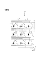
上述したカメラ1に備わる積層型撮像素子100について説明する。なお、この積層型撮像素子100は、本願出願人が先に出願し公開された国際公開WO13/164915号に記載されているものである。図2は、積層型撮像素子100の断面図である。撮像素子100は、入射光に対応した画素信号を出力する裏面照射型撮像チップ113と、画素信号を処理する信号処理チップ111と、画素信号を記録するメモリチップ112とを備える。これら撮像チップ113、信号処理チップ111およびメモリチップ112は積層されており、Cu等の導電性を有するバンプ109により互いに電気的に接続される。 <Description of Laminated Image Sensor>
Thelaminated image sensor 100 provided in the camera 1 described above will be described. The multilayer image sensor 100 is described in International Publication No. WO13 / 164915 previously filed and published by the applicant of the present application. FIG. 2 is a cross-sectional view of the multilayer image sensor 100. The imaging device 100 includes a backside illumination type imaging chip 113 that outputs a pixel signal corresponding to incident light, a signal processing chip 111 that processes the pixel signal, and a memory chip 112 that records the pixel signal. The imaging chip 113, the signal processing chip 111, and the memory chip 112 are stacked, and are electrically connected to each other by a conductive bump 109 such as Cu.
上述したカメラ1に備わる積層型撮像素子100について説明する。なお、この積層型撮像素子100は、本願出願人が先に出願し公開された国際公開WO13/164915号に記載されているものである。図2は、積層型撮像素子100の断面図である。撮像素子100は、入射光に対応した画素信号を出力する裏面照射型撮像チップ113と、画素信号を処理する信号処理チップ111と、画素信号を記録するメモリチップ112とを備える。これら撮像チップ113、信号処理チップ111およびメモリチップ112は積層されており、Cu等の導電性を有するバンプ109により互いに電気的に接続される。 <Description of Laminated Image Sensor>
The
なお、図示するように、入射光は主に白抜き矢印で示すZ軸プラス方向へ向かって入射する。本実施形態においては、撮像チップ113において、入射光が入射する側の面を裏面(撮像面)と称する。また、座標軸に示すように、Z軸に直交する紙面左方向をX軸プラス方向、Z軸およびX軸に直交する紙面手前方向をY軸プラス方向とする。以降のいくつかの図においては、図2の座標軸を基準として、それぞれの図の向きがわかるように座標軸を表示する。
As shown in the figure, incident light is incident mainly in the positive direction of the Z axis indicated by the white arrow. In the present embodiment, in the imaging chip 113, the surface on the side where incident light enters is referred to as a back surface (imaging surface). Further, as shown in the coordinate axes, the left direction of the paper orthogonal to the Z axis is the X axis plus direction, and the front side of the paper orthogonal to the Z axis and the X axis is the Y axis plus direction. In the following several figures, the coordinate axes are displayed so that the orientation of each figure can be understood with reference to the coordinate axes in FIG.
撮像チップ113の一例は、裏面照射型のMOSイメージセンサである。PD層106は、配線層108の裏面側に配されている。PD層106は、二次元的に配され、入射光に応じた電荷を蓄積する複数のPD(フォトダイオード)104、および、PD104に対応して設けられたトランジスタ105を有する。
An example of the imaging chip 113 is a back-illuminated MOS image sensor. The PD layer 106 is disposed on the back side of the wiring layer 108. The PD layer 106 includes a plurality of PDs (photodiodes) 104 that are two-dimensionally arranged and store charges corresponding to incident light, and transistors 105 that are provided corresponding to the PDs 104.
PD層106における入射光の入射側にはパッシベーション膜103を介してカラーフィルタ102が設けられる。カラーフィルタ102は、互いに異なる波長領域を透過する複数の種類を有しており、PD104のそれぞれに対応して特定の配列を有している。カラーフィルタ102の配列については後述する。カラーフィルタ102、PD104およびトランジスタ105の組が、一つの画素を形成する。
A color filter 102 is provided on the incident light incident side of the PD layer 106 via a passivation film 103. The color filter 102 has a plurality of types that transmit different wavelength regions, and has a specific arrangement corresponding to each of the PDs 104. The arrangement of the color filter 102 will be described later. A set of the color filter 102, the PD 104, and the transistor 105 forms one pixel.
カラーフィルタ102における入射光の入射側には、それぞれの画素に対応して、マイクロレンズ101が設けられる。マイクロレンズ101は、対応するPD104へ向けて入射光を集光する。
A microlens 101 is provided on the incident light incident side of the color filter 102 corresponding to each pixel. The microlens 101 condenses incident light toward the corresponding PD 104.
配線層108は、PD層106からの画素信号を信号処理チップ111に伝送する配線107を有する。配線107は多層であってもよく、また、受動素子および能動素子が設けられてもよい。
The wiring layer 108 includes a wiring 107 that transmits a pixel signal from the PD layer 106 to the signal processing chip 111. The wiring 107 may be multilayer, and a passive element and an active element may be provided.
配線層108の表面には複数のバンプ109が配される。当該複数のバンプ109が信号処理チップ111の対向する面に設けられた複数のバンプ109と位置合わせされて、撮像チップ113と信号処理チップ111とが加圧等されることにより、位置合わせされたバンプ109同士が接合されて、電気的に接続される。
A plurality of bumps 109 are arranged on the surface of the wiring layer 108. The plurality of bumps 109 are aligned with the plurality of bumps 109 provided on the opposing surfaces of the signal processing chip 111, and the imaging chip 113 and the signal processing chip 111 are pressed and aligned. The bumps 109 are joined and electrically connected.
同様に、信号処理チップ111およびメモリチップ112の互いに対向する面には、複数のバンプ109が配される。これらのバンプ109が互いに位置合わせされて、信号処理チップ111とメモリチップ112とが加圧等されることにより、位置合わせされたバンプ109同士が接合されて、電気的に接続される。
Similarly, a plurality of bumps 109 are arranged on the mutually facing surfaces of the signal processing chip 111 and the memory chip 112. The bumps 109 are aligned with each other, and the signal processing chip 111 and the memory chip 112 are pressurized, so that the aligned bumps 109 are joined and electrically connected.
なお、バンプ109間の接合には、固相拡散によるCuバンプ接合に限らず、はんだ溶融によるマイクロバンプ結合を採用してもよい。また、バンプ109は、例えば後述する一つのブロックに対して一つ程度設ければよい。したがって、バンプ109の大きさは、PD104のピッチよりも大きくてもよい。また、画素が配列された画素領域以外の周辺領域において、画素領域に対応するバンプ109よりも大きなバンプを併せて設けてもよい。
Note that the bonding between the bumps 109 is not limited to Cu bump bonding by solid phase diffusion, and micro bump bonding by solder melting may be employed. Further, for example, about one bump 109 may be provided for one block described later. Therefore, the size of the bump 109 may be larger than the pitch of the PD 104. Further, a bump larger than the bump 109 corresponding to the pixel region may be provided in a peripheral region other than the pixel region where the pixels are arranged.
信号処理チップ111は、表裏面にそれぞれ設けられた回路を互いに接続するTSV(シリコン貫通電極)110を有する。TSV110は、周辺領域に設けられることが好ましい。また、TSV110は、撮像チップ113の周辺領域、メモリチップ112にも設けられてよい。
The signal processing chip 111 has TSVs (silicon through electrodes) 110 that connect circuits provided on the front and back surfaces to each other. The TSV 110 is preferably provided in the peripheral area. The TSV 110 may also be provided in the peripheral area of the imaging chip 113 and the memory chip 112.
図3は、撮像チップ113の画素配列と単位領域131を説明する図である。特に、撮像チップ113を裏面(撮像面)側から観察した様子を示す。画素領域には例えば2000万個以上もの画素がマトリックス状に配列されている。図3の例では、隣接する4画素×4画素の16画素が一つの単位領域131を形成する。図の格子線は、隣接する画素がグループ化されて単位領域131を形成する概念を示す。単位領域131を形成する画素の数は、これに限られず1000個程度、例えば32画素×64画素でもよいし、それ以上でもそれ以下でもよい。
FIG. 3 is a diagram for explaining the pixel array and the unit area 131 of the imaging chip 113. In particular, a state where the imaging chip 113 is observed from the back surface (imaging surface) side is shown. For example, 20 million or more pixels are arranged in a matrix in the pixel region. In the example of FIG. 3, adjacent 16 pixels of 4 pixels × 4 pixels form one unit region 131. The grid lines in the figure indicate the concept that adjacent pixels are grouped to form a unit region 131. The number of pixels forming the unit region 131 is not limited to this, and may be about 1000, for example, 32 pixels × 64 pixels, or more or less.
画素領域の部分拡大図に示すように、図3の単位領域131は、緑色画素Gb、Gr、青色画素Bおよび赤色画素Rの4画素から成るいわゆるベイヤー配列を、上下左右に4つ内包する。緑色画素Gb、Grは、カラーフィルタ102として緑色フィルタを有する画素であり、入射光のうち緑色波長帯の光を受光する。同様に、青色画素Bは、カラーフィルタ102として青色フィルタを有する画素であって青色波長帯の光を受光し、赤色画素Rは、カラーフィルタ102として赤色フィルタを有する画素であって赤色波長帯の光を受光する。
As shown in the partial enlarged view of the pixel region, the unit region 131 in FIG. 3 includes four so-called Bayer arrays, which are composed of four pixels of green pixels Gb, Gr, blue pixels B, and red pixels R, vertically and horizontally. The green pixels Gb and Gr are pixels having a green filter as the color filter 102, and receive light in the green wavelength band of incident light. Similarly, the blue pixel B is a pixel having a blue filter as the color filter 102 and receives light in the blue wavelength band, and the red pixel R is a pixel having a red filter as the color filter 102 and having a red wavelength band. Receives light.
本実施形態において、1ブロックにつき単位領域131を少なくとも一つ含むように複数のブロックが定義され、各ブロックはそれぞれ異なる制御パラメータで各ブロックに含まれる画素を制御できる。つまり、あるブロックに含まれる画素群と、別のブロックに含まれる画素群とで、撮像条件が異なる撮像信号を取得できる。制御パラメータの例は、フレームレート、ゲイン、間引き率、画素信号を加算する加算行数または加算列数、電荷の蓄積時間または蓄積回数、デジタル化のビット数(語長)等である。撮像素子100は、行方向(撮像チップ113のX軸方向)の間引きのみでなく、列方向(撮像チップ113のY軸方向)の間引きも自在に行える。さらに、制御パラメータは、画素からの画像信号取得後の画像処理におけるパラメータであってもよい。
In this embodiment, a plurality of blocks are defined so as to include at least one unit region 131 per block, and each block can control pixels included in each block with different control parameters. That is, it is possible to acquire imaging signals having different imaging conditions between a pixel group included in a certain block and a pixel group included in another block. Examples of the control parameters include a frame rate, a gain, a thinning rate, the number of addition rows or addition columns to which pixel signals are added, a charge accumulation time or accumulation count, a digitization bit number (word length), and the like. The imaging element 100 can freely perform not only thinning in the row direction (X-axis direction of the imaging chip 113) but also thinning in the column direction (Y-axis direction of the imaging chip 113). Furthermore, the control parameter may be a parameter in image processing after obtaining an image signal from a pixel.
図4は、単位領域131における回路を説明する図である。図4の例では、隣接する3画素×3画素の9画素により一つの単位領域131を形成する。なお、上述したように単位領域131に含まれる画素の数はこれに限られず、これ以下でもこれ以上でもよい。単位領域131の二次元的な位置を符号A~Iにより示す。
FIG. 4 is a diagram for explaining a circuit in the unit region 131. In the example of FIG. 4, one unit region 131 is formed by 9 pixels of 3 pixels × 3 pixels adjacent to each other. As described above, the number of pixels included in the unit region 131 is not limited to this, and may be less than this or more. The two-dimensional position of the unit area 131 is indicated by symbols A to I.
単位領域131に含まれる画素のリセットトランジスタは、画素ごとに個別にオンオフ可能に構成される。図4において、画素Aのリセットトランジスタをオンオフするリセット配線300が設けられており、画素Bのリセットトランジスタをオンオフするリセット配線310が、上記リセット配線300とは別個に設けられている。同様に、画素Cのリセットトランジスタをオンオフするリセット配線320が、上記リセット配線300、310とは別個に設けられている。他の画素Dから画素Iに対しても、それぞれのリセットトランジスタをオンオフするための専用のリセット配線が設けられている。
The reset transistors of the pixels included in the unit region 131 are configured to be turned on and off individually for each pixel. In FIG. 4, a reset wiring 300 for turning on / off the reset transistor of the pixel A is provided, and a reset wiring 310 for turning on / off the reset transistor of the pixel B is provided separately from the reset wiring 300. Similarly, a reset line 320 for turning on and off the reset transistor of the pixel C is provided separately from the reset lines 300 and 310. Also for the other pixels D to I, dedicated reset wirings for turning on and off the respective reset transistors are provided.
単位領域131に含まれる画素の転送トランジスタについても、画素ごとに個別にオンオフ可能に構成される。図4において、画素Aの転送トランジスタをオンオフする転送配線302、画素Bの転送トランジスタをオンオフする転送配線312、画素Cの転送トランジスタをオンオフする転送配線322が、別個に設けられている。他の画素Dから画素Iに対しても、それぞれの転送トランジスタをオンオフするための専用の転送配線が設けられている。
The transfer transistors of the pixels included in the unit region 131 are also configured to be turned on and off individually for each pixel. In FIG. 4, a transfer wiring 302 for turning on / off the transfer transistor of the pixel A, a transfer wiring 312 for turning on / off the transfer transistor of the pixel B, and a transfer wiring 322 for turning on / off the transfer transistor of the pixel C are separately provided. Also for the other pixels D to I, dedicated transfer wirings for turning on / off the respective transfer transistors are provided.
さらに、単位領域131に含まれる画素の選択トランジスタについても、画素ごとに個別にオンオフ可能に構成される。図4において、画素Aの選択トランジスタをオンオフする選択配線306、画素Bの選択トランジスタをオンオフする選択配線316、画素Cの選択トランジスタをオンオフする選択配線326が、別個に設けられている。他の画素Dから画素Iに対しても、それぞれの選択トランジスタをオンオフするための専用の選択配線が設けられている。
Furthermore, the selection transistors of the pixels included in the unit region 131 are also configured to be turned on and off individually for each pixel. In FIG. 4, a selection wiring 306 for turning on / off the selection transistor of the pixel A, a selection wiring 316 for turning on / off the selection transistor of the pixel B, and a selection wiring 326 for turning on / off the selection transistor of the pixel C are separately provided. Also for the other pixels D to I, a dedicated selection wiring for turning on and off each selection transistor is provided.
なお、電源配線304は、単位領域131に含まれる画素Aから画素Iで共通に接続されている。同様に、出力配線308は、単位領域131に含まれる画素Aから画素Iで共通に接続されている。また、電源配線304は複数の単位領域間で共通に接続されるが、出力配線308は単位領域131ごとに個別に設けられる。負荷電流源309は、出力配線308へ電流を供給する。負荷電流源309は、撮像チップ113側に設けられてもよいし、信号処理チップ111側に設けられてもよい。
Note that the power supply wiring 304 is commonly connected from the pixel A to the pixel I included in the unit region 131. Similarly, the output wiring 308 is commonly connected from the pixel A to the pixel I included in the unit region 131. Further, the power supply wiring 304 is commonly connected between a plurality of unit regions, but the output wiring 308 is provided for each unit region 131 individually. The load current source 309 supplies current to the output wiring 308. The load current source 309 may be provided on the imaging chip 113 side or may be provided on the signal processing chip 111 side.
単位領域131のリセットトランジスタおよび転送トランジスタを個別にオンオフすることにより、単位領域131に含まれる画素Aから画素Iに対して、電荷の蓄積開始時間、蓄積終了時間、転送タイミングを含む電荷蓄積を制御することができる。また、単位領域131の選択トランジスタを個別にオンオフすることにより、各画素Aから画素Iの画素信号を共通の出力配線308を介して出力することができる。
By individually turning on and off the reset transistor and the transfer transistor in the unit region 131, the charge accumulation including the charge accumulation start time, the accumulation end time, and the transfer timing is controlled from the pixel A to the pixel I included in the unit region 131. can do. In addition, by individually turning on and off the selection transistors in the unit region 131, the pixel signals of the pixels I from each pixel A can be output via the common output wiring 308.
ここで、単位領域131に含まれる画素Aから画素Iについて、行および列に対して規則的な順序で電荷蓄積を制御する、いわゆるローリングシャッタ方式が公知である。ローリングシャッタ方式により行ごとに画素を選択してから列を指定すると、図4の例では「ABCDEFGHI」の順序で画素信号が出力される。
Here, a so-called rolling shutter system is known in which charge accumulation is controlled in a regular order with respect to rows and columns for pixels A to I included in the unit region 131. When a column is designated after selecting a pixel for each row by the rolling shutter method, pixel signals are output in the order of “ABCDEFGHI” in the example of FIG.
このように単位領域131を基準として回路を構成することにより、単位領域131ごとに電荷蓄積時間を制御することができる。換言すると、単位領域131間で異なったフレームレートによる画素信号をそれぞれ出力させることができる。また、撮像チップ113において一部のブロックに含まれる単位領域131に電荷蓄積(撮像)を行わせる間に他のブロックに含まれる単位領域131を休ませることにより、撮像チップ113の所定のブロックでのみ撮像を行わせて、その画素信号を出力させることができる。さらに、フレーム間で電荷蓄積(撮像)を行わせるブロック(蓄積制御の対象ブロック)を切り替えて、撮像チップ113の異なるブロックで逐次撮像を行わせて、画素信号を出力させることもできる。
Thus, by configuring the circuit with the unit region 131 as a reference, the charge accumulation time can be controlled for each unit region 131. In other words, it is possible to output pixel signals with different frame rates between the unit areas 131. Further, in the imaging chip 113, the unit area 131 included in another block is rested while the unit areas 131 included in some blocks perform charge accumulation (imaging). Only the image can be taken and the pixel signal can be output. Furthermore, it is also possible to switch the block (accumulation control target block) where charge accumulation (imaging) is performed between frames and sequentially perform imaging with different blocks of the imaging chip 113 to output pixel signals.
図5は、図4に例示した回路に対応する撮像素子100の機能的構成を示すブロック図である。アナログのマルチプレクサ411は、単位領域131を形成する9個のPD104を順番に選択して、それぞれの画素信号を当該単位領域131に対応して設けられた出力配線308へ出力させる。マルチプレクサ411は、PD104と共に、撮像チップ113に形成される。
FIG. 5 is a block diagram illustrating a functional configuration of the image sensor 100 corresponding to the circuit illustrated in FIG. The analog multiplexer 411 sequentially selects the nine PDs 104 forming the unit region 131 and outputs each pixel signal to the output wiring 308 provided corresponding to the unit region 131. The multiplexer 411 is formed on the imaging chip 113 together with the PD 104.
マルチプレクサ411を介して出力された画素信号は、信号処理チップ111に形成された、相関二重サンプリング(CDS)・アナログ/デジタル(A/D)変換を行う信号処理回路412により、CDSおよびA/D変換が行われる。A/D変換された画素信号は、デマルチプレクサ413に引き渡され、それぞれの画素に対応する画素メモリ414に格納される。デマルチプレクサ413および画素メモリ414は、メモリチップ112に形成される。
The pixel signal output via the multiplexer 411 is supplied to the signal processing chip 111 by a signal processing circuit 412 that performs correlated double sampling (CDS) / analog / digital (A / D) conversion. D conversion is performed. The A / D converted pixel signal is transferred to the demultiplexer 413 and stored in the pixel memory 414 corresponding to each pixel. The demultiplexer 413 and the pixel memory 414 are formed in the memory chip 112.
演算回路415は、画素メモリ414に格納された画素信号を処理して後段の画像処理部に引き渡す。演算回路415は、信号処理チップ111に設けられてもよいし、メモリチップ112に設けられてもよい。なお、図5では一つの単位領域131の分の接続を示すが、実際にはこれらが単位領域131ごとに存在して、並列で動作する。ただし、演算回路415は単位領域131ごとに存在しなくてもよく、例えば、一つの演算回路415がそれぞれの単位領域131に対応する画素メモリ414の値を順に参照しながらシーケンシャルに処理してもよい。
The arithmetic circuit 415 processes the pixel signal stored in the pixel memory 414 and passes it to the subsequent image processing unit. The arithmetic circuit 415 may be provided in the signal processing chip 111 or may be provided in the memory chip 112. Note that FIG. 5 shows connections for one unit region 131, but actually these exist for each unit region 131 and operate in parallel. However, the arithmetic circuit 415 does not have to exist for each unit region 131. For example, one arithmetic circuit 415 may perform sequential processing while sequentially referring to the values of the pixel memory 414 corresponding to each unit region 131. Good.
上記の通り、単位領域131のそれぞれに対応して出力配線308が設けられている。撮像素子100は撮像チップ113、信号処理チップ111およびメモリチップ112を積層しているので、これら出力配線308にバンプ109を用いたチップ間の電気的接続を用いることにより、各チップを面方向に大きくすることなく配線を引き回すことができる。
As described above, the output wiring 308 is provided corresponding to each of the unit areas 131. Since the image pickup device 100 includes the image pickup chip 113, the signal processing chip 111, and the memory chip 112, each chip is arranged in the plane direction by using an electrical connection between the chips using the bump 109 for the output wiring 308. Wiring can be routed without increasing the size.
<領域ごとの撮像条件設定>
本実施形態では、撮像素子100(撮像チップ113)における複数のブロックごとに撮像条件を設定可能に構成する。制御部35は、領域区分け部35bによって区分けされた領域を上記ブロックに対応させて、領域ごとに設定した撮像条件で撮像を行わせる。 <Imaging condition setting for each area>
In the present embodiment, an imaging condition can be set for each of a plurality of blocks in the imaging device 100 (imaging chip 113). Thecontrol unit 35 causes the region divided by the region dividing unit 35b to correspond to the block, and performs imaging under the imaging condition set for each region.
本実施形態では、撮像素子100(撮像チップ113)における複数のブロックごとに撮像条件を設定可能に構成する。制御部35は、領域区分け部35bによって区分けされた領域を上記ブロックに対応させて、領域ごとに設定した撮像条件で撮像を行わせる。 <Imaging condition setting for each area>
In the present embodiment, an imaging condition can be set for each of a plurality of blocks in the imaging device 100 (imaging chip 113). The
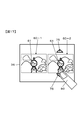
ユーザーは、例えば、液晶モニタ36の表示面に表示されるライブビュー画像を確認しながら、所望の領域に対して撮像条件を設定する。ライブビュー画像は、所定のフレームレート(例えば60fps)で繰り返し撮像するモニタ用画像のことをいう。
The user sets imaging conditions for a desired area while confirming a live view image displayed on the display surface of the liquid crystal monitor 36, for example. The live view image refers to a monitor image that is repeatedly imaged at a predetermined frame rate (for example, 60 fps).
ユーザーが、ある領域に対して撮像条件を設定(変更)すると、制御部35は、ライブビュー画像のうちのその領域に対して画像処理部33によって画像処理を行わせる。ここで行う画像処理は、撮像条件の変更による効果を確認するための画像処理である。例えば、輝度を高める変更がなされた場合は、液晶モニタ36へ表示する表示輝度を高める画像処理を行う。また、例えば発光装置40を発光させる変更がなされた場合は、所定の被写体要素(例えば人物)について、液晶モニタ36へ表示する表示輝度を高める画像処理を行う。さらにまた、例えば、彩度を高める変更がなされた場合は、液晶モニタ36へ表示する所定の被写体要素(例えば花)について、彩度を高める画像処理を行う。
このように、ユーザーは、撮像条件の変更による効果を本撮像の前に、画像処理されたライブビュー画像で確認することができる。このような領域ごとの撮像条件設定について、以下に詳しく説明する。
なお、ある領域に対して操作された撮像条件の変更による効果を確認するために画像処理を行い液晶モニタ36へ表示する方法に限らず、ある領域に対して操作された撮像条件の変更をその領域に対応する撮像素子へ反映し、設定(変更)された撮像条件のライブビュー画像を液晶モニタ36へ表示する方法を用いてもよい。 When the user sets (changes) the imaging condition for a certain area, thecontrol unit 35 causes the image processing unit 33 to perform image processing on that area of the live view image. The image processing performed here is image processing for confirming the effect of changing the imaging condition. For example, when a change to increase the luminance is made, image processing to increase the display luminance displayed on the liquid crystal monitor 36 is performed. For example, when the light emitting device 40 is changed to emit light, image processing for increasing the display luminance displayed on the liquid crystal monitor 36 is performed for a predetermined subject element (for example, a person). Furthermore, for example, when a change for increasing the saturation is made, image processing for increasing the saturation is performed on a predetermined subject element (for example, a flower) displayed on the liquid crystal monitor 36.
In this way, the user can confirm the effect of changing the imaging condition on the live view image that has been subjected to image processing before the actual imaging. The imaging condition setting for each region will be described in detail below.
In addition, not only the method of performing image processing and displaying on the liquid crystal monitor 36 to confirm the effect of the change of the imaging condition operated for a certain area, but also the change of the imaging condition operated for a certain area A method of displaying on the liquid crystal monitor 36 a live view image of the imaging condition set (changed) reflected on the imaging element corresponding to the region may be used.
このように、ユーザーは、撮像条件の変更による効果を本撮像の前に、画像処理されたライブビュー画像で確認することができる。このような領域ごとの撮像条件設定について、以下に詳しく説明する。
なお、ある領域に対して操作された撮像条件の変更による効果を確認するために画像処理を行い液晶モニタ36へ表示する方法に限らず、ある領域に対して操作された撮像条件の変更をその領域に対応する撮像素子へ反映し、設定(変更)された撮像条件のライブビュー画像を液晶モニタ36へ表示する方法を用いてもよい。 When the user sets (changes) the imaging condition for a certain area, the
In this way, the user can confirm the effect of changing the imaging condition on the live view image that has been subjected to image processing before the actual imaging. The imaging condition setting for each region will be described in detail below.
In addition, not only the method of performing image processing and displaying on the liquid crystal monitor 36 to confirm the effect of the change of the imaging condition operated for a certain area, but also the change of the imaging condition operated for a certain area A method of displaying on the liquid crystal monitor 36 a live view image of the imaging condition set (changed) reflected on the imaging element corresponding to the region may be used.
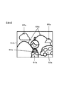
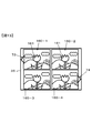
図6は、カメラ1の撮像素子100に結像される被写体の像を模式的に示す図である。カメラ1は、撮像指示が行われる前に、被写体像を光電変換してライブビュー画像を取得する。
FIG. 6 is a diagram schematically showing a subject image formed on the image sensor 100 of the camera 1. The camera 1 photoelectrically converts the subject image to obtain a live view image before an imaging instruction is given.
制御部35は、初めに、撮像チップ113の全域(すなわち撮像面の全域)に同じ撮像条件を設定する。撮像条件のうち露出条件は、被写体輝度の測光値に応じて適正露出となるように算出した露出条件、またはユーザーによって手動設定された露出条件に基づいて決定する。撮像条件のうち画像処理条件は、標準的な画質となるようにあらかじめ用意された画像処理条件に決定する。以降、このように決定した撮像条件を基準条件と呼ぶ。また、基準条件を適用して取得した画像を基準画像と呼ぶ。
The control unit 35 first sets the same imaging condition over the entire area of the imaging chip 113 (that is, the entire area of the imaging surface). Among the imaging conditions, the exposure condition is determined based on the exposure condition calculated to obtain an appropriate exposure according to the photometric value of the subject luminance or the exposure condition manually set by the user. Among the imaging conditions, the image processing condition is determined as an image processing condition prepared in advance so as to obtain a standard image quality. Hereinafter, the imaging condition determined in this way is referred to as a reference condition. An image acquired by applying the reference condition is called a reference image.
基準条件を決定する一例を説明する。制御部35は、操作部材37を構成する露出モード切替スイッチからの操作信号に応じて、「プログラムオート」モード、「シャッター速度優先オート」モード、「絞り優先オート」モード、および「マニュアル」モードのうち一つを選択する。そして、制御部35は、選択した露出モードに応じた所定の露出演算を行うことによって上記露出条件(電荷蓄積時間、ゲイン、ISO感度、フレームレート等)を算出する。
An example of determining the reference condition will be described. In response to an operation signal from an exposure mode changeover switch constituting the operation member 37, the control unit 35 performs a “program auto” mode, a “shutter speed priority auto” mode, an “aperture priority auto” mode, and a “manual” mode. Select one of them. The control unit 35 calculates the exposure conditions (charge accumulation time, gain, ISO sensitivity, frame rate, etc.) by performing a predetermined exposure calculation according to the selected exposure mode.
具体的には、「プログラムオート」モードの場合、制御部35は、例えば画面内の平均的な輝度が適正となるように絞り値、シャッター速度(電荷蓄積時間)、ゲイン等を決定する。「シャッター速度優先オート」モードの場合、制御部35は、ユーザーが設定するシャッター速度(電荷蓄積時間)を用いて、例えば画面内の平均的な輝度が適正となるように絞り値、ゲイン等を決定する。「絞り優先オート」モードの場合、制御部35は、ユーザーが設定する絞り値を用いて、例えば画面内の平均的な輝度が適正となるようにシャッター速度(電荷蓄積時間)、ゲイン等を決定する。「マニュアル」モードの場合、制御部35は、ユーザーが設定する絞り値およびシャッター速度(電荷蓄積時間)に基づいて、適正露出との偏差を演算する。
Specifically, in the “program auto” mode, the control unit 35 determines an aperture value, a shutter speed (charge accumulation time), a gain, and the like so that the average luminance in the screen is appropriate. In the “shutter speed priority auto” mode, the control unit 35 uses the shutter speed (charge accumulation time) set by the user, for example, to set an aperture value, a gain, and the like so that the average brightness in the screen is appropriate. decide. In the “aperture priority auto” mode, the control unit 35 determines a shutter speed (charge accumulation time), a gain, and the like so that the average brightness in the screen is appropriate, for example, using the aperture value set by the user. To do. In the “manual” mode, the control unit 35 calculates the deviation from the appropriate exposure based on the aperture value set by the user and the shutter speed (charge accumulation time).
図6において、撮像チップ113の撮像面に、人物61aと、自動車62aと、バッグ63aと、山64aと、雲65a、66aとを含む像が結像されている。人物61aは、バッグ63aを両手で抱えている。人物61aの右後方に、自動車62aが止まっている。
6, an image including a person 61a, an automobile 62a, a bag 63a, a mountain 64a, and clouds 65a and 66a is formed on the imaging surface of the imaging chip 113. The person 61a holds the bag 63a with both hands. The automobile 62a stops at the right rear of the person 61a.
<領域の区分け>
制御部35は、ライブビュー画像に基づき、以下のようにライブビュー画像として取得した画像を複数の領域に区分けする。先ず、物体検出部35aによってライブビュー画像から被写体要素を検出する。被写体要素の検出は、公知の被写体認識技術を用いる。図6の例では、物体検出部35aが、人物61aと、自動車62aと、バッグ63aと、山64aと、雲65aと、雲66aとを被写体要素として検出する。 <Division of area>
Based on the live view image, thecontrol unit 35 divides the image acquired as the live view image into a plurality of regions as follows. First, the subject element is detected from the live view image by the object detection unit 35a. The subject element is detected using a known subject recognition technique. In the example of FIG. 6, the object detection unit 35a detects a person 61a, a car 62a, a bag 63a, a mountain 64a, a cloud 65a, and a cloud 66a as subject elements.
制御部35は、ライブビュー画像に基づき、以下のようにライブビュー画像として取得した画像を複数の領域に区分けする。先ず、物体検出部35aによってライブビュー画像から被写体要素を検出する。被写体要素の検出は、公知の被写体認識技術を用いる。図6の例では、物体検出部35aが、人物61aと、自動車62aと、バッグ63aと、山64aと、雲65aと、雲66aとを被写体要素として検出する。 <Division of area>
Based on the live view image, the
次に、領域区分け部35bによって、ライブビュー画像として取得した画像を上記検出手段に基づき、被写体要素を含む領域に区分けする。本例では、人物61aを含む領域を第1領域61とし、自動車62aを含む領域を第2領域62とし、バッグ63aを含む領域を第3領域63とし、山64aを含む領域を第4領域64とし、雲65aを含む領域を第5領域65とし、雲66aを含む領域を第6領域66として説明する。
Next, an image acquired as a live view image is divided into regions including subject elements by the region dividing unit 35b based on the detection means. In this example, the area including the person 61a is the first area 61, the area including the car 62a is the second area 62, the area including the bag 63a is the third area 63, and the area including the mountain 64a is the fourth area 64. The region including the cloud 65a is referred to as a fifth region 65, and the region including the cloud 66a is referred to as a sixth region 66.
設定部35cによって、領域区分け部35bが区分けした複数の領域に対して序列をつける。設定部35cは、領域区分け部35bによって区分けされた領域のうち、次の(1)から(4)の領域を検出した場合、撮像条件を領域区分け部35bによって区分けされた他の領域よりも優先的に変更する領域として設定する。
(1)撮像シーンモードに応じた特定の被写体が検出された領域
特定の被写体は、設定されたカメラ1の撮像シーンモードによって異なる。例えば、カメラ1の撮像シーンモード設定がポートレートモードに設定されている場合に、設定部35cは、人物61aを含む第1領域61に対して、自動車62aを含む領域を第2領域62と、バッグ63aを含む領域を第3領域63と、山64aを含む領域を第4領域64と、雲65aを含む領域を第5領域65と、雲66aを含む領域を第6領域66よりも撮像条件を優先的に変更する領域として設定する。ポートレートモードの場合は、人物61aを含む第1領域61の撮像条件を設定(変更)する可能性が高いという考え方に基づく。 Thesetting unit 35c ranks the plurality of regions divided by the region dividing unit 35b. When the setting unit 35c detects the following regions (1) to (4) among the regions divided by the region dividing unit 35b, the setting unit 35c prioritizes the imaging condition over the other regions divided by the region dividing unit 35b. Set as an area to be changed automatically.
(1) Region in which a specific subject is detected according to the imaging scene mode The specific subject differs depending on the imaging scene mode of thecamera 1 that has been set. For example, when the imaging scene mode setting of the camera 1 is set to the portrait mode, the setting unit 35c sets the area including the automobile 62a as the second area 62 with respect to the first area 61 including the person 61a. The region including the bag 63 a is the third region 63, the region including the mountain 64 a is the fourth region 64, the region including the cloud 65 a is the fifth region 65, and the region including the cloud 66 a is the imaging condition than the sixth region 66. Is set as an area to be preferentially changed. In the case of the portrait mode, it is based on the idea that there is a high possibility of setting (changing) the imaging condition of the first area 61 including the person 61a.
(1)撮像シーンモードに応じた特定の被写体が検出された領域
特定の被写体は、設定されたカメラ1の撮像シーンモードによって異なる。例えば、カメラ1の撮像シーンモード設定がポートレートモードに設定されている場合に、設定部35cは、人物61aを含む第1領域61に対して、自動車62aを含む領域を第2領域62と、バッグ63aを含む領域を第3領域63と、山64aを含む領域を第4領域64と、雲65aを含む領域を第5領域65と、雲66aを含む領域を第6領域66よりも撮像条件を優先的に変更する領域として設定する。ポートレートモードの場合は、人物61aを含む第1領域61の撮像条件を設定(変更)する可能性が高いという考え方に基づく。 The
(1) Region in which a specific subject is detected according to the imaging scene mode The specific subject differs depending on the imaging scene mode of the
例えば、カメラ1の撮像シーンモード設定がクローズアップモードに設定されており、かつ、物体検出部35aにより被写体要素として花が検出されている場合において、設定部35cは、花を含む領域に対して、他の領域よりも撮像条件を優先的に変更する領域として設定する。クローズアップモードの場合は、花を含む領域の撮像条件を設定(変更)する可能性が高いという考え方に基づく。
For example, when the imaging scene mode setting of the camera 1 is set to the close-up mode and a flower is detected as a subject element by the object detection unit 35a, the setting unit 35c The imaging condition is set as a region that is changed with priority over other regions. In the case of the close-up mode, it is based on the idea that there is a high possibility of setting (changing) the imaging condition of the region including the flower.
例えば、カメラ1の撮像シーンモード設定が風景モードに設定されており、かつ、物体検出部35aにより被写体要素として山が検出されている場合において、設定部35cは、山を含む領域に対して、他の領域よりも撮像条件を優先的に変更する領域として設定する。風景モードの場合は、山を含む領域の撮像条件を設定(変更)する可能性が高いという考え方に基づく。
For example, when the imaging scene mode setting of the camera 1 is set to landscape mode and a mountain is detected as a subject element by the object detection unit 35a, the setting unit 35c It is set as an area where imaging conditions are changed with priority over other areas. In the case of the landscape mode, it is based on the idea that there is a high possibility of setting (changing) the imaging condition of the area including the mountain.
例えば、カメラ1の撮像シーンモード設定がビーチモードに設定されており、かつ、物体検出部35aにより被写体要素として海が検出されている場合において、設定部35cは、海を含む領域に対して、他の領域よりも撮像条件を優先的に変更する領域として設定する。ビーチモードの場合は、海を含む領域の撮像条件を設定(変更)する可能性が高いという考え方に基づく。
For example, when the imaging scene mode setting of the camera 1 is set to the beach mode and the sea is detected as the subject element by the object detection unit 35a, the setting unit 35c It is set as an area where imaging conditions are changed with priority over other areas. In the case of the beach mode, it is based on the idea that there is a high possibility of setting (changing) the imaging condition of the region including the sea.
例えば、カメラ1の撮像シーンモード設定が夕焼けモードに設定されており、かつ、物体検出部35aにより被写体要素として赤い空が検出されている場合において、設定部35cは、赤い空を含む領域に対して、他の領域よりも撮像条件を優先的に変更する領域として設定する。夕焼けモードの場合は、赤い空を含む領域の撮像条件を設定(変更)する可能性が高いという考え方に基づく。
For example, when the imaging scene mode setting of the camera 1 is set to the sunset mode, and the red sky is detected as the subject element by the object detection unit 35a, the setting unit 35c applies to the region including the red sky. Thus, it is set as an area where the imaging condition is changed with priority over other areas. In the case of the sunset mode, it is based on the idea that there is a high possibility of setting (changing) the imaging condition of the region including the red sky.
例えば、カメラ1の撮像シーンモード設定が料理モードに設定されており、かつ、物体検出部35aにより被写体要素として皿に盛られた料理が検出されている場合において、設定部35cは、皿および料理を含む領域に対して、他の領域よりも撮像条件を優先的に変更する領域として設定する。料理モードの場合は、皿に盛られた料理を含む領域の撮像条件を設定(変更)する可能性が高いという考え方に基づく。
For example, when the imaging scene mode setting of the camera 1 is set to the cooking mode, and the dish on the plate is detected as the subject element by the object detection unit 35a, the setting unit 35c Is set as a region in which the imaging condition is changed with priority over other regions. In the case of the cooking mode, it is based on the idea that there is a high possibility of setting (changing) the imaging conditions of an area including dishes on a plate.
上記カメラ1の撮像シーンモードの設定は、ユーザーが操作部材37を操作することで設定されてもよいし、ライブビュー画像の画面から検出された被写体要素に基づいて制御部37により設定されるようにしてもよい。
The setting of the imaging scene mode of the camera 1 may be set by the user operating the operation member 37 or may be set by the control unit 37 based on the subject element detected from the screen of the live view image. It may be.
(2)フォーカスが合っている被写体要素を含む領域
上記フォーカスポイントに対応する被写体にフォーカスを合わせるAF動作が行われた場合に、設定部35cは、フォーカスが合っている被写体要素(すなわち、フォーカスポイントに対応する被写体要素)を含む領域に対して、フォーカスが合っていない被写体要素を含む領域よりも撮像条件を優先的に変更する領域として決定する。
なお、フォーカスが合っている被写体要素が存在しない場合には、フォーカスのずれ量が最も小さい被写体要素(すなわち、被写体要素の位置からフォーカスが合う位置までが最も近い被写体要素)を含む領域を、撮像条件を優先的に変更する領域として決定するようにしてもよい。 (2) Region including the subject element in focus When the AF operation for focusing on the subject corresponding to the focus point is performed, thesetting unit 35c displays the subject element in focus (that is, the focus point). Is determined as a region in which the imaging condition is preferentially changed over a region including a subject element that is not in focus.
When there is no in-focus subject element, an image is captured of an area including the subject element with the smallest focus shift amount (that is, the closest subject element from the subject element position to the in-focus position). You may make it determine as an area | region which changes conditions preferentially.
上記フォーカスポイントに対応する被写体にフォーカスを合わせるAF動作が行われた場合に、設定部35cは、フォーカスが合っている被写体要素(すなわち、フォーカスポイントに対応する被写体要素)を含む領域に対して、フォーカスが合っていない被写体要素を含む領域よりも撮像条件を優先的に変更する領域として決定する。
なお、フォーカスが合っている被写体要素が存在しない場合には、フォーカスのずれ量が最も小さい被写体要素(すなわち、被写体要素の位置からフォーカスが合う位置までが最も近い被写体要素)を含む領域を、撮像条件を優先的に変更する領域として決定するようにしてもよい。 (2) Region including the subject element in focus When the AF operation for focusing on the subject corresponding to the focus point is performed, the
When there is no in-focus subject element, an image is captured of an area including the subject element with the smallest focus shift amount (that is, the closest subject element from the subject element position to the in-focus position). You may make it determine as an area | region which changes conditions preferentially.
(3)最小輝度または最大輝度である被写体要素を含む領域
設定部35cは、物体検出部35aにより検出されている複数の被写体要素のうち、明るさが最も暗い被写体要素、または最も明るい被写体要素を含む領域を、他の領域よりも撮像条件を優先的に変更する領域として決定する。黒つぶれのような暗すぎる被写体要素や、白とびのような明るすぎる被写体要素を含む領域は、撮像条件を設定(変更)する可能性が高いという考え方に基づく。 (3) Area including subject element with minimum brightness or maximum brightness Thesetting unit 35c selects the subject element with the darkest or brightest subject element from among the plurality of subject elements detected by the object detection unit 35a. The area to be included is determined as an area in which the imaging condition is changed with priority over other areas. An area including a subject element that is too dark, such as blackout, or a subject element that is too bright, such as overexposure, is based on the idea that there is a high possibility of setting (changing) the imaging condition.
設定部35cは、物体検出部35aにより検出されている複数の被写体要素のうち、明るさが最も暗い被写体要素、または最も明るい被写体要素を含む領域を、他の領域よりも撮像条件を優先的に変更する領域として決定する。黒つぶれのような暗すぎる被写体要素や、白とびのような明るすぎる被写体要素を含む領域は、撮像条件を設定(変更)する可能性が高いという考え方に基づく。 (3) Area including subject element with minimum brightness or maximum brightness The
(4)特定の色成分の比率が高い被写体要素を含む領域
設定部35cは、物体検出部35aにより検出されている複数の被写体要素のうち、上述した緑色画素Gb、Gr、または青色画素B、または赤色画素Rの色成分の比率が、他の色成分の比率に比べて高い被写体要素を含む領域を、他の領域よりも撮像条件を優先的に変更する領域として決定する。例えば空の青、海の青、山の緑、夕焼けの赤のような被写体要素を含む領域は、撮像条件を設定(変更)する可能性が高いという考え方に基づく。 (4) Region including a subject element having a high ratio of a specific color component Thesetting unit 35c includes the above-described green pixels Gb, Gr, or blue pixels B, among the plurality of subject elements detected by the object detection unit 35a. Alternatively, an area including a subject element in which the ratio of the color components of the red pixel R is higher than the ratio of the other color components is determined as an area where the imaging condition is changed with priority over the other areas. For example, an area including subject elements such as sky blue, sea blue, mountain green, and sunset red is based on the idea that there is a high possibility of setting (changing) imaging conditions.
設定部35cは、物体検出部35aにより検出されている複数の被写体要素のうち、上述した緑色画素Gb、Gr、または青色画素B、または赤色画素Rの色成分の比率が、他の色成分の比率に比べて高い被写体要素を含む領域を、他の領域よりも撮像条件を優先的に変更する領域として決定する。例えば空の青、海の青、山の緑、夕焼けの赤のような被写体要素を含む領域は、撮像条件を設定(変更)する可能性が高いという考え方に基づく。 (4) Region including a subject element having a high ratio of a specific color component The
(5)カメラ1に対して最も近い被写体要素を含む領域
設定部35cは、カメラ1に至近の被写体要素を含む領域に対して、撮像条件を遠方の被写体要素よりも優先的に変更する領域として決定する。例えば、制御部35は、カメラ1から区分けされた被写体要素までの距離情報を取得し、カメラ1に至近の被写体要素を含む領域を決定する。また、制御部35は、距離情報を得られない場合は、画面を占める割合が最大の被写体要素を含む領域をカメラ1に至近の被写体要素として決定するようにしてもよい。 (5) Region including subject element closest tocamera 1 The setting unit 35c is a region in which the imaging condition is preferentially changed over the subject element closest to the camera 1 over the subject element far away. decide. For example, the control unit 35 acquires distance information from the camera 1 to the segmented subject element, and determines a region including the subject element closest to the camera 1. In addition, when the distance information cannot be obtained, the control unit 35 may determine an area including the subject element having the largest proportion of the screen as the subject element close to the camera 1.
設定部35cは、カメラ1に至近の被写体要素を含む領域に対して、撮像条件を遠方の被写体要素よりも優先的に変更する領域として決定する。例えば、制御部35は、カメラ1から区分けされた被写体要素までの距離情報を取得し、カメラ1に至近の被写体要素を含む領域を決定する。また、制御部35は、距離情報を得られない場合は、画面を占める割合が最大の被写体要素を含む領域をカメラ1に至近の被写体要素として決定するようにしてもよい。 (5) Region including subject element closest to
設定部35cは、領域区分け部35bによって区分けされた領域のうち、次の(6)から(10)の領域を検出した場合、上述した(1)から(5)の領域よりも序列を低くして、撮像条件を変更する領域として決定する。
When the setting unit 35c detects the following regions (6) to (10) among the regions divided by the region dividing unit 35b, the setting unit 35c sets the rank lower than the regions (1) to (5) described above. Thus, the imaging condition is determined as a region to be changed.
(6)フォーカスのずれ量が最も小さい被写体要素を含む領域
上記フォーカスポイントに対応する被写体にフォーカスを合わせるAF動作が行われた場合に、設定部35cは、物体検出部35aにより検出されている複数の被写体要素のうち、フォーカスが合っている被写体要素を含む領域以外の領域のうち最もフォーカスのずれ量が小さい被写体要素を含む領域を、他の領域よりも撮像条件を優先的に変更する領域として設定する。一般に、フォーカスのずれ量が小さいほど被写体要素の輪郭の尖鋭度が高くなるので、輪郭の尖鋭度が高い被写体要素はフォーカスのずれ量が小さいといえる。設定部35cは、輪郭の尖鋭度が高い被写体要素を含む領域を、撮像条件を輪郭の尖鋭度が低い領域よりも優先的に変更する領域として設定する。 (6) Region including the subject element with the smallest focus deviation amount When the AF operation for focusing on the subject corresponding to the focus point is performed, thesetting unit 35c includes a plurality of detection points detected by the object detection unit 35a. Among the subject elements, the area including the subject element with the smallest focus deviation amount among the areas other than the area including the focused subject element is set as the area where the imaging condition is changed with priority over the other areas. Set. In general, the smaller the amount of focus shift, the higher the sharpness of the contour of the subject element. Therefore, it can be said that the subject element having a high contour sharpness has a small amount of focus shift. The setting unit 35c sets an area including a subject element having a high outline sharpness as an area in which the imaging condition is preferentially changed over an area having a low outline sharpness.
上記フォーカスポイントに対応する被写体にフォーカスを合わせるAF動作が行われた場合に、設定部35cは、物体検出部35aにより検出されている複数の被写体要素のうち、フォーカスが合っている被写体要素を含む領域以外の領域のうち最もフォーカスのずれ量が小さい被写体要素を含む領域を、他の領域よりも撮像条件を優先的に変更する領域として設定する。一般に、フォーカスのずれ量が小さいほど被写体要素の輪郭の尖鋭度が高くなるので、輪郭の尖鋭度が高い被写体要素はフォーカスのずれ量が小さいといえる。設定部35cは、輪郭の尖鋭度が高い被写体要素を含む領域を、撮像条件を輪郭の尖鋭度が低い領域よりも優先的に変更する領域として設定する。 (6) Region including the subject element with the smallest focus deviation amount When the AF operation for focusing on the subject corresponding to the focus point is performed, the
(例1)
例えば、図6において、AF演算部により第1領域61に対してAF動作が行われたことによって人物61aにフォーカスが合っている場合を想定する。設定部35cは、自動車62aと、バッグ63aと、山64aと、雲65aと、雲66aとのうち、フォーカスのずれ量が最も小さい被写体要素(すなわち、フォーカスが合っている人物61aの位置から最も近い位置にあるバッグ63a)を含む第3領域63を、人物61aを含む第1領域61に次いで撮像条件を優先的に変更する領域として設定する。人物61aを含む第1領域61に次いで、バッグ63aを含む第3領域63の撮像条件が設定(変更)される可能性が高いという考え方に基づく。 (Example 1)
For example, in FIG. 6, a case is assumed where theperson 61a is in focus due to the AF operation performed on the first region 61 by the AF calculation unit. The setting unit 35c sets the subject element having the smallest focus shift amount among the automobile 62a, the bag 63a, the mountain 64a, the cloud 65a, and the cloud 66a (that is, from the position of the person 61a in focus). The third region 63 including the bag 63a) at a close position is set as a region for preferentially changing the imaging condition after the first region 61 including the person 61a. Based on the idea that the imaging condition of the third region 63 including the bag 63a is likely to be set (changed) next to the first region 61 including the person 61a.
例えば、図6において、AF演算部により第1領域61に対してAF動作が行われたことによって人物61aにフォーカスが合っている場合を想定する。設定部35cは、自動車62aと、バッグ63aと、山64aと、雲65aと、雲66aとのうち、フォーカスのずれ量が最も小さい被写体要素(すなわち、フォーカスが合っている人物61aの位置から最も近い位置にあるバッグ63a)を含む第3領域63を、人物61aを含む第1領域61に次いで撮像条件を優先的に変更する領域として設定する。人物61aを含む第1領域61に次いで、バッグ63aを含む第3領域63の撮像条件が設定(変更)される可能性が高いという考え方に基づく。 (Example 1)
For example, in FIG. 6, a case is assumed where the
(例2)
例えば、図6において、AF演算部により人物61aと自動車62aとの間にフォーカスが合っている場合を想定する。設定部35cは、自動車62aと、バッグ63aと、山64aと、雲65aと、雲66aとのうち、フォーカスのずれ量が最も小さい被写体要素(すなわち、フォーカスが合っている位置から最も近い位置にある自動車62a)を含む第2領域62を、人物61aを含む第1領域61に次いで撮像条件を優先的に変更する領域として設定する。人物61aを含む第1領域61に次いで、自動車62aを含む第2領域62の撮像条件が設定(変更)される可能性が高いという考え方に基づく。 (Example 2)
For example, in FIG. 6, a case is assumed in which the AF calculation unit focuses between theperson 61a and the car 62a. The setting unit 35c has a subject element with the smallest focus shift amount among the automobile 62a, the bag 63a, the mountain 64a, the cloud 65a, and the cloud 66a (that is, the closest position from the focused position). The second area 62 including a certain automobile 62a) is set as an area in which the imaging condition is preferentially changed after the first area 61 including the person 61a. Based on the idea that the imaging condition of the second area 62 including the automobile 62a is likely to be set (changed) next to the first area 61 including the person 61a.
例えば、図6において、AF演算部により人物61aと自動車62aとの間にフォーカスが合っている場合を想定する。設定部35cは、自動車62aと、バッグ63aと、山64aと、雲65aと、雲66aとのうち、フォーカスのずれ量が最も小さい被写体要素(すなわち、フォーカスが合っている位置から最も近い位置にある自動車62a)を含む第2領域62を、人物61aを含む第1領域61に次いで撮像条件を優先的に変更する領域として設定する。人物61aを含む第1領域61に次いで、自動車62aを含む第2領域62の撮像条件が設定(変更)される可能性が高いという考え方に基づく。 (Example 2)
For example, in FIG. 6, a case is assumed in which the AF calculation unit focuses between the
(7)距離差が小さい被写体要素を含む領域
設定部35cは、カメラ1から被写体要素までの距離の差に基づいて序列を設定する。例えば、図6において、第1領域61に対してAF動作が行われたことによって人物61aにフォーカスが合っている場合を想定する。この場合、設定部35cは、自動車62aと、バッグ63aと、山64aと、雲65aと、雲66aとのうち、カメラ1からの距離が、カメラ1から人物61aまでの距離に近い(距離差が小さい)被写体要素を含む領域ほど、撮像条件を優先的に変更する領域として設定する。 (7) Region including Subject Element with Small Distance Difference Thesetting unit 35c sets an order based on the difference in distance from the camera 1 to the subject element. For example, in FIG. 6, it is assumed that the person 61a is in focus by performing the AF operation on the first region 61. In this case, the setting unit 35c determines that the distance from the camera 1 among the automobile 62a, the bag 63a, the mountain 64a, the cloud 65a, and the cloud 66a is close to the distance from the camera 1 to the person 61a (distance difference). The region including the subject element is set as a region for preferentially changing the imaging condition.
設定部35cは、カメラ1から被写体要素までの距離の差に基づいて序列を設定する。例えば、図6において、第1領域61に対してAF動作が行われたことによって人物61aにフォーカスが合っている場合を想定する。この場合、設定部35cは、自動車62aと、バッグ63aと、山64aと、雲65aと、雲66aとのうち、カメラ1からの距離が、カメラ1から人物61aまでの距離に近い(距離差が小さい)被写体要素を含む領域ほど、撮像条件を優先的に変更する領域として設定する。 (7) Region including Subject Element with Small Distance Difference The
(8)輝度差が大きい被写体要素を含む領域
例えば、図6において、第1領域61に対してAF動作が行われたことによって人物61aにフォーカスが合っている場合を想定する。設定部35cは、自動車62aと、バッグ63aと、山64aと、雲65aと、雲65aと、雲66aとのうち、人物61aとの間で輝度差が最も大きい被写体要素を含む領域を、人物61aを含む第1領域61に次いで撮像条件を優先的に変更する領域として設定する。例えば、人物61aとの間で山64aの輝度差が最大である場合、設定部35cは、山64aを含む第4領域64を、人物61aを含む第1領域61に次いで撮像条件を優先的に変更する領域として設定する。人物61aとの間で輝度差が大きな被写体要素を含む領域は、撮像条件が設定(変更)される可能性が高いという考え方に基づく。 (8) Region including Subject Element with Large Brightness Difference For example, in FIG. 6, a case is assumed where theperson 61a is in focus due to the AF operation performed on the first region 61. The setting unit 35c sets a region including the subject element having the largest luminance difference between the person 61a among the automobile 62a, the bag 63a, the mountain 64a, the cloud 65a, the cloud 65a, and the cloud 66a. Next to the first area 61 including 61a, the imaging condition is set as an area to be preferentially changed. For example, when the luminance difference between the mountain 64a and the person 61a is the largest, the setting unit 35c preferentially sets the imaging condition to the fourth area 64 including the mountain 64a next to the first area 61 including the person 61a. Set as the area to change. An area including a subject element having a large luminance difference with the person 61a is based on the idea that there is a high possibility that an imaging condition is set (changed).
例えば、図6において、第1領域61に対してAF動作が行われたことによって人物61aにフォーカスが合っている場合を想定する。設定部35cは、自動車62aと、バッグ63aと、山64aと、雲65aと、雲65aと、雲66aとのうち、人物61aとの間で輝度差が最も大きい被写体要素を含む領域を、人物61aを含む第1領域61に次いで撮像条件を優先的に変更する領域として設定する。例えば、人物61aとの間で山64aの輝度差が最大である場合、設定部35cは、山64aを含む第4領域64を、人物61aを含む第1領域61に次いで撮像条件を優先的に変更する領域として設定する。人物61aとの間で輝度差が大きな被写体要素を含む領域は、撮像条件が設定(変更)される可能性が高いという考え方に基づく。 (8) Region including Subject Element with Large Brightness Difference For example, in FIG. 6, a case is assumed where the
(9)大きい被写体要素を含む領域
被写体要素を含む領域間のフォーカスのずれ量の差の大小関係が乏しく、領域間で輝度差の大小関係も乏しい場合には、設定部35cは、他の被写体要素に比べて大きな被写体要素を含む領域、換言すると画面内の占有面積が大きい領域ほど、撮像条件を優先的に変更する領域として設定する。 (9) Region including a large subject element When the magnitude relationship of the difference in focus shift amount between the regions including the subject element is poor and the luminance difference between the regions is also poor, thesetting unit 35c A region including a subject element larger than the element, in other words, a region having a larger occupied area in the screen is set as a region for preferentially changing the imaging condition.
被写体要素を含む領域間のフォーカスのずれ量の差の大小関係が乏しく、領域間で輝度差の大小関係も乏しい場合には、設定部35cは、他の被写体要素に比べて大きな被写体要素を含む領域、換言すると画面内の占有面積が大きい領域ほど、撮像条件を優先的に変更する領域として設定する。 (9) Region including a large subject element When the magnitude relationship of the difference in focus shift amount between the regions including the subject element is poor and the luminance difference between the regions is also poor, the
(10)画面の中央に近い被写体要素を含む領域
被写体要素を含む領域間のフォーカスのずれ量の差の大小関係が乏しく、領域間で輝度差の大小関係も乏しい場合には、設定部35cは、画面の中央に近い被写体要素を含む領域ほど、撮像条件を優先的に変更する領域として設定する。 (10) Region including subject element close to the center of the screen When the magnitude relationship of the difference in focus shift between the regions including the subject element is poor and the magnitude relationship of the luminance difference between the regions is poor, thesetting unit 35c The region including the subject element closer to the center of the screen is set as a region for preferentially changing the imaging condition.
被写体要素を含む領域間のフォーカスのずれ量の差の大小関係が乏しく、領域間で輝度差の大小関係も乏しい場合には、設定部35cは、画面の中央に近い被写体要素を含む領域ほど、撮像条件を優先的に変更する領域として設定する。 (10) Region including subject element close to the center of the screen When the magnitude relationship of the difference in focus shift between the regions including the subject element is poor and the magnitude relationship of the luminance difference between the regions is poor, the
本実施形態では、ユーザーが操作部材37を操作することによって、上記(6)から(10)のいずれか一つがあらかじめ選択されるようにしてもよい。また、上記(6)から(10)のうち複数を組み合わせるようにしてもよい。
In the present embodiment, any one of the above (6) to (10) may be selected in advance by operating the operation member 37 by the user. A plurality of (6) to (10) may be combined.
以上の手順により、設定部35cが第2領域63~第6領域66に対して序列をつける。例えば、大きな被写体要素である自動車62aを含む第2領域62を2位とし、バッグ63aを含む第3領域63を3位とし、山64aを含む第4領域64を4位とし、雲65aを含む第5領域65を5位とし、雲66aを含む第6領域66を6位とする。
By the above procedure, the setting unit 35c ranks the second area 63 to the sixth area 66. For example, the second area 62 including the automobile 62a which is a large subject element is ranked second, the third area 63 including the bag 63a is ranked third, the fourth area 64 including the mountain 64a is ranked fourth and includes the cloud 65a. The fifth region 65 is fifth, and the sixth region 66 including the cloud 66a is sixth.
設定部35cは、上記(6)~(10)による処理を経てもなお序列がつけられない領域については、同等の序列を有するものとして扱う。
The setting unit 35c treats an area that has not been ordered even after the processing of (6) to (10) above as having an equivalent order.
<領域に対する撮像条件の設定>
制御部35は、領域区分け部35bによって画面が複数の領域に区分けされると、図7に例示するような設定画面を液晶モニタ36に表示させる。図7において、ライブビュー画像60aが表示され、ライブビュー画像60aに重ねてアイコン71およびアイコン72が表示されている。ライブビュー画像60aは、上述した基準条件を適用して取得した基準画像である。 <Setting imaging conditions for area>
When the screen is divided into a plurality of regions by theregion dividing unit 35b, the control unit 35 causes the liquid crystal monitor 36 to display a setting screen as illustrated in FIG. In FIG. 7, a live view image 60a is displayed, and an icon 71 and an icon 72 are displayed over the live view image 60a. The live view image 60a is a reference image acquired by applying the above-described reference conditions.
制御部35は、領域区分け部35bによって画面が複数の領域に区分けされると、図7に例示するような設定画面を液晶モニタ36に表示させる。図7において、ライブビュー画像60aが表示され、ライブビュー画像60aに重ねてアイコン71およびアイコン72が表示されている。ライブビュー画像60aは、上述した基準条件を適用して取得した基準画像である。 <Setting imaging conditions for area>
When the screen is divided into a plurality of regions by the
アイコン71は、撮像条件の設定項目の一例として「輝度」を選択するための操作アイコンである。アイコン72は、撮像条件の設定項目の一例として「彩度」を選択するための操作アイコンである。撮像条件の設定項目を選択するための操作アイコンは、図7に例示した他にも適宜加えて構わない。また、撮像条件の設定項目は、撮影者が選択して決定してもよいが、検出された被写体像からカメラ1の制御部35により判断し決定されてもよい。
The icon 71 is an operation icon for selecting “luminance” as an example of the setting item of the imaging condition. The icon 72 is an operation icon for selecting “saturation” as an example of an imaging condition setting item. Operation icons for selecting setting items for imaging conditions may be added as appropriate in addition to those illustrated in FIG. In addition, the imaging condition setting item may be selected and determined by the photographer, but may be determined and determined by the control unit 35 of the camera 1 from the detected subject image.
図7において、第1領域~第6領域のうち輪郭を強調して表示(太く表示、明るく表示、色を変えて表示、破線で表示、点滅表示等)する領域は、撮像条件の設定(変更)の対象とする領域を示す。図7の例では、第1領域61の輪郭を強調したライブビュー画像60aが表示されているので、第1領域61が、撮像条件の設定(変更)の対象である。第1領域61の輪郭を強調したことにより、ユーザーに対して、撮像条件の設定(変更)の対象となっている領域を分かりやすく示すことができる。図7の設定画面において、最初に撮像条件の設定(変更)の対象にするのは、設定部35cによって付与された序列が1位の領域である。
In FIG. 7, among the first to sixth areas, the areas to be displayed with emphasis (thick display, bright display, display with different colors, display with broken lines, blinking display, etc.) are set (changed) of the imaging conditions. ) Indicates the target area. In the example of FIG. 7, since the live view image 60a in which the outline of the first area 61 is emphasized is displayed, the first area 61 is a target for setting (changing) the imaging condition. By emphasizing the outline of the first area 61, it is possible to easily show the area that is the target of setting (changing) the imaging conditions to the user. In the setting screen of FIG. 7, the first target for setting (changing) the imaging condition is the region in which the ranking given by the setting unit 35 c is first.
例えば、タッチ操作が可能なカメラ1においては、ユーザーによってアイコン71がタップ操作されると、制御部35は、強調して表示されている領域(第1領域61)を対象に設定(変更)する撮像条件の設定項目として、輝度を選ぶ。
以後の説明では、カメラ1はタッチ操作を前提として説明を行うが、操作部材37を構成するボタン等の操作により、撮像条件の設定項目を選ぶようにしてもよい。 For example, in thecamera 1 capable of touch operation, when the icon 71 is tapped by the user, the control unit 35 sets (changes) the highlighted area (first area 61) as a target. Select brightness as a setting item for imaging conditions.
In the following description, thecamera 1 will be described on the premise of a touch operation. However, an imaging condition setting item may be selected by operating a button or the like constituting the operation member 37.
以後の説明では、カメラ1はタッチ操作を前提として説明を行うが、操作部材37を構成するボタン等の操作により、撮像条件の設定項目を選ぶようにしてもよい。 For example, in the
In the following description, the
<輝度を変更する場合>
図7に例示した設定画面の場合において、撮像条件の設定項目として輝度を選んだ制御部35は、ライブビュー画像のうち撮像条件の設定(変更)の対象である第1領域61の輝度を、基準画像の輝度よりも高くする(または低くする)ように、第1領域61に対応する撮像条件を決定する。撮像条件の設定(変更)の対象でない領域(第1領域61以外の他の領域)については、基準画像の輝度を保つように、設定されている撮像条件を維持する。
なお、撮像条件の設定(変更)の対象でない領域のうち、第1領域61との境界付近については、上記境界付近における撮像条件の不連続性をぼかすように、画像全体のバランスを考慮して撮像条件を変更してもよい。 <When changing the brightness>
In the case of the setting screen illustrated in FIG. 7, thecontrol unit 35 that has selected luminance as the setting item of the imaging condition sets the luminance of the first region 61 that is the target of setting (change) of the imaging condition in the live view image. The imaging condition corresponding to the first region 61 is determined so as to be higher (or lower) than the luminance of the reference image. For areas that are not subject to setting (change) of imaging conditions (areas other than the first area 61), the set imaging conditions are maintained so as to maintain the brightness of the reference image.
Of the regions that are not subject to setting (changing) of the imaging conditions, in the vicinity of the boundary with thefirst region 61, considering the balance of the entire image so as to blur the discontinuity of the imaging conditions in the vicinity of the boundary. The imaging conditions may be changed.
図7に例示した設定画面の場合において、撮像条件の設定項目として輝度を選んだ制御部35は、ライブビュー画像のうち撮像条件の設定(変更)の対象である第1領域61の輝度を、基準画像の輝度よりも高くする(または低くする)ように、第1領域61に対応する撮像条件を決定する。撮像条件の設定(変更)の対象でない領域(第1領域61以外の他の領域)については、基準画像の輝度を保つように、設定されている撮像条件を維持する。
なお、撮像条件の設定(変更)の対象でない領域のうち、第1領域61との境界付近については、上記境界付近における撮像条件の不連続性をぼかすように、画像全体のバランスを考慮して撮像条件を変更してもよい。 <When changing the brightness>
In the case of the setting screen illustrated in FIG. 7, the
Of the regions that are not subject to setting (changing) of the imaging conditions, in the vicinity of the boundary with the
第1領域61の輝度を高くする場合、撮像条件設定部35dは、第1領域61の撮像条件のうち、例えば電荷蓄積時間を上記基準条件の電荷蓄積時間に比べて長くしたり、ゲインを上記基準条件のゲインに比べて高くしたりすることにより、輝度を高くするための撮像条件を決定する。
When the brightness of the first region 61 is increased, the imaging condition setting unit 35d, for example, makes the charge accumulation time longer than the charge accumulation time of the reference condition among the imaging conditions of the first region 61, or increases the gain. The imaging condition for increasing the luminance is determined by increasing the gain compared to the reference condition gain.
また、第1領域61の輝度を低くする場合、撮像条件設定部35dは、第1領域61の撮像条件のうち、例えば電荷蓄積時間を上記基準条件の電荷蓄積時間に比べて短くしたり、ゲインを上記基準条件のゲインに比べて低くしたりすることにより、輝度を低くするための撮像条件を決定する。
When the luminance of the first region 61 is lowered, the imaging condition setting unit 35d may, for example, shorten the charge accumulation time among the imaging conditions of the first region 61 compared to the charge accumulation time of the reference condition, Is set lower than the gain of the reference condition to determine the imaging condition for reducing the luminance.
撮像条件設定部35dは、輝度を高く、または低くする撮像条件を決定する場合において、基準条件で得られている輝度に比べて輝度が徐々に異なるように多段階(例えば8段階)の撮像条件を決定する。ただし、輝度を高くする場合の上限は、ライブビュー画像の第1領域61の中の高輝度領域が飽和しない(いわゆる白飛びしない)値とする。また、輝度を低くする場合の下限は、ライブビュー画像の第1領域61の中の低輝度領域が暗すぎない(いわゆる黒潰れしない)値とする。
The imaging condition setting unit 35d determines the imaging conditions for increasing or decreasing the luminance so that the luminance is gradually different from the luminance obtained in the reference condition (for example, eight levels). To decide. However, the upper limit in the case of increasing the brightness is set to a value that does not saturate (so-called whiteout) the high brightness area in the first area 61 of the live view image. In addition, the lower limit in the case of lowering the luminance is a value in which the low luminance region in the first region 61 of the live view image is not too dark (so-called black crushing).
撮像条件設定部35dは、第1領域61について輝度を上下させるための多段階の撮像条件を上述したように決定し、輝度について決定した多段階の撮像条件を、画像処理部33に設定する。画像処理部33に設定する理由は、ライブビュー画像に対して画像処理を施すことによって、後述する多段階の候補画像を得るためである。
The imaging condition setting unit 35d determines the multi-stage imaging conditions for raising and lowering the luminance for the first region 61 as described above, and sets the multi-stage imaging conditions determined for the luminance in the image processing unit 33. The reason for setting the image processing unit 33 is to obtain a multi-stage candidate image to be described later by performing image processing on the live view image.
<彩度を変更する場合>
図7に例示した設定画面の場合において、撮像条件の設定項目として彩度を選んだ制御部35は、ライブビュー画像のうち撮像条件の設定(変更)の対象である第1領域61の彩度を、基準画像の彩度よりも上げる(または下げる)ように、第1領域61に対応する撮像条件を決定する。撮像条件の設定(変更)の対象でない領域(第1領域61以外の他の領域)については、基準画像の彩度を保つように、設定されている撮像条件を維持する。
なお、撮像条件の設定(変更)の対象でない領域のうち、第1領域61との境界付近については、上記境界付近における撮像条件の不連続性をぼかすように、画像全体のバランスを考慮して撮像条件を変更してもよい。 <When changing the saturation>
In the case of the setting screen illustrated in FIG. 7, thecontrol unit 35 that has selected the saturation as the setting item of the imaging condition sets the saturation of the first region 61 that is the target of setting (changing) of the imaging condition in the live view image. The imaging condition corresponding to the first region 61 is determined so that is higher (or lower) than the saturation of the reference image. For the region that is not the target for setting (changing) the imaging condition (the region other than the first region 61), the set imaging condition is maintained so as to maintain the saturation of the reference image.
Of the regions that are not subject to setting (changing) of the imaging conditions, in the vicinity of the boundary with thefirst region 61, considering the balance of the entire image so as to blur the discontinuity of the imaging conditions in the vicinity of the boundary. The imaging conditions may be changed.
図7に例示した設定画面の場合において、撮像条件の設定項目として彩度を選んだ制御部35は、ライブビュー画像のうち撮像条件の設定(変更)の対象である第1領域61の彩度を、基準画像の彩度よりも上げる(または下げる)ように、第1領域61に対応する撮像条件を決定する。撮像条件の設定(変更)の対象でない領域(第1領域61以外の他の領域)については、基準画像の彩度を保つように、設定されている撮像条件を維持する。
なお、撮像条件の設定(変更)の対象でない領域のうち、第1領域61との境界付近については、上記境界付近における撮像条件の不連続性をぼかすように、画像全体のバランスを考慮して撮像条件を変更してもよい。 <When changing the saturation>
In the case of the setting screen illustrated in FIG. 7, the
Of the regions that are not subject to setting (changing) of the imaging conditions, in the vicinity of the boundary with the
第1領域61の彩度を上げる場合、撮像条件設定部35dは、第1領域61の撮像条件のうち、例えば緑色画素Gb、Gr、または青色画素B、または赤色画素Rから読み出された信号の値を他の色成分の信号の値に比べて相対的に高めることにより、特定の色を鮮やかにするための撮像条件を決定する。
When increasing the saturation of the first area 61, the imaging condition setting unit 35d reads out signals read from, for example, the green pixel Gb, Gr, the blue pixel B, or the red pixel R among the imaging conditions of the first area 61. The image capturing condition for making a specific color vivid is determined by relatively increasing the value of the color signal compared to the signal values of the other color components.
また、第1領域61の彩度を下げる場合、撮像条件設定部35dは、第1領域61の撮像条件のうち、例えば緑色画素Gb、Gr、青色画素B、および赤色画素Rから読み出された信号のうち他の色成分に比べて突出している色成分の信号の値を相対的に低くすることにより、特定の色の鮮やかさを抑えるための撮像条件を決定する。
Further, when the saturation of the first region 61 is lowered, the imaging condition setting unit 35d is read from, for example, the green pixels Gb, Gr, the blue pixel B, and the red pixel R among the imaging conditions of the first region 61. The imaging condition for suppressing the vividness of a specific color is determined by relatively lowering the value of the signal of the color component protruding from the other color components in the signal.
撮像条件設定部35dは、彩度を上げたり下げたりする撮像条件を決定する場合において、基準条件で得られる彩度に比べて彩度が徐々に異なるように多段階(例えば8段階)の撮像条件を決定する。ただし、彩度を上げる場合の上限は、ライブビュー画像の第1領域61の中の高彩度(突出する色成分)の信号が飽和しない値とする。また、彩度を下げる場合の下限は、ライブビュー画像の第1領域61の中の色が無彩色になるまで鮮やかさを抑えない値とする。
When the imaging condition setting unit 35d determines an imaging condition for increasing or decreasing the saturation, the imaging condition setting unit 35d performs imaging in multiple stages (e.g., eight stages) so that the saturation is gradually different from the saturation obtained in the reference condition. Determine the conditions. However, the upper limit for increasing the saturation is a value that does not saturate the signal of high saturation (protruding color component) in the first region 61 of the live view image. In addition, the lower limit for lowering the saturation is a value that does not suppress the vividness until the color in the first region 61 of the live view image becomes an achromatic color.
撮像条件設定部35dは、第1領域61について彩度を上下させるための多段階の撮像条件を上述したように決定し、彩度について決定した多段階の撮像条件を、画像処理部33に設定する。画像処理部33に設定する理由は、ライブビュー画像に対して画像処理を施すことによって、後述する多段階の候補画像を得るためである。
The imaging condition setting unit 35d determines the multi-stage imaging conditions for raising and lowering the saturation for the first region 61 as described above, and sets the multi-stage imaging conditions determined for the saturation in the image processing unit 33. To do. The reason for setting the image processing unit 33 is to obtain a multi-stage candidate image to be described later by performing image processing on the live view image.
例えば、カメラ1の撮像シーンモード設定がポートレートモードに設定されている場合において、撮像条件設定部35dは、人物61aを含む第1領域61に対して、人物の彩度を下げるように、第1領域61に対応する撮像条件を決定する。また、撮像条件設定部35dは、背景である山64aを含む領域を第4領域64に対して、山の彩度を上げる(例えば緑色画素Gr,Gbから読み出された信号の値を他の色成分の信号の値に比べて相対的に高める)ように、第4領域64に対応する撮像条件を決定する。ポートレートモードの場合は、背景を鮮やかにして人物61aを引き立たせる可能性が高いという考え方に基づく。
For example, when the imaging scene mode setting of the camera 1 is set to the portrait mode, the imaging condition setting unit 35d sets the first region 61 including the person 61a so as to lower the saturation of the person. An imaging condition corresponding to one area 61 is determined. In addition, the imaging condition setting unit 35d increases the saturation of the mountain in the region including the mountain 64a as the background with respect to the fourth region 64 (for example, the values of the signals read from the green pixels Gr and Gb are changed to other values). The imaging condition corresponding to the fourth region 64 is determined so as to be relatively higher than the value of the color component signal. In the case of the portrait mode, it is based on the idea that the background is vivid and there is a high possibility that the person 61a will be brought out.
例えば、カメラ1の撮像シーンモード設定が料理モードに設定されており、かつ、物体検出部35aにより被写体要素として皿に盛られた料理が検出されている場合において、撮像条件設定部35dは、皿および料理を含む領域に対して、彩度を上げるように撮像条件を決定する。
For example, when the imaging scene mode setting of the camera 1 is set to the cooking mode, and the dish on the plate as the subject element is detected by the object detection unit 35a, the imaging condition setting unit 35d In addition, the imaging condition is determined so as to increase the saturation for the area including the dish.
例えば、カメラ1の撮像シーンモード設定が紅葉モードに設定されており、かつ、物体検出部35aにより被写体要素として赤い紅葉が検出されている場合において、撮像条件設定部35dは、赤い紅葉を含む領域に対して、彩度を上げる(例えば赤色画素Rから読み出された信号の値を他の色成分の信号の値に比べて相対的に高める)ように撮像条件を決定する。カメラ1の撮像シーンモード設定が夕焼けモードの場合も同様である。
For example, when the imaging scene mode setting of the camera 1 is set to the autumnal leaves mode and red autumn leaves are detected as the subject element by the object detection unit 35a, the imaging condition setting unit 35d includes an area including red autumnal leaves. In contrast, the imaging condition is determined so as to increase the saturation (for example, the value of the signal read from the red pixel R is relatively higher than the values of the signals of the other color components). The same applies when the imaging scene mode setting of the camera 1 is the sunset mode.
例えば、カメラ1の撮像シーンモード設定がビーチモードに設定されており、かつ、物体検出部35aにより被写体要素として海が検出されている場合において、撮像条件設定部35dは、海、空を含む領域に対して、それぞれ彩度を上げる(例えば青色画素Bから読み出された信号の値を他の色成分の信号の値に比べて相対的に高める)ように撮像条件を決定する。
For example, when the imaging scene mode setting of the camera 1 is set to the beach mode and the sea is detected as the subject element by the object detection unit 35a, the imaging condition setting unit 35d is an area including the sea and the sky. In contrast, the imaging conditions are determined so as to increase the saturation (for example, the value of the signal read from the blue pixel B is relatively higher than the values of the signals of the other color components).
<他のライブビュー画像の場合>
図8は、ライブビュー画像60aとは別のライブビュー画像60bを表示する液晶モニタ36の設定画面を例示する図である。例えば、カメラ1の撮像シーンモード設定がクローズアップモードに設定されており、かつ、物体検出部35aにより被写体要素として赤い花が検出されている場合において、設定部35cは、赤い花を含む領域に対する序列を1位にする。これにより、第1領域61bの輪郭が、撮像条件の設定(変更)の対象領域として強調して表示される。上述したように、クローズアップモードの場合は、花を含む領域の撮像条件を他の領域よりも優先的に設定(変更)する可能性が高いという考え方に基づく。
図8におけるアイコン71およびアイコン72については、図7に例示した設定画面の場合と同様であるので、説明を省略する。 <For other live view images>
FIG. 8 is a diagram illustrating a setting screen of the liquid crystal monitor 36 that displays alive view image 60b different from the live view image 60a. For example, when the imaging scene mode setting of the camera 1 is set to the close-up mode and a red flower is detected as a subject element by the object detection unit 35a, the setting unit 35c applies to the region including the red flower. Rank first. As a result, the outline of the first area 61b is highlighted and displayed as a target area for setting (changing) the imaging conditions. As described above, in the close-up mode, it is based on the idea that there is a high possibility of setting (changing) the imaging condition of an area including a flower preferentially over other areas.
The icons 71 and 72 in FIG. 8 are the same as those in the setting screen illustrated in FIG.
図8は、ライブビュー画像60aとは別のライブビュー画像60bを表示する液晶モニタ36の設定画面を例示する図である。例えば、カメラ1の撮像シーンモード設定がクローズアップモードに設定されており、かつ、物体検出部35aにより被写体要素として赤い花が検出されている場合において、設定部35cは、赤い花を含む領域に対する序列を1位にする。これにより、第1領域61bの輪郭が、撮像条件の設定(変更)の対象領域として強調して表示される。上述したように、クローズアップモードの場合は、花を含む領域の撮像条件を他の領域よりも優先的に設定(変更)する可能性が高いという考え方に基づく。
図8におけるアイコン71およびアイコン72については、図7に例示した設定画面の場合と同様であるので、説明を省略する。 <For other live view images>
FIG. 8 is a diagram illustrating a setting screen of the liquid crystal monitor 36 that displays a
The
図8に例示した設定画面の場合において、撮像条件の設定項目として彩度を選んだ制御部35は、ライブビュー画像のうち撮像条件の設定(変更)の対象である第1領域61bに対して、彩度を上げる(例えば赤色画素Rから読み出された信号の値を他の色成分の信号の値に比べて相対的に高める)ように撮像条件を決定する。赤色画素Rから読み出された信号の値を他の色成分の信号の値に比べて相対的に高めることにより、赤い花の色を鮮やかにするための撮像条件を決定する。
In the case of the setting screen illustrated in FIG. 8, the control unit 35 that has selected the saturation as the setting item for the imaging condition applies to the first region 61 b that is the target for setting (changing) the imaging condition in the live view image. The imaging conditions are determined so as to increase the saturation (for example, the value of the signal read from the red pixel R is relatively higher than the values of the signals of the other color components). The imaging condition for making the color of the red flower bright is determined by relatively increasing the value of the signal read from the red pixel R as compared with the values of the signals of the other color components.
以上例示したように、撮像条件設定部35dは、領域区分け部35bによって区分けされた領域における被写体要素の色ごとに緑色画素Gb、Gr、青色画素B、および赤色画素Rから読み出された信号のうち他の色成分に比べて突出している色成分の信号の値を変更することによって、彩度を変化させた撮像条件を決定する。
As exemplified above, the imaging condition setting unit 35d receives the signals read from the green pixels Gb, Gr, the blue pixels B, and the red pixels R for each color of the subject element in the region divided by the region dividing unit 35b. Of these, by changing the value of the signal of the color component that protrudes compared to the other color components, the imaging condition with the saturation changed is determined.
<候補画像の表示>
画像処理部33は、撮像制御部35eによって上述した輝度についての多段階の撮像条件が設定された場合において、上記基準条件を適用して取得された基準画像のうちの第1領域61の中の画像の輝度が多段階に異なる複数(上記8段階の場合は8枚)の画像を生成する。本実施形態では、このように生成された複数の画像を候補画像と呼ぶ。画像処理部33によって生成された複数の候補画像は、ワークメモリ34に一時的に記録される。 <Display candidate images>
In the case where the above-described multi-level imaging conditions for the luminance are set by theimaging control unit 35e, the image processing unit 33 includes the first region 61 in the reference area obtained by applying the reference condition. A plurality of images (eight images in the case of the above eight steps) having different luminance levels are generated. In the present embodiment, the plurality of images generated in this way are referred to as candidate images. The plurality of candidate images generated by the image processing unit 33 are temporarily recorded in the work memory 34.
画像処理部33は、撮像制御部35eによって上述した輝度についての多段階の撮像条件が設定された場合において、上記基準条件を適用して取得された基準画像のうちの第1領域61の中の画像の輝度が多段階に異なる複数(上記8段階の場合は8枚)の画像を生成する。本実施形態では、このように生成された複数の画像を候補画像と呼ぶ。画像処理部33によって生成された複数の候補画像は、ワークメモリ34に一時的に記録される。 <Display candidate images>
In the case where the above-described multi-level imaging conditions for the luminance are set by the
また、画像処理部33は、撮像条件設定部35dによって上述した彩度についての多段階の撮像条件が設定された場合において、上記基準画像のうちの第1領域61bの中の画像の彩度が多段階に異なる複数(上記8段階の場合は8枚)の画像を生成する。これらの複数の画像も候補画像と呼ぶ。画像処理部33によって生成された複数の候補画像は、ワークメモリ34に一時的に記録される。
Further, the image processing unit 33 sets the saturation of the image in the first region 61b in the reference image when the imaging condition setting unit 35d sets the above-described multi-level imaging conditions for the saturation. A plurality of different images in multiple stages (eight images in the case of the above eight stages) are generated. These multiple images are also called candidate images. The plurality of candidate images generated by the image processing unit 33 are temporarily recorded in the work memory 34.
表示制御部35gは、上述した複数の候補画像がワークメモリ34に記録された場合に、図9に示すように、液晶モニタ36の表示面に候補画像を並べて表示させる。図9~図12は、それぞれ候補画像を並べて表示する液晶モニタ36の画面を例示する図である。
When the plurality of candidate images described above are recorded in the work memory 34, the display control unit 35g displays the candidate images side by side on the display surface of the liquid crystal monitor 36 as shown in FIG. 9 to 12 are diagrams illustrating examples of the screen of the liquid crystal monitor 36 that displays the candidate images side by side.
表示制御部35gは、上述した輝度を多段階に異ならせた候補画像がワークメモリ34に記録された場合には、液晶モニタ36の表示面に、これら輝度についての候補画像を並べて表示させる。また、表示制御部35gは、上述した彩度を多段階に異ならせた候補画像がワークメモリ34に記録された場合には、液晶モニタ36の表示面に、これら彩度についての候補画像を並べて表示させる。
The display control unit 35g displays the candidate images for the luminances side by side on the display surface of the liquid crystal monitor 36 when the candidate images having the above-described different luminances in multiple stages are recorded in the work memory 34. Further, when the candidate images having different saturations described above are recorded in the work memory 34, the display control unit 35g arranges the candidate images for the saturations on the display surface of the liquid crystal monitor 36. Display.
図9において、8つの候補画像のうち4つの候補画像(候補画像60-1~候補画像60-4)が表示されている。候補画像60-2は、候補画像60-1に比べて輝度(または彩度)が一段階高い。候補画像60-3は、候補画像60-2に比べて輝度(または彩度)が一段階高い。候補画像60-4は、候補画像60-3に比べて輝度(または彩度)が一段階高い。
In FIG. 9, four candidate images (candidate images 60-1 to 60-4) among the eight candidate images are displayed. Candidate image 60-2 is one step higher in luminance (or saturation) than candidate image 60-1. Candidate image 60-3 is one step higher in luminance (or saturation) than candidate image 60-2. Candidate image 60-4 is one step higher in luminance (or saturation) than candidate image 60-3.
候補画像60-1の左側位置には左アイコン73が表示されており、候補画像60-4の右位置には右アイコン74が表示されている。例えば、図9の表示画面上でユーザーが指80で右アイコン74をタップ操作した場合、表示制御部35gは、図10に例示するように、8つの候補画像のうち4つの候補画像(候補画像60-2~候補画像60-5)を表示させる。図10によれば、図9において表示されていた候補画像60-1が表示されなくなり、図9において表示されていなかった候補画像60-5が新しく表示される。候補画像60-5は、候補画像60-4に比べて輝度(または彩度)が一段階高い。
A left icon 73 is displayed at the left position of the candidate image 60-1, and a right icon 74 is displayed at the right position of the candidate image 60-4. For example, when the user taps the right icon 74 with the finger 80 on the display screen of FIG. 9, the display control unit 35g displays four candidate images (candidate images) among the eight candidate images as illustrated in FIG. 60-2 to candidate images 60-5) are displayed. According to FIG. 10, the candidate image 60-1 displayed in FIG. 9 is not displayed, and the candidate image 60-5 not displayed in FIG. 9 is newly displayed. Candidate image 60-5 is one step higher in luminance (or saturation) than candidate image 60-4.
図示を省略するが、例えば、図10の表示画面上でユーザーが指80で左アイコン73をタップ操作した場合、表示制御部35gは、図9に例示するように、8つの候補画像のうち4つの候補画像(候補画像60-1~候補画像60-4)を表示させる。すなわち、図10において表示されていた候補画像60-5が表示されなくなり、図10において表示されていなかった候補画像60-1が新しく表示される。
Although illustration is omitted, for example, when the user taps the left icon 73 with the finger 80 on the display screen of FIG. 10, the display control unit 35 g displays four of the eight candidate images as illustrated in FIG. 9. Two candidate images (candidate images 60-1 to 60-4) are displayed. That is, the candidate image 60-5 displayed in FIG. 10 is not displayed, and the candidate image 60-1 not displayed in FIG. 10 is newly displayed.
図11は、8つの候補画像のうち4つの候補画像(候補画像60-3~候補画像60-6)を表示させる液晶モニタ36の画面を例示する図である。候補画像60-6は、候補画像60-5に比べて輝度が一段階高い。
FIG. 11 is a diagram illustrating a screen of the liquid crystal monitor 36 that displays four candidate images (candidate images 60-3 to 60-6) among the eight candidate images. The candidate image 60-6 is one level higher in brightness than the candidate image 60-5.
例えば、図11の表示画面上でユーザーが指80で表示画面内を上から下へ矢印方向の向きへスライド操作した場合、表示制御部35gは、図12に例示するように、8つの候補画像のうち4つの候補画像(候補画像60-1~候補画像60-4)を表示させる。図12によれば、図11において表示されていた候補画像60-4および候補画像60-5が表示されなくなり、図11において表示されていなかった候補画像60-1および候補画像60-2が新しく表示される。
For example, when the user performs a slide operation on the display screen in FIG. 11 with the finger 80 from the top to the bottom in the direction of the arrow, the display control unit 35g displays eight candidate images as illustrated in FIG. Of these, four candidate images (candidate images 60-1 to 60-4) are displayed. According to FIG. 12, the candidate image 60-4 and candidate image 60-5 displayed in FIG. 11 are not displayed, and the candidate image 60-1 and candidate image 60-2 not displayed in FIG. Is displayed.
このように、ユーザーは、複数の候補画像を確認することができる。また、ユーザーは、左アイコン73または右アイコン74のタップ操作、あるいは指80によるスライド操作を行うことにより、液晶モニタ36に表示されていない他の候補画像を表示させて確認することができる。
In this way, the user can confirm a plurality of candidate images. Further, the user can display and confirm other candidate images that are not displayed on the liquid crystal monitor 36 by performing a tap operation on the left icon 73 or the right icon 74 or a slide operation with the finger 80.
図13は、彩度が多段階に異なる候補画像を並べて表示する液晶モニタ36の画面を例示する図である。図13において、8つの候補画像のうち4つの候補画像(候補画像160-1~候補画像160-4)が表示されている。候補画像160-2は、候補画像160-1に比べて彩度が一段階高い。候補画像160-3は、候補画像160-2に比べて彩度が一段階高い。候補画像160-4は、候補画像160-3に比べて彩度が一段階高い。左アイコン73および右アイコン74については、図9、図10に例示した場合と同様であるので、説明を省略する。
FIG. 13 is a diagram exemplifying a screen of the liquid crystal monitor 36 that displays candidate images having different saturations in multiple stages. In FIG. 13, four candidate images (candidate images 160-1 to 160-4) of eight candidate images are displayed. Candidate image 160-2 is one step higher in saturation than candidate image 160-1. Candidate image 160-3 is one step higher in saturation than candidate image 160-2. Candidate image 160-4 is one step higher in saturation than candidate image 160-3. About the left icon 73 and the right icon 74, since it is the same as that of the case illustrated in FIG. 9, FIG. 10, description is abbreviate | omitted.
<選択操作>
ユーザーは、複数の候補画像のうち任意の候補画像を選択する。例えば、図9~図12に例示した画面上でユーザーが複数の候補画像のうち任意の候補画像が表示されている位置を指80でダブルタップ操作すると、制御部35は、次に撮像指示が行われた場合に第1領域61に対して適用する撮像条件を以下のように決定し、図7に例示したような設定画面を液晶モニタ36に表示する状態へ戻る。 <Selection operation>
The user selects an arbitrary candidate image from among the plurality of candidate images. For example, when the user double-taps the position where an arbitrary candidate image is displayed among the plurality of candidate images on the screen illustrated in FIGS. 9 to 12 with thefinger 80, the control unit 35 next issues an imaging instruction. When it is performed, the imaging condition to be applied to the first area 61 is determined as follows, and the screen returns to the state where the setting screen illustrated in FIG.
ユーザーは、複数の候補画像のうち任意の候補画像を選択する。例えば、図9~図12に例示した画面上でユーザーが複数の候補画像のうち任意の候補画像が表示されている位置を指80でダブルタップ操作すると、制御部35は、次に撮像指示が行われた場合に第1領域61に対して適用する撮像条件を以下のように決定し、図7に例示したような設定画面を液晶モニタ36に表示する状態へ戻る。 <Selection operation>
The user selects an arbitrary candidate image from among the plurality of candidate images. For example, when the user double-taps the position where an arbitrary candidate image is displayed among the plurality of candidate images on the screen illustrated in FIGS. 9 to 12 with the
すなわち、制御部35(撮像制御部35e)は、ダブルタップ操作された候補画像の第1領域61に適用されている撮像条件を、撮像部32または画像処理部33に設定する。撮像部32に設定する理由は、次の撮像時において、輝度の変更を撮像素子100の露出条件の変更によって実現させるためである。また、画像処理部33に設定する理由は、次の撮像時において、彩度の変更を画像処理部33の画像処理条件の変更によって実現させるためである。
That is, the control unit 35 (imaging control unit 35e) sets the imaging condition applied to the first region 61 of the candidate image that has been double-tapped in the imaging unit 32 or the image processing unit 33. The reason for setting in the imaging unit 32 is to change the luminance by changing the exposure condition of the imaging device 100 at the next imaging. The reason for setting the image processing unit 33 is to change the saturation by changing the image processing condition of the image processing unit 33 at the next imaging.
具体的には、輝度についての複数の候補画像の一つがダブルタップ操作された場合には、撮像条件設定部35dは、ダブルタップされた候補画像に対応する輝度を得るための露出条件を第1領域61に対して適用する撮像条件(露出条件)として決定し、撮像制御部35eは、その条件を撮像部32に設定する。
Specifically, when one of a plurality of candidate images for luminance is double-tapped, the imaging condition setting unit 35d sets the exposure condition for obtaining the luminance corresponding to the double-tapped candidate image to the first. The imaging condition (exposure condition) to be applied to the region 61 is determined, and the imaging control unit 35e sets the condition in the imaging unit 32.
また、図13に例示した画面上で彩度についての複数の候補画像の一つがダブルタップ操作された場合には、撮像条件設定部35dは、ダブルタップされた候補画像に対応する彩度を得るための画像処理条件を第1領域161に対して適用する撮像条件(画像処理条件)として決定し、撮像制御部35eは、その条件を画像処理部33に設定する。
In addition, when one of a plurality of candidate images regarding saturation is double-tapped on the screen illustrated in FIG. 13, the imaging condition setting unit 35d obtains saturation corresponding to the double-tapped candidate image. The image processing condition for this is determined as the imaging condition (image processing condition) to be applied to the first region 161, and the imaging control unit 35e sets the condition in the image processing unit 33.
ユーザーは、輝度に関する複数の候補画像のうち任意の候補画像を選択する操作をした後に、彩度に関する複数の候補画像のうち任意の候補画像を選択する操作をすることができる。また、ユーザーは、彩度に関する複数の候補画像のうち任意の候補画像を選択する操作をした後に、輝度に関する複数の候補画像のうち任意の候補画像を選択する操作をすることができる。
The user can perform an operation of selecting an arbitrary candidate image from among the plurality of candidate images regarding saturation after performing an operation of selecting an arbitrary candidate image among the plurality of candidate images regarding luminance. In addition, the user can perform an operation of selecting an arbitrary candidate image from among the plurality of candidate images regarding luminance after performing an operation of selecting an arbitrary candidate image among the plurality of candidate images regarding the saturation.
さらに、ユーザーは、第1領域61以外の領域、すなわち設定部35cによって付与された序列が2位以下の領域についても、輝度または彩度に関して複数の候補画像のうち任意の候補画像を選択する操作を行うことができる。制御部35は、例えば図7に例示する設定画面を液晶モニタ36に表示させている状態で、ユーザーが指で第1領域61以外の領域をタップ操作した場合、第1領域61に代えて、タップ操作された領域を強調して表示させる。撮像条件設定部35dは、強調して表示された領域を、撮像条件を設定(変更)する対象とする。以降の設定操作は、上述した第1領域61の場合と同様である。
Further, the user selects an arbitrary candidate image from among a plurality of candidate images regarding the luminance or the saturation even for the region other than the first region 61, that is, the region whose rank given by the setting unit 35c is second or lower. It can be performed. For example, when the user taps an area other than the first area 61 with a finger while the setting screen illustrated in FIG. 7 is displayed on the liquid crystal monitor 36, for example, the control unit 35 replaces the first area 61 with Highlight and display the tapped area. The imaging condition setting unit 35d sets the highlighted area as an object for setting (changing) the imaging condition. Subsequent setting operations are the same as those in the first area 61 described above.
なお、ユーザーが第1領域61以外の領域をタップ操作することなしに、制御部35が、設定部35cによって付与された序列が2位以下の領域を順番に、撮像条件の設定(変更)の対象となる領域として切り替えるようにしてもよい。
In addition, without the user performing a tap operation on an area other than the first area 61, the control unit 35 sets (changes) the imaging conditions in order of the areas where the order given by the setting unit 35c is second or lower. You may make it switch as an area | region used as object.
本実施形態では、撮像条件の設定(変更)の対象となる領域(上記例では第1領域61)の輪郭を強調表示する例を説明したが、輪郭強調の代わりに、対象領域全体のコントラストを高めて表示させたり、対象領域全体を点滅表示させたりしてもよい。また、対象領域を枠で囲ってもよい。対象領域を囲う枠の表示は、二重枠や一重枠でもよく、囲う枠の線種等の表示態様は、適宜変更して構わない。また、制御部35は、対象領域の近傍において矢印などで撮像条件の設定の対象となる領域を指し示す表示をしてもよい。制御部35は、撮像条件の設定(変更)の対象となる対象領域以外を暗く表示させたり、対象領域以外のコントラストを低めて表示させたりしてもよい。
In the present embodiment, the example of highlighting the outline of the area (first area 61 in the above example) targeted for setting (changing) the imaging condition has been described, but instead of outline enhancement, the contrast of the entire target area is set. It may be displayed in a raised manner, or the entire target area may be blinked. Further, the target area may be surrounded by a frame. The frame surrounding the target area may be displayed as a double frame or a single frame, and the display mode such as the line type of the surrounding frame may be appropriately changed. In addition, the control unit 35 may display an indication of an area for which the imaging condition is set with an arrow or the like in the vicinity of the target area. The control unit 35 may display the area other than the target area for which the imaging condition is set (changed) in a dark manner or display the area other than the target area with a lower contrast.
以上説明した領域に対する撮像条件が設定された後に、操作部材37を構成する不図示のレリーズボタン、または撮像開始を指示する表示が操作されると、制御部35は、上記区分けされた領域の各々に対して設定された撮像条件で撮像を行い、画像処理した画像データを生成し、不図示のメモリカードなどで構成される記録媒体に記録させる。
After the imaging conditions for the areas described above are set, when a release button (not shown) constituting the operation member 37 or a display for instructing to start imaging is operated, the control unit 35 causes each of the divided areas. The image is captured under the image capturing conditions set for the image data, image data that has undergone image processing is generated, and recorded on a recording medium including a memory card (not shown).
<フローチャートの説明>
図14は、領域ごとに撮像条件を設定して撮像する処理の流れを説明するフローチャートである。カメラ1のメインスイッチがオン操作されると、制御部35は、図14に示す処理を実行するプログラムを起動させる。ステップS10において、制御部35は、液晶モニタ36にライブビュー表示を開始させて、ステップS20へ進む。 <Explanation of flowchart>
FIG. 14 is a flowchart for explaining the flow of processing for setting an imaging condition for each area and imaging. When the main switch of thecamera 1 is turned on, the control unit 35 activates a program that executes the process shown in FIG. In step S10, the control unit 35 causes the liquid crystal monitor 36 to start live view display, and proceeds to step S20.
図14は、領域ごとに撮像条件を設定して撮像する処理の流れを説明するフローチャートである。カメラ1のメインスイッチがオン操作されると、制御部35は、図14に示す処理を実行するプログラムを起動させる。ステップS10において、制御部35は、液晶モニタ36にライブビュー表示を開始させて、ステップS20へ進む。 <Explanation of flowchart>
FIG. 14 is a flowchart for explaining the flow of processing for setting an imaging condition for each area and imaging. When the main switch of the
具体的には、制御部35が撮像部32へライブビュー画像の取得開始を指示し、取得されたライブビュー画像を逐次液晶モニタ36に表示させる。上述したように、この時点では撮像チップ113の全域、すなわち画面の全体に同一の撮像条件が設定されている。
なお、ライブビュー表示中にAF動作を行う設定がなされている場合、制御部35(AF演算部35f)は、所定のフォーカスポイントに対応する被写体要素にフォーカスを合わせるAF動作を制御する。また、ライブビュー表示中にAF動作を行う設定がなされていない場合、制御部35(AF演算部35f)は、後にAF動作が指示された時点でAF動作を行う。 Specifically, thecontrol unit 35 instructs the imaging unit 32 to start acquiring a live view image, and sequentially displays the acquired live view image on the liquid crystal monitor 36. As described above, at this time, the same imaging condition is set over the entire area of the imaging chip 113, that is, the entire screen.
If the setting for performing the AF operation is performed during live view display, the control unit 35 (AF calculation unit 35f) controls the AF operation for focusing on the subject element corresponding to the predetermined focus point. If the setting for performing the AF operation is not performed during the live view display, the control unit 35 (AF calculation unit 35f) performs the AF operation when the AF operation is instructed later.
なお、ライブビュー表示中にAF動作を行う設定がなされている場合、制御部35(AF演算部35f)は、所定のフォーカスポイントに対応する被写体要素にフォーカスを合わせるAF動作を制御する。また、ライブビュー表示中にAF動作を行う設定がなされていない場合、制御部35(AF演算部35f)は、後にAF動作が指示された時点でAF動作を行う。 Specifically, the
If the setting for performing the AF operation is performed during live view display, the control unit 35 (
ステップS20において、制御部35(物体検出部35a)は、ライブビュー画像から被写体要素を検出してステップS30へ進む。ステップS30において、制御部35(領域区分け部35b)は、ライブビュー画像の画面を、被写体要素を含む領域に区分けしてステップS40へ進む。
In step S20, the control unit 35 (object detection unit 35a) detects the subject element from the live view image, and proceeds to step S30. In step S30, the control unit 35 (region dividing unit 35b) divides the screen of the live view image into regions including subject elements, and proceeds to step S40.
ステップS40において、制御部35は、カメラ1の設定状態または被写体の状態に基づいて上述した基準条件を決める。すなわち、画面の全域に同じ撮像条件を設定してステップS50へ進む。
In step S40, the control unit 35 determines the reference condition described above based on the setting state of the camera 1 or the state of the subject. That is, the same imaging condition is set over the entire screen, and the process proceeds to step S50.
ステップS50において、制御部35は、基準条件を適用したライブビュー画像(基準画像)を取得してステップS60へ進む。ステップS60において、制御部35は、領域区分け部35bによって区分けされた領域のうち、撮像条件の設定(変更)の対象とする領域を選ぶ。制御部35は、例えば、設定部35cによって付与された序列が1位の領域から順番に選ぶ。
In step S50, the control unit 35 acquires a live view image (reference image) to which the reference condition is applied, and proceeds to step S60. In step S60, the control unit 35 selects a region to be set (changed) for imaging conditions from the regions divided by the region dividing unit 35b. For example, the control unit 35 selects the order given by the setting unit 35c in order from the first ranked region.
ステップS70において、制御部35は、候補画像を表示させるための操作が行われたか否かを判定する。制御部35は、上述したように、ユーザーによって図7(または図8)のアイコン71または72がタップ操作された場合にステップS70を肯定判定してステップS80へ進み、アイコン71も72もタップ操作されない場合には、ステップS70を否定判定してステップS120へ進む。
In step S70, the control unit 35 determines whether or not an operation for displaying a candidate image has been performed. As described above, when the user taps the icon 71 or 72 in FIG. 7 (or FIG. 8), the control unit 35 makes a positive determination in step S70 and proceeds to step S80. If not, a negative determination is made in step S70 and the process proceeds to step S120.
ステップS80において、制御部35は、設定(変更)する撮像条件を決める。すなわち、制御部35は、ユーザーによってタップ操作されたアイコン71または72に対応する設定項目に決定し、ステップS90へ進む。
In step S80, the control unit 35 determines an imaging condition to be set (changed). That is, the control unit 35 determines the setting item corresponding to the icon 71 or 72 tapped by the user, and proceeds to step S90.
ステップS90において、制御部35(撮像条件設定部35d)は、ステップS80で決定した設定項目に対して複数の候補画像を取得してステップS100へ進む。ステップS100において、制御部35は、液晶モニタ36の表示面に複数の候補画像を表示させてステップS110へ進む。
In step S90, the control unit 35 (imaging condition setting unit 35d) acquires a plurality of candidate images for the setting item determined in step S80, and proceeds to step S100. In step S100, the control unit 35 displays a plurality of candidate images on the display surface of the liquid crystal monitor 36, and proceeds to step S110.
ステップS110において、制御部35は、ユーザーにより上記選択操作(例えばダブルタップ)が行われた場合に、撮像条件の設定(変更)の対象となる領域に対し、ダブルタップされた候補画像に対応する撮像条件を決定し、その条件を撮像部32または画像処理部33に設定してステップS120へ進む。
なお、ステップS110におけるユーザー操作に応じた液晶モニタ36の表示遷移や撮像条件の設定については、上述したとおりである。 In step S110, when the user performs the selection operation (for example, double tap), thecontrol unit 35 corresponds to the candidate image that has been double-tapped with respect to the region for which the imaging condition is to be set (changed). The imaging condition is determined, the condition is set in the imaging unit 32 or the image processing unit 33, and the process proceeds to step S120.
Note that the display transition of the liquid crystal monitor 36 and the setting of the imaging condition according to the user operation in step S110 are as described above.
なお、ステップS110におけるユーザー操作に応じた液晶モニタ36の表示遷移や撮像条件の設定については、上述したとおりである。 In step S110, when the user performs the selection operation (for example, double tap), the
Note that the display transition of the liquid crystal monitor 36 and the setting of the imaging condition according to the user operation in step S110 are as described above.
ステップS120において、制御部35は、撮像指示の有無を判定する。制御部35は、操作部材37を構成する不図示のレリーズボタン、または撮像を指示する表示が操作された場合、ステップS120を肯定判定してステップS130へ進む。制御部35は、撮像指示が行われない場合には、ステップS120を否定判定してステップS70へ戻る。
In step S120, the control unit 35 determines whether there is an imaging instruction. When a release button (not shown) constituting the operation member 37 or a display for instructing imaging is operated, the control unit 35 makes a positive determination in step S120 and proceeds to step S130. When the imaging instruction is not performed, the control unit 35 makes a negative determination in step S120 and returns to step S70.
ステップS130において、制御部35は、所定の本撮像処理を行う。すなわち、撮像制御部35eが上記領域ごとに設定された撮像条件で撮像するように撮像部32を制御するとともに、撮像して得られた画像データに対して画像処理部33によって所定の画像処理を施す。そして、記録部39によって画像データを不図示の記録媒体に記録する。
In step S130, the control unit 35 performs a predetermined main imaging process. That is, the image capturing control unit 35e controls the image capturing unit 32 so as to perform image capturing under the image capturing conditions set for each region, and the image processing unit 33 performs predetermined image processing on the image data obtained by image capturing. Apply. Then, the recording unit 39 records the image data on a recording medium (not shown).
ステップS140において、制御部35は、終了操作が行われたか否かを判断する。制御部35は、終了操作が行われた場合にステップS140を肯定判定して図14による処理を終了する。制御部35は、終了操作が行われない場合には、ステップS140を否定判定してステップS20へ戻る。ステップS20へ戻った場合、制御部35は、上述した処理を繰り返す。
In step S140, the control unit 35 determines whether an end operation has been performed. When the end operation is performed, the control unit 35 makes a positive determination in step S140 and ends the process illustrated in FIG. When the end operation is not performed, the control unit 35 makes a negative determination in step S140 and returns to step S20. When returning to step S20, the control unit 35 repeats the above-described processing.
上述した実施の形態によれば、次の作用効果が得られる。
(1)カメラ1は、撮像面の複数の領域の撮像条件を設定可能に構成された撮像素子100により被写体像を撮像する撮像部32と、領域ごとに撮像条件を変更する際のパラメータを、撮像されたライブビュー画像から検出された被写体要素に基づいて決定する制御部35とを備える。これにより、カメラ1が、領域ごとに撮像条件を変更するためのパラメータを自動的に決めてくれるので、ユーザーにとって、領域ごとの撮像条件の設定が行いやすくなる。 According to the embodiment described above, the following operational effects can be obtained.
(1) Thecamera 1 has an imaging unit 32 that captures a subject image by the imaging element 100 configured to be able to set imaging conditions for a plurality of areas on the imaging surface, and parameters for changing the imaging conditions for each area. And a control unit 35 that determines based on the subject element detected from the captured live view image. As a result, the camera 1 automatically determines parameters for changing the imaging condition for each area, so that the user can easily set the imaging conditions for each area.
(1)カメラ1は、撮像面の複数の領域の撮像条件を設定可能に構成された撮像素子100により被写体像を撮像する撮像部32と、領域ごとに撮像条件を変更する際のパラメータを、撮像されたライブビュー画像から検出された被写体要素に基づいて決定する制御部35とを備える。これにより、カメラ1が、領域ごとに撮像条件を変更するためのパラメータを自動的に決めてくれるので、ユーザーにとって、領域ごとの撮像条件の設定が行いやすくなる。 According to the embodiment described above, the following operational effects can be obtained.
(1) The
(2)制御部35は、パラメータを、被写体要素と、設定されている撮像モードとに基づいて決定する。これにより、被写体要素の種類(例えば、人物、山、花など)や、撮像モード(例えば、ポートレートモード、風景モードなど)に応じて適切なパラメータが自動的に決定されるので、ユーザーにとって、領域ごとの撮像条件の設定が行いやすくなる。
(2) The control unit 35 determines the parameter based on the subject element and the set imaging mode. As a result, appropriate parameters are automatically determined according to the type of subject element (eg, person, mountain, flower, etc.) and the imaging mode (eg, portrait mode, landscape mode, etc.). It becomes easy to set the imaging condition for each region.
(3)カメラ1は、撮像されたライブビュー画像に対し、複数の領域のうちの少なくとも一つの領域で、制御部35により決定されたパラメータを用いて撮像条件を変更した候補画像を生成する画像処理部33を備える。これにより、ユーザーは、領域に対して撮像条件を変更した場合の効果を、本撮像する前に、ライブビュー画像に画像処理が施された候補画像によって確認することが可能になる。
(3) The camera 1 generates a candidate image in which the imaging condition is changed using the parameter determined by the control unit 35 in at least one of the plurality of areas with respect to the captured live view image. A processing unit 33 is provided. Thereby, the user can confirm the effect when the imaging condition is changed for the region by using the candidate image obtained by performing the image processing on the live view image before performing the main imaging.
(4)制御部35は、パラメータを複数決定し、画像処理部33は、撮像されたライブビュー画像に対し、制御部35により決定された互いに異なる複数のパラメータを用いて撮像条件を段階的に変更した複数の候補画像を生成する。これにより、ユーザーは、撮像条件を変更した場合の効果について、撮像条件が段階的に異なる複数の候補画像で比べることが可能になる。
(4) The control unit 35 determines a plurality of parameters, and the image processing unit 33 uses a plurality of different parameters determined by the control unit 35 for the captured live view image in a stepwise manner. A plurality of changed candidate images are generated. Thereby, the user can compare the effect when the imaging condition is changed with a plurality of candidate images having different imaging conditions in stages.
(5)撮像条件は、輝度または彩度であり、画像処理部33は、輝度または彩度を段階的に変更した複数の候補画像を生成する。これにより、ユーザーは、輝度(または彩度)を変更した場合の効果について、輝度(または彩度)が段階的に異なる複数の候補画像で比べることが可能になる。
(5) The imaging condition is luminance or saturation, and the image processing unit 33 generates a plurality of candidate images in which the luminance or saturation is changed stepwise. Accordingly, the user can compare the effect when the luminance (or saturation) is changed with a plurality of candidate images having different luminance (or saturation) in stages.
(6)画像処理部33は、撮像されたライブビュー画像を撮像条件を変更する前の基準画像として生成するとともに、撮像条件を変更した後の候補画像を生成する。これにより、ユーザーは、領域に対して撮像条件を変更した場合の効果について、撮像条件を変更する前と比べることが可能になる。
(6) The image processing unit 33 generates the captured live view image as a reference image before changing the imaging condition, and generates a candidate image after changing the imaging condition. Accordingly, the user can compare the effect when the imaging condition is changed with respect to the region before the imaging condition is changed.
(7)画像処理部33は、基準画像と、基準画像に対して輝度が高い画像、および/または基準画像に対して輝度が低い画像とを生成する。これにより、ユーザーは、領域に対して輝度を変更した場合の効果について、輝度を変更する前と比べることが可能になる。
(7) The image processing unit 33 generates a reference image, an image having a higher brightness than the reference image, and / or an image having a lower brightness than the reference image. Thereby, the user can compare the effect when the luminance is changed with respect to the region compared with before changing the luminance.
(8)画像処理部33は、基準画像と、基準画像に対して彩度が高い画像、および/または基準画像に対して彩度が低い画像とを生成する。これにより、ユーザーは、領域に対して彩度を変更した場合の効果について、彩度を変更する前と比べることが可能になる。
(8) The image processing unit 33 generates a reference image, an image with high saturation with respect to the reference image, and / or an image with low saturation with respect to the reference image. Thereby, the user can compare the effect when the saturation is changed with respect to the region compared with before changing the saturation.
(9)画像処理部33によって生成された画像を表示する液晶モニタ36を備えるようにしたので、ユーザーは、領域に対して撮像条件を変更した場合の効果について、視覚的に比べることが可能になる。
(9) Since the liquid crystal monitor 36 for displaying the image generated by the image processing unit 33 is provided, the user can visually compare the effect when the imaging condition is changed for the region. Become.
(10)液晶モニタ36に表示されている候補画像を選ぶ操作がなされた場合に、候補画像が生成された領域に対応する撮像部32の撮像面の領域に対し、候補画像の生成に用いられたパラメータに対応する撮像条件を設定する制御部35を備える。これにより、ユーザーにとって、領域ごとの撮像条件の設定が行いやすくなる。
(10) When an operation for selecting a candidate image displayed on the liquid crystal monitor 36 is performed, it is used to generate a candidate image for an area on the imaging surface of the imaging unit 32 corresponding to the area where the candidate image is generated. A control unit 35 for setting an imaging condition corresponding to the parameter. This makes it easy for the user to set the imaging conditions for each area.
(11)複数の領域のうち、画像処理部33によって撮像条件を変更して生成された画像を表示する領域を、他の領域と異なる態様で液晶モニタ36に表示させる表示制御部35gを備える。これにより、ユーザーに対して、設定(変更)の対象である領域をわかりやすく示すことができる。
(11) The display control unit 35g is configured to display, on the liquid crystal monitor 36, a region for displaying an image generated by changing the imaging condition by the image processing unit 33 among the plurality of regions. Thereby, it is possible to easily show the region that is the target of the setting (change) to the user.
次のような変形も本発明の範囲内であり、変形例の一つ、もしくは複数を上述の実施形態と組み合わせることも可能である。
The following modifications are also within the scope of the present invention, and one or a plurality of modifications can be combined with the above-described embodiment.
(変形例1)
上述した説明では、図9、図13に例示したように、表示制御部35gが液晶モニタ36の表示面に複数の候補画像を並べて表示させる例を説明した。この代わりに、液晶モニタ36の表示面に基準画像を表示させておき、基準画像のうちの撮像条件の設定(変更)の対象となる領域(上記例では第1領域61)内の画像のみを、他の候補画像における対応する領域の画像と置換して表示させるようにしてもよい。 (Modification 1)
In the above description, as illustrated in FIGS. 9 and 13, the example in which thedisplay control unit 35 g displays a plurality of candidate images side by side on the display surface of the liquid crystal monitor 36 has been described. Instead, the reference image is displayed on the display surface of the liquid crystal monitor 36, and only the image in the region (first region 61 in the above example) that is the target of setting (changing) of the imaging condition in the reference image is displayed. Alternatively, an image of a corresponding region in another candidate image may be replaced and displayed.
上述した説明では、図9、図13に例示したように、表示制御部35gが液晶モニタ36の表示面に複数の候補画像を並べて表示させる例を説明した。この代わりに、液晶モニタ36の表示面に基準画像を表示させておき、基準画像のうちの撮像条件の設定(変更)の対象となる領域(上記例では第1領域61)内の画像のみを、他の候補画像における対応する領域の画像と置換して表示させるようにしてもよい。 (Modification 1)
In the above description, as illustrated in FIGS. 9 and 13, the example in which the
図15および図16は、変形例1による表示画面を例示する図である。変形例1において、表示制御部35gは、ワークメモリ34に上述した複数の候補画像が格納された場合に、図15に示すように、液晶モニタ36の表示面に基準条件の基準画像(基準画像60-1とする)を表示させる。このとき、第1領域61内の画像は、基準画像61-1である。
ここで、撮像条件の設定(変更)の対象となる第1領域61の輪郭が強調表示される点は、上記実施形態の場合と同様である。 15 and 16 are diagrams illustrating display screens according to the first modification. In the first modification, when the plurality of candidate images described above are stored in thework memory 34, the display control unit 35g has a reference image (reference image) of the reference condition on the display surface of the liquid crystal monitor 36 as shown in FIG. 60-1) is displayed. At this time, the image in the first area 61 is the reference image 61-1.
Here, the outline of thefirst region 61 to be set (changed) for the imaging condition is highlighted, as in the case of the above embodiment.
ここで、撮像条件の設定(変更)の対象となる第1領域61の輪郭が強調表示される点は、上記実施形態の場合と同様である。 15 and 16 are diagrams illustrating display screens according to the first modification. In the first modification, when the plurality of candidate images described above are stored in the
Here, the outline of the
図15において、第1領域61の左側位置に左アイコン73が表示されており、第1領域61の右側位置に右アイコン74が表示されている。例えば、図15の表示画面上でユーザーが指80で右アイコン74をタップ操作した場合、表示制御部35gは、図16に例示するように、第1領域61内の画像のみを候補画像61-2に置換した合成画像を表示させる。第1領域61以外の背景は、基準画像60-1のままである。
15, a left icon 73 is displayed at the left position of the first area 61, and a right icon 74 is displayed at the right position of the first area 61. For example, when the user taps the right icon 74 with the finger 80 on the display screen of FIG. 15, the display control unit 35g selects only the image in the first area 61 as the candidate image 61-, as illustrated in FIG. The composite image replaced with 2 is displayed. The background other than the first area 61 remains the reference image 60-1.
候補画像61-2は、候補画像61-1より輝度(または彩度)が一段階高い画像である。このように、表示制御部35gは、ワークメモリ34に一時的に格納された8つの候補画像の中から、右アイコン74のタップ操作に応じて必要な候補画像60-2を読み出し、読み出した候補画像60-2のうちの第1領域61内の候補画像61-2のみを抽出し、図16に例示した合成表示に用いる。
The candidate image 61-2 is an image that is one step higher in luminance (or saturation) than the candidate image 61-1. As described above, the display control unit 35g reads out the necessary candidate image 60-2 from the eight candidate images temporarily stored in the work memory 34 in response to the tap operation of the right icon 74, and the read candidate Of the image 60-2, only the candidate image 61-2 in the first region 61 is extracted and used for the composite display illustrated in FIG.
図示を省略するが、例えば、図16の表示画面上でユーザーが指80で左アイコン73をタップ操作した場合、表示制御部35gは、図15に例示するように、第1領域61内の画像を基準画像61-1に置換した合成画像を表示する。第1領域61以外の背景は、基準画像60-1のままである。
Although illustration is omitted, for example, when the user taps the left icon 73 with the finger 80 on the display screen of FIG. 16, the display control unit 35g displays the image in the first region 61 as illustrated in FIG. A composite image in which is replaced with the reference image 61-1 is displayed. The background other than the first area 61 remains the reference image 60-1.
変形例1によれば、ユーザーは、撮像条件の設定(変更)の対象となる第1領域61について、候補画像を確認することができる。また、ユーザーは、左アイコン73または右アイコン74のタップ操作を行うことにより、第1領域61内に他の候補画像を表示させて確認することができる。
According to the first modification, the user can confirm candidate images for the first region 61 that is the target of setting (changing) the imaging conditions. Further, the user can display and confirm other candidate images in the first area 61 by performing a tap operation on the left icon 73 or the right icon 74.
変形例1において、ユーザーが、任意の候補画像が表示されている状態で画面内のいずれかの位置を指80でダブルタップ操作すると、制御部35(撮像条件設定部35d)は、その時点で第1領域61に表示されている候補画像61-n(nは1~8の自然数)に適用されている撮像条件を、次に撮像指示が行われた場合に第1領域61に対して適用する撮像条件として決定し、図7に例示した設定画面を液晶モニタ36に表示する状態へ戻る。
In the first modification, when the user double-tap any position on the screen with the finger 80 in a state where an arbitrary candidate image is displayed, the control unit 35 (imaging condition setting unit 35d) at that time The imaging condition applied to the candidate image 61-n (n is a natural number of 1 to 8) displayed in the first area 61 is applied to the first area 61 when the next imaging instruction is issued. The imaging condition is determined, and the screen returns to the state in which the setting screen illustrated in FIG.
なお、ユーザーが、輝度に関する複数の候補画像のうち任意の候補画像を選択する操作をした後に、彩度に関する複数の候補画像のうち任意の候補画像を選択する操作をすることができる点、および、ユーザーが、彩度に関する複数の候補画像のうち任意の候補画像を選択する操作をした後に、輝度に関する複数の候補画像のうち任意の候補画像を選択する操作をすることができる点は、上述した実施形態と同様である。
In addition, the user can perform an operation of selecting an arbitrary candidate image from among the plurality of candidate images regarding saturation after performing an operation of selecting an arbitrary candidate image among the plurality of candidate images regarding luminance, and As described above, the user can perform an operation of selecting an arbitrary candidate image from among the plurality of candidate images regarding luminance after performing an operation of selecting an arbitrary candidate image among the plurality of candidate images regarding the saturation. This is the same as the embodiment described above.
さらに、ユーザーが、第1領域61以外の領域、すなわち設定部35cによって付与された序列が2位以下の領域についても、輝度または彩度に関して撮像条件の設定(変更)を行うことができる点も、上述した実施形態と同様である。
In addition, the user can set (change) the imaging condition with respect to luminance or saturation even in the area other than the first area 61, that is, in the area where the order given by the setting unit 35c is second or lower. This is the same as the embodiment described above.
(変形例2)
図17および図18は、変形例2による表示画面を例示する図である。変形例2において、表示制御部35gは、ワークメモリ34に上述した複数の候補画像が格納された場合に、図17に示すように、液晶モニタ36の表示面の左側に基準条件の基準画像(基準画像60-1とする)を表示させるとともに、表示面の右側に候補画像60-2を表示させる。
ここで、撮像条件の設定(変更)の対象となる第1領域61の輪郭が強調表示される点は、上記実施形態の場合と同様である。 (Modification 2)
17 and 18 are diagrams illustrating display screens according to the second modification. In the second modification, when the plurality of candidate images described above are stored in thework memory 34, the display control unit 35g displays the reference image of the reference condition on the left side of the display surface of the liquid crystal monitor 36 (see FIG. 17). A reference image 60-1) and a candidate image 60-2 on the right side of the display screen.
Here, the outline of thefirst region 61 to be set (changed) for the imaging condition is highlighted, as in the case of the above embodiment.
図17および図18は、変形例2による表示画面を例示する図である。変形例2において、表示制御部35gは、ワークメモリ34に上述した複数の候補画像が格納された場合に、図17に示すように、液晶モニタ36の表示面の左側に基準条件の基準画像(基準画像60-1とする)を表示させるとともに、表示面の右側に候補画像60-2を表示させる。
ここで、撮像条件の設定(変更)の対象となる第1領域61の輪郭が強調表示される点は、上記実施形態の場合と同様である。 (Modification 2)
17 and 18 are diagrams illustrating display screens according to the second modification. In the second modification, when the plurality of candidate images described above are stored in the
Here, the outline of the
図17において、右側の候補画像60-2の上側位置に上アイコン75が表示されており、候補画像60-2の下側位置に下アイコン76が表示されている。例えば、図17の表示画面上でユーザーが指80で下アイコン76をタップ操作した場合、表示制御部35gは、図18に例示するように、右側の候補画像60-2に代えて候補画像60-3を表示させる。左側の基準画像60-1の表示はそのままである。
In FIG. 17, the upper icon 75 is displayed at the upper position of the right candidate image 60-2, and the lower icon 76 is displayed at the lower position of the candidate image 60-2. For example, when the user taps the lower icon 76 with the finger 80 on the display screen of FIG. 17, the display control unit 35g replaces the right candidate image 60-2 with the candidate image 60, as illustrated in FIG. -3 is displayed. The display of the left reference image 60-1 remains unchanged.
候補画像60-3は、候補画像60-2より輝度(または彩度)が一段階高い画像である。このように、表示制御部35gは、ワークメモリ34に一時的に格納された8つの候補画像の中から、下アイコン76のタップ操作に応じて必要な候補画像60-3を読み出し、図18に例示した表示に用いる。
Candidate image 60-3 is an image that is one step higher in luminance (or saturation) than candidate image 60-2. In this way, the display control unit 35g reads out the necessary candidate image 60-3 from the eight candidate images temporarily stored in the work memory 34 in response to the tap operation of the lower icon 76, and the result is shown in FIG. Used for the illustrated display.
図示を省略するが、例えば、図18の表示画面上でユーザーが指80で上アイコン75をタップ操作した場合、表示制御部35gは、図17に例示するように、右側の候補画像60-3に代えて候補画像60-2を表示させる。左側の基準画像60-1の表示はそのままである。
Although illustration is omitted, for example, when the user taps the upper icon 75 with the finger 80 on the display screen of FIG. 18, the display control unit 35g displays the right candidate image 60-3 as illustrated in FIG. Instead, the candidate image 60-2 is displayed. The display of the left reference image 60-1 remains unchanged.
変形例2によれば、ユーザーは、基準画像とともに候補画像を確認することができる。また、ユーザーは、上アイコン75または下アイコン76のタップ操作を行うことにより、液晶モニタ36に表示されていない他の候補画像を表示させて確認することができる。
According to the second modification, the user can confirm the candidate image together with the reference image. In addition, the user can display and confirm other candidate images that are not displayed on the liquid crystal monitor 36 by performing a tap operation on the upper icon 75 or the lower icon 76.
変形例2において、ユーザーが、任意の候補画像が表示されている状態で画面内のいずれかの位置を指80でダブルタップ操作すると、制御部35(撮像条件設定部35d)は、その時点で表示面の右側に表示されている候補画像60-n(nは1~8の自然数)に適用されている撮像条件を、次に撮像指示が行われた場合に第1領域61に対して適用する撮像条件として決定し、図7に例示した設定画面を液晶モニタ36に表示する状態へ戻る。
In the second modification, when the user double-taps any position on the screen with the finger 80 while any candidate image is displayed, the control unit 35 (imaging condition setting unit 35d) at that time The imaging condition applied to the candidate image 60-n (n is a natural number of 1 to 8) displayed on the right side of the display screen is applied to the first area 61 when an imaging instruction is next issued. The imaging condition is determined, and the screen returns to the state in which the setting screen illustrated in FIG.
なお、ユーザーが、輝度に関する複数の候補画像のうち任意の候補画像を選択する操作をした後に、彩度に関する複数の候補画像のうち任意の候補画像を選択する操作をすることができる点、および、ユーザーが、彩度に関する複数の候補画像のうち任意の候補画像を選択する操作をした後に、輝度に関する複数の候補画像のうち任意の候補画像を選択する操作をすることができる点は、上述した実施形態と同様である。
In addition, the user can perform an operation of selecting an arbitrary candidate image from among the plurality of candidate images regarding saturation after performing an operation of selecting an arbitrary candidate image among the plurality of candidate images regarding luminance, and As described above, the user can perform an operation of selecting an arbitrary candidate image from among the plurality of candidate images regarding luminance after performing an operation of selecting an arbitrary candidate image among the plurality of candidate images regarding the saturation. This is the same as the embodiment described above.
さらに、ユーザーが、第1領域61以外の領域、すなわち設定部35cによって付与された序列が2位以下の領域についても、輝度または彩度に関して撮像条件の設定(変更)を行うことができる点も、上述した実施形態と同様である。
In addition, the user can set (change) the imaging condition with respect to luminance or saturation even in the area other than the first area 61, that is, in the area where the order given by the setting unit 35c is second or lower. This is the same as the embodiment described above.
(変形例3)
上述した実施形態では、基準条件の決定の一例として、「プログラムオート」モード、「シャッター速度優先オート」モード、「絞り優先オート」モード、および「マニュアル」モードのうち一つを選択し、選択した露出モードに応じた所定の露出演算を行うことによって適正露出を決定するとともに、標準的な画質となるようにあらかじめ用意された画像処理条件に決定し、決定したこれらの露出条件および画像処理条件を基準条件とする例を説明した。これに代えて、以下のように基準条件を決めてもよい。 (Modification 3)
In the above-described embodiment, as an example of determining the reference condition, one of “program auto” mode, “shutter speed priority auto” mode, “aperture priority auto” mode, and “manual” mode is selected and selected. The appropriate exposure is determined by performing a predetermined exposure calculation according to the exposure mode, and the image processing conditions prepared in advance so as to obtain a standard image quality are determined, and the determined exposure conditions and image processing conditions are determined. An example in which the reference condition is used has been described. Instead of this, the reference condition may be determined as follows.
<輝度に関して基準条件を決める例>
変形例3では、カメラ1の撮像シーンモード設定や、物体検出部35aにより検出された被写体要素によって適正露出の決め方を変え、それを基準条件(露出条件)とする。例えば、カメラ1の撮像シーンモード設定がポートレートモードに設定されており、かつ、物体検出部35aにより被写体要素として人物が検出されている場合において、制御部35は、人物を含む領域に対して人物の輝度が適正となるように露出条件を決定し、基準条件とする。 <Example of determining reference conditions for luminance>
In the third modification, the method for determining proper exposure varies depending on the setting of the imaging scene mode of thecamera 1 and the subject element detected by the object detection unit 35a, and this is used as the reference condition (exposure condition). For example, when the imaging scene mode setting of the camera 1 is set to the portrait mode and a person is detected as a subject element by the object detection unit 35a, the control unit 35 applies to the area including the person. The exposure condition is determined so that the luminance of the person is appropriate, and is set as the reference condition.
変形例3では、カメラ1の撮像シーンモード設定や、物体検出部35aにより検出された被写体要素によって適正露出の決め方を変え、それを基準条件(露出条件)とする。例えば、カメラ1の撮像シーンモード設定がポートレートモードに設定されており、かつ、物体検出部35aにより被写体要素として人物が検出されている場合において、制御部35は、人物を含む領域に対して人物の輝度が適正となるように露出条件を決定し、基準条件とする。 <Example of determining reference conditions for luminance>
In the third modification, the method for determining proper exposure varies depending on the setting of the imaging scene mode of the
例えば、カメラ1の撮像シーンモード設定が夜景ポートレートモードに設定されており、かつ、物体検出部35aにより被写体要素として人物が検出されている場合において、制御部35は、人物を含む領域に対しては人物の輝度を明るくするとともに、背景である夜景を含む領域に対しては夜景の輝度を加味して適正となるように露出条件を決定し、基準条件とする。さらに、発光装置40を発光させる場合には、人物および背景の双方の輝度のバランスをとるように適正露出を決定し、必要な発光装置40の発光量を算出する。
For example, when the imaging scene mode setting of the camera 1 is set to the night view portrait mode and a person is detected as a subject element by the object detection unit 35a, the control unit 35 applies to a region including the person. In other words, the brightness of the person is made brighter, and the exposure condition is determined so as to be appropriate for the area including the night view as the background, taking the brightness of the night view into consideration, and is set as the reference condition. Further, when the light emitting device 40 is caused to emit light, the appropriate exposure is determined so as to balance the luminance of both the person and the background, and the necessary light emission amount of the light emitting device 40 is calculated.
例えば、カメラ1の撮像シーンモード設定が風景モードに設定されており、かつ、撮影距離が所定距離より遠い(ほぼ無限遠)である場合において、制御部35は、被写体要素の色成分(緑色画素Gb、Gr、青色画素B、赤色画素R)の比率と、被写体要素の輝度とに基づいて、被写体要素(例えば、山)を含む領域に対して山の輝度が適正となるように露出条件を決定し、基準条件とする。
For example, when the shooting scene mode setting of the camera 1 is set to landscape mode and the shooting distance is longer than a predetermined distance (almost infinity), the control unit 35 sets the color component (green pixel) of the subject element. Based on the ratio of Gb, Gr, blue pixel B, red pixel R) and the luminance of the subject element, the exposure condition is set so that the luminance of the mountain is appropriate for the region including the subject element (for example, the mountain). Determine and use as a reference condition.
<彩度に関して基準条件を決める例>
変形例3では、カメラ1の撮像シーンモード設定や、物体検出部35aにより検出された被写体要素によって、標準的な画質とは別に用意された画像処理条件を基準条件(画像処理条件)とする。 <Example of determining standard conditions for saturation>
In the third modification, the image processing condition prepared separately from the standard image quality is set as the reference condition (image processing condition) according to the imaging scene mode setting of thecamera 1 and the subject element detected by the object detection unit 35a.
変形例3では、カメラ1の撮像シーンモード設定や、物体検出部35aにより検出された被写体要素によって、標準的な画質とは別に用意された画像処理条件を基準条件(画像処理条件)とする。 <Example of determining standard conditions for saturation>
In the third modification, the image processing condition prepared separately from the standard image quality is set as the reference condition (image processing condition) according to the imaging scene mode setting of the
例えば、制御部35は、領域区分け部35bによって区分けされた領域において、緑色画素Gb、Gr、青色画素B、および赤色画素Rから読み出された信号のうち他の色成分に比べて突出している色成分を有する場合には、その領域に対して、画作りをしていない素の画像(フラット)を得る条件を決定し、このように決定した条件を基準条件とする。
For example, the control unit 35 protrudes in comparison with the other color components among the signals read from the green pixels Gb, Gr, the blue pixel B, and the red pixel R in the region divided by the region dividing unit 35b. In the case of having a color component, a condition for obtaining a plain image (flat) for which no image is formed is determined for the area, and the condition thus determined is set as a reference condition.
例えば、カメラ1の撮像シーンモード設定がクローズアップモードに設定されており、かつ、物体検出部35aにより被写体要素として赤い花が検出されている場合において、設定部35cは、赤い花を含む領域に対して、露出を下げて赤成分の飽和を下げた条件を決定し、このように決定した条件を基準条件とする。
For example, when the shooting scene mode setting of the camera 1 is set to the close-up mode and a red flower is detected as a subject element by the object detection unit 35a, the setting unit 35c sets the region including the red flower. On the other hand, a condition for lowering the exposure and lowering the saturation of the red component is determined, and the condition thus determined is set as a reference condition.
(変形例4)
上述した説明では、カメラ1を例に説明したが、スマートフォンのようにカメラ機能を備えた高機能携帯電話機250や、タブレット端末などのモバイル機器によって構成してもよい。 (Modification 4)
In the above description, thecamera 1 has been described as an example. However, the camera 1 may be configured by a high-function mobile phone 250 having a camera function like a smartphone or a mobile device such as a tablet terminal.
上述した説明では、カメラ1を例に説明したが、スマートフォンのようにカメラ機能を備えた高機能携帯電話機250や、タブレット端末などのモバイル機器によって構成してもよい。 (Modification 4)
In the above description, the
(変形例5)
上述した実施の形態では、撮像部32と制御部35とを単一の電子機器として構成したカメラ1を例に説明した。この代わりに、例えば、撮像部32と制御部35とを分離して設け、制御部35から通信を介して撮像部32を制御する撮像システム1Bを構成してもよい。
以下、撮像部32を備えた撮像装置1001を、制御部35を備えた制御装置1002から制御する例を説明する。 (Modification 5)
In the above-described embodiment, thecamera 1 in which the imaging unit 32 and the control unit 35 are configured as a single electronic device has been described as an example. Instead, for example, the imaging unit 1 and the control unit 35 may be provided separately, and the imaging system 1B that controls the imaging unit 32 from the control unit 35 via communication may be configured.
Hereinafter, an example in which theimaging device 1001 including the imaging unit 32 is controlled from the control device 1002 including the control unit 35 will be described.
上述した実施の形態では、撮像部32と制御部35とを単一の電子機器として構成したカメラ1を例に説明した。この代わりに、例えば、撮像部32と制御部35とを分離して設け、制御部35から通信を介して撮像部32を制御する撮像システム1Bを構成してもよい。
以下、撮像部32を備えた撮像装置1001を、制御部35を備えた制御装置1002から制御する例を説明する。 (Modification 5)
In the above-described embodiment, the
Hereinafter, an example in which the
図19は、変形例5に係る撮像システム1Bの構成を例示するブロック図である。図19において、撮像システム1Bは、撮像装置1001と、表示装置1002とによって構成される。撮像装置1001は、上記実施の形態で説明した撮像光学系31と撮像部32とに加えて、第1通信部1003を備える。また、表示装置1002は、上記実施の形態で説明した画像処理部33、ワークメモリ34、制御部35、液晶モニタ36、操作部材37、不揮発性メモリ38、記録部39、および発光装置40に加えて、第2通信部1004を備える。
FIG. 19 is a block diagram illustrating the configuration of an imaging system 1B according to the fifth modification. In FIG. 19, the imaging system 1 </ b> B includes an imaging device 1001 and a display device 1002. The imaging device 1001 includes a first communication unit 1003 in addition to the imaging optical system 31 and the imaging unit 32 described in the above embodiment. The display device 1002 is in addition to the image processing unit 33, work memory 34, control unit 35, liquid crystal monitor 36, operation member 37, nonvolatile memory 38, recording unit 39, and light emitting device 40 described in the above embodiment. The second communication unit 1004 is provided.
第1通信部1003および第2通信部1004は、例えば周知の無線通信技術や光通信技術等により、双方向のデータ通信を行うことができる。
なお、撮像装置1001と表示装置1002とを有線ケーブルにより有線接続し、第1通信部1003および第2通信部1004が双方向のデータ通信を行う構成にしてもよい。 Thefirst communication unit 1003 and the second communication unit 1004 can perform bidirectional data communication using, for example, a known wireless communication technology or optical communication technology.
Note that theimaging device 1001 and the display device 1002 may be connected by a wired cable so that the first communication unit 1003 and the second communication unit 1004 perform bidirectional data communication.
なお、撮像装置1001と表示装置1002とを有線ケーブルにより有線接続し、第1通信部1003および第2通信部1004が双方向のデータ通信を行う構成にしてもよい。 The
Note that the
撮像システム1Bは、制御部35が、第2通信部1004および第1通信部1003を介したデータ通信を行うことにより、撮像部32に対する制御を行う。例えば、撮像装置1001と表示装置1002との間で所定の制御データを送受信することにより、表示装置1002は、上述したように画像に基づいて、画面を複数の領域に区分けしたり、区分けされた領域に序列をつけたり、区分けした領域ごとに異なる撮像条件を設定したり、各々の領域で撮像された撮像信号を読み出したりする。
In the imaging system 1B, the control unit 35 controls the imaging unit 32 by performing data communication via the second communication unit 1004 and the first communication unit 1003. For example, by transmitting and receiving predetermined control data between the imaging device 1001 and the display device 1002, the display device 1002 can divide the screen into a plurality of regions or be divided based on the image as described above. An order is added to the areas, different imaging conditions are set for each divided area, and an imaging signal captured in each area is read out.
変形例5によれば、撮像装置1001側で取得され、表示装置1002へ送信されたライブビュー画像が表示装置1002の液晶モニタ36に表示されるので、ユーザーは、撮像装置1001から離れた位置にある表示装置1002から、遠隔操作を行うことができる。
表示装置1002は、例えば、スマートフォンのような高機能携帯電話機250によって構成することができる。また、撮像装置1001は、上述した積層型撮像素子を備える電子機器によって構成することができる。
なお、表示装置1002の制御部35に物体検出部35aと、領域区分け部35bと、設定部35cと、撮像条件設定部35dと、撮像制御部35eと、AF演算部35fと、表示制御部35gとを設ける例を説明したが、物体検出部35a、領域区分け部35b、設定部35c、撮像条件設定部35d、撮像制御部35e、AF演算部35f、および表示制御部35gの一部について、撮像装置1001に設けるようにしてもよい。 According to the fifth modification, the live view image acquired on theimaging device 1001 side and transmitted to the display device 1002 is displayed on the liquid crystal monitor 36 of the display device 1002, so that the user is at a position away from the imaging device 1001. Remote control can be performed from a certain display device 1002.
Thedisplay device 1002 can be configured by a high-function mobile phone 250 such as a smartphone, for example. Further, the imaging apparatus 1001 can be configured by an electronic device including the above-described stacked imaging element.
Thecontrol unit 35 of the display device 1002 includes an object detection unit 35a, an area segmentation unit 35b, a setting unit 35c, an imaging condition setting unit 35d, an imaging control unit 35e, an AF calculation unit 35f, and a display control unit 35g. However, the object detection unit 35a, the area segmentation unit 35b, the setting unit 35c, the imaging condition setting unit 35d, the imaging control unit 35e, the AF calculation unit 35f, and a part of the display control unit 35g are imaged. You may make it provide in the apparatus 1001. FIG.
表示装置1002は、例えば、スマートフォンのような高機能携帯電話機250によって構成することができる。また、撮像装置1001は、上述した積層型撮像素子を備える電子機器によって構成することができる。
なお、表示装置1002の制御部35に物体検出部35aと、領域区分け部35bと、設定部35cと、撮像条件設定部35dと、撮像制御部35eと、AF演算部35fと、表示制御部35gとを設ける例を説明したが、物体検出部35a、領域区分け部35b、設定部35c、撮像条件設定部35d、撮像制御部35e、AF演算部35f、および表示制御部35gの一部について、撮像装置1001に設けるようにしてもよい。 According to the fifth modification, the live view image acquired on the
The
The
(変形例6)
上述したカメラ1、高機能携帯電話機250、またはタブレット端末などのモバイル機器へのプログラムの供給は、例えば図20に例示するように、プログラムを格納したパーソナルコンピュータ205から赤外線通信や近距離無線通信によってモバイル機器へ送信することができる。 (Modification 6)
The program is supplied to the above-described mobile device such as thecamera 1, the high-function mobile phone 250, or the tablet terminal by infrared communication or short-range wireless communication from the personal computer 205 storing the program as illustrated in FIG. 20, for example. Can be sent to mobile devices.
上述したカメラ1、高機能携帯電話機250、またはタブレット端末などのモバイル機器へのプログラムの供給は、例えば図20に例示するように、プログラムを格納したパーソナルコンピュータ205から赤外線通信や近距離無線通信によってモバイル機器へ送信することができる。 (Modification 6)
The program is supplied to the above-described mobile device such as the
パーソナルコンピュータ205に対するプログラムの供給は、プログラムを格納したCD-ROMなどの記録媒体204をパーソナルコンピュータ205にセットして行ってもよいし、ネットワークなどの通信回線201を経由する方法でパーソナルコンピュータ205へローディングしてもよい。通信回線201を経由する場合は、当該通信回線に接続されたサーバー202のストレージ装置203などにプログラムを格納しておく。
The program may be supplied to the personal computer 205 by setting a recording medium 204 such as a CD-ROM storing the program in the personal computer 205 or by a method via the communication line 201 such as a network. You may load. When passing through the communication line 201, the program is stored in the storage device 203 of the server 202 connected to the communication line.
また、通信回線201に接続された無線LANのアクセスポイント(不図示)を経由して、モバイル機器へプログラムを直接送信することもできる。さらに、プログラムを格納したメモリカードなどの記録媒体204Bをモバイル機器にセットしてもよい。このように、プログラムは記録媒体や通信回線を介する提供など、種々の形態のコンピュータプログラム製品として供給できる。
Also, the program can be directly transmitted to the mobile device via a wireless LAN access point (not shown) connected to the communication line 201. Further, a recording medium 204B such as a memory card storing the program may be set in the mobile device. Thus, the program can be supplied as various forms of computer program products, such as provision via a recording medium or a communication line.
上記では、種々の実施の形態および変形例を説明したが、本発明はこれらの内容に限定されるものではない。本発明の技術的思想の範囲内で考えられるその他の態様も本発明の範囲内に含まれる。
Although various embodiments and modifications have been described above, the present invention is not limited to these contents. Other embodiments conceivable within the scope of the technical idea of the present invention are also included in the scope of the present invention.
次の優先権基礎出願の開示内容は引用文としてここに組み込まれる。
日本国特許出願2015年第70439号(2015年3月30日出願) The disclosure of the following priority application is hereby incorporated by reference.
Japanese Patent Application No. 70439 in 2015 (filed on March 30, 2015)
日本国特許出願2015年第70439号(2015年3月30日出願) The disclosure of the following priority application is hereby incorporated by reference.
Japanese Patent Application No. 70439 in 2015 (filed on March 30, 2015)
1…カメラ
1B…撮像システム
32…撮像部
35…制御部
35a…物体検出部
35b…領域区分け部
35c…設定部
35d…撮像条件設定部
35e…撮像制御部
35g…表示制御部
36…液晶モニタ
40…発光装置
100…撮像素子
1001…撮像装置
1002…表示装置 DESCRIPTION OFSYMBOLS 1 ... Camera 1B ... Imaging system 32 ... Imaging part 35 ... Control part 35a ... Object detection part 35b ... Area division part 35c ... Setting part 35d ... Imaging condition setting part 35e ... Imaging control part 35g ... Display control part 36 ... Liquid crystal monitor 40 ... Light-emitting device 100 ... Imaging element 1001 ... Imaging device 1002 ... Display device
1B…撮像システム
32…撮像部
35…制御部
35a…物体検出部
35b…領域区分け部
35c…設定部
35d…撮像条件設定部
35e…撮像制御部
35g…表示制御部
36…液晶モニタ
40…発光装置
100…撮像素子
1001…撮像装置
1002…表示装置 DESCRIPTION OF
Claims (19)
- 撮像面の複数の領域の撮像条件を設定可能に構成された撮像素子により被写体像を撮像する撮像部と、
前記撮像部により撮像された撮像画像から検出された被写体要素に基づいて、前記領域ごとに変更する前記撮像条件を決定する制御部と、を備える電子機器。 An imaging unit that captures a subject image with an imaging element configured to be able to set imaging conditions for a plurality of areas on the imaging surface;
An electronic apparatus comprising: a control unit that determines the imaging condition to be changed for each region based on a subject element detected from a captured image captured by the imaging unit. - 請求項1に記載の電子機器において、
前記制御部は、前記撮像条件を、前記被写体要素と、設定されている撮像モードとに基づいて決定する電子機器。 The electronic device according to claim 1,
The control unit is an electronic device that determines the imaging condition based on the subject element and a set imaging mode. - 請求項1または請求項2に記載の電子機器において、
前記複数の領域のうちの少なくとも一つの領域に対して、前記制御部で決定された前記撮像条件を変更した候補画像を生成する画像処理部を備える電子機器。 The electronic device according to claim 1 or 2,
An electronic apparatus including an image processing unit that generates a candidate image in which the imaging condition determined by the control unit is changed for at least one of the plurality of regions. - 請求項3に記載の電子機器において、
前記画像処理部は、前記撮像条件を段階的に変更した複数の前記候補画像を生成する電子機器。 The electronic device according to claim 3,
The image processing unit is an electronic device that generates a plurality of the candidate images in which the imaging conditions are changed stepwise. - 請求項4に記載の電子機器において、
前記撮像条件は、輝度または彩度の少なくともどちらか一方であり、
前記画像処理部は、前記輝度または前記彩度を段階的に変更した複数の前記候補画像を生成する電子機器。 The electronic device according to claim 4,
The imaging condition is at least one of luminance and saturation,
The image processing unit is an electronic device that generates a plurality of candidate images in which the luminance or the saturation is changed stepwise. - 請求項5に記載の電子機器において、
前記画像処理部は、前記領域ごとに前記撮像条件を変更する前の前記撮像画像を基準画像として生成するとともに、前記領域ごとに前記撮像条件を変更した後の前記候補画像を生成する電子機器。 The electronic device according to claim 5,
The image processing unit is an electronic device that generates the captured image before changing the imaging condition for each region as a reference image and generates the candidate image after changing the imaging condition for each region. - 請求項6に記載の電子機器において、
前記画像処理部は、前記基準画像と、前記基準画像に対して前記輝度が異なる画像を生成する電子機器。 The electronic device according to claim 6,
The image processing unit is an electronic device that generates the reference image and an image having a luminance different from that of the reference image. - 請求項6または請求項7に記載の電子機器において、
前記画像処理部は、前記基準画像と、前記基準画像に対して前記彩度が異なる画像を生成する電子機器。 The electronic device according to claim 6 or 7,
The image processing unit is an electronic device that generates the reference image and an image having a different saturation with respect to the reference image. - 請求項3から請求項8のいずれか一項に記載の電子機器において、
前記候補画像を表示する表示部を備える電子機器。 The electronic device according to any one of claims 3 to 8,
An electronic device comprising a display unit for displaying the candidate image. - 請求項9に記載の電子機器において、
前記表示部に表示されている前記候補画像を選ぶ操作がなされた場合に、前記候補画像に対応する前記撮像面に対し、前記候補画像の前記撮像条件を設定する設定部を備える電子機器。 The electronic device according to claim 9,
An electronic apparatus comprising: a setting unit configured to set the imaging condition of the candidate image for the imaging surface corresponding to the candidate image when an operation of selecting the candidate image displayed on the display unit is performed. - 請求項9に記載の電子機器において、
前記複数の領域のうち、前記画像処理部によって前記撮像条件を変更して生成された画像を表示する領域を、他の領域と異なる態様で前記表示部に表示させる表示制御部を備える電子機器。 The electronic device according to claim 9,
An electronic apparatus comprising: a display control unit configured to display, on the display unit, an area for displaying an image generated by changing the imaging condition by the image processing unit among the plurality of regions. - 撮像面の複数の領域の撮像条件を設定可能に構成された撮像素子により被写体像を撮像させる撮像処理と、
撮像部により撮像された画像から検出された被写体要素に基づいて、前記領域ごとに変更する前記撮像条件を決定する決定処理と、をコンピュータに実行させるコンピュータプログラム製品。 An imaging process for imaging a subject image by an imaging device configured to be able to set imaging conditions for a plurality of areas on the imaging surface;
A computer program product that causes a computer to execute determination processing for determining the imaging condition to be changed for each region based on subject elements detected from an image captured by an imaging unit. - 第1撮像条件で撮像された被写体の第1画像と前記第1撮像条件とは異なる第2撮像条件で撮像された被写体の第2画像とを、撮像素子に設定する撮像条件を選択させるように表示する表示部と、
前記第1画像及び前記第2画像から選択された撮像条件を前記撮像素子に設定する設定部と、を備える電子機器。 An imaging condition to be set in the image sensor is selected for the first image of the subject imaged under the first imaging condition and the second image of the subject imaged under a second imaging condition different from the first imaging condition. A display unit to display;
An electronic device comprising: a setting unit that sets an imaging condition selected from the first image and the second image in the imaging element. - 請求項13に記載の電子機器において、
前記第1撮像条件及び前記第2撮像条件は、撮像された被写体要素と設定されている撮像モードにより決定される電子機器。 The electronic device according to claim 13,
The electronic apparatus in which the first imaging condition and the second imaging condition are determined by an imaged subject element and a set imaging mode. - 請求項13または請求項14に記載の電子機器において、
前記第1撮像条件及び前記第2撮像条件は、輝度又は彩度に基づく情報により決定される電子機器。 The electronic device according to claim 13 or 14,
The electronic apparatus in which the first imaging condition and the second imaging condition are determined by information based on luminance or saturation. - 請求項13から請求項15のいずれか一項に記載の電子機器において、
前記表示部は、前記第1撮像条件及び前記第2撮像条件とは異なる撮像条件で撮像された被写体の画像を基準画像として表示する電子機器。 The electronic device according to any one of claims 13 to 15,
The display unit is an electronic device that displays, as a reference image, an image of a subject imaged under an imaging condition different from the first imaging condition and the second imaging condition. - 請求項16に記載の電子機器において、
前記表示部は、前記基準画像とともに前記第1画像及び前記第2画像のうち、少なくとも一方の画像を表示する電子機器。 The electronic device according to claim 16, wherein
The display unit is an electronic device that displays at least one of the first image and the second image together with the reference image. - 請求項13から請求項17のいずれか一項に記載の電子機器において、
前記表示部は、前記第1画像及び前記第2画像を切り替えて表示する電子機器。 The electronic device according to any one of claims 13 to 17,
The display unit is an electronic device that switches and displays the first image and the second image. - 請求項13から請求項17のいずれか一項に記載の電子機器において、
前記表示部は、前記第1画像及び前記第2画像を並べて表示する電子機器。 The electronic device according to any one of claims 13 to 17,
The display unit is an electronic device that displays the first image and the second image side by side.
Priority Applications (5)
| Application Number | Priority Date | Filing Date | Title |
|---|---|---|---|
| CN201680015824.3A CN107409177B (en) | 2015-03-30 | 2016-03-30 | Electronic equipment |
| US15/563,783 US10567638B2 (en) | 2015-03-30 | 2016-03-30 | Electronic device and computer program product for setting image capturing conditions for multiple regions in image capturing sensor |
| CN202110315620.4A CN112954181B (en) | 2015-03-30 | 2016-03-30 | Electronic equipment |
| EP16773024.1A EP3280129B1 (en) | 2015-03-30 | 2016-03-30 | Electronic device |
| US16/732,655 US11800074B2 (en) | 2015-03-30 | 2020-01-02 | Electronic device and computer program product |
Applications Claiming Priority (2)
| Application Number | Priority Date | Filing Date | Title |
|---|---|---|---|
| JP2015070439A JP6617428B2 (en) | 2015-03-30 | 2015-03-30 | Electronics |
| JP2015-070439 | 2015-03-30 |
Related Child Applications (2)
| Application Number | Title | Priority Date | Filing Date |
|---|---|---|---|
| US15/563,783 A-371-Of-International US10567638B2 (en) | 2015-03-30 | 2016-03-30 | Electronic device and computer program product for setting image capturing conditions for multiple regions in image capturing sensor |
| US16/732,655 Continuation US11800074B2 (en) | 2015-03-30 | 2020-01-02 | Electronic device and computer program product |
Publications (1)
| Publication Number | Publication Date |
|---|---|
| WO2016159143A1 true WO2016159143A1 (en) | 2016-10-06 |
Family
ID=57005148
Family Applications (1)
| Application Number | Title | Priority Date | Filing Date |
|---|---|---|---|
| PCT/JP2016/060496 WO2016159143A1 (en) | 2015-03-30 | 2016-03-30 | Electronic device and computer program product |
Country Status (5)
| Country | Link |
|---|---|
| US (2) | US10567638B2 (en) |
| EP (1) | EP3280129B1 (en) |
| JP (1) | JP6617428B2 (en) |
| CN (2) | CN112954181B (en) |
| WO (1) | WO2016159143A1 (en) |
Families Citing this family (15)
| Publication number | Priority date | Publication date | Assignee | Title |
|---|---|---|---|---|
| CN106664439B (en) * | 2014-07-30 | 2020-04-03 | Sk普兰尼特有限公司 | Cloud streaming server |
| US20170054897A1 (en) * | 2015-08-21 | 2017-02-23 | Samsung Electronics Co., Ltd. | Method of automatically focusing on region of interest by an electronic device |
| JP6684168B2 (en) * | 2016-06-28 | 2020-04-22 | キヤノン株式会社 | Image processing apparatus and image processing method |
| JP2018160830A (en) * | 2017-03-23 | 2018-10-11 | 株式会社ニコン | Imaging apparatus |
| JP2020096211A (en) * | 2017-03-31 | 2020-06-18 | 株式会社ニコン | Electronic apparatus |
| JP2020098943A (en) * | 2017-03-31 | 2020-06-25 | 株式会社ニコン | Electronic apparatus |
| JP6923754B2 (en) * | 2017-06-09 | 2021-08-25 | 華為技術有限公司Huawei Technologies Co.,Ltd. | Image capture method and equipment |
| US20190052803A1 (en) | 2017-08-09 | 2019-02-14 | Canon Kabushiki Kaisha | Image processing system, imaging apparatus, image processing apparatus, control method, and storage medium |
| JP7297406B2 (en) | 2017-12-18 | 2023-06-26 | キヤノン株式会社 | Control device, imaging device, control method and program |
| CN109951627B (en) * | 2017-12-20 | 2021-09-10 | Oppo广东移动通信有限公司 | Image processing method, image processing device, storage medium and electronic equipment |
| JPWO2019229913A1 (en) * | 2018-05-30 | 2021-06-17 | 株式会社ニコン | Information processing equipment, information processing methods, information processing programs, and microscopes |
| US11170035B2 (en) * | 2019-03-29 | 2021-11-09 | Snap Inc. | Context based media curation |
| JP2021184525A (en) * | 2020-05-21 | 2021-12-02 | キヤノン株式会社 | Information processing device, information processing method, and program |
| JP2023014831A (en) * | 2021-07-19 | 2023-01-31 | キヤノン株式会社 | Imaging apparatus and method for controlling the same and program |
| CN113909637B (en) * | 2021-09-30 | 2024-02-02 | 北京博清科技有限公司 | Control method and control device of welding equipment and welding system |
Citations (3)
| Publication number | Priority date | Publication date | Assignee | Title |
|---|---|---|---|---|
| JP2007081772A (en) * | 2005-09-14 | 2007-03-29 | Sony Corp | Image processor, method and program |
| JP2008092515A (en) * | 2006-10-05 | 2008-04-17 | Nikon Corp | Electronic camera, image processing apparatus and program |
| WO2014192152A1 (en) * | 2013-05-31 | 2014-12-04 | 株式会社ニコン | Electronic device and control program |
Family Cites Families (21)
| Publication number | Priority date | Publication date | Assignee | Title |
|---|---|---|---|---|
| US6539177B2 (en) * | 2001-07-17 | 2003-03-25 | Eastman Kodak Company | Warning message camera and method |
| JP4382314B2 (en) * | 2001-09-27 | 2009-12-09 | 富士フイルム株式会社 | Image processing method, apparatus, and program |
| JP3754943B2 (en) * | 2002-08-19 | 2006-03-15 | キヤノン株式会社 | Image processing method, apparatus, storage medium, and program |
| JP4349232B2 (en) | 2004-07-30 | 2009-10-21 | ソニー株式会社 | Semiconductor module and MOS solid-state imaging device |
| JP5272206B2 (en) * | 2008-04-22 | 2013-08-28 | 株式会社ザクティ | Image processing apparatus, image processing method, and imaging apparatus |
| KR101595254B1 (en) * | 2009-02-20 | 2016-02-18 | 삼성전자주식회사 | Method for controlling white balance of an image medium of recording the method and apparatus applying the method |
| CN101877764B (en) * | 2009-04-29 | 2012-05-30 | 鸿富锦精密工业(深圳)有限公司 | Camera system and method for carrying out assisted composition by utilizing same |
| JP5493456B2 (en) * | 2009-05-01 | 2014-05-14 | ソニー株式会社 | Image processing apparatus, image processing method, and program |
| CN101860668A (en) * | 2010-01-15 | 2010-10-13 | 英华达(上海)科技有限公司 | Digital camera and operating method thereof |
| US8625021B2 (en) * | 2010-08-30 | 2014-01-07 | Canon Kabushiki Kaisha | Image capture with region-based adjustment of imaging properties |
| US8823829B2 (en) * | 2010-09-16 | 2014-09-02 | Canon Kabushiki Kaisha | Image capture with adjustment of imaging properties at transitions between regions |
| JP5664141B2 (en) * | 2010-11-08 | 2015-02-04 | ソニー株式会社 | Solid-state imaging device and camera system |
| EP2846538B1 (en) * | 2012-05-02 | 2021-06-23 | Nikon Corporation | Imaging device |
| JP2014120844A (en) * | 2012-12-14 | 2014-06-30 | Ricoh Co Ltd | Image processing apparatus and imaging apparatus |
| US20140176745A1 (en) * | 2012-12-21 | 2014-06-26 | Nvidia Corporation | Approach for camera control |
| WO2014109129A1 (en) * | 2013-01-08 | 2014-07-17 | ソニー株式会社 | Display control device, program, and display control method |
| KR102045957B1 (en) * | 2013-01-18 | 2019-11-18 | 삼성전자 주식회사 | Method and apparatus for photographing of a portable terminal |
| US10088989B2 (en) * | 2014-11-18 | 2018-10-02 | Duelight Llc | System and method for computing operations based on a first and second user input |
| JP6372488B2 (en) * | 2013-07-04 | 2018-08-15 | 株式会社ニコン | Electronics |
| US9305949B2 (en) * | 2013-11-01 | 2016-04-05 | Omnivision Technologies, Inc. | Big-small pixel scheme for image sensors |
| KR102121531B1 (en) * | 2013-12-10 | 2020-06-10 | 삼성전자주식회사 | Apparatus and Method for Controlling a Focus Detectable Image Sensor |
-
2015
- 2015-03-30 JP JP2015070439A patent/JP6617428B2/en active Active
-
2016
- 2016-03-30 EP EP16773024.1A patent/EP3280129B1/en active Active
- 2016-03-30 WO PCT/JP2016/060496 patent/WO2016159143A1/en active Application Filing
- 2016-03-30 US US15/563,783 patent/US10567638B2/en active Active
- 2016-03-30 CN CN202110315620.4A patent/CN112954181B/en active Active
- 2016-03-30 CN CN201680015824.3A patent/CN107409177B/en active Active
-
2020
- 2020-01-02 US US16/732,655 patent/US11800074B2/en active Active
Patent Citations (3)
| Publication number | Priority date | Publication date | Assignee | Title |
|---|---|---|---|---|
| JP2007081772A (en) * | 2005-09-14 | 2007-03-29 | Sony Corp | Image processor, method and program |
| JP2008092515A (en) * | 2006-10-05 | 2008-04-17 | Nikon Corp | Electronic camera, image processing apparatus and program |
| WO2014192152A1 (en) * | 2013-05-31 | 2014-12-04 | 株式会社ニコン | Electronic device and control program |
Also Published As
| Publication number | Publication date |
|---|---|
| EP3280129B1 (en) | 2022-01-19 |
| CN112954181B (en) | 2023-05-05 |
| US11800074B2 (en) | 2023-10-24 |
| US20200162662A1 (en) | 2020-05-21 |
| CN112954181A (en) | 2021-06-11 |
| EP3280129A4 (en) | 2018-10-03 |
| JP6617428B2 (en) | 2019-12-11 |
| CN107409177A (en) | 2017-11-28 |
| EP3280129A1 (en) | 2018-02-07 |
| CN107409177B (en) | 2021-03-30 |
| US20180097988A1 (en) | 2018-04-05 |
| JP2016192606A (en) | 2016-11-10 |
| US10567638B2 (en) | 2020-02-18 |
Similar Documents
| Publication | Publication Date | Title |
|---|---|---|
| JP6617428B2 (en) | Electronics | |
| US11095830B2 (en) | Image-capturing device and image processing device | |
| CN108141531B (en) | Image pickup apparatus | |
| JP2023036625A (en) | Imaging apparatus | |
| WO2017170716A1 (en) | Image pickup device, image processing device, and electronic apparatus | |
| JP6516014B2 (en) | Imaging apparatus and image processing apparatus | |
| JP2022115944A (en) | Imaging apparatus | |
| WO2017170717A1 (en) | Image pickup device, focusing device, and electronic apparatus | |
| JP6973599B2 (en) | Electronics | |
| JP6780762B2 (en) | Electronics | |
| JP6516016B2 (en) | Imaging apparatus and image processing apparatus | |
| JP6551533B2 (en) | Imaging apparatus and image processing apparatus | |
| JP6516015B2 (en) | Imaging apparatus and image processing apparatus | |
| WO2017170719A1 (en) | Image pickup device and electronic apparatus | |
| WO2017170718A1 (en) | Image pickup device, subject detection device, and electronic apparatus |
Legal Events
| Date | Code | Title | Description |
|---|---|---|---|
| 121 | Ep: the epo has been informed by wipo that ep was designated in this application |
Ref document number: 16773024 Country of ref document: EP Kind code of ref document: A1 |
|
| REEP | Request for entry into the european phase |
Ref document number: 2016773024 Country of ref document: EP |
|
| WWE | Wipo information: entry into national phase |
Ref document number: 15563783 Country of ref document: US |
|
| NENP | Non-entry into the national phase |
Ref country code: DE |