WO2016159113A1 - Dispositif de commande, procédé de commande et programme - Google Patents
Dispositif de commande, procédé de commande et programme Download PDFInfo
- Publication number
- WO2016159113A1 WO2016159113A1 PCT/JP2016/060446 JP2016060446W WO2016159113A1 WO 2016159113 A1 WO2016159113 A1 WO 2016159113A1 JP 2016060446 W JP2016060446 W JP 2016060446W WO 2016159113 A1 WO2016159113 A1 WO 2016159113A1
- Authority
- WO
- WIPO (PCT)
- Prior art keywords
- physical
- control device
- node
- communication
- information
- Prior art date
Links
- 238000000034 method Methods 0.000 title claims abstract description 40
- 238000004891 communication Methods 0.000 claims abstract description 184
- 238000012545 processing Methods 0.000 claims description 35
- 230000008569 process Effects 0.000 claims description 17
- 238000012546 transfer Methods 0.000 description 38
- 238000003860 storage Methods 0.000 description 28
- 238000010586 diagram Methods 0.000 description 26
- 230000004044 response Effects 0.000 description 11
- 230000005641 tunneling Effects 0.000 description 11
- 230000004913 activation Effects 0.000 description 10
- 238000013507 mapping Methods 0.000 description 8
- 238000010276 construction Methods 0.000 description 6
- 101100263760 Caenorhabditis elegans vms-1 gene Proteins 0.000 description 3
- 101000892301 Phomopsis amygdali Geranylgeranyl diphosphate synthase Proteins 0.000 description 3
- 238000004590 computer program Methods 0.000 description 3
- 238000005538 encapsulation Methods 0.000 description 2
- 238000005516 engineering process Methods 0.000 description 2
- 238000012986 modification Methods 0.000 description 2
- 230000004048 modification Effects 0.000 description 2
- 230000011664 signaling Effects 0.000 description 2
- 230000003213 activating effect Effects 0.000 description 1
- 230000008859 change Effects 0.000 description 1
- 238000007689 inspection Methods 0.000 description 1
- 230000014759 maintenance of location Effects 0.000 description 1
- 230000007246 mechanism Effects 0.000 description 1
- 238000004886 process control Methods 0.000 description 1
- 238000006467 substitution reaction Methods 0.000 description 1
- 230000001052 transient effect Effects 0.000 description 1
Images


Classifications
-
- H—ELECTRICITY
- H04—ELECTRIC COMMUNICATION TECHNIQUE
- H04L—TRANSMISSION OF DIGITAL INFORMATION, e.g. TELEGRAPHIC COMMUNICATION
- H04L45/00—Routing or path finding of packets in data switching networks
- H04L45/02—Topology update or discovery
-
- H—ELECTRICITY
- H04—ELECTRIC COMMUNICATION TECHNIQUE
- H04L—TRANSMISSION OF DIGITAL INFORMATION, e.g. TELEGRAPHIC COMMUNICATION
- H04L41/00—Arrangements for maintenance, administration or management of data switching networks, e.g. of packet switching networks
- H04L41/08—Configuration management of networks or network elements
- H04L41/0803—Configuration setting
- H04L41/0806—Configuration setting for initial configuration or provisioning, e.g. plug-and-play
-
- H—ELECTRICITY
- H04—ELECTRIC COMMUNICATION TECHNIQUE
- H04L—TRANSMISSION OF DIGITAL INFORMATION, e.g. TELEGRAPHIC COMMUNICATION
- H04L12/00—Data switching networks
- H04L12/28—Data switching networks characterised by path configuration, e.g. LAN [Local Area Networks] or WAN [Wide Area Networks]
- H04L12/46—Interconnection of networks
- H04L12/4641—Virtual LANs, VLANs, e.g. virtual private networks [VPN]
-
- H—ELECTRICITY
- H04—ELECTRIC COMMUNICATION TECHNIQUE
- H04L—TRANSMISSION OF DIGITAL INFORMATION, e.g. TELEGRAPHIC COMMUNICATION
- H04L41/00—Arrangements for maintenance, administration or management of data switching networks, e.g. of packet switching networks
- H04L41/08—Configuration management of networks or network elements
-
- H—ELECTRICITY
- H04—ELECTRIC COMMUNICATION TECHNIQUE
- H04L—TRANSMISSION OF DIGITAL INFORMATION, e.g. TELEGRAPHIC COMMUNICATION
- H04L41/00—Arrangements for maintenance, administration or management of data switching networks, e.g. of packet switching networks
- H04L41/12—Discovery or management of network topologies
- H04L41/122—Discovery or management of network topologies of virtualised topologies, e.g. software-defined networks [SDN] or network function virtualisation [NFV]
-
- H—ELECTRICITY
- H04—ELECTRIC COMMUNICATION TECHNIQUE
- H04L—TRANSMISSION OF DIGITAL INFORMATION, e.g. TELEGRAPHIC COMMUNICATION
- H04L41/00—Arrangements for maintenance, administration or management of data switching networks, e.g. of packet switching networks
- H04L41/50—Network service management, e.g. ensuring proper service fulfilment according to agreements
- H04L41/5041—Network service management, e.g. ensuring proper service fulfilment according to agreements characterised by the time relationship between creation and deployment of a service
-
- H—ELECTRICITY
- H04—ELECTRIC COMMUNICATION TECHNIQUE
- H04L—TRANSMISSION OF DIGITAL INFORMATION, e.g. TELEGRAPHIC COMMUNICATION
- H04L45/00—Routing or path finding of packets in data switching networks
- H04L45/02—Topology update or discovery
- H04L45/036—Updating the topology between route computation elements, e.g. between OpenFlow controllers
- H04L45/037—Routes obligatorily traversing service-related nodes
- H04L45/0377—Routes obligatorily traversing service-related nodes for service chaining
-
- H—ELECTRICITY
- H04—ELECTRIC COMMUNICATION TECHNIQUE
- H04L—TRANSMISSION OF DIGITAL INFORMATION, e.g. TELEGRAPHIC COMMUNICATION
- H04L45/00—Routing or path finding of packets in data switching networks
- H04L45/12—Shortest path evaluation
- H04L45/122—Shortest path evaluation by minimising distances, e.g. by selecting a route with minimum of number of hops
-
- H—ELECTRICITY
- H04—ELECTRIC COMMUNICATION TECHNIQUE
- H04L—TRANSMISSION OF DIGITAL INFORMATION, e.g. TELEGRAPHIC COMMUNICATION
- H04L45/00—Routing or path finding of packets in data switching networks
- H04L45/74—Address processing for routing
-
- H—ELECTRICITY
- H04—ELECTRIC COMMUNICATION TECHNIQUE
- H04L—TRANSMISSION OF DIGITAL INFORMATION, e.g. TELEGRAPHIC COMMUNICATION
- H04L45/00—Routing or path finding of packets in data switching networks
- H04L45/76—Routing in software-defined topologies, e.g. routing between virtual machines
-
- H—ELECTRICITY
- H04—ELECTRIC COMMUNICATION TECHNIQUE
- H04L—TRANSMISSION OF DIGITAL INFORMATION, e.g. TELEGRAPHIC COMMUNICATION
- H04L69/00—Network arrangements, protocols or services independent of the application payload and not provided for in the other groups of this subclass
- H04L69/08—Protocols for interworking; Protocol conversion
-
- H—ELECTRICITY
- H04—ELECTRIC COMMUNICATION TECHNIQUE
- H04L—TRANSMISSION OF DIGITAL INFORMATION, e.g. TELEGRAPHIC COMMUNICATION
- H04L12/00—Data switching networks
- H04L12/54—Store-and-forward switching systems
- H04L12/56—Packet switching systems
- H04L12/5601—Transfer mode dependent, e.g. ATM
- H04L2012/5619—Network Node Interface, e.g. tandem connections, transit switching
- H04L2012/5624—Path aspects, e.g. path bundling
-
- H—ELECTRICITY
- H04—ELECTRIC COMMUNICATION TECHNIQUE
- H04L—TRANSMISSION OF DIGITAL INFORMATION, e.g. TELEGRAPHIC COMMUNICATION
- H04L12/00—Data switching networks
- H04L12/64—Hybrid switching systems
- H04L12/6418—Hybrid transport
- H04L2012/6443—Network Node Interface, e.g. Routing, Path finding
-
- H—ELECTRICITY
- H04—ELECTRIC COMMUNICATION TECHNIQUE
- H04L—TRANSMISSION OF DIGITAL INFORMATION, e.g. TELEGRAPHIC COMMUNICATION
- H04L41/00—Arrangements for maintenance, administration or management of data switching networks, e.g. of packet switching networks
- H04L41/08—Configuration management of networks or network elements
- H04L41/0895—Configuration of virtualised networks or elements, e.g. virtualised network function or OpenFlow elements
-
- H—ELECTRICITY
- H04—ELECTRIC COMMUNICATION TECHNIQUE
- H04L—TRANSMISSION OF DIGITAL INFORMATION, e.g. TELEGRAPHIC COMMUNICATION
- H04L45/00—Routing or path finding of packets in data switching networks
- H04L45/02—Topology update or discovery
- H04L45/033—Topology update or discovery by updating distance vector protocols
-
- H—ELECTRICITY
- H04—ELECTRIC COMMUNICATION TECHNIQUE
- H04L—TRANSMISSION OF DIGITAL INFORMATION, e.g. TELEGRAPHIC COMMUNICATION
- H04L47/00—Traffic control in data switching networks
- H04L47/10—Flow control; Congestion control
- H04L47/12—Avoiding congestion; Recovering from congestion
- H04L47/125—Avoiding congestion; Recovering from congestion by balancing the load, e.g. traffic engineering
-
- H—ELECTRICITY
- H04—ELECTRIC COMMUNICATION TECHNIQUE
- H04L—TRANSMISSION OF DIGITAL INFORMATION, e.g. TELEGRAPHIC COMMUNICATION
- H04L49/00—Packet switching elements
- H04L49/35—Switches specially adapted for specific applications
- H04L49/354—Switches specially adapted for specific applications for supporting virtual local area networks [VLAN]
Definitions
- the present invention is based on the priority claim of Japanese patent application: Japanese Patent Application No. 2015-073890 (filed on March 31, 2015), the entire contents of which are incorporated herein by reference. Shall.
- the present invention relates to a control device, a control method, and a program, and more particularly, to a control device, a control method, and a program that provide various services using resources of a physical network.
- Patent Document 1 discloses a method for operating a network virtualization system. Following paragraph 0048 of the same document, the network virtualization system 1 receives an instruction from the setting terminal 31 and uses the resources of the physical nodes (physical nodes 21 to 26) and the physical link 51 to create virtual nodes and virtual It describes that virtual networks (virtual network 2 and virtual network 3) including links are constructed (see paragraphs 0131 to 0141, for example).
- VM Virtual Machine
- Patent Document 1 To provide a service to a user (for example, starting a virtual machine (hereinafter referred to as “VM: Virtual Machine”) on a network and using it from the outside) using the network virtualization technology represented by Patent Document 1 Therefore, it is necessary to prepare physical resources necessary for realizing the service and perform necessary settings (see, for example, FIGS. 16 and 13 of Patent Document 1) without contradiction.
- VM Virtual Machine
- Patent Document 1 describes how to realize a service on a virtual network requested by a user, and in particular, physical resources necessary for providing a service provided by the user. It is not disclosed how to realize the arrangement and connection of the.
- An object of the present invention is to provide a control device, a control method, and a program for realizing a service on a virtual network on a physical NW.
- the first control device controls the first physical network, and the first control device controls the first physical network and the second control device according to a service requested by the user.
- a communication system including a first control device that controls a first physical network and a second control device that controls a second physical network.
- the first control device includes: a first unit that identifies a communication node included in the first and second physical networks according to a service requested by a user; and each of the identified plurality of communication nodes.
- a second means for specifying information relating to the position in the first and second physical networks, and a data path for realizing the service is set on the first physical network based on the information relating to the position. 3 means.
- communication included in the first physical network controlled by the first control device and the second physical network controlled by the second control device according to the service requested by the user Identifying a node, identifying information regarding a position of each of the identified plurality of communication nodes in the first and second physical networks, and on the first physical network based on the information regarding the position ,
- a control method for setting a data path for realizing the service is provided. This method is associated with a specific machine called a control device including the first to third means described above.
- a program is provided for causing a computer to execute a process of setting a data path for realizing the service on a physical network.
- This program can be recorded on a computer-readable (non-transient) storage medium. That is, the present invention can be embodied as a computer program product.
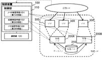
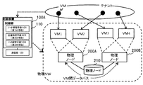
- FIG. 1 is a diagram illustrating a configuration example of a system according to the first embodiment of this invention.
- a physical network hereinafter referred to as “physical NW” in which physical nodes 200A, 200B, and 210 (hereinafter referred to as “physical node 200” when physical nodes 200A and 200B are not particularly distinguished) is arranged.
- physical NW physical network
- physical node 200 when physical nodes 200A and 200B are not particularly distinguished
- the physical node 200 has a function of providing a virtual machine (hereinafter “VM”) 300 on a virtual network (hereinafter “virtual NW”).
- VM virtual machine
- NW virtual network
- Examples of such a physical node 200 include a virtual machine environment construction server.
- FIG. 1 an example in which the VM 300 is operated is given, but a virtual appliance in which an application program or the like is introduced and a specific function can be provided may be used.
- the physical node 210 realizes communication between the physical nodes 200 according to a route instructed from the control device 100. Examples of such a physical node 210 include an open flow switch and a layer 3 switch. Further, instead of the physical node 210, a virtual switch constituted by the physical node 200 may be used.
- a data path is set between the plurality of communication nodes (for example, the VM 300) in order to realize communication on the virtual NW. It is necessary to set and enable communication on the physical NW corresponding to the communication on the virtual NW. Therefore, in the first embodiment, a data path is set between a plurality of communication nodes (for example, the VM 300) included in the virtual NW.
- a plurality of communication nodes (for example, VM 300) included in the virtual NW are operated by a plurality of different physical nodes 200 (for example, physical servers), a plurality of communication nodes (for example, VM 300) on the physical NW are used.
- a data path between the plurality of physical nodes 200 For example, in the example of FIG. 1, each of the VMs 300 included in the virtual NW is operated by the physical node 200A and the physical node 200B, and in order to set a data path between the VMs 300, the physical node 200A and the physical node 200B. It is also necessary to set a data path between and. Therefore, in the first embodiment, a data path is also set between a plurality of physical nodes 200 that realize a plurality of communication nodes (for example, the VM 300) included in the virtual NW.
- the control device 100 specifies a communication node such as a VM corresponding to the service requested by the user, and physically sets the communication node.
- the data path on the NW is dropped and the data path on the physical NW between the communication nodes is set.
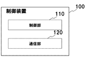
- FIG. 2 is a diagram illustrating a configuration example of the control device 100 according to the first embodiment.
- the control device 100 includes a control unit 110 and a communication unit 120.
- the communication unit 120 is an interface that can communicate with other devices such as the physical node 200 and the physical node 210.
- the communication unit 120 can transmit a predetermined control signal to the physical node 200, for example.
- the communication unit 120 can transmit processing rules and transfer information to the physical node 210.
- the control unit 110 has a function capable of executing a predetermined process.
- the predetermined process executed by the control unit 110 is executed by, for example, a CPU (Central Processing Unit) or an MPU (Micro Processing Unit).
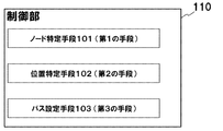
- FIG. 3 is a diagram illustrating a processing example executed by the control unit 110 according to the first embodiment.
- the control unit 110 performs processing performed by each of the node specifying unit 101 (first unit), the position specifying unit 102 (second unit), and the path setting unit 103 (third unit). Can be executed.
- the node specifying unit 101 specifies a communication node corresponding to the service requested by the user.
- the “service requested by the user” uses, for example, a virtual network (for example, vEPC) logically configured using a virtual resource or a virtual resource or a physical resource included in a tenant corresponding to the user.
- Service for example, an existing virtual NW such as a server resource (which may be a VM or a physical server) arranged in a certain (virtual) network, or a network connected to an external network. It may be a user request for.
- the “service requested by the user” may be, for example, a virtual network function (VNF) or a service chain.
- VNF virtual network function
- the node specifying unit 101 plays a role of specifying one or more communication nodes that can provide such a service.
- the “communication node” corresponds to, for example, the above-described server resource (which may be a VM or a physical server).
- An arrow extending from the node specifying unit 101 in FIG. 1 represents an operation in which the node specifying unit 101 specifies a VM 300 corresponding to the upper virtual network (representing a service requested by the user).
- the location specifying unit 102 specifies information related to the location of the communication node specified by the node specifying unit 101 in the physical network.
- the end point information on the physical NW corresponding to the communication node specified by the node specifying unit 101 can be used.
- the end point information is, for example, the address of the communication node specified by the node specifying means 101 (for example, IP (Internet Protocol) address, MAC (Media Access Control) address).
- the end point information may be, for example, the address (for example, IP address, MAC address) of the virtual switch to which the communication node specified by the node specifying unit 101 is connected.
- the end point information may be, for example, the port number of the port used by the communication node in the virtual switch to which the communication node specified by the node specifying unit 101 is connected.
- the end point information may be, for example, the address (for example, IP address, MAC address) of the physical node 200 that realizes the communication node specified by the node specifying unit 101.
- the end point information may be, for example, an address (for example, an IP address or a MAC address) of a physical switch (for example, the physical node 210) corresponding to the communication node identified by the node identifying unit 101.
- the arrow line extending from the position specifying unit 102 in FIG. 1 indicates an operation in which the position specifying unit 102 specifies the end point information of the VM 300 specified by the node specifying unit 101 or the end point information of the physical node 200 corresponding to the VM 300. Represents.
- the path setting unit 103 sets a data path necessary for realizing a service requested by the user on the physical NW, using information on the position of the communication node in the physical network specified by the position specifying unit 102.
- the process of “setting a data path” is realized by setting a flow entry and path information in the physical node 210.
- the flow entry is a processing rule for the physical node 210 to process a packet belonging to the flow.
- the route information is, for example, transfer information used by the physical node 210 to transfer a packet.
- An arrow extending from the path setting unit 103 in FIG. 1 indicates, for example, an operation in which the path setting unit 103 connects the physical nodes 200 specified by the position specifying unit 102 to each other via the physical node 210 and sets a data path. Represents.
- FIG. 4 is a diagram illustrating an example of a table held by the control device according to the first embodiment.
- the upper part of FIG. 4 is a table in which services, communication nodes, and physical node position information are associated with each other.
- the node specifying unit 101 determines what kind of resource is necessary to realize the service A. For example, in the example of FIG. 4, VM1 to VM3 are specified as resources necessary for realizing the service A. Then, the position specifying unit 102 calculates information on the positions of the VM1 to VM3 in the physical NW (which physical node is connected to the end point of the physical NW). In the example of FIG. 4, the addresses and ports of physical nodes that realize VM1 to VM3 are specified.
- a network resource management function called an agent can be used as the node specifying unit 101 and the position specifying unit 102 that perform such operations.
- the table shown in FIG. 4 can be held in the control device 100 as a service definition storage unit and a mapping information storage unit. By doing so, it is possible to speed up the specifying process in the node specifying unit 101 and the position specifying unit 102.
- the service definition storage unit and the mapping information storage unit are realized with one table, but a table (corresponding to the service definition storage unit) that stores the correspondence between the service and the communication node, and the communication node And a table (corresponding to a mapping information storage unit) that stores the correspondence between the location information on the physical NW.
- the path setting means 103 sets a data path between VM1 and VM3 using the topology information of the physical NW and the address and port (port number) of the identified physical node 200. For example, as shown in the lower part of FIG. 4, by setting a data path between the ports of the physical nodes 200 corresponding to VM1 to VM3, for example, a virtual network having a topology in which VM1 to VM3 are connected in a ring shape Can be realized. In the lower arrow, the data path between the physical node 200A and the physical 200B is realized by setting a flow entry and route information in the physical node 210.
- the topology information can be obtained from a topology information storage unit that stores topology information.
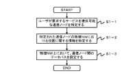
- FIG. 5 is a flowchart illustrating an operation example of the control device 100 according to the first embodiment.
- the node specifying means 101 of the control device 100 specifies one or more communication nodes that can provide the service requested by the user (S1-1).
- the node specifying unit 101 specifies a plurality of VMs 300 as services (virtual NW) requested by the user.
- the position specifying unit 102 of the control device 100 specifies information related to the position of the communication node in the physical NW specified by the node specifying unit 101 (S1-2).
- the position specifying unit 102 specifies end point information on the physical NW for each of the plurality of VMs 300 specified by the node specifying unit 101.
- the location specifying unit 102 includes an address on the physical NW of the physical node 200 that operates each VM 300 and a port corresponding to each VM 300 among the ports of the physical node 200. Specify the port number.
- the path setting unit 103 sets a data path between the communication nodes on the physical NW using the information regarding the position of the communication node in the physical NW specified by the position specifying unit 102 (S1-3).
- the path setting means 103 uses the topology information of the physical NW and the address and port (port number) of the physical node 200 specified by the position specifying means 102 to create a data path between a plurality of VMs 300.
- the path setting unit 103 is a flow entry for enabling the physical nodes 201 to communicate with each other between the physical nodes 200. And path information are set, and a data path is also set between the physical nodes 200.
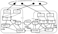
- FIG. 6 is a diagram illustrating another configuration example of the system according to the first embodiment of this invention.
- FIG. 6 a configuration in which a physical NW1 constructed by VXLAN (Virtual eXtensible Local Area Network) and a physical NW2 by NVGRE (Network Virtualization using Generic Generic Routing Encapsulation) is connected by a gateway (GW) is shown. ing.
- VXLAN Virtual eXtensible Local Area Network
- NVGRE Network Virtualization using Generic Generic Routing Encapsulation
- the node specifying unit 101 specifies a communication node corresponding to the service requested by the user.
- the node specifying unit 101 specifies four VMs operating on the three physical servers 200a to 200c (see “(B) mapping” in FIG. 6). Even at this stage, it is not necessary to know what physical network the VM is operating on.
- the position specifying unit 102 specifies information related to the positions of the four VMs in the physical network specified by the node specifying unit 101.
- the end point information on the physical NW corresponding to the four VMs is specified as the information regarding the position in the physical network.
- the position specifying unit 102 specifies the addresses of the physical servers 200a to 200c on which four VMs operate.
- the path setting means 103 sets the data path for realizing the service requested by the user on the physical NW1 and NW2, using the identified end point information and the topology information of the physical NW1 and physical NW2.
- a physical server 200A, a physical switch 210A and a physical server 200B on the physical NW1 side, and a physical switch 210B and a physical server 200C on the physical NW2 side are connected to a gateway (GW).
- a data path is set up to connect via.
- the control device 100 specifies a communication node such as a VM corresponding to the service requested by the user and performs the communication.
- the node is dropped into position information on the physical NW, and a data path on the physical NW between the communication nodes is set. Therefore, after dropping the service on the virtual network requested by the user into the function implementation means and the location information on the physical network, the services on the virtual network are realized on the physical network by connecting them. it can.
- FIG. 7 is a diagram illustrating a configuration example of a system according to the second embodiment of the present invention.
- the control device 100A has substantially the same configuration as the control device of the first embodiment, and includes node specifying means 101 to path setting means 103.
- node specifying means 101 to path setting means 103.
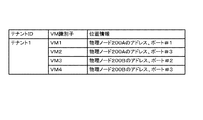
- FIG. 8 is a diagram illustrating an example of a table (corresponding to a tenant definition storage unit and a mapping information storage unit) held by the control device 100A of the present embodiment.
- a table in which tenants, communication nodes (for example, VMs), and position information of physical nodes that operate the communication nodes are associated with each other is shown.
- the node specifying unit 101 determines what resources are required to realize the service requested by the user. For example, the node specifying unit 101 determines the type of resource necessary for realizing the service requested by the user. The node specifying unit 101 specifies a resource necessary for a service requested by a user from resources included in a tenant corresponding to the user. The node specifying unit 101 may calculate a necessary resource amount in addition to the resource type. For example, in the example of FIG. 8, VMs 1 to VM4 shown in FIG. 7 are specified as the resources necessary for the service requested by the user, among the VMs included in the tenant corresponding to the user.
- the node specifying unit 101 associates the tenant 1 with a VM identifier that can uniquely identify each of the VM1 to VM4 required for the service requested by the user.
- the resources required for the service requested by the user are, for example, ICT (Information ⁇ Communication Technology) resources such as servers, storages, and network nodes, and are virtual resources that are virtually realized using the VM. It may be a physical resource.
- the network node is a device that provides functions necessary for network construction, such as a switch, a router, a firewall, and a load balancer.
- the position specifying means 102 determines information related to positions on the physical NW of VM1 to VM4. For example, the position specifying unit 102 determines the address of the physical node 200 that realizes each of the VM1 to VM4 and the port number of the port corresponding to the VM1 to VM4 among the ports of the physical node 200. The location specifying unit 102 specifies the addresses of the VM1 to VM4, the addresses of the virtual switches to which the VM1 to VM4 are connected, the port numbers, and the like as information on the locations of the VM1 to VM4 on the physical NW. May be.
- the position specifying unit 102 includes VM identifiers of VM1 to VM4, addresses of physical nodes 200 that realize each of the VM1 to VM4, and physical nodes corresponding to the VM1 to VM4, respectively.
- the port numbers of 200 ports are associated.
- the path setting means 103 sets a data path between VM1 and VM4 using the topology information of the physical NW and the address and port of the specified physical node 200. For example, as shown in the lower part of FIG. 7, the VM1 to VM4 can communicate with each other by setting a data path between the ports of the physical node 200 corresponding to the VM1 to VM4.
- the path setting unit 103 also sets a data path between the physical node 200A that operates VM1 and VM2, and the physical node 200B that operates VM3 and VM4. As a result, even when some or all of the VM1 to VM4 included in the service requested by the user operate on different physical nodes 200, communication between the VM1 to VM4 becomes possible.
- FIG. 9 is a flowchart showing an operation example of the control device 100A of the second embodiment.
- the node specifying unit 101 of the control device 100A specifies one or more communication nodes necessary for realizing the service requested by the user (S2-1).
- the node specifying unit 101 specifies VM1 to VM4 included in the tenant corresponding to the user as resources necessary for the service requested by the user.
- the position specifying unit 102 of the control device 100A specifies information related to the position of the communication node in the physical NW specified by the node specifying unit 101 (S2-2).
- the position specifying unit 102 assigns the address of the physical node 200 that actually rotates each of the VM1 to VM4 specified by the node specifying unit 101 and each of the VM1 to VM4 among the ports of the physical node 200. Identify the port number of the corresponding port.
- the path setting unit 103 of the control device 100A sets a data path between the communication nodes in the physical NW using the information regarding the position of the communication node in the physical NW specified by the position specifying unit 102 (S2-3). ).
- the path setting unit 103 uses the topology information of the physical NW and the address and port (port number) of the physical node 200 specified by the location specifying unit 102 to create a data path between VM1 and VM4.
- the path setting unit 103 sets, for example, a flow entry and path information for enabling communication between the physical node 200A and the physical node 200B in the physical node 210, and the data path between the physical nodes 200 is also set. Set.
- FIG. 10 is a configuration example of the control device 100A when the control device 100A manages a plurality of resources.
- the control device 100A manages a plurality of resources, and provides a service requested by the user using a part of the managed resources. For example, the control device 100A pools a plurality of resources, and selects a resource necessary for a service requested by the user from the pooled resources.
- the node specifying unit 101 of the control device 100A calculates resources necessary for the service requested by the user, and calculates the calculated resource from the resources included in the tenant corresponding to the user among the plurality of resources to be managed. select.
- the node specifying unit 101 manages a plurality of VMs, and selects a VM necessary for the service requested by the user from among the plurality of managed VMs.
- the plurality of resources managed by the node specifying unit may include physical resources.
- the node identification unit 101 manages a plurality of VMs for each function realized using, for example, a VM.
- Functions realized using the VM are network functions such as a switch, a router, a firewall, and a load balancer.
- the node specifying unit manages, for example, a virtual switch, a virtual router, a virtual firewall, and a virtual load balancer in which the network function is virtually realized by the VM.
- the function realized using the VM may be a storage.
- the node specifying unit 101 abstracts disks and drives in the physical server and manages them as a virtually realized storage pool.
- the functions realized using the VM may be various applications or a desktop, for example.
- the node specifying unit may manage various applications and desktops that are virtually realized using a VM, for example.
- the node specifying unit 101 determines that a load balancer is necessary for a service requested by a user
- the node specifying unit 101 is a virtual load balancer managed and included in a tenant corresponding to the user. Is selected for the tenant.
- the processing of the location specifying unit 102 and the path setting unit 103 after the node specifying unit 101 specifies the resources required for the service requested by the user from the resources pooled in advance is the same as the location specifying in FIG. Since it is the same as the processing of the means 102 and the path setting means 103, detailed description is omitted.
- the control device 100A specifies a communication node such as a VM corresponding to the service requested by the user in order to realize the service requested by the user, and selects the communication node.
- the data is dropped into the position information on the physical NW, and the data path on the physical NW between the communication nodes is set. Therefore, after dropping the service on the virtual network requested by the user into the function implementation means and the location information on the physical network, the services on the virtual network are realized on the physical network by connecting them. it can.
- the control device 100 since the control device 100 has a VM management function, when a request for adding a predetermined resource for a service requested by a user is received, a VM corresponding to the predetermined resource is activated. Can do. Then, the control device 100 uses the node specifying means to the path setting means to specify the communication node of the VM that is newly activated by the fourth means, drops the communication node into the location information on the physical NW, and stores the data on the physical NW. Set the path. Therefore, in the third embodiment, when a user requests to add a resource, a VM is added to realize the addition of the resource, and settings and the like in the physical NW necessary for the addition of the VM are performed. Can do.
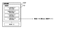
- FIG. 11 is a diagram showing a configuration of a control device according to the third embodiment of the present invention.
- the control unit 110 of the control device 100F includes a node request unit 104 (fourth unit) in addition to the node specifying unit 101, the position specifying unit 102, and the path setting unit 103. It is shown.
- the difference from the first and second embodiments will be mainly described.
- the node request unit 104 activates a VM necessary for providing the service, and provides the VM information to the node specifying unit 101.
- a node request unit 104 can be realized by an interface that gives necessary instructions to a control program such as a hypervisor or VMM (VM manager) that manages VMs on the physical server 200 side.
- the node request unit 104 is described as starting a VM, but the communication node that the node request unit 104 starts is not limited to a VM.
- the node request unit 104 secures resources necessary for providing a service by activating a physical server in a sleep state.
- the node request unit 104 may have a function of terminating a predetermined VM in response to a request from the user.
- the node request unit 104 may have a function of terminating unused VMs and releasing resources.
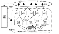
- FIG. 12 is a diagram illustrating a configuration example of a system according to the third embodiment.
- the node identifying unit 101 when a user requests to add a resource and there is no corresponding communication node, the node identifying unit 101 sends a node request unit 104 to the VM corresponding to the added resource.
- Request activation For example, when a node corresponding to a tenant requests addition of a predetermined resource (for example, storage), the node specifying unit 101 sends a VM for realizing the predetermined resource to the node request unit. Request activation.
- a predetermined resource for example, storage
- the node request unit 104 Upon receiving the request, the node request unit 104, for example, newly starts up a VM (see VM5 in FIG. 12) on the physical server shown at the right end of the interruption in FIG. For example, the node requesting unit notifies the node specifying unit of the completion of activation in response to the completion of activation of the new VM.
- the node request unit 104 may notify the node specifying unit 101 of information about the activated VM (for example, an identifier of the activated VM) when the activation of the VM is completed.
- the node specifying unit 101 specifies a newly launched VM as a virtual node included in the service requested by the user. For example, the node specifying unit 101 associates the newly started VM 5 with a predetermined tenant (tenant corresponding to the user).
- the position specifying unit 102 specifies information on the position of the VM 5 in the physical NW added by the node request unit 104 (for example, end point information on the physical NW).
- the location specifying unit 102 specifies, for example, the address of the physical node 200C on which the VM 5 operates and the port corresponding to the VM 5 among the ports of the physical node 200C.
- the path setting means 103 sets a data path between VM1 and VM5. Further, the path setting means 103 sends a flow entry and transfer information for enabling communication between the physical node 200A and the physical node 200C and communication between the physical node 200B and the physical node 200C to the physical node 210. Set. As a result, “communication on the physical NW” necessary for realizing communication between VM1 and VM5 becomes possible.
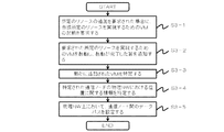
- FIG. 13 is a flowchart showing an operation example of the control device 100F of the third embodiment.
- the node specifying unit 101 of the control device 100F when requested by a user to add a predetermined resource (for example, a storage), the node requesting unit 101 sets a VM for realizing the predetermined resource to the node request unit.
- the activation is requested (S3-1).
- the node specifying unit requests the node requesting unit to start a VM that provides a storage function when the user requests addition of storage.
- the node request unit 104 starts a VM for realizing the requested predetermined resource, and notifies the node specifying unit 101 that the start is completed ( S3-2).
- the node request unit 104 activates a VM that can provide a storage function in response to a request for addition of storage from the node identification unit 101, and notifies that the activation has been completed.
- the node specifying unit 101 When receiving the notification from the node requesting unit 104, the node specifying unit 101 specifies the newly added VM (S3-3). In the example of FIG. 12, the node specifying unit 101 associates the newly started VM 5 with a predetermined tenant (tenant corresponding to the user).
- the location specifying unit 102 specifies information (for example, end point information on the physical NW) related to the location of the VM in the physical NW added by the node request unit (S3-4).
- the position specifying unit 102 specifies, for example, the address of the physical node 200C on which the VM5 operates and the port corresponding to the VM5 among the ports of the physical node 200C.
- the path setting means 103 sets a data path between the existing VMs 1 to 4 and the newly activated VM 5 (S3-5).
- the control device includes a VM management function (node request unit) capable of adding or deleting a communication node (for example, a VM). Therefore, even when a user requests addition of a resource, the service on the virtual network requested by the user is dropped into the function realization means and the location information on the physical network, and then these are connected. Thus, services on the virtual network can be realized on the physical network.
- a VM management function node request unit
- FIG. 14 is a diagram illustrating a configuration example of a system according to the fourth embodiment of this invention.
- the control device 100B manages a plurality of tenants (tenant 1 and tenant 2) is shown. Since the basic configuration of the control device 100B is the same as that of the second or third embodiment, the following description will be focused on the differences.
- the control device 100B has the same configuration as that of the control device 100F of the third embodiment shown in FIG. 11, and includes a node specifying unit 101, an information specifying unit 102, and a path setting unit 103.
- FIG. 15 is a diagram illustrating an example of a table held by the control device 100B of the present embodiment.
- the node specifying unit 101 determines what resources are required to realize the service requested by the user. For example, the node specifying unit determines that a firewall, storage, and switch are necessary for the service requested by the user A, and that a load balancer, storage, and router are necessary for the tenant 2.
- the node specifying unit 101 receives a request regarding the service A from the user A and receives a request regarding the service B from the user B.
- the node identification unit 101 may receive requests regarding the service A and the service B from the same user.
- the timing at which the node specifying unit 101 receives a request regarding the service A and the service B may be a timing different between the service A and the service B.
- the node specifying unit 101 specifies VM1, VM3, and VM4 shown in FIG. 14 from the VM included in the tenant 1 corresponding to the user A for the service A. Further, the node specifying unit 101 specifies VM2, VM5, and VM6 illustrated in FIG. 14 from the VM included in the tenant 2 corresponding to the user B for the service B. Specifically, the node specifying unit 101 associates each identifier of VM1, VM3, and VM4 with tenant 1 for service A, and identifies each identifier of VM2, VM5, and VM6 for service B. Associate with tenant 2.
- the position specifying unit 102 determines which physical node is connected to each of the VM1 to VM6 specified by the node specifying unit 101 on the physical NW. In the example of FIG. 15, for example, the position specifying unit 102 calculates the address of the physical node 200 that operates each of the VM1 to VM6 and the port number of the port corresponding to the VM1 to VM6 among the ports of the physical node 200. .
- the path setting means 103 uses the topology information of the physical NW and the address and port of the physical node 200 specified by the position specifying means 102, between the physical nodes 200 in which each of the VM1, VM3, and VM4 is activated, and Data paths are set between VM2, VM5, and VM6, respectively. For example, as shown in the lower part of FIG. 14, by setting a data path between VM1, VM3, and VM4, VM1, VM3, and VM4 included in tenant 1 can communicate with each other. Similarly, by setting a data path between VM2, VM5, and VM6, VM2, VM5, and VM6 included in tenant 2 can communicate with each other.
- control device 100B of the fourth embodiment may include the node request unit 104 as in the control device of the third embodiment.
- the node request unit 104 activates a VM necessary for providing a service and provides the VM information to the node specification unit 101 when there is a request from the node specification unit 101. . Since the processing of the node requesting unit 104 is the same as that of the node requesting unit 104 of the third embodiment shown in FIG. 11, detailed description thereof is omitted.
- the present invention can also be applied to tenant construction in a multi-tenant environment.
- two tenants are constructed on one physical NW.
- the physical network and the tenant have a one-to-one correspondence as shown in FIG. Can be applied.
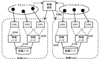
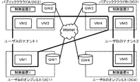
- FIG. 16 is a diagram illustrating another configuration example of the fourth embodiment.
- the node specifying unit 101 of the control device 100C specifies VMs VM1 to VM3 in the physical NW1, which are VMs included in the tenant 1, for the service 1 requested by the user. Further, the node identifying unit 101 identifies VMs 4 to VM6 in the physical NW2 that are VMs included in the tenant 2 for the service 2 requested by the user. Specifically, the node specifying unit 101 associates each identifier of VM1 to VM3 with tenant 1 for service 1 requested by the user, and provides VM4 to VM4 for service 2 requested by the user. Each identifier of the VM 6 is associated with the tenant 2.
- the location specifying unit 102 determines the address of the physical node 200 that realizes each of the VM1 to VM3 specified by the node specifying unit 101 and the port number of the port corresponding to the VM1 to VM3 among the ports of the physical node 200.
- the position specifying means 102 includes the address of the physical node 200 that realizes each of the VM4 to VM6 specified by the node specifying means 101, and the port number of the port corresponding to VM4 to VM6 among the ports of the physical node 200. Is determined.
- the path setting unit 103 sets a data path between the physical nodes 200 in which each of the VM1 to VM3 is activated using the topology of the physical NW1 and the address and port of the physical node 200 specified by the position specifying unit 102. . Further, the path setting means 103 uses the topology of the physical NW 2 and the address and port of the physical node 200 specified by the position specifying means 102 to establish a data path between the physical nodes 200 in which each of the VM4 to VM6 is activated. Set.
- the present invention can also be applied to tenant construction in a multi-tenant environment.
- FIG. 17 is a diagram illustrating a configuration example of a system according to the fifth embodiment of this invention.
- FIG. 18 is a diagram illustrating a configuration example of a control device according to the fifth embodiment of the present invention. 17 and 18, the control device 100D has the same configuration as the control device of the third embodiment, and the control unit 110D of the control device 100D includes a node specifying unit 101D, a position specifying unit 102D, and a path setting. Means 103D and node request means 104D are provided.
- the node specifying unit 101D When the node specifying unit 101D receives a VNF provision request from the user, the node specifying unit 101D specifies a VM corresponding to the VNF. At this time, if a VM capable of realizing the VNF requested by the user is not activated, the node request unit 104D is requested to activate the necessary VM.
- the location specifying unit 102D specifies information related to the location of the VM 300 in the physical NW specified by the node specifying unit 101D. For example, the position specifying unit 102D specifies the address of the physical node 200 on which each of the VM1 to VM3 operates and the port number of the port corresponding to the VM1 to VM3 among the ports of the physical node 200.
- the path setting unit 103D uses the topology information of the physical NW and the information on the location of the VM in the physical network specified by the location specifying unit 102D to generate a data path for realizing the VNF requested by the user on the physical NW. Set.
- the node request unit 104D activates a VM necessary for providing the VNF on the physical server 200 in response to a request from the node identification unit 101D, and provides the VM identification information to the node identification unit 101D.
- the node request unit 104D provides, for example, the identifier of the activated VM to the node specifying unit 101D.
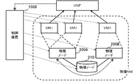
- FIG. 19 is a diagram showing a detailed configuration of the physical node 200 shown in FIG.
- the physical node 200 operates a virtual machine that provides a virtual network function.
- examples of the virtual network function include a firewall (FW), a deep packet inspection (DPI), a load balancer (LB), and the like.
- the communication node 200 is, for example, a server, a switch, a router, or the like.
- the communication node 200 operates a virtual machine that provides a function of a virtual network node (for example, virtual SGW (Serving Gateway), virtual PGW (Packet data network Gateway), virtual MME (Mobility Management Entity)) in the virtual network.
- a virtual network node for example, virtual SGW (Serving Gateway), virtual PGW (Packet data network Gateway), virtual MME (Mobility Management Entity)
- Each virtual network node has the following functions, for example.
- Virtual PGW a function for processing packets (User-Plane function), a function for managing a charging state according to communication (PCEF: Policy and Charging Enforcement Function), and a function for controlling policies such as QoS (Quality of Service) (PCRF) : Policy and Charging Rule Function), virtual SGW: packet processing function (User-Plane function), control signaling processing function (C-Plane function), lawful interception to intercept communications (LI: Lawful Interception) ) Function, virtual MME: function to process control signaling (C-Plane function), function to manage subscriber information of communication system in cooperation with HSS (Home Subscriber Server).
- PCEF Policy and Charging Enforcement Function
- PCRF Policy and Charging Rule Function
- virtual SGW packet processing function (User-Plane function), control signaling processing function (C-Plane function), lawful interception to intercept communications (LI: Lawful Interception)
- virtual MME function to process control signaling (C-Plane function),
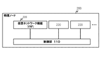
- the physical node 200 includes a control unit 110 capable of constructing a virtual network function (VNF) 220.
- the control unit 110 provides the function of the virtual network node by operating the VNF 220 on the virtual machine.
- a control part 110 may be comprised by the control program which can perform virtualization of a computer, such as a hypervisor (Hypervisor), for example.
- the control unit 110 can start, stop, migrate (migrate a virtual machine to another communication device 100), etc., in response to an instruction from the node request unit 104D described above.
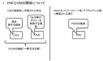
- VNF 220 and VM do not necessarily correspond one-to-one.
- a policy such as VM1 having a charging function included in the PGW function and QoS (QualityQualof Service) included in the PGW function.
- the VM 2 that performs control can be activated separately (function-specific VMs).
- a virtual PGW can also be realized by a VM 3 having a virtual PGW function (appliance type VM).
- FIG. 21 is a diagram illustrating a configuration example of a system according to the fifth embodiment of this invention.
- FIG. 22 is a flowchart showing an operation example of the fifth embodiment of the present invention.
- the user requests the construction of a service chain constructed by connecting VNF1 and VNF2.
- no VM is activated as an initial state. The user here does not need to know the configuration of the physical network and the startup status of the VM, as in the above-described embodiment.
- the node specifying unit 101D requests the node request unit 104D to start VMs corresponding to VNF1 and VNF2 requested by the user (S4-1).
- the node request unit 104D requests the physical node to start up the VM based on the request from the node specifying unit 101D (“VM start up” in FIG. 21, S4-1 in FIG. 22).
- the node request unit 104D In response to the activation of the VM, the node request unit 104D notifies the node identification unit 101D of the completion of the activation of the VM (S4-2).
- the node identification unit 101D receives the VM activation completion notification from the node request unit 104D and identifies the activated VM1 to VM3 (S4-3).
- the position specifying unit 102D specifies information related to the positions of the three VMs 1 to 3 in the physical network specified by the node specifying unit 101D (S4-4).
- the path setting unit 103D sets a data path between the VM1 and VM3 using the information regarding the location of the VM1 to 3 in the physical network and the topology information of the physical NW (S4-5). In addition, the path setting unit 103D sets, in the physical node 210, flow entries and path information for enabling communication between the physical nodes 200 in which each of the VM1 to VM3 is activated. As a result, the data path on the physical NW necessary for realizing the VNF and service chain requested by the user is set.
- the service chain or VNF requested by the user without specifying a specific address or resource is dropped into the function realization means (VM) and the location information on the physical network. Then, by connecting them, the service chain shown in the lower part of FIG. 21 is realized.
- VM function realization means
- a data path between VNFs (VMs) operating on the same physical node can be realized by instructing the path control unit 2101 built in the control unit 110 in the physical node 200.
- FIG. 23 is a diagram for explaining an example of a data path set in the physical node 200 that operates in cooperation with the control device 100D according to the fifth embodiment of the present invention.
- the control unit 110 sets a VNF path via VNF (A), (B), and (C) for the signal (1), and VNF ( A VNF path via A) and (B) is set.
- the path control unit 2101 of the control unit 110 transfers a signal along a route according to the type of signal as illustrated in FIG. 23 according to the setting.
- the type of the signal may be such that a packet is transferred based on, for example, a MAC address or an IP address assigned to the VNF 200. Further, for example, the transfer path can be changed using the type of “bearer” that is a virtual connection for transmitting a packet, the attribute of the packet identified based on the information in the packet, and the like.
- the VNF path can be controlled by the path control unit 2101 based on, for example, the communication volume of the user (terminal 1), the communication load / communication volume of the communication system, the load status of the server 20, and the like.
- the VNF path of a packet belonging to the bearer can be controlled according to the bearer traffic. Further, for example, the VNF path can be changed in response to the amount of communication exceeding a predetermined threshold.
- the path control unit 2101 can select the VNF 200 configuring the VNF path according to the load status of the VM. Further, for example, the path control unit 2101 can preferentially select a VNF 200 having a low virtual machine load among a plurality of VNFs 200 including the same function, and switch the VNF path.
- Such a path control unit 2101 may be configured by, for example, a virtual switch (vSwitch: Virtual Switch) configured by software.
- vSwitch Virtual Switch
- the path setting unit 103D described above sets path information and a flow entry in the switch that functions as the path control unit 2101.
- the present invention can be suitably applied to a system that realizes virtualization of network functions.
- FIG. 24 is a diagram illustrating a configuration example of a system according to the sixth embodiment of this invention.
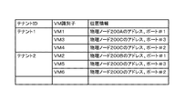
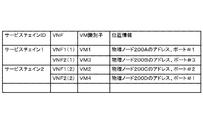
- FIG. 25 is a diagram illustrating an example of a table (corresponding to a tenant definition storage unit and a mapping information storage unit) held by the control device 100A of the present embodiment. Referring to FIG. 25, there is shown a table in which a service chain, a VNF necessary for the service chain, a VM corresponding to the VNF, and position information of a physical node that operates the VM are associated with each other. Since the present embodiment can be realized with the same configuration as that of the fifth embodiment that provides VNF, the following description will focus on the differences.
- the control device of the present embodiment has the same configuration as the control device 100D of the fifth embodiment, and includes node specifying means 101D to node request means 104D (see FIG. 18). Note that the control device 100D may not include the node request unit 104D.
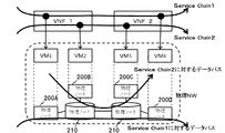
- the node specifying unit 101D When the node specifying unit 101D receives a service chain provision request from the user, the node specifying unit 101D specifies a VM corresponding to the service chain (see arrows extending from VNF1 and VNF2 in FIG. 24).
- the node specifying unit 101D may specify a VNF necessary for the service chain requested by the user and specify a VM corresponding to the VNF.
- the node specifying unit 101D associates the service chain 1 with VNF1 (1) and VNF1 (2), and further associates VNF1 (1) with VM1, VNF1 (2), and VM3. .
- the node specifying unit 101D associates the service chain 2 with VNF1 (2) and VNF2 (2), and further associates VNF1 (2) with VM2, and VNF2 (2) with VM4.
- the node specifying unit 101D requests the node request unit 104D to construct a necessary VNF.
- the position specifying unit 102D specifies information related to the position of the communication node in the physical network specified by the node specifying unit 101D (see arrow lines extending from VM1 to VM4 in FIG. 24 to the physical node). For example, for each of the plurality of VM1 to VM4, the location specifying unit 102D sends the address on the physical NW of the physical node 200 that realizes each of the VM1 to VM4 and the VM1 to VM4 among the ports of the physical node 200. Identify the port number of the corresponding port. As illustrated in FIG. 25, the position specifying unit 102D associates the VM1, the address of the physical node 200, and the port number # 1.
- the path setting unit 103D is a data path for realizing a service chain requested by the user on the physical NW by using the topology information of the physical NW and information on the location of the VM in the physical network specified by the location specifying unit 102D. (Refer to the data path for Service Chain 1 and 2).
- the node request unit 104D activates a VM necessary for providing the VNF on the physical server 200 in response to a request from the node identification unit 101D, and provides the VM identification information to the node identification unit 101D.
- FIG. 26 is a flowchart showing an operation example of the control device 100D according to the sixth embodiment of the present invention.
- the node specifying unit 101D first specifies the VNF corresponding to the service chain requested by the user (S5-1), and then specifies the VM corresponding to the VNF (S5-2).
- the node specifying unit 110 specifies that the service chain 1 passes through VNF1 and VNF2, and VNF1 and VNF2 correspond to VM1 and VM3, respectively.
- the node specifying unit 110 specifies that the service chain 2 passes through VNF1 and VNF2, and that VNF1 and VNF2 correspond to VM2 and VM4, respectively.
- the table in FIG. 25 corresponds to the service chain definition storage unit and the mapping information storage unit.
- the position specifying unit 102 specifies information regarding the positions of the four VMs in the physical network specified by the node specifying unit 101 (refer to the position information of the physical node in FIG. 25, S5-3 in FIG. 26).
- the path setting means 103 sets a data path for realizing the service chain requested by the user on the physical NW using the information on the location of the two sets of VMs in the physical network and the topology information of the physical NW.
- a data path is set between VM1 and VM4 corresponding to service chain 1
- a data path is set between VM2 and VM3 corresponding to service chain 2.
- service chains that provide the same service are constructed using the same VNF, but it is not always necessary to use the same VNF.
- the control device 100 specifies a communication node such as a VM corresponding to the service chain requested by the user and performs the communication.
- the node is dropped into position information on the physical NW, and a data path on the physical NW between the communication nodes is set. Therefore, after dropping the service chain on the virtual network requested by the user into the function implementation means and the location information on the physical network, the service chain on the virtual network is connected to the physical network by connecting them. Can be realized.
- the seventh embodiment of the present invention can adopt a configuration in which a control device is arranged for each physical NW.
- a control device is arranged for each physical NW.
- Each control device manages the physical NW assigned to it.
- the service requested by the user can be constructed across different physical NWs.
- each control device shares the information collected and specified by the respective node specifying means 101 and position specifying means 102, and sets the data path across different physical NWs, thereby providing the service requested by the user. It can be realized.
- a case where a service requested by a user is specified from a communication node included in a tenant corresponding to the user will be described as an example.
- the service may be a service chain or the like.
- FIG. 28 is a diagram illustrating an example of a table (corresponding to a tenant definition storage unit and a mapping information storage unit) created by the control devices 1 and 2 according to the present embodiment exchanging information.
- the tenant corresponding to the user
- the VM identifier (VM1 to VM4) for realizing the service, and each of the VM1 to VM4 are managed.
- the control device (the control device 1 or the control device 2) and the positional information on the physical NW of the VM1 to VM4 are stored in association with each other.
- information (VM identifier and physical node position information) on VM1 and VM2 managed by the control device 1 is specified by the control device 1. Further, information (VM identifier and physical node position information) regarding VM 3 and VM 4 managed by the control device 2 is specified by the control device 2.
- the control device 1 and the control device 2 share the information specified by the own device (the identifier of the VM managed by the own device and the location information of the physical node).
- the control device 1 and the control device 2 exchange the information by, for example, BGP (Border Gateway Protocol).
- BGP Border Gateway Protocol
- the control device 1 and the control device 2 can also exchange the position information on the VM and the physical NW by exchanging the table shown in FIG.
- the control device 1 transmits the upper stage of the table shown in FIG. 28 (the part specified by the control device 1) to the control device 2.
- the control device 2 transmits the lower part of the table shown in FIG. 28 (the part specified by the control device 2) to the control device 1.
- the control apparatus 1 and the control apparatus 2 can exchange the table shown in FIG.
- control device 1 and the control device 2 may include, for example, topology information of the physical NW.
- the path setting means 103 of the control device 1 and the control device 2 sets the data path on the physical NW necessary for realizing the service requested by the user, using the specified location information on the physical NW.
- either the control device 1 or the control device 2 may set the entire data path based on the shared information (for example, the table shown in FIG. 28) instead of the other control device. Good.
- the control device 1 sets processing rules and transfer information for transferring packets from the VM1 or VM2 to the physical node 210B for the physical node 210A. Further, the control device 1 sets a processing rule and transfer information for transferring a packet from the VM 3 or VM 4 transferred from the physical node 210B to the VM 1 or VM 2 for the physical node 210A.
- control device 2 sets processing rules and transfer information for transferring packets from the VM 3 or VM 4 to the physical node 210A for the physical node 210B. Further, the control device 2 sets a processing rule and transfer information for transferring the packet from the VM1 or VM2 transferred from the physical node 210A to the VM3 or VM4 to the physical node 210B.
- control device 1 and the control device 2 can set the data path between the VM1 and the VM4 in the physical NW, and can realize the service requested by the user.
- the present invention can also be applied to realization of a tenant, a service chain, etc. between physically separated networks, for example, between networks in different DCs.
- FIG. 29 is a diagram showing the configuration of the eighth exemplary embodiment of the present invention.
- the basic configuration is the same as that of the seventh embodiment shown in FIG. 27, in this embodiment, for example, the communication protocol (tunneling protocol) is different between the physical NW1 and the physical NW2, and the data is not changed as it is. The difference is that the path cannot be set.
- the difference will be mainly described.
- the physical network is constructed with a different tunneling protocol (VXLAN / NvGRE as an example).
- VXLAN Virtual eXtensible Local Area Network
- NVGRE Network Virtualization using Generic Routing Encapsulation
- GW1 and GW2 gateways
- the space between the physical NW1 and the physical NW2 may be a WAN (WideWArea Network) or the like.
- the control unit 110 of the control device 100E1 and the control device 100E2 exchanges topology information of the physical NW1 and the physical NW2 via the communication unit 120, for example.
- the control device 100E1 and the control device 100E2 exchange the topology information by BGP.
- the node specifying means 101 of the control device 100E1 and the control device 100E2 specifies a VM necessary for realizing the service requested by the user from the VMs included in the tenant corresponding to the user.
- the node specifying unit 101 of the control device 100E1 and the control device 100E2 specifies that the service requested by the user requires VM1 to VM4 among the VMs included in the tenant corresponding to the user.
- Each node specifying unit 101 for example, for a service requested by a user, a tenant corresponding to the user and a VM identifier that can uniquely identify each of VM1 to VM4 required for the service requested by the user Associate.
- the position specifying unit 102 of the control device 100E1 and the control device 100E2 specifies information regarding the positions on the physical NW of the VM1 to VM4 specified by the node specifying unit 101.
- the position specifying unit 102 of the control device 100E1 specifies information related to the position on the physical NW1 for the VM1 and the VM2 in the physical NW1 managed by the control device E1.
- the position specifying unit 102 of the control device 100E1 uses the addresses of the VM1 and VM2 and the addresses of the virtual switches to which the VM1 and VM2 are connected as information on the positions of the VM1 and VM2 on the physical NW1. Specify port number, etc.
- the position specifying unit 102 of the control device 100E2 specifies information related to the position on the physical NW2 for the VM3 and the VM4 in the physical NW2 managed by the control device E2. Specifically, the position specifying unit 102 of the control device 100E2 uses the addresses of the VM3 and VM4 and the addresses of the virtual switches to which the VM3 and VM4 are connected as information regarding the positions of the VM3 and VM4 on the physical NW1. Specify port number, etc.
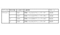
- FIG. 30 is a diagram illustrating an example of a table held by the control devices 100E1 and 100E2 according to the eighth embodiment. The difference from the table held by the control device of the seventh embodiment illustrated in FIG. 28 is that a protocol storage area is added.
- a tenant corresponding to the user, a VM identifier for realizing the service requested by the user (VM1 to VM4), and the VM1 to VM4 are stored in association with the control device (control device 1 or control device 2) that manages each of the above, the location information of the physical node that realizes the VM1 to VM4, and the protocol in the physical NW that includes the VM1 to VM2. ing.
- the control device control device 1 or control device 2
- the control device controls the control device (control device 1 or control device 2) that manages each of the above, the location information of the physical node that realizes the VM1 to VM4, and the protocol in the physical NW that includes the VM1 to VM2.
- the control device 100E1 and the control device 100E2 exchanges information regarding the tunneling protocol (VXLAN / NvGRE) in the managed NW, for example, via the communication unit 120.
- the control unit 110 of the control device 100E1 and the control device 100E2 shares the VM location information (the VM identifier managed by the own device and the physical node location information) specified by the own device.
- the control device 100E1 and the control device 100E2 exchange the position information of the VM by, for example, BGP.
- the path setting means 103 of the control device 100E1 and the control device 100E2 uses the physical NW necessary for realizing the service requested by the user based on the VM location information specified by the own device and the shared VM location information. Set the upper data path.
- the path setting unit 103 of the control device 100E1 sets a data path between VM1 and VM2 in the physical NW1, for example. Further, the path setting unit 103 of the control device 100E1 sets a processing rule and transfer information for transferring a packet from the VM1 or VM2 to the GW1 for the physical node 210A. Further, the control device 100E1 sets processing rules and transfer information for transferring, to the VM1 or VM2, the packet from the VM3 or VM4 transferred from the GW1 to the physical node 210A.
- the tunneling protocol of the physical NW1 is VXLAN, which may be different from the communication protocol on the Internet.
- the path setting means 103 of the control device 100E1 converts packets transferred from VM1 and VM2 based on VXLAN to GW1 into a communication protocol in the Internet, and transfers the packet to the Internet. Set processing rules and transfer information.
- the path setting means 103 of the control device 100E1 decapsulates transfer information (address, etc.) based on VXLAN from the packet received from the physical node 210A for the GW1, and uses the communication protocol on the Internet for the packet. Instructs to encapsulate transfer information (address, etc.) compliant with.
- the path setting means 103 of the control device 100E1 converts, for example, a packet transferred to the GW1 based on the communication protocol in the Internet into a VXLAN that is a tunneling protocol of the physical NW1, and sends it to the physical node 210A.
- Set processing rules and transfer information for transfer Specifically, the path setting means 103 of the control device 100E1 decapsulates transfer information (address, etc.) based on the communication protocol on the Internet from the received packet to the GW1, and transfers the packet in accordance with VXLAN. Indicates that information (address, etc.) is to be encapsulated.
- the path setting means 103 of the control device 100E2 sets a data path between VM3 and VM4 in the physical NW2, for example. Specifically, the path setting unit 103 of the control device 100E2 sets a data path between the physical node 200B in which the VM3 is activated and the physical node 200C in which the VM4 is activated. On the other hand, processing rules and transfer information for enabling communication between the physical node 200B and the physical node 200C are set. Further, the path setting unit 103 of the control device 100E1 sets a processing rule and transfer information for transferring a packet from the VM1 or VM2 to the GW1 for the physical node 210A. Further, the control device 1 sets processing rules and transfer information for transferring the packet from the VM 3 or VM 4 transferred from the GW 1 to the VM 1 or VM 2 for the physical node 210A.
- the tunneling protocol of the physical NW2 is NvGRE and may be different from the communication protocol on the Internet.
- the path setting unit 103 of the control device 100E2 converts packets transferred from the VM3 and VM4 based on the NvGRE to the GW2 into a communication protocol in the Internet and transfers the packet to the Internet.
- Set processing rules and transfer information Specifically, the path setting unit 103 of the control device 100E2 decapsulates transfer information (address, etc.) based on NvGRE from a packet received from the physical node 210B for the GW2, for example, and encapsulates the packet on the Internet. Instructs to encapsulate transfer information (address, etc.) conforming to the communication protocol.
- the path setting unit 103 of the control device 100E2 converts, for example, a packet transferred to the GW2 based on the communication protocol in the Internet into NvGRE, which is a tunneling protocol of the physical NW2, and sends it to the physical node 210B.
- NvGRE which is a tunneling protocol of the physical NW2
- the path setting means 103 of the control device 100E2 decapsulates transfer information (address, etc.) based on a communication protocol on the Internet from the received packet to the GW2, and transfers information (NvGRE-compliant transfer information ( Address) is encapsulated.
- control device 100E1 and the control device 100E2 can set the data path between the VM1 and the VM4 in the physical NW, and can realize the service requested by the user.
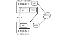
- FIG. 31 is a diagram illustrating another configuration example of the system according to the eighth embodiment.
- the physical NW1 is a data center (data center (DC) 1) that provides a public cloud
- the physical NW2 is on-premises (DC2). That is, a tenant is constructed using a VM provided from a public cloud and a VM prepared on-premises, for example, a form called a hybrid cloud.
- the control device 1 that manages the physical NW1 in the DC1 that provides the public cloud is different from the control device 2 that manages the physical NW2 in the on-premises (DC2). Therefore, in order to set up a data path on the physical NW necessary for realizing a predetermined service using a communication node included in the tenant when trying to construct one tenant, the control device 1 and the control device Information needs to be exchanged between the two.
- the tunneling protocol may be different between the physical NW1 in the DC1 that provides the public cloud and the physical NW2 in the on-premises (DC2).
- the tunneling protocol of the physical NW1 in the DC1 that provides the public cloud is VXLAN
- the tunneling protocol of the physical NW2 in the on-premises (DC2) is NvGRE.
- the control device 1 and the control device 2 in FIG. 31 specify the communication node necessary for realizing the service requested by the user, specify the location information on the physical NW of the specified communication node, and specify the specified A data path is set between the communication nodes based on the position information.
- the node specifying means 101 of the control device 1 and the control device 2 specifies the communication nodes required to realize the service requested by the user as VM1 to VM3.
- the position specifying means 102 of the control device 1 and the control device 2 specifies the position information on the physical NW of each of the VM1 to VM3.
- the control device 1 specifies the location information of the VM1 and the VM2 in the physical NW1 in the DC1 that provides the public cloud to be managed.
- the control device 2 specifies the position information of the VM 3 in the physical NW 2 in the on-premises (DC 2) to be managed.
- the path setting means 103 of the control device 1 and the control device 2 sets a data path between VM1 to VM3 based on the specified position information.
- the physical NW1 in the DC1 that provides the public cloud, the physical NW2 in the on-premises (DC2), and the Internet may have different communication protocols.
- the path setting means 103 of the control device 1 sets, for example, processing rules and transfer information for mutually converting the communication protocol in the physical NW1 and the communication protocol in the Internet for the GW1.
- the path setting unit 103 of the control device 2 sets, for example, processing rules and transfer information for mutually converting the communication protocol in the physical NW2 and the communication protocol in the Internet for the GW2.
- the specific processing of the path setting unit 103 of the control device 1 and the control device 2 is the same as that of the path setting unit 103 of the control device 100E1 and the control device 100E2 illustrated in FIG.
- the control device 1 and the control device 2 can set a data path between the VM1, VM2, and VM3 that exist in different DCs, and can realize the service requested by the user. Become.
- either one of the control device 1 or the control device 2 stores the position information of VM1 to VM3.
- Identification or setting of a data path between VM1 to VM3 may be executed.
- the control device 2 in the on-premises (DC2) specifies the location information of the VM1 to VM3 based on the topology information of the physical NW1 acquired from the control device 1 in the DC1 that provides the public cloud, and the VM1 to VM3. Set the data path between.
- control device 2 requests the control device 1 to set the data path between the VM1 and the VM2 in the physical NW1 of the DC1, and to set the processing rule and transfer information for the GW1, so that the VM1 ⁇ A data path between VMs 3 may be set.
- FIG. 32 is a diagram illustrating another configuration example of the system according to the eighth embodiment.
- the system according to the eighth embodiment includes, for example, user A's on-premises DC 1, public cloud DC 2, public cloud DC 3, and user B's on-premises DC 4.
- the system in the eighth embodiment includes a tenant 1 corresponding to the user A and a tenant 2 corresponding to the user B, and a multi-tenant is provided by a plurality of DCs.
- the tenant 1 corresponding to the user A includes VM1 in DC1, VM2 and VM3 in DC2, and VM4 in DC3.
- the tenant 2 corresponding to the user B includes a VM 5 in the DC 3 and a VM 6 in the DC 4.
- the node specifying means 101 of the control device 1, the control device 2, and the control device 3 specifies VM1 to VM4 included in the tenant 1 corresponding to the user A as VMs that realize the service requested by the user A.
- the position specifying means 102 of the control device 1, the control device 2, and the control device 3 specifies position information on the physical NW of VM1 to VM4.
- the position specifying unit 102 of the control device 1 specifies position information on the physical NW of the VM 1 in the DC 1 managed by the own device.
- the position specifying means 102 of the control device 2 and the control device 3 also specify the position information on the physical NW of the VM2 and VM3 in the DC2 and the VM4 in the DC3, respectively.
- the path setting means 103 of the control device 1, the control device 2, and the control device 3 sets a data path between VM1 and VM4.
- each of DC1 to DC3 and the Internet may have different communication protocols.
- the path setting means 103 of the control device 1, the control device 2, and the control device 3 respectively change the communication protocol of DC1 to DC3 and the communication protocol of the Internet to each of GW1 to GW3.
- the specific processing of the path setting unit 103 of the control device 1, the control device 2, and the control device 3 is the same as that of the control device 100E1 and the path setting unit 103 of the control device 100E2 illustrated in FIG. Explanation is omitted.
- the path setting means 103 of the control device 1, the control device 2, and the control device 3 can set the data path between each of VM1 to VM4 existing in different DCs, and the service requested by the user A Can be realized.
- one of the control device 1, the control device 2, and the control device 3 has the VM1 to VM4 based on information acquired from another control device (such as topology information of the physical NW managed by the other control device).
- Specification of position information and setting of a data path between VM1 and VM4 may be executed.
- the control device 1 in the on-premises (DC1) specifies the location information of the VM1 to VM4 based on the topology information of the physical NW in the DC2 and DC3 acquired from the other control devices 2 and 3, and the like.
- the data path setting between VM1 to VM4 is executed.
- control device 1 requests the control device 2 and the control device 3 to set the data path on the physical NW in the DC2 and the DC3 and the setting for the GW2 of the DC2 and the GW3 of the DC3.
- Data path setting between VM1 to VM4 may be executed.
- the node specifying means 101 of the control device 3 and the control device 4 specifies VM5 and VM6 included in the tenant 2 corresponding to the user A as VMs that realize the service requested by the user B.
- the position specifying means 102 of the control device 3 and the control device 4 specifies the position information on the physical NW of the VMs 5 and 6.
- the position specifying unit 102 of the control device 3 specifies position information on the physical NW of the VM 5 in the DC 3 managed by the own device.
- the position specifying unit 102 of the control device 4 also specifies position information on the physical NW of the VM 6 in the DC 4.
- the path setting unit 103 of the control device 3 and the control device 4 sets a data path between the VM 5 and the VM 6.
- DC3, DC4, and the Internet may have different communication protocols.
- the path setting means 103 of the control device 3 and the control device 4 respectively transfers processing rules and transfers for changing the communication protocols of DC3 and DC4 and the communication protocol of the Internet to each of GW3 and GW4. Set the information.
- the specific processing of the path setting means 103 of the control device 3 and the control device 4 is the same as that of the path setting means 103 of the control device 100E1 and the control device 100E2 illustrated in FIG. The Thereby, the path setting means 103 of the control device 3 and the control device 4 can set a data path between each of the VMs 5 and 6 existing in different DCs, and realize the service requested by the user B. Is possible.
- one of the control device 3 and the control device 4 is based on information acquired from another control device (such as topology information of a physical NW managed by the other control device).
- the location information of VM1 to VM3 and the setting of the data path between VM1 to VM3 may be executed.
- the present invention can be applied even when the network is physically different and the communication protocol is different.
- each request means of the control device of each embodiment described above can also be realized by a computer program that causes a computer constituting the control device to execute the above-described processes using its hardware.
- the first physical network is occupied by a predetermined user
- the second physical network is a control device that can be used by a plurality of users.
- the first means is a control device that identifies a communication node necessary for a service requested by the user from communication nodes included in a tenant corresponding to the user.
- the first means specifies a communication node necessary for a service requested by a plurality of users from communication nodes included in a plurality of tenants corresponding to the plurality of users
- the third means is a control device for setting a data path for realizing the service on the first physical network for each of the plurality of tenants.
- the first control device receives information related to a communication node included in the second network identified as a communication node necessary for the service from the second control device.
- the first control device is a control device that receives, from the second control device, information related to positions of the identified plurality of communication nodes in the second physical network.
- the first and second control devices share the topology information of the first and second physical networks
- the second means is a control device that specifies information related to a position of each of the specified plurality of communication nodes in the first and second physical networks based on the topology information.
- the third means is a control device that sets processing for converting the protocol for a communication device located at the boundary of a plurality of networks constructed with different protocols.
- the third means is a control device for setting a communication device located at the boundary of the first network to process a packet to be transmitted with a destination protocol.
Abstract
Priority Applications (6)
| Application Number | Priority Date | Filing Date | Title |
|---|---|---|---|
| EP16772994.6A EP3280101A4 (fr) | 2015-03-31 | 2016-03-30 | Dispositif de commande, procédé de commande et programme |
| US15/562,103 US20180077048A1 (en) | 2015-03-31 | 2016-03-30 | Controller, control method and program |
| JP2017510124A JP6477864B2 (ja) | 2015-03-31 | 2016-03-30 | 制御装置、制御方法及びプログラム |
| RU2017134817A RU2676452C1 (ru) | 2015-03-31 | 2016-03-30 | Контроллер, способ управления и программа |
| CN201680020273.XA CN107534603A (zh) | 2015-03-31 | 2016-03-30 | 控制器、控制方法和程序 |
| KR1020177031380A KR20170134556A (ko) | 2015-03-31 | 2016-03-30 | 제어기, 제어 방법 및 프로그램 |
Applications Claiming Priority (2)
| Application Number | Priority Date | Filing Date | Title |
|---|---|---|---|
| JP2015-073890 | 2015-03-31 | ||
| JP2015073890 | 2015-03-31 |
Publications (1)
| Publication Number | Publication Date |
|---|---|
| WO2016159113A1 true WO2016159113A1 (fr) | 2016-10-06 |
Family
ID=57007210
Family Applications (1)
| Application Number | Title | Priority Date | Filing Date |
|---|---|---|---|
| PCT/JP2016/060446 WO2016159113A1 (fr) | 2015-03-31 | 2016-03-30 | Dispositif de commande, procédé de commande et programme |
Country Status (9)
| Country | Link |
|---|---|
| US (1) | US20180077048A1 (fr) |
| EP (1) | EP3280101A4 (fr) |
| JP (1) | JP6477864B2 (fr) |
| KR (1) | KR20170134556A (fr) |
| CN (1) | CN107534603A (fr) |
| AR (1) | AR104150A1 (fr) |
| RU (1) | RU2676452C1 (fr) |
| TW (1) | TW201707421A (fr) |
| WO (1) | WO2016159113A1 (fr) |
Cited By (10)
| Publication number | Priority date | Publication date | Assignee | Title |
|---|---|---|---|---|
| WO2019116928A1 (fr) * | 2017-12-11 | 2019-06-20 | ソニー株式会社 | Dispositif de communication, structure de données, procédé de communication, et programme informatique |
| JP2019525669A (ja) * | 2016-08-27 | 2019-09-05 | ニシラ, インコーポレイテッド | ネットワーク制御システムのパブリッククラウドへの拡張 |
| US10805330B2 (en) | 2016-08-31 | 2020-10-13 | Nicira, Inc. | Identifying and handling threats to data compute nodes in public cloud |
| US10812413B2 (en) | 2016-08-27 | 2020-10-20 | Nicira, Inc. | Logical network domains stretched between public and private datacenters |
| US10862753B2 (en) | 2017-12-04 | 2020-12-08 | Nicira, Inc. | High availability for stateful services in public cloud logical networks |
| US11115465B2 (en) | 2017-08-24 | 2021-09-07 | Nicira, Inc. | Accessing endpoints in logical networks and public cloud service providers native networks using a single network interface and a single routing table |
| US11196591B2 (en) | 2018-08-24 | 2021-12-07 | Vmware, Inc. | Centralized overlay gateway in public cloud |
| US11343229B2 (en) | 2018-06-28 | 2022-05-24 | Vmware, Inc. | Managed forwarding element detecting invalid packet addresses |
| US11374794B2 (en) | 2018-08-24 | 2022-06-28 | Vmware, Inc. | Transitive routing in public cloud |
| US11695697B2 (en) | 2017-08-27 | 2023-07-04 | Nicira, Inc. | Performing in-line service in public cloud |
Families Citing this family (1)
| Publication number | Priority date | Publication date | Assignee | Title |
|---|---|---|---|---|
| CN114546563B (zh) * | 2022-02-23 | 2023-04-28 | 北京京航计算通讯研究所 | 一种多租户页面访问控制方法和系统 |
Citations (2)
| Publication number | Priority date | Publication date | Assignee | Title |
|---|---|---|---|---|
| JP2009075718A (ja) * | 2007-09-19 | 2009-04-09 | Hitachi Ltd | 仮想i/oパスの管理方法、情報処理システム及びプログラム |
| WO2015041706A1 (fr) * | 2013-09-23 | 2015-03-26 | Mcafee, Inc. | Fourniture d'un trajet rapide entre deux entités |
Family Cites Families (12)
| Publication number | Priority date | Publication date | Assignee | Title |
|---|---|---|---|---|
| JP3573208B2 (ja) * | 1992-11-06 | 2004-10-06 | エイ・ティ・アンド・ティ・コーポレーション | 広帯域通信網の電話通信呼経路の設定 |
| RU2461150C1 (ru) * | 2008-10-17 | 2012-09-10 | Телефонактиеболагет Лм Эрикссон (Пабл) | Способ и устройства для выбора и указания услуги |
| JP5314510B2 (ja) * | 2009-06-17 | 2013-10-16 | 日本電信電話株式会社 | 帯域管理制御システム及び帯域管理制御方法 |
| JP5678508B2 (ja) * | 2010-07-29 | 2015-03-04 | 日本電気株式会社 | シンクライアントシステム、管理サーバ、仮想マシン作成管理方法及び仮想マシン作成管理プログラム |
| US9489224B2 (en) * | 2010-12-28 | 2016-11-08 | Nec Corporation | Network virtualization system, physical node, and virtual interface identification method in virtual machine |
| WO2012170016A1 (fr) * | 2011-06-07 | 2012-12-13 | Hewlett-Packard Development Company, L.P. | Architecture de réseau partagé extensible pour centres de données virtualisés |
| JP2013157855A (ja) * | 2012-01-31 | 2013-08-15 | Nec Corp | 仮想ネットワークの接続方法、仮想ネットワーク接続装置およびプログラム |
| JP2015511074A (ja) * | 2012-03-23 | 2015-04-13 | 日本電気株式会社 | 通信のためのシステム及び方法 |
| US9929919B2 (en) * | 2012-10-30 | 2018-03-27 | Futurewei Technologies, Inc. | System and method for virtual network abstraction and switching |
| CN103051565B (zh) * | 2013-01-04 | 2018-01-05 | 中兴通讯股份有限公司 | 一种等级软件定义网络控制器的架构系统及实现方法 |
| US10291515B2 (en) * | 2013-04-10 | 2019-05-14 | Huawei Technologies Co., Ltd. | System and method for a control plane reference model framework |
| US10009284B2 (en) * | 2013-06-28 | 2018-06-26 | Verizon Patent And Licensing Inc. | Policy-based session establishment and transfer in a virtualized/cloud environment |
-
2016
- 2016-03-30 JP JP2017510124A patent/JP6477864B2/ja active Active
- 2016-03-30 RU RU2017134817A patent/RU2676452C1/ru active
- 2016-03-30 WO PCT/JP2016/060446 patent/WO2016159113A1/fr active Application Filing
- 2016-03-30 KR KR1020177031380A patent/KR20170134556A/ko not_active Application Discontinuation
- 2016-03-30 TW TW105109939A patent/TW201707421A/zh unknown
- 2016-03-30 EP EP16772994.6A patent/EP3280101A4/fr not_active Withdrawn
- 2016-03-30 CN CN201680020273.XA patent/CN107534603A/zh active Pending
- 2016-03-30 US US15/562,103 patent/US20180077048A1/en not_active Abandoned
- 2016-03-31 AR ARP160100862A patent/AR104150A1/es unknown
Patent Citations (2)
| Publication number | Priority date | Publication date | Assignee | Title |
|---|---|---|---|---|
| JP2009075718A (ja) * | 2007-09-19 | 2009-04-09 | Hitachi Ltd | 仮想i/oパスの管理方法、情報処理システム及びプログラム |
| WO2015041706A1 (fr) * | 2013-09-23 | 2015-03-26 | Mcafee, Inc. | Fourniture d'un trajet rapide entre deux entités |
Non-Patent Citations (2)
| Title |
|---|
| KOJI TSUBOUCHI ET AL.: "NFV Management and Orchestration Technology to Automatically Build Network Services on Demand", IEICE TECHNICAL REPORT, vol. 114, no. 206, 4 September 2014 (2014-09-04), pages 107 - 112 * |
| See also references of EP3280101A4 * |
Cited By (15)
| Publication number | Priority date | Publication date | Assignee | Title |
|---|---|---|---|---|
| US11018993B2 (en) | 2016-08-27 | 2021-05-25 | Nicira, Inc. | Distributed network encryption for logical network implemented in public cloud |
| JP7190595B2 (ja) | 2016-08-27 | 2022-12-15 | ニシラ, インコーポレイテッド | ネットワーク制御システムのパブリッククラウドへの拡張 |
| US10812413B2 (en) | 2016-08-27 | 2020-10-20 | Nicira, Inc. | Logical network domains stretched between public and private datacenters |
| US10924431B2 (en) | 2016-08-27 | 2021-02-16 | Nicira, Inc. | Distributed processing of north-south traffic for logical network in public cloud |
| JP2019525669A (ja) * | 2016-08-27 | 2019-09-05 | ニシラ, インコーポレイテッド | ネットワーク制御システムのパブリッククラウドへの拡張 |
| US11792138B2 (en) | 2016-08-27 | 2023-10-17 | Nicira, Inc. | Centralized processing of north-south traffic for logical network in public cloud |
| JP2022058523A (ja) * | 2016-08-27 | 2022-04-12 | ニシラ, インコーポレイテッド | ネットワーク制御システムのパブリッククラウドへの拡張 |
| US10805330B2 (en) | 2016-08-31 | 2020-10-13 | Nicira, Inc. | Identifying and handling threats to data compute nodes in public cloud |
| US11115465B2 (en) | 2017-08-24 | 2021-09-07 | Nicira, Inc. | Accessing endpoints in logical networks and public cloud service providers native networks using a single network interface and a single routing table |
| US11695697B2 (en) | 2017-08-27 | 2023-07-04 | Nicira, Inc. | Performing in-line service in public cloud |
| US10862753B2 (en) | 2017-12-04 | 2020-12-08 | Nicira, Inc. | High availability for stateful services in public cloud logical networks |
| WO2019116928A1 (fr) * | 2017-12-11 | 2019-06-20 | ソニー株式会社 | Dispositif de communication, structure de données, procédé de communication, et programme informatique |
| US11343229B2 (en) | 2018-06-28 | 2022-05-24 | Vmware, Inc. | Managed forwarding element detecting invalid packet addresses |
| US11374794B2 (en) | 2018-08-24 | 2022-06-28 | Vmware, Inc. | Transitive routing in public cloud |
| US11196591B2 (en) | 2018-08-24 | 2021-12-07 | Vmware, Inc. | Centralized overlay gateway in public cloud |
Also Published As
| Publication number | Publication date |
|---|---|
| KR20170134556A (ko) | 2017-12-06 |
| US20180077048A1 (en) | 2018-03-15 |
| AR104150A1 (es) | 2017-06-28 |
| RU2676452C1 (ru) | 2018-12-28 |
| EP3280101A4 (fr) | 2018-09-05 |
| TW201707421A (zh) | 2017-02-16 |
| CN107534603A (zh) | 2018-01-02 |
| JPWO2016159113A1 (ja) | 2018-01-18 |
| JP6477864B2 (ja) | 2019-03-06 |
| EP3280101A1 (fr) | 2018-02-07 |
Similar Documents
| Publication | Publication Date | Title |
|---|---|---|
| JP6477864B2 (ja) | 制御装置、制御方法及びプログラム | |
| WO2016159192A1 (fr) | Dispositif de commande, procédé de commande, et programme | |
| JP6538986B2 (ja) | 仮想マシンパケット制御 | |
| US9178828B2 (en) | Architecture for agentless service insertion | |
| JP6574304B2 (ja) | 仮想ネットワーク管理 | |
| JP5835846B2 (ja) | ネットワークシステム及び仮想ノードのマイグレーション方法 | |
| Dixon et al. | Software defined networking to support the software defined environment | |
| JP6236221B2 (ja) | 管理プログラム、管理装置、およびネットワークシステム | |
| CN103763367A (zh) | 一种云计算数据中心分布式虚拟网络设计方法及系统 | |
| CN103548376A (zh) | 通过openflow数据平面在云计算机中实现epc | |
| TW201603531A (zh) | 全網域服務控制器 | |
| US20210204191A1 (en) | Inter-slice sharing in 5g core networks | |
| JP5904285B2 (ja) | 通信システム、仮想ネットワーク管理装置、通信ノード、通信方法及びプログラム | |
| JP5063726B2 (ja) | 仮想ノード装置のコンフィグ制御方法 | |
| WO2016159057A1 (fr) | Dispositif de commande, procédé de commande et programme | |
| Chou et al. | Design of SFC Management System based on SDN and NFV | |
| Christodoulopoulos et al. | Software Defined Networks: A case for QoS implementation at the Greek School Network | |
| Leea et al. | Container-based Management Platform for Scalable Service Clusters Provisioning |
Legal Events
| Date | Code | Title | Description |
|---|---|---|---|
| 121 | Ep: the epo has been informed by wipo that ep was designated in this application |
Ref document number: 16772994 Country of ref document: EP Kind code of ref document: A1 |
|
| WWE | Wipo information: entry into national phase |
Ref document number: 15562103 Country of ref document: US |
|
| ENP | Entry into the national phase |
Ref document number: 2017510124 Country of ref document: JP Kind code of ref document: A |
|
| NENP | Non-entry into the national phase |
Ref country code: DE |
|
| WWE | Wipo information: entry into national phase |
Ref document number: 2017134817 Country of ref document: RU |
|
| ENP | Entry into the national phase |
Ref document number: 20177031380 Country of ref document: KR Kind code of ref document: A |