WO2016158146A1 - すきま腐食検知器を組み込んだ構造物 - Google Patents
すきま腐食検知器を組み込んだ構造物 Download PDFInfo
- Publication number
- WO2016158146A1 WO2016158146A1 PCT/JP2016/056011 JP2016056011W WO2016158146A1 WO 2016158146 A1 WO2016158146 A1 WO 2016158146A1 JP 2016056011 W JP2016056011 W JP 2016056011W WO 2016158146 A1 WO2016158146 A1 WO 2016158146A1
- Authority
- WO
- WIPO (PCT)
- Prior art keywords
- crevice corrosion
- gap
- corrosion detector
- detector
- crevice
- Prior art date
- Legal status (The legal status is an assumption and is not a legal conclusion. Google has not performed a legal analysis and makes no representation as to the accuracy of the status listed.)
- Ceased
Links
Images





Classifications
-
- G—PHYSICS
- G01—MEASURING; TESTING
- G01N—INVESTIGATING OR ANALYSING MATERIALS BY DETERMINING THEIR CHEMICAL OR PHYSICAL PROPERTIES
- G01N17/00—Investigating resistance of materials to the weather, to corrosion, or to light
- G01N17/04—Corrosion probes
Definitions
- the present invention relates to a structure incorporating a crevice corrosion detector that detects crevice corrosion generated in a crevice formed at a site where two members made of the same or different materials are joined.
- a structure including various metal materials as constituent members has a minute gap at a joint portion between the constituent members in terms of structural design and / or usage environment.
- joint parts of dissimilar metal materials even if the same kind of metal material, overlapped part, for example, fastening part of bolt and nut, or overlapped part of metal and nonmetal, such as packing
- parts where scales, rust, microorganisms, etc. adhere to the metal material, or parts where the coating or lining coating material is peeled off from the metal material Crevice corrosion occurs.
- FIG. 11 is a schematic diagram for explaining the generation mechanism of crevice corrosion.
- the first member 1 made of metal and the second member 2 are overlapped with each other, they are in contact with an aqueous liquid 3 such as water or seawater.
- the second member 2 may be the same or different material as the first member 1, and may be either metal or non-metal.
- the gap ⁇ of the clearance 4 is about 0.1 mm at the maximum.
- the interval ⁇ varies depending on the degree of surface finish of the mating surfaces of the first member 1 and the second member 2, and varies depending on the site of the mating surfaces, but most of them are 10 ⁇ m or less.
- the reduction reaction proceeds on the surface of the wetted part where the liquid is in contact with the first member 1 to which the supply of dissolved oxygen is always performed, the wetted part becomes the cathode, but the first member 1 facing the gap 4 Since the reduction reaction does not proceed, the wetted part becomes an anode, and the metal ion M z + (z indicates the valence of the metal M) gradually elutes into the aqueous liquid.
- Cl ⁇ is mainly responsible for the current in the aqueous liquid
- the Cl ⁇ concentration gradually increases with the metal ion M 2+ concentration in the gap.
- the metal ion M z + concentration increases, the metal ion gradually lowers the pH in the gap by a hydrolysis reaction. In this way, the aqueous liquid in the gap 4 has a high Cl ⁇ concentration and a low pH, and therefore has a highly corrosive atmosphere.
- pumps that flow various water such as clean water, sewage, rainwater, drainage, seawater and pipes connected to them have a lot of structures that are connected to the above metal materials to form a mating surface. Corrosion is likely to occur. For example, in a pipe where the flange is connected by bolts and nuts, a narrow gap is created between the metal flange and the packing used to prevent water leakage between the metal flanges. Crevice corrosion may occur over time.
- Measures for preventing crevice corrosion include measures to prevent liquid from entering the crevice with a crevice filler, or measures to prevent the progress of corrosion with a sacrificial anode.
- Patent Documents 1 and 2 propose a test piece made of the same material as the monitoring target and having a welded portion, a gap portion, and an electric heating portion.
- Patent Document 2 proposes a method of monitoring the maximum local corrosion rate and corrosion hole depth using a simulated electrode for local corrosion monitoring.
- these estimation methods reflect the status of the liquid flowing in the pipe, the conditions specific to the actual machine still cannot be reproduced. There is a limit to the estimation of individual crevice corrosion such as whether crevice corrosion is progressing between members.
- JP-A-11-118703 JP 2000-46778 A Japanese Patent Laid-Open No. 2-310452 JP 2004-101349 A JP 2000-204260 A
- the crevice corrosion detected in the crevice formed in the part formed in the part which joins the 1st member made of metal and the 2nd member which consists of the same kind or different material from the 1st member concerned is detected.
- a structure which is a transparent member visible from the outer surface side and includes a pH indicator at a tip portion facing the gap is provided.
- the crevice corrosion detector may be a structure attached to the first member via an adhesive, a seal member, an O-ring, or a fastening means.
- the crevice corrosion detector is preferably provided with a gap larger than the crevice between the first member and the crevice corrosion detector. It is preferable that the crevice corrosion detector is provided with a gap larger than the crevice between the second member and the second member.
- the interval is preferably in the range of 0.1 mm to 1.0 mm.
- the structure may be a flange connected to a water pipe or a flange of a casing of a water pump. Moreover, according to this invention, the fluid machine which has the said structure is also provided.
- the structure of the present invention can easily monitor the pH of the aqueous liquid in the crevice without disassembling individual joints of pumps and pipes that are prone to crevice corrosion. It can be visually recognized.
- the structure incorporating the crevice corrosion detector of the present invention is easily adopted as a pump and piping. And crevice corrosion at individual joints of the pump and piping can be easily detected.
- the structure equipped with the crevice corrosion detector of the present invention can detect crevice corrosion in the structure quickly and accurately without stopping the operation of the equipment incorporating the structure. In addition, downtime can be reduced.
- FIGS. 1 to 5 show the positional relationship between the first member 1, the second member 2, and the crevice corrosion detector 5 for grasping the progress of crevice corrosion occurring in the crevice 4 between them. And a fastening aspect is demonstrated.
- FIGS. 1 to 5 the description of the same members, configurations, and fastening modes will not be repeated, but combinations are possible as appropriate.
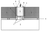
- FIG. 1 is a schematic view showing a first embodiment of a cross section of the structure of the present invention.
- the first member 1 and the second member 2 are overlapped, and a gap 4 is formed between them.
- the interval ⁇ of the clearance 4 is 1 ⁇ m or more and 0.1 mm or less, and most of them are about 10 ⁇ m.
- the gap 4 is filled with an aqueous liquid containing at least Cl - and dissolved oxygen.
- the first member 1 and the second member 2 are opaque.
- the first member 1 can be a metal material
- the second member 2 can be a metal material or a non-metal material.
- the first member 1 is suitable for application of the present invention because crevice corrosion is likely to occur when it is a metal material containing chromium or titanium that is easily passivated.
- a transparent crevice corrosion detector 5 extending from the outside in the direction of the second member 2 up to the gap 4 is inserted.
- a pH indicator 6 is applied to the tip of the crevice corrosion detector 5 facing the gap.
- the fluctuation in pH generated in the gap 4 is caused by the occurrence of corrosion in the first member 1 facing the gap 4 and the second member 2 made of metal in the aqueous liquid present in the gap 4. It occurs with the elution of ions.
- the crevice corrosion detector 5 is transparent, and the change in the hue of the pH indicator 6 can be visually recognized from the outside indicated by the arrows in the figure, so that the environment of the first member 1 and the second member 2 and the clearance 4 caused thereby is destroyed. No change in crevice corrosion can be easily grasped.
- Dissolved oxygen in the aqueous liquid in the gap 4 between the first member 1 and the second member 2 is consumed in a short time, and the potential of the wetted part of the first member 1 in the gap 4 drops, and the anode It becomes.
- dissolved oxygen is constantly supplied to a portion (not shown) in contact with the flowing aqueous liquid in which the first member 1 flows, a high potential is maintained and a reduction reaction proceeds to serve as a cathode. From the portion in contact with the gap 4 of the first member 1 serving as the anode, the metal ion M z + is gradually eluted into the aqueous liquid. When the metal ion concentration increases, the pH in the clearance 4 is gradually lowered by a hydrolysis reaction.
- the aqueous liquid in the clearance 4 since the aqueous liquid in the clearance 4 has a low pH, it becomes highly corrosive.
- the aqueous liquid having a low pH diffuses to the region of the pH indicator 6 applied to the tip of the crevice corrosion detector 5 facing the gap 4 and changes the hue of the pH indicator 6.
- the pH indicator 6 is not particularly limited as long as it is a reagent whose hue changes according to the pH of the aqueous liquid present in the gap 4, but since crevice corrosion occurs in the acidic region, the reagent has a high color tone response to the pH in the acidic region.
- a pH indicator with remarkable discoloration that can enable observation with the naked eye without using a special observation device such as a fluorescence microscope is preferable.
- pH indicators such as ethyl violet, methyl violet, methyl red, bromophenol blue, bromocresol green, and phenolphthalein can be suitably used.
- the crevice corrosion detector 5 is made of a transparent oxygen-impermeable and corrosion-resistant nonmetallic material.
- a weather resistant plastic having durability against vibration and thermal expansion is preferable.
- transparent plastic or glass such as acrylic resin or polycarbonate resin is suitable.
- a known coating method in which a reagent is applied to a transparent plastic or glass surface can be used.
- a sol-gel method in which a mixed solution containing tetraethoxysilane, ethanol, dilute sulfuric acid and a pH indicator is dropped onto a transparent plastic or glass surface and dried to form an organopolysiloxane layer containing the pH indicator (Non-Patent Document) 1 etc.) can be preferably used.
- an organopolysiloxane layer may be formed on a transparent plastic or glass surface, and then a mixed solution containing tetraethoxysilane, ethanol, dilute sulfuric acid and a pH indicator may be dropped and dried.
- an organopolysiloxane layer As a method for forming an organopolysiloxane layer on the surface of a transparent plastic such as polycarbonate, a method of applying a mixture of an alkoxysilane containing no amino group and an alkoxysilane containing an amino group (Patent Document 5, etc.) It is preferable because an organopolysiloxane layer having excellent surface properties such as transparency, high hardness, and scratch resistance can be formed without requiring a primer or the like and having excellent adhesion to a plastic surface.
- the gap d between the crevice corrosion detector 5 and the metal second member 2 is very narrow, and when the aqueous liquid does not flow, the crevice corrosion detector 5 Crevice corrosion occurs between the second member 2 and the second member 2.
- the crevice corrosion occurring between the crevice corrosion detector 5 and the second member 2 is generated and progresses in preference to the crevice corrosion generated in the gap 4 between the first member 1 and the second member 2.
- the crevice corrosion detector 5 and the second member 2 are filled with a sealant, an adhesive, or the like to eliminate the gap, and the water-based liquid is removed from the crevice corrosion detector 5 and the second member 2. Do not flow in between.
- the distance d between the crevice corrosion detector 5 and the second member 2 made of metal is preferably larger than the gap ⁇ between the first member 1 and the second member 2.
- d is preferably about 0.1 mm to 1.0 mm.
- the distance d ′ 0.1 mm to 1.0 mm between the front end surface of the crevice corrosion detector 5 and the front end surface of the first member 1. It is preferable to install in a direction away from the second member 2, that is, a position retracted in the external direction.
- the front end surface of the crevice corrosion detector 5 may be provided flush with the front end surface of the first member 1.
- the thickness of the layer containing the pH indicator is preferably 0.1 ⁇ m to 10 ⁇ m. More preferably, the thickness of the layer containing the pH indicator is 0.5 ⁇ m to 5 ⁇ m. By doing so, it becomes possible to grasp the state of crevice corrosion more quickly and more accurately.
- the fastening between the crevice corrosion detector 5 and the first member 1 may be made by filling with an adhesive or a sealant 8 as shown in FIG.
- an adhesive or a sealant 8 As shown in FIG.
- the crevice corrosion detector 5 When the crevice corrosion detector 5 is made of glass, it may be welded to the first member 1. Since the adhesive and the sealant can also prevent the water-based liquid from entering between the crevice corrosion detector 5 and the first member 1, it is possible to grasp the state of crevice corrosion more accurately.
- a hydrophobic adhesive such as an epoxy-based adhesive, a silicon-based adhesive, a cyanoacrylate-based adhesive, and a urethane-based adhesive is suitable.
- FIG. 3 shows a state in which the crevice corrosion detector 5 is mechanically fastened to the first member 1 in addition to the adhesive and the sealant 8.
- the first member 1 is provided with a female screw groove 9 from the outside toward the gap 4.
- the crevice corrosion detector 5 is provided with a male screw groove 9 ′ so as to be fitted into the female screw groove 9 of the first member 1.
- An adhesive or sealant 8 is applied between the female screw groove 9 and the male screw groove 9 'to prevent the water-based liquid from entering the fastening portion.
- FIG. 4 shows a case where the crevice corrosion detector 5 has a shape having a widened upper portion 5a supported by the first member 1 and a narrower lower portion 5b that provides a gap d2 between the first member 1.
- the structure is shown.
- the first member 1 is provided with a seat portion 1a that receives and supports the crevice corrosion detector 5, and an O-ring groove 10 is provided in the seat portion 1a.
- the first member 1 is provided with a female screw groove 9 in an upper portion 1b fastened to the widened upper portion 5a of the crevice corrosion detector 5, and a male screw groove provided in the widened upper portion 5a of the crevice corrosion detector 5. Mates with 9 '.
- the distance L from the seat portion 1a of the first member 1 to the tip surface is too long, the distance d2 between the first member 1 and the first member 1 formed around the narrow lower portion 5b of the crevice corrosion detector 5 is large.
- a liquid pool containing a large amount of dissolved oxygen can be formed, and an oxygen supply source for supplying dissolved oxygen to the aqueous liquid in the gap 4 will be obtained. Therefore, the distance L is made as short as possible, and the volume into which the aqueous liquid enters is reduced. It is preferable to do. Specifically, a range of 0.1 mm to 1 mm is preferable.
- the lower part of the first member 1 that receives the narrow lower part 5b and the narrow lower part 5b of the crevice corrosion detector 5 is both cylindrical so that the distance d2 is the same distance around the crevice corrosion detector 5. It is preferable that
- the lower surface of the widened upper portion 5a of the crevice corrosion detector 5 is a seal surface that presses and seals the O-ring fitted in the O-ring groove 10 of the seat portion 1a of the first member 1.
- a pH indicator 6 is applied to the front end surface of the narrow lower portion 5 b of the crevice corrosion detector 5.
- the front end surface of the crevice corrosion detector 5 is installed at a position separated from the second member 2 by a distance d1.
- the gap d2 between the crevice corrosion detector 5 and the first member 1 is larger than the gap ⁇ of the gap 4 between the first member 1 and the second member 2, specifically 0.1 mm. About 1.0 mm is preferable.
- the crevice corrosion detector is set so that the distance d1 between the crevice corrosion detector 5 and the second member 2 is 0.1 mm to 1.0 mm. As described with respect to the distance d ′ in FIG. 1, it is preferable to position the front end surface of 5 by retreating from the front end surface of the first member 1 by about 0.1 mm to 1.0 mm.
- FIG. 5 is a mode in which the top and bottom of the crevice corrosion detector 5 are reversed from the mode shown in FIG.
- the crevice corrosion detector 5 has a narrow upper portion 5c and a widened lower portion 5d, and a pH indicator 6 is applied to the tip surface of the widened lower portion 5d.
- the lower portion of the first member 1 is counterbored so as to receive the widened lower portion 5d of the crevice corrosion detector 5, and a seat portion 1a that is in contact with the upper surface of the widened lower portion 5d of the crevice corrosion detector 5 is provided. Is provided with an O-ring groove 10.
- the first member 1 is provided with a female screw groove 9 in an upper portion 1b fastened to a narrow upper portion 5c of the crevice corrosion detector 5, and a male screw provided in the narrow upper portion 5c of the crevice corrosion detector 5. Fits into the thread groove 9 '.
- the distances d1 and d2 between the crevice corrosion detector 5 and the first member 1 and the second member 2 and the distance L between the front end surface of the first member 1 and the seat portion 1a are as described with reference to FIG. .
- FIG. 6A and 6 (B) are explanatory views showing the problem of the aspect in which the second member 2 is an elastic body of a non-metallic material such as rubber packing.
- the second member 2 is an elastic body
- the tip surface of the crevice corrosion detector 5 is retracted from the first member 1 (FIG. 6A)
- the second member 2 is 1 enters the space between the first member 1 and the front end surface of the crevice corrosion detector 5, and a portion 7 a where the clearance 4 between the first member 1 and the second member 2 becomes narrow is formed in the vicinity of the crevice corrosion detector 5. Is done.
- the crevice corrosion detector 5 it is grasped that the crevice corrosion has progressed more than the degree of corrosion in the original crevice 4.
- the crevice corrosion detector 5 is By pressing the member 2, a portion 7 b where the clearance 4 between the first member 1 and the second member 2 becomes wide is formed in the vicinity of the clearance corrosion detector 5. The distance between the two members 2 is reduced. In this case, in the vicinity of the crevice corrosion detector 5, it is grasped that the crevice corrosion is not progressing more than the degree of corrosion in the original crevice 4.
- FIG. 7 shows an embodiment of the present invention applied when the second member 2 is an elastic body.
- a recess 12 is formed at the tip of the crevice corrosion detector 5, and the pH indicator is applied to the surface of the recess 12.
- the outer edge 13 of the recess 12 is provided with crests and troughs at equal intervals so that the aqueous liquid in the gap 4 can contact the pH indicator 6 through the troughs.
- the height of the crest portion of the outer edge 13 is a dimension that can maintain the distance ⁇ between the first member 1 and the second member 2, that is, the distance d or d 'shown in FIG.
- the outer edge 13 at the tip of the crevice corrosion detector 5 can reduce the influence of elastic deformation of the second member 2.
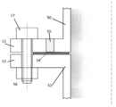
- FIG. 8 shows an embodiment in which the structure of the present invention is a flange.
- the pipe 50 and the pipe 51 are fitted with the seal member 54 between the flanges 52 and 53 and fastened by the fastening members 56 and 57.
- Such piping connection is also used for piping connection with devices such as pumps.
- a gap is formed between the seal members 54 between the flanges 52 and 53. This clearance is even a minute gap depending on the fastening force of the fastening members 56 and 57.
- the flanges 52 and 53 are metal, crevice corrosion may occur in a minute gap between the flanges 52 and 53.
- a crevice corrosion detector 55 is inserted into the flange 52 through the flange 52.
- the configuration of the crevice corrosion detector 55 and the mode of fastening to the flange 52 may be any mode described with reference to FIGS. Since the crevice corrosion detector 55 is a transparent member and is disposed through the flange 52, the color tone change of the pH indicator at the tip of the crevice corrosion detector 55 can be visually recognized from the outside of the flange 52. .
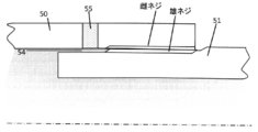
- FIG. 9 shows an embodiment in which the structure of the present invention is configured by fastening two types of pipes.
- a female screw is cut inside the pipe 50, a male screw is cut on the outer periphery of the pipe 51, and both pipes are fastened by these screws.
- a PTFE (polytetrafluoroethylene) seal tape is wound around the male screw in advance before fastening, and when the male screw is screwed into the female screw, the seal tape extends to seal the gap.
- a clearance 54 is formed in such a screw seal portion. Since the pipes 50 and 51 are made of metal, crevice corrosion may occur in a minute gap in the screw seal portion.
- a crevice corrosion detector 55 is inserted through the pipe 50. Since the crevice corrosion detector 55 is a transparent member and is disposed through the pipe 50, a change in the color tone of the pH indicator at the tip of the crevice corrosion detector 55 can be visually recognized from the outside of the pipe 50. .
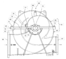
- FIG. 10 shows an example of a double suction centrifugal pump that can be provided with the structure of the present invention as a flange.
- FIG. 10 is an example of a known double suction centrifugal pump disclosed in Japanese Patent Application Laid-Open No. 2010-216470, and is shown for explaining a joint surface in which the structure of the present invention can be incorporated.
- the casings 61 of both suction centrifugal pumps 60 are formed by joining the upper casing body 64 and the lower casing body 65 with the joint surfaces 62 and 63 as a boundary.
- the lower casing body 65 includes a suction port 66 and a discharge port. 67 is formed.
- the suction port 66 has a flange shape as shown in the figure, and a pipe for supplying water on the suction side to the both suction vortex pumps 60 is connected thereto. Further, the discharge port 67 is also in a flange shape, and a pipe for supplying the water on the suction side to the outside from the both suction centrifugal pumps 60 is connected thereto.
- a casing 61 which is a combined body of the upper casing body 64 and the lower casing body 65, is provided with a pair of left and right shaft through holes through which the main shaft 68 penetrates. Is connected.
- the main shaft 68 is connected to a driving device such as a motor (not shown) provided outside the casing 61 and is driven to rotate, whereby the impeller rotates.
- the water supplied from the suction port 66 is guided to the impeller in the casing 61 and pressurized by the rotating action of the impeller.
- the pressurized water is guided from the impeller to the discharge port 67 in the casing 61 and discharged out of the casing 61.
- the upper casing body 64 has an upper flange portion 69 and an upper joint surface 63 at the lower end.
- the lower casing body 65 has a lower flange portion 70 and a lower joint surface 62 at the upper end.
- the upper casing body 64 and the lower casing body 65 are connected to each other by a plurality of bolts 71 (an example of connecting means) with the joint surfaces 62 and 63 joined together.
- the joint surfaces of the flanges connected to the pipes between the joint surfaces 62 and 63 and the suction port 66 and the discharge port 67 are sealed with a sealing member such as a sheet-like gasket, or a seal groove is formed in the lower joint surface 62. It is formed or sealed by fitting a seal member such as a string-like O-ring into the seal groove.
- a sealing member such as a sheet-like gasket, or a seal groove is formed in the lower joint surface 62. It is formed or sealed by fitting a seal member such as a string-like O-ring into the seal groove.
- the crevice corrosion detector (not shown) is formed in a portion where the suction port 66 and the discharge port 67 are connected to the pipe, a portion where the joint surfaces 62 and 63 of the upper and lower casing bodies are joined, and the like as shown in FIG. For example, and may be fastened in the manner shown in FIGS.
Landscapes
- Life Sciences & Earth Sciences (AREA)
- Biodiversity & Conservation Biology (AREA)
- Ecology (AREA)
- Environmental & Geological Engineering (AREA)
- Environmental Sciences (AREA)
- Physics & Mathematics (AREA)
- Health & Medical Sciences (AREA)
- Chemical & Material Sciences (AREA)
- Analytical Chemistry (AREA)
- Biochemistry (AREA)
- General Health & Medical Sciences (AREA)
- General Physics & Mathematics (AREA)
- Immunology (AREA)
- Pathology (AREA)
- Testing Resistance To Weather, Investigating Materials By Mechanical Methods (AREA)
Abstract
実際に稼働しているポンプおよび配管の個々の接合部分において、構造物を分解せずに、すきま腐食に至る環境の進行状況、あるいはすきま腐食の進行状況を簡便に検知する検知方法および当該検知方法を実施できるすきま腐食検知器を具備する構造物を提供する。 金属製の第1の部材1と、第1の部材と同種又は異種の材料からなる第2の部材2とを接合する部位に形成されるすきま4に生じるすきま腐食を検知するすきま腐食検知器5を組み込んだ構造物であって、すきま腐食検知器5は、第2の部材2の方向に向かって、第1の部材1を貫通して設けられており、第1の部材1の外面側から視認可能な透明な部材であり、すきまに面する先端部にpH指示薬を含む。
Description
本発明は、同種又は異種の材料からなる2つの部材が接合する部位に形成されるすきまに生じるすきま腐食を検知するすきま腐食検知器を組み込んだ構造物に関する。
各種金属材料を構成部材とする構造物は、構造設計上及び/又は使用環境上、構成部材同士の接合部位に微小なすきまを有する。異種の金属材料の接合部位は言うに及ばず、同種の金属材料であっても、重ね合わせ部、例えば、ボルトとナットの締結部分、あるいは、金属と非金属の重ね合わせ部、例えばパッキンのようなゴムと金属の合わせ目、また、スケール、錆、微生物などが金属材料に付着する部分、塗装又はライニング被覆材が金属材料から剥離した部分などの部材間の微小なすきまに電位差が生じることによってすきま腐食が発生する。
図11は、すきま腐食の発生メカニズムを説明するための模式図である。金属製の第1の部材1と、第2の部材2が重ね合わさった状態で、水や海水などの水系液体3と接液している。第2の部材2は、第1の部材1と同種又は異種の材料でよく、金属でも非金属でもどちらでも良い。第1の部材1と第2の部材2との間には、微小なすきま4がある。すきま4の間隔δは、大きくても0.1mm程度である。間隔δは、第1の部材1と第2の部材2との合わせ面の表面仕上げの程度により、また、合わせ面の部位により異なっているが、10μm以下のものがほとんどである。
微小なすきま4におけるすきま腐食の発生及び成長メカニズムについて説明する。
(1)非常に微細なすきま4の内部の水系液体は、すきま4の外部の水系液体と容易には交換されないので、水系液体中の溶存酸素が短時間で消費され、すきま4における第1の部材1の接液部分の電位が降下する。一方、すきま4とは異なる第1の部材1における接液部分、例えば配管内壁(図中破線で囲んだ部分B)は、他の部材との距離が大きく、水系液体が流動して溶存酸素の供給が常時行われるので高い電位を維持する。したがって、溶存酸素の供給が常時行われる第1の部材1と液体が接する接液部分表面では還元反応が進むため、当該接液部分はカソードとなるが、すきま4に面する第1の部材1の接液部分は還元反応が進まないためアノードとなり、金属イオンMz+(zは金属Mのイオン価数を示す)が徐々に水系液体中に溶出する。水系液体中の電流は主としてCl-が担うので、すきま内では金属イオンM2+濃度とともに、Cl-濃度が次第に上昇する。金属イオンは、金属イオンMz+濃度が上昇するにつれ、加水分解反応によりすきま内のpHを徐々に低下させる。このようにして、すきま4内の水系液体は、Cl-濃度が高く、pHが低くなるので、腐食性の高い雰囲気となる。
(1)非常に微細なすきま4の内部の水系液体は、すきま4の外部の水系液体と容易には交換されないので、水系液体中の溶存酸素が短時間で消費され、すきま4における第1の部材1の接液部分の電位が降下する。一方、すきま4とは異なる第1の部材1における接液部分、例えば配管内壁(図中破線で囲んだ部分B)は、他の部材との距離が大きく、水系液体が流動して溶存酸素の供給が常時行われるので高い電位を維持する。したがって、溶存酸素の供給が常時行われる第1の部材1と液体が接する接液部分表面では還元反応が進むため、当該接液部分はカソードとなるが、すきま4に面する第1の部材1の接液部分は還元反応が進まないためアノードとなり、金属イオンMz+(zは金属Mのイオン価数を示す)が徐々に水系液体中に溶出する。水系液体中の電流は主としてCl-が担うので、すきま内では金属イオンM2+濃度とともに、Cl-濃度が次第に上昇する。金属イオンは、金属イオンMz+濃度が上昇するにつれ、加水分解反応によりすきま内のpHを徐々に低下させる。このようにして、すきま4内の水系液体は、Cl-濃度が高く、pHが低くなるので、腐食性の高い雰囲気となる。
第1の部材1と第2の部材2との間隔δが小さいほど電位差が生じやすく、すきま腐食が発生しやすい。また、第1の部材1と第2の部材2との間隔δが小さい状況では、すきま4内の水系液体が、すきま4の外部の配管内を流動する水系液体と交換されにくく、第1の部材1を構成する金属からすきま4内の水系液体中にCl-などの腐食性のイオンが濃縮しやすく、すきま腐食が発生しやすい。
(2)すきま4内の水系液体が腐食性の高い状態になると、第1の部材1の接液部分は不動態皮膜を維持できなくなり、図11中Aで示す部分のように活性面が現れ、活性態-不動態電池が形成され、すきま腐食が成長する。この不動態皮膜が破壊され、すきま腐食が成長を始める際の水系液体のpHは、金属材料により異なるが、不動態皮膜が維持されている間のpHとは異なることが知られており、pHを測定することによって、すきま腐食の検出が可能であることが報告されている(非特許文献1)。
ところで、上水、下水、雨水、排水、海水など様々な水を流動させるポンプ及びそれに接続する配管は、上記のような金属材料と接続して合わせ面をなす構造を非常に多く有するため、すきま腐食が生じやすい。例えばフランジ部がボルト及びナットによって接続されている配管において、金属製のフランジ間に挟んで漏水防止用に使われるパッキンと金属製フランジとの間に狭小なすきまが生じるため、そこに入り込む水により、時間経過に伴ってすきま腐食が発生する場合がある。
すきま腐食が進行すると、やがては腐食箇所からの漏水などを誘因する可能性がある。すきま腐食を防止する対策としては、すきま充填剤などによってすきま内への液体の浸入を防止する対応、あるいは犠牲陽極によって腐食の進行を防止する対応などがなされている。
実際に稼働しているポンプおよび配管において、すきま腐食の発生を推定する方法として下記のような提案がなされている。
実際に稼働しているポンプおよび配管を模した状況で実験を行い、その結果から実際に稼働しているポンプおよび配管の状況を推定する方法が提案されている(特許文献1および2)。特許文献1は、モニタリング対象と同じ材料からなり、溶接部、すきま部及び電熱部を有する試験片を提案する。特許文献2は、局部腐食モニタリング用模擬電極を用いて、最大の局部腐食速度及び腐食孔深さをモニタリングする方法を提案する。しかし、これらの推定方法は、配管内を流動する液体の状況は反映するものの、未だに、そのほかの実機特有の条件は再現できず、すきま腐食が起きる環境がどの部分でどの程度進行するのか、構造部材間ですきま腐食が進んでいるのか、などの個別のすきま腐食の推定には限界がある。このため、実際に稼働しているポンプおよび配管の個々の接合部分におけるすきま腐食の発生および進行の程度に関しては、メンテナンス時や補修時などに、装置の運転を停止して、接合部分を取り外して分解しなければ確認することができず、その確認のためには多くの時間や手間を要している。したがって、実際に稼働しているポンプおよび配管の個々の接合部分におけるすきま腐食の発生および進行を模擬的にではなく、実機の個々の接合部分において、簡単に把握する技術が求められている。
水系媒体に接する金属部材の局部腐食をモニターする技術として、水系媒体と小孔を介して連通する凹穴状の液溜部と、液溜部内の液と接するアノード電極と、水系媒体と接するカソード電極と、水系媒体に接する参照電極と、電流計と、参照電極とアノード電極との間の電位差を目的値に維持する電圧印加手段と、を備える装置及び方法が提案されている(特許文献3及び4)。しかし、電極、電流計及び電圧印加装置を配管に設置する必要があり、複雑な構造物において設置することが難しい場合もあり、簡易な方法とはいえない。
サブμm~数十μm程度のすきま内にある液体のpHやCl-濃度を簡易に判定する方法として、すきま腐食が発生すると、すきま内にある液体のpHが低下し、Cl-濃度は上昇するため、pHやCl-濃度の変化により色相が変化する指示薬を透明なガラスプレートの一面に塗布し、その塗布した面と金属板面を重ね合わせて、両者の合わせ面のすきまで生じるpHの低下やCl-濃度の増加の変化を、塗布した指示薬の色相の変化として透明なガラスプレートを通して観察することができたことが報告されている(非特許文献1)。この方法は、透明なガラスプレートを通して、ガラスプレートと金属板の合わせ面に生ずるすきま腐食の状況を観察することができるため簡便である。しかし、実機の個々の構成部材の接合部分、例えばフランジの場合には、不透明な金属材料からなるフランジ同士、あるいはゴム製パッキンがフランジ間に挟持されている。不透明な金属材料のフランジと非金属材料のゴムパッキンにより合わせ面が形成されているので、合わせ面自体はどの方向からも観察できず、またガラスプレートを通して視認するというそのままの技術の利用は困難である。
T.Kaji et al, J.Electrochem.Soc.,159(7)C289-C297(2012)
本発明は、実際に稼働しているポンプおよび配管の個々の接合部分において、構造物を分解せずに、すきま腐食に至る環境の進行状況、あるいはすきま腐食の進行状況を簡便に検知する検知方法および当該検知方法を実施できるすきま腐食検知器を具備する構造物を提供することを目的とする。
本発明によれば、金属製の第1の部材と、当該第1の部材と同種又は異種の材料からなる第2の部材とを接合する部位に形成されるすきまに生じるすきま腐食を検知するすきま腐食検知器を組み込んだ構造物であって、当該すきま腐食検知器は、当該第2の部材の方向に向かって、当該第1の部材を貫通して設けられており、当該第1の部材の外面側から視認可能な透明な部材であり、当該すきまに面する先端部にpH指示薬を含む、構造物が提供される。
前記すきま腐食検知器は、接着剤、シール部材、Oリング又は締結手段を介して前記第1の部材に取り付けられている構造物であってもよい。
前記すきま腐食検知器は、前記第1の部材との間に前記すきまよりも大きな間隔を有して設けられていることが好ましい。
前記すきま腐食検知器は、前記第2の部材との間に前記すきまよりも大きな間隔を有して設けられていることが好ましい。
前記間隔は、0.1mm~1.0mmの範囲であることが好ましい。
前記構造物は、水配管に連結されたフランジ、又は水ポンプのケーシングのフランジであってもよい。
また、本発明によれば、上記構造物を有する流体機械も提供される。
前記すきま腐食検知器は、接着剤、シール部材、Oリング又は締結手段を介して前記第1の部材に取り付けられている構造物であってもよい。
前記すきま腐食検知器は、前記第1の部材との間に前記すきまよりも大きな間隔を有して設けられていることが好ましい。
前記すきま腐食検知器は、前記第2の部材との間に前記すきまよりも大きな間隔を有して設けられていることが好ましい。
前記間隔は、0.1mm~1.0mmの範囲であることが好ましい。
前記構造物は、水配管に連結されたフランジ、又は水ポンプのケーシングのフランジであってもよい。
また、本発明によれば、上記構造物を有する流体機械も提供される。
本発明の構造物は、すきま腐食が進行しやすいポンプおよび配管の個々の接合部分を分解せずに、容易にすきま内の水系液体のpHをモニタリングすることができ、すきま腐食の発生および進行を視認することができる。
従来の測定技術やモニタリング技術では、大がかりで精密な測定機器や計算機器などの装置が必要であったのに比べ、本発明のすきま腐食検知器を組み込んだ構造物をポンプおよび配管として簡易に採用することができ、ポンプおよび配管の個々の接合部分におけるすきま腐食を容易に検知することができる。
また、使用水の変動、締め付けトルクの違いや、表面粗さなどの表面仕上げの違い(材料表面形状の違い)などのすきま条件の違いがあるにもかかわらず、実際に稼働しているポンプおよび配管の個々の接合部分の状況を直接的に観測できるので、従来の代表的な条件の模擬的な予想に比べて、実機の個々の接合部分の正確な状況把握が行える。
本発明のすきま腐食検知器を具備する構造物は、当該構造物を組み込んだ設備の運転を停止することなく、構造物内のすきま腐食を早期に正確に発見できるため、設備のメンテナンス性が向上し、さらにダウンタイムも低減できる。
以下、添付図面を参照しながら本発明を詳細に説明するが、本発明はこれらに限定されるものではない。なお、添付図面は、部材間のすきまを説明するために、すきまのみを拡大して示している。実際のすきまの寸法は10μm以下と極めて微細であり、第1の部材、第2の部材および配管は数mm~数mにも及び、部材の縮尺が正しくないことに注意されたい。
図1~図5は、第1の部材1と、第2の部材2と、両者の間のすきま4内で生じるすきま腐食の進行状況を把握するためのすきま腐食検知器5と、の位置関係及び締結態様を説明する。図1~図5の説明において、同じ部材、構成及び締結態様についての説明は繰り返さないが、適宜組み合わせが可能である。
図1は本発明の構造物の断面の第一の態様を示す模式図である。第1の部材1及び第2の部材2が重ね合わせられて、両者の間にはすきま4が形成されている。すきま4の間隔δは1μm以上0.1mm以下、ほとんどのものは10μm程度である。このすきま4に、少なくともCl-と溶存酸素を含む水系液体が満たされている。第1の部材1および第2の部材2は不透明である。第1の部材1は金属材料であり、第2の部材2は金属材料の場合も非金属材料の場合もありうる。第1の部材1としては、不動態化しやすいクロムやチタンを含む金属材料である場合にすきま腐食を生じやすいため、本発明の適用に好適である。
第1の部材1には、外部から第2の部材2の方向に、すきま4にまで至る透明なすきま腐食検知器5が挿入されている。すきま腐食検知器5のすきまに面する先端部には、pH指示薬6が塗布されている。すきま4で生じるpHの変動は、すきま4内に存在する水系液体中に、すきま4に面する第1の部材1、および金属製である第2の部材2における腐食の発生および進行に伴う金属イオンの溶出に伴い生じるものである。すきま腐食検知器5は透明で、pH指示薬6の色相の変化は、図中矢印で示す外部から視認できるため、第1の部材1および第2の部材2とそれによるすきま4の環境を壊すことなく、すきま腐食の状況変化を容易に把握できる。
第1の部材1と第2の部材2との間のすきま4の水系液体中の溶存酸素は短時間で消費され、すきま4における第1の部材1の接液部分の電位が降下し、アノードとなる。一方、第1の部材1が流動する水系液体と接液する部分(図示せず)には溶存酸素が常時供給されるため、高い電位が維持され、還元反応が進行するためカソードとなる。アノードとなった第1の部材1のすきま4との接液部分からは、金属イオンMz+が徐々に水系液体中に溶出する。金属イオン濃度が上昇すると加水分解反応によりすきま4内のpHを徐々に低下させる。このようにして、すきま4内の水系液体は低pHとなるので、腐食性の高い状態になる。低pHとなった水系液体は、すきま4に面するすきま腐食検知器5の先端部に塗布されたpH指示薬6の領域にまで拡散し、pH指示薬6の色相を変化させる。
pH指示薬6は、すきま4に存在する水系液体のpHに応じて色相が変化する試薬であれば特に限定されないが、すきま腐食が酸性領域で生じることから酸性領域のpHに対する色調応答性が高い試薬が好ましく、特に、蛍光顕微鏡などの特別な観察装置を用いることなく、その場での肉眼による観察を可能とすることができる変色性の顕著なpH指示薬が好ましい。たとえば、エチルバイオレット、メチルバイオレット、メチルレッド、ブロモフェノールブルー、ブロモクレゾールグリーン、フェノールフタレインなどのpH指示薬を好適に用いることができる。
すきま腐食検知器5は、透明な酸素不透過性かつ耐食性の非金属材料から構成される。すきま腐食検知器5を組み込む構造物が海水接触構造物である場合には、振動や熱膨張に対する耐久性を具備する耐候性プラスチックなどが好ましい。具体的には、アクリル樹脂、ポリカーボネート樹脂などの透明なプラスチックやガラスが好適である。
すきま腐食検知器5の先端部にpH指示薬を適用する方法は、透明なプラスチックやガラス表面に試薬を塗布する公知のコーティング方法を用いることができる。例えば、透明なプラスチックやガラス表面に、テトラエトキシシラン、エタノール、希硫酸及びpH指示薬を含む混合溶液を滴下して乾燥させ、pH指示薬を包含したオルガノポリシロキサン層を形成するゾルゲル法(非特許文献1など)を好適に用いることができる。あるいは、透明なプラスチックやガラス表面に、オルガノポリシロキサン層を形成させ、その後、テトラエトキシシラン、エタノール、希硫酸及びpH指示薬を含む混合溶液を滴下して乾燥させてもよい。ポリカーボネートなどの透明なプラスチック表面に、オルガノポリシロキサン層を成膜させる方法として、アミノ基を含有しないアルコキシシランと、アミノ基を含有するアルコキシシランの混合物を塗布する方法(特許文献5など)は、プライマーなどを必要とせずにプラスチック表面への密着性が非常に良く、透明、高硬度、耐擦傷性などの表面特性に優れたオルガノポリシロキサン層を成膜することができるので好ましい。
第2の部材2が金属である場合には、すきま腐食検知器5と金属である第2の部材2の間隔dが非常に狭く、水系液体が流動しない場合には、すきま腐食検知器5と第2の部材2との間ですきま腐食が生じる。すきま腐食検知器5と第2の部材2との間で生じるすきま腐食が、第1の部材1と第2の部材2のすきま4で生じるすきま腐食よりも優先して発生し進行する虞があり、実際の第1の部材1と第2の部材2のすきま4で生じるすきま腐食の状況を把握できなくなる。かかる場合に備えて、すきま腐食検知器5と第2の部材2との間に、シール剤や接着剤などを充填してすきまをなくし、水系液体がすきま腐食検知器5と第2の部材2との間に流入しないようにする。
第2の部材2とすきま腐食検知器5との間隔dをすきま腐食が生じない程度まで拡幅することも可能である。この場合、間隔dをあまり大きくしすぎると、溶存酸素を多く含む水系液体の液溜まりができてしまう。この液溜まりは、すきま腐食検知器5近傍の第1の部材1と第2の部材2とのすきま4に溶存酸素を供給する酸素供給源となってしまい、やはり正確なすきま腐食の状況の把握が困難になる。また、液溜まりの容積が大きいと、すきま腐食により生成した腐食液が、液溜まり内で希釈されるため、正確なすきま腐食の状況の把握が困難になる。
したがって、すきま腐食検知器5と金属である第2の部材2との間隔dは、第1の部材1と第2の部材2との間のすきまの間隔δよりも大きいことが好ましく、具体的にはd=0.1mm~1.0mm程度とすることが好ましい。第2の部材2とすきま腐食検知器5との間隔を制御するために、すきま腐食検知器5の先端面を第1の部材1の先端面から距離d’=0.1mm~1.0mm程度、第2の部材2から離隔する方向、すなわち外部方向に後退した位置に設置することが好ましい。なお、第2の部材2が非金属材料である場合には、すきま腐食検知器5の先端面は第1の部材1の先端面と面一に設けてもよい。
pH指示薬を含む層の厚みが大きい場合、pH指示薬を含む層がすきま腐食検知器5から剥離するおそれがある。一方、pH指示薬を含む層の厚みが小さい場合には、pH指示薬が溶出しきってしまい、短時間で腐食状況を把握できなくなるおそれがある。そのため、pH指示薬を含む層の厚さは0.1μm~10μmとすることが好ましい。より好ましくは、pH指示薬を含む層の厚みは0.5μm~5μmである。そうすることで、応答が速く、かつ、より正確にすきま腐食の状況の把握ができるようになる。
pH指示薬を含む層の厚みが大きい場合、pH指示薬を含む層がすきま腐食検知器5から剥離するおそれがある。一方、pH指示薬を含む層の厚みが小さい場合には、pH指示薬が溶出しきってしまい、短時間で腐食状況を把握できなくなるおそれがある。そのため、pH指示薬を含む層の厚さは0.1μm~10μmとすることが好ましい。より好ましくは、pH指示薬を含む層の厚みは0.5μm~5μmである。そうすることで、応答が速く、かつ、より正確にすきま腐食の状況の把握ができるようになる。
すきま腐食検知器5と第1の部材1との間の締結は、図2に示すように、接着剤やシール剤8の充填によりなされてもよい。すきま腐食検知器5がガラス製である場合には、第1の部材1と溶接してもよい。接着剤やシール剤は、すきま腐食検知器5と第1の部材1との間に、水系液体が侵入することも防止することができるため、より正確なすきま腐食の状況の把握ができる。接着剤としては、エポキシ系接着剤、シリコン系接着剤、シアノアクリレート系接着剤、ウレタン系接着剤などの疎水性接着剤が好適である。
図3は、接着剤やシール剤8に加えて、すきま腐食検知器5を第1の部材1に機械的に締結した状態を示す。第1の部材1には、外部からすきま4に向かって雌ネジ溝9が設けられている。すきま腐食検知器5には、第1の部材1の雌ネジ溝9に嵌合するように雄ネジ溝9’が設けられている。雌ネジ溝9と雄ネジ溝9’との間には、接着剤又はシール剤8が塗布されており、締結部分への水系液体の侵入を防止する。
図4は、すきま腐食検知器5が、第1の部材1により支持される拡幅上部5aと、第1の部材1との間に間隔d2を設ける狭幅下部5bと、を有する形状である場合の構造物を示す。第1の部材1には、すきま腐食検知器5を受け入れて支持する座部1aが設けられ、座部1aにはOリング溝10が設けられている。さらに、第1の部材1には、すきま腐食検知器5の拡幅上部5aと締結する上部1bに雌ネジ溝9が設けられ、すきま腐食検知器5の拡幅上部5aに設けられている雄ネジ溝9’と嵌合する。
第1の部材1の座部1aから先端面までの距離Lが長すぎると、すきま腐食検知器5の狭幅下部5bの周囲に形成される第1の部材1との間の間隔d2が大きくなり、溶存酸素が多く含まれた液溜まりができ、すきま4内の水系液体に溶存酸素を供給する酸素供給源となってしまうため、距離Lは極力短くし、水系液体の侵入する容積を小さくすることが好ましい。具体的には、0.1mm~1mmの範囲とすることが好ましい。また、間隔d2がすきま腐食検知器5の周囲にわたって同一の距離となるように、すきま腐食検知器5の狭幅下部5b及び狭幅下部5bを受け入れる第1の部材1の下部は、ともに円筒形状であることが好ましい。
すきま腐食検知器5の拡幅上部5aの下面は、第1の部材1の座部1aのOリング溝10に嵌め込まれたOリングを押圧してシールするシール面である。すきま腐食検知器5の狭幅下部5bの先端面には、pH指示薬6が塗布されている。すきま腐食検知器5の先端面は、第2の部材2から間隔d1だけ離間した位置に設置される。
すきま腐食検知器5と第1の部材1との間の間隔d2は、第1の部材1と第2の部材2との間のすきま4の間隔δよりも大きく、具体的には0.1mm~1.0mm程度が好適である。なお、第2の部材2が金属製である場合には、すきま腐食検知器5と第2の部材2との間の間隔d1=0.1mm~1.0mmとなるように、すきま腐食検知器5の先端面を第1の部材1の先端面より0.1mm~1.0mm程度後退させて位置づけることが好ましいことは図1の間隔d’に関して説明したとおりである。
図5は、図4に示した態様とすきま腐食検知器5の上下が逆の態様である。すきま腐食検知器5は、狭幅上部5cと拡幅下部5dとを有し、拡幅下部5dの先端面にはpH指示薬6が塗布されている。第1の部材1の下部は、すきま腐食検知器5の拡幅下部5dを受け入れるようにザグリされており、すきま腐食検知器5の拡幅下部5dの上面と接する座部1aが設けられ、座部1aにはOリング溝10が設けられている。さらに、第1の部材1には、すきま腐食検知器5の狭幅上部5cと締結する上部1bに雌ネジ溝9が設けられ、すきま腐食検知器5の狭幅上部5cに設けられている雄ネジ溝9’と嵌合する。すきま腐食検知器5と第1の部材1及び第2の部材2との間隔d1及びd2並びに第1の部材1の先端面と座部1aとの距離Lは、図4に関して説明したとおりである。
図6(A)及び(B)は、第2の部材2がゴム製パッキンなどの非金属材料の弾性体である態様の問題点を示す説明図である。第2の部材2が弾性体である場合、すきま腐食検知器5の先端面が第1の部材1よりも後退している場合(図6(A))には、第2の部材2が第1の部材1とすきま腐食検知器5の先端面との間のスペースに入り込み、すきま腐食検知器5近傍に第1の部材1と第2の部材2とのすきま4が狭くなる部分7aが形成される。この場合、すきま腐食検知器5の近傍では、すきま腐食が本来のすきま4における腐食程度よりも進行した状況として把握される。
逆に、すきま腐食検知器5の先端部が第1の部材1よりも第2の部材2に向かって突出している場合(図6(B))には、すきま腐食検知器5が第2の部材2を押圧して、すきま腐食検知器5近傍に第1の部材1と第2の部材2とのすきま4が広くなる部分7bが形成され、一方ですきま腐食検知器5の先端部と第2の部材2との間隔が小さくなる。この場合、すきま腐食検知器5の近傍では、すきま腐食が本来のすきま4における腐食程度よりも進行していない状況として把握される。
図6(A)及び(B)のいずれの態様においても、すきま腐食検知器5近傍では、本来のすきま4とは異なるすきま7a又は7bが形成されるため、すきま腐食の状況を精確に把握できない。
図7は、第2の部材2が弾性体である場合に適用する本発明の実施態様を示す。図7において、すきま腐食検知器5の先端部には、凹部12が形成されており、pH指示薬は凹部12表面に塗布されている。凹部12の外縁13には等間隔に山部と谷部が設けられ、谷部を通ってすきま4内の水系液体がpH指示薬6と接触できるように構成されている。外縁13の山部の高さは、第1の部材1と第2の部材2との間隔δ、すなわち図1に示す間隔d又はd’を維持できる寸法である。すきま腐食検知器5の先端部の外縁13によって、第2の部材2の弾性変形の影響を減少させることができる。
図8は、本発明の構造物がフランジである場合の実施態様を示す。配管50と配管51が、フランジ52、53の間にシール部材54を挟んで合わせられ、締結部材56、57にて締結されている。このような配管接続はポンプなどの機器との配管接続にも用いられる。ここで、フランジ52、53の間にシール部材54の間にすきまができる。このすきまは、締結部材56、57の締結力に依存した微小なすきまである。通常、フランジ52、53は金属であるので、シール部材54との間の微小なすきまにおいて、すきま腐食が生じる恐れがある。
フランジ52には、フランジ52を貫通してすきま腐食検知器55が挿入されている。すきま腐食検知器55の構成及びフランジ52に締結する態様は、図1~5及び7に関して説明したいずれの態様でも良い。すきま腐食検知器55は、透明部材で、フランジ52を貫通して配置されているため、フランジ52の外部側から、すきま腐食検知器55の先端部のpH指示薬の色調変化を視認することができる。
図9は、本発明の構造物が2種の配管の締結により構成される場合の実施態様を示す。配管50の内側に雌ネジが切られ、配管51の外周に雄ネジが切られ、両配管はこれらのネジにより締結されている。雄ネジには締結までに予めPTFE(ポリテトラフルオロエチレン)シールテープが巻きつけられ、雄ネジが雌ネジにねじ込まれる際に、シールテープが伸延してすきまを塞ぎシールする。ここで、このようなネジシール部分にすきま54ができる。配管50、51は金属であるので、ネジシール部分の微小なすきまにおいて、すきま腐食が生じる恐れがある。配管50を貫通してすきま腐食検知器55が挿入されている。すきま腐食検知器55は、透明部材で、配管50を貫通して配置されているため、配管50の外部側から、すきま腐食検知器55の先端部のpH指示薬の色調変化を視認することができる。
図10は、本発明の構造物をフランジとして具備することができる両吸込み渦巻きポンプの一例を示す。なお、図10は特開2010-216470号公報に開示されている公知の両吸込み渦巻きポンプの一例であり、本発明の構造物を組み込むことができる接合面の説明のために示すものであって、本発明はこれに限定されない。両吸込み渦巻きポンプ60のケーシング61は、接合面62、63を境として、上部のケーシング体64と下部のケーシング体65の結合により形成され、下部のケーシング体65には、吸込口66と吐出口67とが形成されている。吸込口66は図示のようにフランジ形状で、そこに、吸込側の水を両吸込み渦巻きポンプ60に送水する配管が接続される。また、吐出口67もフランジ形状で、そこに、吸込側の水を両吸込み渦巻きポンプ60から外部に送水する配管が接続される。上部のケーシング体64と下部のケーシング体65の結合体であるケーシング61には、主軸68が貫通する左右一対の軸貫通孔が設けられ、ケーシング61の内部で、主軸68には図示しない羽根車が接続されている。主軸68はケーシング61外部に設けられた図示しないモータ等の駆動装置に接続され、回転駆動されることにより、羽根車が回転する。吸込口66から供給された水は、ケーシング61内で羽根車に導かれ、羽根車の回転作用により加圧される。加圧された水は、羽根車からケーシング61内で吐出口67に導かれてケーシング61外に吐出される。上部のケーシング体64は、下端部に、上部のフランジ部69と上部の接合面63とを有している。また、下部のケーシング体65は、上端部に、下部のフランジ部70と下部の接合面62とを有している。上部のケーシング体64と下部のケーシング体65とは、互いに接合面62,63同士を接合して、複数のボルト71(連結手段の一例)により連結されている。両接合面62,63間や、吸込口66や吐出口67で配管と接続するフランジの合わせ面は、例えばシート状のガスケット等のシール部材でシールされたり、下部の接合面62にシール溝が形成されたり、シール溝にゴム製で且つ紐状のOリングなどのシール部材を嵌め込むことなどによりシールされている。吸込口66及び吐出口67が配管と接続する部分、上下のケーシング本体の接合面62,63を接合する部分などに、すきま腐食検知器(図示せず)はたとえば図8又は9に示す態様にて組み込まれ、たとえば図1~5及び7に示すような態様にて締結されていてよい。
Claims (7)
- 金属製の第1の部材と、当該第1の部材と同種又は異種の材料からなる第2の部材とを接合する部位に形成されるすきまに生じるすきま腐食を検知するすきま腐食検知器を組み込んだ構造物であって、
当該すきま腐食検知器は、当該第2の部材の方向に向かって、当該第1の部材を貫通して設けられており、当該第1の部材の外面側から視認可能な透明な部材であり、当該すきまに面する先端部にpH指示薬を含む、
構造物。 - 前記すきま腐食検知器は、接着剤、シール部材、Oリング又は締結手段を介して前記第1の部材に取り付けられている、請求項1に記載の構造物。
- 前記すきま腐食検知器は、前記第1の部材との間に前記すきまよりも大きな間隔を有して設けられている、請求項1又は2に記載の構造物。
- 前記すきま腐食検知器は、前記第2の部材との間に前記すきまよりも大きな間隔を有して設けられている、請求項1~3のいずれかに記載の構造物。
- 前記間隔は、0.1mm~1.0mmの範囲である、請求項3又は4に記載の構造物。
- 前記構造物は、水配管に連結されたフランジ、又は水ポンプのケーシングのフランジである、請求項1~5のいずれかに記載の構造物。
- 請求項1~6のいずれか1に記載の構造物を有する流体機械。
Priority Applications (1)
| Application Number | Priority Date | Filing Date | Title |
|---|---|---|---|
| JP2017509415A JPWO2016158146A1 (ja) | 2015-03-27 | 2016-02-29 | すきま腐食検知器を組み込んだ構造物 |
Applications Claiming Priority (2)
| Application Number | Priority Date | Filing Date | Title |
|---|---|---|---|
| JP2015065961 | 2015-03-27 | ||
| JP2015-065961 | 2015-03-27 |
Publications (1)
| Publication Number | Publication Date |
|---|---|
| WO2016158146A1 true WO2016158146A1 (ja) | 2016-10-06 |
Family
ID=57004462
Family Applications (1)
| Application Number | Title | Priority Date | Filing Date |
|---|---|---|---|
| PCT/JP2016/056011 Ceased WO2016158146A1 (ja) | 2015-03-27 | 2016-02-29 | すきま腐食検知器を組み込んだ構造物 |
Country Status (2)
| Country | Link |
|---|---|
| JP (1) | JPWO2016158146A1 (ja) |
| WO (1) | WO2016158146A1 (ja) |
Cited By (1)
| Publication number | Priority date | Publication date | Assignee | Title |
|---|---|---|---|---|
| CN109900579A (zh) * | 2019-04-04 | 2019-06-18 | 中国船舶重工集团公司第七0四研究所 | 实现海水泵叶轮冲刷腐蚀试验装置 |
Citations (4)
| Publication number | Priority date | Publication date | Assignee | Title |
|---|---|---|---|---|
| JPS54130189A (en) * | 1978-03-31 | 1979-10-09 | Toshiba Corp | Gap corrosion test method |
| JPS6292455U (ja) * | 1985-11-30 | 1987-06-12 | ||
| US6536264B1 (en) * | 2002-04-11 | 2003-03-25 | Detroit Diesel Corporation | Apparatus for detecting coolant corrosiveness |
| US20030068824A1 (en) * | 1999-12-21 | 2003-04-10 | Gerald S. Frankel | Corrosion-sensing composition and method of use |
-
2016
- 2016-02-29 WO PCT/JP2016/056011 patent/WO2016158146A1/ja not_active Ceased
- 2016-02-29 JP JP2017509415A patent/JPWO2016158146A1/ja active Pending
Patent Citations (4)
| Publication number | Priority date | Publication date | Assignee | Title |
|---|---|---|---|---|
| JPS54130189A (en) * | 1978-03-31 | 1979-10-09 | Toshiba Corp | Gap corrosion test method |
| JPS6292455U (ja) * | 1985-11-30 | 1987-06-12 | ||
| US20030068824A1 (en) * | 1999-12-21 | 2003-04-10 | Gerald S. Frankel | Corrosion-sensing composition and method of use |
| US6536264B1 (en) * | 2002-04-11 | 2003-03-25 | Detroit Diesel Corporation | Apparatus for detecting coolant corrosiveness |
Non-Patent Citations (1)
| Title |
|---|
| KAJI, T. ET AL.: "Visualization of pH and pCl Distributions: Initiation and Propagation Criteria for Crevice Corrosion of Stainless Steel", VISUALIZATION OF PH AND PCL DISTRIBUTIONS: INITIATIONAND PROPAGATION CRITERIA FOR CREVICE CORROSION OF STAINLESS STEEL, vol. 159, no. 7, 17 July 2012 (2012-07-17), pages C289 - C297, XP055320553 * |
Cited By (2)
| Publication number | Priority date | Publication date | Assignee | Title |
|---|---|---|---|---|
| CN109900579A (zh) * | 2019-04-04 | 2019-06-18 | 中国船舶重工集团公司第七0四研究所 | 实现海水泵叶轮冲刷腐蚀试验装置 |
| CN109900579B (zh) * | 2019-04-04 | 2024-03-01 | 中国船舶重工集团公司第七0四研究所 | 实现海水泵叶轮冲刷腐蚀试验装置 |
Also Published As
| Publication number | Publication date |
|---|---|
| JPWO2016158146A1 (ja) | 2018-01-25 |
Similar Documents
| Publication | Publication Date | Title |
|---|---|---|
| CN205426748U (zh) | 动态腐蚀评价装置 | |
| WO2016158146A1 (ja) | すきま腐食検知器を組み込んだ構造物 | |
| CN211042340U (zh) | 一种喷嘴流量计 | |
| CN1890543A (zh) | 用于测量仪器的管接头及设置有这种管接头的测量探针 | |
| CN218546728U (zh) | 一种应用于苛性固溶液体的pH值在线检测装置 | |
| CN118655067A (zh) | 一种海洋装备腐蚀疲劳耦合加速试验装置及试验方法 | |
| CN215811027U (zh) | 一种具有防渗透功能的双管电磁流量机 | |
| CN104640765A (zh) | 具有双重擦拭器结构的压载水紫外线处理装置 | |
| CN205877496U (zh) | 一种盲板法兰与管道的防腐连接结构 | |
| CN204313894U (zh) | 测量蒸汽流量用管道孔板结构 | |
| CN214741274U (zh) | 一种用于钻井设备的计量装置 | |
| CN205483420U (zh) | 一种复合板设备双层检漏结构 | |
| CN115963237A (zh) | 一种应用于苛性固溶液体的ph值在线检测装置 | |
| CN211145547U (zh) | 一种可以检测液体流速的阀门 | |
| CN207832373U (zh) | 一种测压装置 | |
| CN203385453U (zh) | 防腐型均衡流量计 | |
| CN102022557B (zh) | 对向密封截止阀 | |
| CN210106866U (zh) | 一种内衬设备支管的堵漏专用工装 | |
| CN222336393U (zh) | 一种耐腐蚀双法兰差压变送器 | |
| CN223725727U (zh) | 一种法兰垫片 | |
| CN220649629U (zh) | 一种在线插入式超声流量计 | |
| CN219315128U (zh) | 电解铜箔防氧化槽 | |
| CN216303992U (zh) | 用于核电站阴极保护系统的参比电极校准装置 | |
| CN224216125U (zh) | 一种耐强酸强碱的容积式流量计 | |
| CN205877579U (zh) | 一种防腐盲板法兰 |
Legal Events
| Date | Code | Title | Description |
|---|---|---|---|
| 121 | Ep: the epo has been informed by wipo that ep was designated in this application |
Ref document number: 16772030 Country of ref document: EP Kind code of ref document: A1 |
|
| ENP | Entry into the national phase |
Ref document number: 2017509415 Country of ref document: JP Kind code of ref document: A |
|
| NENP | Non-entry into the national phase |
Ref country code: DE |
|
| 122 | Ep: pct application non-entry in european phase |
Ref document number: 16772030 Country of ref document: EP Kind code of ref document: A1 |