WO2016158143A1 - Injection needle assembly, and drug injection device - Google Patents
Injection needle assembly, and drug injection device Download PDFInfo
- Publication number
- WO2016158143A1 WO2016158143A1 PCT/JP2016/055999 JP2016055999W WO2016158143A1 WO 2016158143 A1 WO2016158143 A1 WO 2016158143A1 JP 2016055999 W JP2016055999 W JP 2016055999W WO 2016158143 A1 WO2016158143 A1 WO 2016158143A1
- Authority
- WO
- WIPO (PCT)
- Prior art keywords
- needle
- main body
- needle tube
- tube
- skin
- Prior art date
Links
Images


Classifications
-
- A—HUMAN NECESSITIES
- A61—MEDICAL OR VETERINARY SCIENCE; HYGIENE
- A61M—DEVICES FOR INTRODUCING MEDIA INTO, OR ONTO, THE BODY; DEVICES FOR TRANSDUCING BODY MEDIA OR FOR TAKING MEDIA FROM THE BODY; DEVICES FOR PRODUCING OR ENDING SLEEP OR STUPOR
- A61M5/00—Devices for bringing media into the body in a subcutaneous, intra-vascular or intramuscular way; Accessories therefor, e.g. filling or cleaning devices, arm-rests
- A61M5/178—Syringes
- A61M5/31—Details
- A61M5/32—Needles; Details of needles pertaining to their connection with syringe or hub; Accessories for bringing the needle into, or holding the needle on, the body; Devices for protection of needles
- A61M5/3205—Apparatus for removing or disposing of used needles or syringes, e.g. containers; Means for protection against accidental injuries from used needles
- A61M5/321—Means for protection against accidental injuries by used needles
- A61M5/322—Retractable needles, i.e. disconnected from and withdrawn into the syringe barrel by the piston
- A61M5/3221—Constructional features thereof, e.g. to improve manipulation or functioning
-
- A—HUMAN NECESSITIES
- A61—MEDICAL OR VETERINARY SCIENCE; HYGIENE
- A61M—DEVICES FOR INTRODUCING MEDIA INTO, OR ONTO, THE BODY; DEVICES FOR TRANSDUCING BODY MEDIA OR FOR TAKING MEDIA FROM THE BODY; DEVICES FOR PRODUCING OR ENDING SLEEP OR STUPOR
- A61M5/00—Devices for bringing media into the body in a subcutaneous, intra-vascular or intramuscular way; Accessories therefor, e.g. filling or cleaning devices, arm-rests
- A61M5/178—Syringes
- A61M5/31—Details
- A61M5/315—Pistons; Piston-rods; Guiding, blocking or restricting the movement of the rod or piston; Appliances on the rod for facilitating dosing ; Dosing mechanisms
- A61M5/31511—Piston or piston-rod constructions, e.g. connection of piston with piston-rod
- A61M5/31515—Connection of piston with piston rod
-
- A—HUMAN NECESSITIES
- A61—MEDICAL OR VETERINARY SCIENCE; HYGIENE
- A61M—DEVICES FOR INTRODUCING MEDIA INTO, OR ONTO, THE BODY; DEVICES FOR TRANSDUCING BODY MEDIA OR FOR TAKING MEDIA FROM THE BODY; DEVICES FOR PRODUCING OR ENDING SLEEP OR STUPOR
- A61M5/00—Devices for bringing media into the body in a subcutaneous, intra-vascular or intramuscular way; Accessories therefor, e.g. filling or cleaning devices, arm-rests
- A61M5/178—Syringes
- A61M5/31—Details
- A61M5/32—Needles; Details of needles pertaining to their connection with syringe or hub; Accessories for bringing the needle into, or holding the needle on, the body; Devices for protection of needles
- A61M5/3205—Apparatus for removing or disposing of used needles or syringes, e.g. containers; Means for protection against accidental injuries from used needles
- A61M5/321—Means for protection against accidental injuries by used needles
- A61M5/322—Retractable needles, i.e. disconnected from and withdrawn into the syringe barrel by the piston
- A61M5/3221—Constructional features thereof, e.g. to improve manipulation or functioning
- A61M2005/3228—Constructional features thereof, e.g. to improve manipulation or functioning the needle being retracted by a member protruding laterally through a slot in the barrel, e.g. double-ended needles
-
- A—HUMAN NECESSITIES
- A61—MEDICAL OR VETERINARY SCIENCE; HYGIENE
- A61M—DEVICES FOR INTRODUCING MEDIA INTO, OR ONTO, THE BODY; DEVICES FOR TRANSDUCING BODY MEDIA OR FOR TAKING MEDIA FROM THE BODY; DEVICES FOR PRODUCING OR ENDING SLEEP OR STUPOR
- A61M2202/00—Special media to be introduced, removed or treated
- A61M2202/04—Liquids
-
- A—HUMAN NECESSITIES
- A61—MEDICAL OR VETERINARY SCIENCE; HYGIENE
- A61M—DEVICES FOR INTRODUCING MEDIA INTO, OR ONTO, THE BODY; DEVICES FOR TRANSDUCING BODY MEDIA OR FOR TAKING MEDIA FROM THE BODY; DEVICES FOR PRODUCING OR ENDING SLEEP OR STUPOR
- A61M5/00—Devices for bringing media into the body in a subcutaneous, intra-vascular or intramuscular way; Accessories therefor, e.g. filling or cleaning devices, arm-rests
- A61M5/178—Syringes
- A61M5/31—Details
- A61M5/315—Pistons; Piston-rods; Guiding, blocking or restricting the movement of the rod or piston; Appliances on the rod for facilitating dosing ; Dosing mechanisms
- A61M5/31511—Piston or piston-rod constructions, e.g. connection of piston with piston-rod
- A61M5/31513—Piston constructions to improve sealing or sliding
-
- A—HUMAN NECESSITIES
- A61—MEDICAL OR VETERINARY SCIENCE; HYGIENE
- A61M—DEVICES FOR INTRODUCING MEDIA INTO, OR ONTO, THE BODY; DEVICES FOR TRANSDUCING BODY MEDIA OR FOR TAKING MEDIA FROM THE BODY; DEVICES FOR PRODUCING OR ENDING SLEEP OR STUPOR
- A61M5/00—Devices for bringing media into the body in a subcutaneous, intra-vascular or intramuscular way; Accessories therefor, e.g. filling or cleaning devices, arm-rests
- A61M5/178—Syringes
- A61M5/31—Details
- A61M5/32—Needles; Details of needles pertaining to their connection with syringe or hub; Accessories for bringing the needle into, or holding the needle on, the body; Devices for protection of needles
- A61M5/3205—Apparatus for removing or disposing of used needles or syringes, e.g. containers; Means for protection against accidental injuries from used needles
- A61M5/321—Means for protection against accidental injuries by used needles
- A61M5/3216—Caps placed transversally onto the needle, e.g. pivotally attached to the needle base
Definitions
- the present invention relates to an injection needle assembly and a drug injection device used when a drug is injected into a living body.
- the drug injection device includes an injection needle assembly having a needle tube and a syringe for storing the drug.
- a needle tube provided in the injection needle assembly has a needle tip that can puncture a living body. Since the needle tip of this needle tube is always exposed, the needle tip of the needle tube may be accidentally punctured by the user after administration of the drug or when the drug injection device is discarded.
- Patent Document 1 describes a technique including a rotatable protector body and a rotation support portion.
- the protector main body is rotated to cover the needle tip of the needle tube with the protector main body. This prevents the user from accidentally puncturing the needle tip of the used needle tube.
- an object of the present invention is to provide an injection needle assembly and a drug injection device that can reliably cover the needle tip of a used needle tube and can improve safety. It is in.
- the injection needle assembly of the present invention includes a needle tube, a needle hub, a main body portion, a connecting portion, and a biasing portion.
- the needle tube has a needle tip that can puncture a living body.
- the needle hub has a contact surface that holds the needle tube and contacts the living body when the needle tip of the needle tube is punctured into the living body.
- the main body is movable to a first position where the needle tip of the needle tube is exposed while being separated from the needle tip of the needle tube, and a second position which covers the needle tip of the needle tube.
- the connecting portion rotatably connects the main body portion to the needle hub.
- the urging portion is provided in the main body portion and urges the main body portion from the first position toward the second position when elastically deforming. And in a 1st position, at least one part in a main-body part protrudes in the needle tip side of a needle tube rather than a contact surface.
- the drug injection device of the present invention includes an injection needle assembly and a syringe that is detachably attached to the injection needle assembly.
- the injection needle assembly described above is used as the injection needle assembly.
- the needle tip of the used needle tube can be reliably covered with the main body, and the needle tip of the used needle tube is erroneously punctured by the user. Can be prevented. Therefore, safety can be improved.
- Embodiments of an injection needle assembly and a drug injection device according to the present invention will be described below with reference to FIGS.
- symbol is attached
- the present invention is not limited to the following form. The description will be given in the following order.
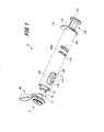
- FIG. 1 is a perspective view showing the drug injection device of this example
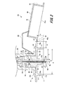
- FIG. 2 is a cross-sectional view showing the injection needle assembly of this example.
- the drug injection device 1 is used when the needle tip is punctured on the surface of the skin and the drug is injected into the upper layer of the skin.
- the skin is composed of three parts: epidermis, dermis, and subcutaneous tissue.
- the epidermis is a layer of about 50 to 200 ⁇ m from the skin surface, and the dermis is a layer of about 1.5 to 3.5 mm continuing from the epidermis.
- Influenza vaccines are generally administered subcutaneously or intramuscularly, and are therefore administered in the lower layer of the skin or deeper.
- the drug injection device 1 of this example is a drug injection device 1 for intradermal injection with such an upper layer portion of the skin as a target site.
- a drug injection device 1 includes an injection needle assembly 2, a syringe 103 that is detachably attached to the injection needle assembly 2, a pusher member 104, and a syringe holder that holds the syringe 103. 105.
- the syringe 103 is a prefilled syringe that is pre-filled with a medicine.
- the syringe 103 includes a syringe main body 111, a discharge portion formed at one end of the syringe main body 111 in the axial direction, a lock mechanism 112 provided in the discharge portion, and a gasket 113.
- the syringe body 111 is formed in a hollow, substantially cylindrical shape.
- a gasket 113 is slidably disposed in the cylindrical hole of the syringe body 111.
- the gasket 113 is formed in a substantially cylindrical shape, and is in liquid-tight contact with the inner peripheral surface of the cylindrical hole of the syringe body 111.
- the gasket 113 has divided the internal space of the syringe main body 111 into two.
- a space closer to the discharge part than the gasket 113 in the syringe body 111 is a liquid chamber 114 filled with a medicine.
- a plunger main body 116 of a pusher member 104 described later is inserted into the space on the other end side of the gasket 113 in the syringe main body 111.
- the material of the gasket 113 is not particularly limited, but is preferably made of an elastic material in order to improve liquid tightness with the syringe body 111.
- the elastic material include various rubber materials such as natural rubber, isobutylene rubber, and silicone rubber, various thermoplastic elastomers such as olefin and styrene, and mixtures thereof.
- the outer diameter and inner diameter of the syringe body 111 are appropriately set according to the use of the drug injection device 1 and the volume of the drug stored in the liquid chamber 114.
- the inner diameter of the syringe body 111 is set to 4.4 to 5.0 mm
- the outer diameter of the syringe body 111 is set to 6. It is preferable to set to 5 to 8.4 mm.
- the volume is 1 mL, it is preferable to set the inner diameter of the syringe body 111 to 6.1 to 9.0 mm and the outer diameter of the syringe body 111 to 7.9 to 12.5 mm.
- drugs include various vaccines that prevent various infectious diseases such as influenza, but are not limited to vaccines.
- drugs other than vaccines include glucose injection solutions such as glucose, electrolyte correction injection solutions such as sodium chloride and potassium lactate, vitamin agents, antibiotic injection solutions, contrast agents, steroid agents, and protease inhibitors Agents, fat emulsions, anticancer agents, anesthetics, heparin calcium, antibody drugs and the like.
- the flange part 115 is formed in the other end part of the syringe body 111 in the axial direction.
- the flange portion 115 is locked to a locking portion 105a provided on a syringe holder 105 described later.
- the discharge part which does not appear in the figure is continuously formed in the one end part of the syringe body 111 in the axial direction.
- the discharge part is formed in a substantially cylindrical shape coaxial with the syringe body 111. Further, the cylindrical hole of the discharge part communicates with the cylindrical hole of the syringe body 111.
- the discharge part is formed in a tapered shape whose diameter continuously decreases toward one end in the axial direction.
- a lock mechanism 112 is provided in the discharge part.
- the lock mechanism 112 is a luer lock portion that shows an example of a fixing mechanism.
- the lock mechanism 112 is formed in a cylindrical shape that surrounds the discharge portion coaxially.
- the lock mechanism 112 has a circular inner periphery and a hexagonal outer periphery.
- An internal thread portion is formed on the inner peripheral surface of the lock mechanism 112.
- the female screw portion is formed so as to be screwable with a male screw portion 35 provided in the injection needle assembly 2.
- Examples of the material of the syringe body 111 include polyvinyl chloride, polyethylene, polypropylene, cyclic polyolefin, polystyrene, poly- (4-methylpentene-1), polycarbonate, acrylic resin, acrylonitrile-butadiene-styrene copolymer, polyethylene.
- Various resins such as polyester such as terephthalate, butadiene-styrene copolymer, polyamide (for example, nylon 6, nylon 6,6, nylon 6,10, nylon 12) can be used.
- the material of the syringe main body 111 is substantially transparent in order to ensure internal visibility.
- the pusher member 104 includes a plunger main body 116 and an operation unit 117 that operates the plunger main body 116.
- the plunger main body 116 is formed in a rod shape.
- the plunger main body 116 is inserted into the cylindrical hole of the syringe main body 111 through an opening formed at the other end in the axial direction of the syringe main body 111.
- One end portion of the plunger main body 116 in the axial direction is in contact with the gasket 113.
- the operation portion 117 is formed at the other end portion of the plunger main body 116 in the axial direction.
- the operation unit 117 is formed in a substantially disk shape.
- the operation unit 117 is pressed by the user. Thereby, the one end part of the axial direction of the plunger main body 116 contact
- the syringe holder 105 is formed in a substantially cylindrical shape.
- the syringe holder 105 covers the outer peripheral surface of the syringe body 111 and the outer peripheral surface of the lock mechanism 112 in the syringe 103.
- the syringe holder 105 is configured to be gripped by the user when the injection needle assembly 2 is attached to the syringe 103.
- a viewing window 118 is formed at one end of the syringe holder 105 in the axial direction.
- the viewing window 118 is provided at a position where the liquid chamber 114 of the syringe 103 can be viewed from the outside of the syringe holder 105 when the syringe 103 is mounted on the syringe holder 105. Thereby, even if the syringe holder 105 is attached to the syringe 103, the internal visibility can be secured.
- a holder collar 119 is formed at the other axial end of the syringe holder 105.
- the holder collar 119 protrudes substantially vertically from a part of the outer peripheral surface of the syringe holder 105.
- a locking portion 105 a is provided in the middle portion of the syringe holder 105 in the axial direction.
- the locking portion 105 a is an opening that penetrates the outer wall of the syringe holder 105.
- the flange portion 115 of the syringe 103 is locked to the locking portion 105a.
- the diameter of the drug injection device 1 can be increased and the drug injection device 1 can be easily held. Thereby, the operativity at the time of operating the pusher member 104 improves.
- the injection needle assembly 2 includes a hollow needle tube 5 having a needle hole, a needle hub 6 to which the needle tube 5 is fixed, and a lid member 40 that covers the needle tube 5 after puncturing. have.
- the needle tube 5 is a size of 26 to 33 gauge (outer diameter 0.2 to 0.45 mm) according to the ISO medical needle tube standard (ISO9626: 1991 / Amd.1: 2001 (E)). And preferably 30 to 33 gauge. A needle thinner than 33 gauge may be used.
- a needle tip 5A having a blade surface 5a is provided at one end of the needle tube 5.
- the axial length of the needle tube 5 on the blade surface 5a (hereinafter referred to as “bevel length B”) may be 1.4 mm (adult) or less, which is the thinnest thickness of the upper skin layer described later.
- the bevel length may be about 0.5 mm or more when a short bevel is formed on a 33 gauge needle tube. That is, the bevel length B is preferably set in the range of 0.5 to 1.4 mm.
- the bevel length B is more preferable if the thinnest thickness of the upper skin portion is 0.9 mm (child) or less, that is, the bevel length B is in the range of 0.5 to 0.9 mm.
- the short bevel refers to a blade surface that is generally used for injection needles and forms an angle of 18 to 25 ° with respect to the longitudinal direction of the needle.
- the material of the needle tube 5 examples include stainless steel, but are not limited thereto, and aluminum, aluminum alloy, titanium, titanium alloy, and other metals can be used.
- the needle tube 5 can be not only a straight needle but also a tapered needle at least partially tapered.
- the proximal end portion has a larger diameter than the needle distal end portion, and the intermediate portion may have a tapered structure.
- the cross-sectional shape of the needle tube 5 may be not only a circle but also a polygon such as a triangle.
- the needle hub 6 includes a first member 11 that holds the needle tube 5, a second member 12 into which the discharge portion of the syringe 103 is inserted, and an elastic member 61.
- the first member 11 and the second member 12 are formed as separate members, but may be formed integrally. Examples of the material of the first member 11 and the second member 12 include synthetic resins such as polycarbonate, polypropylene, and polyethylene.
- the first member 11 includes a base portion 15, an adjustment portion 16, a stabilization portion 17, and a guide portion 18.
- the base portion 15 is formed in a substantially columnar shape, and has end faces 15a and 15b perpendicular to the axial direction.
- the adjustment portion 16 is provided at the center of the end surface 15 a of the base portion 15, and includes a columnar convex portion that protrudes in the axial direction of the base portion 15.
- the axis of the adjustment portion 16 is coincident with the axis of the base portion 15.
- a through-hole 21 through which the needle tube 5 passes is provided in the axial center of the base portion 15 and the adjustment portion 16.
- the base portion 15 is provided with an injection hole 22 (see FIGS. 2 and 4) for injecting the adhesive 20 (see FIG. 3) into the through hole 21.
- the injection hole 22 is opened on the outer peripheral surface of the base portion 15 and communicates with the through hole 21. That is, the needle tube 5 is fixed to the base portion 15 by the adhesive 20 injected from the injection hole 22 into the through hole 21.
- the proximal end side of the needle tube 5 protrudes from the end surface 15 b of the base portion 15.
- the base portion 15 is inserted into the second member 12 from the end surface 15 b side, and the proximal end side of the needle tube 5 is inserted through the insertion hole of the elastic member 61. Then, the end surface 15 b of the base portion 15 is brought into contact with the elastic member 61.
- a connecting piece 24 is provided on the outer peripheral surface of the base portion 15.
- the connection piece 24 is formed as a ring-shaped flange protruding in the radial direction of the base portion 15, and has flat surfaces 24 a and 24 b that face the axial direction of the base portion 15.
- the second member 12 is connected to the flat surface 24 b of the connection piece 24.
- the distal end portion of the connection piece 24 is a guide portion 18. The guide portion 18 will be described in detail later.
- the end surface of the adjusting portion 16 is a needle projecting surface 16a from which the needle tip 5A side of the needle tube 5 projects.
- the needle projecting surface 16 a is formed as a plane orthogonal to the axial direction of the needle tube 5.
- This needle protrusion surface 16a defines the depth at which the needle tube 5 is punctured by contacting the surface of the skin when the needle tube 5 is punctured into the upper layer portion of the skin. That is, the depth at which the needle tube 5 is punctured into the upper skin layer is determined by the length of the needle tube 5 protruding from the needle protruding surface 16a (hereinafter referred to as “projection length L”).
- the thickness of the upper skin portion corresponds to the depth from the skin surface to the dermis layer, and is generally in the range of 0.5 to 3.0 mm. Therefore, the protruding length L of the needle tube 5 can be set in the range of 0.5 to 3.0 mm.
- the vaccine is generally administered to the upper arm, but in the case of administration to the upper skin part, the shoulder peripheral part where the skin is thick, particularly the deltoid part is preferable. Therefore, the thickness of the upper layer of the deltoid muscle was measured for 19 children and 31 adults. This measurement was performed by imaging the upper layer of the skin with high ultrasonic reflectivity using an ultrasonic measurement device (NP60R-UBM, high-resolution echo for small animals, Nepagene). In addition, since the measured value was logarithmic normal distribution, the range of MEAN ⁇ 2SD was obtained by geometric mean.
- the thickness of the upper skin layer of the deltoid muscle of the child was 0.9 to 1.6 mm.
- the thickness of the upper skin layer of the deltoid muscle of adults was 1.4 to 2.6 mm at the distal part, 1.4 to 2.5 mm at the central part, and 1.5 to 2.5 mm at the proximal part. It was. From the above, it was confirmed that the thickness of the upper skin layer in the deltoid muscle was 0.9 mm or more in the case of children and 1.4 mm or more in the case of adults. Therefore, in the injection in the upper layer part of the deltoid muscle, the protruding length L of the needle tube 5 is preferably set in the range of 0.9 to 1.4 mm.
- the blade surface 5a of the needle tip 5A can be reliably positioned on the upper skin layer.
- the needle hole (medicine discharging portion) that opens in the blade surface 5a can be located in the upper skin layer portion at any position within the blade surface 5a. Even if the medicine discharge part is located in the upper skin part, if the needle tip 5A is stabbed deeper than the upper skin part, the medicine flows subcutaneously between the side surface of the end of the needle tip 5A and the cut skin. Therefore, it is important that the blade surface 5a is surely in the upper skin portion.
- the needle projecting surface 16a is formed so that the distance S from the peripheral edge to the outer peripheral surface of the needle tube 5 is 1.4 mm or less, preferably in the range of 0.3 to 1.4 mm.
- the distance S from the peripheral edge of the needle protruding surface 16a to the peripheral surface of the needle tube 5 is set in consideration of the pressure applied to the blisters formed by administering the drug to the upper skin layer. That is, the needle projecting surface 16a is set to a size that is sufficiently smaller than the blisters formed on the upper layer portion of the skin and does not hinder the formation of blisters. As a result, even if the needle protruding surface 16a presses the skin around the needle tube 5, it is possible to prevent the administered medicine from leaking.
- the stabilizing portion 17 is formed in a cylindrical shape protruding from the flat surface 24 a of the connecting piece 24 provided on the base portion 15.
- the needle tube 5 and the adjustment unit 16 are disposed in the cylindrical hole of the stabilization unit 17. That is, the stabilizing portion 17 is formed in a cylindrical shape that covers the periphery of the adjusting portion 16 through which the needle tube 5 passes, and is provided away from the needle tip 5A of the needle tube 5 in the radial direction.
- the end surface 17a of the stabilizing portion 17 is located closer to the proximal end side of the needle tube 5 than the needle protruding surface 16a of the adjusting portion 16.
- the needle projecting surface 16a first contacts the surface of the skin, and then contacts the end surface 17a of the stabilizing portion 17.
- the drug injection device 1 is stabilized by the end surface 17a of the stabilizing portion 17 coming into contact with the skin, and the needle tube 5 can be maintained in a posture substantially perpendicular to the skin.
- the needle tube 5 is skinned. It is possible to keep the posture substantially perpendicular to the angle.
- the axial distance between the end surface 17a of the stable portion 17 and the needle protruding surface 16a is preferably set to 1.3 mm or less.
- the inner diameter d of the stable portion 17 is set to a value equal to or larger than the diameter of the blister formed on the skin.
- the distance T from the inner wall surface of the stabilizing portion 17 to the peripheral edge of the needle protruding surface 16a is set to be in the range of 4 mm to 15 mm. Thereby, it can prevent that blister formation is inhibited by pressure being applied to a blister from the inner wall surface of stable part 17.
- the distance T from the inner wall surface of the stabilizing portion 17 to the periphery of the needle protruding surface 16a is not particularly limited as long as it is 4 mm or more. However, when the distance T is increased, the outer diameter of the stable portion 17 increases, so that it becomes difficult to bring the entire end surface 17a of the stable portion 17 into contact with the skin when the needle tube 5 is punctured into a thin arm like a child. . For this reason, the distance T is preferably set to 15 mm as a maximum in consideration of the thinness of the child's arm.
- the adjusting unit 16 does not enter the skin. Therefore, considering the distance T (4 mm or more) from the inner wall surface of the stable portion 17 to the periphery of the needle protruding surface 16a and the diameter (about 0.3 mm) of the needle protruding surface 16a, the inner diameter d of the stable portion 17 is 9 mm or more. Can be set.
- the shape of the stable part 17 is not limited to a cylindrical shape, and may be formed in a rectangular tube shape such as a quadrangular column or a hexagonal column having a cylindrical hole at the center.
- the guide portion 18 is a portion on the tip side of the connecting piece 24 relative to the stabilizing portion 17.
- the guide portion 18 has a contact surface 18a that comes into contact with the skin.
- the contact surface 18 a is a part of the flat surface 24 a of the connection piece 24, and is a flat surface that is substantially parallel to the end surface 17 a of the stabilizing portion 17.
- the distance Y from the contact surface 18a of the guide portion 18 to the end surface 17a of the stable portion 17 punctures the needle tube 5 and the stable portion 17 by pressing the skin with an appropriate pressing force. Its length is set so that it can.
- the guide portion 18 guides the pressing force applied to the skin by the needle tube 5 and the stabilizing portion 17, and the needle tip 5A (blade surface 5a) of the needle tube 5 can be reliably positioned on the upper layer portion of the skin. Can give you a sense of security.
- An appropriate pressing force of the needle tube 5 and the stabilizing portion 17 is, for example, 3 to 20N.
- the guide portion height Y is the length from the distal end surface of the guide portion 18 to the outer peripheral surface of the stable portion 17 (hereinafter referred to as “guide portion length”). It is determined appropriately based on X. For example, when the inner diameter d of the stabilizing portion 17 is 12 mm and the guide portion length X is 3.0 mm, the guide portion height Y is set in the range of 2.3 to 6.6 mm.
- the second member 12 is formed in a cylindrical shape.
- One end portion of the second member 12 in the axial direction is an insertion portion 31 into which the base portion 15 of the first member 11 is inserted, and the other end portion is an insertion portion into which the discharge portion of the syringe 103 is inserted. Yes.
- the cylindrical hole 31 a of the insertion portion 31 is set to a size corresponding to the base portion 15 of the first member 11.
- a fixing piece 34 is provided on the outer peripheral surface of one end portion of the second member 12 in the insertion portion 31 in the axial direction.
- the fixing piece 34 is formed as a ring-shaped flange that protrudes outward in the radial direction continuously to the distal end of the insertion portion 31.
- a flat surface 24b of the connection piece 24 provided on the first member 11 is brought into contact with and fixed to the fixed piece 34. Examples of the fixing method of the fixing piece 34 and the connection piece 24 include an adhesive, ultrasonic welding, laser welding, and a fixing screw.
- the outer diameter of the insertion part is set smaller than the outer diameter of the insertion part 31. Further, the tube hole of the fitting portion is set to a size corresponding to the discharge portion of the syringe 103, and the diameter continuously decreases toward the insertion portion 31 side. Moreover, the external thread part 35 for screwing together with the locking mechanism 112 of the syringe 103 is provided in the outer peripheral surface of the insertion part (refer FIG. 1). An elastic member 61 is disposed between the cylindrical hole 31a of the insertion portion 31 and the cylindrical hole of the insertion portion.
- the elastic member 61 is a member that can be elastically deformed.
- Examples of the material of the elastic member 61 include various rubber materials such as natural rubber, silicone rubber, and isobutylene rubber, various thermoplastic elastomers such as polyurethane and styrene, or elastic materials such as a mixture thereof. .
- the elastic member 61 is disposed in the second member 12 and is interposed between the first member 11 and the syringe 103. Then, a gap generated between the outer peripheral surface on the proximal end side of the needle tube 5 protruding from the first member 11 and the second member 12 is filled.
- the elastic member 61 is elastically deformed to be in liquid-tight contact with the outer peripheral surface of the needle tube 5. Thereby, it is possible to prevent the medicine filled in the syringe 103 from penetrating between the needle tube 5 and the elastic member 61 and leaking to the first member 11 side.
- the lid member 40 is provided on the outer edge of the needle hub 6 on the outer side in the radial direction of the guide portion 18.
- the lid member 40 has a main body portion 41, a connecting portion 42, and an urging portion 43.
- the main body 41 is formed in a substantially cylindrical shape.
- the main body 41 includes a circular top plate 44 and side wall portions 45 that are bent substantially perpendicularly from the edge of the top plate 44 and are continuously formed along the circumferential direction of the top plate 44. .
- the diameter of the top plate 44 is set larger than the outer diameter of the stable portion 17. Further, the length of the side wall portion 45, that is, the length of the main body portion 41 in the axial direction is set to be longer than the guide portion height Y and the length of the needle tube 5 protruding from the adjusting portion 16. That is, the main body 41 is formed in a size capable of covering the needle tip 5A side of the needle tube 5, the adjustment unit 16 and the stabilization unit 17 as a whole (see FIG. 5). Further, the main body 41 is connected to the needle hub 6 via the connecting portion 42.
- the connecting portion 42 is provided on the outer edge portion of the guide portion 18. A location where the connecting portion 42 is connected to the guide portion 18 is a thin portion 42a having a smaller thickness than other locations. And the connection part 42 is supporting the main-body part 41 so that rotation is possible about the thin part 42a. Further, an urging portion 43 is disposed between the connecting portion 42 and the needle hub 6.
- the urging portion 43 is formed by an elastic leaf spring.
- the urging portion 43 includes a plurality of linear portions in FIG. 2 showing a cross section and a bent portion provided therebetween. In this example, three linear parts are provided and two bent parts are provided. And the urging
- One end of the urging portion 43 in the longitudinal direction is fixed to the top plate 44 of the main body portion 41.
- the other end of the urging portion 43 in the longitudinal direction is fixed to the insertion portion 31 of the second member 12 in the needle hub 6.
- biasing part 43 is not limited to this.
- one end portion in the longitudinal direction of the urging portion 43 may be fixed to the side wall portion 45 of the main body portion 41, and the other end portion in the longitudinal direction of the urging portion 43 may be fixed to the fixing piece 34 of the second member 12.
- one end portion in the longitudinal direction of the urging portion 43 may be fixed to the main body portion 41, and the other end portion in the longitudinal direction of the urging portion 43 may be fixed to any part of the needle hub 6.
- the urging portion 43 does not have a linear portion and a bent portion, but may be a generally curved portion (C shape, U shape, etc.) or a combination thereof. good.
- the connecting portion 42 and the urging portion 43 in the main body portion 41 is at the tip end side in the axial direction of the needle hub 6 relative to the contact surface 18 a of the needle hub 6.
- the main body 41 is held in a state of protruding toward the needle tip 5 ⁇ / b> A side of the needle tube 5.
- the portion farthest from the connecting portion 42 protrudes toward the distal end side of the needle hub 6 in the axial direction from the contact surface 18a. That is, the end surface 41a on the opening side of the main body 41, that is, the end surface on the side opposite to the top plate 44 in the side wall portion 45 is inclined with respect to the contact surface 18a.
- the example which formed the main-body part 41 in the cylindrical shape was demonstrated in this example, it is not limited to this, For example, it forms in square tube shapes, such as a square column and a hexagonal column, which have a cylindrical hole in the center. May be. Further, since it is sufficient that the needle tip 5A of the needle tube 5 can be covered, the main body portion may be formed in a flat plate shape, and a part of the needle tip 5A of the needle tube 5 may be punctured or bent.
- FIG. 3 is a cross-sectional view showing the main part of the drug injection device 1 during puncturing
- FIGS. 4 and 5 are cross-sectional views showing the main part of the drug injection device 1 after puncturing.
- the syringe 103 is attached to the injection needle assembly 2. Specifically, the discharge portion of the syringe 103 is inserted into the fitting portion of the second member 12, and the lock mechanism 112 is screwed into the male screw portion 35. Thereby, the mounting of the injection needle assembly 2 to the syringe 103 is completed. As shown in FIG. 2, the main body 41 of the lid member 40 is separated from the needle tip 5A of the needle tube 5, and the needle tip 5A of the needle tube 5 is exposed. Let the position of the main-body part 41 at this time be a 1st position.
- the end surface 17a of the stabilizing part 17 is made to face the skin.
- the needle tip 5A of the needle tube 5 is opposed to the skin to be punctured.
- the drug injection device 1 is moved substantially perpendicularly to the skin, the needle tip 5A is punctured into the skin, and the end surface 17a of the stabilizing portion 17 is pressed against the skin.
- the needle protruding surface 16a can come into contact with the skin to deform the skin flatly, and the needle tip 5A side of the needle tube 5 can be punctured into the skin by the protruding length L.
- the end surface 17a of the stabilizing portion 17 is pressed until the contact surface 18a of the guide portion 18 contacts the skin.
- the length of the guide portion height Y is set so that the needle tube 5 and the stabilizing portion 17 can puncture the skin with an appropriate pressing force. Therefore, the force that presses the skin by the stabilizing portion 17 becomes a predetermined value.
- the user can recognize an appropriate pressing force of the stabilizing portion 17, and the needle tip 5A and the blade surface 5a of the needle tube 5 can be surely positioned on the upper skin portion.
- the guide part 18 becomes a mark for recognizing an appropriate pressing force of the stable part 17, so that the user can use the medicine injection device 1 with peace of mind.
- the stabilizing portion 17 contacts the skin, the posture of the medicine injection device 1 is stabilized, and the needle tube 5 can be punctured straight to the skin. Moreover, the blurring which arises in the needle tube 5 after puncture can be prevented, and the administration of the medicine can be performed stably.
- the main body 41 of the lid member 40 protrudes toward the distal end side in the axial direction of the needle hub 6 from the contact surface 18a. Therefore, the end surface 41a of the main body 41 comes into contact with the skin before the contact surface 18a comes into contact with the skin.
- the main body portion 41 moves away from the needle tip 5A of the needle tube 5 with the thin portion 42a of the connecting portion 42 as a fulcrum. Rotate in the direction. As a result, the end surface 41a of the main body 41 is parallel to the contact surface 18a.
- the urging portion 43 As the main body 41 rotates in a direction away from the needle tip 5A of the needle tube 5, the urging portion 43 is elastically deformed, and the linear portion of the urging portion 43 is distorted or the bending angle of the bending portion is increased. Or change. Therefore, the urging force is accumulated in the urging unit 43.
- the pusher member 104 (see FIG. 1) is pushed to move the gasket 113 to the discharge portion side.
- the medicine filled in the liquid chamber 114 of the syringe 103 is pushed out from the discharge part, and is injected into the upper skin part from the needle tip 5A through the needle hole of the needle tube 5.
- the remaining amount of the medicine can be reduced.
- the drug injection device 1 is separated from the skin, and the end surface 17 a of the stabilizing portion 17, the needle protruding surface 16 a and the end surface 41 a of the main body portion 41 are separated from the skin.
- the pressing force from the skin is released from the urging portion 43 via the main body portion 41.
- the main body 41 is pressed by the restoring force (biasing force) of the urging portion 43 and rotates in a direction approaching the needle tip 5A of the needle tube 5 with the thin portion 42a of the connecting portion 42 as a fulcrum.
- the needle tip 5A of the needle tube 5 can be kept in a safe state after use, and the needle tip 5A of the used needle tube 5 can be prevented from being punctured against the intention of the user. Furthermore, since the needle tip 5A of the used needle tube 5 is covered with the main body 41, it is possible to prevent the blood adhering to the needle tip 5A from being scattered and to prevent infection by blood.
- the main body portion 41 is automatically rotated by the urging force accumulated in the urging portion 43.
- the main body 41 is automatically rotated by the urging force accumulated in the urging portion 43.
- the urging portion 43 of the rotated lid member 40 urges the main body portion 41 in a direction in which the end surface 41a of the main body portion 41 is pressed against the contact surface 18a. Thereby, it can prevent that the main-body part 41 rotates in the direction away
- FIG. 6 is an enlarged cross-sectional view of a main part of the medicine injection device according to the second embodiment.
- the difference between the drug injection device according to the second embodiment and the drug injection device 1 according to the first embodiment is the configuration of the lid member in the injection needle assembly. Therefore, here, the lid member will be mainly described, and the portions common to the injection needle assembly 2 according to the first embodiment are denoted by the same reference numerals, and redundant description is omitted.
- the injection needle assembly 2 ⁇ / b> A includes a hollow needle tube 5, a needle hub 6 that holds the needle tube 5, and a lid member 70.
- the lid member 70 has a substantially cylindrical main body 71, a connecting portion 72, and an urging portion 73.
- the main body 71 has a circular top plate 74, a side wall 75, and a contact protrusion 76.
- the contact protrusion 76 is disposed at a position farthest from the connecting portion 72 on the end surface 71 a of the main body 71. Further, the contact protrusion 76 protrudes in a direction away from the top plate 74 from the end surface 71a.
- the main body 71 is rotatably supported by the connecting portion 72.
- the connecting portion 72 and the biasing portion 73 hold the main body 71 so that the end surface 71a of the main body 71 is substantially parallel to the contact surface 18a. Therefore, the contact protrusion 76 protrudes further toward the distal end side in the axial direction of the needle hub 6 than the contact surface 18a.
- the contact protrusion 76 of the main body 71 contacts the skin before the contact surface 18a contacts the skin.
- the main body 71 rotates in a direction away from the needle tip 5A of the needle tube 5 with the thin portion 72a of the connecting portion 72 as a fulcrum. To do.
- the urging portion 73 is elastically deformed, and the urging force is accumulated in the urging portion 73.
- the contact surface 18a of the guide portion 18 is provided with a fitting recess 18b into which the contact protrusion 76 of the rotated lid member 70 is fitted.
- FIG. 7 is an enlarged cross-sectional view showing a main part of the medicine injection device according to the third embodiment.
- the difference between the drug injection device according to the third embodiment and the drug injection device 1 according to the first embodiment is the configuration of the lid member in the injection needle assembly. Therefore, here, the lid member will be mainly described, and the portions common to the injection needle assembly 2 according to the first embodiment are denoted by the same reference numerals, and redundant description is omitted.
- the injection needle assembly 2B includes a hollow needle tube 5, a needle hub 6 that holds the needle tube 5, and a lid member 80.
- the lid member 80 includes a first main body portion 81A, a first connecting portion 82A, a first biasing portion 83A, a second main body portion 81B, a second connecting portion 82B, and a second attaching portion. And a force portion 83B.
- the first main body 81 ⁇ / b> A, the first connecting portion 82 ⁇ / b> A, and the first biasing portion 83 ⁇ / b> A are provided on the outer edge portion of the guide portion 18.
- the second main body portion 81B, the second connecting portion 82B, and the second urging portion 83B sandwich the guide portion 18 therebetween, and the first main body portion 81A, the first connecting portion 82A, and the first attaching portion 83B. It is provided on the outer edge portion of the guide portion 18 on the opposite side to the biasing portion 83A.
- the configurations of the second main body portion 81B, the second connecting portion 82B, and the second biasing portion 83B are the same as those of the first main body portion 81A, the first connecting portion 82A, and the first biasing portion 83A. Therefore, here, the first main body 81A, the first connecting portion 82A, and the first urging portion 83A will be described.
- the first main body 81A is formed in a substantially semi-cylindrical shape.
- the first main body 81 ⁇ / b> A includes a substantially semicircular top plate 84 and a side wall 85.
- the first main body portion 81A is rotatably supported by the first connecting portion 82A.
- the first connecting portion 82A and the first urging portion 83A are such that at least a part of the first main body portion 81A protrudes further toward the distal end side in the axial direction of the needle hub 6 than the contact surface 18a. Hold to do.
- the lid member 80 rotates in a direction in which the first main body 81A and the second main body 81B approach the needle tip 5A of the needle tube 5.
- the needle tip 5A of the needle tube 5 is covered with the first main body 81A and the second main body 81B.
- the main body is divided into the first main body 81A and the second main body 81B. Even when the needle tube 5 is punctured into a thin arm like a child, either the first main body 81A or the second main body 81B can be reliably pressed against the skin. As a result, after puncturing, at least one of the first main body portion 81A and the second main body portion 81B can be rotated, and the needle tip 5A of the needle tube 5 can be reliably covered.
- the present invention is not limited to this, and the male screw portion is provided in the discharge portion, and the second member 12 of the injection needle assembly is provided.
- An internal thread portion may be provided in the cylindrical hole and screwed.
- SYMBOLS 1 Drug injection device 2, 2A, 2B ... Injection needle assembly, 5 ... Needle tube, 5A ... Needle tip, 5a ... Blade surface, 6 ... Needle hub, 11 ... First member, 12 ... Second member, 13 ... Gasket, 15 ... Base part, 16 ... Adjusting part, 16a ... Needle protruding surface, 17 ... Stabilizing part, 17a ... End face, 18 ... Guide part, 18a ... Contact surface, 18b ... Fitting recess, 40, 70, 80 ... Lid 41, 71 ... main body, 41a, 71a ... end face, 42, 72 ... connecting part, 42a, 72a ...
Landscapes
- Health & Medical Sciences (AREA)
- Engineering & Computer Science (AREA)
- Heart & Thoracic Surgery (AREA)
- Vascular Medicine (AREA)
- Anesthesiology (AREA)
- Biomedical Technology (AREA)
- Hematology (AREA)
- Life Sciences & Earth Sciences (AREA)
- Animal Behavior & Ethology (AREA)
- General Health & Medical Sciences (AREA)
- Public Health (AREA)
- Veterinary Medicine (AREA)
- Environmental & Geological Engineering (AREA)
- Infusion, Injection, And Reservoir Apparatuses (AREA)
Abstract
This injection needle assembly is provided with a needle tube, a needle hub, a main body part, a coupling part, and an impelling part. The main body part is capable of moving between a first position which is away from the tip of the needle tube, and in which the tip of the needle tube is exposed, and a second position in which the tip of the needle tube is covered. Furthermore, in the first position, at least a portion of the main body part protrudes further towards the side of the tip of the needle tube than a contact surface.
Description
本発明は、薬剤を生体に注入する際に用いられる注射針組立体および薬剤注射装置に関する。
The present invention relates to an injection needle assembly and a drug injection device used when a drug is injected into a living body.
薬剤注射装置は、針管を有する注射針組立体と、薬剤を収容するシリンジとを、備えて構成されている。注射針組立体に設けられた針管は、生体に穿刺可能な針先を有している。この針管の針先は、常に露出しているため、薬剤の投与後や薬剤注射装置の廃棄時に針管の針先が誤って使用者に穿刺されるおそれがある。
The drug injection device includes an injection needle assembly having a needle tube and a syringe for storing the drug. A needle tube provided in the injection needle assembly has a needle tip that can puncture a living body. Since the needle tip of this needle tube is always exposed, the needle tip of the needle tube may be accidentally punctured by the user after administration of the drug or when the drug injection device is discarded.
このような不具合を解消するため、例えば、特許文献1には、回動可能なプロテクタ本体と、回動支持部とを備えた技術が記載されている。そして、特許文献1に記載された技術では、針管を生体に穿刺した後に、プロテクタ本体を回動させて、針管の針先をプロテクタ本体で覆っている。これにより、使用後の針管の針先が誤って使用者に穿刺されることを防いでいる。
In order to solve such a problem, for example, Patent Document 1 describes a technique including a rotatable protector body and a rotation support portion. In the technique described in Patent Literature 1, after the needle tube is punctured into the living body, the protector main body is rotated to cover the needle tip of the needle tube with the protector main body. This prevents the user from accidentally puncturing the needle tip of the used needle tube.
しかしながら、特許文献1に記載された技術では、プロテクタ本体の回動操作は、使用者の手によって行われていた。そのため、使用者がプロテクタ本体の回動操作を忘れるおそれがあるだけでなく、プロテクタ本体を回動させる際に、誤って使用者の手指等が針管の針先に穿刺されるおそれがあった。
However, in the technique described in Patent Document 1, the rotation operation of the protector body is performed by the user's hand. Therefore, not only the user may forget to rotate the protector body, but also the user's finger may be accidentally punctured into the needle tip of the needle tube when rotating the protector body.
本発明の目的は、上記の問題点を考慮し、使用後の針管の針先を確実に覆うことができ、安全性の向上を図ることがきる注射針組立体及び薬剤注射装置を提供することにある。
In view of the above problems, an object of the present invention is to provide an injection needle assembly and a drug injection device that can reliably cover the needle tip of a used needle tube and can improve safety. It is in.
上記課題を解決し、本発明の目的を達成するため、本発明の注射針組立体は、針管と、針ハブと、本体部と、連結部と、付勢部と、を備えている。針管は、生体に穿刺可能な針先を有する。針ハブは、針管を保持し、針管の針先を生体に穿刺する際に生体に接触する接触面を有する。本体部は、針管の針先から離間して針管の針先を露出させる第1の位置と、針管の針先を覆う第2の位置に移動可能となっている。連結部は、本体部を針ハブに回動可能に連結する。付勢部は、本体部に設けられ、弾性変形した際に本体部を第1の位置から第2の位置に向けて付勢する。そして、第1の位置において、本体部における少なくとも一部が接触面よりも針管の針先側に突出する。
In order to solve the above-described problems and achieve the object of the present invention, the injection needle assembly of the present invention includes a needle tube, a needle hub, a main body portion, a connecting portion, and a biasing portion. The needle tube has a needle tip that can puncture a living body. The needle hub has a contact surface that holds the needle tube and contacts the living body when the needle tip of the needle tube is punctured into the living body. The main body is movable to a first position where the needle tip of the needle tube is exposed while being separated from the needle tip of the needle tube, and a second position which covers the needle tip of the needle tube. The connecting portion rotatably connects the main body portion to the needle hub. The urging portion is provided in the main body portion and urges the main body portion from the first position toward the second position when elastically deforming. And in a 1st position, at least one part in a main-body part protrudes in the needle tip side of a needle tube rather than a contact surface.
また、本発明の薬剤注射装置は、注射針組立体と、注射針組立体に着脱可能に装着されるシリンジと、を備えている。注射針組立体は、上述した注射針組立体が用いられる。
The drug injection device of the present invention includes an injection needle assembly and a syringe that is detachably attached to the injection needle assembly. The injection needle assembly described above is used as the injection needle assembly.
本発明の注射針組立体及び薬剤注射装置によれば、使用後の針管の針先を確実に本体部によって覆うことができ、使用後の針管の針先が誤って使用者に穿刺されることを防ぐことができる。そのため、安全性の向上を図ることができる。
According to the injection needle assembly and drug injection device of the present invention, the needle tip of the used needle tube can be reliably covered with the main body, and the needle tip of the used needle tube is erroneously punctured by the user. Can be prevented. Therefore, safety can be improved.
以下、本発明の注射針組立体及び薬剤注射装置の実施形態例について、図1~図7を参照して説明する。なお、各図において共通の部材には、同一の符号を付している。また、本発明は、以下の形態に限定されるものではない。
なお、説明は以下の順序で行う。
1.第1の実施の形態例
1-1.注射針組立体及び薬剤注射装置の構成例
1-2.薬剤注射装置の使用方法
2.第2の実施の形態例
3.第3の実施の形態例 Embodiments of an injection needle assembly and a drug injection device according to the present invention will be described below with reference to FIGS. In addition, the same code | symbol is attached | subjected to the common member in each figure. The present invention is not limited to the following form.
The description will be given in the following order.
1. First Embodiment 1-1. Configuration example of injection needle assembly and drug injection device 1-2. 1. Method of using drug injection device Second embodiment example 3. FIG. Third embodiment
<1.第1の実施の形態例>
1-1.注射針組立体及び薬剤注射装置の構成例
まず、図1~図2を参照して本発明の第1の実施の形態例(以下、「本例」という。)にかかる注射針組立体及び薬剤注射装置について説明する。
図1は本例の薬剤注射装置を示す斜視図、図2は本例の注射針組立体を示す断面図である。 <1. First Embodiment>
1-1. Configuration Example of Injection Needle Assembly and Drug Injection Device First, referring to FIGS. 1 and 2, the injection needle assembly and the drug according to the first embodiment of the present invention (hereinafter referred to as “this example”) The injection device will be described.
FIG. 1 is a perspective view showing the drug injection device of this example, and FIG. 2 is a cross-sectional view showing the injection needle assembly of this example.
薬剤注射装置1は、針先を皮膚の表面に穿刺し、皮膚上層部に薬剤を注入する場合に用いる。
The drug injection device 1 is used when the needle tip is punctured on the surface of the skin and the drug is injected into the upper layer of the skin.
ここで、皮膚は、表皮と、真皮と、皮下組織の3部分から構成される。表皮は、皮膚表面から50~200μm程度の層であり、真皮は、表皮から続く1.5~3.5mm程度の層である。インフルエンザワクチンは、一般的に皮下投与もしくは筋肉内投与であるため、皮膚の下層部もしくはそれよりも深い部分に投与されている。
Here, the skin is composed of three parts: epidermis, dermis, and subcutaneous tissue. The epidermis is a layer of about 50 to 200 μm from the skin surface, and the dermis is a layer of about 1.5 to 3.5 mm continuing from the epidermis. Influenza vaccines are generally administered subcutaneously or intramuscularly, and are therefore administered in the lower layer of the skin or deeper.
一方、免疫担当細胞が多く存在する皮膚上層部を標的部位として、インフルエンザワクチンを投与することにより、ワクチンの投与量を減少させることが検討されている。なお、皮膚上層部とは、皮膚のうちの表皮と真皮を指す。本例の薬剤注射装置1は、このような皮膚上層部を標的部位とした皮内注射用の薬剤注射装置1である。
On the other hand, it has been studied to reduce the dose of the vaccine by administering the influenza vaccine with the upper skin layer where many immunocompetent cells are present as the target site. The upper skin layer refers to the epidermis and dermis of the skin. The drug injection device 1 of this example is a drug injection device 1 for intradermal injection with such an upper layer portion of the skin as a target site.
図1に示すように、薬剤注射装置1は、注射針組立体2と、この注射針組立体2に着脱可能に装着されるシリンジ103と、押し子部材104と、シリンジ103を保持するシリンジホルダ105と、を有している。
As shown in FIG. 1, a drug injection device 1 includes an injection needle assembly 2, a syringe 103 that is detachably attached to the injection needle assembly 2, a pusher member 104, and a syringe holder that holds the syringe 103. 105.
[シリンジ]
シリンジ103は、予め薬剤が充填されているプレフィルドシリンジである。このシリンジ103は、シリンジ本体111と、シリンジ本体111の軸方向の一端部に形成された排出部と、排出部に設けられたロック機構112と、ガスケット113とを有している。 [Syringe]
Thesyringe 103 is a prefilled syringe that is pre-filled with a medicine. The syringe 103 includes a syringe main body 111, a discharge portion formed at one end of the syringe main body 111 in the axial direction, a lock mechanism 112 provided in the discharge portion, and a gasket 113.
シリンジ103は、予め薬剤が充填されているプレフィルドシリンジである。このシリンジ103は、シリンジ本体111と、シリンジ本体111の軸方向の一端部に形成された排出部と、排出部に設けられたロック機構112と、ガスケット113とを有している。 [Syringe]
The
シリンジ本体111は、中空の略円筒状に形成されている。また、シリンジ本体111の筒孔内には、ガスケット113が摺動可能に配置されている。ガスケット113は、略円柱状に形成されており、シリンジ本体111の筒孔の内周面に液密に密着している。そして、ガスケット113は、シリンジ本体111の内部空間を2つに仕切っている。シリンジ本体111内におけるガスケット113よりも排出部側の空間は、薬剤が充填される液室114となる。一方、シリンジ本体111内におけるガスケット113よりも他端側の空間には、後述する押し子部材104のプランジャ本体116が挿入される。
The syringe body 111 is formed in a hollow, substantially cylindrical shape. A gasket 113 is slidably disposed in the cylindrical hole of the syringe body 111. The gasket 113 is formed in a substantially cylindrical shape, and is in liquid-tight contact with the inner peripheral surface of the cylindrical hole of the syringe body 111. And the gasket 113 has divided the internal space of the syringe main body 111 into two. A space closer to the discharge part than the gasket 113 in the syringe body 111 is a liquid chamber 114 filled with a medicine. On the other hand, a plunger main body 116 of a pusher member 104 described later is inserted into the space on the other end side of the gasket 113 in the syringe main body 111.
ガスケット113の材質は、特に限定されないが、シリンジ本体111との液密性を良好にするために弾性材料で構成することが好ましい。この弾性材料としては、例えば、天然ゴム、イソブチレンゴム、シリコーンゴムなどの各種ゴム材料や、オレフィン系、スチレン系等の各種熱可塑性エラストマー、あるいはそれらの混合物等を挙げることができる。
The material of the gasket 113 is not particularly limited, but is preferably made of an elastic material in order to improve liquid tightness with the syringe body 111. Examples of the elastic material include various rubber materials such as natural rubber, isobutylene rubber, and silicone rubber, various thermoplastic elastomers such as olefin and styrene, and mixtures thereof.
シリンジ本体111の外径及び内径は、薬剤注射装置1を使用する用途や、液室114に収容する薬剤の容量に応じて適宜設定されるものである。例えば、汎用の高速充填機を用いて収容する薬剤の容量を0.5mLにする場合は、シリンジ本体111の内径を4.4~5.0mmに設定し、シリンジ本体111の外径を6.5~8.4mmに設定することが好ましい。また、容量を1mLにする場合は、シリンジ本体111の内径を6.1~9.0mmに設定し、シリンジ本体111の外径を7.9~12.5mmに設定することが好ましい。
The outer diameter and inner diameter of the syringe body 111 are appropriately set according to the use of the drug injection device 1 and the volume of the drug stored in the liquid chamber 114. For example, when the volume of the medicine to be stored using a general-purpose high-speed filling machine is 0.5 mL, the inner diameter of the syringe body 111 is set to 4.4 to 5.0 mm, and the outer diameter of the syringe body 111 is set to 6. It is preferable to set to 5 to 8.4 mm. When the volume is 1 mL, it is preferable to set the inner diameter of the syringe body 111 to 6.1 to 9.0 mm and the outer diameter of the syringe body 111 to 7.9 to 12.5 mm.
薬剤としては、例えば、インフルエンザ等の各種の感染症を予防する各種のワクチンが挙げられるが、ワクチンに限定されるものではない。なお、ワクチン以外の薬剤としては、例えば、ブドウ糖等の糖質注射液、塩化ナトリウムや乳酸カリウム等の電解質補正用注射液、ビタミン剤、抗生物質注射液、造影剤、ステロイド剤、蛋白質分解酵素阻害剤、脂肪乳剤、抗癌剤、麻酔薬、ヘパリンカルシウム、抗体医薬等が挙げられる。
Examples of drugs include various vaccines that prevent various infectious diseases such as influenza, but are not limited to vaccines. Examples of drugs other than vaccines include glucose injection solutions such as glucose, electrolyte correction injection solutions such as sodium chloride and potassium lactate, vitamin agents, antibiotic injection solutions, contrast agents, steroid agents, and protease inhibitors Agents, fat emulsions, anticancer agents, anesthetics, heparin calcium, antibody drugs and the like.
シリンジ本体111の軸方向の他端部には、フランジ部115が形成されている。フランジ部115は、後述するシリンジホルダ105に設けた係止部105aに係止される。また、シリンジ本体111の軸方向の一端部には、図に表れない排出部が連続して形成されている。
The flange part 115 is formed in the other end part of the syringe body 111 in the axial direction. The flange portion 115 is locked to a locking portion 105a provided on a syringe holder 105 described later. Moreover, the discharge part which does not appear in the figure is continuously formed in the one end part of the syringe body 111 in the axial direction.
排出部は、シリンジ本体111と同軸の略円筒状に形成されている。また、排出部の筒孔は、シリンジ本体111の筒孔に連通している。排出部は、軸方向の一端部に向かうにつれて径が連続的に小さくなるテーパ状に形成されている。シリンジ103に注射針組立体2を取り付けた際に、排出部の先端部は、後述する注射針組立体2の弾性部材61の端面に液密に当接する。
The discharge part is formed in a substantially cylindrical shape coaxial with the syringe body 111. Further, the cylindrical hole of the discharge part communicates with the cylindrical hole of the syringe body 111. The discharge part is formed in a tapered shape whose diameter continuously decreases toward one end in the axial direction. When the injection needle assembly 2 is attached to the syringe 103, the distal end portion of the discharge portion comes into liquid-tight contact with the end surface of the elastic member 61 of the injection needle assembly 2 described later.
排出部には、ロック機構112が設けられている。ロック機構112は、固定機構の一例を示すルアーロック部である。ロック機構112は、排出部を同軸で取り囲む筒状に形成されている。また、ロック機構112は、その内周が円形であり、外周は六角形状に形成されている。このロック機構112の内周面には、雌ねじ部が形成されている。雌ねじ部は、注射針組立体2に設けられた雄ねじ部35と螺合可能に形成されている。
A lock mechanism 112 is provided in the discharge part. The lock mechanism 112 is a luer lock portion that shows an example of a fixing mechanism. The lock mechanism 112 is formed in a cylindrical shape that surrounds the discharge portion coaxially. The lock mechanism 112 has a circular inner periphery and a hexagonal outer periphery. An internal thread portion is formed on the inner peripheral surface of the lock mechanism 112. The female screw portion is formed so as to be screwable with a male screw portion 35 provided in the injection needle assembly 2.
シリンジ本体111の材質としては、例えば、ポリ塩化ビニル、ポリエチレン、ポリプロピレン、環状ポリオレフィン、ポリスチレン、ポリ-(4-メチルペンテン-1)、ポリカーボネート、アクリル樹脂、アクリルニトリル-ブタジエン-スチレン共重合体、ポリエチレンテレフタレート等のポリエステル、ブタジエン-スチレン共重合体、ポリアミド(例えば、ナイロン6、ナイロン6・6、ナイロン6・10、ナイロン12)のような各種樹脂が挙げられる。その中でも、成形が容易であるという点で、ポリプロピレン、環状ポリオレフィン、ポリエステル、ポリ-(4-メチルペンテン-1)のような樹脂を用いることが好ましい。なお、シリンジ本体111の材質は、内部の視認性を確保するために、実質的に透明であることが好ましい。
Examples of the material of the syringe body 111 include polyvinyl chloride, polyethylene, polypropylene, cyclic polyolefin, polystyrene, poly- (4-methylpentene-1), polycarbonate, acrylic resin, acrylonitrile-butadiene-styrene copolymer, polyethylene. Various resins such as polyester such as terephthalate, butadiene-styrene copolymer, polyamide (for example, nylon 6, nylon 6,6, nylon 6,10, nylon 12) can be used. Among them, it is preferable to use a resin such as polypropylene, cyclic polyolefin, polyester, or poly- (4-methylpentene-1) in terms of easy molding. In addition, it is preferable that the material of the syringe main body 111 is substantially transparent in order to ensure internal visibility.
なお、本例では、シリンジ103として予め薬剤が充填されたプレフィルドシリンジを適用した例を説明したが、これに限定されるものではなく、薬剤を予めシリンジ本体内に充填しないシリンジを適用してもよい。
In addition, although the example which applied the prefilled syringe with which the chemical | medical agent was beforehand filled as the syringe 103 was demonstrated in this example, it is not limited to this, Even if it applies the syringe which does not fill a syringe main body beforehand. Good.
[押し子部材]
押し子部材104は、プランジャ本体116と、プランジャ本体116を操作する操作部117とを有している。プランジャ本体116は、棒状に形成されている。プランジャ本体116は、シリンジ本体111の軸方向の他端部に形成された開口部からシリンジ本体111の筒孔内に挿入される。そして、プランジャ本体116の軸方向の一端部は、ガスケット113に当接する。 [Pushing member]
Thepusher member 104 includes a plunger main body 116 and an operation unit 117 that operates the plunger main body 116. The plunger main body 116 is formed in a rod shape. The plunger main body 116 is inserted into the cylindrical hole of the syringe main body 111 through an opening formed at the other end in the axial direction of the syringe main body 111. One end portion of the plunger main body 116 in the axial direction is in contact with the gasket 113.
押し子部材104は、プランジャ本体116と、プランジャ本体116を操作する操作部117とを有している。プランジャ本体116は、棒状に形成されている。プランジャ本体116は、シリンジ本体111の軸方向の他端部に形成された開口部からシリンジ本体111の筒孔内に挿入される。そして、プランジャ本体116の軸方向の一端部は、ガスケット113に当接する。 [Pushing member]
The
操作部117は、プランジャ本体116の軸方向の他端部に形成されている。操作部117は、略円盤状に形成されている。薬剤注射装置1を使用する際に、操作部117は、使用者によって押圧される。これにより、プランジャ本体116の軸方向の一端部がガスケット113に当接し、ガスケット113を排出部に向けて摺動させる。
The operation portion 117 is formed at the other end portion of the plunger main body 116 in the axial direction. The operation unit 117 is formed in a substantially disk shape. When the medicine injection device 1 is used, the operation unit 117 is pressed by the user. Thereby, the one end part of the axial direction of the plunger main body 116 contact | abuts to the gasket 113, and makes the gasket 113 slide toward a discharge part.
また、押し子部材104の材質としては、シリンジ本体111の材質として挙げた各種樹脂を適用することができる。
Further, as the material of the pusher member 104, various resins mentioned as the material of the syringe body 111 can be applied.
[シリンジホルダ]
次に、シリンジホルダ105について説明する。
シリンジホルダ105は、略円筒状に形成されている。シリンジホルダ105は、シリンジ103におけるシリンジ本体111の外周面及びロック機構112の外周面を覆う。そして、シリンジホルダ105は、シリンジ103に注射針組立体2を取り付ける際に、使用者によって把持可能に構成されている。 [Syringe holder]
Next, thesyringe holder 105 will be described.
Thesyringe holder 105 is formed in a substantially cylindrical shape. The syringe holder 105 covers the outer peripheral surface of the syringe body 111 and the outer peripheral surface of the lock mechanism 112 in the syringe 103. The syringe holder 105 is configured to be gripped by the user when the injection needle assembly 2 is attached to the syringe 103.
次に、シリンジホルダ105について説明する。
シリンジホルダ105は、略円筒状に形成されている。シリンジホルダ105は、シリンジ103におけるシリンジ本体111の外周面及びロック機構112の外周面を覆う。そして、シリンジホルダ105は、シリンジ103に注射針組立体2を取り付ける際に、使用者によって把持可能に構成されている。 [Syringe holder]
Next, the
The
シリンジホルダ105における軸方向の一端部には、視認窓118が形成されている。視認窓118は、シリンジホルダ105にシリンジ103を装着した際に、シリンジ103の液室114がシリンジホルダ105の外側から視認可能な位置に設けられている。これにより、シリンジ103にシリンジホルダ105を装着しても、内部の視認性を確保することができる。
A viewing window 118 is formed at one end of the syringe holder 105 in the axial direction. The viewing window 118 is provided at a position where the liquid chamber 114 of the syringe 103 can be viewed from the outside of the syringe holder 105 when the syringe 103 is mounted on the syringe holder 105. Thereby, even if the syringe holder 105 is attached to the syringe 103, the internal visibility can be secured.
また、シリンジホルダ105の軸方向の他端には、ホルダ鍔部119が形成されている。ホルダ鍔部119は、シリンジホルダ105の外周面の一部から略垂直に突出している。ホルダ鍔部119を設けたことにより、使用者がシリンジホルダ105を把持し、薬剤を投与する際に、シリンジホルダ105を把持する指が軸方向の他端部に向けて滑ることを防止することができる。また、薬剤注射装置1を机や台等に載置した際に、薬剤注射装置1が転がることを防ぐことができる。
Further, a holder collar 119 is formed at the other axial end of the syringe holder 105. The holder collar 119 protrudes substantially vertically from a part of the outer peripheral surface of the syringe holder 105. By providing the holder collar 119, when the user holds the syringe holder 105 and administers a medicine, the finger holding the syringe holder 105 is prevented from sliding toward the other end in the axial direction. Can do. Moreover, when the medicine injection device 1 is placed on a desk or a table, the medicine injection device 1 can be prevented from rolling.
さらに、シリンジホルダ105における軸方向の中途部には、係止部105aが設けられている。係止部105aは、シリンジホルダ105の外壁を貫通する開口部である。この係止部105aには、シリンジ103のフランジ部115が係止される。
Furthermore, a locking portion 105 a is provided in the middle portion of the syringe holder 105 in the axial direction. The locking portion 105 a is an opening that penetrates the outer wall of the syringe holder 105. The flange portion 115 of the syringe 103 is locked to the locking portion 105a.
シリンジホルダ105をシリンジ103に装着することで、薬剤注射装置1の径を太くでき、薬剤注射装置1を把持し易くなる。これにより、押し子部材104を操作する際の操作性が向上する。
By attaching the syringe holder 105 to the syringe 103, the diameter of the drug injection device 1 can be increased and the drug injection device 1 can be easily held. Thereby, the operativity at the time of operating the pusher member 104 improves.
[注射針組立体]
次に、注射針組立体2について説明する。
図1及び図2に示すように、注射針組立体2は、針孔を有する中空の針管5と、この針管5が固定される針ハブ6と、穿刺後の針管5を覆う蓋部材40とを有している。 [Injection needle assembly]
Next, the injection needle assembly 2 will be described.
As shown in FIGS. 1 and 2, the injection needle assembly 2 includes ahollow needle tube 5 having a needle hole, a needle hub 6 to which the needle tube 5 is fixed, and a lid member 40 that covers the needle tube 5 after puncturing. have.
次に、注射針組立体2について説明する。
図1及び図2に示すように、注射針組立体2は、針孔を有する中空の針管5と、この針管5が固定される針ハブ6と、穿刺後の針管5を覆う蓋部材40とを有している。 [Injection needle assembly]
Next, the injection needle assembly 2 will be described.
As shown in FIGS. 1 and 2, the injection needle assembly 2 includes a
図2に示すように、針管5は、ISOの医療用針管の基準(ISO9626:1991/Amd.1:2001(E))で26~33ゲージのサイズ(外径0.2~0.45mm)のものを使用し、好ましくは30~33ゲージのものを使用する。なお、33ゲージより細い針を使用しても良い。
As shown in FIG. 2, the needle tube 5 is a size of 26 to 33 gauge (outer diameter 0.2 to 0.45 mm) according to the ISO medical needle tube standard (ISO9626: 1991 / Amd.1: 2001 (E)). And preferably 30 to 33 gauge. A needle thinner than 33 gauge may be used.
針管5の一端には、刃面5aを有する針先5Aが設けられている。以下、針先5Aとは反対側である針管5の基端という。刃面5aにおける針管5の軸方向の長さ(以下、「ベベル長B」という)は、後述する皮膚上層部の最薄の厚さである1.4mm(成人)以下であればよく、また、33ゲージの針管に短ベベルを形成したときのベベル長である約0.5mm以上であればよい。つまり、ベベル長Bは、0.5~1.4mmの範囲に設定されるのが好ましい。
A needle tip 5A having a blade surface 5a is provided at one end of the needle tube 5. Hereinafter, the proximal end of the needle tube 5 on the side opposite to the needle tip 5A is referred to. The axial length of the needle tube 5 on the blade surface 5a (hereinafter referred to as “bevel length B”) may be 1.4 mm (adult) or less, which is the thinnest thickness of the upper skin layer described later. The bevel length may be about 0.5 mm or more when a short bevel is formed on a 33 gauge needle tube. That is, the bevel length B is preferably set in the range of 0.5 to 1.4 mm.
さらに、ベベル長Bは、皮膚上層部の最薄の厚さが0.9mm(小児)以下、すなわち、ベベル長Bが0.5~0.9mmの範囲であればなおよい。なお、短ベベルとは、注射用針に一般的に用いられる、針の長手方向に対して18~25°をなす刃面を指す。
Further, the bevel length B is more preferable if the thinnest thickness of the upper skin portion is 0.9 mm (child) or less, that is, the bevel length B is in the range of 0.5 to 0.9 mm. The short bevel refers to a blade surface that is generally used for injection needles and forms an angle of 18 to 25 ° with respect to the longitudinal direction of the needle.
針管5の材料としては、例えば、ステンレス鋼を挙げることができるが、これに限定されるものではなく、アルミニウム、アルミニウム合金、チタン、チタン合金その他の金属を用いることができる。また、針管5は、ストレート針だけでなく、少なくとも一部がテーパー状となっているテーパー針を用いることができる。テーパー針としては、針先端部に比べて基端部が大きい径を有しており、その中間部分をテーパー構造とすればよい。また、針管5の断面形状は、円形だけでなく、三角形等の多角形であってもよい。
Examples of the material of the needle tube 5 include stainless steel, but are not limited thereto, and aluminum, aluminum alloy, titanium, titanium alloy, and other metals can be used. Further, the needle tube 5 can be not only a straight needle but also a tapered needle at least partially tapered. As the tapered needle, the proximal end portion has a larger diameter than the needle distal end portion, and the intermediate portion may have a tapered structure. Further, the cross-sectional shape of the needle tube 5 may be not only a circle but also a polygon such as a triangle.
次に、針ハブ6について説明する。
針ハブ6は、針管5を保持する第1部材11と、シリンジ103の排出部が嵌入される第2部材12と、弾性部材61とを備えている。第1部材11と、第2部材12は、別部材として形成されているが、一体に形成することもできる。これら第1部材11及び第2部材12の材質としては、ポリカーボネート、ポリプロピレン、ポリエチレン等の合成樹脂を挙げることができる。 Next, the needle hub 6 will be described.
The needle hub 6 includes a first member 11 that holds theneedle tube 5, a second member 12 into which the discharge portion of the syringe 103 is inserted, and an elastic member 61. The first member 11 and the second member 12 are formed as separate members, but may be formed integrally. Examples of the material of the first member 11 and the second member 12 include synthetic resins such as polycarbonate, polypropylene, and polyethylene.
針ハブ6は、針管5を保持する第1部材11と、シリンジ103の排出部が嵌入される第2部材12と、弾性部材61とを備えている。第1部材11と、第2部材12は、別部材として形成されているが、一体に形成することもできる。これら第1部材11及び第2部材12の材質としては、ポリカーボネート、ポリプロピレン、ポリエチレン等の合成樹脂を挙げることができる。 Next, the needle hub 6 will be described.
The needle hub 6 includes a first member 11 that holds the
第1部材11は、ベース部15と、調整部16と、安定部17と、ガイド部18を備えている。ベース部15は、略円柱状に形成されており、軸方向に垂直な端面15a,15bを有している。調整部16は、ベース部15の端面15aの中央部に設けられており、ベース部15の軸方向に突出する円柱状の凸部からなっている。この調整部16の軸心は、ベース部15の軸心に一致している。
The first member 11 includes a base portion 15, an adjustment portion 16, a stabilization portion 17, and a guide portion 18. The base portion 15 is formed in a substantially columnar shape, and has end faces 15a and 15b perpendicular to the axial direction. The adjustment portion 16 is provided at the center of the end surface 15 a of the base portion 15, and includes a columnar convex portion that protrudes in the axial direction of the base portion 15. The axis of the adjustment portion 16 is coincident with the axis of the base portion 15.
ベース部15及び調整部16の軸心には、針管5が貫通する貫通孔21が設けられている。そして、ベース部15には、貫通孔21に接着剤20(図3参照)を注入するための注入用孔22(図2及び図4参照)が設けられている。この注入用孔22は、ベース部15の外周面に開口されており、貫通孔21に連通している。すなわち、注入用孔22から貫通孔21へ注入された接着剤20により、針管5がベース部15に固着される。
A through-hole 21 through which the needle tube 5 passes is provided in the axial center of the base portion 15 and the adjustment portion 16. The base portion 15 is provided with an injection hole 22 (see FIGS. 2 and 4) for injecting the adhesive 20 (see FIG. 3) into the through hole 21. The injection hole 22 is opened on the outer peripheral surface of the base portion 15 and communicates with the through hole 21. That is, the needle tube 5 is fixed to the base portion 15 by the adhesive 20 injected from the injection hole 22 into the through hole 21.
針管5の基端側は、ベース部15の端面15bから突出する。ベース部15は、端面15b側から第2部材12内に挿入され、針管5の基端側が弾性部材61の挿通孔に挿通される。そして、ベース部15の端面15bが弾性部材61に当接される。
The proximal end side of the needle tube 5 protrudes from the end surface 15 b of the base portion 15. The base portion 15 is inserted into the second member 12 from the end surface 15 b side, and the proximal end side of the needle tube 5 is inserted through the insertion hole of the elastic member 61. Then, the end surface 15 b of the base portion 15 is brought into contact with the elastic member 61.
ベース部15の外周面には、接続片24が設けられている。この接続片24は、ベース部15の半径方向に突出するリング状のフランジとして形成されており、ベース部15の軸方向に対向する平面24a,24bを有している。接続片24の平面24bには、第2部材12が接続される。また、接続片24の先端部は、ガイド部18になっている。このガイド部18については、後で詳しく説明する。
A connecting piece 24 is provided on the outer peripheral surface of the base portion 15. The connection piece 24 is formed as a ring-shaped flange protruding in the radial direction of the base portion 15, and has flat surfaces 24 a and 24 b that face the axial direction of the base portion 15. The second member 12 is connected to the flat surface 24 b of the connection piece 24. Further, the distal end portion of the connection piece 24 is a guide portion 18. The guide portion 18 will be described in detail later.
調整部16の端面は、針管5の針先5A側が突出する針突出面16aになっている。針突出面16aは、針管5の軸方向に直交する平面として形成されている。この針突出面16aは、針管5を皮膚上層部に穿刺するときに、皮膚の表面に接触して針管5を穿刺する深さを規定する。つまり、針管5が皮膚上層部に穿刺される深さは、針突出面16aから突出する針管5の長さ(以下、「突出長L」という。)によって決定される。
The end surface of the adjusting portion 16 is a needle projecting surface 16a from which the needle tip 5A side of the needle tube 5 projects. The needle projecting surface 16 a is formed as a plane orthogonal to the axial direction of the needle tube 5. This needle protrusion surface 16a defines the depth at which the needle tube 5 is punctured by contacting the surface of the skin when the needle tube 5 is punctured into the upper layer portion of the skin. That is, the depth at which the needle tube 5 is punctured into the upper skin layer is determined by the length of the needle tube 5 protruding from the needle protruding surface 16a (hereinafter referred to as “projection length L”).
皮膚上層部の厚みは、皮膚の表面から真皮層までの深さに相当し、概ね、0.5~3.0mmの範囲内にある。そのため、針管5の突出長Lは、0.5~3.0mmの範囲に設定することができる。
The thickness of the upper skin portion corresponds to the depth from the skin surface to the dermis layer, and is generally in the range of 0.5 to 3.0 mm. Therefore, the protruding length L of the needle tube 5 can be set in the range of 0.5 to 3.0 mm.
ところで、ワクチンは一般的に上腕部に投与されるが、皮膚上層部への投与の場合には、皮膚が厚い肩周辺部、特に三角筋部が好ましい。そこで、小児19人と大人31人について、三角筋の皮膚上層部の厚みを測定した。この測定は、超音波測定装置(NP60R-UBM 小動物用高解像度用エコー、ネッパジーン(株))を用いて、超音波反射率の高い皮膚上層部を造影することで行った。なお、測定値が対数正規分布となっていたため、幾何平均によってMEAN±2SDの範囲を求めた。
By the way, the vaccine is generally administered to the upper arm, but in the case of administration to the upper skin part, the shoulder peripheral part where the skin is thick, particularly the deltoid part is preferable. Therefore, the thickness of the upper layer of the deltoid muscle was measured for 19 children and 31 adults. This measurement was performed by imaging the upper layer of the skin with high ultrasonic reflectivity using an ultrasonic measurement device (NP60R-UBM, high-resolution echo for small animals, Nepagene). In addition, since the measured value was logarithmic normal distribution, the range of MEAN ± 2SD was obtained by geometric mean.
その結果、小児の三角筋における皮膚上層部の厚みは、0.9~1.6mmであった。また、成人の三角筋における皮膚上層部の厚みは、遠位部で1.4~2.6mm、中央部で1.4~2.5mm、近位部で1.5~2.5mmであった。以上のことから、三角筋における皮膚上層部の厚みは、小児の場合で0.9mm以上、成人の場合で1.4mm以上であることが確認された。したがって、三角筋の皮膚上層部における注射において、針管5の突出長Lは、0.9~1.4mmの範囲に設定することが好ましい。
As a result, the thickness of the upper skin layer of the deltoid muscle of the child was 0.9 to 1.6 mm. In addition, the thickness of the upper skin layer of the deltoid muscle of adults was 1.4 to 2.6 mm at the distal part, 1.4 to 2.5 mm at the central part, and 1.5 to 2.5 mm at the proximal part. It was. From the above, it was confirmed that the thickness of the upper skin layer in the deltoid muscle was 0.9 mm or more in the case of children and 1.4 mm or more in the case of adults. Therefore, in the injection in the upper layer part of the deltoid muscle, the protruding length L of the needle tube 5 is preferably set in the range of 0.9 to 1.4 mm.
突出長Lをこのように設定することで、針先5Aの刃面5aを皮膚上層部に確実に位置させることが可能となる。その結果、刃面5aに開口する針孔(薬剤排出部)は、刃面5a内のいかなる位置にあっても、皮膚上層部に位置することが可能である。なお、薬剤排出部が皮膚上層部に位置しても、針先5Aが皮膚上層部よりも深く刺されば、針先5A端部の側面と切開された皮膚との間から薬剤が皮下に流れてしまうため、刃面5aが確実に皮膚上層部にあることが重要である。
By setting the protruding length L in this way, the blade surface 5a of the needle tip 5A can be reliably positioned on the upper skin layer. As a result, the needle hole (medicine discharging portion) that opens in the blade surface 5a can be located in the upper skin layer portion at any position within the blade surface 5a. Even if the medicine discharge part is located in the upper skin part, if the needle tip 5A is stabbed deeper than the upper skin part, the medicine flows subcutaneously between the side surface of the end of the needle tip 5A and the cut skin. Therefore, it is important that the blade surface 5a is surely in the upper skin portion.
なお、26ゲージよりも太い針管では、ベベル長Bを1.0mm以下にすることは難しい。したがって、針管5の突出長Lを好ましい範囲(0.9~1.4mm)に設定するには、26ゲージよりも細い針管を使用することが好ましい。
Note that it is difficult to make the bevel length B 1.0 mm or less with a needle tube thicker than 26 gauge. Therefore, in order to set the protruding length L of the needle tube 5 within a preferable range (0.9 to 1.4 mm), it is preferable to use a needle tube thinner than 26 gauge.
針突出面16aは、周縁から針管5の外周面までの距離Sが1.4mm以下となるように形成し、好ましくは0.3~1.4mmの範囲で形成する。この針突出面16aの周縁から針管5の周面までの距離Sは、皮膚上層部へ薬剤を投与することで形成される水疱に圧力が加わることを考慮して設定している。つまり、針突出面16aは、皮膚上層部に形成される水疱よりも十分に小さく、水疱の形成を妨げない大きさに設定している。その結果、針突出面16aが針管5の周囲の皮膚を押圧しても、投与された薬剤が漏れることを防止することができる。
The needle projecting surface 16a is formed so that the distance S from the peripheral edge to the outer peripheral surface of the needle tube 5 is 1.4 mm or less, preferably in the range of 0.3 to 1.4 mm. The distance S from the peripheral edge of the needle protruding surface 16a to the peripheral surface of the needle tube 5 is set in consideration of the pressure applied to the blisters formed by administering the drug to the upper skin layer. That is, the needle projecting surface 16a is set to a size that is sufficiently smaller than the blisters formed on the upper layer portion of the skin and does not hinder the formation of blisters. As a result, even if the needle protruding surface 16a presses the skin around the needle tube 5, it is possible to prevent the administered medicine from leaking.
安定部17は、ベース部15に設けた接続片24の平面24aから突出する筒状に形成されている。安定部17の筒孔には、針管5及び調整部16が配置されている。つまり、安定部17は、針管5が貫通する調整部16の周囲を覆う筒状に形成されており、針管5の針先5Aから半径方向に離間して設けられている。
The stabilizing portion 17 is formed in a cylindrical shape protruding from the flat surface 24 a of the connecting piece 24 provided on the base portion 15. The needle tube 5 and the adjustment unit 16 are disposed in the cylindrical hole of the stabilization unit 17. That is, the stabilizing portion 17 is formed in a cylindrical shape that covers the periphery of the adjusting portion 16 through which the needle tube 5 passes, and is provided away from the needle tip 5A of the needle tube 5 in the radial direction.
図3に示すように、安定部17の端面17aは、調整部16の針突出面16aよりも針管5の基端側に位置している。針管5の針先5Aを生体に穿刺すると、まず、針突出面16aが皮膚の表面に接触し、その後、安定部17の端面17aに接触する。このとき、安定部17の端面17aが皮膚に接触することで薬剤注射装置1が安定し、針管5を皮膚に対して略垂直な姿勢に保つことができる。
3, the end surface 17a of the stabilizing portion 17 is located closer to the proximal end side of the needle tube 5 than the needle protruding surface 16a of the adjusting portion 16. When the living body is punctured with the needle tip 5A of the needle tube 5, the needle projecting surface 16a first contacts the surface of the skin, and then contacts the end surface 17a of the stabilizing portion 17. At this time, the drug injection device 1 is stabilized by the end surface 17a of the stabilizing portion 17 coming into contact with the skin, and the needle tube 5 can be maintained in a posture substantially perpendicular to the skin.
なお、安定部17の端面17aは、針突出面16aと同一平面上に位置させたり、また、針突出面16aよりも針管5の針先5A側に位置させたりしても、針管5を皮膚に対して略垂直な姿勢に保つことができる。なお、安定部17を皮膚に押し付けた際の皮膚の盛り上がりを考慮すると、安定部17の端面17aと針突出面16aにおける軸方向の距離は、1.3mm以下に設定することが好ましい。
Even if the end surface 17a of the stabilizing portion 17 is positioned on the same plane as the needle projecting surface 16a, or is positioned closer to the needle tip 5A side of the needle tube 5 than the needle projecting surface 16a, the needle tube 5 is skinned. It is possible to keep the posture substantially perpendicular to the angle. In consideration of the swelling of the skin when the stable portion 17 is pressed against the skin, the axial distance between the end surface 17a of the stable portion 17 and the needle protruding surface 16a is preferably set to 1.3 mm or less.
また、安定部17の内径dは、皮膚に形成される水疱の直径と同等であるか、それよりも大きい値に設定されている。具体的には、安定部17の内壁面から針突出面16aの周縁までの距離Tが4mm~15mmの範囲となるように設定されている。これにより、安定部17の内壁面から水疱に圧力が印加されことによって水疱形成が阻害されることを防止することができる。
Further, the inner diameter d of the stable portion 17 is set to a value equal to or larger than the diameter of the blister formed on the skin. Specifically, the distance T from the inner wall surface of the stabilizing portion 17 to the peripheral edge of the needle protruding surface 16a is set to be in the range of 4 mm to 15 mm. Thereby, it can prevent that blister formation is inhibited by pressure being applied to a blister from the inner wall surface of stable part 17.
安定部17の内壁面から針突出面16aの周縁までの距離Tは、4mm以上であれば、特に上限はない。しかしながら、距離Tを大きくすると、安定部17の外径が大きくなるため、小児のように細い腕に針管5を穿刺する場合に、安定部17の端面17a全体を皮膚に接触させることが難しくなる。そのため、距離Tは、小児の腕の細さを考慮して15mmを最大と規定することが好ましい。
The distance T from the inner wall surface of the stabilizing portion 17 to the periphery of the needle protruding surface 16a is not particularly limited as long as it is 4 mm or more. However, when the distance T is increased, the outer diameter of the stable portion 17 increases, so that it becomes difficult to bring the entire end surface 17a of the stable portion 17 into contact with the skin when the needle tube 5 is punctured into a thin arm like a child. . For this reason, the distance T is preferably set to 15 mm as a maximum in consideration of the thinness of the child's arm.
針突出面16aの周縁から針管5の外周面までの距離Sが0.3mm以上であれば、調整部16が皮膚に進入することはない。したがって、安定部17の内壁面から針突出面16aの周縁までの距離T(4mm以上)及び針突出面16aの直径(約0.3mm)を考慮すると、安定部17の内径dは9mm以上に設定することができる。
If the distance S from the peripheral edge of the needle protruding surface 16a to the outer peripheral surface of the needle tube 5 is 0.3 mm or more, the adjusting unit 16 does not enter the skin. Therefore, considering the distance T (4 mm or more) from the inner wall surface of the stable portion 17 to the periphery of the needle protruding surface 16a and the diameter (about 0.3 mm) of the needle protruding surface 16a, the inner diameter d of the stable portion 17 is 9 mm or more. Can be set.
なお、安定部17の形状は、円筒状に限定されるものではなく、例えば、中心に筒孔を有する四角柱や六角柱等の角筒状に形成してもよい。
In addition, the shape of the stable part 17 is not limited to a cylindrical shape, and may be formed in a rectangular tube shape such as a quadrangular column or a hexagonal column having a cylindrical hole at the center.
ガイド部18は、接続片24における安定部17よりも先端側の部分である。このガイド部18は、皮膚と接触する接触面18aを有している。接触面18aは、接続片24における平面24aの一部であり、安定部17の端面17aと略平行をなす平面である。ガイド部18の接触面18aが皮膚に接触するまで安定部17を押し付けることにより、安定部17及び針管5が皮膚を押圧する力を常に所定値以上に確保することができる。これにより、針管5の針突出面16aから突出している部分(突出長Lに相当)が確実に皮膚内に穿刺される。
The guide portion 18 is a portion on the tip side of the connecting piece 24 relative to the stabilizing portion 17. The guide portion 18 has a contact surface 18a that comes into contact with the skin. The contact surface 18 a is a part of the flat surface 24 a of the connection piece 24, and is a flat surface that is substantially parallel to the end surface 17 a of the stabilizing portion 17. By pressing the stable portion 17 until the contact surface 18a of the guide portion 18 comes into contact with the skin, the force with which the stable portion 17 and the needle tube 5 press the skin can always be secured above a predetermined value. Thereby, the part (equivalent to the protrusion length L) which protrudes from the needle | hook protrusion surface 16a of the needle tube 5 is punctured in skin reliably.
ガイド部18の接触面18aから安定部17の端面17aまでの距離(以下、「ガイド部高さ」という。)Yは、針管5及び安定部17が適正な押圧力で皮膚を押圧し穿刺することができるようにその長さが設定されている。これにより、針管5及び安定部17による皮膚への押圧力をガイド部18が案内し、針管5の針先5A(刃面5a)を皮膚上層部に確実に位置させることができると共に、使用者に安心感を与えることができる。なお、針管5及び安定部17の適正な押圧力は、例えば、3~20Nである。
The distance Y from the contact surface 18a of the guide portion 18 to the end surface 17a of the stable portion 17 (hereinafter referred to as “guide portion height”) Y punctures the needle tube 5 and the stable portion 17 by pressing the skin with an appropriate pressing force. Its length is set so that it can. As a result, the guide portion 18 guides the pressing force applied to the skin by the needle tube 5 and the stabilizing portion 17, and the needle tip 5A (blade surface 5a) of the needle tube 5 can be reliably positioned on the upper layer portion of the skin. Can give you a sense of security. An appropriate pressing force of the needle tube 5 and the stabilizing portion 17 is, for example, 3 to 20N.
ガイド部高さYは、安定部17の内径dの範囲が11~14mmの場合、ガイド部18の先端面から安定部17の外周面までの長さ(以下、「ガイド部長さ」という。)Xに基づいて適宜決定される。例えば、安定部17の内径dが12mmであり、ガイド部長さXが3.0mmのとき、ガイド部高さYは、2.3~6.6mmの範囲に設定される。
When the range of the inner diameter d of the stable portion 17 is 11 to 14 mm, the guide portion height Y is the length from the distal end surface of the guide portion 18 to the outer peripheral surface of the stable portion 17 (hereinafter referred to as “guide portion length”). It is determined appropriately based on X. For example, when the inner diameter d of the stabilizing portion 17 is 12 mm and the guide portion length X is 3.0 mm, the guide portion height Y is set in the range of 2.3 to 6.6 mm.
[第2部材]
次に、第2部材12について説明する。第2部材12は、筒状に形成されている。この第2部材12の軸方向の一端部は、第1部材11のベース部15を挿入する挿入部31になっており、他端部は、シリンジ103の排出部が嵌入する嵌入部になっている。挿入部31の筒孔31aは、第1部材11のベース部15に対応した大きさに設定されている。 [Second member]
Next, thesecond member 12 will be described. The second member 12 is formed in a cylindrical shape. One end portion of the second member 12 in the axial direction is an insertion portion 31 into which the base portion 15 of the first member 11 is inserted, and the other end portion is an insertion portion into which the discharge portion of the syringe 103 is inserted. Yes. The cylindrical hole 31 a of the insertion portion 31 is set to a size corresponding to the base portion 15 of the first member 11.
次に、第2部材12について説明する。第2部材12は、筒状に形成されている。この第2部材12の軸方向の一端部は、第1部材11のベース部15を挿入する挿入部31になっており、他端部は、シリンジ103の排出部が嵌入する嵌入部になっている。挿入部31の筒孔31aは、第1部材11のベース部15に対応した大きさに設定されている。 [Second member]
Next, the
挿入部31における第2部材12の軸方向の一端部の外周面には、固定片34が設けられている。固定片34は、挿入部31の先端に連続して半径方向の外側に向けて突出するリング状のフランジとして形成されている。固定片34には、第1部材11に設けた接続片24の平面24bが当接し、固着される。固定片34と接続片24の固着方法としては、例えば、接着剤、超音波溶着、レーザ溶着、固定ねじ等を挙げることができる。
A fixing piece 34 is provided on the outer peripheral surface of one end portion of the second member 12 in the insertion portion 31 in the axial direction. The fixing piece 34 is formed as a ring-shaped flange that protrudes outward in the radial direction continuously to the distal end of the insertion portion 31. A flat surface 24b of the connection piece 24 provided on the first member 11 is brought into contact with and fixed to the fixed piece 34. Examples of the fixing method of the fixing piece 34 and the connection piece 24 include an adhesive, ultrasonic welding, laser welding, and a fixing screw.
嵌入部の外径は、挿入部31の外径よりも小さく設定されている。さらに、嵌入部の筒孔は、シリンジ103の排出部に対応した大きさに設定されており、挿入部31側に向かうにつれて連続的に径が小さくなっている。また、嵌入部の外周面には、シリンジ103のロック機構112と螺合させるための雄ねじ部35が設けられている(図1参照)。また、挿入部31の筒孔31aと嵌入部の筒孔の間には、弾性部材61が配置されている。
The outer diameter of the insertion part is set smaller than the outer diameter of the insertion part 31. Further, the tube hole of the fitting portion is set to a size corresponding to the discharge portion of the syringe 103, and the diameter continuously decreases toward the insertion portion 31 side. Moreover, the external thread part 35 for screwing together with the locking mechanism 112 of the syringe 103 is provided in the outer peripheral surface of the insertion part (refer FIG. 1). An elastic member 61 is disposed between the cylindrical hole 31a of the insertion portion 31 and the cylindrical hole of the insertion portion.
[弾性部材]
次に、弾性部材61について説明する、弾性部材61は、弾性変形可能な部材からなっている。この弾性部材61の材質としては、例えば、天然ゴム、シリコーンゴム、イソブチレンゴムのような各種ゴム材料や、ポリウレタン系、スチレン系等の各種熱可塑性エラストマー、或いはそれらの混合物等の弾性材料が挙げられる。 [Elastic member]
Next, theelastic member 61 will be described. The elastic member 61 is a member that can be elastically deformed. Examples of the material of the elastic member 61 include various rubber materials such as natural rubber, silicone rubber, and isobutylene rubber, various thermoplastic elastomers such as polyurethane and styrene, or elastic materials such as a mixture thereof. .
次に、弾性部材61について説明する、弾性部材61は、弾性変形可能な部材からなっている。この弾性部材61の材質としては、例えば、天然ゴム、シリコーンゴム、イソブチレンゴムのような各種ゴム材料や、ポリウレタン系、スチレン系等の各種熱可塑性エラストマー、或いはそれらの混合物等の弾性材料が挙げられる。 [Elastic member]
Next, the
弾性部材61は、第2部材12内に配置され、第1部材11とシリンジ103の間に介在される。そして、第1部材11から突出した針管5の基端側の外周面と第2部材12の間に生じる間隙を埋める。そして、シリンジ103の排出部を第2部材12に嵌入した際に、弾性部材61は、弾性変形することで、針管5の外周面に液密に密着する。これにより、シリンジ103内に充填された薬剤が針管5と弾性部材61との間に浸透して、第1部材11側へ漏れ出ることを防止することができる。
The elastic member 61 is disposed in the second member 12 and is interposed between the first member 11 and the syringe 103. Then, a gap generated between the outer peripheral surface on the proximal end side of the needle tube 5 protruding from the first member 11 and the second member 12 is filled. When the discharge portion of the syringe 103 is fitted into the second member 12, the elastic member 61 is elastically deformed to be in liquid-tight contact with the outer peripheral surface of the needle tube 5. Thereby, it is possible to prevent the medicine filled in the syringe 103 from penetrating between the needle tube 5 and the elastic member 61 and leaking to the first member 11 side.
[蓋部材]
次に、蓋部材40について説明する。蓋部材40は、針ハブ6におけるガイド部18の半径方向の外側の外縁部に設けられている。蓋部材40は、本体部41と、連結部42と、付勢部43とを有している。 [Cover member]
Next, thelid member 40 will be described. The lid member 40 is provided on the outer edge of the needle hub 6 on the outer side in the radial direction of the guide portion 18. The lid member 40 has a main body portion 41, a connecting portion 42, and an urging portion 43.
次に、蓋部材40について説明する。蓋部材40は、針ハブ6におけるガイド部18の半径方向の外側の外縁部に設けられている。蓋部材40は、本体部41と、連結部42と、付勢部43とを有している。 [Cover member]
Next, the
本体部41は、略円筒状に形成されている。本体部41は、円形状の天板44と、天板44の縁部から略垂直に屈曲し、天板44の周方向に沿って連続して形成された側壁部45とを有している。
The main body 41 is formed in a substantially cylindrical shape. The main body 41 includes a circular top plate 44 and side wall portions 45 that are bent substantially perpendicularly from the edge of the top plate 44 and are continuously formed along the circumferential direction of the top plate 44. .
天板44の直径は、安定部17の外径よりも大きく設定されている。また、側壁部45の長さ、すなわち本体部41の軸方向の長さは、ガイド部高さY及び調整部16から突出する針管5の長さよりも長く設定されている。すなわち、本体部41は、針管5の針先5A側、調整部16及び安定部17の全体を覆い囲むことが可能な大きさに形成されている(図5参照)。また、本体部41は、連結部42を介して針ハブ6に連結されている。
The diameter of the top plate 44 is set larger than the outer diameter of the stable portion 17. Further, the length of the side wall portion 45, that is, the length of the main body portion 41 in the axial direction is set to be longer than the guide portion height Y and the length of the needle tube 5 protruding from the adjusting portion 16. That is, the main body 41 is formed in a size capable of covering the needle tip 5A side of the needle tube 5, the adjustment unit 16 and the stabilization unit 17 as a whole (see FIG. 5). Further, the main body 41 is connected to the needle hub 6 via the connecting portion 42.
連結部42は、ガイド部18の外縁部に設けられている。連結部42におけるガイド部18に接続する箇所は、他の箇所よりも厚みが薄い薄肉部42aとなっている。そして、連結部42は、薄肉部42aを支点にして本体部41を回動可能に支持している。また、連結部42と針ハブ6との間には、付勢部43が配置されている。
The connecting portion 42 is provided on the outer edge portion of the guide portion 18. A location where the connecting portion 42 is connected to the guide portion 18 is a thin portion 42a having a smaller thickness than other locations. And the connection part 42 is supporting the main-body part 41 so that rotation is possible about the thin part 42a. Further, an urging portion 43 is disposed between the connecting portion 42 and the needle hub 6.
付勢部43は、弾性を有する板ばねによって形成されている。付勢部43は、断面を示す図2において複数の直線的な部分と、その間に設けられている屈曲部位とからなる。なお、本例では、直線的な部位は、3箇所設けられ、屈曲部位は、2箇所設けられている。そして、付勢部43は、直線的な部位が歪んだり、屈曲部位の屈曲角度が変化したりすることで、付勢力が蓄積される。付勢部43の長手方向の一端部は、本体部41の天板44に固定されている。また、付勢部43の長手方向の他端部は、針ハブ6における第2部材12の挿入部31に固定されている。
The urging portion 43 is formed by an elastic leaf spring. The urging portion 43 includes a plurality of linear portions in FIG. 2 showing a cross section and a bent portion provided therebetween. In this example, three linear parts are provided and two bent parts are provided. And the urging | biasing part 43 accumulate | stores urging | biasing force because a linear site | part is distorted or the bending angle of a bending site | part changes. One end of the urging portion 43 in the longitudinal direction is fixed to the top plate 44 of the main body portion 41. The other end of the urging portion 43 in the longitudinal direction is fixed to the insertion portion 31 of the second member 12 in the needle hub 6.
なお、付勢部43を固定する箇所は、これに限定されるものではない。例えば、付勢部43の長手方向の一端部を本体部41の側壁部45に固定し、付勢部43の長手方向の他端部を第2部材12の固定片34に固定してもよい。すなわち、付勢部43の長手方向の一端部が本体部41に固定されて、付勢部43の長手方向の他端部は針ハブ6のいずれかの部品に固定されればよい。また、付勢部43は、直線的な部位と屈曲部位とを有するものではなく、全体的に曲線状のもの(C字状やU字状等)や、これらを組み合わせたものであっても良い。
In addition, the location which fixes the urging | biasing part 43 is not limited to this. For example, one end portion in the longitudinal direction of the urging portion 43 may be fixed to the side wall portion 45 of the main body portion 41, and the other end portion in the longitudinal direction of the urging portion 43 may be fixed to the fixing piece 34 of the second member 12. . That is, one end portion in the longitudinal direction of the urging portion 43 may be fixed to the main body portion 41, and the other end portion in the longitudinal direction of the urging portion 43 may be fixed to any part of the needle hub 6. Further, the urging portion 43 does not have a linear portion and a bent portion, but may be a generally curved portion (C shape, U shape, etc.) or a combination thereof. good.
また、図2に示す穿刺前の状態において、連結部42及び付勢部43は、本体部41における少なくとも一部が針ハブ6の接触面18aよりも針ハブ6の軸方向の先端側、すなわち針管5の針先5A側に突出した状態で、本体部41を保持している。本例では、本体部41の開口側の端部において、連結部42から最も離れた箇所が、接触面18aよりも針ハブ6の軸方向の先端側に突出している。すなわち、本体部41の開口側の端面41a、すなわち側壁部45における天板44と反対側の端面は、接触面18aに対して傾斜している。
Further, in the state before puncturing shown in FIG. 2, at least a part of the connecting portion 42 and the urging portion 43 in the main body portion 41 is at the tip end side in the axial direction of the needle hub 6 relative to the contact surface 18 a of the needle hub 6. The main body 41 is held in a state of protruding toward the needle tip 5 </ b> A side of the needle tube 5. In this example, at the end of the main body 41 on the opening side, the portion farthest from the connecting portion 42 protrudes toward the distal end side of the needle hub 6 in the axial direction from the contact surface 18a. That is, the end surface 41a on the opening side of the main body 41, that is, the end surface on the side opposite to the top plate 44 in the side wall portion 45 is inclined with respect to the contact surface 18a.
なお、本例では、本体部41を円筒状に形成した例を説明したが、これに限定されるものではなく、例えば、中心に筒孔を有する四角柱や六角柱等の角筒状に形成してもよい。また、針管5の針先5Aを覆うことができればよいため、本体部を平板状に形成し、針管5の針先5Aの一部が穿刺又は折れ曲がるような形状でもよい。
In addition, although the example which formed the main-body part 41 in the cylindrical shape was demonstrated in this example, it is not limited to this, For example, it forms in square tube shapes, such as a square column and a hexagonal column, which have a cylindrical hole in the center. May be. Further, since it is sufficient that the needle tip 5A of the needle tube 5 can be covered, the main body portion may be formed in a flat plate shape, and a part of the needle tip 5A of the needle tube 5 may be punctured or bent.
1-2.薬剤注射装置の使用方法
次に、図1~図5を参照して上述した構成を有する薬剤注射装置1の使用方法について説明する。
図3は、穿刺中の薬剤注射装置1の要部を示す断面図、図4及び図5は、穿刺後の薬剤注射装置1の要部を示す断面図である。 1-2. Method of Using Drug Injection Device Next, a method of using the drug injection device 1 having the configuration described above with reference to FIGS. 1 to 5 will be described.
FIG. 3 is a cross-sectional view showing the main part of the drug injection device 1 during puncturing, and FIGS. 4 and 5 are cross-sectional views showing the main part of the drug injection device 1 after puncturing.
まず、図1及び図2に示すように、注射針組立体2にシリンジ103を装着する。具体的にはシリンジ103の排出部を第2部材12の嵌入部に挿入し、ロック機構112を雄ねじ部35に螺合させる。これにより、シリンジ103に対する注射針組立体2の装着が完了する。図2に示すように、蓋部材40の本体部41は、針管5の針先5Aから離間しており、針管5の針先5Aは、露出している。このときの本体部41の位置を第1の位置とする。
First, as shown in FIGS. 1 and 2, the syringe 103 is attached to the injection needle assembly 2. Specifically, the discharge portion of the syringe 103 is inserted into the fitting portion of the second member 12, and the lock mechanism 112 is screwed into the male screw portion 35. Thereby, the mounting of the injection needle assembly 2 to the syringe 103 is completed. As shown in FIG. 2, the main body 41 of the lid member 40 is separated from the needle tip 5A of the needle tube 5, and the needle tip 5A of the needle tube 5 is exposed. Let the position of the main-body part 41 at this time be a 1st position.
次に、安定部17の端面17aを皮膚に対向させる。これにより、針管5の針先5Aが、穿刺する皮膚に対向される。そして、薬剤注射装置1を皮膚に対して略垂直に移動させ、針先5Aを皮膚に穿刺すると共に安定部17の端面17aを皮膚に押し付ける。このとき、針突出面16aが皮膚に接触して皮膚を平らに変形させることができ、針管5の針先5A側を突出長Lだけ皮膚に穿刺することができる。
Next, the end surface 17a of the stabilizing part 17 is made to face the skin. Thereby, the needle tip 5A of the needle tube 5 is opposed to the skin to be punctured. Then, the drug injection device 1 is moved substantially perpendicularly to the skin, the needle tip 5A is punctured into the skin, and the end surface 17a of the stabilizing portion 17 is pressed against the skin. At this time, the needle protruding surface 16a can come into contact with the skin to deform the skin flatly, and the needle tip 5A side of the needle tube 5 can be punctured into the skin by the protruding length L.
次に、ガイド部18の接触面18aが皮膚に接触するまで安定部17の端面17aを押し付ける。ここで、ガイド部高さYは、針管5及び安定部17が適正な押圧力で皮膚に穿刺することができるようにその長さが設定されている。そのため、安定部17によって皮膚を押圧する力が所定の値になる。
Next, the end surface 17a of the stabilizing portion 17 is pressed until the contact surface 18a of the guide portion 18 contacts the skin. Here, the length of the guide portion height Y is set so that the needle tube 5 and the stabilizing portion 17 can puncture the skin with an appropriate pressing force. Therefore, the force that presses the skin by the stabilizing portion 17 becomes a predetermined value.
その結果、安定部17の適正な押圧力を使用者に認識させることができ、針管5の針先5A及び刃面5aを確実に皮膚上層部に位置させることができる。このように、ガイド部18が安定部17の適正な押圧力を認識させる目印となることで、使用者が安心して薬剤注射装置1を使用することができる。
As a result, the user can recognize an appropriate pressing force of the stabilizing portion 17, and the needle tip 5A and the blade surface 5a of the needle tube 5 can be surely positioned on the upper skin portion. Thus, the guide part 18 becomes a mark for recognizing an appropriate pressing force of the stable part 17, so that the user can use the medicine injection device 1 with peace of mind.
また、安定部17が皮膚に当接することで、薬剤注射装置1の姿勢が安定し、針管5を皮膚に対して真っ直ぐに穿刺することができる。また、穿刺後に針管5に生じるブレを防止することができ、薬剤の安定した投与を行うことができる。
Also, since the stabilizing portion 17 contacts the skin, the posture of the medicine injection device 1 is stabilized, and the needle tube 5 can be punctured straight to the skin. Moreover, the blurring which arises in the needle tube 5 after puncture can be prevented, and the administration of the medicine can be performed stably.
更に、例えば0.5mm程度のごく短い突出長の針管では、針先を皮膚に当接させても皮膚に刺さらない場合がある。しかし、安定部17に押し付けられた皮膚が垂直方向に押し下げられることにより、安定部17の内側の皮膚が引っ張られて皮膚に張力が加わった状態となる。そのため、針管5の針先5Aに対して皮膚が逃げ難くなる。したがって、安定部17を設けることにより、皮膚に針先5Aをより刺さり易くするという効果を得ることもできる。
Furthermore, for example, with a very short protruding tube of about 0.5 mm, even if the needle tip is brought into contact with the skin, it may not pierce the skin. However, when the skin pressed against the stable portion 17 is pushed down in the vertical direction, the skin inside the stable portion 17 is pulled and tension is applied to the skin. Therefore, it is difficult for the skin to escape from the needle tip 5 </ b> A of the needle tube 5. Therefore, by providing the stabilizing portion 17, it is possible to obtain an effect that the needle tip 5A is more easily pierced into the skin.
また、蓋部材40の本体部41の少なくとも一部は、接触面18aよりも針ハブ6の軸方向の先端側に突出している。そのため、接触面18aが皮膚に接触するよりも先に本体部41の端面41aは、皮膚に接触する。上述したように、接触面18aが皮膚に接触するまで注射針組立体2を押し付けることにより、本体部41は、連結部42の薄肉部42aを支点にして、針管5の針先5Aから離反する方向に回動する。その結果、本体部41の端面41aが、接触面18aと平行になる。
Further, at least a part of the main body 41 of the lid member 40 protrudes toward the distal end side in the axial direction of the needle hub 6 from the contact surface 18a. Therefore, the end surface 41a of the main body 41 comes into contact with the skin before the contact surface 18a comes into contact with the skin. As described above, by pressing the injection needle assembly 2 until the contact surface 18a comes into contact with the skin, the main body portion 41 moves away from the needle tip 5A of the needle tube 5 with the thin portion 42a of the connecting portion 42 as a fulcrum. Rotate in the direction. As a result, the end surface 41a of the main body 41 is parallel to the contact surface 18a.
本体部41が針管5の針先5Aから離反する方向に回動することで、付勢部43は、弾性変形し、付勢部43における直線的な部位が歪んだり、屈曲部位の屈曲角度が変化したりする。そのため、付勢部43には、付勢力が蓄積される。
As the main body 41 rotates in a direction away from the needle tip 5A of the needle tube 5, the urging portion 43 is elastically deformed, and the linear portion of the urging portion 43 is distorted or the bending angle of the bending portion is increased. Or change. Therefore, the urging force is accumulated in the urging unit 43.
針管5の針先5A側を皮膚に穿刺した後、押し子部材104(図1参照)を押してガスケット113を排出部側に移動させる。これにより、シリンジ103の液室114に充填された薬剤は、排出部から押し出され、針管5の針孔を通って針先5Aから皮膚上層部に注入される。このとき、排出部の先端と針管5の基端との間に空間が形成されていないため、薬剤の残存量を少なくすることができる。
After puncturing the skin with the needle tip 5A side of the needle tube 5, the pusher member 104 (see FIG. 1) is pushed to move the gasket 113 to the discharge portion side. Thereby, the medicine filled in the liquid chamber 114 of the syringe 103 is pushed out from the discharge part, and is injected into the upper skin part from the needle tip 5A through the needle hole of the needle tube 5. At this time, since no space is formed between the distal end of the discharge portion and the proximal end of the needle tube 5, the remaining amount of the medicine can be reduced.
次に、図4に示すように、薬剤注射装置1を皮膚から離反させ、安定部17の端面17a、針突出面16a及び本体部41の端面41aを皮膚から離す。このとき、付勢部43は、本体部41を介して皮膚からの押圧が解除される。そして、本体部41は、付勢部43の復元力(付勢力)に押圧されて、連結部42の薄肉部42aを支点にして針管5の針先5Aに接近する方向に回動する。
Next, as shown in FIG. 4, the drug injection device 1 is separated from the skin, and the end surface 17 a of the stabilizing portion 17, the needle protruding surface 16 a and the end surface 41 a of the main body portion 41 are separated from the skin. At this time, the pressing force from the skin is released from the urging portion 43 via the main body portion 41. The main body 41 is pressed by the restoring force (biasing force) of the urging portion 43 and rotates in a direction approaching the needle tip 5A of the needle tube 5 with the thin portion 42a of the connecting portion 42 as a fulcrum.
そして、図5に示すように、本体部41の端面41aが接触面18aに当接又は接近することで、本体部41の回動動作が停止する。これにより、針管5の針先5A側、調整部16及び安定部17は、本体部41によって覆い囲まれる。この本体部41が最も針管5の針先5Aに接近した位置を、第2の位置とする。そして、本体部41により穿刺後の針管5の針先5Aに手指等が触れることが防止される。
And as shown in FIG. 5, when the end surface 41a of the main-body part 41 contact | abuts or approaches the contact surface 18a, the rotation operation | movement of the main-body part 41 stops. Accordingly, the needle tip 5A side of the needle tube 5, the adjustment unit 16, and the stabilization unit 17 are covered with the main body 41. A position where the main body 41 is closest to the needle tip 5A of the needle tube 5 is defined as a second position. The main body 41 prevents the finger or the like from touching the needle tip 5A of the needle tube 5 after puncturing.
その結果、使用後に針管5の針先5Aを安全な状態に保つことができ、使用者の意図に反して使用後の針管5の針先5Aが穿刺されることを防止することができる。さらに、使用後の針管5の針先5Aは、本体部41によって覆われるため、針先5Aに付着した血液の飛散を防ぐことができ、血液による感染を防ぐこともできる。
As a result, the needle tip 5A of the needle tube 5 can be kept in a safe state after use, and the needle tip 5A of the used needle tube 5 can be prevented from being punctured against the intention of the user. Furthermore, since the needle tip 5A of the used needle tube 5 is covered with the main body 41, it is possible to prevent the blood adhering to the needle tip 5A from being scattered and to prevent infection by blood.
また、本例の蓋部材40は、薬剤注射装置1を皮膚から離反させると、付勢部43に蓄積された付勢力により、本体部41が自動的に回動する。その結果、本体部41の閉め忘れを防ぐことができると共に、本体部41を回動する際に誤って手指等が針管5の針先5Aに触れることを防ぐこともできる。
Further, in the lid member 40 of this example, when the drug injection device 1 is separated from the skin, the main body portion 41 is automatically rotated by the urging force accumulated in the urging portion 43. As a result, it is possible to prevent forgetting to close the main body 41 and to prevent a finger or the like from accidentally touching the needle tip 5A of the needle tube 5 when the main body 41 is rotated.
穿刺後、回動した蓋部材40の付勢部43は、本体部41の端面41aを接触面18aに押し付ける方向に、本体部41を付勢している。これにより、使用者の意図に反して本体部41が針管5の針先5Aから離反する方向に回動し、針管5の針先5Aが露出することを防ぐことができる。その結果、安全性の向上を図ることができる。
After puncturing, the urging portion 43 of the rotated lid member 40 urges the main body portion 41 in a direction in which the end surface 41a of the main body portion 41 is pressed against the contact surface 18a. Thereby, it can prevent that the main-body part 41 rotates in the direction away | separated from 5 A of needle tips of the needle tube 5 contrary to a user's intention, and the needle tips 5A of the needle tube 5 are exposed. As a result, safety can be improved.
2.第2の実施の形態例
次に、図6を参照して第2の実施の形態例にかかる薬剤注射装置について説明する。
図6は、第2の実施の形態例にかかる薬剤注射装置の要部を拡大して示す断面図である。 2. Second Embodiment Next, a drug injection device according to a second embodiment will be described with reference to FIG.
FIG. 6 is an enlarged cross-sectional view of a main part of the medicine injection device according to the second embodiment.
この第2の実施の形態例にかかる薬剤注射装置が、第1の実施の形態例にかかる薬剤注射装置1と異なるところは、注射針組立体における蓋部材の構成である。そのため、ここでは、主に蓋部材について説明し、第1の実施の形態例にかかる注射針組立体2と共通する部分には、同一の符号を付して重複した説明を省略する。
The difference between the drug injection device according to the second embodiment and the drug injection device 1 according to the first embodiment is the configuration of the lid member in the injection needle assembly. Therefore, here, the lid member will be mainly described, and the portions common to the injection needle assembly 2 according to the first embodiment are denoted by the same reference numerals, and redundant description is omitted.
図6に示すように、注射針組立体2Aは、中空の針管5と、針管5を保持する針ハブ6と、蓋部材70とを備えている。
As shown in FIG. 6, the injection needle assembly 2 </ b> A includes a hollow needle tube 5, a needle hub 6 that holds the needle tube 5, and a lid member 70.
蓋部材70は、略円筒状の本体部71と、連結部72と、付勢部73とを有している。本体部71は、円形状の天板74と、側壁部75と、接触突起76とを有している。
The lid member 70 has a substantially cylindrical main body 71, a connecting portion 72, and an urging portion 73. The main body 71 has a circular top plate 74, a side wall 75, and a contact protrusion 76.
接触突起76は、本体部71の端面71aにおける連結部72から最も離れた箇所に配置されている。また、接触突起76は、端面71aから天板74と離反する方向に突出している。
The contact protrusion 76 is disposed at a position farthest from the connecting portion 72 on the end surface 71 a of the main body 71. Further, the contact protrusion 76 protrudes in a direction away from the top plate 74 from the end surface 71a.
また、本体部71は、連結部72に回動可能に支持されている。穿刺する前の状態において、連結部72及び付勢部73は、本体部71の端面71aが接触面18aと略平行になるように本体部71を保持している。そのため、接触突起76は、接触面18aよりも針ハブ6の軸方向の先端側に突出している。
Further, the main body 71 is rotatably supported by the connecting portion 72. In a state before puncturing, the connecting portion 72 and the biasing portion 73 hold the main body 71 so that the end surface 71a of the main body 71 is substantially parallel to the contact surface 18a. Therefore, the contact protrusion 76 protrudes further toward the distal end side in the axial direction of the needle hub 6 than the contact surface 18a.
このような蓋部材70を有する薬剤注射装置を皮膚に押し付けると、接触面18aが皮膚に接触するよりも先に本体部71の接触突起76が皮膚に接触する。そして、接触面18aが皮膚に接触するまで注射針組立体2Aを押し付けると、本体部71は、連結部72の薄肉部72aを支点にして、針管5の針先5Aから離反する方向に回動する。その結果、付勢部73が弾性変形し、付勢部73に付勢力が蓄積される。
When the drug injection device having such a lid member 70 is pressed against the skin, the contact protrusion 76 of the main body 71 contacts the skin before the contact surface 18a contacts the skin. When the injection needle assembly 2A is pressed until the contact surface 18a comes into contact with the skin, the main body 71 rotates in a direction away from the needle tip 5A of the needle tube 5 with the thin portion 72a of the connecting portion 72 as a fulcrum. To do. As a result, the urging portion 73 is elastically deformed, and the urging force is accumulated in the urging portion 73.
また、ガイド部18の接触面18aには、回動した蓋部材70の接触突起76が嵌り込む嵌合凹部18bが設けられている。これにより、回動して針管5の針先5A側、調整部16及び安定部17を覆い囲んだ蓋部材70が、再び回動することを防ぐことができる。
Further, the contact surface 18a of the guide portion 18 is provided with a fitting recess 18b into which the contact protrusion 76 of the rotated lid member 70 is fitted. Thereby, it is possible to prevent the lid member 70 that rotates and covers the needle tip 5 </ b> A side of the needle tube 5, the adjustment unit 16, and the stabilization unit 17 from rotating again.
その他の構成は、第1の実施の形態例にかかる注射針組立体2と同様であるため、それらの説明は省略する。このような構成を有する蓋部材70を注射針組立体2Aに設けても、上述した第1の実施の形態例にかかる注射針組立体2と同様の作用効果を得ることができる。
Other configurations are the same as those of the injection needle assembly 2 according to the first embodiment, and thus description thereof is omitted. Even if the lid member 70 having such a configuration is provided in the injection needle assembly 2A, the same effects as those of the injection needle assembly 2 according to the first embodiment described above can be obtained.
3.第3の実施の形態例
次に、図7を参照して第3の実施の形態例にかかる薬剤注射装置について説明する。
図7は、第3の実施の形態例にかかる薬剤注射装置の要部を拡大して示す断面図である。 3. Third Embodiment Next, a drug injection device according to a third embodiment will be described with reference to FIG.
FIG. 7 is an enlarged cross-sectional view showing a main part of the medicine injection device according to the third embodiment.
この第3の実施の形態例にかかる薬剤注射装置が、第1の実施の形態例にかかる薬剤注射装置1と異なるところは、注射針組立体における蓋部材の構成である。そのため、ここでは、主に蓋部材について説明し、第1の実施の形態例にかかる注射針組立体2と共通する部分には、同一の符号を付して重複した説明を省略する。
The difference between the drug injection device according to the third embodiment and the drug injection device 1 according to the first embodiment is the configuration of the lid member in the injection needle assembly. Therefore, here, the lid member will be mainly described, and the portions common to the injection needle assembly 2 according to the first embodiment are denoted by the same reference numerals, and redundant description is omitted.
図7に示すように、注射針組立体2Bは、中空の針管5と、針管5を保持する針ハブ6と、蓋部材80とを備えている。
As shown in FIG. 7, the injection needle assembly 2B includes a hollow needle tube 5, a needle hub 6 that holds the needle tube 5, and a lid member 80.
蓋部材80は、第1の本体部81Aと、第1の連結部82Aと、第1の付勢部83Aと、第2の本体部81Bと、第2の連結部82Bと、第2の付勢部83Bとを有している。第1の本体部81A、第1の連結部82A及び第1の付勢部83Aは、ガイド部18の外縁部に設けられている。第2の本体部81B、第2の連結部82B及び第2の付勢部83Bは、ガイド部18を間に挟んで、第1の本体部81A、第1の連結部82A及び第1の付勢部83Aとは反対側のガイド部18の外縁部に設けられている。
The lid member 80 includes a first main body portion 81A, a first connecting portion 82A, a first biasing portion 83A, a second main body portion 81B, a second connecting portion 82B, and a second attaching portion. And a force portion 83B. The first main body 81 </ b> A, the first connecting portion 82 </ b> A, and the first biasing portion 83 </ b> A are provided on the outer edge portion of the guide portion 18. The second main body portion 81B, the second connecting portion 82B, and the second urging portion 83B sandwich the guide portion 18 therebetween, and the first main body portion 81A, the first connecting portion 82A, and the first attaching portion 83B. It is provided on the outer edge portion of the guide portion 18 on the opposite side to the biasing portion 83A.
第2の本体部81B、第2の連結部82B及び第2の付勢部83Bの構成は、第1の本体部81A、第1の連結部82A及び第1の付勢部83Aと同一であるため、ここでは、第1の本体部81A、第1の連結部82A及び第1の付勢部83Aについて説明する。
The configurations of the second main body portion 81B, the second connecting portion 82B, and the second biasing portion 83B are the same as those of the first main body portion 81A, the first connecting portion 82A, and the first biasing portion 83A. Therefore, here, the first main body 81A, the first connecting portion 82A, and the first urging portion 83A will be described.
第1の本体部81Aは、略半円筒状に形成されている。第1の本体部81Aは、略半円状の天板84と、側壁部85とを有している。そして、第1の本体部81Aは、第1の連結部82Aに回動可能に支持されている。穿刺する前の状態において、第1の連結部82A及び第1の付勢部83Aは、第1の本体部81Aの少なくとも一部が接触面18aよりも針ハブ6の軸方向の先端側に突出するように保持している。
The first main body 81A is formed in a substantially semi-cylindrical shape. The first main body 81 </ b> A includes a substantially semicircular top plate 84 and a side wall 85. The first main body portion 81A is rotatably supported by the first connecting portion 82A. In the state before puncturing, the first connecting portion 82A and the first urging portion 83A are such that at least a part of the first main body portion 81A protrudes further toward the distal end side in the axial direction of the needle hub 6 than the contact surface 18a. Hold to do.
穿刺後、蓋部材80は、第1の本体部81A及び第2の本体部81Bが針管5の針先5Aに接近する方向に回動する。そして、針管5の針先5Aは、第1の本体部81A及び第2の本体部81Bによって覆い囲まれる。
After puncturing, the lid member 80 rotates in a direction in which the first main body 81A and the second main body 81B approach the needle tip 5A of the needle tube 5. The needle tip 5A of the needle tube 5 is covered with the first main body 81A and the second main body 81B.
その他の構成は、第1の実施の形態例にかかる注射針組立体2と同様であるため、それらの説明は省略する。このような構成を有する蓋部材80を注射針組立体2Bに設けても、上述した第1の実施の形態例にかかる注射針組立体2と同様の作用効果を得ることができる。
Other configurations are the same as those of the injection needle assembly 2 according to the first embodiment, and thus description thereof is omitted. Even if the lid member 80 having such a configuration is provided in the injection needle assembly 2B, the same effects as those of the injection needle assembly 2 according to the first embodiment described above can be obtained.
なお、第3の実施の形態例にかかる蓋部材80によれば、本体部を第1の本体部81Aと第2の本体部81Bの2つの分割している。小児のように細い腕に針管5を穿刺する場合においても、第1の本体部81A及び第2の本体部81Bのいずれか一方を確実に皮膚に押し当てることができる。その結果、穿刺後において、少なくとも第1の本体部81A及び第2の本体部81Bのうちいずれか一方を回動させることができ、確実に針管5の針先5Aを覆うことができる。
In addition, according to the lid member 80 according to the third embodiment, the main body is divided into the first main body 81A and the second main body 81B. Even when the needle tube 5 is punctured into a thin arm like a child, either the first main body 81A or the second main body 81B can be reliably pressed against the skin. As a result, after puncturing, at least one of the first main body portion 81A and the second main body portion 81B can be rotated, and the needle tip 5A of the needle tube 5 can be reliably covered.
以上、本発明の薬剤注射装置及び注射針組立体の実施の形態例について、その作用効果も含めて説明した。しかしながら、本発明の薬剤注射装置及び注射針組立体は、上述の実施形態に限定されるものではなく、請求の範囲に記載した発明の要旨を逸脱しない範囲内で種々の変形実施が可能である。
The embodiment of the drug injection device and the needle assembly of the present invention has been described above including the effects thereof. However, the drug injection device and the needle assembly of the present invention are not limited to the above-described embodiments, and various modifications can be made without departing from the scope of the invention described in the claims. .
上述した実施の形態例では、ロック機構112としてルアーロック部を設けた例を説明したが、これに限定されるものではなく、排出部に雄ねじ部を設け、注射針組立体の第2部材12の筒孔に雌ねじ部を設けて螺合するようにしてもよい。
In the embodiment described above, the example in which the luer lock portion is provided as the lock mechanism 112 has been described. However, the present invention is not limited to this, and the male screw portion is provided in the discharge portion, and the second member 12 of the injection needle assembly is provided. An internal thread portion may be provided in the cylindrical hole and screwed.
1…薬剤注射装置、 2,2A,2B…注射針組立体、 5…針管、 5A…針先、 5a…刃面、 6…針ハブ、 11…第1部材、 12…第2部材、 13…ガスケット、 15…ベース部、 16…調整部、 16a…針突出面、 17…安定部、 17a…端面、 18…ガイド部、 18a…接触面、 18b…嵌合凹部、 40,70,80…蓋部材、 41,71…本体部、 41a,71a…端面、 42,72…連結部、
42a,72a…薄肉部、 43,73…付勢部、 44,74,84…天板、 45,75,85…側壁部、 76…接触突起, 81A…第1の本体部、 81B…第2の本体部、 82A…第1の連結部、 82B…第2の連結部、 83A…第1の付勢部、 83B…第2の付勢部、 103…シリンジ、 104…押し子部材、 105…シリンジホルダ、 105a…係止部、 111…シリンジ本体、 112…ロック機構、 113…ガスケット、 114…液室、 115…フランジ部、 116…プランジャ本体、 117…操作部、 118…視認窓、 119…ホルダ鍔部 DESCRIPTION OF SYMBOLS 1 ... Drug injection device 2, 2A, 2B ... Injection needle assembly, 5 ... Needle tube, 5A ... Needle tip, 5a ... Blade surface, 6 ... Needle hub, 11 ... First member, 12 ... Second member, 13 ... Gasket, 15 ... Base part, 16 ... Adjusting part, 16a ... Needle protruding surface, 17 ... Stabilizing part, 17a ... End face, 18 ... Guide part, 18a ... Contact surface, 18b ... Fitting recess, 40, 70, 80 ... Lid 41, 71 ... main body, 41a, 71a ... end face, 42, 72 ... connecting part,
42a, 72a ... Thin portion, 43, 73 ... Biasing portion, 44, 74, 84 ... Top plate, 45, 75, 85 ... Side wall portion, 76 ... Contact projection, 81A ... First body portion, 81B ... Second 82A ... first connecting portion, 82B ... second connecting portion, 83A ... first biasing portion, 83B ... second biasing portion, 103 ... syringe, 104 ... pushing member, 105 ... Syringe holder, 105a ... Locking part, 111 ... Syringe main body, 112 ... Lock mechanism, 113 ... Gasket, 114 ... Liquid chamber, 115 ... Flange part, 116 ... Plunger main body, 117 ... Operation part, 118 ... Viewing window, 119 ... Holder collar
42a,72a…薄肉部、 43,73…付勢部、 44,74,84…天板、 45,75,85…側壁部、 76…接触突起, 81A…第1の本体部、 81B…第2の本体部、 82A…第1の連結部、 82B…第2の連結部、 83A…第1の付勢部、 83B…第2の付勢部、 103…シリンジ、 104…押し子部材、 105…シリンジホルダ、 105a…係止部、 111…シリンジ本体、 112…ロック機構、 113…ガスケット、 114…液室、 115…フランジ部、 116…プランジャ本体、 117…操作部、 118…視認窓、 119…ホルダ鍔部 DESCRIPTION OF SYMBOLS 1 ...
42a, 72a ... Thin portion, 43, 73 ... Biasing portion, 44, 74, 84 ... Top plate, 45, 75, 85 ... Side wall portion, 76 ... Contact projection, 81A ... First body portion, 81B ... Second 82A ... first connecting portion, 82B ... second connecting portion, 83A ... first biasing portion, 83B ... second biasing portion, 103 ... syringe, 104 ... pushing member, 105 ... Syringe holder, 105a ... Locking part, 111 ... Syringe main body, 112 ... Lock mechanism, 113 ... Gasket, 114 ... Liquid chamber, 115 ... Flange part, 116 ... Plunger main body, 117 ... Operation part, 118 ... Viewing window, 119 ... Holder collar
Claims (6)
- 生体に穿刺可能な針先を有する針管と、
針管を保持し、前記針管の前記針先を生体に穿刺する際に生体に接触する接触面を有する針ハブと、
前記針管の前記針先から離間して前記針管の前記針先を露出させる第1の位置と、前記針管の前記針先を覆う第2の位置に移動可能な本体部と、
前記本体部を前記針ハブに回動可能に連結する連結部と、
前記本体部に設けられ、弾性変形した際に前記本体部を前記第1の位置から前記第2の位置に向けて付勢する付勢部と、を備え、
前記第1の位置において、前記本体部における少なくとも一部が前記接触面よりも前記針管の前記針先側に突出する
注射針組立体。 A needle tube having a needle tip that can puncture a living body;
A needle hub that holds a needle tube and has a contact surface that comes into contact with the living body when the needle tip of the needle tube is punctured into the living body;
A first position that exposes the needle tip of the needle tube apart from the needle tip of the needle tube; and a main body that is movable to a second position that covers the needle tip of the needle tube;
A connecting part for rotatably connecting the main body part to the needle hub;
An urging portion that is provided on the main body portion and urges the main body portion from the first position toward the second position when elastically deformed;
In the first position, at least a part of the main body protrudes further toward the needle tip side of the needle tube than the contact surface. - 前記本体部は、前記第2の位置において前記接触面に当接又は接近する端面を有し、
前記端面は、前記第1の位置において前記接触面に対して前記針管の前記針先側に向けて傾斜する
請求項1に記載の注射針組立体。 The main body has an end surface that contacts or approaches the contact surface at the second position;
The injection needle assembly according to claim 1, wherein the end surface is inclined toward the needle tip side of the needle tube with respect to the contact surface at the first position. - 前記本体部は、前記第1の位置において前記接触面よりも前記針管の前記針先側に向けて突出する接触突起を有する
請求項1又は2に記載の注射針組立体。 The injection needle assembly according to claim 1, wherein the main body portion has a contact protrusion that protrudes toward the needle tip side of the needle tube from the contact surface at the first position. - 前記接触面は、前記針管を生体に穿刺する場合に皮膚と接触させることで前記針管の生体への押圧力を案内するガイド部の一面である
請求項1~3のいずれかに記載の注射針組立体。 The injection needle according to any one of claims 1 to 3, wherein the contact surface is one surface of a guide portion that guides the pressing force of the needle tube to the living body by bringing the needle tube into contact with the skin when puncturing the living body. Assembly. - 前記付勢部は、弾性を有する板ばねからなり、
前記付勢部の一端は、前記本体部に固定され、前記付勢部の他端は、前記針ハブに固定される
請求項1~4のいずれかに記載の注射針組立体。 The biasing portion is made of a leaf spring having elasticity,
The injection needle assembly according to any one of claims 1 to 4, wherein one end of the urging portion is fixed to the main body portion, and the other end of the urging portion is fixed to the needle hub. - 生体に穿刺可能な針先を有する針管を備えた注射針組立体と、
前記注射針組立体に着脱可能に装着されるシリンジと、を備え、
前記注射針組立体は、
針管を保持し、前記針管の前記針先を生体に穿刺する際に生体に接触する接触面を有する針ハブと、
前記針管の前記針先から離間して前記針管の前記針先を露出させる第1の位置と、前記針管の前記針先を覆う第2の位置に移動可能な本体部と、
前記本体部を前記針ハブに回動可能に連結する連結部と、
前記本体部に設けられ、弾性変形した際に前記本体部を前記第1の位置から前記第2の位置に向けて付勢する付勢部と、を備え、
前記第1の位置において、前記本体部における少なくとも一部が前記接触面よりも前記針管の前記針先側に突出する
薬剤注射装置。 An injection needle assembly including a needle tube having a needle tip that can be punctured into a living body;
A syringe removably attached to the injection needle assembly,
The needle assembly is
A needle hub that holds a needle tube and has a contact surface that comes into contact with the living body when the needle tip of the needle tube is punctured into the living body;
A first position that exposes the needle tip of the needle tube apart from the needle tip of the needle tube; and a main body that is movable to a second position that covers the needle tip of the needle tube;
A connecting part for rotatably connecting the main body part to the needle hub;
An urging portion that is provided on the main body portion and urges the main body portion from the first position toward the second position when elastically deformed;
In the first position, at least a part of the main body protrudes further toward the needle tip side of the needle tube than the contact surface.
Priority Applications (4)
| Application Number | Priority Date | Filing Date | Title |
|---|---|---|---|
| EP16772027.5A EP3275490A4 (en) | 2015-03-27 | 2016-02-29 | Injection needle assembly, and drug injection device |
| JP2017509412A JP6636503B2 (en) | 2015-03-27 | 2016-02-29 | Injection needle assembly and drug injection device |
| CN201680018040.6A CN107427646B (en) | 2015-03-27 | 2016-02-29 | Injection needle assembly and drug injection device |
| US15/715,618 US20180015231A1 (en) | 2015-03-27 | 2017-09-26 | Injection needle assembly, and drug injection device |
Applications Claiming Priority (2)
| Application Number | Priority Date | Filing Date | Title |
|---|---|---|---|
| JP2015066424 | 2015-03-27 | ||
| JP2015-066424 | 2015-03-27 |
Related Child Applications (1)
| Application Number | Title | Priority Date | Filing Date |
|---|---|---|---|
| US15/715,618 Continuation US20180015231A1 (en) | 2015-03-27 | 2017-09-26 | Injection needle assembly, and drug injection device |
Publications (1)
| Publication Number | Publication Date |
|---|---|
| WO2016158143A1 true WO2016158143A1 (en) | 2016-10-06 |
Family
ID=57005693
Family Applications (1)
| Application Number | Title | Priority Date | Filing Date |
|---|---|---|---|
| PCT/JP2016/055999 WO2016158143A1 (en) | 2015-03-27 | 2016-02-29 | Injection needle assembly, and drug injection device |
Country Status (5)
| Country | Link |
|---|---|
| US (1) | US20180015231A1 (en) |
| EP (1) | EP3275490A4 (en) |
| JP (1) | JP6636503B2 (en) |
| CN (1) | CN107427646B (en) |
| WO (1) | WO2016158143A1 (en) |
Cited By (4)
| Publication number | Priority date | Publication date | Assignee | Title |
|---|---|---|---|---|
| JP2019098013A (en) * | 2017-12-06 | 2019-06-24 | Phcホールディングス株式会社 | Medicine injection system |
| WO2019176657A1 (en) | 2018-03-16 | 2019-09-19 | テルモ株式会社 | Intradermal needle, packaged product thereof, and injection device |
| WO2019176648A1 (en) | 2018-03-16 | 2019-09-19 | テルモ株式会社 | Intradermal needle, packaged product thereof, and injection device |
| JPWO2019176523A1 (en) * | 2018-03-12 | 2021-02-25 | テルモ株式会社 | Intradermal needle and its packaging and injection device |
Families Citing this family (9)
| Publication number | Priority date | Publication date | Assignee | Title |
|---|---|---|---|---|
| US10918801B2 (en) | 2016-12-13 | 2021-02-16 | Becton, Dickinson And Company | Caps for integrated fill and inject of safety needle devices |
| US11083847B2 (en) | 2018-01-26 | 2021-08-10 | Becton, Dickinson And Company | Flush syringe with flip cap |
| US11344715B2 (en) | 2018-01-26 | 2022-05-31 | Becton, Dickinson And Company | Flush syringe with disinfecting feature |
| JP7419237B2 (en) | 2018-01-30 | 2024-01-22 | ベクトン・ディキンソン・アンド・カンパニー | Universal connectors or caps for male and female threaded fittings |
| US11273298B2 (en) | 2018-04-10 | 2022-03-15 | Becton, Dickinson And Company | Universal single-use cap for male and female connectors |
| US11511100B2 (en) | 2019-01-30 | 2022-11-29 | Becton, Dickinson And Company | Universal cap for male and female connectors |
| US11786663B2 (en) | 2019-07-12 | 2023-10-17 | Becton, Dickinson And Company | Integrated disinfection device |
| EP3996779A1 (en) * | 2019-07-12 | 2022-05-18 | Becton, Dickinson and Company | Syringe tip cap |
| WO2023088346A1 (en) * | 2021-11-19 | 2023-05-25 | 上海倍莱弗科技有限公司 | Safe syringe device |
Citations (3)
| Publication number | Priority date | Publication date | Assignee | Title |
|---|---|---|---|---|
| JPH06261943A (en) * | 1993-03-12 | 1994-09-20 | Nissho Corp | Injector assembly |
| JP2001204818A (en) * | 2000-01-25 | 2001-07-31 | Terumo Corp | Needle for medical use, and medical instrument using same |
| JP2001286562A (en) * | 2000-03-20 | 2001-10-16 | Becton Dickinson & Co | Medical safety disposal cap assembly |
Family Cites Families (29)
| Publication number | Priority date | Publication date | Assignee | Title |
|---|---|---|---|---|
| US4820277A (en) * | 1988-02-16 | 1989-04-11 | Norelli Robert A | Safety cover for syringe needles |
| GB2231802A (en) * | 1988-11-28 | 1990-11-28 | Butler John H A | A syringe cover |
| US4950249A (en) * | 1989-06-09 | 1990-08-21 | University Of Virginia Alumni Patents Foundation | Hypodermic needle with reclosable safety cap |
| WO1991009639A2 (en) * | 1989-12-21 | 1991-07-11 | Andrew William Steer | Needle protector |
| JP3084384B2 (en) * | 1991-01-17 | 2000-09-04 | 統一 石川 | Winged needle |
| US5277311A (en) * | 1991-12-20 | 1994-01-11 | Smiths Industries Medical Systems, Inc. | Needle assembly holder with rotatable safety sheath member and method of effecting proper alignment of a cannula using such needle assembly holder |
| US5242417A (en) * | 1992-01-13 | 1993-09-07 | Paudler Gary M | Self closing hinged syringe guard |
| US5615771A (en) * | 1992-05-18 | 1997-04-01 | Smiths Industries Medical Systems, Inc. | Safety needle cartridge system |
| US5423765A (en) * | 1993-05-06 | 1995-06-13 | Smiths Industries Medical Systems, Inc. | Removable safety needle sheath |
| US7670319B1 (en) * | 2000-04-14 | 2010-03-02 | Smiths Medical Asd, Inc. | Safety device for use with a vial |
| US8231583B2 (en) * | 2002-12-04 | 2012-07-31 | Becton, Dickinson And Company | Safety needle assembly with passive pivoting shield |
| ATE516750T1 (en) * | 2002-12-16 | 2011-08-15 | Becton Dickinson Co | SAFETY PIN ARRANGEMENT |
| US7201736B2 (en) * | 2003-08-28 | 2007-04-10 | Smiths Medical Asd, Inc. | Needle protection assembly |
| US8251961B2 (en) * | 2003-09-22 | 2012-08-28 | Smiths Medical Asd, Inc. | Safety needle assembly and method for making the same |
| WO2005030290A2 (en) * | 2003-09-22 | 2005-04-07 | Smiths Medical Asd, Inc. | Safety needle assembly and method for making the same |
| EP1543771A1 (en) * | 2003-12-15 | 2005-06-22 | BD Medical Products, Pte. Ltd. | Flashback blood collection needle with needle shield |
| DE602004029206D1 (en) * | 2004-09-22 | 2010-10-28 | Smiths Medical Asd Inc | SAFETY ADAPTER FOR A NEEDLE APPROACH |
| DE102005054989B4 (en) * | 2005-11-16 | 2022-09-08 | Kabe-Labortechnik Gmbh | blood collection device |
| JP3836495B2 (en) * | 2005-11-21 | 2006-10-25 | 株式会社松風 | Dental viscous material filled syringe |
| DE102008002854A1 (en) * | 2008-05-15 | 2009-11-19 | Süddeutsche Feinmechanik GmbH | The cannula assembly |
| JP5604438B2 (en) * | 2009-09-30 | 2014-10-08 | テルモ株式会社 | Injection needle assembly and drug injection device |
| WO2011040263A1 (en) * | 2009-09-30 | 2011-04-07 | テルモ株式会社 | Injection needle assembly and drug injection device |
| US8961460B2 (en) * | 2009-09-30 | 2015-02-24 | Terumo Kabushiki Kaisha | Syringe needle assembly and medication injection device |
| CN102971026A (en) * | 2010-06-30 | 2013-03-13 | 泰尔茂株式会社 | Drug injection apparatus and drug container |
| EP2729204A4 (en) * | 2011-07-05 | 2014-12-17 | Vigmed Ab | Needle guard with an active state and a passive state |
| WO2013046857A1 (en) * | 2011-09-26 | 2013-04-04 | テルモ株式会社 | Protector and syringe assembly |
| AT513668B1 (en) * | 2012-11-29 | 2014-08-15 | Greiner Bio One Gmbh | Safety module for medical technology |
| SE1350137A1 (en) * | 2013-02-05 | 2014-08-06 | Vigmed Ab | needle device |
| GB201307385D0 (en) * | 2013-04-24 | 2013-06-05 | Star Syringe Ltd | Syringes |
-
2016
- 2016-02-29 EP EP16772027.5A patent/EP3275490A4/en active Pending
- 2016-02-29 WO PCT/JP2016/055999 patent/WO2016158143A1/en unknown
- 2016-02-29 CN CN201680018040.6A patent/CN107427646B/en active Active
- 2016-02-29 JP JP2017509412A patent/JP6636503B2/en active Active
-
2017
- 2017-09-26 US US15/715,618 patent/US20180015231A1/en not_active Abandoned
Patent Citations (3)
| Publication number | Priority date | Publication date | Assignee | Title |
|---|---|---|---|---|
| JPH06261943A (en) * | 1993-03-12 | 1994-09-20 | Nissho Corp | Injector assembly |
| JP2001204818A (en) * | 2000-01-25 | 2001-07-31 | Terumo Corp | Needle for medical use, and medical instrument using same |
| JP2001286562A (en) * | 2000-03-20 | 2001-10-16 | Becton Dickinson & Co | Medical safety disposal cap assembly |
Non-Patent Citations (1)
| Title |
|---|
| See also references of EP3275490A4 * |
Cited By (12)
| Publication number | Priority date | Publication date | Assignee | Title |
|---|---|---|---|---|
| JP2019098013A (en) * | 2017-12-06 | 2019-06-24 | Phcホールディングス株式会社 | Medicine injection system |
| JP7009190B2 (en) | 2017-12-06 | 2022-01-25 | Phcホールディングス株式会社 | Drug infusion system |
| JPWO2019176523A1 (en) * | 2018-03-12 | 2021-02-25 | テルモ株式会社 | Intradermal needle and its packaging and injection device |
| JP7183248B2 (en) | 2018-03-12 | 2022-12-05 | テルモ株式会社 | Intradermal needle, package thereof, and injection device |
| WO2019176657A1 (en) | 2018-03-16 | 2019-09-19 | テルモ株式会社 | Intradermal needle, packaged product thereof, and injection device |
| WO2019176648A1 (en) | 2018-03-16 | 2019-09-19 | テルモ株式会社 | Intradermal needle, packaged product thereof, and injection device |
| JPWO2019176648A1 (en) * | 2018-03-16 | 2021-03-11 | テルモ株式会社 | Intradermal needle and its packaging and injection device |
| JPWO2019176657A1 (en) * | 2018-03-16 | 2021-03-11 | テルモ株式会社 | Intradermal needle and its packaging and injection device |
| JP7089019B2 (en) | 2018-03-16 | 2022-06-21 | テルモ株式会社 | Intracutaneous needle and its package and injection device |
| JP7246369B2 (en) | 2018-03-16 | 2023-03-27 | テルモ株式会社 | Intradermal needle, package thereof, and injection device |
| US11672920B2 (en) | 2018-03-16 | 2023-06-13 | Terumo Kabishiki Kaisha | Intradermal needle, packaged article, and injection device |
| US11717617B2 (en) | 2018-03-16 | 2023-08-08 | Terumo Kabushiki Kaisha | Intradermal needle, packaging article thereof, and injection device |
Also Published As
| Publication number | Publication date |
|---|---|
| JPWO2016158143A1 (en) | 2018-01-25 |
| EP3275490A1 (en) | 2018-01-31 |
| CN107427646A (en) | 2017-12-01 |
| JP6636503B2 (en) | 2020-01-29 |
| EP3275490A4 (en) | 2018-12-19 |
| US20180015231A1 (en) | 2018-01-18 |
| CN107427646B (en) | 2021-03-19 |
Similar Documents
| Publication | Publication Date | Title |
|---|---|---|
| JP6636503B2 (en) | Injection needle assembly and drug injection device | |
| JP6284595B2 (en) | Injection needle assembly and drug injection device | |
| EP2554207A1 (en) | Prefilled syringe | |
| JP5756793B2 (en) | Injection needle assembly and drug injection device | |
| EP2554200A1 (en) | Prefilled syringe | |
| WO2011040221A1 (en) | Syringe needle assembly and medication syringe device | |
| JPWO2011122393A1 (en) | Prefilled syringe | |
| JP6605585B2 (en) | Drug injection device | |
| US20180015234A1 (en) | Injection needle assembly and medicine injection apparatus | |
| JP6716542B2 (en) | Injection needle assembly and drug injection device | |
| JP2011212183A (en) | Prefilled syringe | |
| JP2011212184A (en) | Prefilled syringe | |
| JP5432272B2 (en) | Injection aid and drug injection device | |
| JP6665165B2 (en) | Injection needle assembly and drug injection device | |
| US10688252B2 (en) | Injection needle assembly and medicine injection apparatus | |
| JP2016187431A (en) | Injection needle assembly and medicine injection device |
Legal Events
| Date | Code | Title | Description |
|---|---|---|---|
| 121 | Ep: the epo has been informed by wipo that ep was designated in this application |
Ref document number: 16772027 Country of ref document: EP Kind code of ref document: A1 |
|
| ENP | Entry into the national phase |
Ref document number: 2017509412 Country of ref document: JP Kind code of ref document: A |
|
| NENP | Non-entry into the national phase |
Ref country code: DE |