WO2016158113A1 - 電極ユニット、電池及び電池の製造方法 - Google Patents
電極ユニット、電池及び電池の製造方法 Download PDFInfo
- Publication number
- WO2016158113A1 WO2016158113A1 PCT/JP2016/055652 JP2016055652W WO2016158113A1 WO 2016158113 A1 WO2016158113 A1 WO 2016158113A1 JP 2016055652 W JP2016055652 W JP 2016055652W WO 2016158113 A1 WO2016158113 A1 WO 2016158113A1
- Authority
- WO
- WIPO (PCT)
- Prior art keywords
- electrode
- conductor
- electrode unit
- sealant
- electrolyte
- Prior art date
- Legal status (The legal status is an assumption and is not a legal conclusion. Google has not performed a legal analysis and makes no representation as to the accuracy of the status listed.)
- Ceased
Links
Images











Classifications
-
- H—ELECTRICITY
- H01—ELECTRIC ELEMENTS
- H01M—PROCESSES OR MEANS, e.g. BATTERIES, FOR THE DIRECT CONVERSION OF CHEMICAL ENERGY INTO ELECTRICAL ENERGY
- H01M4/00—Electrodes
- H01M4/02—Electrodes composed of, or comprising, active material
-
- H—ELECTRICITY
- H01—ELECTRIC ELEMENTS
- H01M—PROCESSES OR MEANS, e.g. BATTERIES, FOR THE DIRECT CONVERSION OF CHEMICAL ENERGY INTO ELECTRICAL ENERGY
- H01M10/00—Secondary cells; Manufacture thereof
- H01M10/36—Accumulators not provided for in groups H01M10/05-H01M10/34
- H01M10/38—Construction or manufacture
-
- H—ELECTRICITY
- H01—ELECTRIC ELEMENTS
- H01M—PROCESSES OR MEANS, e.g. BATTERIES, FOR THE DIRECT CONVERSION OF CHEMICAL ENERGY INTO ELECTRICAL ENERGY
- H01M4/00—Electrodes
- H01M4/02—Electrodes composed of, or comprising, active material
- H01M4/36—Selection of substances as active materials, active masses, active liquids
- H01M4/58—Selection of substances as active materials, active masses, active liquids of inorganic compounds other than oxides or hydroxides, e.g. sulfides, selenides, tellurides, halogenides or LiCoFy; of polyanionic structures, e.g. phosphates, silicates or borates
-
- H—ELECTRICITY
- H01—ELECTRIC ELEMENTS
- H01M—PROCESSES OR MEANS, e.g. BATTERIES, FOR THE DIRECT CONVERSION OF CHEMICAL ENERGY INTO ELECTRICAL ENERGY
- H01M4/00—Electrodes
- H01M4/02—Electrodes composed of, or comprising, active material
- H01M4/62—Selection of inactive substances as ingredients for active masses, e.g. binders, fillers
-
- Y—GENERAL TAGGING OF NEW TECHNOLOGICAL DEVELOPMENTS; GENERAL TAGGING OF CROSS-SECTIONAL TECHNOLOGIES SPANNING OVER SEVERAL SECTIONS OF THE IPC; TECHNICAL SUBJECTS COVERED BY FORMER USPC CROSS-REFERENCE ART COLLECTIONS [XRACs] AND DIGESTS
- Y02—TECHNOLOGIES OR APPLICATIONS FOR MITIGATION OR ADAPTATION AGAINST CLIMATE CHANGE
- Y02E—REDUCTION OF GREENHOUSE GAS [GHG] EMISSIONS, RELATED TO ENERGY GENERATION, TRANSMISSION OR DISTRIBUTION
- Y02E60/00—Enabling technologies; Technologies with a potential or indirect contribution to GHG emissions mitigation
- Y02E60/10—Energy storage using batteries
-
- Y—GENERAL TAGGING OF NEW TECHNOLOGICAL DEVELOPMENTS; GENERAL TAGGING OF CROSS-SECTIONAL TECHNOLOGIES SPANNING OVER SEVERAL SECTIONS OF THE IPC; TECHNICAL SUBJECTS COVERED BY FORMER USPC CROSS-REFERENCE ART COLLECTIONS [XRACs] AND DIGESTS
- Y02—TECHNOLOGIES OR APPLICATIONS FOR MITIGATION OR ADAPTATION AGAINST CLIMATE CHANGE
- Y02P—CLIMATE CHANGE MITIGATION TECHNOLOGIES IN THE PRODUCTION OR PROCESSING OF GOODS
- Y02P70/00—Climate change mitigation technologies in the production process for final industrial or consumer products
- Y02P70/50—Manufacturing or production processes characterised by the final manufactured product
Definitions
- the present invention relates to an electrode unit having an electrode and a conductor, a battery, and a method for manufacturing the battery.
- Batteries are widely used in digital home appliances, electric vehicles, hybrid vehicles, solar power generation facilities, and the like.
- An example of this battery is a vanadium solid salt battery (see, for example, Patent Document 1).
- Vanadium solid salt battery is configured by housing cells in a case.
- the cell includes a plurality of electrode units arranged in parallel in the stacking direction and an exterior covering the plurality of electrode units.
- the electrode unit has an electrode and a conductor.
- the electrode includes a porous carbon material, an active material containing vanadium ions or vanadium ions contained in the carbon material, and an electrolytic solution.
- a vanadium solid salt battery In a vanadium solid salt battery, a plurality of electrode units are arranged side by side with the electrodes of each electrode unit facing each other through a diaphragm. By arranging a plurality of electrode units side by side through a diaphragm, the electrolyte solution of the electrode related to the positive electrode of one electrode unit and the electrode related to the negative electrode of another electrode unit adjacent to each other are mixed, and the performance of the battery is improved. Prevents the decline.
- a vanadium solid salt battery performs charge / discharge using an oxidation-reduction reaction between an electrode related to a positive electrode and an electrode related to a negative electrode.
- the present invention has been made in view of such circumstances, and an object of the present invention is to prevent the electrolyte solution of the electrode unit from leaking out and prevent the electrolyte solution from mixing between the electrodes. It is in providing the battery and the manufacturing method of a battery.
- An electrode unit includes a plurality of first electrodes containing an active material and an electrolytic solution, a first conductor having a flat plate shape, both surfaces facing the first electrode, and conductive and Two electrolyte-impermeable, provided between the first electrode and the first conductor, covering the both surfaces of the first conductor, and having the first electrode disposed on the surface.
- 1 covering portion, electrolyte solution non-permeable, frame-shaped, surrounding the first electrode, fixed to the peripheral edge of the two first covering portions, and by the first covering portion A first sealant for sealing the first conductor, and a first diaphragm provided on the first electrode and the first sealant and fixed to the first sealant.
- a method for manufacturing a battery according to the present invention includes a plurality of first electrodes containing an active material and an electrolyte, a first conductor that has a flat plate shape and faces both sides of the first electrode, A first electrode unit that covers and encloses the first electrode and the first conductor, a plurality of second electrodes containing an active material, and a flat plate shape, both surfaces of which are the second electrodes
- a battery manufacturing method for manufacturing a battery comprising: a second electrode unit having a second conductor facing the electrode; and a bag-shaped exterior covering the first electrode unit and the second electrode unit.
- the present invention it is possible to prevent leakage of the electrolyte solution of the electrode unit and to prevent mixing of the electrolyte solution between the electrodes.
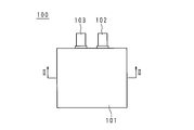
- FIG. 3 is a plan view showing a cell included in the battery according to Embodiment 1.
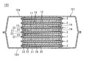
- FIG. FIG. 2 is a cross-sectional view taken along line II-II in FIG. It is a perspective view of the 1st electrode unit. It is explanatory drawing of the manufacturing procedure of a 1st electrode unit. It is explanatory drawing of the manufacturing procedure of a 1st electrode unit. It is explanatory drawing of the manufacturing procedure of a 1st electrode unit. It is explanatory drawing of the manufacturing procedure of a 1st electrode unit. It is explanatory drawing of the manufacturing procedure of a 1st electrode unit. It is explanatory drawing of the manufacturing procedure of a 1st electrode unit. It is explanatory drawing of the manufacturing procedure of a 1st electrode unit. It is explanatory drawing of the manufacturing procedure of a 1st electrode unit. It is explanatory drawing of the manufacturing procedure of a 1st electrode unit. It is explanatory drawing of the manufacturing procedure of a 1st electrode unit. It is
- FIG. 10 is a cross-sectional view of a cell included in a battery according to Embodiment 7.
- reference numeral 100 denotes a cell included in the vanadium solid salt battery.
- the vanadium solid salt battery is configured by housing one or a plurality of illustrated cells 100 in a case.
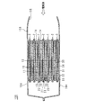
- the cell 100 includes a bag-shaped outer casing 101, and a positive terminal 102 and a negative terminal 103 protruding from the outer casing 101.
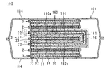
- the exterior 101 is constituted by electrolyte non-permeable films 104 and 104 in which peripheral portions of one surface are fixed to each other.
- the cell 100 includes two first electrode units 1, 1, three second electrode units 2, 2, 2, and two third electrode units 3, 3 housed in the exterior 101.
- the first electrode units 1, 1 and the second electrode units 2, 2, 2 are alternately arranged side by side in the stacking direction.
- the third electrode units 3 and 3 are located at both ends in the stacking direction, and sandwich the first electrode units 1 and 1 and the second electrode units 2, 2 and 2.
- the exterior 101 is configured by stacking two films 104 and 104 and fixing the peripheral portion as described later.
- the third electrode units 3 and 3 are adjacent to the films 104 and 104, respectively.
- the first electrode units 1, 1 and the third electrode units 3, 3 are configured as negative electrodes, and the second electrode units 2, 2, 2 are configured as positive electrodes. Accordingly, the first electrode units 1, 1, the second electrode units 2, 2, 2, and the third electrode units 3, 3 are connected in parallel.
- the cell 100 may have a configuration in which the first electrode units 1 and 1 and the third electrode units 3 and 3 are positive electrodes and the second electrode units 2, 2 and 2 are negative electrodes.
- the first electrode unit 1 includes first electrodes 10 and 10 having a rectangular flat plate shape and a first conductor 11 having a rectangular flat plate shape.
- the first electrode 10 contains an active material containing vanadium ions or ions containing vanadium and an acidic electrolytic solution.
- the first conductor 11 is provided with first coating films 12 and 12 on both surfaces.
- the first coating film 12 is conductive and non-permeable to electrolyte, and is formed by, for example, graphite coating.
- a conductive film, a sheet-like conductive rubber, a graphite sheet, or the like can be used as long as it has conductivity and electrolyte solution impermeability. .
- the first electrode unit 1 further includes a first sealant 13 that is impermeable to electrolyte solution.
- the first sealant 13 has a rectangular frame shape and is provided on the side surface side of the first conductor 11 in contact with the side surface of the first conductor 11.
- the covering films 12 and 12 are sandwiched. Further, the first sealant 13 is fixed to the peripheral portion of the surface of the first coating films 12 and 12.
- the first electrodes 10 and 10 are located inside the first sealant 13 on the surfaces of the first coating films 12 and 12, respectively. Therefore, both surfaces of the first conductor 11 are opposed to the first electrodes 10 and 10, and the first coating films 12 and 12 are formed of the first conductor 11 and the first electrodes 10 and 10, respectively. It will be provided between.
- the side surface of the first electrode 10 is surrounded by the first sealant 13.
- the side surface of the first electrode 10 may have either a configuration in contact with the first sealant 13 or a configuration in which a gap is provided without contacting the first sealant 13. Further, the first sealant 13 may not be in contact with the side surface of the first conductor 11.
- the first electrode unit 1 has first diaphragms 14 and 14.
- the first diaphragm 14 is provided on the first electrode 10.
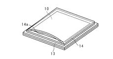
- FIG. 3 is a perspective view of the first electrode unit 1. As shown in FIG. 3, the first diaphragm 14 is fixed to a portion of the first sealant 13 that surrounds the first electrode 10 at the periphery. As a result, the first electrode 10 is entirely covered with the first coating film 12, the first sealant 13, and the first diaphragm 14. Further, the first sealant 13 and the first diaphragm 14 form an encapsulating part that encloses the first electrode 10 and the first conductor 11.
- the first electrode unit 1 has a tab (not shown) protruding from a part of the periphery of the first sealant 13. The tab is connected to the first conductor 11 and the negative terminal 103.
- the second electrode unit 2 includes square flat plate-like second electrodes 20 and 20 and a square flat plate-like second conductor 21.
- the second electrode 20 contains an active material containing vanadium ions or ions containing vanadium and an acidic electrolyte.
- the second conductor 21 is provided with second coating films 22 and 22 on both sides.
- the second coating film 22 is conductive and non-permeable to electrolyte solution, and is formed by, for example, graphite coating like the first coating film 12.
- the second electrode unit 2 further has a second sealant 23 that is impermeable to electrolyte solution.
- the second sealant 23 has a rectangular frame shape, and is provided on the side surface side of the second conductor 22 in contact with the side surface of the second conductor 22.
- the covering films 22 and 22 are sandwiched.
- the second sealant 23 is fixed to the peripheral edge of the surface of the second coating films 22 and 22.
- the second electrodes 20 and 20 are positioned inside the second sealant 23 on the surfaces of the second coating films 22 and 22, respectively. Therefore, both surfaces of the second conductor 21 face the second electrodes 20, 20, and the second coating films 22, 22 are formed between the second conductor 21 and the second electrodes 20, 20. It will be provided in between.
- the side surface of the second electrode 20 is surrounded by the second sealant 23.
- the side surface of the second electrode 20 may have either a configuration in contact with the second sealant 23 or a configuration in which a gap is provided without being in contact with the second sealant 23. Further, the second sealant 23 may not be in contact with the side surface of the second conductor 21.
- the second electrode unit 2 has a tab (not shown) that protrudes from a part of the periphery of the second sealant 23.
- the tab is connected to the second conductor 21 and the positive terminal 102. Note that the second electrode unit 2 does not have an equivalent to the diaphragm 14 in the first electrode unit 1.
- the third electrode unit 3 has a single rectangular flat third electrode 30 and a rectangular flat third conductor 31.
- the third electrode 30 contains an active material containing vanadium ions or ions containing vanadium and an acidic electrolytic solution.
- the third conductor 31 is provided with third coating films 32 and 32 on both surfaces.
- the third coating film 32 is conductive and non-permeable to electrolyte, and is formed by, for example, graphite coating, like the first coating film 12.
- the third electrode unit 3 further has a third sealant 33 that is impermeable to electrolyte solution.
- the third sealant 33 has a rectangular frame shape and is provided on the side surface side of the third conductor 31 in contact with the side surface of the third conductor 31.
- the covering films 32 and 32 are sandwiched.
- the third sealant 33 is fixed to the peripheral edge of the surface of the third coating films 32 and 32.
- the third electrode unit 3 is not limited to the configuration in which the third sealant 33 is fixed to the surfaces of the third coating films 32 and 32.
- the third sealant 33 is fixed to the peripheral portion of the surface of the third coating film 32 located on the second electrode unit 2 side and the surface of the film 104 adjacent to the third electrode unit 3. May be. In this case, the third electrode unit 3 may not have the coating film 32 on the film 104 side.
- the third electrode 30 is located inside the third sealant 33 on the third coating film 32. Accordingly, one surface of the third conductor 31 faces the third electrode 30, and the third coating film 32 is provided between the third conductor 31 and the third electrode 30. It will be.
- the side surface of the third electrode 30 is surrounded by the third sealant 33.
- the side surface of the third electrode 30 may be configured to contact the third sealant 33 or to be configured such that a gap is provided without contacting the third sealant 33. Further, the third sealant 33 may not be in contact with the side surface of the third conductor 31.
- the third electrode unit 3 has a quadrangular third diaphragm 34.
- the third diaphragm 34 is provided on the third electrode 30.
- the peripheral edge of the third diaphragm 34 is fixed to a portion of the third sealant 33 that surrounds the third electrode 30.
- the third electrode 30 is entirely covered with the third coating film 32, the third sealant 33, and the third diaphragm 34.
- the third electrode unit 3 has a tab (not shown) that protrudes from a part of the periphery of the third sealant 33.
- the tab is connected to the third conductor 31 and the negative electrode terminal 103.
- the third electrode unit 3 can be configured in the same manner as the first electrode unit 1, but is disposed at an end in the exterior 101, so that an unnecessary electrode is not disposed and a single electrode unit 3 is disposed.
- the third electrode 30 and the single third diaphragm 34 are used. Therefore, the cell 100 may have a configuration in which the first electrode unit 1 is arranged instead of the third electrode unit 3.
- the third electrode units 3 and 3 have the first electrode units 1 and 3 so that the third diaphragms 34 face each other and the second electrode units 2 and 2 face the third diaphragm 34.
- the first and second electrode units 2, 2, and 2 are sandwiched.
- the negative electrode terminal 103 to which the tabs of the first electrode units 1 and 1 and the tabs of the third electrode units 3 and 3 are connected, and the positive electrode terminal 102 to which the tabs of the second electrode units 2, 2 and 2 are connected thus, the cell 100 exchanges electrons with the outside.
- the first electrode 10, the second electrode 20, and the third electrode 30 are made of vanadium ions or vanadium on the first coating film 12, the second coating film 22, and the third coating film 32, respectively.
- a precipitate having a solid compound containing an active material containing ions is supported.
- the first electrode 10 is formed by applying an active material, a carbon material as a conductive aid, a solution containing a binder and a non-aqueous solvent, or a semi-solid material to the coating film 12 to volatilize the non-aqueous solvent. After that, it is formed by including an acidic electrolyte as described later.
- the non-aqueous solvent include N-methylpyrrolidone (NMP), methyl ethyl ketone (MEK), tetrahydrofuran (THF) and the like.
- the oxidation number of vanadium ions or ions containing vanadium contained in the active material of the second electrode 20 included in the second electrode unit 2 functioning as the positive electrode changes between pentavalent and tetravalent by an oxidation-reduction reaction. Ions containing vanadium are preferred.
- the ion containing pentavalent and tetravalent vanadium oxidation number changes between, VO 2+ (IV), VO 2 + (V) are exemplified.
- vanadium compound that is an active material for the positive electrode examples include vanadium oxide (IV) (VOSO 4 ⁇ nH 2 O) and vanadium oxide (V) ((VO 2 ) 2 SO 4 ⁇ nH 2 O). . Mixtures of these may be used.
- n is an integer of 0 to 5.
- Vanadium ions or vanadium ions contained in the active material of the first electrode 10 of the first electrode unit 1 functioning as the negative electrode and the third electrode 30 of the third electrode unit 3 are oxidized by a redox reaction. Vanadium ions whose oxidation number changes between divalent and trivalent are preferable. Examples of vanadium ions whose oxidation number varies between divalent and trivalent include V 2+ (II) and V 3+ (III).
- vanadium compound that is an active material for the negative electrode examples include vanadium sulfate (II) (VSO 4 ⁇ nH 2 O) and vanadium sulfate (III) (V 2 (SO 4 ) 3 ⁇ nH 2 O). Mixtures of these can be used.
- n is 0 or an integer of 1 to 10.
- the electrolyte contained in the first electrode 10, the second electrode 20, and the third electrode 30 is preferably an aqueous sulfuric acid solution.
- the sulfuric acid aqueous solution for example, a sulfuric acid aqueous solution having a concentration of less than 90% by mass can be used.
- the amount of the electrolytic solution is, for example, 70 mL of 2M (mol / L) sulfuric acid with respect to 100 g of the vanadium compound.
- the first diaphragm 14 and the third diaphragm 34 are ion exchange membranes through which hydrogen ions (protons) or sulfate ions can pass.
- the first conductor 11, the second conductor 21, and the third conductor 31 are preferably made of a metal foil such as aluminum or copper.
- the first sealant 13, the second sealant 23, and the third sealant 33 are preferably made of polypropylene or polyethylene. Thereby, the 1st conductor 11, the 2nd conductor 21, and the 3rd conductor 31 can be easily sealed by heat welding.
- the cell 100 is charged / discharged using the reactions of the formulas (1) and (2).
- the positive electrode terminal 102 and the negative electrode terminal 103 exchange electrons with an external load or a charger.
- protons move between the electrodes 10 and 20 via the first diaphragm 14 and protons move between the electrodes 20 and 30 via the third diaphragm 34.
- the first conductors 11 are not in direct contact with the first electrodes 10 and 10 due to the first coating films 12 and 12. Further, the side surface of the first conductor 11 and the side surface of the first electrode 10 are covered with the first sealant 13. Therefore, even if the electrolyte contained in the first electrode 10 oozes out, the electrolyte does not contact the first conductor 11, so that the corrosion of the first conductor 11 is prevented.
- first coating films 12 and 12 are conductive, the movement of electrons between the first electrodes 10 and 10 and the first conductor 11 is ensured. Similarly, the second conductor 21 and the third conductor 31 are prevented from being corroded, and movement of electrons is secured.
- first coating films 12 and 12 are disposed on both surfaces of the first conductor 11, respectively.
- the first sealant 13 has a frame shape and is fixed to the peripheral edge of the surface of the first coating films 12 and 12.
- the first diaphragm 14 is fixed to the portion of the first sealant 13 that surrounds the first electrode 10 at the periphery.
- the first electrode 10 is disposed on the first coating film 12.
- the entire first electrode 10 is covered with the first coating film 12, the first sealant 13, and the first diaphragm 14, and the electrolytic solution can be prevented from leaking outside.
- the first electrode unit 1 is configured so that the electrolytic solution does not leak out, mixing of the second electrode 20 and the third electrode 30 with the electrolytic solution in the cell 100 can be prevented.
- the first electrode 10 is covered with a first sealant 13 and a first diaphragm 14, and the first electrodes 10, 10 and the first conductor 11 are covered with the first sealant 13 and the first diaphragm. It will be enclosed in the enclosure part which 14 and 14 make. Therefore, the first electrode unit 1 can prevent leakage of the electrolyte contained in the first electrode 10 to the outside. Similarly, the third electrode unit 3 can prevent leakage of the electrolytic solution.
- the same active material can be used for the positive electrode and the negative electrode, which facilitates battery design.
- the cell 100 may constitute an iron-chromium battery in which the active material contains not vanadium ions or vanadium-containing ions but ions relating to iron or chromium.
- the electrolytic solution may be configured to be alkaline instead of acidic.
- the capacity can be increased as compared with a single electrode unit.
- the 2nd electrode unit 2 which does not have a diaphragm is used, the battery using the cell 100 and the cell 100 can be reduced in thickness.
- the third electrode 30 faces one surface of the third conductor 31. Further, an electrolyte solution impermeable third coating film 32 is disposed on the other surface of the third conductor 31. Therefore, the third conductor 31 is not corroded by the electrolytic solution from the other surface side.
- the two third electrode units 3 and 3 can be arranged in parallel as the outermost part in the stacking direction because no electrode is arranged on the other surface side of the third conductor 34, and the first electrode units arranged in parallel are arranged.
- the cell 100 can be easily assembled by covering the 1, 1 and second electrode units 2, 2, 2 and the third electrode units 3, 3 with an exterior 101.
- the cell 100 may have a configuration in which an electrolytic solution is enclosed in the exterior 101.
- the electrolytic solution eliminates the need for impregnating the second electrode 20 of the second electrode unit 2 with the electrolytic solution in advance.
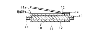
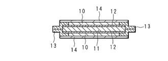
- FIG. 4A to 4E, 5A, and 5B are explanatory diagrams of the manufacturing procedure of the first electrode unit 1.
- first coating films 12 and 12 are formed on both surfaces of the first conductor 11.
- the first electrodes 10 and 10 not impregnated with the electrolytic solution are placed on the surfaces of the first coating films 12 and 12, respectively.
- 4C and 5A the side surface of the first conductor 11 is covered with the first sealant 13, and the first sealant 13 is surrounded by the first electrodes 10 and 10 so as to surround the first sealant 13.
- the coating films 12 and 12 are fixed to the peripheral edge portions of the surfaces.
- one of the first diaphragms 14 is fixed to the first sealant 13.
- the three sides of the edge portion of the first sealant 13 and the peripheral portion of the first diaphragm 14 are fixed.
- the opening 14a is formed.
- an electrolytic solution is injected from the opening 14a, and the first electrode 10 is impregnated with the electrolytic solution. Thereafter, in a reduced pressure state, one side of the edge portion of the first sealant 13 and one side of the peripheral portion of the first diaphragm 14 are fixed, and the first sealant 13 and the first diaphragm 14 are fixed.
- the first electrode unit 1 is manufactured as shown in FIG. 4E. Note that the electrolyte solution may be injected after the three sides of both the first diaphragms 14 and 14 of the first electrode unit 1 are fixed.
- FIGS. 6A to 6C are explanatory diagrams of the manufacturing procedure of the second electrode unit 2. Note that tabs are not shown in FIGS. 6A to 6C.
- second coating films 22 and 22 are formed on both surfaces of the second conductor 21.
- the second electrodes 20 and 20 not impregnated with the electrolytic solution are disposed on the surfaces of the second coating films 22 and 22, respectively.
- the side surface of the second conductor 21 is covered with the second sealant 23, and the second coating film is formed so as to surround the second electrodes 20 and 20. It adheres to the peripheral part of each 22 and 22 surface. Thereby, the 2nd electrode unit 2 is manufactured.
- the third electrode unit 3 is manufactured by the same procedure as that for the first electrode unit 1. However, the third electrode unit 3 is provided with only a single third electrode and a single third diaphragm 34.
- FIG. 7 A method for manufacturing the cell 100 will be described.
- 7, 8, 9, and 10 are explanatory diagrams of the manufacturing procedure of the cell 100.
- the first electrode unit 1, the second electrode unit 2, and the third electrode unit 3 manufactured as described above are arranged side by side as shown in FIG. In FIG. 7, the tabs are not shown.
- the first electrode units 1, 1 and the second electrode units 2, 2, 2 are alternately arranged in the stacking direction and fixed.
- the third electrode units 3 and 3 are arranged at both ends in the stacking direction and fixed to the second electrode units 2 and 2.
- the first diaphragm 14 included in the first electrode unit 1 is removed from the first diaphragm 14 except for one side or one place of the first diaphragm 14. It adheres to the 2nd sealant 23 which the electrode unit 2 has.
- the third diaphragm 34 included in the third electrode unit 3 is also fixed to the second sealant 23.
- the first electrode units 1, 1, the second electrode units 2, 2, 2 and the third electrode units 3, 3 arranged in parallel are carried into the exterior 101.
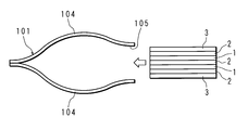
- the exterior 101 is in a state where three sides of each of the rectangular films 104 and 104 are fixed.
- an opening 105 for carrying in the first electrode units 1, 1, the second electrode units 2, 2, 2 and the third electrode units 3, 3 is formed in the exterior 101.
- the first electrode unit 1, 1, the second electrode unit 2, 2, 2, and the third electrode unit 3, 3 arranged side by side are sandwiched between two films 104, 104.
- the openings 105 may be formed by fixing the three sides 104 and 104.
- the pressure is reduced.
- An electrolytic solution is injected from the opening 105.
- the electrolyte solution is injected using, for example, a pipette. Since the electrolytic solution passes between one side or one portion where the first diaphragm 14 is not fixed and the second sealant 23, the electrode 20 of the second electrode unit 2 can be impregnated with the electrolytic solution. In addition, since the electrolytic solution passes between one side or one part where the third diaphragm 34 is not fixed and the second sealant 23, the electrode 20 of the second electrode unit 2 can be impregnated with the electrolytic solution. .
- the electrolytic solution may be injected at the same time or separately into the second electrode units 2, 2, 2.
- each of the films 104 and 104 is fixed under reduced pressure, and the opening 105 is sealed. Thereby, the cell 100 shown in FIGS. 1 and 2 is manufactured.
- the injection of the electrolytic solution from the opening 105 may not be performed in a reduced pressure state, and only the remaining side of the exterior 101 may be fixed in a reduced pressure state.
- the electrolytic solution is injected into the exterior 101 from the opening 105 after the first electrode unit 1 and the second electrode unit 2 are carried in, it is not necessary to impregnate the second electrode 20 with the electrolytic solution in advance. And the battery using the cell 1 can be assembled easily.
- the first electrode 10 and the first conductor 11 included in the first electrode unit 1 are entirely covered with the first sealant 13 and the first diaphragm 14. That is, the electrode 10 and the first conductor 11 are sealed in a sealing portion formed by the first sealant 13 and the first diaphragm 14. Therefore, the first electrode unit 1 can prevent leakage of the electrolytic solution. Therefore, the cell 100 can prevent the electrolyte solution from being mixed.
- the third electrode 30 and the third conductor 31 are covered with the third coating film 32, the third sealant 33, and the third diaphragm 34. It is possible to prevent leakage of the electrolyte.
- the first sealant 13 and the first diaphragm 14 are fixed so as to form an opening 14a, and an electrolytic solution is injected from the opening 14a. Therefore, it is not necessary to impregnate the first electrode 10 with the electrolytic solution in advance, and the electrolytic solution can be easily impregnated into the first electrode 10 by injecting the electrolytic solution. Furthermore, by closing the opening 14a after the injection of the electrolytic solution, the electrolytic solution can be enclosed and leakage from the first electrode unit 1 can be prevented. Similarly, the third electrode unit 3 can easily impregnate the third electrode 30 with the electrolytic solution to prevent leakage of the electrolytic solution.
- the first electrode unit 1 and the second electrode unit 2 can be carried in from the opening 105, and the cell 100 can be easily manufactured simply by injecting an electrolytic solution from the opening 105 after closing and closing the opening 105.
- the inside of the exterior 101 can be evacuated to maintain the quality of the cell 100 and to reduce the dimensions.
- the first electrode unit 1, the second electrode unit 2, and the third electrode unit 3 are fixed before being carried into the exterior 101, so that they can be easily carried into the exterior 101, and the cell 100 and the cell 100 A battery using can be easily assembled.
- FIG. 11 is a cross-sectional view of cell 100 included in the battery according to Embodiment 2.
- the cell 100 according to the second embodiment includes three second electrode units 2, 2, 2, two third electrode units 3, 3, and a first electrode unit 16.
- the second electrode units 2, 2, 2 and the third electrode units 3, 3 have the same configuration as in the first embodiment.
- the third electrode units 3, 3 and the first electrode unit 16 form a negative electrode, and the second electrode units 2, 2, 2 form a positive electrode. Therefore, the second electrode units 2, 2, 2, the third electrode units 3, 3, and the first electrode unit 16 are connected in parallel.
- the cell 100 may have a configuration in which the third electrode units 3 and 3 and the first electrode unit 16 form a positive electrode and the second electrode units 2, 2 and 2 form a negative electrode.
- the first electrode unit 16 sandwiches one second electrode unit 2 and is disposed between the other second electrode units 2 and 2.
- the third electrode units 3, 3 sandwich the second electrode units 2, 2, 2 and the first electrode unit 16, and are arranged at both ends of the exterior 101 side, respectively.
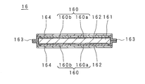
- FIG. 12 is a cross-sectional view of the first electrode unit 16. Similar to the first electrode unit 1, the first electrode unit 16 includes first electrodes 160 and 160, a rectangular flat plate-shaped first conductor 161, two first coating films 162 and 162, and a first electrode unit 16. The sealant 163 and the first diaphragms 164 and 164 are included. The first electrode 160 includes split electrodes 160 a and 160 b on a flat plate that are separated from each other in the longitudinal direction of the first conductor 161.
- the first electrode unit 16 has a tab (not shown) protruding from the first sealant 163. The tab is connected to the first conductor 161 and the negative terminal 103. In the exterior 101, the first electrode unit 16 is bent between the split electrodes 160a and 160b. Note that the first electrode 160 has two separated electrodes 160 a and 160 b, but the first electrode 160 has three or more separated electrodes in the longitudinal direction of the first conductor 161. It is good also as a structure which has a body electrode. In the configuration, the first electrode unit 1 can be arranged in the cell 100 in a zigzag shape.
- the first electrode unit 16 sandwiches the second electrode unit 2 at the bent portion.
- the materials of the first electrodes 160 and 160, the first conductor 161, the two first coating films 162 and 162, and the first sealant 163 are the same as those of the first electrode unit 1.
- the first electrode unit 16 is bent and the second electrode unit 2 is sandwiched between the bent first electrode units 16, the number of parts can be reduced, and the cell 100 Assemblability is improved.
- the first electrode unit 16 can be aligned by simply folding the first electrode unit 16 by determining the arrangement of the split electrodes 160a and 160b in advance, and the position accuracy in the cell 100 can be improved.
- FIG. 13 is a cross-sectional view of cell 100 included in the battery according to the third embodiment.
- the cell 100 includes two first electrode units 1, 1, two third electrode units 3, 3, and a second electrode unit 24.
- the first electrode unit 1, 1 and the third electrode unit 3, 3 form a negative electrode
- the second electrode unit 24 forms a positive electrode
- the first electrode units 1, 1, the third electrode units 3, 3 and the second electrode unit 24 are connected in parallel.
- the cell 100 may have a configuration in which the first electrode units 1 and 1 and the third electrode units 3 and 3 form a positive electrode and the second electrode unit 24 forms a negative electrode.
- the third electrode units 3 and 3 sandwich the first electrode units 1 and 1 and the second electrode unit 24 and are adjacent to the films 104 and 104, respectively.
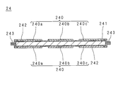
- FIG. 14 is a cross-sectional view of the second electrode unit 24.
- the second electrode unit 24 includes second electrodes 240 and 240, a rectangular flat plate-like second conductor 241, two second coating films 242 and 242, and a second electrode unit 24.
- the sealant 243 is provided.
- the second electrode 240 includes plate-like divided electrodes 240 a, 240 b, and 240 c that are separated from each other in the longitudinal direction of the second conductor 241.
- the second electrode unit 24 has a tab (not shown) protruding from the second sealant 243.
- the tab is connected to the second conductor 241 and the positive terminal 102.
- the second electrode unit 24 is bent at two places between the split electrodes 240a and 240b and between the split electrodes 240b and 240c, and has an S-shape as a whole.
- the second electrode unit 24 sandwiches the first electrode units 1 and 1 at two bent portions.
- the second electrode unit 24 is bent and the first electrode units 1 and 1 are sandwiched between the bent second electrode units 24, the number of parts can be reduced, The assembly property of the cell 100 is improved.
- the second electrode unit 24 can be positioned by simply folding the second electrode unit 24 by preliminarily arranging the split electrodes 240a, 240b, and 240c, and the positional accuracy in the cell 100 can be improved. .
- the electrode 240 was set as the structure which has the three separated electrodes 240a, 240b, 240c spaced apart in the longitudinal direction, it is good also as a structure which has the structure electrode which has two separated electrodes separated in the longitudinal direction, or four or more.
- the second electrode unit 24 can be U-shaped, and in the configuration in which the electrode 240 has four or more separated electrodes separated in the longitudinal direction, The second electrode unit 24 can be folded in a zigzag manner.
- FIG. 15 is a cross-sectional view of cell 100 included in the battery according to the fourth embodiment.
- the cell 100 according to the third embodiment includes the second electrode unit 2, the third electrode units 3 and 3, the first electrode unit 16, and the second electrode unit 25.
- the third electrode units 3 and 3 and the first electrode unit 16 form a negative electrode
- the second electrode unit 2 and the second electrode unit 25 form a positive electrode
- the third electrode units 3, 3, the first electrode unit 16, and the second electrode units 2, 25 are connected in parallel.
- the cell 100 may have a configuration in which the third electrode units 3 and 3 and the first electrode unit 16 form a positive electrode, and the second electrode unit 2 and the second electrode unit 25 form a negative electrode.
- the second electrode unit 25 has the same structure as the second electrode unit 2.
- the second electrode unit 25 includes second electrodes 250 and 250, a rectangular flat plate-like second conductor 251, two second coating films 252 and 252, and a second sealant 253.
- the second electrode 250 includes split electrodes 250 a and 250 b on a flat plate that are separated from each other in the longitudinal direction of the second conductor 251.
- the second electrode unit 25 has a tab (not shown) protruding from the second sealant 253. The tab is connected to the second conductor 251 and the positive terminal 102. In the exterior 101, the second electrode unit 25 is bent between the electrodes 250a and 250b.
- the third electrode units 3 and 3 are adjacent to the films 104 and 104, respectively, and the first electrode unit 16 and the second electrode units 2 and 25 are sandwiched between the third electrode units 3 and 3, respectively.
- the second electrode unit 25 is disposed adjacent to one third electrode unit 3, and the second electrode unit 2 is adjacent to the other third electrode unit 3. It is arranged.
- the first electrode unit 16 is disposed adjacent to the second electrode unit 2.
- first electrode unit 16 and the second electrode unit 25 are arranged to be engaged with each other so that the bent portions are located on the opposite side.
- the first electrode unit 16 and the second electrode unit 25 are bent, and the bent first electrode unit 16 and second electrode unit 25 are engaged with each other. Assembly can be performed easily.
- FIG. 16 is a cross-sectional view of cell 100 included in the battery according to Embodiment 5.
- the cell 100 according to the fifth embodiment includes five first electrode units 1, 1,... And two third electrode units 3, 3.
- the third electrode units 3 and 3 form a negative electrode, and the first electrode units 1 and 1 adjacent to the third electrode units 3 and 3 form a positive electrode.
- the first electrode units 1 and 1 adjacent to the first electrode units 1 and 1 form a negative electrode, and the remaining first electrode units 1 located in the center form a positive electrode. Accordingly, the first electrode units 1, 1,... And the third electrode units 3, 3 are connected in parallel.
- the cell 100 may be configured to be opposite to the positive electrode and the negative electrode of the five first electrode units 1, 1,... And the two third electrode units 3, 3.
- the cell 100 can be easily assembled. Further, the cell 100 can be configured in either a series or a parallel configuration.
- the third electrode unit 3 may not have the third diaphragm 34, and the third electrode unit 3 and the first electrode unit 1 may be adjacent to each other. In this configuration, the first electrode 10 and the third electrode 30 face each other with the first diaphragm 14 interposed therebetween.
- FIG. 17 is a cross-sectional view of cell 100 included in the battery according to the sixth embodiment.
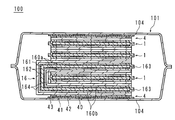
- the cell 100 according to the sixth embodiment includes three first electrode units 1, 1, 1, two fourth electrode units 4, 4 and a first electrode unit 16.
- 4th electrode unit 4 and 4 is located in the outermost part of the cell 1, and makes a negative electrode.
- the first electrode units 1 and 16 adjacent to the fourth electrode units 4 and 4 form a positive electrode.
- the first electrode unit 1 located between the first electrode units 1 and 16 forms a negative electrode.
- the remaining one first electrode unit 1 sandwiched between the first electrode units 16 forms a negative electrode. Accordingly, the first electrode units 1, 1, 1, the fourth electrode units 4, 4 and the first electrode unit 16 are connected in parallel.
- the three first electrode units 1, 1, 1, the two fourth electrode units 4, 4, and the first electrode unit 16 may have a configuration in which the positive electrode and the negative electrode are reversed.
- the fourth electrode unit 4 includes a rectangular flat plate-like fourth electrode 40 and a rectangular flat plate-like fourth conductor 41.
- the fourth electrode 40 contains an active material and an acidic electrolytic solution.
- One surface of the fourth conductor 41 is covered with a fourth coating film 42.
- the fourth coating film 42 is conductive and has no electrolyte solution permeability, and is formed, for example, by coating with graphite.
- the fourth electrode unit 4 has a fourth sealant 43 that is impermeable to electrolyte solution.
- the fourth sealant 43 has a frame shape and is provided on the side surface side of the fourth conductor 41 so as to be in contact with the side surface of the fourth conductor 41.
- the fourth sealant 43 is fixed to the peripheral edge portion of the surface of the fourth coating film 42.
- the fourth electrode 40 is located inside the fourth sealant 43 on the surface of the fourth coating film 42. Therefore, one surface of the fourth conductor 41 faces the fourth electrode 40, and the fourth coating film 42 is provided between the fourth conductor 41 and the fourth electrode 40. It becomes.
- the side surface of the fourth electrode 40 is surrounded by the fourth sealant 43.
- the side surface of the fourth electrode 40 may have either a configuration in contact with the fourth sealant 43 or a configuration in which a gap is provided without contacting the fourth sealant 43.
- the film 104 covers the other surface of the fourth conductor 41 and forms a part of the fourth electrode unit 4.
- the inner surface of the film 104 is in contact with the other surface of the fourth conductor 41.
- the film 104 is larger than the fourth conductor 41, and the area of the inner surface of the film 104 is larger than the area of the other surface of the fourth conductor 41.
- the fourth sealant 43 is fixed to the outer portion of the fourth conductor 41 on the inner surface of the film 104.
- the fourth sealant 43 is formed in a step shape corresponding to the thickness and size of the fourth electrode 40, the fourth conductor 41, and the fourth coating film 42.
- the fourth electrode unit 4 has a tab (not shown) protruding from between the fourth sealant 43 and the film 104. The tab is connected to the negative terminal 103.
- the fourth electrode units 4, 4 face the fourth electrode 40 so that the first electrode units 1, 1, 16 face the fourth electrode 40. 1 and 16 are sandwiched.
- the fourth electrode units 4 and 4 are arranged so that the inner surfaces of the respective films 104 face each other, and the peripheral portions of the inner surfaces of the respective films 104 are fixed.
- the fourth electrode unit 4 is the outermost part, the electrode units are arranged side by side, and the film 104 of the fourth electrode unit 4 is used as the outer casing 101 of the cell 100. Can be assembled.
- the cell 100 can be easily assembled.
- FIG. 18 is a cross-sectional view of cell 100 included in the battery according to the seventh embodiment.
- symbol is attached
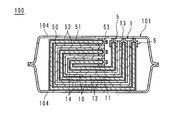
- a cell 100 according to Embodiment 7 includes a first electrode unit 1 and fifth electrode units 5 and 5.
- the first electrode unit 1 has the same configuration as that of the first embodiment.
- the first electrode unit 1 is configured as a negative electrode
- the fifth electrode unit 5 is configured as a positive electrode. Therefore, the first electrode unit 1 and the fifth electrode units 5 and 5 are connected in parallel.
- the cell 100 may have a configuration in which the first electrode unit 1 forms a positive electrode and the fifth electrode unit 5 forms a negative electrode.
- the fifth electrode unit 5 includes a square plate-like fifth electrode 50 and a square plate-like fifth conductor 51.
- the fifth electrode 50 contains an active material and an acidic electrolytic solution.
- the fifth conductor 51 is provided with fifth coating films 52 and 52 on both surfaces.
- the fifth coating film 52 is conductive and non-permeable to electrolyte, and is formed by, for example, graphite coating, like the first coating film 15.
- the fifth electrode unit 5 further includes a fifth sealant 53 that is impermeable to electrolyte solution.
- the fifth sealant 53 has a frame shape and is provided on the side surface side of the fifth conductor 51 in contact with the side surface of the fifth conductor 51.
- the fifth conductor 51 and the fifth coating The films 52 and 52 are sandwiched.
- the fifth sealant 53 is fixed to the peripheral edge of the surface of the fifth coating films 52 and 52.
- the fifth electrode 50 is located inside the fifth sealant 53 on the surface of the fifth coating film 52, respectively. Accordingly, one surface of the fifth conductor 51 faces the fifth electrode 50, and one fifth coating film 52 is provided between the fifth conductor 51 and the fifth electrode 50. Will be.
- the side surface of the fifth electrode 50 is surrounded by the fifth sealant 53.
- the side surface of the fifth electrode 50 may have either a configuration in contact with the fifth sealant 53 or a configuration in which a gap is provided without contacting the fifth sealant 53.
- the fifth electrode unit 5 has a tab (not shown) protruding from a part of the periphery of the fifth sealant 53.
- the tab is connected to the fifth conductor 51 and the positive terminal 102.
- the first electrode unit 1 is sandwiched between the fifth electrode units 5 and 5 in the stacking direction.
- the first electrode unit 1 and the fifth electrode units 5, 5 are wound in the same direction and are enclosed in the exterior 101. That is, the cell 100 has a so-called winding type.
- the first electrode 10 is covered with the first sealant 13 and the first diaphragm 14.
- the first electrode 10 is disposed on the first coating film 12. Therefore, the first electrode 10 is entirely covered with the first coating film 12, the first sealant 13, and the first diaphragm 14, and the electrolyte can be prevented from leaking outside.
- the first electrode unit 1 is configured so that the electrolytic solution does not leak out, the electrolytic solution can be prevented from mixing even in the wound cell 100 as in the first embodiment.
- the first electrode units 1, 16, the second electrode units 2, 24, 25, the third electrode unit 3, the fourth electrode unit 4, and the fifth electrode unit are not limited, and any number and juxtaposition order may be used as long as the electrodes face each other with a diaphragm interposed therebetween.
- the exterior 101 is not limited to the structure formed by fixing the film 104, and may be formed by folding a single sheet into two.
- the electrode unit according to the present invention includes a plurality of first electrodes containing an active material and an electrolytic solution, a flat conductor, and a first conductor whose both faces the first electrode.
- Conductive and electrolyte-impermeable provided between the first electrode and the first conductor, covering the both surfaces of the first conductor, and the first electrode disposed on the surface.
- Two first covering portions formed on the first electrode, the electrolyte solution non-permeable having a frame shape, surrounding the first electrode, and being fixed to a peripheral edge of the two first covering portions.
- the first conductor does not directly contact the first electrode due to the first covering portion.
- the side surface of the first conductor is covered with the first sealant. Therefore, corrosion of the first conductor due to the electrolytic solution contained in the first electrode is prevented. Since the first covering portion is conductive, movement of electrons between the first electrode and the first conductor is ensured.
- the first electrode is entirely covered with the first covering portion, the first sealant, and the first diaphragm, so that the electrolytic solution can be prevented from leaking to the outside. Therefore, the electrode unit can prevent mixing of the electrolyte solution between the electrodes of the electrode unit in the battery.
- the battery according to the present invention is characterized in that the electrode units described above are arranged in parallel in the stacking direction.
- the electrode units are arranged side by side in the stacking direction, the capacity of the battery can be increased. Moreover, since it is comprised so that the electrolyte solution of an electrode unit may not leak, mixing of the electrolyte solution of the electrodes within a battery can be prevented.
- the battery according to the present invention is characterized in that the electrode unit is bent.
- the electrode unit is bent, it becomes possible to sandwich another electrode unit between the bent electrode units, and the assembly of the battery is improved.
- a battery according to the present invention includes a plurality of second electrodes containing an active material and an electrolytic solution, a second conductor having a flat plate shape, both surfaces of which are opposed to the second electrode, and a conductive and electrolyzed battery.
- Two second electrodes that are liquid-impermeable, are provided between the second electrode and the second conductor, cover the both surfaces of the second conductor, and the second electrode is disposed on the surface.
- a coating portion of the second coating portion, and is impermeable to electrolyte, has a frame shape, surrounds the second electrode, is fixed to a peripheral edge portion of the two second coating portions, and the second coating portion
- a second electrode unit having a second sealant for sealing the second conductor is provided, and the above-described electrode unit and the second electrode unit are alternately arranged in parallel.
- the second conductor does not directly contact the second electrode due to the second covering portion.
- the side surface of the second conductor is covered with the second sealant. Therefore, corrosion of the second conductor due to the electrolytic solution contained in the second electrode is prevented. Since the second covering portion is conductive, movement of electrons between the second electrode and the second conductor is ensured. Further, since the second electrode unit having no diaphragm is used, the battery can be thinned.
- the battery according to the present invention is characterized in that the above-mentioned electrode unit is bent, and the second electrode unit is arranged while the electrode unit is bent.
- the assembly of the battery can be improved.
- the battery according to the present invention is characterized in that the second electrode unit is bent, and the electrode unit described above is arranged while the second electrode unit is bent.
- the assembly of the battery can be improved.
- the battery according to the present invention includes a third electrode containing an active material and an electrolytic solution, a third conductor having a flat plate shape, one surface facing the third electrode, a conductive and non-electrolytic solution.
- Two third electrodes that are transparent and cover both sides of the third conductor, one is provided between the third electrode and the third conductor, and the third electrode is disposed on the surface.
- Two electrode units are provided, and the two third electrode units face the third diaphragm so that the electrode units described above are provided. And wherein the I in it.
- the third conductor does not directly contact the third electrode due to the third covering portion.
- the side surface of the third conductor is covered with a third sealant. Therefore, corrosion of the third conductor is prevented. Since the third covering portion is conductive, the movement of electrons between the third electrode and the third conductor is ensured.
- the third electrode is entirely covered with the third covering portion, the third sealant, and the third diaphragm, so that the electrolyte can be prevented from leaking to the outside.
- the two third electrode units have no electrode disposed on the other surface side of the third conductor, and sandwich the above electrode unit facing the third diaphragm. Accordingly, the electrode units can be juxtaposed with the third electrode unit as the outermost part, and the battery can be easily assembled by covering the juxtaposed electrode units with the exterior.
- the battery according to the present invention includes an exterior covering the above-described electrode unit and an electrolyte solution enclosed in the exterior.
- the electrode according to the positive electrode or the negative electrode can be impregnated with the electrolyte by the electrolyte enclosed in the exterior.
- a battery according to the present invention includes a fourth electrode containing an active material and an electrolytic solution, a fourth conductor having a flat plate shape, one surface facing the fourth electrode, a conductive and non-electrolytic solution.
- a fourth covering portion that is transmissive, is provided between the fourth electrode and the fourth conductor, covers the one surface of the fourth conductor, and the fourth electrode is disposed on the surface;
- a fourth electrode unit having a fourth sealant fixed to a peripheral portion of the first electrode and having a fourth sealant surrounding the fourth electrode and sealing the fourth conductor with the film and the fourth covering portion.
- the two fourth electrode units face the fourth electrode and sandwich the electrode unit described above. Disposed in earthenware pots, the film is secured the periphery of the respective inside of the anchored the
- the fourth conductor does not directly contact the fourth electrode due to the fourth covering portion.
- the side surface of the fourth conductor is covered with the fourth sealant. Therefore, corrosion of the fourth conductor is prevented. Since the fourth covering portion is conductive, the movement of electrons between the fourth electrode and the fourth conductor is secured.
- the electrode units can be arranged side by side with the fourth electrode unit as the outermost part, and the film of the fourth electrode unit can be used as the battery exterior, the assembly of the battery is improved. Furthermore, the electrode according to the positive electrode or the negative electrode can be impregnated with the electrolytic solution sealed in the fixed film.
- the battery according to the present invention is characterized in that the active material contains vanadium ions or ions containing vanadium.
- the battery by using an active material containing vanadium ions or vanadium ions, the battery can be configured with the same active material of the positive electrode and the negative electrode, and the design of the battery is facilitated.
- a method for manufacturing a battery according to the present invention includes a plurality of first electrodes containing an active material and an electrolyte, a first conductor that has a flat plate shape and faces both sides of the first electrode, A first electrode unit that covers and encloses the first electrode and the first conductor, a plurality of second electrodes containing an active material, and a flat plate shape, both surfaces of which are the second electrodes
- a battery manufacturing method for manufacturing a battery comprising: a second electrode unit having a second conductor facing the electrode; and a bag-shaped exterior covering the first electrode unit and the second electrode unit.
- the electrolytic solution is injected after the first electrode unit and the second electrode unit are carried in, it is not necessary to impregnate the second electrode unit in advance, and the battery is easily assembled. be able to. Furthermore, since the electrode of the first electrode unit is enclosed in the enclosing portion, leakage of the electrolytic solution can be prevented and mixing with the electrolytic solution in the exterior can be prevented.
- the first electrode unit is conductive and electrolyte non-permeable, is provided between the first electrode and the first conductor, and the first conductive unit is electrically conductive.
- Two covering portions covering the both surfaces of the body and having the first electrode disposed on the surface thereof, the enclosing portion being impermeable to electrolyte, forming a frame shape,
- a sealant that is secured to a peripheral portion of the two covering portions and seals the first conductor with the covering portion; and is provided on the first electrode and the sealant.
- a step of fixing the sealant and the diaphragm so as to form an injection port for injecting the electrolytic solution, and a second injection for injecting the electrolytic solution from the injection port.
- a step of sealing the injection port after the second injection step Characterized in that it has a.
- the sealant and the diaphragm are fixed so as to form the injection port, and the electrolytic solution is injected from the injection port. Therefore, it is not necessary to impregnate the first electrode 10 with the electrolytic solution in advance, and the electrode can be easily impregnated only by injecting the electrolytic solution. Further, by closing the inlet after the injection of the electrolytic solution, the electrolytic solution can be sealed and leakage from the first electrode unit can be prevented.
- the exterior is configured by two opposing films, and the first electrode unit and the second electrode unit are carried in before the carrying-in step. It has the process of adhering the peripheral part of each of the said 2 film so that a carrying-in entrance may be formed.
- the first electrode unit and the second electrode unit can be carried in from the carry-in port, and the battery can be easily manufactured by injecting the electrolyte solution from the carry-in port after the carry-in and closing the carry-in port. it can.
- the battery manufacturing method according to the present invention is characterized by having a step of sealing the carry-in port of the exterior in a reduced pressure state after the first injection step.
- the inside of the exterior can be evacuated to maintain the quality of the battery and reduce the size.
- the battery manufacturing method according to the present invention is characterized in that it has a fixing step of fixing the first electrode unit and the second electrode unit before the carrying-in step.
- the first electrode unit and the second electrode unit are fixed before the carrying-in process, so that they can be carried into the exterior easily.
Landscapes
- Chemical & Material Sciences (AREA)
- Chemical Kinetics & Catalysis (AREA)
- Electrochemistry (AREA)
- General Chemical & Material Sciences (AREA)
- Engineering & Computer Science (AREA)
- Manufacturing & Machinery (AREA)
- Inorganic Chemistry (AREA)
- Sealing Battery Cases Or Jackets (AREA)
Abstract
電極ユニットの電解液の漏れ出しを防止し、電極同士の電解液の混合を防止することができる電極ユニット、電池及び電池の製造方法を提供する。電極ユニット1は、活物質、及び電解液を含有する第1の電極10,10と、平板状をなし、両面が第1の電極10に対向する第1の導電体11と、導電性かつ電解液非透過性であり、第1の電極10及び第1の導電体11間に設けられ、第1の導電体11の両面を覆い、表面に第1の電極10が配される第1の被覆部12,12と、電解液非透過性であり、額縁状をなし、第1の電極10を囲み、第1の被覆部12,12の周縁部に固着され、第1の被覆部12とにより第1の導電体11を封止する第1のシーラント13と、第1の電極10及び第1のシーラント13上に設けられ、第1のシーラント13に固着された第1の隔膜14とを備える。
Description
本発明は、電極及び導電体を有する電極ユニット、電池及び電池の製造方法に関する。
電池は、デジタル家電製品、電気自動車、ハイブリッド自動車及び太陽光発電設備等に広く用いられている。この電池として、バナジウム固体塩電池等が挙げられる(例えば、特許文献1参照)。
バナジウム固体塩電池は、セルをケースに収容することにより構成される。セルは、積層方向に並設された複数の電極ユニット及び該複数の電極ユニットを覆う外装を備える。電極ユニットは、電極及び導電体を有している。電極は、多孔質の炭素材と、該炭素材が含有するバナジウムイオン又はバナジウムを含むイオンを含有する活物質と、電解液とを有する。
バナジウム固体塩電池では、複数の電極ユニットが、隔膜を介して各々の電極ユニットが有する電極を対向させて、並設されている。隔膜を介して複数の電極ユニットを並設することにより、一の電極ユニットが有する正極に係る電極及び隣り合う他の電極ユニットが有する負極に係る電極夫々の電解液が混合し、電池の性能が低下することを防止している。バナジウム固体塩電池は、正極に係る電極及び負極に係る電極間における酸化還元反応を利用して充放電を行う。
しかしながら、正極に係る電極及び負極に係る電極の間に、単純に隔膜を設けるだけでは、電解液の混合の対策として十分でない。
本発明は、斯かる事情に鑑みてなされたものであり、その目的とするところは、電極ユニットの電解液の漏れ出しを防止し、電極同士の電解液の混合を防止することができる電極ユニット、電池及び電池の製造方法を提供することにある。
本発明に係る電極ユニットは、活物質、及び電解液を含有する複数の第1の電極と、平板状をなし、両面が前記第1の電極に対向する第1の導電体と、導電性かつ電解液非透過性であり、前記第1の電極及び第1の導電体間に設けられ、前記第1の導電体の前記両面を覆い、表面に前記第1の電極が配される二つの第1の被覆部と、電解液非透過性であり、額縁状をなし、前記第1の電極を囲み、前記二つの第1の被覆部の周縁部に固着され、前記第1の被覆部とにより前記第1の導電体を封止する第1のシーラントと、前記第1の電極及び第1のシーラント上に設けられ、前記第1のシーラントに固着された第1の隔膜とを備えることを特徴とする。
本発明に係る電池の製造方法は、活物質、及び電解液を含有する複数の第1の電極と、平板状をなし、両面が前記第1の電極に対向する第1の導電体と、前記第1の電極及び第1の導電体を覆い、封入する封入部とを有する第1の電極ユニット、活物質を含有する複数の第2の電極と、平板状をなし、両面が前記第2の電極に対向する第2の導電体とを有する第2の電極ユニット、及び前記第1の電極ユニットと第2の電極ユニットとを覆う袋状の外装を備える電池を製造する電池の製造方法であって、前記外装の内部に前記第1の電極ユニットと第2の電極ユニットとを搬入する搬入工程と、該搬入工程の後、前記第2の電極ユニットに含有させるべき電解液を前記外装の内部に注入する第1の注入工程とを有することを特徴とする。
本発明によれば、電極ユニットの電解液の漏れ出しを防止し、電極同士の電解液の混合を防止することができる。
以下、本発明をその実施の形態を示す図面に基づいて詳述する。
(実施の形態1)
図1において、100はバナジウム固体塩電池が備えるセルである。バナジウム固体塩電池は、図示のセル100を一つ又は複数個ケースに収容することにより構成されている。セル100は袋状の外装101と、該外装101から突出した正極端子102及び負極端子103とを備える。
(実施の形態1)
図1において、100はバナジウム固体塩電池が備えるセルである。バナジウム固体塩電池は、図示のセル100を一つ又は複数個ケースに収容することにより構成されている。セル100は袋状の外装101と、該外装101から突出した正極端子102及び負極端子103とを備える。
外装101は、図2に示すように一面の周縁部が互いに固着された電解液非透過性のフィルム104,104により構成されている。
セル100は、外装101の内部に収容された二つの第1の電極ユニット1,1、三つの第2の電極ユニット2,2,2、及び二つの第3の電極ユニット3,3を備える。第1の電極ユニット1,1及び第2の電極ユニット2,2,2は、積層方向に交互に並設され、隣接している。
第3の電極ユニット3,3は、前記積層方向の両端に位置し、第1の電極ユニット1,1及び第2の電極ユニット2,2,2を挟んである。また、外装101は、二枚のフィルム104,104を重ね、周縁部を後述の如く固着して構成されている。第3の電極ユニット3,3は、夫々フィルム104,104に隣接している。
第1の電極ユニット1,1及び第3の電極ユニット3,3は、負極をなし、第2の電極ユニット2,2,2は正極をなすように構成されている。したがって、第1の電極ユニット1,1、第2の電極ユニット2,2,2、及び第3の電極ユニット3,3は並列に接続されることとなる。なお、セル100は、第1の電極ユニット1,1及び第3の電極ユニット3,3を正極とし、第2の電極ユニット2,2,2を負極とする構成であってもよい。
第1の電極ユニット1は、四角形平板状の第1の電極10,10と、四角形平板状の第1の導電体11とを有する。第1の電極10は、バナジウムイオン又はバナジウムを含むイオンを含有する活物質及び酸性の電解液を含有する。第1の導電体11は、両面に第1の被覆膜12,12が設けられている。第1の被覆膜12は、導電性かつ電解液非透過性であり、例えば黒鉛コーティングにより形成される。
また、第1の被覆膜12に代えて、導電性かつ電解液非透過性を有していれば、導電性フィルム、シート状の導電性ゴム、グラファイトシート等を用いる構成とすることができる。例えば、グラファイトシートを導電性を有する接着シートを介して、第1の導電体11の一面又は両面に配する構成としてもよい。
第1の電極ユニット1は、更に電解液非透過性の第1のシーラント13を有する。第1のシーラント13は、四角形額縁状をなし、第1の導電体11の側面に接触する状態で第1の導電体11の側面側に設けられ、第1の導電体11及び第1の被覆膜12,12を挟んでいる。また、第1のシーラント13は、第1の被覆膜12,12の表面の周縁部に固着されている。
第1の電極10,10は、夫々第1の被覆膜12,12の表面にて、第1のシーラント13の内側に位置している。したがって、第1の導電体11の両面は、第1の電極10,10に対向し、第1の被覆膜12,12は、夫々第1の導電体11と第1の電極10,10との間に設けられていることとなる。
また、第1の電極10の側面は、第1のシーラント13に囲まれている。なお、第1の電極10の側面は、第1のシーラント13に接触する構成、又は第1のシーラント13に接触せず隙間が設けられている構成のいずれであってもよい。また、第1のシーラント13は第1の導電体11の側面に接触していない構成であってもよい。
更に、第1の電極ユニット1は、第1の隔膜14,14を有する。第1の隔膜14は第1の電極10上に設けられている。図3は、第1の電極ユニット1の斜視図である。図3に示すように、第1の隔膜14は、周縁部にて四辺が第1のシーラント13における第1の電極10を囲う部分に固着されている。これにより、第1の電極10は、第1の被覆膜12、第1のシーラント13及び第1の隔膜14に、全体を覆われることになる。また、第1のシーラント13及び第1の隔膜14は、第1の電極10及び第1の導電体11を封入する封入部をなす。
また、第1の電極ユニット1は、第1のシーラント13の周縁の一部から突出するタブ(不図示)を有する。該タブは、第1の導電体11及び負極端子103に接続されている。
第2の電極ユニット2は、四角形平板状の第2の電極20,20と、四角形平板状の第2の導電体21とを有する。第2の電極20は、バナジウムイオン又はバナジウムを含むイオンを含有する活物質及び酸性の電解液を含有する。第2の導電体21は、両面に第2の被覆膜22,22が設けられている。第2の被覆膜22は、導電性かつ電解液非透過性であり、第1の被覆膜12同様、例えば黒鉛コーティングにより形成される。
第2の電極ユニット2は、更に電解液非透過性の第2のシーラント23を有する。第2のシーラント23は、四角形額縁状をなし、第2の導電体22の側面に接触する状態で第2の導電体22の側面側に設けられ、第2の導電体21及び第2の被覆膜22,22を挟んでいる。また、第2のシーラント23は、第2の被覆膜22,22の表面の周縁部に固着されている。
第2の電極20,20は、夫々第2の被覆膜22,22の表面にて、第2のシーラント23の内側に位置している。したがって、第2の導電体21の両面は、第2の電極20,20に対向し、第2の被覆膜22,22は、第2の導電体21と第2の電極20,20との間に設けられていることとなる。
また、第2の電極20の側面は、第2のシーラント23に囲まれている。なお、第2の電極20の側面は、第2のシーラント23に接触する構成、又は第2のシーラント23に接触せず隙間が設けられている構成のいずれであってもよい。また、第2のシーラント23は第2の導電体21の側面に接触していない構成であってもよい。
また、第2の電極ユニット2は、第2のシーラント23の周縁の一部から突出するタブ(不図示)を有する。該タブは、第2の導電体21及び正極端子102に接続されている。なお、第2の電極ユニット2は、第1の電極ユニット1における隔膜14に相当するものを有していない。
第3の電極ユニット3は、四角形平板状の単一の第3の電極30と、四角形平板状の第3の導電体31とを有する。第3の電極30は、バナジウムイオン又はバナジウムを含むイオンを含有する活物質及び酸性の電解液を含有する。第3の導電体31は、両面に第3の被覆膜32,32が設けられている。第3の被覆膜32は、導電性かつ電解液非透過性であり、第1の被覆膜12同様、例えば黒鉛コーティングにより形成される。
第3の電極ユニット3は、更に電解液非透過性の第3のシーラント33を有する。第3のシーラント33は、四角形額縁状をなし、第3の導電体31の側面に接触する状態で第3の導電体31の側面側に設けられ、第3の導電体31及び第3の被覆膜32,32を挟んでいる。また、第3のシーラント33は、第3の被覆膜32,32の表面の周縁部に固着されている。なお、第3の電極ユニット3は、第3のシーラント33が第3の被覆膜32,32夫々の表面に固着されている構成に限られない。例えば、第3のシーラント33は、第2の電極ユニット2側に位置する第3の被覆膜32の表面の周縁部と、前記第3の電極ユニット3に隣接するフィルム104の表面とに固着されていてもよい。この場合、第3の電極ユニット3は、フィルム104側の被覆膜32を有していなくともよい。
第3の電極30は、第3の被覆膜32上にて、第3のシーラント33の内側に位置している。したがって、第3の導電体31の一面は、第3の電極30に対向し、第3の被覆膜32は、第3の導電体31と第3の電極30との間に設けられていることとなる。
また、第3の電極30の側面は、第3のシーラント33に囲まれている。なお、第3の電極30の側面は、第3のシーラント33に接触する構成、又は第3のシーラント33に接触せず隙間が設けられている構成のいずれであってもよい。また、第3のシーラント33は第3の導電体31の側面に接触していない構成であってもよい。
更に、第3の電極ユニット3は、四角形状の第3の隔膜34を有する。第3の隔膜34は第3の電極30上に設けられている。第3の隔膜34の周縁部は、第3のシーラント33における第3の電極30を囲う部分に固着されている。これにより、第3の電極30は、第3の被覆膜32、第3のシーラント33及び第3の隔膜34に、全体を覆われることになる。
また、第3の電極ユニット3は、第3のシーラント33の周縁の一部から突出するタブ(不図示)を有する。該タブは、第3の導電体31及び負極端子103に接続されている。
なお、第3の電極ユニット3は、第1の電極ユニット1と同様の構成を可能とするが、外装101内において端部に配されているので、必要のない電極を配さず、単一の第3の電極30及び単一の第3の隔膜34のみを有する構成としている。したがって、セル100は、第3の電極ユニット3に代えて、第1の電極ユニット1を配する構成であってもよい。
また、第3の電極ユニット3,3は、夫々の第3の隔膜34を対向させ、第3の隔膜34に第2の電極ユニット2,2が面するように、第1の電極ユニット1,1及び第2の電極ユニット2,2,2を挟んでいる。
第1の電極ユニット1,1夫々のタブ及び第3の電極ユニット3,3のタブが接続された負極端子103、第2の電極ユニット2,2,2夫々のタブが接続された正極端子102によりセル100は外部と電子のやり取りが行われる。
以下、本発明に係るセル100を構成する材料について詳述する。第1の電極10、第2の電極20及び第3の電極30は、夫々第1の被覆膜12、第2の被覆膜22及び第3の被覆膜32に、バナジウムイオン又はバナジウムを含むイオンを含有する活物質を含む固体状の化合物を有する析出物を担持させてなる。
例えば、第1の電極10は、活物質、導電助剤としての炭素材料、バインダ及び非水系溶媒を含有する溶液又は半固体状物等を被覆膜12に塗布し、非水系溶媒を揮発させた後、後述するように酸性の電解液を含ませることにより形成される。非水系溶媒としては、N-メチルピロリドン(NMP)、メチルエチルケトン(MEK)、テトラヒドロフラン(THF)等が例示される。
正極として機能する第2の電極ユニット2が有する第2の電極20の活物質に含まれるバナジウムイオン又はバナジウムを含むイオンは、酸化還元反応によって、5価及び4価の間で酸化数が変化するバナジウムを含むイオンであるのが好ましい。5価及び4価の間で酸化数が変化するバナジウムを含むイオンとしては、VO2+(IV)、VO2
+(V )が例示される。
正極用の活物質であるバナジウム化合物は、酸化硫酸バナジウム(IV)(VOSO4 ・nH2 O)、酸化硫酸バナジウム(V )((VO2 )2 SO4 ・nH2 O)を挙げることができる。これらの混合物を用いてもよい。nは、0~5の整数である。
負極として機能する第1の電極ユニット1が有する第1の電極10及び第3の電極ユニット3が有する第3の電極30の活物質に含まれるバナジウムイオン又はバナジウムを含むイオンは、酸化還元反応によって、2価及び3価の間で酸化数が変化するバナジウムイオンであるのが好ましい。2価及び3価の間で酸化数が変化するバナジウムイオンとしては、V2+(II)、V3+(III )が例示される。
負極用の活物質であるバナジウム化合物としては、硫酸バナジウム(II)(VSO4 ・nH2 O)、硫酸バナジウム(III )(V2 (SO4 )3 ・nH2 O)が挙げられる。これらの混合物が用いられ得る。nは、0又は1~10の整数である。
また、第1の電極10、第2の電極20及び第3の電極30に含まれる電解液は、硫酸水溶液であるのが好ましい。硫酸水溶液として、例えば濃度が90質量%未満の硫酸水溶液を用いることができる。電解液の量は、例えばバナジウム化合物100gに対して、2M(mol/L)の硫酸70mLである。
第1の隔膜14を隔てて対向する第1の電極10及び第2の電極20間と、第3の隔膜34を隔てて対向する第2の電極20及び第3の電極30間とにおいて、夫々下記式(1)及び(2)の反応が生じる。
正極:VOX2 ・nH2 O(s)⇔VO2 X・(n-1)H2 O(s)+HX+H+ +e- …(1)
負極:VX3 ・nH2 O(s)+H+ +e- ⇔VX2 ・nH2 O(s)+HX…(2)
式中、Xは1価の陰イオンを表す。Xがm価の陰イオンである場合、結合係数(1/m)が考慮される。nは、バナジウム化合物に対応する種々の値をとり得る。
正極:VOX2 ・nH2 O(s)⇔VO2 X・(n-1)H2 O(s)+HX+H+ +e- …(1)
負極:VX3 ・nH2 O(s)+H+ +e- ⇔VX2 ・nH2 O(s)+HX…(2)
式中、Xは1価の陰イオンを表す。Xがm価の陰イオンである場合、結合係数(1/m)が考慮される。nは、バナジウム化合物に対応する種々の値をとり得る。
第1の隔膜14及び第3の隔膜34は、水素イオン(プロトン)又は硫酸イオンを通過させることができるイオン交換膜である。第1の導電体11、第2の導電体21及び第3の導電体31は、アルミニウム又は銅等の金属箔からなるのが好ましい。
第1のシーラント13、第2のシーラント23及び第3のシーラント33は、ポリプロピレン又はポリエチレン等を用いることが好ましい。これにより、熱溶着で容易に第1の導電体11、第2の導電体21及び第3の導電体31を封止できる。
式(1)及び(2)の反応を利用してセル100の充放電が行われる。このとき、正極端子102及び負極端子103により、外部の負荷又は充電器等との電子のやり取りが行われる。式(1)及び(2)の反応において第1の隔膜14を介して電極10、20間でプロトンが移動し、第3の隔膜34を介して電極20、30間でプロトンが移動する。
上記の構成によれば、第1の被覆膜12,12により、第1の導電体11は、第1の電極10,10に直接接触しない。また、第1の導電体11の側面及び第1の電極10の側面は第1のシーラント13に覆われている。したがって、第1の電極10に含まれる電解液がしみ出したとしても、電解液が第1の導電体11に接触しないので、第1の導電体11の腐食が防止される。
第1の被覆膜12,12は導電性であるので、第1の電極10,10及び第1の導電体11間の電子の移動が担保されている。第2の導電体21及び第3の導電体31も同様に腐食が防止され、電子の移動が担保されている。
また、第1の導電体11の両面夫々に、第1の被覆膜12,12が配されている。第1のシーラント13は、額縁状をなし、第1の被覆膜12,12の表面の周縁部に固着されている。第1の隔膜14は、周縁部が第1のシーラント13における第1の電極10を囲う部分に固着されている。また、第1の電極10は第1の被覆膜12上に配されている。
したがって、第1の電極10は、第1の被覆膜12、第1のシーラント13及び第1の隔膜14により全体を覆われることとなり、電解液が外部に漏れ出すことを防止できる。
第1の電極ユニット1は、電解液が漏れ出さないように構成されているため、セル100内で第2の電極20及び第3の電極30の電解液との混合を防止できる。
また、第1の電極10は、第1のシーラント13及び第1の隔膜14に覆われ、第1の電極10,10及び第1の導電体11は、第1のシーラント13及び第1の隔膜14,14がなす封入部に封入されることとなる。したがって、第1の電極ユニット1は、第1の電極10に含まれる電解液の外部への漏出を防止できる。また、第3の電極ユニット3も同様に電解液の漏出を防止できる。
バナジウムイオン又はバナジウムを含むイオンを含有する活物質を用いることにより正極及び負極において同一の活物質を用いることができ、電池の設計が容易となる。また、セル100は、活物質がバナジウムイオン又はバナジウムを含むイオンでなく、鉄又はクロムに係るイオンを含有する鉄-クロム系電池を構成してもよい。更に、電解液は、酸性でなくアルカリ性とする構成であってもよい。
複数の電極ユニットが積層方向に並設されているので電極ユニットが単一の場合より容量を増大できる。また、隔膜を有しない第2の電極ユニット2を用いるので、セル100及びセル100を用いた電池を薄型化することができる。
第3の電極ユニット3においては、第3の導電体31の一面に第3の電極30が対向している。また、第3の導電体31の他面には、電解液非透過性の第3の被覆膜32が配されている。したがって、該第3の導電体31は、他面側から電解液により腐食されない。
また、二つの第3の電極ユニット3,3は、第3の導電体34の他面側に電極が配されていないので積層方向の最外部として並設でき、並設した第1の電極ユニット1,1及び第2の電極ユニット2,2,2及び第3の電極ユニット3,3を外装101で覆うことにより容易にセル100を組み立てることができる。
なお、セル100は、外装101内に電解液を封入する構成であってもよい。該電解液により、第2の電極ユニット2の第2の電極20に予め電解液を含浸させておく必要がなくなる。
第1の電極ユニット1の製造方法について説明する。図4A~図4E、図5A及び図5Bは、第1の電極ユニット1の製造手順の説明図である。なお、図4A~図4E、図5A及び図5Bにおいてタブの図示は省略している。まず、図4Aに示すように、第1の導電体11の両面夫々に第1の被覆膜12,12を形成する。
次に、図4Bに示すように、電解液を含浸させていない第1の電極10,10を夫々、第1の被覆膜12,12の表面に載置する。そして、図4C及び図5Aに示すように、第1の導電体11の側面を第1のシーラント13で覆い、該第1のシーラント13を第1の電極10,10を囲むように第1の被覆膜12,12夫々の表面の周縁部に固着する。
その後、一方の第1の隔膜14を第1のシーラント13に固着する。このとき、図5Bに示すように、第1のシーラント13の縁部分及び第1の隔膜14の周縁部において、夫々の三辺を固着する。これにより、第1のシーラント13の縁部分及び第1の隔膜14の周縁部において、一辺のみが固着されていないこととなり、開口14aが形成される。
図4Dに示すように、開口14aから電解液を注入し、電解液を第1の電極10に含浸させる。その後、減圧状態で第1のシーラント13の縁部分の一辺及び第1の隔膜14の周縁部の一辺を固着し、第1のシーラント13及び第1の隔膜14を固着する。同様の手順により、他方の第1の隔膜14を第1のシーラント13に固着することにより、図4Eに示すように第1の電極ユニット1が製造される。なお、第1の電極ユニット1の両方の第1の隔膜14,14夫々の三辺を固着した後に、電解液を注入してもよい。
第2の電極ユニット2の製造方法について説明する。図6A~図6Cは、第2の電極ユニット2の製造手順の説明図である。なお、図6A~図6Cにおいてタブの図示は省略している。まず、図6Aに示すように、第2の導電体21の両面夫々に第2の被覆膜22,22を形成する。
次に、図6Bに示すように、電解液を含浸させていない第2の電極20,20を夫々、第2の被覆膜22,22の表面に配する。そして、図6Cに示すように、第2の導電体21の側面を第2のシーラント23で覆い、該第2のシーラント23を第2の電極20,20を囲むように第2の被覆膜22,22夫々の表面の周縁部に固着する。これにより、第2の電極ユニット2が製造される。
第3の電極ユニット3は、第1の電極ユニット1と同様の手順により製造される。ただし、第3の電極ユニット3は、単一の第3の電極及び単一の第3の隔膜34のみが配される。
セル100の製造方法について説明する。図7、図8、図9及び図10は、セル100の製造手順の説明図である。まず、上記の如く製造された第1の電極ユニット1、第2の電極ユニット2及び第3の電極ユニット3を図7に示すように並設し、固着する。なお、図7おいては、タブの図示を省略している。
このとき、第1の電極ユニット1,1及び第2の電極ユニット2,2,2を積層方向に交互に並設し、固着する。第3の電極ユニット3,3を積層方向の両端に配し、第2の電極ユニット2,2に固着する。第1の電極ユニット1及び第2の電極ユニット2の固着においては、第1の電極ユニット1が有する第1の隔膜14を、該第1の隔膜14の一辺又は一箇所を除いて第2の電極ユニット2が有する第2のシーラント23に固着する。また、第3の電極ユニット3が有する第3の隔膜34も同様に第2のシーラント23に固着される。
次に、図8に示すように、並設された第1の電極ユニット1,1、第2の電極ユニット2,2,2及び第3の電極ユニット3,3を外装101内に搬入する。このとき、外装101は、図9に示すように、四角形状のフィルム104,104夫々の三辺が固着された状態である。これにより、外装101にて、第1の電極ユニット1,1、第2の電極ユニット2,2,2及び第3の電極ユニット3,3の搬入を行う開口105が形成される。なお、並設された第1の電極ユニット1,1、第2の電極ユニット2,2,2及び第3の電極ユニット3,3を二枚のフィルム104,104で挟んだ状態で、該フィルム104,104夫々の三辺を固着して開口105を形成してもよい。
開口105から、固着された第1の電極ユニット1,1、第2の電極ユニット2,2,2及び第3の電極ユニット3,3を搬入した後、減圧状態で、図10に示すように開口105から電解液を注入する。電解液の注入は、例えばピペットを用いて行われる。電解液が第1の隔膜14の固着されていない一辺又は一箇所と第2のシーラント23の間を通過するので、第2の電極ユニット2の電極20に電解液を含浸させることができる。また、電解液が第3の隔膜34の固着されていない一辺又は一箇所と第2のシーラント23の間を通過するので、第2の電極ユニット2の電極20に電解液を含浸させることができる。なお、電解液の注入は、第2の電極ユニット2,2,2に対して同時、又は各別に注入する構成その他の構成のいずれであってもよい。
その後、フィルム104,104夫々の残りの一辺を減圧状態で固着し、開口105を封止する。これにより、図1及び図2に示すセル100が製造される。なお、開口105からの電解液の注入を減圧状態で行わず、外装101の残りの一辺の固着のみを減圧状態で行ってもよい。
第1の電極ユニット1及び第2の電極ユニット2の搬入後に電解液を開口105から外装101内に注入するので、第2の電極20に予め電解液を含浸させておく必要がなく、セル1及びセル1を用いた電池を容易に組み立てることができる。
更に、第1の電極ユニット1が有する第1の電極10及び第1の導電体11は、全体を第1のシーラント13及び第1の隔膜14に覆われることとなる。即ち、電極10及び第1の導電体11は、第1のシーラント13及び第1の隔膜14がなす封入部に封入される。したがって、第1の電極ユニット1は、電解液の漏出を防止できる。したがって、セル100は電解液の混合を防止できる。また、第3の電極ユニット3において、第3の電極30及び第3の導電体31は、第3の被覆膜32、第3のシーラント33及び第3の隔膜34に覆われているので、電解液の漏出を防止できる。
第1のシーラント13及び第1の隔膜14が開口14aを形成するように固着され、該開口14aから電解液が注入される。したがって、予め第1の電極10に電解液の含浸をさせる必要がなく、電解液の注入により第1の電極10への電解液の含浸を容易に行うことができる。更に、電解液の注入後に開口14aを閉じることにより、電解液を封入し、第1の電極ユニット1からの漏出を防止できる。また第3の電極ユニット3も同様に容易に第3の電極30に電解液を含浸させ、電解液の漏出を防止できる。
開口105から、第1の電極ユニット1及び第2の電極ユニット2を搬入でき、搬入後に開口105から電解液を注入し、開口105を閉じるだけで容易にセル100を作製することができる。外装101の内部を真空状態にし、セル100の品質を保ち、また寸法を小さくできる。
外装101内への搬入前に第1の電極ユニット1、第2の電極ユニット2及び第3の電極ユニット3を固着しておくことで、外装101内に容易に搬入でき、セル100及びセル100を用いた電池を容易に組み立てることができる。
(実施の形態2)
図11は、実施の形態2に係る電池が備えるセル100の断面図である。実施の形態2に係る電池が備えるセル100の構成について、実施の形態1と同様な構成については、同一の符号を付してその詳細な説明を省略する。実施の形態2に係るセル100は、三つの第2の電極ユニット2,2,2、二つの第3の電極ユニット3,3及び第1の電極ユニット16を備える。第2の電極ユニット2,2,2及び第3の電極ユニット3,3は実施の形態1と同様の構成である。
図11は、実施の形態2に係る電池が備えるセル100の断面図である。実施の形態2に係る電池が備えるセル100の構成について、実施の形態1と同様な構成については、同一の符号を付してその詳細な説明を省略する。実施の形態2に係るセル100は、三つの第2の電極ユニット2,2,2、二つの第3の電極ユニット3,3及び第1の電極ユニット16を備える。第2の電極ユニット2,2,2及び第3の電極ユニット3,3は実施の形態1と同様の構成である。
第3の電極ユニット3,3及び第1の電極ユニット16は、負極をなし、第2の電極ユニット2,2,2は正極をなす。したがって、第2の電極ユニット2,2,2、第3の電極ユニット3,3及び第1の電極ユニット16は並列に接続されている。なお、セル100は、第3の電極ユニット3,3及び第1の電極ユニット16が正極をなし、第2の電極ユニット2,2,2が負極をなす構成であってもよい。
第1の電極ユニット16は一の第2の電極ユニット2を挟んであり、他の第2の電極ユニット2,2に挟まれた状態で配されている。第3の電極ユニット3,3は、第2の電極ユニット2,2,2、及び第1の電極ユニット16を挟んであり、夫々外装101側両端に配されている。
図12は、第1の電極ユニット16の断面図である。第1の電極ユニット16は、第1の電極ユニット1と同様に第1の電極160,160、矩形平板状の第1の導電体161、二つの第1の被覆膜162,162及び第1のシーラント163及び第1の隔膜164,164を有する。第1の電極160は、第1の導電体161の長手方向に離隔する平板上の分体電極160a及び160bを有する。
第1の電極ユニット16は、第1のシーラント163から突出するタブ(不図示)を有する。タブは、第1の導電体161及び負極端子103に接続されている。外装101内において、第1の電極ユニット16は、分体電極160a、160bの間にて折り曲げられている。なお、第1の電極160は離隔した二個の分体電極160a、160bを有する構成であるが、第1の電極160は、第1の導電体161の長手方向に離隔した三個以上の分体電極を有する構成としてもよい。該構成においては、第1の電極ユニット1をつづら折り状にしてセル100内に配することができる。
図11に示すように、第1の電極ユニット16は、折り曲げられた部分にて、第2の電極ユニット2を挟んでいる。
第1の電極160,160、第1の導電体161、二つの第1の被覆膜162,162及び第1のシーラント163の材質は、第1の電極ユニット1と同様である。
上記の構成によれば、第1の電極ユニット16が折り曲げられ、折り曲げられた第1の電極ユニット16の間に第2の電極ユニット2を挟んでいるので、部品点数を削減でき、セル100の組み立て性が向上する。
また、第1の電極ユニット16は、分体電極160a及び160bの配置を予め定めておくことで、折り曲げるだけで位置合わせをすることができ、セル100内における位置精度を高めることができる。
(実施の形態3)
図13は、実施の形態3に係る電池が備えるセル100の断面図である。実施の形態3に係る電池が備えるセル100の構成について、実施の形態1と同様な構成については、同一の符号を付してその詳細な説明を省略する。セル100は、二つの第1の電極ユニット1,1、二つの第3の電極ユニット3,3及び第2の電極ユニット24を備える。
図13は、実施の形態3に係る電池が備えるセル100の断面図である。実施の形態3に係る電池が備えるセル100の構成について、実施の形態1と同様な構成については、同一の符号を付してその詳細な説明を省略する。セル100は、二つの第1の電極ユニット1,1、二つの第3の電極ユニット3,3及び第2の電極ユニット24を備える。
第1の電極ユニット1,1及び第3の電極ユニット3,3は、負極をなし、第2の電極ユニット24は正極をなす。したがって、第1の電極ユニット1,1、第3の電極ユニット3,3及び第2の電極ユニット24は並列に接続されている。なお、セル100は、第1の電極ユニット1,1及び第3の電極ユニット3,3が正極をなし、第2の電極ユニット24が負極をなす構成であってもよい。
第3の電極ユニット3,3は、第1の電極ユニット1,1及び第2の電極ユニット24を挟んであり、夫々フィルム104,104に隣接している。
図14は、第2の電極ユニット24の断面図である。第2の電極ユニット24は、第2の電極ユニット2と同様に第2の電極240,240、矩形平板状の第2の導電体241、二つの第2の被覆膜242,242及び第2のシーラント243を有する。第2の電極240は、第2の導電体241の長手方向に離隔する平板状の分体電極240a、240b、240cを有する。
第2の電極ユニット24は、第2のシーラント243から突出するタブ(不図示)を有する。タブは、第2の導電体241及び正極端子102に接続されている。外装101内において、第2の電極ユニット24は、分体電極240a及び240bの間と、分体電極240b及び240cの間の二箇所にて折り曲げられ、全体としてS字状をなしている。
図13に示すように、第2の電極ユニット24は、折り曲げられた二箇所夫々にて、第1の電極ユニット1,1を挟んでいる。
上記の構成によれば、第2の電極ユニット24が折り曲げられ、折り曲げられた第2の電極ユニット24の間にて第1の電極ユニット1,1を挟んでいるので、部品点数を削減でき、セル100の組み立て性が向上する。
また、第2の電極ユニット24は、分体電極240a、240b及び240cの配置を予め定めておくことで、折り曲げるだけで位置合わせをすることができ、セル100内における位置精度を高めることができる。
なお、電極240は、長手方向に離隔した三つの分体電極240a、240b、240cを有する構成としたが、長手方向に離隔した分体電極を二つ有する構成又は四つ以上有する構成としてもよい。電極240が長手方向に離隔した分体電極を二つ有する構成では、第2の電極ユニット24はU字状とでき、電極240が長手方向に離隔した分体電極を四つ以上有する構成では、第2の電極ユニット24はつづら折り状とできる。
(実施の形態4)
図15は、実施の形態4に係る電池が備えるセル100の断面図である。実施の形態4に係る電池が備えるセル100の構成について、実施の形態1、実施の形態2及び実施の形態3と同様な構成については、同一の符号を付してその詳細な説明を省略する。実施の形態3に係るセル100は、第2の電極ユニット2、第3の電極ユニット3,3、第1の電極ユニット16及び第2の電極ユニット25を備える。
図15は、実施の形態4に係る電池が備えるセル100の断面図である。実施の形態4に係る電池が備えるセル100の構成について、実施の形態1、実施の形態2及び実施の形態3と同様な構成については、同一の符号を付してその詳細な説明を省略する。実施の形態3に係るセル100は、第2の電極ユニット2、第3の電極ユニット3,3、第1の電極ユニット16及び第2の電極ユニット25を備える。
第3の電極ユニット3,3及び第1の電極ユニット16は、負極をなし、第2の電極ユニット2及び第2の電極ユニット25は正極をなす。したがって、第3の電極ユニット3,3、第1の電極ユニット16及び第2の電極ユニット2,25は並列に接続されている。なお、セル100は、第3の電極ユニット3,3及び第1の電極ユニット16が正極をなし、第2の電極ユニット2及び第2の電極ユニット25が負極をなす構成であってもよい。
第2の電極ユニット25は、第2の電極ユニット2と同様の構造をなす。第2の電極ユニット25は、第2の電極250,250、矩形の平板状の第2の導電体251、二つの第2の被覆膜252,252及び第2のシーラント253を有する。第2の電極250は、第2の導電体251の長手方向に離隔する平板上の分体電極250a及び250bを有する。
第2の電極ユニット25は、第2のシーラント253から突出するタブ(不図示)を有する。タブは、第2の導電体251及び正極端子102に接続されている。外装101内において、第2の電極ユニット25は、電極250a及び250bの間にて折り曲げられている。
第3の電極ユニット3,3は、夫々フィルム104,104に隣接し、第1の電極ユニット16及び第2の電極ユニット2及び25は、第3の電極ユニット3,3に挟まれている。
図15に示すように、一方の第3の電極ユニット3に隣接するように第2の電極ユニット25が配され、他方の第3の電極ユニット3に隣接するように第2の電極ユニット2が配されている。第1の電極ユニット16は、第2の電極ユニット2に隣接するように配されている。
また、第1の電極ユニット16及び第2の電極ユニット25は、夫々折り曲げられた部分が反対側に位置するように、互いに噛み合わされて配されている。
上記の構成によれば、第1の電極ユニット16及び第2の電極ユニット25が折り曲げられ、折り曲げられた第1の電極ユニット16及び第2の電極ユニット25を噛み合わせているので、セル100の組み立てを容易に行うことができる。
(実施の形態5)
図16は、実施の形態5に係る電池が備えるセル100の断面図である。実施の形態5に係る電池が備えるセル100の構成について、実施の形態1と同様な構成については、同一の符号を付してその詳細な説明を省略する。実施の形態5に係るセル100は、五つの第1の電極ユニット1,1,・・・、二つの第3の電極ユニット3,3を備える。
図16は、実施の形態5に係る電池が備えるセル100の断面図である。実施の形態5に係る電池が備えるセル100の構成について、実施の形態1と同様な構成については、同一の符号を付してその詳細な説明を省略する。実施の形態5に係るセル100は、五つの第1の電極ユニット1,1,・・・、二つの第3の電極ユニット3,3を備える。
第3の電極ユニット3,3は、負極をなし、第3の電極ユニット3,3に隣接する第1の電極ユニット1,1は正極をなす。また、該第1の電極ユニット1,1夫々に隣接する第1の電極ユニット1,1は、負極をなし、中央に位置する残りの第1の電極ユニット1は、正極をなす。したがって、第1の電極ユニット1,1,・・・及び第3の電極ユニット3,3は並列に接続されている。なお、セル100は、五つの第1の電極ユニット1,1,・・・及び二つの第3の電極ユニット3,3の正極と負極と反対とする構成であってもよい。
本構造によれば、全ての電極に予め電解液を含浸させることとなるので、外装101内に電解液を封入する必要がなく、簡単にセル100を組み立てることができる。また、セル100は、直列及び並列いずれの構成をも可能とする。
なお、第3の電極ユニット3が第3の隔膜34を有しておらず、第3の電極ユニット3及び第1の電極ユニット1を隣接させる構成であってもよい。該構成においては、第1の電極10及び第3の電極30が第1の隔膜14を介して対向することとなる。
(実施の形態6)
図17は、実施の形態6に係る電池が備えるセル100の断面図である。実施の形態6に係る電池が備えるセル100の構成について、実施の形態1及び実施の形態5と同様な構成については、同一の符号を付してその詳細な説明を省略する。実施の形態6に係るセル100は、三つの第1の電極ユニット1,1,1、二つの第4の電極ユニット4,4及び第1の電極ユニット16を備える。
図17は、実施の形態6に係る電池が備えるセル100の断面図である。実施の形態6に係る電池が備えるセル100の構成について、実施の形態1及び実施の形態5と同様な構成については、同一の符号を付してその詳細な説明を省略する。実施の形態6に係るセル100は、三つの第1の電極ユニット1,1,1、二つの第4の電極ユニット4,4及び第1の電極ユニット16を備える。
第4の電極ユニット4,4は、セル1の最外部に位置し、負極をなす。第4の電極ユニット4,4に隣接する第1の電極ユニット1,16は正極をなす。また、該第1の電極ユニット1及び16の間に位置する第1の電極ユニット1は負極をなす。また、第1の電極ユニット16に挟まれた残りの一つの第1の電極ユニット1は、負極をなす。したがって、第1の電極ユニット1,1,1、第4の電極ユニット4,4及び第1の電極ユニット16は並列に接続されている。なお、三つの第1の電極ユニット1,1,1、二つの第4の電極ユニット4,4及び第1の電極ユニット16は正極と負極とを反対とする構成であってもよい。
第4の電極ユニット4は、四角形平板状の第4の電極40及び四角形平板状の第4の導電体41を備える。第4の電極40は、活物質及び酸性の電解液を含有する。第4の導電体41の一面は、第4の被覆膜42に覆われている。第4の被覆膜42は、導電性かつ電解液非透過性を有し、例えば、黒鉛でコーティングすることにより形成されている。
第4の電極ユニット4は、電解液非透過性の第4のシーラント43を有する。第4のシーラント43は、額縁状をなし、第4の導電体41の側面に接触する状態で第4の導電体41の側面側に設けられている。また、第4のシーラント43は、第4の被覆膜42の表面の周縁部に固着されている。
第4の電極40は、第4の被覆膜42の表面にて、第4のシーラント43の内側に位置する。したがって、第4の導電体41の一面は、第4の電極40に対向し、第4の被覆膜42は、第4の導電体41及び第4の電極40の間に設けられていることとなる。
即ち、第4の電極40の側面は、第4のシーラント43に囲まれている。なお、第4の電極40の側面は、第4のシーラント43に接触する構成、又は第4のシーラント43に接触せず隙間が設けられている構成のいずれであってもよい。
また、フィルム104は、第4の導電体41の他面を覆い、第4の電極ユニット4の一部をなす。フィルム104の内面は、第4の導電体41の他面に接している。また、フィルム104は、第4の導電体41よりも大きく、フィルム104の内面の面積が、第4の導電体41の他面の面積よりも大きい。
第4のシーラント43は、フィルム104の内面における第4の導電体41の外側の部分に固着されている。第4のシーラント43は、第4の電極40、第4の導電体41及び第4の被覆膜42の厚さ及び大きさに対応した段状に形成されている。
第4の電極ユニット4は、第4のシーラント43及びフィルム104の間から突出するタブ(不図示)を有する。該タブは負極端子103に接続される。第4の電極ユニット4,4は、夫々の第4の電極40を対向させ、第4の電極40に第1の電極ユニット1及び16が面するように、第1の電極ユニット1,1,1及び16を挟んでいる。
第4の電極ユニット4,4は、夫々のフィルム104の内面が対向するように配され、フィルム104夫々の内面の周縁部が固着されている。
上記の構成によれば、第4の電極ユニット4を最外部として、電極ユニットを並設し、かつ第4の電極ユニット4のフィルム104をセル100の外装101として使用するので、容易に電池を組み立てることができる。
第1の電極ユニット16が折り曲げられ、折り曲げられた第1の電極ユニット16の間に第1の電極ユニット1を挟んでいるので、セル100の組み立てを容易に行うことができる。
(実施の形態7)
図18は、実施の形態7に係る電池が備えるセル100の断面図である。実施の形態7に係る電池が備えるセル100の構成について、実施の形態1と同様な構成については、同一の符号を付してその詳細な説明を省略する。
図18は、実施の形態7に係る電池が備えるセル100の断面図である。実施の形態7に係る電池が備えるセル100の構成について、実施の形態1と同様な構成については、同一の符号を付してその詳細な説明を省略する。
実施の形態7に係るセル100は、第1の電極ユニット1及び第5の電極ユニット5,5を有する。第1の電極ユニット1は、実施の形態1と同様の構成である。
第1の電極ユニット1は、負極をなし、第5の電極ユニット5は、正極をなすように構成されている。したがって、第1の電極ユニット1及び第5の電極ユニット5,5は並列に接続されている。なお、セル100は、第1の電極ユニット1が正極をなし、第5の電極ユニット5が負極をなす構成であってもよい。
第5の電極ユニット5は、四角形平板状の第5の電極50と、四角形平板状の第5の導電体51とを有する。第5の電極50は、活物質及び酸性の電解液を含有する。第5の導電体51は、両面に第5の被覆膜52,52が設けられている。第5の被覆膜52は、導電性かつ電解液非透過性であり、第1の被覆膜15同様、例えば黒鉛コーティングにより形成される。
第5の電極ユニット5は、更に電解液非透過性の第5のシーラント53を有する。第5のシーラント53は、額縁状をなし、第5の導電体51の側面に接触する状態で第5の導電体51の側面側に設けられ、第5の導電体51及び第5の被覆膜52,52を挟んでいる。また、第5のシーラント53は、第5の被覆膜52,52の表面の周縁部に固着されている。
第5の電極50は、夫々第5の被覆膜52の表面にて、第5のシーラント53の内側に位置している。したがって、第5の導電体51の一面は、第5の電極50に対向し、一方の第5の被覆膜52は、第5の導電体51と第5の電極50との間に設けられていることとなる。
また、第5の電極50の側面は、第5のシーラント53に囲まれている。なお、第5の電極50の側面は、第5のシーラント53に接触する構成、又は第5のシーラント53に接触せず隙間が設けられている構成のいずれであってもよい。
また、第5の電極ユニット5は、第5のシーラント53の周縁の一部から突出するタブ(不図示)を有する。該タブは、第5の導電体51及び正極端子102に接続されている。
第1の電極ユニット1は、積層方向にて第5の電極ユニット5,5に挟まれている。第1の電極ユニット1及び第5の電極ユニット5,5は同一方向に巻かれており、外装101内に封入されている。即ち、セル100はいわゆる捲回式をなす。
本構成の第1の電極ユニット1において、第1の電極10は、第1のシーラント13及び第1の隔膜14に覆われることになる。また、第1の電極10は第1の被覆膜12上に配されている。したがって、第1の電極10は、第1の被覆膜12、第1のシーラント13及び第1の隔膜14により全体を覆われることとなり、電解液が外部に漏れ出すことを防止できる。
第1の電極ユニット1は、電解液が漏れ出さないように構成されているため、捲回式のセル100内であっても実施の形態1同様電解液の混合を防止できる。
なお、実施の形態1から7までにおいて、第1の電極ユニット1,16、第2の電極ユニット2,24,25、第3の電極ユニット3、第4の電極ユニット4及び第5の電極ユニット5の個数及び並設順序は限定されるものでなく、隔膜を介して電極が対向する構成であれば、いかなる個数及び並設順序であってもよい。
また、外装101は、フィルム104を固着することにより形成する構成に限られず、1枚のシートを二つ折りに折り曲げてなるものでもよい。
以上のように、本発明に係る電極ユニットは、活物質、及び電解液を含有する複数の第1の電極と、平板状をなし、両面が前記第1の電極に対向する第1の導電体と、導電性かつ電解液非透過性であり、前記第1の電極及び第1の導電体間に設けられ、前記第1の導電体の前記両面を覆い、表面に前記第1の電極が配される二つの第1の被覆部と、電解液非透過性であり、額縁状をなし、前記第1の電極を囲み、前記二つの第1の被覆部の周縁部に固着され、前記第1の被覆部とにより前記第1の導電体を封止する第1のシーラントと、前記第1の電極及び第1のシーラント上に設けられ、前記第1のシーラントに固着された第1の隔膜とを備えることを特徴とする。
本発明によれば、第1の被覆部により、第1の導電体は、第1の電極に直接接触しない。また、第1の導電体の側面は第1のシーラントに覆われている。したがって、第1の電極が含有する電解液による第1の導電体の腐食が防止される。第1の被覆部は導電性であるので、第1の電極及び第1の導電体間の電子の移動が担保されている。
また、第1の電極は、第1の被覆部、第1のシーラント及び第1の隔膜により全体を覆われることとなり、電解液が外部に漏れ出すことを防止できる。したがって、電極ユニットは、電池内において電極ユニットの電極同士の電解液の混合を防止できる。
本発明に係る電池は、上述の電極ユニットが積層方向に並設されていることを特徴とする。
本発明によれば、電極ユニットが積層方向に並設されているので、電池の容量を増大できる。また、電極ユニットの電解液が漏れ出さないように構成されているため、電池内での電極同士の電解液の混合を防止できる。
本発明に係る電池は、前記電極ユニットは折れ曲がっていることを特徴とする。
本発明によれば、電極ユニットが折れ曲がっているので、折り曲げられた電極ユニットの間に他の電極ユニットを挟むことが可能となり、電池の組み立て性が向上する。
本発明に係る電池は、活物質、及び電解液を含有する複数の第2の電極と、平板状をなし、両面が前記第2の電極に対向する第2の導電体と、導電性かつ電解液非透過性であり、前記第2の電極及び第2の導電体間に設けられ、前記第2の導電体の前記両面を覆い、表面に前記第2の電極が配される二つの第2の被覆部と、電解液非透過性であり、額縁状をなし、前記第2の電極を囲み、前記二つの第2の被覆部の周縁部に固着され、前記第2の被覆部とにより前記第2の導電体を封止する第2のシーラントとを有する第2の電極ユニットを備え、上述の電極ユニット及び前記第2の電極ユニットが交互に並設されていることを特徴とする。
本発明によれば、第2の被覆部により、第2の導電体は、第2の電極に直接接触しない。また、第2の導電体の側面は第2のシーラントに覆われている。したがって、第2の電極が含有する電解液による第2の導電体の腐食が防止される。第2の被覆部は導電性であるので、第2の電極及び第2の導電体間の電子の移動が担保されている。また、隔膜を有しない第2の電極ユニットを用いるので、電池を薄型化することができる。
本発明に係る電池は、上述の電極ユニットは折れ曲がっており、折り曲げられた間に前記第2の電極ユニットが配されていることを特徴とする。
本発明によれば、上述の電極ユニットが折れ曲がっており、折り曲げられた上述の電極ユニットの間に第2の電極ユニットを挟んで構成されているので、電池の組み立て性を向上できる。
本発明に係る電池は、前記第2の電極ユニットは折れ曲がっており、折り曲げられた間に上述の電極ユニットが配されていることを特徴とする。
本発明によれば、第2の電極ユニットが折れ曲がっており、折り曲げられた第2の電極ユニットの間に上述の電極ユニットを挟んで構成されているので、電池の組み立て性を向上できる。
本発明に係る電池は、活物質、及び電解液を含有する第3の電極と、平板状をなし、一面が前記第3の電極に対向する第3の導電体と、導電性かつ電解液非透過性であり、前記第3の導電体の両面を覆い、一方が、前記第3の電極及び第3の導電体間に設けられ、表面に前記第3の電極が配される二つの第3の被覆部と、電解液非透過性であり、額縁状をなし、前記第3の電極を囲み、前記二つの第3の被覆部の周縁部に固着され、第3の被覆部とにより前記第3の導電体を封止する第3のシーラントと、前記第3の電極及び前記第3のシーラント上に設けられ、前記第3のシーラントに固着されている第3の隔膜とを有する第3の電極ユニットを二つ備え、該二つの第3の電極ユニットは、前記第3の隔膜に面して上述の電極ユニットを挟んであることを特徴とする。
本発明によれば、第3の被覆部により、第3の導電体は、第3の電極に直接接触しない。また、第3の導電体の側面は第3のシーラントに覆われている。したがって、第3の導電体の腐食が防止される。第3の被覆部は導電性であるので、第3の電極及び第3の導電体間の電子の移動が担保されている。また、第3の電極は、第3の被覆部、第3のシーラント及び第3の隔膜により全体を覆われることとなり、電解液が外部に漏れ出すことを防止できる。
また、二つの第3の電極ユニットは、第3の導電体の他面側に電極が配されておらず、第3の隔膜に面して上述の電極ユニットを挟んでいる。したがって、第3の電極ユニットを最外部として電極ユニットを並設でき、並設された電極ユニットを外装で覆うことにより電池を容易に組み立てることができる。
本発明に係る電池は、上述の電極ユニットを覆う外装と、該外装の内部に封入された電解液とを備えることを特徴とする。
本発明によれば、外装内に封入された電解液により、正極又は負極に係る電極に電解液を含浸させることができる。
本発明に係る電池は、活物質、及び電解液を含有する第4の電極と、平板状をなし、一面が前記第4の電極に対向する第4の導電体と、導電性かつ電解液非透過性であり、前記第4の電極及び第4の導電体間に設けられ、前記第4の導電体の前記一面を覆い、表面に前記第4の電極が配される第4の被覆部と、電解液非透過性であり、一面が前記第4の導電体の他面を覆うフィルムと、電解液非透過性であり、額縁状をなし、前記フィルムの前記一面及び前記第4の被覆部の周縁部に固着され、前記第4の電極を囲み、前記フィルム及び前記第4の被覆部とにより前記第4の導電体を封止する第4のシーラントとを有する第4の電極ユニットを二つ備え、該二つの第4の電極ユニットは、前記第4の電極に面して上述の電極ユニットを挟むように配され、前記フィルムは、夫々の周縁部が固着され、固着された前記フィルムの内部には、電解液が封入されていることを特徴とする。
本発明によれば、第4の被覆部により、第4の導電体は、第4の電極に直接接触しない。また、第4の導電体の側面は第4のシーラントに覆われている。したがって、第4の導電体の腐食が防止される。第4の被覆部は導電性であるので、第4の電極及び第4の導電体間の電子の移動が担保されている。
また、第4の電極ユニットを最外部として、電極ユニットを並設し、かつ第4の電極ユニットのフィルムを電池の外装として使用できるので、電池の組み立て性が向上する。更に、固着されたフィルム内に封入された電解液を正極又は負極に係る電極に含浸させることができる。
本発明に係る電池は、前記活物質は、バナジウムイオン又はバナジウムを含むイオンを含有することを特徴とする。
本発明によれば、バナジウムイオン又はバナジウムを含むイオンを含有する活物質を用いることにより、正極及び負極の活物質を同一として電池を構成でき、電池の設計が容易となる。
本発明に係る電池の製造方法は、活物質、及び電解液を含有する複数の第1の電極と、平板状をなし、両面が前記第1の電極に対向する第1の導電体と、前記第1の電極及び第1の導電体を覆い、封入する封入部とを有する第1の電極ユニット、活物質を含有する複数の第2の電極と、平板状をなし、両面が前記第2の電極に対向する第2の導電体とを有する第2の電極ユニット、及び前記第1の電極ユニットと第2の電極ユニットとを覆う袋状の外装を備える電池を製造する電池の製造方法であって、前記外装の内部に前記第1の電極ユニットと第2の電極ユニットとを搬入する搬入工程と、該搬入工程の後、前記第2の電極ユニットに含有させるべき電解液を前記外装の内部に注入する第1の注入工程とを有することを特徴とする。
本発明によれば、第1の電極ユニット及び第2の電極ユニットの搬入後に電解液を注入するので、第2の電極ユニットに予め電解液を含浸させておく必要がなく、電池を容易に組み立てることができる。更に、第1の電極ユニットの電極は、封入部に封入されているため、電解液の漏れ出しを防止でき、外装内の電解液との混合を防止できる。
本発明に係る電池の製造方法は、前記第1の電極ユニットは、導電性かつ電解液非透過性であり、前記第1の電極及び第1の導電体間に設けられ、前記第1の導電体の前記両面を覆い、表面に前記第1の電極が配される二つの被覆部を有し、前記封入部は、電解液非透過性であり、額縁状をなし、前記第1の電極を囲み、前記二つの被覆部の周縁部に固着され、前記被覆部とにより前記第1の導電体を封止するシーラントと、前記第1の電極及び前記シーラント上に設けられており、前記シーラントに固着されている隔膜とを有しており、前記シーラント及び隔膜を、前記電解液を注入する注入口を形成するように固着する工程と、前記注入口から、電解液を注入する第2の注入工程と、該第2の注入工程後に、前記注入口を封止する工程とを有することを特徴とする。
本発明によれば、シーラント及び隔膜が注入口を形成するように固着され、該注入口から電解液が注入される。したがって、予め第1の電極10に電解液を含浸させる必要がなく、電解液を注入するだけで簡単に電極に含浸させることができる。また、電解液の注入後に注入口を閉じることにより、電解液を封入し、第1の電極ユニットからの漏れ出しを防止できる。
本発明に係る電池の製造方法は、前記外装は、対向する二枚のフィルムにより構成されており、前記搬入工程の前に、前記第1の電極ユニット及び第2の電極ユニットを搬入するための搬入口を形成するように、前記二枚のフィルム夫々の周縁部を固着する工程を有することを特徴とする。
本発明によれば、搬入口から、第1の電極ユニット及び第2の電極ユニットを搬入でき、搬入後に搬入口から電解液を注入し、搬入口を閉じるだけで容易に電池を製造することができる。
本発明に係る電池の製造方法は、前記第1の注入工程後、前記外装の搬入口を減圧状態で封止する工程を有することを特徴とする。
本発明によれば、外装の内部を真空状態にし、電池の品質を保ち、また寸法を小さくできる。
本発明に係る電池の製造方法は、前記搬入工程前に前記第1の電極ユニット及び第2の電極ユニットを固着する固着工程を有することを特徴とする。
本発明によれば、搬入工程の前に第1の電極ユニット及び第2の電極ユニットを固着しておくことで、外装内に容易に搬入することができる。
今回開示された実施の形態はすべての点で例示であって、制限的なものではないと考えられるべきである。本発明の範囲は、上記した意味ではなく、請求の範囲によって示され、請求の範囲と均等の意味及び範囲内でのすべての変更が含まれることが意図される。即ち、請求項に示した範囲で適宜変更した技術的手段を組み合わせて得られる実施形態も本発明の技術的範囲に含まれる。
1、16 第1の電極ユニット
2、24、25 第2の電極ユニット
3 第3の電極ユニット
4 第4の電極ユニット
10、160 第1の電極
11、161 第1の導電体
12、162 第1の被覆膜(第1の被覆部)
13、163 第1のシーラント
14、164 第1の隔膜
20、240、250 第2の電極
21、241、251 第2の導電体
22、242、252 第2の被覆膜(第2の被覆部)
23、243、253 第2のシーラント
30 第3の電極
31 第3の導電体
32 第3の被覆膜(第3の被覆部)
33 第3のシーラント
34 第3の隔膜
40 第4の電極
41 第4の導電体
42 第4の被覆膜(第4の被覆部)
43 第4のシーラント
101 外装
104 フィルム
2、24、25 第2の電極ユニット
3 第3の電極ユニット
4 第4の電極ユニット
10、160 第1の電極
11、161 第1の導電体
12、162 第1の被覆膜(第1の被覆部)
13、163 第1のシーラント
14、164 第1の隔膜
20、240、250 第2の電極
21、241、251 第2の導電体
22、242、252 第2の被覆膜(第2の被覆部)
23、243、253 第2のシーラント
30 第3の電極
31 第3の導電体
32 第3の被覆膜(第3の被覆部)
33 第3のシーラント
34 第3の隔膜
40 第4の電極
41 第4の導電体
42 第4の被覆膜(第4の被覆部)
43 第4のシーラント
101 外装
104 フィルム
Claims (15)
- 活物質、及び電解液を含有する複数の第1の電極と、
平板状をなし、両面が前記第1の電極に対向する第1の導電体と、
導電性かつ電解液非透過性であり、前記第1の電極及び第1の導電体間に設けられ、前記第1の導電体の前記両面を覆い、表面に前記第1の電極が配される二つの第1の被覆部と、
電解液非透過性であり、額縁状をなし、前記第1の電極を囲み、前記二つの第1の被覆部の周縁部に固着され、前記第1の被覆部とにより前記第1の導電体を封止する第1のシーラントと、
前記第1の電極及び第1のシーラント上に設けられ、前記第1のシーラントに固着された第1の隔膜と
を備えることを特徴とする電極ユニット。 - 請求項1に記載の電極ユニットが積層方向に並設されていることを特徴とする電池。
- 前記電極ユニットは折れ曲がっていることを特徴とする請求項2に記載の電池。
- 活物質、及び電解液を含有する複数の第2の電極と、
平板状をなし、両面が前記第2の電極に対向する第2の導電体と、
導電性かつ電解液非透過性であり、前記第2の電極及び第2の導電体間に設けられ、前記第2の導電体の前記両面を覆い、表面に前記第2の電極が配される二つの第2の被覆部と、
電解液非透過性であり、額縁状をなし、前記第2の電極を囲み、前記二つの第2の被覆部の周縁部に固着され、前記第2の被覆部とにより前記第2の導電体を封止する第2のシーラントと
を有する第2の電極ユニットを備え、
請求項1に記載の電極ユニット及び前記第2の電極ユニットが交互に並設されている
ことを特徴とする請求項2又は3に記載の電池。 - 請求項1に記載の電極ユニットは折れ曲がっており、折り曲げられた間に前記第2の電極ユニットが配されていることを特徴とする請求項4に記載の電池。
- 前記第2の電極ユニットは折れ曲がっており、折り曲げられた間に請求項1に記載の電極ユニットが配されていることを特徴とする請求項4又は5に記載の電池。
- 活物質、及び電解液を含有する第3の電極と、
平板状をなし、一面が前記第3の電極に対向する第3の導電体と、
導電性かつ電解液非透過性であり、前記第3の導電体の両面を覆い、一方が、前記第3の電極及び第3の導電体間に設けられ、表面に前記第3の電極が配される二つの第3の被覆部と、
電解液非透過性であり、額縁状をなし、前記第3の電極を囲み、前記二つの第3の被覆部の周縁部に固着され、第3の被覆部とにより前記第3の導電体を封止する第3のシーラントと、
前記第3の電極及び前記第3のシーラント上に設けられ、前記第3のシーラントに固着されている第3の隔膜と
を有する第3の電極ユニットを二つ備え、
該二つの第3の電極ユニットは、前記第3の隔膜に面して請求項1から6までのいずれかに記載の電極ユニットを挟んであることを特徴とする電池。 - 請求項1から7までのいずれかに記載の電極ユニットを覆う外装と、
該外装の内部に封入された電解液と
を備えることを特徴とする電池。 - 活物質、及び電解液を含有する第4の電極と、
平板状をなし、一面が前記第4の電極に対向する第4の導電体と、
導電性かつ電解液非透過性であり、前記第4の電極及び第4の導電体間に設けられ、前記第4の導電体の前記一面を覆い、表面に前記第4の電極が配される第4の被覆部と、
電解液非透過性であり、一面が前記第4の導電体の他面を覆うフィルムと、
電解液非透過性であり、額縁状をなし、前記フィルムの前記一面及び前記第4の被覆部の周縁部に固着され、前記第4の電極を囲み、前記フィルム及び前記第4の被覆部とにより前記第4の導電体を封止する第4のシーラントと
を有する第4の電極ユニットを二つ備え、
該二つの第4の電極ユニットは、前記第4の電極に面して請求項1から6までのいずれかに記載の電極ユニットを挟むように配され、
前記フィルムは、夫々の周縁部が固着され、
固着された前記フィルムの内部には、電解液が封入されている
ことを特徴とする電池。 - 前記活物質は、バナジウムイオン又はバナジウムを含むイオンを含有すること
を特徴とする請求項2から9までのいずれか一つに記載の電池。 - 活物質、及び電解液を含有する複数の第1の電極と、平板状をなし、両面が前記第1の電極に対向する第1の導電体と、前記第1の電極及び第1の導電体を覆い、封入する封入部とを有する第1の電極ユニット、
活物質を含有する複数の第2の電極と、平板状をなし、両面が前記第2の電極に対向する第2の導電体とを有する第2の電極ユニット、及び
前記第1の電極ユニットと第2の電極ユニットとを覆う袋状の外装
を備える電池を製造する電池の製造方法であって、
前記外装の内部に前記第1の電極ユニットと第2の電極ユニットとを搬入する搬入工程と、
該搬入工程の後、前記第2の電極ユニットに含有させるべき電解液を前記外装の内部に注入する第1の注入工程と
を有することを特徴とする電池の製造方法。 - 前記第1の電極ユニットは、
導電性かつ電解液非透過性であり、前記第1の電極及び第1の導電体間に設けられ、前記第1の導電体の前記両面を覆い、表面に前記第1の電極が配される二つの被覆部を有し、
前記封入部は、
電解液非透過性であり、額縁状をなし、前記第1の電極を囲み、前記二つの被覆部の周縁部に固着され、前記被覆部とにより前記第1の導電体を封止するシーラントと、
前記第1の電極及び前記シーラント上に設けられており、前記シーラントに固着されている隔膜と
を有しており、
前記シーラント及び隔膜を、前記電解液を注入する注入口を形成するように固着する工程と、
前記注入口から、電解液を注入する第2の注入工程と、
該第2の注入工程後に、前記注入口を封止する工程と
を有することを特徴とする請求項11に記載の電池の製造方法。 - 前記外装は、対向する二枚のフィルムにより構成されており、
前記搬入工程の前に、前記第1の電極ユニット及び第2の電極ユニットを搬入するための搬入口を形成するように、前記二枚のフィルム夫々の周縁部を固着する工程を有する
ことを特徴とする請求項11又は12に記載の電池の製造方法。 - 前記第1の注入工程後、前記外装の搬入口を減圧状態で封止する工程を有することを特徴とする請求項11から13までのいずれか一つに記載の電池の製造方法。
- 前記搬入工程前に前記第1の電極ユニット及び第2の電極ユニットを固着する固着工程を有することを特徴とする請求項11から14までのいずれか一つに記載の電池の製造方法。
Applications Claiming Priority (4)
| Application Number | Priority Date | Filing Date | Title |
|---|---|---|---|
| JP2015066271A JP2016186862A (ja) | 2015-03-27 | 2015-03-27 | 電極ユニット及び電池 |
| JP2015066274A JP2016186865A (ja) | 2015-03-27 | 2015-03-27 | 電池の製造方法及び電池 |
| JP2015-066274 | 2015-03-27 | ||
| JP2015-066271 | 2015-03-27 |
Publications (1)
| Publication Number | Publication Date |
|---|---|
| WO2016158113A1 true WO2016158113A1 (ja) | 2016-10-06 |
Family
ID=57006985
Family Applications (1)
| Application Number | Title | Priority Date | Filing Date |
|---|---|---|---|
| PCT/JP2016/055652 Ceased WO2016158113A1 (ja) | 2015-03-27 | 2016-02-25 | 電極ユニット、電池及び電池の製造方法 |
Country Status (1)
| Country | Link |
|---|---|
| WO (1) | WO2016158113A1 (ja) |
Citations (4)
| Publication number | Priority date | Publication date | Assignee | Title |
|---|---|---|---|---|
| JP2012054035A (ja) * | 2010-08-31 | 2012-03-15 | Tomomi Abe | バナジウムイオン電池 |
| WO2014104282A1 (ja) * | 2012-12-28 | 2014-07-03 | ブラザー工業株式会社 | 静止型バナジウムレドックス電池 |
| JP2014235833A (ja) * | 2013-05-31 | 2014-12-15 | 株式会社 東北テクノアーチ | バナジウム固体塩電池 |
| WO2015025961A1 (ja) * | 2013-08-23 | 2015-02-26 | 一般社団法人新エネルギー支援機構 | バナジウム電解質、その製造方法及びバナジウムレドックス電池 |
-
2016
- 2016-02-25 WO PCT/JP2016/055652 patent/WO2016158113A1/ja not_active Ceased
Patent Citations (4)
| Publication number | Priority date | Publication date | Assignee | Title |
|---|---|---|---|---|
| JP2012054035A (ja) * | 2010-08-31 | 2012-03-15 | Tomomi Abe | バナジウムイオン電池 |
| WO2014104282A1 (ja) * | 2012-12-28 | 2014-07-03 | ブラザー工業株式会社 | 静止型バナジウムレドックス電池 |
| JP2014235833A (ja) * | 2013-05-31 | 2014-12-15 | 株式会社 東北テクノアーチ | バナジウム固体塩電池 |
| WO2015025961A1 (ja) * | 2013-08-23 | 2015-02-26 | 一般社団法人新エネルギー支援機構 | バナジウム電解質、その製造方法及びバナジウムレドックス電池 |
Similar Documents
| Publication | Publication Date | Title |
|---|---|---|
| KR102746637B1 (ko) | 이차 전지 | |
| CN106992302B (zh) | 集电体 | |
| CN104064785B (zh) | 燃料电池用带有树脂框的电解质膜‑电极结构体 | |
| US11038190B2 (en) | Membrane electrode assembly, fuel cell comprising assembly of this type and motor vehicle comprising said fuel cell | |
| CN108604710B (zh) | 层叠型非水电解质二次电池 | |
| JP2019153585A (ja) | 枠付き電解質膜・電極構造体及びその製造方法並びに燃料電池 | |
| WO2016204088A1 (ja) | 電池 | |
| TW201739092A (zh) | 電池及密封材 | |
| WO2014192358A1 (ja) | バナジウム固体塩電池 | |
| JP2016186865A (ja) | 電池の製造方法及び電池 | |
| JP2016186868A (ja) | 電池 | |
| CN104798239A (zh) | 燃料电池堆 | |
| CN122051497A (zh) | 电池 | |
| CN116762201A (zh) | 蓄电元件 | |
| EP4418414B1 (en) | Pouch-type secondary battery, secondary battery module including same, and pouch used therefor | |
| JP2016186870A (ja) | 電極ユニット、電池、及び電極ユニットの製造方法 | |
| JP2017084732A (ja) | 電極ユニット、電池、及び電池の製造方法 | |
| JP2016186862A (ja) | 電極ユニット及び電池 | |
| WO2017073164A1 (ja) | 電極ユニット、電池及び電極ユニットの製造方法 | |
| CN103094593A (zh) | 燃料电池 | |
| JP5662776B2 (ja) | 蓄電セル | |
| JP2016186869A (ja) | 電極ユニット、電池及び電極ユニットの製造方法 | |
| JP2016186864A (ja) | 電池 | |
| WO2016158112A1 (ja) | 電極ユニット及び電池 | |
| JP7768156B2 (ja) | 電池 |
Legal Events
| Date | Code | Title | Description |
|---|---|---|---|
| 121 | Ep: the epo has been informed by wipo that ep was designated in this application |
Ref document number: 16771997 Country of ref document: EP Kind code of ref document: A1 |
|
| NENP | Non-entry into the national phase |
Ref country code: DE |
|
| 122 | Ep: pct application non-entry in european phase |
Ref document number: 16771997 Country of ref document: EP Kind code of ref document: A1 |