WO2016157414A1 - たばこ原料の膨嵩性測定装置及び膨嵩性測定方法 - Google Patents
たばこ原料の膨嵩性測定装置及び膨嵩性測定方法 Download PDFInfo
- Publication number
- WO2016157414A1 WO2016157414A1 PCT/JP2015/060147 JP2015060147W WO2016157414A1 WO 2016157414 A1 WO2016157414 A1 WO 2016157414A1 JP 2015060147 W JP2015060147 W JP 2015060147W WO 2016157414 A1 WO2016157414 A1 WO 2016157414A1
- Authority
- WO
- WIPO (PCT)
- Prior art keywords
- raw material
- bulkiness
- tobacco
- tobacco raw
- layer thickness
- Prior art date
- Legal status (The legal status is an assumption and is not a legal conclusion. Google has not performed a legal analysis and makes no representation as to the accuracy of the status listed.)
- Ceased
Links
Images



Classifications
-
- A—HUMAN NECESSITIES
- A24—TOBACCO; CIGARS; CIGARETTES; SIMULATED SMOKING DEVICES; SMOKERS' REQUISITES
- A24B—MANUFACTURE OR PREPARATION OF TOBACCO FOR SMOKING OR CHEWING; TOBACCO; SNUFF
- A24B3/00—Preparing tobacco in the factory
- A24B3/04—Humidifying or drying tobacco bunches or cut tobacco
-
- A—HUMAN NECESSITIES
- A24—TOBACCO; CIGARS; CIGARETTES; SIMULATED SMOKING DEVICES; SMOKERS' REQUISITES
- A24B—MANUFACTURE OR PREPARATION OF TOBACCO FOR SMOKING OR CHEWING; TOBACCO; SNUFF
- A24B3/00—Preparing tobacco in the factory
- A24B3/18—Other treatment of leaves, e.g. puffing, crimpling, cleaning
-
- A—HUMAN NECESSITIES
- A24—TOBACCO; CIGARS; CIGARETTES; SIMULATED SMOKING DEVICES; SMOKERS' REQUISITES
- A24B—MANUFACTURE OR PREPARATION OF TOBACCO FOR SMOKING OR CHEWING; TOBACCO; SNUFF
- A24B5/00—Stripping tobacco; Treatment of stems or ribs
- A24B5/16—Other treatment of stems or ribs, e.g. bending, chopping, incising
Definitions
- the present invention relates to a bulkiness measuring device and a bulkiness measuring method for tobacco raw materials.
- Patent Document 1 discloses a bulge measuring device for measuring the bulge of a tobacco raw material conveyed on a conveyance path composed of a conveyor.
- a sample of tobacco material is separated from the transport path by a diverter (divider), and then the collected sample is compressed by receiving a certain load in the process of passing through the compression path. Compression continues for at least 25 seconds.
- the layer thickness and the passing weight per unit time of the sample after compression are measured, and the passing volume per unit time of the sample is calculated from the transport speed of the conveyor belt and the width of the conveyor surface of the conveyor. Furthermore, the bulk density of the sample and the bulge value are calculated from these passing volume and passing weight. This measured bulge value is corrected by the measured moisture and product temperature of the sample, and then the bulge quality is evaluated.
- the sample sampled by the diverter is transferred from the original conveyance path to the compression path, and passes through the compression path while being compressed.
- the bulge value of the sample is out of the target bulge value and out of the standard
- the cigarette material transport device is stopped, but the compression required for the inspection of the sample by the stop here A time lag of time only occurs.
- the tobacco raw material of the lot containing the sampled sample has already been transferred to the next process, there is a risk that a large amount of defective products whose bulkiness of the tobacco raw material is out of the standard will occur.
- the intermediate bone which is one of the tobacco raw materials
- the intermediate bone expanded by the fluidized bed dryer after spraying high temperature steam with the intermediate bone expander to expand the intermediate bone Dry the chop with hot air.
- the intermediate bone incision is kept in a constant temperature and humidity storage room for a certain time (for example, 48 hours or more) Storage is performed to calm moisture and product temperature.
- the present invention has been made in view of such a problem, and the object of the present invention is to perform a bulkiness evaluation of a tobacco raw material on-line and detect a tendency of the bulkiness in real time. It is providing the bulkiness measuring apparatus and bulkiness measuring method of a raw material.
- the apparatus for measuring the bulkiness of a tobacco material measures and evaluates the bulkiness of the tobacco material on-line when the tobacco material is transported as a laminar flow on the transport path.
- a bulging property measuring apparatus a sampling unit for collecting a sample of tobacco raw material from a conveyance path, an actual measurement unit for measuring an actual measured bulge value of the sample, and a property relating to the properties of the tobacco raw material conveyed through the conveyance route
- a first detection unit that detects one parameter, an equation creation unit that performs a multivariate analysis using the measured bulge value and the first parameter, and creates a regression equation that calculates the measured bulge value using the first parameter; Substituting the first parameter into the formula and comparing the predicted bulge value of the tobacco raw material with the predicted bulge value calculated by the prediction unit and the target bulge value of the tobacco raw material, Of the raw tobacco material
- an evaluation unit for evaluation a first detection unit that detects one parameter, an equation creation unit that performs a multivariate analysis using the measured bulge
- the method for measuring the bulkiness of a tobacco raw material is a method for measuring the bulkiness of a tobacco raw material by measuring the bulkiness of the tobacco raw material online when the tobacco raw material is transported as a laminar flow on a transport path.
- Multivariate analysis is performed based on the detection step, the measured bulge value and the first parameter, an equation creating step for creating a regression equation for obtaining the measured bulge value using the first parameter, and the first parameter is substituted into the regression equation Then, the prediction step for calculating the predicted bulge value of the tobacco raw material, the predicted bulge value calculated by the prediction unit and the target bulge value of the tobacco raw material are compared, and the tobacco raw material conveyed through the conveyance path is compared. Including an evaluation step of evaluating the bulk properties.
- the bulkiness evaluation of the tobacco raw material can be performed online and the tendency of the bulkiness can be detected in real time.
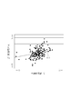
- FIG. 4 is a plot diagram illustrating a correlation between an actually measured bulge value acquired in the flow of FIG. 2 and a predicted bulge value acquired in the flow of FIG. 3. It is the schematic which showed the bulkiness measuring apparatus of the tobacco raw material which concerns on 2nd Embodiment of this invention. It is a flowchart which shows the regression type preparation method performed with the measurement part and calculating part of FIG. It is a flowchart which shows the bulge evaluation method performed with the calculating part of FIG. It is a plot figure which shows the correlation with the actual measurement bulge value acquired by the flow of FIG. 6, and the estimated bulge value acquired by the flow of FIG.
- the bulkiness measuring device 1 is used, for example, in an expansion process of a medium bone 100 as a cigarette raw material, and when the medium bone 100 is conveyed as a layered flow on a conveyance path, The bulkiness of the bone 100 is measured and evaluated online.
- the medium bone 100 is formed by pressing, cutting, and expanding a rod-shaped medium bone separated from leaf tobacco.
- the intermediate bone 100 is expanded by spraying high temperature steam with an intermediate bone expander (not shown), and then the intermediate bone 100 expanded by the fluidized bed dryer 2 is dried with hot air. Let Then, the process which makes the water
- the bulkiness measuring device 1 is provided between the fluidized bed dryer 2 and the silo 4.
- the bulge measuring device 1 includes a conveyor 6, a storage room 7, an actual measurement unit 8, and a calculation unit 10.
- the conveyor 6 forms a part of the conveyance path of the medium bone 100 and includes a conveyance belt 6a and a drive motor 6b.
- the conveyance belt 6a has a conveyance surface having a width Wb, and the medium bone 100 stacked in layers on the conveyance surface is conveyed at a conveyance speed Vt by driving of the drive motor 6b.
- the conveyor 6 is provided with a weigher 12 positioned upstream of the transport path and a sampling unit 14 positioned downstream of the transport path.
- the weigher 12 detects the passing weight W per unit time of the flow of the medium bone 100 that is transported by the transport belt 6 a and passes through the weigher 12.
- the sampling unit 14 includes a diverter (shunt) and a shooter (not shown), and periodically or automatically collects a part of the flow of the medium bone 100 transported on the transport belt 6a as a sample 102.
- the conveyor 6 includes a first layer thickness sensor (first detection unit) 16, a moisture meter (first detection unit) 18, an article between the weigher (first detection unit) 12 and the sampling unit 14.
- first detection unit a first layer thickness sensor
- first detection unit a moisture meter
- second detection unit a thermometer
- second detection unit a thermometer
- the first layer thickness sensor 16 is provided immediately downstream of the weigher 12 and detects the layer thickness T1 of the flow of the medium bone 100 conveyed on the conveyor 6.
- the first layer thickness sensor 16 is, for example, a laser reflection type sensor.
- the moisture meter 18 and the thermometer 20 detect the moisture and temperature of the medium bone 100 conveyed on the conveyor 6 as parameters (first parameters) X2 and X3 relating to the properties of the medium bone 100.
- the parameter X1 related to the density of the medium bone 100 will be described later in detail.
- thermometer 22 and the hygrometer 24 are provided in the vicinity of the conveyor 6, and detect the temperature and humidity around the conveyor 6 as parameters (second parameters) X4 and X5 relating to the installation environment of the bulge measuring device 1, respectively.
- the actual measurement unit 8 is an offline measurement device. The actual measurement unit 8 measures the actual measured bulge value Y1 of the sample 102 after being stored in the storage room 7 for a certain time (for example, 48 hours or more). The sample 102 after the measurement is returned from the actual measurement unit 8 to the conveyor 6 and reused as the medium bone 100.
- the calculation unit 10 includes an expression creation unit 26, a prediction unit 28, and an evaluation unit 30.
- a first layer thickness sensor 16, a moisture meter 18, a thermometer 20, a thermometer 22, a hygrometer 24, a drive motor 6 b, a weigher 12, and an actual measurement unit 8 are electrically connected to the calculation unit 10, Regarding the flow of the bone carving 100, data including the layer thickness T1, the passing weight W, the conveyance speed Vt, the moisture X2, and the temperature X3 and the data including the temperature X4 and the humidity X5 around the bulge measuring device 1 are created. Input to the unit 26.
- the formula creation unit 26 multiplies the width Wb of the transport surface of the conveyor 6 by the layer thickness T1 and the transport speed Vt, and passes the bone directly under the first layer thickness sensor 16.
- the passage volume V per unit time is calculated with respect to the flow at 100 intervals.
- the middle bone 100 in the flow of the middle bone 100 passing directly below the first layer thickness sensor 16 is obtained.
- X1 W / V (3)
- a plurality of (for example, three) first layer thickness sensors 16 may be installed in the width direction of the transport surface of the conveyor 6, and the passing volume V and thus the density X1 may be calculated more strictly using these sensors.
- regression formula creation method With reference to the flowchart of FIG. 2, a regression formula creation flow will be described in the method for measuring the bulkiness of the midbone 100 executed by the calculation unit 10.
- step S1 sampling step
- step S2 sampling step
- step S2 the collected sample 102 is moved to the storage room 7, for example, stored for 48 hours or more, and the process proceeds to step S3.
- step S3 actual measurement step
- the actual measurement bulge value Y1 of the sample 102 after storage is measured by the actual measurement unit 8, and the process proceeds to step S4.
- step S5 data W, T1, Vt, and parameters X2 to X5 are detected at almost the same timing as the sample 102 collection in step S1, and the process proceeds to step S6.
- step S6 the parameter of the density X1 is calculated using the above equations (2) and (3) from the constant data Wb and the detected data W, T1, and Vt, and the process proceeds to step S4.
- step S4 first and second detection steps
- the parameters X1 to X5 and the actually measured bulge value Y1 are all acquired, and the process proceeds to step S7.
- step S7 it is determined whether or not the sampling in steps S1 to S3 has been performed N times (for example, 5 times) together with the detection and calculation in steps S5 and S6.
- N times for example, 5 times
- step S8 the formula creation unit 26 performs multivariate analysis using the N sets of parameters X1 to X5 and the measured bulge value Y1 to determine the coefficient of the regression equation.
- the regression formula F expressed by the following formula (4) for calculating the predicted bulge value Y from the values of X1 to X5 is created, and the regression formula creation flow ends.
- Y ⁇ 0 + ⁇ 1, X1 + ⁇ 2, X2 + ⁇ 3, X3 + ⁇ 4, X4 + ⁇ 5, X5 + ⁇ 6, X6 + ⁇ 7, X7 + ⁇ 8, X8 (4) ⁇ 0 to ⁇ 8 are coefficients.
- step S11 data W, T1, Vt, and parameters X2 to X5 are detected in step S11, and the process proceeds to step S12.
- step S12 the parameter of the density X1 is calculated using the above formulas (2) and (3) from the constant data Wb and the detected data W, T1, and Vt, and the process proceeds to step S13.
- step S13 all parameters X1 to X5 are acquired, and the process proceeds to step S14.
- step S14 prediction step
- the prediction unit 28 calculates the predicted bulge value Y of the intermediate bone 100 by substituting the parameters X1 to X5 into the regression equation F of the above equation (3), and proceeds to step S15. To do.
- step S15 evaluation step
- the evaluation unit 30 compares the predicted bulge value Y with the target bulge value Yt of the intermediate bone notch 100, and determines the bulge of the intermediate bone 100 conveyed on the conveyor 6. evaluate. Specifically, it is determined whether or not the predicted bulge value Y is within a reference range of ⁇ ⁇ of the target bulge value Yt.
- the determination result is true (Yes)
- the process proceeds to step S11, and the bulge evaluation of the midbone 100 of the next cycle is performed.
- the determination result is false (No)
- the process proceeds to step S16.
- step S16 an alarm or the like informs the outside that the bulge value of the intermediate bone 100 is an NG determination outside the reference range, and the bulge evaluation flow ends.
- the driving motor 6b of the conveyor 6 may be stopped, and the conveyance of the medium bone 100 may be stopped.
- the predicted bulge value Y is calculated by periodically substituting the respective parameters X1 to X5 into F, and the predicted bulge value Y is compared with the target bulge value Yt. 100 bulkiness assessments can be performed instantly online.
- ⁇ 0 and ⁇ 1 are coefficients.
- the parameters for obtaining the regression equation F and the predicted bulge value Y include not only the parameters X1 to X3 relating to the properties of the medium bone 100 but also the parameters X4 and X5 relating to the installation environment of the bulge measuring device 1.
- the accuracy of the bulge evaluation of the medium bone 100 can be further enhanced.
- the bulkiness measuring device 32 of the second embodiment is different from the bulkiness measuring device 1 of the first embodiment between the weighing instrument 12 and the sampling unit 14 on the transport path of the conveyor 6.
- a press roller (third detection unit) 34, a second layer thickness sensor (third detection unit) 36, and a third layer thickness sensor (third detection unit) 38 are further added. Since other configurations are the same as those of the first embodiment, the same reference numerals are given and description thereof is omitted.
- the press roller 34 is supported downstream of the first layer thickness sensor 16 so as to be rotatable and vertically movable.
- the press roller 34 rotates at a peripheral speed substantially the same as the conveying speed of the conveying belt 6 a, and rotates in a direction in which the intermediate bone 100 with the conveying belt 6 a is sent downstream of the conveyor 6. Then, when the flow of the medium bone 100 collides with the press roller 34, the flow of the medium bone 100 is compressed with a constant compression force. That is, the first layer thickness sensor 16 is disposed upstream of the press roller 34 and detects the layer thickness of the flow of the medium bone 100 before compression by the press roller 34, that is, the layer thickness T1 before compression.
- the press roller 34 includes a piston 34a that allows the press roller 34 to move up and down so that the flow of the medium bone 100 can be compressed with a constant compressive force even when the pre-compression layer thickness T1 changes.
- the compressive force of the medial embossment 100 by the press roller 34 is defined by the weight of the assembly of the press roller 34 and the pressing force by the piston 34a.
- the second layer thickness sensor 36 is a laser type sensor similar to the first layer thickness sensor 16, and in the case of FIG. 5, it is the same position as the support position of the press roller 34 when viewed in the flow direction of the middle bone 100. It is arranged in.
- the second layer thickness sensor 36 detects the layer thickness of the flow immediately after the flow of the medium bone 100 is compressed by the press roller 34, that is, the layer thickness T2 immediately after compression.
- the layer thickness T2 immediately after compression may be detected based on the height of the press roller 34 corresponding to the operation of the piston 34a.
- the second layer thickness sensor 36 may be disposed immediately downstream of the press roller 34.
- the third layer thickness sensor 38 is a laser type sensor similar to the first and second layer thickness sensors 16 and 36, and is disposed downstream of the second layer thickness sensor 36, and the flow of the medium bone 100 is pressed.
- the layer thickness of the flow after being restored after being compressed by the roller 34, that is, the layer thickness T3 after restoration is detected.
- the compression rate and restoration rate of the flow of the medium bone 100 by the press roller 34 are calculated as parameters (third parameters) X6, X7, and X8 relating to the flexibility of the medium bone 100 conveyed on the conveyor 6.
- the compression layer thickness dT1 of the flow of the medium bone 100 by the press roller 34 is calculated by subtracting the layer thickness T2 immediately after compression from the layer thickness T1 before compression.
- dT1 T1-T2 (6)
- the compression rate of the flow of the medium bone 100 by the press roller 34 is calculated as a parameter X6 by dividing the compression layer thickness dT1 by the pre-compression layer thickness T1.
- X6 dT1 / T1 (7)
- the restoration layer thickness dT2 of the flow of the medium bone 100 by the press roller 34 is calculated by subtracting the layer thickness T2 immediately after compression from the layer thickness T3 after restoration.
- dT2 T3-T2 (8)
- the restoration rate of the flow of the medium bone 100 by the press roller 34 is calculated as a parameter X7 by dividing the restoration layer thickness dT2 by the layer thickness T2 immediately after compression.
- X7 dT2 / T2 (9)
- step S21 sampling step
- step S22 the collected sample 102 is moved to the storage room 7, for example, stored for 48 hours or more, and the process proceeds to step S23.
- step S23 actual measurement step
- the actual measurement unit 8 measures the actual measured bulge value Y1 of the sample 102 after storage, and the process proceeds to step S24.
- step S25 data W, T1, Vt, T2, T3 and parameters X2 to X5, X8 are detected at almost the same timing as the sample 102 collection in step S1, and the process proceeds to step S26.
- step S26 the parameter of the density X1 is calculated using the above equations (2) and (3) based on the constant data Wb and the detected data W, T1, and Vt, and the above equation based on the data T1 and T2.
- the parameters of the compression ratio X6 are calculated using (6) and (7), and the parameters of the restoration ratio X7 are calculated using the above equations (8) and (9) from the data T2 and T3. Transition.
- step S24 (third detection step), the parameters X1 to X8 and the actually measured bulge value Y1 are all acquired, and the process proceeds to step S27.
- step S27 it is determined whether or not the sampling in steps S21 to S23 has been performed N times (for example, 8 times) together with the detection and calculation in steps S25 and S26. When the determination result is false (No), the process proceeds to steps S21 and S25, and sampling is performed again. On the other hand, when the determination result is true (Yes), the process proceeds to step S28.
- step S28 the formula creation unit 26 performs a multivariate analysis using the N sets of parameters X1 to X8 and the measured bulge value Y1, and calculates the predicted bulge value Y from the values of the parameters X1 to X8.
- the regression equation F as expressed by the above equation (3) for calculating the above is created, and the regression equation creation flow ends.
- step S31 data W, T1, Vt, T2, T3, and parameters X2 to X5, X8 are detected in step S31, and the process proceeds to step S32.
- step S32 the parameter of the density X1 is calculated using the above equations (2) and (3) from the constant data Wb and the detected data W, T1, and Vt.
- step S33 all parameters X1 to X8 are acquired, and the process proceeds to step S34.
- step S34 prediction step
- step S35 evaluation step
- step S35 evaluation step
- the evaluation unit 30 compares the predicted bulge value Y with the target bulge value Yt of the midbone increment 100, and determines the bulge nature of the midbone 100 conveyed on the conveyor 6. evaluate.
- step S31 it is determined whether or not the predicted bulge value Y is within a reference range of ⁇ ⁇ of the target bulge value Yt.
- the bulkiness measuring apparatus 1 according to the second embodiment and the bulkiness measuring method using the same are also set in the regression formula F after the regression formula F is created, as in the first embodiment.
- the predicted bulge value Y is calculated by periodically substituting X1 to X8, and the bulge of the intermediate incision 100 conveyed on the conveyor 6 can be obtained by simply comparing the predicted bulge value Y with the target bulge value Yt. Sex assessments can be performed instantly online.
- parameters for obtaining the regression equation F and the predicted bulge value Y include parameters X1 to X3 relating to the properties of the medium bone 100 and parameters relating to the installation environment of the bulge measuring device 1.
- the measured bulge value Y1 is measured after storage in the storage room 7.
- the prediction accuracy of the bulge value by the regression equation F, and hence the accuracy of the bulge evaluation of the middle bone 100 can be further enhanced.
- the present invention is not limited to this, and the measured bulge value Y1 may be measured by the measurement unit 8 immediately after sampling without passing through the storage in the storage room 7.
- the actual measurement unit 8 may measure the actual measured bulge value using a bulk density measuring device other than the D51 type described above. In this case, of course, the storage time required for the sample is secured in accordance with the measurement standard of the apparatus.
- the regression equation F is continuously updated according to the flowchart of FIG. 2 or 6 based on the accumulated sampling data every time sampling is performed. Is preferred.
- the predicted bulge value Y corrected to be closer to the actually measured bulge value Y1 is obtained.
- the bulge measuring device when the first parameters (X1 to X3) relating to the properties of the medium bone 100 are used, in the second embodiment, in addition to the first parameters (X1 to X3), the bulge measuring device
- the second parameter (X4, X5) related to the installation environment 1 in the third embodiment, in addition to the first and second parameters (X1 to X5), the third parameter (X6) related to the property of the midbone 100 is used.
- the case of using X8) has been described.
- the present invention is not limited to this, and an embodiment using the first and third parameters (X1 to X3, X6 to X8) may be used, or an embodiment using the second and third parameters (X6 to X8). It may be.
- the present invention is applicable to the measurement and evaluation of not only the medium bone 100 but also other tobacco materials and mixtures containing a plurality of types of tobacco materials.
Landscapes
- Investigating Or Analysing Materials By Optical Means (AREA)
Abstract
搬送経路(6)上をたばこ原料が層状の流れとして搬送される際、前記たばこ原料(100)の膨嵩性をオンラインで測定して評価する膨嵩性測定装置(1)は、搬送経路を搬送されるたばこ原料の性状に関する第1パラメータを検出する第1検出部(18、20)と、実測膨嵩値と第1パラメータとにより多変量解析を行い、実測膨嵩値を第1パラメータを用いて求める回帰式を作成する式作成部(26)と、回帰式に第1パラメータを代入し、たばこ原料の予測膨嵩値を算出する予測部(28)と、予測部で算出された予測膨嵩値とたばこ原料の目標膨嵩値とを比較し、搬送経路を搬送されるたばこ原料の膨嵩性を評価する評価部(30)とを備える。
Description
本発明は、たばこ原料の膨嵩性測定装置及び膨嵩性測定方法に関する。
特許文献1には、コンベアからなる搬送経路を搬送されるたばこ原料の膨嵩性を測定する膨嵩性測定装置が開示されている。この装置では、たばこ原料の試料が搬送経路からダイバータ(分流器)によって分離されて採取され、この後、採取した試料は圧縮経路を通過する過程で一定の荷重を受けて圧縮され、ここでの圧縮は少なくとも25秒継続される。
そして、圧縮後の試料の層厚及び単位時間当たりの通過重量を測定し、また、コンベアの搬送ベルトの搬送速度及びコンベアの搬送面の幅から、試料の単位時間当たりの通過体積を算出する。更に、これら通過体積及び通過重量から試料の嵩密度ひいては膨嵩値が算出される。この実測膨嵩値は、測定した試料の水分及び品温により補正された後、その膨嵩性の良否が評価される。
上記特許文献1の装置では、ダイバータによってサンプリングした試料は本来の搬送経路から圧縮経路に移送され、この圧縮経路を圧縮されながら通過する。この場合、試料の膨嵩値が目標膨嵩値の範囲を外れて基準外であると、たばこ原料の搬送装置が停止されるが、ここでの停止までには試料の検査に要求される圧縮時間だけのタイムラグが生じる。これでは、サンプリングした試料を含むロットのたばこ原料は、既に次工程に移送されているため、たばこ原料の膨嵩性が基準外となる不良品が多量に発生するおそれがある。
ところで、たばこ原料の1つである中骨刻の膨化工程では、例えば、中骨膨化機にて高温蒸気を噴霧して中骨刻を膨化させた後、流動層乾燥機にて膨化した中骨刻を熱風で乾燥させる。この後、上記膨化工程を経た中骨刻の膨嵩性を搬送経路から抽出して膨嵩性測定装置で測定する際には、恒温恒湿の蔵置室にて中骨刻を一定時間(例えば48時間以上)蔵置して水分及び品温を落ち着かせる処理が行われる。
しかし、サンプリングから48時間以上の蔵置を経た試料の膨嵩値を測定することとなるため、蔵置後の試料の膨嵩値が基準外であったとき、搬送経路を流れる中骨刻に極めて多量の不良品が発生するおそれがある。このため、たばこ原料の膨嵩性評価をオンラインで行い且つ膨嵩性の傾向をリアルタイムで検出することが従来より求められていた。
本発明はこのような課題に鑑みてなされたものであり、その目的とするところは、たばこ原料の膨嵩性評価をオンラインで行い且つ膨嵩性の傾向をリアルタイムで検出することができる、たばこ原料の膨嵩性測定装置及び膨嵩性測定方法を提供することにある。
上記目的を達成するため、本発明のたばこ原料の膨嵩性測定装置は、搬送経路上をたばこ原料が層状の流れとして搬送される際、たばこ原料の膨嵩性をオンラインで測定して評価する膨嵩性測定装置であって、搬送経路からたばこ原料の試料を採取するためのサンプリング部と、試料の実測膨嵩値を測定する実測部と、搬送経路を搬送されるたばこ原料の性状に関する第1パラメータを検出する第1検出部と、実測膨嵩値と第1パラメータとにより多変量解析を行い、実測膨嵩値を第1パラメータを用いて求める回帰式を作成する式作成部と、回帰式に第1パラメータを代入し、たばこ原料の予測膨嵩値を算出する予測部と、予測部で算出された予測膨嵩値とたばこ原料の目標膨嵩値とを比較し、搬送経路を搬送されるたばこ原料の膨嵩性を評価する評価部とを備える。
また、本発明のたばこ原料の膨嵩性測定方法は、搬送経路上をたばこ原料が層状の流れとして搬送される際、たばこ原料の膨嵩性をオンラインで測定して評価する膨嵩性測定方法であって、搬送経路からたばこ原料の試料を採取するサンプリングステップと、試料の実測膨嵩値を測定する実測ステップと、搬送経路を搬送されるたばこ原料の性状に関する第1パラメータを検出する第1検出ステップと、実測膨嵩値と第1パラメータとにより多変量解析を行い、実測膨嵩値を第1パラメータを用いて求める回帰式を作成する式作成ステップと、回帰式に第1パラメータを代入し、たばこ原料の予測膨嵩値を算出する予測ステップと、予測部で算出された予測膨嵩値とたばこ原料の目標膨嵩値とを比較し、搬送経路を搬送されるたばこ原料の膨嵩性を評価する評価ステップとを含む。
本発明のたばこ原料の膨嵩性測定装置及び膨嵩性測定方法によれば、たばこ原料の膨嵩性評価をオンラインで行い且つ膨嵩性の傾向をリアルタイムで検出することができる。
以下、図面に基づき本発明の実施形態に係るたばこ原料の膨嵩性測定装置について説明する。
<第1実施形態>
図1に示すように、膨嵩性測定装置1は、例えばたばこ原料としての中骨刻100の膨化工程で使用され、搬送経路上を中骨刻100が層状の流れとして搬送される際、中骨刻100の膨嵩性をオンラインで測定して評価する。中骨刻100とは、葉たばこから分離された棒状の中骨を圧展、裁刻、膨化して形成される。
<第1実施形態>
図1に示すように、膨嵩性測定装置1は、例えばたばこ原料としての中骨刻100の膨化工程で使用され、搬送経路上を中骨刻100が層状の流れとして搬送される際、中骨刻100の膨嵩性をオンラインで測定して評価する。中骨刻100とは、葉たばこから分離された棒状の中骨を圧展、裁刻、膨化して形成される。
中骨刻100の膨化工程では、図示しない中骨膨化機にて高温蒸気を噴霧して中骨刻100を膨化させた後、流動層乾燥機2にて膨化した中骨刻100を熱風で乾燥させる。この後、恒温恒湿のサイロ4にて中骨刻100を一定時間蔵置して水分及び品温を落ち着かせる処理が行われている。膨嵩性測定装置1は、流動層乾燥機2とサイロ4との間に設けられている。
膨嵩性測定装置1は、コンベア6、蔵置室7、実測部8、及び演算部10を備えている。コンベア6は中骨刻100の搬送経路の一部を形成し、搬送ベルト6aと駆動モータ6bとを有する。搬送ベルト6aは幅Wbの搬送面を有し、この搬送面に層状に積層された中骨刻100は、駆動モータ6bの駆動により搬送速度Vtで搬送される。
また、コンベア6には、搬送経路の上流に位置する計重器12と、搬送経路の下流に位置するサンプリング部14とが設けられている。
また、コンベア6には、搬送経路の上流に位置する計重器12と、搬送経路の下流に位置するサンプリング部14とが設けられている。
計重機12は、搬送ベルト6aにより搬送されて計重器12を通過する中骨刻100の流れの単位時間当たりの通過重量Wを検出する。
サンプリング部14は、図示しないダイバータ(分流器)やシュータから構成され、搬送ベルト6aを搬送される中骨刻100の流れの一部を試料102として周期的に自動又は手動で採取する。
サンプリング部14は、図示しないダイバータ(分流器)やシュータから構成され、搬送ベルト6aを搬送される中骨刻100の流れの一部を試料102として周期的に自動又は手動で採取する。
また、コンベア6には、計重器(第1検出部)12とサンプリング部14との間に、第1層厚センサ(第1検出部)16、水分計(第1検出部)18、品温計(第1検出部)20、気温計(第2検出部)22、及び湿度計(第2検出部)24が更に設けられている。
第1層厚センサ16は、計重機12の下流直近に設けられ、コンベア6上を搬送される中骨刻100の流れの層厚T1を検出する。第1層厚センサ16は例えばレーザ反射式センサである。また、水分計18、品温計20は、コンベア6上を搬送される中骨刻100の水分、温度を中骨刻100の性状に関するパラメータ(第1パラメータ)X2、X3として検出する。なお、中骨刻100の密度に関するパラメータX1に関しては後で詳述する。
また、気温計22及び湿度計24は、コンベア6の近傍に設けられ、それぞれコンベア6の周囲の気温、湿度を膨嵩性測定装置1の設置環境に関するパラメータ(第2パラメータ)X4、X5として検出する。
一方、実測部8はオフラインの測定機器である。実測部8では蔵置室7にて一定時間(例えば48時間以上)蔵置された後の試料102の実測膨嵩値Y1を測定する。測定後の試料102は実測部8からコンベア6に戻され、中骨刻100として再利用される。
一方、実測部8はオフラインの測定機器である。実測部8では蔵置室7にて一定時間(例えば48時間以上)蔵置された後の試料102の実測膨嵩値Y1を測定する。測定後の試料102は実測部8からコンベア6に戻され、中骨刻100として再利用される。
(試料の実測膨嵩値の測定方法)
実測部8は、ドイツ国のボルグワルド社(Borgwaldt GmbH)製 Factory Densimeter D51型の嵩密度測定器を用い、以下のように実測膨嵩値を測定する。
1)直径95mm(底面積A)のシリンダに70g(W1)の試料を充填する。
2)11.4kgの荷重が付与されたピストンで試料を5秒間圧縮する。
3)圧縮された試料の層厚Tを測定する。
4)試料を一定圧力で圧縮したときの単位重量当たりの体積(cm3/100g)、即ち、膨嵩値FP以下の式(1)により算出する。
FP=(A×T)/W1×100・・・(1)
実測部8は、ドイツ国のボルグワルド社(Borgwaldt GmbH)製 Factory Densimeter D51型の嵩密度測定器を用い、以下のように実測膨嵩値を測定する。
1)直径95mm(底面積A)のシリンダに70g(W1)の試料を充填する。
2)11.4kgの荷重が付与されたピストンで試料を5秒間圧縮する。
3)圧縮された試料の層厚Tを測定する。
4)試料を一定圧力で圧縮したときの単位重量当たりの体積(cm3/100g)、即ち、膨嵩値FP以下の式(1)により算出する。
FP=(A×T)/W1×100・・・(1)
また、演算部10は、式作成部26、予測部28、評価部30を備えている。演算部10には、第1層厚センサ16、水分計18、品温計20、気温計22、湿度計24、駆動モータ6b、計重器12、実測部8が電気的に接続され、中骨刻100の流れに関して、層厚T1、通過重量W、搬送速度Vt、水分X2、温度X3を含むデータと、膨嵩性測定装置1の周囲の気温X4、湿度X5を含むデータとが式作成部26に入力される。
(中骨刻の密度算出方法)
式作成部26では、以下の式(2)に示すように、コンベア6の搬送面の幅Wbに層厚T1及び搬送速度Vtを乗じて、第1層厚センサ16の直下を通過する中骨刻100の流れに関し、単位時間当たりの通過体積Vを算出する。
V=Wb×T1×Vt・・・(2)
式作成部26では、以下の式(2)に示すように、コンベア6の搬送面の幅Wbに層厚T1及び搬送速度Vtを乗じて、第1層厚センサ16の直下を通過する中骨刻100の流れに関し、単位時間当たりの通過体積Vを算出する。
V=Wb×T1×Vt・・・(2)
次に、以下の式(3)に示すように、通過体積Vで通過重量Wを除することにより、第1層厚センサ16の直下を通過する中骨刻100の流れ中の中骨刻100の密度を前記流れの性状に関するパラメータ(第1パラメータ)X1として算出する。
X1=W/V・・・(3)
なお、第1層厚センサ16をコンベア6の搬送面の幅方向に複数(例えば3つ)設置し、これらセンサを用いて通過体積Vひいては密度X1をより厳密に算出しても良い。
X1=W/V・・・(3)
なお、第1層厚センサ16をコンベア6の搬送面の幅方向に複数(例えば3つ)設置し、これらセンサを用いて通過体積Vひいては密度X1をより厳密に算出しても良い。
(回帰式作成方法)
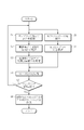
図2のフローチャートを参照して、演算部10で実行される中骨刻100の膨嵩性測定方法のうち、回帰式作成フローについて説明する。
この回帰式作成フローが開始されると、ステップS1(サンプリングステップ)では、サンプリング部14が試料102を採取し、ステップS2に移行する。
図2のフローチャートを参照して、演算部10で実行される中骨刻100の膨嵩性測定方法のうち、回帰式作成フローについて説明する。
この回帰式作成フローが開始されると、ステップS1(サンプリングステップ)では、サンプリング部14が試料102を採取し、ステップS2に移行する。
ステップS2では、採取した試料102を蔵置室7に移動して、例えば48時間以上蔵置し、ステップS3に移行する。
ステップS3(実測ステップ)では、実測部8にて蔵置後の試料102の実測膨嵩値Y1を測定し、ステップS4に移行する。
ステップS3(実測ステップ)では、実測部8にて蔵置後の試料102の実測膨嵩値Y1を測定し、ステップS4に移行する。
一方、ステップS5では、ステップS1の試料102採取とほぼ同じタイミングで、データW、T1、Vt、パラメータX2~X5を検出し、ステップS6に移行する。
ステップS6では、定数となるデータWbと、検出したデータW、T1、Vtとにより上記式(2)、(3)を用いて密度X1のパラメータを算出し、ステップS4に移行する。
ステップS4(第1及び第2検出ステップ)では、パラメータX1~X5、及び実測膨嵩値Y1をすべて取得し、ステップS7に移行する。
ステップS6では、定数となるデータWbと、検出したデータW、T1、Vtとにより上記式(2)、(3)を用いて密度X1のパラメータを算出し、ステップS4に移行する。
ステップS4(第1及び第2検出ステップ)では、パラメータX1~X5、及び実測膨嵩値Y1をすべて取得し、ステップS7に移行する。
ステップS7では、ステップS1~S3のサンプリングがステップS5、S6の検出及び算出とともにN回(例えば5回)実施されたか否かを判定する。判定結果が偽(No)であるときは、ステップS1及びS5に移行し、再びサンプリングを行う。一方、判定結果が真(Yes)であるときは、ステップS8に移行する。
ステップS8(式作成ステップ)では、式作成部26にて、N組の各パラメータX1~X5、実測膨嵩値Y1により多変量解析を行って回帰式の係数を決定し、この結果、各パラメータX1~X5の値から予測膨嵩値Yを算出するための以下の式(4)で表された回帰式Fを作成し、回帰式作成フローは終了する。
Y=β0+β1・X1+β2・X2+β3・X3+β4・X4+β5・X5+β6・X6+β7・X7+β8・X8・・・(4)
なお、β0~β8は係数である。
Y=β0+β1・X1+β2・X2+β3・X3+β4・X4+β5・X5+β6・X6+β7・X7+β8・X8・・・(4)
なお、β0~β8は係数である。
(膨嵩性評価方法)
次に、図3のフローチャートを参照して、演算部10で実行される中骨刻100の膨嵩性測定方法のうち、回帰式Fの作成後に実行される膨嵩性評価フローについて説明する。
この膨嵩性評価フローが開始されると、ステップS11では、データW、T1、Vt、パラメータX2~X5を検出し、ステップS12に移行する。
ステップS12では、定数となるデータWbと、検出したデータW、T1、Vtとにより上記式(2)、(3)を用いて密度X1のパラメータを算出し、ステップS13に移行する。
次に、図3のフローチャートを参照して、演算部10で実行される中骨刻100の膨嵩性測定方法のうち、回帰式Fの作成後に実行される膨嵩性評価フローについて説明する。
この膨嵩性評価フローが開始されると、ステップS11では、データW、T1、Vt、パラメータX2~X5を検出し、ステップS12に移行する。
ステップS12では、定数となるデータWbと、検出したデータW、T1、Vtとにより上記式(2)、(3)を用いて密度X1のパラメータを算出し、ステップS13に移行する。
ステップS13では、パラメータX1~X5をすべて取得し、ステップS14に移行する。
ステップS14(予測ステップ)では、予測部28にて、上記式(3)の回帰式FにパラメータX1~X5を代入して中骨刻100の予測膨嵩値Yを算出し、ステップS15に移行する。
ステップS14(予測ステップ)では、予測部28にて、上記式(3)の回帰式FにパラメータX1~X5を代入して中骨刻100の予測膨嵩値Yを算出し、ステップS15に移行する。
ステップS15(評価ステップ)では、評価部30にて、予測膨嵩値Yと中骨刻み100の目標膨嵩値Ytとを比較し、コンベア6を搬送される中骨刻100の膨嵩性を評価する。具体的には、予測膨嵩値Yが目標膨嵩値Ytの±αの基準範囲内であるか否かを判定する。判定結果が真(Yes)であるときは、ステップS11に移行し、次の周期の中骨刻100の膨嵩性評価を行う。一方、判定結果が偽(No)であるときは、ステップS16に移行する。
ステップS16では、中骨刻100の膨嵩値が基準範囲外のNG判定であることをアラーム等で外部に報知し、膨嵩性評価フローは終了する。なお、膨嵩値NG判定後は、コンベア6の駆動モータ6bを停止し、中骨刻100の搬送を停止する等の処置を行っても良い。
以上のように第1実施形態の膨嵩性測定装置1及びそれを用いた膨嵩性測定方法によれば、図2に示した回帰式作成フローにより回帰式Fを作成した後は、回帰式Fに各パラメータX1~X5を周期的に代入して予測膨嵩値Yを算出し、この予測膨嵩値Yを目標膨嵩値Ytと比較するだけで、コンベア6を搬送される中骨刻100の膨嵩性評価をオンラインで瞬時に行うことができる。
図4に示すように、実測膨嵩値Y1と予測膨嵩値Yとの関係を調査するために、試料102のサンプリングを多数行い、複数回のサンプリング毎に回帰式Fを更新した。この結果、実測膨嵩値Y1と予測膨嵩値Yとの相関は、以下の式(5)に示すような一次の近似式Fnで得られることが判明した。
Y=γ0+γ1×Y1・・・(5)
Y=γ0+γ1×Y1・・・(5)
なお、γ0、γ1は係数である。本評価方法により、コンベア6を搬送される中骨刻100の膨嵩性が目標膨嵩値Ytから大きく逸脱していないことを常時監視可能である。したがって、中骨刻100の膨嵩性評価をオンラインで行い且つ膨嵩性の傾向をリアルタイムで検出することができる。
ここで、夏場と冬場とを比較すると、中骨刻100の膨嵩性に顕著な差が存在するとことが確認されている。
ここで、夏場と冬場とを比較すると、中骨刻100の膨嵩性に顕著な差が存在するとことが確認されている。
したがって、特に、回帰式F及び予測膨嵩値Yを得るためのパラメータに、中骨刻100の性状に関するパラメータX1~X3のみならず、膨嵩性測定装置1の設置環境に関するパラメータX4、X5をも用いることにより、中骨刻100の膨嵩性評価の精度をより一層高めることができる。
<第2実施形態>
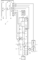
図5に示すように、第2実施形態の膨嵩性測定装置32は、第1実施形態の膨嵩性測定装置1に、コンベア6の搬送経路の計重器12とサンプリング部14との間に、更にプレスローラ(第3検出部)34、第2層厚センサ(第3検出部)36、第3層厚センサ(第3検出部)38を追加した構成を有している。その他の構成は第1実施形態と同様であるため、同符号を付して説明を省略する。
図5に示すように、第2実施形態の膨嵩性測定装置32は、第1実施形態の膨嵩性測定装置1に、コンベア6の搬送経路の計重器12とサンプリング部14との間に、更にプレスローラ(第3検出部)34、第2層厚センサ(第3検出部)36、第3層厚センサ(第3検出部)38を追加した構成を有している。その他の構成は第1実施形態と同様であるため、同符号を付して説明を省略する。
プレスローラ34は、第1層厚センサ16の下流に回転可能に且つ上下移動可能に支持されている。プレスローラ34は、搬送ベルト6aの搬送速度とほぼ同一の周速で回転し、搬送ベルト6aとの間の中骨刻100をコンベア6の下流に送り出す方向に回転する。そして、プレスローラ34に中骨刻100の流れが衝突することにより中骨刻100の流れが一定の圧縮力で圧縮される。即ち、第1層厚センサ16は、プレスローラ34の上流に配され、プレスローラ34による圧縮前の中骨刻100の流れの層厚,即ち、圧縮前層厚T1を検出する。
プレスローラ34は、圧縮前層厚T1が変化しても一定の圧縮力で中骨刻100の流れが圧縮可能なように、プレスローラ34の上下移動を許容するピストン34aを備えている。プレスローラ34による中骨刻100の圧縮力は、プレスローラ34の組立体の自重とピストン34aによる押圧力とにより規定され、ピストン34aによる押圧力を調整することにより、上記一定の圧縮力を中骨刻100の流れに付与することができる。
第2層厚センサ36は、第1層厚センサ16と同様のレーザ式センサであって、図5の場合には、中骨刻100の流れ方向で見てプレスローラ34の支持位置と同位置に配されている。第2層厚センサ36は、中骨刻100の流れがプレスローラ34により圧縮された直後の流れの層厚、即ち、圧縮直後層厚T2を検出する。なお、圧縮直後層厚T2は、ピストン34aの作動に応じたプレスローラ34の高さに基づいて検出しても良い。また、第2層厚センサ36をプレスローラ34の下流直近に配しても良い。
第3層厚センサ38は、第1及び第2層厚センサ16、36と同様のレーザ式センサであって、第2層厚センサ36よりも下流に配され、中骨刻100の流れがプレスローラ34により圧縮された後に復元した後の流れの層厚、即ち、復元後層厚T3を検出する。
第3層厚センサ38は、第1及び第2層厚センサ16、36と同様のレーザ式センサであって、第2層厚センサ36よりも下流に配され、中骨刻100の流れがプレスローラ34により圧縮された後に復元した後の流れの層厚、即ち、復元後層厚T3を検出する。
そして、本実施形態では、第1~第3層厚センサ16、36、38により検出された層厚T1~T3を用いて、それぞれプレスローラ34による中骨刻100の流れの圧縮率、復元率、及び圧縮力をコンベア6上を搬送される中骨刻100の柔軟性に関するパラメータ(第3パラメータ)X6、X7、X8として算出する。
(中骨刻の柔軟性の測定方法)
以下の式(6)に示すように、圧縮前層厚T1から圧縮直後層厚T2を減じることにより、プレスローラ34による中骨刻100の流れの圧縮層厚dT1を算出する。
dT1=T1-T2・・・(6)
そして、以下の式(7)に示すように、圧縮層厚dT1を圧縮前層厚T1で除することによりプレスローラ34による中骨刻100の流れの圧縮率をパラメータX6として算出する。
X6=dT1/T1・・・(7)
以下の式(6)に示すように、圧縮前層厚T1から圧縮直後層厚T2を減じることにより、プレスローラ34による中骨刻100の流れの圧縮層厚dT1を算出する。
dT1=T1-T2・・・(6)
そして、以下の式(7)に示すように、圧縮層厚dT1を圧縮前層厚T1で除することによりプレスローラ34による中骨刻100の流れの圧縮率をパラメータX6として算出する。
X6=dT1/T1・・・(7)
また、以下の式(8)に示すように、復元後層厚T3から圧縮直後層厚T2を減じることによりプレスローラ34による中骨刻100の流れの復元層厚dT2を算出する。
dT2=T3-T2・・・(8)
そして、以下の式(9)に示すように、復元層厚dT2を圧縮直後層厚T2で除することによりプレスローラ34による中骨刻100の流れの復元率をパラメータX7として算出する。
X7=dT2/T2・・・(9)
dT2=T3-T2・・・(8)
そして、以下の式(9)に示すように、復元層厚dT2を圧縮直後層厚T2で除することによりプレスローラ34による中骨刻100の流れの復元率をパラメータX7として算出する。
X7=dT2/T2・・・(9)
また、圧縮前層厚T1が変化してもプレスローラ34から中骨刻100の流れに付与される一定の圧縮力を、以下の式(10)に示すように、プレスローラ34による中骨刻100の圧縮力FのパラメータX8として検出する。
X8=F・・・(10)
なお、圧縮力Fを式(2)で算出された通過体積Vで除した単位体積当たりの値をパラメータX8として使用しても良い。この場合には、通過体積Vは圧縮前層厚T1から算出されるため、圧縮力X8のパラメータは第1層厚センサ16で検出されたデータT1に基づいて決定される。また、この場合には、圧縮力Fの中骨刻100の流れに付与される通過荷重としての値の精度が高まる。
X8=F・・・(10)
なお、圧縮力Fを式(2)で算出された通過体積Vで除した単位体積当たりの値をパラメータX8として使用しても良い。この場合には、通過体積Vは圧縮前層厚T1から算出されるため、圧縮力X8のパラメータは第1層厚センサ16で検出されたデータT1に基づいて決定される。また、この場合には、圧縮力Fの中骨刻100の流れに付与される通過荷重としての値の精度が高まる。
(回帰式作成方法)
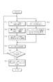
図6のフローチャートを参照して、本実施形態の回帰式作成フローについて説明する。
回帰式作成フローが開始されると、ステップS21(サンプリングステップ)では、サンプリング部14が試料102を採取し、ステップS22に移行する。
ステップS22では、採取した試料102を蔵置室7に移動し、例えば48時間以上蔵置し、ステップS23に移行する。
図6のフローチャートを参照して、本実施形態の回帰式作成フローについて説明する。
回帰式作成フローが開始されると、ステップS21(サンプリングステップ)では、サンプリング部14が試料102を採取し、ステップS22に移行する。
ステップS22では、採取した試料102を蔵置室7に移動し、例えば48時間以上蔵置し、ステップS23に移行する。
ステップS23(実測ステップ)では、実測部8にて蔵置後の試料102の実測膨嵩値Y1を測定し、ステップS24に移行する。
一方、ステップS25では、ステップS1の試料102採取とほぼ同じタイミングで、データW、T1、Vt、T2、T3、パラメータX2~X5、X8を検出し、ステップS26に移行する。
一方、ステップS25では、ステップS1の試料102採取とほぼ同じタイミングで、データW、T1、Vt、T2、T3、パラメータX2~X5、X8を検出し、ステップS26に移行する。
ステップS26では、定数となるデータWbと、検出したデータW、T1、Vtとにより上記式(2)、(3)を用いて密度X1のパラメータを算出し、また、データT1、T2により上記式(6)、(7)を用いて圧縮率X6のパラメータを算出し、また、データT2、T3により上記式(8)、(9)を用いて復元率X7のパラメータを算出し、ステップS24に移行する。
ステップS24(第3検出ステップ)では、パラメータX1~X8、及び実測膨嵩値Y1をすべて取得し、ステップS27に移行する。
ステップS27では、ステップS21~S23のサンプリングがステップS25、S26の検出及び算出とともにN回(例えば8回)実施されたか否かを判定する。判定結果が偽(No)であるときは、ステップS21及びS25に移行し、再びサンプリングを行う。一方、判定結果が真(Yes)であるときは、ステップS28に移行する。
ステップS27では、ステップS21~S23のサンプリングがステップS25、S26の検出及び算出とともにN回(例えば8回)実施されたか否かを判定する。判定結果が偽(No)であるときは、ステップS21及びS25に移行し、再びサンプリングを行う。一方、判定結果が真(Yes)であるときは、ステップS28に移行する。
ステップS28(式作成ステップ)では、式作成部26にて、N組の各パラメータX1~X8、実測膨嵩値Y1により多変量解析を行い、各パラメータX1~X8の値から予測膨嵩値Yを算出するための上記式(3)で表されるような回帰式Fを作成し、回帰式作成フローは終了する。
(膨嵩性評価方法)
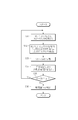
図7のフローチャートを参照して、本実施形態の膨嵩性評価フローについて説明する。
膨嵩性評価フローが開始されると、ステップS31では、データW、T1、Vt、T2、T3、パラメータX2~X5、X8を検出し、ステップS32に移行する。
ステップS32では、定数となるデータWbと、検出したデータW、T1、Vtとにより上記式(2)、(3)を用いて密度X1のパラメータを算出する。
図7のフローチャートを参照して、本実施形態の膨嵩性評価フローについて説明する。
膨嵩性評価フローが開始されると、ステップS31では、データW、T1、Vt、T2、T3、パラメータX2~X5、X8を検出し、ステップS32に移行する。
ステップS32では、定数となるデータWbと、検出したデータW、T1、Vtとにより上記式(2)、(3)を用いて密度X1のパラメータを算出する。
また、データT1、T2により上記式(6)、(7)を用いて圧縮率X6のパラメータを算出し、また、データT2、T3により上記式(8)、(9)を用いて復元率X7のパラメータを算出し、ステップS33に移行する。
ステップS33では、パラメータX1~X8をすべて取得し、ステップS34に移行する。
ステップS33では、パラメータX1~X8をすべて取得し、ステップS34に移行する。
ステップS34(予測ステップ)では、予測部28にて、上記回帰式FにパラメータX1~X8を代入して中骨刻100の予測膨嵩値Yを算出し、ステップS35に移行する。
ステップS35(評価ステップ)では、評価部30にて、予測膨嵩値Yと中骨刻み100の目標膨嵩値Ytとを比較し、コンベア6を搬送される中骨刻100の膨嵩性を評価する。
ステップS35(評価ステップ)では、評価部30にて、予測膨嵩値Yと中骨刻み100の目標膨嵩値Ytとを比較し、コンベア6を搬送される中骨刻100の膨嵩性を評価する。
具体的には、予測膨嵩値Yが目標膨嵩値Ytの±αの基準範囲内であるか否かを判定する。判定結果が真(Yes)であるときは、ステップS31に移行し、次の周期の中骨刻100の膨嵩性評価を行う。一方、判定結果が偽(No)であるときは、ステップS36に移行する。
ステップS36では、中骨刻100の膨嵩値が基準範囲外のNG判定であることをアラーム等で外部に報知し、膨嵩性評価フローは終了し、コンベア6の駆動モータ6bを停止する処置等が行われる。
ステップS36では、中骨刻100の膨嵩値が基準範囲外のNG判定であることをアラーム等で外部に報知し、膨嵩性評価フローは終了し、コンベア6の駆動モータ6bを停止する処置等が行われる。
以上のように第2実施形態の膨嵩性測定装置1及びそれを用いた膨嵩性測定方法も、第1実施形態の場合と同様に、回帰式Fを作成後は回帰式Fに各パラメータX1~X8を周期的に代入して予測膨嵩値Yを算出し、この予測膨嵩値Yを目標膨嵩値Ytと比較するだけで、コンベア6を搬送される中骨刻100の膨嵩性評価をオンラインで瞬時に行うことができる。
また、図8に示すように、実測膨嵩値Y1と予測膨嵩値Yとの関係を調査するために、試料102のサンプリングを多数行い、複数回のサンプリング毎に回帰式Fを更新した。この結果、実測膨嵩値Y1と予測膨嵩値Yとの相関は、以下の式(11)に示すような一次の近似式Fn1で得られることが判明した。
Y=δ0+δ1×Y1・・・(11)
Y=δ0+δ1×Y1・・・(11)
なお、δ0、δ1(>γ1)は係数である。本評価方法により、第1実施形態の場合と同様に、コンベア6上を搬送される中骨刻100の膨嵩性が目標膨嵩値Ytから大きく逸脱していないことを常時監視可能である。
特に、本実施形態の場合には、回帰式F及び予測膨嵩値Yを得るためのパラメータに、中骨刻100の性状に関するパラメータX1~X3と、膨嵩性測定装置1の設置環境に関するパラメータX4、X5とのみならず、中骨刻100の柔軟性に関するパラメータX6~X8をも用いることにより、中骨刻100の膨嵩性評価の精度をより一層高めることができる。
特に、本実施形態の場合には、回帰式F及び予測膨嵩値Yを得るためのパラメータに、中骨刻100の性状に関するパラメータX1~X3と、膨嵩性測定装置1の設置環境に関するパラメータX4、X5とのみならず、中骨刻100の柔軟性に関するパラメータX6~X8をも用いることにより、中骨刻100の膨嵩性評価の精度をより一層高めることができる。
このことは、式(11)の近似式Fn1の傾きδ1が第1実施形態の場合の近似式Fnの傾きγ1よりも大きくなり、第1実施形態の場合に比して予測膨嵩値Yが実測膨嵩値Y1に近づいていることからも明らかである。
以上で本発明の各実施形態についての説明を終えるが、本発明はこれに限定されるものではなく、本発明の趣旨を逸脱しない範囲で種々の変更ができるものである。
以上で本発明の各実施形態についての説明を終えるが、本発明はこれに限定されるものではなく、本発明の趣旨を逸脱しない範囲で種々の変更ができるものである。
例えば、上記各実施形態では、実測膨嵩値Y1を蔵置室7での蔵置後に測定している。これにより、回帰式Fによる膨嵩値の予測精度、ひいては中骨刻100の膨嵩性評価の精度をより一層高めることができる。しかし、これに限らず、実測膨嵩値Y1を蔵置室7における蔵置を経ないでサンプリング直後に実測部8で測定しても良い。なお、実測部8では、上述したD51型以外の嵩密度測定器を用いて実測膨嵩値を測定しても良い。この場合には、当該装置の測定基準に則って、試料に要求される蔵置時間を確保することは勿論である。
また、サンプリング回数Nが多いほど回帰式Fの精度は高まるため、定期的にサンプリングを行う度に、蓄積されたサンプリングデータに基づいて図2又は図6のフローチャートにより回帰式Fを更新し続けるのが好ましい。
また、上記各実施形態で得られた上記近似式Fn、Fn1に予測膨嵩値Yを代入することにより、より実測膨嵩値Y1に近づくように補正された予測膨嵩値Yを取得し、この補正された予測膨嵩値Yで中骨刻100の膨嵩性を評価するステップを実行しても良い。これにより、中骨刻100の膨嵩性評価の精度をより一層高めることができる。
また、第1実施形態では、中骨刻100の性状に関する第1パラメータ(X1~X3)を使用する場合、第2実施形態では、第1パラメータ(X1~X3)に加え、膨嵩性測定装置1の設置環境に関する第2パラメータ(X4、X5)を使用する場合、第3実施形態では、第1及び第2パラメータ(X1~X5)に加え、中骨刻100の性状に関する第3パラメータ(X6~X8)を使用する場合について説明した。しかし、これらに限らず、第1及び第3パラメータ(X1~X3、X6~X8)を使用する実施形態であっても良いし、第2及び第3パラメータ(X6~X8)を使用する実施形態であっても良い。
また、本発明は、中骨刻100に限らず他のたばこ原料、また、複数種のたばこ原料を含む混合物の膨嵩性測定、評価にも適用可能であることは勿論である。
1 膨嵩性測定装置
6 コンベア(搬送経路)
8 実測部
14 サンプリング部
12 計重器(第1検出部)
16 第1層厚センサ(第1検出部)
18 水分計(第1検出部)
20 品温計(第1検出部)
22 気温計(第2検出部)
24 湿度計(第2検出部)
26 式作成部
28 予測部
30 評価部
32 膨嵩性測定装置
34 プレスローラ(第3検出部)
36 第2層厚センサ(第3検出部)
38 第3層厚センサ(第3検出部)
100 中骨刻(たばこ原料)
102 試料
6 コンベア(搬送経路)
8 実測部
14 サンプリング部
12 計重器(第1検出部)
16 第1層厚センサ(第1検出部)
18 水分計(第1検出部)
20 品温計(第1検出部)
22 気温計(第2検出部)
24 湿度計(第2検出部)
26 式作成部
28 予測部
30 評価部
32 膨嵩性測定装置
34 プレスローラ(第3検出部)
36 第2層厚センサ(第3検出部)
38 第3層厚センサ(第3検出部)
100 中骨刻(たばこ原料)
102 試料
Claims (14)
- 搬送経路上をたばこ原料が層状の流れとして搬送される際、前記たばこ原料の膨嵩性をオンラインで測定して評価する膨嵩性測定装置であって、
前記搬送経路から前記たばこ原料の試料を採取するためのサンプリング部と、
前記試料の実測膨嵩値を測定する実測部と、
前記搬送経路を搬送される前記たばこ原料の性状に関する第1パラメータを検出する第1検出部と、
前記実測膨嵩値と前記第1パラメータとにより多変量解析を行い、前記実測膨嵩値を前記第1パラメータを用いて求める回帰式を作成する式作成部と、
前記回帰式に前記第1パラメータを代入し、前記たばこ原料の予測膨嵩値を算出する予測部と、
前記予測部で算出された前記予測膨嵩値と前記たばこ原料の目標膨嵩値とを比較し、前記搬送経路を搬送される前記たばこ原料の膨嵩性を評価する評価部と
を備える、たばこ原料の膨嵩性測定装置。 - 前記第1パラメータは、前記たばこ原料の密度、水分、及び温度を含む、請求項1に記載のたばこ原料の膨嵩性測定装置。
- 前記膨嵩性測定装置の設置環境に関する第2パラメータを検出する第2検出部を更に備え、
前記式作成部は、前記実測膨嵩値と前記第1及び第2パラメータとにより多変量解析を行い、前記実測膨嵩値を前記第1及び第2パラメータを用いて求める回帰式を作成し、
前記予測部は、前記回帰式に前記第1及び第2パラメータを代入し、前記たばこ原料の予測膨嵩値を算出する、請求項1又は2に記載のたばこ原料の膨嵩性測定装置。 - 前記第2パラメータは、前記膨嵩性測定装置の周囲の気温及び湿度を含む、請求項3に記載のたばこ原料の膨嵩性測定装置。
- 前記搬送経路を搬送される前記たばこ原料の柔軟性に関する第3パラメータを検出する第3検出部を更に備え、
前記式作成部は、前記実測膨嵩値と前記第1から第3パラメータとにより多変量解析を行い、前記実測膨嵩値を前記第1から第3パラメータを用いて求める回帰式を作成し、
前記予測部は、前記回帰式に前記第1から第3パラメータを代入し、前記たばこ原料の予測膨嵩値を算出する、請求項3又は4に記載のたばこ原料の膨嵩性測定装置。 - 前記第3検出部は、
前記搬送経路上の前記たばこ原料の流れを所定の圧縮力で圧縮するプレスローラと、
前記プレスローラの上流に配され、前記プレスローラによる圧縮前の前記流れの圧縮前層厚を検出する第1層厚センサと、
前記プレスローラの直下又は下流直近に配され、前記プレスローラによる圧縮直後の前記流れの圧縮直後層厚を検出する第2層厚センサと、
前記第2層厚センサよりも下流に配され、前記たばこ原料の流れが復元した後の前記流れの復元後層厚を検出する第3層厚センサと
を含む、請求項5に記載のたばこ原料の膨嵩性測定装置。 - 前記第3パラメータは、前記圧縮前層厚、前記圧縮直後層厚、及び前記復元後層厚の何れかにより算出された前記たばこ原料の圧縮率及び復元率と、前記圧縮力とを含む、請求項6に記載のたばこ原料の膨嵩性測定装置。
- 搬送経路上をたばこ原料が層状の流れとして搬送される際、前記たばこ原料の膨嵩性をオンラインで測定して評価する膨嵩性測定方法であって、
前記搬送経路から前記たばこ原料の試料を採取するサンプリングステップと、
前記試料の実測膨嵩値を測定する実測ステップと、
前記搬送経路を搬送される前記たばこ原料の性状に関する第1パラメータを検出する第1検出ステップと、
前記実測膨嵩値と前記第1パラメータとにより多変量解析を行い、前記実測膨嵩値を前記第1パラメータを用いて求める回帰式を作成する式作成ステップと、
前記回帰式に前記第1パラメータを代入し、前記たばこ原料の予測膨嵩値を算出する予測ステップと、
前記予測ステップで算出された前記予測膨嵩値と前記たばこ原料の目標膨嵩値とを比較し、前記搬送経路を搬送される前記たばこ原料の膨嵩性を評価する評価ステップと
を含む、たばこ原料の膨嵩性測定方法。 - 前記第1パラメータは、前記たばこ原料の密度、水分、及び温度を含む、請求項8に記載のたばこ原料の膨嵩性測定方法。
- 前記膨嵩性測定方法が実行される環境に関する第2パラメータを検出する第2検出ステップを更に含み、
前記式作成ステップでは、前記実測膨嵩値と前記第1及び第2パラメータとにより多変量解析を行い、前記実測膨嵩値を前記第1及び第2パラメータを用いて求める回帰式を作成し、
前記予測ステップでは、前記回帰式に前記第1及び第2パラメータを代入し、前記たばこ原料の予測膨嵩値を算出する、請求項8又は9に記載のたばこ原料の膨嵩性測定方法。 - 前記第2パラメータは、前記膨嵩性測定方法が実行される場所の周囲の気温及び湿度を含む、請求項10に記載のたばこ原料の膨嵩性測定方法。
- 前記搬送経路を搬送される前記たばこ原料の柔軟性に関する第3パラメータを検出する第3検出ステップを更に含み、
前記式作成ステップでは、前記実測膨嵩値と前記第1から第3パラメータとにより多変量解析を行い、前記実測膨嵩値を前記第1から第3パラメータを用いて求める回帰式を作成し、
前記予測ステップでは、前記回帰式に前記第1から第3パラメータを代入し、前記たばこ原料の予測膨嵩値を算出する、請求項10又は11に記載のたばこ原料の膨嵩性測定方法。 - 前記第3検出ステップでは、前記搬送経路上の前記たばこ原料の流れを所定の圧縮力で圧縮し、前記たばこ原料の圧縮前の前記流れの圧縮前層厚、前記たばこ原料の圧縮直後の前記流れの圧縮直後層厚、及び前記たばこ原料の流れが復元した後の前記流れの復元後層厚を検出する、請求項12に記載のたばこ原料の膨嵩性測定方法。
- 前記第3パラメータは、前記圧縮前層厚、前記圧縮直後層厚、及び前記復元後層厚の何れかにより算出された前記たばこ原料の圧縮率及び復元率と、前記圧縮力とを含む、請求項13に記載のたばこ原料の膨嵩性測定方法。
Priority Applications (1)
| Application Number | Priority Date | Filing Date | Title |
|---|---|---|---|
| PCT/JP2015/060147 WO2016157414A1 (ja) | 2015-03-31 | 2015-03-31 | たばこ原料の膨嵩性測定装置及び膨嵩性測定方法 |
Applications Claiming Priority (1)
| Application Number | Priority Date | Filing Date | Title |
|---|---|---|---|
| PCT/JP2015/060147 WO2016157414A1 (ja) | 2015-03-31 | 2015-03-31 | たばこ原料の膨嵩性測定装置及び膨嵩性測定方法 |
Publications (1)
| Publication Number | Publication Date |
|---|---|
| WO2016157414A1 true WO2016157414A1 (ja) | 2016-10-06 |
Family
ID=57004008
Family Applications (1)
| Application Number | Title | Priority Date | Filing Date |
|---|---|---|---|
| PCT/JP2015/060147 Ceased WO2016157414A1 (ja) | 2015-03-31 | 2015-03-31 | たばこ原料の膨嵩性測定装置及び膨嵩性測定方法 |
Country Status (1)
| Country | Link |
|---|---|
| WO (1) | WO2016157414A1 (ja) |
Cited By (1)
| Publication number | Priority date | Publication date | Assignee | Title |
|---|---|---|---|---|
| WO2019004003A1 (ja) * | 2017-06-28 | 2019-01-03 | 日本たばこ産業株式会社 | 葉たばこ中骨の膨こう性の推定方法 |
Citations (2)
| Publication number | Priority date | Publication date | Assignee | Title |
|---|---|---|---|---|
| JPS5982075A (ja) * | 1982-06-02 | 1984-05-11 | エイエムエフ・インコ−ポレ−テツド | カツトされたタバコのような嵩密度材料の連続測定装置 |
| US6463794B1 (en) * | 2000-04-10 | 2002-10-15 | Malcam Ltd. | Method and device for non-invasively determining moisture content and uniformity of solid plant matter during on-line drying or cooling forced-air treatment |
-
2015
- 2015-03-31 WO PCT/JP2015/060147 patent/WO2016157414A1/ja not_active Ceased
Patent Citations (2)
| Publication number | Priority date | Publication date | Assignee | Title |
|---|---|---|---|---|
| JPS5982075A (ja) * | 1982-06-02 | 1984-05-11 | エイエムエフ・インコ−ポレ−テツド | カツトされたタバコのような嵩密度材料の連続測定装置 |
| US6463794B1 (en) * | 2000-04-10 | 2002-10-15 | Malcam Ltd. | Method and device for non-invasively determining moisture content and uniformity of solid plant matter during on-line drying or cooling forced-air treatment |
Cited By (1)
| Publication number | Priority date | Publication date | Assignee | Title |
|---|---|---|---|---|
| WO2019004003A1 (ja) * | 2017-06-28 | 2019-01-03 | 日本たばこ産業株式会社 | 葉たばこ中骨の膨こう性の推定方法 |
Similar Documents
| Publication | Publication Date | Title |
|---|---|---|
| US9863917B2 (en) | Method and system for real-time vibroacoustic condition monitoring and fault diagnostics in solid dosage compaction presses | |
| RU2016133591A (ru) | Аппарат для тестирования картона | |
| Bawuah et al. | Non-contact weight measurement of flat-faced pharmaceutical tablets using terahertz transmission pulse delay measurements | |
| CN114760969B (zh) | 质量测量方法和质量测量装置 | |
| US9457353B2 (en) | Coal pulverizer monitoring system and associated methods | |
| EP1978359A1 (en) | Methods for predicting warp at a given condition | |
| WO2016157414A1 (ja) | たばこ原料の膨嵩性測定装置及び膨嵩性測定方法 | |
| CN108291881B (zh) | 用于确定添加剂份额的设备和方法以及烟草加工业的机器 | |
| CN113597367A (zh) | 用于监测用于运送挤压物料的加载有润滑剂的环绕运行的带的润滑状态的设备 | |
| KR101775777B1 (ko) | 철강 플랜트의 경향 감시 장치 | |
| CN111108372A (zh) | 固相分数传感器用于评估目标药物样品的固相分数的用途和固相分数传感器 | |
| US20080170236A1 (en) | Method and apparatus for measuring expansion of materials | |
| CN117597574A (zh) | 用于实时确定改性过程中吸湿材料的属性的方法和装置 | |
| JP2022522856A (ja) | 検査ステーションおよびシート材料を検査するための方法 | |
| Lewis et al. | Field testing a microwave moisture sensor for real-time kernel moisture content monitoring during peanut drying | |
| KR101377802B1 (ko) | 유압 설비의 성능 변화 모니터링 장치 | |
| Baiano et al. | Analysis of cracking and breakage in dried pasta: a case study | |
| CA3268247A1 (en) | METHOD AND SYSTEM FOR MEASURING THE SETTING TIME OF A PLASTER BOARD | |
| Perré et al. | The existence of a first drying stage for potato proved by two independent methods | |
| EP4490500A1 (en) | Method and apparatus for characterising a material using planar electrical capacitance tomography | |
| JP3917073B2 (ja) | シート状食品の厚さの検出方法、判別方法、及びシート状食品の製造方法、並びにこれらの装置 | |
| Ünsal et al. | Optimizing lumber drying schedules For Oriental beech and sessile oak using acoustic emission | |
| US20220196574A1 (en) | Method and device for determining the material moisture of a material | |
| JPWO2002016869A1 (ja) | シート状食品の厚さの検出方法、判別方法、及びシート状食品の製造方法、並びにこれらの装置 | |
| Voicu et al. | Considerations about the sheeting of dough pieces to obtain bread. |
Legal Events
| Date | Code | Title | Description |
|---|---|---|---|
| 121 | Ep: the epo has been informed by wipo that ep was designated in this application |
Ref document number: 15887567 Country of ref document: EP Kind code of ref document: A1 |
|
| NENP | Non-entry into the national phase |
Ref country code: DE |
|
| 122 | Ep: pct application non-entry in european phase |
Ref document number: 15887567 Country of ref document: EP Kind code of ref document: A1 |
|
| NENP | Non-entry into the national phase |
Ref country code: JP |