WO2016155133A1 - 天线匹配电路的控制方法、控制装置和终端 - Google Patents
天线匹配电路的控制方法、控制装置和终端 Download PDFInfo
- Publication number
- WO2016155133A1 WO2016155133A1 PCT/CN2015/082931 CN2015082931W WO2016155133A1 WO 2016155133 A1 WO2016155133 A1 WO 2016155133A1 CN 2015082931 W CN2015082931 W CN 2015082931W WO 2016155133 A1 WO2016155133 A1 WO 2016155133A1
- Authority
- WO
- WIPO (PCT)
- Prior art keywords
- antenna
- matching circuit
- terminal
- state
- antenna matching
- Prior art date
- Legal status (The legal status is an assumption and is not a legal conclusion. Google has not performed a legal analysis and makes no representation as to the accuracy of the status listed.)
- Ceased
Links
Images



Classifications
-
- H—ELECTRICITY
- H01—ELECTRIC ELEMENTS
- H01Q—ANTENNAS, i.e. RADIO AERIALS
- H01Q5/00—Arrangements for simultaneous operation of antennas on two or more different wavebands, e.g. dual-band or multi-band arrangements
- H01Q5/50—Feeding or matching arrangements for broad-band or multi-band operation
Definitions
- the present invention relates to the field of terminal technologies, and in particular, to a method for controlling an antenna matching circuit, a control device for an antenna matching circuit, and a terminal.
- the ability to flexibly adjust the antenna pattern will give the user a better experience in many cases.
- the user always wants the GPS antenna pattern to point as far as possible in different situations. That is, the direction of the satellite, and when making a call, the user always wants the antenna pattern of the base station communication antenna (such as GSM, CDMA, WCDMA, LTE, etc.) to point to the direction of the base station as much as possible, thereby obtaining a high signal to noise ratio.
- the base station communication antenna such as GSM, CDMA, WCDMA, LTE, etc.
- the current method of adjusting the antenna pattern through the antenna array is not applicable to the mobile terminal.
- the present invention is based on the above problems, and proposes a new technical solution, which enables the terminal to freely adjust the antenna pattern when the placement state and/or the service quality change, so that the antenna pattern always points to the base station or the satellite. Thereby the radiation direction is flexibly adjusted, so that the terminal always maintains a high signal to noise ratio.
- an aspect of the present invention provides a method for controlling an antenna matching circuit, including: when an insertion state and/or a service quality of a terminal changes, an antenna matching circuit currently used by an antenna of the terminal is configured by The current antenna matching circuit is switched to the target antenna matching circuit to adjust the antenna pattern of the terminal; after adjusting the antenna pattern of the terminal, acquiring the current signal quality and/or the current signal strength of the terminal; Whether the current signal quality and/or the current signal strength is increased, and when the determination result is yes, controlling the antenna to continue using the target antenna matching circuit; otherwise, controlling the antenna to reuse the current antenna matching circuit.
- the antenna currently used by the antenna of the terminal may be used.
- the matching circuit is switched from the current antenna matching circuit to the target antenna matching circuit, thereby adjusting the antenna pattern of the antenna, and after adjusting the antenna pattern, determining whether the current signal quality of the terminal and/or the current signal strength is improved, if it is improved , indicating that the signal-to-noise ratio of the terminal is improved, further indicating that the adjustment pattern is more effective, and the antenna pattern is further directed to the base station or the satellite, and the antenna should be controlled to continue to use the switched target antenna matching circuit; otherwise, the description After adjusting the antenna pattern, the adjusted antenna pattern is further deviated from the base station or satellite, and the signal-to-noise ratio of the terminal is also reduced.
- the antenna should be controlled to reuse the current antenna matching circuit before switching, thereby realizing
- the terminal can freely adjust when the placement status and/or quality of service changes.
- Antenna pattern the antenna pattern is always toward the base station or satellite so that the flexibility to adjust the direction of the radiation, so that the terminal always maintain a high signal to noise ratio.
- the adjusted antenna pattern points to a device having a base station function of a serving cell where the terminal is located or a satellite providing a service service for the terminal.
- the antenna points to the device or satellite with the function of the base station; of course, the antenna pattern points to the device with the function of the base station or to the satellite, depending on the type of the antenna, and the device with the function of the base station includes the base station and the communication device (such as A micro cell base station or the like implemented by a smartphone or the like).
- the antenna is provided with a detachable antenna grounding switch, and the antenna grounding switch is disposed at a lower end of the metal structural member between the symmetric breakpoints of the metal middle frame of the terminal, and
- the antenna matching circuit currently used by the antenna of the terminal is switched from the current antenna matching circuit to the target antenna matching circuit, and specifically includes: switching the conduction state to the off state or disconnecting by controlling the antenna grounding switch The state is switched to an on state to control the antenna matching circuit to be switched by the current antenna matching circuit to the target antenna matching circuit.
- the antenna grounding switch can be controlled when the terminal placement state and/or the service quality changes.
- the conduction state changes, and the environment around the antenna such as the impedance can be controlled to change, thereby controlling the local current distribution of the antenna to change, thereby accurately controlling the antenna matching circuit to be switched from the current antenna matching circuit to the target antenna matching circuit, and the specific
- the switching process is: if the antenna is used in the current antenna matching circuit, the antenna grounding switch is in an on state, and when the antenna matching circuit of the antenna is switched to the target antenna matching circuit, the antenna grounding switch is in an off state; or if the antenna uses the current antenna When the circuit is matched, the antenna grounding switch is in the off state.
- the antenna grounding switch is turned on, which can be freely set according to the actual situation.
- the method further includes: when the antenna grounding switch is switched from an on state to an off state, the metal structural member is changed from a ground state to a floating state; and the antenna grounding switch is When the disconnection state is switched to the on state, the metal structural member changes from a suspended state to a grounded state.
- the antenna grounding switch is disposed at the lower end of the metal structural member between the symmetric breakpoints of the metal middle frame, if the antenna grounding switch is switched from the conductive state to the open state, the metal structural member is grounded. The state becomes a floating state, and when the antenna grounding switch is switched from the off state to the on state, the metal structural member naturally changes from the suspended state to the grounded state, thereby realizing that the antenna matching circuit of the antenna is switched from the current antenna matching circuit to the target. Antenna matching circuit.
- the current antenna matching circuit and the target antenna matching circuit are disposed in an antenna tuning module of the terminal, and the antenna tuning module includes two single-pole double-throw switches, and Two single pole double throw switches are used for the antenna grounding switch according to the antenna The on/off state selects the current antenna matching circuit or the target antenna matching circuit.
- the current antenna matching circuit or the target antenna matching circuit when selecting the current antenna matching circuit or the target antenna matching circuit, including but not limited to using two single-pole double-throw switches in the antenna tuning module, the current antenna matching circuit or target is selected according to the on-off state of the antenna grounding switch.
- the antenna matching circuit can be any means that allows the antenna to freely switch the antenna matching circuit according to changes in the placement state and/or quality of service.
- Another aspect of the present invention provides a control device for an antenna matching circuit, comprising: a switching unit, when an antenna of the terminal is currently used, an antenna matching circuit is used when a placement state and/or a service quality of the terminal is changed.
- the current antenna matching circuit is switched to the target antenna matching circuit to adjust the antenna pattern of the terminal; and the acquiring unit obtains the current signal quality and/or the current signal strength of the terminal after adjusting the antenna pattern of the terminal; a determining unit, determining whether the current signal quality and/or the current signal strength is improved; and the control unit, when the determination result is yes, controlling the antenna to continue to use the target antenna matching circuit; otherwise, controlling the antenna
- the current antenna matching circuit is reused.
- the antenna currently used by the antenna of the terminal may be used.
- the matching circuit is switched from the current antenna matching circuit to the target antenna matching circuit, thereby adjusting the antenna pattern of the antenna, and after adjusting the antenna pattern, determining whether the current signal quality of the terminal and/or the current signal strength is improved, if it is improved , indicating that the signal-to-noise ratio of the terminal is improved, further indicating that the adjustment pattern is more effective, and the antenna pattern is further directed to the base station or the satellite, and the antenna should be controlled to continue to use the switched target antenna matching circuit; otherwise, the description After adjusting the antenna pattern, the adjusted antenna pattern is further deviated from the base station or satellite, and the signal-to-noise ratio of the terminal is also reduced.
- the antenna should be controlled to reuse the current antenna matching circuit before switching, thereby realizing
- the terminal can freely adjust when the placement status and/or quality of service changes.
- Antenna pattern the antenna pattern is always toward the base station or satellite so that the flexibility to adjust the direction of the radiation, so that the terminal always maintain a high signal to noise ratio.
- the pointing unit when the determination result is yes, the adjusted antenna pattern points to a device with a base station function of the serving cell where the terminal is located or provides a service service for the terminal. Satellite.
- the antenna pattern is adjusted, the current signal quality of the terminal and/or The current signal strength is improved, indicating that the signal-to-noise ratio of the terminal is improved, further indicating that the adjustment pattern is more effective, and the antenna pattern is directed to a device or satellite having a base station function; of course, the antenna pattern is pointed to
- the base station function device is also directed to the satellite, depending on the type of the antenna, and the device having the base station function includes a base station, a micro cell base station implemented by a communication device (such as a smart phone, etc.).
- the antenna is provided with a detachable antenna grounding switch, and the antenna grounding switch is disposed at a lower end of the metal structural member between the symmetric breakpoints of the metal middle frame of the terminal, and
- the switching unit is specifically configured to: control the antenna matching circuit to be switched by the current antenna matching circuit by controlling the antenna grounding switch to switch from an on state to an off state or from an off state to an on state.
- the target antenna matching circuit is specifically configured to: control the antenna matching circuit to be switched by the current antenna matching circuit by controlling the antenna grounding switch to switch from an on state to an off state or from an off state to an on state.
- the antenna grounding switch can be controlled when the terminal placement state and/or the service quality changes.
- the conduction state changes, and the environment around the antenna such as the impedance can be controlled to change, thereby controlling the local current distribution of the antenna to change, thereby accurately controlling the antenna matching circuit to be switched from the current antenna matching circuit to the target antenna matching circuit, and the specific
- the switching process is: if the antenna is used in the current antenna matching circuit, the antenna grounding switch is in an on state, and when the antenna matching circuit of the antenna is switched to the target antenna matching circuit, the antenna grounding switch is in an off state; or if the antenna uses the current antenna When the circuit is matched, the antenna grounding switch is in the off state.
- the antenna grounding switch is turned on, which can be freely set according to the actual situation.
- the method further includes: when the antenna grounding switch is switched from an on state to an off state, the metal structural member is changed from a ground state to a floating state; and the antenna grounding switch is When the disconnection state is switched to the on state, the metal structural member changes from a suspended state to a grounded state.
- the antenna grounding switch is disposed at the lower end of the metal structural member between the symmetric breakpoints of the metal middle frame, if the antenna grounding switch is switched from the conductive state to the open state, the metal structural member is grounded. The state becomes a floating state, and when the antenna grounding switch is switched from the off state to the on state, the metal structural member naturally changes from the suspended state to the grounded state, thereby realizing that the antenna matching circuit of the antenna is switched from the current antenna matching circuit to the target. Antenna matching circuit.
- the current antenna matching circuit and the target antenna matching circuit are disposed in an antenna tuning module of the terminal, and the antenna tuning module includes two single-pole double-throw switches, and The two single-pole double-throw switches are used to select the current antenna matching circuit or the target antenna matching circuit according to the on-off state of the antenna grounding switch.
- the current antenna matching circuit or the target antenna matching circuit when selecting the current antenna matching circuit or the target antenna matching circuit, including but not limited to using two single-pole double-throw switches in the antenna tuning module, the current antenna matching circuit or target is selected according to the on-off state of the antenna grounding switch.
- the antenna matching circuit can be any means that allows the antenna to freely switch the antenna matching circuit according to changes in the placement state and/or quality of service.
- Yet another aspect of the present invention provides a terminal, including a processor, a memory, and an antenna, wherein the memory stores a set of program codes, and the processor is configured to call program code stored in the memory for Do the following:
- the antenna matching circuit currently used by the antenna of the terminal is switched from the current antenna matching circuit to the target antenna matching circuit to adjust the antenna pattern of the terminal; After adjusting an antenna pattern of the terminal, acquiring a current signal quality and/or a current signal strength of the terminal; determining whether the current signal quality and/or the current signal strength is improved, and when the determination result is yes, Controlling the antenna to continue to use the target antenna matching circuit; otherwise, controlling the antenna to reuse the current antenna matching circuit.
- the adjusted antenna pattern points to a device having a base station function of a serving cell where the terminal is located or a satellite providing a service service for the terminal.
- the antenna is provided with a detachable antenna grounding switch, and the antenna grounding switch is disposed at a lower end of the metal structural member between the symmetric breakpoints of the metal middle frame of the terminal, and
- the processor switches the antenna matching circuit currently used by the antenna of the terminal from the current antenna matching circuit to the target antenna matching circuit, and specifically includes:
- the antenna matching circuit is controlled to be switched by the current antenna matching circuit to the target antenna matching circuit by controlling the antenna grounding switch to be switched from an on state to an off state or from an off state to an on state.
- the antenna grounding switch is switched from an on state to In the off state, the metal structural member changes from a grounded state to a suspended state; and when the antenna grounding switch is switched from an off state to an on state, the metal structural member changes from a suspended state to a grounded state.
- the current antenna matching circuit and the target antenna matching circuit are disposed in an antenna tuning module of the terminal, and the antenna tuning module includes two single-pole double-throw switches, and The two single-pole double-throw switches are used to select the current antenna matching circuit or the target antenna matching circuit according to the on-off state of the antenna grounding switch.
- the terminal can freely adjust the antenna pattern when the placement state and/or the service quality change, so that the antenna pattern always points to the base station or the satellite, thereby flexibly adjusting the radiation direction, so that the terminal always Maintain a high signal to noise ratio.
- FIG. 1 is a flow chart showing a control method of an antenna matching circuit according to an embodiment of the present invention
- FIG. 2 is a block diagram showing the structure of a control device for an antenna matching circuit according to an embodiment of the present invention
- FIG. 3 is a schematic structural diagram of a terminal according to an embodiment of the present invention.
- FIG. 4 is a block diagram showing the structure of an antenna system of a terminal according to an embodiment of the present invention.
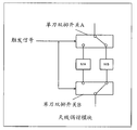
- FIG. 5 is a circuit diagram showing the antenna tuning module of Figure 4.
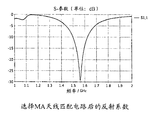
- FIG. 6 is a schematic diagram showing a reflection coefficient between a terminal and a satellite and/or a base station after the antenna tuning module of FIG. 5 selects an MA antenna matching circuit;
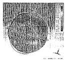
- FIG. 7 is a schematic diagram showing an antenna pattern used by an antenna after the antenna tuning module of FIG. 5 selects an MA antenna matching circuit
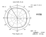
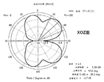
- Figure 8 shows a screenshot of the XOZ plane of the antenna pattern of Figure 7;
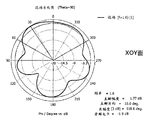
- Figure 9 shows a screenshot of the XOY face of the antenna pattern of Figure 7;
- FIG. 10 is a schematic diagram showing a reflection coefficient between a terminal and a satellite and/or a base station after the antenna tuning module of FIG. 5 selects an MB antenna matching circuit;
- Figure 11 shows the antenna tuning module of Figure 5 after the selection of the MB antenna matching circuit. Schematic diagram of the antenna pattern used;
- Figure 12 shows a screenshot of the XOZ plane of the antenna pattern of Figure 11;
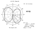
- Figure 13 shows a screenshot of the XOY plane of the antenna pattern of Figure 11;
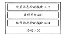
- FIG. 14 is a block diagram showing the structure of a terminal according to another embodiment of the present invention.
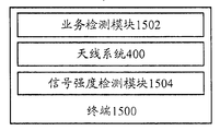
- FIG. 15 is a block diagram showing the structure of a terminal according to still another embodiment of the present invention.
- Figure 16 is a diagram showing simulation results of an antenna pattern according to an embodiment of the present invention.
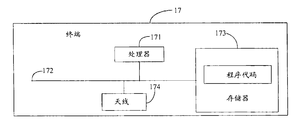
- FIG. 17 is a block diagram showing the structure of a terminal according to another embodiment of the present invention.
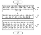
- FIG. 1 is a flow chart showing a control method of an antenna matching circuit according to an embodiment of the present invention.
- a method for controlling an antenna matching circuit includes: Step 102: When the placement state and/or service quality of the terminal changes, the antenna of the terminal is currently used. The antenna matching circuit used is switched from the current antenna matching circuit to the target antenna matching circuit to adjust the antenna pattern of the terminal.
- step 104 after adjusting the antenna pattern of the terminal, the current signal quality of the terminal is obtained. / or current signal strength; step 106, determining whether the current signal quality and / or the current signal strength is improved, and when the determination result is yes, controlling the antenna to continue using the target antenna matching circuit; otherwise, controlling The antenna reuses the current antenna matching circuit.
- the antenna currently used by the antenna of the terminal may be used.
- the matching circuit is switched from the current antenna matching circuit to the target antenna matching circuit, thereby adjusting the antenna pattern of the antenna, and after adjusting the antenna pattern, judging the terminal Whether the current signal quality and/or the current signal strength is improved, if it is improved, the signal-to-noise ratio of the terminal is improved, further indicating that the adjustment pattern is more effective, and the antenna pattern is further pointed to the base station or the satellite.
- the antenna should be controlled to continue to use the switched target antenna matching circuit; otherwise, the adjusted antenna pattern is further deviated from the base station or satellite after the antenna pattern is adjusted, and the signal-to-noise ratio of the terminal is also reduced. Controlling the antenna to reuse the current antenna matching circuit before switching, thereby realizing that the terminal can freely adjust the antenna pattern when the placement state and/or the service quality changes, so that the antenna pattern always points to the base station or the satellite, thereby being flexible Adjust the radiation direction to ensure that the terminal always maintains a high signal-to-noise ratio.
- the adjusted antenna pattern points to a device having a base station function of a serving cell where the terminal is located or a satellite providing a service service for the terminal.
- the antenna points to the device or satellite with the function of the base station; of course, the antenna pattern points to the device with the function of the base station or to the satellite, depending on the type of the antenna, and the device with the function of the base station includes the base station and the communication device (such as A micro cell base station or the like implemented by a smartphone or the like).
- the antenna is provided with a detachable antenna grounding switch, and the antenna grounding switch is disposed at a lower end of the metal structural member between the symmetric breakpoints of the metal middle frame of the terminal, and
- the antenna matching circuit currently used by the antenna of the terminal is switched from the current antenna matching circuit to the target antenna matching circuit, and specifically includes: switching the conduction state to the off state or disconnecting by controlling the antenna grounding switch The state is switched to an on state to control the antenna matching circuit to be switched by the current antenna matching circuit to the target antenna matching circuit.
- the antenna grounding switch can be controlled when the terminal placement state and/or the service quality changes.
- the conduction state changes, and the environment around the antenna such as the impedance can be controlled to change, thereby controlling the local current distribution of the antenna to change, thereby accurately controlling the antenna matching circuit to be switched from the current antenna matching circuit to the target antenna matching circuit, and
- the specific switching process is: if the antenna uses the current antenna matching circuit, the antenna grounding switch is in an on state, and when the antenna matching circuit of the antenna is switched to the target antenna matching circuit, the antenna grounding switch is in an off state; or if the antenna is used In the current antenna matching circuit, when the antenna grounding switch is in the off state, when the antenna matching circuit of the antenna is switched to the target antenna matching circuit, the antenna grounding switch is in an on state, which can be freely set according to actual conditions.
- the method further includes: when the antenna grounding switch is switched from an on state to an off state, the metal structural member is changed from a ground state to a floating state; and the antenna grounding switch is When the disconnection state is switched to the on state, the metal structural member changes from a suspended state to a grounded state.
- the antenna grounding switch is disposed at the lower end of the metal structural member between the symmetric breakpoints of the metal middle frame, if the antenna grounding switch is switched from the conductive state to the open state, the metal structural member is grounded. The state becomes a floating state, and when the antenna grounding switch is switched from the off state to the on state, the metal structural member naturally changes from the suspended state to the grounded state, thereby realizing that the antenna matching circuit of the antenna is switched from the current antenna matching circuit to the target. Antenna matching circuit.
- the current antenna matching circuit and the target antenna matching circuit are disposed in an antenna tuning module of the terminal, and the antenna tuning module includes two single-pole double-throw switches, and The two single-pole double-throw switches are used to select the current antenna matching circuit or the target antenna matching circuit according to the on-off state of the antenna grounding switch.
- the current antenna matching circuit or the target antenna matching circuit when selecting the current antenna matching circuit or the target antenna matching circuit, including but not limited to using two single-pole double-throw switches in the antenna tuning module, the current antenna matching circuit or target is selected according to the on-off state of the antenna grounding switch.
- the antenna matching circuit can be any means that allows the antenna to freely switch the antenna matching circuit according to changes in the placement state and/or quality of service.
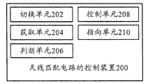
- FIG. 2 is a block diagram showing the structure of a control device for an antenna matching circuit according to an embodiment of the present invention.
- a control device 200 for an antenna matching circuit includes: a switching unit 202, when the placement state and/or quality of service of the terminal changes, the antenna of the terminal is The current antenna matching circuit is switched from the current antenna matching circuit to the target antenna matching circuit to adjust the antenna pattern of the terminal.
- the obtaining unit 204 obtains the current state of the terminal after adjusting the antenna pattern of the terminal. Signal quality and / or current signal
- the determining unit 206 determines whether the current signal quality and/or the current signal strength is improved; the control unit 208 controls the antenna to continue to use the target antenna matching circuit when the determination result is YES; otherwise, Controlling the antenna to reuse the current antenna matching circuit.
- the antenna currently used by the antenna of the terminal may be used.
- the matching circuit is switched from the current antenna matching circuit to the target antenna matching circuit, thereby adjusting the antenna pattern of the antenna, and after adjusting the antenna pattern, determining whether the current signal quality of the terminal and/or the current signal strength is improved, if it is improved , indicating that the signal-to-noise ratio of the terminal is improved, further indicating that the adjustment pattern is more effective, and the antenna pattern is further directed to the base station or the satellite, and the antenna should be controlled to continue to use the switched target antenna matching circuit; otherwise, the description After adjusting the antenna pattern, the adjusted antenna pattern is further deviated from the base station or satellite, and the signal-to-noise ratio of the terminal is also reduced.
- the antenna should be controlled to reuse the current antenna matching circuit before switching, thereby realizing
- the terminal can freely adjust when the placement status and/or quality of service changes.
- Antenna pattern the antenna pattern is always toward the base station or satellite so that the flexibility to adjust the direction of the radiation, so that the terminal always maintain a high signal to noise ratio.
- the pointing unit 210 when the determination result is yes, the adjusted antenna pattern points to a device with a base station function of the serving cell where the terminal is located or provides a service for the terminal. Serving satellites.
- the antenna points to the device or satellite with the function of the base station; of course, the antenna pattern points to the device with the function of the base station or to the satellite, depending on the type of the antenna, and the device with the function of the base station includes the base station and the communication device (such as A micro cell base station or the like implemented by a smartphone or the like).
- the antenna is provided with a detachable antenna grounding switch, and the antenna grounding switch is disposed at a lower end of the metal structural member between the symmetric breakpoints of the metal middle frame of the terminal, and
- the switching unit 202 is specifically configured to: control the antenna matching circuit to be switched by the current antenna matching circuit by controlling the antenna grounding switch to be switched from an on state to an off state or from an off state to an on state. Matching the circuit for the target antenna.
- the antenna grounding switch can be controlled when the terminal placement state and/or the service quality changes.
- the conduction state changes, and the environment around the antenna such as the impedance can be controlled to change, thereby controlling the local current distribution of the antenna to change, thereby accurately controlling the antenna matching circuit to be switched from the current antenna matching circuit to the target antenna matching circuit, and the specific
- the switching process is: if the antenna is used in the current antenna matching circuit, the antenna grounding switch is in an on state, and when the antenna matching circuit of the antenna is switched to the target antenna matching circuit, the antenna grounding switch is in an off state; or if the antenna uses the current antenna When the circuit is matched, the antenna grounding switch is in the off state.
- the antenna grounding switch is turned on, which can be freely set according to the actual situation.
- the method further includes: when the antenna grounding switch is switched from an on state to an off state, the metal structural member is changed from a ground state to a floating state; and the antenna grounding switch is When the disconnection state is switched to the on state, the metal structural member changes from a suspended state to a grounded state.
- the antenna grounding switch is disposed at the lower end of the metal structural member between the symmetric breakpoints of the metal middle frame, if the antenna grounding switch is switched from the conductive state to the open state, the metal structural member is grounded. The state becomes a floating state, and when the antenna grounding switch is switched from the off state to the on state, the metal structural member naturally changes from the suspended state to the grounded state, thereby realizing that the antenna matching circuit of the antenna is switched from the current antenna matching circuit to the target. Antenna matching circuit.
- the current antenna matching circuit and the target antenna matching circuit are disposed in an antenna tuning module of the terminal, and the antenna tuning module includes two single-pole double-throw switches, and The two single-pole double-throw switches are used to select the current antenna matching circuit or the target antenna matching circuit according to the on-off state of the antenna grounding switch.
- the current antenna matching circuit or the target antenna matching circuit when selecting the current antenna matching circuit or the target antenna matching circuit, including but not limited to using two single-pole double-throw switches in the antenna tuning module, the current antenna matching circuit or target is selected according to the on-off state of the antenna grounding switch.
- the antenna matching circuit can be any means that allows the antenna to freely switch the antenna matching circuit according to changes in the placement state and/or quality of service.
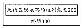
- FIG. 3 shows a schematic structural diagram of a terminal according to an embodiment of the present invention.
- a terminal 300 includes: The control device 200 of the antenna matching circuit according to any one of the aspects.
- the terminal 300 can be freely adjusted when the placement state and/or the service quality changes, so that the antenna pattern always points.
- Base stations or satellites which flexibly adjust the radiation direction so that the terminal always maintains a high signal-to-noise ratio.
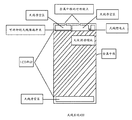
- FIG. 4 is a schematic structural view of an antenna system of a terminal according to an embodiment of the present invention
- FIG. 5 is a circuit diagram of the antenna tuning module of FIG. 4
- FIG. 6 is a diagram showing the antenna tuning module of FIG. Schematic diagram of the reflection coefficient between the terminal and the satellite and/or the base station after selecting the MA antenna matching circuit
- FIG. 7 is a screenshot showing the antenna pattern used by the antenna after the antenna tuning module of FIG. 5 selects the MA antenna matching circuit
- 8 shows a screenshot of the XOZ plane of the antenna pattern in FIG. 7
- FIG. 9 shows a screenshot of the XOY plane of the antenna pattern in FIG. 7
- FIG. 10 shows the antenna tuning module of FIG.
- FIG. 11 is a screenshot showing the antenna pattern used by the antenna after the antenna tuning module of FIG. 5 selects the MB antenna matching circuit;
- FIG. 13 shows a screenshot of the XOY plane of the antenna pattern in FIG.
- the antenna system of the present invention comprises: an LCD (Liquid Crystal Display) region in a shaded portion, a metal middle frame, two symmetric breakpoints on a metal middle frame, and a metal between symmetric breakpoints. a structural member, a detachable antenna grounding switch disposed at a lower end of the metal structural member between the symmetric break points of the metal middle frame, a plurality of antenna clearance areas (which may be filled with a non-conductive material), and an antenna feeding point (ie, an antenna
- the port for receiving signals, the antenna tuning module, for tuning the antenna port, and the terminal can select a different antenna matching circuit to match the feed with impedance of 50 ⁇ (ie satellite or base station).
- the antenna tuning module is composed of two single-pole double-throw switches (ie, single-pole double-throw switch A and single-pole double-throw switch B) and two different antenna matching circuits (ie, MA antenna matching circuit and MB antenna matching circuit) (as shown in the figure). 5)) At the same time, there is a trigger signal to control the selection of the antenna matching circuit by the two single-pole double-throw switches, and the trigger signal is generated when the placement state of the terminal and/or the service quality of the terminal changes.
- two single-pole double-throw switches ie, single-pole double-throw switch A and single-pole double-throw switch B
- two different antenna matching circuits ie, MA antenna matching circuit and MB antenna matching circuit
- the antenna pattern used by the antenna is shown in Fig. 7.
- the screenshot of the XOZ plane of the antenna pattern in Fig. 7 is shown in Fig. 8.
- the screenshot of the XOY plane of the antenna pattern in Fig. 7 is shown in Fig. 9.
- FIG. 14 is a block diagram showing the structure of a terminal according to another embodiment of the present invention.
- a terminal 1400 of another embodiment of the present invention is shown (in the present embodiment, an antenna matching circuit currently used by an antenna of a terminal is assumed to be an MA antenna matching circuit in FIG. 5, and an antenna system of the terminal is shown.
- the other antenna matching circuit is the MB antenna matching circuit in FIG. 5, and includes: a placement state detecting module 1402, an antenna system 400, and a signal strength detecting module 1404, if the placement state of the placement state detecting module 1402 to the terminal 1400 changes.
- the trigger signal is sent to notify the antenna system 400 shown in FIG.
- the antenna grounding switch is controlled to be in an off state from the on state, so that the antenna matching circuit is switched from the MA antenna matching circuit to
- the signal strength detecting module 1404 detects whether the signal strength of the terminal is improved, and if the signal strength is improved, continues The MB antenna matching circuit is used; if there is no boost, a trigger signal is sent to notify the antenna system to switch from the MB antenna matching circuit to the MA antenna matching circuit again, wherein the placement state of the terminal includes but is not limited to: a horizontal screen placement state, a vertical screen placement state, Reverse the placement state.
- FIG. 15 is a block diagram showing the structure of a terminal according to still another embodiment of the present invention.
- a terminal 1500 As shown in FIG. 15, a terminal 1500 according to still another embodiment of the present invention is shown (in the present embodiment, an antenna matching circuit currently used by an antenna of a terminal is assumed to be an MB antenna matching circuit in FIG. 5, and an antenna system of the terminal is shown.
- the other antenna matching circuit is the MA antenna matching circuit in FIG. 5, and includes: a service detecting module 1502, an antenna system 400, and a signal strength detecting module 1504, if the service quality of the service detecting module 1502 to the terminal 1500 (such as a call)
- a trigger signal is sent to notify the antenna system 400 shown in FIG.
- the antenna matching circuit switching that is, the antenna grounding switch is controlled to be turned from the off state to the on state, so that the antenna is matched.
- the circuit is switched from the MB antenna matching circuit to the MA antenna matching circuit, and then the signal strength detecting module 1504 detects whether the signal strength of the terminal is improved. If the signal strength is improved, the MA antenna matching circuit is continued; if there is no boost, The triggering signal is sent to notify the antenna system to switch to the MB antenna matching circuit again by the MA antenna matching circuit.
- Figure 16 shows a screenshot of the simulation results of an antenna pattern in accordance with one embodiment of the present invention.
- Figure 16 shows the simulation results of the antenna pattern of the GPS antenna of the Grand View V.
- the antenna pattern is directed obliquely upward to the satellite and/or the base station. It can be seen that the present invention can be used without changing the metal.
- the direction pattern is flexibly adjusted, so that the user does not change the service quality of the mobile terminal or the terminal anyway, The antenna pattern of the antenna cannot always point to the satellite and/or base station and cause severe signal loss.
- FIG. 17 is a block diagram showing the structure of a terminal according to another embodiment of the present invention.
- the terminal 17 may include at least one processor 171, such as a CPU, at least one communication bus 172, a memory 173, and an antenna 174; the communication bus 172 is used to implement connection communication between these components; It may be a high speed RAM memory or a non-volatile memory such as at least one disk memory.
- a set of program codes is stored in the memory 173, and the processor 171 is configured to call the program code stored in the memory 173 to perform the following operations:
- the antenna matching circuit currently used by the antenna of the terminal is switched from the current antenna matching circuit to the target antenna matching circuit to adjust the antenna pattern of the terminal;
- the antenna is controlled to reuse the current antenna matching circuit.
- the adjusted antenna pattern points to a device having a base station function of a serving cell where the terminal is located or a satellite providing a service service for the terminal.
- the antenna is provided with a detachable antenna grounding switch, and the antenna grounding switch is disposed at a lower end of the metal structural member between the symmetric breakpoints of the metal middle frame of the terminal, and
- the processor 171 switches the antenna matching circuit currently used by the antenna of the terminal from the current antenna matching circuit to the target antenna matching circuit, and specifically includes:
- the antenna matching circuit is controlled to be switched by the current antenna matching circuit to the target antenna matching circuit by controlling the antenna grounding switch to be switched from an on state to an off state or from an off state to an on state.
- the metal structural member is changed from a grounded state to a suspended state
- the metal structural member changes from a suspended state to a grounded state.
- the current antenna matching circuit and the target antenna matching circuit are disposed in an antenna tuning module of the terminal, and the antenna tuning module includes two single-pole double-throw switches, and The two single-pole double-throw switches are used to select the current antenna matching circuit or the target antenna matching circuit according to the on-off state of the antenna grounding switch.
Landscapes
- Variable-Direction Aerials And Aerial Arrays (AREA)
- Input Circuits Of Receivers And Coupling Of Receivers And Audio Equipment (AREA)
Abstract
本发明提出了一种天线匹配电路的控制方法、一种天线匹配电路的控制装置和一种终端,其中,方法包括:当终端的放置状态和/或业务质量发生变化时,将终端的天线当前所使用的天线匹配电路由当前天线匹配电路切换为目标天线匹配电路,以调整终端的天线方向图;在调整终端的天线方向图后,获取终端的当前信号质量和/或当前信号强度;判断当前信号质量和/或当前信号强度是否被提高,在判断结果为是时,控制天线继续使用目标天线匹配电路。通过本发明的技术方案,可以使终端在放置状态和/或业务质量发生变化时,能够自由地调整天线方向图,使天线方向图始终指向基站或卫星,从而灵活地调整辐射方向,使终端始终保持较高的信噪比。
Description
本申请要求于2015年04月02日提交中国专利局,申请号为CN 201510155691.7、发明名称为“天线匹配电路的控制方法、控制装置和终端”的中国专利申请的优先权,其全部内容通过引用结合在本申请中。
本发明涉及终端技术领域,具体而言,涉及一种天线匹配电路的控制方法、一种天线匹配电路的控制装置和一种终端。
目前,由于移动终端用户对终端外观的要求越来越高,因而,越来越多的具有金属外观的移动终端出现在市场上,用户对于此类终端的天线性能有了更高的要求,因此,能够灵活的调整天线方向图在很多情况下会给用户带来更好的体验,例如:对于GPS天线而言,用户总是希望其GPS天线方向图在不同的情况下均尽可能的指向上方也就是卫星的方向,而在打电话时,用户总希望基站通信天线(如:GSM、CDMA、WCDMA、LTE等天线)的天线方向图尽可能地指向基站的方向,从而获得高的信噪比,但受限于移动终端的尺寸,目前的通过天线阵列调整天线方向图的方法并不适用于移动终端。
因此,如何使终端在放置状态和/或业务质量发生变化时,可以自由地调整天线方向图,使天线方向图始终指向基站或卫星,从而灵活地调整辐射方向,使终端始终保持较高的信噪比,成为亟待解决的问题。
发明内容
本发明正是基于上述问题,提出了一种新的技术方案,可以使终端在放置状态和/或业务质量发生变化时,能够自由地调整天线方向图,使天线方向图始终指向基站或卫星,从而灵活地调整辐射方向,使终端始终保持较高的信噪比。
有鉴于此,本发明的一方面提出了一种天线匹配电路的控制方法,包括:当终端的放置状态和/或业务质量发生变化时,将所述终端的天线当前所使用的天线匹配电路由当前天线匹配电路切换为目标天线匹配电路,以调整所述终端的天线方向图;在调整所述终端的天线方向图后,获取所述终端的当前信号质量和/或当前信号强度;判断所述当前信号质量和/或所述当前信号强度是否被提高,在判断结果为是时,控制所述天线继续使用所述目标天线匹配电路;否则,控制所述天线重新使用所述当前天线匹配电路。
在该技术方案中,当终端的放置状态和/或业务质量发生变化(如终端的放置状态由横放状态变为竖放状态或通话质量下降)时,可以将终端的天线当前所使用的天线匹配电路由当前天线匹配电路切换为目标天线匹配电路,从而调整天线的天线方向图,并在调整天线方向图后,判断终端的当前信号质量和/或当前信号强度是否被提高,如果被提高了,说明终端的信噪比得到了提高,进一步说明本次调整方向图比较有效,使天线方向图进一步指向了基站或卫星,则应该控制天线继续使用切换后的目标天线匹配电路;反之,则说明本次调整天线方向图后,调整后的天线方向图进一步偏离了基站或卫星,终端的信噪比也被降低了,则应该控制天线重新使用切换前的当前天线匹配电路,从而实现了可以使终端在放置状态和/或业务质量发生变化时,能够自由地调整天线方向图,使天线方向图始终指向基站或卫星,从而灵活地调整辐射方向,使终端始终保持较高的信噪比。
在上述技术方案中,优选地,在所述判断结果为是时,调整后的所述天线方向图指向所述终端所在服务小区的具有基站功能的设备或为所述终端提供业务服务的卫星。
在该技术方案中,如果调整天线方向图后,终端的当前信号质量和/或当前信号强度被提高了,说明终端的信噪比得到了提高,进一步说明本次调整方向图比较有效,使天线方向图指向了具有基站功能的设备或卫星;当然,天线方向图是指向了具有基站功能的设备还是指向了卫星,取决与天线的类型,且具有基站功能的设备包括基站、通过通信设备(如智能手机等)实现的微小区基站等。
在上述技术方案中,优选地,所述天线中设置有可拆卸的天线接地开关,所述天线接地开关设置在所述终端的金属中框的对称断点之间的金属结构件的下端,以及所述将所述终端的天线当前所使用的天线匹配电路由当前天线匹配电路切换为目标天线匹配电路,具体包括:通过控制所述天线接地开关由导通状态切换为断开状态或由断开状态切换为导通状态来控制所述天线匹配电路由所述当前天线匹配电路切换为所述目标天线匹配电路。
在该技术方案中,通过在终端的金属中框的对称断点之间的金属结构件的下端设置天线接地开关,可以在终端的放置状态和/或业务质量发生变化时,通过控制天线接地开关的导通状态发生变化,可以控制天线周围的环境如阻抗发生变化,进而控制天线本地电流分布发生变化,从而实现准确地控制天线匹配电路由当前天线匹配电路切换为目标天线匹配电路,而具体的切换过程为:若天线使用当前天线匹配电路时,天线接地开关是导通状态,则在天线的天线匹配电路切换为目标天线匹配电路时,天线接地开关就是断开状态;或若天线使用当前天线匹配电路时,天线接地开关是断开状态,则在天线的天线匹配电路切换为目标天线匹配电路时,天线接地开关就是导通状态,这完全可以按照实际情况自由设置。
在上述技术方案中,优选地,还包括:在所述天线接地开关由导通状态切换为断开状态时,所述金属结构件由接地状态变为悬空状态;以及在所述天线接地开关由断开状态切换为导通状态时,所述金属结构件由悬空状态变为接地状态。
在该技术方案中,由于天线接地开关设置在金属中框的对称断点之间的金属结构件的下端,因此,若天线接地开关由导通状态切换为断开状态,则金属结构件由接地状态变为悬空状态,而在天线接地开关由断开状态切换为导通状态时,金属结构件自然由悬空状态变为接地状态,从而实现使天线的天线匹配电路由当前天线匹配电路切换为目标天线匹配电路。
在上述技术方案中,优选地,所述当前天线匹配电路和所述目标天线匹配电路设置在所述终端的天线调谐模块中,且所述天线调谐模块中包括两个单刀双掷开关,且所述两个单刀双掷开关用于根据所述天线接地开关
的通断状态选择所述当前天线匹配电路或所述目标天线匹配电路。
在该技术方案中,在选择当前天线匹配电路或目标天线匹配电路时,包括但不限于使用天线调谐模块中的两个单刀双掷开关根据天线接地开关的通断状态选择当前天线匹配电路或目标天线匹配电路,任何可以使天线根据放置状态和/或业务质量的变化自由地切换天线匹配电路的方式均可。
本发明的另一方面提出了一种天线匹配电路的控制装置,包括:切换单元,当终端的放置状态和/或业务质量发生变化时,将所述终端的天线当前所使用的天线匹配电路由当前天线匹配电路切换为目标天线匹配电路,以调整所述终端的天线方向图;获取单元,在调整所述终端的天线方向图后,获取所述终端的当前信号质量和/或当前信号强度;判断单元,判断所述当前信号质量和/或所述当前信号强度是否被提高;控制单元,在判断结果为是时,控制所述天线继续使用所述目标天线匹配电路;否则,控制所述天线重新使用所述当前天线匹配电路。
在该技术方案中,当终端的放置状态和/或业务质量发生变化(如终端的放置状态由横放状态变为竖放状态或通话质量下降)时,可以将终端的天线当前所使用的天线匹配电路由当前天线匹配电路切换为目标天线匹配电路,从而调整天线的天线方向图,并在调整天线方向图后,判断终端的当前信号质量和/或当前信号强度是否被提高,如果被提高了,说明终端的信噪比得到了提高,进一步说明本次调整方向图比较有效,使天线方向图进一步指向了基站或卫星,则应该控制天线继续使用切换后的目标天线匹配电路;反之,则说明本次调整天线方向图后,调整后的天线方向图进一步偏离了基站或卫星,终端的信噪比也被降低了,则应该控制天线重新使用切换前的当前天线匹配电路,从而实现了可以使终端在放置状态和/或业务质量发生变化时,能够自由地调整天线方向图,使天线方向图始终指向基站或卫星,从而灵活地调整辐射方向,使终端始终保持较高的信噪比。
在上述技术方案中,优选地,指向单元,在所述判断结果为是时,调整后的所述天线方向图指向所述终端所在服务小区的具有基站功能的设备或为所述终端提供业务服务的卫星。
在该技术方案中,如果调整天线方向图后,终端的当前信号质量和/或
当前信号强度被提高了,说明终端的信噪比得到了提高,进一步说明本次调整方向图比较有效,使天线方向图指向了具有基站功能的设备或卫星;当然,天线方向图是指向了具有基站功能的设备还是指向了卫星,取决与天线的类型,且具有基站功能的设备包括基站、通过通信设备(如智能手机等)实现的微小区基站等。
在上述技术方案中,优选地,所述天线中设置有可拆卸的天线接地开关,所述天线接地开关设置在所述终端的金属中框的对称断点之间的金属结构件的下端,以及所述切换单元具体用于:通过控制所述天线接地开关由导通状态切换为断开状态或由断开状态切换为导通状态来控制所述天线匹配电路由所述当前天线匹配电路切换为所述目标天线匹配电路。
在该技术方案中,通过在终端的金属中框的对称断点之间的金属结构件的下端设置天线接地开关,可以在终端的放置状态和/或业务质量发生变化时,通过控制天线接地开关的导通状态发生变化,可以控制天线周围的环境如阻抗发生变化,进而控制天线本地电流分布发生变化,从而实现准确地控制天线匹配电路由当前天线匹配电路切换为目标天线匹配电路,而具体的切换过程为:若天线使用当前天线匹配电路时,天线接地开关是导通状态,则在天线的天线匹配电路切换为目标天线匹配电路时,天线接地开关就是断开状态;或若天线使用当前天线匹配电路时,天线接地开关是断开状态,则在天线的天线匹配电路切换为目标天线匹配电路时,天线接地开关就是导通状态,这完全可以按照实际情况自由设置。
在上述技术方案中,优选地,还包括:在所述天线接地开关由导通状态切换为断开状态时,所述金属结构件由接地状态变为悬空状态;以及在所述天线接地开关由断开状态切换为导通状态时,所述金属结构件由悬空状态变为接地状态。
在该技术方案中,由于天线接地开关设置在金属中框的对称断点之间的金属结构件的下端,因此,若天线接地开关由导通状态切换为断开状态,则金属结构件由接地状态变为悬空状态,而在天线接地开关由断开状态切换为导通状态时,金属结构件自然由悬空状态变为接地状态,从而实现使天线的天线匹配电路由当前天线匹配电路切换为目标天线匹配电路。
在上述技术方案中,优选地,所述当前天线匹配电路和所述目标天线匹配电路设置在所述终端的天线调谐模块中,且所述天线调谐模块中包括两个单刀双掷开关,且所述两个单刀双掷开关用于根据所述天线接地开关的通断状态选择所述当前天线匹配电路或所述目标天线匹配电路。
在该技术方案中,在选择当前天线匹配电路或目标天线匹配电路时,包括但不限于使用天线调谐模块中的两个单刀双掷开关根据天线接地开关的通断状态选择当前天线匹配电路或目标天线匹配电路,任何可以使天线根据放置状态和/或业务质量的变化自由地切换天线匹配电路的方式均可。
本发明的又一方面提出了一种终端,包括处理器、存储器和天线,其中,所述存储器中存储一组程序代码,且所述处理器用于调用所述存储器中存储的程序代码,用于执行以下操作:
当终端的放置状态和/或业务质量发生变化时,将所述终端的天线当前所使用的天线匹配电路由当前天线匹配电路切换为目标天线匹配电路,以调整所述终端的天线方向图;在调整所述终端的天线方向图后,获取所述终端的当前信号质量和/或当前信号强度;判断所述当前信号质量和/或所述当前信号强度是否被提高,在判断结果为是时,控制所述天线继续使用所述目标天线匹配电路;否则,控制所述天线重新使用所述当前天线匹配电路。
在上述技术方案中,优选地,在所述判断结果为是时,调整后的所述天线方向图指向所述终端所在服务小区的具有基站功能的设备或为所述终端提供业务服务的卫星。
在上述技术方案中,优选地,所述天线中设置有可拆卸的天线接地开关,所述天线接地开关设置在所述终端的金属中框的对称断点之间的金属结构件的下端,以及所述处理器将所述终端的天线当前所使用的天线匹配电路由当前天线匹配电路切换为目标天线匹配电路,具体包括:
通过控制所述天线接地开关由导通状态切换为断开状态或由断开状态切换为导通状态来控制所述天线匹配电路由所述当前天线匹配电路切换为所述目标天线匹配电路。
在上述技术方案中,优选地,在所述天线接地开关由导通状态切换为
断开状态时,所述金属结构件由接地状态变为悬空状态;以及在所述天线接地开关由断开状态切换为导通状态时,所述金属结构件由悬空状态变为接地状态。
在上述技术方案中,优选地,所述当前天线匹配电路和所述目标天线匹配电路设置在所述终端的天线调谐模块中,且所述天线调谐模块中包括两个单刀双掷开关,且所述两个单刀双掷开关用于根据所述天线接地开关的通断状态选择所述当前天线匹配电路或所述目标天线匹配电路。
通过本发明的技术方案,可以使终端在放置状态和/或业务质量发生变化时,能够自由地调整天线方向图,使天线方向图始终指向基站或卫星,从而灵活地调整辐射方向,使终端始终保持较高的信噪比。
图1示出了根据本发明的一个实施例的天线匹配电路的控制方法的流程示意图;
图2示出了根据本发明的一个实施例的天线匹配电路的控制装置的结构示意图;
图3示出了根据本发明的一个实施例的终端的结构示意图;
图4示出了根据本发明的一个实施例的终端的天线系统的结构示意图;
图5示出了图4中的天线调谐模块中的电路示意图;
图6示出了图5中的天线调谐模块选择MA天线匹配电路后终端与卫星和/或基站之间的反射系数的示意图;
图7示出了图5中的天线调谐模块选择MA天线匹配电路后天线所使用的天线方向图的示意图;
图8示出了图7中的天线方向图的XOZ面的截图;
图9示出了图7中的天线方向图的XOY面的截图;
图10示出了图5中的天线调谐模块选择MB天线匹配电路后终端与卫星和/或基站之间的反射系数的示意图;
图11示出了图5中的天线调谐模块选择MB天线匹配电路后天线所使
用的天线方向图的示意图;
图12示出了图11中的天线方向图的XOZ面的截图;
图13示出了图11中的天线方向图的XOY面的截图;
图14示出了根据本发明的另一个实施例的终端的结构示意图;
图15示出了根据本发明的又一个实施例的终端的结构示意图;
图16示出了根据本发明的一个实施例天线方向图的仿真结果示意图;
图17示出了根据本发明的另一个实施例的终端的结构示意图。
为了可以更清楚地理解本发明的上述目的、特征和优点,下面结合附图和具体实施方式对本发明进行进一步的详细描述。需要说明的是,在不冲突的情况下,本申请的实施例及实施例中的特征可以相互组合。
在下面的描述中阐述了很多具体细节以便于充分理解本发明,但是,本发明还可以采用其他不同于在此描述的其他方式来实施,因此,本发明的保护范围并不受下面公开的具体实施例的限制。
图1示出了根据本发明的一个实施例的天线匹配电路的控制方法的流程示意图。
如图1所示,示出了本发明的一个实施例的天线匹配电路的控制方法,包括:步骤102,当终端的放置状态和/或业务质量发生变化时,将所述终端的天线当前所使用的天线匹配电路由当前天线匹配电路切换为目标天线匹配电路,以调整所述终端的天线方向图;步骤104,在调整所述终端的天线方向图后,获取所述终端的当前信号质量和/或当前信号强度;步骤106,判断所述当前信号质量和/或所述当前信号强度是否被提高,在判断结果为是时,控制所述天线继续使用所述目标天线匹配电路;否则,控制所述天线重新使用所述当前天线匹配电路。
在该技术方案中,当终端的放置状态和/或业务质量发生变化(如终端的放置状态由横放状态变为竖放状态或通话质量下降)时,可以将终端的天线当前所使用的天线匹配电路由当前天线匹配电路切换为目标天线匹配电路,从而调整天线的天线方向图,并在调整天线方向图后,判断终端的
当前信号质量和/或当前信号强度是否被提高,如果被提高了,说明终端的信噪比得到了提高,进一步说明本次调整方向图比较有效,使天线方向图进一步指向了基站或卫星,则应该控制天线继续使用切换后的目标天线匹配电路;反之,则说明本次调整天线方向图后,调整后的天线方向图进一步偏离了基站或卫星,终端的信噪比也被降低了,则应该控制天线重新使用切换前的当前天线匹配电路,从而实现了可以使终端在放置状态和/或业务质量发生变化时,能够自由地调整天线方向图,使天线方向图始终指向基站或卫星,从而灵活地调整辐射方向,使终端始终保持较高的信噪比。
在上述技术方案中,优选地,在所述判断结果为是时,调整后的所述天线方向图指向所述终端所在服务小区的具有基站功能的设备或为所述终端提供业务服务的卫星。
在该技术方案中,如果调整天线方向图后,终端的当前信号质量和/或当前信号强度被提高了,说明终端的信噪比得到了提高,进一步说明本次调整方向图比较有效,使天线方向图指向了具有基站功能的设备或卫星;当然,天线方向图是指向了具有基站功能的设备还是指向了卫星,取决与天线的类型,且具有基站功能的设备包括基站、通过通信设备(如智能手机等)实现的微小区基站等。
在上述技术方案中,优选地,所述天线中设置有可拆卸的天线接地开关,所述天线接地开关设置在所述终端的金属中框的对称断点之间的金属结构件的下端,以及所述将所述终端的天线当前所使用的天线匹配电路由当前天线匹配电路切换为目标天线匹配电路,具体包括:通过控制所述天线接地开关由导通状态切换为断开状态或由断开状态切换为导通状态来控制所述天线匹配电路由所述当前天线匹配电路切换为所述目标天线匹配电路。
在该技术方案中,通过在终端的金属中框的对称断点之间的金属结构件的下端设置天线接地开关,可以在终端的放置状态和/或业务质量发生变化时,通过控制天线接地开关的导通状态发生变化,可以控制天线周围的环境如阻抗发生变化,进而控制天线本地电流分布发生变化,从而实现准确地控制天线匹配电路由当前天线匹配电路切换为目标天线匹配电路,而
具体的切换过程为:若天线使用当前天线匹配电路时,天线接地开关是导通状态,则在天线的天线匹配电路切换为目标天线匹配电路时,天线接地开关就是断开状态;或若天线使用当前天线匹配电路时,天线接地开关是断开状态,则在天线的天线匹配电路切换为目标天线匹配电路时,天线接地开关就是导通状态,这完全可以按照实际情况自由设置。
在上述技术方案中,优选地,还包括:在所述天线接地开关由导通状态切换为断开状态时,所述金属结构件由接地状态变为悬空状态;以及在所述天线接地开关由断开状态切换为导通状态时,所述金属结构件由悬空状态变为接地状态。
在该技术方案中,由于天线接地开关设置在金属中框的对称断点之间的金属结构件的下端,因此,若天线接地开关由导通状态切换为断开状态,则金属结构件由接地状态变为悬空状态,而在天线接地开关由断开状态切换为导通状态时,金属结构件自然由悬空状态变为接地状态,从而实现使天线的天线匹配电路由当前天线匹配电路切换为目标天线匹配电路。
在上述技术方案中,优选地,所述当前天线匹配电路和所述目标天线匹配电路设置在所述终端的天线调谐模块中,且所述天线调谐模块中包括两个单刀双掷开关,且所述两个单刀双掷开关用于根据所述天线接地开关的通断状态选择所述当前天线匹配电路或所述目标天线匹配电路。
在该技术方案中,在选择当前天线匹配电路或目标天线匹配电路时,包括但不限于使用天线调谐模块中的两个单刀双掷开关根据天线接地开关的通断状态选择当前天线匹配电路或目标天线匹配电路,任何可以使天线根据放置状态和/或业务质量的变化自由地切换天线匹配电路的方式均可。
图2示出了根据本发明的一个实施例的天线匹配电路的控制装置的结构示意图。
如图2所示,示出了本发明的一个实施例的天线匹配电路的控制装置200,包括:切换单元202,当终端的放置状态和/或业务质量发生变化时,将所述终端的天线当前所使用的天线匹配电路由当前天线匹配电路切换为目标天线匹配电路,以调整所述终端的天线方向图;获取单元204,在调整所述终端的天线方向图后,获取所述终端的当前信号质量和/或当前信号
强度;判断单元206,判断所述当前信号质量和/或所述当前信号强度是否被提高;控制单元208,在判断结果为是时,控制所述天线继续使用所述目标天线匹配电路;否则,控制所述天线重新使用所述当前天线匹配电路。
在该技术方案中,当终端的放置状态和/或业务质量发生变化(如终端的放置状态由横放状态变为竖放状态或通话质量下降)时,可以将终端的天线当前所使用的天线匹配电路由当前天线匹配电路切换为目标天线匹配电路,从而调整天线的天线方向图,并在调整天线方向图后,判断终端的当前信号质量和/或当前信号强度是否被提高,如果被提高了,说明终端的信噪比得到了提高,进一步说明本次调整方向图比较有效,使天线方向图进一步指向了基站或卫星,则应该控制天线继续使用切换后的目标天线匹配电路;反之,则说明本次调整天线方向图后,调整后的天线方向图进一步偏离了基站或卫星,终端的信噪比也被降低了,则应该控制天线重新使用切换前的当前天线匹配电路,从而实现了可以使终端在放置状态和/或业务质量发生变化时,能够自由地调整天线方向图,使天线方向图始终指向基站或卫星,从而灵活地调整辐射方向,使终端始终保持较高的信噪比。
在上述技术方案中,优选地,指向单元210,在所述判断结果为是时,调整后的所述天线方向图指向所述终端所在服务小区的具有基站功能的设备或为所述终端提供业务服务的卫星。
在该技术方案中,如果调整天线方向图后,终端的当前信号质量和/或当前信号强度被提高了,说明终端的信噪比得到了提高,进一步说明本次调整方向图比较有效,使天线方向图指向了具有基站功能的设备或卫星;当然,天线方向图是指向了具有基站功能的设备还是指向了卫星,取决与天线的类型,且具有基站功能的设备包括基站、通过通信设备(如智能手机等)实现的微小区基站等。
在上述技术方案中,优选地,所述天线中设置有可拆卸的天线接地开关,所述天线接地开关设置在所述终端的金属中框的对称断点之间的金属结构件的下端,以及所述切换单元202具体用于:通过控制所述天线接地开关由导通状态切换为断开状态或由断开状态切换为导通状态来控制所述天线匹配电路由所述当前天线匹配电路切换为所述目标天线匹配电路。
在该技术方案中,通过在终端的金属中框的对称断点之间的金属结构件的下端设置天线接地开关,可以在终端的放置状态和/或业务质量发生变化时,通过控制天线接地开关的导通状态发生变化,可以控制天线周围的环境如阻抗发生变化,进而控制天线本地电流分布发生变化,从而实现准确地控制天线匹配电路由当前天线匹配电路切换为目标天线匹配电路,而具体的切换过程为:若天线使用当前天线匹配电路时,天线接地开关是导通状态,则在天线的天线匹配电路切换为目标天线匹配电路时,天线接地开关就是断开状态;或若天线使用当前天线匹配电路时,天线接地开关是断开状态,则在天线的天线匹配电路切换为目标天线匹配电路时,天线接地开关就是导通状态,这完全可以按照实际情况自由设置。
在上述技术方案中,优选地,还包括:在所述天线接地开关由导通状态切换为断开状态时,所述金属结构件由接地状态变为悬空状态;以及在所述天线接地开关由断开状态切换为导通状态时,所述金属结构件由悬空状态变为接地状态。
在该技术方案中,由于天线接地开关设置在金属中框的对称断点之间的金属结构件的下端,因此,若天线接地开关由导通状态切换为断开状态,则金属结构件由接地状态变为悬空状态,而在天线接地开关由断开状态切换为导通状态时,金属结构件自然由悬空状态变为接地状态,从而实现使天线的天线匹配电路由当前天线匹配电路切换为目标天线匹配电路。
在上述技术方案中,优选地,所述当前天线匹配电路和所述目标天线匹配电路设置在所述终端的天线调谐模块中,且所述天线调谐模块中包括两个单刀双掷开关,且所述两个单刀双掷开关用于根据所述天线接地开关的通断状态选择所述当前天线匹配电路或所述目标天线匹配电路。
在该技术方案中,在选择当前天线匹配电路或目标天线匹配电路时,包括但不限于使用天线调谐模块中的两个单刀双掷开关根据天线接地开关的通断状态选择当前天线匹配电路或目标天线匹配电路,任何可以使天线根据放置状态和/或业务质量的变化自由地切换天线匹配电路的方式均可。
图3示出了根据本发明的一个实施例的终端的结构示意图。
如图3所示,根据本发明的一个实施例的终端300,包括:如上述技
术方案中任一项所述的天线匹配电路的控制装置200。
在该技术方案中,通过在终端300上设置天线匹配电路的控制装置200,可以使终端300在放置状态和/或业务质量发生变化时,能够自由地调整天线方向图,使天线方向图始终指向基站或卫星,从而灵活地调整辐射方向,使终端始终保持较高的信噪比。
图4示出了根据本发明的一个实施例的终端的天线系统的结构示意图;图5示出了图4中的天线调谐模块中的电路示意图;图6示出了图5中的天线调谐模块选择MA天线匹配电路后终端与卫星和/或基站之间的反射系数的示意图;图7示出了图5中的天线调谐模块选择MA天线匹配电路后天线所使用的天线方向图的截图;图8示出了图7中的天线方向图的XOZ面的截图;图9示出了图7中的天线方向图的XOY面的截图;图10示出了图5中的天线调谐模块选择MB天线匹配电路后终端与卫星和/或基站之间的反射系数的示意图;图11示出了图5中的天线调谐模块选择MB天线匹配电路后天线所使用的天线方向图的截图;图12示出了图11中的天线方向图的XOZ面的截图;图13示出了图11中的天线方向图的XOY面的截图。
下面将结合图4至图13详细说明本发明的技术方案:
如图4所示,本发明的天线系统包括:阴影部分的LCD(Liquid Crystal Display,液晶显示器)区、金属中框、金属中框上的两个对称的断点、对称断点之间的金属结构件、设置在金属中框的对称断点之间的金属结构件的下端的可拆卸的天线接地开关、多个天线净空区(可以填充为非导电的材料)、天线馈电点(即天线接收信号的端口)、天线调谐模块,用于天线端口的调谐,终端选择不同的天线匹配电路后均可以与阻抗为50Ω的馈源(即卫星或基站)相匹配。
其中,天线调谐模块由两个单刀双掷开关(即单刀双掷开关A和单刀双掷开关B)以及两组不同的天线匹配电路(即MA天线匹配电路和MB天线匹配电路)组成(如图5所示),同时,有一路触发信号来控制两个单刀双掷开关进行天线匹配电路的选择,且该触发信号在终端的放置状态和/或终端的业务质量发生变化时产生。
下面将详细描述如图4所示的天线系统的工作原理:
状态1:当如图4所示的天线接地开关处于导通状态时,对称断点中间的金属结构件接地,天线采用如图5所示的MA天线匹配电路进行匹配,此时,终端的GPS天线与基站和/或卫星之间的反射系数如图6所示,该反射系数为终端在接收到基站和/或卫星发送的信号后,该信号反射至基站和/或卫星的反射率,因此,反射系数越小,表示终端的天线端口与基站和/或卫星之间的网络越匹配,终端与基站和/或卫星之间的通信质量越高;同时,天线调谐模块选择MA天线匹配电路后天线所使用的天线方向图如图7所示,图7中的天线方向图的XOZ面的截图如图8所示,图7中的天线方向图的XOY面的截图如图9示所示;
状态2:当天线接地开关处于断开状态时,对称断点中间的金属结构件悬空,天线采用如图5所示的MB天线匹配电路进行匹配,此时,终端的GPS天线与基站和/或卫星之间的反射系数如图10所示,该反射系数为终端在接收到基站和/或卫星发送的信号后,该信号反射至基站和/或卫星的反射率,因此,反射系数越大,表示终端的天线端口与基站和/或卫星之间的网络越不匹配,终端与基站和/或卫星之间的通信质量越低;同时,天线调谐模块选择MB天线匹配电路后天线所使用的天线方向图如图11所示,图11中的天线方向图的XOZ面的截图如图12所示,图11中的天线方向图的XOY面的截图如图13示所示。
图14示出了根据本发明的另一个实施例的终端的结构示意图。
如图14所示,示出了本发明的另一个实施例的终端1400(在本实施例中假定终端的天线当前使用的天线匹配电路为图5中的MA天线匹配电路,且终端的天线系统中的另一个天线匹配电路为图5中的MB天线匹配电路),包括:放置状态检测模块1402、天线系统400和信号强度检测模块1404,如果放置状态检测模块1402到终端1400的放置状态发生变化,就会发出触发信号,通知如图4所示的天线系统400进行天线匹配电路的切换,即控制天线接地开关由导通状态进入断开状态,以使天线匹配电路由MA天线匹配电路切换为MB天线匹配电路,然后信号强度检测模块1404就会检测终端的信号强度是否有所提升,如果信号强度被提高了,则继续
使用MB天线匹配电路;如果没有提升,就发出触发信号通知天线系统再次由MB天线匹配电路切换为MA天线匹配电路,其中终端的放置状态包括但不限于:横屏放置状态,竖屏放置状态,颠倒放置状态。
图15示出了根据本发明的又一个实施例的终端的结构示意图。
如图15所示,示出了本发明的又一个实施例的终端1500(在本实施例中假定终端的天线当前使用的天线匹配电路为图5中的MB天线匹配电路,且终端的天线系统中的另一个天线匹配电路为图5中的MA天线匹配电路),包括:业务检测模块1502、天线系统400、信号强度检测模块1504,如果业务检测模块1502到终端1500的无线业务质量(如通话质量,数据吞吐率)发生变化,就会发出触发信号,通知如图4所示的天线系统400进行天线匹配电路的切换,即控制天线接地开关由断开状态进入导通状态,以使天线匹配电路由MB天线匹配电路切换为MA天线匹配电路,然后信号强度检测模块1504就会检测终端的信号强度是否有所提升,如果信号强度被提高了,则继续使用MA天线匹配电路;如果没有提升,就发出触发信号通知天线系统再次由MA天线匹配电路切换为MB天线匹配电路。
图16示出了根据本发明的一个实施例天线方向图的仿真结果的截图。
图16示出了大观五的GPS天线的天线方向图的仿真结果,从图16中可见,其天线方向图是斜上方指向卫星和/或基站的,可见,通过本发明能够在不改变金属中框结构的情况下,通过控制金属中框中对称断点中间的金属结构件接地或悬空,就灵活地调整方向图,使得用户无论如何放置移动终端或终端的业务质量如何变化,都不会因为天线的天线方向图无法始终指向卫星和/或基站而造成严重的信号损耗。
图17示出了根据本发明的另一个实施例的终端的结构示意图。
如图17所示,所述终端17可以包括:至少一个处理器171,例如CPU,至少一个通信总线172、存储器173以及天线174;通信总线172用于实现这些组件之间的连接通信;存储器173可以是高速RAM存储器,也可以是非易失性存储器(non-volatile memory),例如至少一个磁盘存储器。存储器173中存储一组程序代码,且处理器171用于调用存储器173中存储的程序代码,执行以下操作:
当终端的放置状态和/或业务质量发生变化时,将所述终端的天线当前所使用的天线匹配电路由当前天线匹配电路切换为目标天线匹配电路,以调整所述终端的天线方向图;
在调整所述终端的天线方向图后,获取所述终端的当前信号质量和/或当前信号强度;判断所述当前信号质量和/或所述当前信号强度是否被提高,在判断结果为是时,控制所述天线继续使用所述目标天线匹配电路;
否则,控制所述天线重新使用所述当前天线匹配电路。
在上述技术方案中,优选地,在所述判断结果为是时,调整后的所述天线方向图指向所述终端所在服务小区的具有基站功能的设备或为所述终端提供业务服务的卫星。
在上述技术方案中,优选地,所述天线中设置有可拆卸的天线接地开关,所述天线接地开关设置在所述终端的金属中框的对称断点之间的金属结构件的下端,以及
所述处理器171将所述终端的天线当前所使用的天线匹配电路由当前天线匹配电路切换为目标天线匹配电路,具体包括:
通过控制所述天线接地开关由导通状态切换为断开状态或由断开状态切换为导通状态来控制所述天线匹配电路由所述当前天线匹配电路切换为所述目标天线匹配电路。
在上述技术方案中,优选地,在所述天线接地开关由导通状态切换为断开状态时,所述金属结构件由接地状态变为悬空状态;以及
在所述天线接地开关由断开状态切换为导通状态时,所述金属结构件由悬空状态变为接地状态。
在上述技术方案中,优选地,所述当前天线匹配电路和所述目标天线匹配电路设置在所述终端的天线调谐模块中,且所述天线调谐模块中包括两个单刀双掷开关,且所述两个单刀双掷开关用于根据所述天线接地开关的通断状态选择所述当前天线匹配电路或所述目标天线匹配电路。
以上结合附图详细说明了本发明的技术方案,可以使终端在放置状态和/或业务质量发生变化时,能够自由地调整天线方向图,使天线方向图始终指向基站或卫星,从而灵活地调整辐射方向,使终端始终保持较高的信
噪比。
以上所述仅为本发明的优选实施例而已,并不用于限制本发明,对于本领域的技术人员来说,本发明可以有各种更改和变化。凡在本发明的精神和原则之内,所作的任何修改、等同替换、改进等,均应包含在本发明的保护范围之内。
Claims (15)
- 一种天线匹配电路的控制方法,其特征在于,包括:当终端的放置状态和/或业务质量发生变化时,将所述终端的天线当前所使用的天线匹配电路由当前天线匹配电路切换为目标天线匹配电路,以调整所述终端的天线方向图;在调整所述终端的天线方向图后,获取所述终端的当前信号质量和/或当前信号强度;判断所述当前信号质量和/或所述当前信号强度是否被提高,在判断结果为是时,控制所述天线继续使用所述目标天线匹配电路;否则,控制所述天线重新使用所述当前天线匹配电路。
- 根据权利要求1所述的天线匹配电路的控制方法,其特征在于,在所述判断结果为是时,调整后的所述天线方向图指向所述终端所在服务小区的具有基站功能的设备或为所述终端提供业务服务的卫星。
- 根据权利要求1所述的天线匹配电路的控制方法,其特征在于,所述天线中设置有可拆卸的天线接地开关,所述天线接地开关设置在所述终端的金属中框的对称断点之间的金属结构件的下端,以及所述将所述终端的天线当前所使用的天线匹配电路由当前天线匹配电路切换为目标天线匹配电路,具体包括:通过控制所述天线接地开关由导通状态切换为断开状态或由断开状态切换为导通状态来控制所述天线匹配电路由所述当前天线匹配电路切换为所述目标天线匹配电路。
- 根据权利要求3所述的天线匹配电路的控制方法,其特征在于,还包括:在所述天线接地开关由导通状态切换为断开状态时,所述金属结构件由接地状态变为悬空状态;以及在所述天线接地开关由断开状态切换为导通状态时,所述金属结构件由悬空状态变为接地状态。
- 根据权利要求1至4中任一项所述的天线匹配电路的控制方法,其特 征在于,所述当前天线匹配电路和所述目标天线匹配电路设置在所述终端的天线调谐模块中,且所述天线调谐模块中包括两个单刀双掷开关,且所述两个单刀双掷开关用于根据所述天线接地开关的通断状态选择所述当前天线匹配电路或所述目标天线匹配电路。
- 一种天线匹配电路的控制装置,其特征在于,包括:切换单元,当终端的放置状态和/或业务质量发生变化时,将所述终端的天线当前所使用的天线匹配电路由当前天线匹配电路切换为目标天线匹配电路,以调整所述终端的天线方向图;获取单元,在调整所述终端的天线方向图后,获取所述终端的当前信号质量和/或当前信号强度;判断单元,判断所述当前信号质量和/或所述当前信号强度是否被提高;控制单元,在判断结果为是时,控制所述天线继续使用所述目标天线匹配电路;否则,控制所述天线重新使用所述当前天线匹配电路。
- 根据权利要求6所述的天线匹配电路的控制装置,其特征在于,指向单元,在所述判断结果为是时,调整后的所述天线方向图指向所述终端所在服务小区的具有基站功能的设备或为所述终端提供业务服务的卫星。
- 根据权利要求6所述的天线匹配电路的控制装置,其特征在于,所述天线中设置有可拆卸的天线接地开关,所述天线接地开关设置在所述终端的金属中框的对称断点之间的金属结构件的下端,以及所述切换单元具体用于:通过控制所述天线接地开关由导通状态切换为断开状态或由断开状态切换为导通状态来控制所述天线匹配电路由所述当前天线匹配电路切换为所述目标天线匹配电路。
- 根据权利要求8所述的天线匹配电路的控制装置,其特征在于,还包括:在所述天线接地开关由导通状态切换为断开状态时,所述金属结构件由接地状态变为悬空状态;以及在所述天线接地开关由断开状态切换为导通状态时,所述金属结构件由悬 空状态变为接地状态。
- 根据权利要求6至9中任一项所述的天线匹配电路的控制装置,其特征在于,所述当前天线匹配电路和所述目标天线匹配电路设置在所述终端的天线调谐模块中,且所述天线调谐模块中包括两个单刀双掷开关,且所述两个单刀双掷开关用于根据所述天线接地开关的通断状态选择所述当前天线匹配电路或所述目标天线匹配电路。
- 一种终端,其特征在于,包括处理器、存储器和天线,其中,所述存储器中存储一组程序代码,且所述处理器用于调用所述存储器中存储的程序代码,用于执行以下操作:当终端的放置状态和/或业务质量发生变化时,将所述终端的天线当前所使用的天线匹配电路由当前天线匹配电路切换为目标天线匹配电路,以调整所述终端的天线方向图;在调整所述终端的天线方向图后,获取所述终端的当前信号质量和/或当前信号强度;判断所述当前信号质量和/或所述当前信号强度是否被提高,在判断结果为是时,控制所述天线继续使用所述目标天线匹配电路;否则,控制所述天线重新使用所述当前天线匹配电路。
- 根据权利要求11所述的终端,其特征在于,在所述判断结果为是时,调整后的所述天线方向图指向所述终端所在服务小区的具有基站功能的设备或为所述终端提供业务服务的卫星。
- 根据权利要求11所述的终端,其特征在于,所述天线中设置有可拆卸的天线接地开关,所述天线接地开关设置在所述终端的金属中框的对称断点之间的金属结构件的下端,以及所述处理器将所述终端的天线当前所使用的天线匹配电路由当前天线匹配电路切换为目标天线匹配电路,具体包括:通过控制所述天线接地开关由导通状态切换为断开状态或由断开状态切换为导通状态来控制所述天线匹配电路由所述当前天线匹配电路切换为所述目标天线匹配电路。
- 根据权利要求13所述的终端,其特征在于,还包括:在所述天线接地开关由导通状态切换为断开状态时,所述金属结构件由接地状态变为悬空状态;以及在所述天线接地开关由断开状态切换为导通状态时,所述金属结构件由悬空状态变为接地状态。
- 根据权利要求11至14中任一项所述的终端,其特征在于,所述当前天线匹配电路和所述目标天线匹配电路设置在所述终端的天线调谐模块中,且所述天线调谐模块中包括两个单刀双掷开关,且所述两个单刀双掷开关用于根据所述天线接地开关的通断状态选择所述当前天线匹配电路或所述目标天线匹配电路。
Applications Claiming Priority (2)
| Application Number | Priority Date | Filing Date | Title |
|---|---|---|---|
| CN201510155691.7 | 2015-04-02 | ||
| CN201510155691.7A CN104836028B (zh) | 2015-04-02 | 2015-04-02 | 天线匹配电路的控制方法、控制装置和终端 |
Publications (1)
| Publication Number | Publication Date |
|---|---|
| WO2016155133A1 true WO2016155133A1 (zh) | 2016-10-06 |
Family
ID=53813751
Family Applications (1)
| Application Number | Title | Priority Date | Filing Date |
|---|---|---|---|
| PCT/CN2015/082931 Ceased WO2016155133A1 (zh) | 2015-04-02 | 2015-06-30 | 天线匹配电路的控制方法、控制装置和终端 |
Country Status (2)
| Country | Link |
|---|---|
| CN (1) | CN104836028B (zh) |
| WO (1) | WO2016155133A1 (zh) |
Families Citing this family (11)
| Publication number | Priority date | Publication date | Assignee | Title |
|---|---|---|---|---|
| CN105789832A (zh) * | 2016-04-28 | 2016-07-20 | 乐视控股(北京)有限公司 | 一种优化天线的设计方法及装置 |
| CN105873109B (zh) * | 2016-05-26 | 2019-03-08 | Oppo广东移动通信有限公司 | 网络信号处理方法及装置 |
| CN106374969B (zh) * | 2016-09-30 | 2019-01-22 | 维沃移动通信有限公司 | 一种天线的切换方法及移动终端 |
| CN106452550B (zh) * | 2016-10-14 | 2019-06-04 | 珠海市魅族科技有限公司 | 天线切换方法及装置 |
| CN107277838B (zh) * | 2017-05-26 | 2019-10-18 | 维沃移动通信有限公司 | 一种移动终端的wifi天线控制方法及移动终端 |
| CN107517487B (zh) * | 2017-07-17 | 2020-03-31 | 努比亚技术有限公司 | 通话控制方法及移动终端 |
| CN108493574B (zh) * | 2018-03-12 | 2020-08-04 | Oppo广东移动通信有限公司 | 天线组件及电子设备 |
| CN108493575B (zh) * | 2018-03-12 | 2020-08-04 | Oppo广东移动通信有限公司 | 天线组件及电子设备 |
| CN108832313B (zh) * | 2018-05-28 | 2021-03-02 | Oppo广东移动通信有限公司 | 电子装置 |
| CN112771788B (zh) | 2018-12-20 | 2022-10-11 | 华为技术有限公司 | 一种天线选择方法和终端 |
| CN116111355A (zh) * | 2023-03-02 | 2023-05-12 | 蓝思科技(湘潭)有限公司 | 终端天线及终端设备 |
Citations (5)
| Publication number | Priority date | Publication date | Assignee | Title |
|---|---|---|---|---|
| US6219532B1 (en) * | 1997-10-28 | 2001-04-17 | Nec Corporation | Movable radio terminal device capable of precisely matching impedances |
| JP2007143031A (ja) * | 2005-11-22 | 2007-06-07 | Staf Corp | アンテナ整合回路 |
| CN102594946A (zh) * | 2010-12-23 | 2012-07-18 | 索尼移动通信日本株式会社 | 移动终端 |
| CN102683861A (zh) * | 2011-03-07 | 2012-09-19 | 苹果公司 | 可调谐环形天线 |
| US20130257454A1 (en) * | 2012-04-02 | 2013-10-03 | Matthew A. Mow | Methods for Characterizing Tunable Radio-Frequency Elements in Wireless Electronic Devices |
Family Cites Families (1)
| Publication number | Priority date | Publication date | Assignee | Title |
|---|---|---|---|---|
| CN102694904A (zh) * | 2011-03-22 | 2012-09-26 | 联想(北京)有限公司 | 状态切换方法、装置及移动终端 |
-
2015
- 2015-04-02 CN CN201510155691.7A patent/CN104836028B/zh active Active
- 2015-06-30 WO PCT/CN2015/082931 patent/WO2016155133A1/zh not_active Ceased
Patent Citations (5)
| Publication number | Priority date | Publication date | Assignee | Title |
|---|---|---|---|---|
| US6219532B1 (en) * | 1997-10-28 | 2001-04-17 | Nec Corporation | Movable radio terminal device capable of precisely matching impedances |
| JP2007143031A (ja) * | 2005-11-22 | 2007-06-07 | Staf Corp | アンテナ整合回路 |
| CN102594946A (zh) * | 2010-12-23 | 2012-07-18 | 索尼移动通信日本株式会社 | 移动终端 |
| CN102683861A (zh) * | 2011-03-07 | 2012-09-19 | 苹果公司 | 可调谐环形天线 |
| US20130257454A1 (en) * | 2012-04-02 | 2013-10-03 | Matthew A. Mow | Methods for Characterizing Tunable Radio-Frequency Elements in Wireless Electronic Devices |
Also Published As
| Publication number | Publication date |
|---|---|
| CN104836028A (zh) | 2015-08-12 |
| CN104836028B (zh) | 2018-08-24 |
Similar Documents
| Publication | Publication Date | Title |
|---|---|---|
| CN104836028B (zh) | 天线匹配电路的控制方法、控制装置和终端 | |
| CN105873145B (zh) | 一种实现网络制式切换的方法及装置 | |
| CN111668606B (zh) | 天线配置信息的处理方法、装置和电子设备 | |
| CN109450510B (zh) | 电磁干扰控制方法及相关装置 | |
| CN108462522B (zh) | 天线控制方法、天线组件、电子设备及存储介质 | |
| WO2011076075A1 (zh) | 可重构手机内置天线及其实现方法 | |
| CN106534565A (zh) | 电视控制装置、移动终端及方法 | |
| CN108494444A (zh) | 天线控制方法、天线组件、电子设备及存储介质 | |
| CN108494464B (zh) | 天线控制方法、天线组件、电子设备及存储介质 | |
| CN104617386B (zh) | 一种移动终端、天线系统以及射频信号控制方法 | |
| CN106786916B (zh) | 移动终端电流控制装置及方法 | |
| CN115190516A (zh) | Ntn场景下的波束测量方法、配置方法及相关设备 | |
| EP2175650A2 (en) | Mobile terminal and controlling method thereof | |
| CN105100308A (zh) | 移动终端及其测试方法 | |
| US20200235468A1 (en) | Antenna Assemblies, Terminal Devices, and Methods for Improving Radiation Performance of Antenna | |
| CN103648157A (zh) | 移动终端请求注册无线通信网络的方法、移动终端、无线通信网络服务器和系统 | |
| CN105979097A (zh) | 一种移动终端及其显示屏背光亮度调节方法 | |
| CN112612526B (zh) | 应用程序控制方法、装置、终端设备以及存储介质 | |
| CN112600605B (zh) | 切换天线的方法、装置、电子设备及存储介质 | |
| CN113938156A (zh) | 一种信号通道切换方法及装置 | |
| CN105515652A (zh) | 一种卫星模拟检测仪 | |
| US10734728B2 (en) | Antenna, antenna control method, antenna control apparatus, and antenna system | |
| CN105428784B (zh) | 一种信息处理方法和电子设备 | |
| CN106505302A (zh) | 一种天线、移动终端和其控制方法 | |
| CN107294545B (zh) | 一种终端及对终端天线的工作状态进行切换的方法 |
Legal Events
| Date | Code | Title | Description |
|---|---|---|---|
| 121 | Ep: the epo has been informed by wipo that ep was designated in this application |
Ref document number: 15887100 Country of ref document: EP Kind code of ref document: A1 |
|
| NENP | Non-entry into the national phase |
Ref country code: DE |
|
| 122 | Ep: pct application non-entry in european phase |
Ref document number: 15887100 Country of ref document: EP Kind code of ref document: A1 |