WO2016152651A1 - 冷媒循環システム - Google Patents
冷媒循環システム Download PDFInfo
- Publication number
- WO2016152651A1 WO2016152651A1 PCT/JP2016/058135 JP2016058135W WO2016152651A1 WO 2016152651 A1 WO2016152651 A1 WO 2016152651A1 JP 2016058135 W JP2016058135 W JP 2016058135W WO 2016152651 A1 WO2016152651 A1 WO 2016152651A1
- Authority
- WO
- WIPO (PCT)
- Prior art keywords
- refrigerant
- return
- vapor
- pressure
- cooling
- Prior art date
- Legal status (The legal status is an assumption and is not a legal conclusion. Google has not performed a legal analysis and makes no representation as to the accuracy of the status listed.)
- Ceased
Links
Images

Classifications
-
- F—MECHANICAL ENGINEERING; LIGHTING; HEATING; WEAPONS; BLASTING
- F25—REFRIGERATION OR COOLING; COMBINED HEATING AND REFRIGERATION SYSTEMS; HEAT PUMP SYSTEMS; MANUFACTURE OR STORAGE OF ICE; LIQUEFACTION SOLIDIFICATION OF GASES
- F25J—LIQUEFACTION, SOLIDIFICATION OR SEPARATION OF GASES OR GASEOUS OR LIQUEFIED GASEOUS MIXTURES BY PRESSURE AND COLD TREATMENT OR BY BRINGING THEM INTO THE SUPERCRITICAL STATE
- F25J1/00—Processes or apparatus for liquefying or solidifying gases or gaseous mixtures
- F25J1/02—Processes or apparatus for liquefying or solidifying gases or gaseous mixtures requiring the use of refrigeration, e.g. of helium or hydrogen ; Details and kind of the refrigeration system used; Integration with other units or processes; Controlling aspects of the process
- F25J1/0243—Start-up or control of the process; Details of the apparatus used; Details of the refrigerant compression system used
- F25J1/0279—Compression of refrigerant or internal recycle fluid, e.g. kind of compressor, accumulator, suction drum etc.
-
- F—MECHANICAL ENGINEERING; LIGHTING; HEATING; WEAPONS; BLASTING
- F25—REFRIGERATION OR COOLING; COMBINED HEATING AND REFRIGERATION SYSTEMS; HEAT PUMP SYSTEMS; MANUFACTURE OR STORAGE OF ICE; LIQUEFACTION SOLIDIFICATION OF GASES
- F25B—REFRIGERATION MACHINES, PLANTS OR SYSTEMS; COMBINED HEATING AND REFRIGERATION SYSTEMS; HEAT PUMP SYSTEMS
- F25B41/00—Fluid-circulation arrangements
-
- F—MECHANICAL ENGINEERING; LIGHTING; HEATING; WEAPONS; BLASTING
- F25—REFRIGERATION OR COOLING; COMBINED HEATING AND REFRIGERATION SYSTEMS; HEAT PUMP SYSTEMS; MANUFACTURE OR STORAGE OF ICE; LIQUEFACTION SOLIDIFICATION OF GASES
- F25J—LIQUEFACTION, SOLIDIFICATION OR SEPARATION OF GASES OR GASEOUS OR LIQUEFIED GASEOUS MIXTURES BY PRESSURE AND COLD TREATMENT OR BY BRINGING THEM INTO THE SUPERCRITICAL STATE
- F25J1/00—Processes or apparatus for liquefying or solidifying gases or gaseous mixtures
- F25J1/0002—Processes or apparatus for liquefying or solidifying gases or gaseous mixtures characterised by the fluid to be liquefied
- F25J1/0022—Hydrocarbons, e.g. natural gas
-
- F—MECHANICAL ENGINEERING; LIGHTING; HEATING; WEAPONS; BLASTING
- F25—REFRIGERATION OR COOLING; COMBINED HEATING AND REFRIGERATION SYSTEMS; HEAT PUMP SYSTEMS; MANUFACTURE OR STORAGE OF ICE; LIQUEFACTION SOLIDIFICATION OF GASES
- F25J—LIQUEFACTION, SOLIDIFICATION OR SEPARATION OF GASES OR GASEOUS OR LIQUEFIED GASEOUS MIXTURES BY PRESSURE AND COLD TREATMENT OR BY BRINGING THEM INTO THE SUPERCRITICAL STATE
- F25J1/00—Processes or apparatus for liquefying or solidifying gases or gaseous mixtures
- F25J1/003—Processes or apparatus for liquefying or solidifying gases or gaseous mixtures characterised by the kind of cold generation within the liquefaction unit for compensating heat leaks and liquid production
- F25J1/0047—Processes or apparatus for liquefying or solidifying gases or gaseous mixtures characterised by the kind of cold generation within the liquefaction unit for compensating heat leaks and liquid production using an "external" refrigerant stream in a closed vapor compression cycle
- F25J1/0052—Processes or apparatus for liquefying or solidifying gases or gaseous mixtures characterised by the kind of cold generation within the liquefaction unit for compensating heat leaks and liquid production using an "external" refrigerant stream in a closed vapor compression cycle by vaporising a liquid refrigerant stream
-
- F—MECHANICAL ENGINEERING; LIGHTING; HEATING; WEAPONS; BLASTING
- F25—REFRIGERATION OR COOLING; COMBINED HEATING AND REFRIGERATION SYSTEMS; HEAT PUMP SYSTEMS; MANUFACTURE OR STORAGE OF ICE; LIQUEFACTION SOLIDIFICATION OF GASES
- F25J—LIQUEFACTION, SOLIDIFICATION OR SEPARATION OF GASES OR GASEOUS OR LIQUEFIED GASEOUS MIXTURES BY PRESSURE AND COLD TREATMENT OR BY BRINGING THEM INTO THE SUPERCRITICAL STATE
- F25J1/00—Processes or apparatus for liquefying or solidifying gases or gaseous mixtures
- F25J1/006—Processes or apparatus for liquefying or solidifying gases or gaseous mixtures characterised by the refrigerant fluid used
- F25J1/008—Hydrocarbons
- F25J1/0087—Propane; Propylene
-
- F—MECHANICAL ENGINEERING; LIGHTING; HEATING; WEAPONS; BLASTING
- F25—REFRIGERATION OR COOLING; COMBINED HEATING AND REFRIGERATION SYSTEMS; HEAT PUMP SYSTEMS; MANUFACTURE OR STORAGE OF ICE; LIQUEFACTION SOLIDIFICATION OF GASES
- F25B—REFRIGERATION MACHINES, PLANTS OR SYSTEMS; COMBINED HEATING AND REFRIGERATION SYSTEMS; HEAT PUMP SYSTEMS
- F25B1/00—Compression machines, plants or systems with non-reversible cycle
- F25B1/10—Compression machines, plants or systems with non-reversible cycle with multi-stage compression
-
- F—MECHANICAL ENGINEERING; LIGHTING; HEATING; WEAPONS; BLASTING
- F25—REFRIGERATION OR COOLING; COMBINED HEATING AND REFRIGERATION SYSTEMS; HEAT PUMP SYSTEMS; MANUFACTURE OR STORAGE OF ICE; LIQUEFACTION SOLIDIFICATION OF GASES
- F25B—REFRIGERATION MACHINES, PLANTS OR SYSTEMS; COMBINED HEATING AND REFRIGERATION SYSTEMS; HEAT PUMP SYSTEMS
- F25B2341/00—Details of ejectors not being used as compression device; Details of flow restrictors or expansion valves
- F25B2341/001—Ejectors not being used as compression device
- F25B2341/0011—Ejectors with the cooled primary flow at reduced or low pressure
-
- F—MECHANICAL ENGINEERING; LIGHTING; HEATING; WEAPONS; BLASTING
- F25—REFRIGERATION OR COOLING; COMBINED HEATING AND REFRIGERATION SYSTEMS; HEAT PUMP SYSTEMS; MANUFACTURE OR STORAGE OF ICE; LIQUEFACTION SOLIDIFICATION OF GASES
- F25B—REFRIGERATION MACHINES, PLANTS OR SYSTEMS; COMBINED HEATING AND REFRIGERATION SYSTEMS; HEAT PUMP SYSTEMS
- F25B2400/00—Component parts or details not otherwise provided for in this subclass
- F25B2400/12—Inflammable refrigerants
-
- F—MECHANICAL ENGINEERING; LIGHTING; HEATING; WEAPONS; BLASTING
- F25—REFRIGERATION OR COOLING; COMBINED HEATING AND REFRIGERATION SYSTEMS; HEAT PUMP SYSTEMS; MANUFACTURE OR STORAGE OF ICE; LIQUEFACTION SOLIDIFICATION OF GASES
- F25B—REFRIGERATION MACHINES, PLANTS OR SYSTEMS; COMBINED HEATING AND REFRIGERATION SYSTEMS; HEAT PUMP SYSTEMS
- F25B5/00—Compression machines, plants or systems, with several evaporator circuits, e.g. for varying refrigerating capacity
- F25B5/02—Compression machines, plants or systems, with several evaporator circuits, e.g. for varying refrigerating capacity arranged in parallel
-
- F—MECHANICAL ENGINEERING; LIGHTING; HEATING; WEAPONS; BLASTING
- F25—REFRIGERATION OR COOLING; COMBINED HEATING AND REFRIGERATION SYSTEMS; HEAT PUMP SYSTEMS; MANUFACTURE OR STORAGE OF ICE; LIQUEFACTION SOLIDIFICATION OF GASES
- F25B—REFRIGERATION MACHINES, PLANTS OR SYSTEMS; COMBINED HEATING AND REFRIGERATION SYSTEMS; HEAT PUMP SYSTEMS
- F25B6/00—Compression machines, plants or systems, with several condenser circuits
- F25B6/04—Compression machines, plants or systems, with several condenser circuits arranged in series
-
- F—MECHANICAL ENGINEERING; LIGHTING; HEATING; WEAPONS; BLASTING
- F25—REFRIGERATION OR COOLING; COMBINED HEATING AND REFRIGERATION SYSTEMS; HEAT PUMP SYSTEMS; MANUFACTURE OR STORAGE OF ICE; LIQUEFACTION SOLIDIFICATION OF GASES
- F25J—LIQUEFACTION, SOLIDIFICATION OR SEPARATION OF GASES OR GASEOUS OR LIQUEFIED GASEOUS MIXTURES BY PRESSURE AND COLD TREATMENT OR BY BRINGING THEM INTO THE SUPERCRITICAL STATE
- F25J2240/00—Processes or apparatus involving steps for expanding of process streams
- F25J2240/60—Expansion by ejector or injector, e.g. "Gasstrahlpumpe", "venturi mixing", "jet pumps"
Definitions
- the present invention relates to a refrigerant circulation system used in a gas liquefaction process in which a raw material gas is cooled and liquefied to produce a liquefied gas.
- a pre-cooling step in which a raw material gas is pre-cooled (cooled to about ⁇ 30 ° C.) with a single component refrigerant (propane: C3), and a mixed refrigerant (a mixture of nitrogen, methane, ethane, propane, etc .: MR And a final cooling step in which the raw material gas is finally cooled (cooled to about ⁇ 160 ° C.).
- a single component refrigerant propane: C3
- a mixed refrigerant a mixture of nitrogen, methane, ethane, propane, etc .: MR
- MR mixed refrigerant
- the refrigerant is compressed by a compressor, and after the compressed refrigerant is cooled and condensed, the refrigerant is expanded and evaporated to exchange heat with the source gas. Then, the raw material gas is cooled. The refrigerant whose temperature has been increased by cooling the raw material gas is circulated and sent to the compressor again. By repeating this circulation, the cooling process is continuously performed.
- the compressor when re-compressing the refrigerant after cooling the raw material gas in multiple stages, the compressor is arranged in the middle stage of the compressor in accordance with the respective pressure values in the order of refrigerant having a low temperature (low pressure) to refrigerant having a high temperature (high pressure).
- the compression efficiency of the compressor can be increased.
- the relationship between the pressure (saturated vapor pressure) and temperature (boiling point) is unique to the single component and is uniquely determined.
- the first stage suction pressure at the time of pressurization by the compressor is determined by the final cooling stage temperature, and the required performance of the compressor is determined.
- Compressors that can be compressed by introducing a refrigerant at a temperature lower and lower than the normal boiling point have a large number of stages and a large size, which exceeds the physical equipment production limit or greatly increases the equipment production cost. End up.
- the cooling efficiency of the raw material gas is relatively increased due to the low outside air temperature
- the lower limit of the initial temperature of the refrigerant that can be introduced into the compressor must be equal to or higher than the normal boiling point.
- the cooling capacity of the precooling system is limited, and the capacity balance between the precooling refrigerant compressor and the mixed refrigerant compressor cannot be optimized, and the cooling performance is limited.
- An object of the present invention is to provide a refrigerant circulation system capable of improving the cooling performance of the entire cooling process without limiting the cooling capacity by the operating pressure of the refrigerant to be circulated in the cooling process using a single component refrigerant. .
- the refrigerant circulation system of the present invention is a refrigerant circulation system that circulates a refrigerant composed of a single component to cool a target gas, and includes a compression unit that compresses the refrigerant in a plurality of stages, and a refrigerant that is compressed by the compression unit.
- Cooling means for cooling, a plurality of pipes for returning the refrigerant refrigerant after cooling the target gas to a plurality of stages and sending it to the compression means, and a middle of at least one of the plurality of pipes on the low pressure stage side
- pressurizing means for pressurizing the return refrigerant vapor, wherein the pressurizing means introduces a part of the compressed refrigerant vapor cooled by the cooling means, and the injection pressure of the compressed refrigerant vapor causes the It is an ejector that sucks the return refrigerant vapor and mixes and pressurizes the return refrigerant vapor and the compressed refrigerant vapor.
- the return refrigerant vapor can be adjusted to a predetermined pressure before being sent to the compression means.
- the circulation process can be operated within the physical limits of the compression means.
- a part of the compressed refrigerant vapor cooled by the cooling means is introduced into the ejector, the return refrigerant vapor is sucked by the injection pressure of the compressed refrigerant vapor, and the return refrigerant vapor and the compressed refrigerant vapor are mixed and pressurized.
- the pressure of the return refrigerant vapor can be adjusted without adding compression means. Furthermore, by using the compressed refrigerant vapor in the circulation process as a drive medium, the cooling performance of the entire cooling process can be enhanced without adding a separation device or the like.
- the refrigerant circulation system of the present invention includes an adjusting unit that adjusts the amount of the compressed refrigerant vapor introduced into the pressurizing unit in accordance with the pressure of the return refrigerant vapor.
- the pressure of the return refrigerant vapor can be increased to the optimum pressure as the input pressure to the compression means regardless of the pressure of the return refrigerant vapor by the adjustment by the adjustment means.
- the pressurizing means is equivalent to the pressure of the high-pressure-stage return refrigerant vapor flowing in the high-pressure stage-side pipe by a predetermined number of stages from the one pipe among the plurality of pipes.
- the return refrigerant vapor flowing through the one pipe is pressurized to a pressure, and the return refrigerant vapor after being pressurized by the pressurizing means and the high-pressure stage side return refrigerant vapor are mutually in the compression means. Preferably they are sent to the same stage.
- the cooling performance of the entire cooling process can be enhanced without limiting the cooling capacity by the operating pressure of the refrigerant to be circulated.
- FIG. 1 It is a schematic structure figure showing a refrigerant circulation system concerning an embodiment of the present invention. It is a schematic diagram which shows the ejector shown by FIG.
- the refrigerant circulation system 1 of the present embodiment is installed in a liquefied natural gas (LNG) production facility.
- LNG liquefied natural gas
- the refrigerant circulation system 1 of this embodiment is in charge of the pre-cooling step in this C3-MR process.
- the refrigerant circulation system 1 is a system that circulates propane and cools a raw material gas, and includes a compressor 11 (compression unit) that compresses propane vapor in a plurality of stages.
- a compressor 11 compression unit
- compressed propane vapor having a temperature of about 75 ° C. and an absolute pressure of about 1850 kPaA is obtained.
- a first cooling means 12 and a second cooling means 13 are provided at the subsequent stage of the compressor 11.
- the compressed propane vapor is converted into compressed propane vapor having a temperature of about 55 ° C. and an absolute pressure of about 1800 kPaA.
- the compressed propane vapor becomes a propane liquid having a temperature of about 50 ° C. and an absolute pressure of about 1750 kPaA by cooling with the second cooling means 13 as a condenser.
- Compressed propane vapor that has been cooled by the first cooling means 12 is liquefied by the second cooling means 13 to become liquid propane Pr.
- a storage tank 14 as a refrigerant buffer is provided downstream of the second cooling means 13.
- the liquid propane Pr is sent from the storage tank 14 to a plurality of heat exchangers (not shown) provided for precooling the raw material gas.
- the liquid propane Pr cools the source gas to a temperature corresponding to each stage by exchanging heat with the source gas while expanding and evaporating at a pressure and temperature corresponding to each stage. In this embodiment, such cooling is performed over four stages.
- the propane that has finished cooling returns to the refrigerant circulation system 1 again as propane vapor.
- the return propane vapor returns in four stages from the first return propane vapor Pb1 to the fourth return propane vapor Pb4 from the one having a high temperature and high pressure.
- the first return propane vapor Pb1 is, for example, a propane vapor having a temperature of ⁇ 10 ° C. and an absolute pressure of about 300 kPaA
- the second return propane vapor Pb2 is, for example, a temperature of ⁇ 24 ° C.
- the third return propane vapor Pb3 is, for example, a propane vapor having a temperature of ⁇ 37.5 ° C. and an absolute pressure of about 130 kPaA
- the fourth return propane vapor Pb4 is As an example, the propane vapor has a temperature of ⁇ 50 ° C. and an absolute pressure of about 60 kPaA.
- the first to fourth return propane vapors Pb1, Pb2, Pb3, Pb4 are sent to the compressor 11 through the pipes 15-1, 15-2, 15-3, 15-4 of each stage. Separations for removing liquid components from the first to fourth return propane vapors Pb1, Pb2, Pb3, and Pb4 are provided in the first stage of the compressor 11 in the pipes 15-1, 15-2, 15-3, and 15-4 in each stage. Devices 16-1, 16-2, 16-3 and 16-4 are provided. In each of the separators 16-1, 16-2, 16-3, 16-4, the first to fourth return propane vapors Pb1, Pb2, Pb3, Pb4 are passed through a mist eliminator 161 composed of a wire mesh filter, The liquid component is removed. After the removal, the dry first to fourth return propane vapors Pb1, Pb2, Pb3, Pb4 are sent to the compressor 11.
- the following ejector 17 is provided as a pressurizing means for pressurizing the fourth return propane vapor Pb4 at a position in the middle of the separator 16-4.
- the ejector 17 introduces a part of the compressed propane vapor Pp having a temperature cooled by the first cooling means 12 of 55 ° C. and an absolute pressure of about 1800 kPaA, and the fourth return propane vapor Pb4 is generated by the injection pressure of the compressed propane vapor Pp.
- the fourth return propane vapor Pb4 and the compressed propane vapor Pp are mixed and pressurized.
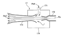
- FIG. 2 is a schematic diagram showing the ejector shown in FIG.
- the ejector 17 is pressurized by mixing the suction port 171 of the fourth return propane vapor Pb4, the introduction port 172 for introducing a part of the compressed propane vapor Pp cooled by the first cooling means 12, and the compressed propane vapor Pp.
- the fourth return propane vapor Pb 4 ′ has a discharge port 173 and a mixing chamber 174.
- the introduction port 172 and the discharge port 173 are opposed to each other with a predetermined interval inside the mixing chamber 174.
- a negative pressure is generated in the mixing chamber 174 by the injection pressure of the compressed propane vapor Pp introduced from the introduction port 172, and the fourth return propane vapor Pb4 is sucked into the suction port 171 by this negative pressure.
- the sucked fourth return propane vapor Pb4 is mixed together with the compressed propane vapor Pp toward the discharge port 173, and is discharged from the discharge port 173.
- the fourth return propane vapor Pb4 is heated and pressurized and discharged.
- a regulating valve 18 is provided in the upstream of the inlet 172 of the compressed propane vapor Pp in the ejector 17. Further, in the fourth return propane vapor Pb4 pipe 15-4, the pressure of the fourth return propane vapor Pb4 is detected, and the opening degree of the regulating valve 18 is controlled in accordance with the detection result. Is provided. Thereby, the introduction amount of the compressed propane vapor Pp to the ejector 17 is adjusted according to the pressure of the fourth return propane vapor Pb4.
- the pressure (that is, the absolute pressure) equivalent to the pressure of the third return propane steam Pb3 flowing through the pipe 15-3 on the high pressure stage side by one stage from the pipe 15-4 of the fourth return propane steam Pb4. Until the pressure of the fourth return propane vapor Pb4 is increased up to 130 kPaA).
- the piping 15-4 of the fourth return propane vapor Pb4 ′ and the piping 15-3 of the third return propane vapor Pb3 thus pressurized are connected to the downstream side of the separators 16-3 and 16-4.
- the returned propane vapor after joining is, for example, propane vapor having a temperature of ⁇ 35 ° C. and an absolute pressure of about 130 kPaA, and this propane vapor is sent to the most upstream stage (lowest pressure stage) in the compressor 11.
- the first return propane steam Pb1 and the second return propane steam Pb2 are sent as they are to the stages of the compressor 11 corresponding to the pressure of each return propane steam.
- the second return propane vapor Pb2 is sent to the downstream side (high-pressure stage side) of the combined return propane vapor in the compressor 11. Then, the first return propane vapor Pb1 is sent to the downstream side (high pressure stage side) of the second return propane vapor Pb2 in the compressor 11. These return propane vapors are compressed by the compressor 11 and again used for pre-cooling the raw material gas.
- the fourth return propane vapor Pb4 is pressurized by the ejector 17 so that the fourth return propane vapor Pb4 falls below the atmospheric pressure boiling point. Even if this steam is, the fourth return propane steam Pb4 can be adjusted to a predetermined pressure before being sent to the compressor 11. Thus, the circulation process can be operated within the physical limits of the compressor 11.
- the equipment configuration can be simplified and the pressure of the fourth return propane steam Pb4 can be adjusted without adding a new compressor or the like. Furthermore, by using the compressed propane vapor Pp in the circulation process as a driving medium, it is possible to improve the cooling performance of the entire cooling process without adding a separation device or the like.
- the following effects can be obtained when installed in a cold region.
- cold regions although the cooling efficiency of the raw material gas is relatively increased due to the low outside air temperature, if the lower limit value of the initial temperature of propane that can be introduced into the compressor 11 must be equal to or higher than the normal pressure boiling point, the cooling capacity Will be subject to restrictions.
- the fourth return propane vapor Pb4 on the low pressure stage side is sent to the compressor 11 after being pressurized and heated. For this reason, about the 4th return propane vapor
- an adjustment valve 18 that adjusts the introduction amount of the compressed propane vapor Pp according to the pressure of the fourth return propane vapor Pb4 is provided.
- the pressure of the fourth return propane vapor Pb4 can be increased to the optimum pressure as the input pressure to the compressor 11 regardless of the pressure of the fourth return propane vapor Pb4.
- the ejector 17 has the third return propane steam Pb3 flowing through the pipe 15-3 on the high-pressure stage side by one stage from the pipe 15-4 of the fourth return propane steam Pb4.
- the fourth return propane vapor Pb4 is pressurized to a pressure equivalent to the pressure of the (high pressure stage side return refrigerant vapor).
- the fourth return propane vapor Pb4 and the third return propane vapor Pb3 after pressurization are sent to the same stage in the compressor 11.
- the present invention is not limited to the above-described embodiment, and includes other configurations and the like that can achieve the object of the present invention, and the following modifications and the like are also included in the present invention.
- the refrigerant circulation system 1 installed in the liquefied natural gas (LNG) manufacturing facility has been described.
- the present invention is not limited to liquefied natural gas, but liquefied petroleum gas (LPG), liquefied nitrogen,
- LPG liquefied petroleum gas
- the present invention can be used as a refrigerant circulation system in any liquefied gas production facility such as liquefied oxygen.
- the refrigerant circulation system 1 adopting C3-MR is described as an example of the gas liquefaction process.
- the present invention is not limited to C3-MR, and the refrigerant circulation system adopting a cascade process or an expander process. Can also be used.
- the refrigerant circulation system 1 that cools the raw material gas as the cooling target gas has been described.
- the present invention is not limited to the raw material gas. It can also be used as a refrigerant circulation system that cools the mixed refrigerant as a cooling target gas.
- Refrigerant circulation system 11 Compressor (an example of compression means) 12 1st cooling means (an example of cooling means) 13 Second cooling means (an example of cooling means) 14 Storage tank 15-1, 15-2, 15-3, 15-4 Piping 17 Ejector 18 Adjusting valve (an example of adjusting means) 19 Controller Pb1 First return propane vapor Pb2 Second return propane vapor Pb3 Third return propane vapor Pb4 Fourth return propane vapor Pb4 ′ Pressurized fourth return propane vapor Pp Compressed propane vapor Pr Liquid propane
Landscapes
- Engineering & Computer Science (AREA)
- Physics & Mathematics (AREA)
- Mechanical Engineering (AREA)
- Thermal Sciences (AREA)
- General Engineering & Computer Science (AREA)
- Chemical & Material Sciences (AREA)
- Chemical Kinetics & Catalysis (AREA)
- General Chemical & Material Sciences (AREA)
- Oil, Petroleum & Natural Gas (AREA)
- Separation By Low-Temperature Treatments (AREA)
Abstract
単一成分冷媒による冷却プロセスにおいて、循環させる冷媒の運転圧力によって冷却能力を制限させることなく、冷却プロセス全体の冷却性能を高めることができる冷媒循環システムを提供する。冷媒循環システム(1)であって、コンプレッサー(11)と、圧縮したプロパンを冷却する第1の冷却手段(12)と、配管(15-1)、・・・(15-4)と、低圧段側の1つの配管(15-4)の途中に設けられて第4の戻りプロパン蒸気(Pb4)を加圧する加圧手段と、を備え、加圧手段は、第1の冷却手段(12)で冷却した圧縮プロパン蒸気(Pp)の一部を導入し、圧縮プロパン蒸気(Pp)の噴射圧によって第4の戻りプロパン蒸気(Pb4)を吸引するとともに、第4の戻りプロパン蒸気(Pb4)と圧縮プロパン蒸気(Pp)とを混合して加圧するエジェクター(17)であることを特徴とする。
Description
本発明は、原料ガスを冷却して液化し、液化ガスを製造するガス液化プロセスに利用される冷媒循環システムに関する。
従来、ガス液化プロセスとしては、単一成分冷媒(プロパン:C3)によって原料ガスを予冷(-30℃程度まで冷却)する予冷工程と、混合冷媒(窒素、メタン、エタン、プロパン等の混合物:MR)によって原料ガスを最終冷却(-160℃程度まで冷却)する最終冷却工程と、を備えたC3-MRプロセスが知られている。(例えば、特許文献1及び特許文献2参照。)。
予冷工程及び最終冷却工程の各冷却プロセスでは、冷媒を圧縮機(コンプレッサー)で圧縮し、圧縮した冷媒を冷却して凝縮させた後に、この冷媒を膨張、蒸発させつつ原料ガスと熱交換することで、原料ガスを冷却する。原料ガスを冷却して昇温した冷媒は、循環されて再び圧縮機に送られ、この循環を繰り返すことで、冷却プロセスが連続的に行われる。
原料ガスを冷却する際、常温(20℃程度)から予冷温度(-30℃程度)まで1段階の冷媒温度で冷却すると冷却効率が悪いため、原料ガスとの熱交換は複数段(例えば、4段)で行われる。このように複数段の冷却においては、原料ガス上流から下流に向かって順に低温となるように予冷冷媒の温度が設定されている。
一方、複数段で原料ガスを冷却した後の冷媒を再圧縮する際においては、温度が低い冷媒(低圧)から温度が高い冷媒(高圧)の順にそれぞれの圧力値に合った圧縮機中間段に導入して圧縮することによって圧縮機の圧縮効率を高めることができる。
ここで、単一成分冷媒(プロパン等)を用いる場合、その圧力(飽和蒸気圧)と温度(沸点)との関係は単一成分固有のものであり、一義的に決まることから、冷媒蒸気を圧縮機で加圧する際の第1段吸入圧力が最終冷却段温度によって決定され、圧縮機の要求性能が決定されてしまう。
圧縮機に導入される第1段の運転温度が低ければ低いほど、圧縮後の冷媒による冷却能力が高くなるものの、常圧沸点を下回るほど温度が低くなると冷媒蒸気体積が圧力に反比例して大きくなってしまうため、圧縮機の第1段吸入側サイズを非常に大きくしなければならない。
常圧沸点よりも低温かつ低圧な冷媒を導入して圧縮可能な圧縮機は、高段数かつ大型なものとなり、物理的な機器製作限界を超えてしまうか、機器製作コストが非常に増大してしまう。
また、寒冷地においては、外気温の低さによって原料ガスの冷却効率は相対的に上がるものの、圧縮機に導入可能な冷媒の初期温度の下限値が常圧沸点以上でなければならないとすると、予冷システムの冷却能力に制限を受けることになり、予冷冷媒圧縮機と混合冷媒圧縮機の能力バランスを最適にすることができず、冷却性能の向上に制約を受けることとなる。
本発明の目的は、単一成分冷媒による冷却プロセスにおいて、循環させる冷媒の運転圧力によって冷却能力を制限させることなく、冷却プロセス全体の冷却性能を高めることができる冷媒循環システムを提供することにある。
本発明の冷媒循環システムは、単一成分からなる冷媒を循環させて対象ガスを冷却する冷媒循環システムであって、前記冷媒を複数段で圧縮する圧縮手段と、前記圧縮手段で圧縮した冷媒を冷却する冷却手段と、前記対象ガスを冷却した後の戻り冷媒蒸気を複数段に分けて前記圧縮手段に送る複数の配管と、前記複数の配管のうち、少なくとも低圧段側の1つの配管の途中に設けられて前記戻り冷媒蒸気を加圧する加圧手段と、を備え、前記加圧手段は、前記冷却手段で冷却した圧縮冷媒蒸気の一部を導入し、該圧縮冷媒蒸気の噴射圧によって前記戻り冷媒蒸気を吸引するとともに、該戻り冷媒蒸気と前記圧縮冷媒蒸気とを混合して加圧するエジェクターであることを特徴とする。
以上のような本発明によれば、加圧手段によって戻り冷媒蒸気を加圧することで、戻り冷媒蒸気が常圧沸点を下回るような低温かつ低圧の蒸気となっている場合であっても、この戻り冷媒蒸気を所定の圧力に調整してから圧縮手段に送ることができる。従って、圧縮手段の物理的限界の範囲内で循環プロセスを運転することができる。また、冷却手段で冷却した圧縮冷媒蒸気の一部をエジェクターに導入し、この圧縮冷媒蒸気の噴射圧によって戻り冷媒蒸気を吸引するとともに、戻り冷媒蒸気と圧縮冷媒蒸気とを混合して加圧することで、圧縮手段を追加することなく戻り冷媒蒸気の圧力を調整することができる。さらに、循環プロセス内の圧縮冷媒蒸気を駆動媒体として利用することによって、分離装置等を追加することなく、冷却プロセス全体の冷却性能を高めることができる。
この際、本発明の冷媒循環システムでは、前記戻り冷媒蒸気の圧力に応じて、前記圧縮冷媒蒸気の前記加圧手段への導入量を調整する調整手段を備えることが好ましい。
この構成によれば、調整手段での調整により、戻り冷媒蒸気の圧力によらず圧縮手段への入力圧力として最適な圧力へと、その戻り冷媒蒸気の圧力を加圧することができる。
また、本発明の冷媒循環システムでは、前記加圧手段が、前記複数の配管のうち、前記1つの配管よりも所定段数だけ高圧段側の配管を流れる高圧段側戻り冷媒蒸気の圧力と同等な圧力まで、前記1つの配管を流れる前記戻り冷媒蒸気を加圧するものであり、前記加圧手段による加圧後の前記戻り冷媒蒸気と、前記高圧段側戻り冷媒蒸気とは、前記圧縮手段における互いに同じ段に送られることが好ましい。
この構成によれば、冷却の段数を増やして効率的な冷却を行いつつも、圧縮手段の段数の増加を抑えることで、設備コストの低減等を図ることがきる。
以上のような本発明の冷媒循環システムによれば、単一成分冷媒による冷却プロセスにおいて、循環させる冷媒の運転圧力によって冷却能力を制限させることなく、冷却プロセス全体の冷却性能を高めることができる。
以下、本発明の実施形態を図面に基づいて説明する。本実施形態の冷媒循環システム1は、液化天然ガス(LNG)の製造設備に設置される。本実施形態では、この製造設備におけるガス液化プロセスとして、単一成分冷媒(プロパン:C3)によって原料ガスを予冷(-30℃程度まで冷却)する予冷工程と、混合冷媒(窒素、メタン、エタン、プロパン等の混合物:MR)によって原料ガスを最終冷却(-160℃程度まで冷却)する最終冷却工程と、を備えたC3-MRプロセスが採用されている。本実施形態の冷媒循環システム1は、このC3-MRプロセスにおける予冷工程を担当する。
図1に示されているように、冷媒循環システム1は、プロパンを循環させて原料ガスを冷却するシステムであって、プロパン蒸気を複数段で圧縮するコンプレッサー11(圧縮手段)を備えている。コンプレッサー11での圧縮により、一例として温度が75℃、絶対圧が1850kPaA程度の圧縮プロパン蒸気となる。
コンプレッサー11の後段には、第1冷却手段12と第2冷却手段13とが設けられている。上記の圧縮プロパン蒸気は、第1冷却手段12により、一例として温度が55℃、絶対圧が1800kPaA程度の圧縮プロパン蒸気となる。さらに、その圧縮プロパン蒸気が、凝縮器としての第2冷却手段13での冷却により、一例として温度が50℃、絶対圧が1750kPaA程度のプロパン液となる。
第1冷却手段12での冷却を経た圧縮プロパン蒸気は、第2冷却手段13において液化して液体プロパンPrとなる。第2冷却手段13の下流には、冷媒バッファーとしての貯槽14が設けられている。その液体プロパンPrは、貯槽14から、原料ガスの予冷のために設けられた不図示の複数段の熱交換器へと送られる。各段の熱交換器において、液体プロパンPrは、各段に応じた圧力と温度で膨張、蒸発しつつ原料ガスと熱交換することで、原料ガスを各段に応じた温度に冷却する。本実施形態では、このような冷却が、4段に亘って行われる。
冷却を終えたプロパンは、再びプロパン蒸気となって冷媒循環システム1に戻ってくる。戻りプロパン蒸気は、温度が高く圧力が高いものから、第1の戻りプロパン蒸気Pb1から第4の戻りプロパン蒸気Pb4まで4段に分かれて戻ってくる。本実施形態では、第1の戻りプロパン蒸気Pb1が、一例として温度が-10℃、絶対圧が300kPaA程度のプロパン蒸気であり、第2の戻りプロパン蒸気Pb2が、一例として温度が-24℃、絶対圧が250kPaA程度のプロパン蒸気であり、第3の戻りプロパン蒸気Pb3が、一例として温度が-37.5℃、絶対圧が130kPaA程度のプロパン蒸気であり、第4の戻りプロパン蒸気Pb4が、一例として温度が-50℃、絶対圧が60kPaA程度のプロパン蒸気となっている。
第1~第4の戻りプロパン蒸気Pb1,Pb2,Pb3,Pb4は、各段の配管15-1,15-2,15-3,15-4によってコンプレッサー11に送られる。各段の配管15-1,15-2,15-3,15-4におけるコンプレッサー11の前段には、第1~第4の戻りプロパン蒸気Pb1,Pb2,Pb3,Pb4から液状成分を除去する分離器16-1,16-2,16-3,16-4が設けられている。各分離器16-1,16-2,16-3,16-4では、第1~第4の戻りプロパン蒸気Pb1,Pb2,Pb3,Pb4をワイヤーメッシュフィルタからなるミストエリミネーター161に通すことで、液状成分が除去される。除去後のドライな第1~第4の戻りプロパン蒸気Pb1,Pb2,Pb3,Pb4がコンプレッサー11に送られる。
ここで、本実施形態では、4つの配管15-1,15-2,15-3,15-4のうち、最も低圧段側(即ち、最も低温で低圧側)の1つの配管15-4における分離器16-4の前段となる途中の位置に、第4の戻りプロパン蒸気Pb4を加圧する加圧手段として、次のようなエジェクター17が設けられている。エジェクター17は、第1冷却手段12で冷却した温度が55℃、絶対圧が1800kPaA程度の圧縮プロパン蒸気Ppの一部を導入し、その圧縮プロパン蒸気Ppの噴射圧によって第4の戻りプロパン蒸気Pb4を吸引するとともに、第4の戻りプロパン蒸気Pb4と圧縮プロパン蒸気Ppとを混合して加圧する。
図2は、図1に示されているエジェクターを示す模式図である。エジェクター17は、第4の戻りプロパン蒸気Pb4の吸引口171と、第1冷却手段12で冷却した圧縮プロパン蒸気Ppの一部を導入する導入口172と、圧縮プロパン蒸気Ppとの混合によって加圧された第4の戻りプロパン蒸気Pb4’の排出口173と、混合室174とを有している。導入口172と排出口173とは、混合室174内部において所定間隔を空けて対向している。導入口172から導入される圧縮プロパン蒸気Ppの噴射圧によって混合室174内に負圧が生じ、この負圧によって吸引口171に第4の戻りプロパン蒸気Pb4が吸引される。吸引された第4の戻りプロパン蒸気Pb4は、圧縮プロパン蒸気Ppとともに排出口173へと向かって混合され、その排出口173から排出される。上記の混合により、第4の戻りプロパン蒸気Pb4は加熱されるとともに加圧されて排出される。
ここで、本実施形態では、図1に示されているように、エジェクター17における圧縮プロパン蒸気Ppの導入口172の前段に、調整弁18が設けられている。また、第4の戻りプロパン蒸気Pb4の配管15-4には、この第4の戻りプロパン蒸気Pb4の圧力を検知するとともに、その検知結果に応じて調整弁18の開度を制御する制御部19が設けられている。これにより、第4の戻りプロパン蒸気Pb4の圧力に応じて、圧縮プロパン蒸気Ppのエジェクター17への導入量が調整される。
本実施形態では、第4の戻りプロパン蒸気Pb4の配管15-4よりも1段だけ高圧段側の配管15-3を流れる第3の戻りプロパン蒸気Pb3の圧力と同等な圧力(即ち、絶対圧で130kPaA)まで、第4の戻りプロパン蒸気Pb4の圧力が加圧されるように、上記の調整弁18の開度が制御される。
このように加圧された第4の戻りプロパン蒸気Pb4’の配管15-4と、第3の戻りプロパン蒸気Pb3の配管15-3とは、各分離器16-3,16-4の後段側で合流する。合流後の戻りプロパン蒸気は、一例として温度が-35℃、絶対圧が130kPaA程度のプロパン蒸気であり、このプロパン蒸気が、コンプレッサー11における最上流段(最低圧段)に送られる。第1の戻りプロパン蒸気Pb1と第2の戻りプロパン蒸気Pb2は、そのまま、各戻りプロパン蒸気の圧力に応じたコンプレッサー11の各段に送られる。第2の戻りプロパン蒸気Pb2は、コンプレッサー11において、上記の合流後の戻りプロパン蒸気よりも下流側(高圧段側)に送られる。そして、第1の戻りプロパン蒸気Pb1が、コンプレッサー11において、第2の戻りプロパン蒸気Pb2よりも下流側(高圧段側)に送られる。これらの戻りプロパン蒸気がコンプレッサー11によって圧縮されて再度、原料ガスの予冷に供される。
以上に説明した本実施形態の冷媒循環システム1によれば、エジェクター17によって第4の戻りプロパン蒸気Pb4を加圧することで、第4の戻りプロパン蒸気Pb4が常圧沸点を下回るような低温かつ低圧の蒸気となっている場合であっても、この第4の戻りプロパン蒸気Pb4を所定の圧力に調整してからコンプレッサー11に送ることができる。従って、コンプレッサー11の物理的限界の範囲内で循環プロセスを運転することができる。また、第1冷却手段12で冷却した圧縮プロパン蒸気Ppの一部をエジェクター17に導入し、この圧縮プロパン蒸気Ppの噴射圧によって第4の戻りプロパン蒸気Pb4を吸引するとともに、第4の戻りプロパン蒸気Pb4と圧縮プロパン蒸気Ppとを混合して加圧することで、新たなコンプレッサー等を追加することなく機器構成を単純化して第4の戻りプロパン蒸気Pb4の圧力を調整することができる。さらに、循環プロセス内の圧縮プロパン蒸気Ppを駆動媒体として利用することによって、分離装置等を追加することなく、冷却プロセス全体の冷却性能を高めることができる。
また、本実施形態の冷媒循環システム1によれば、寒冷地に設置する場合に、次のような効果を得ることができる。寒冷地においては、外気温の低さによって原料ガスの冷却効率は相対的に上がるものの、コンプレッサー11に導入可能なプロパンの初期温度の下限値が常圧沸点以上でなければならないとすると、冷却能力に制限を受けることとなる。これに対し、本実施形態の冷媒循環システム1によれば、コンプレッサー11には、低圧段側の第4の戻りプロパン蒸気Pb4が加圧及び加熱されてから送られる。このため、第4の戻りプロパン蒸気Pb4については常圧沸点以下であってもコンプレッサー11に導入可能となっている。これにより、C3-MRの冷却プロセスにおける予冷冷媒圧縮機(本実施形態のコンプレッサー11)と不図示の混合冷媒圧縮機の能力バランスを最適にすることができ、冷却プロセス全体の冷却性能を向上させることができる。
また、本実施形態の冷媒循環システム1では、第4の戻りプロパン蒸気Pb4の圧力に応じて、圧縮プロパン蒸気Ppの導入量を調整する調整弁18が設けられている。これにより、第4の戻りプロパン蒸気Pb4の圧力によらずコンプレッサー11への入力圧力として最適な圧力へと、その第4の戻りプロパン蒸気Pb4の圧力を加圧することができる。
また、本実施形態の冷媒循環システム1では、エジェクター17が、第4の戻りプロパン蒸気Pb4の配管15-4よりも1段だけ高圧段側の配管15-3を流れる第3の戻りプロパン蒸気Pb3(高圧段側戻り冷媒蒸気)の圧力と同等な圧力まで、第4の戻りプロパン蒸気Pb4を加圧する。そして、加圧後の第4の戻りプロパン蒸気Pb4と、第3の戻りプロパン蒸気Pb3とは、コンプレッサー11における互いに同じ段に送られる。これにより、冷却の段数を増やして効率的な冷却を行いつつも、コンプレッサー11の段数の増加を抑えることで、設備コストの低減等が図られている。
なお、本発明は、前記実施形態に限定されるものではなく、本発明の目的が達成できる他の構成等を含み、以下に示すような変形等も本発明に含まれる。例えば、前記実施形態では、液化天然ガス(LNG)の製造設備に設置される冷媒循環システム1について説明したが、本発明は、液化天然ガスに限らず、液化石油ガス(LPG)や液化窒素、液化酸素など任意の液化ガスの製造設備における冷媒循環システムとして利用可能である。
また、前記実施形態では、ガス液化プロセスの一例としてC3-MRを採用した冷媒循環システム1について説明したが、本発明は、C3-MRに限らず、カスケードプロセスやエキスパンダープロセスを採用した冷媒循環システムとしても利用可能である。
また、前記実施形態では、冷却対象ガスとして原料ガスを冷却する冷媒循環システム1について説明したが、本発明は、原料ガスに限らず、例えばC3-MRにおける最終冷却系やシングルMRプロセス(SMR)における混合冷媒を冷却対象ガスとして冷却する冷媒循環システムとしても利用可能である。
また、前記実施形態では、単一成分からなる冷媒としてプロパンC3を用いる冷媒循環システム1について説明したが、本発明は、プロパンC3に限らず、他の軽炭化水素ガス(メタンC1、エタンC2、エチレンC2=、ブタンC4)を単一成分からなる冷媒として用いる冷媒循環システムとしても利用可能である。
その他、本発明を実施するための最良の構成、方法などは、以上の記載で開示されているが、本発明は、これに限定されるものではない。すなわち、本発明は、主に特定の実施形態に関して特に図示され、且つ、説明されているが、本発明の技術的思想および目的の範囲から逸脱することなく、以上述べた実施形態に対し、形状、材質、数量、その他の詳細な構成において、当業者が様々な変形を加えることができるものである。従って、上記に開示した形状、材質などを限定した記載は、本発明の理解を容易にするために例示的に記載したものであり、本発明を限定するものではないから、それらの形状、材質などの限定の一部、もしくは全部の限定を外した部材の名称での記載は、本発明に含まれるものである。
1 冷媒循環システム
11 コンプレッサー(圧縮手段の一例)
12 第1冷却手段(冷却手段の一例)
13 第2冷却手段(冷却手段の一例)
14 貯槽
15-1,15-2,15-3,15-4 配管
17 エジェクター
18 調整弁(調整手段の一例)
19 制御部
Pb1 第1の戻りプロパン蒸気
Pb2 第2の戻りプロパン蒸気
Pb3 第3の戻りプロパン蒸気
Pb4 第4の戻りプロパン蒸気
Pb4’ 加圧された第4の戻りプロパン蒸気
Pp 圧縮プロパン蒸気
Pr 液体プロパン
11 コンプレッサー(圧縮手段の一例)
12 第1冷却手段(冷却手段の一例)
13 第2冷却手段(冷却手段の一例)
14 貯槽
15-1,15-2,15-3,15-4 配管
17 エジェクター
18 調整弁(調整手段の一例)
19 制御部
Pb1 第1の戻りプロパン蒸気
Pb2 第2の戻りプロパン蒸気
Pb3 第3の戻りプロパン蒸気
Pb4 第4の戻りプロパン蒸気
Pb4’ 加圧された第4の戻りプロパン蒸気
Pp 圧縮プロパン蒸気
Pr 液体プロパン
Claims (3)
- 単一成分からなる冷媒を循環させて対象ガスを冷却する冷媒循環システムであって、
前記冷媒を複数段で圧縮する圧縮手段と、
前記圧縮手段で圧縮した冷媒を冷却する冷却手段と、
前記対象ガスを冷却した後の戻り冷媒蒸気を複数段に分けて前記圧縮手段に送る複数の配管と、
前記複数の配管のうち、少なくとも低圧段側の1つの配管の途中に設けられて前記戻り冷媒蒸気を加圧する加圧手段と、
を備え、
前記加圧手段は、前記冷却手段で冷却した圧縮冷媒蒸気の一部を導入し、該圧縮冷媒蒸気の噴射圧によって前記戻り冷媒蒸気を吸引するとともに、該戻り冷媒蒸気と前記圧縮冷媒蒸気とを混合して加圧するエジェクターであることを特徴とする冷媒循環システム。 - 前記戻り冷媒蒸気の圧力に応じて、前記圧縮冷媒蒸気の前記加圧手段への導入量を調整する調整手段を備えたことを特徴とする請求項1に記載の冷媒循環システム。
- 前記加圧手段が、前記複数の配管のうち、前記1つの配管よりも所定段数だけ高圧段側の配管を流れる高圧段側戻り冷媒蒸気の圧力と同等な圧力まで、前記1つの配管を流れる前記戻り冷媒蒸気を加圧するものであり、
前記加圧手段による加圧後の前記戻り冷媒蒸気と、前記高圧段側戻り冷媒蒸気とは、前記圧縮手段における互いに同じ段に送られることを特徴とする請求項1又は2に記載の冷媒循環システム。
Applications Claiming Priority (2)
| Application Number | Priority Date | Filing Date | Title |
|---|---|---|---|
| JP2015-057310 | 2015-03-20 | ||
| JP2015057310A JP2016176647A (ja) | 2015-03-20 | 2015-03-20 | 冷媒循環システム |
Publications (1)
| Publication Number | Publication Date |
|---|---|
| WO2016152651A1 true WO2016152651A1 (ja) | 2016-09-29 |
Family
ID=56977350
Family Applications (1)
| Application Number | Title | Priority Date | Filing Date |
|---|---|---|---|
| PCT/JP2016/058135 Ceased WO2016152651A1 (ja) | 2015-03-20 | 2016-03-15 | 冷媒循環システム |
Country Status (2)
| Country | Link |
|---|---|
| JP (1) | JP2016176647A (ja) |
| WO (1) | WO2016152651A1 (ja) |
Families Citing this family (1)
| Publication number | Priority date | Publication date | Assignee | Title |
|---|---|---|---|---|
| FR3112198B1 (fr) * | 2020-07-03 | 2022-07-22 | Air Liquide | Installation et procédé de réfrigération d’hydrogène |
Citations (3)
| Publication number | Priority date | Publication date | Assignee | Title |
|---|---|---|---|---|
| JPH10204455A (ja) * | 1997-01-27 | 1998-08-04 | Chiyoda Corp | 天然ガス液化方法 |
| US20070204649A1 (en) * | 2006-03-06 | 2007-09-06 | Sander Kaart | Refrigerant circuit |
| JP2011214741A (ja) * | 2010-03-31 | 2011-10-27 | Mitsubishi Electric Corp | 冷凍サイクル装置 |
-
2015
- 2015-03-20 JP JP2015057310A patent/JP2016176647A/ja active Pending
-
2016
- 2016-03-15 WO PCT/JP2016/058135 patent/WO2016152651A1/ja not_active Ceased
Patent Citations (3)
| Publication number | Priority date | Publication date | Assignee | Title |
|---|---|---|---|---|
| JPH10204455A (ja) * | 1997-01-27 | 1998-08-04 | Chiyoda Corp | 天然ガス液化方法 |
| US20070204649A1 (en) * | 2006-03-06 | 2007-09-06 | Sander Kaart | Refrigerant circuit |
| JP2011214741A (ja) * | 2010-03-31 | 2011-10-27 | Mitsubishi Electric Corp | 冷凍サイクル装置 |
Also Published As
| Publication number | Publication date |
|---|---|
| JP2016176647A (ja) | 2016-10-06 |
Similar Documents
| Publication | Publication Date | Title |
|---|---|---|
| JP6689277B2 (ja) | 天然ガスを液化するシステムおよび方法 | |
| US9746234B2 (en) | Mixed refrigerant compression circuit | |
| US10544986B2 (en) | Parallel compression in LNG plants using a double flow compressor | |
| US10180282B2 (en) | Parallel compression in LNG plants using a positive displacement compressor | |
| CN105102913A (zh) | 天然气液化方法和装置 | |
| US10663220B2 (en) | Multiple pressure mixed refrigerant cooling process and system | |
| US10753676B2 (en) | Multiple pressure mixed refrigerant cooling process | |
| US10323880B2 (en) | Mixed refrigerant cooling process and system | |
| CN108779953A (zh) | 用于液化天然气进料流的方法和系统 | |
| JP2010507771A (ja) | 炭化水素流を液化する方法及び装置 | |
| US10852059B2 (en) | Multiple pressure mixed refrigerant cooling system | |
| US20090188277A1 (en) | Method and apparatus for controlling a refrigerant compressor, and method for cooling a hydrocarbon stream | |
| WO2016152651A1 (ja) | 冷媒循環システム | |
| US20170160009A1 (en) | Gas liquefaction plant | |
| WO2016103296A1 (ja) | 冷凍装置 | |
| KR101686513B1 (ko) | 증발가스 재액화 장치 및 방법 | |
| TWI914766B (zh) | 低溫氣體冷卻系統和方法 |
Legal Events
| Date | Code | Title | Description |
|---|---|---|---|
| 121 | Ep: the epo has been informed by wipo that ep was designated in this application |
Ref document number: 16768554 Country of ref document: EP Kind code of ref document: A1 |
|
| NENP | Non-entry into the national phase |
Ref country code: DE |
|
| 122 | Ep: pct application non-entry in european phase |
Ref document number: 16768554 Country of ref document: EP Kind code of ref document: A1 |