WO2016152125A1 - 硬貨識別装置、及び、硬貨中心位置検出方法 - Google Patents
硬貨識別装置、及び、硬貨中心位置検出方法 Download PDFInfo
- Publication number
- WO2016152125A1 WO2016152125A1 PCT/JP2016/001575 JP2016001575W WO2016152125A1 WO 2016152125 A1 WO2016152125 A1 WO 2016152125A1 JP 2016001575 W JP2016001575 W JP 2016001575W WO 2016152125 A1 WO2016152125 A1 WO 2016152125A1
- Authority
- WO
- WIPO (PCT)
- Prior art keywords
- coordinate
- coin
- center
- edge
- edge point
- Prior art date
- Legal status (The legal status is an assumption and is not a legal conclusion. Google has not performed a legal analysis and makes no representation as to the accuracy of the status listed.)
- Ceased
Links
Images




Classifications
-
- G—PHYSICS
- G07—CHECKING-DEVICES
- G07D—HANDLING OF COINS OR VALUABLE PAPERS, e.g. TESTING, SORTING BY DENOMINATIONS, COUNTING, DISPENSING, CHANGING OR DEPOSITING
- G07D5/00—Testing specially adapted to determine the identity or genuineness of coins, e.g. for segregating coins which are unacceptable or alien to a currency
- G07D5/02—Testing the dimensions, e.g. thickness, diameter; Testing the deformation
Definitions
- the present invention relates to a coin center position detection method for detecting a coin center in a coin image obtained by imaging a coin in a coin identification device, and can detect a coin center position in a coin image with a simple calculation with high accuracy. It is about the method.
- Patent Document 1 describes an apparatus for calculating the outer diameter of a coin.
- This device is configured to convey coins by a belt wound around a pulley, and includes a light-shielding sensor disposed in the middle of the conveyance path.
- This device measures the lengths of two strings parallel to each other at two locations of a circle formed by the outer periphery of the coin based on the detection result of the sensor and the rotation information of the pulley.
- This apparatus calculates the outer diameter of a coin using a geometric relational expression based on the measured lengths of two strings.
- Patent Document 2 describes a device that calculates the outer diameter of a coin being conveyed in a predetermined direction and detects the center position of the coin.
- This device is also provided with a sensor that is disposed in the middle of the transport path and detects a coin, and based on the time when the sensor detects the coin and information on the transport speed of the coin, The lengths of two strings parallel to each other are measured at two points of a circle formed by the outer peripheral edge.
- This apparatus calculates the outer diameter of the coin and detects the center position of the coin using a geometric relational expression based on the measured lengths of the two strings.
- the apparatus described in patent document 1 and 2 is integrated in the identification apparatus of the coin processing apparatus which performs various processes regarding a coin, for example, and the outer diameter of the coin which this apparatus calculates, or an outer diameter The center position is used for identifying coins.
- the technology disclosed herein has been made in view of the above points, and an object thereof is to shorten the calculation time required to detect the center position when the center position of the coin is detected.
- the technology disclosed herein relates to a coin identification device, which picks up an image of the entire coin while it is being transported and a transport unit configured to transport coins in the Y direction.
- the center X coordinate Based on the image captured by the image capture unit and the image captured by the image capture unit, the center X coordinate configured to acquire the center X coordinate of the coin in the X direction orthogonal to the Y direction in the image
- An acquisition unit, a diameter information acquisition unit configured to acquire a size of the diameter of the coin in the image captured by the imaging unit, and an outer peripheral edge of the coin in the image captured by the imaging unit.
- An edge point information acquisition unit configured to acquire the X coordinate and the Y coordinate of the edge point, and the center X coordinate, the size of the diameter, and the X coordinate and the Y coordinate of the edge point, In the Y direction of the coin
- An arithmetic unit configured for calculating a center Y coordinate of Te comprises a.
- the calculation unit uses an approximate expression obtained by approximating a geometric relational expression formed between the center of the circle and a point on the circumference by a polynomial, and calculates the center X coordinate and the X coordinate of the edge point.
- a center Y coordinate in the Y direction is calculated from the difference, the size of the diameter, and the Y coordinate of the edge point.
- the coin is transported in the Y direction by the transport unit, and the imaging unit captures the entire image while the coin is being transported.
- the transport unit is, for example, a belt arranged so as to extend along the coin transport direction, and while the coin is running while holding the coin in contact with the front or back surface of the coin, You may comprise and comprise the conveyance belt comprised so that it may convey. Moreover, you may comprise so that the pin and nail
- the imaging unit may be configured to include an image sensor, and the image sensor extends in the X direction orthogonal to the Y direction, for example, and captures an image of the entire coin by capturing in synchronization with the coin transport. It is good also as a line sensor comprised so that it may image. Further, the image sensor may be an area sensor that extends in each of the X direction and the Y direction and is configured to capture an image of the entire coin at once.
- the center X coordinate acquisition unit and the diameter information acquisition unit respectively acquire the center X coordinate of the coin in the X direction and the diameter of the coin based on the image captured by the imaging unit.
- the center X coordinate acquisition unit and the diameter information acquisition unit for example, set the luminance value of each pixel to Y for each pixel column arranged in the X direction in an image of the entire coin having a predetermined number of pixels in each of the X direction and the Y direction. It is possible to acquire the center X coordinate of the coin and the size of the diameter of the coin from a luminance histogram composed of values added in the direction (that is, a luminance histogram in the X direction).
- the luminance histogram By using the luminance histogram, it is possible to acquire the center X coordinate of the coin and the size of the diameter of the coin in a short time. In addition, by using the luminance histogram in the X direction, the coordinates of the edge points on the outer periphery of the coin can be acquired relatively accurately without being affected by the above-described transport belt extending in the Y direction. become. As a result, the center X coordinate of the coin and the size of the diameter of the coin can each be obtained with high accuracy.
- the edge point information acquisition unit acquires the X coordinate and the Y coordinate of the coin edge point (that is, a point on the outer periphery) based on the image captured by the imaging unit. For example, the edge point information acquisition unit acquires the X coordinate and the Y coordinate of the edge point from the luminance histogram in the Y direction.
- the luminance histogram in the Y direction is composed of values obtained by adding the luminance values of the pixels in the X direction for the pixel columns arranged in the Y direction in the image of the entire coin.
- the calculation unit calculates the center Y of the coin in the Y direction. Calculate coordinates.
- the operation unit performs an operation using an approximate expression obtained by approximating a geometric relational expression formed between the center of the circle and a point on the circumference with a polynomial.
- the geometric relational expression is, for example, a three-square theorem, and if used as it is, the arithmetic expression includes a square root.
- the calculation unit uses an approximate expression that does not include a square root. This reduces the calculation processing load of the calculation unit and reduces the time required for calculation. Therefore, this coin identification device can satisfy the requirement of shortening the time required to calculate the center position.
- the edge point information acquisition unit acquires coordinates of at least three edge points
- the coin identification device is configured to select one or two edge points from the at least three edge points.
- An edge point selection unit calculates the center Y coordinate based on the one or two edge points selected by the edge point selection unit, the edge point selection unit, About the edge point, the reliability of whether the point is on the circumference determined based on the center X coordinate acquired by the center X coordinate acquisition unit and the size of the diameter acquired by the diameter information acquisition unit May be determined using the approximate expression and an edge point may be selected based on the reliability.
- the edge point information acquisition unit acquires the X coordinate and the Y coordinate of the edge point based on the image captured by the imaging unit. If the Y coordinate of the edge point is not accurate, the edge point information acquisition unit calculates the coin using the approximate expression. The center Y coordinate is also not accurate.
- the edge point information acquisition unit acquires the X coordinate and the Y coordinate of the edge point based on the luminance histogram in the Y direction
- the luminance histogram in the Y direction is narrow so as to avoid the above-described conveyance belt.
- the luminance value of each pixel must be added for each pixel column. For this reason, an error is likely to be included in the Y coordinate of the edge point acquired from the luminance histogram in the Y direction.
- the edge point information acquisition unit acquires the coordinates of at least three edge points. These edge points are candidates for edge points used when calculating the center Y coordinate of the coin.
- the edge point selection unit determines the reliability of each of the plurality of edge points as a point on the circumference, and selects one or two edge points based on the reliability. Since the calculation unit calculates the center Y coordinate of the coin using the approximate expression from the edge point selected based on the reliability, the accuracy of the center Y coordinate of the coin is improved.
- the edge point selection unit uses an approximate expression when determining the reliability of whether the edge point is a point on the circumference. For this reason, it is possible to shorten the time required for the determination. After selecting an edge point from a plurality of edge points based on reliability, the time until the center Y coordinate of the coin is calculated is shortened.
- the edge point selection unit includes two edges based on the Y coordinate acquired by the edge point information acquisition unit for two edge points arbitrarily selected from the edge points acquired by the edge point information acquisition unit. By comparing the distance in the Y direction between the points and the distance in the Y direction between the two edge points calculated using the approximate expression based on the X coordinate acquired by the edge point information acquisition unit, the reliability The degree may be judged.
- the edge point information acquisition unit acquires the X coordinate and the Y coordinate of the edge point based on a luminance histogram in the Y direction
- the Y coordinate easily includes an error
- the X coordinate includes an error. Absent. Therefore, two edges calculated using an approximate expression based on the Y-direction distance between two edge points based on the Y coordinate acquired by the edge point information acquisition unit and the X coordinate acquired by the edge point information acquisition unit. By comparing the distance in the Y direction between the points, it becomes possible to evaluate the reliability of the Y coordinates of the two edge points.
- the edge point information acquisition unit has the X coordinate and the Y coordinate of the two edge points of the edge point corresponding to the front side and the edge point corresponding to the rear side of the coin conveyed in the Y direction while the X coordinates coincide with each other. At least the coordinates are obtained, and when the edge point selection unit selects two edge points with the same X coordinate, the calculation unit selects instead of calculating the center Y coordinate using the approximate expression.
- the midpoint of the Y coordinates of the two edge points may be the center Y coordinate.
- the calculation time of the coin based on the Y coordinates of the two edge points is reduced, and the calculation of the center Y coordinate is accurate. Increases the nature. Therefore, when two edge points having the same X coordinate are extracted, instead of calculating the center Y coordinate in the Y direction of the coin using an approximate expression, the middle point of the Y coordinate of the two edge points is determined as a coin. To the center Y coordinate. This shortens the calculation time and increases the accuracy of the center Y coordinate.
- two edge points having the same X coordinate can be acquired based on one luminance histogram in the Y direction created for a predetermined section in the X direction.
- the edge point information acquisition unit acquires at least two X coordinates and Y coordinates of edge points having different positive and negative X coordinates and Y coordinates when the center of the coin is assumed to be an origin.
- Center coordinates may be calculated from a perpendicular bisector with respect to an edge point and the center X coordinate acquired by the center X coordinate acquisition unit.
- the two edge points having different positive and negative X coordinates and Y coordinates correspond to the front edge point and the rear edge point of the coin conveyed in the Y direction.
- the center Y coordinate of the coin is calculated from the perpendicular bisector for the two edge points and the center X coordinate of the coin. This makes it possible to accurately calculate the center Y coordinate of the coin while shortening the time required for the calculation with a small amount of calculation.
- the distance in the Y direction between the front edge point and the rear edge point of the coins conveyed in the Y direction is relatively long. As described above, when the reliability is determined based on the distance in the Y direction between the two edge points, an accurate determination can be made.
- the approximate expression may be set in a predetermined angle range with respect to the center of the coin, and the calculation unit may calculate the center Y coordinate based on an edge point included in the predetermined angle range.
- the predetermined angle range may be set as an angle range in which a predetermined accuracy can be ensured by an approximate expression approximated by a polynomial.
- the coin discriminating apparatus disclosed herein also includes a transport unit configured to transport coins in the Y direction, an imaging unit configured to capture an image of the entire coin during transport, and an image. Based on the image, a center X coordinate acquisition unit configured to acquire a center X coordinate of the coin in the X direction orthogonal to the Y direction in the image, and in the captured image, the diameter of the coin A diameter information acquisition unit configured to acquire a size and an X coordinate and a Y coordinate of at least three edge points that are points on the outer periphery of the coin, respectively, in the captured image.
- An edge point information acquisition unit configured to acquire one or two edge points from the at least three edge points, the center X coordinate, the size of the diameter, Beauty, from the X and Y coordinates of the edge points, and a computing unit configured for calculating a center Y coordinate in the Y direction of the coin.
- the said edge point selection part is based on the magnitude
- the reliability of whether or not the point is on the circumference determined is determined, and the edge point is selected based on the reliability.
- the calculation unit By calculating the center Y coordinate, the accuracy of the center Y coordinate is improved, and as a result, the center position of the coin can be accurately determined together with the accurate center X coordinate acquired by the center X coordinate acquisition unit.
- the edge point selection unit may determine the reliability using an approximate expression obtained by approximating a geometric relational expression established between a center of a circle and a point on the circumference by a polynomial.
- Calculation time can be shortened by judging the reliability of multiple edge points using an approximate expression that approximates the geometric relation between the center of the circle and points on the circumference with a polynomial. Figured.
- the coin center position detection method disclosed herein includes a step of capturing an image of the entire coin while the coin is being conveyed in the Y direction, and an X direction orthogonal to the Y direction based on the captured image. Obtaining a center X coordinate of the coin in the image, obtaining a size of the diameter of the coin based on the captured image, and based on the captured image From the step of obtaining the X coordinate and Y coordinate of the edge point which is a point on the outer periphery of the coin, the center X coordinate, the size of the diameter, and the X coordinate and Y coordinate of the edge point, the coin Calculating a center Y coordinate with respect to the Y direction, wherein the step of calculating the center Y coordinate uses a polynomial to express a geometric relation between a circle center and a point on the circumference as a polynomial. Approximation The center Y coordinate of the coin in the Y direction is calculated from the difference between the center X coordinate and the X coordinate
- the coin center position detection method different from the above is based on the step of capturing an image of the entire coin while the coin is being conveyed in the Y direction, and orthogonal to the Y direction in the image based on the captured image.
- the calculation time for detecting the center position can be shortened.
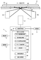
- FIG. 1 is a conceptual diagram illustrating a configuration of a coin transport unit and an imaging unit in a coin identification device.
- FIG. 2 is a block diagram showing the configuration of the coin identifying device including the II-II cross-sectional view of FIG.
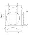
- FIG. 3 is a diagram illustrating a luminance histogram created from a coin image.
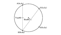
- FIG. 4 is an explanatory diagram showing the geometric relationship between the points used for the calculation of the center coordinates of the coin.
- FIG. 5 is a diagram for explaining a method of calculating the center Y coordinate of a coin from two edge points.
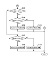
- FIG. 6 is a part of a flowchart relating to the calculation of the center coordinates of the coin.
- FIG. 7 is a part of a flowchart relating to the calculation of the center coordinates of the coin.
- FIG. 8 is a diagram illustrating a configuration of a coin processing device having a coin identifying device.
- This coin identifying device is a device that is incorporated in a coin processing device that performs various processes and is used for identifying coins.
- FIG. 8 illustrates the configuration of a coin processing device 100 having a coin identifying device.
- the coin processing apparatus 100 is configured to store, for example, each denomination after identifying the inserted loose coins.
- the loose coins inserted from a deposit port (not shown) are fed one by one to the transport unit 2 by a feeding mechanism 27 having two disks.
- the transport unit 2 includes a transport belt 23 that transports coins from the left to the right in FIG. 8 and a second transport belt 26 that transports coins from the bottom to the top of the page.
- a magnetic sensor 29 and an image sensor are disposed in order to detect the properties of coins.
- an exclusion hole 25a for removing the fouling coins and other coins, for the creation of new coins and for a large amount of denominations are provided with an optional denomination selection hole 25b and holes 25c to 25h for each denomination.
- Coins conveyed along the second conveyance path 28 by the second conveyance belt 26 fall downward from any of the holes 25a to 25h based on the identification result of the coin identification device 1.
- the coins dropped from the holes 25b to 25h are stored in different storages (not shown).
- the coin identification by the coin identification device 1 is performed by pattern matching using the image of the entire coin imaged by the imaging unit 3 (however, in addition to the pattern matching, the coin is identified by the magnetic sensor 29). This is done in consideration of the material of the coin based on the detection result by the above).
- pattern matching an image of a coin is cut out in a ring shape surrounded by two concentric circles centered on the center position of the coin (however, the cut out image includes the outer peripheral edge of the coin), and a ring shape
- An image obtained by polar-coordinate conversion of the image cut out is used.
- a method for detecting the center position of a coin that is, the provisional center position
- the coin identification device 1 cuts out an image of the coin and performs polar coordinate conversion will be described in detail.
- the coin identification device 1 includes a transport unit 2 that transports the coin 10 in the Y direction, an image capturing unit 3 that captures an image of the entire transported coin 10, and the control of the transport unit 2 and the image capturing unit 3. And a control unit 4 that performs various types of control (including various calculations for determining the center position of the coin 10).
- the conveyance unit 2 has a conveyance path 21 that extends in the Y direction (that is, the vertical direction in FIG. 1 and corresponds to the horizontal direction in FIG. 2) and the coin 10 is conveyed.
- the conveyance path 21 has a guide 22 on one side in the X direction orthogonal to the Y direction (that is, the left side in FIG. 1).
- the coin 10 is transported in a state where the coin 10 is brought close to one side in the X direction and is in contact with the guide 22.
- the transport unit 2 has a transport belt 23 for transporting the coins 10.
- the conveyance belt 23 extends in the Y direction along the conveyance path 21.
- the conveyance belt 23 is an endless belt wound around two pulleys, although not shown.
- the conveyance belt 23 is shifted to the other side in the X direction (that is, the right side in FIG. 1) with respect to the center of the coin 10 conveyed in a state of being close to one side in the X direction so as to contact the guide 22. In contact with the coin 10.
- the transport belt 23 travels along the transport path 21, the coin 10 is transported along the transport path 21 in the Y direction along with the transport belt 23.
- pins and claws are provided at a predetermined interval with respect to the conveyor belt 23, and these pins and claws push the rear end portion of the coin 10 as the conveyor belt 23 travels.
- the drawing is illustrated as transporting only one coin 10, but the plurality of coins 10 substantially contact the front edge and the rear edge. In such a state, it may be conveyed on the conveyance path 21 side by side in the Y direction.
- the imaging unit 3 is disposed below the conveyance path 21.
- a part of the conveyance path 21 is configured by a window portion 24 made of a translucent material.
- the imaging unit 3 is disposed directly below the window 24.
- the imaging unit 3 has an image sensor 31.
- the image sensor 31 is configured by a line sensor extending in the X direction or an area sensor extending in each of the X direction and the Y direction.
- the imaging unit 3 also has an illumination unit 32 that irradiates the lower surface of the coin 10 that passes through the window unit 24.
- the illumination unit 32 is configured in a ring shape so that the coin 10 is irradiated with light from the entire outer periphery.
- the illumination unit 32 also has two types of light sources so that the coin 10 is irradiated with light from two angles, a small angle and a large angle, as indicated by arrows in FIG. Thereby, it becomes possible to image clearly the pattern provided on the front surface or the back surface of the coin 10.
- Each of the two types of light sources is constituted by, for example, an LED.
- the illumination unit 32 emits light in synchronization with the conveyance of coins passing through the window unit 24.
- the image sensor 31 images the reflected light from the coin 10.
- the image sensor 31 acquires an entire image of the coin 10 by performing imaging in synchronization with the conveyance of the coin 10.
- the number of pixels of the image captured by the image sensor 31 is, for example, 256 pixels in the X direction and 240 pixels in the Y direction.
- the control unit 4 functions as a functional block related to the detection of the center position of the coin 10.
- the image acquisition unit 41 acquires an image captured by the imaging unit 3, and the temporary center of the coin from the image acquired by the image acquisition unit 41.
- a processing unit 44 is included.
- the control unit 4 is configured based on, for example, a known microcomputer. Although details will be described later, the temporary center determination unit 42 includes the following functional blocks.
- the center X coordinate acquisition unit 421 that acquires the center coordinates in the X direction of the coin from the image of the coin 10
- the diameter information acquisition unit 422 that acquires the size of the diameter of the coin 10 from the image of the coin 10 from the image of the coin 10
- the coin 10 From the above image, at each of the two preset X coordinate positions, an edge point on the outer periphery corresponding to the front side of the coin 10 conveyed in the Y direction, and an edge point on the outer periphery corresponding to the rear side
- An edge point information acquisition unit 423 that acquires the X and Y coordinates of the two edge points
- an edge point selection unit 424 that selects one or two reliable edge points from the acquired edge points
- a selection The calculation unit 425 calculates the coordinates of the temporary center of the coin 10 based on the edge point.
- control unit 4 Also connected to the control unit 4 is a storage unit 5 for storing various information.
- the control unit 4 performs calculations or the like while using the information stored in the storage unit 5 and stores the calculation results and the like in the storage unit 5.
- the image acquisition unit 41 converts an image captured by the image sensor 31 into a 256 ⁇ 256 digitized image, for example, by decomposing the brightness into luminance values of 256 gradations for each pixel.
- image of a coin means this digitized image.
- FIG. 3 illustrates an image im of the coin 10.
- the image im of the coin 10 includes, for example, 256 pixels in the X direction and 256 pixels in the Y direction.
- the temporary center determining unit 42 creates a luminance histogram Hhist in the X direction (that is, horizontal direction) and a luminance histogram Vhist in the Y direction (that is, vertical direction) based on the image im of the coin 10.
- the luminance histogram Hhist in the X direction is obtained by sequentially arranging luminance frequencies obtained by summing the luminance values of the respective pixels in the horizontal direction for each pixel column extending in the vertical direction.
- the luminance frequency is the sum of the luminance values of the pixels included in the preset sections H T to H B.
- the sections H T to H B the front end portion and the rear end portion of the coin 10 conveyed in the Y direction are excluded so that the contact portion between the coins conveyed in the Y direction is not affected. Is set. Further, by setting the sections H T to H B so as to exclude the front end portion and the rear end portion, the luminance histogram Hhist in the X direction indicates that the conveyor belt 23 indicated by a broken line in FIG. 3 appears in the image im. Not affected.
- the luminance histogram Vhist in the Y direction is obtained by sequentially arranging the luminance frequencies obtained by summing the luminance values of the respective pixels in the vertical direction for each pixel column extending in the horizontal direction.
- the conventional temporary center determination unit creates only a luminance histogram obtained by summing the luminance values of the pixels included in the preset sections V L1 to V R1 as the Y-direction luminance histogram Vhist.
- the influence of the conveyance belt 23 indicated by the broken line in FIG. 3 being reflected in the image im is not affected by the contact portion between the coins conveyed in the Y direction. It is set not to receive.
- the sections V L1 to V R1 are set as sections that are not easily affected by metal powder or dust generated by the wear of the coin 10 or the like. That is, while the conveyance of the coin 10 is repeated, the metal powder generated due to the wear of the coin 10 or the like may remain on the conveyance path 21 and the metal powder may appear in the image im.
- the coin 10 since the coin 10 is transported toward the guide 22, the coin 10 always moves on one side in the X direction in the transport path 21 (corresponding to the left side in FIG. 3). The generated metal powder or the like hardly moves on the transport path 21 by moving together with the coin 10.
- the other side in the X direction in the transport path 21 (corresponding to the right side in FIG.
- the temporary center determining unit 42 of the coin center position determining device disclosed herein includes not only the luminance histograms of the sections V L1 to V R1 as the Y-direction luminance histogram Vhist but also the transport path 21.
- a luminance histogram of intervals V L2 to V R2 corresponding to the other side in the X direction is also created. That is, the temporary center determination unit 42 creates two Y-direction luminance histograms Vhist.
- the influence of the conveyance belt 23 indicated by the broken line in FIG. 3 being reflected in the image im is not affected by the contact portion between the coins conveyed in the Y direction. This section is set so as not to receive.
- the center X coordinate acquisition unit 421 acquires the center coordinates of the coin 10 in the X direction based on the luminance histogram Hhist in the X direction. Specifically, the center X coordinate acquisition unit 421 determines a point on the outer peripheral edge of the coin 10, that is, an edge point, based on the luminance histogram Hhist in the X direction. For example, as shown in FIG. 3, the edge point is determined by comparing a preset threshold value TH with the luminance frequency of the luminance histogram, and by comparing the X coordinate value with which the luminance frequency is smaller than the threshold value.
- the diameter information acquisition unit 422 also acquires the center coordinates of the coin 10 in the X direction based on the luminance histogram Hhist in the X direction. Specifically, the diameter information acquisition unit 422 sets the difference (
- ) between the edge points XL and XR determined based on the luminance histogram Hhist in the X direction as the diameter 2r of the coin 10 ( That is, 2r
- the luminance histogram Hhist in the X direction does not affect the contact portion of coins conveyed in a state of being aligned in the Y direction, and the influence of the conveyance belt 23 appearing in the image im. It is possible to set and create a relatively wide section H T to H B , while the section H T to H B is the X direction in the coin 10 conveyed in the Y direction. It is possible to set including the maximum width portion. Therefore, based on the luminance histogram Hhist in the X direction, the center X coordinate xc of the coin 10 and the diameter 2r of the coin 10 can be obtained with high accuracy.
- the conventional temporary center determining unit creates only the luminance histogram obtained by summing the luminance values of the pixels included in the preset sections V L1 to V R1 as the Y-direction luminance histogram Vhist.
- the luminance histogram Vhist in the Y direction constraints upon setting of the section V L1 ⁇ V R1 is large, the interval V L1 ⁇ V R1 becomes relatively narrow. For this reason, the error of the edge points YT 1 and YB 1 determined based on the luminance histogram Vhist in the Y direction tends to increase.
- the state of the coin 10, for example in new currency dirt is small coin 10, the light irradiated by the illumination unit 32, in the interval V L1 ⁇ V R1, the coin 10
- the imaging state of the outer peripheral edge of the coin 10 may become unclear in the image captured by the imaging unit 3.
- the accuracy may decrease.
- the center Y coordinate of the coin 10 is not calculated based on only one Y-direction luminance histogram Vhist, but a plurality of edges obtained from the Y-direction luminance histogram Vhist. After selecting a highly reliable edge point from the point candidates, the center Y coordinate of the coin 10 is calculated based on the selected edge point.
- the edge point information acquisition unit 423 determines the edge points YT 1 and YB 1 based on the luminance histogram in the Y direction of the sections V L1 to V R1 .
- the edge points YT 1 and YB 1 are determined by comparing a preset threshold value TH with the luminance frequency of the luminance histogram.
- the edge points YT 1 and YB 1 are determined in this way, as shown in FIG. 4, the edge point A (Ax, Ay) and the edge point B (Bx, By) are determined as edge point candidates.
- X-coordinate Ax edge point A is determined by the edge point YT 1 determined from the luminance histogram of the Y-direction.
- Y coordinate By is determined by the edge point YB 1 determined from the luminance histogram of the Y-direction.
- the edge point A (Ax, Ay) and the edge point B (Bx, By) have the same X coordinate and the edge point corresponding to the front side of the coin 10 conveyed in the Y direction, and the rear side.
- the edge point information acquisition unit 423 determines the edge points YT 2 and YB 2 based on the luminance histogram in the Y direction of the sections V L2 to V R2 .
- the edge points YT 1 and YB 1 are determined, as shown in FIG. 4, the edge point C (Cx, Cy) and the edge point D (Dx, Dy) are determined as edge point candidates.
- X-coordinate Cx edge point C as can be seen from Figures 3 and 4, Sadamari by V L2 defining the interval
- Y coordinate Cy is determined by the edge point YT 2 determined from the luminance histogram of the Y-direction.
- X coordinates Dx edge point D is Sadamari by V L2 defining the interval
- Y coordinate Dy is determined by the edge point YB 2 determined from the luminance histogram of the Y-direction.
- the edge point C (Cx, Cy) and the edge point D (Dx, Dy) coincide with each other in the X coordinate and the edge point corresponding to the front side of the coin 10 conveyed in the Y direction, and the rear side.
- the edge point information acquisition unit 423 acquires the X coordinate and the Y coordinate of the four points of the edge points A, B, C, and D as the edge point candidates.
- the value of the X coordinate of each edge point is a value determined from the configuration of the image sensor 31, it is accurate.
- the value of the Y coordinate of each edge point is YT 1 , YB 1 , YT 2 , and YB 2 determined based on the luminance histogram in the Y direction, and thus may include an error.
- the edge point selection unit 424 evaluates the reliability of the four edge points acquired by the edge point information acquisition unit 423, and selects two or one edge point from them. Since all four edge points are points that should be located on the circumference, the edge point selection unit 424 uses the center X coordinate acquired by the center X coordinate acquisition unit 421 and the diameter information acquisition unit as reliability evaluations. Whether the X and Y coordinates of each edge point satisfy the geometrical relationship established between the center of the circle and the point on the circumference based on the diameter 2r of the coin 10 acquired by 422 , Evaluate.
- FIG. 4 shows the geometric relationship between the four edge points (A, B, C, D) and the center of the coin 10.
- r is obtained from the luminance histogram Hhist in the X direction by the diameter information acquisition unit 422
- Lx is the center X coordinate Xc obtained from the luminance histogram Hhist in the X direction by the central X coordinate acquisition unit 421.
- the approximate expression (3) can be used when the central angle ⁇ is 30 ° ⁇ ⁇ ⁇ 90 ° (that is, the approximation accuracy is high). When the central angle is less than 30 °, the accuracy of the approximate expression represented by Expression (3) is lowered. Moreover, although it is possible to use an approximate expression that can be used when the central angle ⁇ is in the range of 0 ° ⁇ ⁇ ⁇ 90 °, in that case, the accuracy of the approximate expression decreases.
- the edge points A, B, C, and D acquired by the edge point information acquisition unit 423 have a center angle ⁇ of 30 ° ⁇ ⁇ ⁇ 90 ° so that the approximate expression shown in Equation (3) can be used. For this reason, the sections V L1 to V R1 and the sections V L2 to V R2 when the luminance histogram Vhist in the Y direction is created are set as appropriate.
- L is equivalent to the distance in the Y direction between the edge point A and the center of the circle (or the distance in the Y direction between the edge point B and the center of the circle), and M is the edge point C. And the center of the circle in the Y direction (or the distance in the Y direction between the edge point D and the center of the circle).
- Both L and M can be calculated without using a value based on the luminance histogram Vhist in the Y direction. Therefore, the edge point selection unit 424 uses the edge points A, B, C, and D determined based on the L and M, etc. calculated using the equations (4) and (5) and the luminance histogram Vhist in the Y direction. The reliability of each edge point is evaluated by comparing with the value of the Y coordinate.
- FIGS. 6 and 7 are flowcharts showing the procedure from the selection of the edge point to the calculation of the center Y coordinate of the coin 10, which is executed by the edge point selection unit 424 and the calculation unit 425.
- step S1 it is determined whether or not the center angle ⁇ of the edge point C and the edge point D is less than 30 °. When the angle is less than 30 °, Expression (5) based on the above-described approximate expression cannot be used. Therefore, when the determination in step S1 is YES, it is determined that the reliability of the edge point A and the edge point B is high, the process proceeds to step S7, and the edge point A and the edge point B are selected.
- Ay is determined by the edge point YT 1 determined from the luminance histogram in the Y direction
- By is determined by the edge point YB 1 determined from the luminance histogram in the Y direction.
- the center Y coordinate of the coin 10 is set based on the luminance histogram Vhist in the Y direction in the sections V L1 to V R1 . The flow then ends.
- the central Y coordinate of the coin 10 is determined in step S8. This is set based on the luminance histogram Vhist in the Y direction in the sections V L2 to V R2 .
- step S3 it is determined whether DiffAB is equal to or less than a predetermined number of pixels P1.
- DiffAB DiffAB
- Ay is the Y coordinate of the edge point A
- By is the Y coordinate of the edge point B
- L can be calculated from Equation (4).
- the equation (6) is obtained by using the difference of the Y coordinates obtained from the luminance histogram Vhist in the Y direction
- Edge point A and edge point B obtained by using an approximate expression based on the X coordinate Ax and Bx of the edge point A and the edge point B, the center X coordinate Xc of the coin 10 and the diameter 2r of the coin 10 This is an expression for comparing the distance 2L in the Y direction. As DiffAB is closer to zero, the Y coordinates Ay and By obtained from the luminance histogram Vhist in the Y direction have higher reliability as points on the circumference.
- the predetermined pixel number P1 may be, for example, 5 pixels.
- step S4 it is determined whether DiffCD is equal to or less than a predetermined number of pixels P1.
- DiffCD DiffCD
- Cy is the Y coordinate of the edge point C
- Dy is the Y coordinate of the edge point D
- M can be calculated from Equation (5).
- the equation (7) is obtained from the difference between the Y coordinates obtained from the luminance histogram Vhist in the Y direction
- step S1 to step S4 the edge point A and the edge point B are preferentially selected over the edge point C and the edge point D. This is because the edge point A and the edge point B correspond to one side in the X direction on the conveyance path 21, and as described above, the influence of the conveyance belt 23 and the influence of metal powder, etc. This is because it is harder to receive than point D.
- step S4 it is determined in subsequent step S5 whether DiffBC ⁇ DiffAD and DiffBC is equal to or less than a predetermined number of pixels P2 (where P2> P1). That is, the edge point A and the edge point D, and the edge point B and the edge point C, which are located so as to face each other across the center of the coin 10, are paired with each other, and which pair is a point on the circumference. Whether or not is high is determined.
- the relationship between the paired edge points is a relationship in which the positive and negative of the X coordinate and the Y coordinate are different when the center of the coin 10 is the origin.
- the edge point A is (Ax (negative), Ay (positive)), and the edge point D is (Dx (positive), Dy (negative)).
- the edge point B is (Bx (negative), By (negative)), and the edge point C is (Cx (positive), Cy (positive)).
- the predetermined number of pixels P2 may be 8 pixels, for example.
- (8) DiffAD
- the process proceeds from step S5 to step S11, and BiseBC is set to the center Y coordinate of the coin 10.
- BiseBC uses a perpendicular bisector with respect to the edge point B and the edge point C to pass through the center of the coin 10 and uses the perpendicular bisector with respect to the edge point B (Bx, By) and the edge point C (Cx, Cy).
- the center Y coordinate Yc of the coin 10 is calculated from the bisector and the center X coordinate Xc of the coin 10.
- the center Y coordinate of the coin 10 is calculated.
- calculation formulas can be adopted as calculation formulas for calculating the center of the circle from two points on the circumference.
- the calculation formula using the vertical bisector as shown in the formula (10) has a relatively small amount of calculation and can shorten the time required for the calculation.
- step S5 it is determined in subsequent step S6 whether DiffAD ⁇ DiffBC and DiffAD is equal to or less than a predetermined number of pixels P2 (where P2> P1). Contrary to step S5, when the pair of edge points B and C and the pair of edge points A and D are compared, the pair of edge points A and D has higher reliability and these edge points. When the deviation from the circumference of A and the edge point D is relatively small, the process proceeds from step S6 to step S12, and BiseAD is set to the center Y coordinate of the coin 10.
- BiseAD uses a perpendicular bisector with respect to the edge point A and the edge point D passing through the center of the coin 10, so that the vertical bisection with respect to the edge point A (Ax, Ay) and the edge point D (Dx, Dy) is performed.
- the center Y coordinate Yc of the coin 10 is calculated from the bisector and the center X coordinate Xc of the coin 10.
- BiseAD ⁇ (Ax ⁇ Dx) (2Xc ⁇ (Ax + Dx)) + (Ay + Dy) (Ay ⁇ Dy) ⁇ / 2 (Ay ⁇ Dy) (11)
- the center Y coordinate of the coin 10 is calculated.
- step S5 and step S6 can be interchanged.
- (12) DiffAC
- step S13 determines whether the determination in step S13 is YES or not.
- the process proceeds to step S14.
- the determination is NO, the process proceeds to step S17.
- step S14 it is determined whether or not DiffAB ⁇ DiffCD.
- DiffAB is calculated by equation (6)
- DiffCD is calculated by equation (7).
- step S17 it is determined whether or not DiffAB ⁇ DiffCD.
- DiffAB is calculated by equation (6)
- DiffCD is calculated by equation (7).
- step S18 the process proceeds to step S18.
- step S19 the process proceeds to step S19.
- the order of the steps can be changed as appropriate.
- the flow shown in FIGS. 6 and 7 takes into consideration the hardware configuration of the coin identification device 1 including the configuration of the transport unit 2 that transports the coin 10 and the configuration of the imaging unit 3 that captures an image of the coin 10.
- the order of the steps is determined so that the center position of the coin 10 can be determined accurately and earlier from the edge point with higher reliability.
- the coin identifying device 1 includes a transport unit 2 configured to transport the coin 10 in the Y direction, and an image capturing unit configured to capture an image of the entire coin during the transport. 3 and a center X coordinate acquisition unit 421 configured to acquire a center X coordinate Xc of the coin 10 in the X direction orthogonal to the Y direction in the image based on the image captured by the image capturing unit 3 and the image
- the diameter information acquisition unit 422 configured to acquire the size 2r of the diameter of the coin 10 in the image captured by the unit 3, and the edge that is a point on the outer peripheral edge of the coin 10 in the image captured by the imaging unit 3
- Edge point information acquisition unit 423 configured to acquire the X coordinate and the Y coordinate in the image of the points A, B, C, and D, the center X coordinate Xc in the X direction of the coin 10, and the diameter of the coin 10 being large 2r and the X coordinate of the edge point
- Microcrystal Y coordinates comprises, a calculation unit 425 configured to
- the calculation unit 425 approximates the geometric relational expression established between the center of the circle and the point on the circumference with a polynomial (Expression (3), Expression (4), Expression (5)). Using the difference between the center X coordinate Xc and the X coordinate Ax, Bx, Cx, Dx of the edge point, the diameter 2r, and the Y coordinate Ay, By, Cy, Dy of the edge point, the coin 10 The center Y coordinate Yc in the Y direction is calculated (steps S15, S16, S18, S19 in FIG. 7).
- the calculation unit 425 calculates the center Y coordinate of the coin 10 using an approximate expression obtained by approximating a geometric relational expression formed between the center of the circle and a point on the circumference with a polynomial. And the time required for calculation is shortened. Therefore, when this coin identification device 1 is incorporated in the coin processing device 100, the time required for processing of the coin processing device 100 is shortened accordingly.
- the edge point information acquisition unit 423 acquires the coordinates of at least three edge points A, B, C, and D, and the coin identification device 1 includes the at least three edge points A, B, C, and D.
- An edge point selection unit 424 configured to select one or two edge points is further included, and the calculation unit 425 is based on the one or two edge points selected by the edge point selection unit 424.
- the center Y coordinate Yc in the Y direction is calculated, and the edge point selection unit 424 obtains the center X coordinate Xc acquired by the center X coordinate acquisition unit 421 and the diameter information for the plurality of edge points A, B, C, and D.
- the reliability of whether the point is on the circumference determined based on the diameter 2r acquired by the acquisition unit 422 is determined using an approximate expression, and the edge point is selected based on the reliability (Steps S3, S4 in FIG. 5, S6, step S13, S14, S17 of FIG. 7).
- the center Y coordinate Yc of the coin 10 is calculated to calculate the center Y coordinate Yc of the coin 10. Increases accuracy.
- the edge point selection unit 424 uses an approximate expression when determining the reliability of the edge point, the time required for the determination can be shortened, and the edge based on the reliability can be reduced from a plurality of edge points. After the point is selected, the time until the center Y coordinate Yc of the coin 10 is calculated is shortened.
- the edge point selection unit 424 uses two edge points based on the Y coordinates acquired by the edge point information acquisition unit 423 for two edge points arbitrarily selected from the edge points acquired by the edge point information acquisition unit 423.
- the Y-direction distance between the two edge points calculated using an approximate expression based on the distance in the Y-direction between them and the X coordinate acquired by the edge point information acquisition unit 423 is compared (DiffAB, DiffCD, DiffBC,
- the reliability is determined by (DiffAD, DiffBD, DiffAC).
- the Y coordinate When acquiring the X coordinate and Y coordinate of the edge point based on the luminance histogram Vhist in the Y direction, the Y coordinate easily includes an error, but the X coordinate does not include an error.
- Y between two edge points calculated using an approximate expression based on the Y-direction distance between two edge points based on the Y coordinate acquired by the unit 423 and the X coordinate acquired by the edge point information acquiring unit 423 By comparing the distance in the direction, it is possible to evaluate the reliability of the Y coordinates of the two edge points.
- the edge point information acquisition unit 423 has the same X coordinate and an edge point A (or edge point C) corresponding to the front side of the coin conveyed in the Y direction and an edge point B (or edge point) corresponding to the rear side. D) and at least the X coordinate and the Y coordinate of the two edge points are acquired, and the calculation unit 425 uses an approximate expression when the edge point selection unit 424 selects two edge points having the same X coordinate. Instead of calculating the center coordinate of the coin 10 in the Y direction, the midpoint (TmpAB or TmpCD) of the two selected edge points is set as the center Y coordinate Yc of the coin 10 in the Y direction (FIG. 6). Steps S7, S8, S9, and S10).
- the edge point information acquisition unit 423 acquires at least two X coordinates and Y coordinates of two edge points having different positive and negative X coordinates and Y coordinates when the center of the coin 10 is assumed to be an origin. 425, when the edge point selection unit 424 selects two edge points whose X and Y coordinates are different from each other, instead of calculating the center coordinate in the Y direction of the coin 10 using an approximate expression, The center Y coordinate Yc in the Y direction of the coin 10 is calculated from the perpendicular bisector with respect to the two selected edge points and the center X coordinate Xc in the X direction of the coin 10 acquired by the center X coordinate acquisition unit 421. (Steps S11 and S12 in FIG. 6).
- the two edge points having different positive and negative X coordinates and Y coordinates are the front edge point and the rear edge point of the coin 10 conveyed in the Y direction, and the X direction sandwiching the center of the coin 10
- the edge point on one side and the edge point on the other side are two edge points that face each other across the center of the coin 10.
- the center Y coordinate Yc of the coin 10 is calculated from the perpendicular bisector for the two edge points and the center X coordinate Xc of the coin 10 (that is, BiseBC or BiseAD). This makes it possible to calculate the center Y coordinate Yc of the coin 10 with high accuracy while reducing the time required for the calculation with a small amount of calculation.
- the approximate expression is set in a predetermined angle range with respect to the center of the coin 10, and the calculation unit 425 determines the Y direction of the coin 10 based on the edge points included in the predetermined angle range (step S ⁇ b> 1 and step S ⁇ b> 2).
- the center Y coordinate Yc is calculated.
- the center Y coordinate Yc of the coin 10 is calculated with high accuracy. Is possible.
- the coin identifying device 1 disclosed herein also includes a transport unit 2 configured to transport the coin 10 in the Y direction, and an imaging unit 3 configured to acquire an image of the entire coin during the transport.
- the center X coordinate acquisition unit 421 configured to acquire the center X coordinate Xc of the coin 10 in the X direction orthogonal to the Y direction in the image, based on the image acquired by the imaging unit 3, and the imaging unit 3
- the diameter information acquisition unit 422 configured to acquire the diameter 2r of the coin 10 and the image acquired by the imaging unit 3 are each a point on the outer peripheral edge of the coin 10, at least
- the edge point information acquisition unit 423 configured to acquire the X coordinate and the Y coordinate in the image of the three edge points A, B, C, and D, and one or two edges from at least three edge points Select a point
- the edge point selection unit 424 configured to be the same, the center X coordinate Xc of the coin 10 in the X direction, the diameter 2r of the coin diameter, and the X and Y coordinate
- the edge point selection unit 424 then acquires the center X coordinate Xc in the X direction of the coin 10 acquired by the center X coordinate acquisition unit 421 and the coin acquired by the diameter information acquisition unit 422 for one or two edge points.
- the reliability of whether the point is on the circumference determined based on the size 2r of the diameter of 10 is determined, and the edge point is selected based on the reliability.
- the edge point selection unit 424 selects a highly reliable edge point from the plurality of edge points A, B, C, and D candidates acquired by the edge point information acquisition unit 423.
- the accuracy of the center Y coordinate Yc is increased.
- the accuracy of identification is also improved by identifying the coin 10 based on the correct center coordinates. As a result, it is possible to reduce the situation in which the coin 10 is not received due to erroneous identification in the coin processing device 100 (in other words, the acceptance rate of the coin 10 is increased in the coin processing device 100).
- the edge point selection unit 424 may determine the reliability using an approximate expression obtained by approximating a geometric relational expression formed between the center of the circle and a point on the circumference with a polynomial. Thereby, calculation time can be shortened.
- the coin center position detection method disclosed herein includes a step of capturing an image of the entire coin while the coin 10 is being conveyed in the Y direction, and an X orthogonal to the Y direction based on the captured image. Based on the captured image, the step of acquiring the center X coordinate Xc of the coin 10 in the image with respect to the direction, the step of acquiring the diameter 2r of the diameter of the coin 10 based on the captured image. Acquiring the X and Y coordinates of edge points A, B, C, and D, which are points on the outer peripheral edge of the coin 10 in the image, and the center X coordinate Xc of the coin 10 in the X direction. Calculating a center Y coordinate Yc in the Y direction of the coin 10 from the size 2r of the diameter of the coin and the X coordinate and Y coordinate of the edge point.
- the step of calculating the center Y coordinate Yc of the coin 10 is an approximate expression (formula (3), formula) obtained by approximating a geometric relational expression formed between the center of the circle and a point on the circumference with a polynomial. (4), using the formula (5)), the difference between the center X coordinate Xc of the coin 10 in the X direction and the X coordinates Ax, Bx, Cx, Dx of the edge point, the diameter 2r, Then, the center Y coordinate Yc in the Y direction of the coin 10 is calculated from the Y coordinates Ay, By, Cy, Dy of the edge point.
- the coin center position detection method different from this is the step of capturing an image of the entire coin while the coin 10 is being conveyed in the Y direction, and the Y direction in the image based on the captured image.
- the step of acquiring the center X coordinate Xc of the coin 10 the step of acquiring the diameter 2r of the diameter of the coin 10 in the captured image, and the captured image, respectively, Acquiring X and Y coordinates in the image of at least three edge points A, B, C, D, which are points on the outer peripheral edge of the coin 10; Selecting one or two of the edge points, a center X coordinate Xc of the coin 10 in the X direction, a diameter 2r of the coin 10 and the selected edge point From the coordinates and Y coordinates, and a step of computing a center Y coordinate Yc in the Y direction of the coin 10.
- the step of selecting the edge point is determined based on the center X coordinate Xc in the X direction of the coin 10 and the diameter 2r of the coin 10 for one or two of the edge points.
- the reliability of whether or not the point is on the circumference is determined, and the edge point is selected based on the reliability.
- the edge point information acquisition unit 423 acquires the X coordinate and the Y coordinate of the four edge points, but the edge point information acquisition unit 423 acquires the X coordinate of at least the three edge points. If the Y coordinate is acquired, the edge point selection unit 424 can select an edge point with high reliability in the same procedure as the flow described above.
Landscapes
- Physics & Mathematics (AREA)
- General Physics & Mathematics (AREA)
- Testing Of Coins (AREA)
- Image Processing (AREA)
Abstract
硬貨識別装置(1)は、搬送部(2)がY方向に硬貨(10)を搬送している最中に、硬貨全体の画像を撮像する撮像部(3)と、画像における硬貨の中心X座標Xcを取得する中心X座標取得部(421)と、硬貨の径の大きさを取得する径情報取得部(422)と、硬貨のエッジ点の、画像におけるX座標及びY座標を取得するエッジ点情報取得部(423)と、硬貨のY方向についての中心Y座標Ycを演算する演算部(425)と、を備える。演算部は、円の中心と円周上の点との間で成り立つ幾何学的な関係式を多項式で近似した近似式を用い、硬貨のY方向についての中心Y座標を演算する。
Description
本発明は、硬貨識別装置において、硬貨を撮像した硬貨画像における硬貨中心を検出する硬貨中心位置検出方法に関し、硬貨画像における硬貨中心を簡易な演算で高精度に検出することができる硬貨中心位置検出方法に関するものである。
特許文献1には、硬貨の外径を算出する装置が記載されている。この装置は、プーリに巻き掛けられたベルトによって硬貨を搬送するように構成されていると共に、その搬送路の途中に配設された遮光式のセンサを備えている。この装置は、センサの検出結果と、プーリの回転情報とに基づいて、硬貨の外周縁によって構成される円の2箇所において、互いに平行な2本の弦の長さを計測する。この装置は、計測した2本の弦の長さに基づき、幾何学的な関係式を利用して、硬貨の外径を演算する。
また、特許文献2には、所定の方向に搬送している硬貨の外径を算出すると共に、硬貨の中心位置を検出する装置が記載されている。この装置もまた、搬送路の途中に配設されかつ、硬貨を検出するセンサを備えており、当該センサが硬貨を検出している時間と、硬貨の搬送速度の情報とに基づいて、硬貨の外周縁によって構成される円の2箇所において、互いに平行な2本の弦の長さを計測する。この装置は、計測した2本の弦の長さに基づき、幾何学的な関係式を利用して、硬貨の外径を演算すると共に、硬貨の中心位置を検出する。
尚、特許文献1及び2に記載されている装置は、例えば、硬貨に関する各種の処理を行う硬貨処理装置の識別装置に組み込まれており、この装置が算出する硬貨の外径、又は、外径及び中心位置は、硬貨の識別に利用される。
ところで、特許文献1及び特許文献2に記載されている装置においては、外径や中心位置の演算に利用する式に平方根が含まれている。平方根を含む演算は、コンピュータの処理の負荷が高いため、演算時間が長くなってしまうという問題がある。前述の通り、硬貨の外径、又は、外径及び中心位置は、硬貨処理装置において硬貨の識別に利用される。このため、演算時間をできるだけ短くすることが求められる。
ここに開示する技術は、かかる点に鑑みてなされたものであり、その目的とするところは、硬貨の中心位置を検出する際に、中心位置の検出に要する演算時間を短くすることにある。
具体的に、ここに開示する技術は、硬貨識別装置に係り、この装置は、硬貨をY方向に搬送するよう構成された搬送部と、搬送している最中に、硬貨全体の画像を撮像するよう構成された撮像部と、前記撮像部が撮像した前記画像に基づいて、前記画像における前記Y方向に直交するX方向についての前記硬貨の中心X座標を取得するよう構成された中心X座標取得部と、前記撮像部が撮像した前記画像において、前記硬貨の径の大きさを取得するよう構成された径情報取得部と、前記撮像部が撮像した前記画像において、前記硬貨の外周縁上の点であるエッジ点のX座標及びY座標を取得するよう構成されたエッジ点情報取得部と、前記中心X座標、前記径の大きさ、及び、前記エッジ点のX座標及びY座標から、前記硬貨のY方向についての中心Y座標を演算するよう構成された演算部と、を備える。
そして、前記演算部は、円の中心と円周上の点との間で成り立つ幾何学的な関係式を多項式で近似した近似式を用い、前記中心X座標と前記エッジ点のX座標との差、前記径の大きさ、及び、前記エッジ点のY座標から、前記Y方向についての中心Y座標を演算する。
この構成によると、硬貨は、搬送部によってY方向に搬送されると共に、撮像部は、硬貨を搬送している最中に、その全体の画像を撮像する。
ここで、搬送部は、例えば、硬貨の搬送方向に沿って延びるように配設されたベルトであって、硬貨の表面又は裏面に当接した状態で、硬貨を押さえながら走行することにより、硬貨を搬送するよう構成された搬送ベルトを備えて構成してもよい。また、搬送ベルトに固定されたピンや爪が、搬送ベルトの走行に伴い硬貨の後端部を押すことにより、硬貨を搬送するように構成してもよい。
また、撮像部は、イメージセンサを有して構成すればよく、イメージセンサは、例えばY方向に直交するX方向に延びかつ、硬貨の搬送に同期して撮像をすることにより、硬貨全体の画像を撮像するように構成されたラインセンサとしてもよい。また、イメージセンサは、X方向及びY方向のそれぞれに拡がりかつ、硬貨全体の画像を一度に撮像するよう構成されたエリアセンサとしてもよい。
中心X座標取得部及び径情報取得部はそれぞれ、撮像部が撮像した画像に基づいて、硬貨の、X方向についての中心X座標、及び、硬貨の径の大きさを取得する。中心X座標取得部及び径情報取得部は、例えば、X方向及びY方向のそれぞれについて所定の画素数を有する硬貨全体の画像において、X方向に並ぶ各画素列について、各画素の輝度値をY方向に足し合わせた値から構成される輝度ヒストグラム(つまり、X方向の輝度ヒストグラム)から、硬貨の中心X座標、及び、硬貨の径の大きさを取得することが可能である。輝度ヒストグラムを利用することによって、硬貨の中心X座標、及び、硬貨の径の大きさを、短時間で取得することが可能である。また、X方向の輝度ヒストグラムを利用することによって、前述したY方向に延びる搬送ベルトの影響を受けずに、硬貨の外周縁上のエッジ点の座標を、比較的、正確に取得することが可能になる。その結果、硬貨の中心X座標、及び、硬貨の径の大きさをそれぞれ、精度良く取得することができる。
また、エッジ点情報取得部は、撮像部が撮像した画像に基づいて、硬貨のエッジ点(つまり、外周縁上の点)のX座標及びY座標を取得する。エッジ点情報取得部は、例えば、Y方向の輝度ヒストグラムから、エッジ点のX座標及びY座標を取得する。ここで、Y方向の輝度ヒストグラムは、硬貨全体の画像において、Y方向に並ぶ各画素列について、各画素の輝度値をX方向に足し合わせた値から構成される。
演算部は、エッジ点情報取得部が取得したエッジ点のX座標及びY座標と、前述した硬貨の中心X座標及び硬貨の径の大きさと、に基づいて、硬貨の、Y方向についての中心Y座標を演算する。このときに、演算部は、円の中心と円周上の点との間で成り立つ幾何学的な関係式を多項式で近似した近似式を用いて演算を行う。幾何学的な関係式は、例えば三平方の定理であり、そのまま用いたのでは演算式に平方根が含まれる。しかしながら、前記の構成では、演算部は、平方根を含まない近似式を用いる。このことによって、演算部の演算処理の負荷が軽減し、演算に要する時間が短くなる。よって、この硬貨識別装置は、中心位置の演算に要する時間を短くするという要求を満足することができる。
前記エッジ点情報取得部は、少なくとも3つの前記エッジ点の座標を取得し、前記の硬貨識別装置は、前記少なくとも3つのエッジ点の中から、1つ又は2つのエッジ点を選択するよう構成されたエッジ点選択部をさらに備え、前記演算部は、前記エッジ点選択部が選択した前記1つ又は2つのエッジ点に基づいて、前記中心Y座標を演算し、前記エッジ点選択部は、前記エッジ点について、前記中心X座標取得部が取得した前記中心X座標、及び、前記径情報取得部が取得した前記径の大きさに基づいて決定される円周上の点であるかの信頼度を、前記近似式を用いて判断すると共に、その信頼度に基づいてエッジ点を選択する、としてもよい。
エッジ点情報取得部は、撮像部が撮像した画像に基づいて、エッジ点のX座標及びY座標を取得するが、このエッジ点のY座標が正確でないと、近似式を用いて演算する硬貨の中心Y座標も正確でなくなる。
前述したように、エッジ点情報取得部が、Y方向の輝度ヒストグラムに基づいて、エッジ点のX座標及びY座標を取得する場合、そのY方向の輝度ヒストグラムは、前述した搬送ベルトを避けた狭い区間で、画素列毎に、各画素の輝度値を足し合わせなければならない。このため、Y方向の輝度ヒストグラムから取得されるエッジ点のY座標には、誤差が含まれやすい。
そこで、硬貨の中心Y座標の正確性が高まるように、複数のエッジ点の情報を取得しかつ、その複数のエッジ点の中から信頼できるエッジ点を選択した上で、硬貨の中心Y座標を演算するようにしてもよい。
具体的には、エッジ点情報取得部は、少なくとも3つのエッジ点の座標を取得する。これらのエッジ点は、硬貨の中心Y座標を演算する際に利用するエッジ点の候補である。
エッジ点選択部は、複数のエッジ点のそれぞれについて、円周上の点であるかの信頼度を判定し、その信頼度に基づいて、1つ又は2つのエッジ点を選択する。演算部は、信頼度に基づいて選択されたエッジ点から、近似式を用いて硬貨の中心Y座標を演算するため、硬貨の中心Y座標の正確性が高まる。
また、エッジ点選択部は、エッジ点が円周上の点であるかの信頼度を判定するに際し、近似式を利用する。このため、判定に要する時間を短縮することが可能になる。複数のエッジ点から、信頼度に基づいてエッジ点を選択した上で、硬貨の中心Y座標を演算するまでの時間が短くなる。
前記エッジ点選択部は、前記エッジ点情報取得部が取得した前記エッジ点の中から、任意に選択した2つのエッジ点について、前記エッジ点情報取得部が取得したY座標に基づく、2つのエッジ点間のY方向の距離と、前記エッジ点情報取得部が取得したX座標に基づき、前記近似式を用いて算出した2つのエッジ点間のY方向の距離とを比較することによって、前記信頼度を判断する、としてもよい。
エッジ点情報取得部が、例えばY方向の輝度ヒストグラムに基づいて、エッジ点のX座標及びY座標を取得する場合、Y座標には誤差が含まれやすい一方で、X座標には誤差が含まれない。そこで、エッジ点情報取得部が取得したY座標に基づく、2つのエッジ点間のY方向の距離と、エッジ点情報取得部が取得したX座標に基づき、近似式を用いて算出した2つのエッジ点間のY方向の距離とを比較することによって、2つのエッジ点のY座標の信頼度を評価することが可能になる。つまり、比較する2つのエッジ点間のY方向の距離の差が小さいときには、2つのエッジ点のY座標の値は、幾何学的な関係に基づく円周上の点に近いことを意味するため、信頼度が高いと判断することが可能になる。
前記エッジ点情報取得部は、X座標が一致すると共に、Y方向に搬送される前記硬貨の前側に相当するエッジ点と、後側に相当するエッジ点との2つのエッジ点のX座標及びY座標を少なくとも取得し、前記演算部は、前記エッジ点選択部が、X座標が一致する2つのエッジ点を選択したときには、前記近似式を用いて前記中心Y座標を演算する代わりに、選択した2つのエッジ点のY座標の中点を、前記中心Y座標にする、としてもよい。
信頼度に基づいて、2つのエッジ点を選択可能なときには、その2つのエッジ点のY座標に基づいて硬貨の中心Y座標を演算した方が、演算時間が短くなると共に、中心Y座標の正確性も高くなる。従って、X座標が一致する2つのエッジ点を抽出したときには、近似式を用いて前記硬貨のY方向についての中心Y座標を演算する代わりに、2つのエッジ点のY座標の中点を、硬貨の中心Y座標にする。このことで、演算時間を短縮すると共に、中心Y座標の正確性も高まる。ここで、X座標が一致する2つのエッジ点は、X方向の所定の区間について作成する、1つのY方向の輝度ヒストグラムに基づいて取得することが可能である。
前記エッジ点情報取得部は、前記硬貨の中心を原点と仮定したときに、X座標及びY座標それぞれの正負が共に異なるエッジ点のX座標及びY座標を少なくとも2つ取得し、前記演算部は、前記エッジ点選択部が、X座標及びY座標それぞれの正負が共に異なる2つの前記エッジ点を選択したときには、前記近似式を用いて前記中心Y座標を演算する代わりに、選択した2つの前記エッジ点に対する垂直2等分線と、前記中心X座標取得部が取得した前記中心X座標とから、中心座標を演算する、としてもよい。
X座標及びY座標それぞれの正負が共に異なる2つのエッジ点は、Y方向に搬送される硬貨の前側のエッジ点と、後側のエッジ点とに相当する。こうした2つのエッジ点を選択したときには、その2つのエッジ点に対する垂直2等分線と、硬貨の中心X座標とから、硬貨の中心Y座標を演算する。このことにより、少ない演算量で演算に要する時間を短くしつつ、硬貨の中心Y座標を精度良く演算することが可能になる。ここで、Y方向に搬送される硬貨の前側のエッジ点と後側のエッジ点との間のY方向の距離は、比較的長くなる。前述の通り、2つのエッジ点間のY方向の距離に基づいて信頼度を判定する際に、正確な判定が可能になる。
前記近似式は、硬貨の中心に対する所定の角度範囲において設定されており、前記演算部は、前記所定の角度範囲に含まれるエッジ点に基づいて、前記中心Y座標を演算する、としてもよい。
つまり、所定の角度範囲は、多項式で近似した近似式によって、所定の精度を確保可能な角度範囲として設定すればよい。所定の角度範囲に含まれるエッジ点に基づき、近似式を用いて硬貨の中心Y座標を演算することにより、中心Y座標を、精度良く演算することが可能になる。
ここに開示する硬貨識別装置はまた、硬貨をY方向に搬送するよう構成された搬送部と、搬送している最中に、硬貨全体の画像を撮像するよう構成された撮像部と、撮像した前記画像に基づいて、前記画像における前記Y方向に直交するX方向についての前記硬貨の中心X座標を取得するよう構成された中心X座標取得部と、撮像した前記画像において、前記硬貨の径の大きさを取得するよう構成された径情報取得部と、撮像した前記画像において、それぞれ前記硬貨の外周縁上の点である、少なくとも3つのエッジ点のX座標及びY座標を取得するよう構成されたエッジ点情報取得部と、前記少なくとも3つのエッジ点の中から、1つ又は2つのエッジ点を選択するよう構成されたエッジ点選択部と、前記中心X座標、前記径の大きさ、及び、前記エッジ点のX座標及びY座標から、前記硬貨のY方向についての中心Y座標を演算するよう構成された演算部と、を備える。
そして、前記エッジ点選択部は、前記1つ又は2つのエッジ点について、前記中心X座標取得部が取得した前記中心X座標、及び、前記径情報取得部が取得した前記径の大きさに基づいて決定される円周上の点であるかの信頼度を判断すると共に、その信頼度に基づいてエッジ点を選択する。
この構成によると、前述したように、エッジ点情報取得部が取得した複数のエッジ点の候補から、エッジ点選択部が、信頼度に基づいてエッジ点を選択した上で、演算部が、硬貨の中心Y座標を演算することにより、中心Y座標の正確性が高まり、ひいては、中心X座標取得部が取得した正確な中心X座標と共に、硬貨の中心位置を正確に決定することができる。
前記エッジ点選択部は、円の中心と円周上の点との間で成り立つ幾何学的な関係式を多項式で近似した近似式を用いて、前記信頼度を判断する、としてもよい。
円の中心と円周上の点との間で成り立つ幾何学的な関係式を、多項式で近似した近似式を用いて、複数のエッジ点の信頼度を判断することにより、演算時間の短縮が図られる。
ここに開示する硬貨中心位置検出方法は、Y方向に硬貨を搬送している最中に、硬貨全体の画像を撮像するステップと、撮像した前記画像に基づいて、前記Y方向に直交するX方向についての、前記画像における前記硬貨の中心X座標を取得するステップと、撮像した前記画像に基づいて、前記硬貨の径の大きさを取得するステップと、撮像した前記画像に基づいて、前記画像における前記硬貨の外周縁上の点であるエッジ点のX座標及びY座標を取得するステップと、前記中心X座標、前記径の大きさ、及び、前記エッジ点のX座標及びY座標から、前記硬貨のY方向についての中心Y座標を演算するステップと、を備え、前記中心Y座標を演算するステップは、円の中心と円周上の点との間で成り立つ幾何学的な関係式を多項式で近似した近似式を用い、前記中心X座標と前記エッジ点のX座標との差、前記径の大きさ、及び、前記エッジ点のY座標から、前記硬貨のY方向についての中心Y座標を演算する。
これとは異なる硬貨中心位置検出方法は、Y方向に硬貨を搬送している最中に、硬貨全体の画像を撮像するステップと、撮像した前記画像に基づいて、前記画像における前記Y方向に直交するX方向についての前記硬貨の中心X座標を取得するステップと、撮像した前記画像において、前記硬貨の径の大きさを取得するステップと、撮像した前記画像において、それぞれが前記硬貨の外周縁上の点である、少なくとも3つのエッジ点のX座標及びY座標を取得するステップと、前記少なくとも3つのエッジ点の中から、1つ又は2つのエッジ点を選択するステップと、前記中心X座標、前記径の大きさ、及び、前記エッジ点のX座標及びY座標から、前記硬貨のY方向についての中心Y座標を演算するステップと、を備え、前記エッジ点を選択するステップは、前記1つ又は2つのエッジ点について、前記中心X座標、及び、前記径の大きさに基づいて決定される円周上の点であるかの信頼度を判断すると共に、その信頼度に基づいてエッジ点を選択する。
前記の硬貨識別装置及び硬貨中心位置検出方法によると、中心位置を検出する演算時間を短くすることができる。
以下、硬貨識別装置及び硬貨中心位置検出方法の実施形態を図面に基づいて詳細に説明する。ただし、以下の説明は、例示である。この硬貨識別装置は、各種の処理を行う硬貨処理装置に組み込まれて、硬貨の識別に利用される装置である。
図8は、硬貨識別装置を有する硬貨処理装置100の構成を例示している。硬貨処理装置100は、投入されたバラ硬貨の識別を行った後に、例えば金種毎に収納するように構成されている。図示を省略する入金口から投入されたバラ硬貨は、2つの円盤を有する繰り出し機構27によって一枚ずつ搬送部2に繰り出される。搬送部2は、図8における紙面左から右方向に硬貨を搬送する搬送ベルト23と、紙面下から上方向に硬貨を搬送する第2の搬送ベルト26とを有している。
搬送ベルト23を含んで構成される搬送路21には、硬貨の性状を検出するために、磁気センサ29とイメージセンサ(つまり、撮像部3)とが配設されている。
第2の搬送ベルト26を含んで構成される第2搬送路28には、搬送方向に順に、汚損硬貨及びその他硬貨を排除するための排除孔25a、新硬貨創設時や多量の金種のために利用され得る任意金種選別孔25b、及び、金種毎の孔25c~25hが設けられている。第2の搬送ベルト26によって第2搬送路28に沿って搬送される硬貨は、硬貨識別装置1の識別結果に基づいて、いずれかの孔25a~25hから下方に落下する。孔25b~25hから落下した硬貨はそれぞれ、図示省略の、異なる収納庫に収納される。
ここで、硬貨識別装置1による硬貨の識別は、撮像部3によって撮像した硬貨全体の画像を用いて、パターンマッチングによって行われる(但し、硬貨の識別は、パターンマッチングの他にも、磁気センサ29による検出結果に基づく硬貨の材質等も考慮して行われる)。パターンマッチングには、硬貨の中心位置を中心とする2つの同心円に囲まれたリング状に、硬貨の画像を切り出すと共に(但し、切り出した画像には硬貨の外周縁部が含まれる)、リング状に切り出した画像を極座標変換した画像を用いる。以下においては、硬貨識別装置1において、硬貨の画像を切り出すと共に、極座標変換する際の、硬貨の中心位置(つまり、仮の中心位置)を検出する方法について詳細に説明する。
図1及び図2は、硬貨識別装置1の構成を示している。硬貨識別装置1は、硬貨10をY方向に搬送する搬送部2と、搬送している硬貨10の全体の画像を撮像する撮像部3と、搬送部2及び撮像部3の制御と共に、硬貨10の識別に関する各種の制御(硬貨10の中心位置を決定するための各種演算等を含む)を行う制御部4と、を備えて構成されている。
搬送部2は、Y方向(つまり、図1の紙面上下方向、図2の紙面左右方向に相当)に延びかつ、硬貨10が搬送される搬送路21を有している。搬送路21は、Y方向に直交するX方向の片側(つまり、図1の紙面左側)にガイド22を有している。硬貨10は、搬送路21上を、X方向の一側に寄せてガイド22に当接した状態で搬送される。
搬送部2は、硬貨10を搬送するための搬送ベルト23を有している。搬送ベルト23は、搬送路21に沿ってY方向に延びている。搬送ベルト23は、図示は省略するが、2つのプーリ間に巻き掛けられた無端状のベルトである。搬送ベルト23は、ガイド22に当接するようにX方向の一側に寄った状態で搬送される硬貨10の中心に対し、X方向の他側(つまり、図1の紙面右側)にずれた位置で硬貨10に当接している。搬送ベルト23が搬送路21に沿って走行することに伴い、搬送ベルト23と共に、硬貨10が搬送路21に沿ってY方向に搬送される。尚、図示は省略するが、搬送ベルト23に対し、所定間隔を空けてピンや爪と設けておき、搬送ベルト23の走行に伴い、これらのピンや爪が、硬貨10の後端部を押すようにして、硬貨10を搬送路21に沿ってY方向に搬送するように構成してもよい。
尚、図例では、理解容易のために、1枚の硬貨10のみを搬送しているように描いているが、複数枚の硬貨10が、その前端縁と後端縁とを実質的に接触させた状態で、Y方向に並んで、搬送路21上を搬送される場合もある。
撮像部3は、搬送路21の下側に配設されている。搬送路21の一部は、透光性の材料からなる窓部24によって構成されている。撮像部3は、この窓部24の真下に配設されている。
撮像部3は、イメージセンサ31を有している。イメージセンサ31は、X方向に延びるラインセンサ、又は、X方向及びY方向のそれぞれに拡がるエリアセンサによって構成されている。撮像部3はまた、窓部24を通過する硬貨10の下面を照射する照明部32を有している。照明部32は、硬貨10に対して、外周囲の全体から光を照射するように、環状に構成されている。照明部32はまた、図2に矢印で示すように、硬貨10に対し、小さい角度と、大きい角度との2つの角度から光を照射するように、2種類の光源を有している。これにより、硬貨10の表面又は裏面に設けられた模様を、明りょうに撮像することが可能になる。2種類の光源はそれぞれ、例えばLEDによって構成される。
照明部32は、窓部24を通過する硬貨の搬送に同期して発光する。イメージセンサ31は、硬貨10からの反射光を撮像する。イメージセンサ31は硬貨10の搬送に同期して撮像を行うことにより、硬貨10の全体の画像を取得する。イメージセンサ31が撮像する画像の画素数は、例えばX方向に256画素、Y方向に240画素である。
制御部4は、硬貨10の中心位置の検出に関連する機能ブロックとして、撮像部3が撮像した画像を取得する画像取得部41と、画像取得部41が取得した画像から、硬貨の仮中心を決定する仮中心決定部42と、決定した仮中心に基づいて画像を処理する画像処理部43と、画像処理部43において処理をした画像や、その他の判断基準に従って、硬貨の識別処理を行う識別処理部44を有している。制御部4は、例えば周知のマイクロコンピュータを基に構成されている。詳細は後述するが、仮中心決定部42は、以下の機能ブロックを有している。つまり、硬貨10の画像から、硬貨のX方向についての中心座標を取得する中心X座標取得部421、硬貨10の画像から、硬貨10の径の大きさを取得する径情報取得部422、硬貨10の画像から、予め設定した2箇所のX座標位置のそれぞれにおいて、Y方向に搬送される硬貨10の前側に相当する外周縁上のエッジ点と、後側に相当する外周縁上のエッジ点との2つのエッジ点のX座標及びY座標を取得するエッジ点情報取得部423、取得したエッジ点の中から、信頼できる1つ又は2つのエッジ点を選択するエッジ点選択部424、及び、選択したエッジ点に基づいて硬貨10の仮中心の座標を演算する演算部425、である。
制御部4にはまた、各種の情報を記憶する記憶部5が接続されている。制御部4は、記憶部5に記憶されている情報を利用しながら演算等を行ったり、演算した結果等を、記憶部5に記憶させたりする。
画像取得部41は、イメージセンサ31が撮像した画像について、1画素毎に、その明るさを256階調の輝度値に分解することによって、例えば256×256のデジタル化した画像に変換する。以下の説明において、硬貨の「画像」と言うときは、このデジタル化した画像を意味する。
以下、仮中心決定部42が行う、硬貨10の仮中心の決定手順について、図を参照しながら説明をする。図3は、硬貨10の画像imを例示している。前述の通り、硬貨10の画像imは例えば、X方向に256画素、Y方向に256画素からなる。
仮中心決定部42は、硬貨10の画像imに基づいて、X方向(つまり、水平方向)の輝度ヒストグラムHhist、及び、Y方向(つまり、垂直方向)の輝度ヒストグラムVhistを作成する。X方向の輝度ヒストグラムHhistは、垂直方向に延びる画素列毎に、各画素の輝度値を総和した輝度度数を、水平方向に順に並べたものである。ここで、輝度度数は、予め設定した区間HT~HB内に含まれる画素の輝度値を総和したものである。区間HT~HBは、Y方向に並んだ状態で搬送される硬貨同士の接触部分が影響しないように、Y方向に搬送される硬貨10の、前端部分と後端部分を除外するように設定される。また、前端部分と後端部分を除外するように区間HT~HBを設定することにより、X方向の輝度ヒストグラムHhistは、図3において破線で示す搬送ベルト23が画像im内に写ることの影響を受けない。
Y方向の輝度ヒストグラムVhistは、水平方向に延びる画素列毎に、各画素の輝度値を総和した輝度度数を、垂直方向に順に並べたものである。ここで、従来の仮中心決定部は、Y方向の輝度ヒストグラムVhistとして、予め設定した区間VL1~VR1内に含まれる画素の輝度値を総和した輝度ヒストグラムのみを作成していた。この区間VL1~VR1は、Y方向に並んだ状態で搬送される硬貨同士の接触部分が影響しないようにかつ、図3において破線で示す搬送ベルト23が画像im内に写ることの影響を受けないように設定される。さらに、区間VL1~VR1は、硬貨10の摩耗等により発生する金属粉やゴミ等の影響を受け難い区間として設定される。つまり、硬貨10の搬送を繰り返している間に、硬貨10の摩耗等により発生する金属粉が搬送路21上に残り、その金属粉が画像im内に写ってしまう場合がある。前述の通り、硬貨10はガイド22の方に寄せて搬送されるため、搬送路21におけるX方向の一側(図3においては、紙面左側に対応する)は、常時、硬貨10が移動することになり、発生した金属粉等は、硬貨10と共に移動をすることによって、搬送路21上に残り難い。一方、搬送路21におけるX方向の他側(図3においては、紙面右側に対応する)は、図1に示すように、搬送路21上を搬送される硬貨10のサイズ等によっては、硬貨10が搬送されない部分も存在する。このため、搬送路21におけるX方向の一側と他側とを比較したときに、他側の方が、金属粉等が残りやすい。搬送路21におけるX方向の他側は、金属粉等が画像imに写って、それの影響を受けやすいのに対し、一側の方は、金属粉等の影響を受け難い。
従来の仮中心決定部に対し、ここに開示する硬貨中心位置決定装置の仮中心決定部42は、Y方向の輝度ヒストグラムVhistとして、区間VL1~VR1の輝度ヒストグラムだけでなく、搬送路21におけるX方向の他側に相当する区間VL2~VR2の輝度ヒストグラムも作成する。つまり、この仮中心決定部42は、2つのY方向の輝度ヒストグラムVhistを作成する。区間VL2~VR2もまた、Y方向に並んだ状態で搬送される硬貨同士の接触部分が影響しないようにかつ、図3において破線で示す搬送ベルト23が画像im内に写ることの影響を受けないように設定される区間である。
中心X座標取得部421は、X方向の輝度ヒストグラムHhistに基づいて、硬貨10のX方向についての中心座標を取得する。具体的に、中心X座標取得部421は、X方向の輝度ヒストグラムHhistに基づいて、硬貨10の外周縁上の点、つまり、エッジ点を決定する。エッジ点の決定は、例えば図3に示すように、予め設定したしきい値THと、輝度ヒストグラムの輝度度数とを比較し、輝度度数がしきい値よりも小さくなるX座標値よりも、1つ中央側のX座標値を、エッジ点XL、XRとしてもよい。こうして、2つのエッジ点XL、XRを決定すれば、画像imにおける、硬貨10の中心X座標Xcを、Xc=(XL+XR)/2として決定する。
径情報取得部422も、X方向の輝度ヒストグラムHhistに基づいて、硬貨10のX方向についての中心座標を取得する。具体的に、径情報取得部422は、X方向の輝度ヒストグラムHhistに基づいて決定されたエッジ点XL、XRの差分(|XR-XL|)を、硬貨10の径の大きさ2rとする(つまり、2r=|XR-XL|)。
ここで、X方向の輝度ヒストグラムHhistは、前述したように、Y方向に並んだ状態で搬送される硬貨同士の接触部分が影響しないようにかつ、搬送ベルト23が画像im内に写ることの影響を受けないようにしつつも、比較的広い区間HT~HBを設定して作成することが可能であると共に、その区間HT~HBは、Y方向に搬送される硬貨10においてX方向の最大幅の部分を含んで設定することが可能である。そのため、X方向の輝度ヒストグラムHhistに基づいて、硬貨10の中心X座標xc、及び、硬貨10の径の大きさ2rを、精度良く取得することが可能である。
従来の仮中心決定部は、前述したように、Y方向の輝度ヒストグラムVhistとして、予め設定した区間VL1~VR1内に含まれる画素の輝度値を総和した輝度ヒストグラムのみを作成していた。そして、硬貨10のY方向についての中心座標Ycは、そのY方向の輝度ヒストグラムVhistに基づいて決定されたエッジ点YT1、YB1から決定されていた(つまり、Yc=(YT1+YB1)/2)。しかしながら、Y方向の輝度ヒストグラムVhistは、区間VL1~VR1の設定に際し制約が多く、区間VL1~VR1が比較的狭くなってしまう。このため、Y方向の輝度ヒストグラムVhistに基づいて決定されるエッジ点YT1、YB1の誤差が大きくなり易い。
また、本願発明者等の検討によれば、硬貨10の状態、例えば硬貨10の汚れ等が少ない新貨では、照明部32によって照射した光が、区間VL1~VR1内の、硬貨10の搬送方向の前側に相当する外周縁の付近において強く反射される結果、撮像部3が撮像した画像において、硬貨10の外周縁の撮像状態が不明瞭になってしまう場合もあった。この場合、区間VL1~VR1において作成したY方向の輝度ヒストグラムVhistに基づいて、しきい値THによってエッジ点YT1、YB1を正確に決定することは困難になる。
結果として、区間VL1~VR1において作成したY方向の輝度ヒストグラムVhistのみに基づいて、硬貨10の中心Y座標を決定しようとすると、正確性が低下する場合がある。
そこで、ここに開示する硬貨識別装置1では、1つのY方向の輝度ヒストグラムVhistのみに基づいて、硬貨10の中心Y座標を演算するのではなく、Y方向の輝度ヒストグラムVhistから得られる複数のエッジ点の候補から、信頼度の高いエッジ点を選択した上で、選択したエッジ点に基づいて、硬貨10の中心Y座標を演算する。
エッジ点情報取得部423は、区間VL1~VR1のY方向の輝度ヒストグラムに基づいて、エッジ点YT1、YB1を決定する。エッジ点YT1、YB1の決定は、予め設定したしきい値THと、輝度ヒストグラムの輝度度数との比較によって行う。こうして、エッジ点YT1、YB1を決定すれば、図4に示すように、エッジ点の候補として、エッジ点A(Ax, Ay)及びエッジ点B(Bx, By)が決定される。エッジ点AのX座標Axは、図3及び図4からわかるように、区間を定めるVR1により定まり、Y座標Ayは、Y方向の輝度ヒストグラムから決定したエッジ点YT1により定まる。同様に、エッジ点BのX座標Bxは、区間を定めるVR1により定まり、Y座標Byは、Y方向の輝度ヒストグラムから決定したエッジ点YB1により定まる。エッジ点A(Ax, Ay)及びエッジ点B(Bx, By)は、言い換えると、X座標が一致すると共に、Y方向に搬送される硬貨10の前側に相当するエッジ点、及び、後側に相当するエッジ点であり、この2つのエッジ点A及びBは共に、1つのY方向の輝度ヒストグラムに基づいて取得することができる。
同様にして、エッジ点情報取得部423は、区間VL2~VR2のY方向の輝度ヒストグラムに基づいて、エッジ点YT2、YB2を決定する。エッジ点YT1、YB1を決定すれば、図4に示すように、エッジ点の候補として、エッジ点C(Cx, Cy)及びエッジ点D(Dx, Dy)が決定される。エッジ点CのX座標Cxは、図3及び図4からわかるように、区間を定めるVL2により定まり、Y座標Cyは、Y方向の輝度ヒストグラムから決定したエッジ点YT2により定まる。同様に、エッジ点DのX座標Dxは、区間を定めるVL2により定まり、Y座標Dyは、Y方向の輝度ヒストグラムから決定したエッジ点YB2により定まる。エッジ点C(Cx, Cy)及びエッジ点D(Dx, Dy)は、言い換えると、X座標が一致すると共に、Y方向に搬送される硬貨10の前側に相当するエッジ点、及び、後側に相当するエッジ点であり、この2つのエッジ点C及びDは共に、1つのY方向の輝度ヒストグラムに基づいて取得することができる。
以上のように、エッジ点情報取得部423は、エッジ点の候補として、エッジ点A、B、C、及びDの4点のX座標及びY座標を取得する。ここで、各エッジ点のX座標の値は、イメージセンサ31の構成から定まる値であるため、正確である。一方、各エッジ点のY座標の値は、Y方向の輝度ヒストグラムに基づいて決定されるYT1、YB1、YT2、及びYB2であるため、誤差を含む可能性がある。
エッジ点選択部424は、エッジ点情報取得部423が取得した4つのエッジ点の信頼度を評価し、その中から、2つ、又は、1つのエッジ点を選択する。4つのエッジ点は全て円周上に位置すべき点であることから、エッジ点選択部424は、信頼度の評価として、中心X座標取得部421が取得した中心X座標と、径情報取得部422が取得をした硬貨10の径の大きさ2rとに基づき、各エッジ点のX座標及びY座標が、円の中心と円周上の点の間で成り立つ幾何学的な関係を満足するか、を評価する。
図4は、4つのエッジ点(A、B、C、D)と、硬貨10の中心との幾何学的な関係を示している。円の中心と円周上の点の間で成り立つ幾何学的な関係式は、
sin2θ+cos2θ=1 …(1)
で表される。sinθ=L/r、cosθ=Lx/rであるから、式(1)は、
L2+Lx2=r2 …(2)
となる。前述したように、rは、径情報取得部422により、X方向の輝度ヒストグラムHhistから得られ、Lxは、中心X座標取得部421により、X方向の輝度ヒストグラムHhistから得られる中心X座標Xcと、エッジ点のX座標(例えばAx)とから得られる(つまり、Lx=|Xc-Ax|)。
sin2θ+cos2θ=1 …(1)
で表される。sinθ=L/r、cosθ=Lx/rであるから、式(1)は、
L2+Lx2=r2 …(2)
となる。前述したように、rは、径情報取得部422により、X方向の輝度ヒストグラムHhistから得られ、Lxは、中心X座標取得部421により、X方向の輝度ヒストグラムHhistから得られる中心X座標Xcと、エッジ点のX座標(例えばAx)とから得られる(つまり、Lx=|Xc-Ax|)。
式(2)から、Lは、
L=√(r2-Lx2)
によって演算することが可能である。しかしながら、平方根を含む演算は、制御部4における演算処理の負荷を高くしかつ、演算時間が長くなる。ここでは、硬貨識別装置1において、硬貨の識別の際に必要となる仮の中心位置を決定しており、仮の中心位置を迅速に決定することが求められる。そこで、ここに開示する硬貨識別装置1では、演算時間を短縮するために、平方根を含まない近似式を用いる。
L=√(r2-Lx2)
によって演算することが可能である。しかしながら、平方根を含む演算は、制御部4における演算処理の負荷を高くしかつ、演算時間が長くなる。ここでは、硬貨識別装置1において、硬貨の識別の際に必要となる仮の中心位置を決定しており、仮の中心位置を迅速に決定することが求められる。そこで、ここに開示する硬貨識別装置1では、演算時間を短縮するために、平方根を含まない近似式を用いる。
近似式は、式(1)の関係式を多項式によって近似しており、具体的には、
y=-0.08x2+0.156x+0.988 …(3)
但しy=sinθ=L/r、x=cosθ=Lx/rである。式(3)の近似式は、中心角θが、30°≦θ≦90°のときに利用可能である(つまり、近似精度が高い)。中心角が30°未満のときには、式(3)で示される近似式の精度が低下してしまう。また、中心角θが、0°≦θ≦90°の範囲で利用可能な近似式を用いることも可能であるが、その場合は、近似式の精度が低下してしまう。式(3)に示す近似式を利用することができるように、エッジ点情報取得部423が取得するエッジ点A、B、C、及びDは、中心角θが、30°≦θ≦90°の範囲に含まれていることが望ましく、そのために、Y方向の輝度ヒストグラムVhistを作成する際の区間VL1~VR1、及び、区間VL2~VR2が、適宜設定される。
y=-0.08x2+0.156x+0.988 …(3)
但しy=sinθ=L/r、x=cosθ=Lx/rである。式(3)の近似式は、中心角θが、30°≦θ≦90°のときに利用可能である(つまり、近似精度が高い)。中心角が30°未満のときには、式(3)で示される近似式の精度が低下してしまう。また、中心角θが、0°≦θ≦90°の範囲で利用可能な近似式を用いることも可能であるが、その場合は、近似式の精度が低下してしまう。式(3)に示す近似式を利用することができるように、エッジ点情報取得部423が取得するエッジ点A、B、C、及びDは、中心角θが、30°≦θ≦90°の範囲に含まれていることが望ましく、そのために、Y方向の輝度ヒストグラムVhistを作成する際の区間VL1~VR1、及び、区間VL2~VR2が、適宜設定される。
式(3)は、L、Lx、rを利用して、
L=(-0.08Lx2+0.156rLx+0.988r2)/r …(4)
で表すことができる。同様に、式(3)は、M、Mx、rを利用して、
M=(-0.08Mx2+0.156rMx+0.988r2)/r …(5)
で表すことができる。尚、図4より、Mxは、Mx =|Xc-Cx|である。式(4)及び式(5)には共に、平方根が含まれないため、L、又は、Mを演算する際の負荷が軽く、演算時間を短くすることができる。図4に示すように、Lは、エッジ点Aと円の中心とのY方向の距離(又は、エッジ点Bと円の中心とのY方向の距離)に相当し、Mは、エッジ点Cと円の中心とのY方向の距離(又は、エッジ点Dと円の中心とのY方向の距離)に相当する。L及びMは共に、Y方向の輝度ヒストグラムVhistに基づく値を利用することなく、演算することができる。そこで、エッジ点選択部424は、式(4)及び式(5)を用いて演算したL及びM等と、Y方向の輝度ヒストグラムVhistに基づき決定される各エッジ点A、B、C、DのY座標の値とを比較することにより、各エッジ点の信頼度を評価する。
L=(-0.08Lx2+0.156rLx+0.988r2)/r …(4)
で表すことができる。同様に、式(3)は、M、Mx、rを利用して、
M=(-0.08Mx2+0.156rMx+0.988r2)/r …(5)
で表すことができる。尚、図4より、Mxは、Mx =|Xc-Cx|である。式(4)及び式(5)には共に、平方根が含まれないため、L、又は、Mを演算する際の負荷が軽く、演算時間を短くすることができる。図4に示すように、Lは、エッジ点Aと円の中心とのY方向の距離(又は、エッジ点Bと円の中心とのY方向の距離)に相当し、Mは、エッジ点Cと円の中心とのY方向の距離(又は、エッジ点Dと円の中心とのY方向の距離)に相当する。L及びMは共に、Y方向の輝度ヒストグラムVhistに基づく値を利用することなく、演算することができる。そこで、エッジ点選択部424は、式(4)及び式(5)を用いて演算したL及びM等と、Y方向の輝度ヒストグラムVhistに基づき決定される各エッジ点A、B、C、DのY座標の値とを比較することにより、各エッジ点の信頼度を評価する。
図6及び図7は、エッジ点選択部424及び演算部425が実行する、エッジ点の選択から、硬貨10の中心Y座標の演算までの手順を示すフローチャートである。先ず、ステップS1では、エッジ点C及びエッジ点Dの中心角θが、30°未満であるか否かを判定する。30°未満のときには、前述した近似式に基づく式(5)を利用することができない。そのため、ステップS1の判定がYESのときには、エッジ点A及びエッジ点Bの信頼度が高いとして、ステップS7に進み、エッジ点A及びエッジ点Bを選択する。ステップS7ではまた、エッジ点A及びエッジ点BのY座標に基づいて、硬貨10の中心Y座標Ycを演算する。具体的に、中心Y座標Ycは、図5に示すように、エッジ点A及びエッジ点BのY方向の中点TmpAB=(Ay+By)/2とされる。ここで、Ayは、Y方向の輝度ヒストグラムから決定したエッジ点YT1により定まり、Byは、Y方向の輝度ヒストグラムから決定したエッジ点YB1によって定まる。ステップS7では、硬貨10の中心Y座標を、区間VL1~VR1におけるY方向の輝度ヒストグラムVhistに基づいて設定することになる。フローはその後、終了する。
ステップS1の判定がNOのときには、続くステップS2において、エッジ点A及びエッジ点Bの中心角θが、30°未満であるか否かを判定する。30°未満のときには、前述した近似式に基づく式(4)を利用することができない。そのため、ステップS2の判定がYESのときには、エッジ点C及びエッジ点Dの信頼度が高いとして、ステップS8に進み、エッジ点C及びエッジ点Dを選択する。ステップS8ではまた、エッジ点C及びエッジ点DのY方向の中点TmpCD=(Cy+Dy)/2を、硬貨10の中心Y座標とする。Cyは、Y方向の輝度ヒストグラムから決定したエッジ点YT2により定まり、Dyは、Y方向の輝度ヒストグラムから決定したエッジ点YB2によって定まることから、ステップS8では、硬貨10の中心Y座標を、区間VL2~VR2におけるY方向の輝度ヒストグラムVhistに基づいて設定することになる。
ステップS2の判定がNOのときには、続くステップS3において、DiffABが、所定の画素数P1以下であるか否かを判定する。DiffABは、
DiffAB=|(|Ay-By|)-2L| …(6)
から求められる点Aと点BとのY方向の目標値との差である。ここで、Ayは、エッジ点AのY座標であり、Byは、エッジ点BのY座標であり、Lは、式(4)から算出することができる。式(6)は、図4から明らかなように、エッジ点A及びエッジ点Bについて、Y方向の輝度ヒストグラムVhistから得られるY座標の差|Ay-By|(つまり、Y方向の距離)と、エッジ点A及びエッジ点BのX座標Ax及びBx、硬貨10の中心X座標Xc、並びに、硬貨10の径の大きさ2rに基づき近似式を用いて得られる、エッジ点A及びエッジ点BのY方向の距離2Lと、を比較する式である。DiffABがゼロに近いほど、Y方向の輝度ヒストグラムVhistから得られたY座標Ay及びByは、円周上の点である信頼性が高いことになる。所定の画素数P1は、例えば5画素としてもよい。ステップS3の判定がYESのときには、エッジ点A及びエッジ点Bの信頼度が高いとして、ステップS9に移行し、前述したTmpAB(=(Ay+By)/2)を、硬貨10の中心Y座標Ycとする(図5も参照)。
DiffAB=|(|Ay-By|)-2L| …(6)
から求められる点Aと点BとのY方向の目標値との差である。ここで、Ayは、エッジ点AのY座標であり、Byは、エッジ点BのY座標であり、Lは、式(4)から算出することができる。式(6)は、図4から明らかなように、エッジ点A及びエッジ点Bについて、Y方向の輝度ヒストグラムVhistから得られるY座標の差|Ay-By|(つまり、Y方向の距離)と、エッジ点A及びエッジ点BのX座標Ax及びBx、硬貨10の中心X座標Xc、並びに、硬貨10の径の大きさ2rに基づき近似式を用いて得られる、エッジ点A及びエッジ点BのY方向の距離2Lと、を比較する式である。DiffABがゼロに近いほど、Y方向の輝度ヒストグラムVhistから得られたY座標Ay及びByは、円周上の点である信頼性が高いことになる。所定の画素数P1は、例えば5画素としてもよい。ステップS3の判定がYESのときには、エッジ点A及びエッジ点Bの信頼度が高いとして、ステップS9に移行し、前述したTmpAB(=(Ay+By)/2)を、硬貨10の中心Y座標Ycとする(図5も参照)。
ステップS3の判定がNOのときには、続くステップS4で、DiffCDが、所定の画素数P1以下であるか否かを判定する。DiffCDは、
DiffCD=|(|Cy-Dy|)-2M| …(7)
から求められる。ここで、Cyは、エッジ点CのY座標であり、Dyは、エッジ点DのY座標であり、Mは、式(5)から算出することができる。式(7)は、図4から明らかなように、エッジ点C及びエッジ点Dについて、Y方向の輝度ヒストグラムVhistから得られるY座標の差|Cy-Dy|(つまり、Y方向の距離)と、エッジ点C及びエッジ点DのX座標Cx及びDx、硬貨10の中心X座標Xc、並びに、硬貨10の径の大きさ2rに基づき近似式を用いて得られる、エッジ点C及びエッジ点DのY方向の距離2Mと、を比較する式である。DiffCDがゼロに近いほど、Y方向の輝度ヒストグラムVhistから得られたY座標Cy及びDyは、円周上の点である信頼性が高いことになるため、ステップS3の判定がYESのときには、エッジ点C及びエッジ点Dの信頼度が高いとして、ステップS10に移行する。ステップS10では、前述したTmpCD(=(Cy+Dy)/2)を、硬貨10の中心Y座標Ycとする。
DiffCD=|(|Cy-Dy|)-2M| …(7)
から求められる。ここで、Cyは、エッジ点CのY座標であり、Dyは、エッジ点DのY座標であり、Mは、式(5)から算出することができる。式(7)は、図4から明らかなように、エッジ点C及びエッジ点Dについて、Y方向の輝度ヒストグラムVhistから得られるY座標の差|Cy-Dy|(つまり、Y方向の距離)と、エッジ点C及びエッジ点DのX座標Cx及びDx、硬貨10の中心X座標Xc、並びに、硬貨10の径の大きさ2rに基づき近似式を用いて得られる、エッジ点C及びエッジ点DのY方向の距離2Mと、を比較する式である。DiffCDがゼロに近いほど、Y方向の輝度ヒストグラムVhistから得られたY座標Cy及びDyは、円周上の点である信頼性が高いことになるため、ステップS3の判定がYESのときには、エッジ点C及びエッジ点Dの信頼度が高いとして、ステップS10に移行する。ステップS10では、前述したTmpCD(=(Cy+Dy)/2)を、硬貨10の中心Y座標Ycとする。
ここで、ステップS1~ステップS4では、エッジ点A及びエッジ点Bを、エッジ点C及びエッジ点Dよりも優先的に選択するようにしている。これは、エッジ点A及びエッジ点Bは、搬送路21においてX方向の一側に相当する点であり、前述の通り、搬送ベルト23の影響や金属粉等の影響を,エッジ点C及びエッジ点Dよりも受け難いことによる。
ステップS4の判定がNOのときには、続くステップS5において、DiffBC≦DiffADでかつ、DiffBCが所定の画素数P2(但し、P2>P1)以下であるか否かを判定する。つまり、硬貨10の中心を挟んで向かい合うように位置するエッジ点A及びエッジ点Dと、エッジ点Bとエッジ点Cとをそれぞれペアにし、どちらのペアが、円周上の点である信頼度が高いか否かを判定する。ペアになるエッジ点の関係は、硬貨10の中心を原点としたときに、X座標及びY座標の正負が共に異なる関係である。つまり、エッジ点Aは(Ax(負)、Ay(正))で、エッジ点Dは、(Dx(正)、Dy(負))である。また、エッジ点Bは、(Bx(負)、By(負))で、エッジ点Cは、(Cx(正)、Cy(正))である。所定の画素数P2は、例えば8画素としてもよい。硬貨10の中心を挟んで向かい合うように位置する2つのエッジ点をペアとすることによって、例えばエッジ点A及びC、又は、エッジ点B及びDをペアとする場合よりも、2つのエッジ点のY方向の距離が比較的長くなる。これにより、距離の比較に基づいて信頼度を判断する際に、その正確性が高まることになる。
また、DiffBC及びDiffADはそれぞれ、
DiffBC=|(|By-Cy|)-(L+M)| …(8)
DiffAD=|(|Ay-Dy|)-(L+M)| …(9)
から算出される(図4も参照)。
DiffBC=|(|By-Cy|)-(L+M)| …(8)
DiffAD=|(|Ay-Dy|)-(L+M)| …(9)
から算出される(図4も参照)。
エッジ点B及びCのペアと、エッジ点A及びDのペアとを比較したときに、エッジ点B及びCのペアの方が、信頼度が高くかつ、それらエッジ点B及びエッジ点Cの円周上からのずれが比較的小さいときには、ステップS5からステップS11に移行して、BiseBCを、硬貨10の中心Y座標にする。BiseBCは、エッジ点B及びエッジ点Cに対する垂直二等分線が、硬貨10の中心を通ることを利用して、エッジ点B(Bx、By)及びエッジ点C(Cx、Cy)に対する垂直二等分線と、硬貨10の中心X座標Xcとから、硬貨10の中心Y座標Ycを算出する。具体的に、ステップS11においては、
BiseBC={-(Bx-Cx)(2Xc-(Bx+Cx))+(By+Cy) (By-Cy)}/2(By-Cy) …(10)
で、硬貨10の中心Y座標が演算される。
BiseBC={-(Bx-Cx)(2Xc-(Bx+Cx))+(By+Cy) (By-Cy)}/2(By-Cy) …(10)
で、硬貨10の中心Y座標が演算される。
尚、円周上の2点から、円の中心を算出する計算式としては、種々の計算式を採用することが可能である。式(10)に示すような垂直二等分線を利用する計算式は、計算量が比較的少なく、演算に要する時間の短縮を図ることができる。
ステップS5の判定がNOのときには、続くステップS6で、DiffAD≦DiffBCでかつ、DiffADが所定の画素数P2(但し、P2>P1)以下であるか否かを判定する。ステップS5とは逆に、エッジ点B及びCのペアと、エッジ点A及びDのペアとを比較したときに、エッジ点A及びDのペアの方が、信頼度が高くかつ、それらエッジ点A及びエッジ点Dの円周上からのずれが比較的小さいときには、ステップS6からステップS12に移行して、BiseADを、硬貨10の中心Y座標にする。BiseADは、エッジ点A及びエッジ点Dに対する垂直二等分線が、硬貨10の中心を通ることを利用して、エッジ点A(Ax、Ay)及びエッジ点D(Dx、Dy)に対する垂直二等分線と、硬貨10の中心X座標Xcとから、硬貨10の中心Y座標Ycを算出するものである。具体的に、ステップS12においては、
BiseAD={-(Ax-Dx)(2Xc-(Ax+Dx))+(Ay+Dy) (Ay-Dy)}/2(Ay-Dy) …(11)
で、硬貨10の中心Y座標が演算される。
BiseAD={-(Ax-Dx)(2Xc-(Ax+Dx))+(Ay+Dy) (Ay-Dy)}/2(Ay-Dy) …(11)
で、硬貨10の中心Y座標が演算される。
尚、ステップS5及びステップS6は、入れ替えることも可能である。
ステップS6の判定がNOのときには、続くステップS13(図7参照)において、DiffBD≦DiffACか否かを判定する。DiffBD、及び、DiffACはそれぞれ、
DiffBD=|(|By-Dy|)-(L-M)| …(12)
DiffAC=|(|Ay-Cy|)-(L-M)| …(13)
により演算される。
DiffBD=|(|By-Dy|)-(L-M)| …(12)
DiffAC=|(|Ay-Cy|)-(L-M)| …(13)
により演算される。
ステップS13の判定がYESのときには、ステップS14に移行し、NOのときにはステップS17に移行する。
ステップS14では、DiffAB≦DiffCDか否かを判定する。DiffABは、式(6)により、DiffCDは、式(7)により、演算される。ステップS14の判定がYESのときには、ステップS13及びS14の判定結果から、エッジ点Bの信頼度が高いとして、ステップS15に移行し、NOのときには、エッジ点Dの信頼度が高いとして、ステップS16に移行する。
ステップS15では、エッジ点BのY座標Byと、式(4)から得られるLとを利用して、硬貨10の中心Y座標Ycを演算する(Yc=By-L)。つまり、ステップS15では、信頼度の高い1つのエッジ点を選択することになり、この1つのエッジ点に基づいて、硬貨10の中心Y座標を推定することになる。
同様に、ステップS16では、エッジ点Dの信頼度が高いとして、エッジ点DのY座標Dyと、式(5)から得られるMとを利用して、硬貨10の中心Y座標Ycを演算する(Yc=Dy-M)。
ステップS17では、DiffAB≦DiffCDか否かを判定する。DiffABは、式(6)により、DiffCDは、式(7)により、演算される。ステップS17の判定がYESのときには、ステップS18に移行し、NOのときには、ステップS19に移行する。
ステップS18では、エッジ点Aの信頼度が高いとして、エッジ点AのY座標Ayと、式(4)から得られるLとを利用して、硬貨10の中心Y座標Ycを演算する(Yc=Ay+L)。一方、ステップS19では、エッジ点Cの信頼度が高いとして、エッジ点CのY座標Cyと、式(5)から得られるMとを利用して、硬貨10の中心Y座標Ycを演算する(Yc=Cy+M)。
尚、図6及び7に示すフローは、ステップの順番を適宜入れ替えることも可能である。但し、図6及び7に示すフローは、硬貨10を搬送する搬送部2の構成や、硬貨10の画像を撮像する撮像部3の構成を含む、硬貨識別装置1のハードウエア構成を考慮して、硬貨10の中心位置を、より信頼度の高いエッジ点から、正確にかつ、より早く決定することが可能となるように、ステップの順番が定められている。
以上のように、この硬貨識別装置1は、硬貨10をY方向に搬送するよう構成された搬送部2と、搬送している最中に、硬貨全体の画像を撮像するよう構成された撮像部3と、撮像部3が撮像した画像に基づいて、前記画像におけるY方向に直交するX方向についての、硬貨10の中心X座標Xcを取得するよう構成された中心X座標取得部421と、撮像部3が撮像した画像において、硬貨10の径の大きさ2rを取得するよう構成された径情報取得部422と、撮像部3が撮像した画像において、硬貨10の外周縁上の点であるエッジ点A、B、C、Dの、画像におけるX座標及びY座標を取得するよう構成されたエッジ点情報取得部423と、硬貨10のX方向についての中心X座標Xc、硬貨10の径の大きさ2r、及び、エッジ点のX座標及びY座標から、硬貨10のY方向についての中心Y座標Ycを演算するよう構成された演算部425と、を備える。
そして、演算部425は、円の中心と円周上の点との間で成り立つ幾何学的な関係式を多項式で近似した近似式(式(3)、式(4)、式(5))を用い、中心X座標Xcとエッジ点のX座標Ax、Bx、Cx、Dx、との差、径の大きさ2r、及び、エッジ点のY座標Ay、By、Cy、Dy、から、硬貨10のY方向についての中心Y座標Ycを演算する(図7のステップS15、S16、S18、S19)。
演算部425は、円の中心と円周上の点との間で成り立つ幾何学的な関係式を多項式で近似した近似式を用いて硬貨10の中心Y座標を演算するため、演算処理の負荷を軽減し、演算に要する時間が短くなる。よって、この硬貨識別装置1を、硬貨処理装置100に組み込んだ場合、硬貨処理装置100の処理に要する時間が、その分、短くなる。
エッジ点情報取得部423は、少なくとも3つのエッジ点A、B、C、Dの座標を取得し、前記の硬貨識別装置1は、少なくとも3つのエッジ点A、B、C、Dの中から、1つ又は2つのエッジ点を選択するよう構成されたエッジ点選択部424をさらに備え、演算部425は、エッジ点選択部424が選択した1つ又は2つのエッジ点に基づいて、硬貨10のY方向についての中心Y座標Ycを演算し、エッジ点選択部424は、複数のエッジ点A、B、C、Dについて、中心X座標取得部421が取得した中心X座標Xc、及び、径情報取得部422が取得した径の大きさ2rに基づいて決定される円周上の点であるかの信頼度を、近似式を用いて判断すると共に、その信頼度に基づいて前記エッジ点を選択する(図6のステップS3、S4、S5、S6、図7のステップS13、S14、S17)。
複数のエッジ点の情報を取得しかつ、その複数のエッジ点の中から信頼できるエッジ点を選択した上で、硬貨10の中心Y座標Ycを演算することにより、硬貨10の中心Y座標Ycの正確性が高まる。
エッジ点選択部424は、エッジ点の信頼度を判断する際に、近似式を利用するため、判定に要する時間を短縮することが可能になり、複数のエッジ点から、信頼度に基づいてエッジ点を選択した上で、硬貨10の中心Y座標Ycを演算するまでの時間が短くなる。
エッジ点選択部424は、エッジ点情報取得部423が取得したエッジ点の中から、任意に選択した2つのエッジ点について、エッジ点情報取得部423が取得したY座標に基づく、2つのエッジ点間のY方向の距離と、エッジ点情報取得部423が取得したX座標に基づき、近似式を用いて算出した2つのエッジ点間のY方向の距離とを比較する(DiffAB、DiffCD、DiffBC、DiffAD、DiffBD、DiffAC)ことによって、前記信頼度を判断する。
Y方向の輝度ヒストグラムVhistに基づいて、エッジ点のX座標及びY座標を取得する場合、Y座標には誤差が含まれやすい一方で、X座標には誤差が含まれないため、エッジ点情報取得部423が取得したY座標に基づく、2つのエッジ点間のY方向の距離と、エッジ点情報取得部423が取得したX座標に基づき、近似式を用いて算出した2つのエッジ点間のY方向の距離とを比較することによって、2つのエッジ点のY座標の信頼度を評価することが可能になる。
エッジ点情報取得部423は、X座標が一致すると共に、Y方向に搬送される硬貨の前側に相当するエッジ点A(又はエッジ点C)と、後側に相当するエッジ点B(又はエッジ点D)との2つのエッジ点のX座標及びY座標を少なくとも取得し、演算部425は、エッジ点選択部424が、X座標が一致する2つのエッジ点を選択したときには、近似式を用いて硬貨10のY方向についての中心座標を演算する代わりに、選択した2つのエッジ点のY座標の中点(TmpAB又はTmpCD)を、硬貨10のY方向についての中心Y座標Ycにする(図6のステップS7、S8、S9、S10)。
X座標が一致する2つのエッジ点の信頼度が高いとして、これら2つのエッジ点を抽出したときには、近似式を用いて硬貨10のY方向についての中心座標を演算する代わりに、2つのエッジ点のY座標の中点を、硬貨10の中心Y座標Ycにすることで、演算時間を短縮すると共に、中心Y座標Ycの正確性も高まる。
エッジ点情報取得部423は、硬貨10の中心を原点と仮定したときに、X座標及びY座標それぞれの正負が共に異なる2つのエッジ点のX座標及びY座標を少なくとも2つ取得し、演算部425は、エッジ点選択部424が、X座標及びY座標それぞれの正負が共に異なる2つのエッジ点を選択したときには、近似式を用いて硬貨10のY方向についての中心座標を演算する代わりに、選択した2つのエッジ点に対する垂直2等分線と、中心X座標取得部421が取得した硬貨10のX方向についての中心X座標Xcとから、硬貨10のY方向についての中心Y座標Ycを演算する(図6のステップS11、S12)。
X座標及びY座標それぞれの正負が共に異なる2つのエッジ点は、Y方向に搬送される硬貨10の前側のエッジ点と、後側のエッジ点とでかつ、硬貨10の中心を挟んだX方向の一側のエッジ点と、他側のエッジ点とであり、硬貨10の中心を挟んで向かい合うような2つのエッジ点である。こうした2つのエッジ点を選択したときには、その2つのエッジ点に対する垂直2等分線と、硬貨10の中心X座標Xcとから、硬貨10の中心Y座標Ycを演算する(つまり、BiseBC、又は、BiseAD)。このことにより、少ない演算量で演算に要する時間を短くしつつ、硬貨10の中心Y座標Ycを精度良く演算することが可能になる。
近似式は、硬貨10の中心に対する所定の角度範囲において設定されており、演算部425は、所定の角度範囲に含まれるエッジ点に基づいて(ステップS1及びステップS2)、硬貨10のY方向についての中心Y座標Ycを演算する。
近似式を利用することが可能な所定の角度範囲に含まれるエッジ点に基づき、近似式を用いて硬貨10の中心Y座標Ycを演算することにより、中心Y座標Ycを、精度良く演算することが可能になる。
ここに開示する硬貨識別装置1はまた、硬貨10をY方向に搬送するよう構成された搬送部2と、搬送している最中に、硬貨全体の画像を取得するよう構成された撮像部3と、撮像部3が取得した画像に基づいて、画像におけるY方向に直交するX方向についての、硬貨10の中心X座標Xcを取得するよう構成された中心X座標取得部421と、撮像部3が取得した画像において、硬貨10の径の大きさ2rを取得するよう構成された径情報取得部422と、撮像部3が取得した画像において、それぞれ硬貨10の外周縁上の点である、少なくとも3つのエッジ点A、B、C、Dの、画像におけるX座標及びY座標を取得するよう構成されたエッジ点情報取得部423と、少なくとも3つのエッジ点の中から、1つ又は2つのエッジ点を選択するよう構成されたエッジ点選択部424と、硬貨10のX方向についての中心X座標Xc、硬貨の径の大きさ2r、及び、エッジ点選択部424が選択したエッジ点のX座標及びY座標から、硬貨のY方向についての中心Y座標Ycを演算するよう構成された演算部425と、を備える。
そして、エッジ点選択部424は、1つ又は2つのエッジ点について、中心X座標取得部421が取得した硬貨10のX方向についての中心X座標Xc、及び、径情報取得部422が取得した硬貨10の径の大きさ2rに基づいて決定される円周上の点であるかの信頼度を判断すると共に、その信頼度に基づいてエッジ点を選択する。
この構成によると、前述したように、エッジ点情報取得部423が取得した複数のエッジ点A、B、C、Dの候補から、エッジ点選択部424が、信頼度の高いエッジ点を選択した上で、硬貨10の中心Y座標Ycを演算することにより、中心Y座標Ycの正確性が高まる。また、正しい中心座標に基づいて、硬貨10の識別を行うことにより、識別の正確性も向上する。その結果、硬貨処理装置100で、誤識別により硬貨10を受け付けないという事態を減らす(言い換えると、硬貨処理装置100において、硬貨10の受付率を高める)ことが可能になる。
エッジ点選択部424は、円の中心と円周上の点との間で成り立つ幾何学的な関係式を多項式で近似した近似式を用いて、信頼度を判断する、としてもよい。これにより、演算時間の短縮が図られる。
ここに開示する硬貨中心位置検出方法は、Y方向に硬貨10を搬送している最中に、硬貨全体の画像を撮像するステップと、撮像した前記画像に基づいて、前記Y方向に直交するX方向についての、前記画像における前記硬貨10の中心X座標Xcを取得するステップと、撮像した前記画像に基づいて、前記硬貨10の径の大きさ2rを取得するステップと、撮像した前記画像に基づいて、前記画像における前記硬貨10の外周縁上の点であるエッジ点A、B、C、Dの、X座標及びY座標を取得するステップと、前記硬貨10のX方向についての中心X座標Xc、前記硬貨の径の大きさ2r、及び、前記エッジ点のX座標及びY座標から、前記硬貨10のY方向についての中心Y座標Ycを演算するステップと、を備える。
そして、前記硬貨10の中心Y座標Ycを演算するステップは、円の中心と円周上の点との間で成り立つ幾何学的な関係式を多項式で近似した近似式(式(3)、式(4)、式(5))を用い、前記硬貨10のX方向についての中心X座標Xcと前記エッジ点のX座標Ax、Bx、Cx、Dx、との差、前記径の大きさ2r、及び、前記エッジ点のY座標Ay、By、Cy、Dy、から、前記硬貨10のY方向についての中心Y座標Ycを演算する。
これとは異なる硬貨中心位置検出方法は、Y方向に硬貨10を搬送している最中に、硬貨全体の画像を撮像するステップと、撮像した前記画像に基づいて、前記画像における前記Y方向に直交するX方向についての、前記硬貨10の中心X座標Xcを取得するステップと、撮像した前記画像において、前記硬貨10の径の大きさ2rを取得するステップと、撮像した前記画像において、それぞれ前記硬貨10の外周縁上の点である、少なくとも3つのエッジ点A、B、C、Dの、前記画像におけるX座標及びY座標を取得するステップと、少なくとも3つの前記エッジ点の中から、1つ又は2つの前記エッジ点を選択するステップと、前記硬貨10のX方向についての中心X座標Xc、前記硬貨10の径の大きさ2r、及び、選択した前記エッジ点のX座標及びY座標から、前記硬貨10のY方向についての中心Y座標Ycを演算するステップと、を備える。
そして、前記エッジ点を選択するステップは、1つ又は2つの前記エッジ点について、前記硬貨10のX方向についての中心X座標Xc、及び、前記硬貨10の径の大きさ2rに基づいて決定される円周上の点であるかの信頼度を判断すると共に、その信頼度に基づいて前記エッジ点を選択する。
尚、前記の構成では、エッジ点情報取得部423は、4点のエッジ点のX座標及びY座標を取得しているが、エッジ点情報取得部423は、少なくとも3点のエッジ点のX座標及びY座標を取得すれば、エッジ点選択部424は、前述したフローと同様の手順で、信頼度の高いエッジ点を選択することが可能である。
1 硬貨中心決定装置
2 搬送部
3 撮像部
421 中心X座標取得部
422 径情報取得部
423 エッジ点情報取得部
424 エッジ点選択部
425 演算部
2 搬送部
3 撮像部
421 中心X座標取得部
422 径情報取得部
423 エッジ点情報取得部
424 エッジ点選択部
425 演算部
Claims (10)
- 硬貨をY方向に搬送するよう構成された搬送部と、
搬送している最中に、硬貨全体の画像を撮像するよう構成された撮像部と、
前記撮像部が撮像した前記画像に基づいて、前記画像における前記Y方向に直交するX方向についての前記硬貨の中心X座標を取得するよう構成された中心X座標取得部と、
前記撮像部が撮像した前記画像において、前記硬貨の径の大きさを取得するよう構成された径情報取得部と、
前記撮像部が撮像した前記画像において、前記硬貨の外周縁上の点であるエッジ点のX座標及びY座標を取得するよう構成されたエッジ点情報取得部と、
前記中心X座標、前記径の大きさ、及び、前記エッジ点のX座標及びY座標から、前記硬貨のY方向についての中心Y座標を演算するよう構成された演算部と、を備え、
前記演算部は、円の中心と円周上の点との間で成り立つ幾何学的な関係式を多項式で近似した近似式を用い、前記中心X座標と前記エッジ点のX座標との差、前記径の大きさ、及び、前記エッジ点のY座標から、前記Y方向についての中心Y座標を演算する硬貨識別装置。 - 前記エッジ点情報取得部は、少なくとも3つの前記エッジ点の座標を取得し、
前記少なくとも3つのエッジ点の中から、1つ又は2つのエッジ点を選択するよう構成されたエッジ点選択部をさらに備え、
前記演算部は、前記エッジ点選択部が選択した前記1つ又は2つのエッジ点に基づいて、前記中心Y座標を演算し、
前記エッジ点選択部は、前記エッジ点について、前記中心X座標取得部が取得した前記中心X座標、及び、前記径情報取得部が取得した前記径の大きさに基づいて決定される円周上の点であるかの信頼度を、前記近似式を用いて判断すると共に、その信頼度に基づいてエッジ点を選択する請求項1に記載の硬貨識別装置。 - 前記エッジ点選択部は、前記エッジ点情報取得部が取得した前記エッジ点の中から、任意に選択した2つのエッジ点について、前記エッジ点情報取得部が取得したY座標に基づく、2つのエッジ点間のY方向の距離と、前記エッジ点情報取得部が取得したX座標に基づき、前記近似式を用いて算出した2つのエッジ点間のY方向の距離とを比較することによって、前記信頼度を判断する請求項2に記載の硬貨識別装置。
- 前記エッジ点情報取得部は、X座標が一致すると共に、Y方向に搬送される前記硬貨の前側に相当するエッジ点と、後側に相当するエッジ点との2つのエッジ点のX座標及びY座標を少なくとも取得し、
前記演算部は、前記エッジ点選択部が、X座標が一致する2つのエッジ点を選択したときには、前記近似式を用いて前記中心Y座標を演算する代わりに、選択した2つのエッジ点のY座標の中点を、前記中心Y座標にする請求項2又は3に記載の硬貨識別装置。 - 前記エッジ点情報取得部は、前記硬貨の中心を原点と仮定したときに、X座標及びY座標それぞれの正負が共に異なるエッジ点のX座標及びY座標を少なくとも2つ取得し、
前記演算部は、前記エッジ点選択部が、X座標及びY座標それぞれの正負が共に異なる2つの前記エッジ点を選択したときには、前記近似式を用いて前記中心Y座標を演算する代わりに、選択した2つの前記エッジ点に対する垂直2等分線と、前記中心X座標取得部が取得した前記中心X座標とから、中心座標を演算する請求項2~4のいずれか1項に記載の硬貨識別装置。 - 前記近似式は、硬貨の中心に対する所定の角度範囲において設定されており、
前記演算部は、前記所定の角度範囲に含まれるエッジ点に基づいて、前記中心Y座標を演算する請求項1~5のいずれか1項に記載の硬貨識別装置。 - 硬貨をY方向に搬送するよう構成された搬送部と、
搬送している最中に、硬貨全体の画像を撮像するよう構成された撮像部と、
撮像した前記画像に基づいて、前記画像における前記Y方向に直交するX方向についての前記硬貨の中心X座標を取得するよう構成された中心X座標取得部と、
撮像した前記画像において、前記硬貨の径の大きさを取得するよう構成された径情報取得部と、
撮像した前記画像において、それぞれ前記硬貨の外周縁上の点である、少なくとも3つのエッジ点のX座標及びY座標を取得するよう構成されたエッジ点情報取得部と、
前記少なくとも3つのエッジ点の中から、1つ又は2つのエッジ点を選択するよう構成されたエッジ点選択部と、
前記中心X座標、前記径の大きさ、及び、前記エッジ点のX座標及びY座標から、前記硬貨のY方向についての中心Y座標を演算するよう構成された演算部と、を備え、
前記エッジ点選択部は、前記1つ又は2つのエッジ点について、前記中心X座標取得部が取得した前記中心X座標、及び、前記径情報取得部が取得した前記径の大きさに基づいて決定される円周上の点であるかの信頼度を判断すると共に、その信頼度に基づいてエッジ点を選択する硬貨識別装置。 - 前記エッジ点選択部は、円の中心と円周上の点との間で成り立つ幾何学的な関係式を多項式で近似した近似式を用いて、前記信頼度を判断する請求項7に記載の硬貨識別装置。
- Y方向に硬貨を搬送している最中に、硬貨全体の画像を撮像するステップと、
撮像した前記画像に基づいて、前記Y方向に直交するX方向についての、前記画像における前記硬貨の中心X座標を取得するステップと、
撮像した前記画像に基づいて、前記硬貨の径の大きさを取得するステップと、
撮像した前記画像に基づいて、前記画像における前記硬貨の外周縁上の点であるエッジ点のX座標及びY座標を取得するステップと、
前記中心X座標、前記径の大きさ、及び、前記エッジ点のX座標及びY座標から、前記硬貨のY方向についての中心Y座標を演算するステップと、を備え、
前記中心Y座標を演算するステップは、円の中心と円周上の点との間で成り立つ幾何学的な関係式を多項式で近似した近似式を用い、前記中心X座標と前記エッジ点のX座標との差、前記径の大きさ、及び、前記エッジ点のY座標から、前記硬貨のY方向についての中心Y座標を演算する硬貨中心位置検出方法。 - Y方向に硬貨を搬送している最中に、硬貨全体の画像を撮像するステップと、
撮像した前記画像に基づいて、前記画像における前記Y方向に直交するX方向についての前記硬貨の中心X座標を取得するステップと、
撮像した前記画像において、前記硬貨の径の大きさを取得するステップと、
撮像した前記画像において、それぞれが前記硬貨の外周縁上の点である、少なくとも3つのエッジ点のX座標及びY座標を取得するステップと、
前記少なくとも3つのエッジ点の中から、1つ又は2つのエッジ点を選択するステップと、
前記中心X座標、前記径の大きさ、及び、前記エッジ点のX座標及びY座標から、前記硬貨のY方向についての中心Y座標を演算するステップと、を備え、
前記エッジ点を選択するステップは、前記1つ又は2つのエッジ点について、前記中心X座標、及び、前記径の大きさに基づいて決定される円周上の点であるかの信頼度を判断すると共に、その信頼度に基づいてエッジ点を選択する硬貨中心位置検出方法。
Applications Claiming Priority (2)
| Application Number | Priority Date | Filing Date | Title |
|---|---|---|---|
| JP2015057499A JP6537859B2 (ja) | 2015-03-20 | 2015-03-20 | 硬貨識別装置、及び、硬貨中心位置検出方法 |
| JP2015-057499 | 2015-03-20 |
Publications (1)
| Publication Number | Publication Date |
|---|---|
| WO2016152125A1 true WO2016152125A1 (ja) | 2016-09-29 |
Family
ID=56978626
Family Applications (1)
| Application Number | Title | Priority Date | Filing Date |
|---|---|---|---|
| PCT/JP2016/001575 Ceased WO2016152125A1 (ja) | 2015-03-20 | 2016-03-17 | 硬貨識別装置、及び、硬貨中心位置検出方法 |
Country Status (2)
| Country | Link |
|---|---|
| JP (1) | JP6537859B2 (ja) |
| WO (1) | WO2016152125A1 (ja) |
Citations (6)
| Publication number | Priority date | Publication date | Assignee | Title |
|---|---|---|---|---|
| JPS56132506A (en) * | 1980-03-22 | 1981-10-16 | Ando Electric Co Ltd | Measuring device for center position of hole |
| JPH08315209A (ja) * | 1995-05-23 | 1996-11-29 | Fuji Electric Co Ltd | 硬貨識別装置 |
| JPH09259320A (ja) * | 1996-03-22 | 1997-10-03 | Glory Ltd | 円形物体の位置決定方法 |
| JP2005316552A (ja) * | 2004-04-27 | 2005-11-10 | Matsushita Electric Ind Co Ltd | 模様識別装置 |
| JP2010049657A (ja) * | 2008-08-25 | 2010-03-04 | Juki Corp | メダル検出装置 |
| JP2013065129A (ja) * | 2011-09-16 | 2013-04-11 | Hitachi Omron Terminal Solutions Corp | 媒体識別装置 |
Family Cites Families (1)
| Publication number | Priority date | Publication date | Assignee | Title |
|---|---|---|---|---|
| JP3361590B2 (ja) * | 1993-12-10 | 2003-01-07 | グローリー工業株式会社 | 硬貨中心位置決定方式 |
-
2015
- 2015-03-20 JP JP2015057499A patent/JP6537859B2/ja active Active
-
2016
- 2016-03-17 WO PCT/JP2016/001575 patent/WO2016152125A1/ja not_active Ceased
Patent Citations (6)
| Publication number | Priority date | Publication date | Assignee | Title |
|---|---|---|---|---|
| JPS56132506A (en) * | 1980-03-22 | 1981-10-16 | Ando Electric Co Ltd | Measuring device for center position of hole |
| JPH08315209A (ja) * | 1995-05-23 | 1996-11-29 | Fuji Electric Co Ltd | 硬貨識別装置 |
| JPH09259320A (ja) * | 1996-03-22 | 1997-10-03 | Glory Ltd | 円形物体の位置決定方法 |
| JP2005316552A (ja) * | 2004-04-27 | 2005-11-10 | Matsushita Electric Ind Co Ltd | 模様識別装置 |
| JP2010049657A (ja) * | 2008-08-25 | 2010-03-04 | Juki Corp | メダル検出装置 |
| JP2013065129A (ja) * | 2011-09-16 | 2013-04-11 | Hitachi Omron Terminal Solutions Corp | 媒体識別装置 |
Also Published As
| Publication number | Publication date |
|---|---|
| JP2016177561A (ja) | 2016-10-06 |
| JP6537859B2 (ja) | 2019-07-03 |
Similar Documents
| Publication | Publication Date | Title |
|---|---|---|
| JP6756417B1 (ja) | ワークの表面欠陥検出装置及び検出方法、ワークの表面検査システム並びにプログラム | |
| US8121400B2 (en) | Method of comparing similarity of 3D visual objects | |
| KR101832081B1 (ko) | 표면 결함 검출 방법 및 표면 결함 검출 장치 | |
| TWI229297B (en) | Coin discriminating method and apparatus | |
| JP6119663B2 (ja) | 表面欠陥検出方法及び表面欠陥検出装置 | |
| CN107709977B (zh) | 表面缺陷检测装置及表面缺陷检测方法 | |
| JPWO2016208606A1 (ja) | 表面欠陥検出装置、表面欠陥検出方法、及び鋼材の製造方法 | |
| CN105283750A (zh) | 用于处理轮胎表面的数字图像以便检测异常的方法 | |
| TWI543117B (zh) | 物件辨識與定位方法 | |
| WO2015104799A1 (ja) | 外観検査装置および外観検査方法 | |
| TWI786522B (zh) | 表面檢查裝置、表面檢查方法、鋼材製造方法、鋼材品質管理方法以及鋼材製造設備 | |
| US9628659B2 (en) | Method and apparatus for inspecting an object employing machine vision | |
| CN110807354A (zh) | 一种工业流水线产品计数方法 | |
| JP6387909B2 (ja) | 表面欠陥検出方法、表面欠陥検出装置、及び鋼材の製造方法 | |
| CN105224941B (zh) | 对象辨识与定位方法 | |
| WO2010035314A1 (ja) | 硬貨の正損判別装置及び正損判別方法 | |
| JP2003233851A (ja) | 画像による硬貨の真偽/正損判定方法及び装置 | |
| JP6537859B2 (ja) | 硬貨識別装置、及び、硬貨中心位置検出方法 | |
| JP6751686B2 (ja) | 硬貨識別装置、硬貨処理装置および硬貨識別方法 | |
| JP6064942B2 (ja) | 表面欠陥検出方法及び表面欠陥検出装置 | |
| CN105513040B (zh) | 不定形体位置推定方法、不定形体位置推定装置以及程序 | |
| JP2012083964A (ja) | 硬貨処理装置及び硬貨処理方法 | |
| JP2012083965A (ja) | 硬貨処理装置及び硬貨処理方法 | |
| JP3718613B2 (ja) | 画像イメージによる硬貨真偽判定方法及び装置 | |
| JP5602467B2 (ja) | 中心位置決定方法および中心位置決定装置 |
Legal Events
| Date | Code | Title | Description |
|---|---|---|---|
| 121 | Ep: the epo has been informed by wipo that ep was designated in this application |
Ref document number: 16768032 Country of ref document: EP Kind code of ref document: A1 |
|
| NENP | Non-entry into the national phase |
Ref country code: DE |
|
| 122 | Ep: pct application non-entry in european phase |
Ref document number: 16768032 Country of ref document: EP Kind code of ref document: A1 |