WO2016151971A1 - Heat transfer printer and control method therefor - Google Patents
Heat transfer printer and control method therefor Download PDFInfo
- Publication number
- WO2016151971A1 WO2016151971A1 PCT/JP2015/086382 JP2015086382W WO2016151971A1 WO 2016151971 A1 WO2016151971 A1 WO 2016151971A1 JP 2015086382 W JP2015086382 W JP 2015086382W WO 2016151971 A1 WO2016151971 A1 WO 2016151971A1
- Authority
- WO
- WIPO (PCT)
- Prior art keywords
- color
- partial
- image data
- image
- overlapping
- Prior art date
Links
Images


Classifications
-
- B—PERFORMING OPERATIONS; TRANSPORTING
- B41—PRINTING; LINING MACHINES; TYPEWRITERS; STAMPS
- B41J—TYPEWRITERS; SELECTIVE PRINTING MECHANISMS, i.e. MECHANISMS PRINTING OTHERWISE THAN FROM A FORME; CORRECTION OF TYPOGRAPHICAL ERRORS
- B41J2/00—Typewriters or selective printing mechanisms characterised by the printing or marking process for which they are designed
- B41J2/315—Typewriters or selective printing mechanisms characterised by the printing or marking process for which they are designed characterised by selective application of heat to a heat sensitive printing or impression-transfer material
- B41J2/32—Typewriters or selective printing mechanisms characterised by the printing or marking process for which they are designed characterised by selective application of heat to a heat sensitive printing or impression-transfer material using thermal heads
- B41J2/325—Typewriters or selective printing mechanisms characterised by the printing or marking process for which they are designed characterised by selective application of heat to a heat sensitive printing or impression-transfer material using thermal heads by selective transfer of ink from ink carrier, e.g. from ink ribbon or sheet
-
- B—PERFORMING OPERATIONS; TRANSPORTING
- B41—PRINTING; LINING MACHINES; TYPEWRITERS; STAMPS
- B41J—TYPEWRITERS; SELECTIVE PRINTING MECHANISMS, i.e. MECHANISMS PRINTING OTHERWISE THAN FROM A FORME; CORRECTION OF TYPOGRAPHICAL ERRORS
- B41J2/00—Typewriters or selective printing mechanisms characterised by the printing or marking process for which they are designed
- B41J2/525—Arrangement for multi-colour printing, not covered by group B41J2/21, e.g. applicable to two or more kinds of printing or marking process
-
- B—PERFORMING OPERATIONS; TRANSPORTING
- B41—PRINTING; LINING MACHINES; TYPEWRITERS; STAMPS
- B41J—TYPEWRITERS; SELECTIVE PRINTING MECHANISMS, i.e. MECHANISMS PRINTING OTHERWISE THAN FROM A FORME; CORRECTION OF TYPOGRAPHICAL ERRORS
- B41J2/00—Typewriters or selective printing mechanisms characterised by the printing or marking process for which they are designed
- B41J2/315—Typewriters or selective printing mechanisms characterised by the printing or marking process for which they are designed characterised by selective application of heat to a heat sensitive printing or impression-transfer material
- B41J2/32—Typewriters or selective printing mechanisms characterised by the printing or marking process for which they are designed characterised by selective application of heat to a heat sensitive printing or impression-transfer material using thermal heads
- B41J2/35—Typewriters or selective printing mechanisms characterised by the printing or marking process for which they are designed characterised by selective application of heat to a heat sensitive printing or impression-transfer material using thermal heads providing current or voltage to the thermal head
- B41J2/355—Control circuits for heating-element selection
- B41J2/36—Print density control
- B41J2/362—Correcting density variation
-
- B—PERFORMING OPERATIONS; TRANSPORTING
- B41—PRINTING; LINING MACHINES; TYPEWRITERS; STAMPS
- B41J—TYPEWRITERS; SELECTIVE PRINTING MECHANISMS, i.e. MECHANISMS PRINTING OTHERWISE THAN FROM A FORME; CORRECTION OF TYPOGRAPHICAL ERRORS
- B41J29/00—Details of, or accessories for, typewriters or selective printing mechanisms not otherwise provided for
- B41J29/38—Drives, motors, controls or automatic cut-off devices for the entire printing mechanism
Definitions
- the present invention relates to a thermal transfer printer and a control method thereof.
- FIG. 12 is a diagram for explaining normal printing by a thermal transfer printer.
- a thermal transfer printer capable of printing a color image transports an ink ribbon 4 in which the yellow Y, magenta M, and cyan C color ink areas and the overcoat OP area are repeatedly arranged in the same order in the longitudinal direction in the direction of arrow A1. Meanwhile, the respective color inks and the like are sequentially transferred onto the roll-shaped paper 10, and the image I is printed (printed) on the paper 10.
- the thermal transfer printer sequentially transfers yellow Y, magenta M, cyan C, and overcoat OP, then transports the paper 10 in the direction of arrow A2, cuts the leading edge, and further moves the paper 10 in the direction of arrow A2. And the printed image is discharged by cutting the rear end of the image I.
- the printable image size is limited by the size of each color ink region of the ink ribbon 4, but after printing one image, the next image is printed continuously without cutting the paper 10.
- 13A to 13D are diagrams for explaining a conventional panoramic printing method.
- the first image I 1 and the second image I 2 on the paper 10 she can margin I 3 between.
- the image I 1 of the first sheet and the second sheet ends of the image I 2 of not partially overlapped to print an image of printing density of the overlapping regions I O is higher than the print density of the other regions, resulting in conspicuous overlap region I O.
- x indicates the position in the longitudinal direction of the paper 10 (the direction of arrow A2 in FIG. 12)
- f (x) indicates the print density at the position x.
- the print density of the first image I1 is set to the end side (second sheet side) in the overlapping area IO of the two images.
- a method has been proposed in which the print density of the overlapping area I O is adjusted by gradually decreasing the print density toward the image area and gradually increasing the print density of the second image I 2 from the front end side (first image side). Yes.
- Patent Document 3 as shown in FIG. 13D, the joint of the two images I 1 and I 2 is shifted in the sub-scanning transfer direction for each of the colors Y, M, and C, and the level of the overlapping portion is set.
- a method has been proposed in which tone data is corrected based on a correction coefficient set in advance for each line in the sub-scanning transfer direction so that the joint of the image is inconspicuous.
- the present invention when printing an image larger than the size that can be transferred at once by sequentially transferring and joining a plurality of partial images, discoloration in the overlapping region while minimizing the overlapping region between the partial images. It is an object of the present invention to provide a thermal transfer printer that suppresses the occurrence of ink and a control method thereof.
- a step of correcting the image data of the two partial images by adjusting the color value in the overlapped area after conversion using the correction coefficient of the print density at each position on the overlapped area, and the corrected According to the image data of the two partial images, the two partial images are sequentially transferred so that the overlapping areas overlap, and the color image to be printed is obtained.
- the method of thermal transfer printer characterized by a step of forming is provided.
- the overlapping area is divided into a plurality of partial areas along the main scanning direction when the image is transferred, and for each of the plurality of partial areas, a common color conversion coefficient group is set in the partial area. It is preferable to use to convert the color value of the color image data.
- the method further includes a step of acquiring the converted color value in the entire overlapping region by combining the color values converted into two types for each of the plurality of partial regions.
- An image dividing unit that divides the color image data to be printed into image data of two partial images that include overlapping regions that overlap each other and that have matching end portions for each of a plurality of colors of ink that are transferred to paper; Overlapping color image data using color conversion coefficient groups created in advance at different positions on the overlapping area so as to cancel the color change in the overlapping area due to the transfer of two partial images superimposed
- the image data of the two partial images is corrected by adjusting the color values in the overlapped area after conversion using a color conversion unit that converts color values in the area and the print density correction coefficient at each position on the overlapped area.
- Thermal transfer printer characterized in that it comprises a printing unit for forming an over images.
- the thermal transfer printer and its control method when an image larger than a size that can be transferred at once is printed by sequentially transferring and joining a plurality of partial images, the overlapping area between the partial images is made as narrow as possible. However, the occurrence of discoloration in the overlapping region can be suppressed.
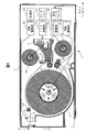
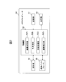
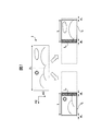
- FIG. 1 is a cross-sectional view illustrating a schematic configuration of a printer 1.
- 2 is a schematic block diagram of a host computer 50.
- FIG. It is a figure for demonstrating a density
- FIG. 1 is a cross-sectional view showing a schematic configuration of the printer 1. In FIG. 1, only the parts necessary for explanation are shown among the constituent elements provided in the printer 1, and the other constituent elements are omitted.
- the printer 1 includes, as main components, a roll paper holder 2, a head (thermal head) 3, a supply side ribbon roller 4A, a take-up side ribbon roller 4B, a cutting unit 5, a platen roller 9, a discharge roller 14, and a ribbon guide roller. 15, a grip roller 17, a pinch roller 18, and the like.
- a roll paper holder 2 includes, as main components, a roll paper holder 2, a head (thermal head) 3, a supply side ribbon roller 4A, a take-up side ribbon roller 4B, a cutting unit 5, a platen roller 9, a discharge roller 14, and a ribbon guide roller. 15, a grip roller 17, a pinch roller 18, and the like.
- a grip roller 17, a pinch roller 18, and the like is arranged in the housing 7.
- the printer 1 is a thermal transfer printer that prints an image by transferring ink applied to the ink ribbon 4 onto a roll-shaped paper 10.
- the printer 1 reciprocates the paper 10 with respect to the head 3 to sequentially transfer, for example, a plurality of yellow, magenta, and cyan colors and an overcoat from the ink ribbon 4 onto the same area of the paper 10.
- the printed paper 10 is cut by the cutting unit 5 and discharged to the outside of the printer 1 from the discharge port 6 provided on the front surface 12 of the printer 1.
- printing an image is also referred to as “printing”.
- the roll paper holder 2 holds the paper 10 wound in a roll shape.
- the material of the paper 10 is not particularly limited as long as it can be used for a thermal transfer printer.
- the roll paper holder 2 is driven in the forward direction or the reverse direction and rotates around its central axis. As the roll paper holder 2 rotates in the forward direction, the paper 10 passes between the head 3 and the platen roller 9 and is conveyed toward the discharge port 6. Further, the roll paper holder 2 rotates in the reverse direction, whereby the paper 10 is rewound onto the roll paper holder 2.
- the supply side ribbon roller 4 ⁇ / b> A and the take-up side ribbon roller 4 ⁇ / b> B hold the ink ribbon 4. These rollers are driven by an ink ribbon drive unit 24, which will be described later, and rotate around their respective central axes. By this driving, the ink ribbon 4 is supplied from the supply side ribbon roller 4A, passes between the head 3 and the platen roller 9 via the ribbon guide roller 15, and is taken up by the take-up side ribbon roller 4B.
- the ink ribbon 4 is, for example, a belt-like sheet in which yellow, magenta, and cyan ink regions and an overcoat region are repeatedly arranged in the longitudinal direction in the same order. Since there are various types of ink ribbons 4 such as those of each color ink area of 6 ⁇ 4 inches and 6 ⁇ 8 inches, the ink ribbon 4 suitable for the image size to be printed is the printer 1. Attached to.
- the head 3 is configured to be movable with respect to the platen roller 9, and is pressed by the platen roller 9 with the ink ribbon 4 and the paper 10 sandwiched therebetween during printing.
- the head 3 heats a plurality of built-in heating elements and sequentially transfers each color ink and overcoat on the ink ribbon 4 onto the same area of the paper 10, thereby printing an image on the paper. This transfer is repeated for each region of the ink ribbon 4 while the ink ribbon 4 is wound up.
- a mechanism corresponding to the type of thermal transfer printer such as a sublimation type or a thermal melting type is used.
- the grip roller 17 and the pinch roller 18 convey the paper 10 between them.
- the grip roller 17 is rotationally driven in either the direction of feeding the paper 10 (forward direction) or the direction of rewinding (reverse direction).
- the pinch roller 18 rotates following the grip roller 17.
- the pinch roller 18 is in contact with the grip roller 17 when the paper 10 is transported and holds the paper 10 with the grip roller 17, and is separated from the grip roller 17 when the paper 10 is not transported. Release 10
- the paper 10 that has passed between the head 3 and the platen roller 9 from the roll paper holder 2 is conveyed toward the discharge port 6 by the discharge roller 14 through the discharge path 13.
- the cutting unit 5 is disposed immediately before the discharge port 6 on the discharge path 13, and the sheet 10 whose front end passes through the discharge path 13 and is discharged from the discharge port 6 to the outside of the printer 1 is disposed in front of the discharge port 6. Cut at the position.
- the printer 1 also includes a control unit 20, a data memory 21, a paper drive unit 22, a head drive unit 23, an ink ribbon drive unit 24, a cutting drive unit 25, and a communication interface 26.
- the control unit 20 is composed of a microcomputer including a CPU and a memory, and controls the overall operation of the printer 1.
- the data memory 21 is a storage area for accumulating image data received from the host computer via the communication interface 26.
- the paper drive unit 22 is a motor that drives the grip roller 17 and the roll paper holder 2, and rotates each of the paper 10 in either the direction of feeding the paper 10 or the direction of rewinding.
- the head drive unit 23 drives the head 3 based on the image data to print an image on the paper 10.
- the ink ribbon drive unit 24 is a motor that drives the supply-side ribbon roller 4A and the take-up side ribbon roller 4B, and the take-up side ribbon roller 4B is in a direction to take up the ink ribbon 4, or ink is supplied to the supply-side ribbon roller 4A.
- the supply side ribbon roller 4A and the take-up side ribbon roller 4B are rotated in either direction of rewinding the ribbon 4.
- the cutting drive unit 25 is a motor that drives the cutting unit 5.
- the communication interface 26 receives, for example, a print instruction and image data to be printed from a host computer via a communication cable.
- the printer 1 performs panoramic printing of an image (for example, 6 ⁇ 16 inches) exceeding the size (for example, 6 ⁇ 8 inches) of each color ink area of the ink ribbon 4 without cutting the paper 10 halfway. This is realized by continuously printing images of the size.
- the color at the rear end of the first image and the color at the front end of the second image in the printed matter differ depending on the thermal storage temperature of the thermal head.
- an overlapping region having a width of about 10 to 20 mm is provided.
- the Y, M, and C color inks are transferred once and then the Y, M, and C color inks are transferred once more, resulting in reverse transfer phenomenon, excessive transfer phenomenon, and the like.
- the color of the printed material may be different from YMC corresponding to RGB of the original image data. Therefore, the printer 1 suppresses the occurrence of discoloration in panoramic printing by correcting such a color difference by image processing of the host computer.
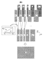
- FIG. 2 is a schematic block diagram of the host computer 50.
- the host computer 50 includes a storage unit 51 such as a magnetic disk device, a control unit 52 including a CPU, an operation unit 53 such as a keyboard and a mouse, a display unit 54 including a display device, a communication interface 55, and the like. It is a computer.
- the host computer 50 receives an image print instruction in accordance with a user operation, processes the image data to be printed by the control unit 52, and transmits the image data and the print instruction to the printer 1 via the communication interface 55.
- the host computer 50 performs color management processing on all the dots in the overlapping area of two images that are continuously printed, and the degree of overlap between the first image and the second image and the target color. From the RGB values, the gradation value RGB 1 of the first image and the gradation value RGB 2 of the second image are obtained.
- the printer 1 prints each dot in the overlapping area with an energy equivalent to RGB 1 when printing the first sheet, and prints with an energy corresponding to RGB 2 when printing the second sheet. Express the color to be.
- the printer 1 also superimposes two images while gradually decreasing or increasing the print density in an overlapping region of two consecutive images so as to make the region inconspicuous.
- the storage unit 51 stores a density correction table for the first image and a density correction table for the second image.
- the storage unit 51 stores these density correction tables for each color of yellow Y, magenta M, and cyan C.
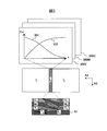
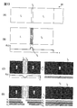
- FIG. 3 is a diagram for explaining the density correction table.
- Reference numerals 300Y, 300M, and 300C in FIG. 3 are density correction tables for yellow Y, magenta M, and cyan C, respectively.
- Arrows A2 and A3 correspond to the sub-scanning direction and main-scanning direction at the time of transfer, respectively, and this is the same in each drawing described below.
- a curve denoted by reference numeral 301 is a density correction table at the rear end of the first partial image I1, and indicates that the density decreases toward the second image side.
- a curve denoted by reference numeral 302 is a density correction table at the tip of the second partial image I2, and indicates that the density increases toward the opposite side to the first image. The same applies to magenta M and cyan C.
- FIG. 3 also shows a cross section of each YMC ink layer transferred in the overlapping region IO .
- symbol E 1 indicates the rear end of the first partial image I 1
- symbol T 2 indicates the leading end of the second partial image I 2 .
- the joint of the ink layers in the overlapping region I O is yellow Y, magenta M, and cyan C (between Y 1 , M 1, and C 1 for the partial image I 1). coincides with Y 2, between M 2 and C 2) for the partial image I 2. Therefore, the density correction tables 300Y, 300M, and 300C are created for the same range in the sub-scanning direction.
- FIG. 4 (B) is a density correction table for partial image I 2 of the second sheet of yellow Y.
- an overlap region is formed by n lines L 1 to L n along the main scanning direction (direction of arrow A3 in FIG. 3) at the time of transfer, and the gradation value of Y is represented by 0 to 255.
- Each density correction table stores a correction coefficient for each gradation value (a correction coefficient for print density at each position on the overlapping area) for each position x in the sub-scanning direction.
- the storage unit 51 stores the density correction tables of FIGS. 4A and 4B for yellow Y, and stores the same density correction tables for magenta M and cyan C.
- the density correction table prints a single-color solid image twice, according to a certain correction coefficient of an initial value, and measures the presence or absence of a difference in density between the overlap area of the printed material and the other areas. For example, it is created experimentally by repeating the procedure of adjusting the magnitude of the correction coefficient until the difference in density is eliminated.
- the density correction tables for yellow Y, magenta M, and cyan C are created using solid images of Y, M, and C, respectively.
- Y, M, and C monochrome images for example, gray images with different densities such as light, medium, and dark may be used to create the density correction table.
- the storage unit 51 may store the same density correction table for RGB instead of YMC.
- each color ink of yellow Y, magenta M, and cyan C is transferred twice, so that the color development characteristics may change depending on the mixing ratio of YMC. Therefore, the change in the color development characteristic due to the color ratio may be corrected by further adjusting the value of the density correction table created from the solid image as necessary.
- FIG. 5 is a diagram for explaining the adjustment of the density correction table according to the color ratio.
- Reference numeral 500 indicates the density correction tables 501 and 502 for yellow Y, magenta M, and cyan C for the first and second images. These are the same as those indicated by reference numerals 301 and 302 in FIG.
- Reference numeral 503 indicates a correspondence relationship between the position x in the sub-scanning direction in the overlapping region, the YMC mixing ratio (color ratio) r, and the density adjustment value h.
- Reference numeral 500 ′ indicates density correction tables 501 ′ and 502 ′ for yellow Y, magenta M, and cyan C for the first and second images after adjustment using the correspondence relationship 503.
- the density correction tables 501 ′ and 502 ′ are created by reflecting the density adjustment value h at each position x in the sub-scanning direction in the YMC density correction tables 501 and 502 at a certain ratio.
- the storage unit 51 may store the density correction tables 501 'and 502' adjusted in this way for each of the YMCs instead of the density correction tables 300Y, 300M, and 300C of FIG.
- the storage unit 51 may store the correspondence relationship 503 and the reflection degree (duty ratio) of the density adjustment value h at each position x in the sub-scanning direction.
- the control unit 52 may adjust the values of the density correction tables 300Y, 300M, and 300C with reference to the information as necessary.
- the storage unit 51 stores a color conversion table for converting the YMC gradation value YMC into another gradation value YMC ′ for a plurality of positions in the overlapping region IO in different sub-scanning directions.
- This color conversion table is for canceling the color change that may occur on the printed material in the overlap region when two images are transferred in a superimposed manner according to the above-described density correction table at the target position in the sub-scanning direction.
- each color conversion table includes the value of the gradation value YMC to be transmitted to the printer 1 so that the color corresponding to the target gradation value YMC is printed for each mixing ratio of YMC.
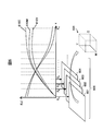
- FIG. 6 is a diagram for explaining the color conversion table.
- the horizontal axis x of the graph shown in the upper side of FIG. 6 is the position in the sub-scanning direction in the overlapping region IO
- the vertical axis f (x) is the gradation value of yellow Y, magenta M or cyan C at the position x.
- Reference numerals 610Y, 610M, and 610C are the same density correction tables as shown by reference numerals 300Y, 300M, and 300C in FIG. 3 for yellow Y, magenta M, and cyan C, respectively.
- a plurality of positions in the sub-scanning direction in the overlap region I O X 1, X 2, X 3, ⁇ , the X m, and the gradation value YMC before conversion, gradation value YMC after conversion are stored as color conversion tables 601, 602, 603, 604,.
- These color conversion tables are an example of a color conversion coefficient group. For example, if each gradation value of Y, M, and C is represented by a value of 0 to 255, each color conversion table is a three-dimensional table having 256 ⁇ 256 ⁇ 256 components.
- a color conversion table group 600 which is a set of color conversion tables, is unique to the printer 1 regardless of the image to be printed.
- the storage unit 51 stores the color conversion table not only for all the lines L 1 to L n whose positions in the sub-scanning direction are different from each other in the overlapping region, but only for some of them.
- the color conversion table group 600 includes m (m ⁇ n) color conversion tables corresponding to positions X 1 to X m in the sub-scanning direction. Further, the positions X 1 to X m where the color conversion table is created may not be equally spaced.
- the position X 1 to the position X 1 to be dense so that the correction coefficients of the density correction tables 610Y, 610M, and 610C are dense in a range where the correction coefficients are largely changed, and are sparse in the range where the correction coefficients of the density correction tables 610Y, 610M, and 610C are not changed so much.
- the X m may be selected.
- the color conversion tables in the lines other than the positions X 1 to X m are supplemented by linear interpolation using the color conversion tables at other positions.
- the color conversion table group 600 creates a plurality of color patches having different YMC mixing ratios, prints two color patches for each color according to the density correction table, and is selected in the sub-scanning direction. It is created by measuring the color of the printed material at each of the positions X 1 to X m and obtaining the corresponding relationship YMC ⁇ YMC ′ of each color. That is, each color conversion table corresponds to an ICC profile in color management processing.
- the storage unit 51 stores a correspondence between RGB values (RGB ⁇ RGB ′) or a correspondence between RGB values and YMC values (RGB ⁇ YMC ′) instead of the color conversion table for YMC. May be. Or the memory
- the control unit 52 includes an image dividing unit 52A, a color conversion unit 52B, a composition processing unit 52C, and a density correction unit 52D as functional blocks for processing image data to be printed.
- the control unit 52 converts RGB of the image data to be printed into YMC, converts the YMC in the overlapping area into YMC ′ using the color conversion table, and uses the density correction table.
- YMC ′ is converted into YMC 1 ′ of the first image and YMC 2 ′ of the second image, and these are transmitted to the printer 1.
- the function of each functional block of the control part 52 is demonstrated in order.
- the image dividing unit 52A divides the color image data to be printed into image data of two partial images including overlapping areas that overlap each other. At that time, as shown in FIG. 3, the image dividing unit 52A does not shift the end of each partial image for each color of the plurality of colors of ink (YMC) transferred to the paper, and the two parts for each color of YMC. Match the edges of the image.
- each partial image is composed of a set of a Y image, an M image, and a C image transferred on top of each other, so that the image dividing unit 52A has the same partial image as shown in the lower side of FIG.
- the color image data to be printed is divided into image data of two sets of partial images so that the ends of the Y image, M image, and C image match.
- FIG. 7 is a diagram for explaining the function of the image dividing unit 52A.
- the width in the sub-scanning direction (arrow A2 direction) of the 6 ⁇ 16 inch image I to be printed is 2L.
- the image dividing unit 52A discards the portion of the width dL from the front end of the image I in the sub-scanning direction, and 1 from the region of the width L along the sub-scanning direction from there. and the partial image I 1 of the sheet.
- the image dividing unit 52A discarded portion of the width dL from the rear end of the image I, a region of width L along the sub-scanning direction therefrom and the second sheet of the partial image I 2.
- a region having a width of dL ⁇ 2 indicated by a diagonal line in the center of the image I becomes a common overlapping region I O in the two partial images I 1 and I 2 .
- the color conversion unit 52B converts color values in the overlapping area created by the image dividing unit 52A in the image data to be printed. For example, the color conversion unit 52B converts the YMC of each dot in the overlapping area into YMC ′ using the color conversion table group 600. However, when the color conversion table group is created with RGB or Lab values, the color conversion unit 52B performs RGB value conversion or Lab value conversion. In particular, when the storage unit 51 stores color conversion tables for all the lines L 1 to L n along the main scanning direction in the overlapping region IO , the color conversion unit 52B The color value of each dot is converted using the corresponding color conversion table.
- the storage unit 51 may store a color conversion table only for some lines along the main scanning direction. Therefore, the color conversion unit 52B divides the overlapping area into a plurality of partial areas along the main scanning direction when transferring the image, and sets a common color conversion table in the partial area for each of the plurality of partial areas. It is preferable to use it to convert the color value of the image data. In this case, for each partial area, the color conversion unit 52B converts the color value of the image data in two ways using the color conversion table of the partial area and the color conversion table of the partial area adjacent to the partial area.
- FIG. 8 is a diagram for explaining the function of the color conversion unit 52B.
- the color conversion unit 52B overlaps the two partial images generated by the image division unit 52A with the positions X 1 to X m in the sub-scanning direction in which the color conversion table is stored in the storage unit 51 as a boundary.
- I O is divided into partial regions O 1 to O m ⁇ 1 along the main scanning direction.
- the color conversion unit 52B configures the partial regions O 1 to O m ⁇ 1 so that the end portions of the Y image, the M image, and the C image coincide with each other.
- the position X 1 and X m is an end portion of the overlapping region I O respectively.
- the color conversion unit 52B converts the partial area O 1 into the partial areas O 1 ′ and O 1 ′′ using the color conversion tables 601 and 602 at the positions X 1 and X 2 , respectively, and the positions X 2 , X
- the partial area O 2 is converted into partial areas O 2 ′ and O 2 ′′ using the color conversion tables 602 and 603 in FIG. 3 , respectively, and the partial areas O 1 ′ to O m ⁇ 1 ′ and the partial areas are converted in the same manner.
- Image data of O 1 ′′ to O m ⁇ 1 ′′ is created.
- the color conversion unit 52B converts the image data in each partial area using the color conversion table of the partial area, and also converts the image data using the color conversion table of the partial area adjacent to the partial area. Create image data.
- the composition processing unit 52C obtains the converted color values in the entire overlapping region by combining the color values converted in two ways by the color conversion unit 52B for each of the plurality of partial regions. At that time, the composition processing unit 52C synthesizes individual color values by weighting and adding the corresponding two color values of the image data for each partial region.
- FIG. 9 is a diagram for explaining the function of the composition processing unit 52C.
- the combining processing unit 52C combines the partial areas O 1 ′, O 1 ′′ with the partial areas O 1 ′′ ′′, combines the partial areas O 2 ′, O 2 ′′ with the partial areas O 2 ′′ ′′, In the same manner, image data of the partial areas O 1 '''to O m-1 ''' are created.
- the composition processing unit 52C increases the color value ratio of the partial region O 1 ′ as it approaches the left end position X 1, and moves to the right end position X 2 .
- the composition processing unit 52C joins the partial areas O 1 ′′ ′′ to O m ⁇ 1 ′ ′′ to create image data of the converted overlapping area I O ′.
- the color value of the line L k of positions X 2 and the line L 1 position X 1 is Are converted by the color conversion tables 601 and 602 at the positions X 1 and X 2 , respectively, and the color values in the lines L 2 to L k ⁇ 1 are generated by linear interpolation using the color conversion tables 601 and 602. Converted by As a result, even when the storage unit 51 does not store the color conversion table for all the lines L 1 to L n along the main scanning direction in the overlapping area IO , when two images are transferred in an overlapping manner.
- the composition processing unit 52C is not necessary.
- the density correction unit 52D uses the density correction table stored in the storage unit 51 to adjust the color value in the overlapping area after being converted by the color conversion unit 52B and synthesized by the synthesis processing unit 52C. That is, the density correction unit 52D corrects the YMC gradation values of the overlapped area that has been converted and synthesized using the density correction table for the first image and the density correction table for the second image. As a result, the image data of the overlapping area for the first image and the overlapping area for the second image is created. Then, the density correction unit 52D reflects the overlap area in each partial image, and creates image data for the first sheet and image data for the second sheet.
- FIG. 10 is a diagram for explaining the function of the density correction unit 52D.
- the density correction unit 52D corrects the YMC values of the image data of the overlapping region I O ′ synthesized by the synthesis processing unit 52C using the density correction tables 300Y, 300M, and 300C, respectively.
- the density correction unit 52D applies the table in FIG. 4A (the curve indicated by reference numeral 301 in FIG. 3) in the overlapping region I O1 ′′ of the first partial image.
- a Y value of the image data is created, and the Y value of the image data in the overlapping area I O2 ′′ of the second partial image is applied by applying the table of FIG. 4B (the curve of reference numeral 302 in FIG. 3).
- the density correction unit 52D creates the gradation values of the overlapping areas for the two partial images.
- the YMC value created in this way becomes image data in the overlapping area I O1 ′′ of the first partial image and image data in the overlapping area I O2 ′′ of the second partial image.
- the density correction unit 52D changes the overlapping area I O in the first partial image I 1 to the overlapping area I O1 ′′, and changes the overlapping area I O in the second partial image I 2 to the overlapping area I O2. ”To create image data of the final two partial images I 1 ′ and I 2 ′.
- the control unit 52 transmits the image data of the two partial images I 1 ′ and I 2 ′ created by the density correction unit 52D to the printer 1 via the communication interface 55.
- the printer 1 sequentially transfers the partial images according to the image data of the two partial images I 1 ′ and I 2 ′ so that the overlapping areas overlap, and forms a color image I to be printed on the paper. To do. Thereby, the printer 1 realizes panoramic printing.
- the host computer 50 When the printer 1 prints an image smaller than the size of each color ink area of the ink ribbon (that is, panorama printing is not performed), the host computer 50 does not perform the above-described image processing, and RGB of the image data to be printed.
- the value (YMC value) is transmitted to the printer 1 as it is.
- FIG. 11 is a diagram illustrating an example of a processing flow of image data by the control unit 52.
- the illustrated flow is executed by the CPU in the control unit 52 in accordance with a program stored in advance in the ROM in the control unit 52 of the host computer 50.
- a program stored in advance in the ROM in the control unit 52 of the host computer 50 it is assumed that printing of a 6 ⁇ 16 inch image is instructed in a state where an ink ribbon having each color ink region of 6 ⁇ 8 inches is attached to the printer 1.
- the image dividing unit 52A divides the color image data to be printed into image data of two partial images including overlapping regions that overlap each other (S1).
- the color conversion unit 52B divides the overlapping region created in S1 into a plurality of partial regions with the positions X 1 to X m in the sub-scanning direction in which the color conversion table is stored in the storage unit 51 as a boundary.
- the color value in each partial area is converted in two ways (S2).
- the color conversion unit 52B converts the color value of the image data of the target partial area in two ways using the color conversion table of one partial area and the color conversion table of the partial area adjacent to the partial area. To do.
- the composition processing unit 52C synthesizes the color values of the partial areas converted in two ways in S2, and acquires the converted color values of the entire overlapping area (S3). Further, the density correction unit 52D uses the density correction table stored in the storage unit 51 to adjust the print density in the overlapped area obtained in S3 and convert the image data of the two partial images. Create (S4). Finally, the control unit 52 transmits the image data of the two partial images created in S4 to the printer 1 (S5). Thus, the processing flow of the image data by the control unit 52 ends.
- the color conversion table for converting the color value of the image data so as to cancel the discoloration that may occur in the overlapping region of the images when two images are continuously transferred is previously stored. Create it.
- the host computer 50 corrects the color value of the image data to be printed using the color conversion table, thereby suppressing the occurrence of discoloration in the overlapping region of the images.
- the joints of the ink layers when transferring two images successively are matched with each other color of YMC. For this reason, the size of the overlapping area of the images can be minimized, and each color ink area of the ink ribbon can be effectively used.
- the image processing by the image dividing unit 52A, the color conversion unit 52B, the composition processing unit 52C, and the density correction unit 52D of the host computer 50 may be performed by the control unit 20 of the printer 1.
- the density correction tables 300Y, 300M, and 300C and the color conversion table group 600 necessary for the image processing are stored in advance in a memory built in the printer 1.
Abstract
In the present invention, when printing an image of a size larger than that which can be transferred in one operation by sequentially transferring a plurality of partial images and joining the same, overlapping regions of the respective partial images are made to be as narrow as possible and the occurrence of color changes in the overlapping regions is suppressed. Color image data to be printed is divided into image data of two partial images that each have an end section which includes an overlapping region which overlaps the other end section and which conforms to the other end section with respect to colors of ink to be transferred to paper. Color values in the overlapping regions of the color image data are converted using a color conversion coefficient group created beforehand for positions on the overlapping regions so as to cancel changes in the colors in the overlapping regions due to the two partial images being transferred in an overlapping manner. The image data of the two partial images is corrected by adjusting the color values in the converted overlapping regions using correction coefficients for the printing density at each position on the overlapping regions. In accordance with the image data of the corrected two partial images, the two partial images are sequentially transferred so that the respective overlapping regions overlap each other, thereby forming a color image.
Description
本発明は、熱転写プリンタおよびその制御方法に関する。
The present invention relates to a thermal transfer printer and a control method thereof.
図12は、熱転写プリンタによる通常の印画について説明するための図である。カラー画像を印刷可能な熱転写プリンタは、例えば、イエローY、マゼンタMおよびシアンCの各色インク領域ならびにオーバーコートOPの領域が同じ順序で長手方向に繰り返し配置されたインクリボン4を矢印A1方向に搬送しながら、その各色インクなどをロール状の用紙10の上に順次転写して、用紙10に画像Iを印刷(印画)する。通常の印画では、熱転写プリンタは、イエローY、マゼンタM、シアンCおよびオーバーコートOPを順次転写した後に、用紙10を矢印A2方向に搬送してその先端を切断し、さらに用紙10を矢印A2方向に搬送して画像Iの後端を切断することで、印画物を排出する。
FIG. 12 is a diagram for explaining normal printing by a thermal transfer printer. A thermal transfer printer capable of printing a color image, for example, transports an ink ribbon 4 in which the yellow Y, magenta M, and cyan C color ink areas and the overcoat OP area are repeatedly arranged in the same order in the longitudinal direction in the direction of arrow A1. Meanwhile, the respective color inks and the like are sequentially transferred onto the roll-shaped paper 10, and the image I is printed (printed) on the paper 10. In normal printing, the thermal transfer printer sequentially transfers yellow Y, magenta M, cyan C, and overcoat OP, then transports the paper 10 in the direction of arrow A2, cuts the leading edge, and further moves the paper 10 in the direction of arrow A2. And the printed image is discharged by cutting the rear end of the image I.
こうしたプリンタでは、印刷可能な画像サイズがインクリボン4の各色インク領域のサイズによって制限されるが、1つの画像を印刷した後に用紙10を切断せず連続して次の画像を印刷することで、インクリボン4の各色インク領域よりも大きいサイズの印刷を実現する技術がある。このような印刷のことを、以下では「パノラマ印刷」という。
In such a printer, the printable image size is limited by the size of each color ink region of the ink ribbon 4, but after printing one image, the next image is printed continuously without cutting the paper 10. There is a technique for realizing printing of a size larger than each color ink area of the ink ribbon 4. Such printing is hereinafter referred to as “panoramic printing”.
図13(A)~図13(D)は、従来のパノラマ印刷の方法について説明するための図である。用紙10を切断せず単に複数の画像の印刷を連続して行うだけでは、図13(A)に示すように、用紙10上における1枚目の画像I1と2枚目の画像I2との間に余白I3ができてしまう。この余白I3をなくすために、図13(B)に示すように、1枚目の画像I1と2枚目の画像I2の端部同士を部分的に重ね合わせて印刷すると、画像の重なり領域IOの印画濃度がそれ以外の領域の印画濃度よりも高くなり、重なり領域IOが目立ってしまう。なお、図13(B)および図13(C)において、xは用紙10の長手方向(図12における矢印A2方向)の位置を示し、f(x)は位置xにおける印画濃度を示す。
13A to 13D are diagrams for explaining a conventional panoramic printing method. By simply printing a plurality of images continuously without cutting the paper 10, as shown in FIG. 13A, the first image I 1 and the second image I 2 on the paper 10 she can margin I 3 between. To eliminate this margin I 3, as shown in FIG. 13 (B), the image I 1 of the first sheet and the second sheet ends of the image I 2 of not partially overlapped to print an image of printing density of the overlapping regions I O is higher than the print density of the other regions, resulting in conspicuous overlap region I O. 13B and 13C, x indicates the position in the longitudinal direction of the paper 10 (the direction of arrow A2 in FIG. 12), and f (x) indicates the print density at the position x.
そこで、例えば特許文献1,2では、図13(C)に示すように、2枚の画像の重なり領域IOにおいて、1枚目の画像I1の印画濃度を終端側(2枚目側)に向けて徐々に低くし、2枚目の画像I2の印画濃度を先端側(1枚目側)から徐々に高くすることで、重なり領域IOの印画濃度を調整する方法が提案されている。また、特許文献3では、図13(D)に示すように、2枚の画像I1,I2のつなぎ目をY,M,Cの色ごとに副走査転写方向にずらし、かつ重なり部分の階調データを副走査転写方向のライン毎に予め設定された補正係数に基づき補正することにより画像のつなぎ目を目立たなくする方法が提案されている。
Therefore, for example, in Patent Documents 1 and 2, as shown in FIG. 13C, the print density of the first image I1 is set to the end side (second sheet side) in the overlapping area IO of the two images. A method has been proposed in which the print density of the overlapping area I O is adjusted by gradually decreasing the print density toward the image area and gradually increasing the print density of the second image I 2 from the front end side (first image side). Yes. Further, in Patent Document 3, as shown in FIG. 13D, the joint of the two images I 1 and I 2 is shifted in the sub-scanning transfer direction for each of the colors Y, M, and C, and the level of the overlapping portion is set. A method has been proposed in which tone data is corrected based on a correction coefficient set in advance for each line in the sub-scanning transfer direction so that the joint of the image is inconspicuous.
しかしながら、2枚の画像を重ねて印刷する場合には、先に転写されたインクが後の転写時の印加エネルギーによりインクリボンに移ってしまい転写濃度が低下する逆転写現象や、先の転写により用紙のインク受容層が変質するために後から転写されるインク色の濃度が増加する過剰転写現象が発生し得る。このため、単に2枚の画像の重なり領域で1枚目の画像後端の印画濃度を徐々に低下させ、2枚目の画像先端の印画濃度を徐々に上昇させるだけでは、重なり領域の発色が重なり領域以外の発色とは異なることがよくあり、重なり領域において目的の色を表現することは難しい。また、Y,M,Cの色ごとに2枚の画像のつなぎ目をずらす場合には、そうしない場合と比べて、隣接する画像間で印画濃度を調整する領域の副走査方向における幅が広くなるため、インクリボンの各色インク領域を有効に利用できないという不都合がある。
However, when two images are printed in an overlapping manner, the previously transferred ink is transferred to the ink ribbon due to the energy applied during the subsequent transfer, resulting in a reverse transfer phenomenon in which the transfer density decreases, or due to the previous transfer. Since the ink receiving layer of the paper is altered, an overtransfer phenomenon in which the density of ink color transferred later increases may occur. For this reason, simply by gradually decreasing the print density at the trailing edge of the first image in the overlapping area of the two images and gradually increasing the printing density at the leading edge of the second image, the color of the overlapping area is developed. It is often different from the color development other than the overlapping area, and it is difficult to express the target color in the overlapping area. Also, when shifting the joint between two images for each of the colors Y, M, and C, the width in the sub-scanning direction of the area for adjusting the print density between adjacent images is wider than when the joint is not performed. Therefore, there is an inconvenience that each color ink area of the ink ribbon cannot be used effectively.
そこで、本発明は、複数の部分画像を順次転写して繋ぎ合わせることで一度に転写可能な大きさよりも大きい画像を印画する際に、部分画像同士の重なり領域を極力狭くしつつ重なり領域における変色の発生を抑制する熱転写プリンタおよびその制御方法を提供することを目的とする。
In view of this, the present invention, when printing an image larger than the size that can be transferred at once by sequentially transferring and joining a plurality of partial images, discoloration in the overlapping region while minimizing the overlapping region between the partial images. It is an object of the present invention to provide a thermal transfer printer that suppresses the occurrence of ink and a control method thereof.
印画対象のカラー画像データを、互いに重複する重なり領域を含みかつ用紙に転写される複数色のインクのそれぞれについて一致した端部を有する2つの部分画像の画像データに分割するステップと、2つの部分画像が重ねて転写されることによる重なり領域での色の変化を打ち消すように重なり領域上の異なる複数の位置について予め作成された色変換係数群を用いて、カラー画像データの重なり領域における色値を変換するステップと、重なり領域上の各位置における印画濃度の補正係数を用いて変換後の重なり領域における色値を調整することにより2つの部分画像の画像データを補正するステップと、補正された2つの部分画像の画像データに従い重なり領域が重なるように2つの部分画像を順次転写して印画対象のカラー画像を形成するステップとを有することを特徴とする熱転写プリンタの制御方法が提供される。
Dividing the color image data to be printed into image data of two partial images that include overlapping areas that overlap each other and that have matching end portions for each of a plurality of color inks to be transferred to the paper; Color values in the overlapping area of color image data using color conversion coefficient groups created in advance at different positions on the overlapping area so as to cancel the color change in the overlapping area due to the image being transferred in an overlapping manner A step of correcting the image data of the two partial images by adjusting the color value in the overlapped area after conversion using the correction coefficient of the print density at each position on the overlapped area, and the corrected According to the image data of the two partial images, the two partial images are sequentially transferred so that the overlapping areas overlap, and the color image to be printed is obtained. The method of thermal transfer printer, characterized by a step of forming is provided.
上記の変換するステップでは、画像を転写するときの主走査方向に沿って重なり領域を複数の部分領域に分割し、複数の部分領域のそれぞれについて、その部分領域内で共通の色変換係数群を用いてカラー画像データの色値を変換することが好ましい。
In the converting step, the overlapping area is divided into a plurality of partial areas along the main scanning direction when the image is transferred, and for each of the plurality of partial areas, a common color conversion coefficient group is set in the partial area. It is preferable to use to convert the color value of the color image data.
上記の変換するステップでは、複数の部分領域のそれぞれについて、その部分領域の色変換係数群とその部分領域に隣接する部分領域の色変換係数群とを用いてカラー画像データの色値を2通りに変換し、複数の部分領域のそれぞれについて2通りに変換された色値を合成することにより、重なり領域の全体における変換後の色値を取得するステップをさらに有することが好ましい。
In the converting step, for each of the plurality of partial areas, two color values of the color image data are obtained using the color conversion coefficient group of the partial area and the color conversion coefficient group of the partial area adjacent to the partial area. Preferably, the method further includes a step of acquiring the converted color value in the entire overlapping region by combining the color values converted into two types for each of the plurality of partial regions.
また、印画対象のカラー画像データを、互いに重複する重なり領域を含みかつ用紙に転写される複数色のインクのそれぞれについて一致した端部を有する2つの部分画像の画像データに分割する画像分割部と、2つの部分画像が重ねて転写されることによる重なり領域での色の変化を打ち消すように重なり領域上の異なる複数の位置について予め作成された色変換係数群を用いて、カラー画像データの重なり領域における色値を変換する色変換部と、重なり領域上の各位置における印画濃度の補正係数を用いて変換後の重なり領域における色値を調整することにより2つの部分画像の画像データを補正する濃度補正部と、補正された2つの部分画像の画像データに従い重なり領域が重なるように2つの部分画像を順次転写して印画対象のカラー画像を形成する印画部とを有することを特徴とする熱転写プリンタが提供される。
An image dividing unit that divides the color image data to be printed into image data of two partial images that include overlapping regions that overlap each other and that have matching end portions for each of a plurality of colors of ink that are transferred to paper; Overlapping color image data using color conversion coefficient groups created in advance at different positions on the overlapping area so as to cancel the color change in the overlapping area due to the transfer of two partial images superimposed The image data of the two partial images is corrected by adjusting the color values in the overlapped area after conversion using a color conversion unit that converts color values in the area and the print density correction coefficient at each position on the overlapped area. In accordance with the density correction unit and the corrected image data of the two partial images, the two partial images are sequentially transferred so that the overlapping area overlaps, and the print target cover is thus transferred. Thermal transfer printer is provided, characterized in that it comprises a printing unit for forming an over images.
上記の熱転写プリンタおよびその制御方法によれば、複数の部分画像を順次転写して繋ぎ合わせることで一度に転写可能な大きさよりも大きい画像を印画する際に、部分画像同士の重なり領域を極力狭くしつつ重なり領域における変色の発生を抑制することが可能になる。
According to the above thermal transfer printer and its control method, when an image larger than a size that can be transferred at once is printed by sequentially transferring and joining a plurality of partial images, the overlapping area between the partial images is made as narrow as possible. However, the occurrence of discoloration in the overlapping region can be suppressed.
以下、図面を参照しつつ、熱転写プリンタおよびその制御方法について説明する。ただし、本発明は図面または以下に記載される実施形態には限定されないことを理解されたい。
Hereinafter, the thermal transfer printer and its control method will be described with reference to the drawings. However, it should be understood that the present invention is not limited to the drawings or the embodiments described below.
図1は、プリンタ1の概略構成を示す断面図である。図1では、プリンタ1が備える各構成要素の内で、説明のために必要な部分のみを示し、その他の構成要素については省略している。
FIG. 1 is a cross-sectional view showing a schematic configuration of the printer 1. In FIG. 1, only the parts necessary for explanation are shown among the constituent elements provided in the printer 1, and the other constituent elements are omitted.
プリンタ1は、主な構成要素として、ロール紙ホルダ2、ヘッド(サーマルヘッド)3、供給側リボンローラ4A、巻取側リボンローラ4B、切断部5、プラテンローラ9、排出ローラ14、リボンガイドローラ15、グリップローラ17、ピンチローラ18などを有する。これらの各構成要素は、筐体7の中に配置されている。
The printer 1 includes, as main components, a roll paper holder 2, a head (thermal head) 3, a supply side ribbon roller 4A, a take-up side ribbon roller 4B, a cutting unit 5, a platen roller 9, a discharge roller 14, and a ribbon guide roller. 15, a grip roller 17, a pinch roller 18, and the like. Each of these components is arranged in the housing 7.
プリンタ1は、インクリボン4に塗布されたインクをロール状の用紙10に転写して画像を印刷する熱転写プリンタである。プリンタ1は、ヘッド3に対して用紙10を往復動させることにより、用紙10の同一領域上に、例えばイエロー、マゼンタおよびシアンの複数色およびオーバーコートをインクリボン4から順次転写する。印刷された用紙10は、切断部5により切断されて、プリンタ1の前面12に設けられた排出口6からプリンタ1の外部に排出される。なお、以下では、画像を印刷(プリント)することを「印画」ともいう。
The printer 1 is a thermal transfer printer that prints an image by transferring ink applied to the ink ribbon 4 onto a roll-shaped paper 10. The printer 1 reciprocates the paper 10 with respect to the head 3 to sequentially transfer, for example, a plurality of yellow, magenta, and cyan colors and an overcoat from the ink ribbon 4 onto the same area of the paper 10. The printed paper 10 is cut by the cutting unit 5 and discharged to the outside of the printer 1 from the discharge port 6 provided on the front surface 12 of the printer 1. Hereinafter, printing an image is also referred to as “printing”.
ロール紙ホルダ2は、ロール状に巻かれた用紙10を保持する。用紙10の材質は、熱転写プリンタに使用可能なものであれば特に限定されない。ロール紙ホルダ2は、正方向または逆方向に駆動されて、その中心軸の周りに回転する。ロール紙ホルダ2が正方向に回転することにより、用紙10は、ヘッド3とプラテンローラ9の間を通過して、排出口6に向けて搬送される。また、ロール紙ホルダ2が逆方向に回転することにより、用紙10はロール紙ホルダ2に巻き戻される。
The roll paper holder 2 holds the paper 10 wound in a roll shape. The material of the paper 10 is not particularly limited as long as it can be used for a thermal transfer printer. The roll paper holder 2 is driven in the forward direction or the reverse direction and rotates around its central axis. As the roll paper holder 2 rotates in the forward direction, the paper 10 passes between the head 3 and the platen roller 9 and is conveyed toward the discharge port 6. Further, the roll paper holder 2 rotates in the reverse direction, whereby the paper 10 is rewound onto the roll paper holder 2.
供給側リボンローラ4Aと巻取側リボンローラ4Bは、インクリボン4を保持する。これらのローラは、後述するインクリボン駆動部24によって駆動され、それぞれの中心軸の周りに回転する。この駆動により、インクリボン4は、供給側リボンローラ4Aから供給され、リボンガイドローラ15を介してヘッド3とプラテンローラ9の間を通過して、巻取側リボンローラ4Bに巻き取られる。
The supply side ribbon roller 4 </ b> A and the take-up side ribbon roller 4 </ b> B hold the ink ribbon 4. These rollers are driven by an ink ribbon drive unit 24, which will be described later, and rotate around their respective central axes. By this driving, the ink ribbon 4 is supplied from the supply side ribbon roller 4A, passes between the head 3 and the platen roller 9 via the ribbon guide roller 15, and is taken up by the take-up side ribbon roller 4B.
インクリボン4は、例えば、イエロー、マゼンタおよびシアンの各色インク領域ならびにオーバーコートの領域が同じ順序で長手方向に繰り返し配置された帯状のシートである。インクリボン4には、各色インク領域のサイズが6×4インチのものや6×8インチのものなど、様々な種類のものがあるため、印画対象の画像サイズに合ったインクリボン4がプリンタ1に取り付けられる。
The ink ribbon 4 is, for example, a belt-like sheet in which yellow, magenta, and cyan ink regions and an overcoat region are repeatedly arranged in the longitudinal direction in the same order. Since there are various types of ink ribbons 4 such as those of each color ink area of 6 × 4 inches and 6 × 8 inches, the ink ribbon 4 suitable for the image size to be printed is the printer 1. Attached to.
ヘッド3は、プラテンローラ9に対して移動可能に構成され、印画時には、インクリボン4と用紙10を間に挟んだ状態でプラテンローラ9に押圧される。ヘッド3は、内蔵された複数の発熱体を発熱させて、インクリボン4上の各色インクとオーバーコートを用紙10の同一領域上に順次転写することにより、用紙に画像を印刷する。この転写は、インクリボン4が巻き取られる間に、インクリボン4の領域ごとに繰り返される。ヘッド3には、例えば昇華型、熱溶融型などの熱転写プリンタの種類に応じた機構が用いられる。
The head 3 is configured to be movable with respect to the platen roller 9, and is pressed by the platen roller 9 with the ink ribbon 4 and the paper 10 sandwiched therebetween during printing. The head 3 heats a plurality of built-in heating elements and sequentially transfers each color ink and overcoat on the ink ribbon 4 onto the same area of the paper 10, thereby printing an image on the paper. This transfer is repeated for each region of the ink ribbon 4 while the ink ribbon 4 is wound up. For the head 3, for example, a mechanism corresponding to the type of thermal transfer printer such as a sublimation type or a thermal melting type is used.
グリップローラ17とピンチローラ18は、用紙10を挟んで搬送する。グリップローラ17は、用紙10を送り出す方向(正方向)か、または巻き戻す方向(逆方向)のいずれかに回転駆動される。ピンチローラ18は、グリップローラ17に従動して回転する。また、ピンチローラ18は、用紙10の搬送時には、グリップローラ17に当接してグリップローラ17との間で用紙10を保持し、用紙10の搬送時以外には、グリップローラ17から離間して用紙10を解放する。
The grip roller 17 and the pinch roller 18 convey the paper 10 between them. The grip roller 17 is rotationally driven in either the direction of feeding the paper 10 (forward direction) or the direction of rewinding (reverse direction). The pinch roller 18 rotates following the grip roller 17. The pinch roller 18 is in contact with the grip roller 17 when the paper 10 is transported and holds the paper 10 with the grip roller 17, and is separated from the grip roller 17 when the paper 10 is not transported. Release 10
ロール紙ホルダ2からヘッド3とプラテンローラ9の間を通過した用紙10は、排出経路13を通って、排出ローラ14により排出口6に向けて搬送される。切断部5は、排出経路13上における排出口6の直前に配置されており、先端が排出経路13を通過し排出口6からプリンタ1の外部に排出された用紙10を、排出口6の手前の位置で切断する。
The paper 10 that has passed between the head 3 and the platen roller 9 from the roll paper holder 2 is conveyed toward the discharge port 6 by the discharge roller 14 through the discharge path 13. The cutting unit 5 is disposed immediately before the discharge port 6 on the discharge path 13, and the sheet 10 whose front end passes through the discharge path 13 and is discharged from the discharge port 6 to the outside of the printer 1 is disposed in front of the discharge port 6. Cut at the position.
また、プリンタ1は、制御部20、データメモリ21、用紙駆動部22、ヘッド駆動部23、インクリボン駆動部24、切断駆動部25および通信インタフェース26を備える。
The printer 1 also includes a control unit 20, a data memory 21, a paper drive unit 22, a head drive unit 23, an ink ribbon drive unit 24, a cutting drive unit 25, and a communication interface 26.
制御部20は、CPUやメモリなどを含むマイクロコンピュータで構成され、プリンタ1の全体の動作を制御する。データメモリ21は、通信インタフェース26を介してホストコンピュータから受信した画像データを蓄積する記憶領域である。用紙駆動部22は、グリップローラ17とロール紙ホルダ2を駆動するモータであり、用紙10を送り出す方向か、または巻き戻す方向のいずれかにそれぞれを回転させる。ヘッド駆動部23は、画像データに基づいてヘッド3を駆動し、用紙10上に画像を印刷させる。
The control unit 20 is composed of a microcomputer including a CPU and a memory, and controls the overall operation of the printer 1. The data memory 21 is a storage area for accumulating image data received from the host computer via the communication interface 26. The paper drive unit 22 is a motor that drives the grip roller 17 and the roll paper holder 2, and rotates each of the paper 10 in either the direction of feeding the paper 10 or the direction of rewinding. The head drive unit 23 drives the head 3 based on the image data to print an image on the paper 10.
インクリボン駆動部24は、供給側リボンローラ4Aと巻取側リボンローラ4Bを駆動するモータであり、巻取側リボンローラ4Bがインクリボン4を巻き取る方向か、または供給側リボンローラ4Aにインクリボン4を巻き戻す方向のいずれかに、供給側リボンローラ4Aと巻取側リボンローラ4Bを回転させる。切断駆動部25は、切断部5を駆動するモータである。通信インタフェース26は、例えば、通信ケーブルを介してホストコンピュータから印刷指示と印刷対象の画像データを受信する。
The ink ribbon drive unit 24 is a motor that drives the supply-side ribbon roller 4A and the take-up side ribbon roller 4B, and the take-up side ribbon roller 4B is in a direction to take up the ink ribbon 4, or ink is supplied to the supply-side ribbon roller 4A. The supply side ribbon roller 4A and the take-up side ribbon roller 4B are rotated in either direction of rewinding the ribbon 4. The cutting drive unit 25 is a motor that drives the cutting unit 5. The communication interface 26 receives, for example, a print instruction and image data to be printed from a host computer via a communication cable.
プリンタ1は、インクリボン4の各色インク領域のサイズ(例えば6×8インチ)を超えるサイズ(例えば6×16インチ)の画像のパノラマ印刷を、用紙10を途中で切断せずに各色インク領域のサイズの画像を連続して印刷することにより実現する。2枚の画像を連続して転写する場合には、印画物における1枚目の画像後端の色と2枚目の画像先端の色がサーマルヘッドの蓄熱温度の違いなどにより異なることから、その差を吸収するために、例えば幅10~20mm程度の重なり領域が設けられる。その重なり領域では、Y,M,Cの各色インクが1回転写された上にもう1回Y,M,Cの各色インクが転写されるため、逆転写現象や過剰転写現象などに起因して、印画物の色が元の画像データのRGBに対応するYMCとは違う色になることがある。そこで、プリンタ1では、このような色の違いをホストコンピュータの画像処理で補正することにより、パノラマ印刷における変色の発生を抑制する。
The printer 1 performs panoramic printing of an image (for example, 6 × 16 inches) exceeding the size (for example, 6 × 8 inches) of each color ink area of the ink ribbon 4 without cutting the paper 10 halfway. This is realized by continuously printing images of the size. When transferring two images in succession, the color at the rear end of the first image and the color at the front end of the second image in the printed matter differ depending on the thermal storage temperature of the thermal head. In order to absorb the difference, for example, an overlapping region having a width of about 10 to 20 mm is provided. In the overlapping area, the Y, M, and C color inks are transferred once and then the Y, M, and C color inks are transferred once more, resulting in reverse transfer phenomenon, excessive transfer phenomenon, and the like. The color of the printed material may be different from YMC corresponding to RGB of the original image data. Therefore, the printer 1 suppresses the occurrence of discoloration in panoramic printing by correcting such a color difference by image processing of the host computer.
図2は、ホストコンピュータ50の概略ブロック図である。ホストコンピュータ50は、磁気ディスク装置などの記憶部51、CPUで構成される制御部52、キーボートやマウスなどの操作部53、ディスプレイ装置で構成される表示部54、通信インタフェース55などを有する汎用のコンピュータである。ホストコンピュータ50は、ユーザの操作に応じて画像の印刷指示を受け付け、制御部52により印刷対象の画像データを加工し、通信インタフェース55を介してその画像データと印刷指示をプリンタ1に送信する。
FIG. 2 is a schematic block diagram of the host computer 50. The host computer 50 includes a storage unit 51 such as a magnetic disk device, a control unit 52 including a CPU, an operation unit 53 such as a keyboard and a mouse, a display unit 54 including a display device, a communication interface 55, and the like. It is a computer. The host computer 50 receives an image print instruction in accordance with a user operation, processes the image data to be printed by the control unit 52, and transmits the image data and the print instruction to the printer 1 via the communication interface 55.
ホストコンピュータ50は、連続して印刷される2枚の画像の重なり領域におけるすべてのドットについて、カラーマネジメント処理を行って、1枚目の画像と2枚目の画像の重なり度合いおよび目的の色のRGB値から、1枚目の画像の階調値RGB1と2枚目の画像の階調値RGB2を求める。プリンタ1は、重なり領域における各ドットを、1枚目の印画時にはRGB1に相当するエネルギーで印画し、2枚目の印画時にはRGB2に相当するエネルギーで印画することで、目的のRGBに対応する色を表現する。
The host computer 50 performs color management processing on all the dots in the overlapping area of two images that are continuously printed, and the degree of overlap between the first image and the second image and the target color. From the RGB values, the gradation value RGB 1 of the first image and the gradation value RGB 2 of the second image are obtained. The printer 1 prints each dot in the overlapping area with an energy equivalent to RGB 1 when printing the first sheet, and prints with an energy corresponding to RGB 2 when printing the second sheet. Express the color to be.
以下では、例えば、6×8インチの画像用のインクリボンを用いて6×8インチの画像を2枚続けて印刷することにより6×16インチの印画物を作成する場合など、インクリボンの各色インク領域の2倍の大きさを有する画像を印刷する場合のホストコンピュータ50による画像データの処理について説明する。3枚以上の画像を続けて印刷してつなげる場合も、つなぎ目ごとに以下で説明する処理を繰り返せばよく、基本的に同様である。以下ではまず、ホストコンピュータ50での画像処理に用いられるテーブル情報について説明する。
In the following, for example, when printing a 6 × 16 inch image by continuously printing two 6 × 8 inch images using a 6 × 8 inch image ink ribbon, each color of the ink ribbon Processing of image data by the host computer 50 when printing an image having twice the size of the ink area will be described. Even when three or more images are continuously printed and connected, the process described below may be repeated for each joint, which is basically the same. Hereinafter, table information used for image processing in the host computer 50 will be described first.
プリンタ1でも、連続する2枚の画像の重なり領域では、その領域を目立たなくするために、印画濃度を徐々に低下または上昇させながら2枚の画像を重ね合わせる。これを実現するために、記憶部51は、1枚目の画像用の濃度補正テーブルと2枚目の画像用の濃度補正テーブルを記憶する。特に、インク色の違いにより転写特性が異なることから、記憶部51は、イエローY、マゼンタMおよびシアンCの各色についてこれらの濃度補正テーブルを記憶する。
The printer 1 also superimposes two images while gradually decreasing or increasing the print density in an overlapping region of two consecutive images so as to make the region inconspicuous. In order to realize this, the storage unit 51 stores a density correction table for the first image and a density correction table for the second image. In particular, since the transfer characteristics differ depending on the ink color, the storage unit 51 stores these density correction tables for each color of yellow Y, magenta M, and cyan C.
図3は、濃度補正テーブルについて説明するための図である。図3の符号300Y,300M,300Cは、それぞれイエローY、マゼンタMおよびシアンCについての濃度補正テーブルである。矢印A2,A3は、それぞれ転写時の副走査方向、主走査方向に相当し、これは以下で説明する各図でも同様である。濃度補正テーブル300Yにおける横軸xは、1枚目の部分画像I1と2枚目の部分画像I2の重なり領域IOにおける副走査方向の位置であり、縦軸f(x)は、位置xにおける画像データのうちイエローYの階調値の補正係数である。符号301の曲線は、1枚目の部分画像I1の後端における濃度補正テーブルであり、2枚目の画像側に向かうにつれて濃度が低くなることを示す。符号302の曲線は、2枚目の部分画像I2の先端における濃度補正テーブルであり、1枚目の画像とは反対側に向かうにつれて濃度が高くなることを示す。これらは、マゼンタMおよびシアンCについても同様である。
FIG. 3 is a diagram for explaining the density correction table. Reference numerals 300Y, 300M, and 300C in FIG. 3 are density correction tables for yellow Y, magenta M, and cyan C, respectively. Arrows A2 and A3 correspond to the sub-scanning direction and main-scanning direction at the time of transfer, respectively, and this is the same in each drawing described below. The horizontal axis x in the density correction table 300Y, a sub-scanning direction position in the first sheet of the partial image I 1 and the second sheet of the partial image I 2 in the overlapping region I O, vertical axis f (x), the position This is the correction coefficient for the tone value of yellow Y in the image data at x. A curve denoted by reference numeral 301 is a density correction table at the rear end of the first partial image I1, and indicates that the density decreases toward the second image side. A curve denoted by reference numeral 302 is a density correction table at the tip of the second partial image I2, and indicates that the density increases toward the opposite side to the first image. The same applies to magenta M and cyan C.
なお、図3の下側では、重なり領域IOにおいて転写されたYMCの各インク層の断面も示している。図3の符号E1は1枚目の部分画像I1の後端を示し、符号T2は2枚目の部分画像I2の先端を示す。図3に示すように、プリンタ1では、重なり領域IOにおけるインク層のつなぎ目は、イエローY、マゼンタMおよびシアンCの各色(部分画像I1についてのY1,M1およびC1の間と、部分画像I2についてのY2,M2およびC2の間)で一致している。したがって、濃度補正テーブル300Y,300M,300Cは、それぞれ副走査方向の同じ範囲について作成される。なお、オーバーコート層については、用紙10の受容層をオーバーコートで覆ってしまうとその上にはカラーインクを転写することができなくなるので、2枚目の部分画像I2の先端T2よりも1枚目側につなぎ目が配置されるように転写される。
3 also shows a cross section of each YMC ink layer transferred in the overlapping region IO . In FIG. 3, symbol E 1 indicates the rear end of the first partial image I 1 , and symbol T 2 indicates the leading end of the second partial image I 2 . As shown in FIG. 3, in the printer 1, the joint of the ink layers in the overlapping region I O is yellow Y, magenta M, and cyan C (between Y 1 , M 1, and C 1 for the partial image I 1). coincides with Y 2, between M 2 and C 2) for the partial image I 2. Therefore, the density correction tables 300Y, 300M, and 300C are created for the same range in the sub-scanning direction. Note that the overcoat layer, the resulting over the receiving layer of the sheet 10 in the overcoat since thereon becomes impossible to transfer the color ink, than the second sheet of the partial image I 2 of the tip T 2 Transfer is performed so that the joint is arranged on the first sheet side.
図4(A)および図4(B)は、濃度補正テーブルの例を示す表である。図4(A)はイエローYの1枚目の部分画像I1用の、図4(B)はイエローYの2枚目の部分画像I2用の濃度補正テーブルである。図示した例では、転写時の主走査方向(図3における矢印A3方向)に沿ったn本のラインL1~Lnで重なり領域が構成され、Yの階調値が0~255で表されるとする。各濃度補正テーブルには、副走査方向の位置xごとに、各階調値についての補正係数(重なり領域上の各位置における印画濃度の補正係数)が記憶されている。記憶部51は、イエローYについて図4(A)および図4(B)の濃度補正テーブルを記憶し、マゼンタMおよびシアンCについても同様の濃度補正テーブルを記憶する。
4A and 4B are tables showing examples of density correction tables. FIG. 4 (A) of the first sheet of the partial image I for 1 yellow Y, FIG. 4 (B) is a density correction table for partial image I 2 of the second sheet of yellow Y. In the illustrated example, an overlap region is formed by n lines L 1 to L n along the main scanning direction (direction of arrow A3 in FIG. 3) at the time of transfer, and the gradation value of Y is represented by 0 to 255. Let's say. Each density correction table stores a correction coefficient for each gradation value (a correction coefficient for print density at each position on the overlapping area) for each position x in the sub-scanning direction. The storage unit 51 stores the density correction tables of FIGS. 4A and 4B for yellow Y, and stores the same density correction tables for magenta M and cyan C.
濃度補正テーブルは、ある初期値の補正係数に従って単色のベタ画像を一部重ねて2回印刷し、印画物の重なり領域とそれ以外との間における濃淡差の有無を測定し、濃淡差があれば補正係数の大きさを調整するという手順をその濃淡差がなくなるまで繰り返すことにより、実験的に作成される。例えば、イエローY、マゼンタMおよびシアンCの濃度補正テーブルは、それぞれ、Y,M,Cのベタ画像を用いて作成される。ただし、濃度補正テーブルの作成には、Y,M,Cの単色画像ではなく、例えば、淡、中、濃など濃度が互いに異なるグレー画像を用いてもよい。
The density correction table prints a single-color solid image twice, according to a certain correction coefficient of an initial value, and measures the presence or absence of a difference in density between the overlap area of the printed material and the other areas. For example, it is created experimentally by repeating the procedure of adjusting the magnitude of the correction coefficient until the difference in density is eliminated. For example, the density correction tables for yellow Y, magenta M, and cyan C are created using solid images of Y, M, and C, respectively. However, instead of Y, M, and C monochrome images, for example, gray images with different densities such as light, medium, and dark may be used to create the density correction table.
なお、R,G,BとC,M,Yはそれぞれ補色の関係にあり、最大階調数を1とすると、C=1-R、M=1-GおよびY=1-Bの関係式が成り立つことから、記憶部51は、YMCではなくRGBについて同様の濃度補正テーブルを記憶してもよい。
Note that R, G, B and C, M, Y are complementary colors, and assuming that the maximum number of gradations is 1, the relational expressions C = 1-R, M = 1-G, and Y = 1-B. Therefore, the storage unit 51 may store the same density correction table for RGB instead of YMC.
また、重なり領域では、イエローY、マゼンタMおよびシアンCの各色インクがそれぞれ2回転写されることで、YMCの混合比率によっては発色特性が変化する場合がある。そこで、ベタ画像から作成された濃度補正テーブルの値を必要に応じてさらに調整することで、色比率による発色特性の変化を補正してもよい。
Also, in the overlapping region, each color ink of yellow Y, magenta M, and cyan C is transferred twice, so that the color development characteristics may change depending on the mixing ratio of YMC. Therefore, the change in the color development characteristic due to the color ratio may be corrected by further adjusting the value of the density correction table created from the solid image as necessary.
図5は、色比率に応じた濃度補正テーブルの調整について説明するための図である。符号500は、1枚目および2枚目の画像についてのイエローY、マゼンタMまたはシアンCの濃度補正テーブル501,502を示す。これらは、図3に符号301,302で示したものと同じである。符号503は、重なり領域における副走査方向の位置xと、YMCの混合比率(色比率)rと、濃度調整値hとの対応関係を示す。符号500’は、対応関係503を用いた調整後の、1枚目および2枚目の画像についてのイエローY、マゼンタMまたはシアンCの濃度補正テーブル501’,502’を示す。濃度補正テーブル501’,502’は、副走査方向の各位置xにおける濃度調整値hをある比率でYMCのそれぞれの濃度補正テーブル501,502に反映させることにより作成される。
FIG. 5 is a diagram for explaining the adjustment of the density correction table according to the color ratio. Reference numeral 500 indicates the density correction tables 501 and 502 for yellow Y, magenta M, and cyan C for the first and second images. These are the same as those indicated by reference numerals 301 and 302 in FIG. Reference numeral 503 indicates a correspondence relationship between the position x in the sub-scanning direction in the overlapping region, the YMC mixing ratio (color ratio) r, and the density adjustment value h. Reference numeral 500 ′ indicates density correction tables 501 ′ and 502 ′ for yellow Y, magenta M, and cyan C for the first and second images after adjustment using the correspondence relationship 503. The density correction tables 501 ′ and 502 ′ are created by reflecting the density adjustment value h at each position x in the sub-scanning direction in the YMC density correction tables 501 and 502 at a certain ratio.
記憶部51は、図3の濃度補正テーブル300Y,300M,300Cに代えて、このように調整された濃度補正テーブル501’,502’をYMCのそれぞれについて記憶してもよい。あるいは、記憶部51は、対応関係503と副走査方向の各位置xにおける濃度調整値hの反映度合い(Duty比)とを記憶してもよい。この場合、制御部52は、それらの情報を必要に応じて参照して、濃度補正テーブル300Y,300M,300Cの値を調整してもよい。
The storage unit 51 may store the density correction tables 501 'and 502' adjusted in this way for each of the YMCs instead of the density correction tables 300Y, 300M, and 300C of FIG. Alternatively, the storage unit 51 may store the correspondence relationship 503 and the reflection degree (duty ratio) of the density adjustment value h at each position x in the sub-scanning direction. In this case, the control unit 52 may adjust the values of the density correction tables 300Y, 300M, and 300C with reference to the information as necessary.
また、記憶部51は、重なり領域IOにおける副走査方向の異なる複数の位置について、YMCの階調値YMCを別の階調値YMC’に変換するための色変換テーブルを記憶する。この色変換テーブルは、対象とする副走査方向の位置で上記の濃度補正テーブルに従って2枚の画像を重ねて転写したときに重なり領域において印画物に生じ得る色の変化を打ち消すためのものである。すなわち、個々の色変換テーブルには、YMCの各混合比率について、目的の階調値YMCに対応する色が印刷されるようにプリンタ1に送信すべき階調値YMCの値が含まれる。
In addition, the storage unit 51 stores a color conversion table for converting the YMC gradation value YMC into another gradation value YMC ′ for a plurality of positions in the overlapping region IO in different sub-scanning directions. This color conversion table is for canceling the color change that may occur on the printed material in the overlap region when two images are transferred in a superimposed manner according to the above-described density correction table at the target position in the sub-scanning direction. . That is, each color conversion table includes the value of the gradation value YMC to be transmitted to the printer 1 so that the color corresponding to the target gradation value YMC is printed for each mixing ratio of YMC.
図6は、色変換テーブルについて説明するための図である。図6の上側に示すグラフの横軸xは、重なり領域IOにおける副走査方向の位置であり、縦軸f(x)は、位置xにおけるイエローY、マゼンタMまたはシアンCの階調値の補正係数である。符号610Y,610M,610Cは、それぞれ、イエローY、マゼンタMおよびシアンCについての、図3に符号300Y,300M,300Cで示したものと同じ濃度補正テーブルである。
FIG. 6 is a diagram for explaining the color conversion table. The horizontal axis x of the graph shown in the upper side of FIG. 6 is the position in the sub-scanning direction in the overlapping region IO , and the vertical axis f (x) is the gradation value of yellow Y, magenta M or cyan C at the position x. Correction coefficient. Reference numerals 610Y, 610M, and 610C are the same density correction tables as shown by reference numerals 300Y, 300M, and 300C in FIG. 3 for yellow Y, magenta M, and cyan C, respectively.
記憶部51は、重なり領域IOにおける副走査方向の複数の位置X1,X2,X3,・・・,Xmについて、変換前の階調値YMCと、変換後の階調値YMC’とを対応付けた色変換テーブル601,602,603,604,・・・を記憶する。これらの色変換テーブルは、色変換係数群の一例である。例えば、Y,M,Cの各階調値が0~255の値で表されるならば、個々の色変換テーブルは、256×256×256個の成分をもつ3次元のテーブルになる。色変換テーブルの集合である色変換テーブル群600は、印刷対象の画像にはよらず、プリンタ1に固有のものである。
Storage unit 51, a plurality of positions in the sub-scanning direction in the overlap region I O X 1, X 2, X 3, ···, the X m, and the gradation value YMC before conversion, gradation value YMC after conversion Are stored as color conversion tables 601, 602, 603, 604,. These color conversion tables are an example of a color conversion coefficient group. For example, if each gradation value of Y, M, and C is represented by a value of 0 to 255, each color conversion table is a three-dimensional table having 256 × 256 × 256 components. A color conversion table group 600, which is a set of color conversion tables, is unique to the printer 1 regardless of the image to be printed.
データ量を削減するために、記憶部51は、重なり領域における副走査方向の位置が互いに異なるすべてのラインL1~Lnについてではなく、そのうちの一部のラインについてのみ、色変換テーブルを記憶するとよい。例えば、図6の例では、色変換テーブル群600は、副走査方向の位置X1~Xmに対応するm個(m<n)の色変換テーブルで構成される。また、色変換テーブルが作成される位置X1~Xmは、等間隔でなくてもよい。例えば、濃度補正テーブル610Y,610M,610Cの補正係数が大きく変化する範囲では密になり、濃度補正テーブル610Y,610M,610Cの補正係数があまり変化しない範囲では疎になるように、位置X1~Xmを選択するとよい。後述するように、位置X1~Xm以外のラインにおける色変換テーブルは、他の位置における色変換テーブルを用いた線形補間により補われる。
In order to reduce the amount of data, the storage unit 51 stores the color conversion table not only for all the lines L 1 to L n whose positions in the sub-scanning direction are different from each other in the overlapping region, but only for some of them. Good. For example, in the example of FIG. 6, the color conversion table group 600 includes m (m <n) color conversion tables corresponding to positions X 1 to X m in the sub-scanning direction. Further, the positions X 1 to X m where the color conversion table is created may not be equally spaced. For example, the position X 1 to the position X 1 to be dense so that the correction coefficients of the density correction tables 610Y, 610M, and 610C are dense in a range where the correction coefficients are largely changed, and are sparse in the range where the correction coefficients of the density correction tables 610Y, 610M, and 610C are not changed so much. the X m may be selected. As will be described later, the color conversion tables in the lines other than the positions X 1 to X m are supplemented by linear interpolation using the color conversion tables at other positions.
色変換テーブル群600は、YMCの混合比率が互いに異なる複数色のカラーパッチを作成し、上記の濃度補正テーブルに従ってそれらのカラーパッチを色ごとに2枚重ねて印画し、副走査方向における選択された位置X1~Xmのそれぞれにおいて印画物を測色して、各色の対応関係YMC→YMC’を取得することにより作成される。すなわち、個々の色変換テーブルは、カラーマネジメント処理におけるICCプロファイルに相当する。
The color conversion table group 600 creates a plurality of color patches having different YMC mixing ratios, prints two color patches for each color according to the density correction table, and is selected in the sub-scanning direction. It is created by measuring the color of the printed material at each of the positions X 1 to X m and obtaining the corresponding relationship YMC → YMC ′ of each color. That is, each color conversion table corresponds to an ICC profile in color management processing.
なお、記憶部51は、YMCについての色変換テーブルに代えて、RGB値の間の対応関係(RGB→RGB’)か、またはRGB値とYMC値との対応関係(RGB→YMC’)を記憶してもよい。あるいは、記憶部51は、色変換テーブルとして、機器に依存しないCIE Lab色空間の色値であるLab値の間の対応関係(Lab→Lab’)を記憶してもよい。
The storage unit 51 stores a correspondence between RGB values (RGB → RGB ′) or a correspondence between RGB values and YMC values (RGB → YMC ′) instead of the color conversion table for YMC. May be. Or the memory | storage part 51 may memorize | store the correspondence (Lab-> Lab ') between the Lab value which is a color value of the CIE Lab color space which does not depend on an apparatus as a color conversion table.
図2に示したように、制御部52は、印刷対象の画像データを処理するための機能ブロックとして、画像分割部52A、色変換部52B、合成処理部52Cおよび濃度補正部52Dを有する。制御部52は、例えば、印刷対象の画像データのRGBをYMCに直し、これらの各部により、上記の色変換テーブルを用いて重なり領域のYMCをYMC’に変換し、上記の濃度補正テーブルを用いてYMC’を1枚目の画像のYMC1’と2枚目の画像のYMC2’に変換し、それらをプリンタ1に送信する。以下では、制御部52の各機能ブロックの機能を順に説明する。
As shown in FIG. 2, the control unit 52 includes an image dividing unit 52A, a color conversion unit 52B, a composition processing unit 52C, and a density correction unit 52D as functional blocks for processing image data to be printed. For example, the control unit 52 converts RGB of the image data to be printed into YMC, converts the YMC in the overlapping area into YMC ′ using the color conversion table, and uses the density correction table. YMC ′ is converted into YMC 1 ′ of the first image and YMC 2 ′ of the second image, and these are transmitted to the printer 1. Below, the function of each functional block of the control part 52 is demonstrated in order.
画像分割部52Aは、印画対象のカラー画像データを互いに重複する重なり領域を含む2つの部分画像の画像データに分割する。その際、画像分割部52Aは、図3に示したように、用紙に転写される複数色のインク(YMC)の色ごとに各部分画像の端部をずらさず、YMCの各色で2つの部分画像の端部を一致させる。言い換えると、個々の部分画像は、互いに重ねて転写されるY画像、M画像およびC画像の組で構成されるので、画像分割部52Aは、図3の下側に示した通り、同じ部分画像ではY画像、M画像およびC画像の端部が一致するように、印画対象のカラー画像データを2組の部分画像の画像データに分割する。
The image dividing unit 52A divides the color image data to be printed into image data of two partial images including overlapping areas that overlap each other. At that time, as shown in FIG. 3, the image dividing unit 52A does not shift the end of each partial image for each color of the plurality of colors of ink (YMC) transferred to the paper, and the two parts for each color of YMC. Match the edges of the image. In other words, each partial image is composed of a set of a Y image, an M image, and a C image transferred on top of each other, so that the image dividing unit 52A has the same partial image as shown in the lower side of FIG. Then, the color image data to be printed is divided into image data of two sets of partial images so that the ends of the Y image, M image, and C image match.
図7は、画像分割部52Aの機能を説明するための図である。印画対象の6×16インチの画像Iの副走査方向(矢印A2方向)における幅を2Lとする。画像分割部52Aは、重なり領域を含むように画像Iを分割するために、副走査方向の画像Iの先端から幅dLの部分を捨て、そこから副走査方向に沿った幅Lの領域を1枚目の部分画像I1とする。同様に、画像分割部52Aは、画像Iの後端から幅dLの部分を捨て、そこから副走査方向に沿った幅Lの領域を2枚目の部分画像I2とする。これにより、画像Iの中央における斜線で示したdL×2の幅の領域が、2枚の部分画像I1,I2で共通の重なり領域IOになる。
FIG. 7 is a diagram for explaining the function of the image dividing unit 52A. The width in the sub-scanning direction (arrow A2 direction) of the 6 × 16 inch image I to be printed is 2L. In order to divide the image I so as to include the overlapping region, the image dividing unit 52A discards the portion of the width dL from the front end of the image I in the sub-scanning direction, and 1 from the region of the width L along the sub-scanning direction from there. and the partial image I 1 of the sheet. Similarly, the image dividing unit 52A, discarded portion of the width dL from the rear end of the image I, a region of width L along the sub-scanning direction therefrom and the second sheet of the partial image I 2. As a result, a region having a width of dL × 2 indicated by a diagonal line in the center of the image I becomes a common overlapping region I O in the two partial images I 1 and I 2 .
色変換部52Bは、記憶部51に記憶されている色変換テーブル群を用いて、印画対象の画像データのうち、画像分割部52Aにより作成された重なり領域における色値を変換する。例えば、色変換部52Bは、色変換テーブル群600を用いて、重なり領域の各ドットのYMCをYMC’に変換する。ただし、色変換テーブル群がRGBまたはLabの値で作成されている場合には、色変換部52Bは、RGB値の変換またはLab値の変換を行う。特に、重なり領域IOにおける主走査方向に沿ったすべてのラインL1~Lnについての色変換テーブルを記憶部51が記憶している場合には、色変換部52Bは、そのラインごとに、対応する色変換テーブルを使用して各ドットの色値を変換する。
Using the color conversion table group stored in the storage unit 51, the color conversion unit 52B converts color values in the overlapping area created by the image dividing unit 52A in the image data to be printed. For example, the color conversion unit 52B converts the YMC of each dot in the overlapping area into YMC ′ using the color conversion table group 600. However, when the color conversion table group is created with RGB or Lab values, the color conversion unit 52B performs RGB value conversion or Lab value conversion. In particular, when the storage unit 51 stores color conversion tables for all the lines L 1 to L n along the main scanning direction in the overlapping region IO , the color conversion unit 52B The color value of each dot is converted using the corresponding color conversion table.
ただし、図6を用いて説明したように、記憶部51は、主走査方向に沿った一部のラインについてのみ、色変換テーブルを記憶してもよい。そこで、色変換部52Bは、画像を転写するときの主走査方向に沿って重なり領域を複数の部分領域に分割し、複数の部分領域のそれぞれについて、その部分領域内で共通の色変換テーブルを用いて画像データの色値を変換することが好ましい。この場合、色変換部52Bは、各部分領域について、その部分領域の色変換テーブルとその部分領域に隣接する部分領域の色変換テーブルとを用いて画像データの色値を2通りに変換する。
However, as described with reference to FIG. 6, the storage unit 51 may store a color conversion table only for some lines along the main scanning direction. Therefore, the color conversion unit 52B divides the overlapping area into a plurality of partial areas along the main scanning direction when transferring the image, and sets a common color conversion table in the partial area for each of the plurality of partial areas. It is preferable to use it to convert the color value of the image data. In this case, for each partial area, the color conversion unit 52B converts the color value of the image data in two ways using the color conversion table of the partial area and the color conversion table of the partial area adjacent to the partial area.
図8は、色変換部52Bの機能を説明するための図である。まず、色変換部52Bは、記憶部51に色変換テーブルが記憶されている副走査方向の位置X1~Xmを境目として、画像分割部52Aにより生成された2枚の部分画像の重なり領域IOを、主走査方向に沿ってO1~Om-1の部分領域に分割する。色変換部52Bは、それぞれのY画像、M画像およびC画像の端部が一致するように各部分領域O1~Om-1を構成する。なお、簡単のため、位置X1とXmはそれぞれ重なり領域IOの端部であるとする。
FIG. 8 is a diagram for explaining the function of the color conversion unit 52B. First, the color conversion unit 52B overlaps the two partial images generated by the image division unit 52A with the positions X 1 to X m in the sub-scanning direction in which the color conversion table is stored in the storage unit 51 as a boundary. I O is divided into partial regions O 1 to O m−1 along the main scanning direction. The color conversion unit 52B configures the partial regions O 1 to O m−1 so that the end portions of the Y image, the M image, and the C image coincide with each other. For simplicity, the position X 1 and X m is an end portion of the overlapping region I O respectively.
そして、色変換部52Bは、位置X1,X2での色変換テーブル601,602を使って部分領域O1をそれぞれ部分領域O1’,O1’’に変換し、位置X2,X3での色変換テーブル602,603を使って部分領域O2をそれぞれ部分領域O2’,O2’’に変換し、以下同様にして部分領域O1’~Om-1’と部分領域O1’’~Om-1’’の画像データを作成する。このように、色変換部52Bは、各部分領域における画像データを、その部分領域の色変換テーブルにより変換し、また、その部分領域に隣接する部分領域の色変換テーブルにより変換して、2組の画像データを作成する。
Then, the color conversion unit 52B converts the partial area O 1 into the partial areas O 1 ′ and O 1 ″ using the color conversion tables 601 and 602 at the positions X 1 and X 2 , respectively, and the positions X 2 , X The partial area O 2 is converted into partial areas O 2 ′ and O 2 ″ using the color conversion tables 602 and 603 in FIG. 3 , respectively, and the partial areas O 1 ′ to O m−1 ′ and the partial areas are converted in the same manner. Image data of O 1 ″ to O m−1 ″ is created. As described above, the color conversion unit 52B converts the image data in each partial area using the color conversion table of the partial area, and also converts the image data using the color conversion table of the partial area adjacent to the partial area. Create image data.
合成処理部52Cは、複数の部分領域のそれぞれについて色変換部52Bにより2通りに変換された色値を合成することで、重なり領域の全体における変換後の色値を取得する。その際、合成処理部52Cは、各部分領域について、対応する2通りの画像データの色値をそれぞれ重み付けして加えることにより、個々の色値を合成する。
The composition processing unit 52C obtains the converted color values in the entire overlapping region by combining the color values converted in two ways by the color conversion unit 52B for each of the plurality of partial regions. At that time, the composition processing unit 52C synthesizes individual color values by weighting and adding the corresponding two color values of the image data for each partial region.
図9は、合成処理部52Cの機能を説明するための図である。合成処理部52Cは、部分領域O1’,O1’’を部分領域O1’’’に合成し、部分領域O2’,O2’’を部分領域O2’’’に合成し、以下同様にして部分領域O1’’’~Om-1’’’の画像データを作成する。その際、合成処理部52Cは、例えば部分領域O1’’’については、左端である位置X1に近付くほど部分領域O1’の色値の比率が高くなり、右端である位置X2に近付くほど部分領域O1’’の色値の比率が高くなるように重み付けして、同じドットに対応する2つの色値を合成する。図9のグラフにおいて、横軸xは副走査方向の位置を示し、g(x)は位置xにおける部分領域O1’,O1’’の色値の合成比率を示す。そして、合成処理部52Cは、部分領域O1’’’~Om-1’’’をつなぎ合わせて、変換後の重なり領域IO’の画像データを作成する。
FIG. 9 is a diagram for explaining the function of the composition processing unit 52C. The combining processing unit 52C combines the partial areas O 1 ′, O 1 ″ with the partial areas O 1 ″ ″, combines the partial areas O 2 ′, O 2 ″ with the partial areas O 2 ″ ″, In the same manner, image data of the partial areas O 1 '''to O m-1 ''' are created. At that time, for example, for the partial region O 1 ′ ″, the composition processing unit 52C increases the color value ratio of the partial region O 1 ′ as it approaches the left end position X 1, and moves to the right end position X 2 . Two color values corresponding to the same dot are synthesized by weighting so that the ratio of the color value of the partial region O 1 ″ increases as it gets closer. In the graph of FIG. 9, the horizontal axis x indicates the position in the sub-scanning direction, and g (x) indicates the composition ratio of the color values of the partial areas O 1 ′ and O 1 ″ at the position x. Then, the composition processing unit 52C joins the partial areas O 1 ″ ″ to O m−1 ′ ″ to create image data of the converted overlapping area I O ′.
例えば、副走査方向のラインL1~Lkで部分領域O1が構成されるとすると、部分領域O1内では、位置X1のラインL1と位置X2のラインLkにおける色値は、それぞれ位置X1,X2の色変換テーブル601,602で変換され、ラインL2~Lk-1における色値は、色変換テーブル601,602を用いた線形補間により作成された色変換テーブルで変換される。これにより、重なり領域IOにおける主走査方向に沿ったすべてのラインL1~Lnについての色変換テーブルを記憶部51が記憶していなくても、2枚の画像を重ねて転写したときに重なり領域において印画物に生じ得る色の変化を打ち消すように、重なり領域の画像データを変換することが可能になる。ただし、予めすべてのラインL1~Lnについての色変換テーブルを記憶部51が記憶している場合には、合成処理部52Cは不要になる。
For example, when the partial area O 1 in the sub-scanning direction lines L 1 ~ L k is to be composed, within subregion O 1, the color value of the line L k of positions X 2 and the line L 1 position X 1 is Are converted by the color conversion tables 601 and 602 at the positions X 1 and X 2 , respectively, and the color values in the lines L 2 to L k−1 are generated by linear interpolation using the color conversion tables 601 and 602. Converted by As a result, even when the storage unit 51 does not store the color conversion table for all the lines L 1 to L n along the main scanning direction in the overlapping area IO , when two images are transferred in an overlapping manner. It is possible to convert the image data in the overlapping area so as to cancel the color change that may occur in the printed material in the overlapping area. However, when the storage unit 51 stores color conversion tables for all the lines L 1 to L n in advance, the composition processing unit 52C is not necessary.
濃度補正部52Dは、記憶部51に記憶されている濃度補正テーブルを用いて、色変換部52Bにより変換され合成処理部52Cにより合成された後の重なり領域における色値を調整する。すなわち、濃度補正部52Dは、1枚目の画像用の濃度補正テーブルと2枚目の画像用の濃度補正テーブルを用いて、変換および合成された重なり領域のYMCの階調値をそれぞれ補正することにより、1枚目の画像用の重なり領域と2枚目の画像用の重なり領域の画像データを作成する。そして、濃度補正部52Dは、それらの重なり領域を各部分画像に反映させて、1枚目用の画像データと2枚目用の画像データを作成する。
The density correction unit 52D uses the density correction table stored in the storage unit 51 to adjust the color value in the overlapping area after being converted by the color conversion unit 52B and synthesized by the synthesis processing unit 52C. That is, the density correction unit 52D corrects the YMC gradation values of the overlapped area that has been converted and synthesized using the density correction table for the first image and the density correction table for the second image. As a result, the image data of the overlapping area for the first image and the overlapping area for the second image is created. Then, the density correction unit 52D reflects the overlap area in each partial image, and creates image data for the first sheet and image data for the second sheet.
図10は、濃度補正部52Dの機能を説明するための図である。まず、濃度補正部52Dは、合成処理部52Cにより合成された重なり領域IO’の画像データのYMC値を、濃度補正テーブル300Y,300M,300Cによりそれぞれ補正する。その際、濃度補正部52Dは、例えばイエローYについては、図4(A)のテーブル(図3の符号301のカーブ)を適用して、1枚目の部分画像の重なり領域IO1’’における画像データのY値を作成するとともに、図4(B)のテーブル(図3の符号302のカーブ)を適用して、2枚目の部分画像の重なり領域IO2’’における画像データのY値を作成する。濃度補正部52Dは、マゼンタMおよびシアンCについても、同様に、2枚の部分画像用の重なり領域の階調値を作成する。こうして作成されたYMC値が、1枚目の部分画像の重なり領域IO1’’における画像データと2枚目の部分画像の重なり領域IO2’’における画像データになる。
FIG. 10 is a diagram for explaining the function of the density correction unit 52D. First, the density correction unit 52D corrects the YMC values of the image data of the overlapping region I O ′ synthesized by the synthesis processing unit 52C using the density correction tables 300Y, 300M, and 300C, respectively. At this time, for example, for yellow Y, the density correction unit 52D applies the table in FIG. 4A (the curve indicated by reference numeral 301 in FIG. 3) in the overlapping region I O1 ″ of the first partial image. A Y value of the image data is created, and the Y value of the image data in the overlapping area I O2 ″ of the second partial image is applied by applying the table of FIG. 4B (the curve of reference numeral 302 in FIG. 3). Create Similarly, for the magenta M and cyan C, the density correction unit 52D creates the gradation values of the overlapping areas for the two partial images. The YMC value created in this way becomes image data in the overlapping area I O1 ″ of the first partial image and image data in the overlapping area I O2 ″ of the second partial image.
そして、濃度補正部52Dは、1枚目の部分画像I1における重なり領域IOを重なり領域IO1’’に変更し、2枚目の部分画像I2における重なり領域IOを重なり領域IO2’’に変更して、最終的な2枚の部分画像I1’,I2’の画像データを作成する。
Then, the density correction unit 52D changes the overlapping area I O in the first partial image I 1 to the overlapping area I O1 ″, and changes the overlapping area I O in the second partial image I 2 to the overlapping area I O2. ”To create image data of the final two partial images I 1 ′ and I 2 ′.
制御部52は、通信インタフェース55を介して、濃度補正部52Dにより作成された2枚の部分画像I1’,I2’の画像データをプリンタ1に送信する。そして、プリンタ1は、2つの部分画像I1’,I2’の画像データに従い、重なり領域が重なるようにそれらの部分画像を順次転写して、用紙の上に印画対象のカラー画像Iを形成する。これにより、プリンタ1はパノラマ印刷を実現する。
The control unit 52 transmits the image data of the two partial images I 1 ′ and I 2 ′ created by the density correction unit 52D to the printer 1 via the communication interface 55. The printer 1 sequentially transfers the partial images according to the image data of the two partial images I 1 ′ and I 2 ′ so that the overlapping areas overlap, and forms a color image I to be printed on the paper. To do. Thereby, the printer 1 realizes panoramic printing.
なお、プリンタ1が、インクリボンの各色インク領域のサイズ以下の画像を印刷する(すなわち、パノラマ印刷を行わない)ときには、ホストコンピュータ50は上記の画像処理を行わず、印画対象の画像データのRGB値(YMC値)をプリンタ1にそのまま送信する。
When the printer 1 prints an image smaller than the size of each color ink area of the ink ribbon (that is, panorama printing is not performed), the host computer 50 does not perform the above-described image processing, and RGB of the image data to be printed. The value (YMC value) is transmitted to the printer 1 as it is.
図11は、制御部52による画像データの処理フローの例を示す図である。図示したフローは、ホストコンピュータ50の制御部52内のROMに予め記憶されたプログラムに従って、制御部52内のCPUにより実行される。ここでは、プリンタ1に6×8インチの各色インク領域を有するインクリボンが取り付けられている状態で、6×16インチの画像の印刷が指示されたとする。
FIG. 11 is a diagram illustrating an example of a processing flow of image data by the control unit 52. The illustrated flow is executed by the CPU in the control unit 52 in accordance with a program stored in advance in the ROM in the control unit 52 of the host computer 50. Here, it is assumed that printing of a 6 × 16 inch image is instructed in a state where an ink ribbon having each color ink region of 6 × 8 inches is attached to the printer 1.
まず、画像分割部52Aは、印画対象のカラー画像データを、互いに重複する重なり領域を含む2つの部分画像の画像データに分割する(S1)。次に、色変換部52Bは、記憶部51に色変換テーブルが記憶されている副走査方向の位置X1~Xmを境目として、S1で作成された重なり領域を複数の部分領域に分割し、色変換テーブルを用いてそれぞれの部分領域における色値を2通りに変換する(S2)。その際、色変換部52Bは、1つの部分領域の色変換テーブルとその部分領域に隣接する部分領域の色変換テーブルとを用いて、対象の部分領域の画像データの色値を2通りに変換する。
First, the image dividing unit 52A divides the color image data to be printed into image data of two partial images including overlapping regions that overlap each other (S1). Next, the color conversion unit 52B divides the overlapping region created in S1 into a plurality of partial regions with the positions X 1 to X m in the sub-scanning direction in which the color conversion table is stored in the storage unit 51 as a boundary. Using the color conversion table, the color value in each partial area is converted in two ways (S2). At that time, the color conversion unit 52B converts the color value of the image data of the target partial area in two ways using the color conversion table of one partial area and the color conversion table of the partial area adjacent to the partial area. To do.
続いて、合成処理部52Cは、S2で2通りに変換された部分領域の色値を合成して、重なり領域全体の変換後の色値を取得する(S3)。さらに、濃度補正部52Dは、記憶部51に記憶されている濃度補正テーブルを用いて、S3で取得された変換後の重なり領域における印画濃度を調整して、2枚の部分画像の画像データを作成する(S4)。最後に、制御部52は、S4で作成された2枚の部分画像の画像データをプリンタ1に送信する(S5)。以上で、制御部52による画像データの処理フローは終了する。
Subsequently, the composition processing unit 52C synthesizes the color values of the partial areas converted in two ways in S2, and acquires the converted color values of the entire overlapping area (S3). Further, the density correction unit 52D uses the density correction table stored in the storage unit 51 to adjust the print density in the overlapped area obtained in S3 and convert the image data of the two partial images. Create (S4). Finally, the control unit 52 transmits the image data of the two partial images created in S4 to the printer 1 (S5). Thus, the processing flow of the image data by the control unit 52 ends.
以上説明したように、プリンタ1では、2枚の画像を連続して転写する場合における画像の重なり領域で発生し得る変色を打ち消すように画像データの色値を変換するための色変換テーブルを予め作成しておく。ホストコンピュータ50がその色変換テーブルを用いて印画対象の画像データの色値を補正することにより、画像の重なり領域における変色の発生が抑制される。また、プリンタ1では、2枚の画像を連続して転写する場合におけるインク層のつなぎ目をYMCの各色で一致させる。このため、画像の重なり領域の大きさを最小限にすることができ、インクリボンの各色インク領域を有効利用することが可能になる。
As described above, in the printer 1, the color conversion table for converting the color value of the image data so as to cancel the discoloration that may occur in the overlapping region of the images when two images are continuously transferred is previously stored. Create it. The host computer 50 corrects the color value of the image data to be printed using the color conversion table, thereby suppressing the occurrence of discoloration in the overlapping region of the images. Further, in the printer 1, the joints of the ink layers when transferring two images successively are matched with each other color of YMC. For this reason, the size of the overlapping area of the images can be minimized, and each color ink area of the ink ribbon can be effectively used.
なお、ホストコンピュータ50の画像分割部52A、色変換部52B、合成処理部52Cおよび濃度補正部52Dによる画像処理は、プリンタ1の制御部20で行ってもよい。この場合には、その画像処理に必要な濃度補正テーブル300Y,300M,300Cと色変換テーブル群600は、プリンタ1に内蔵されたメモリに予め記憶される。
The image processing by the image dividing unit 52A, the color conversion unit 52B, the composition processing unit 52C, and the density correction unit 52D of the host computer 50 may be performed by the control unit 20 of the printer 1. In this case, the density correction tables 300Y, 300M, and 300C and the color conversion table group 600 necessary for the image processing are stored in advance in a memory built in the printer 1.
Claims (4)
- 印画対象のカラー画像データを、互いに重複する重なり領域を含みかつ用紙に転写される複数色のインクのそれぞれについて一致した端部を有する2つの部分画像の画像データに分割するステップと、
前記2つの部分画像が重ねて転写されることによる前記重なり領域での色の変化を打ち消すように前記重なり領域上の異なる複数の位置について予め作成された色変換係数群を用いて、前記カラー画像データの前記重なり領域における色値を変換するステップと、
前記重なり領域上の各位置における印画濃度の補正係数を用いて変換後の前記重なり領域における色値を調整することにより前記2つの部分画像の画像データを補正するステップと、
補正された前記2つの部分画像の画像データに従い前記重なり領域が重なるように前記2つの部分画像を順次転写して印画対象のカラー画像を形成するステップと、
を有することを特徴とする熱転写プリンタの制御方法。 Dividing the color image data to be printed into image data of two partial images that include overlapping regions that overlap each other and that have matching end portions for each of a plurality of colors of ink transferred to the paper;
Using the color conversion coefficient group created in advance for a plurality of different positions on the overlapping area so as to cancel the color change in the overlapping area due to the two partial images being transferred in an overlapping manner, the color image Converting color values in the overlap region of data;
Correcting image data of the two partial images by adjusting color values in the overlapped area after conversion using a correction coefficient of print density at each position on the overlapped area;
A step of sequentially transferring the two partial images so as to overlap the overlapping regions according to the corrected image data of the two partial images to form a color image to be printed;
A control method for a thermal transfer printer, comprising: - 前記変換するステップでは、画像を転写するときの主走査方向に沿って前記重なり領域を複数の部分領域に分割し、前記複数の部分領域のそれぞれについて、当該部分領域内で共通の色変換係数群を用いて前記カラー画像データの色値を変換する、請求項1に記載の制御方法。 In the converting step, the overlapping region is divided into a plurality of partial regions along a main scanning direction when transferring an image, and a color conversion coefficient group common in the partial region is divided for each of the plurality of partial regions. The control method according to claim 1, wherein a color value of the color image data is converted using a color.
- 前記変換するステップでは、前記複数の部分領域のそれぞれについて、当該部分領域の色変換係数群と当該部分領域に隣接する部分領域の色変換係数群とを用いて前記カラー画像データの色値を2通りに変換し、
前記複数の部分領域のそれぞれについて2通りに変換された前記色値を合成することにより、前記重なり領域の全体における変換後の色値を取得するステップをさらに有する、請求項2に記載の制御方法。 In the converting step, for each of the plurality of partial areas, the color value of the color image data is set to 2 using the color conversion coefficient group of the partial area and the color conversion coefficient group of the partial area adjacent to the partial area. Convert to street
3. The control method according to claim 2, further comprising: obtaining a color value after conversion in the entire overlapping region by combining the color values converted in two ways for each of the plurality of partial regions. . - 印画対象のカラー画像データを、互いに重複する重なり領域を含みかつ用紙に転写される複数色のインクのそれぞれについて一致した端部を有する2つの部分画像の画像データに分割する画像分割部と、
前記2つの部分画像が重ねて転写されることによる前記重なり領域での色の変化を打ち消すように前記重なり領域上の異なる複数の位置について予め作成された色変換係数群を用いて、前記カラー画像データの前記重なり領域における色値を変換する色変換部と、
前記重なり領域上の各位置における印画濃度の補正係数を用いて変換後の前記重なり領域における色値を調整することにより前記2つの部分画像の画像データを補正する濃度補正部と、
補正された前記2つの部分画像の画像データに従い前記重なり領域が重なるように前記2つの部分画像を順次転写して印画対象のカラー画像を形成する印画部と、
を有することを特徴とする熱転写プリンタ。 An image dividing unit that divides color image data to be printed into image data of two partial images that include overlapping regions that overlap each other and that have matching end portions for each of a plurality of colors of ink that are transferred to a sheet;
Using the color conversion coefficient group created in advance for a plurality of different positions on the overlapping area so as to cancel the color change in the overlapping area due to the two partial images being transferred in an overlapping manner, the color image A color conversion unit that converts color values in the overlapping region of data;
A density correction unit that corrects image data of the two partial images by adjusting a color value in the overlapped area after conversion using a print density correction coefficient at each position on the overlapping area;
A printing unit that sequentially transfers the two partial images so as to overlap the overlapping regions according to the corrected image data of the two partial images to form a color image to be printed;
A thermal transfer printer comprising:
Priority Applications (3)
| Application Number | Priority Date | Filing Date | Title |
|---|---|---|---|
| CN201580055159.6A CN107428172B (en) | 2015-03-26 | 2015-12-25 | Thermal transfer printer and its control method |
| EP15886523.8A EP3275668B1 (en) | 2015-03-26 | 2015-12-25 | Heat transfer printer and control method therefor |
| US15/316,530 US10005291B2 (en) | 2015-03-26 | 2015-12-25 | Thermal transfer printer and method for controlling the same |
Applications Claiming Priority (2)
| Application Number | Priority Date | Filing Date | Title |
|---|---|---|---|
| JP2015-065093 | 2015-03-26 | ||
| JP2015065093A JP6377003B2 (en) | 2015-03-26 | 2015-03-26 | Thermal transfer printer and control method thereof |
Publications (1)
| Publication Number | Publication Date |
|---|---|
| WO2016151971A1 true WO2016151971A1 (en) | 2016-09-29 |
Family
ID=56978283
Family Applications (1)
| Application Number | Title | Priority Date | Filing Date |
|---|---|---|---|
| PCT/JP2015/086382 WO2016151971A1 (en) | 2015-03-26 | 2015-12-25 | Heat transfer printer and control method therefor |
Country Status (5)
| Country | Link |
|---|---|
| US (1) | US10005291B2 (en) |
| EP (1) | EP3275668B1 (en) |
| JP (1) | JP6377003B2 (en) |
| CN (1) | CN107428172B (en) |
| WO (1) | WO2016151971A1 (en) |
Cited By (2)
| Publication number | Priority date | Publication date | Assignee | Title |
|---|---|---|---|---|
| EP3339040A4 (en) * | 2016-10-26 | 2018-08-29 | Mitsubishi Electric Corporation | Thermal printer and method for controlling thermal printer |
| WO2020070802A1 (en) * | 2018-10-02 | 2020-04-09 | 三菱電機株式会社 | Thermal transfer printing device, calibration method for thermal transfer printing device, and printing method |
Families Citing this family (6)
| Publication number | Priority date | Publication date | Assignee | Title |
|---|---|---|---|---|
| US11386588B2 (en) * | 2016-12-27 | 2022-07-12 | Sony Corporation | Product design system and design image correction apparatus |
| JP6639707B2 (en) * | 2017-01-31 | 2020-02-05 | 三菱電機株式会社 | Thermal printer and thermal printer control method |
| EP3650231A4 (en) * | 2017-07-05 | 2020-06-24 | Mitsubishi Electric Corporation | Heat transfer printer and printing control method |
| WO2019186627A1 (en) | 2018-03-26 | 2019-10-03 | 三菱電機株式会社 | Printer and printing control method |
| JP7117682B2 (en) * | 2018-05-31 | 2022-08-15 | シンフォニアテクノロジー株式会社 | thermal transfer printer |
| CN112368153A (en) * | 2018-07-13 | 2021-02-12 | 三菱电机株式会社 | Thermal transfer printer and printing method |
Citations (5)
| Publication number | Priority date | Publication date | Assignee | Title |
|---|---|---|---|---|
| JPH06297737A (en) * | 1993-04-14 | 1994-10-25 | Hitachi Ltd | Thermal transfer printer |
| JPH07108691A (en) * | 1993-10-14 | 1995-04-25 | Sharp Corp | Thermal transfer color printer |
| JPH1058732A (en) * | 1996-08-26 | 1998-03-03 | Sanyo Electric Co Ltd | Apparatus for driving serial head of printing apparatus |
| JP2002001939A (en) * | 2000-06-21 | 2002-01-08 | Canon Inc | Method and device for processing image, and recording medium |
| JP2006270771A (en) * | 2005-03-25 | 2006-10-05 | Fuji Xerox Co Ltd | Image processor |
Family Cites Families (20)
| Publication number | Priority date | Publication date | Assignee | Title |
|---|---|---|---|---|
| EP0522980A3 (en) * | 1991-06-17 | 1993-04-14 | Eastman Kodak Company | Method and apparatus for thermally printing large images with small dye-donor patches |
| JPH06293145A (en) | 1993-04-09 | 1994-10-21 | Dainippon Printing Co Ltd | Image forming method and device |
| JP4276811B2 (en) | 2002-02-26 | 2009-06-10 | オリンパス株式会社 | Image recording device |
| JP2003285434A (en) | 2002-03-28 | 2003-10-07 | Olympus Optical Co Ltd | Image recorder |
| JP2004082610A (en) * | 2002-08-28 | 2004-03-18 | Shinko Electric Co Ltd | Thermal transfer printing method |
| JP2006231735A (en) | 2005-02-25 | 2006-09-07 | Seiko Epson Corp | Image processor, image processing method, control program, and recorder |
| JP5058484B2 (en) | 2005-12-13 | 2012-10-24 | 理想科学工業株式会社 | Inkjet printer |
| CN101395006B (en) * | 2006-03-01 | 2011-07-20 | 西铁城控股株式会社 | Thermal printer |
| JP5129579B2 (en) | 2008-01-08 | 2013-01-30 | キヤノン株式会社 | Thermal transfer recording apparatus and recording control method therefor |
| JP2010137553A (en) | 2008-11-11 | 2010-06-24 | Canon Inc | Device for recording image and method for processing the same |
| JP2011116096A (en) | 2009-01-16 | 2011-06-16 | Ricoh Co Ltd | Image forming apparatus, image forming method, and program |
| JP5160485B2 (en) * | 2009-03-18 | 2013-03-13 | 富士フイルム株式会社 | Dot position measuring method, apparatus and program |
| JP2011088305A (en) | 2009-10-21 | 2011-05-06 | Mitsubishi Electric Corp | Thermal transfer type printer |
| EP2556961B1 (en) * | 2010-04-09 | 2019-11-13 | Mitsubishi Electric Corporation | Thermal transfer printer |
| JP2012030521A (en) | 2010-07-30 | 2012-02-16 | Canon Inc | Printing apparatus and method for controlling printing apparatus |
| JP2012066576A (en) * | 2010-08-25 | 2012-04-05 | Canon Inc | Inkjet recording apparatus and recording method |
| JP5679755B2 (en) | 2010-10-05 | 2015-03-04 | 三菱電機株式会社 | Printing device |
| JP5189664B2 (en) * | 2011-03-07 | 2013-04-24 | 富士フイルム株式会社 | Image processing apparatus and method, and image forming apparatus |
| JP5955711B2 (en) * | 2012-09-11 | 2016-07-20 | シチズンホールディングス株式会社 | Printer |
| JP5996469B2 (en) * | 2013-03-28 | 2016-09-21 | シチズンホールディングス株式会社 | Printer |
-
2015
- 2015-03-26 JP JP2015065093A patent/JP6377003B2/en active Active
- 2015-12-25 WO PCT/JP2015/086382 patent/WO2016151971A1/en active Application Filing
- 2015-12-25 CN CN201580055159.6A patent/CN107428172B/en active Active
- 2015-12-25 EP EP15886523.8A patent/EP3275668B1/en active Active
- 2015-12-25 US US15/316,530 patent/US10005291B2/en active Active
Patent Citations (5)
| Publication number | Priority date | Publication date | Assignee | Title |
|---|---|---|---|---|
| JPH06297737A (en) * | 1993-04-14 | 1994-10-25 | Hitachi Ltd | Thermal transfer printer |
| JPH07108691A (en) * | 1993-10-14 | 1995-04-25 | Sharp Corp | Thermal transfer color printer |
| JPH1058732A (en) * | 1996-08-26 | 1998-03-03 | Sanyo Electric Co Ltd | Apparatus for driving serial head of printing apparatus |
| JP2002001939A (en) * | 2000-06-21 | 2002-01-08 | Canon Inc | Method and device for processing image, and recording medium |
| JP2006270771A (en) * | 2005-03-25 | 2006-10-05 | Fuji Xerox Co Ltd | Image processor |
Cited By (4)
| Publication number | Priority date | Publication date | Assignee | Title |
|---|---|---|---|---|
| EP3339040A4 (en) * | 2016-10-26 | 2018-08-29 | Mitsubishi Electric Corporation | Thermal printer and method for controlling thermal printer |
| CN109070599A (en) * | 2016-10-26 | 2018-12-21 | 三菱电机株式会社 | The control method of thermal printer and thermal printer |
| WO2020070802A1 (en) * | 2018-10-02 | 2020-04-09 | 三菱電機株式会社 | Thermal transfer printing device, calibration method for thermal transfer printing device, and printing method |
| US10913288B2 (en) | 2018-10-02 | 2021-02-09 | Mitsubishi Electric Corporation | Thermal transfer printing apparatus, method for calibrating thermal transfer printing apparatus, and printing method of thermal transfer printing apparatus |
Also Published As
| Publication number | Publication date |
|---|---|
| CN107428172B (en) | 2019-05-28 |
| US20170210143A1 (en) | 2017-07-27 |
| US10005291B2 (en) | 2018-06-26 |
| EP3275668A1 (en) | 2018-01-31 |
| EP3275668B1 (en) | 2020-03-11 |
| JP6377003B2 (en) | 2018-08-22 |
| CN107428172A (en) | 2017-12-01 |
| EP3275668A4 (en) | 2018-11-07 |
| JP2016182783A (en) | 2016-10-20 |
Similar Documents
| Publication | Publication Date | Title |
|---|---|---|
| JP6377003B2 (en) | Thermal transfer printer and control method thereof | |
| JP2007137049A (en) | Image processing method and program, image processor, image forming apparatus and image forming system | |
| US8870319B2 (en) | System and method for printing with ink limiting | |
| JP5926567B2 (en) | Thermal printer and protective coat printing method | |
| US8902472B2 (en) | Printer | |
| JP2016083792A (en) | Printer, control method thereof, and control program | |
| JP6573790B2 (en) | Printing apparatus, printing system, printing method, and card manufacturing method | |
| JP6844064B2 (en) | Printer and print control method | |
| JP6275073B2 (en) | Thermal transfer printing apparatus and thermal transfer printing method | |
| US8705138B2 (en) | Image forming apparatus including an image calibration system | |
| JP2017159599A (en) | Thermal transfer type printing device and printing method by thermal transfer type printing device | |
| US20200122479A1 (en) | Heat transfer printer and printing control method | |
| JP2005219454A (en) | Printing method and printer | |
| WO2021181497A1 (en) | Thermal printer and print control method | |
| JP2005144755A (en) | Thermal printer | |
| JP4599946B2 (en) | Sublimation type thermal transfer printer | |
| JP2013086382A (en) | Double-sided printer | |
| JP6718759B2 (en) | Thermal printer and print control method | |
| JP2021003903A (en) | Thermal transfer printer and printing control method | |
| KR101107253B1 (en) | Method and apparatus of high quality printing using shuttle TPHThermal Print Head | |
| JP2009137086A (en) | Image forming apparatus and image formation method of image forming apparatus | |
| JP2006062200A (en) | Heat transfer printer of sublimation type | |
| JP2006264258A (en) | Color printer and color printing method | |
| JP2018001727A (en) | Printer, program and recording medium | |
| JP2012144005A (en) | Thermal transfer printer apparatus |
Legal Events
| Date | Code | Title | Description |
|---|---|---|---|
| 121 | Ep: the epo has been informed by wipo that ep was designated in this application |
Ref document number: 15886523 Country of ref document: EP Kind code of ref document: A1 |
|
| WWE | Wipo information: entry into national phase |
Ref document number: 15316530 Country of ref document: US |
|
| REEP | Request for entry into the european phase |
Ref document number: 2015886523 Country of ref document: EP |
|
| NENP | Non-entry into the national phase |
Ref country code: DE |