WO2016151934A1 - コンプレッサシステム、及び遠心分離機の取付け構造 - Google Patents
コンプレッサシステム、及び遠心分離機の取付け構造 Download PDFInfo
- Publication number
- WO2016151934A1 WO2016151934A1 PCT/JP2015/081761 JP2015081761W WO2016151934A1 WO 2016151934 A1 WO2016151934 A1 WO 2016151934A1 JP 2015081761 W JP2015081761 W JP 2015081761W WO 2016151934 A1 WO2016151934 A1 WO 2016151934A1
- Authority
- WO
- WIPO (PCT)
- Prior art keywords
- foreign matter
- centrifuge
- impeller
- axis
- compressor
- Prior art date
- Legal status (The legal status is an assumption and is not a legal conclusion. Google has not performed a legal analysis and makes no representation as to the accuracy of the status listed.)
- Ceased
Links
Images





Classifications
-
- F—MECHANICAL ENGINEERING; LIGHTING; HEATING; WEAPONS; BLASTING
- F04—POSITIVE - DISPLACEMENT MACHINES FOR LIQUIDS; PUMPS FOR LIQUIDS OR ELASTIC FLUIDS
- F04D—NON-POSITIVE-DISPLACEMENT PUMPS
- F04D29/00—Details, component parts, or accessories
- F04D29/70—Suction grids; Strainers; Dust separation; Cleaning
- F04D29/701—Suction grids; Strainers; Dust separation; Cleaning especially adapted for elastic fluid pumps
-
- B—PERFORMING OPERATIONS; TRANSPORTING
- B01—PHYSICAL OR CHEMICAL PROCESSES OR APPARATUS IN GENERAL
- B01D—SEPARATION
- B01D45/00—Separating dispersed particles from gases or vapours by gravity, inertia, or centrifugal forces
- B01D45/12—Separating dispersed particles from gases or vapours by gravity, inertia, or centrifugal forces by centrifugal forces
- B01D45/16—Separating dispersed particles from gases or vapours by gravity, inertia, or centrifugal forces by centrifugal forces generated by the winding course of the gas stream, the centrifugal forces being generated solely or partly by mechanical means, e.g. fixed swirl vanes
-
- B—PERFORMING OPERATIONS; TRANSPORTING
- B04—CENTRIFUGAL APPARATUS OR MACHINES FOR CARRYING-OUT PHYSICAL OR CHEMICAL PROCESSES
- B04B—CENTRIFUGES
- B04B11/00—Feeding, charging, or discharging bowls
- B04B11/02—Continuous feeding or discharging; Control arrangements therefor
-
- B—PERFORMING OPERATIONS; TRANSPORTING
- B04—CENTRIFUGAL APPARATUS OR MACHINES FOR CARRYING-OUT PHYSICAL OR CHEMICAL PROCESSES
- B04B—CENTRIFUGES
- B04B5/00—Other centrifuges
- B04B5/10—Centrifuges combined with other apparatus, e.g. electrostatic separators; Sets or systems of several centrifuges
-
- B—PERFORMING OPERATIONS; TRANSPORTING
- B04—CENTRIFUGAL APPARATUS OR MACHINES FOR CARRYING-OUT PHYSICAL OR CHEMICAL PROCESSES
- B04B—CENTRIFUGES
- B04B5/00—Other centrifuges
- B04B5/12—Centrifuges in which rotors other than bowls generate centrifugal effects in stationary containers
-
- F—MECHANICAL ENGINEERING; LIGHTING; HEATING; WEAPONS; BLASTING
- F04—POSITIVE - DISPLACEMENT MACHINES FOR LIQUIDS; PUMPS FOR LIQUIDS OR ELASTIC FLUIDS
- F04D—NON-POSITIVE-DISPLACEMENT PUMPS
- F04D17/00—Radial-flow pumps, e.g. centrifugal pumps; Helico-centrifugal pumps
- F04D17/08—Centrifugal pumps
- F04D17/10—Centrifugal pumps for compressing or evacuating
-
- F—MECHANICAL ENGINEERING; LIGHTING; HEATING; WEAPONS; BLASTING
- F04—POSITIVE - DISPLACEMENT MACHINES FOR LIQUIDS; PUMPS FOR LIQUIDS OR ELASTIC FLUIDS
- F04D—NON-POSITIVE-DISPLACEMENT PUMPS
- F04D29/00—Details, component parts, or accessories
- F04D29/40—Casings; Connections of working fluid
- F04D29/42—Casings; Connections of working fluid for radial or helico-centrifugal pumps
- F04D29/4206—Casings; Connections of working fluid for radial or helico-centrifugal pumps especially adapted for elastic fluid pumps
-
- F—MECHANICAL ENGINEERING; LIGHTING; HEATING; WEAPONS; BLASTING
- F04—POSITIVE - DISPLACEMENT MACHINES FOR LIQUIDS; PUMPS FOR LIQUIDS OR ELASTIC FLUIDS
- F04D—NON-POSITIVE-DISPLACEMENT PUMPS
- F04D17/00—Radial-flow pumps, e.g. centrifugal pumps; Helico-centrifugal pumps
- F04D17/08—Centrifugal pumps
- F04D17/10—Centrifugal pumps for compressing or evacuating
- F04D17/12—Multi-stage pumps
- F04D17/122—Multi-stage pumps the individual rotor discs being, one for each stage, on a common shaft and axially spaced, e.g. conventional centrifugal multi- stage compressors
-
- F—MECHANICAL ENGINEERING; LIGHTING; HEATING; WEAPONS; BLASTING
- F04—POSITIVE - DISPLACEMENT MACHINES FOR LIQUIDS; PUMPS FOR LIQUIDS OR ELASTIC FLUIDS
- F04D—NON-POSITIVE-DISPLACEMENT PUMPS
- F04D29/00—Details, component parts, or accessories
- F04D29/26—Rotors specially for elastic fluids
- F04D29/28—Rotors specially for elastic fluids for centrifugal or helico-centrifugal pumps for radial-flow or helico-centrifugal pumps
- F04D29/284—Rotors specially for elastic fluids for centrifugal or helico-centrifugal pumps for radial-flow or helico-centrifugal pumps for compressors
Definitions
- the present invention relates to a compressor system and a mounting structure for a centrifuge.
- the present application includes Japanese Patent Application No. 2015-058367 filed on March 20, 2015, Japanese Patent Application No. 2015-058368 filed on March 20, 2015, and Japanese Patent Application filed on March 20, 2015. Claims priority for 2015-058681, the contents of which are incorporated herein.
- a compressor system in which a motor and a compressor are integrated includes a compressor that compresses a gas such as air or gas, and a motor that drives the compressor.
- a compressor system motor compressor
- a rotating shaft extending from a compressor casing and a rotating shaft of a motor extending similarly from the motor casing are connected.
- the rotation of the motor is transmitted to the compressor.
- the rotating shafts of the motor and the compressor are stably rotated by being supported by a plurality of bearings.
- Such a compressor system is, for example, a submarine production system (Subsea Production System) as in Non-Patent Document 1, or a floating production oil storage facility and Offloading as in Non-Patent Document 2. , FPSO).
- a compressor system (motor compressor) is installed on the seabed and produces production fluid mixed with crude oil, natural gas, etc. from production wells drilled to a depth of several thousand meters from the seabed. Have been sent out.
- compressor systems (motor compressors) are installed in offshore facilities such as ships.
- centrifugal pump is provided on the upstream side of the compressor.
- the introduced fluid contains a lot of foreign matters. Therefore, in the centrifugal pump, the wear progresses quickly and the replacement frequency increases.
- Conventional centrifugal pumps are generally fixed by bolt fastening. However, it is required to improve work efficiency because it is a detachable work with bolts in a limited space. There was room for improvement in that regard.
- the centrifugal pump may not be able to maintain a stable state.
- the present invention has been made in view of the above-described problems. By efficiently separating the foreign matter in the fluid, it is possible to suppress the entry of the foreign matter into the impeller and to prevent damage to the impeller.
- the first object is to provide a compressor system.
- the present invention has been made in view of the above-described problems, and it is possible to improve the working efficiency by simply performing the attaching / detaching operation, and to attach the centrifuge capable of improving the resistance to centrifugal force.
- the second purpose is to provide a structure.
- the compressor system is configured to pump the fluid flowing in from the axial direction to the outer side in the radial direction by being rotated around the axis by the driving unit.
- an impeller provided upstream of the impeller, formed to be larger than the outer diameter of the inlet of the impeller, and rotated around the axis by the drive unit to swirl the fluid supplied from the outside
- a centrifuge that feeds it toward the impeller, an inflow channel that guides fluid from the outside to the centrifuge, a first storage space that is disposed downstream of the inflow channel and houses the centrifuge, A second storage space connected to the downstream side of the first storage space and storing the impeller; and an axial connection connected to the downstream side of the first storage space and removed by the centrifuge.
- the fluid supplied from the outside to the first accommodation space from the inflow channel is swirled by the centrifuge which is accommodated in the first accommodation space and rotated around the axis by the drive unit.
- the swirled fluid is sent out toward an impeller disposed on the downstream side of the centrifuge.
- a large foreign substance in the fluid is guided radially outward by the centrifugal force generated by the centrifuge.
- Foreign matter introduced from the fluid in the axial direction and radially outward by the centrifugal separator flows into the foreign matter discharge passage connected to the downstream side of the first accommodation space and is discharged.
- the centrifuge has a larger diameter than the impeller inlet, and the foreign matter discharge channel is connected to the step portion between the outlet outer diameter portion and the impeller inlet outer diameter portion of the centrifuge. Therefore, the foreign matter sent out along the radially outer side flows into the foreign matter discharge flow path and is collected.
- Another fluid having a mass smaller than that of the foreign matter flowing into the foreign matter discharge channel is sent out in the axial direction, and flows into the impeller on the downstream side of the centrifuge, and is pumped radially outward by the rotation of the impeller. Therefore, the foreign matter contained in the fluid is separated on the upstream side of the impeller. Thereby, mixing of the foreign material to the impeller can be suppressed, and the impeller can be prevented from being damaged.
- the foreign matter discharge channel is connected to the radially outer side on the downstream side of the centrifuge.
- induced to the radial direction outer side with a centrifugal force can be collect
- the foreign matter discharge passage extends from the first accommodation space in the axial direction toward the impeller side and toward the radially outer side. Preferably it is.
- the direction of the flow path of the inflow portion of the foreign matter discharge flow path becomes a shape that matches the flow direction of the foreign matter guided by the centrifugal force of the centrifuge. For this reason, the foreign matter can be efficiently flowed into the foreign matter discharge channel.
- a foreign substance collecting chamber communicating with the foreign substance discharge channel is defined in the casing.
- the foreign matter that has flowed into the foreign matter discharge channel can be collected and collected in the foreign matter collection chamber defined in the casing.
- the compressor system according to a fourth aspect of the present invention is the compressor system according to any one of the first to third aspects, wherein the flow passage section of the foreign matter discharge flow path is gradually reduced in diameter from the upstream side toward the downstream side. Preferably it is.
- the pressure can be reduced by increasing the flow rate of the fluid (foreign matter) passing through the foreign matter discharge flow path, and thereby the casing is damaged by the pressure of the foreign matter that has passed through the foreign matter discharge flow path. Can be suppressed.
- a compressor system is configured to pump a fluid flowing in from an axial direction to a radially outer side by being rotated about an axis by the drive unit.
- An impeller that is provided on the upstream side of the impeller, and rotated around the axis by the drive unit, thereby rotating the fluid supplied from the outside toward the impeller while turning the fluid, and a fluid
- a casing that defines a foreign matter discharge channel that extends radially outward from the first storage space and discharges foreign matter guided to the outer peripheral side by the centrifuge.
- the fluid supplied from the outside to the first accommodation space from the inflow channel is swirled by the centrifuge which is accommodated in the first accommodation space and rotated around the axis by the drive unit.
- the swirled fluid is sent out toward an impeller disposed on the downstream side of the centrifuge.
- a large foreign substance in the fluid is guided radially outward by the centrifugal force generated by the centrifuge.
- Foreign matter introduced from the fluid toward the outside in the radial direction by the centrifugal separator flows into the foreign matter discharge passage extending outward in the radial direction from the first accommodation space, and is discharged and collected.
- Another fluid having a mass smaller than that of the foreign matter flowing into the foreign matter discharge channel is sent out in the axial direction, and flows into the impeller on the downstream side of the centrifuge, and is pumped radially outward by the rotation of the impeller. Therefore, the foreign matter contained in the fluid is separated on the upstream side of the impeller. Thereby, mixing of the foreign material to the impeller can be suppressed, and the impeller can be prevented from being damaged.
- the foreign matter discharge channel is connected so as to extend outward in the radial direction of the first accommodation space.
- the foreign matter discharge flow path is a smooth flow path along the axial direction without forming a step or the like in the first storage space and in the connection portion between the first storage space and the second storage space.
- production of a turbulent flow is suppressed and the foreign material guide
- a compressor system is the compressor system according to the fifth aspect, wherein the casing communicates with the foreign matter discharge passage and extends over the entire circumference along a circumferential direction around the axis. It is preferable that a foreign matter collecting chamber is defined.
- the foreign matter that has flowed into the plurality of foreign matter discharge channels can be collected and collected in one foreign matter collection chamber that extends over the entire circumference defined by the casing.
- a plurality of the foreign matter discharge passages are provided in a circumferential direction that circulates around the axis. These foreign matter discharge passages are preferably disposed in a pressure region in which the pressure of the fluid is equal in the circumferential direction of the first accommodation space.
- the fluid (foreign matter) having the same pressure can be caused to flow into the plurality of foreign matter discharge passages arranged along the circumferential direction. It can stabilize, and it can prevent that the foreign material which flowed into the foreign material discharge flow path returns in the 1st accommodation space.
- a plurality of the foreign matter discharge passages are provided along the axial direction of the first accommodation space. preferable.
- the fluid (foreign matter) guided to the outside in the radial direction by the centrifugal force of the centrifuge can be collected stepwise by a plurality of foreign matter discharge passages along the axial direction of the first accommodation space. It becomes. Therefore, the function of gas-liquid separation can be improved.
- the centrifugal separator mounting structure pumps the fluid flowing in from the axial direction to the outside in the radial direction by being rotated around the axis by the drive unit.
- Centrifuge mounting structure that is provided on the upstream side of the impeller and is rotated around a rotation axis that is coaxial with the axis by the drive unit, and sends the fluid supplied from the outside toward the impeller while swirling.
- the centrifuge is provided with a convex portion projecting from the base portion on the rotating shaft side toward both sides in the axial direction, and one first convex portion of the convex portions is formed on the rotating shaft.
- the centrifuge is attached to the rotary shaft in a state where the convex portions protruding from the base portion on both sides in the axial direction are pressed from the outer peripheral side by the pressing portion and the fitting member, respectively.
- the base of the centrifuge is pressed in the direction opposite to the centrifugal force acting radially outward. Therefore, the proof strength against centrifugal force can be increased.
- the pressing portion integrally provided on the rotating shaft is the rotor of the driving portion, for example, the first convex portion is pressed by the entire circumference of the rotor, so that stable and high strength is ensured. be able to.
- the fitting member that presses the other second convex portion from the outer peripheral side is detachable with respect to the rotating shaft, the fitting of the fitting member to the rotating shaft is released, thereby pressing the second convex portion.
- the centrifuge can be easily detached from the rotating shaft. Thus, it becomes possible to improve the work efficiency concerning attachment and detachment of the centrifuge. Therefore, there is an advantage that maintenance such as replacement of the centrifuge or cleaning can be performed efficiently.
- the centrifugal separator mounting structure wherein the fitting member is provided coaxially with the rotary shaft and is threaded onto the outer peripheral surface of the rotary shaft; It is preferable to include a fitting concave portion that is fitted to the convex portion from the outer peripheral side.
- the centrifuge mounting structure in the eleventh aspect of the present invention is the ninth or tenth aspect, wherein the centrifuge may be divided in the circumferential direction.
- the centrifuge separated in the circumferential direction can be removed from the rotating shaft only by releasing the fitting with respect to the second convex portion of the fitting member. That is, the centrifuge can be exchanged without performing the work of opening the rotor connected to the rotating shaft from the rotating shaft.
- the fitting member is of the nut type described above, it is not necessary to completely remove the fitting member from the rotating shaft.
- the mounting structure of the centrifuge of the present invention it is possible to improve the work efficiency by simply performing the attaching / detaching work, and to improve the resistance to the centrifugal force.
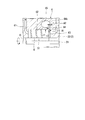
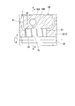
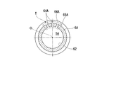
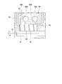
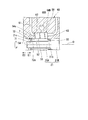
- FIG. 6 It is a mimetic diagram explaining a compressor system in an embodiment of the invention. It is a longitudinal cross-sectional view which shows the detail of the compressor and centrifuge shown in FIG. 1 in 1st embodiment of this invention, Comprising: It is the figure turned to right and left opposite with respect to FIG. It is a principal part enlarged view of the centrifuge shown in FIG. It is a longitudinal cross-sectional view which shows the detail of the compressor and centrifuge shown in FIG. 1 in 2nd embodiment of this invention, Comprising: It is the figure turned to right and left opposite with respect to FIG. It is a principal part enlarged view which shows the casing around the centrifuge of FIG. FIG. 6 is a cross-sectional view taken along line AA shown in FIG.
- FIG. 5 shows a first accommodation space. It is a figure which shows the 1st accommodation space by a 1st modification, Comprising: It is a figure corresponding to FIG. It is a longitudinal cross-sectional view which shows the casing around the centrifuge by a 2nd modification, Comprising: It is a figure corresponding to FIG. It is a longitudinal cross-sectional view which shows the detail of the compressor and centrifuge shown in FIG. 1 in 3rd embodiment of this invention, Comprising: It is the figure turned to right and left opposite with respect to FIG. It is a principal part enlarged view of the centrifuge shown in FIG.
- the compressor system 1 is used in a submarine production system (Subsea Production System), which is one of the offshore oil and gas field development methods, and is installed in the bottom of the ocean, or in a floating body oil storage facility (floating production storage and offloading, FPSO) It is used on the sea.
- the compressor system 1 pumps a production fluid such as oil and gas collected from a production well of an oil and gas field existing at several hundred to several thousand m in the seabed as a working fluid.
- the compressor system 1 includes a compressor 2, a motor 3 (drive unit), a bearing unit 4 (drive unit), a centrifugal separator 5, and a casing 6.
- the compressor 2 includes a shaft 21 that extends in the axis O direction (left and right direction in FIG. 1) as a rotation axis.
- the motor 3 has a rotor 31 that is directly connected to the shaft 21.
- the bearing portion 4 supports the shaft 21.
- the centrifuge 5 is provided on the upstream side of the first impeller 22 of the compressor 2.
- the casing 6 accommodates the motor 3, the compressor 2, and the centrifuge 5.
- the compressor 2 is accommodated in the casing 6.
- the compressor 2 compresses the working fluid by rotating the shaft 21 around the axis O together with the rotor 31.
- the compressor 2 of this embodiment includes a shaft 21, a first impeller 22, and a housing 23.
- the shaft 21 extends in the direction of the axis O.
- the first impeller 22 is fixed to the outer peripheral surface of the shaft 21.
- the housing 23 accommodates the first impeller 22.
- the shaft 21 is a rotating shaft extending in the direction of the axis O.
- the shaft 21 is supported by the casing 6 so as to be rotatable around the axis O.
- the shaft 21 passes through the housing 23.
- the shaft 21 extends from the housing 23 at both ends.
- the shaft 21 extends in the direction of the axis O in the casing 6 described later.
- the first impeller 22 rotates around the axis O together with the shaft 21 to compress the working fluid that passes through the first impeller 22 to generate a compressed fluid. That is, the first impeller 22 pumps the working fluid flowing in from the direction of the axis O outward in the radial direction.
- the housing 23 is an exterior of the compressor 2. The housing 23 accommodates the first impeller 22 therein. The housing 23 is accommodated in the casing 6.
- the motor 3 is accommodated in the casing 6 with an interval in the direction of the axis O with respect to the compressor 2.
- the motor 3 has a rotor 31 and a stator 32.
- the rotor 31 is fixed so as to be integrated with the shaft 21.
- the stator 32 is disposed on the outer peripheral side of the rotor 31.
- the rotor 31 is integrated with the shaft 21 so as to be rotatable around the axis O.
- the rotor 31 is directly connected to the outer peripheral side of the shaft 21, which is the outer side in the circumferential direction with respect to the axis O, so as to rotate integrally with the shaft 21 of the compressor 2 without using a gear or the like.
- the rotor 31 has, for example, a rotor core (not shown) through which an induced current flows when the stator 32 generates a rotating magnetic field.
- the stator 32 is provided with a gap 33 in the circumferential direction so as to cover the rotor 31 from the outer peripheral side.
- the stator 32 has, for example, a plurality of stator cores (not shown) arranged along the circumferential direction of the rotor 31, and a stator winding (not shown) wound around the stator core.
- the stator 32 rotates the rotor 31 by generating a rotating magnetic field when an electric current flows from the outside.
- the stator 32 is fixed in the casing 6.
- the bearing portion 4 is accommodated in the casing 6.
- the bearing part 4 supports the shaft 21 rotatably.
- the bearing portion 4 of this embodiment includes a plurality of journal bearings 41 and thrust bearings 42.
- the journal bearing 41 supports a load acting on the shaft 21 in the radial direction with respect to the axis O.
- the journal bearings 41 are disposed at both ends of the shaft 21 in the axis O direction so as to sandwich the motor 3 and the compressor 2 from the axis O direction.
- the journal bearing 41 is disposed between the area where the compressor 2 is provided and the area where the motor 3 is provided, and is also arranged closer to the motor 3 than the seal member 60 described later.
- the thrust bearing 42 supports a load that acts on the shaft 21 in the direction of the axis O via a thrust collar 21 a formed on the shaft 21.
- the thrust bearing 42 is disposed between the area where the compressor 2 is provided and the area where the motor 3 is provided, and is disposed closer to the compressor 2 than the seal member 60 described later.
- the centrifuge 5 is provided on the upstream side of the compressor 2 as shown in FIG.
- the centrifuge 5 is formed larger than the outer diameter of the inlet of the first impeller 22 of the compressor 2.
- the centrifuge 5 is rotated around the axis O by the shaft 21 together with the motor 3. Thereby, the centrifugal separator 5 is configured to send the working fluid supplied from the outside toward the first impeller 22 while swirling.
- the centrifuge 5 is provided separately from the first impeller 22 of the compressor 2.
- the centrifuge 5 is accommodated in the casing 6.
- the centrifugal separator 5 is a separator including a second impeller 51 fixed to the outer peripheral surface of the shaft 21 of the compressor 2 extending in the direction of the axis O.
- the radius r1 of the second impeller 51 of the centrifuge 5 is set to be larger than the radius r2 of the inlet of the first impeller 22 of the compressor 2 (r1> r2).
- the rotating shaft of the centrifuge 5 is common with the shaft 21 of the compressor 2, it may be provided separately.
- the second impeller 51 rotates around the axis O together with the shaft 21.
- the second impeller 51 pumps the working fluid flowing in from the direction of the axis O and passing through the inside of the second impeller 51 toward the outside of the axis O and the radial direction by centrifugal force.
- the casing 6 has a cylindrical shape along the axis O as shown in FIG.
- the casing 6 accommodates the compressor 2, the motor 3, and the centrifuge 5 therein.
- the inner surface of the casing 6 protrudes toward the shaft 21 between the compressor 2 and the motor 3 in the direction of the axis O.
- a protruding member of the casing 6 is provided with a seal member 60 that seals between a region where the compressor 2 is provided, a region where the centrifugal separator 5 is provided, and a region where the motor 3 is provided.
- the casing 6 defines an inflow passage 61, a first accommodation space 62, a second accommodation space 63, a foreign matter discharge passage 64, and a foreign matter collection chamber 65.
- the inflow channel 61 guides the working fluid from the outside to the centrifuge 5.
- the first accommodation space 62 is disposed on the downstream side of the inflow channel 61 and accommodates the centrifuge 5.
- the second housing space 63 is connected to the downstream side of the first housing space 62 and houses the first impeller 22 of the compressor 2.
- the foreign matter discharge channel 64 is connected to the downstream side of the first accommodation space 62 in the direction of the axis O, and discharges foreign matter in the working fluid guided to the outer peripheral side by the centrifuge 5.
- the foreign matter collection chamber 65 communicates with the foreign matter discharge channel 64.
- the first accommodation space 62 has an inflow channel 61 communicating with one end side.
- the first accommodation space 62 communicates with the second accommodation space 63 and the foreign matter discharge channel 64 on the other end side.
- the first accommodation space 62 takes in external working fluid from the inflow channel 61.
- the first storage space 62 is an internal space formed in the casing 6 so as to rotatably store the second impeller 51 of the centrifuge 5.
- the foreign matter discharge channel 64 extends from the first accommodation space 62 in the axial direction toward the compressor 2 side and radially outward.
- the foreign substance discharge flow path 64 is gradually reduced in diameter as the flow path cross section of the foreign substance discharge flow path 64 moves from the upstream side to the downstream side. That is, the upstream cross section A1 on the first storage space 62 side of the foreign matter discharge channel 64 shown in FIG. 3 is larger than the downstream cross section A2 located on the foreign matter collection chamber 65 side.
- the foreign matter discharge passages 64 are arranged in a plurality (two places at the top and bottom in the drawing) in the circumferential direction around the axis O.
- the foreign substance collection chamber 65 is formed in the casing 6.
- the foreign substance collection chamber 65 extends over the entire circumference along a circumferential direction that circulates around the axis O.
- the foreign substance collection chamber 65 is connected to the downstream end (exit part 64 b) of the foreign substance discharge flow path 64.
- the swirled working fluid is sent out toward the first impeller 22 of the compressor 2 disposed on the downstream side of the centrifugal separator 5. At this time, in the first accommodating space 62, a foreign substance having a large mass in the working fluid is guided radially outward by the centrifugal force generated by the centrifugal separator 5.
- the centrifuge 5 has a larger diameter than the inlet of the first impeller 22, and a foreign matter discharge flow path 64 is connected to the stepped portion between the outlet outer diameter portion of the centrifuge 5 and the impeller inlet outer diameter portion of the compressor 2. Has been. As a result, the foreign matter sent out along the radially outer side flows into the foreign matter discharge channel 64 and is collected in the foreign matter collection chamber 65.
- Another working fluid having a mass smaller than that of the foreign matter flowing into the foreign matter discharge flow path 64 is sent out in the axial direction, and flows into the first impeller 22 of the compressor 2 on the downstream side of the first accommodation space 62, and the first impeller 22. Is pumped radially outward by the rotation of. Therefore, the foreign matter contained in the working fluid is separated on the upstream side of the first impeller 22. Thereby, the mixing of foreign matter into the first impeller 22 can be suppressed, and damage to the first impeller 22 can be prevented.
- the foreign matter discharge channel 64 is connected to the radially outer side on the downstream side of the centrifuge 5.
- the liquid can be guided radially outward by the centrifugal force of the centrifugal separator 5 and collected by the foreign matter discharge flow path 64.
- the function of gas-liquid separation can be provided. Therefore, when the production fluid mixed with crude oil or natural gas collected by the seabed production system as in the first embodiment is used as the working fluid, gas-liquid separation can be performed efficiently, and an excellent effect is exhibited. be able to.
- the foreign matter discharge flow path 64 extends from the first accommodation space 62 toward the first impeller 22 in the axial direction and radially outward. Therefore, the direction of the flow path of the inflow portion of the foreign matter discharge flow path 64 is a shape that matches the flow direction of the foreign matter guided by the centrifugal force of the centrifuge 5. Thereby, a foreign material can be efficiently flowed into the foreign material discharge channel 64.
- a foreign matter collecting chamber 65 communicating with the foreign matter discharge channel 64 is defined in the casing 6. Therefore, the foreign matter that has flowed into the foreign matter discharge channel 64 can be collected and collected in the foreign matter collection chamber defined in the casing 6.
- the diameter of the foreign substance discharge flow path 64 is gradually reduced from the upstream side toward the downstream side. Therefore, the pressure can be reduced by increasing the flow rate of the working fluid (foreign matter) passing through the foreign matter discharge channel 64. Thereby, it can suppress that the casing 6 is damaged by the pressure of the foreign material which passed the foreign material discharge flow path 64.
- the foreign matter in the working fluid is efficiently separated, so that the foreign matter can be prevented from entering the first impeller 22 of the compressor 2 and the first impeller 22 is damaged. Can be prevented.
- a plurality of foreign matter discharge passages 64 are arranged in the circumferential direction (for example, two locations in the upper and lower directions in FIG. 2), but the number of installation locations can be set as appropriate, and only one location is provided. May be.
- Second Embodiment a compressor system according to a second embodiment will be described with reference to FIGS.
- the same components as those in the first embodiment are denoted by the same reference numerals, and detailed description thereof is omitted.
- the compressor system of the second embodiment is partially different from the first embodiment with respect to the centrifuge.
- the centrifuge 5A of the second embodiment is provided on the upstream side of the compressor 2 as shown in FIG.
- the centrifugal separator 5 ⁇ / b> A is formed larger than the outer diameter of the inlet of the first impeller 22 of the compressor 2.
- the centrifugal separator 5 ⁇ / b> A is rotated around the axis O by the shaft 21 together with the motor 3. Accordingly, the centrifugal separator 5A is configured to send out the working fluid supplied from the outside toward the first impeller 22 while swirling.
- the centrifugal separator 5 ⁇ / b> A is provided separately from the first impeller 22 of the compressor 2.
- the centrifuge 5A is accommodated in the casing 6A.
- the centrifugal separator 5A is a separator including a second impeller 51 fixed to the outer peripheral surface of the shaft 21 of the compressor 2 extending in the axis O direction.
- the rotating shaft of the centrifugal separator 5A is common with the shaft 21 of the compressor 2, it may be provided separately.
- the second impeller 51 rotates around the axis O together with the shaft 21, and pumps the working fluid that flows in from the direction of the axis O and passes through the second impeller 51 toward the outside of the axis O and the radial direction by centrifugal force.
- the casing 6A has a cylindrical shape along the axis O as shown in FIG.
- the casing 6A accommodates the compressor 2, the motor 3, and the centrifuge 5A inside.
- the inner surface of the casing 6A protrudes toward the shaft 21 between the compressor 2 and the motor 3 in the axis O direction.
- a protruding member of the casing 6A is provided with a seal member 60 that seals between a region where the compressor 2 is provided, a region where the centrifugal separator 5A is provided, and a region where the motor 3 is provided.
- the casing 6A defines an inflow passage 61, a first accommodation space 62, a second accommodation space 63, a foreign matter discharge passage 64A, and a foreign matter collection chamber 65A.
- the inflow channel 61 guides the working fluid from the outside to the centrifuge 5A.
- the first storage space 62 is disposed on the downstream side of the inflow channel 61 and stores the centrifuge 5A.
- the second housing space 63 is connected to the downstream side of the first housing space 62 and houses the first impeller 22 of the compressor 2.
- the foreign matter discharge channel 64A extends radially outward from the first accommodation space 62 and discharges foreign matter in the working fluid guided to the outer peripheral side by the centrifuge 5A.
- the foreign matter collection chamber 65A communicates with the foreign matter discharge channel 64A.
- the first accommodation space 62 has an inflow channel 61 communicating with one end side.
- the first accommodation space 62 communicates with the second accommodation space 63 on the other end side.
- the first accommodation space 62 takes in external working fluid from the inflow channel 61.
- the first accommodation space 62 is an internal space formed in the casing 6A so as to rotatably accommodate the second impeller 51 of the centrifuge 5A.
- the foreign matter discharge channel 64 ⁇ / b> A is attached to an intermediate portion in the axial direction of the first accommodation space 62. As shown in FIG. 6, the foreign matter discharge flow path 64 ⁇ / b> A is arranged at one place (upper side in the drawing) in the circumferential direction around the axis O.
- the foreign matter discharge channel 64A has a hole shape, and the channel cross section has the same cross section from the inlet to the outlet.
- the foreign matter collecting chamber 65A is formed in the casing 6A.
- the foreign matter collecting chamber 65A extends over the entire circumference along the circumferential direction around the axis O.
- the foreign substance collection chamber 65A is connected to the downstream end (exit part 64b) of the foreign substance discharge flow path 64A.
- the foreign matter discharge flow path 64 ⁇ / b> A has a configuration in which the entire circumferential direction is not connected to the first accommodation space 62. Therefore, in the foreign matter discharge channel 64A, working fluids having different pressures in the circumferential direction flow into the same foreign matter collecting chamber 65A, and the working fluid in the foreign matter collecting chamber 65A collected by the different pressures is the first. It is the structure which can suppress returning in the accommodation space 62.
- the swiveled working fluid is sent out toward the first impeller 22 of the compressor 2 disposed on the downstream side of the centrifugal separator 5A. At this time, in the first accommodating space 62, a foreign substance having a large mass in the working fluid is guided radially outward by the centrifugal force generated by the centrifugal separator 5A.
- the foreign matter guided radially outward by the centrifuge 5A flows into the foreign matter discharge channel 64A extending radially outward from the first storage space 62, and is discharged and collected. .
- Another working fluid having a mass smaller than that of the foreign matter flowing into the foreign matter discharge channel 64A is sent out in the direction of the axis O, and flows into the first impeller 22 of the compressor 2 on the downstream side of the centrifugal separator 5A. Is pumped radially outward by the rotation of. Therefore, the foreign matter contained in the working fluid is separated on the upstream side of the first impeller 22. Thereby, the mixing of foreign matter into the first impeller 22 can be suppressed, and damage to the first impeller 22 can be prevented.
- the foreign matter discharge flow path 64 ⁇ / b> A is connected so as to extend outward in the radial direction of the first accommodation space 62.
- the foreign matter discharge flow path 64 ⁇ / b> A is a smooth flow path along the direction of the axis O without forming a step or the like in the first storage space 62 and in a connection portion between the first storage space 62 and the second storage space 63. Yes. Thereby, generation
- the liquid when liquid is mixed in a fluid mainly composed of gas, the liquid can be guided radially outward by the centrifugal force of the centrifugal separator 5A and collected by the foreign matter discharge flow path 64A. Therefore, the function of gas-liquid separation can be provided. Therefore, when the production fluid mixed with crude oil or natural gas collected by the submarine production system as in the present embodiment is used as the working fluid, gas-liquid separation can be performed efficiently, and an excellent effect is exhibited. be able to.
- the foreign matter collection chamber 65A extends over the entire circumference in the circumferential direction. Therefore, if a plurality of foreign matter discharge channels 64A are arranged for one foreign matter collection chamber 65A, foreign matters discharged from a plurality of locations can be efficiently collected and collected in one foreign matter collection chamber 65A. it can.
- the foreign matter discharge flow path 64A is configured to be connected to an intermediate portion in the direction of the axis O of the first accommodation space 62, but the connection position in the direction of the axis O is limited to this. Absent. For example, a position near the upstream inflow channel 61 in the direction of the axis O of the first housing space 62 may be used, or a position near the second housing space 63 on the downstream side may be used.
- a plurality of foreign matter discharge channels 64 ⁇ / b> A are provided in the circumferential direction (three locations in the upper region in FIG. 7). It is good also as a structure arrange
- a fluid (foreign matter) having the same pressure can be caused to flow into the plurality of foreign matter discharge channels 64A arranged along the circumferential direction. Therefore, the pressure balance of the working fluid in the first accommodation space 62 can be stabilized, and foreign matters that have flowed into the foreign matter discharge flow path 64A can be prevented from returning into the first accommodation space 62.
- the second modification shown in FIG. 8 has a configuration in which a plurality (two in this case) of foreign matter discharge passages 64A are provided along the axis O direction of the first accommodation space 62 in the casing 6A.
- a foreign matter collection chamber 65A extending along the circumferential direction is provided for each foreign matter discharge channel 64A.
- the working fluid (foreign matter) guided radially outward by the centrifugal force of the centrifugal separator 5A is stepped by the two foreign matter discharge channels 64A and 64A along the axis O direction of the first accommodation space 62. Therefore, the function of gas-liquid separation can be improved.
- the pitch of the foreign matter discharge channels 64 in the direction of the axis O is centrifuged. It is preferable to match the pitch of the second impeller 51 of the machine 5A.
- the shape of the second impeller 51 of the centrifuge 5, 5A, the cross-sectional area of the foreign matter discharge passages 64, 64A, the extension length, and the cross section of the foreign matter collection chambers 65, 65A The configuration such as the shape can be set as appropriate.
- the foreign substance collection chambers 65, 65A are configured to extend over the entire circumference in the circumferential direction, but may be provided in a part in the circumferential direction.
- the centrifuge 5B of the third embodiment is provided on the upstream side of the compressor 2 as shown in FIG.
- the centrifugal separator 5 ⁇ / b> B is formed larger than the outer diameter of the inlet of the first impeller 22 of the compressor 2.
- the centrifugal separator 5 ⁇ / b> B is rotated around the axis O by the shaft 21 together with the motor 3. Accordingly, the centrifugal separator 5B is configured to send out the working fluid supplied from the outside toward the first impeller 22 while swirling.
- the centrifugal separator 5 ⁇ / b> B is provided separately from the first impeller 22 of the compressor 2.
- the centrifuge 5B is accommodated in the casing 6B.
- the centrifugal separator 5B is a separator including a second impeller 51 fixed to the outer peripheral surface of the shaft 21 of the compressor 2 extending in the axis O direction.
- the rotating shaft of the centrifuge 5B is common with the shaft 21 of the compressor 2, it may be provided separately.
- a portion of the shaft 21 to which the centrifugal separator 5B is attached will be described as a rotating shaft 21A.
- the second impeller 51 rotates around the axis O together with the shaft 21 (rotating shaft 21A), and the working fluid that flows in from the direction of the axis O and passes through the second impeller 51 is directed outward in the axis O direction and in the radial direction by centrifugal force. To pump.
- the casing 6B has a cylindrical shape along the axis O as shown in FIG.
- the casing 6B accommodates the compressor 2, the motor 3, and the centrifuge 5B inside.
- the inner surface of the casing 6B protrudes toward the shaft 21 between the compressor 2 and the motor 3 in the direction of the axis O.
- a protruding member of the casing 6B is provided with a seal member 60 that seals between a region where the compressor 2 is provided, a region where the centrifugal separator 5B is provided, and a region where the motor 3 is provided.
- the casing 6B defines an inflow passage 61, a first accommodation space 62, a second accommodation space 63, a foreign matter discharge passage 64B, and a foreign matter collection chamber 65B.
- the inflow channel 61 guides the working fluid from the outside to the centrifuge 5B.
- the first storage space 62 is disposed on the downstream side of the inflow channel 61 and stores the centrifuge 5B.
- the second housing space 63 is connected to the downstream side of the first housing space 62 and houses the first impeller 22 of the compressor 2.
- the foreign matter discharge channel 64B extends radially outward from the first accommodation space 62 and discharges foreign matter in the working fluid guided to the outer peripheral side by the centrifuge 5B.
- the foreign matter collection chamber 65B communicates with the foreign matter discharge channel 64B.
- the first accommodation space 62 has an inflow channel 61 communicating with one end side.
- the first accommodation space 62 communicates with the second accommodation space 63 on the other end side.
- the first accommodation space 62 takes in external working fluid from the inflow channel 61.
- the first accommodation space 62 is an internal space formed in the casing 6B so as to rotatably accommodate the second impeller 51 of the centrifuge 5B.
- the foreign matter discharge channel 64 ⁇ / b> B is attached to an intermediate portion in the axial direction of the first accommodation space 62.
- the foreign matter discharge channel 64B is arranged at one place (upper side in the drawing) in the circumferential direction around the axis O.
- the foreign matter discharge channel 64B has a hole shape, and the channel cross section is the same from the inlet to the outlet.
- the foreign matter collection chamber 65B is formed in the casing 6B.
- the foreign matter collecting chamber 65B extends over the entire circumference along the circumferential direction around the axis O.
- the foreign substance collection chamber 65B is connected to the downstream end of the foreign substance discharge flow path 64B.
- the centrifuge 5B is provided with a convex portion 53 and a convex portion 54 that protrude from the base portion 52 on the rotating shaft 21A side toward both sides in the direction of the axis O.
- the convex portion 53 and the convex portion 54 are provided in a flange shape over the entire circumference in the circumferential direction.
- one first convex portion 53 is pressed from the outer peripheral side by a pressing concave portion 21b provided on the rotating shaft 21A.
- the other second convex portion 54 is pressed from the outer peripheral side by a fitting nut 7 (fitting member) that is detachable from the rotating shaft 21A.
- the rotating shaft 21A of the shaft 21 is formed to have a smaller diameter than the portion of the other shaft 21 (the pressing portion 21B shown in FIG. 10).
- a step portion is formed at a connection portion between the rotating shaft 21A and the pressing portion 21B.
- the holding recess 21b is open at this step so as to face the upstream side in the axis O direction (centrifuge 5B side).
- the holding recess 21b is formed over the entire circumference in the circumferential direction.
- the fitting nut 7 includes a female screw portion 71 and a fitting recess 72.
- the female thread portion 71 is provided coaxially with the rotation shaft 21A.
- the female thread portion 71 is formed on the outer peripheral surface of the rotating shaft 21A.
- the fitting recess 72 is fitted to the second protrusion 54 from the outer peripheral side.
- a taper surface is formed on the inner peripheral surface 72 a of the fitting recess 72.
- the tapered surface gradually expands outward in the radial direction from the upstream side toward the downstream side.
- the centrifuge 5B is attached to the rotating shaft 21A.
- the first convex portion 53 and the second convex portion 54 that protrude from the base portion 52 of the centrifuge 5B to both sides in the axis O direction are pressed from the outer peripheral side by the pressing portion 21B of the shaft 21 and the fitting nut 7, respectively. It is in the state. That is, the base 52 of the centrifuge 5B is pressed in the direction opposite to the centrifugal force acting on the radially outer side. Therefore, the proof strength against centrifugal force can be increased.
- the fitting nut 7 that presses the other second convex portion 54 from the outer peripheral side is detachable from the rotating shaft 21A. Therefore, the fitting nut 7 with respect to the rotating shaft 21A is released by moving the fitting nut 7 to the upstream side (arrow E2 direction) by rotating the screw in the loosening direction (arrow E2 direction). Thereby, pressing of the second convex portion 54 can be released, and the centrifuge 5B can be easily detached from the rotating shaft 21A. Thus, it becomes possible to improve the work efficiency concerning attachment / detachment of the centrifuge 5B. Therefore, maintenance such as replacement or cleaning of the centrifuge 5B can be performed efficiently.
- the work efficiency can be improved by simply performing the detachment work, and the resistance to centrifugal force can be improved.
- the present invention is not limited to the above-described third embodiment, and can be appropriately changed without departing from the gist thereof.
- the pressing portion provided integrally with the rotating shaft 21A is targeted to the pressing portion 21B that is a part of the shaft 21.
- the pressing portion is not limited to this portion.
- the pressing portion may be the rotor 31 as a pressing portion provided integrally with the rotating shaft 21A. In this case, the rotor 31 can be pressed against the first convex portion 53 on the entire circumference, so that stable and high strength can be ensured.
- the position to be fitted by the fitting member is the upstream side of the centrifuge 5B in the axis O direction.
- the centrifuge 5B may be divided in the circumferential direction.
- segmented into the circumferential direction can be removed from the rotating shaft 21A only by canceling
- the fitting member is the nut-type fitting nut 7 as described above, it is not necessary to completely remove the fitting member from the rotating shaft.
- the fitting member is not limited to the shape and size of the fitting nut 7 as in the present embodiment, and other shapes and forms may be employed. Configurations such as the shape, size, position, quantity, and the like of the centrifuge 5B, the foreign matter discharge channel 64B, and the foreign matter collection chamber 65B can be appropriately set.
- the foreign matter in the fluid is efficiently separated, so that the foreign matter can be prevented from being mixed into the impeller and the impeller can be prevented from being damaged.
- centrifugal separator mounting structure it is possible to improve the working efficiency and to improve the resistance to centrifugal force by simply performing the attaching / detaching work.
Landscapes
- Engineering & Computer Science (AREA)
- Mechanical Engineering (AREA)
- General Engineering & Computer Science (AREA)
- Chemical & Material Sciences (AREA)
- Chemical Kinetics & Catalysis (AREA)
- Structures Of Non-Positive Displacement Pumps (AREA)
- Centrifugal Separators (AREA)
Abstract
軸線方向から流入する流体を径方向外側に圧送する圧縮機(2)の第一インペラ(22)と、外部から供給される流体を旋回させながら第一インペラ(22)に向かって送り出す遠心分離機(5)と、流体を外部から遠心分離機(5)に導く流入流路(61)、流入流路(61)の下流側に配置されて遠心分離機(5)を収容する第一収容空間(62)、第一収容空間(62)の下流側に接続されて第一インペラ(22)を収容する第二収容空間(63)、及び、遠心分離機(5)により外周側に導かれた異物を排出する異物排出流路(64)を画成するケーシング(6)と、を備える。
Description
本発明は、コンプレッサシステム、及び遠心分離機の取付け構造に関する。
本願は、2015年3月20日に出願された特願2015-058367号、2015年3月20日に出願された特願2015-058368号、及び2015年3月20日に出願された特願2015-058681号について優先権を主張し、その内容をここに援用する。
本願は、2015年3月20日に出願された特願2015-058367号、2015年3月20日に出願された特願2015-058368号、及び2015年3月20日に出願された特願2015-058681号について優先権を主張し、その内容をここに援用する。
モータと圧縮機とが一体となっているコンプレッサシステム(モータ圧縮機)は、空気やガス等の気体を圧縮する圧縮機と、圧縮機を駆動させるモータとを有している。コンプレッサシステム(モータ圧縮機)では、圧縮機のケーシングから延在する回転軸と、モータのケーシングから同様に延在するモータの回転軸とが接続されている。モータの回転が圧縮機に伝達される。このモータ及び圧縮機の回転軸は、複数の軸受により支持されることで安定して回転する。
このようなコンプレッサシステム(モータ圧縮機)は、例えば、非特許文献1のような海底生産システム(Subsea Production System)や、非特許文献2のような浮体式海洋石油貯蔵設備(Floating Production Storage and Offloading、FPSO)に使用される。海底生産システムに使用される際には、コンプレッサシステム(モータ圧縮機)は、海底に設置され、海底から数千mの深さまで掘削した生産井から原油や天然ガス等が混在した生産流体を海上に送り出している。浮体式海洋石油貯蔵設備に使用される際には、コンプレッサシステム(モータ圧縮機)は、船舶等の海上設備に設置されている。
三菱重工技報 Vol.34 No.5
Turbomachinery International September/October 2014
しかしながら、従来のコンプレッサシステムでは、原油や天然ガス等が混在した生産流体が気液分離してから圧縮機に供給される。そのため、圧縮機の上流側に気液分離用の遠心ポンプが設けてられている。ところが、遠心ポンプを使用する場合には、キャップビテーションが発生すると水頭が低下しポンプの機能が低下する可能性がある。その点で改善の余地があった。
ポンプ機能が低下し気液分離が不十分になると、流体中に液体(異物)が混入したまま圧縮機に導入される。そのため、圧縮機のインペラが損傷するという問題があった。
ポンプ機能が低下し気液分離が不十分になると、流体中に液体(異物)が混入したまま圧縮機に導入される。そのため、圧縮機のインペラが損傷するという問題があった。
このような遠心ポンプは、圧縮機の上流側に設けられている。遠心ポンプでは、導入される流体中に異物が多く含まれる。そのため、遠心ポンプでは、摩耗の進行が早く、交換頻度が多くなっている。従来の遠心ポンプはボルト締結により固定されているのが一般的である。ところが、制限されたスペース内でのボルトによる着脱作業となることから、作業効率を向上させることが求められている。その点で改善の余地があった。
大きな遠心力を発生させる遠心ポンプに対してボルトの耐力が不足した場合に、遠心ポンプが安定した状態を維持することができないおそれがあった。
本発明は、上述する問題点に鑑みてなされたもので、流体内の異物を効率よく分離することで、インペラへの異物の混入を抑制することができ、インペラの損傷を防止することが可能となるコンプレッサシステムを提供することを第一の目的とする。
本発明は、上述する問題点に鑑みてなされたもので、着脱作業を簡単に行うことで、作業効率を向上させることができ、しかも遠心力に対する耐力を向上させることができる遠心分離機の取付け構造を提供することを第二の目的とする。
上記第一の目的を達成するため、本発明の第一の態様におけるコンプレッサシステムは、駆動部と、該駆動部によって軸線回りに回転されることで軸方向から流入する流体を径方向外側に圧送するインペラと、前記インペラの上流側に設けられて、前記インペラの入口の外径よりも大きく形成されるとともに前記駆動部によって前記軸線回りに回転されることで、外部から供給される流体を旋回させながら前記インペラに向かって送り出す遠心分離機と、流体を外部から前記遠心分離機に導く流入流路、該流入流路の下流側に配置されて前記遠心分離機を収容する第一収容空間、前記第一収容空間の下流側に接続されて前記インペラを収容する第二収容空間、及び、前記第一収容空間の下流側に軸方向に接続されて前記遠心分離機により外周側に導かれた異物を排出する異物排出流路を画成するケーシングと、を備える。
このような構成によれば、流入流路より外部から第一収容空間に供給された流体は、第一収容空間内に収容され駆動部によって軸線回りに回転する遠心分離機によって旋回させられる。旋回させられた流体は、遠心分離機の下流側に配置されるインペラに向けて送り出される。このとき、第一収容空間において、流体中の質量の大きな異物は遠心分離機によって生じる遠心力で径方向外側に導かれることになる。流体のうち遠心分離機で軸方向かつ径方向外側に向けて導かれた異物は、第一収容空間の下流側に接続されている異物排出流路に流入して排出される。つまり、遠心分離機がインペラの入口よりも大径となっており、遠心分離機の出口外径部とインペラ入口外径部の段差部分に異物排出流路が接続されている。そのため、径方向外側に沿って送り出された異物が異物排出流路に流入されて回収されることになる。
異物排出流路に流入した異物よりも質量の小さな他の流体は軸方向に送り出されるとともに遠心分離機の下流側のインペラに流入され、インペラの回転によって径方向外側に圧送される。そのため、流体内に含まれる異物がインペラの上流側で分離される。これにより、インペラへの異物の混入を抑制することができ、インペラの損傷を防止することが可能となる。
異物排出流路に流入した異物よりも質量の小さな他の流体は軸方向に送り出されるとともに遠心分離機の下流側のインペラに流入され、インペラの回転によって径方向外側に圧送される。そのため、流体内に含まれる異物がインペラの上流側で分離される。これにより、インペラへの異物の混入を抑制することができ、インペラの損傷を防止することが可能となる。
このように本発明では、異物排出流路が遠心分離機の下流側で径方向外側に接続されている。これにより、遠心力によって径方向外側に導かれる異物を効率よく回収することができる。そのため、例えば気体を主とする流体に液体が混在している場合には、液体を遠心分離機の遠心力で径方向外側に導いて異物排出流路で回収することが可能となる。これにより、気液分離の機能をもたせることができる。
本発明の第二の態様におけるコンプレッサシステムでは、第一の態様において、前記異物排出流路は、前記第一収容空間から軸方向で前記インペラ側、かつ前記径方向外側に向けて延在していることが好ましい。
このような構成によれば、異物排出流路の流入部分の流路の向きが遠心分離機の遠心力によって導かれる異物の流れの向きに合せた形状となる。そのため、効率よく異物を異物排出流路内に流入させることができる。
本発明の第三の態様におけるコンプレッサシステムは、第一又は第二の態様において、前記ケーシングには、前記異物排出流路に連通する異物回収用チャンバーが画成されていることが好ましい。
このような構成によれば、異物排出流路に流入した異物をケーシングに画成された異物回収用チャンバー内に集めて回収することができる。
本発明の第四の態様におけるコンプレッサシステムは、第一から第三のいずれか一つの態様において、前記異物排出流路の流路断面は、上流側から下流側に向かうに従い漸次、縮径されていることが好ましい。
このような構成によれば、異物排出流路内を通過する流体(異物)の流速を大きくして圧力を低下させることができ、これにより異物排出流路を通過した異物の圧力よってケーシングが損傷することを抑制することができる。
上記第一の目的を達成するため、本発明の第五の態様におけるコンプレッサシステムは、駆動部と、該駆動部によって軸線回りに回転されることで軸方向から流入する流体を径方向外側に圧送するインペラと、前記インペラの上流側に設けられて、前記駆動部によって前記軸線回りに回転されることで、外部から供給される流体を旋回させながら前記インペラに向かって送り出す遠心分離機と、流体を外部から前記遠心分離機に導く流入流路、該流入流路の下流側に配置されて前記遠心分離機を収容する第一収容空間、前記第一収容空間の下流側に接続されて前記インペラを収容する第二収容空間、及び、前記第一収容空間から径方向外側に延びて前記遠心分離機により外周側に導かれた異物を排出する異物排出流路を画成するケーシングと、を備える。
このような構成によれば、流入流路より外部から第一収容空間に供給された流体は、第一収容空間内に収容され駆動部によって軸線回りに回転する遠心分離機によって旋回させられる。旋回させられた流体は、遠心分離機の下流側に配置されるインペラに向けて送り出される。このとき、第一収容空間において、流体中の質量の大きな異物は遠心分離機によって生じる遠心力で径方向外側に導かれることになる。流体のうち遠心分離機で径方向外側に向けて導かれた異物は、第一収容空間から径方向外側に延びる異物排出流路に流入して排出されて回収されることになる。
異物排出流路に流入した異物よりも質量の小さな他の流体は軸方向に送り出されるとともに遠心分離機の下流側のインペラに流入され、インペラの回転によって径方向外側に圧送される。そのため、流体内に含まれる異物がインペラの上流側で分離される。これにより、インペラへの異物の混入を抑制することができ、インペラの損傷を防止することが可能となる。
異物排出流路に流入した異物よりも質量の小さな他の流体は軸方向に送り出されるとともに遠心分離機の下流側のインペラに流入され、インペラの回転によって径方向外側に圧送される。そのため、流体内に含まれる異物がインペラの上流側で分離される。これにより、インペラへの異物の混入を抑制することができ、インペラの損傷を防止することが可能となる。
このように本発明では、異物排出流路が第一収容空間の径方向外側に向けて延在するように接続される構成となっている。異物排出流路が、第一収容空間内、および第一収容空間と第二収容空間との接続部分に段差などが形成されず軸方向に沿って滑らかな流路となっている。これにより、乱流の発生が抑えられ、遠心力によって径方向外側に導かれる異物を効率よく回収することができる。そのため、例えば気体を主とする流体に液体が混在している場合には、液体を遠心分離機の遠心力で径方向外側に導いて異物排出流路で回収することが可能となる。そのため、気液分離の機能をもたせることができる。
本発明の第六の態様におけるコンプレッサシステムは、第五の態様において、前記ケーシングには、前記異物排出流路に連通するとともに、前記軸線回りに周回する周方向に沿って全周にわたって延在する異物回収用チャンバーが画成されていることが好ましい。
このような構成によれば、複数の異物排出流路に流入した異物をケーシングに画成された周方向の全周にわたって延在する1つの異物回収用チャンバー内に集めて回収することができる。
本発明の第七の態様におけるコンプレッサシステムは、第五又は第六の態様において、前記異物排出流路は、前記軸線回りに周回する周方向に複数設けられている。これら異物排出流路は、前記第一収容空間の周方向で前記流体の圧力が同等になる圧力領域内に配置されていることが好ましい。
このような構成によれば、周方向に沿って配置される複数の異物排出流路に同等の圧力の流体(異物)を流入させることができるので、第一収容空間内の流体の圧力バランスを安定させることができ、異物排出流路内に流入した異物が第一収容空間内に戻ることを防止することができる。
本発明の第八の態様におけるコンプレッサシステムは、第五から第七のいずれか一つの態様において、前記異物排出流路は、前記第一収容空間の軸方向に沿って複数設けられていることが好ましい。
この場合には、遠心分離機の遠心力によって径方向外側に導かれた流体(異物)を、第一収容空間の軸方向に沿う複数箇所の異物排出流路によって段階的に回収することが可能となる。そのため、気液分離の機能を向上させることができる。
上記第二の目的を達成するため、本発明の第九の態様における遠心分離機の取付け構造は、駆動部によって軸線回りに回転されることで軸方向から流入する流体を径方向外側に圧送するインペラの上流側に設けられて、前記駆動部によって前記軸線と同軸の回転軸回りに回転されることで、外部から供給される流体を旋回させながら前記インペラに向かって送り出す遠心分離機の取付け構造であって、前記遠心分離機には、前記回転軸側の基部から前記軸方向の両側に向けて突出する凸部が設けられ、該凸部のうち一方の第一凸部は、前記回転軸に一体的に設けられた押さえ部に設けられた押さえ凹部によって外周側から押さえ付けられ、他方の第二凸部は、前記回転軸に対して着脱自在な嵌合部材によって外周側から押さえ付けられている。
このような構成によれば、遠心分離機は、その基部から軸方向の両側に突出する凸部がそれぞれ押さえ部、嵌合部材によって外周側から押さえ付けられた状態で回転軸に取り付けられる。つまり、遠心分離機の基部が径方向外側に作用する遠心力とは反対の方向に押え付けられる。そのため、遠心力に対する耐力を高めることができる。しかも、一方の第一凸部は、例えば回転軸に一体的に設けられた押さえ部が駆動部のロータである場合には、ロータによって全周で押さえ付けられるので安定、かつ高い強度を確保することができる。
他方の第二凸部を外周側から押さえ付ける嵌合部材は、回転軸に対して着脱自在であるので、回転軸に対する嵌合部材の嵌合を解除することで、第二凸部の押さえ付けを解放することができ、容易に遠心分離機を回転軸から離脱させることができる。
このように遠心分離機の着脱にかかる作業効率を向上させることが可能となる。そのため、遠心分離機の交換、あるいは清掃などのメンテナンスを効率よく行うことができる利点がある。
このように遠心分離機の着脱にかかる作業効率を向上させることが可能となる。そのため、遠心分離機の交換、あるいは清掃などのメンテナンスを効率よく行うことができる利点がある。
本発明の第十の態様における遠心分離機の取付け構造は、前記嵌合部材は、前記回転軸に同軸に設けられ、かつ前記回転軸の外周面に螺着される雌ねじ部と、前記第二凸部に対して外周側から嵌合する嵌合凹部と、を備えていることが好ましい。
この場合には、遠心分離機を回転軸から取り外す際に、ナット形式の嵌合部材をねじが緩む方向に回転させて回転軸に対する螺着を解除する。これにより、第二凸部に対する嵌合凹部による押さえ付けを開放することができる。
本発明の第十一の態様における遠心分離機の取付け構造は、第九又は十の態様において、前記遠心分離機は、周方向に分割されていてもよい。
この場合には、嵌合部材の第二凸部に対する嵌合を解除することだけで、周方向に分割された遠心分離機を回転軸から取り外すことができる。つまり、回転軸に接続されるロータを回転軸から開放する作業を行わずに、遠心分離機を交換することができる。とくに、嵌合部材が上述したナット形式のものである場合には、嵌合部材を回転軸から完全に取り外す作業も不要になる。
本発明のコンプレッサシステムによれば、流体内の異物を効率よく分離することで、インペラへの異物の混入を抑制することができ、インペラの損傷を防止することが可能となる。
本発明の遠心分離機の取付け構造によれば、着脱作業を簡単に行うことで、作業効率を向上させることができ、しかも遠心力に対する耐力を向上させることができる。
《第一実施形態》
以下、本発明の実施の形態によるコンプレッサシステムについて、図面に基づいて説明する。かかる実施の形態は、本発明の一態様を示すものであり、この発明を限定するものではなく、本発明の技術的思想の範囲内で任意に変更可能である。
以下、本発明の実施の形態によるコンプレッサシステムについて、図面に基づいて説明する。かかる実施の形態は、本発明の一態様を示すものであり、この発明を限定するものではなく、本発明の技術的思想の範囲内で任意に変更可能である。
コンプレッサシステム1は、海洋油ガス田開発方式の一つである海底生産システム(Subsea Production System)に使用されて海底に設けられたり、浮体式海洋石油貯蔵設備(Floating Production Storage and Offloading、FPSO)に使用されて海上に設けられたりする。コンプレッサシステム1は、海底数百から数千mに存在する油ガス田の生産井から採取された油・ガス等の生産流体を作動流体として圧送する。
コンプレッサシステム1は、図1に示すように、圧縮機2と、モータ3(駆動部)と、軸受部4(駆動部)と、遠心分離機5と、ケーシング6と、を備えている。圧縮機2は、回転軸として軸線O方向(図1左右方向)に延在するシャフト21を有する。モータ3は、シャフト21に直接的に接続されるロータ31を有する。軸受部4は、シャフト21を支持している。遠心分離機5は、圧縮機2の第一インペラ22の上流側に設けられている。ケーシング6は、モータ3、圧縮機2、及び遠心分離機5を収容している。
圧縮機2は、ケーシング6内に収容されている。圧縮機2は、ロータ31とともにシャフト21が軸線O回りに回転することで作動流体を圧縮する。本実施形態の圧縮機2は、シャフト21と、第一インペラ22と、ハウジング23とを有している。シャフト21は、軸線O方向に延在している。第一インペラ22は、シャフト21の外周面に固定されている。ハウジング23は、第一インペラ22を収容している。
シャフト21は、軸線O方向に延在する回転軸である。シャフト21は、軸線O回りに回転可能にケーシング6に支持されている。シャフト21は、ハウジング23を貫通している。シャフト21は、両端がハウジング23から延出している。シャフト21は、後述するケーシング6内において軸線O方向に延在している。
第一インペラ22は、シャフト21とともに軸線O回りに回転し、第一インペラ22内部を通過する作動流体を圧縮して圧縮流体を生成する。つまり、第一インペラ22は、軸線O方向から流入する作動流体を径方向外側に圧送する。
ハウジング23は、圧縮機2の外装である。ハウジング23は、第一インペラ22を内部に収容している。ハウジング23は、ケーシング6内に収容されている。
ハウジング23は、圧縮機2の外装である。ハウジング23は、第一インペラ22を内部に収容している。ハウジング23は、ケーシング6内に収容されている。
モータ3は、圧縮機2に対して軸線O方向に間隔を空けてケーシング6内に収容されている。モータ3は、ロータ31と、ステータ32とを有している。ロータ31は、シャフト21と一体をなすように固定されている。ステータ32は、ロータ31の外周側に配置されている。
ロータ31は、シャフト21と一体となって軸線O回りに回転可能とされている。ロータ31は、圧縮機2のシャフト21に対してギア等を介さずに一体となって回転するように、軸線Oを基準とする周方向の外側であるシャフト21の外周側に直接的に接続されている。ロータ31は、例えば、ステータ32が回転磁界を生成することで誘導電流が流れる回転子鉄心(不図示)を有している。
ステータ32は、ロータ31を外周側から覆うように周方向に隙間33を空けて設けられている。ステータ32は、例えばロータ31の周方向に沿って複数配置された固定子鉄心(不図示)と、固定子鉄心に巻回された固定子巻線(不図示)とを有している。ステータ32は、外部から電流が流れることで回転磁場を生成してロータ31を回転させる。ステータ32は、ケーシング6内に固定されている。
軸受部4は、ケーシング6内に収容されている。軸受部4は、シャフト21を回転可能に支持する。本実施形態の軸受部4は、複数のジャーナル軸受41及びスラスト軸受42を備えている。
ジャーナル軸受41は、シャフト21に対して軸線Oを基準とする径方向に作用する荷重を支持する。ジャーナル軸受41は、軸線O方向からモータ3及び圧縮機2を挟み込むようにシャフト21の軸線O方向の両端に配置されている。ジャーナル軸受41は、圧縮機2が設けられた領域とモータ3が設けられた領域との間であって、後述するシール部材60よりもモータ3側にも配置されている。
スラスト軸受42は、シャフト21に形成されたスラストカラー21aを介して、シャフト21に対して軸線O方向に作用する荷重を支持する。スラスト軸受42は、圧縮機2が設けられた領域とモータ3が設けられた領域との間であって、後述するシール部材60よりも圧縮機2側に配置されている。
遠心分離機5は、図2に示すように、圧縮機2の上流側に設けられている。遠心分離機5は、圧縮機2の第一インペラ22の入口の外径よりも大きく形成されている。遠心分離機5は、モータ3とともにシャフト21によって軸線O回りに回転される。これにより、遠心分離機5は、外部から供給される作動流体を旋回させながら第一インペラ22に向かって送り出す構成となっている。
遠心分離機5は、圧縮機2の第一インペラ22とは別体で設けられている。遠心分離機5は、ケーシング6内に収容されている。遠心分離機5は、軸線O方向に延在する圧縮機2のシャフト21の外周面に固定された第二インペラ51を備えた分離機である。遠心分離機5の第二インペラ51の半径r1は、圧縮機2の第一インペラ22の入口の半径r2よりも大きい寸法に設定されている(r1>r2)。
なお、遠心分離機5の回転軸は、圧縮機2のシャフト21と共通のものであるが、別体で設けられていてもよい。
なお、遠心分離機5の回転軸は、圧縮機2のシャフト21と共通のものであるが、別体で設けられていてもよい。
第二インペラ51は、シャフト21とともに軸線O回りに回転する。第二インペラ51は、軸線O方向から流入し第二インペラ51内部を通過する作動流体を遠心力により軸線O方向および径方向外側に向けて圧送する。
ケーシング6は、図3に示すように、軸線Oに沿った円筒形状をなしている。ケーシング6は、圧縮機2、モータ3、および遠心分離機5を内部に収容している。ケーシング6の内面は、軸線O方向の圧縮機2とモータ3との間でシャフト21に向かって突出している。ケーシング6の突出した部分には、圧縮機2が設けられた領域、遠心分離機5が設けられた領域、およびモータ3が設けられた領域の間をシールするシール部材60が設けられている。
ケーシング6は、流入流路61と、第一収容空間62と、第二収容空間63と、異物排出流路64と、異物回収用チャンバー65と、を画成している。流入流路61は、作動流体を外部から遠心分離機5に導く。第一収容空間62は、流入流路61の下流側に配置されて遠心分離機5を収容している。第二収容空間63は、第一収容空間62の下流側に接続されて圧縮機2の第一インペラ22を収容している。異物排出流路64は、第一収容空間62の下流側に軸線O方向に接続されて遠心分離機5により外周側に導かれた作動流体中の異物を排出する。異物回収用チャンバー65は、異物排出流路64に連通している。
第一収容空間62は、一端側に流入流路61が連通している。第一収容空間62は、他端側に第二収容空間63及び異物排出流路64が連通している。第一収容空間62は、流入流路61から外部の作動流体を取り込む。第一収容空間62は、遠心分離機5の第二インペラ51を回転可能に収容するようにケーシング6内に形成された内部空間である。
異物排出流路64は、第一収容空間62から軸方向で圧縮機2側、かつ径方向外側に向けて延在している。異物排出流路64は、この異物排出流路64の流路断面が上流側から下流側に向かうに従い漸次、縮径されている。すなわち、図3に示す異物排出流路64の第一収容空間62側の上流側断面A1は、異物回収用チャンバー65側に位置する下流側断面A2よりも大きくなっている。図2に示すように、異物排出流路64は、軸線O回りに周回する周方向に複数(紙面で上下2箇所)に配置されている。
異物回収用チャンバー65は、ケーシング6に形成されている。異物回収用チャンバー65は、軸線O回りに周回する周方向に沿って全周にわたって延在している。異物回収用チャンバー65は、異物排出流路64の下流側の端部(出口部64b)が接続されている。
次に、上述した構成のコンプレッサシステム1の作用について、図面に基づいて具体的に説明する。
図1に示すように、上記のようなコンプレッサシステム1によれば、図示しない発電機等の外部装置によって、ステータ32に電流に供給される。供給された電流に基づいて回転磁界が生成され、モータ3のロータ31がシャフト21とともに回転を開始する。シャフト21が高速で回転することで、図3に示すように、流入流路61より外部から第一収容空間62に作動流体が供給される。その作動流体は、第一収容空間62内に収容されてモータ3によって軸線O回りに回転する遠心分離機5によって旋回させられる。旋回させられた作動流体は、遠心分離機5の下流側に配置される圧縮機2の第一インペラ22に向けて送り出される。このとき、第一収容空間62において、作動流体中の質量の大きな異物は遠心分離機5によって生じる遠心力で径方向外側に導かれることになる。
図1に示すように、上記のようなコンプレッサシステム1によれば、図示しない発電機等の外部装置によって、ステータ32に電流に供給される。供給された電流に基づいて回転磁界が生成され、モータ3のロータ31がシャフト21とともに回転を開始する。シャフト21が高速で回転することで、図3に示すように、流入流路61より外部から第一収容空間62に作動流体が供給される。その作動流体は、第一収容空間62内に収容されてモータ3によって軸線O回りに回転する遠心分離機5によって旋回させられる。旋回させられた作動流体は、遠心分離機5の下流側に配置される圧縮機2の第一インペラ22に向けて送り出される。このとき、第一収容空間62において、作動流体中の質量の大きな異物は遠心分離機5によって生じる遠心力で径方向外側に導かれることになる。
作動流体のうち遠心分離機5で軸方向かつ径方向外側に向けて導かれた異物は、遠心分離機5の下流側に接続されている異物排出流路64に流入して排出される。遠心分離機5が第一インペラ22の入口よりも大径となっており、遠心分離機5の出口外径部と圧縮機2のインペラ入口外径部の段差部分に異物排出流路64が接続されている。これにより、径方向外側に沿って送り出された異物が異物排出流路64に流入されて異物回収用チャンバー65内に回収されることになる。
異物排出流路64に流入した異物よりも質量の小さな他の作動流体は軸方向に送り出されるとともに第一収容空間62の下流側の圧縮機2の第一インペラ22に流入され、第一インペラ22の回転によって径方向外側に圧送される。そのため、作動流体内に含まれる異物が第一インペラ22の上流側で分離される。これにより、第一インペラ22への異物の混入を抑制することができ、第一インペラ22の損傷を防止することが可能となる。
このように第一実施形態では、異物排出流路64が遠心分離機5の下流側で径方向外側に接続されている。その結果、遠心力によって径方向外側に導かれる異物を効率よく回収することができる。そのため、例えば気体を主とする流体に液体が混在している場合には、液体を遠心分離機5の遠心力で径方向外側に導いて異物排出流路64で回収することが可能となる。これにより、気液分離の機能をもたせることができる。したがって、第一実施形態のような海底生産システムにより採取される原油や天然ガス等が混在した生産流体を作動流体とする場合に、効率よく気液分離することができ、優れた効果を発揮することができる。
第一実施形態では、図3に示すように、異物排出流路64が第一収容空間62から軸方向の第一インペラ22側で、かつ径方向外側に向けて延在している。そのため、異物排出流路64の流入部分の流路の向きが遠心分離機5の遠心力によって導かれる異物の流れの向きに合せた形状となる。これにより、効率よく異物を異物排出流路64内に流入させることができる。
第一実施形態では、ケーシング6に異物排出流路64に連通する異物回収用チャンバー65が画成されている。そのため、異物排出流路64に流入した異物をケーシング6に画成された異物回収用チャンバー内に集めて回収することができる。
異物排出流路64の流路断面が上流側から下流側に向かうに従い漸次、縮径されている。そのため、異物排出流路64内を通過する作動流体(異物)の流速を大きくして圧力を低下させることができる。これにより異物排出流路64を通過した異物の圧力よってケーシング6が損傷することを抑制することができる。
上述した第一実施形態によるコンプレッサシステムでは、作動流体内の異物を効率よく分離することで、圧縮機2の第一インペラ22への異物の混入を抑制することができ、第一インペラ22の損傷を防止することが可能となる。
以上、本発明によるコンプレッサシステムの実施の形態について説明したが、本発明は上記の第一実施形態に限定されるものではなく、その趣旨を逸脱しない範囲で適宜変更可能である。
例えば、第一実施形態では、異物排出流路64が周方向に複数(例えば図2で上下に2箇所)配置されているが、設置箇所数は適宜設定することができ、1箇所のみであってもよい。
《第二実施形態》
次に、図4~8を参照して第二実施形態のコンプレッサシステムについて説明する。
第二実施形態においては第一実施形態と同様の構成要素には同一の符号を付して詳細な説明を省略する。この第二実施形態のコンプレッサシステムは、遠心分離機について、一部が第一実施形態と相違する。
次に、図4~8を参照して第二実施形態のコンプレッサシステムについて説明する。
第二実施形態においては第一実施形態と同様の構成要素には同一の符号を付して詳細な説明を省略する。この第二実施形態のコンプレッサシステムは、遠心分離機について、一部が第一実施形態と相違する。
第二実施形態の遠心分離機5Aは、図4に示すように、圧縮機2の上流側に設けられている。遠心分離機5Aは、圧縮機2の第一インペラ22の入口の外径よりも大きく形成されている。遠心分離機5Aは、モータ3とともにシャフト21によって軸線O回りに回転される。これにより、遠心分離機5Aは、外部から供給される作動流体を旋回させながら第一インペラ22に向かって送り出す構成となっている。
遠心分離機5Aは、図5に示すように、圧縮機2の第一インペラ22とは別体で設けられている。遠心分離機5Aは、ケーシング6A内に収容されている。遠心分離機5Aは、軸線O方向に延在する圧縮機2のシャフト21の外周面に固定された第二インペラ51を備えた分離機である。
なお、遠心分離機5Aの回転軸は、圧縮機2のシャフト21と共通のものであるが、別体で設けられていてもよい。
なお、遠心分離機5Aの回転軸は、圧縮機2のシャフト21と共通のものであるが、別体で設けられていてもよい。
第二インペラ51は、シャフト21とともに軸線O回りに回転し、軸線O方向から流入し第二インペラ51内部を通過する作動流体を遠心力により軸線O方向および径方向外側に向けて圧送する。
ケーシング6Aは、図5に示すように、軸線Oに沿った円筒形状をなしている。ケーシング6Aは、圧縮機2、モータ3、および遠心分離機5Aを内部に収容している。ケーシング6Aの内面は、軸線O方向の圧縮機2とモータ3との間でシャフト21に向かって突出している。ケーシング6Aの突出した部分には、圧縮機2が設けられた領域、遠心分離機5Aが設けられた領域、およびモータ3が設けられた領域の間をシールするシール部材60が設けられている。
ケーシング6Aは、流入流路61と、第一収容空間62と、第二収容空間63と、異物排出流路64Aと、異物回収用チャンバー65Aと、を画成している。流入流路61は、作動流体を外部から遠心分離機5Aに導く。第一収容空間62は、流入流路61の下流側に配置されて遠心分離機5Aを収容している。第二収容空間63は、第一収容空間62の下流側に接続されて圧縮機2の第一インペラ22を収容している。異物排出流路64Aは、第一収容空間62から径方向外側に延びて遠心分離機5Aにより外周側に導かれた作動流体中の異物を排出する。異物回収用チャンバー65Aは、異物排出流路64Aに連通している。
第一収容空間62は、一端側に流入流路61が連通している。第一収容空間62は、他端側に第二収容空間63が連通している。第一収容空間62は、流入流路61から外部の作動流体を取り込む。第一収容空間62は、遠心分離機5Aの第二インペラ51を回転可能に収容するようにケーシング6A内に形成された内部空間である。
異物排出流路64Aは、第一収容空間62の軸方向の中間部に取り付けられている。異物排出流路64Aは、図6に示すように軸線O回りに周回する周方向に1箇所(紙面で上側)配置されている。異物排出流路64Aは、孔状をなし、流路断面は入口から出口まで同一断面となっている。
異物回収用チャンバー65Aは、ケーシング6Aに形成されている。異物回収用チャンバー65Aは、軸線O回りに周回する周方向に沿って全周にわたって延在している。異物回収用チャンバー65Aは、異物排出流路64Aの下流側の端部(出口部64b)が接続されている。
なお、異物排出流路64Aは、第一収容空間62に対して周方向の全体が接続しない構成となる。そのため、異物排出流路64Aは、周方向で異なる圧力となる作動流体が同一の異物回収用チャンバー65A内に流入し、その異なる圧力によって回収された異物回収用チャンバー65A内の作動流体が第一収容空間62内に戻ることを抑制することができる構成となっている。
なお、異物排出流路64Aは、第一収容空間62に対して周方向の全体が接続しない構成となる。そのため、異物排出流路64Aは、周方向で異なる圧力となる作動流体が同一の異物回収用チャンバー65A内に流入し、その異なる圧力によって回収された異物回収用チャンバー65A内の作動流体が第一収容空間62内に戻ることを抑制することができる構成となっている。
次に、上述した構成のコンプレッサシステム1の作用について、図面に基づいて具体的に説明する。
図1に示すように、上記のようなコンプレッサシステム1によれば、図示しない発電機等の外部装置によって、ステータ32に電流に供給される。供給された電流に基づいて回転磁界が生成され、モータ3のロータ31がシャフト21とともに回転を開始する。シャフト21が高速で回転することで、図5に示すように、流入流路61より外部から第一収容空間62に作動流体が供給される。その作動流体は、第一収容空間62内に収容されてモータ3によって軸線O回りに回転する遠心分離機5Aによって旋回させられる。旋回させられた作動流体は、遠心分離機5Aの下流側に配置される圧縮機2の第一インペラ22に向けて送り出される。このとき、第一収容空間62において、作動流体中の質量の大きな異物は遠心分離機5Aによって生じる遠心力で径方向外側に導かれることになる。
図1に示すように、上記のようなコンプレッサシステム1によれば、図示しない発電機等の外部装置によって、ステータ32に電流に供給される。供給された電流に基づいて回転磁界が生成され、モータ3のロータ31がシャフト21とともに回転を開始する。シャフト21が高速で回転することで、図5に示すように、流入流路61より外部から第一収容空間62に作動流体が供給される。その作動流体は、第一収容空間62内に収容されてモータ3によって軸線O回りに回転する遠心分離機5Aによって旋回させられる。旋回させられた作動流体は、遠心分離機5Aの下流側に配置される圧縮機2の第一インペラ22に向けて送り出される。このとき、第一収容空間62において、作動流体中の質量の大きな異物は遠心分離機5Aによって生じる遠心力で径方向外側に導かれることになる。
作動流体のうち遠心分離機5Aで径方向外側に向けて導かれた異物は、第一収容空間62から径方向外側に延びる異物排出流路64Aに流入して排出されて回収されることになる。
異物排出流路64Aに流入した異物よりも質量の小さな他の作動流体は軸線O方向に送り出されるとともに遠心分離機5Aの下流側の圧縮機2の第一インペラ22に流入され、第一インペラ22の回転によって径方向外側に圧送される。そのため、作動流体内に含まれる異物が第一インペラ22の上流側で分離される。これにより、第一インペラ22への異物の混入を抑制することができ、第一インペラ22の損傷を防止することが可能となる。
異物排出流路64Aに流入した異物よりも質量の小さな他の作動流体は軸線O方向に送り出されるとともに遠心分離機5Aの下流側の圧縮機2の第一インペラ22に流入され、第一インペラ22の回転によって径方向外側に圧送される。そのため、作動流体内に含まれる異物が第一インペラ22の上流側で分離される。これにより、第一インペラ22への異物の混入を抑制することができ、第一インペラ22の損傷を防止することが可能となる。
このように第二実施形態では、異物排出流路64Aが第一収容空間62の径方向外側に向けて延在するように接続される構成となっている。異物排出流路64Aが、第一収容空間62内、および第一収容空間62と第二収容空間63との接続部分に段差などが形成されず軸線O方向に沿って滑らかな流路となっている。これにより、乱流の発生が抑えられ、遠心力によって径方向外側に導かれる異物を効率よく回収することができる。そのため、例えば気体を主とする流体に液体が混在している場合には、液体を遠心分離機5Aの遠心力で径方向外側に導いて異物排出流路64Aで回収することが可能となる。そのため、気液分離の機能をもたせることができる。
したがって、本実施の形態のような海底生産システムにより採取される原油や天然ガス等が混在した生産流体を作動流体とする場合に、効率よく気液分離することができ、優れた効果を発揮することができる。
したがって、本実施の形態のような海底生産システムにより採取される原油や天然ガス等が混在した生産流体を作動流体とする場合に、効率よく気液分離することができ、優れた効果を発揮することができる。
第二実施形態では、異物排出流路64Aが1箇所であるが、異物回収用チャンバー65Aが周方向の全周にわたって延在する構成である。そのため、その1つ異物回収用チャンバー65Aに対して複数の異物排出流路64Aを配置すれば、複数箇所から排出させた異物を1つの異物回収用チャンバー65A内に効率よく集めて回収することができる。
上述した第二実施形態によるコンプレッサシステムでは、作動流体内の異物を効率よく分離することで、圧縮機2の第一インペラ22への異物の混入を抑制することができ、第一インペラ22の損傷を防止することが可能となる。
以上、本発明によるコンプレッサシステムの実施の形態について説明したが、本発明は上記の第二実施形態に限定されるものではなく、その趣旨を逸脱しない範囲で適宜変更可能である。
例えば、第二実施形態では、異物排出流路64Aが第一収容空間62の軸線O方向の中間部に接続された構成としているが、この軸線O方向における接続位置はこれに限定されることはない。例えば、第一収容空間62の軸線O方向で上流側の流入流路61付近の位置でもよいし、下流側の第二収容空間63付近の位置であってもかまわない。
図7に示す第1変形例のように、異物排出流路64Aが周方向に複数(図7で上部領域に3箇所)設けられ、これら異物排出流路64Aが第一収容空間62の周方向で作動流体の圧力が同等になる圧力領域T(図7に示す二点鎖線)内に配置される構成としてもよい。
この場合、周方向に沿って配置される複数の異物排出流路64Aに同等の圧力の流体(異物)を流入させることができる。そのため、第一収容空間62内の作動流体の圧力バランスを安定させることができ、異物排出流路64A内に流入した異物が第一収容空間62内に戻ることを防止することができる。
この場合、周方向に沿って配置される複数の異物排出流路64Aに同等の圧力の流体(異物)を流入させることができる。そのため、第一収容空間62内の作動流体の圧力バランスを安定させることができ、異物排出流路64A内に流入した異物が第一収容空間62内に戻ることを防止することができる。
図8に示す第2変形例は、ケーシング6Aにおいて、異物排出流路64Aが第一収容空間62の軸線O方向に沿って複数(ここでは2箇所)設けられた構成となっている。それぞれの異物排出流路64Aに対して、周方向に沿って延在する異物回収用チャンバー65Aが設けられている。
この場合には、遠心分離機5Aの遠心力によって径方向外側に導かれた作動流体(異物)を、第一収容空間62の軸線O方向に沿う2箇所の異物排出流路64A、64Aによって段階的に回収することが可能となるため、気液分離の機能を向上させることができる。
なお、この場合には、軸線O方向に隣り合う異物排出流路64A、64Aが遠心分離機5Aを介して連通することを防ぐために、異物排出流路64同士の軸線O方向のピッチを遠心分離機5Aの第二インペラ51のピッチに合わせることが好ましい。
この場合には、遠心分離機5Aの遠心力によって径方向外側に導かれた作動流体(異物)を、第一収容空間62の軸線O方向に沿う2箇所の異物排出流路64A、64Aによって段階的に回収することが可能となるため、気液分離の機能を向上させることができる。
なお、この場合には、軸線O方向に隣り合う異物排出流路64A、64Aが遠心分離機5Aを介して連通することを防ぐために、異物排出流路64同士の軸線O方向のピッチを遠心分離機5Aの第二インペラ51のピッチに合わせることが好ましい。
第一実施形態及び第二実施形態において、遠心分離機5、5Aの第二インペラ51の形状、異物排出流路64、64Aの断面積、延在長、および異物回収用チャンバー65、65Aの断面形状などの構成は適宜設定することができる。
第一実施形態及び第二実施形態では、異物回収用チャンバー65、65Aが周方向全周にわたって延在する構成としているが、周方向の一部に設けられるものであってもかまわない。
第一実施形態及び第二実施形態では、異物回収用チャンバー65、65Aが周方向全周にわたって延在する構成としているが、周方向の一部に設けられるものであってもかまわない。
《第三実施形態》
次に、図9及び10を参照して第三実施形態の遠心分離機の取付け構造について説明する。
第三実施形態においては第一実施形態及び第二実施形態と同様の構成要素には同一の符号を付して詳細な説明を省略する。この第三実施形態のコンプレッサシステムは、遠心分離機について、一部が第一実施形態と相違する。
次に、図9及び10を参照して第三実施形態の遠心分離機の取付け構造について説明する。
第三実施形態においては第一実施形態及び第二実施形態と同様の構成要素には同一の符号を付して詳細な説明を省略する。この第三実施形態のコンプレッサシステムは、遠心分離機について、一部が第一実施形態と相違する。
第三実施形態の遠心分離機5Bは、図9に示すように、圧縮機2の上流側に設けられている。遠心分離機5Bは、圧縮機2の第一インペラ22の入口の外径よりも大きく形成されている。遠心分離機5Bは、モータ3とともにシャフト21によって軸線O回りに回転される。これにより、遠心分離機5Bは、外部から供給される作動流体を旋回させながら第一インペラ22に向かって送り出す構成となっている。
遠心分離機5Bは、図10に示すように、圧縮機2の第一インペラ22とは別体で設けられている。遠心分離機5Bは、ケーシング6B内に収容されている。遠心分離機5Bは、軸線O方向に延在する圧縮機2のシャフト21の外周面に固定された第二インペラ51を備えた分離機である。
なお、遠心分離機5Bの回転軸は、圧縮機2のシャフト21と共通のものであるが、別体で設けられていてもよい。ここで、必要に応じて、シャフト21のうち遠心分離機5Bが取り付けられる部分を回転軸21Aとして以下説明する。
なお、遠心分離機5Bの回転軸は、圧縮機2のシャフト21と共通のものであるが、別体で設けられていてもよい。ここで、必要に応じて、シャフト21のうち遠心分離機5Bが取り付けられる部分を回転軸21Aとして以下説明する。
第二インペラ51は、シャフト21(回転軸21A)とともに軸線O回りに回転し、軸線O方向から流入し第二インペラ51内部を通過する作動流体を遠心力により軸線O方向および径方向外側に向けて圧送する。
ケーシング6Bは、図10に示すように、軸線Oに沿った円筒形状をなしている。ケーシング6Bは、圧縮機2、モータ3、および遠心分離機5Bを内部に収容している。ケーシング6Bの内面は、軸線O方向の圧縮機2とモータ3との間でシャフト21に向かって突出している。ケーシング6Bの突出した部分には、圧縮機2が設けられた領域、遠心分離機5Bが設けられた領域、およびモータ3が設けられた領域の間をシールするシール部材60が設けられている。
ケーシング6Bは、流入流路61と、第一収容空間62と、第二収容空間63と、異物排出流路64Bと、異物回収用チャンバー65Bと、を画成している。流入流路61は、作動流体を外部から遠心分離機5Bに導く。第一収容空間62は、流入流路61の下流側に配置されて遠心分離機5Bを収容している。第二収容空間63は、第一収容空間62の下流側に接続されて圧縮機2の第一インペラ22を収容している。異物排出流路64Bは、第一収容空間62から径方向外側に延びて遠心分離機5Bにより外周側に導かれた作動流体中の異物を排出する。異物回収用チャンバー65Bは、異物排出流路64Bに連通している。
第一収容空間62は、一端側に流入流路61が連通している。第一収容空間62は、他端側に第二収容空間63が連通している。第一収容空間62は、流入流路61から外部の作動流体を取り込む。第一収容空間62は、遠心分離機5Bの第二インペラ51を回転可能に収容するようにケーシング6B内に形成された内部空間である。
異物排出流路64Bは、第一収容空間62の軸方向の中間部に取り付けられている。異物排出流路64Bは、軸線O回りに周回する周方向に1箇所(紙面で上側)配置されている。異物排出流路64Bは、孔状をなし、流路断面は入口から出口まで同一断面となっている。
異物回収用チャンバー65Bは、ケーシング6Bに形成されている。異物回収用チャンバー65Bは、軸線O回りに周回する周方向に沿って全周にわたって延在している。異物回収用チャンバー65Bは、異物排出流路64Bの下流側の端部が接続されている。
異物排出流路64Bは、第一収容空間62の軸方向の中間部に取り付けられている。異物排出流路64Bは、軸線O回りに周回する周方向に1箇所(紙面で上側)配置されている。異物排出流路64Bは、孔状をなし、流路断面は入口から出口まで同一断面となっている。
異物回収用チャンバー65Bは、ケーシング6Bに形成されている。異物回収用チャンバー65Bは、軸線O回りに周回する周方向に沿って全周にわたって延在している。異物回収用チャンバー65Bは、異物排出流路64Bの下流側の端部が接続されている。
遠心分離機5Bには、回転軸21A側の基部52から軸線O方向の両側に向けて突出する凸部53及び凸部54が設けられている。凸部53及び凸部54は周方向全周にわたってフランジ状に設けられている。これら凸部のうち一方の第一凸部53は、回転軸21Aに設けられた押さえ凹部21bによって外周側から押さえ付けられている。他方の第二凸部54は、回転軸21Aに対して着脱自在な嵌合ナット7(嵌合部材)によって外周側から押さえ付けられている。
ここで、シャフト21のうち回転軸21Aは、他のシャフト21の部分(図10に示す押さえ部21B)よりも小径に形成されている。回転軸21Aと押さえ部21Bとの接続部分には段部が形成されている。押さえ凹部21bは、この段部において軸線O方向の上流側(遠心分離機5B側)を向くように開口している。押さえ凹部21bは、周方向全周にわたって形成されている。
嵌合ナット7は、雌ねじ部71と、嵌合凹部72と、を備えている。雌ねじ部71は、回転軸21Aに同軸に設けられている。雌ねじ部71は、回転軸21Aの外周面に形成されている。嵌合凹部72は、第二凸部54に対して外周側から嵌合される。嵌合ナット7は、軸線O回りに回転させて締め込むと、上流側から下流側へ矢印E1方向に移動し、嵌合凹部72が遠心分離機5Bの第二凸部54の外周側に嵌合するようになっている。
嵌合凹部72の内周面72aは、テーパ面が形成されている。テーパ面は、上流側から下流側に向かうに従い漸次、径方向外側に拡大している。このようにテーパ面とすることで、嵌合凹部72の内周面72aと第二凸部54の外周面54aとが密接した状態で嵌合される。
嵌合凹部72の内周面72aは、テーパ面が形成されている。テーパ面は、上流側から下流側に向かうに従い漸次、径方向外側に拡大している。このようにテーパ面とすることで、嵌合凹部72の内周面72aと第二凸部54の外周面54aとが密接した状態で嵌合される。
次に、上述した構成の遠心分離機の取付け構造の作用について、図面に基づいて具体的に説明する。
図10に示すように、上記のような遠心分離機5Bの取付け構造によれば、遠心分離機5Bは、回転軸21Aに取り付けられる。この際、遠心分離機5Bの基部52から軸線O方向の両側に突出する第一凸部53および第二凸部54がそれぞれシャフト21の押さえ部21B、嵌合ナット7によって外周側から押さえ付けられた状態となっている。つまり、遠心分離機5Bの基部52が径方向外側に作用する遠心力とは反対の方向に押え付けられる。そのため、遠心力に対する耐力を高めることができる。
図10に示すように、上記のような遠心分離機5Bの取付け構造によれば、遠心分離機5Bは、回転軸21Aに取り付けられる。この際、遠心分離機5Bの基部52から軸線O方向の両側に突出する第一凸部53および第二凸部54がそれぞれシャフト21の押さえ部21B、嵌合ナット7によって外周側から押さえ付けられた状態となっている。つまり、遠心分離機5Bの基部52が径方向外側に作用する遠心力とは反対の方向に押え付けられる。そのため、遠心力に対する耐力を高めることができる。
他方の第二凸部54を外周側から押さえ付ける嵌合ナット7は、回転軸21Aに対して着脱自在である。そのため、ねじが緩む方向(矢印E2方向)に回転させることで嵌合ナット7を上流側(矢印E2方向)に移動させることで、回転軸21Aに対する嵌合ナット7の嵌合が解除される。これにより第二凸部54の押さえ付けを解放することができ、容易に遠心分離機5Bを回転軸21Aから離脱させることができる。
このように遠心分離機5Bの着脱にかかる作業効率を向上させることが可能となる。そのため、遠心分離機5Bの交換、あるいは清掃などのメンテナンスを効率よく行うことができる。
このように遠心分離機5Bの着脱にかかる作業効率を向上させることが可能となる。そのため、遠心分離機5Bの交換、あるいは清掃などのメンテナンスを効率よく行うことができる。
上述した第三実施形態による遠心分離機の取付け構造では、着脱作業を簡単に行うことで、作業効率を向上させることができ、しかも遠心力に対する耐力を向上させることができる。
以上、本発明による遠心分離機の取付け構造の実施の形態について説明したが、本発明は上記の第三実施形態に限定されるものではなく、その趣旨を逸脱しない範囲で適宜変更可能である。
例えば、第三実施形態では、回転軸21Aに一体に設けられる押さえ部が、シャフト21の一部である押さえ部21Bを対象とされている。しかしながら、押さえ部は、この部位であることに限定されることはない。例えば、押さえ部は、回転軸21Aに一体的に設けられる押さえ部として、ロータ31とすることも可能である。この場合には、ロータ31によって一方の第一凸部53に対して全周で押さえ付けることができるので、安定、かつ高い強度を確保することができる。
第三実施形態では、嵌合部材(嵌合ナット7)による嵌合される位置が、軸線O方向で遠心分離機5Bの上流側とされている。しかしながら、下流側の凸部に対して嵌合部材で外周側から押さえ付けて嵌合し、上流側の凸部に対して回転軸21Aに一体に設けられる押さえ部によって押さえ付けるようにしてもよい。
遠心分離機5Bは周方向に分割されていてもよい。この場合には、嵌合部材の第二凸部54に対する嵌合を解除することだけで、周方向に分割された遠心分離機5Bを回転軸21Aから取り外すことができる。つまり、回転軸21Aに接続されるロータ31をシャフト21から開放する作業を行わずに、遠心分離機5Bを交換することができる。とくに、嵌合部材が上述したようなナット形式の嵌合ナット7である場合には、嵌合部材を回転軸から完全に取り外す作業も不要になる。
嵌合部材として、本実施の形態のような嵌合ナット7の形状、寸法であることに制限されることはなく、他の形状、形態のものを採用することも可能である。
遠心分離機5B、異物排出流路64B、および異物回収用チャンバー65Bなどの形状、大きさ、位置、数量などの構成は適宜設定することができる。
遠心分離機5B、異物排出流路64B、および異物回収用チャンバー65Bなどの形状、大きさ、位置、数量などの構成は適宜設定することができる。
その他、本発明の趣旨を逸脱しない範囲で、上記した実施の形態における構成要素を周知の構成要素に置き換えることは適宜可能であり、また、上記した実施の形態を適宜組み合わせてもよい。
上記コンプレッサシステムによれば、流体内の異物を効率よく分離することで、インペラへの異物の混入を抑制することができ、インペラの損傷を防止することが可能となる。
上記遠心分離機の取付け構造によれば、着脱作業を簡単に行うことで、作業効率を向上させることができ、しかも遠心力に対する耐力を向上させることができる。
1 コンプレッサシステム
O 軸線
2 圧縮機
21 シャフト
21A 回転軸
21B 押さえ部
21b 押さえ凹部
21c 雄ねじ部
22 第一インペラ
23 ハウジング
3 モータ
31 ロータ
32 ステータ
33 隙間
4 軸受部
41 ジャーナル軸受
42 スラスト軸受
5、5A、5B 遠心分離機
51 第二インペラ
52 基部
53 第一凸部
54 第二凸部
6、6A、6 ケーシング
60 シール部材
61 流入流路
62 第一収容空間
63 第二収容空間
64、64A、64B 異物排出流路
65、65A、65B 異物回収用チャンバー
T 圧力領域
7 嵌合ナット
71 雌ねじ部
72 嵌合凹部
O 軸線
2 圧縮機
21 シャフト
21A 回転軸
21B 押さえ部
21b 押さえ凹部
21c 雄ねじ部
22 第一インペラ
23 ハウジング
3 モータ
31 ロータ
32 ステータ
33 隙間
4 軸受部
41 ジャーナル軸受
42 スラスト軸受
5、5A、5B 遠心分離機
51 第二インペラ
52 基部
53 第一凸部
54 第二凸部
6、6A、6 ケーシング
60 シール部材
61 流入流路
62 第一収容空間
63 第二収容空間
64、64A、64B 異物排出流路
65、65A、65B 異物回収用チャンバー
T 圧力領域
7 嵌合ナット
71 雌ねじ部
72 嵌合凹部
Claims (11)
- 駆動部と、
該駆動部によって軸線回りに回転されることで軸方向から流入する流体を径方向外側に圧送するインペラと、
前記インペラの上流側に設けられて、前記インペラの入口の外径よりも大きく形成されるとともに前記駆動部によって前記軸線回りに回転されることで、外部から供給される流体を旋回させながら前記インペラに向かって送り出す遠心分離機と、
流体を外部から前記遠心分離機に導く流入流路、該流入流路の下流側に配置されて前記遠心分離機を収容する第一収容空間、前記第一収容空間の下流側に接続されて前記インペラを収容する第二収容空間、及び、前記第一収容空間の下流側に軸方向に接続されて前記遠心分離機により外周側に導かれた異物を排出する異物排出流路を画成するケーシングと、
を備えることを特徴とするコンプレッサシステム。 - 前記異物排出流路は、前記第一収容空間から軸方向で前記インペラ側、かつ前記径方向外側に向けて延在していることを特徴とする請求項1に記載のコンプレッサシステム。
- 前記ケーシングには、前記異物排出流路に連通する異物回収用チャンバーが画成されていることを特徴とする請求項1又は2に記載のコンプレッサシステム。
- 前記異物排出流路の流路断面は、上流側から下流側に向かうに従い漸次、縮径されていることを特徴とする請求項1乃至3のいずれか1項に記載のコンプレッサシステム。
- 駆動部と、
該駆動部によって軸線回りに回転されることで軸方向から流入する流体を径方向外側に圧送するインペラと、
前記インペラの上流側に設けられて、前記駆動部によって前記軸線回りに回転されることで、外部から供給される流体を旋回させながら前記インペラに向かって送り出す遠心分離機と、
流体を外部から前記遠心分離機に導く流入流路、該流入流路の下流側に配置されて前記遠心分離機を収容する第一収容空間、前記第一収容空間の下流側に接続されて前記インペラを収容する第二収容空間、及び、前記第一収容空間から径方向外側に延びて前記遠心分離機により外周側に導かれた異物を排出する異物排出流路を画成するケーシングと、
を備えることを特徴とするコンプレッサシステム。 - 前記ケーシングには、前記異物排出流路に連通するとともに、前記軸線回りに周回する周方向に沿って全周にわたって延在する異物回収用チャンバーが画成されていることを特徴とする請求項5に記載のコンプレッサシステム。
- 前記異物排出流路は、前記軸線回りに周回する周方向に複数設けられ、
これら異物排出流路は、前記第一収容空間の周方向で前記流体の圧力が同等になる圧力領域内に配置されていることを特徴とする請求項5又は6に記載のコンプレッサシステム。 - 前記異物排出流路は、前記第一収容空間の軸方向に沿って複数設けられていることを特徴とする請求項5乃至7のいずれか1項に記載のコンプレッサシステム。
- 駆動部によって軸線回りに回転されることで軸方向から流入する流体を径方向外側に圧送するインペラの上流側に設けられて、前記駆動部によって前記軸線と同軸の回転軸回りに回転されることで、外部から供給される流体を旋回させながら前記インペラに向かって送り出す遠心分離機の取付け構造であって、
前記遠心分離機には、前記回転軸側の基部から前記軸方向の両側に向けて突出する凸部が設けられ、
該凸部のうち一方の第一凸部は、前記回転軸に一体的に設けられた押さえ部に設けられた押え凹部によって外周側から押さえ付けられ、
他方の第二凸部は、前記回転軸に対して着脱自在な嵌合部材によって外周側から押さえ付けられていることを特徴とする遠心分離機の取付け構造。 - 前記嵌合部材は、
前記回転軸に同軸に設けられ、かつ前記回転軸の外周面に螺着される雌ねじ部と、
前記第二凸部に対して外周側から嵌合する嵌合凹部と、
を備えていることを特徴とする請求項9に記載の遠心分離機の取付け構造。 - 前記遠心分離機は、周方向に分割されていることを特徴とする請求項9又は10に記載の遠心分離機の取付け構造。
Priority Applications (2)
| Application Number | Priority Date | Filing Date | Title |
|---|---|---|---|
| US15/524,730 US20180038389A1 (en) | 2015-03-20 | 2015-11-11 | Compressor system, and attachment structure for centrifugal separator |
| DE112015004587.2T DE112015004587T5 (de) | 2015-03-20 | 2015-11-11 | Kompressorsystem, und Befestigungsstruktur für Zentrifugalabscheider |
Applications Claiming Priority (6)
| Application Number | Priority Date | Filing Date | Title |
|---|---|---|---|
| JP2015058681A JP2016176448A (ja) | 2015-03-20 | 2015-03-20 | 遠心分離機の取付け構造 |
| JP2015-058367 | 2015-03-20 | ||
| JP2015-058368 | 2015-03-20 | ||
| JP2015058368A JP2016176435A (ja) | 2015-03-20 | 2015-03-20 | コンプレッサシステム |
| JP2015-058681 | 2015-03-20 | ||
| JP2015058367A JP2016176434A (ja) | 2015-03-20 | 2015-03-20 | コンプレッサシステム |
Publications (1)
| Publication Number | Publication Date |
|---|---|
| WO2016151934A1 true WO2016151934A1 (ja) | 2016-09-29 |
Family
ID=56977673
Family Applications (1)
| Application Number | Title | Priority Date | Filing Date |
|---|---|---|---|
| PCT/JP2015/081761 Ceased WO2016151934A1 (ja) | 2015-03-20 | 2015-11-11 | コンプレッサシステム、及び遠心分離機の取付け構造 |
Country Status (3)
| Country | Link |
|---|---|
| US (1) | US20180038389A1 (ja) |
| DE (1) | DE112015004587T5 (ja) |
| WO (1) | WO2016151934A1 (ja) |
Families Citing this family (3)
| Publication number | Priority date | Publication date | Assignee | Title |
|---|---|---|---|---|
| EP3171033A1 (de) * | 2015-11-19 | 2017-05-24 | Grundfos Holding A/S | Mehrstufige kreiselpumpe mit gehäuseöffnung zur wartung eines axialschub-kolbens |
| WO2019229533A2 (en) * | 2018-05-31 | 2019-12-05 | Palma Maria Yzabell Angel V | Airdisc technology: centrifugal compression and decompression for cooling |
| DE102020209612A1 (de) | 2020-07-30 | 2022-02-03 | Robert Bosch Gesellschaft mit beschränkter Haftung | Flüssigkeitspumpe |
Citations (2)
| Publication number | Priority date | Publication date | Assignee | Title |
|---|---|---|---|---|
| WO2009022830A1 (en) * | 2007-08-10 | 2009-02-19 | Kyoun Hee Goh | Pump having an alien substance removal device |
| WO2015012126A1 (ja) * | 2013-07-26 | 2015-01-29 | 日本オイルポンプ株式会社 | ポンプ装置 |
Family Cites Families (18)
| Publication number | Priority date | Publication date | Assignee | Title |
|---|---|---|---|---|
| US3664001A (en) * | 1970-06-08 | 1972-05-23 | Carrier Corp | Method of changing capacity of fluid reaction device |
| FR2611819B1 (fr) * | 1987-02-25 | 1989-05-05 | Cit Alcatel | Pompe a vide, rotative |
| US5145317A (en) * | 1991-08-01 | 1992-09-08 | Carrier Corporation | Centrifugal compressor with high efficiency and wide operating range |
| JP2002532647A (ja) * | 1998-12-16 | 2002-10-02 | クエストエアー テクノロジーズ インコーポレイテッド | 分岐気流遠心性ターボ機械による気体分離行程 |
| GB0329839D0 (en) * | 2003-12-23 | 2004-01-28 | Boc Group Plc | Vacuum pump |
| ES2364588T3 (es) * | 2006-03-24 | 2011-09-07 | Siemens Aktiengesellschaft | Unidad de compresor. |
| US7569094B2 (en) * | 2006-07-06 | 2009-08-04 | The United States Of America As Represented By The Secretary Of The Air Force | Method and apparatus for separating particles |
| US8408879B2 (en) * | 2008-03-05 | 2013-04-02 | Dresser-Rand Company | Compressor assembly including separator and ejector pump |
| US8858157B2 (en) * | 2009-01-09 | 2014-10-14 | Sulzer Pumpen Ag | Centrifugal pump having an apparatus for the removal of particles |
| WO2010122026A1 (en) * | 2009-04-22 | 2010-10-28 | Dsm Ip Assets B.V. | Plastic housing of a radial flow compressor |
| BR112013000591B1 (pt) * | 2010-07-09 | 2020-10-27 | Dresser -Rand Company | sistema de separação multifásico |
| US9206819B2 (en) * | 2011-06-01 | 2015-12-08 | Dresser-Rand Company | Subsea motor-compressor cooling system |
| US8961102B2 (en) * | 2011-06-06 | 2015-02-24 | Dresser-Rand Company | Shaft sealing system and method with seal oil recuperator system |
| WO2014006751A1 (ja) * | 2012-07-06 | 2014-01-09 | トヨタ自動車株式会社 | 内燃機関の過給機のコンプレッサ |
| US10208759B2 (en) * | 2014-03-25 | 2019-02-19 | Skf Magnetic Mechatronics | Compact turbomachine with magnetic bearings and auxiliary bearings |
| JP2015227619A (ja) * | 2014-05-30 | 2015-12-17 | 株式会社オティックス | ターボチャージャ |
| US9915172B2 (en) * | 2015-03-09 | 2018-03-13 | Caterpillar Inc. | Turbocharger with bearing piloted compressor wheel |
| US10006341B2 (en) * | 2015-03-09 | 2018-06-26 | Caterpillar Inc. | Compressor assembly having a diffuser ring with tabs |
-
2015
- 2015-11-11 US US15/524,730 patent/US20180038389A1/en not_active Abandoned
- 2015-11-11 WO PCT/JP2015/081761 patent/WO2016151934A1/ja not_active Ceased
- 2015-11-11 DE DE112015004587.2T patent/DE112015004587T5/de not_active Withdrawn
Patent Citations (2)
| Publication number | Priority date | Publication date | Assignee | Title |
|---|---|---|---|---|
| WO2009022830A1 (en) * | 2007-08-10 | 2009-02-19 | Kyoun Hee Goh | Pump having an alien substance removal device |
| WO2015012126A1 (ja) * | 2013-07-26 | 2015-01-29 | 日本オイルポンプ株式会社 | ポンプ装置 |
Also Published As
| Publication number | Publication date |
|---|---|
| US20180038389A1 (en) | 2018-02-08 |
| DE112015004587T5 (de) | 2017-12-21 |
Similar Documents
| Publication | Publication Date | Title |
|---|---|---|
| CA2497929C (en) | Downhole separator and method | |
| CN105308259B (zh) | 耐磨气体分离器 | |
| US8231714B2 (en) | Combined pumping and separating machine for the oil circuit of a turbojet | |
| JP5667651B2 (ja) | ミストセパレータ | |
| EP2672078B1 (en) | Deoiler seal | |
| US8016571B2 (en) | Thrust and intake chamber for pump | |
| CA2150293C (en) | Centrifugal pump | |
| US20090194295A1 (en) | System, method and apparatus for electrical submersible pump with integrated gas separator | |
| US11572887B2 (en) | Compressor | |
| US12352283B2 (en) | Rotor and compressor | |
| JP7312612B2 (ja) | 油田用ポンプ | |
| US20180038389A1 (en) | Compressor system, and attachment structure for centrifugal separator | |
| US20120251351A1 (en) | Gas Compressor Assembly | |
| US8657935B2 (en) | Combination of expansion and cooling to enhance separation | |
| CN114922821B (zh) | 一种防卡堵屏蔽泵及其控制方法 | |
| RU2503808C2 (ru) | Газосепаратор скважинного погружного насоса | |
| WO2017168950A1 (ja) | 圧縮機 | |
| JP2016176435A (ja) | コンプレッサシステム | |
| US20110073305A1 (en) | Multisection Downhole Separator and Method | |
| JP2016176434A (ja) | コンプレッサシステム | |
| US9879690B2 (en) | Compressor having hollow shaft | |
| JP2016176448A (ja) | 遠心分離機の取付け構造 | |
| US20130209251A1 (en) | Seal arrangement along the shaft of a liquid ring pump | |
| KR20100001134U (ko) | 기화해수펌프의 샤프트 센터링 장치 | |
| JP6567897B2 (ja) | ポンプ |
Legal Events
| Date | Code | Title | Description |
|---|---|---|---|
| 121 | Ep: the epo has been informed by wipo that ep was designated in this application |
Ref document number: 15886486 Country of ref document: EP Kind code of ref document: A1 |
|
| WWE | Wipo information: entry into national phase |
Ref document number: 112015004587 Country of ref document: DE |
|
| WWE | Wipo information: entry into national phase |
Ref document number: 15524730 Country of ref document: US |
|
| 122 | Ep: pct application non-entry in european phase |
Ref document number: 15886486 Country of ref document: EP Kind code of ref document: A1 |