WO2016151629A1 - Halogenated carbon and method for manufacturing same - Google Patents
Halogenated carbon and method for manufacturing same Download PDFInfo
- Publication number
- WO2016151629A1 WO2016151629A1 PCT/JP2015/001685 JP2015001685W WO2016151629A1 WO 2016151629 A1 WO2016151629 A1 WO 2016151629A1 JP 2015001685 W JP2015001685 W JP 2015001685W WO 2016151629 A1 WO2016151629 A1 WO 2016151629A1
- Authority
- WO
- WIPO (PCT)
- Prior art keywords
- carbon
- halogenated
- fluorinated
- halogenated carbon
- alcohol
- Prior art date
- Legal status (The legal status is an assumption and is not a legal conclusion. Google has not performed a legal analysis and makes no representation as to the accuracy of the status listed.)
- Ceased
Links
Images












Classifications
-
- C—CHEMISTRY; METALLURGY
- C01—INORGANIC CHEMISTRY
- C01B—NON-METALLIC ELEMENTS; COMPOUNDS THEREOF; METALLOIDS OR COMPOUNDS THEREOF NOT COVERED BY SUBCLASS C01C
- C01B32/00—Carbon; Compounds thereof
Definitions
- the present invention relates to halogenated carbon and a method for manufacturing halogenated carbon. Particularly, the present invention relates to halogenated carbon with hydrophobic and oleophilic properties and a method for manufacturing such halogenated carbon.
- Halogenation such as fluorination
- Graphite fluoride is the most well established covalently bonded fluorocarbon (fluorinated carbon), formed by a harsh fluorination of graphite. It has several interesting properties; it is electrically insulating, is thermally conductive, has low shear strength, and has a wide band gap. Graphite fluoride is widely used as an electrode in lithium batteries, as a solid lubricant, and as an additive for weather resistant paint.
- Fluorination of carbon-based materials has been explored extensively in recent decades.
- There are several main methods for the preparation of fluorinated carbons direct fluorination in F 2 gas at elevated temperature, sometimes in the presence of HF or IF 5 (at 150 to 600 degrees Celsius); radio-frequency plasma treatment in CF 4 gas; chemical vapor deposition from perfluorohexane at 100 to 500 degrees Celsius, chemical vapor deposition in CF 4 plasma at room temperature; decomposition of xenon difluoride (XeF 2 ); mechanical exfoliation of graphite fluoride; arc discharge between graphite fluoride-containing graphite rods; coating with fluorinated silane; reduction of graphene oxide in HF; and the use of perfluoropolyether peroxide.
- Fluorination of nanostructured carbons generally results in modification of the electronic properties.
- fluorinated graphene has been used as a transistor, and colossal negative magnetoresistance has been observed.
- the optical properties can also be drastically modified; fluorinated carbons can be grey, white, or even transparent due to the induced wide band-gap of around 3.8 eV. [1, 2].
- Fluorographene has also been reported to be magnetic, and has improved electron field emission properties.
- the wettability of carbons can be modified by fluorination.
- Fluorinated carbons often display superhydrophobic properties due to low surface energy, and appropriate microscopic surface roughness.
- Superhydrophobic surfaces have very weak interaction with water, resulting in extremely high water contact angles (WCA) (greater than e.g. 150 degrees) and low water roll-off / tilt angle (TA) (less than e.g. 30 degrees).
- WCA water contact angles
- TA tilt angle
- Superhydrophobic materials are industrially useful in such applications as e.g. self-cleaning surfaces; fluidic drag reduction; enhancing water supporting force in membranes; bio-surfaces; corrosion prevention; preventing snow / ice accumulation; enhancing buoyancy; flow management in microfluidic devices; and oil spill cleaning.
- electrochemical devices such as polymer electrolyte membrane fuel cells (PEMFCs) (may also be referred to as polymer electrolyte fuel cells (PEFCs), water electrolyzers, and batteries, water management is of great importance to prevent flooding; superhydrophobic materials can be of great help in this case.
- JP S58-176110A discloses a method for manufacturing fluorinated graphite having a structure expressed by (CF) n or (C 2 F) n .
- the method disclosed in this publication is characterized by using fine hollow particles of carbon as the carbon material to be fluorinated to improve the reaction efficiency and achieve a high yield.
- the fine hollow particles of carbon used in this method may be prepared by spraying spherical phenol resin into small droplets while heating them to foam and cure at the same time and thereafter carbonizing them by calcination, or by suspending petroleum pitch in a low-boiling temperature organic solvent or water, heating it to foam and then carbonizing it by calcination.
- the carbon particles obtained thereby are 100% carbon and have 5-1000 micron diameter, 0.05- 0.4 g/cm 3 bulk specific gravity, and 0.5-50 micron wall thickness. It is also described in JP S58-176110A that, though the particle diameter, wall thickness, bulk specific gravity, etc. may be controlled freely by changing manufacturing conditions, carbon particles of about 20-500 micron diameter are industrially produced, and the carbon particles in this range are sufficient for the invention disclosed in JP S58-176110A.
- the fine hollow carbon particles are caused to react with fluorine at the reaction temperature of 350-600 degrees Celsius and with a fluorine partial pressure of 100-760 mmHg.
- JP S58-176110A describes that the (CF) n or (C 2 F) n fluorinated graphite obtained thereby can be said to be fine hollow particles of fluorinated graphite and may be used as fine hollow particles which are relatively light in weight and have a heat insulating property, water repellent property, oil repellent property, lubricating property and so on.
- JP S58-176110A there is no description in JP S58-176110A that the obtained fine hollow particles of fluorinated graphite have both hydrophobic and oleophilic properties. Lack of oleophilic properties may restrict the use of the fluorinated graphite.
- halogenated carbon such as fluorinated carbon
- hydrophobic and oleophilic properties and a method for manufacturing halogenated carbon in a simple manner.
- a primary object of the present invention is to provide halogenated carbon having hydrophobic and oleophilic properties and a method for manufacturing such halogenated carbon in a simple manner.
- a second object of the present invention is to provide a material coated by a thin layer of halogenated carbon and a method for coating a material with a thin layer of halogenated carbon.
- halogenated carbon including nanoscale particles having a hollow shell structure, shells of the nanoscale particles including carbon and halogen.
- the halogen preferably includes fluorine.
- the nanoscale particles have a diameter greater than 10 nm and less than 1000 nm, preferably from around 30 to 200 nm, and more preferably from around 50 to 100 nm.
- the halogenated carbon having the above structure demonstrates hydrophobic and oleophilic properties.
- the feature that the hollow particles constituting the halogenated carbon include nanoscale particles (nanoparticles) is considered to contribute to demonstrating excellent hydrophobic (superhydrophobic) and oleophilic properties.
- the halogenated carbon is dispersed in a liquid dispersion medium, which preferably is ethanol.
- the halogenated carbon dispersed in a liquid dispersion medium can be applied onto arbitrary substrates by printing, spraying or filtration (e.g. paper, cloth, silicon), rendering them superhydrophobic easily.
- the halogenated carbon includes nanoscale particles, the thickness of the membrane of halogenated carbon formed by applying the halogenated carbon dispersion onto the substrate can be very small, and this makes it easier to form a substantially transparent halogenated carbon membrane that does not significantly change the perceived color of the surface of the substrate.
- the halogenated carbon coats powder or a surface of another material. This renders the powder or the surface coated by the halogenated carbon superhydrophobic.
- halogenated carbon including reaction between alkali metal, alkali earth metal or hydride thereof and halogenated alcohol, followed by thermal decomposition of a product of the reaction.
- the halogenated alcohol preferably includes fluorinated alcohol and the alkali or alkali earth metal preferably includes sodium. According to this method, halogenated carbon can be manufactured in a simple manner.
- the reaction between the alkali metal, alkali earth metal or hydride thereof and the halogenated alcohol is performed at a temperature sufficiently high to cause the thermal decomposition to occur.
- the reaction between the alkali metal, alkali earth metal or hydride thereof and the halogenated alcohol and the thermal decomposition of the product of the reaction are performed substantially simultaneously, and this allows the synthesis of halogenated carbon to be performed more simply and in a shorter period of time.
- the method further includes dispersing the halogenated carbon obtained by the thermal decomposition in a liquid dispersion medium, which preferably includes ethanol.
- a liquid dispersion medium which preferably includes ethanol.
- the halogenated carbon dispersed in a liquid dispersion medium can be applied onto arbitrary substrates (e.g. paper, cloth, silicon) by printing, spraying or filtration, rendering them superhydrophobic easily.
- the product of the reaction between the alkali metal, alkali earth metal or hydride thereof and the halogenated alcohol is mixed with a powder or coated on a surface of another material before the thermal decomposition. This allows the powder or the surface to be coated by the halogenated carbon easily, rendering the powder or the surface superhydrophobic.
- the halogenated alcohol is mixed with a powder or coated on a surface of another material before the halogenated alcohol is reacted with the alkali metal, alkali earth metal or hydride thereof. This allows the powder or the surface to be coated by the halogenated carbon easily, rendering the powder or the surface superhydrophobic.
- halogenated carbon produced by reaction between alkali metal, alkali earth metal or hydride thereof and halogenated alcohol, followed by thermal decomposition of a product of the reaction.
- the halogenated alcohol preferably includes fluorinated alcohol and the alkali or alkali earth metal preferably includes sodium.
- the halogenated carbon produced thereby demonstrates hydrophobic and oleophilic properties.
- the halogenated carbon may be dispersed in a liquid dispersion medium, which preferably is ethanol, or may coat powder or a surface of another material.
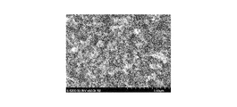
- Fig. 1A is a scanning electron microscopy (SEM) image of fluorinated carbon nanoparticles obtained according to an Example of the present invention.
- Fig. 1B is an SEM image of carbon black (Vulcan XC-72).
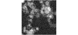
- Fig. 1C is a transmission electron microscopy (TEM) image of fluorinated carbon nanoparticles obtained in the Example.
- Fig. 1D is another TEM image of fluorinated carbon nanoparticles obtained in the Example.
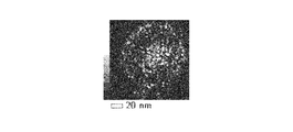
- Fig. 1E is an energy dispersive X-ray spectroscopy (EDX) elemental mapping of F on the region shown in Fig. 1D.
- Fig. 1F is an EDX elemental mapping of Na on the region shown in Fig. 1D.
- Fig. 1A is a scanning electron microscopy (SEM) image of fluorinated carbon nanoparticles obtained according to an Example of the present invention.
- Fig. 1B is an SEM image of carbon black (Vulcan XC
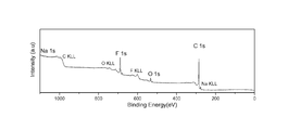
- FIG. 2A is a graph showing a wide-span X-ray photoelectron spectrum of the fluorinated carbon obtained in the Example.
- Fig. 2B is a graph showing an X-ray photoelectron spectrum in the range of electron binding energies from 280 to 295 eV and shows C 1s signal.
- Fig. 2C is a graph showing an X-ray photoelectron spectrum in the range of electron binding energies from 682 to 695 eV and shows F 1s signal.
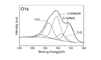
- Fig. 2D is a graph showing an X-ray photoelectron spectrum in the range of electron binding energies from 528 to 538 eV and shows O 1s signal.
- FIG. 2E is a graph showing an X-ray photoelectron spectrum in the range of electron binding energies from 1068 to 1077 eV and shows Na 1s signal.
- Fig. 3A is a graph showing Raman spectra of the fluorinated carbon, carbon black, and unfluorinated graphene foam.
- Fig. 3B is a graph showing X-ray diffraction spectra of the fluorinated carbon nanoparticles and unfluorinated graphene foam.
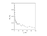
- Fig. 3C is a graph showing thermogravimetric analysis of the fluorinated carbon nanoparticles in air.
- Fig. 3D is a graph showing pore size distribution of the fluorinated carbon nanoparticles.
- Fig. 3A is a graph showing Raman spectra of the fluorinated carbon, carbon black, and unfluorinated graphene foam.
- Fig. 3B is a graph showing X-ray diffraction spectra of the fluorinated
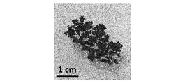
- FIG. 4A is a photograph of the powder of the fluorinated carbon nanoparticles floating on water after agitation.
- Fig. 4B is a photograph of the fluorinated carbon nanoparticles dispersed in ethanol.
- Fig. 4C is a photograph of fluorinated carbon nanoparticles printed onto filter paper.
- Fig. 4D is a photograph of fluorinated carbon nanoparticles printed onto nylon.
- Fig. 4E is a photograph of fluorinated carbon nanoparticles printed onto cotton.
- Fig. 4F is a photograph of fluorinated carbon nanoparticles sprayed onto silicon.
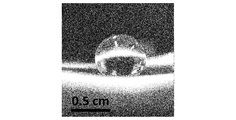
- Fig. 4G is a photograph of fluorinated carbon nanoparticles being subjected to water contact angle measurements on a Millipore membrane support.
- FIG. 5 is a transmission electron microscopy image of another embodiment of fluorinated carbon nanoparticles synthesized from a different fluorinated alcohol, namely C 8 F 17 C 2 H 4 OH.
- Fig. 6A is an SEM image of fluorinated carbon nanoparticles obtained in another example of the present invention.
- Fig. 6B is an SEM image of fluorinated carbon nanoparticles obtained in another example of the present invention.
- a preferred method for manufacturing fluorinated carbon at gram scale includes solvothermal reaction between fluorine-containing alcohol (which may be also referred to as fluorinated alcohol) and sodium metal.
- fluorine-containing alcohol which may be also referred to as fluorinated alcohol
- sodium metal which may be also referred to as sodium metal.
- the resulting fluorinated carbon displays superhydrophobic properties as well as oleophilic properties.
- fluorinated alcohol and sodium are reacted at elevated temperature (e.g. 180 degrees Celsius) in a sealed polytetrafluoroethylene (PTFE) reactor.
- the resulting alkoxide thermally decomposes due to the elevated temperature to form nanoscale carbon particles having a size of around 50 to 100 nm in diameter, which display a hollow-shell morphology, with significant fluorine content (the nanoscale carbon particles may also be referred to as fluorinated carbon nanoparticles in the following description).
- the fluorinated carbon nanoparticles are superhydrophobic (with a water contact angle of e.g. 168 degrees), oleophilic (with an n-hexadecane contact angle of e.g.
- the nanoparticle dispersion can be applied onto arbitrary substrates (e.g. paper, cloth, silicon) by printing, spraying or filtration, rendering them superhydrophobic.
- the fluorinated carbon nanoparticles obtained thereby are thermally stable.
- This method is a scalable method including the bottom-up fluorination of carbon powders, and could be applied in the mass production of superhydrophobic inks and paints, with potential applications in e.g. waterproofing, de-icing, self-cleaning surfaces, water management in electrochemical devices, and removing oil contamination from water.
- the reaction between the fluorinated alcohol and sodium is performed at a temperature sufficiently high to cause the thermal decomposition of the product (alkoxide) of the reaction to occur, and thus, the reaction between the fluorinated alcohol and sodium and the thermal decomposition of the alkoxide resulting from the reaction are performed substantially simultaneously. Therefore, the synthesis of halogenated carbon can be performed more simply and in a shorter period of time compared to a case where the reaction and the thermal decomposition are performed separately.
- fluorinated alcohol and sodium are reacted together to produce a fluorinated sodium alkoxide.
- the reaction between fluorinated alcohol and sodium is performed at a temperature (such as room temperature) that does not cause thermal decomposition of the fluorinated sodium alkoxide.
- the fluorinated sodium alkoxide is mixed with a powder (e.g. carbon black powder, inorganic particles, metal powder, metal oxide powder, etc.) or deposited onto a surface of a material (e.g. silicon, glass, metal oxide, metal, etc.) and then thermally annealed (or decomposed) into fluorinated carbon.
- a composite material is obtained in which the powder or the surface of the material is coated with a thin hydrophobic fluorinated carbon layer.
- the powder or the surface coated by the halogenated carbon can be obtained easily, so that the powder or the surface is given superhydrophobic properties.
- fluorinated alcohol is mixed with a powder (e.g. carbon black powder, inorganic particles, metal powder, metal oxide powder, etc.) or deposited onto a surface of a material (e.g. silicon, glass, metal oxide, metal, etc.) and then reacted with sodium, followed by thermal decomposition of the resulting alkoxide into fluorinated carbon.
- a powder e.g. carbon black powder, inorganic particles, metal powder, metal oxide powder, etc.
- a material e.g. silicon, glass, metal oxide, metal, etc.
- a composite material is obtained in which the powder or the surface of the material is coated with a thin hydrophobic fluorinated carbon layer. In this way, the powder or the surface coated by the halogenated carbon can be obtained easily, so that the powder or the surface is given superhydrophobic properties.
- Example The following example is intended to illustrate the invention, but is not to be construed as being limitations thereon. In the following example, all chemicals were used as received from suppliers, without further purification.
- C 6 F 13 CH 2 CH 2 OH was synthesized according to a procedure reported in Ref. [3] from the ethylenation of C 6 F 13 I followed by oxidation in a water / dimethylformamide (DMF) mixture. 5 ml (about 10 g) of C 6 F 13 CH 2 CH 2 OH was directly reacted with sodium metal (2 g, Sigma-Aldrich) in a sealed polytetrafluoroethylene (PTFE) melting pot (Flon Industry, Japan) at 180 degrees Celsius, and then cooled to room temperature.
- PTFE polytetrafluoroethylene
- the as-synthesized product was a highly flocculent dry black powder, dispersed with large white lumps and white powder.
- the white byproducts were confirmed to be sodium fluoride and sodium oxides by XPS.
- the product was dispersed in a 50/50 vol.% mixture of ethanol and deionized water, sonicated for 1 h, then vacuum filtered in order to remove the byproducts. After drying under vacuum, the final product mass was 1.75 g, corresponding to a yield of 17.5 wt%.
- the inventors have previously performed similar experiments reacting sodium with simple hydrogenated alcohol (ethanol / diethanolamine). [4-6] In those cases, sodium alkoxide powders were formed, and the material did not directly decompose into carbon. The sodium alkoxide powders were burned in air and decomposed to form defective graphene, and nitrogen-doped graphene macroporous open-cell foams, with a similar yield of around 15 wt%.
- SEM SEM (Fig. 1A) of the product manufactured by the manufacturing process in the Example (namely, fluorinated carbon) reveals that the product was comprised of interconnected spherical nanoscale particles (nanoparticles) with a diameter of around 50 to 100 nm. These nanoparticles clustered together, and were interspersed with micron-scale voids. This structure was highly uniform over a large scale and the shown images are representative of the whole sample. The nanoparticles are highly reminiscent of the structure of carbon black (e.g. Vulcan XC72 shown in Fig. 1B), although with a slightly larger particle size.
- carbon black e.g. Vulcan XC72 shown in Fig. 1B
- EDX elemental analysis on the region shown in Fig. 1D gives a carbon content of 94.9 at%, a fluorine content of 2.63 at%, and a sodium content of 2.43 at%.
- EDX elemental mapping suggests that the material inside the shell is sodium fluoride (NaF), whilst the shell itself comprised carbon and fluorine.
- Selective elemental mapping of the dense inner material (or core) reveals approximately equal proportions of Na (5.76 at%) and F (5.21 at%), confirming the presence of NaF.
- the C 1s sprectra of fluorinated carbons are generally decovoluted into separate signals corresponding to CF (about 289.6 eV), CF 2 (about 291.5 eV) and CF 3 (about 294.0 eV) covalent bonds, and semi-ionic bonds (about 286.5 eV) (as well as sp 2 carbon at about 284.5 eV, and carbon-oxygen bonds at about 285.5 eV).
- F 1s spectra are generally only deconvoluted into covalent (about 688.3 eV), semi-ionic (about 686.5 eV), and ionic (about 684 eV) bonds. All of these peak assignments depend somewhat upon the structure of the carbon skeleton. Additionally, due to the electical resistivity of fluorinated carbons, some charging effects are also expected, shifting the spectra in the postive binding energy direction.
- the XPS wide-scan reveals the presence of carbon (75.2 at%), oxygen (7.2 at%), fluorine (17.1 at%), and sodium (about 0.5 at%) in a sample of the fluorinated carbon obtained in the Example (Fig 2A).
- XPS is a much more surface-sensitive technique probing only a few nanometers in depth, and is therefore unable to detect the interior of the nanoparticles.
- XPS is highly sensitive to adsorbed moisture, whilst it is difficult to deconvolute oxygen and carbon using the EDX technoique.
- the C 1s signal is shown in Fig. 2B. This is deconvoluted into carbon-carbon bonds at 284.5 eV, carbon-oxygen bonds at about 285.5 eV, semi-ionic CF / epoxy groups at about 286.5 eV, covalent CF at 289.6 eV. There are various small peaks at higher energy which may correspond to small proportions of CF 2 at 291.5 eV, or CF 3 at 294.0 eV, or C 1s shake-up.
- the F 1s spectrum (Fig. 2C) is centered at 688 eV, attributed to a single peak corresponding to covalent CF bonds. There are only very small shoulders, suggesting that the majority of F-bonding in this material is covalent.
- the O 1s spectrum (Fig.
- Raman spectroscopy was used to probe the carbon structure of the fluorinated carbon obtained in the Example, and the result was compared with the result of Raman spectroscopy of the carbon black and the unfluorinated ethanol-derived carbon (Fig. 3A).
- the Raman peaks observed here are associated only with the carbon structure.
- the energy of the laser was below that of the energy gap of graphite fluoride and therefore Raman signals were not activated by fluorine inclusion.
- the D-peak at 1344 cm -1 was prominent, and the background-corrected, normalized I D /I G ratio (1.3) was higher than that of carbon black (1.0) and the ethanol-derived carbon (1.1), indicating that the fluorinated carbon nanoparticles are more defective at the atomic scale, probably due to disruption of the sp 2 carbon network by sp 3 covalently bonded fluorine atoms.
- the G-peak (1591 cm -1 ) was similar for all the samples.
- the peak at 18 degrees (0.50 nm) corresponds to CF x (002), confirming that fluorination of the carbon was successful.
- An additional peak appearing at 42 degrees (0.20 nm) has also been attributed to CF x (100). Peaks at around 39 degrees (0.23 nm) and 56 degrees (0.16 nm) correspond to NaF and are in agreement with the EDX and XPS results.
- the thermal stability was investigated by TGA in air (20 ml/min, Fig. 3C).
- the material was relatively stable up to around 500 degrees Celsius in air, where the material started steadily decomposing, endothermically, until nothing was left. This suggests that the actual NaF content was extremely low.
- the specific surface area and porosity of the fluorinated carbon obtained in the Example were investigated using BET nitrogen adsorption.
- the measured specific surface area was quite low at just 29 m 2 /g, about an order of magnitude lower than that of Vulcan (measured under the same conditions to be 239 m 2 /g). This may be due in part to the large nanoparticle size of the fluorinated carbon compared with carbon black. Additionally, fluorination is known to reduce the micropore volume. Pore-size distribution plots (Fig. 3D) show a sharp peak in pore sizes below 10 nm in radius.
- the ink formed of the dispersion of the fluorinated carbon nanoparticles was vacuum filtered onto: filter paper; nylon; and cotton (Figs. 4C-4E).
- the ink was also sprayed onto silicon (Fig 4F). As seen in Figs. 4C-4F, all of the surfaces of these materials were rendered superhydrophobic after treatment with the fluorinated carbon nanoparticles.
- the superhydrophobic properties of the fluorinated carbon nanoparticles obtained in the Example were quantitatively assessed on PTFE membranes using dynamic contact angle measurements.
- the water contact angle was measured to be 168 degrees, which is significantly high, and confirms the superhydrophobic nature of this material (Fig 4G).
- the interaction between the fluorinated carbon nanoparticles and the substrate was weak, causing the fluorinated carbon nanoparticles to easily become detached.
- the interaction with n-hexadecane was also investigated, and the contact angle was 0 degrees, showing that the fluorinated carbon nanoparticles are oleophilic, opening up potential applications in e.g. oil separation from water.
- the water contact angle for the non-fluorinated, ethanol-derived carbon was 0 degrees for both water and n-hexadecane, displaying both hydrophilic and oleophilic properties, and confirming that fluorination has a significant impact on the surface properties of the resulting carbon.
- Fig. 5 is a transmission electron microscopy image of fluorinated carbon synthesized using C 8 F 17 C 2 H 4 OH as fluorinated alcohol. As seen in Fig. 5, this fluorinated carbon also includes nanoparticles (the particle size being around 200 nm in diameter) that display a hollow-shell structure, similarly to the fluorinated carbon shown in Figs. 1A and 1C.
- fluorinated alcohol was used in the above embodiments, other halogenated alcohols (for example but not limited to chloroethanol, bromoethanol, tribromoethanol, or trichloroethanol) may be used instead or in addition.
- halogenated alcohols for example but not limited to chloroethanol, bromoethanol, tribromoethanol, or trichloroethanol
- the metal to react with the halogenated alcohol to obtain halogenated carbon does not have to be sodium, and other alkali or alkali earth metals (such as lithium, potassium, calcium and so on) may also be used.
- Fig. 6A is an SEM image of fluorinated carbon obtained by reacting trifluoroethanol with NaH in diethyl ether solvent, followed by thermal decomposition at 600 degrees Celsius under flowing nitrogen.
- Fig. 6B is an SEM image of fluorinated carbon obtained by reacting pentafluoropropanol with NaH, followed by the same thermal decomposition process. As seen in Figs.
- the obtained fluorinated carbon was constituted of fluorinated carbon nanoparticles having a hollow shell structure (the particle size being around 30 to 100 nm in diameter), and demonstrated superhydrophobic and oleophilic properties.
- Example ethanol was used as a liquid dispersion medium in which the fluorinated (more generally, halogenated) carbon nanoparticles are dispersed
- other liquid dispersion media for example but not limited to methanol, n-propanol, isopropanol, n-butanol, acetone, dimethylformamide, benzene, toluene, chloroform, acetonitrile
- methanol n-propanol
- isopropanol isopropanol
- n-butanol acetone
- dimethylformamide dimethylformamide
- benzene toluene
- chloroform acetonitrile
Landscapes
- Chemical & Material Sciences (AREA)
- Organic Chemistry (AREA)
- Inorganic Chemistry (AREA)
- Carbon And Carbon Compounds (AREA)
- Pigments, Carbon Blacks, Or Wood Stains (AREA)
Abstract
Provided is halogenated carbon including nanoscale particles having a hollow shell structure, shells of the nanoparticles including carbon and halogen. The halogen may include fluorine. The halogenated carbon having this structure demonstrates hydrophobic properties and oleophilic properties. A method for manufacturing such halogenated carbon includes reaction between alkali metal, alkali earth metal or hydride thereof and halogenated alcohol, followed by thermal decomposition of a product of the reaction.
Description
The present invention relates to halogenated carbon and a method for manufacturing halogenated carbon. Particularly, the present invention relates to halogenated carbon with hydrophobic and oleophilic properties and a method for manufacturing such halogenated carbon.
Halogenation, such as fluorination, is an effective method to tailor the properties of a wide range of carbon materials. Graphite fluoride is the most well established covalently bonded fluorocarbon (fluorinated carbon), formed by a harsh fluorination of graphite. It has several interesting properties; it is electrically insulating, is thermally conductive, has low shear strength, and has a wide band gap. Graphite fluoride is widely used as an electrode in lithium batteries, as a solid lubricant, and as an additive for weather resistant paint.
Fluorination of carbon-based materials, such as carbon blacks; carbon fibers; single wall carbon nanotubes; multiwall carbon nanotubes; and graphene, has been explored extensively in recent decades. There are several main methods for the preparation of fluorinated carbons; direct fluorination in F2 gas at elevated temperature, sometimes in the presence of HF or IF5 (at 150 to 600 degrees Celsius); radio-frequency plasma treatment in CF4 gas; chemical vapor deposition from perfluorohexane at 100 to 500 degrees Celsius, chemical vapor deposition in CF4 plasma at room temperature; decomposition of xenon difluoride (XeF2); mechanical exfoliation of graphite fluoride; arc discharge between graphite fluoride-containing graphite rods; coating with fluorinated silane; reduction of graphene oxide in HF; and the use of perfluoropolyether peroxide. In addition, coating e.g. carbon nanotubes forests in polytetrafluoroethylene (PTFE) can result in superhydrophobic "fluorinated" carbons. Of these methods, direct fluorination in F2 or XeF2 is by far the most common.
Fluorination of nanostructured carbons generally results in modification of the electronic properties. For example, fluorinated graphene has been used as a transistor, and colossal negative magnetoresistance has been observed. The optical properties can also be drastically modified; fluorinated carbons can be grey, white, or even transparent due to the induced wide band-gap of around 3.8 eV. [1, 2]. Fluorographene has also been reported to be magnetic, and has improved electron field emission properties.
In particular, the wettability of carbons can be modified by fluorination. Fluorinated carbons often display superhydrophobic properties due to low surface energy, and appropriate microscopic surface roughness. Superhydrophobic surfaces have very weak interaction with water, resulting in extremely high water contact angles (WCA) (greater than e.g. 150 degrees) and low water roll-off / tilt angle (TA) (less than e.g. 30 degrees).
Superhydrophobic materials are industrially useful in such applications as e.g. self-cleaning surfaces; fluidic drag reduction; enhancing water supporting force in membranes; bio-surfaces; corrosion prevention; preventing snow / ice accumulation; enhancing buoyancy; flow management in microfluidic devices; and oil spill cleaning. In electrochemical devices such as polymer electrolyte membrane fuel cells (PEMFCs) (may also be referred to as polymer electrolyte fuel cells (PEFCs), water electrolyzers, and batteries, water management is of great importance to prevent flooding; superhydrophobic materials can be of great help in this case.
With regard to fluorination of carbon material, JP S58-176110A discloses a method for manufacturing fluorinated graphite having a structure expressed by (CF)n or (C2F)n. The method disclosed in this publication is characterized by using fine hollow particles of carbon as the carbon material to be fluorinated to improve the reaction efficiency and achieve a high yield. The fine hollow particles of carbon used in this method may be prepared by spraying spherical phenol resin into small droplets while heating them to foam and cure at the same time and thereafter carbonizing them by calcination, or by suspending petroleum pitch in a low-boiling temperature organic solvent or water, heating it to foam and then carbonizing it by calcination. The carbon particles obtained thereby are 100% carbon and have 5-1000 micron diameter, 0.05- 0.4 g/cm3 bulk specific gravity, and 0.5-50 micron wall thickness. It is also described in JP S58-176110A that, though the particle diameter, wall thickness, bulk specific gravity, etc. may be controlled freely by changing manufacturing conditions, carbon particles of about 20-500 micron diameter are industrially produced, and the carbon particles in this range are sufficient for the invention disclosed in JP S58-176110A.
The fine hollow carbon particles are caused to react with fluorine at the reaction temperature of 350-600 degrees Celsius and with a fluorine partial pressure of 100-760 mmHg. JP S58-176110A describes that the (CF)n or (C2F)n fluorinated graphite obtained thereby can be said to be fine hollow particles of fluorinated graphite and may be used as fine hollow particles which are relatively light in weight and have a heat insulating property, water repellent property, oil repellent property, lubricating property and so on. However, there is no description in JP S58-176110A that the obtained fine hollow particles of fluorinated graphite have both hydrophobic and oleophilic properties. Lack of oleophilic properties may restrict the use of the fluorinated graphite.
Thus, there is a demand for halogenated carbon (such as fluorinated carbon) having hydrophobic and oleophilic properties and a method for manufacturing halogenated carbon in a simple manner.
In view of such a need in this field of technology, a primary object of the present invention is to provide halogenated carbon having hydrophobic and oleophilic properties and a method for manufacturing such halogenated carbon in a simple manner.
A second object of the present invention is to provide a material coated by a thin layer of halogenated carbon and a method for coating a material with a thin layer of halogenated carbon.
To achieve such objects, according to one aspect of the present invention, there is provided halogenated carbon including nanoscale particles having a hollow shell structure, shells of the nanoscale particles including carbon and halogen. The halogen preferably includes fluorine. The nanoscale particles have a diameter greater than 10 nm and less than 1000 nm, preferably from around 30 to 200 nm, and more preferably from around 50 to 100 nm.
The halogenated carbon having the above structure demonstrates hydrophobic and oleophilic properties. Particularly, the feature that the hollow particles constituting the halogenated carbon include nanoscale particles (nanoparticles) is considered to contribute to demonstrating excellent hydrophobic (superhydrophobic) and oleophilic properties.
In a preferred embodiment, the halogenated carbon is dispersed in a liquid dispersion medium, which preferably is ethanol. The halogenated carbon dispersed in a liquid dispersion medium can be applied onto arbitrary substrates by printing, spraying or filtration (e.g. paper, cloth, silicon), rendering them superhydrophobic easily. Further, as the halogenated carbon includes nanoscale particles, the thickness of the membrane of halogenated carbon formed by applying the halogenated carbon dispersion onto the substrate can be very small, and this makes it easier to form a substantially transparent halogenated carbon membrane that does not significantly change the perceived color of the surface of the substrate.
In another preferred embodiment, the halogenated carbon coats powder or a surface of another material. This renders the powder or the surface coated by the halogenated carbon superhydrophobic.
According to another aspect of the present invention, there is provided a method for manufacturing halogenated carbon, including reaction between alkali metal, alkali earth metal or hydride thereof and halogenated alcohol, followed by thermal decomposition of a product of the reaction. The halogenated alcohol preferably includes fluorinated alcohol and the alkali or alkali earth metal preferably includes sodium. According to this method, halogenated carbon can be manufactured in a simple manner.
In a preferred embodiment, the reaction between the alkali metal, alkali earth metal or hydride thereof and the halogenated alcohol is performed at a temperature sufficiently high to cause the thermal decomposition to occur. In this way, the reaction between the alkali metal, alkali earth metal or hydride thereof and the halogenated alcohol and the thermal decomposition of the product of the reaction are performed substantially simultaneously, and this allows the synthesis of halogenated carbon to be performed more simply and in a shorter period of time.
Preferably, the method further includes dispersing the halogenated carbon obtained by the thermal decomposition in a liquid dispersion medium, which preferably includes ethanol. The halogenated carbon dispersed in a liquid dispersion medium can be applied onto arbitrary substrates (e.g. paper, cloth, silicon) by printing, spraying or filtration, rendering them superhydrophobic easily.
In another preferred embodiment, the product of the reaction between the alkali metal, alkali earth metal or hydride thereof and the halogenated alcohol is mixed with a powder or coated on a surface of another material before the thermal decomposition. This allows the powder or the surface to be coated by the halogenated carbon easily, rendering the powder or the surface superhydrophobic.
In yet another preferred embodiment, the halogenated alcohol is mixed with a powder or coated on a surface of another material before the halogenated alcohol is reacted with the alkali metal, alkali earth metal or hydride thereof. This allows the powder or the surface to be coated by the halogenated carbon easily, rendering the powder or the surface superhydrophobic.
According to yet another aspect of the present invention, there is provided halogenated carbon produced by reaction between alkali metal, alkali earth metal or hydride thereof and halogenated alcohol, followed by thermal decomposition of a product of the reaction. The halogenated alcohol preferably includes fluorinated alcohol and the alkali or alkali earth metal preferably includes sodium. The halogenated carbon produced thereby demonstrates hydrophobic and oleophilic properties.
As mentioned above, the halogenated carbon may be dispersed in a liquid dispersion medium, which preferably is ethanol, or may coat powder or a surface of another material.
In the following, embodiments of the present invention will be described with reference to the drawings.
(First Embodiment)
In the first embodiment of the present invention, a preferred method for manufacturing fluorinated carbon at gram scale is provided. This preferred method includes solvothermal reaction between fluorine-containing alcohol (which may be also referred to as fluorinated alcohol) and sodium metal. The resulting fluorinated carbon displays superhydrophobic properties as well as oleophilic properties.
In the first embodiment of the present invention, a preferred method for manufacturing fluorinated carbon at gram scale is provided. This preferred method includes solvothermal reaction between fluorine-containing alcohol (which may be also referred to as fluorinated alcohol) and sodium metal. The resulting fluorinated carbon displays superhydrophobic properties as well as oleophilic properties.
In the first embodiment, fluorinated alcohol and sodium are reacted at elevated temperature (e.g. 180 degrees Celsius) in a sealed polytetrafluoroethylene (PTFE) reactor. The resulting alkoxide thermally decomposes due to the elevated temperature to form nanoscale carbon particles having a size of around 50 to 100 nm in diameter, which display a hollow-shell morphology, with significant fluorine content (the nanoscale carbon particles may also be referred to as fluorinated carbon nanoparticles in the following description). The fluorinated carbon nanoparticles are superhydrophobic (with a water contact angle of e.g. 168 degrees), oleophilic (with an n-hexadecane contact angle of e.g. 0 degrees), and disperses easily in ethanol. The nanoparticle dispersion can be applied onto arbitrary substrates (e.g. paper, cloth, silicon) by printing, spraying or filtration, rendering them superhydrophobic. The fluorinated carbon nanoparticles obtained thereby are thermally stable.
This method is a scalable method including the bottom-up fluorination of carbon powders, and could be applied in the mass production of superhydrophobic inks and paints, with potential applications in e.g. waterproofing, de-icing, self-cleaning surfaces, water management in electrochemical devices, and removing oil contamination from water.
In the first embodiment, the reaction between the fluorinated alcohol and sodium is performed at a temperature sufficiently high to cause the thermal decomposition of the product (alkoxide) of the reaction to occur, and thus, the reaction between the fluorinated alcohol and sodium and the thermal decomposition of the alkoxide resulting from the reaction are performed substantially simultaneously. Therefore, the synthesis of halogenated carbon can be performed more simply and in a shorter period of time compared to a case where the reaction and the thermal decomposition are performed separately.
(Second Embodiment)
In the second embodiment of the present invention, fluorinated alcohol and sodium are reacted together to produce a fluorinated sodium alkoxide. In the second embodiment, the reaction between fluorinated alcohol and sodium is performed at a temperature (such as room temperature) that does not cause thermal decomposition of the fluorinated sodium alkoxide. The fluorinated sodium alkoxide is mixed with a powder (e.g. carbon black powder, inorganic particles, metal powder, metal oxide powder, etc.) or deposited onto a surface of a material (e.g. silicon, glass, metal oxide, metal, etc.) and then thermally annealed (or decomposed) into fluorinated carbon. By washing it in a 50/50% water ethanol mix, for example, a composite material is obtained in which the powder or the surface of the material is coated with a thin hydrophobic fluorinated carbon layer. In this way, the powder or the surface coated by the halogenated carbon can be obtained easily, so that the powder or the surface is given superhydrophobic properties.
In the second embodiment of the present invention, fluorinated alcohol and sodium are reacted together to produce a fluorinated sodium alkoxide. In the second embodiment, the reaction between fluorinated alcohol and sodium is performed at a temperature (such as room temperature) that does not cause thermal decomposition of the fluorinated sodium alkoxide. The fluorinated sodium alkoxide is mixed with a powder (e.g. carbon black powder, inorganic particles, metal powder, metal oxide powder, etc.) or deposited onto a surface of a material (e.g. silicon, glass, metal oxide, metal, etc.) and then thermally annealed (or decomposed) into fluorinated carbon. By washing it in a 50/50% water ethanol mix, for example, a composite material is obtained in which the powder or the surface of the material is coated with a thin hydrophobic fluorinated carbon layer. In this way, the powder or the surface coated by the halogenated carbon can be obtained easily, so that the powder or the surface is given superhydrophobic properties.
(Third Embodiment)
In the second embodiment of the present invention, fluorinated alcohol is mixed with a powder (e.g. carbon black powder, inorganic particles, metal powder, metal oxide powder, etc.) or deposited onto a surface of a material (e.g. silicon, glass, metal oxide, metal, etc.) and then reacted with sodium, followed by thermal decomposition of the resulting alkoxide into fluorinated carbon. By washing it in a 50/50% water ethanol mix, for example, a composite material is obtained in which the powder or the surface of the material is coated with a thin hydrophobic fluorinated carbon layer. In this way, the powder or the surface coated by the halogenated carbon can be obtained easily, so that the powder or the surface is given superhydrophobic properties.
In the second embodiment of the present invention, fluorinated alcohol is mixed with a powder (e.g. carbon black powder, inorganic particles, metal powder, metal oxide powder, etc.) or deposited onto a surface of a material (e.g. silicon, glass, metal oxide, metal, etc.) and then reacted with sodium, followed by thermal decomposition of the resulting alkoxide into fluorinated carbon. By washing it in a 50/50% water ethanol mix, for example, a composite material is obtained in which the powder or the surface of the material is coated with a thin hydrophobic fluorinated carbon layer. In this way, the powder or the surface coated by the halogenated carbon can be obtained easily, so that the powder or the surface is given superhydrophobic properties.
(Example)
The following example is intended to illustrate the invention, but is not to be construed as being limitations thereon. In the following example, all chemicals were used as received from suppliers, without further purification.
The following example is intended to illustrate the invention, but is not to be construed as being limitations thereon. In the following example, all chemicals were used as received from suppliers, without further purification.
As halogenated (fluorinated) alcohol, C6F13CH2CH2OH was synthesized according to a procedure reported in Ref. [3] from the ethylenation of C6F13I followed by oxidation in a water / dimethylformamide (DMF) mixture. 5 ml (about 10 g) of C6F13CH2CH2OH was directly reacted with sodium metal (2 g, Sigma-Aldrich) in a sealed polytetrafluoroethylene (PTFE) melting pot (Flon Industry, Japan) at 180 degrees Celsius, and then cooled to room temperature.
Scanning electron microscopy (SEM, S-5200, Hitachi, Japan); transmission electron microscopy (TEM) coupled with energy-dispersive X-ray spectroscopy (EDX) mapping (JEM-ARM200F, JEOL, Japan); Brunauer-Emmett-Teller (BET) theory nitrogen adsorption surface area analysis (Belsorp Mini II-VS, Bel Japan, Inc.); thermo-gravimetric analysis (TGA, TG 8120, Rigaku Corp., Japan); Raman spectroscopy (DM2500M, Renishaw, UK, using an argon-ion laser at 532 nm); X-ray diffraction (XRD, RINT Ultima III, Rigaku, Japan, Cu K alpha-radiation, wavelength = 1.54 angstrom); X-ray photoelectron spectroscopy (XPS, ESCA-3400, Kratos Analytical Ltd., UK); and dynamic contact angle measurements were used to characterize the material.
The as-synthesized product was a highly flocculent dry black powder, dispersed with large white lumps and white powder. The white byproducts were confirmed to be sodium fluoride and sodium oxides by XPS. The product was dispersed in a 50/50 vol.% mixture of ethanol and deionized water, sonicated for 1 h, then vacuum filtered in order to remove the byproducts. After drying under vacuum, the final product mass was 1.75 g, corresponding to a yield of 17.5 wt%. A non-stoichiometric reaction scheme detailing the probable products of the decomposition is presented below:
C6F13CH2CH2OH + Na ---[180 degrees Celsius, decomposition]---> CFx + H2 + HF + NaF + NaO(H)
C6F13CH2CH2OH + Na ---[180 degrees Celsius, decomposition]---> CFx + H2 + HF + NaF + NaO(H)
The inventors have previously performed similar experiments reacting sodium with simple hydrogenated alcohol (ethanol / diethanolamine). [4-6] In those cases, sodium alkoxide powders were formed, and the material did not directly decompose into carbon. The sodium alkoxide powders were burned in air and decomposed to form defective graphene, and nitrogen-doped graphene macroporous open-cell foams, with a similar yield of around 15 wt%.
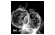
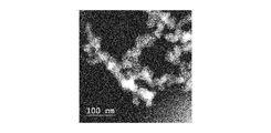
On the other hand, SEM (Fig. 1A) of the product manufactured by the manufacturing process in the Example (namely, fluorinated carbon) reveals that the product was comprised of interconnected spherical nanoscale particles (nanoparticles) with a diameter of around 50 to 100 nm. These nanoparticles clustered together, and were interspersed with micron-scale voids. This structure was highly uniform over a large scale and the shown images are representative of the whole sample. The nanoparticles are highly reminiscent of the structure of carbon black (e.g. Vulcan XC72 shown in Fig. 1B), although with a slightly larger particle size. In contrast, it is known that in the case where ethanol is used in place of the fluorinated alcohol, a completely different structure is produced after decomposition; an open-cell defective graphene foam, as explored extensively in our previous studies. [4-6] Further, TEM images (Figs. 1C and 1D) of the fluorinated carbon obtained in the Example immediately reveal that these nanoparticles had a hollow shell morphology. The thickness of the shell walls was around 10 nm, and there was a relatively electron dense spheroid (may be referred to as a core) located inside many of them.
EDX elemental analysis on the region shown in Fig. 1D gives a carbon content of 94.9 at%, a fluorine content of 2.63 at%, and a sodium content of 2.43 at%. EDX elemental mapping (Figs. 1E and 1F) suggests that the material inside the shell is sodium fluoride (NaF), whilst the shell itself comprised carbon and fluorine. Selective elemental mapping of the dense inner material (or core) reveals approximately equal proportions of Na (5.76 at%) and F (5.21 at%), confirming the presence of NaF. Selective elemental analysis of only the shell region (avoiding the NaF particle in the center) gives a carbon content of 96.64 at%, a fluorine content of 2.39 at%, and a sodium content of 0.97 at%, which are different from those obtained by elemental analysis on the region shown in Fig. 1D. This difference confirms that fluorine was doped into the walls of the nanoparticles but little sodium was doped into the walls of the nanoparticles. In comparison, unfluorinated carbon derived from ethanol and sodium was measured to have a carbon content of 96.4 at% and an oxygen content of 3.6 at%.
XPS studies were carried out on the fluorinated carbons obtained in the Example, indicating several main bonding types (Figs. 2A-2E). The C 1s sprectra of fluorinated carbons are generally decovoluted into separate signals corresponding to CF (about 289.6 eV), CF2 (about 291.5 eV) and CF3 (about 294.0 eV) covalent bonds, and semi-ionic bonds (about 286.5 eV) (as well as sp2 carbon at about 284.5 eV, and carbon-oxygen bonds at about 285.5 eV). F 1s spectra are generally only deconvoluted into covalent (about 688.3 eV), semi-ionic (about 686.5 eV), and ionic (about 684 eV) bonds. All of these peak assignments depend somewhat upon the structure of the carbon skeleton. Additionally, due to the electical resistivity of fluorinated carbons, some charging effects are also expected, shifting the spectra in the postive binding energy direction.
In this work, the XPS wide-scan reveals the presence of carbon (75.2 at%), oxygen (7.2 at%), fluorine (17.1 at%), and sodium (about 0.5 at%) in a sample of the fluorinated carbon obtained in the Example (Fig 2A). There is a significant difference between these results and the EDX results, since XPS is a much more surface-sensitive technique probing only a few nanometers in depth, and is therefore unable to detect the interior of the nanoparticles. Additionally, XPS is highly sensitive to adsorbed moisture, whilst it is difficult to deconvolute oxygen and carbon using the EDX technoique. There are several smaller peaks in the wide-scan XPS corresponding to the C KLL, O KLL, F KLL and Na KLL. The sodium content is very low, as most of the NaF is encapsulated within the carbon shell or contained in the core within the shell (as observed in EDX mapping) and therefore cannot be detected by XPS. These XPS results suggest that the composition of the fluorinated carbon (contained in the shell) is approximately C4F.
The C 1s signal is shown in Fig. 2B. This is deconvoluted into carbon-carbon bonds at 284.5 eV, carbon-oxygen bonds at about 285.5 eV, semi-ionic CF / epoxy groups at about 286.5 eV, covalent CF at 289.6 eV. There are various small peaks at higher energy which may correspond to small proportions of CF2 at 291.5 eV, or CF3 at 294.0 eV, or C 1s shake-up. The F 1s spectrum (Fig. 2C) is centered at 688 eV, attributed to a single peak corresponding to covalent CF bonds. There are only very small shoulders, suggesting that the majority of F-bonding in this material is covalent. The O 1s spectrum (Fig. 2D) is deconvoluted into four main peaks at: 530.0 eV (C=O / NaO), 531.4 eV (C-O), 532.3 eV (O-H / NaOH), and 533.5 eV (adsorbed H2O). The Na 1s signal (Fig. 2E) is deconvoluted into peaks corresponding to NaO (1073.3 eV) and NaF (1071.3 eV).
Raman spectroscopy was used to probe the carbon structure of the fluorinated carbon obtained in the Example, and the result was compared with the result of Raman spectroscopy of the carbon black and the unfluorinated ethanol-derived carbon (Fig. 3A). The Raman peaks observed here are associated only with the carbon structure. The energy of the laser was below that of the energy gap of graphite fluoride and therefore Raman signals were not activated by fluorine inclusion. The D-peak at 1344 cm-1 was prominent, and the background-corrected, normalized ID/IG ratio (1.3) was higher than that of carbon black (1.0) and the ethanol-derived carbon (1.1), indicating that the fluorinated carbon nanoparticles are more defective at the atomic scale, probably due to disruption of the sp2 carbon network by sp3 covalently bonded fluorine atoms. The G-peak (1591 cm-1) was similar for all the samples.
Both the fluorinated and unfluorinated carbons were characterized using XRD (Fig. 3B). In the unfluorinated sample, the only peaks in the spectrum correspond to broad 002 (about 0.40 nm lattice spacing) and 100 (about 0.20 nm lattice spacing) crystal planes, suggesting that the material is highly defective, with little long-range order. The fluorinated carbon nanoparticles displayed similar signals corresponding to carbon 002 and 100, but several sharp peaks were overlaid with this defective carbon signal. A sharp double peak at 26 degrees (0.34 nm spacing) suggests the presence of some highly crystalline carbon in the fluorinated sample. The peak at 18 degrees (0.50 nm) corresponds to CFx (002), confirming that fluorination of the carbon was successful. An additional peak appearing at 42 degrees (0.20 nm) has also been attributed to CFx (100). Peaks at around 39 degrees (0.23 nm) and 56 degrees (0.16 nm) correspond to NaF and are in agreement with the EDX and XPS results.
The thermal stability was investigated by TGA in air (20 ml/min, Fig. 3C). The material was relatively stable up to around 500 degrees Celsius in air, where the material started steadily decomposing, endothermically, until nothing was left. This suggests that the actual NaF content was extremely low.
The specific surface area and porosity of the fluorinated carbon obtained in the Example were investigated using BET nitrogen adsorption. The measured specific surface area was quite low at just 29 m2/g, about an order of magnitude lower than that of Vulcan (measured under the same conditions to be 239 m2/g). This may be due in part to the large nanoparticle size of the fluorinated carbon compared with carbon black. Additionally, fluorination is known to reduce the micropore volume. Pore-size distribution plots (Fig. 3D) show a sharp peak in pore sizes below 10 nm in radius.
Many fluorinated carbons are superhydrophobic. Therefore, the interaction of the fluorinated carbon nanoparticles obtained in the Example with water was investigated (Figs. 4A-4G). Initially, a sample of the powder of the fluorinated carbon nanoparticles was added to deionized water and vigorously shaken. No wetting or dispersion of the sample occurred, and the powder remained floating on the surface of the water, even after several weeks (Fig. 4A). Conversely, the powder forms a stable dispersion in ethanol (2.5 mg/ml, Fig 4B), allowing solution processing of the fluorinated carbon nanoparticles by printing, spraying, or filtration onto various substrates. As examples, the ink formed of the dispersion of the fluorinated carbon nanoparticles was vacuum filtered onto: filter paper; nylon; and cotton (Figs. 4C-4E). The ink was also sprayed onto silicon (Fig 4F). As seen in Figs. 4C-4F, all of the surfaces of these materials were rendered superhydrophobic after treatment with the fluorinated carbon nanoparticles.
The superhydrophobic properties of the fluorinated carbon nanoparticles obtained in the Example were quantitatively assessed on PTFE membranes using dynamic contact angle measurements. The water contact angle was measured to be 168 degrees, which is significantly high, and confirms the superhydrophobic nature of this material (Fig 4G). However, the interaction between the fluorinated carbon nanoparticles and the substrate was weak, causing the fluorinated carbon nanoparticles to easily become detached. The interaction with n-hexadecane was also investigated, and the contact angle was 0 degrees, showing that the fluorinated carbon nanoparticles are oleophilic, opening up potential applications in e.g. oil separation from water.
In comparison, the water contact angle for the non-fluorinated, ethanol-derived carbon was 0 degrees for both water and n-hexadecane, displaying both hydrophilic and oleophilic properties, and confirming that fluorination has a significant impact on the surface properties of the resulting carbon.
The present invention has been described above in terms of preferred embodiments thereof, but it is obvious to a person skilled in the art that the present invention is not limited to the embodiments and various alterations and modifications are possible without departing from the scope of the present invention.
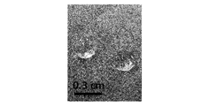
For instance, though C6F13CH2CH2OH was used as fluorinated alcohol in the above example, other fluorinated alcohols, such as C8F17C2H4OH or trifluoroethanol, may be used instead or in addition. Fig. 5 is a transmission electron microscopy image of fluorinated carbon synthesized using C8F17C2H4OH as fluorinated alcohol. As seen in Fig. 5, this fluorinated carbon also includes nanoparticles (the particle size being around 200 nm in diameter) that display a hollow-shell structure, similarly to the fluorinated carbon shown in Figs. 1A and 1C.
Further, though fluorinated alcohol was used in the above embodiments, other halogenated alcohols (for example but not limited to chloroethanol, bromoethanol, tribromoethanol, or trichloroethanol) may be used instead or in addition.
Yet further, the metal to react with the halogenated alcohol to obtain halogenated carbon does not have to be sodium, and other alkali or alkali earth metals (such as lithium, potassium, calcium and so on) may also be used.
Further, hydrides of alkali or alkali earth metals (such as NaH) may also be used instead of or in addition to sodium. Fig. 6A is an SEM image of fluorinated carbon obtained by reacting trifluoroethanol with NaH in diethyl ether solvent, followed by thermal decomposition at 600 degrees Celsius under flowing nitrogen. Fig. 6B is an SEM image of fluorinated carbon obtained by reacting pentafluoropropanol with NaH, followed by the same thermal decomposition process. As seen in Figs. 6A and 6B, in these examples also, the obtained fluorinated carbon was constituted of fluorinated carbon nanoparticles having a hollow shell structure (the particle size being around 30 to 100 nm in diameter), and demonstrated superhydrophobic and oleophilic properties.
Further, though in the above Example ethanol was used as a liquid dispersion medium in which the fluorinated (more generally, halogenated) carbon nanoparticles are dispersed, other liquid dispersion media (for example but not limited to methanol, n-propanol, isopropanol, n-butanol, acetone, dimethylformamide, benzene, toluene, chloroform, acetonitrile) may be used instead or in addition.
(References)
[1] F. Withers, M. Dubois, and A. K. Savchenko, Phys. Rev. B 82, 073403 (2010).
[2] K.-J. Jeon, Z. Lee, E. Pollak, L. Moreschini, A. Bostwick, C.-M. Park, R. Mendelsberg, V. Radmilovic, R. Kostecki, T. J. Richardson, and E. Rotenberg, ACS Nano 5, 1042 (2011).
[3] G. Kostov, M. Holan, B. Ameduri, and M. H. Hung, Macromolecules 45, 7375 (2012).
[4] S. M. Lyth, Y. Nabae, N. M. Islam, T. Hayakawa, S. Kuroki, M. Kakimoto, and S. Miyata, E-Journal Surf. Sci. Nanotechnol. 10, 29 (2012).
[5] S. M. Lyth, H. Shao, J. Liu, K. Sasaki, Int. J. Hydrogen Energy 39, 376 (2014).
[6] J. Liu, D. Takeshi, D. Orejon, K. Sasaki, and S. M. Lyth, J. Electrochem. Soc. 161, F544 (2014).
[1] F. Withers, M. Dubois, and A. K. Savchenko, Phys. Rev. B 82, 073403 (2010).
[2] K.-J. Jeon, Z. Lee, E. Pollak, L. Moreschini, A. Bostwick, C.-M. Park, R. Mendelsberg, V. Radmilovic, R. Kostecki, T. J. Richardson, and E. Rotenberg, ACS Nano 5, 1042 (2011).
[3] G. Kostov, M. Holan, B. Ameduri, and M. H. Hung, Macromolecules 45, 7375 (2012).
[4] S. M. Lyth, Y. Nabae, N. M. Islam, T. Hayakawa, S. Kuroki, M. Kakimoto, and S. Miyata, E-Journal Surf. Sci. Nanotechnol. 10, 29 (2012).
[5] S. M. Lyth, H. Shao, J. Liu, K. Sasaki, Int. J. Hydrogen Energy 39, 376 (2014).
[6] J. Liu, D. Takeshi, D. Orejon, K. Sasaki, and S. M. Lyth, J. Electrochem. Soc. 161, F544 (2014).
Claims (19)
- Halogenated carbon comprising nanoscale particles having a hollow shell structure, shells of the nanoscale particles comprising carbon and halogen.
- The halogenated carbon according to claim 1, wherein the halogen includes fluorine.
- The halogenated carbon according to claim 1, wherein the halogenated carbon is dispersed in a liquid dispersion medium.
- The halogenated carbon according to claim 3, wherein the liquid dispersion medium includes ethanol.
- The halogenated carbon according to claim 1, wherein the halogenated carbon coats powder or a surface of another material.
- A method for manufacturing halogenated carbon, comprising reaction between alkali metal, alkali earth metal or hydride thereof and halogenated alcohol, followed by thermal decomposition of a product of the reaction.
- The method according to claim 6, wherein the halogenated alcohol includes fluorinated alcohol.
- The method according to claim 6, wherein the alkali or alkali earth metal includes sodium.
- The method according to claim 6, wherein the reaction between the alkali metal, alkali earth metal or hydride thereof and the halogenated alcohol is performed at a temperature sufficiently high to cause the thermal decomposition to occur.
- The method according to claim 6, further comprising dispersing the halogenated carbon obtained by the thermal decomposition in a liquid dispersion medium.
- The method according to claim 10, wherein the liquid dispersion medium includes ethanol.
- The method according to claim 6, wherein the product of the reaction between the alkali metal, alkali earth metal or hydride thereof and the halogenated alcohol is mixed with a powder or coated on a surface of another material before the thermal decomposition.
- The method according to claim 6, wherein the halogenated alcohol is mixed with a powder or coated on a surface of another material before the halogenated alcohol is reacted with the alkali metal, alkali earth metal or hydride thereof.
- Halogenated carbon produced by reaction between alkali metal, alkali earth metal or hydride thereof and halogenated alcohol, followed by thermal decomposition of a product of the reaction.
- The halogenated carbon according to claim 14, wherein the halogenated alcohol includes fluorinated alcohol.
- The halogenated carbon according to claim 14, wherein the alkali or alkali earth metal includes sodium.
- The halogenated carbon according to claim 14, wherein the halogenated carbon is dispersed in a liquid dispersion medium.
- The halogenated carbon according to claim 17, wherein the liquid dispersion medium includes ethanol.
- The halogenated carbon according to claim 14, wherein the halogenated carbon coats powder or a surface of another material.
Priority Applications (2)
| Application Number | Priority Date | Filing Date | Title |
|---|---|---|---|
| JP2017549544A JP6552633B2 (en) | 2015-03-24 | 2015-03-24 | Halogenated carbon and method for producing the same |
| PCT/JP2015/001685 WO2016151629A1 (en) | 2015-03-24 | 2015-03-24 | Halogenated carbon and method for manufacturing same |
Applications Claiming Priority (1)
| Application Number | Priority Date | Filing Date | Title |
|---|---|---|---|
| PCT/JP2015/001685 WO2016151629A1 (en) | 2015-03-24 | 2015-03-24 | Halogenated carbon and method for manufacturing same |
Publications (1)
| Publication Number | Publication Date |
|---|---|
| WO2016151629A1 true WO2016151629A1 (en) | 2016-09-29 |
Family
ID=56977944
Family Applications (1)
| Application Number | Title | Priority Date | Filing Date |
|---|---|---|---|
| PCT/JP2015/001685 Ceased WO2016151629A1 (en) | 2015-03-24 | 2015-03-24 | Halogenated carbon and method for manufacturing same |
Country Status (2)
| Country | Link |
|---|---|
| JP (1) | JP6552633B2 (en) |
| WO (1) | WO2016151629A1 (en) |
Cited By (2)
| Publication number | Priority date | Publication date | Assignee | Title |
|---|---|---|---|---|
| JP2018076196A (en) * | 2016-11-08 | 2018-05-17 | 関東電化工業株式会社 | Fluorinated graphene oxide and method for producing the same |
| JP2019529607A (en) * | 2017-01-03 | 2019-10-17 | エルジー・ケム・リミテッド | Method for producing resin particles |
Citations (4)
| Publication number | Priority date | Publication date | Assignee | Title |
|---|---|---|---|---|
| JPS58176110A (en) * | 1982-04-12 | 1983-10-15 | Central Glass Co Ltd | Production of graphite fluoride |
| JPS5918107A (en) * | 1982-07-19 | 1984-01-30 | Central Glass Co Ltd | Modified graphite fluoride |
| JP2008254985A (en) * | 2007-04-09 | 2008-10-23 | Toyama Prefecture | Method for producing nanocarbon material |
| JP2009190902A (en) * | 2006-06-05 | 2009-08-27 | Central Glass Co Ltd | Method for preparing fluorinated nanodiamond liquid dispersion and its dispersion |
Family Cites Families (7)
| Publication number | Priority date | Publication date | Assignee | Title |
|---|---|---|---|---|
| KR100500975B1 (en) * | 2002-02-18 | 2005-07-14 | 주식회사 엘지생활건강 | Nanoporous capsule-structure body having hollow core with mesoporous shell(hcms) and manufacturing method thereof |
| JP4557562B2 (en) * | 2004-02-09 | 2010-10-06 | 大阪瓦斯株式会社 | Amorphous carbon nanocapsule and method for producing the same |
| TW200924265A (en) * | 2007-07-12 | 2009-06-01 | Sumitomo Chemical Co | Electrode for electrochemical energy storage device |
| KR100932979B1 (en) * | 2007-11-28 | 2009-12-21 | 삼성에스디아이 주식회사 | Hollow capsule structure and manufacturing method thereof |
| JP5062593B2 (en) * | 2007-12-03 | 2012-10-31 | 独立行政法人産業技術総合研究所 | Carbon fine particles using lignin as raw material and method for producing the same |
| TWI447069B (en) * | 2011-03-28 | 2014-08-01 | Nat Univ Tsing Hua | Hollow sphere with mesoporous structure and method for manufacturing the same |
| CN103466596B (en) * | 2013-08-30 | 2015-06-10 | 中山大学 | Hollow nanosphere material as well as preparation method and application thereof |
-
2015
- 2015-03-24 JP JP2017549544A patent/JP6552633B2/en active Active
- 2015-03-24 WO PCT/JP2015/001685 patent/WO2016151629A1/en not_active Ceased
Patent Citations (4)
| Publication number | Priority date | Publication date | Assignee | Title |
|---|---|---|---|---|
| JPS58176110A (en) * | 1982-04-12 | 1983-10-15 | Central Glass Co Ltd | Production of graphite fluoride |
| JPS5918107A (en) * | 1982-07-19 | 1984-01-30 | Central Glass Co Ltd | Modified graphite fluoride |
| JP2009190902A (en) * | 2006-06-05 | 2009-08-27 | Central Glass Co Ltd | Method for preparing fluorinated nanodiamond liquid dispersion and its dispersion |
| JP2008254985A (en) * | 2007-04-09 | 2008-10-23 | Toyama Prefecture | Method for producing nanocarbon material |
Cited By (3)
| Publication number | Priority date | Publication date | Assignee | Title |
|---|---|---|---|---|
| JP2018076196A (en) * | 2016-11-08 | 2018-05-17 | 関東電化工業株式会社 | Fluorinated graphene oxide and method for producing the same |
| JP2019529607A (en) * | 2017-01-03 | 2019-10-17 | エルジー・ケム・リミテッド | Method for producing resin particles |
| US11413794B2 (en) | 2017-01-03 | 2022-08-16 | Lg Chem, Ltd. | Method for preparing polymer particles |
Also Published As
| Publication number | Publication date |
|---|---|
| JP2018518433A (en) | 2018-07-12 |
| JP6552633B2 (en) | 2019-07-31 |
Similar Documents
| Publication | Publication Date | Title |
|---|---|---|
| Lyth et al. | Solvothermal synthesis of superhydrophobic hollow carbon nanoparticles from a fluorinated alcohol | |
| Jamsaz et al. | Flame retardant, superhydrophobic, and superoleophilic reduced graphene oxide/orthoaminophenol polyurethane sponge for efficient oil/water separation | |
| Li et al. | Laser‐induced graphene in controlled atmospheres: from superhydrophilic to superhydrophobic surfaces | |
| Li et al. | Hollow carbon spheres, synthesis and applications–a review | |
| JP7561437B2 (en) | Carbon-carbon nanotube hybrid material and its manufacturing method | |
| Shao et al. | Synthesis and characterization of graphene hollow spheres for application in supercapacitors | |
| US11220433B2 (en) | Process for modification of carbon surfaces | |
| Kim et al. | Synthesis of porous carbon balls from spherical colloidal crystal templates | |
| US20190210881A1 (en) | Electrohydrodynamic stimulated assembly of hierarchically porous, functional nanostructures from 2d layered soft materials | |
| KR20190127709A (en) | Method for producing surface treated carbon nanostructures | |
| US20240327234A1 (en) | Mesoporous zinc oxide graphite composite | |
| KR101549732B1 (en) | Porous graphene/metal-oxide complex and method for preparing the same | |
| CN115836027A (en) | Silicon carbon composite particles | |
| Zhao et al. | Methanol electrocatalytic oxidation on highly dispersed platinum–ruthenium/graphene catalysts prepared in supercritical carbon dioxide–methanol solution | |
| Saita et al. | Exfoliation of Al-residual multilayer MXene using tetramethylammonium bases for conductive film applications | |
| WO2016151629A1 (en) | Halogenated carbon and method for manufacturing same | |
| Philip et al. | Self-protected nickel–graphene hybrid low density 3D scaffolds | |
| US20240158919A1 (en) | Method for aluminum electroless deposition | |
| KR20210128176A (en) | Method for Preparing Graphene-Carbon Nanotube Composite | |
| Can et al. | Tailored wettability in fluorinated carbon nanoparticles synthesized from fluorotelomer alcohols | |
| GB2601513A (en) | Graphene Production Method | |
| Qian et al. | Open-air combustion synthesis of three-dimensional graphene for oil absorption and energy storage | |
| Lim et al. | Reconfigurable plug-and-play assembly for the continuous production of composite anodes for modulating lithium storage | |
| Antony Sakthi et al. | Synthesis and characterization of NiCo2S4-MOF-ZIF-67@ rGO for efficient electrochemical energy storage | |
| Yuan et al. | Temporally and spatially controlled silicification for self-generating polymer@ silica hybrid nanotube on substrates with tunable film nanostructure |
Legal Events
| Date | Code | Title | Description |
|---|---|---|---|
| 121 | Ep: the epo has been informed by wipo that ep was designated in this application |
Ref document number: 15886186 Country of ref document: EP Kind code of ref document: A1 |
|
| ENP | Entry into the national phase |
Ref document number: 2017549544 Country of ref document: JP Kind code of ref document: A |
|
| NENP | Non-entry into the national phase |
Ref country code: DE |
|
| 122 | Ep: pct application non-entry in european phase |
Ref document number: 15886186 Country of ref document: EP Kind code of ref document: A1 |