WO2016148224A1 - Control device, communication system, network function provision device, communication device, communication method, and program - Google Patents
Control device, communication system, network function provision device, communication device, communication method, and program Download PDFInfo
- Publication number
- WO2016148224A1 WO2016148224A1 PCT/JP2016/058449 JP2016058449W WO2016148224A1 WO 2016148224 A1 WO2016148224 A1 WO 2016148224A1 JP 2016058449 W JP2016058449 W JP 2016058449W WO 2016148224 A1 WO2016148224 A1 WO 2016148224A1
- Authority
- WO
- WIPO (PCT)
- Prior art keywords
- network
- function
- packet
- offload
- received packet
- Prior art date
Links
Images


Classifications
-
- H—ELECTRICITY
- H04—ELECTRIC COMMUNICATION TECHNIQUE
- H04L—TRANSMISSION OF DIGITAL INFORMATION, e.g. TELEGRAPHIC COMMUNICATION
- H04L45/00—Routing or path finding of packets in data switching networks
- H04L45/74—Address processing for routing
-
- H—ELECTRICITY
- H04—ELECTRIC COMMUNICATION TECHNIQUE
- H04W—WIRELESS COMMUNICATION NETWORKS
- H04W28/00—Network traffic management; Network resource management
- H04W28/02—Traffic management, e.g. flow control or congestion control
- H04W28/0268—Traffic management, e.g. flow control or congestion control using specific QoS parameters for wireless networks, e.g. QoS class identifier [QCI] or guaranteed bit rate [GBR]
-
- H—ELECTRICITY
- H04—ELECTRIC COMMUNICATION TECHNIQUE
- H04L—TRANSMISSION OF DIGITAL INFORMATION, e.g. TELEGRAPHIC COMMUNICATION
- H04L45/00—Routing or path finding of packets in data switching networks
- H04L45/64—Routing or path finding of packets in data switching networks using an overlay routing layer
-
- H—ELECTRICITY
- H04—ELECTRIC COMMUNICATION TECHNIQUE
- H04L—TRANSMISSION OF DIGITAL INFORMATION, e.g. TELEGRAPHIC COMMUNICATION
- H04L47/00—Traffic control in data switching networks
- H04L47/10—Flow control; Congestion control
- H04L47/12—Avoiding congestion; Recovering from congestion
-
- H—ELECTRICITY
- H04—ELECTRIC COMMUNICATION TECHNIQUE
- H04L—TRANSMISSION OF DIGITAL INFORMATION, e.g. TELEGRAPHIC COMMUNICATION
- H04L47/00—Traffic control in data switching networks
- H04L47/10—Flow control; Congestion control
- H04L47/22—Traffic shaping
-
- H—ELECTRICITY
- H04—ELECTRIC COMMUNICATION TECHNIQUE
- H04L—TRANSMISSION OF DIGITAL INFORMATION, e.g. TELEGRAPHIC COMMUNICATION
- H04L12/00—Data switching networks
- H04L12/66—Arrangements for connecting between networks having differing types of switching systems, e.g. gateways
Definitions
- the present invention is based on Japanese patent applications: Japanese Patent Application No. 2015-056369 (filed on March 19, 2015) and Japanese Patent Application No. 2015-056368 (filed on March 19, 2015). It is assumed that the description is incorporated in this document by reference.
- the present invention relates to a control device, a communication system, a network function providing device, a communication device, a communication method, and a program, and more particularly to providing the network function.
- Network function In recent years, in addition to the network management function of the operating system, there are an increasing number of cases where the function provided to the user on the network side is called the “network function”. For example, in a mobile core network constituting a mobile communication network, various network functions are realized by network devices such as MME (Mobility Management Entity) and S-GW (Serving Gateway) / P-GW (Packet data network Gateway). Has been.
- MME Mobility Management Entity
- S-GW Serving Gateway
- P-GW Packet data network Gateway
- the network can be expanded at low cost by bypassing a dedicated device having a network function as defined in Non-Patent Document 1 and allowing the terminal / device to communicate directly with the Internet. Traffic offload technology that can do this is being studied.
- Patent Document 1 discloses a communication system that starts traffic offload upon reception of a trigger signal instructing packet offload.
- Patent Document 2 discloses a small radio base station that notifies a billing apparatus of a communication amount.
- a network function may be required depending on the situation.
- LSA Law enforcement agency
- LI lawful interception
- An object of the present invention is to contribute to the provision of a network that can satisfy both a path switching function such as traffic offload and the application of a predetermined network function.
- a control device including first means for providing at least one network function of the plurality of network functions of the first network having a plurality of network functions.
- the control device includes second means for determining whether to transfer a packet to a path on which the first means operates or to transfer the packet to the first network according to an attribute of the received packet.
- the control device further includes a third means for instructing a predetermined packet transfer device to transfer a received packet according to the determination.
- a first means for providing at least one network function of the plurality of network functions of a first network having a plurality of network functions, and a packet on a path on which the first means operates A second means for determining whether to transfer the packet or the packet to the first network according to the attribute of the received packet, and in accordance with the determination, to the predetermined packet transfer device, the transfer destination of the received packet
- a third means for instructing a communication system is provided.
- a network function providing apparatus that is connected to the communication system described above and provides a network function using a virtual machine as the first means.
- the packet is transferred to a path in which a first device that provides at least one network function of the plurality of network functions of the first network having a plurality of network functions is arranged, or Communication including: determining whether to transfer a packet to the first network according to an attribute of the received packet; and instructing a predetermined packet transfer apparatus to determine a transfer destination of the received packet according to the determination
- a method is provided. The method is associated with a specific machine, a control device that controls the transfer path.
- the packet is transferred to a path in which a first device that provides at least one network function of the plurality of network functions of the first network having a plurality of network functions is arranged, or A process for determining whether to transfer a packet to the first network according to the attribute of the received packet, and a process for instructing a predetermined packet transfer apparatus to transfer a received packet to the computer according to the determination.
- a program to be executed is provided. This program can be recorded on a computer-readable (non-transient) storage medium. That is, the present invention can be embodied as a computer program product.
- the present invention it is possible to contribute to the provision of a network that can achieve both the transfer path switching function and the application of a predetermined network function. That is, the present invention converts the control device shown in the background art into a control device that can achieve both a transfer path switching function and application of a predetermined network function.
- the offload apparatus selects a packet transfer destination according to whether or not an offload is necessary and whether or not a predetermined network function is necessary according to identification information related to the attribute of the packet. Is possible. Therefore, according to the first embodiment, it is possible to apply a predetermined network function while realizing traffic offload.
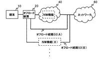
- FIG. 1 is a diagram illustrating a configuration example of a communication system according to the first embodiment.
- the terminal 10 is connected to the offload device 20 and accesses the network 60 via the network 40 or the offload path 50.
- the offload device 20 can transfer to the network 40 and the offload path 50 according to the attribute of the packet received from the terminal 10.
- the network 40 corresponds to the first network, and includes, for example, a network node having a network function (NW: Network) such as S-GW or P-GW.
- NW Network
- Each network node included in the network 40 implements a communication service provided by the communication system by executing processing related to a packet input to the network 40 according to the network function of the network node.
- the offload route 50 is a route that bypasses the network 40 and connects to the network 60.
- the offload route 50 may be one route that bypasses the network 40, or may be a plurality of routes. Further, the offload path 50 may pass the offloaded packet through the network 60 as it is, or a part of the network function of the network 40 may be applied to the packet.
- Network nodes such as gateways, routers, and switches may be separately arranged at the boundaries between the network 40 and the offload path 50 and the network 60.
- both the offload route 50 (A) and the offload route 50 (B) are routes that bypass the network 40 and connect to the network 60.
- the offload path 50 (A) passes the offloaded packet through the network 60 as it is, and the offload path 50 (B) applies the network function (X) to the packet.
- the network function (X) is a part of network functions applicable in the network 40.
- offload paths 50 (C) and 50 (D) may be provided, and different network functions may be applied to packets passing through the respective offload paths.
- the offload apparatus 20 transfers the packet to an appropriate path among the network 40 and the plurality of offload paths 50 (A, B,...) According to the attribute of the packet received from the terminal 10. .
- the communication system illustrated in FIG. 1 includes the following network functions, for example.
- RADIUS Remote Authentication Dial In User Service
- Authentication function A function for authenticating a user who accesses the network
- Authorization function A function for giving access permission to an authenticated user
- Authorization function A function for monitoring access for accounting management (accounting function).
- P-GW ⁇ Packet processing function (User-Plane function) -Function to manage the billing status according to communication (PCEF: Policy and Charging Enforcement Function) -Function to control policies such as QoS (Quality of Service) (PCRF: Policy and Charging Rule Function) ⁇ LI function
- PCEF Policy and Charging Enforcement Function
- LI function S-GW: ⁇ Packet processing function (User-Plane function) ⁇ Function to process control signaling (C-Plane function)
- MME Mobility Management Entity
- ⁇ Manages subscriber information of communication system in cooperation with HSS (Home Subscriber Server) Function base station to: ⁇ Function to perform digital baseband signal processing ⁇ Function to perform analog Radio Frequency (RF) signal processing
- RF Radio Frequency
- FIG. 2 is a diagram illustrating a configuration example of the offload apparatus 20 according to the first embodiment.
- the offload apparatus 20 includes a packet processing unit 210 and a control unit 220.
- the control unit 220 controls the transfer path of the received packet. For example, the control unit 220 selects, as the transfer destination of the received packet, a transfer path according to whether or not it is a target to be offloaded and whether or not it is a target to which a network function is applied.
- the packet processing unit 210 transfers the received packet based on the control of the control unit 220. For example, the packet processing unit 210 transfers the received packet to the route selected by the control unit 220 out of the network 40 and the offload route 50.
- control unit 220 selects the network 40 as a transfer destination of a packet that is not an offload target.
- control unit 220 selects, for example, the offload path 50 (A) as a transfer destination of a packet that is to be offloaded and to which any network function is not applied.
- control unit 220 selects the offload path 50 (B) as a transfer destination of a packet that is an offload target and is an application target of the network function (X).
- the information stored in the packet header can be used. Not limited to.
- the packet attribute the time when the packet is received, the place (position on the network), and the like can be used.
- the necessity of the network function may be determined by combining a plurality of these attributes.
- the control unit 220 may select the transfer path in consideration of, for example, whether the offload function is necessary and whether a plurality of network functions are necessary.
- the packet processing unit 210 transfers the packet to any one of the network 40 and the plurality of offload paths 50 (A, B,%) Depending on whether or not the offload is necessary and the function to be applied.
- FIG. 3 is a diagram illustrating an operation example of the first embodiment.
- the offload apparatus 20 receives a packet from the terminal 10 (S10).
- the offload apparatus 20 selects a route according to the attribute of the received packet as the transfer route of the received packet (S11).
- the attributes of the received packet may relate to whether or not offloading is necessary and whether or not a predetermined function is necessary.
- the offload device 20 transfers the packet to the network 40 and the offload path 50 based on the selection result (S12).
- the control unit 220 may select a predetermined offload route as a transfer destination of the received packet from a plurality of offload routes according to the network function to be applied.
- the transfer path may be selected with reference to a table owned by the offload apparatus 20 or a database outside the apparatus, or according to control information from outside the apparatus. .
- the offload device 20 may be arranged on the network as an individual device, or may be included in, for example, a base station device.
- control device 70 controls the offload device 20. Since the central control of the offload device 20 by the control device 70 is possible, the offload and the network function can be controlled efficiently.
- the technique of the second embodiment can be applied to the technique of the first embodiment and any of the embodiments described later.
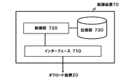
- FIG. 4 is a diagram illustrating a configuration example of the control device 70 according to the second embodiment.
- the control device 70 includes an interface 710, a control unit 720, and a storage unit 730.
- the control device 70 can communicate with the offload device 20 via the interface 710 (corresponding to second and third means).
- the control unit 720 can instruct the control unit 220 of the offload apparatus 20 to select the transfer path of the received packet as in the first embodiment. For example, the control unit 720 selects, as the transfer destination of the received packet, the transfer path according to whether it is an object to be offloaded and whether to apply a network function to the control unit 220. To instruct.
- FIG. 5 is a diagram illustrating a configuration example of the control unit 720 according to the second embodiment.
- the control unit 720 includes an offload control unit 721, a function control unit 722, and a path control unit 723.
- the offload control unit 721 controls packet offload. More specifically, the offload control unit 721 determines whether the predetermined packet is a packet to be offloaded.
- the function control unit 722 controls a network function applied to the packet. For example, the function control unit 722 determines whether a predetermined packet is a packet to which a predetermined network function is applied.
- the function control unit 722 may determine whether or not to apply a plurality of network functions to a packet.
- the offload control unit 721 and the function control unit 722 can refer to, for example, a table included in the storage unit 730.
- FIG. 6 is a diagram illustrating an example of a table included in the storage unit 730 according to the second embodiment.
- the table in the storage unit 730 indicates whether or not offload corresponding to the identification condition is applicable and whether or not the network function is applicable.
- the identification condition is, for example, information on the attribute of the packet received by the offload device.
- the identification condition includes, for example, information on a communication terminal that transmits and receives packets, information on a user who uses the communication terminal, information on a service provided by the network, information for identifying the network, and the like. Further, the identification condition may include information on priority such as QCI (QoS Class Indicator).
- QCI QoS Class Indicator
- a packet that satisfies the condition (a) is not an offload target but an application target of the NW functions (X) and (Y).
- a packet that satisfies the condition (b) is an offload target and is an application target of the NW function (X), but is not an object of the NW function (Y).
- the offload item is stored as applied / not applied, but whether offload is being executed may be stored.
- the path control unit 723 determines the transfer path of the offload device 20 based on the determination results of the offload control unit 721 and the function control unit 722.
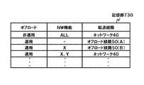
- FIG. 7 is a diagram illustrating an example of a table included in the storage unit 730 according to the second embodiment.
- the table in FIG. 7 shows the transfer path corresponding to the necessity of offloading and the network function to be applied.
- the path control unit 723 determines a transfer path corresponding to the determination results of the offload control unit 721 and the function control unit 723 with reference to the table of FIG.
- the path control unit 723 instructs the control unit 220 to select the determined transfer path.
- the transfer path when offload is not applied, the transfer path is the network 40 regardless of the applied network function.
- the transfer path is the offload path 50 (A).
- the transfer path is the network 40. Further, since a packet that satisfies the identification condition (b) is applied to offload and the network function (X) is an application target, the transfer path is the offload path 50 (B).
- FIG. 8 is a diagram illustrating an operation example of the second embodiment.
- the offload control unit 721 determines whether or not offload is necessary (S20).
- the offload control unit 721 refers to a table as illustrated in FIG. 6 and determines whether or not a packet corresponding to a predetermined identification condition is an offload target.
- the function control unit 722 determines whether the network function needs to be applied (S21). For example, the function control unit 722 refers to a table as shown in FIG. 6 and determines whether to apply to a packet corresponding to a predetermined identification condition.
- the path control unit 723 determines a transfer path based on the determination results of the offload control unit 721 and the function control unit 722 (S22).
- the route control unit 723 determines a transfer route corresponding to the determination results of the offload control unit 721 and the function control unit 722 with reference to a table as illustrated in FIG.
- the path control unit 723 instructs the control unit 220 of the offload apparatus 20 to select the determined transfer path (S23).
- control device 70 may be provided in the offload device 20, and the offload device 20 may realize the above-described control.
- the offload control unit 721 and the function control unit 722 are described as being provided independently, but a configuration in which both are integrated can also be employed. In this case, whether the packet corresponding to the predetermined identification condition is an offload target and the determination of the function to be applied are performed at the same time.
- FIG. 9 is a diagram illustrating a configuration example of the server 80 used in the third embodiment.
- the server 80 includes an interface 810 and an NW function unit 820.
- the server 80 is disposed on the offload path 50 (B) in FIG. 1 and provides the NW function (X). Specifically, the server 80 inputs the received packet to the NW function unit 820 via the interface 810, and sends the packet output from the NW function unit 820 to the offload path 50 (B) side.
- the NW function unit 820 is, for example, a virtual machine, and each NW function is realized by the virtual machine.
- the NW function unit 820 can add or change the NW function provided through the offload route by starting up a virtual machine and causing the virtual machine to provide a desired NW function.
- FIG. 10 is a diagram illustrating an operation example of the third embodiment.
- the offload apparatus 20 receives a packet from the terminal 10 as in the first embodiment (S10).
- the offload device 20 selects a path according to the attribute of the received packet as the transfer path of the received packet, and transfers the packet to the path (S30).
- S10 the attribute of the received packet
- S30 the transfer path of the received packet
- description will be made assuming that it is determined that the offload is applied and the NW function (X) is applied, and the packet is transferred to the offload path 50 (B) in FIG.
- the NW function unit 820 When the server 80 receives the packet, the NW function unit 820 performs processing corresponding to the NW function (X) (S31). At this time, the NW function unit 820 may change the processing content according to the attribute of the packet. When the processing is completed, the server 80 sends the packet to the network 60 side along the offload path 50 (B) of FIG.
- various NW functions can be provided with a simple configuration.
- the reason is that a server 80 that can provide a necessary NW function using a virtual machine is arranged. Further, according to the present embodiment, it is possible to provide a fine-tuned NW function with a simple configuration. The reason is that the NW function unit 820 can change the processing contents according to the attribute of the packet.
- FIG. 11 is a diagram illustrating a configuration example of the server 80A used in the third embodiment.
- the server 80 ⁇ / b> A includes an interface 810, an NW function unit 820, and an information extraction unit 830.
- the server 80A is arranged on the offload path 50 (B) in FIG. 1 and provides the NW function (X). Specifically, the server 80A inputs the received packet to the information extraction unit 830 via the interface 810.
- the information extraction unit 830 extracts necessary information from the input packet and sends it to the NW function unit 820.
- the packet input to the information extraction unit 830 is sent to the offload path 50 (B) side via the interface 810.
- the information extracted from the packet by the information extraction unit 830 is determined by the network function provided by the NW function unit 820.
- the NW function unit 820 provides functions such as packet counting and billing, only information necessary for these processes may be transmitted to the NW function unit 820.
- the NW function unit 820 provides functions such as LI and traffic analysis, the packet itself may be copied and sent to the NW function unit 820.
- the server 80A in addition to the effects of the third embodiment, it is possible to cause the server 80A to perform processing based on information extracted from the packet and processing of the packet.
- the reason is that a configuration is adopted in which the information extraction unit 830 is arranged in the server 80A to extract necessary information.
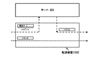
- the present embodiment can be modified to a configuration including a transfer device as shown in FIG.
- the transfer device 100 is arranged by selecting a target packet to be transmitted to the server 80A.
- the transfer device 100 includes a storage unit 1010 and a packet processing unit 1020.
- the storage unit 1010 stores conditions for identifying a target packet to be transmitted to the server 80A and control information that defines a transfer process to the server 80A.
- Such a transfer apparatus 100 can be configured by an open flow switch or the like.
- the packet processing unit 1020 refers to the control information stored in the storage unit 1010, selects a packet to be transmitted to the server 80A from the received packets, and transmits the selected packet to the server 80A.
- FIG. 13 is a diagram illustrating a configuration example of the server 80B used in the fifth embodiment.
- the server 80B is a VM 850-1 to 850-N (N is an upper limit value of the number of VMs that can be started. VM 850-1 to be able to provide a predetermined NW function. ").
- the server 80B is arranged on the offload path 50 (B) in FIG. 1, and provides the NW function using the VM.
- FIG. 14 is a diagram illustrating a configuration example of the control unit 840 of the server 80B according to the fifth embodiment.
- the control unit 840 activates the VM 850 according to the provided NW function, and sends a packet to the VM 850 according to the VM control unit 841 that manages the VM 850 and the attribute information of the packet.
- a path control unit 842 that controls a path including these.
- Such a control unit 840 can be realized by a combination of a control program called a hypervisor and vSwitch operating on the hypervisor.
- FIG. 15 is a diagram illustrating an operation example of the server 80B according to the fifth embodiment.
- the control unit 840 of the server 80B activates a VM necessary for providing a predetermined function, and controls each VM 850 to a state where each function can be provided (S40).
- the VM required for providing the function may be designated by the control device 70 (corresponding to the fourth means).
- control unit 840 determines a VM 850 to which the received packet is to be sent according to the packet attribute information and the like, and performs transfer along the VM. A path to be realized is determined, and a packet is transferred along the path (S42).
- the VM 850 that has received the packet transfer executes a process corresponding to the NW function (S43).
- the server 80B can provide a service chain in which necessary services are chained. Further, according to the present embodiment, it is possible to use different service chains for each packet by the operation of the path control unit 842.
- FIG. 16 is a diagram illustrating another operation example of the server 80B according to the fifth embodiment.
- the control unit 840 of the server 80B activates a VM necessary for providing a predetermined function, and controls each VM 850 to a state in which each function can be provided (S50).
- the control unit 840 identifies the packet (1) from the attribute information of the packet, and the VMs 850-1 and 850-2 are identified. To send the packet. Further, the control unit 840 determines a path for transferring the packet to the VMs 850-1 and 850-2, and transfers the packet along the path (S52).
- the control unit 840 identifies the packet (2) from the packet attribute information, and applies only to the VM 850-1. Decide to send a packet. Further, the control unit 840 determines a path for transferring the packet to the VM 850-1, and transfers the packet along the path (S54).
- the VM 850 that has received the packet transfer executes a process corresponding to the NW function (S55).
- FIG. 17 is a diagram for explaining a path switching (use of service chain) operation according to the packet.
- the packet (1) is an application target of the NW function (X) and the NW function (Y)
- the VM 850-1 that provides the NW function (X) and the VM 850 that provides the NW function (Y) -2 are transferred along a route that passes through both of them.
- the packet (2) is an application target of only the NW function (X)
- the packet (2) is transferred along a route passing through the VM 850-1 that provides the NW function (X).
- a plurality of NW functions to be applied can be combined and freely changed according to packet attributes.
- the NW function applied to the packet can be dynamically switched. For example, in the case of a billing function, by turning off the counting function when the packet count exceeds a certain level, the metering system charges up to a certain number of packets on a pay-as-you-go basis, and when the fixed amount is reached, the pay-as-you-go system and the flat rate system are used together Can be realized.
- control unit 840 determines the VM 850 to which the received packet is to be sent according to the packet attribute information or the like, but the offload device 20 determines a part or all of the VM 850. May be.
- the offload device 20 may give an instruction necessary for selecting a VM in the control unit 840 to the server 80B.
- a transfer device may be arranged in front of the server 80B. In this way, it is possible to select packets to be input to the server 80B.
- FIG. 18 is a diagram illustrating a configuration example of the packet classification device 90 arranged in the front stage of the server 80B used in the sixth embodiment. 18, the packet classification device 90 includes a storage unit 910 and a packet processing unit 920.
- the storage unit 910 holds an identifier assigning rule that defines an identifier to be added according to packet attribute information. Further, this identifier provision rule may be set by the control device 70.
- the packet processing unit 920 refers to the identifier assignment rule in the storage unit 910 and assigns an identifier to the received packet.
- the description is given assuming that an external header storing an identifier is added to the packet, but the method of adding the identifier is not limited to this method.
- the identifier may be stored in a predetermined area of the header of the original packet.
- the function corresponding to the packet classification device 90 may be assigned to the offload device 20.
- control unit 840 of the server 80B determines a VM to which the received packet is to be sent and a path for realizing the transfer to the VM based on the identifier.
- FIG. 19 is a diagram for explaining the path switching (use of different service chains) operation using the identifier assigned by the packet classification device 90.
- a packet to which a certain identifier is assigned is an application target of the NW function (X) and the NW function (Y)
- the VM 850-1 that provides the NW function (X) and the NW function (Y) It is transferred along a route that passes through both of the provided VM 850-2s.
- a packet with a different identifier is configured not to pass through either one or both of the VM 850-1 providing the NW function (X) and the VM 850-2 providing the NW function (Y). You can also.
- a packet with another different identifier can be controlled to pass through a VM 850 that provides another NW function (Z).
- the transfer device 100 may be arranged in the front stage of the server 80 ⁇ / b> B. In this way, it is possible to select packets to be input to the server 80B.
- the transfer device 100 illustrated in FIG. 20 may have a function corresponding to the packet classification device 90.
- the transfer apparatus 100 having such a packet classification function can be realized by an open flow switch in which a flow entry for header rewriting is set.
- FIG. 21 is a diagram illustrating a configuration example of the operation management apparatus 110 used in the seventh embodiment.
- the operation management apparatus 110 includes an offload management unit 1110, a function management unit 1120, and an interface 1130.
- the offload management unit 1110 receives the operation contents of the table shown in FIG. 6 from the network operator, and updates the table held in the storage unit 730 of the control device 70. For example, the offload management unit 1110 receives an operation of changing the entry of the condition (a) in FIG. 6 from non-offload application to application, and updates the contents of the storage unit 730. As a result, the packet that satisfies the condition (a) is changed to an offload application target.
- the function management unit 1120 receives the operation contents of the tables shown in FIGS. 6 and 7 from the network operator, and updates the table held in the storage unit 730 of the control unit 70. For example, the function management unit 1120 receives an operation for changing some of the NW functions in the entry of the condition (b) in the figure from non-application to application, and updates the contents of the storage unit 730. As a result, the NW function applied to packets that meet the condition (b) is changed thereafter.
- the offload management unit 1110 and the function management unit 1120 have been described by taking an example in which the table held in the storage unit 730 of the control device 70 is directly updated.
- a control policy that defines a table update policy may be received and set in the control device 70. For example, when a certain time comes, a control policy for changing the offload setting of the condition (a) in the table of FIG. 6 from application (non-application) to non-application (application), or a specific entry in the table of FIG. By setting the control policy to be added, the table change can be automated.
- a control policy may be set in which the transfer path field in the table of FIG. 7 is dynamically changed according to the network load or the like.
- control device 70 is controlled from the operation management device 110 .
- the offload device in FIG. 1 and the packet classification device 90 in FIG. You may enable it to control from the apparatus 110.
- the server control policy described in the third to sixth embodiments may be set from the operation management apparatus 110.
- FIG. 22 is a network diagram showing the configuration of the eighth embodiment.
- a mobile terminal UE (User Entity) 1000 includes a base station eNB2000 functioning as the offload device 20 described above, an S / P-GW3000 (S-GW + P-GW) serving as a mobile core device, and an OFS.
- a configuration for connecting to a PDN (Packet Data Network) 10000 via an (OpenFlow switch) 4000 and a router 6000 is shown.
- the OFS 4000 shows a configuration in which a RADIUS server 5000, an OFC (Open Flow Controller) 7000, and an LI-IF 8000, which is an interface for accepting an execution request for LI (Lawful Interception), are connected.
- the base station eNB2000 connects to the UE 10 in the service area via a radio link. Further, an offload route 9000 that does not pass through the S / P-GW 3000 is set between the eNB 2000 and the OFS 4000.
- the OFS 4000 searches the stored flow entries for a flow entry having a matching condition that matches the received packet, and processes the processing contents (transfer on the designated route, header rewriting, packet discard, etc.) determined for the flow entry. carry out.
- the OFS 4000 transmits information on the received packet to the OFC 7000 and requests setting of the flow entry.
- the RADIUS server 5000 functions as an AAA (Authentication, Authorization, Accounting) server that controls authentication, authorization, and accounting.
- AAA Authentication, Authorization, Accounting
- the router 6000 is a device that performs relay control in layer 3.
- MME Mobility Management Entity
- HSS Home Subscriber Server
- PCRF Policy and Charging Rule Function
- the OFC 7000 corresponds to the control device 70 in the control device of the second embodiment described above, and controls the offload function of the OFS 4000.
- the LI-IF 8000 is connected to the OFC 7000, and is also connected to a law enforcement agency (LEA: Law enforcement agency) intercepting device (LEMF: Law enforcement facility) that has a lawful intercept execution authority (not shown).
- LEA Law enforcement agency
- LEMF Law enforcement facility
- FIG. 23 is a block diagram showing an example of a detailed configuration of the OFC 7000.
- the OFC 7000 of this embodiment includes an interface 7010, a control unit 7020, an LI request processing unit 7030, and a management database 7040.
- the interface 7010, the control unit 7020, and the management database 7040 in FIG. 23 correspond to the interface 710, the control unit 720, and the storage unit 730 of the control device 70 illustrated in FIG. Therefore, the OFC 7000 in FIG. 23 has a configuration in which an LI request processing unit 7030 is added to the control device 70 in FIG.
- the management database 7040 holds a UE information management table shown in FIG.
- the UE information management table is at least for each terminal registered in the mobile network, for example, IMSI (International Mobile Subscriber Identity), which is unique information for specifying a user, and an IP (Internet Protocol) address assigned to the terminal.
- IMSI International Mobile Subscriber Identity
- IP Internet Protocol
- a radio bearer identifier E-RABID a flow entry ID set in the OFC 4000, a usage state of the offload function, and a usage state of the LI function.
- the IMSI to flow entry ID in FIG. 24 correspond to the identification conditions in FIG. 6, the use state of the offload function corresponds to the offload setting field in FIG.
- the fields included in the UE information management table are not limited to the items described above.
- MSISDN may be used instead of IMSI as an ID for identifying a user, or may be added to the table as another field.
- E-RABID may be information that can identify a radio bearer
- information such as TMSI and TEID may be used instead of E-RABID, and the accuracy of information to be managed is improved.
- a field corresponding to TMSI or TEID may be added.
- a VLAN ID field may be added to the UE information management table.
- the flow entry ID need only be able to identify the flow entry set in the OFC 4000. If there is an alternative method, it is not always necessary to record the flow entry ID. For example, it is possible to specify the flow entry set in the OFS by searching for the IP address of the terminal as a key. However, in this case, since a large number of flow entries are searched each time, it takes time to change the flow entry for offload control. Further, in the example of FIG. 24, only the LI state field is provided, but similarly to FIG. 6, a field for setting application / non-application of other mobile core functions such as charging may be added. Or it can also generalize as a use state of a mobile core function, and it can also manage the use state of a plurality of mobile core functions in one field.
- the management database 7040 holds information for creating a flow entry set in the OFS 4000 by the control unit 7020 such as terminal information and network topology information.
- the management database 7040 may hold the created flow entry so that an appropriate flow entry can be paid out in response to a request from the OFS 4000.
- the control unit 7020 includes an offload control unit 7021, an LI control unit 7022, and an entry control unit 7023.
- the offload control unit 7021 When the offload control unit 7021 receives a flow entry creation request from the OFS 4000, the offload control unit 7021 refers to the management database 7040, determines whether the offload application of the corresponding packet is necessary, and passes it to the entry control unit 7023.
- the LI control unit 7022 When the LI control unit 7022 receives a flow entry creation request from the OFS 4000, the LI control unit 7022 refers to the management database 7040, determines whether the LI application of the corresponding packet is necessary, and passes it to the entry control unit 7023.
- the entry control unit 7023 determines whether or not the offload is necessary and whether or not to apply the LI function, and sends a packet along a path that realizes these. A flow entry to be transferred is created and set in the OFS 4000. Further, the entry control unit 7023 notifies the eNB 2000 of the necessity of offloading and the necessity of application of the LI function.
- the LI request processing unit 7030 receives a communication LI request or an end request designating an IMSI or IP address from the LI-IF 8000 and notifies the control unit 7020 of the request.
- the eighth embodiment operates as follows in comparison with the second embodiment.
- (1-1) When receiving an LI request designating an IMSI, IP address, or the like from the LI request processing unit 7030, the control unit 7020 refers to the management database 7040 to find a corresponding entry, and sets the LI status field. Update the contents.
- the control unit 7020 confirms the offload state of the corresponding entry.
- the control unit 7020 turns OFF (offload non-loading). Switch to (Apply) (Reselect route).
- the control unit 7020 checks the offload state of the corresponding entry, and when the LI state is OFF (offload non-applicable), it is ON. Switch to (Apply offload) (Reselect route). Then, the transfer through the S / P-GW 3000 is stopped with respect to the OFS 4000 and the eNB 2000, and the packet is switched to transfer the packet through the offload route 9000.
- the control unit 7020 of the OFC 7000 refers to the management database 7040. To find the corresponding entry and refer to its LI status field.
- the control unit 7020 sends a path through the S / P-GW 3000 to the OFS 4000 and the eNB 2000 regardless of the value of the offload status field.
- FIG. 25 is a network diagram showing a configuration of the ninth embodiment.
- the OFS 4000 is different from the eighth embodiment in that an interception packet receiving server 11000 called Delivery Function (DF) and a server 12000 are added.
- DF Delivery Function
- the server 12000 corresponds to the servers 80 to 80B of the third to sixth embodiments, and provides the NW function (X) for the packet received from the OFS 4000.
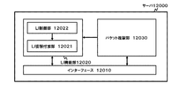
- FIG. 26 is a diagram illustrating a configuration example of the server 12000.
- the server 12000 includes an interface 12010, an LI function unit 12020, and a packet duplication unit 12030.
- the interface 12010 is the same as the interface 810 of the server 80A of the fourth embodiment shown in FIG.
- the packet duplicating unit 12030 When receiving the packet from the OFS 4000 side, the packet duplicating unit 12030 duplicates the packet and sends it to the LI function unit 12020. Further, the packet duplication unit 12030 sends the duplication source packet back to the OFS 4000 side.
- the LI function unit 12020 includes an LI control unit 12022 and an LI information addition unit 12021.
- the LI control unit 12022 sends an LI start or end instruction and LI information to be added as LI information to the LI information adding unit 12021 from the LI control packet.
- the LI information adding unit 12021 adds the LI information instructed by the LI control unit 12022 to the interception target packet and outputs it.
- the DF 11000 is set as the transmission destination of the packet to which the LI information is added by the LI information adding unit 12021, and is transferred via the OFS 4000. In the example of FIG. 25, the DF 11000 is connected to the OFS 4000, but the DF 11000 may be connected to the server 12000, and the packet with the LI information added may be directly transmitted from the server 12000 to the DF 11000.
- FIG. 27 is a diagram illustrating a configuration example of the server 12000A.
- the server 12000A includes an interface 12010 and a charging function unit 12040.
- the charging function unit 12040 includes a charging function processing unit 12041 and a charging function control unit 12042.
- the charging function control unit 12042 sends a charging process start instruction and end instruction to the charging function processing unit 12041 in accordance with predetermined charging start conditions and end conditions.
- the charging function processing unit 12041 performs charging processing based on a packet received via the interface 12010 in accordance with an instruction from the charging function control unit 12042.
- FIG. 28 is a diagram illustrating a configuration example of the OFC 7000A in the case where a server 12000A that provides a charging function is arranged.
- a difference from the OFC 7000 shown in FIG. 23 is that a charging function control unit 7052 is provided in the control unit 7050 instead of the LI control unit 7022.
- the offload control unit 7051 When the offload control unit 7051 receives a flow entry creation request from the OFS 4000, similarly to the offload control unit 7021 of the control unit 7020 of the OFC 7000 of the eighth embodiment, the offload control unit 7051 refers to the management database 7040 and The necessity of offload application is determined and passed to the entry control unit 7053.
- the charging function control unit 7052 Upon receipt of the flow entry creation request from the OFS 4000, the charging function control unit 7052 refers to the management database 7040, determines whether or not charging of the corresponding packet is necessary, and passes it to the entry control unit 7053.
- the entry control unit 7053 determines whether or not the offload is necessary and whether or not the charging function is to be applied. A flow entry to be transferred is created and set in the OFS 4000. Further, the entry control unit 7053 notifies the eNB 2000 of whether or not an offload is necessary and whether or not a charging function is necessary.
- FIG. 29 is a diagram illustrating a configuration example of the server 12000B.
- the server 12000B includes an interface 12010 and a filter function unit 12050.
- the filter function unit 12050 includes a filter processing unit 12051 and a filter function control unit 12052.
- the filter function control unit 12052 instructs the filter function control unit 12052 to turn on / off the filter function and filter conditions in accordance with predetermined filter settings.
- the filter processing unit 12051 performs a filtering process based on a packet received via the interface 12010 in accordance with an instruction from the filter function control unit 12052.
- the filtering process includes a filtering process for harmful contents for children.
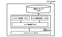
- FIG. 30 is a diagram illustrating a configuration example of the OFC 7000B when the server 12000B providing the filtering function is arranged.
- a difference from the OFC 7000 shown in FIG. 23 is that a filter function control unit 7062 is provided in the control unit 7060 instead of the LI control unit 7022.
- the offload control unit 7061 When the offload control unit 7061 receives a flow entry creation request from the OFS 4000 as in the offload control unit 7021 of the control unit 7020 of the OFC 7000 of the eighth embodiment, the offload control unit 7061 refers to the management database 7040 and The necessity of offload application is determined and passed to the entry control unit 7063.
- the filter function control unit 7062 When the filter function control unit 7062 receives a flow entry creation request from the OFS 4000, the filter function control unit 7062 refers to the management database 7040, determines whether or not filter control of the corresponding packet is necessary, and passes it to the entry control unit 7063.
- the entry control unit 7063 determines whether or not the offload is necessary and whether or not the filtering function is applied, and the packet is transmitted along a path that realizes these. A flow entry to be transferred is created and set in the OFS 4000. Further, the entry control unit 7063 notifies the eNB 2000 of the necessity of offloading and the necessity of applying the filtering function.
- the LI function unit 12020 corresponds to an example of the NW function unit 820 of the server 80A of the fourth embodiment shown in FIG. 11, and the packet duplication unit 12030 is the server 80A of the fourth embodiment shown in FIG. This corresponds to an example of the information extraction unit 830.
- the accounting function unit 12030 and the filter function unit 12050 correspond to an example of the NW function unit 820 of the server 80 according to the third embodiment illustrated in FIG.
- the NW function unit 820 of the servers 80 to 80A is not limited to the LI function, the billing process, and the filtering process, and can be applied to provide various NW functions.
- the functions corresponding to the servers 12000, 12000A, and 12000B can be realized by the VM.
- a service chain can be configured by selecting an arbitrary NW function and applied to a specific flow.
- the offload network side can be provided with an LI function, a charging function, and a filtering function. Even when an LI request is received, there is an advantage that it is not necessary to immediately stop offloading. Further, according to the present embodiment, even if the traffic is not applied to off-road, it is possible to switch to the off-road route as long as the conditions are satisfied. This is because the server 12000 (12000A, 12000B) is connected to the OFS 4000 on the offload path side, and a specific NW function can be selected and applied.
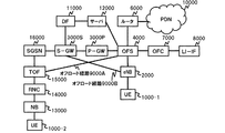
- FIG. 31 is a diagram illustrating a configuration example of a communication system according to the tenth embodiment.
- the difference in configuration from the ninth embodiment shown in FIG. 25 is that the first UE 1000-1 is connected to the OFS 4000 and S-GW 3000S via the base station eNB2000, and the second UE 1000 -2 is connected to the OFS 4000 and the SGSN (Serving GPRS Support Node; also referred to as “subscriber packet switch”) 16000 via the base station NB 13000, the radio network controller (RNC) 14000, and the TOF (traffic offload device) 15000.
- RNC radio network controller
- the OFC 7000 that controls the offload function operates in the same manner as in the ninth embodiment shown in FIG. That is, when the OFC 7000 receives a connection request, which is an offload request, from the TOF 15000 via the OFS 4000, the server 12000 determines whether the terminal to be offloaded (UE 1000-2 in FIG. 31) is using the LI function. Route control according to whether or not offloading is possible. For example, when the UE 1000-2 is not using the LI function, the OFC 7000 sends a flow entry for switching to the offload path to the OFS 4000 and instructs the TOF 15000 to transfer via the offload path 9000A.
- the TOF 15000 Upon receiving the instruction, the TOF 15000 applies offload to the bearer to be offloaded and starts communication via the offload path 9000A.
- the OFC 7000 instructs the TOF 15000 not to apply offload.
- the TOF 15000 that has received the instruction performs communication through a route that passes through the mobile core (SGSN 16000).
- the OFC 7000 of this embodiment operates in the same manner as in the case of the eighth embodiment also in the control of the offload function accompanying the use of the LI function. That is, when the OFC 7000 receives an LI request from the LI-IF 8000, the OFC 7000 performs control according to the offload state of the LI target terminal. For example, if the communication of the UE 1000-2 that is the target of the LI request is not offloaded, the OFC 7000 that has received the LI request does not perform any control, and the TOF 15000 continues the communication via the mobile core.
- the communication of the UE 1000-2 that is the target of the LI request is offloaded, a flow entry for switching to the path on the mobile core side is sent to the OFS 4000, and the offload application is terminated to the TOF 15000. Instruct.
- the TOF 15000 that has received the instruction to end offload (offload non-application) ends the offload operation for the bearer that is the target of offloading, and switches to communication via the mobile core (SGSN 16000).
- the point that records and manages the offload state and the LI state in the UE information management table of the management database 7040 in the OFC 7000 is the same as in the case of the eighth embodiment.
- a server 12000 is connected to the OFS 4000 as in the ninth embodiment.
- the OFC 7000 instructs the OFS 4000 to transfer to the server 12000 even when the communication of the UE 1000-2 that is the target of the LI request is offloaded. It is also possible to continue the offload application to the TOF 15000 by sending an entry.
- FIG. 32 is a diagram illustrating a configuration example of a communication system according to an eleventh embodiment in which the present invention is applied to a femtocell radio communication system.
- the router 6000, PDN10000, OFS4000, OFC7000, LI-IF8000, server 12000, DF11000, and S / P-GW 3000 on the right side of FIG. 32 are the same as those in the ninth embodiment shown in FIG.
- the OFS4000 is connected to a femto gateway (Femto-GW) 20000 having a traffic offload (TOF) function via an offload route 9000C.
- the femto gateway 20000 is connected to a femtocell base station (femtocell) via the Internet 21000 Cell access point (FAP) 22000.
- FAP Cell access point
- the OFC 7000 operates in the same manner as the above eighth to tenth embodiments. That is, when the OFC 7000 receives a connection request that becomes an offload request, the OFC 7000 refers to the UE information management table in the management database 7040 to determine whether or not the terminal 23000 to be offloaded is using the LI function. When the offload target terminal 23000 does not use the LI function, the OFC 7000 determines that offload is possible. Then, the OFC 7000 sets a flow entry to instruct the OFS 4000 to transfer via the offload path 9000C and instructs the femto gateway 20000 to apply offload.
- the offload of the femto gateway 20000 is started, and the packet to be offloaded is transferred to the OFS 4000 via the offload route 9000C that bypasses the core network, and is transferred from the router 6000 to the PDN 10000.
- a packet transferred from the PDN 10000 to the OFS 4000 via the router 6000 is transferred to the femto gateway 20000 via the offload route 9000C that bypasses the core network, and is transferred to the FAP 22000 through the Internet 21000.
- the OFC 7000 receives an LI request from the LI-IF 8000, similarly, control is performed according to the offload state of the terminal 23000 targeted for the LI. If the communication of the LI target terminal 23000 is not offloaded, the OFC 7000 does not perform any control and causes the femto gateway 20000 to continue communication via the mobile core. On the other hand, when the communication of the terminal 23000 targeted for LI is offloaded, the OFC 7000 transmits a flow entry to the OFS 4000 and instructs the femto gateway 20000 to end offloading in order to switch to the route on the mobile core side. To switch to communication via mobile cores (SGSN 16000 and S / P-GW 3000). As in the eighth embodiment, the offload state and the LI state are recorded and managed in the UE information management table of the management database 7040 in the OFC 7000.
- the server 12000 is connected to the OFS 4000 as in the ninth embodiment.
- the OFC 7000 instructs the OFS 4000 to transfer to the server 12000 even if the communication of the terminal 23000 that is the target of the LI request is offloaded. It is also possible to continue offload application to the femto gateway 20000.
- the present invention can be applied to both the offload of communication via the FAP22000 and the application of the NW function.
- FIG. 33 is a diagram illustrating a configuration example of a communication system according to a twelfth embodiment in which the present invention is applied to a wireless LAN (Local Area Network) communication system.
- the server 12000B, OFC 7000B, OFS 4000, router 6000, and PDN 10000 in FIG. 33 are the same as those in the ninth embodiment shown in FIG.
- the OFS 4000 is connected to a wireless LAN access point (WLAN-AP) 26000 via an offload path 9000D.
- WLAN-AP wireless LAN access point
- the WLAN-AP 26000 is connected to a Trusted WLAN Access Gateway (TWAG) 27000 and a Trusted WLAN AAA Proxy (TWAP) 24000.
- TWAG Trusted WLAN Access Gateway
- TWAP Trusted WLAN AAA Proxy
- the TWAP 24000 is connected to a subscriber database (HLR (Home Location Register) / HSS) 25000.
- HLR Home Location Register
- the OFC 7000B operates in the same manner as the ninth embodiment. That is, when the OFC 7000B receives a connection request that is an offload request, the OFC 7000B refers to the UE information management table in the management database 7040 to determine whether or not the UE 1000 is using the filtering function. If the offload target UE 1000 does not use the filtering function, the OFC 7000B determines that offload is possible. Then, the OFC 7000B sets a flow entry for instructing transfer to the OFS 4000 via the off-load path 9000D and instructs the WLAN-AP 26000 to apply off-load.
- the offload of the WLAN-AP 26000 is started, and the offload target packet is transferred to the OFS 4000 via the offload path 9000D that bypasses the TWAG 23000 and the TWAP 24000, and is transferred from the router 6000 to the PDN 10000. Further, the packet transferred from the PDN 10000 to the OFS 4000 via the router 6000 is transferred to the WLAN-AP 26000 via the offload path 9000D that bypasses the core network, and is transferred to the UE 1000.
- the above-described control is not performed, and communication is performed via a normal TWAG 23000 and TWAP 24000 route that does not perform offload.
- the server 12000B is connected to the OFS 4000 as in the ninth embodiment.
- the server 12000B has a filtering function, it is not necessary to immediately stop offloading even when a request to use filtering is made, and the OFC 7000 instructs the OFS 4000 to transfer the target packet to the server 12000B. It is also possible to continue the offload application to the WLAN-AP 26000 by sending an entry.
- each unit such as the offload device, control device, server, OFC, etc., shown in each of the above figures executes the above-described processing using the hardware of the computer that constitutes these devices. It can also be realized by a computer program.
- a control apparatus comprising a fourth means for instructing the first means to add a network function according to an attribute of the received packet.
- the fourth means is a control device that instructs the first means to configure a service chain in which a plurality of network functions are connected.
- the network function includes a control device including at least one of a lawful intercept function, a billing function, and a filtering function.
- a control device that uses identification information of a transmission source device as an attribute of the received packet.
- [Sixth embodiment] (Refer to the communication system according to the second viewpoint)
- [Seventh form] (Refer to the network function providing device from the third viewpoint)
- [Eighth form] (Refer to the communication method from the fourth viewpoint above.)
- [Ninth Embodiment] (Refer to the computer program according to the fifth aspect above)
- [Tenth embodiment] A first route connected to the second network via a first network having a plurality of network functions, and a second route bypassing the first network and connected to the second network
- the first means is a communication device that selects a transfer path capable of realizing a network function in accordance with an attribute of the received packet based on an instruction from a predetermined control device.
- the communication device of the tenth or eleventh aspect When the first means receives a use start request or a use end request for a function applied to the received packet, the communication device performs reselection of a transfer path that can realize the function.
- the first means is a communication device that selects the first route when the second route cannot realize a network function according to an attribute of the received packet.
- a server that provides the network function of the first network is arranged in the second route,
- the first means is a communication device that selects a route on which a server capable of providing a network function according to an attribute of a received packet is arranged.
- the network function includes a communication device including at least one of a lawful intercept function, a charging function, and a filtering function.
- a control apparatus comprising: means connected to the communication apparatus according to any one of the tenth to sixteenth aspects; and means for transmitting control information for selecting the route to the first means of the communication apparatus.
- a communication system including the communication device according to any one of the tenth to sixteenth aspects and the control device according to the seventeenth aspect.
- [19th form] A first route connected to the second network via a first network having a plurality of network functions, and a second route bypassing the first network and connected to the second network Selecting a transfer path that realizes a network function according to an attribute of the received packet from the plurality of paths including a plurality of network functions, and transferring the received packet to the transfer path. Including communication methods.
- a first route connected to the second network via a first network having a plurality of network functions, and a second route bypassing the first network and connected to the second network A process of selecting a transfer path that realizes a network function according to an attribute of the received packet from the plurality of paths including the process, and a process of transferring the received packet to the transfer path.
- a program to be executed by a computer installed in a communication device can be developed into the second to fifth embodiments in the same manner as the first embodiment.
- the seventeenth to twentieth forms can be developed into the eleventh to sixteenth forms as in the tenth form.
- 10 terminal 20 offload device 40 (first) network 50 (A) to 50 (X), 9000, 9000A to 9000D offload path 60 (second) network 70 control device 80, 80A, 80B server 90 packet classification Device 100 Transfer device 110 Operation management device 210, 1020 Packet processing unit 220 Control unit 710, 810, 1130, 7010, 12010 Interface 720, 840, 7020, 7050, 7060 Control unit 721 Offload control unit 722 Function control unit 723 Path control Unit 730, 910, 1010 storage unit 820 NW function unit 830 Information extraction unit 841 VM control unit 842 Path control unit 850-1 to 850-N Virtual machine (VM) 920, 1020 packet processing unit 1000 UE 1110 Offload management unit 1120 Function management unit 1000, 1000-1 to 1000-2 UE 2000 Base station eNB with offload function 3000 S / P-GW 3000S S-GW 3000P P-GW 4000 OFS 5000 RADIUS server 6000 Router 7000, 7000A, 7000B OFC 70
Abstract
Description
本発明は、日本国特許出願:特願2015-056369号(2015年3月19日出願)及び特願2015-056368号(2015年3月19日出願)に基づくものであり、同出願の全記載内容は引用をもって本書に組み込み記載されているものとする。
本発明は、制御装置、通信システム、ネットワーク機能提供装置、通信装置、通信方法及びプログラムに関し、特に、そのネットワーク機能の提供に関する。 [Description of related applications]
The present invention is based on Japanese patent applications: Japanese Patent Application No. 2015-056369 (filed on March 19, 2015) and Japanese Patent Application No. 2015-056368 (filed on March 19, 2015). It is assumed that the description is incorporated in this document by reference.
The present invention relates to a control device, a communication system, a network function providing device, a communication device, a communication method, and a program, and more particularly to providing the network function.
なお、前記した制御装置、通信システム、ネットワーク機能提供装置、通信方法及びプログラムの各要素は、それぞれ上記した課題の解決に貢献する。 According to a fifth aspect, the packet is transferred to a path in which a first device that provides at least one network function of the plurality of network functions of the first network having a plurality of network functions is arranged, or A process for determining whether to transfer a packet to the first network according to the attribute of the received packet, and a process for instructing a predetermined packet transfer apparatus to transfer a received packet to the computer according to the determination. A program to be executed is provided. This program can be recorded on a computer-readable (non-transient) storage medium. That is, the present invention can be embodied as a computer program product.
Each element of the control device, the communication system, the network function providing device, the communication method, and the program described above contributes to solving the above-described problems.
本発明の第1の実施形態では、オフロード装置が、パケットの属性に関する識別情報に応じて、オフロードの要否と所定のネットワーク機能の要否とに応じたパケットの転送先を選択することが可能である。従って、第1の実施形態によれば、トラフィックオフロードを実現しつつ、所定のネットワーク機能を適用することができる。 [First Embodiment]
In the first embodiment of the present invention, the offload apparatus selects a packet transfer destination according to whether or not an offload is necessary and whether or not a predetermined network function is necessary according to identification information related to the attribute of the packet. Is possible. Therefore, according to the first embodiment, it is possible to apply a predetermined network function while realizing traffic offload.
RADIUS(Remote Authorization Dial In User Service):
・ネットワークにアクセスするユーザを認証する機能(Authentication機能)。
・認証したユーザに対して、アクセス許可を与える機能(Authorization機能)。
・課金管理のため、アクセスを監視する機能(Accounting機能)。
P-GW:
・パケットを処理する機能(User-Plane機能)
・通信に応じた課金状態を管理する機能(PCEF:Policy and Charging Enforcement Function)
・QoS(Quality of Service)等のポリシーを制御する機能(PCRF:Policy and Charging Rule Function)
・LI機能
S-GW:
・パケットを処理する機能(User-Plane機能)
・制御シグナリングを処理する機能(C-Plane機能)
MME(Mobility Management Entity):
・制御シグナリングを処理する機能(C-Plane機能):例えば、通信用のセッションの設定・解放、ハンドオーバーの制御等
・HSS(Home Subscriber Server)と連携して、通信システムの加入者情報を管理する機能
基地局:
・デジタルベースバンド信号処理を行う機能
・アナログRadio Frequency(RF)信号処理を行う機能 The communication system illustrated in FIG. 1 includes the following network functions, for example.
RADIUS (Remote Authentication Dial In User Service):
A function for authenticating a user who accesses the network (Authentication function).
A function for giving access permission to an authenticated user (Authorization function).
A function for monitoring access for accounting management (accounting function).
P-GW:
・ Packet processing function (User-Plane function)
-Function to manage the billing status according to communication (PCEF: Policy and Charging Enforcement Function)
-Function to control policies such as QoS (Quality of Service) (PCRF: Policy and Charging Rule Function)
・ LI function S-GW:
・ Packet processing function (User-Plane function)
・ Function to process control signaling (C-Plane function)
MME (Mobility Management Entity):
・ Function to process control signaling (C-Plane function): For example, setting / release of communication session, control of handover, etc. ・ Manages subscriber information of communication system in cooperation with HSS (Home Subscriber Server) Function base station to:
・ Function to perform digital baseband signal processing ・ Function to perform analog Radio Frequency (RF) signal processing
本発明の第2の実施形態では、制御装置70が、オフロード装置20を制御する。制御装置70によるオフロード装置20の集中制御が可能なため、オフロードとネットワーク機能の制御を効率的に行うことができる。第2の実施形態の技術は、第1の実施形態及び後述するいずれの実施形態の技術にも適用することができる。 [Second Embodiment]
In the second embodiment of the present invention, the control device 70 controls the
続いて、前記オフロード経路上にNW機能を提供するサーバ(ネットワーク機能提供装置(第1の手段に相当))を配置した第3の実施形態について図面を参照して説明する。以下、第1の実施形態との共通点は省略し、その相違点を中心に説明する。 [Third Embodiment]
Next, a third embodiment in which a server (network function providing device (corresponding to the first means)) that provides an NW function is arranged on the offload route will be described with reference to the drawings. Hereinafter, common points with the first embodiment will be omitted, and the differences will be mainly described.
続いて、第3の実施形態のサーバに変更を加えた第4の実施形態について図面を参照して説明する。以下、第3の実施形態との共通点は省略し、その相違点を中心に説明する。 [Fourth Embodiment]
Next, a fourth embodiment in which a change is made to the server of the third embodiment will be described with reference to the drawings. Hereinafter, common points with the third embodiment will be omitted, and the differences will be mainly described.
続いて、第3の実施形態のサーバに変更を加えた第5の実施形態について図面を参照して説明する。以下、第3の実施形態との共通点は省略し、その相違点を中心に説明する。 [Fifth Embodiment]
Next, a fifth embodiment in which a change is made to the server of the third embodiment will be described with reference to the drawings. Hereinafter, common points with the third embodiment will be omitted, and the differences will be mainly described.
続いて、第5の実施形態のサーバにおけるサービスチェインの切替を、パケットに付加された識別子に基づいて実施するようにした第6の実施形態について図面を参照して説明する。以下、第5の実施形態との共通点は省略し、その相違点を中心に説明する。 [Sixth Embodiment]
Next, a sixth embodiment in which service chain switching in the server of the fifth embodiment is performed based on an identifier added to a packet will be described with reference to the drawings. Hereinafter, common points with the fifth embodiment will be omitted, and differences will be mainly described.
続いて、第2の実施形態の制御装置に対して、必要な指示を与える運用管理装置を配置した第7の実施形態について図面を参照して説明する。以下、第2の実施形態との共通点は省略し、その相違点を中心に説明する。 [Seventh Embodiment]
Next, a seventh embodiment in which an operation management device that gives necessary instructions to the control device of the second embodiment is arranged will be described with reference to the drawings. Hereinafter, common points with the second embodiment will be omitted, and the differences will be mainly described.
続いて、本発明をモバイルネットワークにおけるオフロード制御に適用した第8の実施形態について図面を参照して詳細に説明する。図22は、第8の実施形態の構成を示すネットワーク図である。 [Eighth Embodiment]
Next, an eighth embodiment in which the present invention is applied to offload control in a mobile network will be described in detail with reference to the drawings. FIG. 22 is a network diagram showing the configuration of the eighth embodiment.
(1-1)LI要求処理部7030から、IMSIやIPアドレス等を指定したLI要求を受けた場合、制御部7020は、管理データベース7040を参照して、該当するエントリを探し出し、LI状態フィールドの内容を更新する。ここで、例えば、LI状態がOFFからONに変更された場合、制御部7020は、該当するエントリのオフロード状態を確認し、ON(オフロード適用)になっている場合、OFF(オフロード非適用)に切り替える(経路の再選択)。そして、OFS4000とeNB2000に対してオフロード経路9000での転送を中止し、S/P-GW3000を経由する経路でパケットを転送するよう切り替える。
(1-2)反対に、LI状態がONからOFFに変更された場合、制御部7020は、該当するエントリのオフロード状態を確認し、OFF(オフロード非適用)になっている場合、ON(オフロード適用)に切り替える(経路の再選択)。そして、OFS4000とeNB2000に対してS/P-GW3000を経由する転送を中止し、オフロード経路9000でパケットを転送するよう切り替える。
(2-1)また、OFC7000が、基地局eNB2000やOFSから、IMSIやIPアドレス等を指定したオフロード要否の判定要求を受けた場合、OFC7000の制御部7020は、管理データベース7040を参照して、該当するエントリを探し出し、そのLI状態フィールドを参照する。ここで該当するエントリのLI状態フィールドがON(LI実施中)である場合、制御部7020は、OFS4000とeNB2000に対してオフロード状態フィールドの値に拘わらず、S/P-GW3000を経由する経路での転送を指示する。
(2-2)一方、該当するエントリのLI状態フィールドがOFF(LI不実施)である場合、制御部7020は、オフロード状態フィールドの値をOFF(オフロード非適用)に変更し、OFS4000とeNB2000に対してオフロード経路9000でパケット転送を指示する。 The eighth embodiment operates as follows in comparison with the second embodiment.
(1-1) When receiving an LI request designating an IMSI, IP address, or the like from the LI request processing unit 7030, the control unit 7020 refers to the
(1-2) On the other hand, when the LI state is changed from ON to OFF, the control unit 7020 checks the offload state of the corresponding entry, and when the LI state is OFF (offload non-applicable), it is ON. Switch to (Apply offload) (Reselect route). Then, the transfer through the S / P-
(2-1) When the
(2-2) On the other hand, when the LI status field of the corresponding entry is OFF (LI not implemented), the control unit 7020 changes the value of the offload status field to OFF (offload non-applicable), and the OFS 4000 A packet transfer is instructed to the
続いて、上記第8の実施形態の構成に、NW機能を提供するサーバを追加した第9の実施形態について図面を参照して詳細に説明する。図25は、第9の実施形態の構成を示すネットワーク図である。図25を参照すると、OFS4000に、Delivery Function(DF)と呼ばれる傍受パケットの受信サーバ11000と、サーバ12000が追加されている点で第8の実施形態と相違している。 [Ninth Embodiment]
Next, a ninth embodiment in which a server that provides an NW function is added to the configuration of the eighth embodiment will be described in detail with reference to the drawings. FIG. 25 is a network diagram showing a configuration of the ninth embodiment. Referring to FIG. 25, the
続いて、上記第9の実施形態の変形実施形態である第10~第12の実施形態を説明する。図31は、第10の実施形態に係る通信システムの構成例を示す図である。図25に示した第9の実施形態との構成上の相違点は、第1のUE1000-1は、基地局eNB2000を介してOFS4000及びS-GW3000Sに接続されている点と、第2のUE1000-2が、基地局NB13000、ラジオネットワークコントローラ(RNC)14000、TOF(トラヒックオフロード装置)15000を介して、OFS4000及びSGSN(Serving GPRS Support Node;「加入者パケット交換機」とも呼ばれる。)16000に接続されている点である。また、これに伴い、基地局eNB2000側にオフロード経路9000Bが用意され、TOF(トラヒックオフロード装置)15000側にオフロード経路9000Aが用意されている。 [Tenth embodiment]
Subsequently, tenth to twelfth embodiments, which are modified embodiments of the ninth embodiment, will be described. FIG. 31 is a diagram illustrating a configuration example of a communication system according to the tenth embodiment. The difference in configuration from the ninth embodiment shown in FIG. 25 is that the first UE 1000-1 is connected to the
図32は、本発明をフェムトセル無線通信システムに適用した第11の実施形態に係る通信システムの構成例を示す図である。図32の右側のルータ6000、PDN10000、OFS4000、OFC7000、LI-IF8000、サーバ12000、DF11000、S/P-GW3000は、図25に示した第9の実施形態と同様である。 [Eleventh embodiment]
FIG. 32 is a diagram illustrating a configuration example of a communication system according to an eleventh embodiment in which the present invention is applied to a femtocell radio communication system. The
図33は、本発明を無線LAN(Local Area Network)通信システムに適用した第12の実施形態に係る通信システムの構成例を示す図である。図33のサーバ12000B、OFC7000B、OFS4000、ルータ6000、PDN10000は、図25に示した第9の実施形態と同様である。 [Twelfth embodiment]
FIG. 33 is a diagram illustrating a configuration example of a communication system according to a twelfth embodiment in which the present invention is applied to a wireless LAN (Local Area Network) communication system. The
[第1の形態]
(上記第1の視点による制御装置参照)
[第2の形態]
第1の形態の制御装置において、
さらに、
前記受信パケットの属性に応じて、前記第1の手段に対して、ネットワーク機能の追加を指示する第4の手段を備える制御装置。
[第3の形態]
第1又は第2の形態の制御装置において、
前記第4の手段は、前記第1の手段に対して、複数のネットワーク機能を連結したサービスチェインの構成を指示する制御装置。
[第4の形態]
第1から第3いずれか一の形態の制御装置において、
前記ネットワーク機能には、合法的傍受機能、課金機能、及び、フィルタリング機能のうち、少なくとも1つ以上が含まれる制御装置。
[第5の形態]
第1から第4いずれか一の形態の制御装置において、
前記受信パケットの属性として、送信元の装置の識別情報を用いる制御装置。
[第6の形態]
(上記第2の視点による通信システム参照)
[第7の形態]
(上記第3の視点によるネットワーク機能提供装置参照)
[第8の形態]
(上記第4の視点による通信方法参照)
[第9の形態]
(上記第5の視点によるコンピュータプログラム参照)
[第10の形態]
複数のネットワーク機能を有する第1のネットワークを経由して第2のネットワークに接続される第1の経路と、前記第1のネットワークを迂回して前記第2のネットワークに接続される第2の経路とを含む複数の経路から、前記複数のネットワーク機能のうち、受信パケットの属性に応じたネットワーク機能を実現する転送経路を選択する第1の手段と、前記転送経路に前記受信パケットを転送する第2の手段と、を備える通信装置。
[第11の形態]
第10の形態の通信装置において、
前記第1の手段は、所定の制御装置からの指示に基づいて、前記受信パケットの属性に応じたネットワーク機能を実現できる転送経路を選択する通信装置。
[第12の形態]
第10又は第11の形態の通信装置において、
前記第1の手段は、前記受信パケットに適用する機能の利用開始要求又は利用終了要求を受信した場合、前記機能を実現できる転送経路の再選択を行う通信装置。
[第13の形態]
第10から第12いずれか一の形態の通信装置において、
前記第1の手段は、前記第2の経路が前記受信パケットの属性に応じたネットワーク機能を実現できない場合、前記第1の経路を選択する通信装置。
[第14の形態]
第10から第13いずれか一の形態の通信装置において、
前記第2の経路には、第1のネットワークのネットワーク機能を提供するサーバが配置されており、
前記第1の手段は、受信パケットの属性に応じたネットワーク機能を提供可能なサーバが配置された経路を選択する通信装置。
[第15の形態]
第10から第14いずれか一の形態の通信装置において、
前記ネットワーク機能には、合法的傍受機能、課金機能、及び、フィルタリング機能のうち、少なくとも1つ以上が含まれる通信装置。
[第16の形態]
第10から第15いずれか一の形態の通信装置において、
前記受信パケットの属性として、送信元の装置の識別情報を用いる通信装置。
[第17の形態]
第10から第16いずれか一の形態の通信装置に接続され、前記通信装置の第1の手段に対し、前記経路を選択するための制御情報を送信する手段を備える制御装置。
[第18の形態]
第10から第16いずれか一の形態の通信装置と、第17の形態の制御装置と、を含む通信システム。
[第19の形態]
複数のネットワーク機能を有する第1のネットワークを経由して第2のネットワークに接続される第1の経路と、前記第1のネットワークを迂回して前記第2のネットワークに接続される第2の経路とを含む複数の経路から、前記複数のネットワーク機能のうち、受信パケットの属性に応じたネットワーク機能を実現する転送経路を選択するステップと、前記転送経路に前記受信パケットを転送するステップと、を含む通信方法。
[第20の形態]
複数のネットワーク機能を有する第1のネットワークを経由して第2のネットワークに接続される第1の経路と、前記第1のネットワークを迂回して前記第2のネットワークに接続される第2の経路とを含む複数の経路から、前記複数のネットワーク機能のうち、受信パケットの属性に応じたネットワーク機能を実現する転送経路を選択する処理と、前記転送経路に前記受信パケットを転送する処理と、を通信装置に搭載されたコンピュータに実行させるプログラム。
なお、上記第6~第9の形態は、第1の形態と同様に、第2~第5の形態に展開することが可能である。同様に、上記第17~第20の形態は、第10の形態と同様に、第11~第16の形態に展開することが可能である。 Finally, a preferred form of the invention is summarized.
[First embodiment]
(Refer to the control device according to the first viewpoint)
[Second form]
In the control device of the first form,
further,
A control apparatus comprising a fourth means for instructing the first means to add a network function according to an attribute of the received packet.
[Third embodiment]
In the control device of the first or second form,
The fourth means is a control device that instructs the first means to configure a service chain in which a plurality of network functions are connected.
[Fourth form]
In the control device according to any one of the first to third aspects,
The network function includes a control device including at least one of a lawful intercept function, a billing function, and a filtering function.
[Fifth embodiment]
In the control device according to any one of the first to fourth aspects,
A control device that uses identification information of a transmission source device as an attribute of the received packet.
[Sixth embodiment]
(Refer to the communication system according to the second viewpoint)
[Seventh form]
(Refer to the network function providing device from the third viewpoint)
[Eighth form]
(Refer to the communication method from the fourth viewpoint above.)
[Ninth Embodiment]
(Refer to the computer program according to the fifth aspect above)
[Tenth embodiment]
A first route connected to the second network via a first network having a plurality of network functions, and a second route bypassing the first network and connected to the second network A first means for selecting a transfer path that realizes a network function according to an attribute of the received packet from among the plurality of network functions, and a first means for transferring the received packet to the transfer path. And a communication device.
[Eleventh form]
In the communication device according to the tenth aspect,
The first means is a communication device that selects a transfer path capable of realizing a network function in accordance with an attribute of the received packet based on an instruction from a predetermined control device.
[Twelfth embodiment]
In the communication device of the tenth or eleventh aspect,
When the first means receives a use start request or a use end request for a function applied to the received packet, the communication device performs reselection of a transfer path that can realize the function.
[13th form]
In the communication device according to any one of the tenth to twelfth aspects,
The first means is a communication device that selects the first route when the second route cannot realize a network function according to an attribute of the received packet.
[14th form]
In the communication device according to any one of the tenth to thirteenth aspects,
A server that provides the network function of the first network is arranged in the second route,
The first means is a communication device that selects a route on which a server capable of providing a network function according to an attribute of a received packet is arranged.
[15th form]
In the communication device according to any one of the tenth to fourteenth aspects,
The network function includes a communication device including at least one of a lawful intercept function, a charging function, and a filtering function.
[Sixteenth embodiment]
In the communication device according to any one of the tenth to fifteenth aspects,
A communication device using identification information of a transmission source device as an attribute of the received packet.
[17th form]
A control apparatus comprising: means connected to the communication apparatus according to any one of the tenth to sixteenth aspects; and means for transmitting control information for selecting the route to the first means of the communication apparatus.
[18th form]
A communication system including the communication device according to any one of the tenth to sixteenth aspects and the control device according to the seventeenth aspect.
[19th form]
A first route connected to the second network via a first network having a plurality of network functions, and a second route bypassing the first network and connected to the second network Selecting a transfer path that realizes a network function according to an attribute of the received packet from the plurality of paths including a plurality of network functions, and transferring the received packet to the transfer path. Including communication methods.
[20th form]
A first route connected to the second network via a first network having a plurality of network functions, and a second route bypassing the first network and connected to the second network A process of selecting a transfer path that realizes a network function according to an attribute of the received packet from the plurality of paths including the process, and a process of transferring the received packet to the transfer path. A program to be executed by a computer installed in a communication device.
Note that the sixth to ninth embodiments can be developed into the second to fifth embodiments in the same manner as the first embodiment. Similarly, the seventeenth to twentieth forms can be developed into the eleventh to sixteenth forms as in the tenth form.
20 オフロード装置
40 (第1の)ネットワーク
50(A)~50(X)、9000、9000A~9000D オフロード経路
60 (第2の)ネットワーク
70 制御装置
80、80A、80B サーバ
90 パケット分類装置
100 転送装置
110 運用管理装置
210、1020 パケット処理部
220 制御部
710、810、1130、7010、12010 インターフェース
720、840、7020、7050、7060 制御部
721 オフロード制御部
722 機能制御部
723 経路制御部
730、910、1010 記憶部
820 NW機能部
830 情報抽出部
841 VM制御部
842 パス制御部
850-1~850-N 仮想マシン(VM)
920、1020 パケット処理部
1000 UE
1110 オフロード管理部
1120 機能管理部
1000、1000-1~1000-2 UE
2000 オフロード機能付き基地局eNB
3000 S/P-GW
3000S S-GW
3000P P-GW
4000 OFS
5000 RADIUSサーバ
6000 ルータ
7000、7000A、7000B OFC
7021、7051、7061 オフロード制御部
7022 LI制御部
7023、7053、7063 エントリ制御部
7030 LI要求処理部
7040 管理データベース
7052 課金機能制御部
7062 フィルタ機能制御部
8000 LI-IF
9000、9000A、9000B、9000C、9000D オフロード経路
10000 PDN
11000 Delivery Function(DF)
12000、12000A、12000B サーバ
12020 LI機能部
12021 LI情報付加部
12022 LI制御部
12030 パケット複製部
12040 課金機能部
12041 課金情報処理部
12042 課金機能制御部
12050 フィルタ機能部
12051 フィルタ処理部
12052 フィルタ機能制御部
13000 基地局
14000 RNC
15000 TOF
16000 SGSN
17000、25000 HLR/HSS
18000 MSC
19000 CSCF
20000 Femto-GW
21000 インターネット
22000 FAP
23000 端末
24000 TWAP
26000 WLAN-AP
27000 TWAG 10 terminal 20 offload device 40 (first) network 50 (A) to 50 (X), 9000, 9000A to 9000D offload path 60 (second) network 70 control device 80, 80A, 80B server 90 packet classification Device 100 Transfer device 110 Operation management device 210, 1020 Packet processing unit 220 Control unit 710, 810, 1130, 7010, 12010
830 Information extraction unit 841 VM control unit 842 Path control unit 850-1 to 850-N Virtual machine (VM)
920, 1020
1110 Offload management unit 1120
2000 Base station eNB with offload function
3000 S / P-GW
3000S S-GW
3000P P-GW
4000 OFS
5000
7021, 7051, 7061 Offload control unit 7022 LI control units 7023, 7053, 7063 Entry control unit 7030 LI
9000, 9000A, 9000B, 9000C, 9000D Off-
11000 Delivery Function (DF)
12000, 12000A, 12000B server 12020 LI function unit 12021 LI information addition unit 12022 LI control unit 12030 packet replication unit 12040 charging function unit 12041 charging information processing unit 12042 charging function control unit 12050 filter function unit 12051 filter processing unit 12052 filter function control unit 12052 13000
15000 TOF
16000 SGSN
17000, 25000 HLR / HSS
18000 MSC
19000 CSCF
20000 Femto-GW
21000
23000
26000 WLAN-AP
27000 TWAG
Claims (31)
- 複数のネットワーク機能を有する第1のネットワークの前記複数のネットワーク機能の少なくとも一のネットワーク機能を提供する第1の手段と、
前記第1の手段が動作する経路にパケットを転送するか、前記第1のネットワークにパケットを転送するかを、受信パケットの属性に応じて決定する第2の手段と、
前記決定に従って、所定のパケット転送装置に対し、受信パケットの転送先を指示する第3の手段と、
を備えた制御装置。 First means for providing at least one network function of the plurality of network functions of a first network having a plurality of network functions;
Second means for determining whether to transfer a packet to a path on which the first means operates or to transfer a packet to the first network according to an attribute of the received packet;
In accordance with the determination, a third means for instructing a predetermined packet transfer apparatus a transfer destination of the received packet;
A control device comprising: - さらに、
前記受信パケットの属性に応じて、前記第1の手段に対して、ネットワーク機能の追加を指示する第4の手段を備える請求項1の制御装置。 further,
The control device according to claim 1, further comprising: a fourth unit that instructs the first unit to add a network function according to the attribute of the received packet. - 前記第4の手段は、前記第1の手段に対して、複数のネットワーク機能を連結したサービスチェインの構成を指示する請求項2の制御装置。 The control device according to claim 2, wherein the fourth means instructs the first means to configure a service chain in which a plurality of network functions are connected.
- 前記ネットワーク機能には、合法的傍受機能、課金機能、及び、フィルタリング機能のうち、少なくとも1つ以上が含まれる請求項1から3いずれか一の制御装置。 The control device according to any one of claims 1 to 3, wherein the network function includes at least one of a lawful intercept function, a billing function, and a filtering function.
- 前記受信パケットの属性として、送信元の装置の識別情報を用いる請求項1から4いずれか一の制御装置。 The control device according to any one of claims 1 to 4, wherein identification information of a transmission source device is used as an attribute of the received packet.
- 複数のネットワーク機能を有する第1のネットワークの前記複数のネットワーク機能の少なくとも一のネットワーク機能を提供する第1の手段と、
前記第1の手段が動作する経路にパケットを転送するか、前記第1のネットワークにパケットを転送するかを、受信パケットの属性に応じて決定する第2の手段と、
前記決定に従って、所定のパケット転送装置に対し、受信パケットの転送先を指示する第3の手段と、
を備えた通信システム。 First means for providing at least one network function of the plurality of network functions of a first network having a plurality of network functions;
Second means for determining whether to transfer a packet to a path on which the first means operates or to transfer a packet to the first network according to an attribute of the received packet;
In accordance with the determination, a third means for instructing a predetermined packet transfer apparatus a transfer destination of the received packet;
A communication system comprising: - さらに、
前記受信パケットの属性に応じて、前記第1の手段に対して、ネットワーク機能の追加を指示する第4の手段を備える請求項6の通信システム。 further,
The communication system according to claim 6, further comprising: a fourth unit that instructs the first unit to add a network function according to an attribute of the received packet. - 前記第4の手段は、前記第1の手段に対して、複数のネットワーク機能を連結したサービスチェインの構成を指示する請求項7の通信システム。 The communication system according to claim 7, wherein the fourth means instructs the first means to configure a service chain in which a plurality of network functions are connected.
- 前記ネットワーク機能には、合法的傍受機能、課金機能、及び、フィルタリング機能のうち、少なくとも1つ以上が含まれる請求項6から8いずれか一の通信システム。 The communication system according to any one of claims 6 to 8, wherein the network function includes at least one of a lawful intercept function, a billing function, and a filtering function.
- 前記受信パケットの属性として、送信元の装置の識別情報を用いる請求項6から9いずれか一の通信システム。 The communication system according to any one of claims 6 to 9, wherein identification information of a transmission source device is used as an attribute of the received packet.
- 前記第1の手段が、仮想マシンを用いてネットワーク機能を提供する仮想化サーバである請求項6から10いずれか一の通信システム。 The communication system according to any one of claims 6 to 10, wherein the first means is a virtualization server that provides a network function using a virtual machine.
- 請求項6から10いずれか一の通信システムに接続され、
前記第1の手段として、仮想マシンを用いてネットワーク機能を提供するネットワーク機能提供装置。 Connected to the communication system according to any one of claims 6 to 10,
A network function providing apparatus that provides a network function using a virtual machine as the first means. - 複数のネットワーク機能を有する第1のネットワークを経由して第2のネットワークに接続される第1の経路と、前記第1のネットワークを迂回して前記第2のネットワークに接続される第2の経路とを含む複数の経路から、前記複数のネットワーク機能のうち、受信パケットの属性に応じたネットワーク機能を実現する転送経路を選択する第1の手段と、
前記転送経路に前記受信パケットを転送する第2の手段と、を備える、
ことを特徴とする通信装置。 A first route connected to the second network via a first network having a plurality of network functions, and a second route bypassing the first network and connected to the second network A first means for selecting a transfer path that realizes a network function according to an attribute of a received packet from the plurality of paths including a plurality of network functions;
Second means for transferring the received packet to the transfer path,
A communication device. - 前記第1の手段は、所定の制御装置からの指示に基づいて、前記受信パケットの属性に応じたネットワーク機能を実現できる転送経路を選択する請求項13の通信装置。 14. The communication apparatus according to claim 13, wherein the first means selects a transfer path capable of realizing a network function according to an attribute of the received packet based on an instruction from a predetermined control apparatus.
- 前記第1の手段は、前記受信パケットに適用する機能の利用開始要求又は利用終了要求を受信した場合、前記機能を実現できる転送経路の再選択を行う請求項13又は14の通信装置。 The communication device according to claim 13 or 14, wherein the first means reselects a transfer path capable of realizing the function when receiving a use start request or a use end request of a function applied to the received packet.
- 前記第1の手段は、前記第2の経路が前記受信パケットの属性に応じたネットワーク機能を実現できない場合、前記第1の経路を選択する請求項13から15いずれか一の通信装置。 The communication device according to any one of claims 13 to 15, wherein the first means selects the first route when the second route cannot realize a network function according to an attribute of the received packet.
- 前記第2の経路には、第1のネットワークのネットワーク機能を提供するサーバが配置されており、
前記第1の手段は、受信パケットの属性に応じたネットワーク機能を提供可能なサーバが配置された経路を選択する請求項13から16いずれか一の通信装置。 A server that provides the network function of the first network is arranged in the second route,
The communication device according to any one of claims 13 to 16, wherein the first means selects a route on which a server capable of providing a network function according to an attribute of a received packet is arranged. - 前記ネットワーク機能には、合法的傍受機能、課金機能、及び、フィルタリング機能のうち、少なくとも1つ以上が含まれる請求項13から17いずれか一の通信装置。 The communication device according to any one of claims 13 to 17, wherein the network function includes at least one of a lawful intercept function, a billing function, and a filtering function.
- 前記受信パケットの属性として、送信元の装置の識別情報を用いる請求項13から18いずれか一の通信装置。 The communication apparatus according to any one of claims 13 to 18, wherein identification information of a transmission source apparatus is used as an attribute of the received packet.
- 請求項13から19いずれか一の通信装置に接続され、
前記通信装置の第1の手段に対し、前記経路を選択するための制御情報を送信する手段を備える制御装置。 Connected to a communication device according to any one of claims 13 to 19,
A control device comprising means for transmitting control information for selecting the route to the first means of the communication device. - さらに、前記受信パケットに適用する機能の利用開始要求又は利用終了要求を受信した場合、前記機能を実現できる転送経路の再選択を行わせる第3の手段を備える請求項20の制御装置。 21. The control device according to claim 20, further comprising third means for performing reselection of a transfer path capable of realizing the function when a use start request or a use end request for the function applied to the received packet is received.
- 前記第2の経路が前記受信パケットの属性に応じたネットワーク機能を実現できない場合、前記第1の経路を選択させる制御情報を送信する請求項20又は21の制御装置。 The control device according to claim 20 or 21, wherein when the second route cannot realize a network function according to an attribute of the received packet, control information for selecting the first route is transmitted.
- さらに、通信毎に、前記ネットワーク機能の利用状態を管理する第2の手段を備え、
前記第2の手段に管理されている情報を参照して、転送経路を変更するか否かを判断する請求項20から22いずれか一の制御装置。 And a second means for managing the use state of the network function for each communication.
The control device according to any one of claims 20 to 22, wherein it is determined whether or not to change a transfer path with reference to information managed by the second means. - 前記第2の経路には、第1のネットワークのネットワーク機能を提供するサーバが配置されており、
受信パケットの属性に応じたネットワーク機能を提供可能なサーバが配置された経路を選択する制御情報を送信する請求項20から23いずれか一の制御装置。 A server that provides the network function of the first network is arranged in the second route,
The control device according to any one of claims 20 to 23, which transmits control information for selecting a route on which a server capable of providing a network function according to an attribute of a received packet is arranged. - 前記ネットワーク機能には、合法的傍受機能、課金機能、及び、フィルタリング機能のうち、少なくとも1つ以上が含まれる請求項20から24いずれか一の制御装置。 The control device according to any one of claims 20 to 24, wherein the network function includes at least one of a lawful intercept function, a billing function, and a filtering function.
- 前記受信パケットの属性として、送信元の装置の識別情報を用いる請求項20から25いずれか一の制御装置。 26. The control device according to claim 20, wherein identification information of a transmission source device is used as an attribute of the received packet.
- 請求項13から19いずれか一の通信装置と、
請求項20から26いずれか一の制御装置と、を含む通信システム。 A communication device according to any one of claims 13 to 19;
A communication system including the control device according to any one of claims 20 to 26. - 複数のネットワーク機能を有する第1のネットワークの前記複数のネットワーク機能の少なくとも一のネットワーク機能を提供する第1の装置が配置された経路にパケットを転送するか、前記第1のネットワークにパケットを転送するかを、受信パケットの属性に応じて決定するステップと、
前記決定に従って、所定のパケット転送装置に対し、受信パケットの転送先を指示するステップと、
を含む通信方法。 A packet is transferred to a path in which a first device that provides at least one network function of the plurality of network functions of a first network having a plurality of network functions is arranged, or a packet is transferred to the first network Determining whether to do so according to the attributes of the received packet;
In accordance with the determination, instructing a predetermined packet transfer device to transfer a received packet;
Including a communication method. - 複数のネットワーク機能を有する第1のネットワークを経由して第2のネットワークに接続される第1の経路と、前記第1のネットワークを迂回して前記第2のネットワークに接続される第2の経路とを含む複数の経路から、前記複数のネットワーク機能のうち、受信パケットの属性に応じたネットワーク機能を実現する転送経路を選択するステップと、
前記転送経路に前記受信パケットを転送するステップと、を含む通信方法。 A first route connected to the second network via a first network having a plurality of network functions, and a second route bypassing the first network and connected to the second network Selecting a transfer path that realizes a network function according to an attribute of the received packet from the plurality of paths including the plurality of network functions;
Transferring the received packet to the transfer path. - 複数のネットワーク機能を有する第1のネットワークの前記複数のネットワーク機能の少なくとも一のネットワーク機能を提供する第1の装置が配置された経路にパケットを転送するか、前記第1のネットワークにパケットを転送するかを、受信パケットの属性に応じて決定する処理と、
前記決定に従って、所定のパケット転送装置に対し、受信パケットの転送先を指示する第3の処理と、
をコンピュータに実行させるプログラム。 A packet is transferred to a path in which a first device that provides at least one network function of the plurality of network functions of a first network having a plurality of network functions is arranged, or a packet is transferred to the first network Processing to determine whether to do according to the attributes of the received packet;
In accordance with the determination, a third process of instructing a predetermined packet transfer apparatus to transfer a received packet;
A program that causes a computer to execute. - 複数のネットワーク機能を有する第1のネットワークを経由して第2のネットワークに接続される第1の経路と、前記第1のネットワークを迂回して前記第2のネットワークに接続される第2の経路とを含む複数の経路から、前記複数のネットワーク機能のうち、受信パケットの属性に応じたネットワーク機能を実現する転送経路を選択する処理と、
前記転送経路に前記受信パケットを転送する処理と、を通信装置に搭載されたコンピュータに実行させるプログラム。 A first route connected to the second network via a first network having a plurality of network functions, and a second route bypassing the first network and connected to the second network A process of selecting a transfer path that realizes a network function according to an attribute of a received packet from the plurality of network functions,
A program for causing a computer mounted on a communication device to execute a process of transferring the received packet to the transfer path.
Priority Applications (2)
| Application Number | Priority Date | Filing Date | Title |
|---|---|---|---|
| JP2017506602A JP6711347B2 (en) | 2015-03-19 | 2016-03-17 | Control device, communication system, network function providing device, communication device, communication method, and program |
| US15/554,833 US20180048565A1 (en) | 2015-03-19 | 2016-03-17 | Control apparatus, communication system, network function provision apparatus, communication apparatus, communication method, and program |
Applications Claiming Priority (4)
| Application Number | Priority Date | Filing Date | Title |
|---|---|---|---|
| JP2015-056368 | 2015-03-19 | ||
| JP2015056368 | 2015-03-19 | ||
| JP2015056369 | 2015-03-19 | ||
| JP2015-056369 | 2015-03-19 |
Publications (1)
| Publication Number | Publication Date |
|---|---|
| WO2016148224A1 true WO2016148224A1 (en) | 2016-09-22 |
Family
ID=56919130
Family Applications (1)
| Application Number | Title | Priority Date | Filing Date |
|---|---|---|---|
| PCT/JP2016/058449 WO2016148224A1 (en) | 2015-03-19 | 2016-03-17 | Control device, communication system, network function provision device, communication device, communication method, and program |
Country Status (3)
| Country | Link |
|---|---|
| US (1) | US20180048565A1 (en) |
| JP (1) | JP6711347B2 (en) |
| WO (1) | WO2016148224A1 (en) |
Cited By (2)
| Publication number | Priority date | Publication date | Assignee | Title |
|---|---|---|---|---|
| JP2018056849A (en) * | 2016-09-29 | 2018-04-05 | エヌ・ティ・ティ・コミュニケーションズ株式会社 | Communication control method, communication control device, and computer program |
| JP2018137663A (en) * | 2017-02-23 | 2018-08-30 | 日本無線株式会社 | Communication device and communication method |
Families Citing this family (1)
| Publication number | Priority date | Publication date | Assignee | Title |
|---|---|---|---|---|
| US20210337422A1 (en) * | 2020-04-24 | 2021-10-28 | Parallel Wireless, Inc. | QCI Based Traffic-Offload of PDN Traffic at Trusted Wifi Access Gateway |
Citations (4)
| Publication number | Priority date | Publication date | Assignee | Title |
|---|---|---|---|---|
| JP2013046344A (en) * | 2011-08-26 | 2013-03-04 | Nec Corp | Communication system, packet relay device, user terminal and communication method |
| JP2013055580A (en) * | 2011-09-06 | 2013-03-21 | Sumitomo Electric Ind Ltd | Network connection device and network connection method |
| WO2014017629A1 (en) * | 2012-07-27 | 2014-01-30 | 日本電気株式会社 | Communication system, node apparatus, method and program |
| WO2014077352A1 (en) * | 2012-11-16 | 2014-05-22 | 日本電気株式会社 | Network system, method, device and program |
Family Cites Families (26)
| Publication number | Priority date | Publication date | Assignee | Title |
|---|---|---|---|---|
| US20060268739A1 (en) * | 2005-05-24 | 2006-11-30 | Garcia Julio C | Tracking of traffic engineering topology in an autonomous system |
| US20090003375A1 (en) * | 2007-06-29 | 2009-01-01 | Martin Havemann | Network system having an extensible control plane |
| US8000329B2 (en) * | 2007-06-29 | 2011-08-16 | Alcatel Lucent | Open platform architecture for integrating multiple heterogeneous network functions |
| US7843914B2 (en) * | 2007-06-29 | 2010-11-30 | Alcatel-Lucent | Network system having an extensible forwarding plane |
| US7944854B2 (en) * | 2008-01-04 | 2011-05-17 | Cisco Technology, Inc. | IP security within multi-topology routing |
| US8634795B2 (en) * | 2008-10-21 | 2014-01-21 | Spidercloud Wireless, Inc. | Packet routing methods and apparatus for use in a communication system |
| CN101854663A (en) * | 2010-04-30 | 2010-10-06 | 华为技术有限公司 | Data transmission equipment and method and communication system |
| US9036493B2 (en) * | 2011-03-08 | 2015-05-19 | Riverbed Technology, Inc. | Multilevel network monitoring system architecture |
| US9609575B2 (en) * | 2012-12-31 | 2017-03-28 | T-Mobile Usa, Inc. | Intelligent routing of network packets on telecommunication devices |
| KR20140125149A (en) * | 2013-04-18 | 2014-10-28 | 한국전자통신연구원 | Apparatus of data offloading and method thereof |
| WO2014186986A1 (en) * | 2013-05-24 | 2014-11-27 | 华为技术有限公司 | Stream forwarding method, device and system |
| US9755960B2 (en) * | 2013-09-30 | 2017-09-05 | Juniper Networks, Inc. | Session-aware service chaining within computer networks |
| CN104518967B (en) * | 2013-09-30 | 2017-12-12 | 华为技术有限公司 | Method for routing, equipment and system |
| WO2015100530A1 (en) * | 2013-12-30 | 2015-07-09 | 华为技术有限公司 | Service routing method, device and system |
| CN103929492B (en) * | 2014-04-28 | 2017-08-29 | 华为技术有限公司 | Business chain load-balancing method and its device, system |
| WO2015167489A1 (en) * | 2014-04-30 | 2015-11-05 | Hewlett-Packard Development Company, L.P. | Network fabric control |
| US20150326473A1 (en) * | 2014-05-09 | 2015-11-12 | Futurewei Technologies, Inc. | Service Chain Path Route Reservations |
| US9705815B2 (en) * | 2014-06-27 | 2017-07-11 | Juniper Networks, Inc. | Graph database for services planning and configuration in network services domain |
| US10003530B2 (en) * | 2014-07-22 | 2018-06-19 | Futurewei Technologies, Inc. | Service chain header and metadata transport |
| EP3157206B1 (en) * | 2014-07-23 | 2018-09-19 | Huawei Technologies Co., Ltd. | Service message forwarding method and apparatus |
| US20160065456A1 (en) * | 2014-09-03 | 2016-03-03 | Alcatel Lucent | System and method providing service chaining in a mobile network |
| CN105517659A (en) * | 2014-09-30 | 2016-04-20 | 华为技术有限公司 | Data packet processing apparatus and method |
| US9716653B2 (en) * | 2014-11-18 | 2017-07-25 | Hauwei Technologies Co., Ltd. | System and method for flow-based addressing in a mobile environment |
| US9571405B2 (en) * | 2015-02-25 | 2017-02-14 | Cisco Technology, Inc. | Metadata augmentation in a service function chain |
| WO2016127398A1 (en) * | 2015-02-13 | 2016-08-18 | 华为技术有限公司 | Access control apparatus, system and method |
| US10530681B2 (en) * | 2015-08-14 | 2020-01-07 | Hewlett Packard Enterprise Development Lp | Implementing forwarding behavior based on communication activity between a controller and a network device |
-
2016
- 2016-03-17 WO PCT/JP2016/058449 patent/WO2016148224A1/en active Application Filing
- 2016-03-17 JP JP2017506602A patent/JP6711347B2/en active Active
- 2016-03-17 US US15/554,833 patent/US20180048565A1/en not_active Abandoned
Patent Citations (4)
| Publication number | Priority date | Publication date | Assignee | Title |
|---|---|---|---|---|
| JP2013046344A (en) * | 2011-08-26 | 2013-03-04 | Nec Corp | Communication system, packet relay device, user terminal and communication method |
| JP2013055580A (en) * | 2011-09-06 | 2013-03-21 | Sumitomo Electric Ind Ltd | Network connection device and network connection method |
| WO2014017629A1 (en) * | 2012-07-27 | 2014-01-30 | 日本電気株式会社 | Communication system, node apparatus, method and program |
| WO2014077352A1 (en) * | 2012-11-16 | 2014-05-22 | 日本電気株式会社 | Network system, method, device and program |
Cited By (4)
| Publication number | Priority date | Publication date | Assignee | Title |
|---|---|---|---|---|
| JP2018056849A (en) * | 2016-09-29 | 2018-04-05 | エヌ・ティ・ティ・コミュニケーションズ株式会社 | Communication control method, communication control device, and computer program |
| WO2018061935A1 (en) * | 2016-09-29 | 2018-04-05 | エヌ・ティ・ティ・コミュニケーションズ株式会社 | Communication control method, communication control device, and computer program |
| US11582142B2 (en) | 2016-09-29 | 2023-02-14 | Ntt Communications Corporation | Communication control method, communication control device, and computer program |
| JP2018137663A (en) * | 2017-02-23 | 2018-08-30 | 日本無線株式会社 | Communication device and communication method |
Also Published As
| Publication number | Publication date |
|---|---|
| US20180048565A1 (en) | 2018-02-15 |
| JPWO2016148224A1 (en) | 2017-12-28 |
| JP6711347B2 (en) | 2020-06-17 |
Similar Documents
| Publication | Publication Date | Title |
|---|---|---|
| US11102828B2 (en) | User plane function selection for isolated network slice | |
| US11778677B2 (en) | Wireless communications for asymmetric services | |
| US11800364B2 (en) | Unmanned aerial vehicle authentication method and apparatus | |
| JP6074520B2 (en) | Openflow WiFi management entity architecture | |
| CN106255152B (en) | Assisting mobility management entity overload control functions with traffic load reduction indicators | |
| KR101931889B1 (en) | Reporting of user plane congestion (upcon) using a upcon container | |
| JP2021510467A (en) | Service performance monitoring and reporting | |
| WO2017143915A1 (en) | Method and device for throttling bandwidth of access point | |
| US20140254373A1 (en) | Method and Apparatus for Improving LTE Enhanced Packet Core Architecture Using Openflow Network Controller | |
| WO2011155484A1 (en) | Communication system, logic channel control device, control device, communication method and program | |
| US9642060B2 (en) | Communication methods of IP flow mobility with radio access network level enhancement | |
| KR20210032830A (en) | Apparatus and method for psa-upf relocation in wireless communication system | |
| WO2013026337A1 (en) | Controlling method, system for accessing services in mobile terminal and dra | |
| JP6711347B2 (en) | Control device, communication system, network function providing device, communication device, communication method, and program | |
| JP6327482B2 (en) | Billing control method and system in communication network | |
| WO2012089032A1 (en) | Data transmission method using multiple access methods, and access device | |
| KR101767472B1 (en) | Method for changing data path by sdn-based controller | |
| WO2012146092A1 (en) | Policy control method and system for ip flow mobility | |
| US20230133444A1 (en) | Gateway Device, System and Method For Providing a Forwarding Policy | |
| Bokor et al. | A home agent initiated handover solution for fine-grained offloading in future mobile internet architectures: Survey and experimental evaluation | |
| KR20160063161A (en) | Network system capable changing traffic path between heterogeneous networks | |
| KR20160063164A (en) | Method for changing network interface by sdn-based mobile terminal | |
| WO2024072819A1 (en) | User plane congestion notification control | |
| US9148784B1 (en) | Secure wireless device handoff | |
| JP2015061155A (en) | Communication device, communication system, and communication control method |
Legal Events
| Date | Code | Title | Description |
|---|---|---|---|
| 121 | Ep: the epo has been informed by wipo that ep was designated in this application |
Ref document number: 16765053 Country of ref document: EP Kind code of ref document: A1 |
|
| WWE | Wipo information: entry into national phase |
Ref document number: 15554833 Country of ref document: US |
|
| ENP | Entry into the national phase |
Ref document number: 2017506602 Country of ref document: JP Kind code of ref document: A |
|
| NENP | Non-entry into the national phase |
Ref country code: DE |
|
| 122 | Ep: pct application non-entry in european phase |
Ref document number: 16765053 Country of ref document: EP Kind code of ref document: A1 |