WO2016147596A1 - Hydraulic system - Google Patents

Hydraulic system Download PDF

Info

Publication number
WO2016147596A1
WO2016147596A1 PCT/JP2016/001229 JP2016001229W WO2016147596A1 WO 2016147596 A1 WO2016147596 A1 WO 2016147596A1 JP 2016001229 W JP2016001229 W JP 2016001229W WO 2016147596 A1 WO2016147596 A1 WO 2016147596A1
Authority
WO
WIPO (PCT)
Prior art keywords
pilot port
electromagnetic proportional
valve
line
pressure
Prior art date
Application number
PCT/JP2016/001229
Other languages
French (fr)
Japanese (ja)
Inventor
哲弘 近藤
英泰 村岡
Original Assignee
川崎重工業株式会社
Priority date (The priority date is an assumption and is not a legal conclusion. Google has not performed a legal analysis and makes no representation as to the accuracy of the date listed.)
Filing date
Publication date
Application filed by 川崎重工業株式会社 filed Critical 川崎重工業株式会社
Priority to US15/557,911 priority Critical patent/US10107312B2/en
Priority to GB1716700.8A priority patent/GB2553967B/en
Priority to CN201680015068.4A priority patent/CN107429715B/en
Publication of WO2016147596A1 publication Critical patent/WO2016147596A1/en

Links

Images

Classifications

    • FMECHANICAL ENGINEERING; LIGHTING; HEATING; WEAPONS; BLASTING
    • F15FLUID-PRESSURE ACTUATORS; HYDRAULICS OR PNEUMATICS IN GENERAL
    • F15BSYSTEMS ACTING BY MEANS OF FLUIDS IN GENERAL; FLUID-PRESSURE ACTUATORS, e.g. SERVOMOTORS; DETAILS OF FLUID-PRESSURE SYSTEMS, NOT OTHERWISE PROVIDED FOR
    • F15B13/00Details of servomotor systems ; Valves for servomotor systems
    • F15B13/02Fluid distribution or supply devices characterised by their adaptation to the control of servomotors
    • F15B13/04Fluid distribution or supply devices characterised by their adaptation to the control of servomotors for use with a single servomotor
    • F15B13/042Fluid distribution or supply devices characterised by their adaptation to the control of servomotors for use with a single servomotor operated by fluid pressure
    • F15B13/0422Fluid distribution or supply devices characterised by their adaptation to the control of servomotors for use with a single servomotor operated by fluid pressure with manually-operated pilot valves, e.g. joysticks
    • FMECHANICAL ENGINEERING; LIGHTING; HEATING; WEAPONS; BLASTING
    • F15FLUID-PRESSURE ACTUATORS; HYDRAULICS OR PNEUMATICS IN GENERAL
    • F15BSYSTEMS ACTING BY MEANS OF FLUIDS IN GENERAL; FLUID-PRESSURE ACTUATORS, e.g. SERVOMOTORS; DETAILS OF FLUID-PRESSURE SYSTEMS, NOT OTHERWISE PROVIDED FOR
    • F15B11/00Servomotor systems without provision for follow-up action; Circuits therefor
    • F15B11/08Servomotor systems without provision for follow-up action; Circuits therefor with only one servomotor
    • FMECHANICAL ENGINEERING; LIGHTING; HEATING; WEAPONS; BLASTING
    • F15FLUID-PRESSURE ACTUATORS; HYDRAULICS OR PNEUMATICS IN GENERAL
    • F15BSYSTEMS ACTING BY MEANS OF FLUIDS IN GENERAL; FLUID-PRESSURE ACTUATORS, e.g. SERVOMOTORS; DETAILS OF FLUID-PRESSURE SYSTEMS, NOT OTHERWISE PROVIDED FOR
    • F15B13/00Details of servomotor systems ; Valves for servomotor systems
    • F15B13/02Fluid distribution or supply devices characterised by their adaptation to the control of servomotors
    • F15B13/04Fluid distribution or supply devices characterised by their adaptation to the control of servomotors for use with a single servomotor
    • F15B13/042Fluid distribution or supply devices characterised by their adaptation to the control of servomotors for use with a single servomotor operated by fluid pressure
    • F15B13/043Fluid distribution or supply devices characterised by their adaptation to the control of servomotors for use with a single servomotor operated by fluid pressure with electrically-controlled pilot valves
    • F15B13/0433Fluid distribution or supply devices characterised by their adaptation to the control of servomotors for use with a single servomotor operated by fluid pressure with electrically-controlled pilot valves the pilot valves being pressure control valves
    • FMECHANICAL ENGINEERING; LIGHTING; HEATING; WEAPONS; BLASTING
    • F15FLUID-PRESSURE ACTUATORS; HYDRAULICS OR PNEUMATICS IN GENERAL
    • F15BSYSTEMS ACTING BY MEANS OF FLUIDS IN GENERAL; FLUID-PRESSURE ACTUATORS, e.g. SERVOMOTORS; DETAILS OF FLUID-PRESSURE SYSTEMS, NOT OTHERWISE PROVIDED FOR
    • F15B13/00Details of servomotor systems ; Valves for servomotor systems
    • F15B13/02Fluid distribution or supply devices characterised by their adaptation to the control of servomotors
    • F15B13/04Fluid distribution or supply devices characterised by their adaptation to the control of servomotors for use with a single servomotor
    • F15B13/044Fluid distribution or supply devices characterised by their adaptation to the control of servomotors for use with a single servomotor operated by electrically-controlled means, e.g. solenoids, torque-motors
    • F15B13/0442Fluid distribution or supply devices characterised by their adaptation to the control of servomotors for use with a single servomotor operated by electrically-controlled means, e.g. solenoids, torque-motors with proportional solenoid allowing stable intermediate positions
    • FMECHANICAL ENGINEERING; LIGHTING; HEATING; WEAPONS; BLASTING
    • F15FLUID-PRESSURE ACTUATORS; HYDRAULICS OR PNEUMATICS IN GENERAL
    • F15BSYSTEMS ACTING BY MEANS OF FLUIDS IN GENERAL; FLUID-PRESSURE ACTUATORS, e.g. SERVOMOTORS; DETAILS OF FLUID-PRESSURE SYSTEMS, NOT OTHERWISE PROVIDED FOR
    • F15B2211/00Circuits for servomotor systems
    • F15B2211/30Directional control
    • F15B2211/32Directional control characterised by the type of actuation
    • F15B2211/329Directional control characterised by the type of actuation actuated by fluid pressure
    • FMECHANICAL ENGINEERING; LIGHTING; HEATING; WEAPONS; BLASTING
    • F15FLUID-PRESSURE ACTUATORS; HYDRAULICS OR PNEUMATICS IN GENERAL
    • F15BSYSTEMS ACTING BY MEANS OF FLUIDS IN GENERAL; FLUID-PRESSURE ACTUATORS, e.g. SERVOMOTORS; DETAILS OF FLUID-PRESSURE SYSTEMS, NOT OTHERWISE PROVIDED FOR
    • F15B2211/00Circuits for servomotor systems
    • F15B2211/30Directional control
    • F15B2211/355Pilot pressure control
    • FMECHANICAL ENGINEERING; LIGHTING; HEATING; WEAPONS; BLASTING
    • F15FLUID-PRESSURE ACTUATORS; HYDRAULICS OR PNEUMATICS IN GENERAL
    • F15BSYSTEMS ACTING BY MEANS OF FLUIDS IN GENERAL; FLUID-PRESSURE ACTUATORS, e.g. SERVOMOTORS; DETAILS OF FLUID-PRESSURE SYSTEMS, NOT OTHERWISE PROVIDED FOR
    • F15B2211/00Circuits for servomotor systems
    • F15B2211/60Circuit components or control therefor
    • F15B2211/63Electronic controllers
    • F15B2211/6303Electronic controllers using input signals
    • F15B2211/6346Electronic controllers using input signals representing a state of input means, e.g. joystick position
    • FMECHANICAL ENGINEERING; LIGHTING; HEATING; WEAPONS; BLASTING
    • F15FLUID-PRESSURE ACTUATORS; HYDRAULICS OR PNEUMATICS IN GENERAL
    • F15BSYSTEMS ACTING BY MEANS OF FLUIDS IN GENERAL; FLUID-PRESSURE ACTUATORS, e.g. SERVOMOTORS; DETAILS OF FLUID-PRESSURE SYSTEMS, NOT OTHERWISE PROVIDED FOR
    • F15B2211/00Circuits for servomotor systems
    • F15B2211/60Circuit components or control therefor
    • F15B2211/635Circuits providing pilot pressure to pilot pressure-controlled fluid circuit elements
    • F15B2211/6355Circuits providing pilot pressure to pilot pressure-controlled fluid circuit elements having valve means
    • FMECHANICAL ENGINEERING; LIGHTING; HEATING; WEAPONS; BLASTING
    • F15FLUID-PRESSURE ACTUATORS; HYDRAULICS OR PNEUMATICS IN GENERAL
    • F15BSYSTEMS ACTING BY MEANS OF FLUIDS IN GENERAL; FLUID-PRESSURE ACTUATORS, e.g. SERVOMOTORS; DETAILS OF FLUID-PRESSURE SYSTEMS, NOT OTHERWISE PROVIDED FOR
    • F15B2211/00Circuits for servomotor systems
    • F15B2211/60Circuit components or control therefor
    • F15B2211/67Methods for controlling pilot pressure

Definitions

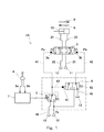
  • the control valve 3 is connected to the main pressure source 11 through a supply line 21 and is connected to the tank 13 through a tank line 22.
  • the control valve 3 connects a neutral position where all the lines 21 to 24 connected to the control valve 3 are blocked, one of the pair of supply / discharge lines 23 and 24 communicates with the supply line 21, and the other communicates with the tank line 22. It is driven between a first position (left side position in FIG. 1) and a second position (right side position in FIG. 1).
  • the control valve 3 may cause the supply / discharge lines 23 and 24 to communicate with the tank line 22 in the neutral position.

Abstract

This hydraulic system is provided with: a control valve that has a first pilot port for operating an actuator in a first direction and a second pilot port for operating the actuator in a second direction; a first line that connects a pilot pressure source and the first pilot port; an electromagnetic proportional valve that is provided in the first line; a second line that branches from the first line further upstream than the electromagnetic proportional valve and connects to the second pilot port; a switching valve that is provided in the second line and has a spring for maintaining a closed position in which the second pilot port communicates with a tank, and a pilot port for shifting from the closed position to an open position in which the second pilot port communicates with the pilot pressure source; and a third line that connects a portion downstream of the electromagnetic proportional valve in the first line with the pilot port of the switching valve.

Description

油圧システムHydraulic system
 本発明は、双方向に作動する油圧アクチュエータを含む油圧システムに関する。 The present invention relates to a hydraulic system including a hydraulic actuator that operates in both directions.
 一般的に、双方向に作動する油圧アクチュエータを電気的に制御する油圧システムでは、油圧アクチュエータと接続された、第1および第2パイロットポートを有する制御弁と、それらの第1および第2パイロットポートへ二次圧を出力する一対の電磁比例弁とが用いられる(例えば、特許文献1参照)。 In general, in a hydraulic system that electrically controls a hydraulic actuator that operates in both directions, a control valve having first and second pilot ports connected to the hydraulic actuator and the first and second pilot ports thereof. A pair of electromagnetic proportional valves that output the secondary pressure is used (see, for example, Patent Document 1).
特開2011-117316号公報JP 2011-117316 A
 しかしながら、一対の電磁比例弁を用いた場合には、油圧回路のコストが高くなる。また、電磁比例弁を制御する制御装置の電流発生装置も2つ必要となるので、制御装置のコストも高い。さらに、制御装置と電磁比例弁とを接続するコネクタのピン数が多いため、大型のコネクタが必要である。 However, when a pair of electromagnetic proportional valves is used, the cost of the hydraulic circuit increases. In addition, since two current generators for the control device for controlling the electromagnetic proportional valve are required, the cost of the control device is high. Furthermore, since there are many pins of the connector which connects a control apparatus and an electromagnetic proportional valve, a large sized connector is required.
 そこで、本発明は、双方向に作動する油圧アクチュエータを単一の電磁比例弁を用いて電気的に制御することができる油圧システムを提供することを目的とする。 Therefore, an object of the present invention is to provide a hydraulic system capable of electrically controlling a hydraulic actuator that operates in both directions using a single electromagnetic proportional valve.
 前記課題を解決するために、本発明の油圧システムは、油圧アクチュエータと接続された、前記アクチュエータを第1方向に作動させるための第1パイロットポートおよび前記アクチュエータを第2方向に作動させるための第2パイロットポートを有する制御弁と、パイロット圧力源と前記第1パイロットポートとを接続する第1ラインと、前記第1ラインに設けられた電磁比例弁と、前記電磁比例弁よりも上流側で前記第1ラインから分岐して前記第2パイロットポートにつながる第2ラインと、前記第2ラインに設けられた、前記第2パイロットポートをタンクと連通させる閉位置と前記第2パイロットポートを前記パイロット圧力源と連通させる開位置との間でシフトする切換弁であって、前記閉位置への維持用のバネおよび前記閉位置から前記開位置へのシフト用のパイロットポートを有する切換弁と、前記第1ラインにおける前記電磁比例弁よりも下流側部分と前記切換弁のパイロットポートとを接続する第3ラインと、を備える、ことを特徴とする。 In order to solve the above problems, a hydraulic system according to the present invention includes a first pilot port connected to a hydraulic actuator for operating the actuator in a first direction and a first pilot port for operating the actuator in a second direction. A control valve having two pilot ports, a first line connecting a pilot pressure source and the first pilot port, an electromagnetic proportional valve provided in the first line, and the upstream side of the electromagnetic proportional valve A second line branched from the first line and connected to the second pilot port; a closed position provided in the second line for communicating the second pilot port with the tank; and the second pilot port as the pilot pressure. A switching valve that shifts between an open position that communicates with a source, the spring for maintaining the closed position and the closing valve A switching valve having a pilot port for shifting from a position to the open position, and a third line connecting the downstream portion of the first line with respect to the electromagnetic proportional valve and the pilot port of the switching valve. It is characterized by that.
 上記の構成によれば、切換弁は、電磁比例弁の二次圧が低いときは閉位置に位置し、電磁比例弁の二次圧が高いときは開位置に位置する。切換弁が閉位置に位置するときは制御弁が電磁比例弁の二次圧によってアクチュエータを第1方向に作動させる第1位置へ駆動され、切換弁が開位置に位置するときは制御弁がパイロット圧力源の圧力と電磁比例弁の二次圧との差圧によってアクチュエータを第2方向に作動させる第2位置へ駆動される。従って、双方向に作動する油圧アクチュエータを単一の電磁比例弁を用いて電気的に制御することができる。しかも、切換弁は、電磁比例弁の二次圧によって自動的に動作するので、制御装置の電流発生装置は1つの制御弁に対して1つだけでよい。従って、制御装置のコストを低減することができる。さらに、1つの制御弁に対する電磁比例弁の数が1つとなるため、制御装置と電磁比例弁とを接続するコネクタのピン数が少ない。従って、小型のコネクタを使用することができ、この点でもコストダウンを図ることができる。 According to the above configuration, the switching valve is located in the closed position when the secondary pressure of the electromagnetic proportional valve is low, and is located in the open position when the secondary pressure of the electromagnetic proportional valve is high. When the switching valve is in the closed position, the control valve is driven to the first position to actuate the actuator in the first direction by the secondary pressure of the electromagnetic proportional valve. When the switching valve is in the open position, the control valve is a pilot. The actuator is driven to the second position for operating the actuator in the second direction by the differential pressure between the pressure of the pressure source and the secondary pressure of the electromagnetic proportional valve. Therefore, a hydraulic actuator that operates in both directions can be electrically controlled using a single electromagnetic proportional valve. Moreover, since the switching valve automatically operates according to the secondary pressure of the electromagnetic proportional valve, only one current generator of the control device is required for one control valve. Therefore, the cost of the control device can be reduced. Furthermore, since the number of electromagnetic proportional valves for one control valve is one, the number of pins of the connector connecting the control device and the electromagnetic proportional valve is small. Therefore, a small connector can be used, and the cost can be reduced also in this respect.
 前記切換弁は、当該切換弁のパイロットポートに導かれる圧力が所定圧力以上となったときに前記閉位置から前記開位置にシフトするように構成されており、前記所定圧力は、前記パイロット圧力源の圧力の半分であってもよい。この構成によれば、アクチュエータを第1方向に作動させるときと第2方向に作動させるときとで制御弁をほぼ同様に駆動することができる。 The switching valve is configured to shift from the closed position to the open position when a pressure guided to a pilot port of the switching valve becomes equal to or higher than a predetermined pressure, and the predetermined pressure is the pilot pressure source. It may be half of the pressure. According to this configuration, the control valve can be driven in substantially the same manner when the actuator is operated in the first direction and when the actuator is operated in the second direction.
 前記電磁比例弁は、指令電流と正の相関を示す二次圧を出力する正比例型であってもよい。この構成によれば、電気系統の寸断等のフェール時に制御弁の第1および第2パイロットポートの圧力をゼロとすることができ、アクチュエータの作動を確実に禁止することができる。 The electromagnetic proportional valve may be a direct proportional type that outputs a secondary pressure having a positive correlation with the command current. According to this configuration, the pressures of the first and second pilot ports of the control valve can be made zero at the time of failure such as disconnection of the electric system, and the operation of the actuator can be surely prohibited.
 上記の油圧システムは、前記アクチュエータを前記第1方向に作動させるための第1操作および前記アクチュエータを前記第2方向に作動させるための第2操作を受ける操作装置であって、前記第1操作の大きさに応じた第1操作信号および前記第2操作の大きさに応じた第2操作信号を出力する操作装置と、前記電磁比例弁へ指令電流を送給する制御装置と、をさらに備え、前記制御装置は、前記第1操作信号が増加するときは前記電磁比例弁から出力される二次圧が前記所定圧力となる基準電流に向かって前記指令電流を増加させ、前記第2操作信号が増加するときは前記基準電流に向かって前記指令電流を低下させてもよい。この構成によれば、アクチュエータを第1操作および第2操作の大きさに準じて作動させることができる。 The hydraulic system is an operating device that receives a first operation for operating the actuator in the first direction and a second operation for operating the actuator in the second direction. An operation device that outputs a first operation signal according to the magnitude and a second operation signal according to the magnitude of the second operation, and a control device that sends a command current to the electromagnetic proportional valve, When the first operation signal increases, the control device increases the command current toward a reference current at which a secondary pressure output from the electromagnetic proportional valve becomes the predetermined pressure, and the second operation signal is When increasing, the command current may be decreased toward the reference current. According to this configuration, the actuator can be operated according to the magnitudes of the first operation and the second operation.
 前記第1操作信号が最大となったときの前記指令電流は前記基準電流よりも小さく、前記第2操作信号が最大となったときの前記指令電流は前記基準電流よりも大きくてもよい。この構成によれば、所定圧力の近傍での切換弁の不安定な動作を回避することができる。 The command current when the first operation signal becomes maximum may be smaller than the reference current, and the command current when the second operation signal becomes maximum may be larger than the reference current. According to this configuration, an unstable operation of the switching valve in the vicinity of the predetermined pressure can be avoided.
 例えば、前記操作装置は、操作レバーを含み、前記第1操作信号および前記第2操作信号は、前記操作レバーの傾倒角を表してもよい。 For example, the operation device may include an operation lever, and the first operation signal and the second operation signal may represent an inclination angle of the operation lever.
 本発明によれば、双方向に作動する油圧アクチュエータを単一の電磁比例弁を用いて電気的に制御することができる。 According to the present invention, a hydraulic actuator that operates in both directions can be electrically controlled using a single electromagnetic proportional valve.
本発明の第1実施形態に係る油圧システムの概略構成図である。1 is a schematic configuration diagram of a hydraulic system according to a first embodiment of the present invention. 図2Aは制御装置から電磁比例弁へ出力される指令電流と第1パイロットポートの圧力との関係を示すグラフ、図2Bは前記指令電流と第2パイロットポートの圧力との関係を示すグラフ、図2Cは前記指令電流と制御弁に作用する駆動圧力との関係を示すグラフである。2A is a graph showing the relationship between the command current output from the control device to the electromagnetic proportional valve and the pressure of the first pilot port, FIG. 2B is a graph showing the relationship between the command current and the pressure of the second pilot port, FIG. 2C is a graph showing the relationship between the command current and the driving pressure acting on the control valve. 第1および第2操作と前記指令電流との関係を示すグラフである。It is a graph which shows the relationship between 1st and 2nd operation and the said command electric current. 本発明の第2実施形態に係る油圧システムの概略構成図である。It is a schematic block diagram of the hydraulic system which concerns on 2nd Embodiment of this invention. 本発明の第3実施形態に係る油圧システムの概略構成図である。It is a schematic block diagram of the hydraulic system which concerns on 3rd Embodiment of this invention.
 (第1実施形態)
 図1に、本発明の第1実施形態に係る油圧システム1Aを示す。この油圧システム1Aは、双方向(第1方向Aおよび第2方向B)に作動する油圧アクチュエータ15と、一対の給排ライン23,24によりアクチュエータ15と接続された制御弁3と、操縦者により操作される操作装置8を含む。
(First embodiment)
FIG. 1 shows a hydraulic system 1A according to the first embodiment of the present invention. The hydraulic system 1A includes a hydraulic actuator 15 that operates in both directions (first direction A and second direction B), a control valve 3 connected to the actuator 15 by a pair of supply / discharge lines 23 and 24, and a driver. The operating device 8 to be operated is included.
 図例では、アクチュエータ15が油圧シリンダであり、第1方向Aは伸長方向、第2方向は短縮方向である。ただし、アクチュエータ15は、油圧シリンダに限られるものではなく、例えば時計回りおよび反時計回りに回転する油圧モータであってもよい。 In the illustrated example, the actuator 15 is a hydraulic cylinder, the first direction A is the extension direction, and the second direction is the shortening direction. However, the actuator 15 is not limited to a hydraulic cylinder, and may be, for example, a hydraulic motor that rotates clockwise and counterclockwise.
 制御弁3は、供給ライン21により主圧力源11と接続されているとともに、タンクライン22によりタンク13と接続されている。制御弁3は、当該制御弁3につながる全てのライン21~24をブロックする中立位置と、一対の給排ライン23,24の一方を供給ライン21と連通させ、他方をタンクライン22と連通する第1位置(図1の左側位置)および第2位置(図1の右側位置)との間で駆動される。なお、アクチュエータ15の用途によっては、制御弁3は、中立位置で給排ライン23,24をタンクライン22と連通させてもよい。 The control valve 3 is connected to the main pressure source 11 through a supply line 21 and is connected to the tank 13 through a tank line 22. The control valve 3 connects a neutral position where all the lines 21 to 24 connected to the control valve 3 are blocked, one of the pair of supply / discharge lines 23 and 24 communicates with the supply line 21, and the other communicates with the tank line 22. It is driven between a first position (left side position in FIG. 1) and a second position (right side position in FIG. 1). Depending on the application of the actuator 15, the control valve 3 may cause the supply / discharge lines 23 and 24 to communicate with the tank line 22 in the neutral position.
 より詳しくは、制御弁3は、当該制御弁3を中立位置から第1位置に移動させてアクチュエータ15を第1方向Aに作動させるための第1パイロットポート3aと、当該制御弁3を中立位置から第2位置に移動させてアクチュエータ15を第2方向Bに作動させるための第2パイロットポート3bを有する。 More specifically, the control valve 3 includes a first pilot port 3a for moving the control valve 3 from the neutral position to the first position to operate the actuator 15 in the first direction A, and the control valve 3 at the neutral position. The second pilot port 3b for moving the actuator 15 in the second direction B by moving from the first position to the second position.
 第1パイロットポート3aは、第1ライン41によりパイロット圧力源12と接続されている。第1ライン41には、電磁比例弁5が設けられている。つまり、第1パイロットポート3aには、電磁比例弁5から出力される二次圧が導かれる。電磁比例弁5は、タンクライン44によりタンク13と接続されている。 The first pilot port 3 a is connected to the pilot pressure source 12 by the first line 41. In the first line 41, an electromagnetic proportional valve 5 is provided. That is, the secondary pressure output from the electromagnetic proportional valve 5 is guided to the first pilot port 3a. The electromagnetic proportional valve 5 is connected to the tank 13 by a tank line 44.
 電磁比例弁5へは、制御装置7から指令電流Iが送給される。本実施形態では、電磁比例弁5が、図2Aに示すように、指令電流Iと正の相関を示す二次圧を出力する正比例型である。なお、電磁比例弁5から出力される二次圧、換言すれば第1パイロットポート3aに導かれる圧力Paの最大値は、パイロット圧力源12の圧力Ppと等しい。図2A中のI1は電磁比例弁5から二次圧が出力され始めるときの最低電流であり、I2は電磁比例弁5の二次圧が最大となる最高電流である。 The command current I is supplied from the control device 7 to the electromagnetic proportional valve 5. In this embodiment, as shown in FIG. 2A, the electromagnetic proportional valve 5 is a direct proportional type that outputs a secondary pressure having a positive correlation with the command current I. The secondary pressure output from the electromagnetic proportional valve 5, in other words, the maximum value of the pressure Pa guided to the first pilot port 3 a is equal to the pressure Pp of the pilot pressure source 12. In FIG. 2A, I1 is the lowest current when the secondary pressure starts to be output from the electromagnetic proportional valve 5, and I2 is the highest current at which the secondary pressure of the electromagnetic proportional valve 5 becomes maximum.
 図1に戻って、第1ライン41からは、電磁比例弁5よりも上流側で第2ライン42が分岐しており、この第2ライン42は、第2パイロットポート3bにつながっている。第2ライン42には、切換弁6が設けられている。切換弁6は、タンクライン45によりタンク13と接続されている。 Referring back to FIG. 1, a second line 42 branches from the first line 41 upstream of the electromagnetic proportional valve 5, and the second line 42 is connected to the second pilot port 3b. A switching valve 6 is provided in the second line 42. The switching valve 6 is connected to the tank 13 by a tank line 45.
 切換弁6は、第2パイロットポート3bをタンク13と連通させる閉位置と、第2パイロットポート3bをパイロット圧力源12と連通させる開位置との間でシフトする。本実施形態では、切換弁6が、パイロット弁であり、閉位置への維持用のバネ62と、閉位置から開位置へのシフト用のパイロットポート61を有する。このパイロットポート61は、第3ライン43により、第1ライン41における電磁比例弁5よりも下流側部分と接続されている。 The switching valve 6 shifts between a closed position where the second pilot port 3b communicates with the tank 13 and an open position where the second pilot port 3b communicates with the pilot pressure source 12. In this embodiment, the switching valve 6 is a pilot valve, and has a spring 62 for maintaining the closed position and a pilot port 61 for shifting from the closed position to the open position. The pilot port 61 is connected to the downstream portion of the first line 41 with respect to the electromagnetic proportional valve 5 by the third line 43.
 切換弁6は、配管がつながれる単独の弁であってもよい。しかし、図1に二点鎖線で示すように、切換弁6は、電磁比例弁5と共に1つのハウジング内に形成されてもよい。この場合、そのハウジングに、第1ライン41の一部(電磁比例弁5の近傍部分)、第2ライン42の上流側部分および第3ライン43も形成される。このような構成であれば、そのハウジングを含むパイロット弁ユニットを制御弁3に容易に装着することができる。 The switching valve 6 may be a single valve to which piping is connected. However, as indicated by a two-dot chain line in FIG. 1, the switching valve 6 may be formed in one housing together with the electromagnetic proportional valve 5. In this case, a part of the first line 41 (a part near the electromagnetic proportional valve 5), an upstream part of the second line 42, and a third line 43 are also formed in the housing. With such a configuration, the pilot valve unit including the housing can be easily attached to the control valve 3.
 切換弁6は、当該切換弁6のパイロットポート61に導かれる圧力、換言すれば電磁比例弁5から出力される二次圧が所定圧力α以上となったときに、閉位置から開位置にシフトするように構成されている。このため、図2Bに示すように、第2パイロットポート3bの圧力Pbは、指令電流Iが電磁比例弁5から出力される二次圧が所定圧力αとなる基準電流I0未満の場合はゼロであり、指令電流が基準電流I0以上のときはパイロット圧力源12の圧力Ppとなる。 The switching valve 6 shifts from the closed position to the opened position when the pressure guided to the pilot port 61 of the switching valve 6, in other words, the secondary pressure output from the electromagnetic proportional valve 5 becomes equal to or higher than the predetermined pressure α. Is configured to do. For this reason, as shown in FIG. 2B, the pressure Pb of the second pilot port 3b is zero when the command current I is less than the reference current I0 at which the secondary pressure output from the electromagnetic proportional valve 5 becomes the predetermined pressure α. Yes, when the command current is equal to or greater than the reference current I0, the pressure Pp of the pilot pressure source 12 is obtained.
 従って、制御弁3には、図2Cに示すように、指令電流Iが基準電流I0未満の場合は、当該制御弁3を第1位置へ駆動させる駆動圧力として、電磁比例弁5の二次圧が作用する。一方、指令電流Iが基準電流I0以上の場合は、当該制御弁3を第2位置へ駆動させる駆動圧力として、パイロット圧力源12の圧力Ppと電磁比例弁5の二次圧の差圧が作用する。 Therefore, as shown in FIG. 2C, when the command current I is less than the reference current I0, the control valve 3 has a secondary pressure of the electromagnetic proportional valve 5 as a driving pressure for driving the control valve 3 to the first position. Act. On the other hand, when the command current I is equal to or greater than the reference current I0, a differential pressure between the pressure Pp of the pilot pressure source 12 and the secondary pressure of the electromagnetic proportional valve 5 acts as a driving pressure for driving the control valve 3 to the second position. To do.
 本実施形態では、切換弁6を閉位置から開位置にシフトさせる所定圧力αは、パイロット圧力源12の圧力Ppの半分である。ここで、「半分」とは、Pp/2と実質的に等しい範囲(Pp/2からそれの±20%の範囲)をいう。このため、図2Cに示すように、制御弁3に作用する駆動圧力はI1~I0とI0~I2とでほぼ対称となる。換言すれば、アクチュエータ15を第1方向に作動させるときと第2方向に作動させるときとで制御弁3をほぼ同様に駆動することができる。 In the present embodiment, the predetermined pressure α that shifts the switching valve 6 from the closed position to the open position is half of the pressure Pp of the pilot pressure source 12. Here, “half” refers to a range substantially equal to Pp / 2 (a range of ± 20% from Pp / 2). For this reason, as shown in FIG. 2C, the driving pressure acting on the control valve 3 is substantially symmetrical between I1 to I0 and I0 to I2. In other words, the control valve 3 can be driven in substantially the same manner when the actuator 15 is operated in the first direction and when it is operated in the second direction.
 図1に戻って、電磁比例弁5に指令電流Iを送給する制御装置7には、上述した操作装置8が接続されている。操作装置8は、アクチュエータ15を第1方向Aに作動させるための第1操作と、アクチュエータ15を第2方向Bに作動させるための第2操作を受ける。そして、操作装置8は、第1操作の大きさに応じた第1操作信号Saおよび第2操作の大きさに応じた第2操作信号sbを制御装置7へ出力する。 Returning to FIG. 1, the above-described operation device 8 is connected to the control device 7 that supplies the command current I to the electromagnetic proportional valve 5. The operating device 8 receives a first operation for operating the actuator 15 in the first direction A and a second operation for operating the actuator 15 in the second direction B. Then, the controller device 8 outputs a first operation signal Sa corresponding to the magnitude of the first operation and a second operation signal sb corresponding to the magnitude of the second operation to the control device 7.
 操作装置8は、例えば、操作レバーを含む電気ジョイスティックである。この場合、第1操作信号Saおよび第2操作信号Sbは、操作レバーの傾倒角を表す。ただし、操作装置8は、例えば、操作レバーが一方に傾倒されたときに操作レバーの傾倒角に応じた第1パイロット圧を出力し、操作レバーが他方に傾倒されたときに操作レバーの傾倒角に応じた第2パイロット圧を出力する操作弁であってもよい。この場合、第1および第2パイロット圧を計測する一対の圧力センサが設けられ、計測された第1および第2パイロット圧が制御装置7に入力されてもよい。あるいは、操作装置8は、操作レバーを含むものに限らず、例えば、第1操作および第2操作として回転操作を受けるハンドルを含むものであってもよい。 The operating device 8 is, for example, an electric joystick including an operating lever. In this case, the first operation signal Sa and the second operation signal Sb represent the tilt angle of the operation lever. However, the controller 8 outputs, for example, a first pilot pressure corresponding to the tilt angle of the control lever when the control lever is tilted to one side, and the tilt angle of the control lever when the control lever is tilted to the other side. It may be an operation valve that outputs a second pilot pressure according to the above. In this case, a pair of pressure sensors that measure the first and second pilot pressures may be provided, and the measured first and second pilot pressures may be input to the control device 7. Alternatively, the operation device 8 is not limited to the one including the operation lever, and may include, for example, a handle that receives a rotation operation as the first operation and the second operation.
 制御装置7は、操作装置8から第1操作信号Saおよび第2操作信号Sbが出力されないときは電磁比例弁5へ指令電流Iを送給しない。一方、操作装置8から第1操作信号Saが出力されるときは、制御装置7は、図3に示すように第1操作信号Saに応じて電磁比例弁5へ指令電流Iを送給する。操作装置8から第2操作信号Sbが出力されるときは、制御装置7は、図3に示すように第2操作信号Sbに応じて電磁比例弁5へ指令電流Iを送給する。このため、切換弁6は、アクチュエータ15を作動させないときおよびアクチュエータ15を第1方向Aに作動させるときに閉位置に位置し、アクチュエータ15を第2方向Bに作動させるときに開位置に位置する。 The control device 7 does not send the command current I to the electromagnetic proportional valve 5 when the first operation signal Sa and the second operation signal Sb are not output from the operation device 8. On the other hand, when the first operation signal Sa is output from the operation device 8, the control device 7 sends a command current I to the electromagnetic proportional valve 5 in accordance with the first operation signal Sa as shown in FIG. 3. When the second operation signal Sb is output from the operation device 8, the control device 7 supplies a command current I to the electromagnetic proportional valve 5 in accordance with the second operation signal Sb as shown in FIG. Therefore, the switching valve 6 is located at the closed position when the actuator 15 is not operated and when the actuator 15 is operated in the first direction A, and is located at the open position when the actuator 15 is operated in the second direction B. .
 より詳しくは、制御装置7は、第1操作信号Saが増加するときは最低電流I1から基準電流I0に向かって指令電流Iを増加させ、第2操作信号Sbが増加するときは最高電流I2から基準電流I0に向かって指令電流Iを低下させる。これにより、アクチュエータ15を第1操作および第2操作の大きさに準じて作動させることができる。 More specifically, the control device 7 increases the command current I from the lowest current I1 toward the reference current I0 when the first operation signal Sa increases, and from the highest current I2 when the second operation signal Sb increases. The command current I is reduced toward the reference current I0. Thereby, the actuator 15 can be operated according to the magnitude | size of 1st operation and 2nd operation.
 なお、第1操作信号Saが最大S1となったときの指令電流I3は基準電流I0よりも小さく、第2操作信号Sbが最大S2となったときの指令電流I4は基準電流I0よりも大きいことが望ましい。切換弁6を閉位置から開位置へシフトさせる所定圧力αの近傍での切換弁6の不安定な動作を回避することができるからである。 The command current I3 when the first operation signal Sa reaches the maximum S1 is smaller than the reference current I0, and the command current I4 when the second operation signal Sb reaches the maximum S2 is greater than the reference current I0. Is desirable. This is because an unstable operation of the switching valve 6 in the vicinity of the predetermined pressure α that shifts the switching valve 6 from the closed position to the open position can be avoided.
 以上説明したように、本実施形態の油圧システム1Aでは、切換弁6が、電磁比例弁5の二次圧が低いときは閉位置に位置し、電磁比例弁5の二次圧が高いときは開位置に位置する。切換弁6が閉位置に位置するときは制御弁3が電磁比例弁5の二次圧によって第1位置へ駆動され、切換弁6が開位置に位置するときは制御弁3がパイロット圧力源12の圧力Ppと電磁比例弁5の二次圧との差圧によって第2位置へ駆動される。従って、双方向に作動する油圧アクチュエータ15を単一の電磁比例弁5を用いて電気的に制御することができる。しかも、切換弁6は、電磁比例弁5の二次圧によって自動的に動作するので、制御装置7の電流発生装置は1つの制御弁3に対して1つだけでよい。従って、制御装置7のコストを低減することができる。さらに、1つの制御弁3に対する電磁比例弁5の数が1つとなるため、制御装置7と電磁比例弁5とを接続するコネクタのピン数が少ない。従って、小型のコネクタを使用することができ、この点でもコストダウンを図ることができる。 As described above, in the hydraulic system 1A of the present embodiment, the switching valve 6 is located at the closed position when the secondary pressure of the electromagnetic proportional valve 5 is low, and when the secondary pressure of the electromagnetic proportional valve 5 is high. Located in the open position. When the switching valve 6 is in the closed position, the control valve 3 is driven to the first position by the secondary pressure of the electromagnetic proportional valve 5, and when the switching valve 6 is in the open position, the control valve 3 is in the pilot pressure source 12. Is driven to the second position by the differential pressure between the pressure Pp of the pressure and the secondary pressure of the electromagnetic proportional valve 5. Therefore, the hydraulic actuator 15 that operates in both directions can be electrically controlled using the single electromagnetic proportional valve 5. Moreover, since the switching valve 6 automatically operates according to the secondary pressure of the electromagnetic proportional valve 5, only one current generator for the control device 7 is required for one control valve 3. Therefore, the cost of the control device 7 can be reduced. Furthermore, since the number of the electromagnetic proportional valves 5 for one control valve 3 is one, the number of pins of the connector connecting the control device 7 and the electromagnetic proportional valve 5 is small. Therefore, a small connector can be used, and the cost can be reduced also in this respect.
 さらに、本実施形態では、電磁比例弁5が正比例型であり、切換弁6が通常は閉位置に維持されるので、電気系統の寸断等のフェール時に制御弁3の第1パイロットポート3aの圧力Paおよび第2パイロットポート3bの圧力Pbをゼロとすることができ、アクチュエータ15の作動を確実に禁止することができる。 Further, in the present embodiment, the electromagnetic proportional valve 5 is a direct proportional type, and the switching valve 6 is normally maintained at the closed position. Pa and the pressure Pb of the second pilot port 3b can be made zero, and the operation of the actuator 15 can be reliably prohibited.
 (第2実施形態)
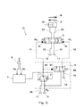
 次に、図4を参照して、本発明の第2実施形態に係る油圧システム1Bを説明する。なお、本実施形態ならびに後述する第3実施形態において、第1実施形態と同一構成要素には同一符号を付し、重複した説明は省略する。
(Second Embodiment)
Next, a hydraulic system 1B according to a second embodiment of the present invention will be described with reference to FIG. In the present embodiment and the third embodiment to be described later, the same components as those in the first embodiment are denoted by the same reference numerals, and redundant description is omitted.
 本実施形態では、切換弁6に、当該切換弁6が閉位置から開位置にシフトしたときに当該切換弁6を開位置に保持することをアシストするためのアシスト流路63が設けられている。ただし、アシスト流路63による押付力は、切換弁6を開位置から閉位置へ戻すためのバネ62の付勢力よりも十分に小さいことが望ましい。 In the present embodiment, the switching valve 6 is provided with an assist flow path 63 for assisting in holding the switching valve 6 in the open position when the switching valve 6 is shifted from the closed position to the open position. . However, it is desirable that the pressing force by the assist flow path 63 is sufficiently smaller than the urging force of the spring 62 for returning the switching valve 6 from the open position to the closed position.
 このような構成であれば、第1実施形態と同様の効果に加え、開位置にシフトした切換弁6を開位置に安定的に維持することができるという効果を得ることができる。 With such a configuration, in addition to the same effects as in the first embodiment, it is possible to obtain the effect that the switching valve 6 shifted to the open position can be stably maintained in the open position.
 (第3実施形態)
 次に、図5を参照して、本発明の第3実施形態に係る油圧システム1Cを説明する。本実施形態では、電磁比例弁5が指令電流Iと二次圧が負の相関を示す逆比例型である。
(Third embodiment)
Next, a hydraulic system 1C according to a third embodiment of the present invention will be described with reference to FIG. In the present embodiment, the electromagnetic proportional valve 5 is an inverse proportional type in which the command current I and the secondary pressure have a negative correlation.
 本実施形態でも、フェール時以外は第1実施形態と同様の効果を得ることができる。フェール時には、制御弁3の第1パイロットポート3aの圧力Paおよび第2パイロットポート3bの圧力Pbが共にパイロット圧力源12の圧力Ppとなり、アクチュエータ15の作動が禁止される。 Also in this embodiment, the same effects as in the first embodiment can be obtained except during a failure. During a failure, the pressure Pa of the first pilot port 3a and the pressure Pb of the second pilot port 3b of the control valve 3 both become the pressure Pp of the pilot pressure source 12, and the operation of the actuator 15 is prohibited.
 (その他の実施形態)
 本発明は上述した第1~第3実施形態に限定されるものではなく、本発明の要旨を逸脱しない範囲で種々の変形が可能である。
(Other embodiments)
The present invention is not limited to the first to third embodiments described above, and various modifications can be made without departing from the scope of the present invention.
 例えば、第3実施形態において、第2実施形態同様、切換弁6に、当該切換弁6が閉位置から開位置にシフトしたときに当該切換弁6を開位置に保持することをアシストするためのアシスト流路63が設けられてもよい。ただし、アシスト流路63による押付力は、切換弁6を開位置から閉位置へ戻すためのバネ62の付勢力よりも十分に小さいことが望ましい。 For example, in the third embodiment, similar to the second embodiment, the switching valve 6 is assisted to hold the switching valve 6 in the open position when the switching valve 6 is shifted from the closed position to the open position. An assist channel 63 may be provided. However, it is desirable that the pressing force by the assist flow path 63 is sufficiently smaller than the urging force of the spring 62 for returning the switching valve 6 from the open position to the closed position.
 1A~1C 油圧システム
 12 パイロット圧力源
 15 油圧アクチュエータ
 3  制御弁
 3a 第1パイロットポート
 3b 第2パイロットポート
 41 第1ライン
 42 第2ライン
 43 第3ライン
 5  電磁比例弁
 6  切換弁
 61 パイロットポート
 62 バネ
 7  制御装置
 8  操作装置
1A to 1C Hydraulic system 12 Pilot pressure source 15 Hydraulic actuator 3 Control valve 3a 1st pilot port 3b 2nd pilot port 41 1st line 42 2nd line 43 3rd line 5 Solenoid proportional valve 6 Switching valve 61 Pilot port 62 Spring 7 Control device 8 Operating device

Claims (6)

  1.  油圧アクチュエータと接続された、前記アクチュエータを第1方向に作動させるための第1パイロットポートおよび前記アクチュエータを第2方向に作動させるための第2パイロットポートを有する制御弁と、
     パイロット圧力源と前記第1パイロットポートとを接続する第1ラインと、
     前記第1ラインに設けられた電磁比例弁と、
     前記電磁比例弁よりも上流側で前記第1ラインから分岐して前記第2パイロットポートにつながる第2ラインと、
     前記第2ラインに設けられた、前記第2パイロットポートをタンクと連通させる閉位置と前記第2パイロットポートを前記パイロット圧力源と連通させる開位置との間でシフトする切換弁であって、前記閉位置への維持用のバネおよび前記閉位置から前記開位置へのシフト用のパイロットポートを有する切換弁と、
     前記第1ラインにおける前記電磁比例弁よりも下流側部分と前記切換弁のパイロットポートとを接続する第3ラインと、
    を備える、油圧システム。
    A control valve connected to a hydraulic actuator and having a first pilot port for operating the actuator in a first direction and a second pilot port for operating the actuator in a second direction;
    A first line connecting a pilot pressure source and the first pilot port;
    An electromagnetic proportional valve provided in the first line;
    A second line branched from the first line upstream of the electromagnetic proportional valve and connected to the second pilot port;
    A switching valve provided in the second line that shifts between a closed position for communicating the second pilot port with a tank and an open position for communicating the second pilot port with the pilot pressure source; A switching valve having a spring for maintaining the closed position and a pilot port for shifting from the closed position to the open position;
    A third line connecting the downstream portion of the first line with respect to the electromagnetic proportional valve and the pilot port of the switching valve;
    Comprising a hydraulic system.
  2.  前記切換弁は、当該切換弁のパイロットポートに導かれる圧力が所定圧力以上となったときに前記閉位置から前記開位置にシフトするように構成されており、
     前記所定圧力は、前記パイロット圧力源の圧力の半分である、請求項1に記載の油圧システム。
    The switching valve is configured to shift from the closed position to the open position when the pressure guided to the pilot port of the switching valve is equal to or higher than a predetermined pressure.
    The hydraulic system according to claim 1, wherein the predetermined pressure is half of the pressure of the pilot pressure source.
  3.  前記電磁比例弁は、指令電流と正の相関を示す二次圧を出力する正比例型である、請求項2に記載の油圧システム。 The hydraulic system according to claim 2, wherein the electromagnetic proportional valve is a direct proportional type that outputs a secondary pressure having a positive correlation with a command current.
  4.  前記アクチュエータを前記第1方向に作動させるための第1操作および前記アクチュエータを前記第2方向に作動させるための第2操作を受ける操作装置であって、前記第1操作の大きさに応じた第1操作信号および前記第2操作の大きさに応じた第2操作信号を出力する操作装置と、
     前記電磁比例弁へ指令電流を送給する制御装置と、をさらに備え、
     前記制御装置は、前記第1操作信号が増加するときは前記電磁比例弁から出力される二次圧が前記所定圧力となる基準電流に向かって前記指令電流を増加させ、前記第2操作信号が増加するときは前記基準電流に向かって前記指令電流を低下させる、請求項3に記載の油圧システム。
    An operating device that receives a first operation for operating the actuator in the first direction and a second operation for operating the actuator in the second direction, the operating device according to a magnitude of the first operation An operation device for outputting a first operation signal and a second operation signal corresponding to the magnitude of the second operation;
    A control device for supplying a command current to the electromagnetic proportional valve,
    When the first operation signal increases, the control device increases the command current toward a reference current at which a secondary pressure output from the electromagnetic proportional valve becomes the predetermined pressure, and the second operation signal is The hydraulic system according to claim 3, wherein the command current is decreased toward the reference current when increasing.
  5.  前記第1操作信号が最大となったときの前記指令電流は前記基準電流よりも小さく、前記第2操作信号が最大となったときの前記指令電流は前記基準電流よりも大きい、請求項4に記載の油圧システム。 The command current when the first operation signal becomes maximum is smaller than the reference current, and the command current when the second operation signal becomes maximum is larger than the reference current. The described hydraulic system.
  6.  前記操作装置は、操作レバーを含み、前記第1操作信号および前記第2操作信号は、前記操作レバーの傾倒角を表す、請求項4または5に記載の油圧システム。 The hydraulic system according to claim 4 or 5, wherein the operation device includes an operation lever, and the first operation signal and the second operation signal represent an inclination angle of the operation lever.
PCT/JP2016/001229 2015-03-13 2016-03-07 Hydraulic system WO2016147596A1 (en)

Priority Applications (3)

Application Number Priority Date Filing Date Title
US15/557,911 US10107312B2 (en) 2015-03-13 2016-03-07 Hydraulic system
GB1716700.8A GB2553967B (en) 2015-03-13 2016-03-07 Hydraulic system
CN201680015068.4A CN107429715B (en) 2015-03-13 2016-03-07 Oil hydraulic system

Applications Claiming Priority (2)

Application Number Priority Date Filing Date Title
JP2015050466A JP6475522B2 (en) 2015-03-13 2015-03-13 Hydraulic system
JP2015-050466 2015-03-13

Publications (1)

Publication Number Publication Date
WO2016147596A1 true WO2016147596A1 (en) 2016-09-22

Family

ID=56918596

Family Applications (1)

Application Number Title Priority Date Filing Date
PCT/JP2016/001229 WO2016147596A1 (en) 2015-03-13 2016-03-07 Hydraulic system

Country Status (5)

Country Link
US (1) US10107312B2 (en)
JP (1) JP6475522B2 (en)
CN (1) CN107429715B (en)
GB (1) GB2553967B (en)
WO (1) WO2016147596A1 (en)

Families Citing this family (5)

* Cited by examiner, † Cited by third party
Publication number Priority date Publication date Assignee Title
JP7002351B2 (en) * 2018-01-25 2022-01-20 川崎重工業株式会社 Hydraulic system
CN109139589B (en) * 2018-09-22 2020-08-04 江苏悦达专用车有限公司 Sectional speed-division motion control system
JP7152968B2 (en) * 2019-02-28 2022-10-13 川崎重工業株式会社 hydraulic excavator drive system
JP7297596B2 (en) * 2019-08-23 2023-06-26 川崎重工業株式会社 Hydraulic system for construction machinery
EP3936969A1 (en) * 2020-07-08 2022-01-12 Manitou Equipment America, LLC Offset control stick system and method

Citations (1)

* Cited by examiner, † Cited by third party
Publication number Priority date Publication date Assignee Title
JPS5934009A (en) * 1982-08-17 1984-02-24 Kayaba Ind Co Ltd Control unit of hydraulic cylinder

Family Cites Families (19)

* Cited by examiner, † Cited by third party
Publication number Priority date Publication date Assignee Title
US4362089A (en) * 1980-06-16 1982-12-07 Caterpillar Tractor Co. Valve system
JPS5723795U (en) * 1981-06-25 1982-02-06
US5060475A (en) * 1990-05-29 1991-10-29 Caterpillar Inc. Pilot control circuit for load sensing hydraulic systems
EP0649988B1 (en) * 1993-05-07 2000-08-16 Hitachi Construction Machinery Co., Ltd. Driving controller of hydraulic machine
AT404291B (en) * 1996-07-10 1998-10-27 Hygrama Ag OSCILLATION VALVE
JP3685923B2 (en) * 1998-04-21 2005-08-24 日立建機株式会社 Pipe break control valve device
CN100392257C (en) * 2003-01-14 2008-06-04 日立建机株式会社 Hydraulic working machine
JP4762022B2 (en) * 2006-03-27 2011-08-31 カヤバ工業株式会社 Energy converter
DE112007002567T5 (en) * 2006-10-31 2009-11-05 Actuant Corp., Butler System and method for a controlled high pressure valve
CN100491748C (en) * 2007-08-01 2009-05-27 太原理工大学 Independent control electrohydraulic system of oil inlet and outlet matching with pump valve composite flux
JP4548494B2 (en) * 2008-02-19 2010-09-22 コベルコ建機株式会社 Hydraulic circuit for construction machinery
JP2009263061A (en) * 2008-04-24 2009-11-12 Ihi Corp Hydraulic circuit for controlling crane
DE102009014421A1 (en) * 2009-03-26 2010-09-30 Abb Technology Ag valve assembly
JP2011117316A (en) 2009-12-01 2011-06-16 Hitachi Constr Mach Co Ltd Control device of construction machine
FI123735B (en) * 2011-01-14 2013-10-15 Parker Hannifin Mfg Finland Oy Directional valve with pressure compensation
US9250632B2 (en) * 2011-12-30 2016-02-02 Sti Srl Valve positioning system with bleed prevention
CN104520595B (en) * 2012-08-16 2016-02-10 沃尔沃建造设备有限公司 For the hydraulic control valve of construction plant
JP2014142032A (en) * 2013-01-25 2014-08-07 Kawasaki Heavy Ind Ltd Hydraulic drive device
JP6149819B2 (en) * 2014-07-30 2017-06-21 コベルコ建機株式会社 Swivel control device for construction machinery

Patent Citations (1)

* Cited by examiner, † Cited by third party
Publication number Priority date Publication date Assignee Title
JPS5934009A (en) * 1982-08-17 1984-02-24 Kayaba Ind Co Ltd Control unit of hydraulic cylinder

Also Published As

Publication number Publication date
GB2553967B (en) 2020-07-29
JP6475522B2 (en) 2019-02-27
GB201716700D0 (en) 2017-11-29
US20180051721A1 (en) 2018-02-22
US10107312B2 (en) 2018-10-23
CN107429715A (en) 2017-12-01
GB2553967A (en) 2018-03-21
JP2016169814A (en) 2016-09-23
CN107429715B (en) 2019-04-09

Similar Documents

Publication Publication Date Title
WO2016147596A1 (en) Hydraulic system
JP6603568B2 (en) Hydraulic drive system
US9249812B2 (en) Hydraulic circuit for pipe layer
JP2005265062A (en) Hydraulic control device for working machine
JP6917871B2 (en) Hydraulic control circuit for construction machinery
JP2008006850A (en) Vehicular brake system
US20130146163A1 (en) Device for controlling construction equipment
WO2016147597A1 (en) Hydraulic drive system for construction machine
US10184499B2 (en) Hydraulic circuit for construction machine
JP2020026828A5 (en)
US10273988B2 (en) Fluid pressure system
JP2013249957A (en) Hydraulic system, and pressure limiting valve
US10119249B2 (en) Control device for confluence flow rate of working device for construction machinery and control method therefor
JP2008534378A (en) Equipment for active roll stabilization
JP2010112494A (en) Cavitation prevention circuit for working machine
JP2010048359A (en) Pump control circuit of construction machine
JP2016089910A (en) Hydraulic drive system of construction equipment
WO2018194091A1 (en) Hydraulic system
JP5015880B2 (en) Pump control circuit for construction machinery
WO2014073551A1 (en) Fluid pressure control device for power shovel
JP2018080771A (en) Position selection device
EP2886878A1 (en) Hydraulic control valve for construction machinery
JP2006103548A (en) Hydraulic brake control device
JP7002351B2 (en) Hydraulic system
JP2010196781A (en) Hydraulic control system

Legal Events

Date Code Title Description
121 Ep: the epo has been informed by wipo that ep was designated in this application

Ref document number: 16764429

Country of ref document: EP

Kind code of ref document: A1

WWE Wipo information: entry into national phase

Ref document number: 15557911

Country of ref document: US

NENP Non-entry into the national phase

Ref country code: DE

ENP Entry into the national phase

Ref document number: 201716700

Country of ref document: GB

Kind code of ref document: A

Free format text: PCT FILING DATE = 20160307

122 Ep: pct application non-entry in european phase

Ref document number: 16764429

Country of ref document: EP

Kind code of ref document: A1