WO2016147483A1 - 採掘ガス圧縮システムの状態監視装置及び状態監視方法、並びに、採掘ガス圧縮システム - Google Patents
採掘ガス圧縮システムの状態監視装置及び状態監視方法、並びに、採掘ガス圧縮システム Download PDFInfo
- Publication number
- WO2016147483A1 WO2016147483A1 PCT/JP2015/082232 JP2015082232W WO2016147483A1 WO 2016147483 A1 WO2016147483 A1 WO 2016147483A1 JP 2015082232 W JP2015082232 W JP 2015082232W WO 2016147483 A1 WO2016147483 A1 WO 2016147483A1
- Authority
- WO
- WIPO (PCT)
- Prior art keywords
- compressor
- mining gas
- compression system
- output
- motor
- Prior art date
- Legal status (The legal status is an assumption and is not a legal conclusion. Google has not performed a legal analysis and makes no representation as to the accuracy of the status listed.)
- Ceased
Links
Images



Classifications
-
- F—MECHANICAL ENGINEERING; LIGHTING; HEATING; WEAPONS; BLASTING
- F04—POSITIVE - DISPLACEMENT MACHINES FOR LIQUIDS; PUMPS FOR LIQUIDS OR ELASTIC FLUIDS
- F04B—POSITIVE-DISPLACEMENT MACHINES FOR LIQUIDS; PUMPS
- F04B49/00—Control, e.g. of pump delivery, or pump pressure of, or safety measures for, machines, pumps, or pumping installations, not otherwise provided for, or of interest apart from, groups F04B1/00 - F04B47/00
- F04B49/06—Control using electricity
- F04B49/065—Control using electricity and making use of computers
-
- F—MECHANICAL ENGINEERING; LIGHTING; HEATING; WEAPONS; BLASTING
- F04—POSITIVE - DISPLACEMENT MACHINES FOR LIQUIDS; PUMPS FOR LIQUIDS OR ELASTIC FLUIDS
- F04B—POSITIVE-DISPLACEMENT MACHINES FOR LIQUIDS; PUMPS
- F04B35/00—Piston pumps specially adapted for elastic fluids and characterised by the driving means to their working members, or by combination with, or adaptation to, specific driving engines or motors, not otherwise provided for
- F04B35/04—Piston pumps specially adapted for elastic fluids and characterised by the driving means to their working members, or by combination with, or adaptation to, specific driving engines or motors, not otherwise provided for the means being electric
-
- F—MECHANICAL ENGINEERING; LIGHTING; HEATING; WEAPONS; BLASTING
- F04—POSITIVE - DISPLACEMENT MACHINES FOR LIQUIDS; PUMPS FOR LIQUIDS OR ELASTIC FLUIDS
- F04B—POSITIVE-DISPLACEMENT MACHINES FOR LIQUIDS; PUMPS
- F04B49/00—Control, e.g. of pump delivery, or pump pressure of, or safety measures for, machines, pumps, or pumping installations, not otherwise provided for, or of interest apart from, groups F04B1/00 - F04B47/00
- F04B49/10—Other safety measures
-
- F—MECHANICAL ENGINEERING; LIGHTING; HEATING; WEAPONS; BLASTING
- F04—POSITIVE - DISPLACEMENT MACHINES FOR LIQUIDS; PUMPS FOR LIQUIDS OR ELASTIC FLUIDS
- F04B—POSITIVE-DISPLACEMENT MACHINES FOR LIQUIDS; PUMPS
- F04B49/00—Control, e.g. of pump delivery, or pump pressure of, or safety measures for, machines, pumps, or pumping installations, not otherwise provided for, or of interest apart from, groups F04B1/00 - F04B47/00
- F04B49/20—Control, e.g. of pump delivery, or pump pressure of, or safety measures for, machines, pumps, or pumping installations, not otherwise provided for, or of interest apart from, groups F04B1/00 - F04B47/00 by changing the driving speed
-
- F—MECHANICAL ENGINEERING; LIGHTING; HEATING; WEAPONS; BLASTING
- F04—POSITIVE - DISPLACEMENT MACHINES FOR LIQUIDS; PUMPS FOR LIQUIDS OR ELASTIC FLUIDS
- F04B—POSITIVE-DISPLACEMENT MACHINES FOR LIQUIDS; PUMPS
- F04B51/00—Testing machines, pumps, or pumping installations
-
- F—MECHANICAL ENGINEERING; LIGHTING; HEATING; WEAPONS; BLASTING
- F04—POSITIVE - DISPLACEMENT MACHINES FOR LIQUIDS; PUMPS FOR LIQUIDS OR ELASTIC FLUIDS
- F04D—NON-POSITIVE-DISPLACEMENT PUMPS
- F04D25/00—Pumping installations or systems
- F04D25/02—Units comprising pumps and their driving means
- F04D25/06—Units comprising pumps and their driving means the pump being electrically driven
- F04D25/0686—Units comprising pumps and their driving means the pump being electrically driven specially adapted for submerged use
-
- F—MECHANICAL ENGINEERING; LIGHTING; HEATING; WEAPONS; BLASTING
- F04—POSITIVE - DISPLACEMENT MACHINES FOR LIQUIDS; PUMPS FOR LIQUIDS OR ELASTIC FLUIDS
- F04D—NON-POSITIVE-DISPLACEMENT PUMPS
- F04D27/00—Control, e.g. regulation, of pumps, pumping installations or pumping systems specially adapted for elastic fluids
- F04D27/001—Testing thereof; Determination or simulation of flow characteristics; Stall or surge detection, e.g. condition monitoring
-
- F—MECHANICAL ENGINEERING; LIGHTING; HEATING; WEAPONS; BLASTING
- F04—POSITIVE - DISPLACEMENT MACHINES FOR LIQUIDS; PUMPS FOR LIQUIDS OR ELASTIC FLUIDS
- F04D—NON-POSITIVE-DISPLACEMENT PUMPS
- F04D27/00—Control, e.g. regulation, of pumps, pumping installations or pumping systems specially adapted for elastic fluids
- F04D27/02—Surge control
- F04D27/0261—Surge control by varying driving speed
-
- G—PHYSICS
- G05—CONTROLLING; REGULATING
- G05B—CONTROL OR REGULATING SYSTEMS IN GENERAL; FUNCTIONAL ELEMENTS OF SUCH SYSTEMS; MONITORING OR TESTING ARRANGEMENTS FOR SUCH SYSTEMS OR ELEMENTS
- G05B23/00—Testing or monitoring of control systems or parts thereof
- G05B23/02—Electric testing or monitoring
- G05B23/0205—Electric testing or monitoring by means of a monitoring system capable of detecting and responding to faults
- G05B23/0218—Electric testing or monitoring by means of a monitoring system capable of detecting and responding to faults characterised by the fault detection method dealing with either existing or incipient faults
- G05B23/0243—Electric testing or monitoring by means of a monitoring system capable of detecting and responding to faults characterised by the fault detection method dealing with either existing or incipient faults model based detection method, e.g. first-principles knowledge model
-
- G—PHYSICS
- G05—CONTROLLING; REGULATING
- G05B—CONTROL OR REGULATING SYSTEMS IN GENERAL; FUNCTIONAL ELEMENTS OF SUCH SYSTEMS; MONITORING OR TESTING ARRANGEMENTS FOR SUCH SYSTEMS OR ELEMENTS
- G05B23/00—Testing or monitoring of control systems or parts thereof
- G05B23/02—Electric testing or monitoring
- G05B23/0205—Electric testing or monitoring by means of a monitoring system capable of detecting and responding to faults
- G05B23/0259—Electric testing or monitoring by means of a monitoring system capable of detecting and responding to faults characterized by the response to fault detection
- G05B23/0283—Predictive maintenance, e.g. involving the monitoring of a system and, based on the monitoring results, taking decisions on the maintenance schedule of the monitored system; Estimating remaining useful life [RUL]
-
- G—PHYSICS
- G06—COMPUTING OR CALCULATING; COUNTING
- G06F—ELECTRIC DIGITAL DATA PROCESSING
- G06F11/00—Error detection; Error correction; Monitoring
- G06F11/22—Detection or location of defective computer hardware by testing during standby operation or during idle time, e.g. start-up testing
- G06F11/25—Testing of logic operation, e.g. by logic analysers
-
- H—ELECTRICITY
- H01—ELECTRIC ELEMENTS
- H01J—ELECTRIC DISCHARGE TUBES OR DISCHARGE LAMPS
- H01J37/00—Discharge tubes with provision for introducing objects or material to be exposed to the discharge, e.g. for the purpose of examination or processing thereof
- H01J37/32—Gas-filled discharge tubes
- H01J37/32917—Plasma diagnostics
- H01J37/32935—Monitoring and controlling tubes by information coming from the object and/or discharge
-
- B—PERFORMING OPERATIONS; TRANSPORTING
- B63—SHIPS OR OTHER WATERBORNE VESSELS; RELATED EQUIPMENT
- B63B—SHIPS OR OTHER WATERBORNE VESSELS; EQUIPMENT FOR SHIPPING
- B63B35/00—Vessels or similar floating structures specially adapted for specific purposes and not otherwise provided for
- B63B35/44—Floating buildings, stores, drilling platforms, or workshops, e.g. carrying water-oil separating devices
-
- E—FIXED CONSTRUCTIONS
- E21—EARTH OR ROCK DRILLING; MINING
- E21B—EARTH OR ROCK DRILLING; OBTAINING OIL, GAS, WATER, SOLUBLE OR MELTABLE MATERIALS OR A SLURRY OF MINERALS FROM WELLS
- E21B17/00—Drilling rods or pipes; Flexible drill strings; Kellies; Drill collars; Sucker rods; Cables; Casings; Tubings
- E21B17/01—Risers
-
- E—FIXED CONSTRUCTIONS
- E21—EARTH OR ROCK DRILLING; MINING
- E21B—EARTH OR ROCK DRILLING; OBTAINING OIL, GAS, WATER, SOLUBLE OR MELTABLE MATERIALS OR A SLURRY OF MINERALS FROM WELLS
- E21B43/00—Methods or apparatus for obtaining oil, gas, water, soluble or meltable materials or a slurry of minerals from wells
- E21B43/01—Methods or apparatus for obtaining oil, gas, water, soluble or meltable materials or a slurry of minerals from wells specially adapted for obtaining from underwater installations
-
- F—MECHANICAL ENGINEERING; LIGHTING; HEATING; WEAPONS; BLASTING
- F04—POSITIVE - DISPLACEMENT MACHINES FOR LIQUIDS; PUMPS FOR LIQUIDS OR ELASTIC FLUIDS
- F04B—POSITIVE-DISPLACEMENT MACHINES FOR LIQUIDS; PUMPS
- F04B2205/00—Fluid parameters
- F04B2205/50—Presence of foreign matter in the fluid
-
- F—MECHANICAL ENGINEERING; LIGHTING; HEATING; WEAPONS; BLASTING
- F05—INDEXING SCHEMES RELATING TO ENGINES OR PUMPS IN VARIOUS SUBCLASSES OF CLASSES F01-F04
- F05D—INDEXING SCHEME FOR ASPECTS RELATING TO NON-POSITIVE-DISPLACEMENT MACHINES OR ENGINES, GAS-TURBINES OR JET-PROPULSION PLANTS
- F05D2260/00—Function
- F05D2260/80—Diagnostics
-
- F—MECHANICAL ENGINEERING; LIGHTING; HEATING; WEAPONS; BLASTING
- F05—INDEXING SCHEMES RELATING TO ENGINES OR PUMPS IN VARIOUS SUBCLASSES OF CLASSES F01-F04
- F05D—INDEXING SCHEME FOR ASPECTS RELATING TO NON-POSITIVE-DISPLACEMENT MACHINES OR ENGINES, GAS-TURBINES OR JET-PROPULSION PLANTS
- F05D2260/00—Function
- F05D2260/82—Forecasts
- F05D2260/821—Parameter estimation or prediction
-
- Y—GENERAL TAGGING OF NEW TECHNOLOGICAL DEVELOPMENTS; GENERAL TAGGING OF CROSS-SECTIONAL TECHNOLOGIES SPANNING OVER SEVERAL SECTIONS OF THE IPC; TECHNICAL SUBJECTS COVERED BY FORMER USPC CROSS-REFERENCE ART COLLECTIONS [XRACs] AND DIGESTS
- Y02—TECHNOLOGIES OR APPLICATIONS FOR MITIGATION OR ADAPTATION AGAINST CLIMATE CHANGE
- Y02B—CLIMATE CHANGE MITIGATION TECHNOLOGIES RELATED TO BUILDINGS, e.g. HOUSING, HOUSE APPLIANCES OR RELATED END-USER APPLICATIONS
- Y02B30/00—Energy efficient heating, ventilation or air conditioning [HVAC]
- Y02B30/70—Efficient control or regulation technologies, e.g. for control of refrigerant flow, motor or heating
Definitions
- the present disclosure relates to a state monitoring device and a state monitoring method for a mining gas compression system, and a mining gas compression system.
- Non-Patent Document 1 discloses that a natural gas mined in a gas-liquid mixed state from a gas well on the sea floor is separated into a gas component and a liquid component by gas-liquid separation on the sea floor, and then the gas component is pressurized by a compressor. It is described that it is sent to land equipment.
- the specifications of the compressor are determined in consideration of the operating range (use conditions) of the compressor. Specifically, the specifications of the compressor are determined according to the design life, assuming predetermined use conditions relating to the type of gas flowing into the compressor, the flow velocity, the rotational speed of the compressor, and the like.
- the operating range of the compressor is uncertain because the characteristics of the mining gas can change. For example, it is conceivable that the particle size and hardness of the foreign matter in the mining gas change with the passage of operating time. For this reason, in the case of a mining gas compression system, the life of the compressor may be shorter than the design life.
- Mining gas compression system is often applied to marine plants. Even if a compressor breaks down in a marine plant, it takes time to prepare an alternative machine, during which time the plant is forced to shut down. In particular, when the mining site is on the seabed, it takes a lot of time to remove and install the compressor, which further extends the plant shutdown period.
- Non-Patent Document 1 does not describe a method for evaluating the life of the compressor in the mining gas compression system.
- An object of at least some embodiments of the present invention is to provide a state monitoring device and a state monitoring method for a mining gas compression system capable of monitoring the state of a compressor in consideration of fluctuations in the state quantity of the mining gas, and mining. It is to provide a gas compression system.
- a state monitoring device for a mining gas compression system having a compressor for boosting the mining gas, A sensor for detecting a state quantity of the mining gas flowing into the compressor; An erosion progress calculation unit for calculating the erosion progress of the compressor based on the state quantity of the mining gas; A life evaluation unit for evaluating the life of the compressor based on the erosion progress of the compressor; Is provided.
- the compressor life evaluation is performed in consideration of the erosion progress of the compressor calculated based on the state quantity of the mining gas, the state quantity of the mining gas changes.
- the life evaluation of the compressor can be appropriately performed as part of the state monitoring of the mining gas compression system.
- a maintenance plan for the compressor can be properly prepared, and the profitability of the entire plant can be improved by shortening the plant shutdown period.
- the state quantity includes at least one of the particle size of the foreign matter in the mining gas, the concentration of the foreign matter in the mining gas, or the hardness of the foreign matter.
- the erosion progress calculation unit is configured to calculate the erosion progress based on the flow rate of the mining gas in addition to the state quantity of the mining gas.
- Mining gas compression system condition monitoring device Based on the evaluation result by the life evaluation unit, the operation state of the compressor is switched between the rated operation state and the life extension operation state in which the erosion progress in the compressor is slower than the rated operation state.
- An operation state switching unit is further provided.
- the life of the compressor is controlled based on the life evaluation result of the compressor. be able to.
- the rotation speed of the compressor is smaller than the rated operation state.
- the erosion speed of the compressor is proportional to the Nth power of the mining gas flow rate (N> 1), the sensitivity to the rotational speed of the compressor (that is, the mining gas flow rate) is high.
- the erosion progress speed of the compressor is effectively suppressed by making the rotation speed of the compressor smaller than the rated operation state. The life can be effectively extended.
- the operating state switching unit determines the operating conditions in the life extension operating state based on the current erosion progress and the deviation of the allowable value of the erosion progress and the remaining time from the current time until the next periodic inspection. Configured to determine.
- the mining gas compression system further includes a motor for driving the compressor, Mining gas compression system condition monitoring device
- a reference correlation acquisition unit for acquiring a known reference correlation between power supplied to the motor and output of the compressor with respect to a sample gas having a known reference state quantity;
- the compressor that corrects the actual output of the compressor based on the state quantity of the mining gas detected by the sensor, and that corresponds to the power supplied to the motor when the mining gas has the reference state quantity.
- An output correction unit for calculating the output correction value of Based on the comparison result between the relationship between the power supplied to the motor and the output correction value and the reference correlation, an abnormality detection unit for detecting an abnormality of the mining gas compression system; Is further provided.
- a state monitoring device for a mining gas compression system having a compressor for boosting a mining gas and a motor for driving the compressor, A sensor for detecting a state quantity of the mining gas flowing into the compressor; A reference correlation acquisition unit for acquiring a known reference correlation between power supplied to the motor (motor input) and output of the compressor with respect to a sample gas having a known reference state quantity; The compressor that corrects the actual output of the compressor based on the state quantity of the mining gas detected by the sensor, and that corresponds to the power supplied to the motor when the mining gas has the reference state quantity.
- An output correction unit for calculating the output correction value of Based on the comparison result between the relationship between the power supplied to the motor and the output correction value and the reference correlation, an abnormality detection unit for detecting an abnormality of the mining gas compression system; Is provided.
- the actual output of the compressor is corrected based on the detection result of the state quantity of the mining gas, so that the mining gas becomes the reference state quantity (known state quantity of the sample gas).
- the output correction value of the compressor corresponding to the motor supply power is calculated.
- the output correction value of the compressor obtained in this way is based on the same state quantity (reference state quantity) as the sample gas, so the motor supply power and output correction are not affected by fluctuations in the state quantity of the mining gas.
- the relationship between values can be compared appropriately with the reference correlation. Therefore, even if the operating range of the compressor is uncertain due to fluctuations in the state quantity of the mining gas, it is possible to detect an abnormality as a sign of a failure of the mining gas compression system.
- Mining gas compression system condition monitoring device When an abnormality of the mining gas compression system is detected by the abnormality detection unit, based on a comparison result between the actual output of the motor and the design output value corresponding to the power supplied to the motor, the occurrence location of the abnormality is
- the apparatus further includes an abnormal point specifying unit configured to specify whether the compressor or the motor.
- the abnormality detection unit has a difference between a reference output of the compressor corresponding to power supplied to the motor in the reference correlation and the output correction value calculated by the output correction unit exceeds a first threshold. Is configured to determine that an abnormality has occurred in the mining gas compression system.
- the difference between the reference output of the compressor corresponding to the motor supply power determined based on the reference correlation and the output correction value calculated by the output correction unit is compared with the first threshold value.
- the abnormality detection unit has a deviation rate of the output correction value calculated by the output correction unit with respect to a reference output of the compressor corresponding to power supplied to the motor in the reference correlation exceeds a second threshold value. Is configured to determine that an abnormality has occurred in the mining gas compression system.
- the deviation rate of the output correction value calculated by the output correction unit with respect to the reference output of the compressor corresponding to the motor supply power determined based on the reference correlation is compared with the second threshold value.
- the abnormality detection unit is a difference between a reference output of the compressor corresponding to power supplied to the motor in the reference correlation and the output correction value calculated by the output correction unit, or for the reference output It is configured to determine that an abnormality has occurred in the mining gas compression system when a period in which the deviation rate of the output correction value exceeds a third threshold continues for a specified time or longer.
- the abnormality detection unit is a difference between a reference output of the compressor corresponding to power supplied to the motor in the reference correlation and the output correction value calculated by the output correction unit, or for the reference output
- a fourth threshold it is determined that an abnormality has occurred in the mining gas compression system.
- the difference between the reference output of the compressor and the output correction value, or the rate of increase in the deviation rate of the output correction value with respect to the reference output is compared with the fourth threshold value. Even if the operating range of the compressor is uncertain due to fluctuations in the state quantity, it is possible to determine whether there is an abnormality in the mining gas compression system with high accuracy.
- a mining gas compression system includes: A compressor for boosting the mining gas; A state monitoring device according to any one of (1) to (12).
- a mining gas compression system state monitoring method includes: A state monitoring method for a mining gas compression system having a compressor for boosting mining gas, A state quantity detection step of detecting a state quantity of the mining gas flowing into the compressor; An erosion progress calculating step for calculating the erosion progress of the compressor based on the state quantity of the mining gas; A life evaluation step for evaluating the life of the compressor based on the erosion progress of the compressor; Is provided.
- the state quantity of the mining gas changes.
- the life evaluation of the compressor can be appropriately performed as part of the state monitoring of the mining gas compression system.
- a maintenance plan for the compressor can be properly prepared, and the profitability of the entire plant can be improved by shortening the plant shutdown period.
- the state quantity includes at least one of the particle size of the foreign matter in the mining gas, the concentration of the foreign matter in the mining gas, or the hardness of the foreign matter.
- the erosion progress is calculated based on the flow rate of the mining gas in addition to the state quantity of the mining gas.
- the condition monitoring method of the mining gas compression system is An operation state switching step of switching the operation state of the compressor between a rated operation state and a life extension operation state in which the progress of erosion in the compressor is slower than the rated operation state based on the evaluation result in the life evaluation step. Further prepare.
- the life of the compressor is controlled based on the life evaluation result of the compressor. be able to.
- the rotation speed of the compressor is smaller than the rated operation state.
- the erosion speed of the compressor is effectively suppressed and the life of the compressor is effectively reduced by making the rotation speed of the compressor smaller than the rated operation state. Can be extended.
- the life extension operation condition is determined based on the erosion progress at the present time, the deviation of the allowable value of the erosion progress, and the remaining time from the current time until the next periodic inspection.
- the operating conditions in the life extension operation state are determined in consideration of the remaining time until the next periodic inspection. Therefore, the life of the next compressor is extended, Maintenance frequency can be reduced while avoiding shutdown.
- the mining gas compression system further includes a motor for driving the compressor
- the condition monitoring method of the mining gas compression system is A state quantity detection step of detecting a state quantity of the mining gas flowing into the compressor; A reference correlation obtaining step for obtaining a known reference correlation between power supplied to the motor and output of the compressor with respect to a sample gas having a known reference state quantity; The actual output of the compressor is corrected based on the state quantity of the mining gas detected in the state quantity detection step, and corresponds to the power supplied to the motor when the mining gas has the reference state quantity.
- An output correction step of calculating an output correction value of the compressor An abnormality detection step for detecting an abnormality of the mining gas compression system based on a comparison result between the relationship between the power supplied to the motor and the output correction value and the reference correlation; Is further provided.
- a state monitoring method for a mining gas compression system includes: Regardless of the presence or absence of the steps described in (14) above, A state monitoring method for a mining gas compression system having a compressor for boosting a mining gas and a motor for driving the compressor, A state quantity detection step of detecting a state quantity of the mining gas flowing into the compressor; A reference correlation obtaining step for obtaining a known reference correlation between power supplied to the motor and output of the compressor with respect to a sample gas having a known reference state quantity; The actual output of the compressor is corrected based on the state quantity of the mining gas detected in the state quantity detection step, and corresponds to the power supplied to the motor when the mining gas has the reference state quantity. An output correction step of calculating an output correction value of the compressor; An abnormality detection step for detecting an abnormality of the mining gas compression system based on a comparison result between the relationship between the power supplied to the motor and the output correction value and the reference correlation; Is provided.
- the actual output of the compressor is corrected based on the detection result of the mining gas state quantity, so that the mining gas becomes the reference state quantity (known state quantity of the sample gas).
- the output correction value of the compressor corresponding to the motor supply power is calculated.
- the output correction value of the compressor obtained in this way is based on the same state quantity (reference state quantity) as the sample gas, so the motor supply power and output correction are not affected by fluctuations in the state quantity of the mining gas.
- the relationship between values can be compared appropriately with the reference correlation. Therefore, even if the operating range of the compressor is uncertain due to fluctuations in the state quantity of the mining gas, it is possible to detect an abnormality as a sign of a failure of the mining gas compression system.
- the condition monitoring method of the mining gas compression system is When an abnormality of the mining gas compression system is detected in the abnormality detection step, the occurrence location of the abnormality is determined based on the comparison result of the actual output and the design output value of the motor corresponding to the power supplied to the motor.
- the method further includes an abnormal point specifying step of specifying whether the compressor or the motor.
- the location of occurrence of the abnormality is the compressor or the motor based on the comparison result between the actual motor output corresponding to the motor supply power and the design output value.
- the difference between the actual motor output corresponding to the motor supply power and the design output value is within an allowable range, it is considered that the abnormality occurrence location is not the motor but the compressor.
- the difference between the motor actual output corresponding to the motor supply power and the design output value exceeds the allowable range, it is considered that the abnormality occurrence place is not the compressor but the motor. In this way, an abnormality occurrence location can be specified based on the comparison result between the motor actual output and the design output value corresponding to the motor supply power.
- the compressor life evaluation is performed in consideration of the erosion progress of the compressor calculated based on the mining gas state quantity, the mining gas state quantity changes. Even so, it is possible to appropriately evaluate the life of the compressor as part of the state monitoring of the mining gas compression system.
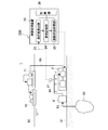
- the mining gas compression system 1 mainly compresses (pressurizes) the mining gas 54 contained in resources mined in a gas field or oil field existing underground or on the seabed, for example, an external processing facility. It is a system for pumping to a storage facility.
- the mining gas compression system 1 is applied to a plant for the ocean, and the mining gas 54 mined from the gas field 52 on the seabed 51 is targeted for compression, and the compressor 4 is installed on the seabed 51.
- the structure is illustrated.
- the mining gas compression system 1 may compress gas mined from other water bottoms such as a lake bottom and a river bottom, or the compressor 4 may be on the water such as on the sea or lake. Or it is good also as a structure installed on land. Or the mining gas compression system 1 is good also considering the gas mined from the underground as a compression object.
- the mining gas compression system 1 includes a gas-liquid separator 8, a compressor 4 connected to the gas-liquid separator 8, and a motor 5 for driving the compressor 4.
- the gas-liquid separator 8 is configured to separate a liquid component from a liquid-containing gas (mining gas) 53 mined from a gas field 52 existing on the seabed 51.
- a liquid-containing gas (mining gas) 53 mined from a gas field 52 existing on the seabed 51.
- the gas buried in the seabed 51 is often mined in a state containing a liquid component.
- the gas-liquid separator 8 separates the liquid component from the liquid-containing gas 53 and removes only the gas component.
- the liquid separation gas (mining gas) 54 that is included is sent to the compressor 4.
- the gas-liquid separator 8 may not be installed.
- the compressor 4 is connected to the output shaft 6 of the motor 5 and is configured to be driven by the motor 5 to increase the pressure of the fluid.
- the compressor 4 and the motor 5 may constitute the motor-integrated compressor 2 in which the compressor 4 and the motor 5 are accommodated inside the single casing 3.
- the compressor 4 and the motor 5 can be easily prevented from being corroded by seawater by forming the casing 3 in an airtight structure. Can protect.
- the compressor 4 and the motor 5 can be reduced in size, so that the space is limited. Space saving in the platform 11 can be achieved.
- the liquid-containing gas (mining gas) 53 mined from the gas field 52 on the seabed 51 is introduced into the gas-liquid separator 8, where the gas component and the liquid component are separated. Separated.
- the liquid separation gas (mining gas) 54 from which the liquid component has been separated by the gas-liquid separator 8 is introduced into the compressor 4 connected to the gas-liquid separator 8 and is pressurized by the compressor 4.
- the illustration is omitted.
- the compressed gas 55 discharged from the compressor 4 is sent to the outside of the mining gas compression system 1. For example, as illustrated, the compressed gas 55 is temporarily stored in a tank placed on the platform 11 floating on the sea surface 50 and then transported by the tanker 12.
- the specification of the compressor 4 is determined in consideration of the operating range (use conditions) of the compressor 4. Specifically, the specifications of the compressor 4 are determined according to the design life, assuming predetermined use conditions regarding the type of gas flowing into the compressor 4, the flow velocity, the compressor rotation speed, and the like.
- the operating range (use conditions) of the compressor 4 is uncertain, and the life of the compressor 4 is longer than the design life. May be shortened.
- the mining gas compression system 1 is applied to a marine plant as shown in FIG. 1, even if the compressor 4 breaks down, it takes time to prepare an alternative machine, during which time the plant operation is forced to stop.
- the life of the compressor 4 is evaluated by the state monitoring device 20A.
- the state monitoring apparatus 20 ⁇ / b> A performs a calculation for evaluating the life of the compressor 4 using the sensor 21 for detecting the state quantity of the mined gas 54 and the detection value of the sensor 21. And an arithmetic processing unit 22 configured.
- the sensor 21 is configured to detect a state quantity of the mined gas 54 flowing into the compressor 4. Specifically, the sensor 21 is provided in a gas line connecting the gas-liquid separator 8 and the compressor 4 and detects the state quantity of the mined gas 54 after the liquid component separation.
- the state quantity of the mining gas 54 may include at least one of the particle size of the foreign matter in the mining gas 54, the concentration of the foreign matter in the mining gas, or the hardness of the foreign matter.
- Arithmetic processing device 22 includes an erosion progress calculation unit 23, a life evaluation unit 24, and a storage unit 26.
- the arithmetic processing unit 22 includes, for example, a CPU (Central Processing Unit) (not shown), a RAM (Random Access Memory), a ROM (Read Only Memory), and / or other computer-readable recording media.
- a series of processing steps for realizing various functions to be described later are recorded in a recording medium or the like in the form of a program, and the CPU reads the program into a RAM or the like to execute information processing / arithmetic processing.
- the arithmetic processing unit 22 may be disposed in a remote place away from the mining gas compression system 1.
- the erosion progress calculation unit 23 is configured to calculate the erosion progress of the compressor 4 based on the state quantity of the mining gas 54.
- the state quantity of the mining gas 54 may include at least one of the particle size of the foreign matter in the mining gas 54, the concentration of the foreign matter in the mining gas, or the hardness of the foreign matter.
- the erosion progress calculation unit 23 may be configured to calculate the erosion progress based on the flow rate of the mining gas 54 in addition to the state quantity of the mining gas 54.
- the life evaluation unit 24 is configured to evaluate the life of the compressor 4 based on the erosion progress of the compressor 4.
- the storage unit 26 is configured to store various data such as the state quantity of the mining gas 54 detected by the sensor 21, for example.
- the erosion progress calculation unit 23 calculates the erosion progress speed W at each time based on the following equation (1), and the erosion is an accumulation of erosion up to an arbitrary time point based on the erosion progress speed W.
- a progress degree E is calculated.
- W K ⁇ U N ⁇ d M ⁇ H L (1)
- W is the erosion speed (the amount of erosion per unit time) of the compressor 4. That is, W indicates the erosion progress E per unit time.
- U is the flow velocity of the mining gas 54 flowing through the compressor 4
- d is the average particle size of the foreign matter contained in the mining gas 54
- H is the hardness of the foreign matter contained in the mining gas 54
- K, L , M, N are constants.
- K, L, M, and N are values determined by the system including the compressor 4.
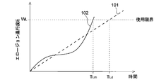
- FIG. 2 is a graph showing an example of the degree of progress of erosion, and is a diagram for explaining the design life and the actual life.
- a straight line 101 indicates the erosion progress E estimated under the conditions assumed at the time of design. That is, when it is assumed that the state quantity of the mining gas 54 is constant, the erosion progress speed W calculated by the above equation (1) is constant at any time, and therefore, the erosion progress E at each time.
- a value obtained by accumulating (erosion progress speed W) is a straight line 101.
- the curve 102 shows the erosion progress E calculated in the actual operation of the compressor 4. That is, in the actual operation of the compressor 4, since the state quantity changes with time, the erosion progress speed W calculated by the above equation (1) is different at each time. Therefore, the erosion progress degree E obtained by accumulating the erosion progress speeds W calculated for each time calculated by the above formula (1) is usually a curve 102 instead of a straight line.
- the life of the compressor 4 when the erosion progress E was defined as the time to reach W L corresponding to the use limitation of the compressor 4, the time linear 101 reaches the erosion progress W L T Ld becomes the design life, the time T Lm which the curve 102 reaches the erosion progress W L is the actual life.
- the actual life TLm is shorter than the design life TLd .
- the compressor 4 when the compressor 4 is rated-operated until the design life TLd , there is a possibility that a malfunction occurs. Therefore, before reaching the actual life T Lm, it is required to estimate the closer life by real life T Lm than the design life T Ld.
- the maintenance cost can be reduced by delaying the period of the periodic inspection.
- FIG. 3 is a graph showing an example of the degree of progress of erosion, and is a diagram for explaining the estimated life.
- the life evaluation unit 24 calculates the tangent line L of the curve 102 at the current time T 1, and when the slope of the tangent line L is larger than the straight line 101, it is used with the tangent line L.
- a time point corresponding to an intersection with the limit erosion progress level W L (that is, a time point when the tangent L reaches the erosion progress level W L ) is assumed to be an estimated life T L1 .
- the life evaluation of the compressor 4 since the life evaluation of the compressor 4 is performed in consideration of the erosion progress of the compressor 4 calculated based on the state quantity of the mining gas 54, the state quantity of the mining gas 54 changes. However, the life evaluation of the compressor 4 can be performed appropriately. In addition, if the lifetime evaluation result of the compressor 4 obtained in this way is used, the maintenance plan of the compressor 4 can be drawn up appropriately, the plant shutdown period can be shortened, and the profit of the whole plant can be improved. Further, if at least one of the particle size of the foreign matter in the mining gas 54, the concentration of the foreign matter in the mining gas or the hardness of the foreign matter is used as the state quantity of the mining gas 54, the foreign matter in the mining gas 54 is used.
- the life evaluation of the compressor 4 can be appropriately performed in consideration of the state quantity of the mining gas 54 such as the particle size, concentration, and hardness of the compressor 4. Furthermore, in the erosion progress calculation unit 23, not only the state quantity of the mining gas 54 but also the flow rate of the mining gas flowing into the compressor 4 can be considered, so that the life evaluation of the compressor 4 can be performed more appropriately. .
- the arithmetic processing unit 22 may further include an operation state switching unit 25. Based on the evaluation result by the life evaluation unit 24, the operation state switching unit 25 operates the compressor 4 between the rated operation state and the life extension operation state in which the erosion progress in the compressor 4 is slower than the rated operation state. Configured to switch between.
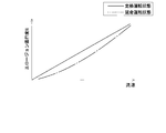
- FIG. 4 is a graph for explaining the rated operation state and the life extension operation state.
- the figure shows the relationship between the erosion progress E and the flow rate of the mining gas 54 in each operation state of the compressor 4.
- the solid line indicates the rated operation state, and the alternate long and short dash line indicates the life extension operation state.
- the erosion speed W of the compressor 4 is proportional to the Nth power (N> 1) of the flow rate of the mining gas 54 as shown in the above formula (1), the rotational speed of the compressor 4 (that is, the flow rate of the mining gas). ). Therefore, in the life extension operation state, by making the rotation speed of the compressor 4 smaller than the rated operation state, the erosion progress speed of the compressor 4 can be effectively suppressed, and the life of the compressor 4 can be effectively extended. it can. For example, when the rotation speed of the compressor 4 is halved, the erosion progress speed is less than 1 ⁇ 2, and a life-extending operation state with little wear can be realized. Or you may change the driving
- a filter for removing foreign substances is provided in the front stage of the compressor 4
- a filter having higher filtration performance than that used in the rated operation state is used in the life extension operation state.
- the particle size of the particles contained in the mining gas 54 is reduced.
- the operating state switching unit 25 is based on the current erosion progress, the deviation of the allowable erosion progress (usage limit erosion progress W L ), and the remaining time from the current time until the next periodic inspection.
- the operation condition in the life extension operation state may be determined. According to this configuration, the operating conditions in the life-extending operation state are determined in consideration of the remaining time until the next periodic inspection, so the life of the next compressor 4 is extended and the operation of the compressor 4 is stopped. The number of maintenance can be reduced while avoiding the problem. For example, the time obtained by dividing the deviation between the current erosion progress and the use limit erosion progress W L by the slope of the tangent L (see FIG.
- the operating condition may be changed based on the above formula (1).
- a virtual line indicating the erosion progress in the changed operating conditions calculated, this time corresponding to the intersection of the imaginary straight line and the working limit erosion progress W L may be changed to an operating condition so that the next time the periodic inspection timing.
- the current operating conditions are continued. May be used.
- the state monitoring method of the mining gas compression system 1 is based on the state quantity detection step (for example, S2) for detecting the state quantity of the mining gas 54 flowing into the compressor 4 and the state quantity of the mining gas 54.
- An erosion progress calculating step for example, S3 for calculating the erosion progress of the compressor 4
- a life evaluation step for example, S4 for evaluating the life of the compressor 4 based on the erosion progress of the compressor 4.
- the compressor 4 is operated in the rated operation state in step S1, and the state quantity of the mining gas 54 is detected in step S2.
- the state quantity includes at least one of the particle size of the foreign matter in the mining gas 54, the concentration of the foreign matter in the mining gas 54, or the hardness of the foreign matter.
- the erosion progress of the compressor 4 is calculated based on the state quantity of the mining gas 54.
- the erosion progress may be calculated based on the mining gas flow velocity in addition to the mining gas 54 state quantity.
- the erosion progress speed W may be calculated using the above equation (1)
- the erosion progress degree E may be calculated using the erosion progress speed W.
- the life of the compressor 4 is evaluated based on the erosion progress of the compressor 4.
- the life evaluation of the compressor 4 since the life evaluation of the compressor 4 is performed in consideration of the erosion progress of the compressor 4 calculated based on the state quantity of the mining gas 54, the state quantity of the mining gas 54 changes. However, the life evaluation of the compressor 4 can be performed appropriately. In addition, if the lifetime evaluation result of the compressor 4 obtained in this way is used, the maintenance plan of the compressor 4 can be drawn up appropriately, the plant shutdown period can be shortened, and the profit of the whole plant can be improved.
- the state monitoring method of the mining gas compression system 1 is based on the evaluation result in the life evaluation step, and between the rated operation state and the life extension operation state in which the erosion progress in the compressor is slower than the rated operation state.
- the operation state switching step (for example, S5, S6) for switching the operation state of 4 may be further provided.
- the life extension operation state is an operation state in which the rotation speed of the compressor 4 is smaller than the rated operation state. According to this method, since the operation state of the compressor 4 is switched between the rated operation state and the life extension operation state, the life of the compressor 4 is controlled based on the life evaluation result of the compressor 4. Can do.
- step S4 the calculated value of the erosion progress at the present time is compared with the allowable value of the erosion progress (the upper limit erosion progress W L for use), and these deviations and the next periodical from the present time are compared. Based on the remaining time until inspection, the life extension operation condition is determined.
- step S5 it is determined whether or not it can be used until the next periodic inspection. If it is determined that the compressor 4 can be used until the next periodic inspection, the rated operation state is continued until the next periodic inspection. If it is determined that the compressor 4 cannot be used, the operation state is switched in step S6, and the operation of the compressor 4 is continued in the life extension operation state in step S7.
- the operating condition in the life extension operation state is determined in consideration of the remaining time until the next periodic inspection, so that the life of the next compressor 4 is extended and the operation of the compressor 4 is stopped. The number of maintenance can be reduced while avoiding the problem.
- the life evaluation of the compressor 4 is performed in consideration of the erosion progress of the compressor 4 calculated based on the state quantity of the mining gas 54. Even if it changes, life evaluation of the compressor 4 can be performed appropriately.
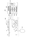
- FIG. 6 is a diagram illustrating a schematic configuration of a mining gas compression system 200 according to another embodiment.
- the mining gas compression system 200 includes a gas-liquid separator 8, a compressor 4 connected to the gas-liquid separator 8, and the compressor 4 in the same manner as the mining gas compression system 1 described above.
- the same reference numerals as those in FIG. 1 are assigned to components common to the respective parts of the mining gas compression system 1, and the description of the configuration is as described above, and thus the description thereof is omitted here.
- the specification of the compressor 4 is determined in consideration of the operating range (use conditions) of the compressor 4.
- the specifications of the compressor 4 are determined according to the design life, assuming predetermined use conditions regarding the type of gas flowing into the compressor 4, the flow velocity, the compressor rotation speed, and the like.
- the characteristics of the mining gas 54 can change, so the operating range (use conditions) of the compressor 4 is uncertain, and the life of the compressor 4 is longer than the design life. May be shortened. In particular, when applied to a marine plant as shown in FIG. 1, even if the compressor 4 breaks down, it takes time to prepare an alternative machine, during which time the plant is forced to stop operating.
- the state monitoring device 20B that can detect an abnormality of the mining gas compression system 200 with high accuracy is provided.
- the state monitoring apparatus 20B performs a calculation for detecting an abnormality of the compressor 4 using the sensor 221 for detecting the state quantity of the mining gas 54 and the detection value of the sensor 221. And an arithmetic processing unit 220 configured as described above.
- the sensor 221 is configured to detect a state quantity of the mined gas 54 flowing into the compressor 4. Specifically, the sensor 221 is provided in a gas line connecting the gas-liquid separator 8 and the compressor 4 and detects the state quantity of the mined gas 54 after the liquid component separation.
- the state quantity of the mining gas 54 may include at least one of the density, temperature, and pressure of the mining gas 54.
- the arithmetic processing device 220 includes a reference correlation acquisition unit 223, an output correction unit 224, an abnormality detection unit 225, and a storage unit 227.
- the arithmetic processing unit 220 includes, for example, a CPU (Central Processing Unit) (not shown), a RAM (Random Access Memory), a ROM (Read Only Memory), and / or other computer-readable recording media. A series of processing steps for realizing various functions to be described later are recorded in a recording medium or the like in the form of a program, and the CPU reads the program into a RAM or the like to execute information processing / arithmetic processing. Thus, the function of each unit of the arithmetic processing device 220 is realized.
- the processing unit 220 may be located at a remote location away from the mining gas compression system 200.
- the reference correlation acquisition unit 223 is configured to acquire a known reference correlation between the power supplied to the motor 5 related to the sample gas and the output of the compressor 4. As described above, the sample gas has a known reference state quantity.
- the known reference correlation may be acquired from the storage unit 227 or may be input from an input unit (not shown).
- the output correction unit 224 corrects the actual output of the compressor 4 based on the state quantity of the mining gas 54 detected by the sensor 221 and corresponds to the power supplied to the motor 5 when the mining gas 54 has a reference state quantity.
- the output correction value of the compressor 4 is configured to be calculated.
- the abnormality detection unit 225 detects an abnormality in the mining gas compression system 200 based on the comparison result between the relationship between the power supplied to the motor 5 and the output correction value and the reference correlation.
- the storage unit 227 stores, for example, a known reference correlation between the power supplied to the motor 5 and the output of the compressor 4 regarding the sample gas.
- the storage unit 227 stores a known reference correlation acquired in advance. This known reference correlation may be acquired, for example, by an experiment using a sample gas, may be acquired by simulation, or may be acquired from empirical past data.
- the known reference correlation acquired in this way may be stored in the storage unit 227 via a communication line or a storage medium, or may be stored in the storage unit 227 by an input from the input unit of the arithmetic processing device 22. .
- the storage unit 227 stores at least one reference correlation. As will be described later, when abnormality detection is performed, the output of the compressor 4 is corrected based on the state quantity corresponding to the reference correlation, and then the reference correlation and the output correction value of the compressor 4 are compared. In principle, the storage unit 227 only needs to store one reference correlation. However, the storage unit 227 may store a known reference correlation between the power supplied to the motor 5 and the output of the compressor 4 for each of a plurality of types of sample gases having different state quantities.
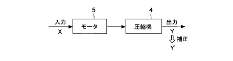
- FIG. 7 is a diagram for explaining input / output of the motor 5 and the compressor 4 according to an embodiment.
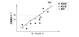
- FIG. 8 is a graph showing an example of actual measurement values and correction values for the reference correlation 300.
- the motor 5 drives the compressor 4 with the output Y when electric power (motor input X) is supplied.
- the known reference correlation between the power supplied to the motor 5 (motor input X) and the output Y of the compressor 4 with respect to the sample gas having a known reference state quantity is a straight line 300. expressed.
- the measured value and the corrected value of the output of the compressor 4 are also plotted separately from the known reference correlation 300.
- Measured value of the output of the compressor 4 is an actual output Y 1 of the compressor 4 to the actual power supplied to the motor 5 (motor input X).
- the output Y of the compressor 4 can be obtained by the following equation (1).
- Y is the output (kW) of the compressor 4
- Q is the gas volume before compression (m 3 / s)
- P 1 is the pressure before compression (N / m 2 )
- P 2 is the pressure after compression (N N / m 2 )
- K and m are constants.
- the output in the correction unit 224 calculates the actual output Y 1 output correction value Y obtained by correcting the 'compressor 4 based on the state quantity of mining gas 54.
- the output correction value Y ′ of the compressor 4 is obtained by the following equation (2) when the state quantity is density, for example.
- Y ′ is the output correction value (kW) of the compressor 4
- Y 1 is the actual output (kW) of the compressor 4
- ⁇ 0 is the density of the sample gas
- ⁇ is the mined gas 54 detected by the sensor 221. Density.
- the above formula (2) describes the influence of the density as the state quantity on the output of the compressor 4. In other embodiments, for other state quantities that may change during operation of the mining gas compression system 200 (eg, temperature, pressure, etc. of the mining gas 54), the effect of the state quantities on the output of the compressor 4 is described.
- the output correction value Y ′ of the compressor 4 is calculated using the mathematical formula or table.
- the correction value plotted in the figure based on the output correction value Y ′ of the compressor 4 and the input X of the motor 5 obtained in this way is the mining gas if there is no abnormality in the motor 5 or the compressor 4.
- the configuration generally follows the known reference correlation 300.
- the output correction value Y ′ of the compressor 4 that is greatly deviated from the known reference correlation 300 can be determined to be abnormal. Therefore, in some embodiments, the abnormality detection unit 225 compares the relationship between the power supplied to the motor 5 (motor input X) and the output correction value Y ′ of the compressor 4 and the reference correlation 300. Based on this, an abnormality of the mining gas compression system 200 is detected.
- the state monitor 20B having the above structure, mining by correcting the actual output Y 1 of the compressor 4 based on a detection result of the state of the gas 54, known mining gas 54 is the reference state amount (the sample gas).
- the output correction value Y ′ of the compressor 4 corresponding to the motor supply power (motor input X) is calculated. Since the output correction value Y ′ of the compressor 4 obtained in this way is based on the same state quantity (reference state quantity) as the sample gas, the motor supply is not affected by the fluctuation of the state quantity of the mining gas 54.
- the relationship between the power and the output correction value Y ′ can be appropriately compared with the reference correlation 300. Therefore, even if the operating range of the compressor 4 is uncertain due to fluctuations in the state quantity of the mining gas 54, it is possible to detect an abnormality as a precursor to the failure of the mining gas compression system 200.
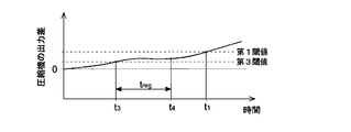
- Figure 9 is a graph showing an example of a time series change of the difference D between the reference output Y 0 and the output correction value Y '.
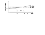
- Figure 10 is a graph showing an example of a time-series change in the rate of deviation output correction value Y 'with respect to the reference output Y 0.
- the reference numerals shown in FIGS. 6 and 7 are used as appropriate. Further, in the graph shown in FIGS.
- a reference output Y 0 output correction value Y 'time series change of the difference between, or the output correction value Y with respect to the reference output Y 0' time series change in the rate of deviation is Each of the values calculated intermittently is schematically shown by a curve.
- the abnormality detection unit 225 includes the reference output Y 0 of the compressor 4 corresponding to the power (motor input X) supplied to the motor 5 in the reference correlation 300 (see FIG. 3). Then, it is configured to determine that an abnormality has occurred in the mining gas compression system 200 at time t 1 when the difference D from the output correction value Y ′ calculated by the output correction unit 224 exceeds the first threshold value. For example, when the absolute value of the difference D between the reference output Y 0 of the compressor 4 and the output correction value Y 'exceeds the first threshold value, it may be determined that an abnormality has occurred in the mining gas compression system 200.
- the absolute amount may be provided a positive first threshold value and a negative first threshold value is the same, the difference D of the reference output Y 0 of the compressor 4 and the output correction value Y 'is a positive first threshold value when exceeded, or when the difference D between the reference output Y 0 of the compressor 4 and the output correction value Y 'is below a negative first threshold value, be judged that an abnormality has occurred in the mining gas compression system 200 Good.
- the abnormality detection unit 225 has the reference output Y 0 of the compressor 4 corresponding to the power (motor input X) supplied to the motor 5 in the reference correlation 300 (see FIG. 8). for, at time t 2 when the rate of deviation calculated by the output correction unit 224 outputs the correction value Y 'exceeds the second threshold value, configured to determine that an abnormality has occurred in the mining gas compression system 200.
- the deviation rate of the output correction value Y ′ may be a value obtained by dividing the difference D between the reference output Y 0 and the output correction value Y ′ by the reference output Y 0 .
- the second threshold when the absolute value of the deviation rate from the output correction value Y ′ with respect to the reference output Y 0 of the compressor 4 exceeds the second threshold, it may be determined that an abnormality has occurred in the mining gas compression system 200.
- a positive second threshold value and a negative second threshold value having the same absolute amount are provided, and a second threshold value having a positive deviation rate from the output correction value Y ′ with respect to the reference output Y 0 of the compressor 4 is set.
- a negative second threshold value when exceeded, or when the output correction value Y 'with the deviation rate with respect to a reference output Y 0 of the compressor 4 is lower than a negative second threshold value, be determined that abnormality has occurred in the mining gas compression system 200 Good.
- reference correlation 300 reference output Y 0 of the compressor 4 corresponding to the supply power (motor input X) to the motor 5 which is determined based on (see FIG. 8), which is calculated by the output correction unit 224 outputs
- the deviation rate of the correction value Y ′ By comparing the deviation rate of the correction value Y ′ with the second threshold value, it is possible to determine whether there is an abnormality in the mining gas compression system 200 even if the operation range of the compressor 4 is uncertain due to fluctuations in the state quantity of the mining gas 54. It can be determined with high accuracy.
- the abnormality detection unit 225 includes the compressor 4 corresponding to the power (motor input X) supplied to the motor 5 in the reference correlation 300 (see FIG. 8).
- a reference output Y 0 the output correction unit 224 outputs the correction value Y calculated by 'the difference between or reference output Y 0 output correction value Y for,' the deviation rate period that exceeds a third threshold value specified time t of It is configured to determine that an abnormality has occurred in the mining gas compression system 200 when continuing for more than reg .
- the abnormality detecting unit 225, the reference output Y 0 of the compressor 4 and the output correction value Y 'the difference between, or the output correction value Y with respect to the reference output Y 0' rate of deviation exceeds a third threshold value counting the elapsed time from t 3, it determines that an abnormality has occurred at time t 4 when the elapsed time reaches the specified time t reg.
- the occurrence of abnormality may be determined by the above-described method using two types of thresholds such as the first threshold value and the third threshold value shown in FIG. 9 or the second threshold value and the third threshold value shown in FIG. .
- the third threshold value may be a value smaller than the first threshold value or the second threshold value.
- the reference output Y 0 of the compressor 4 and the output correction value Y 'the difference between, or the reference output Y 0 to the output correction value Y' period deviation rate exceeds a third threshold value of the specified time t reg Based on whether or not the above is true, whether or not the mining gas compression system 200 is abnormal can be determined with high accuracy even if the operating range of the compressor 4 is uncertain due to fluctuations in the state quantity of the mining gas 54. it can.
- the abnormality detection unit 225 also outputs the reference output Y 0 of the compressor 4 corresponding to the power supplied to the motor 5 (motor input X) in the reference correlation 300 and the output correction value Y ′ calculated by the output correction unit 224. the difference between, or when the rate of increase of the deviation rate of the output correction value Y 'with respect to the reference output Y 0 exceeds the fourth threshold value (not shown), to determine that an abnormality has occurred in the mining gas compression system 200 It may be configured. That is, the abnormality detecting unit 225, the reference output Y 0 of the compressor 4 and the output correction value Y 'difference between the value obtained by differentiating in (see FIG.
- the reference output Y 0 of the compressor 4 and the output correction value Y 'the difference between, or the output correction value Y with respect to the reference output Y 0' the rate of increase in the rate of deviation is compared with a fourth threshold value Even if the operating range of the compressor 4 is uncertain due to fluctuations in the state quantity of the mining gas 54, the presence or absence of an abnormality in the mining gas compression system 200 can be determined with high accuracy.
- the above-described state monitoring device 20B may further include the following configuration.
- the arithmetic processing device 22 of the state monitoring device 20B further includes an abnormal point specifying unit 26 (see FIG. 6).
- Abnormal point identifying unit 26 the abnormality when the detection unit 225 of the drilling gas compression system 200 failure is detected, the actual output Z 1 and design output value of the motor 5 corresponding to the power supplied to the motor 5 (motor input X) Based on the comparison result of Z 0 , it is configured to specify whether the abnormality occurrence location is the compressor 4 or the motor 5.
- FIG. 11 is a diagram for explaining input / output of the motor 5 and the compressor 4 according to another embodiment.
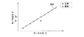
- FIG. 12 is a graph showing the relationship between the motor input X and the motor output Z.
- the motor 5 is driven by an output (motor output) Z by being supplied with electric power (motor input X).
- the motor output Z is input to the compressor 4 as rotational energy having a torque T and a rotational speed N, and the compressor 4 is driven with an output Y.
- the motor output Z is calculated by the following equation (3), for example.
- Z is the motor output (kW)
- T is the torque [kg ⁇ m (N / m / 9.8)]
- N is the rotational speed (min ⁇ 1 ).
- the design output Z 0 of the motor 5 with respect to the power supplied to the motor 5 (motor input X) is indicated by a straight line 302.
- the abnormal part is determined based on the comparison result between the actual output Z 1 and the design output value Z 0 of the motor 5 corresponding to the power supplied to the motor 5 (motor input). 5 is specified. For example, when the difference between the motor actual output Z 1 corresponding to the motor supply power and the design output value Z 0 is within the allowable range, the abnormality occurrence point is considered to be the compressor 4 instead of the motor 5.
- the abnormality occurrence location is considered to be the motor 5 instead of the compressor 4.
- the motor actual output Z 1 and the design output value Z 0 corresponding to the motor supply electric power it is possible to identify the abnormal location.
- the abnormal location specifying unit 26 may use, as the actual output Z 1 of the motor 5, an output correction value Z ′ obtained by correcting the actual output Z 1 with the state quantity. In that case, the abnormal point specifying unit 26 determines whether the abnormal point is the compressor 4 or the motor based on the comparison result between the output correction value Z ′ obtained by correcting the actual output Z 1 by the state quantity and the design output value Z 0. 5 is specified.
- the output correction value Z ′ of the motor 5 is calculated by the following equation (4).
- Z ′ is the motor output correction value (kW)
- Z 1 is the actual output (kW) of the motor
- ⁇ 0 is the density of the sample gas
- ⁇ is the density of the mining gas 54 detected by the sensor 221.
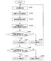
- step S101 when the motor 5 and the compressor 4 are operating in the rated operation state in step S101, the state quantity of the mining gas 54 flowing into the compressor 4 in step S102 (state quantity detection step).
- the sensor 221 detects (for example, the density, temperature, pressure, etc. of the mined gas 54).
- step S103 reference correlation acquisition step
- a known reference correlation 300 between the power supplied to the motor 5 (motor input X) and the reference output Y of the compressor 4 with respect to the sample gas having a known reference state quantity. Keep getting.
- step S103 for example, the known reference correlation 300 may be read from the storage unit 227.
- step S104 output correction step
- the actual output Y 1 of the compressor 4 is corrected based on the state quantity of mining gas 54 is detected by the sensor 221, mining gas 54 has a reference state amount
- the output correction value Y ′ of the compressor 4 corresponding to the power supplied to the motor 5 (motor input X) is calculated.
- the actual output Y 1 of the compressor 4 obtained by the above equation (1) is corrected by the above equation (2), and the output correction value Y ′ of the compressor 4 is calculated.
- steps S105 to S107 abnormality detection step
- the abnormality of the mining gas compression system 200 is detected.
- step S105 the determination in step S105, the reference output Y 0 of the compressor 4 corresponding to the power supplied to the motor 5 at a reference correlation 300, whether or not the difference D between the output correction value Y 'exceeds the first threshold value and the difference D of the reference output Y 0 of the compressor 4 and the output correction value Y 'is in the case does not exceed the first threshold value it is determined that no abnormality mining gas compression system 200 in step S106, to step S101 Return to continue rated operation.
- step S107 determines the difference D of the reference output Y 0 of the compressor 4 and the output correction value Y 'is a case of exceeding the first threshold value, in step S107, a malfunction occurs in the mining gas compression system 200 and.
- steps S108 in through step S110 abnormal point identifying step
- the actual output Z 1 and design of the motor 5 corresponding to the fourth power supply to the motor (motor input X) Based on the comparison result of the output value Z 0 , it is specified which of the compressor 4 and the motor 5 is where the abnormality has occurred.
- step S108 the difference between the actual output Z 1 and the design output value Z 0 of the motor 5 as compared to the fifth threshold value, the difference is a fifth threshold value and the actual output Z 1 and the design output value Z 0 of the motor 5 If it is smaller, it is determined in step S109 that the compressor 4 is abnormal. On the other hand, it determines the difference between the actual output Z 1 and the design output value Z 0 of the motor 5 is in the case where more than a fifth threshold value, that there is an abnormality in the motor 5 in step S110.
- the abnormal point identifying step may be compared with the actual rate of deviation and a sixth threshold value of the design output value Z 0 for the output Z 1 of the motor 5.
- an abnormality as a precursor of a failure of the mining gas compression system 200 is detected. Can be detected.
- the mining gas compression system 200 shown in FIG. 6 is provided with the state monitoring apparatus 20B mentioned above. That is, the mining gas compression system 200 includes the compressor 4 for boosting the mining gas 54, the motor 5 for driving the compressor 4, and the state monitoring device 20B described above. Thereby, even if the operating range of the compressor 4 is uncertain due to fluctuations in the state quantity of the mining gas 54, it is possible to detect an abnormality as a precursor to the failure of the mining gas compression system 200. Therefore, it is possible to avoid a long-term shutdown due to a sudden failure of the mining gas compression system 200, and improve the profitability of the gas mining company.
- the present invention is not limited to the above-described embodiments, and includes forms obtained by modifying the above-described embodiments and forms obtained by appropriately combining these forms.
- expressions representing shapes such as quadrangular shapes and cylindrical shapes represent not only geometrically strict shapes such as quadrangular shapes and cylindrical shapes, but also irregularities and chamfers as long as the same effects can be obtained.
- a shape including a part or the like is also expressed.
- the expression “comprising”, “including”, or “having” one constituent element is not an exclusive expression that excludes the presence of the other constituent elements.
Landscapes
- Engineering & Computer Science (AREA)
- General Engineering & Computer Science (AREA)
- Mechanical Engineering (AREA)
- Physics & Mathematics (AREA)
- General Physics & Mathematics (AREA)
- Computer Hardware Design (AREA)
- Theoretical Computer Science (AREA)
- Automation & Control Theory (AREA)
- Chemical & Material Sciences (AREA)
- Analytical Chemistry (AREA)
- Plasma & Fusion (AREA)
- Quality & Reliability (AREA)
- Control Of Positive-Displacement Pumps (AREA)
- Control Of Positive-Displacement Air Blowers (AREA)
Abstract
採掘ガスを昇圧する圧縮機を有する採掘ガス圧縮システムの状態監視装置は、前記圧縮機に流入する前記採掘ガスの状態量を検出するためのセンサと、前記採掘ガスの前記状態量に基づいて前記圧縮機のエロージョン進行度を算出するためのエロージョン進行度算出部と、前記圧縮機の前記エロージョン進行度に基づいて、前記圧縮機の寿命を評価するための寿命評価部と、備える。
Description
本開示は、採掘ガス圧縮システムの状態監視装置及び状態監視方法、並びに、採掘ガス圧縮システムに関する。
石油や天然ガス等の海底資源の採掘において、採掘された資源に含まれる気体成分を昇圧させて陸上設備や海上の浮体式設備に圧送するために圧縮機が用いられる。
例えば、非特許文献1には、海底のガス井から気液混合状態で採掘される天然ガスを海底にて気液分離して気体成分と液体成分に分離した後、気体成分を圧縮機で昇圧させて、陸上設備に送ることが記載されている。
例えば、非特許文献1には、海底のガス井から気液混合状態で採掘される天然ガスを海底にて気液分離して気体成分と液体成分に分離した後、気体成分を圧縮機で昇圧させて、陸上設備に送ることが記載されている。
Turbomachinery International, September/October 2014, p.18-24
ところで、圧縮機の仕様は、圧縮機の運転範囲(使用条件)を考慮して決定されている。具体的には、圧縮機に流入するガスの種類、流速、圧縮機回転数等に関する所定の使用条件を想定し、設計寿命に応じて圧縮機の仕様が決定される。
しかしながら、採掘ガス圧縮システムの場合、採掘ガスの特性が変化し得るため、圧縮機の運転範囲が不確定である。例えば、採掘ガス中の異物の粒径および硬度が、運転時間の経過とともに変化することが考えられる。このため、採掘ガス圧縮システムの場合、圧縮機の寿命が設計寿命よりも短くなってしまう可能性がある。
採掘ガス圧縮システムは、海洋向けプラントに適用されることが多い。海洋向けプラントでは圧縮機が故障しても、代替機の準備に時間を要し、その間プラントの運転停止を余儀なくされる。特に、採掘現場が海底に存在する場合、圧縮機の取外し、据付け作業に多大な時間を要するため、プラントの運転停止期間がさらに延びてしまう。
この点、非特許文献1には、採掘ガス圧縮システムにおける圧縮機の寿命評価手法について記載がない。
本発明の少なくとも幾つかの実施形態の目的は、採掘ガスの状態量の変動を考慮して圧縮機の状態を監視することができる採掘ガス圧縮システムの状態監視装置及び状態監視方法、並びに、採掘ガス圧縮システムを提供することである。
(1)本発明の少なくとも幾つかの実施形態に係る採掘ガス圧縮システムの状態監視装置は、
採掘ガスを昇圧する圧縮機を有する採掘ガス圧縮システムの状態監視装置であって、
前記圧縮機に流入する前記採掘ガスの状態量を検出するためのセンサと、
前記採掘ガスの前記状態量に基づいて前記圧縮機のエロージョン進行度を算出するためのエロージョン進行度算出部と、
前記圧縮機の前記エロージョン進行度に基づいて、前記圧縮機の寿命を評価するための寿命評価部と、
を備える。
採掘ガスを昇圧する圧縮機を有する採掘ガス圧縮システムの状態監視装置であって、
前記圧縮機に流入する前記採掘ガスの状態量を検出するためのセンサと、
前記採掘ガスの前記状態量に基づいて前記圧縮機のエロージョン進行度を算出するためのエロージョン進行度算出部と、
前記圧縮機の前記エロージョン進行度に基づいて、前記圧縮機の寿命を評価するための寿命評価部と、
を備える。
上記(1)の構成によれば、採掘ガスの状態量に基づいて算出した圧縮機のエロージョン進行度を考慮して圧縮機の寿命評価を行うようにしたので、採掘ガスの状態量が変化しても、採掘ガス圧縮システムの状態監視の一環として圧縮機の寿命評価を適切に行うことができる。
なお、こうして得られた圧縮機の寿命評価結果を用いれば、圧縮機のメンテナンス計画を適切に立案でき、プラントの運転停止期間を短縮してプラント全体としての収益を改善することができる。
なお、こうして得られた圧縮機の寿命評価結果を用いれば、圧縮機のメンテナンス計画を適切に立案でき、プラントの運転停止期間を短縮してプラント全体としての収益を改善することができる。
(2)幾つかの実施形態では、上記(1)の構成において、
前記状態量は、前記採掘ガス中の異物の粒径、該異物の前記採掘ガス中における濃度又は該異物の硬度の少なくとも一つを含む。
前記状態量は、前記採掘ガス中の異物の粒径、該異物の前記採掘ガス中における濃度又は該異物の硬度の少なくとも一つを含む。
上記(2)の構成によれば、採掘ガス中の異物の粒径、濃度、硬度等の採掘ガスの状態量を考慮して、圧縮機の寿命評価を適切に行うことができる。
(3)幾つかの実施形態では、上記(1)又は(2)の構成において、
前記エロージョン進行度算出部は、前記採掘ガスの前記状態量に加えて、前記採掘ガスの流速に基づいて、前記エロージョン進行度を算出するように構成される。
前記エロージョン進行度算出部は、前記採掘ガスの前記状態量に加えて、前記採掘ガスの流速に基づいて、前記エロージョン進行度を算出するように構成される。
上記(3)の構成によれば、採掘ガスの状態量だけでなく、圧縮機に流入する採掘ガスの流速を考慮することで、圧縮機の寿命評価をより適切に行うことができる。
(4)幾つかの実施形態では、上記(1)乃至(3)の何れかの構成において、
採掘ガス圧縮システムの状態監視装置が、
前記寿命評価部による評価結果に基づいて、定格運転状態と、該定格運転状態よりも前記圧縮機におけるエロージョン進行が遅い延命運転状態との間で前記圧縮機の運転状態を切り替えるように構成された運転状態切替部をさらに備える。
採掘ガス圧縮システムの状態監視装置が、
前記寿命評価部による評価結果に基づいて、定格運転状態と、該定格運転状態よりも前記圧縮機におけるエロージョン進行が遅い延命運転状態との間で前記圧縮機の運転状態を切り替えるように構成された運転状態切替部をさらに備える。
上記(4)の構成によれば、定格運転状態と延命運転状態との間で圧縮機の運転状態を切り替えるようにしたので、圧縮機の寿命評価結果に基づいて、圧縮機の寿命を制御することができる。
(5)幾つかの実施形態では、上記(4)の構成において、
前記延命運転状態は、前記圧縮機の回転数が前記定格運転状態よりも小さい。
前記延命運転状態は、前記圧縮機の回転数が前記定格運転状態よりも小さい。
圧縮機のエロージョン進行速度は、採掘ガスの流速のN乗(N>1)に比例するから、圧縮機の回転数(即ち採掘ガスの流速)に対する感度が大きい。
この点、上記(4)の構成によれば、延命運転状態において、圧縮機の回転数を定格運転状態よりも小さくすることで、圧縮機のエロージョン進行速度を効果的に抑制し、圧縮機の寿命を効果的に延ばすことができる。
この点、上記(4)の構成によれば、延命運転状態において、圧縮機の回転数を定格運転状態よりも小さくすることで、圧縮機のエロージョン進行速度を効果的に抑制し、圧縮機の寿命を効果的に延ばすことができる。
(6)幾つかの実施形態では、上記(4)又は(5)の構成において、
前記運転状態切替部は、現時点での前記エロージョン進行度および前記エロージョン進行度の許容値の偏差と、現時点から次回の定期点検までの残時間と、に基づいて、前記延命運転状態における運転条件を決定するように構成される。
前記運転状態切替部は、現時点での前記エロージョン進行度および前記エロージョン進行度の許容値の偏差と、現時点から次回の定期点検までの残時間と、に基づいて、前記延命運転状態における運転条件を決定するように構成される。
上記(6)の構成によれば、次回の定期点検までの残時間を考慮して、延命運転状態における運転条件を決定するようにしたので、次回の圧縮機の寿命を延ばして、圧縮機の運転停止を回避しながら、メンテナンス回数を減らすことができる。
(7)幾つかの実施形態では、
前記採掘ガス圧縮システムは、前記圧縮機を駆動するためのモータをさらに有し、
採掘ガス圧縮システムの状態監視装置が、
既知の基準状態量を有するサンプルガスに関する前記モータへの供給電力と前記圧縮機の出力との既知の基準相関関係を取得するための基準相関関係取得部と、
前記センサによって検出された前記採掘ガスの前記状態量に基づいて前記圧縮機の実際出力を補正し、前記採掘ガスが前記基準状態量を有する場合における前記モータへの供給電力に対応する前記圧縮機の出力補正値を算出するための出力補正部と、
前記モータへの供給電力と前記出力補正値との関係と前記基準相関関係との比較結果に基づいて、前記採掘ガス圧縮システムの異常を検出するための異常検出部と、
をさらに備える。
前記採掘ガス圧縮システムは、前記圧縮機を駆動するためのモータをさらに有し、
採掘ガス圧縮システムの状態監視装置が、
既知の基準状態量を有するサンプルガスに関する前記モータへの供給電力と前記圧縮機の出力との既知の基準相関関係を取得するための基準相関関係取得部と、
前記センサによって検出された前記採掘ガスの前記状態量に基づいて前記圧縮機の実際出力を補正し、前記採掘ガスが前記基準状態量を有する場合における前記モータへの供給電力に対応する前記圧縮機の出力補正値を算出するための出力補正部と、
前記モータへの供給電力と前記出力補正値との関係と前記基準相関関係との比較結果に基づいて、前記採掘ガス圧縮システムの異常を検出するための異常検出部と、
をさらに備える。
(7’)本発明の少なくとも幾つかの実施形態に係る採掘ガス圧縮システムの状態監視装置は、
上記(1)で述べた構成の有無にかかわらず、
採掘ガスを昇圧する圧縮機と、該圧縮機を駆動するモータと、を有する採掘ガス圧縮システムの状態監視装置であって、
前記圧縮機に流入する前記採掘ガスの状態量を検出するためのセンサと、
既知の基準状態量を有するサンプルガスに関する前記モータへの供給電力(モータ入力)と前記圧縮機の出力との既知の基準相関関係を取得するための基準相関関係取得部と、
前記センサによって検出された前記採掘ガスの前記状態量に基づいて前記圧縮機の実際出力を補正し、前記採掘ガスが前記基準状態量を有する場合における前記モータへの供給電力に対応する前記圧縮機の出力補正値を算出するための出力補正部と、
前記モータへの供給電力と前記出力補正値との関係と前記基準相関関係との比較結果に基づいて、前記採掘ガス圧縮システムの異常を検出するための異常検出部と、
を備える。
上記(1)で述べた構成の有無にかかわらず、
採掘ガスを昇圧する圧縮機と、該圧縮機を駆動するモータと、を有する採掘ガス圧縮システムの状態監視装置であって、
前記圧縮機に流入する前記採掘ガスの状態量を検出するためのセンサと、
既知の基準状態量を有するサンプルガスに関する前記モータへの供給電力(モータ入力)と前記圧縮機の出力との既知の基準相関関係を取得するための基準相関関係取得部と、
前記センサによって検出された前記採掘ガスの前記状態量に基づいて前記圧縮機の実際出力を補正し、前記採掘ガスが前記基準状態量を有する場合における前記モータへの供給電力に対応する前記圧縮機の出力補正値を算出するための出力補正部と、
前記モータへの供給電力と前記出力補正値との関係と前記基準相関関係との比較結果に基づいて、前記採掘ガス圧縮システムの異常を検出するための異常検出部と、
を備える。
上記(7)又は(7’)の構成では、採掘ガスの状態量の検出結果に基づいて圧縮機の実際出力を補正することで、採掘ガスが基準状態量(サンプルガスの既知の状態量)を有する場合におけるモータ供給電力に対応する圧縮機の出力補正値を算出するようになっている。こうして得られた圧縮機の出力補正値は、サンプルガスと同一の状態量(基準状態量)を前提としているため、採掘ガスの状態量の変動の影響を受けずに、モータ供給電力と出力補正値との関係を基準相関関係と適切に比較することができる。よって、採掘ガスの状態量の変動によって圧縮機の運転範囲が不確定であっても、採掘ガス圧縮システムの故障の前兆としての異常を検知することができる。
(8)幾つかの実施形態では、上記(7)又は(7’)の構成において、
採掘ガス圧縮システムの状態監視装置が、
前記異常検出部により前記採掘ガス圧縮システムの異常が検出されたとき、前記モータへの供給電力に対応する前記モータの実際出力および設計出力値の比較結果に基づいて、前記異常の発生箇所が前記圧縮機又は前記モータの何れであるかを特定するように構成された異常箇所特定部をさらに備える。
採掘ガス圧縮システムの状態監視装置が、
前記異常検出部により前記採掘ガス圧縮システムの異常が検出されたとき、前記モータへの供給電力に対応する前記モータの実際出力および設計出力値の比較結果に基づいて、前記異常の発生箇所が前記圧縮機又は前記モータの何れであるかを特定するように構成された異常箇所特定部をさらに備える。
上記(7)又は(7’)の構成において、異常検出部により採掘ガス圧縮システムの異常が検出されると、異常発生箇所として主に考えられるのはモータ又は圧縮機の何れかである。
そこで、上記(8)の構成では、モータ供給電力に対応するモータ実際出力および設計出力値の比較結果に基づいて、異常の発生箇所が圧縮機又はモータの何れであるかを特定するようになっている。
例えば、モータ供給電力に対応するモータ実際出力および設計出力値の差が許容範囲内である場合、異常発生箇所はモータではなく圧縮機であると考えられる。一方、モータ供給電力に対応するモータ実際出力および設計出力値の差が許容範囲を超えている場合、異常発生箇所は圧縮機ではなくモータであると考えられる。こうして、モータ供給電力に対応するモータ実際出力および設計出力値の比較結果に基づき、異常発生箇所を特定することができる。
そこで、上記(8)の構成では、モータ供給電力に対応するモータ実際出力および設計出力値の比較結果に基づいて、異常の発生箇所が圧縮機又はモータの何れであるかを特定するようになっている。
例えば、モータ供給電力に対応するモータ実際出力および設計出力値の差が許容範囲内である場合、異常発生箇所はモータではなく圧縮機であると考えられる。一方、モータ供給電力に対応するモータ実際出力および設計出力値の差が許容範囲を超えている場合、異常発生箇所は圧縮機ではなくモータであると考えられる。こうして、モータ供給電力に対応するモータ実際出力および設計出力値の比較結果に基づき、異常発生箇所を特定することができる。
(9)幾つかの実施形態では、上記(7)、(7’)又は(8)の構成において、
前記異常検出部は、前記基準相関関係における前記モータへの供給電力に対応した前記圧縮機の基準出力と、前記出力補正部によって算出された前記出力補正値との差が第1閾値を超えたとき、前記採掘ガス圧縮システムに異常が発生したと判定するように構成される。
前記異常検出部は、前記基準相関関係における前記モータへの供給電力に対応した前記圧縮機の基準出力と、前記出力補正部によって算出された前記出力補正値との差が第1閾値を超えたとき、前記採掘ガス圧縮システムに異常が発生したと判定するように構成される。
上記(9)の構成によれば、基準相関関係に基づいて定まるモータ供給電力に対応した圧縮機の基準出力と、出力補正部によって算出された出力補正値との差を第1閾値と比較することで、採掘ガスの状態量の変動によって圧縮機の運転範囲が不確定であっても、採掘ガス圧縮システムの異常の有無を高精度に判定することができる。
(10)幾つかの実施形態では、上記(7)、(7’)又は(8)の構成において、
前記異常検出部は、前記基準相関関係における前記モータへの供給電力に対応した前記圧縮機の基準出力に対する、前記出力補正部によって算出された前記出力補正値の乖離率が第2閾値を超えたとき、前記採掘ガス圧縮システムに異常が発生したと判定するように構成される。
前記異常検出部は、前記基準相関関係における前記モータへの供給電力に対応した前記圧縮機の基準出力に対する、前記出力補正部によって算出された前記出力補正値の乖離率が第2閾値を超えたとき、前記採掘ガス圧縮システムに異常が発生したと判定するように構成される。
上記(10)の構成によれば、基準相関関係に基づいて定まるモータ供給電力に対応した圧縮機の基準出力に対する、出力補正部によって算出された出力補正値の乖離率を第2閾値と比較することで、採掘ガスの状態量の変動によって圧縮機の運転範囲が不確定であっても、採掘ガス圧縮システムの異常の有無を高精度に判定することができる。
(11)幾つかの実施形態では、上記(7)、(7’)又は(8)の構成において、
前記異常検出部は、前記基準相関関係における前記モータへの供給電力に対応した前記圧縮機の基準出力と、前記出力補正部によって算出された前記出力補正値との差、または、前記基準出力に対する前記出力補正値の乖離率が第3閾値を超える期間が規定時間以上継続したとき、前記採掘ガス圧縮システムに異常が発生したと判定するように構成される。
前記異常検出部は、前記基準相関関係における前記モータへの供給電力に対応した前記圧縮機の基準出力と、前記出力補正部によって算出された前記出力補正値との差、または、前記基準出力に対する前記出力補正値の乖離率が第3閾値を超える期間が規定時間以上継続したとき、前記採掘ガス圧縮システムに異常が発生したと判定するように構成される。
上記(11)の構成によれば、圧縮機の基準出力と出力補正値との差、または、基準出力に対する出力補正値の乖離率が第3閾値を超えた期間が規定時間以上であるか否かに基づいて、採掘ガスの状態量の変動によって圧縮機の運転範囲が不確定であっても、採掘ガス圧縮システムの異常の有無を高精度に判定することができる。
(12)幾つかの実施形態では、上記(7)、(7’)又は(8)の構成において、
前記異常検出部は、前記基準相関関係における前記モータへの供給電力に対応した前記圧縮機の基準出力と、前記出力補正部によって算出された前記出力補正値との差、または、前記基準出力に対する前記出力補正値の乖離率の増大速度が第4閾値を超えたとき、前記採掘ガス圧縮システムに異常が発生したと判定するように構成される。
前記異常検出部は、前記基準相関関係における前記モータへの供給電力に対応した前記圧縮機の基準出力と、前記出力補正部によって算出された前記出力補正値との差、または、前記基準出力に対する前記出力補正値の乖離率の増大速度が第4閾値を超えたとき、前記採掘ガス圧縮システムに異常が発生したと判定するように構成される。
上記(12)の構成によれば、圧縮機の基準出力と出力補正値との差、または、基準出力に対する出力補正値の乖離率の増大速度を第4閾値と比較することで、採掘ガスの状態量の変動によって圧縮機の運転範囲が不確定であっても、採掘ガス圧縮システムの異常の有無を高精度に判定することができる。
(13)本発明の少なくとも幾つかの実施形態に係る採掘ガス圧縮システムは、
採掘ガスを昇圧するための圧縮機と、
上記(1)乃至(12)の何れかの状態監視装置と、を備える。
採掘ガスを昇圧するための圧縮機と、
上記(1)乃至(12)の何れかの状態監視装置と、を備える。
上記(13)の構成によれば、上記(1)乃至(12)の何れかの状態監視装置を備えるので、上述したように、圧縮機の寿命評価を適切に行うことができ、採掘ガス圧縮システムを効率的に稼働させることができる。
(14)本発明の少なくとも幾つかの実施形態に係る採掘ガス圧縮システムの状態監視方法は、
採掘ガスを昇圧する圧縮機を有する採掘ガス圧縮システムの状態監視方法であって、
前記圧縮機に流入する前記採掘ガスの状態量を検出する状態量検出ステップと、
前記採掘ガスの前記状態量に基づいて前記圧縮機のエロージョン進行度を算出するエロージョン進行度算出ステップと、
前記圧縮機の前記エロージョン進行度に基づいて、前記圧縮機の寿命を評価するための寿命評価ステップと、
を備える。
採掘ガスを昇圧する圧縮機を有する採掘ガス圧縮システムの状態監視方法であって、
前記圧縮機に流入する前記採掘ガスの状態量を検出する状態量検出ステップと、
前記採掘ガスの前記状態量に基づいて前記圧縮機のエロージョン進行度を算出するエロージョン進行度算出ステップと、
前記圧縮機の前記エロージョン進行度に基づいて、前記圧縮機の寿命を評価するための寿命評価ステップと、
を備える。
上記(14)の方法によれば、採掘ガスの状態量に基づいて算出した圧縮機のエロージョン進行度を考慮して圧縮機の寿命評価を行うようにしたので、採掘ガスの状態量が変化しても、採掘ガス圧縮システムの状態監視の一環として圧縮機の寿命評価を適切に行うことができる。
なお、こうして得られた圧縮機の寿命評価結果を用いれば、圧縮機のメンテナンス計画を適切に立案でき、プラントの運転停止期間を短縮してプラント全体としての収益を改善することができる。
なお、こうして得られた圧縮機の寿命評価結果を用いれば、圧縮機のメンテナンス計画を適切に立案でき、プラントの運転停止期間を短縮してプラント全体としての収益を改善することができる。
(15)幾つかの実施形態では、上記(14)の方法において、
前記状態量は、前記採掘ガス中の異物の粒径、該異物の前記採掘ガス中における濃度又は該異物の硬度の少なくとも一つを含む。
前記状態量は、前記採掘ガス中の異物の粒径、該異物の前記採掘ガス中における濃度又は該異物の硬度の少なくとも一つを含む。
上記(15)の方法によれば、採掘ガス中の異物の粒径、濃度、硬度等の採掘ガスの状態量を考慮して、圧縮機の寿命評価を適切に行うことができる。
(16)幾つかの実施形態では、上記(14)又は(15)の方法において、
前記エロージョン進行度算出ステップでは、前記採掘ガスの前記状態量に加えて、前記採掘ガスの流速に基づいて、前記エロージョン進行度を算出する。
前記エロージョン進行度算出ステップでは、前記採掘ガスの前記状態量に加えて、前記採掘ガスの流速に基づいて、前記エロージョン進行度を算出する。
上記(16)の方法によれば、採掘ガスの状態量だけでなく、圧縮機に流入する採掘ガスの流速を考慮することで、圧縮機の寿命評価をより適切に行うことができる。
(17)幾つかの実施形態では、上記(14)乃至(16)の何れかの方法において、
採掘ガス圧縮システムの状態監視方法は、
前記寿命評価ステップにおける評価結果に基づいて、定格運転状態と、該定格運転状態よりも前記圧縮機におけるエロージョン進行が遅い延命運転状態との間で前記圧縮機の運転状態を切り替える運転状態切替ステップをさらに備える。
採掘ガス圧縮システムの状態監視方法は、
前記寿命評価ステップにおける評価結果に基づいて、定格運転状態と、該定格運転状態よりも前記圧縮機におけるエロージョン進行が遅い延命運転状態との間で前記圧縮機の運転状態を切り替える運転状態切替ステップをさらに備える。
上記(17)の方法によれば、定格運転状態と延命運転状態との間で圧縮機の運転状態を切り替えるようにしたので、圧縮機の寿命評価結果に基づいて、圧縮機の寿命を制御することができる。
(18)幾つかの実施形態では、上記(17)の方法において、
前記延命運転状態は、前記圧縮機の回転数が前記定格運転状態よりも小さい。
前記延命運転状態は、前記圧縮機の回転数が前記定格運転状態よりも小さい。
上記(18)の方法によれば、延命運転状態において、圧縮機の回転数を定格運転状態よりも小さくすることで、圧縮機のエロージョン進行速度を効果的に抑制し、圧縮機の寿命を効果的に延ばすことができる。
(19)幾つかの実施形態では、上記(17)又は(18)の方法において、
前記運転状態切替ステップでは、現時点での前記エロージョン進行度および前記エロージョン進行度の許容値の偏差と、現時点から次回の定期点検までの残時間と、に基づいて、前記延命運転条件を決定する。
前記運転状態切替ステップでは、現時点での前記エロージョン進行度および前記エロージョン進行度の許容値の偏差と、現時点から次回の定期点検までの残時間と、に基づいて、前記延命運転条件を決定する。
上記(19)の方法によれば、次回の定期点検までの残時間を考慮して、延命運転状態における運転条件を決定するようにしたので、次回の圧縮機の寿命を延ばして、圧縮機の運転停止を回避しながら、メンテナンス回数を減らすことができる。
(20)幾つかの実施形態では、上記(14)乃至(19)の何れかの方法において、
前記採掘ガス圧縮システムは、前記圧縮機を駆動するためのモータをさらに有し、
採掘ガス圧縮システムの状態監視方法は、
前記圧縮機に流入する前記採掘ガスの状態量を検出する状態量検出ステップと、
既知の基準状態量を有するサンプルガスに関する前記モータへの供給電力と前記圧縮機の出力との既知の基準相関関係を取得する基準相関関係取得ステップと、
前記状態量検出ステップにおいて検出された前記採掘ガスの前記状態量に基づいて前記圧縮機の実際出力を補正し、前記採掘ガスが前記基準状態量を有する場合における前記モータへの供給電力に対応する前記圧縮機の出力補正値を算出する出力補正ステップと、
前記モータへの供給電力と前記出力補正値との関係と前記基準相関関係との比較結果に基づいて、前記採掘ガス圧縮システムの異常を検出する異常検出ステップと、
をさらに備える。
前記採掘ガス圧縮システムは、前記圧縮機を駆動するためのモータをさらに有し、
採掘ガス圧縮システムの状態監視方法は、
前記圧縮機に流入する前記採掘ガスの状態量を検出する状態量検出ステップと、
既知の基準状態量を有するサンプルガスに関する前記モータへの供給電力と前記圧縮機の出力との既知の基準相関関係を取得する基準相関関係取得ステップと、
前記状態量検出ステップにおいて検出された前記採掘ガスの前記状態量に基づいて前記圧縮機の実際出力を補正し、前記採掘ガスが前記基準状態量を有する場合における前記モータへの供給電力に対応する前記圧縮機の出力補正値を算出する出力補正ステップと、
前記モータへの供給電力と前記出力補正値との関係と前記基準相関関係との比較結果に基づいて、前記採掘ガス圧縮システムの異常を検出する異常検出ステップと、
をさらに備える。
(20’)本発明の少なくとも幾つかの実施形態に係る採掘ガス圧縮システムの状態監視方法は、
上記(14)で述べたステップの有無にかかわらず、
採掘ガスを昇圧する圧縮機と、該圧縮機を駆動するモータと、を有する採掘ガス圧縮システムの状態監視方法であって、
前記圧縮機に流入する前記採掘ガスの状態量を検出する状態量検出ステップと、
既知の基準状態量を有するサンプルガスに関する前記モータへの供給電力と前記圧縮機の出力との既知の基準相関関係を取得する基準相関関係取得ステップと、
前記状態量検出ステップにおいて検出された前記採掘ガスの前記状態量に基づいて前記圧縮機の実際出力を補正し、前記採掘ガスが前記基準状態量を有する場合における前記モータへの供給電力に対応する前記圧縮機の出力補正値を算出する出力補正ステップと、
前記モータへの供給電力と前記出力補正値との関係と前記基準相関関係との比較結果に基づいて、前記採掘ガス圧縮システムの異常を検出する異常検出ステップと、
を備える。
上記(14)で述べたステップの有無にかかわらず、
採掘ガスを昇圧する圧縮機と、該圧縮機を駆動するモータと、を有する採掘ガス圧縮システムの状態監視方法であって、
前記圧縮機に流入する前記採掘ガスの状態量を検出する状態量検出ステップと、
既知の基準状態量を有するサンプルガスに関する前記モータへの供給電力と前記圧縮機の出力との既知の基準相関関係を取得する基準相関関係取得ステップと、
前記状態量検出ステップにおいて検出された前記採掘ガスの前記状態量に基づいて前記圧縮機の実際出力を補正し、前記採掘ガスが前記基準状態量を有する場合における前記モータへの供給電力に対応する前記圧縮機の出力補正値を算出する出力補正ステップと、
前記モータへの供給電力と前記出力補正値との関係と前記基準相関関係との比較結果に基づいて、前記採掘ガス圧縮システムの異常を検出する異常検出ステップと、
を備える。
上記(20)又は(20’)の方法では、採掘ガスの状態量の検出結果に基づいて圧縮機の実際出力を補正することで、採掘ガスが基準状態量(サンプルガスの既知の状態量)を有する場合におけるモータ供給電力に対応する圧縮機の出力補正値を算出するようになっている。こうして得られた圧縮機の出力補正値は、サンプルガスと同一の状態量(基準状態量)を前提としているため、採掘ガスの状態量の変動の影響を受けずに、モータ供給電力と出力補正値との関係を基準相関関係と適切に比較することができる。よって、採掘ガスの状態量の変動によって圧縮機の運転範囲が不確定であっても、採掘ガス圧縮システムの故障の前兆としての異常を検知することができる。
(21)幾つかの実施形態では、上記(20)又は(20’)の方法において、
採掘ガス圧縮システムの状態監視方法は、
前記異常検出ステップにおいて前記採掘ガス圧縮システムの異常が検出されたとき、前記モータへの供給電力に対応する前記モータの実際出力および設計出力値の比較結果に基づいて、前記異常の発生箇所が前記圧縮機又は前記モータの何れであるかを特定する異常箇所特定ステップをさらに備える。
採掘ガス圧縮システムの状態監視方法は、
前記異常検出ステップにおいて前記採掘ガス圧縮システムの異常が検出されたとき、前記モータへの供給電力に対応する前記モータの実際出力および設計出力値の比較結果に基づいて、前記異常の発生箇所が前記圧縮機又は前記モータの何れであるかを特定する異常箇所特定ステップをさらに備える。
上記(21)の方法では、モータ供給電力に対応するモータ実際出力および設計出力値の比較結果に基づいて、異常の発生箇所が圧縮機又はモータの何れであるかを特定するようになっている。
例えば、モータ供給電力に対応するモータ実際出力および設計出力値の差が許容範囲内である場合、異常発生箇所はモータではなく圧縮機であると考えられる。一方、モータ供給電力に対応するモータ実際出力および設計出力値の差が許容範囲を超えている場合、異常発生箇所は圧縮機ではなくモータであると考えられる。こうして、モータ供給電力に対応するモータ実際出力および設計出力値の比較結果に基づき、異常発生箇所を特定することができる。
例えば、モータ供給電力に対応するモータ実際出力および設計出力値の差が許容範囲内である場合、異常発生箇所はモータではなく圧縮機であると考えられる。一方、モータ供給電力に対応するモータ実際出力および設計出力値の差が許容範囲を超えている場合、異常発生箇所は圧縮機ではなくモータであると考えられる。こうして、モータ供給電力に対応するモータ実際出力および設計出力値の比較結果に基づき、異常発生箇所を特定することができる。
本発明の少なくとも一実施形態によれば、採掘ガスの状態量に基づいて算出した圧縮機のエロージョン進行度を考慮して圧縮機の寿命評価を行うようにしたので、採掘ガスの状態量が変化しても、採掘ガス圧縮システムの状態監視の一環として圧縮機の寿命評価を適切に行うことができる。
以下、添付図面を参照して本発明の幾つかの実施形態について説明する。ただし、実施形態として記載されている又は図面に示されている構成部品の寸法、材質、形状、その相対的配置等は、本発明の範囲をこれに限定する趣旨ではなく、単なる説明例にすぎない。
最初に、図1を参照して、一実施形態に係る採掘ガス圧縮システム1の概略構成について説明する。
図1に示すように、採掘ガス圧縮システム1は、主として、地下や海底に存在するガス田又は油田で採掘された資源に含まれる採掘ガス54を圧縮(昇圧)して、例えば外部の処理設備や貯蔵設備等に圧送するためのシステムである。図1に示す構成例では、採掘ガス圧縮システム1は海洋向けプラントに適用され、海底51のガス田52から採掘された採掘ガス54を圧縮対象としており、海底51に圧縮機4が設置された構成を例示している。
なお、図示しないが他の構成例では、採掘ガス圧縮システム1は、湖底や川底等の他の水底から採掘されたガスを圧縮対象としてもよいし、圧縮機4が海上や湖上等の水上、または陸上に設置された構成としてもよい。あるいは、採掘ガス圧縮システム1は、地下から採掘されたガスを圧縮対象としてもよい。
図1に示すように、採掘ガス圧縮システム1は、主として、地下や海底に存在するガス田又は油田で採掘された資源に含まれる採掘ガス54を圧縮(昇圧)して、例えば外部の処理設備や貯蔵設備等に圧送するためのシステムである。図1に示す構成例では、採掘ガス圧縮システム1は海洋向けプラントに適用され、海底51のガス田52から採掘された採掘ガス54を圧縮対象としており、海底51に圧縮機4が設置された構成を例示している。
なお、図示しないが他の構成例では、採掘ガス圧縮システム1は、湖底や川底等の他の水底から採掘されたガスを圧縮対象としてもよいし、圧縮機4が海上や湖上等の水上、または陸上に設置された構成としてもよい。あるいは、採掘ガス圧縮システム1は、地下から採掘されたガスを圧縮対象としてもよい。
一実施形態において、採掘ガス圧縮システム1は、気液分離器8と、気液分離器8に接続された圧縮機4と、圧縮機4を駆動するためのモータ5と、を備える。
気液分離器8は、海底51に存在するガス田52から採掘された液分含有ガス(採掘ガス)53から、液状成分を分離する構成となっている。通常、海底51に埋蔵されたガスは、液状成分を含有した状態で採掘されることが多く、その場合、気液分離器8において液分含有ガス53から液状成分を分離し、気体成分のみを含む液分分離ガス(採掘ガス)54を圧縮機4に送るようになっている。なお、液分含有ガス53の性状によっては、気液分離器8を設置しない構成としてもよい。
圧縮機4は、モータ5の出力軸6に接続され、モータ5によって駆動されて流体を昇圧させるように構成される。圧縮機4とモータ5とは、単一のケーシング3の内部に圧縮機4及びモータ5が収容されたモータ一体型圧縮機2を構成していてもよい。図示されるように海底51に圧縮機4が設置される場合、モータ一体型圧縮機2を採用すれば、ケーシング3を気密構造とすることで圧縮機4およびモータ5を海水による腐食から容易に保護できる。あるいは図示しないが、洋上のプラットフォーム11上に圧縮機4が設置される場合、モータ一体型圧縮機2を採用すれば、圧縮機4およびモータ5の小型化が可能であるため、スペースの限られたプラットフォーム11における省スペース化が図れる。
上述の採掘ガス圧縮システム1では、海底51のガス田52から採掘された液分含有ガス(採掘ガス)53は気液分離器8に導入され、気液分離器8において気体成分と液状成分とに分離される。
気液分離器8により液状成分が分離された液分分離ガス(採掘ガス)54は、気液分離器8に接続された圧縮機4に導入されて、圧縮機4によって昇圧される。なお、気液分離器8により分離された採掘ガス53の液状成分は、他の処理ラインに送られるため図示を省略している。
圧縮機4から排出された圧縮ガス55は、採掘ガス圧縮システム1の外部に送られる。例えば、図示されるように、圧縮ガス55は、海面50に浮かぶプラットフォーム11上に載置されたタンクに一旦貯留された後、タンカー12によって輸送される。
気液分離器8により液状成分が分離された液分分離ガス(採掘ガス)54は、気液分離器8に接続された圧縮機4に導入されて、圧縮機4によって昇圧される。なお、気液分離器8により分離された採掘ガス53の液状成分は、他の処理ラインに送られるため図示を省略している。
圧縮機4から排出された圧縮ガス55は、採掘ガス圧縮システム1の外部に送られる。例えば、図示されるように、圧縮ガス55は、海面50に浮かぶプラットフォーム11上に載置されたタンクに一旦貯留された後、タンカー12によって輸送される。
ところで、通常、圧縮機4の仕様は、圧縮機4の運転範囲(使用条件)を考慮して決定されている。具体的には、圧縮機4に流入するガスの種類、流速、圧縮機回転数等に関する所定の使用条件を想定し、設計寿命に応じて圧縮機4の仕様が決定される。
しかしながら、上記構成を有する採掘ガス圧縮システム1の場合、採掘ガス54の特性が変化し得るため、圧縮機4の運転範囲(使用条件)が不確定であり、圧縮機4の寿命が設計寿命よりも短くなってしまう可能性がある。特に、図1に示すように海洋向けプラントに採掘ガス圧縮システム1が適用される場合、圧縮機4が故障しても、代替機の準備に時間を要し、その間プラントの運転停止を余儀なくされる。
しかしながら、上記構成を有する採掘ガス圧縮システム1の場合、採掘ガス54の特性が変化し得るため、圧縮機4の運転範囲(使用条件)が不確定であり、圧縮機4の寿命が設計寿命よりも短くなってしまう可能性がある。特に、図1に示すように海洋向けプラントに採掘ガス圧縮システム1が適用される場合、圧縮機4が故障しても、代替機の準備に時間を要し、その間プラントの運転停止を余儀なくされる。
そこで、本実施形態では、採掘ガス圧縮システム1の状態監視の一環として、状態監視装置20Aによって圧縮機4の寿命を評価するようになっている。
一実施形態に係る状態監視装置20Aは、採掘ガス54の状態量を検出するためのセンサ21と、センサ21の検出値を用いて、圧縮機4の寿命を評価するための演算を行うように構成された演算処理装置22と、を備える。
一実施形態に係る状態監視装置20Aは、採掘ガス54の状態量を検出するためのセンサ21と、センサ21の検出値を用いて、圧縮機4の寿命を評価するための演算を行うように構成された演算処理装置22と、を備える。
以下、状態監視装置20Aの各部位の具体的な構成例について説明する。
センサ21は、圧縮機4に流入する採掘ガス54の状態量を検出するように構成されている。具体的には、センサ21は、気液分離器8と圧縮機4との間を接続するガスラインに設けられ、液状成分分離後の採掘ガス54の状態量を検出するようになっている。
ここで、採掘ガス54の状態量は、採掘ガス54中の異物の粒径、該異物の採掘ガス中における濃度又は該異物の硬度の少なくとも一つを含んでいてもよい。
センサ21は、圧縮機4に流入する採掘ガス54の状態量を検出するように構成されている。具体的には、センサ21は、気液分離器8と圧縮機4との間を接続するガスラインに設けられ、液状成分分離後の採掘ガス54の状態量を検出するようになっている。
ここで、採掘ガス54の状態量は、採掘ガス54中の異物の粒径、該異物の採掘ガス中における濃度又は該異物の硬度の少なくとも一つを含んでいてもよい。
演算処理装置22は、エロージョン進行度算出部23と、寿命評価部24と、記憶部26と、を含む。
演算処理装置22は、例えば、図示しないCPU(中央演算装置)、RAM(Random Access Memory)、ROM(Read Only Memory)、及び/又はコンピュータ読み取り可能な他の記録媒体等から構成されている。後述の各種機能を実現するための一連の処理の過程は、プログラムの形式で記録媒体等に記録されており、このプログラムをCPUがRAM等に読み出して、情報の加工・演算処理を実行することにより、演算処理装置22の各部の機能が実現される。演算処理装置22は、採掘ガス圧縮システム1から離れた遠隔地に配置されてもよい。
演算処理装置22は、例えば、図示しないCPU(中央演算装置)、RAM(Random Access Memory)、ROM(Read Only Memory)、及び/又はコンピュータ読み取り可能な他の記録媒体等から構成されている。後述の各種機能を実現するための一連の処理の過程は、プログラムの形式で記録媒体等に記録されており、このプログラムをCPUがRAM等に読み出して、情報の加工・演算処理を実行することにより、演算処理装置22の各部の機能が実現される。演算処理装置22は、採掘ガス圧縮システム1から離れた遠隔地に配置されてもよい。
エロージョン進行度算出部23は、採掘ガス54の状態量に基づいて圧縮機4のエロージョン進行度を算出するように構成される。上述したように、採掘ガス54の状態量は、採掘ガス54中の異物の粒径、該異物の採掘ガス中における濃度又は該異物の硬度の少なくとも一つを含んでいてもよい。また、エロージョン進行度算出部23は、採掘ガス54の状態量に加えて、採掘ガス54の流速に基づいて、エロージョン進行度を算出するように構成されてもよい。
寿命評価部24は、圧縮機4のエロージョン進行度に基づいて、圧縮機4の寿命を評価するように構成される。
記憶部26は、例えばセンサ21で検出された採掘ガス54の状態量等の各種のデータを記憶するように構成されている。
記憶部26は、例えばセンサ21で検出された採掘ガス54の状態量等の各種のデータを記憶するように構成されている。
例えば、エロージョン進行度算出部23は、以下の式(1)に基づいて各々の時間におけるエロージョン進行速度Wを算出し、このエロージョン進行速度Wに基づいて任意の時点までのエロージョンの累積であるエロージョン進行度Eを算出する。
W=K・UN・dM・HL …(1)
ここで、Wは圧縮機4のエロージョン進行速度(単位時間あたりのエロージョン量)である。すなわち、Wは、単位時間当たりのエロージョン進行度Eを示す。また、Uは圧縮機4を流れる採掘ガス54の流速であり、dは採掘ガス54に含まれる異物の平均粒径であり、Hは採掘ガス54に含まれる異物の硬度であり、K,L,M,Nは、定数である。なお、K,L,M,Nは、圧縮機4を含む系によって定まる値である。
W=K・UN・dM・HL …(1)
ここで、Wは圧縮機4のエロージョン進行速度(単位時間あたりのエロージョン量)である。すなわち、Wは、単位時間当たりのエロージョン進行度Eを示す。また、Uは圧縮機4を流れる採掘ガス54の流速であり、dは採掘ガス54に含まれる異物の平均粒径であり、Hは採掘ガス54に含まれる異物の硬度であり、K,L,M,Nは、定数である。なお、K,L,M,Nは、圧縮機4を含む系によって定まる値である。
図2は、エロージョン進行度の一例を示すグラフであり、設計寿命と実際の寿命を説明するための図である。
このグラフにおいて、直線101は、設計時に想定した条件下において推定されたエロージョン進行度Eを示している。すなわち、採掘ガス54の状態量が一定であると仮定した場合、上記式(1)により算出されたエロージョン進行速度Wはいずれの時間においても一定であり、よって、各々の時間におけるエロージョン進行度E(エロージョン進行速度W)を累積した値が直線101となっている。
一方、曲線102は、圧縮機4の実際の運転において算出されたエロージョン進行度Eを示している。すなわち、圧縮機4の実際の運転においては状態量が時間経過によって変化するため、各々の時間において上記式(1)により算出されたエロージョン進行速度Wは異なる。そのため、上記式(1)により算出された各時間のエロージョン進行速度Wを累積したエロージョン進行度Eは、通常、直線状ではなく曲線102となる。
このグラフにおいて、直線101は、設計時に想定した条件下において推定されたエロージョン進行度Eを示している。すなわち、採掘ガス54の状態量が一定であると仮定した場合、上記式(1)により算出されたエロージョン進行速度Wはいずれの時間においても一定であり、よって、各々の時間におけるエロージョン進行度E(エロージョン進行速度W)を累積した値が直線101となっている。
一方、曲線102は、圧縮機4の実際の運転において算出されたエロージョン進行度Eを示している。すなわち、圧縮機4の実際の運転においては状態量が時間経過によって変化するため、各々の時間において上記式(1)により算出されたエロージョン進行速度Wは異なる。そのため、上記式(1)により算出された各時間のエロージョン進行速度Wを累積したエロージョン進行度Eは、通常、直線状ではなく曲線102となる。
ここで、圧縮機4の寿命を、エロージョン進行度Eが圧縮機4の使用限界に相当するWLに到達するまでの時間と定義した場合、直線101がエロージョン進行度WLに到達する時間TLdが設計寿命となり、曲線102がエロージョン進行度WLに到達する時間TLmが実際の寿命となる。図2に示されるグラフでは、設計寿命TLdよりも実際の寿命TLmの方が短い。このような場合、設計寿命TLdまで圧縮機4を定格運転した場合、不具合が発生する可能性がある。そのため、実際の寿命TLmに到達する前に、設計寿命TLdよりも実際の寿命TLmにより近い寿命を推定することが求められる。あるいは、設計寿命TLdよりも実際の寿命TLmの方が大幅に長い場合、定期点検の時期を遅らせることでメンテナンスコストを削減することができる。
そこで、寿命評価部24は、圧縮機4のエロージョン進行度Eに基づいて、圧縮機4の寿命を評価するようになっている。
図3は、エロージョン進行度の一例を示すグラフであり、推定寿命を説明するための図である。例えば、図3に示されるように、寿命評価部24は、現在の時間T1における曲線102の接線Lを算出し、この接線Lの傾きが直線101よりも大きい場合には、接線Lと使用限界エロージョン進行度WLとの交点に対応する時点(即ち、接線Lがエロージョン進行度WLに到達する時点)を推定寿命TL1とする。なお、接線Lと使用限界エロージョン進行度WLとの交点に対応する時点TL1が設計寿命TLdの時点よりも後である場合、設計寿命TLdを推定寿命として扱ってもよい。
なお、エロージョン進行度Eに基づく寿命推定については、上記方法に限定されるものではない。
図3は、エロージョン進行度の一例を示すグラフであり、推定寿命を説明するための図である。例えば、図3に示されるように、寿命評価部24は、現在の時間T1における曲線102の接線Lを算出し、この接線Lの傾きが直線101よりも大きい場合には、接線Lと使用限界エロージョン進行度WLとの交点に対応する時点(即ち、接線Lがエロージョン進行度WLに到達する時点)を推定寿命TL1とする。なお、接線Lと使用限界エロージョン進行度WLとの交点に対応する時点TL1が設計寿命TLdの時点よりも後である場合、設計寿命TLdを推定寿命として扱ってもよい。
なお、エロージョン進行度Eに基づく寿命推定については、上記方法に限定されるものではない。
上記構成によれば、採掘ガス54の状態量に基づいて算出した圧縮機4のエロージョン進行度を考慮して圧縮機4の寿命評価を行うようにしたので、採掘ガス54の状態量が変化しても、圧縮機4の寿命評価を適切に行うことができる。
なお、こうして得られた圧縮機4の寿命評価結果を用いれば、圧縮機4のメンテナンス計画を適切に立案でき、プラントの運転停止期間を短縮してプラント全体としての収益を改善することができる。
また、採掘ガス54の状態量として、採掘ガス54中の異物の粒径、該異物の採掘ガス中における濃度又は該異物の硬度の少なくとも一つを用いるようにすれば、採掘ガス54中の異物の粒径、濃度、硬度等の採掘ガス54の状態量を考慮して、圧縮機4の寿命評価を適切に行うことができる。
さらに、エロージョン進行度算出部23において、採掘ガス54の状態量だけでなく、圧縮機4に流入する採掘ガスの流速を考慮することで、圧縮機4の寿命評価をより適切に行うことができる。
なお、こうして得られた圧縮機4の寿命評価結果を用いれば、圧縮機4のメンテナンス計画を適切に立案でき、プラントの運転停止期間を短縮してプラント全体としての収益を改善することができる。
また、採掘ガス54の状態量として、採掘ガス54中の異物の粒径、該異物の採掘ガス中における濃度又は該異物の硬度の少なくとも一つを用いるようにすれば、採掘ガス54中の異物の粒径、濃度、硬度等の採掘ガス54の状態量を考慮して、圧縮機4の寿命評価を適切に行うことができる。
さらに、エロージョン進行度算出部23において、採掘ガス54の状態量だけでなく、圧縮機4に流入する採掘ガスの流速を考慮することで、圧縮機4の寿命評価をより適切に行うことができる。
演算処理装置22は、運転状態切替部25をさらに含んでいてもよい。
運転状態切替部25は、寿命評価部24による評価結果に基づいて、定格運転状態と、該定格運転状態よりも圧縮機4におけるエロージョン進行が遅い延命運転状態との間で圧縮機4の運転状態を切り替えるように構成される。
運転状態切替部25は、寿命評価部24による評価結果に基づいて、定格運転状態と、該定格運転状態よりも圧縮機4におけるエロージョン進行が遅い延命運転状態との間で圧縮機4の運転状態を切り替えるように構成される。
ここで、延命運転状態は、圧縮機4の回転数が定格運転状態よりも小さくてもよい。
図4は、定格運転状態および延命運転状態を説明するためのグラフである。同図は、圧縮機4の各運転状態におけるエロージョン進行度Eと採掘ガス54の流速の関係を示している。なお、実線が定格運転状態を示し、一点鎖線が延命運転状態を示している。
図4は、定格運転状態および延命運転状態を説明するためのグラフである。同図は、圧縮機4の各運転状態におけるエロージョン進行度Eと採掘ガス54の流速の関係を示している。なお、実線が定格運転状態を示し、一点鎖線が延命運転状態を示している。
圧縮機4のエロージョン進行速度Wは、上記式(1)に示すように、採掘ガス54の流速のN乗(N>1)に比例するから、圧縮機4の回転数(即ち採掘ガスの流速)に対する感度が大きい。
そこで、延命運転状態において、圧縮機4の回転数を定格運転状態よりも小さくすることで、圧縮機4のエロージョン進行速度を効果的に抑制し、圧縮機4の寿命を効果的に延ばすことができる。例えば、圧縮機4の回転数を1/2にすると、エロージョン進行速度は1/2未満となり、摩耗の少ない延命運転状態が実現できる。
あるいは、延命運転状態として、回転数とは別の運転条件を変更してもよい。例えば、圧縮機4の前段に、異物を除去するためのフィルタ(不図示)が設けられている場合、延命運転状態では、定格運転状態で使用しているフィルタよりもろ過性能の高いフィルタを使用し、採掘ガス54中に含まれる粒子の粒径を小さくする。
そこで、延命運転状態において、圧縮機4の回転数を定格運転状態よりも小さくすることで、圧縮機4のエロージョン進行速度を効果的に抑制し、圧縮機4の寿命を効果的に延ばすことができる。例えば、圧縮機4の回転数を1/2にすると、エロージョン進行速度は1/2未満となり、摩耗の少ない延命運転状態が実現できる。
あるいは、延命運転状態として、回転数とは別の運転条件を変更してもよい。例えば、圧縮機4の前段に、異物を除去するためのフィルタ(不図示)が設けられている場合、延命運転状態では、定格運転状態で使用しているフィルタよりもろ過性能の高いフィルタを使用し、採掘ガス54中に含まれる粒子の粒径を小さくする。
また、運転状態切替部25は、現時点でのエロージョン進行度およびエロージョン進行度の許容値(使用限界エロージョン進行度WL)の偏差と、現時点から次回の定期点検までの残時間と、に基づいて、延命運転状態における運転条件を決定するように構成されてもよい。
この構成によれば、次回の定期点検までの残時間を考慮して、延命運転状態における運転条件を決定するようにしたので、次回の圧縮機4の寿命を延ばして、圧縮機4の運転停止を回避しながら、メンテナンス回数を減らすことができる。
例えば、現時点でのエロージョン進行度と使用限界エロージョン進行度WLとの偏差を、現在の時間T1における曲線102の接線L(図3参照)の傾きで除した時間が、現時点から次回の定期点検までの残時間よりも短い場合、上記式(1)に基づいて運転条件を変更してもよい。この際、運転条件の変更による影響を考慮して、現在の時間T1における曲線102の接線L(図3参照)の傾きを補正し、運転条件の変更後におけるエロージョン進行度を示す仮想直線を算出し、この仮想直線と使用限界エロージョン進行度WLとの交点に対応する時点が次回の定期点検タイミング以降になるような運転条件に変更してもよい。これに対し、前記偏差を曲線102の接線Lの傾きで除した時間が、現時点から次回の定期点検までの残時間と同一又は該残時間よりも長い場合、現時点での運転条件を継続して使用してもよい。
この構成によれば、次回の定期点検までの残時間を考慮して、延命運転状態における運転条件を決定するようにしたので、次回の圧縮機4の寿命を延ばして、圧縮機4の運転停止を回避しながら、メンテナンス回数を減らすことができる。
例えば、現時点でのエロージョン進行度と使用限界エロージョン進行度WLとの偏差を、現在の時間T1における曲線102の接線L(図3参照)の傾きで除した時間が、現時点から次回の定期点検までの残時間よりも短い場合、上記式(1)に基づいて運転条件を変更してもよい。この際、運転条件の変更による影響を考慮して、現在の時間T1における曲線102の接線L(図3参照)の傾きを補正し、運転条件の変更後におけるエロージョン進行度を示す仮想直線を算出し、この仮想直線と使用限界エロージョン進行度WLとの交点に対応する時点が次回の定期点検タイミング以降になるような運転条件に変更してもよい。これに対し、前記偏差を曲線102の接線Lの傾きで除した時間が、現時点から次回の定期点検までの残時間と同一又は該残時間よりも長い場合、現時点での運転条件を継続して使用してもよい。
次に、図5を参照して、一実施形態に係る採掘ガス圧縮システム1の状態監視方法について説明する。なお、以下の説明では、適宜、図1において説明した符号を用いている。
一実施形態では、採掘ガス圧縮システム1の状態監視方法は、圧縮機4に流入する採掘ガス54の状態量を検出する状態量検出ステップ(例えばS2)と、採掘ガス54の状態量に基づいて圧縮機4のエロージョン進行度を算出するエロージョン進行度算出ステップ(例えばS3)と、圧縮機4のエロージョン進行度に基づいて、圧縮機4の寿命を評価するための寿命評価ステップ(例えばS4)と、備える。
一実施形態では、採掘ガス圧縮システム1の状態監視方法は、圧縮機4に流入する採掘ガス54の状態量を検出する状態量検出ステップ(例えばS2)と、採掘ガス54の状態量に基づいて圧縮機4のエロージョン進行度を算出するエロージョン進行度算出ステップ(例えばS3)と、圧縮機4のエロージョン進行度に基づいて、圧縮機4の寿命を評価するための寿命評価ステップ(例えばS4)と、備える。
具体的には、通常状態においては、ステップS1において圧縮機4を定格運転状態で運転し、ステップS2において採掘ガス54の状態量を検出する。例えば、状態量は、採掘ガス54中の異物の粒径、該異物の採掘ガス54中における濃度又は該異物の硬度の少なくとも一つを含む。続いて、ステップS3において、採掘ガス54の状態量に基づいて圧縮機4のエロージョン進行度を算出する。また、エロージョン進行度算出ステップでは、採掘ガス54の状態量に加えて、採掘ガスの流速に基づいて、エロージョン進行度を算出してもよい。例えば、ステップS3においては、上記式(1)を用いてエロージョン進行速度Wを算出し、このエロージョン進行速度Wを用いてエロージョン進行度Eを算出してもよい。そして、ステップS4において、圧縮機4のエロージョン進行度に基づいて、圧縮機4の寿命を評価する。
この方法によれば、採掘ガス54の状態量に基づいて算出した圧縮機4のエロージョン進行度を考慮して圧縮機4の寿命評価を行うようにしたので、採掘ガス54の状態量が変化しても、圧縮機4の寿命評価を適切に行うことができる。
なお、こうして得られた圧縮機4の寿命評価結果を用いれば、圧縮機4のメンテナンス計画を適切に立案でき、プラントの運転停止期間を短縮してプラント全体としての収益を改善することができる。
なお、こうして得られた圧縮機4の寿命評価結果を用いれば、圧縮機4のメンテナンス計画を適切に立案でき、プラントの運転停止期間を短縮してプラント全体としての収益を改善することができる。
さらに、採掘ガス圧縮システム1の状態監視方法は、寿命評価ステップによる評価結果に基づいて、定格運転状態と、該定格運転状態よりも圧縮機におけるエロージョン進行が遅い延命運転状態との間で圧縮機4の運転状態を切り替える運転状態切替ステップ(例えばS5、S6)をさらに備えてもよい。例えば、延命運転状態は、圧縮機4の回転数が定格運転状態よりも小さい運転状態とする。
この方法によれば、定格運転状態と延命運転状態との間で圧縮機4の運転状態を切り替えるようにしたので、圧縮機4の寿命評価結果に基づいて、圧縮機4の寿命を制御することができる。
この方法によれば、定格運転状態と延命運転状態との間で圧縮機4の運転状態を切り替えるようにしたので、圧縮機4の寿命評価結果に基づいて、圧縮機4の寿命を制御することができる。
具体的には、ステップS4において、現時点でのエロージョン進行度の算出値と、エロージョン進行度の許容値(使用上限エロージョン進行度WL)とを比較し、これらの偏差と、現時点から次回の定期点検までの残時間と、に基づいて、延命運転条件を決定する。ここで、ステップS5では、次回の定期検査まで使用可能か否かを判断し、次回の定期検査まで圧縮機4を使用可能と判断した場合には定格運転状態を継続し、次回の定期検査まで圧縮機4を使用不可能と判断した場合には、ステップS6において運転状態を切り替えて、ステップS7において延命運転状態にて圧縮機4の運転を継続する。
この方法によれば、次回の定期点検までの残時間を考慮して、延命運転状態における運転条件を決定するようにしたので、次回の圧縮機4の寿命を延ばして、圧縮機4の運転停止を回避しながら、メンテナンス回数を減らすことができる。
この方法によれば、次回の定期点検までの残時間を考慮して、延命運転状態における運転条件を決定するようにしたので、次回の圧縮機4の寿命を延ばして、圧縮機4の運転停止を回避しながら、メンテナンス回数を減らすことができる。
上述した実施形態によれば、採掘ガス54の状態量に基づいて算出した圧縮機4のエロージョン進行度を考慮して圧縮機4の寿命評価を行うようにしたので、採掘ガス54の状態量が変化しても、圧縮機4の寿命評価を適切に行うことができる。
続いて、他の実施形態に係る採掘ガス圧縮システムの状態監視装置及び状態監視方法について図6~図13を参照しながら説明する。
図6は、他の実施形態に係る採掘ガス圧縮システム200の概略構成を示す図である。
図6に示すように、採掘ガス圧縮システム200は、上述した採掘ガス圧縮システム1と同様に、気液分離器8と、気液分離器8に接続された圧縮機4と、圧縮機4を駆動するためのモータ5と、を備える。気液分離器8、圧縮機4及びモータ5の構成については、採掘ガス圧縮システム1に関する説明で上述したとおりである。なお、液分含有ガス53の性状によっては、気液分離器8を設置しない構成としてもよい。
図6において、採掘ガス圧縮システム1の各部と共通の構成については図1と同一の符号を付しており、かかる構成についての説明は上述したとおりであるから、ここでは説明を省略する。
図6に示すように、採掘ガス圧縮システム200は、上述した採掘ガス圧縮システム1と同様に、気液分離器8と、気液分離器8に接続された圧縮機4と、圧縮機4を駆動するためのモータ5と、を備える。気液分離器8、圧縮機4及びモータ5の構成については、採掘ガス圧縮システム1に関する説明で上述したとおりである。なお、液分含有ガス53の性状によっては、気液分離器8を設置しない構成としてもよい。
図6において、採掘ガス圧縮システム1の各部と共通の構成については図1と同一の符号を付しており、かかる構成についての説明は上述したとおりであるから、ここでは説明を省略する。
ところで、通常、圧縮機4の仕様は、圧縮機4の運転範囲(使用条件)を考慮して決定されている。具体的には、圧縮機4に流入するガスの種類、流速、圧縮機回転数等に関する所定の使用条件を想定し、設計寿命に応じて圧縮機4の仕様が決定される。
しかしながら、上記構成を有する採掘ガス圧縮システム200の場合、採掘ガス54の特性が変化し得るため、圧縮機4の運転範囲(使用条件)が不確定であり、圧縮機4の寿命が設計寿命よりも短くなってしまう可能性がある。特に、図1に示すような海洋向けプラントに適用される場合、圧縮機4が故障しても、代替機の準備に時間を要し、その間プラントの運転停止を余儀なくされる。
しかしながら、上記構成を有する採掘ガス圧縮システム200の場合、採掘ガス54の特性が変化し得るため、圧縮機4の運転範囲(使用条件)が不確定であり、圧縮機4の寿命が設計寿命よりも短くなってしまう可能性がある。特に、図1に示すような海洋向けプラントに適用される場合、圧縮機4が故障しても、代替機の準備に時間を要し、その間プラントの運転停止を余儀なくされる。
そこで、本実施形態では、圧縮機4の運転範囲が不確定であっても、採掘ガス圧縮システム200の異常を精度よく検知可能な状態監視装置20Bを備えている。
幾つかの実施形態に係る状態監視装置20Bは、採掘ガス54の状態量を検出するためのセンサ221と、センサ221の検出値を用いて、圧縮機4の異常を検出するための演算を行うように構成された演算処理装置220と、を備えている。
以下、状態監視装置20Bの各部位の具体的な構成例について説明する。
センサ221は、圧縮機4に流入する採掘ガス54の状態量を検出するように構成されている。具体的には、センサ221は、気液分離器8と圧縮機4との間を接続するガスラインに設けられ、液状成分分離後の採掘ガス54の状態量を検出するようになっている。
ここで、採掘ガス54の状態量は、採掘ガス54の密度、温度、圧力の少なくとも一つを含んでいてもよい。
センサ221は、圧縮機4に流入する採掘ガス54の状態量を検出するように構成されている。具体的には、センサ221は、気液分離器8と圧縮機4との間を接続するガスラインに設けられ、液状成分分離後の採掘ガス54の状態量を検出するようになっている。
ここで、採掘ガス54の状態量は、採掘ガス54の密度、温度、圧力の少なくとも一つを含んでいてもよい。
演算処理装置220は、基準相関関係取得部223と、出力補正部224と、異常検出部225と、記憶部227と、を含む。
演算処理装置220は、例えば、図示しないCPU(中央演算装置)、RAM(Random Access Memory)、ROM(Read Only Memory)、及び/又はコンピュータ読み取り可能な他の記録媒体等から構成されている。後述の各種機能を実現するための一連の処理の過程は、プログラムの形式で記録媒体等に記録されており、このプログラムをCPUがRAM等に読み出して、情報の加工・演算処理を実行することにより、演算処理装置220の各部の機能が実現される。演算処理装置220は、採掘ガス圧縮システム200から離れた遠隔地に配置されてもよい。
演算処理装置220は、例えば、図示しないCPU(中央演算装置)、RAM(Random Access Memory)、ROM(Read Only Memory)、及び/又はコンピュータ読み取り可能な他の記録媒体等から構成されている。後述の各種機能を実現するための一連の処理の過程は、プログラムの形式で記録媒体等に記録されており、このプログラムをCPUがRAM等に読み出して、情報の加工・演算処理を実行することにより、演算処理装置220の各部の機能が実現される。演算処理装置220は、採掘ガス圧縮システム200から離れた遠隔地に配置されてもよい。
基準相関関係取得部223は、サンプルガスに関するモータ5への供給電力と圧縮機4の出力との既知の基準相関関係を取得するように構成される。上述したように、サンプルガスは、既知の基準状態量を有するものである。基準相関関係取得部223において、既知の基準相関関係は、記憶部227から取得してもよいし、不図示の入力部より入力されてもよい。
出力補正部224は、センサ221によって検出された採掘ガス54の状態量に基づいて圧縮機4の実際出力を補正し、採掘ガス54が基準状態量を有する場合におけるモータ5への供給電力に対応する圧縮機4の出力補正値を算出するように構成される。
異常検出部225は、モータ5への供給電力と出力補正値との関係と基準相関関係との比較結果に基づいて、採掘ガス圧縮システム200の異常を検出する。
記憶部227は、例えば、サンプルガスに関するモータ5への供給電力と圧縮機4の出力との既知の基準相関関係を記憶している。記憶部227では、予め取得した既知の基準相関関係を記憶するようになっている。この既知の基準相関関係は、例えば、サンプルガスを用いた実験によって取得してもよいし、シミュレーション等により取得してもよいし、経験的な過去のデータから取得してもよい。こうして取得された既知の基準相関関係は、通信回線又は記憶媒体を介して記憶部227に記憶されてもよいし、演算処理装置22の入力部からの入力によって記憶部227に記憶されてもよい。
記憶部227には、少なくとも一つの基準相関関係が記憶されている。後述するように、異常検知を行う際には、基準相関関係に対応した状態量に基づいて圧縮機4の出力を補正した後、基準相関関係と圧縮機4の出力補正値とを比較するため、記憶部227には原則として一つの基準相関関係さえ記憶されていればよい。
但し、記憶部227には、状態量が異なる複数種のサンプルガスのそれぞれについて、モータ5への供給電力と圧縮機4の出力との既知の基準相関関係が記憶されていてもよい。
但し、記憶部227には、状態量が異なる複数種のサンプルガスのそれぞれについて、モータ5への供給電力と圧縮機4の出力との既知の基準相関関係が記憶されていてもよい。
ここで、既知の基準相関関係について具体的に説明する。
図7は、一実施形態に係るモータ5及び圧縮機4の入出力を説明するための図である。図8は、基準相関関係300に対する実測値及び補正値の一例を示すグラフである。
図7に示すように、モータ5は、電力(モータ入力X)が供給されることによって、圧縮機4を出力Yで駆動する。
図8に示すように、一例として、既知の基準状態量を有するサンプルガスに関するモータ5への供給電力(モータ入力X)と圧縮機4の出力Yとの既知の基準相関関係は、直線300で表される。
図7は、一実施形態に係るモータ5及び圧縮機4の入出力を説明するための図である。図8は、基準相関関係300に対する実測値及び補正値の一例を示すグラフである。
図7に示すように、モータ5は、電力(モータ入力X)が供給されることによって、圧縮機4を出力Yで駆動する。
図8に示すように、一例として、既知の基準状態量を有するサンプルガスに関するモータ5への供給電力(モータ入力X)と圧縮機4の出力Yとの既知の基準相関関係は、直線300で表される。
図8には、既知の基準相関関係300とは別に、圧縮機4の出力の実測値及び補正値もプロットしている。
圧縮機4の出力の実測値は、モータ5への実際の供給電力(モータ入力X)に対する圧縮機4の実際の出力Y1である。なお、圧縮機4の出力Yは、以下の式(1)によって取得できる。

ここで、Yは圧縮機4の出力(kW)、Qは圧縮前の気体体積(m3/s)、P1は圧縮前の圧力(N/m2)、P2は圧縮後の圧力(N/m2)、K,mは定数である。
圧縮機4の実際の出力Y1を取得する場合には、各種センサ等によって、圧縮前の気体体積、圧縮前の圧力、圧縮後の圧力を検出する。
圧縮機4の出力の実測値は、モータ5への実際の供給電力(モータ入力X)に対する圧縮機4の実際の出力Y1である。なお、圧縮機4の出力Yは、以下の式(1)によって取得できる。
圧縮機4の実際の出力Y1を取得する場合には、各種センサ等によって、圧縮前の気体体積、圧縮前の圧力、圧縮後の圧力を検出する。
こうして取得された圧縮機4の実測値(モータ入力Xと圧縮機の実際の出力Y1との関係)は、図示されるように既知の基準相関関係300から離間していることが多い。この要因の一つとして、圧縮機4を通過する採掘ガス54の状態量が変化することが考えられる。そのため、単に既知の基準相関関係300と圧縮機4の実測値との比較によって異常を検知することは異常検知の精度低下に繋がってしまう。
そこで、幾つかの実施形態では、出力補正部224において、採掘ガス54の状態量に基づいて圧縮機4の実際の出力Y1を補正した出力補正値Y’を算出するようになっている。
そこで、幾つかの実施形態では、出力補正部224において、採掘ガス54の状態量に基づいて圧縮機4の実際の出力Y1を補正した出力補正値Y’を算出するようになっている。
圧縮機4の出力補正値Y’は、例えば状態量が密度である場合、以下の式(2)によって得られる。

ここで、Y’は圧縮機4の出力補正値(kW)、Y1は圧縮機4の実際の出力(kW)、ρ0はサンプルガスの密度、ρはセンサ221によって検出された採掘ガス54の密度である。
なお、上記数式(2)は、状態量としての密度が圧縮機4の出力に与える影響を記述したものである。他の実施形態では、採掘ガス圧縮システム200の運転中に変化し得る他の状態量(例えば、採掘ガス54の温度、圧力等)について、当該状態量が圧縮機4の出力に与える影響を記述する数式又はテーブルを用いて、圧縮機4の出力補正値Y’を算出する。
なお、上記数式(2)は、状態量としての密度が圧縮機4の出力に与える影響を記述したものである。他の実施形態では、採掘ガス圧縮システム200の運転中に変化し得る他の状態量(例えば、採掘ガス54の温度、圧力等)について、当該状態量が圧縮機4の出力に与える影響を記述する数式又はテーブルを用いて、圧縮機4の出力補正値Y’を算出する。
こうして取得された圧縮機4の出力補正値Y’と、モータ5の入力Xとに基づいて図中にプロットされた補正値は、モータ5又は圧縮機4に異常が存在しなければ、採掘ガス54の状態量の変化に関わらず既知の基準相関関係300に概ね沿った形態となる。
一方、圧縮機4の出力補正値Y’のうち既知の基準相関関係300から大きく乖離したものに関しては、異常と判定することができる。
そこで、幾つかの実施形態では、異常検出部225において、モータ5への供給電力(モータ入力X)と圧縮機4の出力補正値Y’との関係と、基準相関関係300との比較結果に基づいて、採掘ガス圧縮システム200の異常を検出するようになっている。
一方、圧縮機4の出力補正値Y’のうち既知の基準相関関係300から大きく乖離したものに関しては、異常と判定することができる。
そこで、幾つかの実施形態では、異常検出部225において、モータ5への供給電力(モータ入力X)と圧縮機4の出力補正値Y’との関係と、基準相関関係300との比較結果に基づいて、採掘ガス圧縮システム200の異常を検出するようになっている。
上記構成を有する状態監視装置20Bによれば、採掘ガス54の状態量の検出結果に基づいて圧縮機4の実際出力Y1を補正することで、採掘ガス54が基準状態量(サンプルガスの既知の状態量)を有する場合におけるモータ供給電力(モータ入力X)に対応する圧縮機4の出力補正値Y’を算出するようになっている。こうして得られた圧縮機4の出力補正値Y’は、サンプルガスと同一の状態量(基準状態量)を前提としているため、採掘ガス54の状態量の変動の影響を受けずに、モータ供給電力と出力補正値Y’との関係を基準相関関係300と適切に比較することができる。よって、採掘ガス54の状態量の変動によって圧縮機4の運転範囲が不確定であっても、採掘ガス圧縮システム200の故障の前兆としての異常を検知することができる。
以下、異常検出部225における異常検出について具体的に説明する。
図9は、基準出力Y0と出力補正値Y’との差Dの時系列変化の一例を示すグラフである。図10は、基準出力Y0に対する出力補正値Y’の乖離率の時系列変化の一例を示すグラフである。なお、以下の説明では、適宜、図6及び図7に示した符号を用いている。また、図9及び図10に示すグラフにおいて、基準出力Y0と出力補正値Y’との差の時系列変化、または、基準出力Y0に対する出力補正値Y’の乖離率の時系列変化は、それぞれ、断続的に算出したものを模式的に曲線によって示している。
図9は、基準出力Y0と出力補正値Y’との差Dの時系列変化の一例を示すグラフである。図10は、基準出力Y0に対する出力補正値Y’の乖離率の時系列変化の一例を示すグラフである。なお、以下の説明では、適宜、図6及び図7に示した符号を用いている。また、図9及び図10に示すグラフにおいて、基準出力Y0と出力補正値Y’との差の時系列変化、または、基準出力Y0に対する出力補正値Y’の乖離率の時系列変化は、それぞれ、断続的に算出したものを模式的に曲線によって示している。
図9に示すように、一実施形態において異常検出部225は、基準相関関係300(図3参照)におけるモータ5への供給電力(モータ入力X)に対応した圧縮機4の基準出力Y0と、出力補正部224によって算出された出力補正値Y’との差Dが第1閾値を超えた時刻t1において、採掘ガス圧縮システム200に異常が発生したと判定するように構成される。例えば、圧縮機4の基準出力Y0と出力補正値Y’との差Dの絶対値が第1閾値を超えたとき、採掘ガス圧縮システム200に異常が発生したと判定してもよい。あるいは、絶対量が同一である正の第1閾値と負の第1閾値とを設けておき、圧縮機4の基準出力Y0と出力補正値Y’との差Dが正の第1閾値を上回ったとき、又は圧縮機4の基準出力Y0と出力補正値Y’との差Dが負の第1閾値を下回ったときに、採掘ガス圧縮システム200に異常が発生したと判定してもよい。
このように、基準相関関係300(図8参照)に基づいて定まるモータ供給電力(モータ入力X)に対応した圧縮機4の基準出力Y0と、出力補正部224によって算出された出力補正値Y’との差Dを第1閾値と比較することで、採掘ガス54の状態量の変動によって圧縮機4の運転範囲が不確定であっても、採掘ガス圧縮システム200の異常の有無を高精度に判定することができる。
図10に示すように、他の実施形態において異常検出部225は、基準相関関係300(図8参照)におけるモータ5への供給電力(モータ入力X)に対応した圧縮機4の基準出力Y0に対する、出力補正部224によって算出された出力補正値Y’の乖離率が第2閾値を超えた時刻t2において、採掘ガス圧縮システム200に異常が発生したと判定するように構成される。なお、出力補正値Y’の乖離率とは、基準出力Y0と出力補正値Y’との差Dを基準出力Y0で除した値であってもよい。例えば、圧縮機4の基準出力Y0に対する出力補正値Y’との乖離率の絶対値が第2閾値を超えたとき、採掘ガス圧縮システム200に異常が発生したと判定してもよい。あるいは、絶対量が同一である正の第2閾値と負の第2閾値とを設けておき、圧縮機4の基準出力Y0に対する出力補正値Y’との乖離率が正の第2閾値を上回ったとき、又は圧縮機4の基準出力Y0に対する出力補正値Y’との乖離率が負の第2閾値を下回ったときに、採掘ガス圧縮システム200に異常が発生したと判定してもよい。
このように、基準相関関係300(図8参照)に基づいて定まるモータ5への供給電力(モータ入力X)に対応した圧縮機4の基準出力Y0に対する、出力補正部224によって算出された出力補正値Y’の乖離率を第2閾値と比較することで、採掘ガス54の状態量の変動によって圧縮機4の運転範囲が不確定であっても、採掘ガス圧縮システム200の異常の有無を高精度に判定することができる。
さらに他の実施形態では、図9及び図10に示すように、異常検出部225は、基準相関関係300(図8参照)におけるモータ5への供給電力(モータ入力X)に対応した圧縮機4の基準出力Y0と、出力補正部224によって算出された出力補正値Y’との差、または、基準出力Y0に対する出力補正値Y’の乖離率が第3閾値を超える期間が規定時間treg以上継続したとき、採掘ガス圧縮システム200に異常が発生したと判定するように構成される。すなわち、異常検出部225は、圧縮機4の基準出力Y0と出力補正値Y’との差、または、基準出力Y0に対する出力補正値Y’の乖離率が、第3閾値を超えた時刻t3からの経過時間をカウントし、経過時間が規定時間tregに到達した時刻t4において異常が発生したと判定する。
なお、図9に示す第1閾値と第3閾値、または、図10に示す第2閾値と第3閾値のように、2種類の閾値を用いて上述した手法により異常発生を判定してもよい。この場合、第3閾値は、第1閾値又は第2閾値よりも小さい値としてもよい。
なお、図9に示す第1閾値と第3閾値、または、図10に示す第2閾値と第3閾値のように、2種類の閾値を用いて上述した手法により異常発生を判定してもよい。この場合、第3閾値は、第1閾値又は第2閾値よりも小さい値としてもよい。
このように、圧縮機4の基準出力Y0と出力補正値Y’との差、または、基準出力Y0に対する出力補正値Y’の乖離率が第3閾値を超えた期間が規定時間treg以上であるか否かに基づいて、採掘ガス54の状態量の変動によって圧縮機4の運転範囲が不確定であっても、採掘ガス圧縮システム200の異常の有無を高精度に判定することができる。
また、異常検出部225は、基準相関関係300におけるモータ5への供給電力(モータ入力X)に対応した圧縮機4の基準出力Y0と、出力補正部224によって算出された出力補正値Y’との差、または、基準出力Y0に対する出力補正値Y’の乖離率の増大速度が第4閾値(図示略)を超えたとき、採掘ガス圧縮システム200に異常が発生したと判定するように構成されてもよい。すなわち、異常検出部225は、圧縮機4の基準出力Y0と出力補正値Y’との差(図4参照)を時間で微分した値、または、基準出力Y0に対する出力補正値Y’の乖離率(図5参照)を時間で微分した値が第4閾値を超えたとき、採掘ガス圧縮システム200に異常が発生したと判定する。
これによれば、圧縮機4の基準出力Y0と出力補正値Y’との差、または、基準出力Y0に対する出力補正値Y’の乖離率の増大速度を第4閾値と比較することで、採掘ガス54の状態量の変動によって圧縮機4の運転範囲が不確定であっても、採掘ガス圧縮システム200の異常の有無を高精度に判定することができる。
これによれば、圧縮機4の基準出力Y0と出力補正値Y’との差、または、基準出力Y0に対する出力補正値Y’の乖離率の増大速度を第4閾値と比較することで、採掘ガス54の状態量の変動によって圧縮機4の運転範囲が不確定であっても、採掘ガス圧縮システム200の異常の有無を高精度に判定することができる。
また、上述した状態監視装置20Bは、さらに以下の構成を備えていてもよい。
他の実施形態において、状態監視装置20Bの演算処理装置22は、異常箇所特定部26(図6参照)をさらに含んでいる。
異常箇所特定部26は、異常検出部225により採掘ガス圧縮システム200の異常が検出されたとき、モータ5への供給電力(モータ入力X)に対応するモータ5の実際出力Z1および設計出力値Z0の比較結果に基づいて、異常の発生箇所が圧縮機4又はモータ5の何れであるかを特定するように構成される。
他の実施形態において、状態監視装置20Bの演算処理装置22は、異常箇所特定部26(図6参照)をさらに含んでいる。
異常箇所特定部26は、異常検出部225により採掘ガス圧縮システム200の異常が検出されたとき、モータ5への供給電力(モータ入力X)に対応するモータ5の実際出力Z1および設計出力値Z0の比較結果に基づいて、異常の発生箇所が圧縮機4又はモータ5の何れであるかを特定するように構成される。
図11は、他の実施形態に係るモータ5及び圧縮機4の入出力を説明するための図である。図12は、モータ入力Xとモータ出力Zの関係を示すグラフである。
図11に示すように、モータ5は、電力(モータ入力X)が供給されることによって出力(モータ出力)Zで駆動する。モータ出力Zは、トルクT及び回転速度Nの回転エネルギとして圧縮機4に入力され、圧縮機4は出力Yで駆動される。
モータ出力Zは、例えば以下の式(3)によって算出される。

ここで、Zはモータ出力(kW)、Tはトルク[kg・m(N/m/9.8)]、Nは回転速度(min-1)である。この場合、モータ5の実際出力Z1を取得する場合、センサ等によって、モータ5のトルク及び回転速度を検出する。
図11に示すように、モータ5は、電力(モータ入力X)が供給されることによって出力(モータ出力)Zで駆動する。モータ出力Zは、トルクT及び回転速度Nの回転エネルギとして圧縮機4に入力され、圧縮機4は出力Yで駆動される。
モータ出力Zは、例えば以下の式(3)によって算出される。
図12に示すグラフにおいて、モータ5の供給電力(モータ入力X)に対するモータ5の設計出力Z0を直線302で示している。異常箇所特定部26では、モータ5への供給電力(モータ入力)に対応するモータ5の実際出力Z1および設計出力値Z0の比較結果に基づいて、異常の発生箇所が圧縮機4又はモータ5の何れであるかを特定する。
例えば、モータ供給電力に対応するモータ実際出力Z1および設計出力値Z0の差が許容範囲内である場合、異常発生箇所はモータ5ではなく圧縮機4であると考えられる。一方、モータ供給電力に対応するモータ実際出力Z1および設計出力値Z0の差が許容範囲を超えている場合、異常発生箇所は圧縮機4ではなくモータ5であると考えられる。こうして、モータ供給電力に対応するモータ実際出力Z1および設計出力値Z0の比較結果に基づき、異常発生箇所を特定することができる。
例えば、モータ供給電力に対応するモータ実際出力Z1および設計出力値Z0の差が許容範囲内である場合、異常発生箇所はモータ5ではなく圧縮機4であると考えられる。一方、モータ供給電力に対応するモータ実際出力Z1および設計出力値Z0の差が許容範囲を超えている場合、異常発生箇所は圧縮機4ではなくモータ5であると考えられる。こうして、モータ供給電力に対応するモータ実際出力Z1および設計出力値Z0の比較結果に基づき、異常発生箇所を特定することができる。
また、異常箇所特定部26では、モータ5の実際出力Z1として、この実際出力Z1を状態量によって補正した出力補正値Z’を用いてもよい。その場合、異常箇所特定部26は、実際出力Z1を状態量によって補正した出力補正値Z’と、設計出力値Z0との比較結果に基づいて、異常の発生箇所が圧縮機4又はモータ5の何れであるかを特定する。
例えば、状態量が密度である場合、モータ5の出力補正値Z’は以下の式(4)によって算出される。

ここで、Z’はモータ出力補正値(kW)、Z1はモータの実際出力(kW)、ρ0はサンプルガスの密度、ρはセンサ221によって検出された採掘ガス54の密度である。
このように、モータ5の実際出力Z1を状態量によって補正した出力補正値Z’と、設計出力値Z0との比較結果に基づいて異常の発生箇所を特定することによって、採掘ガス54の状態量の変動に関わらず、異常箇所を高精度に特定することができる。
例えば、状態量が密度である場合、モータ5の出力補正値Z’は以下の式(4)によって算出される。
このように、モータ5の実際出力Z1を状態量によって補正した出力補正値Z’と、設計出力値Z0との比較結果に基づいて異常の発生箇所を特定することによって、採掘ガス54の状態量の変動に関わらず、異常箇所を高精度に特定することができる。
次に、図13を参照して、採掘ガス圧縮システム200の異常検知方法について説明する。なお、以下の説明では、適宜、図6乃至図12に示した符号を用いている。
図13に示すように、ステップS101にてモータ5及び圧縮機4が定格運転状態で稼働しているとき、ステップS102(状態量検出ステップ)において、圧縮機4に流入する採掘ガス54の状態量(例えば、採掘ガス54の密度、温度、圧力等)をセンサ221により検出する。また、ステップS103(基準相関関係取得ステップ)において、既知の基準状態量を有するサンプルガスに関するモータ5への供給電力(モータ入力X)と圧縮機4の基準出力Yとの既知の基準相関関係300を取得しておく。ステップS103では、例えば記憶部227から既知の基準相関関係300を読みだしてもよい。
図13に示すように、ステップS101にてモータ5及び圧縮機4が定格運転状態で稼働しているとき、ステップS102(状態量検出ステップ)において、圧縮機4に流入する採掘ガス54の状態量(例えば、採掘ガス54の密度、温度、圧力等)をセンサ221により検出する。また、ステップS103(基準相関関係取得ステップ)において、既知の基準状態量を有するサンプルガスに関するモータ5への供給電力(モータ入力X)と圧縮機4の基準出力Yとの既知の基準相関関係300を取得しておく。ステップS103では、例えば記憶部227から既知の基準相関関係300を読みだしてもよい。
次いで、ステップS104(出力補正ステップ)において、センサ221によって検出された採掘ガス54の状態量に基づいて圧縮機4の実際出力Y1を補正し、採掘ガス54が基準状態量を有する場合におけるモータ5への供給電力(モータ入力X)に対応する圧縮機4の出力補正値Y’を算出する。例えば、上記式(1)によって得られた圧縮機4の実際出力Y1を、上記式(2)によって補正し、圧縮機4の出力補正値Y’を算出する。
そして、ステップS105~ステップS107(異常検出ステップ)において、モータ5への供給電力(モータ入力X)と圧縮機4の出力補正値Y’との関係と基準相関関係300との比較結果に基づいて、採掘ガス圧縮システム200の異常を検出する。
例えば、ステップS105において、基準相関関係300におけるモータ5への供給電力に対応した圧縮機4の基準出力Y0と、出力補正値Y’との差Dが第1閾値を超えたか否かを判定し、圧縮機4の基準出力Y0と出力補正値Y’との差Dが第1閾値を超えていない場合にはステップS106において採掘ガス圧縮システム200の異常なしと判定して、ステップS101に戻り定格運転状態を継続する。一方、圧縮機4の基準出力Y0と出力補正値Y’との差Dが第1閾値を超えた場合には、ステップS107において、採掘ガス圧縮システム200の異常ありと判定する。
例えば、ステップS105において、基準相関関係300におけるモータ5への供給電力に対応した圧縮機4の基準出力Y0と、出力補正値Y’との差Dが第1閾値を超えたか否かを判定し、圧縮機4の基準出力Y0と出力補正値Y’との差Dが第1閾値を超えていない場合にはステップS106において採掘ガス圧縮システム200の異常なしと判定して、ステップS101に戻り定格運転状態を継続する。一方、圧縮機4の基準出力Y0と出力補正値Y’との差Dが第1閾値を超えた場合には、ステップS107において、採掘ガス圧縮システム200の異常ありと判定する。
続いて、以下のステップを実施してもよい。
採掘ガス圧縮システム200の異常ありと判定された場合、ステップS108~ステップS110(異常箇所特定ステップ)において、モータへ4の供給電力(モータ入力X)に対応するモータ5の実際出力Z1および設計出力値Z0の比較結果に基づいて、異常の発生箇所が圧縮機4又はモータ5の何れであるかを特定する。
採掘ガス圧縮システム200の異常ありと判定された場合、ステップS108~ステップS110(異常箇所特定ステップ)において、モータへ4の供給電力(モータ入力X)に対応するモータ5の実際出力Z1および設計出力値Z0の比較結果に基づいて、異常の発生箇所が圧縮機4又はモータ5の何れであるかを特定する。
例えば、ステップS108において、モータ5の実際出力Z1と設計出力値Z0との差を第5閾値と比較し、モータ5の実際出力Z1と設計出力値Z0との差が第5閾値より小さい場合には、ステップS109において圧縮機4に異常ありと判定する。一方、モータ5の実際出力Z1と設計出力値Z0との差が第5閾値を超える場合には、ステップS110においてモータ5に異常ありと判定する。あるいは、異常箇所特定ステップでは、モータ5の実際出力Z1に対する設計出力値Z0の乖離率と第6閾値とを比較してもよい。
上述したように、本発明の実施形態によれば、採掘ガス54の状態量の変動によって圧縮機4の運転範囲が不確定であっても、採掘ガス圧縮システム200の故障の前兆としての異常を検知することができる。
また、一実施形態では、図6に示した採掘ガス圧縮システム200が、上述した状態監視装置20Bを備えている。すなわち、採掘ガス圧縮システム200は、採掘ガス54を昇圧するための圧縮機4と、圧縮機4を駆動するためもモータ5と、上述した状態監視装置20Bと、を備える。
これにより、採掘ガス54の状態量の変動によって圧縮機4の運転範囲が不確定であっても、採掘ガス圧縮システム200の故障の前兆としての異常を検知することができる。よって、採掘ガス圧縮システム200の突然の故障に起因した長期にわたる運転停止を回避することができ、ガス採掘事業者の採算を改善することができる。
これにより、採掘ガス54の状態量の変動によって圧縮機4の運転範囲が不確定であっても、採掘ガス圧縮システム200の故障の前兆としての異常を検知することができる。よって、採掘ガス圧縮システム200の突然の故障に起因した長期にわたる運転停止を回避することができ、ガス採掘事業者の採算を改善することができる。
本発明は上述した実施形態に限定されることはなく、上述した実施形態に変形を加えた形態や、これらの形態を適宜組み合わせた形態も含む。
例えば、「ある方向に」、「ある方向に沿って」、「平行」、「直交」、「中心」、「同心」或いは「同軸」等の相対的或いは絶対的な配置を表す表現は、厳密にそのような配置を表すのみならず、公差、若しくは、同じ機能が得られる程度の角度や距離をもって相対的に変位している状態も表すものとする。
例えば、「同一」、「等しい」及び「均質」等の物事が等しい状態であることを表す表現は、厳密に等しい状態を表すのみならず、公差、若しくは、同じ機能が得られる程度の差が存在している状態も表すものとする。
例えば、四角形状や円筒形状等の形状を表す表現は、幾何学的に厳密な意味での四角形状や円筒形状等の形状を表すのみならず、同じ効果が得られる範囲で、凹凸部や面取り部等を含む形状も表すものとする。
一方、一の構成要素を「備える」、「含む」、又は、「有する」という表現は、他の構成要素の存在を除外する排他的な表現ではない。
例えば、「同一」、「等しい」及び「均質」等の物事が等しい状態であることを表す表現は、厳密に等しい状態を表すのみならず、公差、若しくは、同じ機能が得られる程度の差が存在している状態も表すものとする。
例えば、四角形状や円筒形状等の形状を表す表現は、幾何学的に厳密な意味での四角形状や円筒形状等の形状を表すのみならず、同じ効果が得られる範囲で、凹凸部や面取り部等を含む形状も表すものとする。
一方、一の構成要素を「備える」、「含む」、又は、「有する」という表現は、他の構成要素の存在を除外する排他的な表現ではない。
1 採掘ガス圧縮システム
2 モータ一体型圧縮機
3 ケーシング
4 圧縮機
5 モータ
6 出力軸
8 気液分離器
11 プラットフォーム
12 タンカー
20(20A,20B) 状態監視装置
21,221 センサ
22,220 演算処理装置
23 エロージョン進行度算出部
24 寿命評価部
25 運転状態切替部
26 記憶部
50 海面
51 海底
52 ガス田
223 基準相関関係取得部
224 出力補正部
225 異常検出部
226 異常箇所特定部
227 記憶部
2 モータ一体型圧縮機
3 ケーシング
4 圧縮機
5 モータ
6 出力軸
8 気液分離器
11 プラットフォーム
12 タンカー
20(20A,20B) 状態監視装置
21,221 センサ
22,220 演算処理装置
23 エロージョン進行度算出部
24 寿命評価部
25 運転状態切替部
26 記憶部
50 海面
51 海底
52 ガス田
223 基準相関関係取得部
224 出力補正部
225 異常検出部
226 異常箇所特定部
227 記憶部
Claims (21)
- 採掘ガスを昇圧する圧縮機を有する採掘ガス圧縮システムの状態監視装置であって、
前記圧縮機に流入する前記採掘ガスの状態量を検出するためのセンサと、
前記採掘ガスの前記状態量に基づいて前記圧縮機のエロージョン進行度を算出するためのエロージョン進行度算出部と、
前記圧縮機の前記エロージョン進行度に基づいて、前記圧縮機の寿命を評価するための寿命評価部と、
を備えることを特徴とする採掘ガス圧縮システムの状態監視装置。 - 前記状態量は、前記採掘ガス中の異物の粒径、該異物の前記採掘ガス中における濃度又は該異物の硬度の少なくとも一つを含むことを特徴とする請求項1に記載の採掘ガス圧縮システムの状態監視装置。
- 前記エロージョン進行度算出部は、前記採掘ガスの前記状態量に加えて、前記採掘ガスの流速に基づいて、前記エロージョン進行度を算出するように構成されたことを特徴とする請求項1又は2に記載の採掘ガス圧縮システムの状態監視装置。
- 前記寿命評価部による評価結果に基づいて、定格運転状態と、該定格運転状態よりも前記圧縮機におけるエロージョン進行が遅い延命運転状態との間で前記圧縮機の運転状態を切り替えるように構成された運転状態切替部をさらに備えることを特徴とする請求項1乃至3の何れか一項に記載の採掘ガス圧縮システムの状態監視装置。
- 前記延命運転状態は、前記圧縮機の回転数が前記定格運転状態よりも小さいことを特徴とする請求項4に記載の採掘ガス圧縮システムの状態監視装置。
- 前記運転状態切替部は、現時点での前記エロージョン進行度および前記エロージョン進行度の許容値の偏差と、現時点から次回の定期点検までの残時間と、に基づいて、前記延命運転状態における運転条件を決定するように構成されたことを特徴とする請求項4又は5に記載の採掘ガス圧縮システムの状態監視装置。
- 前記採掘ガス圧縮システムは、前記圧縮機を駆動するためのモータをさらに有し、
既知の基準状態量を有するサンプルガスに関する前記モータへの供給電力と前記圧縮機の出力との既知の基準相関関係を取得するための基準相関関係取得部と、
前記センサによって検出された前記採掘ガスの前記状態量に基づいて前記圧縮機の実際出力を補正し、前記採掘ガスが前記基準状態量を有する場合における前記モータへの供給電力に対応する前記圧縮機の出力補正値を算出するための出力補正部と、
前記モータへの供給電力と前記出力補正値との関係と前記基準相関関係との比較結果に基づいて、前記採掘ガス圧縮システムの異常を検出するための異常検出部と、
をさらに備えることを特徴とする請求項1乃至6の何れか一項に記載の採掘ガス圧縮システムの状態監視装置。 - 前記異常検出部により前記採掘ガス圧縮システムの異常が検出されたとき、前記モータへの供給電力に対応する前記モータの実際出力および設計出力値の比較結果に基づいて、前記異常の発生箇所が前記圧縮機又は前記モータの何れであるかを特定するように構成された異常箇所特定部をさらに備えることを特徴とする請求項7に記載の採掘ガス圧縮システムの状態監視装置。
- 前記異常検出部は、前記基準相関関係における前記モータへの供給電力に対応した前記圧縮機の基準出力と、前記出力補正部によって算出された前記出力補正値との差が第1閾値を超えたとき、前記採掘ガス圧縮システムに異常が発生したと判定するように構成されたことを特徴とする請求項7又は8に記載の採掘ガス圧縮システムの状態監視装置。
- 前記異常検出部は、前記基準相関関係における前記モータへの供給電力に対応した前記圧縮機の基準出力に対する、前記出力補正部によって算出された前記出力補正値の乖離率が第2閾値を超えたとき、前記採掘ガス圧縮システムに異常が発生したと判定するように構成されたことを特徴とする請求項7又は8に記載の採掘ガス圧縮システムの状態監視装置。
- 前記異常検出部は、前記基準相関関係における前記モータへの供給電力に対応した前記圧縮機の基準出力と、前記出力補正部によって算出された前記出力補正値との差、または、前記基準出力に対する前記出力補正値の乖離率が第3閾値を超える期間が規定時間以上継続したとき、前記採掘ガス圧縮システムに異常が発生したと判定するように構成されたことを特徴とする請求項7又は8に記載の採掘ガス圧縮システムの状態監視装置。
- 前記異常検出部は、前記基準相関関係における前記モータへの供給電力に対応した前記圧縮機の基準出力と、前記出力補正部によって算出された前記出力補正値との差、または、前記基準出力に対する前記出力補正値の乖離率の増大速度が第4閾値を超えたとき、前記採掘ガス圧縮システムに異常が発生したと判定するように構成されたことを特徴とする請求項7又は8に記載の採掘ガス圧縮システムの状態監視装置。
- 採掘ガスを昇圧するための圧縮機と、
請求項1乃至12の何れか一項に記載の状態監視装置と、を備えることを特徴とする採掘ガス圧縮システム。 - 採掘ガスを昇圧する圧縮機を有する採掘ガス圧縮システムの状態監視方法であって、
前記圧縮機に流入する前記採掘ガスの状態量を検出する状態量検出ステップと、
前記採掘ガスの前記状態量に基づいて前記圧縮機のエロージョン進行度を算出するエロージョン進行度算出ステップと、
前記圧縮機の前記エロージョン進行度に基づいて、前記圧縮機の寿命を評価するための寿命評価ステップと、
を備えることを特徴とする採掘ガス圧縮システムの状態監視方法。 - 前記状態量は、前記採掘ガス中の異物の粒径、該異物の前記採掘ガス中における濃度又は該異物の硬度の少なくとも一つを含むことを特徴とする請求項14に記載の採掘ガス圧縮システムの状態監視方法。
- 前記エロージョン進行度算出ステップでは、前記採掘ガスの前記状態量に加えて、前記採掘ガスの流速に基づいて、前記エロージョン進行度を算出することを特徴とする請求項14又は15に記載の採掘ガス圧縮システムの状態監視方法。
- 前記寿命評価ステップにおける評価結果に基づいて、定格運転状態と、該定格運転状態よりも前記圧縮機におけるエロージョン進行が遅い延命運転状態との間で前記圧縮機の運転状態を切り替える運転状態切替ステップをさらに備えることを特徴とする請求項14乃至16の何れか一項に記載の採掘ガス圧縮システムの状態監視方法。
- 前記延命運転状態は、前記圧縮機の回転数が前記定格運転状態よりも小さいことを特徴とする請求項17に記載の採掘ガス圧縮システムの状態監視方法。
- 前記運転状態切替ステップでは、現時点での前記エロージョン進行度および前記エロージョン進行度の許容値の偏差と、現時点から次回の定期点検までの残時間と、に基づいて、前記延命運転状態における運転条件を決定することを特徴とする請求項17又は18に記載の採掘ガス圧縮システムの状態監視方法。
- 前記採掘ガス圧縮システムは、前記圧縮機を駆動するためのモータをさらに有し、
前記圧縮機に流入する前記採掘ガスの状態量を検出する状態量検出ステップと、
既知の基準状態量を有するサンプルガスに関する前記モータへの供給電力と前記圧縮機の出力との既知の基準相関関係を取得する基準相関関係取得ステップと、
前記状態量検出ステップにおいて検出された前記採掘ガスの前記状態量に基づいて前記圧縮機の実際出力を補正し、前記採掘ガスが前記基準状態量を有する場合における前記モータへの供給電力に対応する前記圧縮機の出力補正値を算出する出力補正ステップと、
前記モータへの供給電力と前記出力補正値との関係と前記基準相関関係との比較結果に基づいて、前記採掘ガス圧縮システムの異常を検出する異常検出ステップと、
をさらに備えることを特徴とする請求項14乃至19の何れか一項に記載の採掘ガス圧縮システムの状態監視方法。 - 前記異常検出ステップにおいて前記採掘ガス圧縮システムの異常が検出されたとき、前記モータへの供給電力に対応する前記モータの実際出力および設計出力値の比較結果に基づいて、前記異常の発生箇所が前記圧縮機又は前記モータの何れであるかを特定する異常箇所特定ステップをさらに備えることを特徴とする請求項20に記載の採掘ガス圧縮システムの状態監視方法。
Priority Applications (2)
| Application Number | Priority Date | Filing Date | Title |
|---|---|---|---|
| DE112015003585.0T DE112015003585T5 (de) | 2015-03-19 | 2015-11-17 | Zustandsüberwachungseinrichtung und Zustandsüberwachungsverfahren für ein Fördergaskompressionssystem und Fördergaskompressionssystem |
| US15/506,829 US20170284386A1 (en) | 2015-03-19 | 2015-11-17 | Condition monitoring device and condition monitoring method for extracted-gas compression system, and extracted-gas compression system |
Applications Claiming Priority (4)
| Application Number | Priority Date | Filing Date | Title |
|---|---|---|---|
| JP2015-055942 | 2015-03-19 | ||
| JP2015-055941 | 2015-03-19 | ||
| JP2015055941A JP2016176219A (ja) | 2015-03-19 | 2015-03-19 | 採掘ガス圧縮システム並びにその異常検知装置及び方法 |
| JP2015055942A JP2016176376A (ja) | 2015-03-19 | 2015-03-19 | 採掘ガス圧縮システムの寿命評価装置及び寿命評価方法、並びに、採掘ガス圧縮システム |
Publications (1)
| Publication Number | Publication Date |
|---|---|
| WO2016147483A1 true WO2016147483A1 (ja) | 2016-09-22 |
Family
ID=56919933
Family Applications (1)
| Application Number | Title | Priority Date | Filing Date |
|---|---|---|---|
| PCT/JP2015/082232 Ceased WO2016147483A1 (ja) | 2015-03-19 | 2015-11-17 | 採掘ガス圧縮システムの状態監視装置及び状態監視方法、並びに、採掘ガス圧縮システム |
Country Status (3)
| Country | Link |
|---|---|
| US (1) | US20170284386A1 (ja) |
| DE (1) | DE112015003585T5 (ja) |
| WO (1) | WO2016147483A1 (ja) |
Cited By (3)
| Publication number | Priority date | Publication date | Assignee | Title |
|---|---|---|---|---|
| WO2018158557A1 (en) * | 2017-03-01 | 2018-09-07 | Carlisle Fluid Technologies (Uk) Ltd. | Predictive maintenance of liquid paint supply systems |
| CN110619457A (zh) * | 2019-08-29 | 2019-12-27 | 武汉理工大学 | 一种基于安全态势评估的监测传感器布设方法及系统 |
| WO2023175653A1 (ja) * | 2022-03-14 | 2023-09-21 | 三菱電機株式会社 | 異常検知装置、冷凍サイクル装置および異常検知システム |
Families Citing this family (8)
| Publication number | Priority date | Publication date | Assignee | Title |
|---|---|---|---|---|
| ITCO20120008A1 (it) * | 2012-03-01 | 2013-09-02 | Nuovo Pignone Srl | Metodo e sistema per monitorare la condizione di un gruppo di impianti |
| BE1026883B1 (nl) * | 2018-12-18 | 2020-07-22 | Atlas Copco Airpower Nv | Zuigercompressor en werkwijze waarin zulke zuigercompressor wordt toegepast |
| BE1026881B1 (nl) * | 2018-12-18 | 2020-07-22 | Atlas Copco Airpower Nv | Zuigercompressor |
| US12176227B2 (en) * | 2019-03-26 | 2024-12-24 | Tokyo Electron Limited | State determination device, state determination method, and computer-readable recording medium |
| EP3862549B1 (en) * | 2020-02-05 | 2025-05-07 | General Electric Technology GmbH | Method for operating a power plant, and power plant |
| JP7294361B2 (ja) * | 2021-03-23 | 2023-06-20 | 横河電機株式会社 | フィールド機器、測定方法、及びプログラム |
| DE102024210477B3 (de) * | 2024-10-30 | 2025-12-24 | Continental Automotive Technologies GmbH | Verfahren zur Verschleißerkennung einer Druckluftversorgungseinrichtung eines Kraftfahrzeugs |
| CN119103098A (zh) * | 2024-11-08 | 2024-12-10 | 青岛东燃燃气设备有限公司 | 一种氢气压缩机的异常监测方法及系统 |
Citations (3)
| Publication number | Priority date | Publication date | Assignee | Title |
|---|---|---|---|---|
| JP4401061B2 (ja) * | 2001-08-02 | 2010-01-20 | エムアーエヌ ディーゼル エスエー | 圧縮機羽根車の監視装置 |
| JP4897808B2 (ja) * | 2005-07-30 | 2012-03-14 | ナピア ターボチャージャーズ リミテッド | ターボ機械の羽根車 |
| JP5396079B2 (ja) * | 2005-04-12 | 2014-01-22 | サンダイン コーポレーション | 遠心ターボ機械の余寿命を求めるシステムおよび方法 |
Family Cites Families (9)
| Publication number | Priority date | Publication date | Assignee | Title |
|---|---|---|---|---|
| US4486148A (en) * | 1979-10-29 | 1984-12-04 | Michigan Consolidated Gas Company | Method of controlling a motive power and fluid driving system |
| US7412842B2 (en) * | 2004-04-27 | 2008-08-19 | Emerson Climate Technologies, Inc. | Compressor diagnostic and protection system |
| JP4351966B2 (ja) * | 2004-08-27 | 2009-10-28 | 本田技研工業株式会社 | 制御装置 |
| CN101387396B (zh) * | 2007-09-14 | 2010-05-19 | 辽宁省森燃生物能源开发有限公司 | 固体生物质燃料锅炉 |
| CN101387306A (zh) * | 2008-10-31 | 2009-03-18 | 武汉钢铁(集团)公司 | 透平式气体压缩机防喘振控制装置 |
| US20120067054A1 (en) * | 2010-09-21 | 2012-03-22 | Palmer Labs, Llc | High efficiency power production methods, assemblies, and systems |
| EP2444799B1 (en) * | 2010-10-25 | 2014-07-02 | Vetco Gray Controls Limited | Sand detector calibration |
| US8459103B2 (en) * | 2011-06-24 | 2013-06-11 | United Technologies Corporation | IDMS signal processing to distinguish inlet particulates |
| JP2013170566A (ja) * | 2012-02-23 | 2013-09-02 | Mitsubishi Heavy Ind Ltd | 風力発電装置の監視方法及びシステム |
-
2015
- 2015-11-17 US US15/506,829 patent/US20170284386A1/en not_active Abandoned
- 2015-11-17 DE DE112015003585.0T patent/DE112015003585T5/de not_active Withdrawn
- 2015-11-17 WO PCT/JP2015/082232 patent/WO2016147483A1/ja not_active Ceased
Patent Citations (3)
| Publication number | Priority date | Publication date | Assignee | Title |
|---|---|---|---|---|
| JP4401061B2 (ja) * | 2001-08-02 | 2010-01-20 | エムアーエヌ ディーゼル エスエー | 圧縮機羽根車の監視装置 |
| JP5396079B2 (ja) * | 2005-04-12 | 2014-01-22 | サンダイン コーポレーション | 遠心ターボ機械の余寿命を求めるシステムおよび方法 |
| JP4897808B2 (ja) * | 2005-07-30 | 2012-03-14 | ナピア ターボチャージャーズ リミテッド | ターボ機械の羽根車 |
Cited By (6)
| Publication number | Priority date | Publication date | Assignee | Title |
|---|---|---|---|---|
| WO2018158557A1 (en) * | 2017-03-01 | 2018-09-07 | Carlisle Fluid Technologies (Uk) Ltd. | Predictive maintenance of liquid paint supply systems |
| CN110603108A (zh) * | 2017-03-01 | 2019-12-20 | 卡莱尔液体科技(英国)公司 | 液体涂料供应系统的预测性维护 |
| EP3589420B1 (en) | 2017-03-01 | 2021-04-28 | Carlisle Fluid Technologies (UK) Ltd. | Predictive maintenance of liquid paint supply systems |
| US12194485B2 (en) | 2017-03-01 | 2025-01-14 | Carlisle Fluid Technologies (UK) Ltd | Predictive maintenance of liquid paint supply systems |
| CN110619457A (zh) * | 2019-08-29 | 2019-12-27 | 武汉理工大学 | 一种基于安全态势评估的监测传感器布设方法及系统 |
| WO2023175653A1 (ja) * | 2022-03-14 | 2023-09-21 | 三菱電機株式会社 | 異常検知装置、冷凍サイクル装置および異常検知システム |
Also Published As
| Publication number | Publication date |
|---|---|
| US20170284386A1 (en) | 2017-10-05 |
| DE112015003585T5 (de) | 2017-06-08 |
Similar Documents
| Publication | Publication Date | Title |
|---|---|---|
| US20170284386A1 (en) | Condition monitoring device and condition monitoring method for extracted-gas compression system, and extracted-gas compression system | |
| US9394899B2 (en) | System and method for fault detection in an electrical device | |
| US7634382B2 (en) | Diagnostic device for use in process control system | |
| JP7000800B2 (ja) | 検知装置、検知方法、およびプログラム | |
| US11408270B2 (en) | Well testing and monitoring | |
| US10677041B2 (en) | Fault detection in electric submersible pumps | |
| US10927829B2 (en) | Pump monitoring method | |
| CN112119220B (zh) | 用于识别废水泵送站中的操作情形的监测模块和方法 | |
| CN106556439B (zh) | 曳出流体检测诊断 | |
| NO348980B1 (en) | System and method for identifying and recovering from a temporary sensor failure | |
| CN118190374A (zh) | 识别离心泵中叶轮磨损和磨损环间隙过大的方法 | |
| Jiang et al. | Model based fault diagnosis for drillstring washout using iterated unscented Kalman filter | |
| Verheyleweghen et al. | Framework for combined diagnostics, prognostics and optimal operation of a subsea gas compression system | |
| JP6947152B2 (ja) | 検知装置、検知方法、及び検知プログラム | |
| JP7423636B2 (ja) | 水中ポンプシステム、情報処理装置、およびコンピュータプログラム | |
| CN108780078B (zh) | 用于多模式工作系统的液体状况评估 | |
| WO2016043866A1 (en) | Centrifugal pump degradation monitoring without flow rate measurement | |
| JP2016176376A (ja) | 採掘ガス圧縮システムの寿命評価装置及び寿命評価方法、並びに、採掘ガス圧縮システム | |
| US10612363B2 (en) | Electric submersible pump efficiency to estimate downhole parameters | |
| CN104321529B (zh) | 用于监测并控制正排量泵中的汽蚀的系统和方法 | |
| JP2016176219A (ja) | 採掘ガス圧縮システム並びにその異常検知装置及び方法 | |
| CN118257735A (zh) | 一种潜油电泵智能控制系统 | |
| CN117514734A (zh) | 检测装置、检测方法以及检测系统 | |
| JP2023094732A (ja) | ポンプの診断方法 | |
| JP6995672B2 (ja) | ポンプ設備及びポンプ設備の管理方法 |
Legal Events
| Date | Code | Title | Description |
|---|---|---|---|
| 121 | Ep: the epo has been informed by wipo that ep was designated in this application |
Ref document number: 15885575 Country of ref document: EP Kind code of ref document: A1 |
|
| WWE | Wipo information: entry into national phase |
Ref document number: 112015003585 Country of ref document: DE |
|
| WWE | Wipo information: entry into national phase |
Ref document number: 15506829 Country of ref document: US |
|
| 122 | Ep: pct application non-entry in european phase |
Ref document number: 15885575 Country of ref document: EP Kind code of ref document: A1 |