WO2016145602A1 - Appareil et procédé de réglage de longueur focale et de détermination d'une carte de profondeur - Google Patents
Appareil et procédé de réglage de longueur focale et de détermination d'une carte de profondeur Download PDFInfo
- Publication number
- WO2016145602A1 WO2016145602A1 PCT/CN2015/074336 CN2015074336W WO2016145602A1 WO 2016145602 A1 WO2016145602 A1 WO 2016145602A1 CN 2015074336 W CN2015074336 W CN 2015074336W WO 2016145602 A1 WO2016145602 A1 WO 2016145602A1
- Authority
- WO
- WIPO (PCT)
- Prior art keywords
- disparity
- interest
- scene
- energy function
- imaging
- Prior art date
Links
- 238000000034 method Methods 0.000 title claims abstract description 138
- 238000003384 imaging method Methods 0.000 claims abstract description 224
- 230000007246 mechanism Effects 0.000 claims abstract description 104
- 230000006870 function Effects 0.000 claims description 152
- 238000009499 grossing Methods 0.000 claims description 46
- 230000004931 aggregating effect Effects 0.000 claims description 25
- 238000001914 filtration Methods 0.000 claims description 10
- 238000001514 detection method Methods 0.000 claims description 5
- 238000009432 framing Methods 0.000 claims description 4
- 238000002604 ultrasonography Methods 0.000 claims description 4
- 230000001755 vocal effect Effects 0.000 claims description 4
- 238000012545 processing Methods 0.000 description 14
- 230000008569 process Effects 0.000 description 7
- 238000004891 communication Methods 0.000 description 6
- 238000010586 diagram Methods 0.000 description 4
- 230000007423 decrease Effects 0.000 description 3
- 230000015654 memory Effects 0.000 description 3
- 238000004458 analytical method Methods 0.000 description 2
- 230000000694 effects Effects 0.000 description 2
- 238000012986 modification Methods 0.000 description 2
- 230000004048 modification Effects 0.000 description 2
- 230000003287 optical effect Effects 0.000 description 2
- 238000005070 sampling Methods 0.000 description 2
- 239000004065 semiconductor Substances 0.000 description 2
- 230000000007 visual effect Effects 0.000 description 2
- 101150052583 CALM1 gene Proteins 0.000 description 1
- 101150114882 CALM2 gene Proteins 0.000 description 1
- 230000004075 alteration Effects 0.000 description 1
- 230000008901 benefit Effects 0.000 description 1
- 230000005540 biological transmission Effects 0.000 description 1
- 230000001413 cellular effect Effects 0.000 description 1
- 238000000701 chemical imaging Methods 0.000 description 1
- 230000000295 complement effect Effects 0.000 description 1
- 238000004590 computer program Methods 0.000 description 1
- 238000005516 engineering process Methods 0.000 description 1
- 230000002708 enhancing effect Effects 0.000 description 1
- 230000004438 eyesight Effects 0.000 description 1
- 238000003707 image sharpening Methods 0.000 description 1
- 230000001788 irregular Effects 0.000 description 1
- 230000007774 longterm Effects 0.000 description 1
- 238000010295 mobile communication Methods 0.000 description 1
- 230000008447 perception Effects 0.000 description 1
- 230000009467 reduction Effects 0.000 description 1
- 230000003068 static effect Effects 0.000 description 1
- 230000001360 synchronised effect Effects 0.000 description 1
- 238000012360 testing method Methods 0.000 description 1
- 230000009466 transformation Effects 0.000 description 1
- 238000000844 transformation Methods 0.000 description 1
- 230000001960 triggered effect Effects 0.000 description 1
Images


Classifications
-
- H—ELECTRICITY
- H04—ELECTRIC COMMUNICATION TECHNIQUE
- H04N—PICTORIAL COMMUNICATION, e.g. TELEVISION
- H04N13/00—Stereoscopic video systems; Multi-view video systems; Details thereof
- H04N13/20—Image signal generators
- H04N13/204—Image signal generators using stereoscopic image cameras
- H04N13/246—Calibration of cameras
-
- G—PHYSICS
- G06—COMPUTING; CALCULATING OR COUNTING
- G06T—IMAGE DATA PROCESSING OR GENERATION, IN GENERAL
- G06T7/00—Image analysis
- G06T7/50—Depth or shape recovery
- G06T7/55—Depth or shape recovery from multiple images
- G06T7/593—Depth or shape recovery from multiple images from stereo images
-
- H—ELECTRICITY
- H04—ELECTRIC COMMUNICATION TECHNIQUE
- H04N—PICTORIAL COMMUNICATION, e.g. TELEVISION
- H04N13/00—Stereoscopic video systems; Multi-view video systems; Details thereof
- H04N13/10—Processing, recording or transmission of stereoscopic or multi-view image signals
- H04N13/106—Processing image signals
-
- H—ELECTRICITY
- H04—ELECTRIC COMMUNICATION TECHNIQUE
- H04N—PICTORIAL COMMUNICATION, e.g. TELEVISION
- H04N13/00—Stereoscopic video systems; Multi-view video systems; Details thereof
- H04N13/20—Image signal generators
- H04N13/204—Image signal generators using stereoscopic image cameras
- H04N13/239—Image signal generators using stereoscopic image cameras using two 2D image sensors having a relative position equal to or related to the interocular distance
-
- H—ELECTRICITY
- H04—ELECTRIC COMMUNICATION TECHNIQUE
- H04N—PICTORIAL COMMUNICATION, e.g. TELEVISION
- H04N13/00—Stereoscopic video systems; Multi-view video systems; Details thereof
- H04N13/20—Image signal generators
- H04N13/271—Image signal generators wherein the generated image signals comprise depth maps or disparity maps
-
- H—ELECTRICITY
- H04—ELECTRIC COMMUNICATION TECHNIQUE
- H04N—PICTORIAL COMMUNICATION, e.g. TELEVISION
- H04N13/00—Stereoscopic video systems; Multi-view video systems; Details thereof
- H04N13/20—Image signal generators
- H04N13/296—Synchronisation thereof; Control thereof
-
- H—ELECTRICITY
- H04—ELECTRIC COMMUNICATION TECHNIQUE
- H04N—PICTORIAL COMMUNICATION, e.g. TELEVISION
- H04N23/00—Cameras or camera modules comprising electronic image sensors; Control thereof
- H04N23/95—Computational photography systems, e.g. light-field imaging systems
- H04N23/958—Computational photography systems, e.g. light-field imaging systems for extended depth of field imaging
- H04N23/959—Computational photography systems, e.g. light-field imaging systems for extended depth of field imaging by adjusting depth of field during image capture, e.g. maximising or setting range based on scene characteristics
-
- B—PERFORMING OPERATIONS; TRANSPORTING
- B64—AIRCRAFT; AVIATION; COSMONAUTICS
- B64C—AEROPLANES; HELICOPTERS
- B64C39/00—Aircraft not otherwise provided for
- B64C39/02—Aircraft not otherwise provided for characterised by special use
- B64C39/024—Aircraft not otherwise provided for characterised by special use of the remote controlled vehicle type, i.e. RPV
-
- B—PERFORMING OPERATIONS; TRANSPORTING
- B64—AIRCRAFT; AVIATION; COSMONAUTICS
- B64D—EQUIPMENT FOR FITTING IN OR TO AIRCRAFT; FLIGHT SUITS; PARACHUTES; ARRANGEMENT OR MOUNTING OF POWER PLANTS OR PROPULSION TRANSMISSIONS IN AIRCRAFT
- B64D47/00—Equipment not otherwise provided for
- B64D47/08—Arrangements of cameras
-
- B—PERFORMING OPERATIONS; TRANSPORTING
- B64—AIRCRAFT; AVIATION; COSMONAUTICS
- B64U—UNMANNED AERIAL VEHICLES [UAV]; EQUIPMENT THEREFOR
- B64U2101/00—UAVs specially adapted for particular uses or applications
- B64U2101/30—UAVs specially adapted for particular uses or applications for imaging, photography or videography
-
- H—ELECTRICITY
- H04—ELECTRIC COMMUNICATION TECHNIQUE
- H04N—PICTORIAL COMMUNICATION, e.g. TELEVISION
- H04N13/00—Stereoscopic video systems; Multi-view video systems; Details thereof
- H04N2013/0074—Stereoscopic image analysis
- H04N2013/0081—Depth or disparity estimation from stereoscopic image signals
Definitions
- the disclosed embodiments relate generally to digital imaging and more particularly, but not exclusively, to apparatus and methods for adjusting a focal length automatically and/or determining a depth map for an image.
- Stereoscopic imaging a technique whereby multiple imaging devices are used to form a three dimensional image through stereopsis, is becoming increasingly common in many fields.
- Stereoscopic imaging is particularly useful in robotics, where it is often desirable to gather three-dimensional information about an operating environment of a machine.
- Stereoscopic imaging simulates the binocular visions of human eyes and applies the principle of stereopsis to achieve depth perception.
- This technique can be reproduced by artificial imaging devices by viewing a given object of interest using multiple imaging devices from slightly different vantage points. Differences between varying views of the object of interest convey depth information about a position of the object, thereby enabling three-dimensional imaging of the object.
- a focal length adjustment system be able to automatically adjust the focal length to track a moving object of interest.
- the determining comprises determining the distance between the object of interest in a scene and the imaging mechanism.
- the determining comprises imaging the scene with first and second imaging devices contained in the imaging mechanism.
- the determining further comprises:
- the obtaining comprises calculating a disparity of scene images from the first and second imaging devices.
- the calculating the disparity comprises optimizing a global energy function.
- the optimizing the global energy function comprises summing a disparity energy function and a scaled smoothing term.
- the disparity energy function is represented by a Birchfield-Tomasi term.
- the Birchfield-Tomasi term is defined by accumulating the minimum disparity of coordinates for pixels in a first image of the scene captured by the first imaging device and a second image of the scene captured by the second imaging device.
- An exemplary embodiment of the disclosed methods further comprises, for all neighbors of a pixel, accumulating scaled trigger functions of a disparity between two neighboring pixels to obtain the smoothing term.
- the accumulating comprises, for all neighbors of a pixel, accumulating scaled trigger functions of a disparity between two neighboring pixels from four domains.
- the smoothing term is obtained by accumulating scaled trigger functions of disparity for all neighbors of each pixel.
- the aggregating comprises obtaining energy functions in a predetermined number of directions.
- the aggregating comprises obtaining energy functions in four or eight directions.
- the aggregating data items comprises obtaining energy function in a direction by summing a corresponding smoothing item and a dynamic planning in the direction.
- the summing the corresponding smoothing item and the dynamic planning in the direction comprises presenting the dynamic planning in the direction with a recurrence based on the energy functions of its neighbors in this direction.
- the direction comprises a horizontal direction.
- the aggregating data items in the horizontal direction comprises calculating the energy by a recurrence based on said energy functions of its neighbors in the horizontal direction.
- An exemplary embodiment of the disclosed methods further comprises obtaining the best depth.
- the obtaining the best depth comprises seeking the disparity value that minimizes the summation of energy in a plurality of directions.
- the obtaining the best depth comprises seeking the disparity value based on an energy function in one direction.
- An exemplary embodiment of the disclosed methods further comprises reducing noise by doing at least one of matching scene images from the first and second imaging devices and identifying respective unique features of the scene images while setting the disparity as -1.
- An exemplary embodiment of the disclosed methods further comprises compensating an error based on the factors at least selected from a group consisting of the distance between a central line of the two imaging devices, an actual distance of two adjacent pixels, the focal length of the two imaging devices and the depth between the object of interest and the first and second imaging devices.
- An exemplary embodiment of the disclosed methods further comprises optimizing the depth map by using a non-partial optimizing equation.
- An exemplary embodiment of the disclosed methods further comprises obtaining a Jacobi iteration of the non-partial optimizing equation by using a recurrence filtering.
- the selecting the object of interest in the scene comprises receiving outside instructions to select the object of interest.
- the receiving the instructions comprises identifying the object of interest selected on either of scene images from the first or the second imaging device.
- the identifying the object of interest selected comprises sensing a frame on either of the scene images framing in the object of interest or sensing a click on the object of interest on either of the scene images.
- the receiving the outside instructions comprises receiving vocal instructions, optionally a pre-set name of the object of interest, to determine the object of interest.
- the selecting the object of interest in the scene comprises judging under at least one pre-set rule and automatically determining the object of interest based on said judging.
- the judging under the at least one pre-set rule comprises judging if the object is approaching or within a certain distance of the imaging mechanism.
- the automatically adjusting the focus comprises automatically adjusting the focal length of the imaging mechanism in real time with tracking learning detection based on gray level information of the object of interest.
- a stereoscopic imaging system configured to perform automatic focal length adjustment in accordance with any one of the above methods.
- a focal length adjustment apparatus comprising:
- a distance assembly for determining a distance between an object of interest in a scene and an imaging mechanism for imaging the scene
- a focal length assembly for automatically adjusting a focal length of the imaging mechanism according to the determined distance.
- the distance assembly is configured to determine the distance between the object of interest in a scene and the imaging mechanism.
- the imaging mechanism comprises first and second imaging devices imaging the scene to obtain first and second scene images.
- either of the first and second imaging devices is a camera or a sensor.
- the first and second imaging devices are selected from a group consisting of laser cameras, infrared cameras, ultrasound cameras and Time-of-Flight cameras.
- the first and second imaging devices are Red-Green-Blue (RGB) cameras.
- the distance assembly comprises:
- a depth estimation mechanism for obtaining a depth map of the scene
- an object determination mechanism for determining the object of interest in the scene
- a calculating mechanism for calculating distance of the object of interest according to the depth map of the scene.
- the depth map is obtained based on a disparity of the first and the second scene images.
- the depth estimation mechanism optimizes a global energy function.
- the global energy function is defined as a sum of a disparity energy function and a scaled smoothing term.
- the disparity energy function comprises a Birchfield-Tomasi data term.
- the Birchfield-Tomasi data term is defined based on the minimum disparity of coordinates for pixels in a first image of the scene captured by the first imaging device and a second image of the scene captured by the second imaging device.
- the smoothing term adopts an energy function of differential of disparity.
- the smoothing term is, for all neighbors of a pixel with the coordination of (x,y), a summation of scaled trigger function of a disparity between two neighboring pixels.
- the neighbors are pixels from four domains.
- the smoothing term is defined based on scaled trigger functions of a disparity for all neighbors of each pixel.
- the global energy function is optimized by
- the directions comprise a predetermined number of directions.
- the predetermined number of directions comprise four or eight directions.
- the energy function in one direction is based on a dynamic planning in the direction.
- the energy function in one direction is obtained by summing a corresponding smoothing term and the dynamic planning in this direction.
- the dynamic planning in the direction is a recurrence based on the energy functions of its neighbors in this direction.
- the direction comprises a horizontal direction.
- the energy function in horizontal direction is obtained by a recurrence based on said energy functions of its neighbors the horizontal direction.
- the best depth is obtained by seeking the disparity value that minimizes the summation of energy in a plurality of directions.
- the best depth is obtained based on an energy function in one direction.
- noise is reduced by matching the first and second scene images and/or identifying respective unique features of the first and second scene images while setting the disparity as -1.
- an error is compensated based on the factors at least selected from a group consisting of the distance between the central lines of the two imaging devices, actual distance of two adjacent pixels, the focal length of the two imaging devices and the depth between the object of interest and the first and second imaging devices.
- the depth map is optimized by using a non-partial optimizing equation.
- An exemplary embodiment of the disclosed apparatus comprises obtaining a Jacobi iteration of the non-partial optimizing equation by a recurrence filtering.
- the object determination mechanism receives outside instructions to determine the object of interest.
- the object determination mechanism enables to identify the object of interest selected on either of the first and the second scene images.
- the object determination mechanism enables to identify the object of interest by at least one of sensing a frame on either of the first and the second scene images to frame in the object of interest and sensing a click on the object of interest on either of the first and the second scene images.
- the object determination mechanism receives outside vocal instructions, optionally a pre-set name of the object of interest, to determine the object of interest.
- the object determination mechanism automatically determines the object of interest based on a judgment under at least a pre-set rule.
- the pre-set rule comprises if the object of interest is approaching the first and the second imaging devices or within a certain distance.
- the focal length assembly automatically adjusts the focal length of the imaging mechanism in real time with tracking learning detection based on gray level information of the object of interest.
- a mobile platform comprising any one of the above apparatus.
- the above mobile platform is an unmanned aerial vehicle (UAV).
- UAV unmanned aerial vehicle
- the above mobile platform is a self-stabilizing platform.
- a method for obtaining a depth map of a scene comprising:
- the capturing the plurality of scene images comprises capturing the plurality of scene images via first and second imaging devices.
- the calculating the disparity comprises optimizing a global energy function.
- the optimizing the global energy function comprises summing a disparity energy function and a scaled smoothing term.
- the disparity energy function is represented by a Birchfield-Tomasi term.
- the Birchfield-Tomasi term is defined by accumulating a minimum disparity of coordinates for pixels in a first image of the scene captured by the first imaging device and a second image of the scene captured by the second imaging device.
- An exemplary embodiment of the disclosed methods further comprises, for all neighbors of a selected pixel, accumulating scaled trigger functions of a disparity between two neighboring pixels to the selected pixel to obtain the smoothing term.
- the accumulating comprises, for all neighbors of the selected pixel, accumulating scaled trigger functions of a disparity between two neighboring pixels from four domains.
- the smoothing term is obtained by accumulating scaled trigger functions of a disparity for all neighbors of each pixel.
- the aggregating comprises obtaining energy functions in a predetermined number of directions.
- the aggregating comprises obtaining energy functions in four or eight directions.
- the aggregating data items comprises obtaining the energy function in a selected direction by summing a corresponding smoothing item and a dynamic planning in the selected direction.
- the summing the corresponding smoothing item and the dynamic planning in the direction comprises presenting the dynamic planning in the direction with a recurrence based on the energy functions of its neighbors in the direction.
- the direction comprises a horizontal direction.
- the aggregating data items in the horizontal direction comprises calculating the energy by a recurrence based on the energy functions of its neighbors in the horizontal direction.
- An exemplary embodiment of the disclosed methods further comprises obtaining a best depth.
- the obtaining the best depth comprises seeking the disparity value that minimizes the summation of energy in a plurality of directions.
- the obtaining the best depth comprises seeking the disparity value based on an energy function in one direction.
- An exemplary embodiment of the disclosed methods further comprises reducing noise by doing at least one of matching scene images from the first and second imaging devices and identifying respective unique features of the scene images while setting the disparity as -1.
- An exemplary embodiment of the disclosed methods further comprises compensating an error based on factors at least selected from a group consisting of a distance between central lines of the two imaging devices, an actual distance of two adjacent pixels, a focal length of the two imaging devices and a depth between the object of interest and the first and second imaging devices.
- An exemplary embodiment of the disclosed methods further comprises optimizing the depth map by using a non-partial optimizing equation.
- An exemplary embodiment of the disclosed methods further comprises obtaining a Jacobi iteration of the non-partial optimizing equation by using a recurrence filtering.
- an apparatus for obtaining depth map of scene comprising:
- a depth assembly for calculating a disparity of the plurality of scene images.
- the imaging system comprises first and second imaging devices.
- the depth assembly is configured to optimize a global energy function.
- the global energy function is defined as a sum of a disparity energy function and a scaled smoothing term.
- the disparity energy function comprises a Birchfield-Tomasi data term.
- the Birchfield-Tomasi data term is defined based on a minimum disparity of coordinates for pixels in a first image of the scene captured by the first imaging device and a second image of the scene captured by the second imaging device.
- the smoothing term adopts an energy function of differential of disparity.
- the smoothing term is, for all neighbors of a selected pixel with the coordination of (x,y), a summation of scaled trigger functions of a disparity between two neighboring pixels.
- the neighbors are pixels from four domains.
- the smoothing term is defined based on scaled trigger functions of a disparity for all neighbors of each pixel.
- the global energy function is optimized by
- the directions comprise a predetermined number of directions.
- the predetermined number of directions comprise four or eight directions.
- the energy function in one direction is based on a dynamic planning in the direction.
- the energy function in one direction is obtained by summing a corresponding smoothing term and the dynamic planning in the direction.
- the dynamic planning in the direction is a recurrence based on the energy functions of its neighbors in the direction.
- the direction comprises a horizontal direction.
- the energy function in horizontal direction is obtained by a recurrence based on the energy functions of its neighbors the horizontal direction.
- the depth assembly is configured to obtain a best depth by seeking the disparity value that minimizes the summation of energy in a plurality of directions.
- the best depth is obtained based on an energy function in one direction.
- the depth assembly is configured to reduce noise by matching the plurality of images and/or identifying respective unique features of the plurality of images while setting the disparity as -1.
- the depth assembly is configured to compensate an error based on factors at least selected from a group consisting of a distance between central lines of the two imaging devices, an actual distance of two adjacent pixels, a focal length of the two imaging devices and a depth between the object of interest and the first and second imaging devices.
- the depth map is optimized by using a non-partial optimizing equation.
- the depth assembly is configured to obtain a Jacobi iteration of the non-partial optimizing equation by a recurrence filtering.
- Fig. 1 is an exemplary top-level block diagram illustrating an embodiment of a focal length adjustment apparatus and an imaging mechanism with a first imaging device and a second imaging device.
- Fig. 2 and Fig. 3 show examples of two images of a scene obtained by the first imaging device and second imaging device of Fig. 1.
- Fig. 4 is an exemplary block diagram showing an embodiment of the first imaging device and the second imaging device.
- Fig. 5 is a detail drawing showing an alternative embodiment of the first imaging device and the second imaging device of Fig. 1, in which the first imaging device and the second imaging device are installed on an unmanned aerial vehicle (UAV).
- UAV unmanned aerial vehicle
- Fig. 6 schematically illustrates the process of computing a distance between an object of interest and the first and the second imaging devices of Fig. 1 via triangulation.
- Fig. 7 is an exemplary top-level block diagram illustrating an embodiment of a system for adjusting focal length, wherein the system includes a distance assembly.
- Fig. 8 is an exemplary depth map obtained by the focal length adjustment apparatus of Fig. 1.
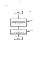
- Fig. 10 is an exemplary flow chart illustrating a process of determining the distance between the imaging mechanism and the object of interest.
- Figs. 11-13 are exemplary schematic charts for showing errors of the focal length adjustment apparatus of Fig. 1 and the compensation effect for the errors.
- a focal length adjustment apparatus and method are provided for adjusting focal length automatically and serving as a basis for a wide range of applications, such as applications on unmanned aerial vehicles (UAVs) and other mobile platforms. This result can be achieved, according to one embodiment disclosed herein, by a focal length adjustment apparatus 110 as illustrated in Fig. 1.
- Fig. 1 depicts an illustrative embodiment of a focal length adjustment apparatus 110.
- the focal length adjustment apparatus 110 can be coupled with an imaging mechanism 130.
- the imaging mechanism 130 can generate one or more images of a scene 100 where an object 120 of interest is positioned.
- FIG. 2 and Fig. 3 An example of images 199 of the scene 100 obtained by the imaging mechanism 130 are shown in Fig. 2 and Fig. 3.
- the generated images of the scene 100 can be processed by the focal length adjustment apparatus 110 to generate a signal for adjusting a focal length of the imaging mechanism 130.
- the focal length of the imaging mechanism 130 can be adjusted in any suitable manner, preferably in real time.
- the imaging mechanism 130 can comprise any suitable number of imaging devices 133.
- the imaging mechanism 130 can have 2, 3, 4, 5, 6, or even a greater number of imaging devices.
- the automatic focal length adjustment illustrated herein can be applied as to any pair of the imaging devices.
- the imaging devices 131, 132 of Fig. 1 can be arranged in any desired manner in the imaging mechanism 130.
- the specific arrangement of the imaging devices 131, 132 can depend on a relevant imaging application.
- the imaging devices 131, 132 can be positioned side-by-side so that the imaging devices 131, 132 have parallel optical axes.
- the imaging devices 131, 132 can be positioned such that the optical axes of the imaging devices 131, 132 are not parallel.
- Each of the imaging devices 131, 132 can sense light and convert the sensed light into electronic signals that can be ultimately rendered as an image.
- Exemplary imaging devices 131, 132 suitable for use with the focal length adjustment apparatus 110 include, but are not limited to, commercially-available cameras (color and/or monochrome) and camcorders.
- Suitable imaging devices 131, 132 can include analog imaging devices (for example, video camera tubes) and/or digital imaging devices (for example, charge-coupled device (CCD), complementary metal-oxide-semiconductor (CMOS), N-type metal-oxide-semiconductor (NMOS) imaging devices, and hybrids/variants thereof).
- CCD charge-coupled device
- CMOS complementary metal-oxide-semiconductor
- NMOS N-type metal-oxide-semiconductor
- Digital imaging devices can include a two-dimensional array of photosensor elements (not shown) that can each capture one pixel of image information.
- Either of the imaging devices 131, 132 can be, for example, an electro-optical sensor, a thermal/infrared sensor, a color or monochrome sensor, a multi-spectral imaging sensor, a spectrophotometer, a spectrometer, a thermometer, and/or a illuminometer.
- either of the imaging devices 131, 132 can be, for example, an Red-Green-Blue (RGB) camera, an ultrasonic camera, a laser camera, an infrared camera, an ultrasound camera or a Time-of-Flight camera.
- the imaging devices 131, 132 can be alternatively of the same type.
- the focal lengths of the imaging devices 131, 132 can be the same and/or different without limitation to the scope of the present disclosure.
- FIG. 4 An exemplary first imaging device 131 and second imaging device 132 are shown in Fig. 4.
- a distance D between the first imaging device 131 and the second imaging device 132 can be adjustable depending on an object distance Z (shown in Fig. 6) between the imaging devices 131, 132 and the object 120 of interest.
- the first imaging device 131 and the second imaging device 132 can be installed on a portable cradle head 150.
- the focal lengths of the first imaging device 131 and the second imaging device 132 can be adjusted automatically based on the object distance Z. By adjusting the focal lengths of the imaging devices 131, 132, the object 120 of interest can be made clearly visible.
- the focal length adjustment apparatus 110 (shown in Fig. 1) can be physically located adjacent to the imaging mechanism 130 (shown in Fig. 1), in which case data between the focal length adjustment apparatus 110 and the imaging mechanism 130 can be communicated locally.
- An advantage of local communication is that transmission delay can be reduced to facilitate real-time focal length adjustment, image processing, and parameter calibration.
- the focal length adjustment apparatus 110 can be located remotely from the imaging mechanism 130. Remote processing may be preferable, for example, because of weight restrictions or other reasons relating to an operational environment of the focal length adjustment apparatus 110.
- UAV unmanned aerial vehicle
- Fig. 4 illustrates an exemplary embodiment of the focal length adjustment apparatus 110, the imaging devices 131, 132 are installed on a UAV 400.
- the mobile platform can be any kind of such platforms, including but not limited to any self-stabilizing mobile platforms.
- Suitable communication methods can be used for remote communication between the imaging mechanism 130 and the focal length adjustment apparatus 110.
- Suitable communication methods include, for example, radio, Wireless Fidelity (Wi-Fi), cellular, satellite, and broadcasting.
- Exemplary wireless communication technologies include, but are not limited to, Global System for Mobile Communications (GSM), General Packet Radio Service (GPRS), Code Division Multiple Access (CDMA), Wideband CDMA (W-CDMA), CDMA2000, IMT Single Carrier, Enhanced Data Rates for GSM Evolution (EDGE), Long-Term Evolution (LTE), LTE Advanced, Time-Division LTE (TD-LTE), High Performance Radio Local Area Network (HiperLAN), High Performance Radio Wide Area Network (HiperWAN), High Performance Radio Metropolitan Area Network (HiperMAN), Local Multipoint Distribution Service (LMDS), Worldwide Interoperability for Microwave Access (WiMAX), ZigBee, Bluetooth, Flash Orthogonal Frequency-Division Multiplexing (Flash-OFDM), High Capacity Spatial Division Multiple Access (HC-
- the imaging mechanism 130 can be at least partially incorporated into the focal length adjustment apparatus 110.
- the imaging mechanism 130 thereby can advantageously serve as a component of the focal length adjustment apparatus 110.
- the imaging mechanism 130 can interface with the focal length adjustment apparatus 110.
- the imaging devices 131, 132 of the imaging mechanism 130 can acquire respective images 199 (shown in Fig. 2 and Fig. 3) of the scene 100 and relay the acquired images to the focal length adjustment apparatus 110 locally and/or remotely via a data communication system (not shown).
- the focal length adjustment apparatus 110 can be configured, for example, to reconstruct a three-dimensional depiction of the object 120 of interest using the two images via stereopsis.
- the focal length adjustment apparatus 110 thereby can determine whether a focal length adjustment would be advantageous based on the object distance Z between the imaging mechanism 130 and the object 120 of interest and/or to convey calibrating signals to the imaging mechanism 130 for a focal length adjustment.
- the focal length adjustment apparatus 110 can be advantageously configured to automatically calibrate one or more extrinsic parameters for stereoscopic imaging.
- the images 199 acquired by the imaging devices 131, 132 can include images 199A and 199B.
- the images 199A (left, indicated as l in the following equations) and 199B (right, indicated as r in the following equations) can be compared to ascertain the object distance Z between the imaging devices 131, 132 and the object 120 of interest.
- a method of triangulation can be used to ascertain the object distance Z using a binocular disparity d between the two images 199A and 199B.
- coordinates (X i , Y i , Z i ) of a pixel i in the image 199A(left) can be given as follows:
- c x and c y represent respective center coordinates of the imaging devices 131, 132, x i and y i represent the coordinates of the object 120 of interest in one or both of the images 199A (left) and 199B (right)
- T is the baseline (in other words, the distance between the center coordinates of the imaging devices 131, 132)
- f is a rectified focal length of the imaging devices 131, 132
- i is an index over multiple objects 120 of interest and/or over multiple selected points of an object 120 of interest that can be used to determine the object distance Z
- d is the binocular disparity between the images 199A(l) and 199B(r), represented here as:
- the focal length adjustment apparatus 110 can include any processing hardware and/or software needed to perform image acquisition, focal length adjustment, calibration, and any other functions and operations described herein.
- the focal length adjustment apparatus 110 can include one or more general purpose microprocessors (for example, single or multi-core processors), application-specific integrated circuits, application-specific instruction-set processors, graphics processing units, physics processing units, digital signal processing units, coprocessors, network processing units, audio processing units, encryption processing units, and the like.
- the focal length adjustment apparatus 110 can include an image processing engine or media processing unit, which can include specialized hardware for enhancing the speed and efficiency of image capture, filtering, and processing operations. Such operations include, for example, Bayer transformations, demosaicing operations, noise reduction operations, and/or image sharpening/softening operations.
- the focal length adjustment apparatus 110 can include specialized hardware and/or software for performing focal length adjustment and parameter calibration.
- specialized hardware and/or software can be provided for functions including, but are not limited to, reconstructing a three-dimensional depiction of the object 120 of interest using the two-dimensional images via stereopsis, determining whether a focal length adjustment is needed based on a distance between the imaging mechanism 130 and the object 120 of interest, determining an optimal focal length, conveying control signals to any components of the focal length adjustment apparatus 110 for focal length adjustment.
- the focal length adjustment apparatus 110 can include one or more additional hardware components (not shown), as desired.
- additional hardware components include, but are not limited to, memories (for example, a random access memory (RAM), static RAM, dynamic RAM, read-only memory (ROM), programmable ROM, erasable programmable ROM, electrically erasable programmable ROM, flash memory, secure digital (SD) card, etc.), and/or one or more input/output interfaces (for example, universal serial bus (USB), digital visual interface (DVI), display port, serial ATA (SATA), IEEE 1394 interface (also known as FireWire), serial, video graphics array (VGA), super video graphics array (SVGA), small computer system interface (SCSI), high-definition multimedia interface (HDMI), audio ports, and/or proprietary input/output interfaces).
- one or more input/output devices for example, buttons, a keyboard, keypad, trackball, displays, and a monitor
- the image acquisition, focal length adjustment, calibration, and any other functions and operations described herein for the focal length adjustment apparatus 110 can be achieved by software running on a conventional processor or a general purpose computer, such as a personal computer.
- the software can be operated with suitable hardware discussed above as desired.
- the software for example, can take any form of source code, object code, executable code and machine readable code.
- the source code can be written in any form of high-level programming languages, including but not limited to, C++, Java, Pascal, Visual B and the like.
- the focal length adjustment apparatus 110 of Fig. 7 comprises a distance assembly 701 for determining the object distance Z, that is, a distance between the object 120 of interest in the scene 100 and the imaging mechanism 130.
- the focal length adjustment apparatus 110 further includes a focal length assembly 702 configured to automatically adjust the focal length of the imaging mechanism 130 according to the determined distance by the distance assembly 701.
- the distance assembly 701 is shown as comprising a depth estimation mechanism 7011 for obtaining a depth map of the scene 100, an object determination mechanism 7012 for determining the object 120 of interest in the scene 100 and a calculating mechanism 7013 for calculating distance of the object 120 of interest according to the depth map of the scene 100 from depth estimation mechanism 7011.
- the depth estimation mechanism 7011 receives a first image 199A (shown in Fig. 2) of the scene 100 from the first imaging device 131 and a second image 199B (shown in Fig. 3) of the scene 100 from the second imaging device 132. Based on the first image 199A and the second image 199B of the scene 100 as shown in Figs. 2 and 3, the depth estimation mechanism 7011 obtains their disparity, based on which a depth map 800 (shown in Fig. 8) is acquired. The specific operation of the depth estimation mechanism 7011 for obtaining the depth map will be described in detail below with reference to Fig. 8.
- An exemplary depth map 800 is depicted in Fig. 8.
- Each pixel (not shown) in the depth map 800 is associated with a value that represents a distance between the point corresponding to the pixel in the scene 100 (shown in Fig. 1) and the imaging mechanism 130 (shown in Fig. 1).
- a brightness value is utilized to represent a distance between a point in the scene (either on the object 120 of interest or not on the object 120 of interest) and an imaging device which images the scene.
- different color values can be assigned to pixels to represent the distance.
- a brighter area 810 indicates points in the scene 100 with nearer distances to the imaging mechanism 130 (shown in Fig.
- a darker area 820 indicates points in the scene 100 with further distances to the imaging mechanism 130
- a grey area 830 indicates points in the scene 100 with distances between the near and far distance. If the object 120 of interest moves in the scene 100, a brightness of the pixels for the object 120 of interest can vary based upon the distance between the object 120 of interest and the imaging mechanism 130. The selected pixels for the object 120 of interest can become brighter when the distance between the object 120 of interest and the imaging mechanism 130 decreases and can become dimmer when the distance increases as shown in Fig. 8.
- the object determination mechanism 7012 can receive outside instructions to determine the object 120 (shown in Fig. 1) of interest by identifying the object 120 of interest selected in either of the first and the second images of the scene 100 (shown in Fig. 1). Outside instructions can be given by, for example, operators of the focal length adjustment apparatus 110.
- the selection of the object 120 of interest can be done by framing in the object 120 of interest in either of the first and the second images of the scene 100.
- the first and the second images of the scene 100 can be displayed on a display screen (not shown) and/or on a display screen (not shown) to the operator of the focal length adjustment apparatus 110 for selection.
- the selection of the object 120 of interest can be performed by clicking the display screen(s) on the object 120 of interest in either of the first and the second images of the scene 100 displayed on the display screen(s).
- the object determination mechanism 7012 can sense the framing and/or the clicking operation to identify the object 120 of interest being selected.
- the object determination mechanism 7012 enables to receive outside oral instructions from, for example, an operator of the focal length adjustment apparatus 110.
- the oral instructions can be a pre-set name of the object 120 of interest.
- the object determination mechanism 7012 can be enabled to automatically determine the object 120 of interest based on a judgment under at least a pre-set rule. Any rule for the judgment can be set as desired.
- the pre-set rule may comprise that the object 120 of interest is determined if the object 120 of interest is approaching the first and the second imaging devices 131, 132 and/or if the object 120 of interest is within a certain distance from the first and the second imaging devices 131, 132.
- the calculating mechanism 7013 can be enabled to calculate the distance between the imaging mechanism 130 and the object 120 of interest.
- the calculating mechanism 7013 preferably calculates the distance in real time.
- the focal length assembly 702 can be enabled to automatically adjust the focal length of the imaging mechanism 130, preferably in real time, with a tracking learning detection method based on gray level information of the object 120 of interest serving as initial values.
- the object determination mechanism 7012 can enable the user to draw a frame on the display showing the images of the scene 100 to frame in the object 120 of interest to be tracked.
- the frame can be in any suitable dimension, size or shape, including, but not limited to, a shape of a rectangular, a square or a circle or even an irregular shape.
- the user can be enabled to click the display screen(s) to confirm the selection.
- the depth map 800 shown in Fig.
- the calculating mechanism 7013 can be enabled to calculate the distance of the object being selected by the user and the focal length assembly 702 enables to adjust the focal length of the focal length adjustment apparatus 110 automatically according to the object distance Z (shown in Fig. 6), which distance preferably is acquired in real time.
- an object distance between the imaging mechanism 130 (shown in Fig. 1) and the object 120 (shown in Fig. 1) of interest is determined.
- the object distance Z (shown in Fig. 6) can be determined by using any of several various methods, as desired.
- the object distance Z can be determined by using a plurality of imaging devices 133 (shown in Fig. 1) in the imaging mechanism 130 via stereopsis. For example, two imaging devices 131, 132 (shown in Fig. 1) of the imaging mechanism 130 each can acquire an image (shown in Figs.
- the object distance can be acquired using one or more non-stereopsis methods, such as by using a laser and/or using ultrasound.
- the focal length of the imaging mechanism 130 is automatically adjusted according to the object distance Z determined in step 901.
- a detailed process 901 of determining the distance between the imaging mechanism 130 and the object 120 of interest is illustrated in Fig. 10.
- a depth map of the scene 100 is obtained. Any process of obtaining a depth map may be applied here without limitation. An exemplary process is illustrated in details below.
- a depth map is obtained by calculating a disparity of scene images from the first and second imaging devices 131, 132.
- an energy function is usually computed over a subset of the whole image.
- a global energy function is optimized to obtain a disparity global energy.
- the disparity global energy can be calculated by summing a disparity energy function and a scaled smoothing term.
- d indicates the disparity between the first and the images of the scene
- Ed(d) is a data term, which indicates the disparity energy function
- E s (d) indicates a smoothing term
- the data term E d (d) comprises a Birchfield-Tomasi data term which can be obtained in accordance with the equation:
- I L represents the first image of the scene 100 captured by the first imaging device 131 and I R represents the second image of the scene 100 captured by the second imaging device 132 respectively;
- x in I L (x) represents a horizontal coordinate of a pixel in the first image and
- x ’ in I L (x ’ ) represents a horizontal coordinate of the pixel in the second image;
- (x, y) represents coordinates of a pixel in the scene 100.
- Birchfield-Tomasi data term which is a data term often used in image sampling/matching resolves a problem of incorrect image matching by utilizing a matching precision of sub pixels, which is a pixel dissimilarity measure that is insensitive to image sampling.
- the contents of IEEE Transactions on Pattern Analysis and Machine Intelligence (1998) explaining the Birchfield-Tomasi data term is incorporated here by reference.
- Other data terms may be adopted as the data term in Equation 5 when calculating the disparity global energy.
- the smoothing term E s (d) can be presented by an energy function of differential of disparity, which can be obtained by, for all neighbors of a pixel with the coordination of (x, y), summing scaled trigger functions of a disparity between two neighboring pixels.
- the smoothing term E s (d) can be obtained in accordance with the equation as follows:
- (x, y) represents the coordinates of the pixel of the first image and (x ’ , y ’ ) represents the coordinates of the pixel of the second image;
- p 2 and p 1 are two adjustable weights, and usually p 2 ⁇ p 1 and the summation sign is for all neighbors of (x, y) in which four domains are usually used,
- T is a trigger function which is triggered when the conditions in the parentheses are true.
- a fastest dynamic planning is utilized by aggregating data terms in a plurality of directions to obtain a directional energy function for each of the directions and accumulating the directional energy functions in the directions to obtain the energy function.
- four or eight directions are selected to aggregate data terms.
- Other numbers of directions, such as three, five or ten directions, can be selected without limitation.
- an energy function in one direction can be obtained by summing its corresponding smoothing term and the dynamic planning in this direction.
- a dynamic planning in one direction can be presented by a recurrence based on the energy functions of its neighbors in this direction. For example, energy functions of one pixel’s neighbors in the horizontal direction are presented as L(x-1, y, d), L(x-1, y, d+1), L(x-1, y, d-1), and L(x-1, y, d ’ ).
- an energy function in horizontal direction is obtained in accordance with the equation:
- the energy received at the coordinates (x, y, d) is defined as L(x, y, d), which is presented as a recurrence based on the energy of neighbors L(x-1, y, d), L(x-1, y, d+1), L(x-1, y, d-1), and L(x-1, y, d ’ ).
- a best depth is obtained by seeking the disparity value that minimizes the summation of energy in a plurality of directions.
- the best depth is obtained in accordance with the equation:
- d * indicates the best depth
- L(x, y, d) indicates an energy function in one direction.
- some noise is reduced by matching the first and second scene images and/or identifying respective unique features of the first and second scene images while setting the disparity as -1.
- the present disclosure also optimizes the depth map obtained by the depth estimation mechanism 7011.
- the global energy function is optimized by compensating errors of the depth estimation mechanism 7011.
- the errors can be compensated by following equations:
- a baseline (the distance between the central lines of the two imaging devices, mm)
- the depth estimation errors are within a range of [-x, x], and the estimated depth is in a range of .
- the above error analysis and the compensation are based on following assumptions.
- the error estimation is based on an assumption that camera calibration parameters are completely correct and an average error of the disparity map is a theoretical value for 1 pixel.
- An actual calibration can introduce errors, and a depth estimation error may exceed 1 pixel. Therefore, the above data of errors reflects a trend only.
- FIGs. 11-13 A few schematic charts showing the errors of the focal length adjustment apparatus 110 and the compensation effect for the errors are depicted in Figs. 11-13.
- Fig. 11 illustrates an exemplary relationship between the estimated error of the focal length adjustment apparatus 100 and the measured depth D of the scene 100 when only the measured depth D varies.
- the baseline a the distance of two adjacent pixels b and the focal length f of the equations 16, 17 remain constant as the measured depth D changes.
- a horizontal axis represents a measured depth D in mm
- a vertical axis represents the estimated error of the focal length adjustment apparatus 110.
- the estimated error of the focal length adjustment apparatus 100 also changes in a non-linear relationship with reference to the measured depth D. For example, when the measured depth D is 3000mm, the estimated error according to Fig. 11 is about 5mm, but when the measured depth D increases to 6000mm, the corresponding estimated error increases to over 20mm.
- the relationship of the estimated error and the measured depth D can be any linear and/or non-linear relationships.
- Fig. 12 illustrates an exemplary relationship between the estimated error of the focal length adjustment apparatus 100 and the baseline when only the baseline a varies.
- the measured depth D, the distance of two adjacent pixels b and the focal length f of the equations 16, 17 remain constant when the baseline a changes.
- a horizontal axis represents the baseline a in mm
- a vertical axis represents the estimated error in mm.
- the estimated error can decrease by in accordance with a non-linear relationship between the estimated error and the baseline a.
- the estimated error according to Fig. 12 can be as high as 35mm, but when the baseline a increases to 2000mm, the estimated error decreases to about 8mm.
- the relationship of the estimated error and the baseline can be any linear and/or non-linear relationships.
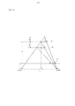
- Fig. 13 is an illustrative example for showing representative corresponding relationships among the image representation symbols and the variables contained in the Equations 14-19.
- Equations 14-19 can be deducted from the represented relationships illustrated in Fig. 13.
- the imaging devices 131, 132 shown in Fig. 1 are represented with two cameras, Cam1 and Cam2, which have a baseline “a” and a focus length “f”.
- Equation 14 As shown in Fig. 13, triangles ABO 2 and CBO 2 are similar because AB is parallel to CD. Therefore, we can get Equation 14: .
- triangles ADE and O 1 O 2 E are similar because CD is parallel to O 1 O 2 . Therefore, we can get Equation 15: .
- Equation 16 By combining Equations 14 and 15, we can reach Equation 16: .
- Equation 19 can be deducted from a combination of a similarity relationship of triangles AHO 2 and a similarity relationship of FGO 2 and O 1 O 2 C.
- D is the actual depth between the scene 100 and the imaging plane
- a is the baseline between the two image devices 131, 132
- b is the distance of two adjacent pixels
- f is the focal length of the imaging devises 131, 132, as shown in Fig. 13.
- the estimated errors –x and +x can be different absolute values as results of equations 16 and 19, in which case, b can carry different values in each equation.
- the depth map can be further optimized by applying a non-partial optimizing equation whose Jacobi iteration can be obtained by a recurrence filtering.
- the non-partial optimizing equation is defined in accordance with the following equation:
- d * (x, y) indicates the optimal depth map and d(x,y) is the estimated depth map;
- I(x,y) represents the intensity of the image;
- x,y are the coordinates of the pixel in an image coordinate;
- x / ,y / are the coordinates of an adjacent pixel of x,y in the same image.
- step 9012 of Fig. 10 the object 120 of interest is determined and the distance between the object 120 of interest and the imaging mechanism 130 is calculated in step 9013 of Fig. 10, which in turn serves as a basis for automatically adjusting the focal length of the imaging mechanism 130.
- a stereoscopic imaging system configured to conduct the aforementioned operations to perform automatic focal length adjustment can be obtained according to any embodiment of the present disclosure.
- a computer program product comprising instructions for automatically adjusting focal length of a stereoscopic imaging system having at least two imaging devices in accordance with the aforementioned operations can be obtained according to an embodiment of the present disclosure.
- the method for automatically adjusting focal length according to the present disclosure can be achieved by an ordinary computing device, such as a personal computer and/or a microcomputer.
Landscapes
- Engineering & Computer Science (AREA)
- Multimedia (AREA)
- Signal Processing (AREA)
- Theoretical Computer Science (AREA)
- Computer Vision & Pattern Recognition (AREA)
- Physics & Mathematics (AREA)
- General Physics & Mathematics (AREA)
- Computing Systems (AREA)
- Image Processing (AREA)
- Studio Devices (AREA)
- Measurement Of Optical Distance (AREA)
Abstract
L'invention concerne un appareil et des procédés de réglage de longueur focale et de détermination d'une carte de profondeur, qui permettent de créer et d'utiliser ladite carte. L'appareil de réglage de longueur focale comprend un ensemble de distance configuré pour déterminer une distance entre un objet d'intérêt et un mécanisme d'imagerie pour imager l'objet d'intérêt. L'appareil de réglage de longueur focale peut également comprendre un ensemble de longueur focale configuré pour régler automatiquement une longueur focale du mécanisme d'imagerie selon la distance déterminée. L'appareil de réglage de longueur focale permet d'obtenir avantageusement un réglage de longueur focale automatique, à coût plus faible par comparaison avec des solutions à l'aide de caméras laser.
Priority Applications (6)
| Application Number | Priority Date | Filing Date | Title |
|---|---|---|---|
| CN202010110338.8A CN111371986A (zh) | 2015-03-16 | 2015-03-16 | 用于焦距调节和深度图确定的装置和方法 |
| CN201580077679.7A CN107409205B (zh) | 2015-03-16 | 2015-03-16 | 用于焦距调节和深度图确定的装置和方法 |
| PCT/CN2015/074336 WO2016145602A1 (fr) | 2015-03-16 | 2015-03-16 | Appareil et procédé de réglage de longueur focale et de détermination d'une carte de profondeur |
| EP15874398.9A EP3108653A4 (fr) | 2015-03-16 | 2015-03-16 | Appareil et procédé de réglage de longueur focale et de détermination d'une carte de profondeur |
| US15/701,041 US10574970B2 (en) | 2015-03-16 | 2017-09-11 | Apparatus and method for focal length adjustment and depth map determination |
| US16/799,475 US20200195908A1 (en) | 2015-03-16 | 2020-02-24 | Apparatus and method for focal length adjustment and depth map determination |
Applications Claiming Priority (1)
| Application Number | Priority Date | Filing Date | Title |
|---|---|---|---|
| PCT/CN2015/074336 WO2016145602A1 (fr) | 2015-03-16 | 2015-03-16 | Appareil et procédé de réglage de longueur focale et de détermination d'une carte de profondeur |
Related Child Applications (1)
| Application Number | Title | Priority Date | Filing Date |
|---|---|---|---|
| US15/701,041 Continuation US10574970B2 (en) | 2015-03-16 | 2017-09-11 | Apparatus and method for focal length adjustment and depth map determination |
Publications (1)
| Publication Number | Publication Date |
|---|---|
| WO2016145602A1 true WO2016145602A1 (fr) | 2016-09-22 |
Family
ID=56918392
Family Applications (1)
| Application Number | Title | Priority Date | Filing Date |
|---|---|---|---|
| PCT/CN2015/074336 WO2016145602A1 (fr) | 2015-03-16 | 2015-03-16 | Appareil et procédé de réglage de longueur focale et de détermination d'une carte de profondeur |
Country Status (4)
| Country | Link |
|---|---|
| US (2) | US10574970B2 (fr) |
| EP (1) | EP3108653A4 (fr) |
| CN (2) | CN107409205B (fr) |
| WO (1) | WO2016145602A1 (fr) |
Families Citing this family (12)
| Publication number | Priority date | Publication date | Assignee | Title |
|---|---|---|---|---|
| DK3195076T3 (da) | 2015-06-26 | 2021-03-22 | Sz Dji Technology Co Ltd | System og fremgangsmåde til valg af en driftstilstand for en mobil platform |
| EP3591490B1 (fr) * | 2017-12-15 | 2021-12-01 | Autel Robotics Co., Ltd. | Procédé et dispositif d'évitement d'obstacle, et véhicule aérien autonome |
| CN108989687A (zh) * | 2018-09-07 | 2018-12-11 | 北京小米移动软件有限公司 | 摄像头对焦方法及装置 |
| CN109856015B (zh) * | 2018-11-26 | 2021-08-17 | 深圳辉煌耀强科技有限公司 | 一种癌细胞自动诊断的快速处理方法及其系统 |
| CN109451241B (zh) * | 2018-12-10 | 2021-06-18 | 无锡祥生医疗科技股份有限公司 | 超声图像的焦点自动调节方法及装置 |
| JP6798072B2 (ja) * | 2019-04-24 | 2020-12-09 | エスゼット ディージェイアイ テクノロジー カンパニー リミテッドSz Dji Technology Co.,Ltd | 制御装置、移動体、制御方法、及びプログラム |
| CN110225249B (zh) * | 2019-05-30 | 2021-04-06 | 深圳市道通智能航空技术有限公司 | 一种对焦方法、装置、航拍相机以及无人飞行器 |
| US10895637B1 (en) * | 2019-07-17 | 2021-01-19 | BGA Technology LLC | Systems and methods for mapping manmade objects buried in subterranean surfaces using an unmanned aerial vehicle integrated with radar sensor equipment |
| WO2021026754A1 (fr) * | 2019-08-13 | 2021-02-18 | 深圳市大疆创新科技有限公司 | Procédé et appareil de commande de mise au point pour appareil de photographie, et aéronef sans pilote |
| CN111579082B (zh) * | 2020-05-09 | 2021-07-30 | 上海交通大学 | 红外热成像测温系统的误差自动补偿方法 |
| US20220021822A1 (en) * | 2020-07-14 | 2022-01-20 | International Business Machines Corporation | Guided multi-spectral inspection |
| CN116507970A (zh) * | 2021-01-07 | 2023-07-28 | 深圳市大疆创新科技有限公司 | 跟焦方法、装置、拍摄设备及计算机可读存储介质 |
Citations (6)
| Publication number | Priority date | Publication date | Assignee | Title |
|---|---|---|---|---|
| CN101243458A (zh) * | 2005-08-15 | 2008-08-13 | 索尼电子有限公司 | 创建深度图的图像获取系统 |
| CN101840146A (zh) * | 2010-04-20 | 2010-09-22 | 夏佳梁 | 自动矫正视差的立体图像拍摄方法及装置 |
| US20120327195A1 (en) | 2011-06-24 | 2012-12-27 | Mstar Semiconductor, Inc. | Auto Focusing Method and Apparatus |
| CN103350281A (zh) * | 2013-06-20 | 2013-10-16 | 深圳市大族激光科技股份有限公司 | 激光打标机自动调焦装置及自动调焦方法 |
| US20140307054A1 (en) | 2013-04-11 | 2014-10-16 | Altek Semiconductor Corp. | Auto focus method and auto focus apparatus |
| US20140347456A1 (en) * | 2013-05-21 | 2014-11-27 | Panasonic Corporation | Viewer with varifocal lens and video display system |
Family Cites Families (21)
| Publication number | Priority date | Publication date | Assignee | Title |
|---|---|---|---|---|
| US6148270A (en) | 1996-10-30 | 2000-11-14 | Yamatake-Honeywell Co., Ltd. | Fast target distance measuring device and high-speed moving image measuring device |
| US6701081B1 (en) | 2000-06-06 | 2004-03-02 | Air Controls, Inc. | Dual camera mount for stereo imaging |
| WO2007050776A2 (fr) | 2005-10-25 | 2007-05-03 | University Of Kentucky Research Foundation | Systeme et procede d'imagerie 3d utilisant l'eclairage en lumiere structuree |
| EP2293588A1 (fr) | 2009-08-31 | 2011-03-09 | Robert Bosch GmbH | Procédé d'utilisation d'un agencement de caméra de stéréovision |
| EP2336027A1 (fr) | 2009-12-18 | 2011-06-22 | EADS Construcciones Aeronauticas, S.A. | Procédé et dispositif pour améliorer le champ de vision lors du ravitaillement en vol |
| CN102117576A (zh) | 2009-12-31 | 2011-07-06 | 鸿富锦精密工业(深圳)有限公司 | 电子相框 |
| CN201803697U (zh) | 2010-06-03 | 2011-04-20 | 蒋安邦 | 双摄像头对移动光源目标在三维空间位置确定的传感器 |
| KR101012691B1 (ko) | 2010-07-05 | 2011-02-09 | 주훈 | 3차원 입체 열상 카메라 시스템 |
| JP5870510B2 (ja) | 2010-09-14 | 2016-03-01 | 株式会社リコー | ステレオカメラ装置、校正方法およびプログラム |
| KR20120070129A (ko) | 2010-12-21 | 2012-06-29 | 한국전자통신연구원 | 입체 영상 촬영 장치 및 그 방법 |
| CN102592117B (zh) | 2011-12-30 | 2014-04-16 | 杭州士兰微电子股份有限公司 | 三维物体识别方法及系统 |
| CN102609936A (zh) * | 2012-01-10 | 2012-07-25 | 四川长虹电器股份有限公司 | 基于置信度传播的图像立体匹配方法 |
| CN102591532B (zh) | 2012-01-22 | 2015-01-21 | 南京先能光电科技有限公司 | 双反射镜交叉定位电子白板装置 |
| US9230306B2 (en) * | 2012-02-07 | 2016-01-05 | Semiconductor Components Industries, Llc | System for reducing depth of field with digital image processing |
| CN102779274B (zh) | 2012-07-19 | 2015-02-25 | 冠捷显示科技(厦门)有限公司 | 一种基于双目摄像头的智能电视人脸识别方法 |
| US20150010236A1 (en) * | 2013-07-08 | 2015-01-08 | Htc Corporation | Automatic image refocusing method |
| CN103595916A (zh) | 2013-11-11 | 2014-02-19 | 南京邮电大学 | 一种双摄像头目标跟踪系统及其实现方法 |
| US9571819B1 (en) * | 2014-09-16 | 2017-02-14 | Google Inc. | Efficient dense stereo computation |
| KR102251483B1 (ko) * | 2014-10-23 | 2021-05-14 | 삼성전자주식회사 | 영상을 처리하는 전자 장치 및 방법 |
| US9704250B1 (en) * | 2014-10-30 | 2017-07-11 | Amazon Technologies, Inc. | Image optimization techniques using depth planes |
| US9292926B1 (en) * | 2014-11-24 | 2016-03-22 | Adobe Systems Incorporated | Depth map generation |
-
2015
- 2015-03-16 CN CN201580077679.7A patent/CN107409205B/zh not_active Expired - Fee Related
- 2015-03-16 EP EP15874398.9A patent/EP3108653A4/fr not_active Withdrawn
- 2015-03-16 CN CN202010110338.8A patent/CN111371986A/zh active Pending
- 2015-03-16 WO PCT/CN2015/074336 patent/WO2016145602A1/fr active Application Filing
-
2017
- 2017-09-11 US US15/701,041 patent/US10574970B2/en not_active Expired - Fee Related
-
2020
- 2020-02-24 US US16/799,475 patent/US20200195908A1/en not_active Abandoned
Patent Citations (6)
| Publication number | Priority date | Publication date | Assignee | Title |
|---|---|---|---|---|
| CN101243458A (zh) * | 2005-08-15 | 2008-08-13 | 索尼电子有限公司 | 创建深度图的图像获取系统 |
| CN101840146A (zh) * | 2010-04-20 | 2010-09-22 | 夏佳梁 | 自动矫正视差的立体图像拍摄方法及装置 |
| US20120327195A1 (en) | 2011-06-24 | 2012-12-27 | Mstar Semiconductor, Inc. | Auto Focusing Method and Apparatus |
| US20140307054A1 (en) | 2013-04-11 | 2014-10-16 | Altek Semiconductor Corp. | Auto focus method and auto focus apparatus |
| US20140347456A1 (en) * | 2013-05-21 | 2014-11-27 | Panasonic Corporation | Viewer with varifocal lens and video display system |
| CN103350281A (zh) * | 2013-06-20 | 2013-10-16 | 深圳市大族激光科技股份有限公司 | 激光打标机自动调焦装置及自动调焦方法 |
Non-Patent Citations (6)
| Title |
|---|
| C. BANZ ET AL.: "EVALUATION OF PENALTY FUNCTIONS FOR SEMI-GLOBAL MATCHING COST AGGREGATION", ISPRS - INTERNATIONAL ARCHIVES OF THE PHOTOGRAMMETRY, REMOTE SENSING AND SPATIAL INFORMATION SCIENCES, vol. XXXIX-BB, 25 August 2012 (2012-08-25) |
| KUMAR A KIRAN ET AL., DEPTH AND ZOOM ESTIMATION FOR PTZ CAMERA USING STEREO VISION, 1 May 2014 (2014-05-01) |
| See also references of EP3108653A4 |
| STAN BIRCHFIELD AND CARLO TOMASI ED - BOYKOV YURI: "INTERNATIONAL JOURNAL OF COMPUTER VISION", vol. 35, 1 January 1999, KLUWER ACADEMIC PUBLISHERS, article "Depth Discontinuities by Pixel-to—Pixel Stereo", pages: 269 - 293 |
| YAN GAO ET AL.: "INTELLIGENT", 7 July 2010, IEEE, article "Zoom control of wide area tracking system", pages: 402 - 407 |
| YAN GAO: "ONFERENCE ON", 5 October 2010, IEEE, article "Active zoom cameras control system using stereo parallax", pages: 418 - 424 |
Also Published As
| Publication number | Publication date |
|---|---|
| EP3108653A1 (fr) | 2016-12-28 |
| US10574970B2 (en) | 2020-02-25 |
| EP3108653A4 (fr) | 2016-12-28 |
| US20170374354A1 (en) | 2017-12-28 |
| CN111371986A (zh) | 2020-07-03 |
| CN107409205A (zh) | 2017-11-28 |
| CN107409205B (zh) | 2020-03-20 |
| US20200195908A1 (en) | 2020-06-18 |
Similar Documents
| Publication | Publication Date | Title |
|---|---|---|
| WO2016145602A1 (fr) | Appareil et procédé de réglage de longueur focale et de détermination d'une carte de profondeur | |
| WO2016086379A1 (fr) | Système et procédé d'imagerie | |
| WO2015152692A1 (fr) | Appareil et procédé de génération d'image périphérique de véhicule | |
| WO2012064106A2 (fr) | Procédé et appareil de stabilisation de vidéo par compensation de direction de visée de caméra | |
| WO2017018612A1 (fr) | Procédé et dispositif électronique pour stabiliser une vidéo | |
| WO2012086966A2 (fr) | Procédé d'utilisation d'un dispositif de communication sans fil pour capturer facilement une image de qualité d'un iris et d'un sujet, et appareil de prise de vues transmettant une gamme partielle de rayons visibles et de rayons infrarouges proches à travers un filtre passe-bande simple | |
| WO2015152691A2 (fr) | Appareil et procédé de génération d'une image autour d'un véhicule | |
| EP3120539A1 (fr) | Appareil photographique, son procédé de commande, et support d'enregistrement lisible par ordinateur | |
| WO2017008246A1 (fr) | Procédé, appareil et système pour déterminer un mouvement d'une plateforme mobile | |
| WO2015126044A1 (fr) | Procédé de traitement d'image et appareil électronique associé | |
| WO2014058086A1 (fr) | Dispositif de traitement d'image et procédé de traitement d'image | |
| WO2017090833A1 (fr) | Dispositif de prise de vues, et procédé de commande associé | |
| WO2016206107A1 (fr) | Système et procédé de sélection d'un mode de fonctionnement d'une plate-forme mobile | |
| WO2020054949A1 (fr) | Dispositif électronique et procédé de capture de vue | |
| WO2018070844A1 (fr) | Procédé de réglage de bord flou pour modélisation de bord | |
| WO2017018614A1 (fr) | Procédé d'imagerie d'objet mobile et dispositif d'imagerie | |
| EP4320472A1 (fr) | Dispositif et procédé de mise au point automatique prédite sur un objet | |
| WO2019164312A1 (fr) | Module de caméra et son procédé de traitement d'image à super-résolution | |
| WO2022124607A1 (fr) | Procédé d'estimation de profondeur, dispositif, équipement électronique et support de stockage lisible par ordinateur | |
| WO2020091347A1 (fr) | Dispositif et procédé de mesure de profondeur tridimensionnelle | |
| WO2023063679A1 (fr) | Dispositif et procédé de mise au point automatique prédite sur un objet | |
| WO2022103121A1 (fr) | Dispositif électronique d'estimation d'illuminant de caméra et procédé associé | |
| WO2023055033A1 (fr) | Procédé et appareil pour l'amélioration de détails de texture d'images | |
| EP2992503A1 (fr) | Appareil et procédé de génération de données d'image dans un terminal portable | |
| WO2021246758A1 (fr) | Dispositif électronique et son procédé de fonctionnement |
Legal Events
| Date | Code | Title | Description |
|---|---|---|---|
| REEP | Request for entry into the european phase |
Ref document number: 2015874398 Country of ref document: EP |
|
| WWE | Wipo information: entry into national phase |
Ref document number: 2015874398 Country of ref document: EP |
|
| 121 | Ep: the epo has been informed by wipo that ep was designated in this application |
Ref document number: 15874398 Country of ref document: EP Kind code of ref document: A1 |
|
| NENP | Non-entry into the national phase |
Ref country code: DE |