WO2016143345A1 - 高強度極厚鋼板およびその製造方法 - Google Patents
高強度極厚鋼板およびその製造方法 Download PDFInfo
- Publication number
- WO2016143345A1 WO2016143345A1 PCT/JP2016/001311 JP2016001311W WO2016143345A1 WO 2016143345 A1 WO2016143345 A1 WO 2016143345A1 JP 2016001311 W JP2016001311 W JP 2016001311W WO 2016143345 A1 WO2016143345 A1 WO 2016143345A1
- Authority
- WO
- WIPO (PCT)
- Prior art keywords
- less
- temperature
- strength
- thick steel
- thickness
- Prior art date
- Legal status (The legal status is an assumption and is not a legal conclusion. Google has not performed a legal analysis and makes no representation as to the accuracy of the status listed.)
- Ceased
Links
Classifications
-
- C—CHEMISTRY; METALLURGY
- C21—METALLURGY OF IRON
- C21D—MODIFYING THE PHYSICAL STRUCTURE OF FERROUS METALS; GENERAL DEVICES FOR HEAT TREATMENT OF FERROUS OR NON-FERROUS METALS OR ALLOYS; MAKING METAL MALLEABLE, e.g. BY DECARBURISATION OR TEMPERING
- C21D8/00—Modifying the physical properties of ferrous metals or ferrous alloys by deformation combined with, or followed by, heat treatment
- C21D8/02—Modifying the physical properties of ferrous metals or ferrous alloys by deformation combined with, or followed by, heat treatment during manufacturing of plates or strips
-
- C—CHEMISTRY; METALLURGY
- C22—METALLURGY; FERROUS OR NON-FERROUS ALLOYS; TREATMENT OF ALLOYS OR NON-FERROUS METALS
- C22C—ALLOYS
- C22C38/00—Ferrous alloys, e.g. steel alloys
- C22C38/14—Ferrous alloys, e.g. steel alloys containing titanium or zirconium
-
- C—CHEMISTRY; METALLURGY
- C21—METALLURGY OF IRON
- C21D—MODIFYING THE PHYSICAL STRUCTURE OF FERROUS METALS; GENERAL DEVICES FOR HEAT TREATMENT OF FERROUS OR NON-FERROUS METALS OR ALLOYS; MAKING METAL MALLEABLE, e.g. BY DECARBURISATION OR TEMPERING
- C21D8/00—Modifying the physical properties of ferrous metals or ferrous alloys by deformation combined with, or followed by, heat treatment
- C21D8/02—Modifying the physical properties of ferrous metals or ferrous alloys by deformation combined with, or followed by, heat treatment during manufacturing of plates or strips
- C21D8/0221—Modifying the physical properties of ferrous metals or ferrous alloys by deformation combined with, or followed by, heat treatment during manufacturing of plates or strips characterised by the working steps
- C21D8/0226—Hot rolling
-
- C—CHEMISTRY; METALLURGY
- C21—METALLURGY OF IRON
- C21D—MODIFYING THE PHYSICAL STRUCTURE OF FERROUS METALS; GENERAL DEVICES FOR HEAT TREATMENT OF FERROUS OR NON-FERROUS METALS OR ALLOYS; MAKING METAL MALLEABLE, e.g. BY DECARBURISATION OR TEMPERING
- C21D8/00—Modifying the physical properties of ferrous metals or ferrous alloys by deformation combined with, or followed by, heat treatment
- C21D8/02—Modifying the physical properties of ferrous metals or ferrous alloys by deformation combined with, or followed by, heat treatment during manufacturing of plates or strips
- C21D8/0247—Modifying the physical properties of ferrous metals or ferrous alloys by deformation combined with, or followed by, heat treatment during manufacturing of plates or strips characterised by the heat treatment
- C21D8/0263—Modifying the physical properties of ferrous metals or ferrous alloys by deformation combined with, or followed by, heat treatment during manufacturing of plates or strips characterised by the heat treatment following hot rolling
-
- C—CHEMISTRY; METALLURGY
- C21—METALLURGY OF IRON
- C21D—MODIFYING THE PHYSICAL STRUCTURE OF FERROUS METALS; GENERAL DEVICES FOR HEAT TREATMENT OF FERROUS OR NON-FERROUS METALS OR ALLOYS; MAKING METAL MALLEABLE, e.g. BY DECARBURISATION OR TEMPERING
- C21D9/00—Heat treatment, e.g. annealing, hardening, quenching or tempering, adapted for particular articles; Furnaces therefor
- C21D9/46—Heat treatment, e.g. annealing, hardening, quenching or tempering, adapted for particular articles; Furnaces therefor for sheet metals
-
- C—CHEMISTRY; METALLURGY
- C22—METALLURGY; FERROUS OR NON-FERROUS ALLOYS; TREATMENT OF ALLOYS OR NON-FERROUS METALS
- C22C—ALLOYS
- C22C38/00—Ferrous alloys, e.g. steel alloys
- C22C38/08—Ferrous alloys, e.g. steel alloys containing nickel
-
- C—CHEMISTRY; METALLURGY
- C22—METALLURGY; FERROUS OR NON-FERROUS ALLOYS; TREATMENT OF ALLOYS OR NON-FERROUS METALS
- C22C—ALLOYS
- C22C38/00—Ferrous alloys, e.g. steel alloys
- C22C38/18—Ferrous alloys, e.g. steel alloys containing chromium
- C22C38/40—Ferrous alloys, e.g. steel alloys containing chromium with nickel
- C22C38/58—Ferrous alloys, e.g. steel alloys containing chromium with nickel with more than 1.5% by weight of manganese
-
- C—CHEMISTRY; METALLURGY
- C21—METALLURGY OF IRON
- C21D—MODIFYING THE PHYSICAL STRUCTURE OF FERROUS METALS; GENERAL DEVICES FOR HEAT TREATMENT OF FERROUS OR NON-FERROUS METALS OR ALLOYS; MAKING METAL MALLEABLE, e.g. BY DECARBURISATION OR TEMPERING
- C21D2211/00—Microstructure comprising significant phases
- C21D2211/001—Austenite
Definitions
- the present invention relates to a high-strength extra-thick steel plate excellent in brittle crack propagation stopping characteristics, having a plate thickness of 70 mm or more, used for large structures such as ships, marine structures, low-temperature storage tanks, and construction / civil engineering structures. It relates to the manufacturing method.
- the brittle crack propagation stopping property of a steel sheet tends to deteriorate as the strength increases or the wall becomes thicker. For this reason, the request
- a method for increasing the Ni content in the steel has been conventionally known.
- LNG liquefied natural gas
- Patent Document 1 a steel sheet with an ultra-fine surface layer structure is proposed in Patent Document 1.
- Patent Document 1 discloses that after cooling the surface layer portion to Ar 3 temperature or less by controlled cooling after hot rolling, the control cooling is stopped and the surface layer portion is reheated to the transformation point or more. During the process of repeating the process one or more times, by applying a reduction to the steel sheet, it is possible to repeatedly transform or to reprocess and recrystallize, thereby generating an ultrafine ferrite structure or bainite structure in the surface layer portion.
- both surface portions of the steel sheet have a circle-equivalent grain size of 5 ⁇ m or less and an aspect ratio of 2 It is described that it is important to suppress the variation in the ferrite grain size while constituting the ferrite structure having the above ferrite grains with a layer having an area ratio of 50% or more. In addition, as a method of suppressing this variation, it is described that the local recrystallization phenomenon is suppressed by setting the maximum reduction rate per pass during finish rolling to 12% or less.
- Patent Document 3 discloses a technique on the extension of TMCP that improves brittle crack propagation stopping characteristics by focusing on subgrains formed in ferrite crystal grains as well as refinement of ferrite crystal grains. Is described.
- Patent Document 4 the resistance to brittle fracture is improved by controlling the (110) plane X-ray intensity ratio to 2 or more and controlling coarse grains having an equivalent circle diameter of 20 ⁇ m or more to 10% or less by controlled rolling. Is described.
- Patent Document 5 is characterized in that, as a welded structural steel excellent in brittle crack propagation stopping characteristics of a joint portion, the (100) plane X-ray plane strength ratio in a predetermined rolled surface has a value of 1.5 or more. Steel sheet is disclosed, and it is described that it has excellent brittle crack propagation stoppage characteristics due to the deviation of the stress load direction due to the texture development and the angle of crack propagation direction.
- Japanese Patent Publication No. 7-100814 JP 2002-256375 A Japanese Patent No. 3467767 Japanese Patent No. 3548349 Japanese Patent No. 2659661
- Patent Documents 1 and 2 In the invention of the steel sheet excellent in the brittle crack propagation stop characteristic described in the above-mentioned Patent Documents 1 and 2, only the surface layer portion of the steel sheet is once cooled, reheated, and then subjected to processing during recuperation, thereby having a specific structure. Get.
- the techniques described in Patent Documents 1 and 2 are processes that are not easy to control on the actual production scale, and are particularly heavy in the production of thick materials having a plate thickness of 70 mm or more, and are heavy on the rolling and cooling equipment.
- Non-Patent Document 1 evaluates the brittle crack propagation stopping characteristics of a steel sheet having a thickness of 65 mm, and reports a result that the brittle crack does not stop in a large brittle crack propagation stopping test of the base material.
- Non-Patent Document 1 the ESSO test of the specimen shows a result that the Kca value at the use temperature of ⁇ 10 ° C. is less than 3000 N / mm 3/2. This suggests that in the case of a hull structure using a steel plate with a thickness greater than that, safety cannot be ensured enough.
- the steel sheets described in Patent Documents 1 to 5 described above are mainly targeted for a plate thickness of about 50 mm from the manufacturing conditions and the disclosed experimental data, and to a thick material of 70 mm or more.
- a predetermined characteristic it is unclear whether a predetermined characteristic can be obtained, and the crack propagation characteristic in the plate thickness direction necessary for the hull structure has not been verified at all.
- the present invention advantageously solves the above-mentioned problems, and in particular, provides a high-strength extra-thick steel plate having a plate thickness of 70 mm or more and excellent brittle crack propagation stopping characteristics, and a method for producing the same.
- the inventors have conducted extensive research on a high-strength extra-thick steel plate having excellent brittle crack propagation stopping characteristics even at a thickness of 70 mm or more and a manufacturing method for stably obtaining the steel plate. .
- the (211) plane integration degree at the rolling surface at the center of the plate thickness is set to 1.7 or more
- the (200) plane integration degree at the rolling surface on the steel sheet surface (sometimes simply referred to as “surface”) is set. It was found that extremely excellent brittle crack propagation stopping characteristics can be obtained when the texture is 1.3 or more and the toughness (vTrs) is ⁇ 60 ° C. or less.
- the present invention has been completed by further studying the above knowledge, and the gist of the present invention is as follows.
- Thickness A high-strength ultra-thick steel plate of 70 mm or more, in mass%, C: 0.03-0.20%, Si: 0.03-0.5%, Mn: 0.5- 2.2%, P: 0.01% or less, S: 0.005% or less, Ti: 0.005 to 0.03%, Al: 0.005 to 0.080%, Ni: 0.1 to 1 .5% and N: 0.0050% or less, Ceq defined by the following formula (1): 0.39 or more, and the remaining component composition of Fe and inevitable impurities, A (211) plane integration degree on the rolled surface is 1.7 or more, and a (200) plane integration degree on the rolled surface on the surface is 1.3 or more, and has a thickness of 1/4 The toughness measured using an impact test piece of JIS No.
- vTrs ⁇ 40 ° C. or less
- JIS taken from the surface
- Ceq C + Mn / 6 + Cu / 15 + Ni / 15 + Cr / 5 + Mo / 5 + V / 5 (1) (Here, C, Mn, Cu, Ni, Cr, Mo and V in the formula (1) mean the content (% by mass) of each element, and 0 when not contained.) [2]
- the component composition may further be 1% by mass of Nb: 0.005 to 0.05%, Cu: 0.1 to 1.0%, and Cr: 0.01 to 0.5%.
- the component composition is further in mass%, Mo: 0.01 to 0.5%, V: 0.001 to 0.10%, B: 0.0030% or less, Ca: 0.0050% or less REM: A high-strength extra-thick steel plate having excellent brittle crack propagation stopping properties according to [1] or [2], which contains one or more of 0.0100% or less.
- Thickness A method for producing a high-strength ultra-thick steel plate excellent in brittle crack propagation stopping characteristics of 70 mm or more, comprising a steel material having the component composition according to any one of [1] to [3] , After being heated to a temperature of 1000 to 1200 ° C., the cumulative reduction ratio when the sheet thickness center is in the austenite recrystallization temperature range: 10% or more, the cumulative reduction ratio when the sheet thickness center is in the austenite non-recrystallization temperature range: 50 % After hot rolling under conditions of a cumulative reduction ratio of 10% or more when the surface is in a temperature range where the surface temperature is Ar 3 temperature or less and the center thickness is Ar 3 temperature or more, 0.5 ° C./s or more Cool to a cooling stop temperature of 500 ° C.
- the high-strength extra-thick steel plate according to the present invention since the texture in the thickness direction is appropriately controlled, the high-strength extra-thick steel plate according to the present invention has excellent brittle crack propagation stopping characteristics even when the thickness is 70 mm or more.
- the high-strength extra-thick steel plate according to the present invention is applied to a deck member that is joined to hatch side combing in a strong deck structure of a container ship or a bulk carrier, thereby contributing to an improvement in ship safety.
- the present invention is extremely useful in industry.
- the above-described useful high-strength extra heavy steel plate can be produced by optimizing the rolling conditions.
- the high-strength extra-thick steel plate of the present invention can be stably produced by an industrially very simple process.
- the high-strength extra-thick steel plate of the present invention is excellent in brittle crack propagation stopping characteristics, is excellent in toughness, and has high strength.
- the high-strength ultra-thick steel plate of the present invention is, in mass%, C: 0.03-0.20%, Si: 0.03-0.5%, Mn: 0.5-2.2%, P: 0 0.01% or less, S: 0.005% or less, Ti: 0.005 to 0.03%, Al: 0.005 to 0.080%, Ni: 0.1 to 1.5%, and N: 0.0. 0050% or less, and Ceq defined by the following formula (1): 0.39 or more.
- Ceq C + Mn / 6 + Cu / 15 + Ni / 15 + Cr / 5 + Mo / 5 + V / 5 (1)
- the element symbol in Formula (1) means content (mass%) of each element, and is set to 0 when not containing.
- Nb 0.005-0.05%
- Cu 0.1-1.0% and Cr: 0.01-0.5%
- Mo 0.01 to 0.5%
- V 0.001 to 0.10%
- B 0.0030% or less
- Ca 0.0050% or less
- REM 0.0100% or less 1 type (s) or 2 or more types
- the balance other than the above essential components is Fe and inevitable impurities.
- % representing the content of a component means “% by mass”.
- C 0.03 to 0.20%
- C is an element that improves the strength of steel.
- the C content in order to secure a desired strength, is set to 0.03% or more.
- the C content is in the range of 0.03 to 0.20%.
- C content preferable about a lower limit is 0.05% or more
- C content preferable about an upper limit is 0.15% or less.
- Si 0.03-0.5% Si is effective as a deoxidizing element and as a strengthening element for steel. If the Si content is less than 0.03%, these effects cannot be obtained. On the other hand, when the Si content exceeds 0.5%, not only the surface properties of the steel are impaired, but also the toughness is extremely deteriorated. Therefore, the content is made 0.03 to 0.5% in range.
- Mn 0.5 to 2.2% Mn is included as a strengthening element. If the Mn content is less than 0.5%, the effect is not sufficient. On the other hand, if it exceeds 2.2%, the weldability deteriorates and the steel sheet cost also increases. Therefore, the Mn content is 0.5 to 2.2%.
- P 0.01% or less
- S 0.005% or less
- S are inevitable impurities in steel.
- P content is suppressed to 0.01% or less
- S content is suppressed to 0.005% or less.
- 0.006% or less and 0.003% or less are more desirable ranges, respectively.
- Ti 0.005 to 0.03%
- Ti has the effect of forming nitrides, carbides, or carbonitrides by adding a trace amount, and making the crystal grains finer to improve the base material toughness. The effect is acquired by making Ti content 0.005% or more.
- the Ti content exceeds 0.03%, the toughness of the base material and the weld heat affected zone is lowered. Therefore, the Ti content is set to 0.005 to 0.03%.
- Al acts as a deoxidizer, and in order to use Al as a deoxidizer, the Al content needs to be 0.005% or more. Moreover, when Al content exceeds 0.080%, while toughness will fall, when welding, the toughness of a weld metal part will fall. Therefore, the Al content is specified in the range of 0.005 to 0.080%. In addition, Al content preferable about a minimum is 0.020 or more, and Al content preferable about an upper limit is 0.040% or less.
- Ni 0.1 to 1.5%
- Ni is an element that enhances the hardenability of steel. Ni can be directly added to improve the strength after rolling, and can be contained for improving functions such as toughness, high-temperature strength, and weather resistance. All of these effects are exhibited when the Ni content is 0.1% or more. Moreover, excessive Ni content deteriorates toughness and weldability. Thickness: Ni content is set to 0.1 to 1.5% so that a steel plate having a thickness of 70 mm or more does not deteriorate toughness or weldability while maintaining sufficient strength.
- N 0.0050% or less N combines with Al in the steel, adjusts the crystal grain size during rolling, and strengthens the steel.
- the N content is preferably 0.0010% or more.
- the N content is 0.0050% or less.
- the above is the basic component composition of the present invention, and the balance is Fe and inevitable impurities.
- the present invention in order to further improve the characteristics, it is possible to contain one or more of Nb, Cu, Cr, Mo, V, B, Ca, and REM.
- Nb 0.005 to 0.05% Nb precipitates as NbC during ferrite transformation or reheating, and contributes to increasing the strength.
- Nb has an effect of expanding the non-recrystallized region in rolling in the austenite region, and contributes to the refinement of ferrite. For this reason, Nb content is also effective in improving toughness. The effect is exhibited when the Nb content is 0.005% or more. If the Nb content exceeds 0.05%, coarse NbC may precipitate, leading to a decrease in toughness. Therefore, when Nb is contained, the content is preferably 0.05% or less.
- Cu 0.1 to 1.0%
- Cu is an element that enhances the hardenability of steel. This element contributes directly to improving the strength after rolling, and can be contained for improving functions such as toughness, high-temperature strength, and weather resistance. Although the above effect due to the inclusion of this element is exhibited when the content is 0.1% or more, excessive inclusion deteriorates toughness and weldability.
- Plate thickness It is preferable that the Cu content is 0.1 to 1.0% so that sufficient strength is maintained even when the thickness is 70 mm or more, and the toughness and weldability are not deteriorated.
- Cr 0.01 to 0.5% Cr is an element that enhances the hardenability of steel. This element contributes directly to improving the strength after rolling, and can be contained for improving functions such as toughness, high-temperature strength, and weather resistance. Although the above effect due to the inclusion of elements is exhibited by the inclusion of 0.01% or more, excessive inclusion deteriorates toughness and weldability. Plate thickness: The Cr content is preferably set to 0.01 to 0.5% so that sufficient strength is maintained even when the thickness is 70 mm or more and the toughness and weldability are not deteriorated.
- Mo 0.01 to 0.5% Mo is an element that increases the hardenability of steel. This element contributes directly to improving the strength after rolling, and can be contained for improving functions such as toughness, high-temperature strength, and weather resistance. Although the above effect is exhibited by inclusion of 0.01% or more, excessive inclusion deteriorates toughness and weldability.
- Plate thickness The Mo content is preferably 0.01 to 0.5% so that sufficient strength is maintained even when the thickness is 70 mm or more, and the toughness and weldability are not deteriorated.
- V 0.001 to 0.10%
- V is an element that improves the strength of the steel by precipitation strengthening that precipitates as V (CN). This effect is exhibited when the V content is 0.001% or more. However, if the V content exceeds 0.10%, the toughness may decrease. For this reason, when V is contained, the V content is preferably in the range of 0.001 to 0.10%.
- B 0.0030% or less
- B is an element that enhances the hardenability of steel, and the above effect can be obtained even with a B content of 0.0030% or less. Further, when the B content exceeds 0.0030%, the toughness of the welded portion is lowered. Therefore, when B is contained, the B content is preferably 0.0030% or less. From the viewpoint of obtaining the above effect, the lower limit of the B content is preferably 0.0006%.
- Ceq 0.39 or higher
- the Ceq represented by the following formula (1) is adjusted to 0.39 or higher.
- Ceq ⁇ 0.39
- the upper limit of Ceq is not specifically limited, in order to ensure weldability, it is preferable that Ceq is 0.51 or less.
- Ceq C + Mn / 6 + Cu / 15 + Ni / 15 + Cr / 5 + Mo / 5 + V / 5 (1)
- C, Mn, Cu, Ni, Cr, Mo and V in the formula (1) mean the content (% by mass) of each element, and 0 when not contained.
- the high-strength ultra-thick steel sheet of the present invention has a (211) plane integration degree of 1.7 or more at the rolled surface at the center of the plate thickness, and a (200) plane at the rolled surface on the surface (range from the extreme surface to 1 mm below the surface). It has a texture with an accumulation degree of 1.3 or more.
- the toughness measured using a JIS No. 4 impact test piece taken from a 1/4 position of the plate thickness is vTrs: ⁇ 40 ° C. or less, and the JIS No. 4 impact test piece taken from the surface is used.
- the measured toughness is vTrs ⁇ ⁇ 60 ° C.
- the high-strength extra-thick steel plate of the present invention satisfies high strength and high toughness (such as brittle crack propagation stopping characteristics).
- the high-strength extra-thick steel plate of the present invention has the above-described effects such as excellent brittle crack propagation stopping characteristics.
- the heating temperature of the steel material is in the range of 1000 to 1200 ° C.
- a preferable heating temperature range is 1000 to 1150 ° C. from the viewpoint of improving the toughness of the steel sheet.
- the temperature of a steel raw material means the board thickness center temperature of a steel plate.
- the cumulative reduction ratio is 10% or more in the temperature range of the austenite recrystallization temperature range at the center of the plate thickness.
- the Charpy fracture surface transition temperature (vTrs) at the 1/4 position of the plate thickness: ⁇ 40 ° C. or less is achieved.
- the upper limit of the cumulative rolling reduction is not particularly limited, but the cumulative rolling reduction is preferably 45% or less because the effect of improving the fine particles becomes small.
- the above condition is preferably such that the cumulative rolling reduction in the temperature range of 1100 to 950 ° C. in the hot rolling is 10% or more.
- rolling is performed at a cumulative reduction ratio of 50% or more when the temperature at the center of the plate thickness is in the austenite non-recrystallization temperature range.
- the cumulative rolling reduction in this temperature range is 50% or more, a texture in which the (211) plane integration degree on the rolled surface at the plate thickness center position is 1.7 or more is obtained.
- the cumulative rolling reduction in this temperature range is less than 50%, a texture where the (211) plane integration degree on the rolled surface at the plate thickness center position is 1.7 or more cannot be obtained.
- the upper limit of the cumulative rolling reduction is not particularly limited, but the cumulative rolling reduction is preferably 75% or less so as not to inhibit the rolling efficiency.
- the above condition is preferably such that the cumulative rolling reduction in the temperature range included in the hot rolling at a temperature of less than 950 ° C. and 700 ° C. or more is 50% or more.
- the rolling in hot rolling, when the surface is in the temperature range of Ar 3 temperature or lower and the plate thickness center temperature is higher than Ar 3 temperature, the rolling is performed at a cumulative reduction ratio of 10% or higher. Under this condition, a structure having a (200) plane integration degree of 1.3 or more on the rolled surface of the surface and a toughness (vTrs) measured using a test piece taken from the surface of ⁇ 60 ° C. or less is obtained. If the surface is in this temperature range and the cumulative rolling reduction is less than 10%, the desired texture and toughness cannot be obtained.
- the temperature range suitable for rolling when the surface temperature is below the Ar 3 temperature is Ar 3 to Ar 3 -80 ° C.
- the temperature range suitable for rolling is Ar 3 + 80 ° C. to Ar 3 ° C. when the sheet thickness central temperature is equal to or higher than the Ar 3 temperature.
- rolling outside the specified temperature range is not limited, and at least the specified cumulative reduction rate may be reduced in the specified temperature range.
- the rolled steel sheet is cooled to a cooling stop temperature of 500 ° C. or lower at a cooling rate of 0.5 ° C./s or higher.
- the cooling rate is less than 0.5 ° C./s, the (211) plane integration degree on the rolled surface at the plate thickness center position cannot be secured to 1.7 or more.
- the plate thickness central temperature is obtained by heat transfer calculation from the steel plate surface temperature measured with a radiation thermometer. Further, the temperature condition in the cooling condition after rolling is the plate thickness central temperature, and the cooling rate is also an average cooling rate calculated based on the plate thickness central temperature.
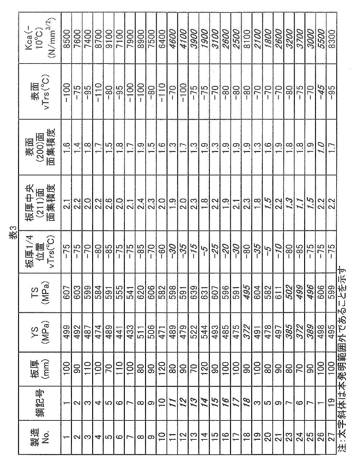
- Molten steel (steel symbols: 1 to 19) with each component composition shown in Table 1 is melted in a converter and made into a steel material by a continuous casting method. After hot rolling to a plate thickness of 70 to 120 mm, cooling is performed and No. . Sample steels of 1 to 27 were obtained. Table 2 shows heating conditions, hot rolling conditions and cooling conditions. Moreover, the tempering temperature was also shown about what tempered.
- a ⁇ 14 JIS No. 14A test piece was sampled from the position of the plate thickness 1 ⁇ 4, a tensile test was performed, and a yield strength (YS) and a tensile strength (TS) were measured.
- YS yield strength
- TS tensile strength
- a JIS No. 4 impact test piece was taken from the 1/4 position of the plate thickness and the surface of the steel plate so that the longitudinal axis direction of the test piece was parallel to the rolling direction, and a Charpy impact test was conducted to determine the fracture surface transition temperature (vTrs ) The case where the vTrs at the 1/4 position was ⁇ 40 ° C. or lower and the surface vTrs was ⁇ 60 ° C. or lower was considered good.
- the (211) plane integration degree on the rolled surface at the center of the plate thickness and the (200) plane integration degree on the steel sheet surface were measured.
- the degree of surface integration was measured using an X-ray diffractometer (manufactured by Rigaku Corporation) and using a Mo ray source.
- Kca ( ⁇ 10 ° C.) N / mm 3/2 a temperature gradient type ESSO test was performed to obtain a Kca value at -10 ° C. (hereinafter also referred to as Kca ( ⁇ 10 ° C.) N / mm 3/2 ).
- Kca ( ⁇ 10 ° C.) N / mm 3/2 A material having a Kca ( ⁇ 10 ° C.) of 6000 N / mm 3/2 or more was considered good.
Landscapes
- Chemical & Material Sciences (AREA)
- Engineering & Computer Science (AREA)
- Mechanical Engineering (AREA)
- Materials Engineering (AREA)
- Metallurgy (AREA)
- Organic Chemistry (AREA)
- Physics & Mathematics (AREA)
- Thermal Sciences (AREA)
- Crystallography & Structural Chemistry (AREA)
- Heat Treatment Of Steel (AREA)
Abstract
Description
(a)微細なフェライト結晶粒を確保する圧延条件、
(b)鋼板板厚の5%以上の部分に微細フェライト組織を生成する圧延条件、
(c)微細フェライトに集合組織を発達させるとともに加工(圧延)により導入した転位を熱的エネルギーにより再配置しサブグレインを形成させる圧延条件、および
(d)形成した微細なフェライト結晶粒と微細なサブグレイン粒の粗大化を抑制する冷却条件、
によって脆性き裂伝播停止特性を向上させる技術が記載されている。
Ceq=C+Mn/6+Cu/15+Ni/15+Cr/5+Mo/5+V/5 (1)
(ここで、式(1)におけるC、Mn、Cu、Ni、Cr、MoおよびVは各元素の含有量(質量%)を意味し、含有しない場合は0とする。)
[2]前記成分組成は、さらに質量%で、Nb:0.005~0.05%、Cu:0.1~1.0%およびCr:0.01~0.5%の1種または2種以上を含有する[1]に記載の脆性き裂伝播停止特性に優れた高強度極厚鋼板。
本発明の高強度極厚鋼板は、質量%で、C:0.03~0.20%、Si:0.03~0.5%、Mn:0.5~2.2%、P:0.01%以下、S:0.005%以下、Ti:0.005~0.03%、Al:0.005~0.080%、Ni:0.1~1.5%およびN:0.0050%以下を含有し、下記式(1)で定義されるCeq:0.39以上である。
Ceq=C+Mn/6+Cu/15+Ni/15+Cr/5+Mo/5+V/5 (1)
ここで、式(1)における元素記号は各元素の含有量(質量%)を意味し、含有しない場合は0とする。
Cは、鋼の強度を向上させる元素である。本発明では、所望の強度を確保するために、C含有量を0.03%以上とする。また、C含有量が0.20%を超えると、溶接性が劣化するばかりか靭性にも悪影響がある。このため、C含有量は、0.03~0.20%の範囲とする。なお、下限について好ましいC含有量は0.05%以上であり、上限について好ましいC含有量は0.15%以下である。
Siは、脱酸元素として、また、鋼の強化元素として有効である。Si含有量が0.03%未満ではこれらの効果が得られない。一方、Si含有量が0.5%を超えると鋼の表面性状を損なうばかりか、靭性が極端に劣化する。従って、その含有量を0.03~0.5%の範囲とする。
Mnは、強化元素として含まれる。Mn含有量が0.5%より少ないとその効果が十分でない一方で、2.2%を超えると溶接性が劣化し、鋼板コストも上昇する。そのため、Mn含有量は、0.5~2.2%とする。
P、Sは、鋼中の不可避的不純物である。これらの含有量が多くなると靭性が劣化する。板厚:70mm以上の鋼板において、良好な靭性を保つためには、P含有量は0.01%以下、S含有量は0.005%以下に抑制する。なお、それぞれ0.006%以下、0.003%以下がより望ましい範囲である。
Tiは、微量の含有により、窒化物、炭化物、あるいは炭窒化物を形成し、結晶粒を微細化して母材靭性を向上させる効果を有する。その効果はTi含有量を0.005%以上にすることによって得られる。また、Ti含有量が0.03%を超えると、母材および溶接熱影響部の靭性が低下する。そこで、Ti含有量は0.005~0.03%とする。
Alは、脱酸剤として作用し、Alを脱酸剤として用いるためにはAl含有量を0.005%以上にする必要がある。また、Al含有量が0.080%を超えると、靭性が低下するとともに、溶接した場合に、溶接金属部の靭性が低下する。このため、Al含有量は、0.005~0.080%の範囲に規定した。なお、下限について好ましいAl含有量は、0.020以上であり、上限について好ましいAl含有量は0.040%以下である。
Niは、鋼の焼入れ性を高める元素である。Niは、圧延後の強度向上に直接寄与するとともに、靭性、高温強度、あるいは耐候性などの機能向上のために含有させることができる。これらの効果は、いずれも、Ni含有量を0.1%以上にすることよって発揮される。また、過度のNi含有は靭性や溶接性を劣化させる。板厚:70mm以上の鋼板で十分な強度を保ちつつ靭性や溶接性を劣化させない範囲として、Ni含有量は0.1~1.5%とする。
Nは、鋼中のAlと結合し、圧延加工時の結晶粒径を調整し、鋼を強化する。この効果を得るためにはN含有量を0.0010%以上にすることが好ましい。また、N含有量が0.0050%を超えると靭性が劣化する。そこで、N含有量は0.0050%以下とする。
Nbは、NbCとしてフェライト変態時あるいは再加熱時に析出し、高強度化に寄与する。また、Nbはオーステナイト域の圧延において未再結晶域を拡大させる効果を有し、フェライトの細粒化に寄与する。このためNb含有は靭性の改善にも有効である。その効果はNb含有量を0.005%以上にすることで発揮される。Nb含有量が0.05%を超えると、粗大なNbCが析出して、靭性の低下を招く場合がある。そこで、Nbを含有する場合、その含有量を0.05%以下とするのが好ましい。
Cuは、鋼の焼入れ性を高める元素である。この元素は、圧延後の強度向上に直接寄与するとともに、靭性、高温強度、あるいは耐候性などの機能向上のために含有させることができる。この元素含有による上記効果は、0.1%以上の含有によって発揮されるものの、過度の含有は靭性や溶接性を劣化させる。板厚:70mm以上でも十分な強度を保ちつつ靭性や溶接性を劣化させない範囲として、Cu含有量は0.1~1.0%とすることが好ましい。
Crは、鋼の焼入れ性を高める元素である。この元素は、圧延後の強度向上に直接寄与するとともに、靭性、高温強度、あるいは耐候性などの機能向上のために含有させることができる。この元素含有による上記効果は、0.01%以上の含有によって発揮されるものの、過度の含有は靭性や溶接性を劣化させる。板厚:70mm以上でも十分な強度を保ちつつ靭性や溶接性を劣化させない範囲として、Cr含有量は0.01~0.5%とすることが好ましい。
Moは、いずれも鋼の焼入れ性を高める元素である。この元素は、圧延後の強度向上に直接寄与するとともに、靭性、高温強度、あるいは耐候性などの機能向上のために含有させることができる。上記効果は、0.01%以上の含有によって発揮されるものの、過度の含有は靭性や溶接性を劣化させる。板厚:70mm以上でも十分な強度を保ちつつ靭性や溶接性を劣化させない範囲として、Mo含有量は0.01~0.5%とすることが好ましい。
Vは、V(CN)として析出する析出強化によって、鋼の強度を向上させる元素である。この効果は、V含有量を0.001%以上にすることにより発揮される。しかし、V含有量が0.10%を超えると、靭性が低下する場合がある。このため、Vを含有させる場合には、V含有量を0.001~0.10%の範囲とすることが好ましい。
Bは、鋼の焼入れ性を高める元素であり、B含有量が0.0030%以下のような微量でも上記効果が得られる。また、B含有量が0.0030%を超えると溶接部の靭性が低下するので、Bを含有させる場合には、B含有量は0.0030%以下とすることが好ましい。なお、上記効果を得る観点からは、B含有量の下限は0.0006%とすることが好ましい。
Ca、REMは、溶接熱影響部の組織を微細化し靭性を向上させる。これらの成分を含有しても本発明の効果が損なわれることはないので必要に応じて含有してもよい。しかし、過度に含有すると、粗大な介在物を形成し母材の靭性を劣化させる場合がある。そこで、これらの成分を含有させる場合には、含有量の上限をそれぞれ0.0050%、0.0100%とするのが好ましい。
本発明に係る高強度極厚鋼板では、上記各成分が上記含有量の範囲にあることに加えて、下記式(1)で表すCeqを0.39以上に調整する。Ceq<0.39であると、板厚中央における圧延面での(211)面集積度を高くし難くなる。また、Ceqの上限は特に限定されないが溶接性を確保するため、Ceqは0.51以下であることが好ましい。
Ceq=C+Mn/6+Cu/15+Ni/15+Cr/5+Mo/5+V/5 (1)
ここで、式(1)におけるC、Mn、Cu、Ni、Cr、MoおよびVは各元素の含有量(質量%)を意味し、含有しない場合は0とする。
本発明の高強度極厚鋼板は、板厚中央における圧延面での(211)面集積度が1.7以上、表面(極表面から表面下1mmの範囲)における圧延面での(200)面集積度が1.3以上を満たす集合組織を有する。上記の成分組成を採用するとともに、後述する製造条件で集合組織が上記範囲を満たすように制御することで、脆性き裂伝播停止特性に優れた高強度極厚鋼板が得られる。
本発明では、板厚1/4位置から採取したJIS 4号の衝撃試験片を用いて測定した靭性がvTrs:-40℃以下であり、表面から採取したJIS 4号の衝撃試験片を用いて測定した靭性がvTrs≦-60℃である。特定の位置の靭性が上記範囲にあることで、脆性き裂伝播停止特性が改善する。
上記成分組成の溶鋼を、転炉等で溶製し、連続鋳造等で鋼素材(スラブ)とし、1000~1200℃に加熱後、熱間圧延を行う。


Claims (4)
- 板厚:70mm以上の高強度極厚鋼板であって、
質量%で、C:0.03~0.20%、Si:0.03~0.5%、Mn:0.5~2.2%、P:0.01%以下、S:0.005%以下、Ti:0.005~0.03%、Al:0.005~0.080%、Ni:0.1~1.5%およびN:0.0050%以下を含有し、下記式(1)で定義されるCeq:0.39以上であり、残部がFeおよび不可避的不純物からなる成分組成と、
板厚中央における圧延面での(211)面集積度が1.7以上であり、鋼板表面での(200)面集積度が1.3以上である集合組織と、を有し、
板厚1/4位置から採取したJIS 4号の衝撃試験片を用いて測定した靭性がvTrs:-40℃以下であり、
表面から採取したJIS 4号の衝撃試験片を用いて測定した靭性がvTrs≦-60℃である高強度極厚鋼板。
Ceq=C+Mn/6+Cu/15+Ni/15+Cr/5+Mo/5+V/5 (1)
(ここで、式(1)におけるC、Mn、Cu、Ni、Cr、MoおよびVは各元素の含有量(質量%)を意味し、含有しない場合は0とする。) - 前記成分組成は、さらに質量%で、Nb:0.005~0.05%、Cu:0.1~1.0%およびCr:0.01~0.5%の1種または2種以上を含有する請求項1に記載の高強度極厚鋼板。
- 前記成分組成は、さらに質量%で、Mo:0.01~0.5%、V:0.001~0.10%、B:0.0030%以下、Ca:0.0050%以下、REM:0.0100%以下の1種または2種以上を含有する請求項1または2に記載の高強度極厚鋼板。
- 板厚:70mm以上の脆性き裂伝播停止特性に優れた高強度極厚鋼板の製造方法であって、
請求項1~3のいずれかに記載の成分組成を有する鋼素材を、1000~1200℃の温度に加熱した後、
板厚中央がオーステナイト再結晶温度域のときの累積圧下率:10%以上、板厚中央がオーステナイト未再結晶温度域のときの累積圧下率:50%以上、表面がAr3温度以下かつ板厚中央温度がAr3温度以上の温度域のときの累積圧下率10%以上の条件で熱間圧延を行った後、
0.5℃/s以上の冷却速度にて500℃以下の冷却停止温度まで冷却するか、又は0.5℃/s以上の冷却速度にて400℃以下の冷却停止温度まで冷却して冷却後Ac1点以下の温度に焼戻す高強度極厚鋼板の製造方法。
Priority Applications (3)
| Application Number | Priority Date | Filing Date | Title |
|---|---|---|---|
| CN201680010045.4A CN107208238B (zh) | 2015-03-12 | 2016-03-09 | 高强度极厚钢板及其制造方法 |
| KR1020177017113A KR101964247B1 (ko) | 2015-03-12 | 2016-03-09 | 고강도 극후 강판 및 그의 제조 방법 |
| JP2016553622A JP6112265B2 (ja) | 2015-03-12 | 2016-03-09 | 高強度極厚鋼板およびその製造方法 |
Applications Claiming Priority (2)
| Application Number | Priority Date | Filing Date | Title |
|---|---|---|---|
| JP2015-049371 | 2015-03-12 | ||
| JP2015049371 | 2015-03-12 |
Publications (1)
| Publication Number | Publication Date |
|---|---|
| WO2016143345A1 true WO2016143345A1 (ja) | 2016-09-15 |
Family
ID=56880396
Family Applications (1)
| Application Number | Title | Priority Date | Filing Date |
|---|---|---|---|
| PCT/JP2016/001311 Ceased WO2016143345A1 (ja) | 2015-03-12 | 2016-03-09 | 高強度極厚鋼板およびその製造方法 |
Country Status (5)
| Country | Link |
|---|---|
| JP (1) | JP6112265B2 (ja) |
| KR (1) | KR101964247B1 (ja) |
| CN (1) | CN107208238B (ja) |
| TW (1) | TWI582245B (ja) |
| WO (1) | WO2016143345A1 (ja) |
Cited By (4)
| Publication number | Priority date | Publication date | Assignee | Title |
|---|---|---|---|---|
| WO2017145651A1 (ja) * | 2016-02-24 | 2017-08-31 | Jfeスチール株式会社 | 脆性き裂伝播停止特性に優れた高強度極厚鋼板およびその製造方法 |
| JP2020509168A (ja) * | 2016-12-22 | 2020-03-26 | ポスコPosco | 表面部nrl−落重試験物性に優れた極厚鋼材及びその製造方法 |
| JP2024066169A (ja) * | 2022-11-01 | 2024-05-15 | Jfeスチール株式会社 | 重ね圧延鋼板およびその製造方法 |
| JP2024066170A (ja) * | 2022-11-01 | 2024-05-15 | Jfeスチール株式会社 | 重ね圧延鋼板およびその製造方法 |
Families Citing this family (1)
| Publication number | Priority date | Publication date | Assignee | Title |
|---|---|---|---|---|
| KR102326109B1 (ko) * | 2019-12-16 | 2021-11-16 | 주식회사 포스코 | 황화물 응력부식 균열 저항성이 우수한 강재 및 이의 제조방법 |
Citations (4)
| Publication number | Priority date | Publication date | Assignee | Title |
|---|---|---|---|---|
| JP2008169468A (ja) * | 2006-12-14 | 2008-07-24 | Nippon Steel Corp | 脆性き裂伝播停止性能に優れた高強度厚鋼板 |
| JP2008214652A (ja) * | 2007-02-28 | 2008-09-18 | Jfe Steel Kk | 脆性亀裂伝播停止特性に優れた構造用高強度厚鋼板およびその製造方法 |
| JP2010047805A (ja) * | 2008-08-22 | 2010-03-04 | Jfe Steel Corp | 大入熱溶接部の靭性および脆性き裂伝播停止特性に優れた高強度厚鋼板およびその製造方法 |
| WO2013099319A1 (ja) * | 2011-12-27 | 2013-07-04 | Jfeスチール株式会社 | 脆性亀裂伝播停止特性に優れた構造用高強度厚鋼板およびその製造方法 |
Family Cites Families (7)
| Publication number | Priority date | Publication date | Assignee | Title |
|---|---|---|---|---|
| JPS548349A (en) | 1977-06-22 | 1979-01-22 | Mitsubishi Electric Corp | Elevator door device |
| JP2659661B2 (ja) | 1993-01-06 | 1997-09-30 | 新日本製鐵株式会社 | 継手部の脆性破壊伝播停止性能の優れた溶接用構造用鋼とその製造方法 |
| JPH07100814A (ja) | 1993-10-04 | 1995-04-18 | Sekisui Chem Co Ltd | セメント成形品の製造方法 |
| JP3467767B2 (ja) | 1998-03-13 | 2003-11-17 | Jfeスチール株式会社 | 脆性亀裂伝播停止特性に優れた鋼材およびその製造方法 |
| JP4077167B2 (ja) | 2001-02-28 | 2008-04-16 | 株式会社神戸製鋼所 | アレスト特性に優れた鋼板およびその製法 |
| JP5598485B2 (ja) * | 2011-02-08 | 2014-10-01 | Jfeスチール株式会社 | 長大脆性き裂伝播停止特性に優れる板厚50mm以上の厚鋼板およびその製造方法 |
| WO2014155439A1 (ja) * | 2013-03-26 | 2014-10-02 | Jfeスチール株式会社 | 脆性亀裂伝播停止特性に優れた大入熱溶接用高強度鋼板およびその製造方法 |
-
2016
- 2016-03-09 JP JP2016553622A patent/JP6112265B2/ja active Active
- 2016-03-09 KR KR1020177017113A patent/KR101964247B1/ko active Active
- 2016-03-09 CN CN201680010045.4A patent/CN107208238B/zh active Active
- 2016-03-09 WO PCT/JP2016/001311 patent/WO2016143345A1/ja not_active Ceased
- 2016-03-11 TW TW105107530A patent/TWI582245B/zh active
Patent Citations (4)
| Publication number | Priority date | Publication date | Assignee | Title |
|---|---|---|---|---|
| JP2008169468A (ja) * | 2006-12-14 | 2008-07-24 | Nippon Steel Corp | 脆性き裂伝播停止性能に優れた高強度厚鋼板 |
| JP2008214652A (ja) * | 2007-02-28 | 2008-09-18 | Jfe Steel Kk | 脆性亀裂伝播停止特性に優れた構造用高強度厚鋼板およびその製造方法 |
| JP2010047805A (ja) * | 2008-08-22 | 2010-03-04 | Jfe Steel Corp | 大入熱溶接部の靭性および脆性き裂伝播停止特性に優れた高強度厚鋼板およびその製造方法 |
| WO2013099319A1 (ja) * | 2011-12-27 | 2013-07-04 | Jfeスチール株式会社 | 脆性亀裂伝播停止特性に優れた構造用高強度厚鋼板およびその製造方法 |
Cited By (7)
| Publication number | Priority date | Publication date | Assignee | Title |
|---|---|---|---|---|
| WO2017145651A1 (ja) * | 2016-02-24 | 2017-08-31 | Jfeスチール株式会社 | 脆性き裂伝播停止特性に優れた高強度極厚鋼板およびその製造方法 |
| JP2020509168A (ja) * | 2016-12-22 | 2020-03-26 | ポスコPosco | 表面部nrl−落重試験物性に優れた極厚鋼材及びその製造方法 |
| US11634784B2 (en) | 2016-12-22 | 2023-04-25 | Posco Co., Ltd | Ultra-thick steel material having excellent surface part NRL-DWT properties and method for manufacturing same |
| JP2024066169A (ja) * | 2022-11-01 | 2024-05-15 | Jfeスチール株式会社 | 重ね圧延鋼板およびその製造方法 |
| JP2024066170A (ja) * | 2022-11-01 | 2024-05-15 | Jfeスチール株式会社 | 重ね圧延鋼板およびその製造方法 |
| JP7726183B2 (ja) | 2022-11-01 | 2025-08-20 | Jfeスチール株式会社 | 重ね圧延鋼板およびその製造方法 |
| JP7726184B2 (ja) | 2022-11-01 | 2025-08-20 | Jfeスチール株式会社 | 重ね圧延鋼板およびその製造方法 |
Also Published As
| Publication number | Publication date |
|---|---|
| JPWO2016143345A1 (ja) | 2017-04-27 |
| TW201641713A (zh) | 2016-12-01 |
| CN107208238B (zh) | 2018-11-23 |
| KR101964247B1 (ko) | 2019-04-01 |
| JP6112265B2 (ja) | 2017-04-12 |
| CN107208238A (zh) | 2017-09-26 |
| KR20170086102A (ko) | 2017-07-25 |
| TWI582245B (zh) | 2017-05-11 |
Similar Documents
| Publication | Publication Date | Title |
|---|---|---|
| JP5304925B2 (ja) | 脆性亀裂伝播停止特性に優れた構造用高強度厚鋼板およびその製造方法 | |
| JP5733425B2 (ja) | 脆性き裂伝播停止特性に優れた高強度厚鋼板およびその製造方法 | |
| JP5434145B2 (ja) | 脆性亀裂伝播停止特性に優れた構造用高強度厚鋼板およびその製造方法 | |
| JP6536514B2 (ja) | 脆性亀裂伝播停止特性に優れた構造用高強度厚鋼板およびその製造方法 | |
| CN108291287B (zh) | 具有优异的止脆裂性和焊接部分脆裂萌生抗力的高强度钢及其生产方法 | |
| JP5304924B2 (ja) | 脆性亀裂伝播停止特性に優れた構造用高強度厚鋼板およびその製造方法 | |
| JP6112265B2 (ja) | 高強度極厚鋼板およびその製造方法 | |
| JP5035199B2 (ja) | 脆性亀裂伝播停止特性に優れた構造用高強度厚鋼板およびその製造方法 | |
| JP5812193B2 (ja) | 脆性き裂伝播停止特性に優れた構造用高強度厚鋼板およびその製造方法 | |
| JP5949113B2 (ja) | 脆性き裂伝播停止特性に優れた構造用高強度厚鋼板およびその製造方法 | |
| CN104024456B (zh) | 脆性裂纹传播停止特性优良的结构用高强度厚钢板及其制造方法 | |
| JP6477743B2 (ja) | 脆性き裂伝播停止特性および溶接熱影響部靭性に優れた高強度極厚鋼板およびその製造方法 | |
| JP6338022B2 (ja) | 脆性き裂伝播停止特性に優れた高強度極厚鋼板およびその製造方法 | |
| WO2018030186A1 (ja) | 高強度厚鋼板およびその製造方法 | |
| JP5838801B2 (ja) | 厚鋼板及び厚鋼板の製造方法 | |
| JP5949114B2 (ja) | 脆性き裂伝播停止特性に優れた構造用高強度厚鋼板の製造方法 |
Legal Events
| Date | Code | Title | Description |
|---|---|---|---|
| ENP | Entry into the national phase |
Ref document number: 2016553622 Country of ref document: JP Kind code of ref document: A |
|
| 121 | Ep: the epo has been informed by wipo that ep was designated in this application |
Ref document number: 16761318 Country of ref document: EP Kind code of ref document: A1 |
|
| ENP | Entry into the national phase |
Ref document number: 20177017113 Country of ref document: KR Kind code of ref document: A |
|
| NENP | Non-entry into the national phase |
Ref country code: DE |
|
| 122 | Ep: pct application non-entry in european phase |
Ref document number: 16761318 Country of ref document: EP Kind code of ref document: A1 |