WO2016142980A1 - Optical amplification device and light source device - Google Patents
Optical amplification device and light source device Download PDFInfo
- Publication number
- WO2016142980A1 WO2016142980A1 PCT/JP2015/006443 JP2015006443W WO2016142980A1 WO 2016142980 A1 WO2016142980 A1 WO 2016142980A1 JP 2015006443 W JP2015006443 W JP 2015006443W WO 2016142980 A1 WO2016142980 A1 WO 2016142980A1
- Authority
- WO
- WIPO (PCT)
- Prior art keywords
- optical
- unit
- laser light
- incident
- laser beam
- Prior art date
Links
Images


Classifications
-
- H—ELECTRICITY
- H01—ELECTRIC ELEMENTS
- H01S—DEVICES USING THE PROCESS OF LIGHT AMPLIFICATION BY STIMULATED EMISSION OF RADIATION [LASER] TO AMPLIFY OR GENERATE LIGHT; DEVICES USING STIMULATED EMISSION OF ELECTROMAGNETIC RADIATION IN WAVE RANGES OTHER THAN OPTICAL
- H01S5/00—Semiconductor lasers
- H01S5/50—Amplifier structures not provided for in groups H01S5/02 - H01S5/30
Definitions
- the present technology relates to an optical amplification device and a light source device using the same.
- Patent Document 1 includes a MOPA (Master Oscillator Power Amplifier) type light source that combines MLLD (Mode Locked Laser Diode) and SOA (Semiconductor Optical Amp) as a recording light source.
- MOPA Master Oscillator Power Amplifier
- MLLD Mode Locked Laser Diode
- SOA semiconductor Optical Amp
- An optical recording system is described.
- an isolator based on a combination of a quarter wavelength plate and a polarization beam splitter is disposed between the MLLD unit and the SOA. With this isolator, unnecessary return light (self-incident component) generated from the incident end of the SOA and returning to the SOA again by reflection or the like is removed (paragraphs [0006] and [0044] in the specification of Patent Document 1) ).
- Patent Document 2 describes a laser device for an LPP (Laser Produced Plasma) type EUV (Extreme Ultraviolet) light generation device.
- the laser apparatus includes a master oscillator (MO), a plurality of amplifiers (PA), and a plurality of Faraday isolators.
- Faraday isolators are arranged so as to sandwich each amplifier.
- optical amplification device it is required to prevent unnecessary return light from entering.
- optical isolators before and after the SOA or the like, but when two expensive optical isolators are used, the apparatus becomes expensive and difficult to downsize.
- an object of the present technology is to provide an optical amplifying device that can prevent the return light from entering the optical amplifying element, and that can be reduced in size and cost, and a light source using the same. To provide an apparatus.
- an optical amplification device includes a conversion unit, a first optical element, a second optical element, and an optical amplification unit.
- the conversion unit includes a Faraday rotator capable of converting a polarization state of laser light.
- the first optical element has a first incident port and a second incident port that is different from the first incident port, and is a laser in a first polarization state that is incident on the first incident port.
- the first laser beam, which is light, and the second laser beam, which is a laser beam having a second polarization state different from the first polarization state incident on the second incident port, are directed to the conversion unit. Respectively.
- the second optical element can emit the first laser light whose polarization state is converted by the conversion unit as laser light of the second polarization state, and the polarization state is converted by the conversion unit.
- the second laser beam can be emitted toward the output unit to the outside.
- the optical amplification unit includes an optical amplification element that amplifies the first laser light emitted as the laser light in the second polarization state by the second optical element, and the amplified first Laser light is incident on the second incident port of the first optical element as the second laser light.
- the first laser light incident on the first optical element is amplified and again incident on the first optical element as the second laser light.
- the second laser light is emitted to the output unit to the outside through the first optical element, the conversion unit, and the second optical element.
- the conversion unit may include a conversion element that converts the first laser light whose polarization state is converted by the Faraday rotator into laser light of the second polarization state.
- the second optical element may emit the first laser light converted into the laser light in the second polarization state by the conversion element. Since the polarization state of the first laser light is converted to the second polarization state by the conversion unit, the arrangement configuration of the second optical element can be simplified.
- the second optical element may convert the first laser beam, the polarization state of which has been converted by the Faraday rotator, into a laser beam having the second polarization state, and emit the laser beam.
- the configuration of the conversion unit can be simplified, and the size of the apparatus can be reduced.
- the conversion element may be a crystal rotator, which is an optical crystal having optical activity, or a half-wave plate. By using these members as the conversion element, the conversion unit can be easily realized.
- the optical amplification element may include an incident portion on which the first laser light emitted from the second optical element is incident, and an emission portion from which the amplified first laser light is emitted.
- the light amplifying unit is disposed between the second optical element and the incident unit, and the first filter unit restricts the first unnecessary light traveling from the second optical element to the incident unit.
- a second filter unit that is disposed between the first optical element and the emission unit and restricts second unnecessary light that travels from the first optical element to the emission unit.
- the conversion element may be a crystal rotator which is an optical crystal having optical activity.
- the optical amplification unit includes a separation unit capable of separating the first laser light emitted from the second optical element into a plurality of separated laser beams for each wavelength, and the plurality of separated separation lasers.
- You may have a some optical amplification element which amplifies each of light, and the synthetic
- the optical amplification unit is disposed between the second optical element and the separation unit, and includes a first filter unit that regulates first unnecessary light that travels from the second optical element to the separation unit, and the first filter unit. And a second filter unit that is disposed between the first optical element and the combining unit and restricts second unnecessary light that travels from the first optical element to the combining unit. Thereby, it is possible to sufficiently prevent the unnecessary light from entering the plurality of optical amplifying elements.
- the first filter unit may spatially filter the first unnecessary light.
- the second filter unit may spatially filter the second unnecessary light.
- the first optical element transmits the first laser light incident on the first incident port onto a predetermined optical path toward the conversion unit, and enters the second incident port.
- the laser beam may be reflected toward the conversion unit so as to travel obliquely at a predetermined angle from the predetermined optical path.
- the predetermined angle may be included in a range of not less than ⁇ 2 degrees and not more than +2 degrees. Thereby, amplification of laser light and regulation of unnecessary light are realized with high accuracy.
- the first optical element may emit a pulse laser beam incident on the first incident port toward the conversion unit as the first laser beam.
- the optical amplifying element has an incident part on which the first laser light emitted from the second optical element is incident, and an emitting part from which the amplified first laser light is emitted. May be.
- the optical amplifying unit is configured so that an optical path length of a circulating optical path from the emitting unit to the incident unit through the first optical element, the converting unit, and the second optical element is the optical path length.
- the value divided by the speed may be set to be different from a value that is an integral multiple of the pulse period of the pulse laser beam.
- the incident timing and the optical amplification operation timing by the optical amplifying element can be shifted. As a result, it is possible to sufficiently suppress the influence due to the incidence of unnecessary light.
- a light source device includes a light source unit, a conversion unit, a first optical element, a second optical element, and an optical amplification unit.
- the light source unit emits laser light.
- the conversion unit includes a Faraday rotator capable of converting a polarization state of laser light.
- the first optical element has a first incident port and a second incident port different from the first incident port, and is emitted from the light source unit toward the first incident port.
- a first laser beam, which is a laser beam in a first polarization state, and a second laser beam, which is a laser beam in a second polarization state different from the first polarization state incident on the second incident port. Are respectively emitted toward the converter.
- the second optical element can emit the first laser light whose polarization state is converted by the conversion unit as laser light of the second polarization state, and the polarization state is converted by the conversion unit.
- the second laser beam can be emitted toward the output unit to the outside.
- the optical amplification unit includes an optical amplification element that amplifies the first laser light emitted as the laser light in the second polarization state by the second optical element, and the amplified first Laser light is incident on the second incident port of the first optical element as the second laser light.
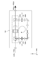
- FIG. 1 is a block diagram schematically illustrating a configuration example of a microscope system according to the first embodiment of the present technology.
- the microscope system 1000 for example, a laser scanning microscope for biological analysis is used.
- the present technology can also be applied to various microscopes used for other purposes.
- the microscope system 1000 includes a microscope main body 10, a control unit 20, and a light source device 30 according to the present technology.
- the microscope main body 10 spot-condenses the laser light emitted from the light source device 30 on a sample (sample), and scans this in three dimensions.
- the enlarged image of the sample obtained by the scanning is digitized, and a sample image data group is generated.
- the microscope main body 10 includes, for example, a stage on which a sample is placed, a scanning optical system that scans laser light, a magnifying optical system that generates an enlarged image of the sample, a digital camera, and the like (all not shown).
- a specific configuration of the microscope main body 10, a method of scanning with laser light, and the like are not limited.
- the control unit 20 controls the operations of the microscope main body 10 and the light source device 30.
- the specific configuration of the control unit 20 is not limited, and a known technique may be used as appropriate.
- the light source device 30 includes a laser light source unit 40, two ISO units (optical isolator units) 50, an SOA unit 60, a wavelength conversion unit 70, and the optical amplification device 100 according to the present embodiment.
- the laser light source unit 40 emits laser light.
- the laser light source unit 40 for example, an MLLD that emits pulsed laser light or the like is used.
- various laser light sources such as a laser light source that emits continuous laser light may be used.
- the SOA unit 60 has an SOA (not shown).
- the SOA amplifies the laser light emitted from the laser light source unit 40 in accordance with the applied control current.
- the ISO unit 50 is arranged at the front stage and the rear stage of the SOA unit 60.
- the ISO unit 50 allows only passage of laser light in the forward direction. These two ISO parts 50 prevent unnecessary return light from entering the SOA of the SOA part 60.
- the wavelength conversion unit 70 converts the wavelength of the laser light amplified by the SOA unit 50.
- a wavelength conversion module (Optical Parametric Oscillation: OPO) having LBO is used.
- OPO Optical Parametric Oscillation
- Other wavelength conversion modules may be used.
- the light source device 30 when used as a light source for two-photon excitation, laser light having a wavelength of about 405 nm is emitted from the laser light source unit 40. Then, the wavelength conversion unit 70 converts the wavelength to a wavelength (about 900 nm to 1300 nm) that produces a two-photon effect at a high density.
- the wavelength of the laser light emitted from the laser light source unit 40, the range of convertible wavelengths, and the like are not limited.
- the optical amplification device 100 amplifies the laser light whose wavelength is converted by the wavelength conversion unit 70.
- the light source device including the laser light source unit 40 and the optical amplification device 100 described below is not limited to the configuration illustrated in FIG. 1 and can be implemented as a light source device according to the present technology.
- FIG. 2 is a schematic diagram illustrating a configuration example of the optical amplifying device according to the present embodiment.
- terms such as a front stage, a rear stage, a downstream side, and an upstream side are used with reference to the traveling direction of the laser light that travels in the optical amplifying apparatus 100. That is, the side on which the laser light is incident is the front stage and the upstream side, and the side from which the laser light is emitted is the rear stage and the downstream side.
- the optical amplification apparatus 100 includes an input unit 101 to which an input laser beam I is input, an isolator unit 102, an optical amplification unit 103, and an output unit 104 that outputs the amplified laser beam to the outside.
- the laser beam output from the output unit 104 becomes the output laser beam O.
- the isolator unit 102 receives an input laser beam I input from the input unit 101.
- the isolator unit 102 includes a first PBS (polarizing beam splitter) 105, a Faraday rotator 106, a crystal rotator 107, and a second PBS 108, which are arranged substantially linearly in the x direction in the figure. These members are arranged in this order from upstream to downstream.
- the linear optical path from the first PBS 105 to the second PBS 108 is referred to as a linear optical path P1.
- the first PBS 105 transmits P-polarized light to the separation surface 105a and reflects S-polarized light. As shown in FIG. 2, the first incident surface 105b of the first PBS 105 is arranged in a direction orthogonal to the x direction, and the P-polarized light incident on the first incident surface 105b is transmitted as it is onto the linear optical path P1. Is done.
- the surface that is in a direction different from the first incident surface 105 b and that is orthogonal to the y direction in the figure is the second incident surface 105 c of the first PBS 105. S-polarized light incident on the second incident surface 105c along the y direction is reflected on the linear optical path P1.
- the first PBS 105 corresponds to the first optical element in the present embodiment.
- the P-polarized light incident on the first emission surface 105b corresponds to the first laser light L1 that is the laser light in the first polarization state incident on the first incident port.
- the S-polarized light incident on the second emission surface 105c corresponds to the second laser light L2 that is the laser light in the second polarization state incident on the second incident port.
- the input laser beam I is incident on the first incident surface 105b as the first laser beam L1. Further, laser light having the same polarization state as the P-polarized light and S-polarized light with respect to the separation surface 105a of the first PBS 105 will be described as P-polarized light and S-polarized light as they are.
- the Faraday rotator 106 is a magnetic optical crystal, and rotates the polarization direction of the laser light emitted from the first PBS 105 by 45 degrees when a magnetic field is applied.
- the crystal rotator 107 is an optical crystal having natural optical rotation such as quartz or quartz, and rotates the polarization direction of the laser light emitted from the Faraday rotator by 45 degrees in the same direction. Therefore, the polarization direction of the laser light passing through the Faraday rotator 106 and the crystal rotator 107 from the upstream side is rotated by 90 degrees. That is, P-polarized light is converted to S-polarized light, and S-polarized light is converted to P-polarized light.
- the Faraday rotator 106 and the crystal rotator 107 constitute the conversion unit 110 according to this embodiment.
- the crystal rotator 107 corresponds to a conversion element that converts the first laser light L1 whose polarization state has been converted by the Faraday rotator 106 into S-polarized light.
- the rotation of the polarization direction corresponds to the conversion of the polarization state.
- the conversion unit 110 can be realized with a simple configuration.
- the second PBS 108 reflects the first laser light L1 whose polarization state has been converted by the conversion unit 110 to become S-polarized light along a predetermined direction (y direction in the drawing). In addition, the second PBS 108 transmits the second laser light L ⁇ b> 2 whose polarization state has been converted by the conversion unit 110 into P-polarized light toward the output unit 104.
- the second PBS 108 corresponds to a second optical element in the present embodiment.
- Specific configurations of the first PBS 105, the Faraday rotator 106, the crystal rotator 107, the half-wave plate, and the second PBS 108 are not limited, and other optical elements having the same function may be used. .
- a crystalline polarization separation element such as a Glan-Thompson prism may be used instead of PBS.
- the method of emitting laser light to a member or the like in the subsequent stage is not limited, and transmission, reflection, or the like may be appropriately performed.
- the optical amplifying unit 103 amplifies the first laser light L1 reflected by the second PBS 108 and makes it incident on the second incident surface 105 c of the first PBS 105.
- the first laser beam L1 is converted to S-polarized light. Accordingly, when viewed from the first PBS 105, the first laser light L1 is incident as the second laser light L2.
- the optical amplification unit 103 includes a first filter unit 111, a first mirror 112, a first lens 113, an SOA 114 as an optical amplification element, a second lens 115, and a second lens 115. 2 mirrors 116 and a second filter unit 117.
- the first mirror 112 reflects the first laser light L 1 that has passed through the first filter unit 111 toward the first lens 113.
- the first lens 113 condenses the first laser light L1 on the incident end (incident part) 114a of the SOA 114.
- the SOA 114 amplifies the first laser beam L1 by current injection from the outside.
- the second lens 115 collimates the first laser light L1 emitted from the emission end (emission part) 114b of the SOA 114.
- the second mirror 116 reflects the collimated first laser light L1 toward the second incident surface 105 c of the first PBS 105.
- the reflected first laser light L1 enters the second incident surface 105c through the second filter unit 117 as the second laser light L2.
- the second laser light L2 (the amplified first laser light L1) incident on the second incident surface 105c is converted into P-polarized light by the conversion unit 110, and is externally output from the output unit 104 via the second PBS 108. Is output. This completes the laser light amplification method according to the present technology.
- the optical path from the exit end 114b of the SOA 114 to the entrance end 114a of the SOA 114 via the first PBS 105, the conversion unit 110, and the second PBS 108 is referred to as a circulating optical path P2.
- the input laser beam I (first laser beam L1) incident on the isolator unit 102 is amplified by the optical amplification unit 114 and then guided again to the isolator unit 102 as the second laser beam L2. . Therefore, the optical amplification device 100 according to the present technology can be realized by a single optical isolator.
- the first and second filter units 111 and 117 will be described.
- the amplified laser light is emitted from the emission end 114b (forward emission).
- ASE generated by current injection is emitted from the emission end 114b and the incidence end 114a (front-rear emission). There may occur a case in which a part of these amplified laser light and ASE is incident on the other end of the optical path P2 as unnecessary light.
- the first filter unit 111 that restricts the first unnecessary light traveling from the second PBS 118 to the incident end 114a is disposed between the second PBS 118 and the incident end 114a of the SOA 114.
- a second filter unit 117 that restricts second unnecessary light traveling from the first PBS 105 to the emission end 114b is disposed between the first PBS 105 and the emission end 114b of the SOA 114.
- the first and second filter units 111 and 117 are spatial filters capable of spatially filtering each unnecessary light.
- an optical slit 119 is used as the first and second filter portions 111 and 117.
- a pinhole or the like may be used.
- an optical slit 119 and an entrance side lens 120a and an exit side lens 120b sandwiching the optical slit 119 may be used as the first and second filter portions 111 ′ and 117 ′.
- the incident side lens 120 a and the emission side lens 120 b are lenses having substantially the same configuration, and their focal positions are matched with the position of the optical slit 119.
- the optical slit 119 can be reduced in size. Further, the length of the optical path necessary for separating unnecessary light can be shortened. As a result, downsizing of the apparatus can be realized.
- emitted from the output side lens 120b may be adjusted by designing the output side lens 120b suitably.
- various configurations may be employed to realize the first and second filter units 111 and 117.
- the first and second filter units 111 and 117 may have different configurations.
- FIG. 4 is a schematic diagram illustrating a configuration example of the optical amplifying device according to the present embodiment.
- the arrangement of the first PBS 205 is different from that of the optical amplifying device 100 shown in FIG.
- the extending direction of the straight optical path P1 is the x direction
- the traveling direction of the second laser light L2 (amplified first laser light L1) traveling toward the second incident surface 205c of the first PBS 205 is the y direction.
- the first PBS 205 is arranged with an angle ⁇ rotated in the xy plane. That is, if the direction orthogonal to both the x direction and the y direction is the z direction, the angle ⁇ is rotated counterclockwise as viewed from the z direction with the z direction as the rotation axis direction. Accordingly, the first and second incident surfaces 205b and 205c and the separation surface 205a of the first PBS 205 are also rotated by an angle ⁇ within the xy plane.
- the input laser beam I (first laser beam L1) input to the input unit 201 is not affected by the rotation of the first PBS 205 and is emitted onto the linear optical path P1. Then, the light enters the circular optical path P2, is amplified, and enters the first PBS 205 along the y direction as the second laser light L2. Since the separation surface 205a of the first PBS 205 is rotated by the angle ⁇ , the second laser light L2 is reflected toward the conversion unit 210 so as to travel obliquely by the angle 2 ⁇ from the linear optical path P1 by the separation surface 205a.
- the rotation angle ⁇ of the first PBS 205 is set so that the angle 2 ⁇ with respect to the straight optical path P1 is a predetermined angle.
- the amplified laser light emitted from the SOA 214 travels from the second PBS 208 toward the incident portion 214a of the SOA 214 as the first unnecessary light L3. Since the amplified laser light travels at an angle of 2 ⁇ from the straight optical path P1, the unnecessary light L3 reflected by the second PBS 208 travels at an angle of 2 ⁇ with respect to the circulating optical path P2. As a result, the first unnecessary light L3 can be easily separated by the first filter unit 211, and the incidence on the SOA 214 can be regulated with high accuracy.
- the second unnecessary light L4 travels on the straight optical path P1 and enters the first PBS 205. Since the separation surface 205a of the first PBS 205 is rotated by an angle ⁇ , the second unnecessary light L4 reflected by the separation surface 205a travels obliquely by an angle 2 ⁇ with respect to the circulating optical path P2. As a result, the second unnecessary light L4 can be easily separated by the second filter unit 217, and the incidence on the SOA 214 can be regulated with high accuracy.
- the amplified second laser light L2 travels obliquely by an angle 2 ⁇ from the linear optical path P1, so that, for example, the conversion characteristics of the conversion unit 210, the output from the output unit 204, and the like are not affected, so that the linear optical path
- the angle 2 ⁇ from P1 may be adjusted as appropriate. For example, by setting the angle 2 ⁇ within a range of ⁇ 2 degrees or more and +2 degrees or less, it is possible to output the amplified laser beam from the output unit 204 without any problem.
- the rotation angle ⁇ of the first PBS 205 is in the range of ⁇ 1 degree or more and +1 degree or less.
- how to set the positive / negative of the rotation direction is not limited. In any case, the first PBS 205 may be rotated in either the left or right direction when viewed from the z direction.
- the angle 2 ⁇ from the straight optical path P1 (the rotation angle ⁇ of the first PBS 205) is not limited to the above range.
- the angle 2 ⁇ (angle ⁇ ) can be adjusted by appropriately setting the configuration and arrangement position of each of the Faraday rotator, crystal rotator, and other members.
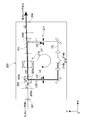
- FIG. 5 is a schematic diagram illustrating a configuration example of an optical amplifying device according to the third embodiment.
- This optical amplifying apparatus 300 can amplify broadband laser light including laser light having a plurality of wavelengths.
- each of the laser beams having the wavelengths ⁇ 1 and ⁇ 2 is referred to as a laser beam ⁇ 1 and a laser beam ⁇ 2.
- the input laser beam I including the laser beams ⁇ 1 and ⁇ 2 is input from the input unit 301 and enters the isolator unit 302 as the first laser beam L1.
- a crystal rotator 307 having natural optical rotation is used as the conversion element disposed at the subsequent stage of the Faraday rotator 306.
- the rotation angle by the Faraday rotator 306 depends on the wavelength of the incident laser light.
- the wavelength dependence of the rotation angle of the Faraday rotator 306 can be compensated by the wavelength dependence of the rotation angle by the crystal rotator 307.
- both the laser beams ⁇ 1 and ⁇ 2 are converted from P-polarized light to S-polarized light by the Faraday rotator 306 and the crystal rotator 307.
- the optical amplifying unit 303 includes a wavelength separation mirror 320, a reflection mirror 321, a plurality of SOAs 314a and 314b, a reflection mirror 322, and a multiplexing mirror 323.
- the wavelength separation mirror 320 reflects the laser beam ⁇ 1 of the first laser beam L1 emitted from the second PBS 308 to the circular optical path P2 toward the SOA 314a and transmits the laser beam ⁇ 2.
- the reflection mirror 321 reflects the laser beam ⁇ 2 transmitted through the wavelength separation mirror 320 toward the SOA 314b.
- the wavelength separation mirror 320 and the reflection mirror 321 constitute a separation unit that separates the first laser light L1 into a plurality of separation laser lights for each wavelength according to the present embodiment.
- the laser beams ⁇ 1 and ⁇ 2 correspond to a plurality of separated laser beams.
- the first filter unit 311 is disposed between the second PBS 308 and the separation unit.
- the SOAs 314a and 314b amplify the laser beams ⁇ 1 and ⁇ 2.
- a plurality of SOAs 314 and a and 314b having different optical amplification characteristics according to the wavelengths ⁇ 1 and ⁇ 2 of the laser light high-accuracy optical amplification is possible.
- the reflection mirror 322 reflects the laser beam ⁇ 2 amplified by the SOA 314b toward the multiplexing mirror 323 along the y direction.
- the combining mirror 323 combines the laser light ⁇ 1 amplified by the SOA 314a and the laser light ⁇ 2 reflected by the reflecting mirror 322, and emits the resultant light along the y direction.
- the amplified laser beams ⁇ 1 and ⁇ 2 are incident on the first PBS 305 as the second laser beam L2.
- the second laser beam L2 is emitted to the output unit 304 via the isolator unit 302.
- the reflection mirror 322 and the combining mirror 323 constitute a combining unit that can combine the laser beams ⁇ 1 and ⁇ 2 amplified by the plurality of SOAs 314a and 314b according to the present embodiment.
- the second filter unit 317 is disposed between the first PBS 305 and the synthesis unit.
- the wavelengths of the laser beams ⁇ 1 and ⁇ 2 having a plurality of wavelengths, the number of the plurality of laser beams included in the input laser beam I, and the like are not limited.
- the same number of SOAs may be arranged for each of laser beams having different wavelengths.
- each of the laser beams having a plurality of wavelengths may be individually input to the optical amplifying apparatus 300 at a predetermined timing and amplified.
- a plurality of excitation lights can be amplified.
- the embodiment is not limited to this.
- FIG. 6 is a schematic diagram illustrating a configuration example of an optical amplifying device according to the fourth embodiment.
- FIG. 6A is a schematic diagram illustrating the entire optical amplification layer device 400.
- FIG. 6B is a schematic view of the mirror unit 430 configured in the optical amplification unit 403 as seen from the x direction.
- the second PBS 408 is arranged with its optical axis rotated by 45 degrees. That is, the second PBS 108 shown in FIG. 2 is configured to be inclined 45 degrees toward the back side of the drawing with the optical axis direction (x direction) of the first laser light L1 as the rotation axis.
- the first laser light L1 reflected by the second PBS 408 is emitted at an angle of 45 degrees upward (z direction) from the xy plane direction.
- the mirror unit 430 is configured to return the first laser beam L1 to the xy plane in which the circulating optical path P2 is configured.
- the first laser light L1 emitted from the second PBS 408 is reflected by the first mirror 431 toward the second mirror 432.
- the second mirror 423 is disposed in the xy plane, and reflects the first laser light L1 reflected by the first mirror 431 toward the first filter unit 411 along the y direction. It can be said that the optical path in the mirror unit 430 is also a part of the circulating optical path P2.
- the optical amplification method according to the present technology can be realized even when the conversion unit 410 includes only the Faraday rotator 406.
- the configuration of the conversion unit 410 can be simplified, and the size of the apparatus can be reduced.
- the P-polarized first laser light L1 is not converted to S-polarized light.
- the first laser beam L1 is converted into S-polarized light by being reflected by the second PBS 408.
- the second PBS 408 converts the first laser light L1 whose polarization state has been converted by the Faraday rotator 406 into S-polarized light and emits it.
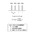
- FIG. 7 is a schematic diagram for explaining this, and is a diagram showing a waveform of a pulse laser beam.
- the amplification operation Amp by the SOA is executed at the same cycle as the pulse cycle Tp of the pulse laser beam. That is, the amplification operation Amp is executed in accordance with the timing at which the pulse enters the SOA. Then, at substantially the same timing, amplified laser light is emitted from the emission end of the SOA.
- T1 L / C L: Optical path length of the circulating optical path (m) C ... speed of light (in air: 3 ⁇ 10 8 m / s)
- the optical path length L of the circuit is set so that the value T1 is different from an integer multiple of the pulse period Tp, that is, the following equation is satisfied.
- optical amplification device and the light source device according to the present technology are applied to a microscope system.
- the optical amplification device and the light source device according to the present technology can be applied to various systems in the medical / biological field such as an endoscope system.
- the present technology can be applied to systems and devices in various fields such as an optical recording system and a semiconductor exposure apparatus.
- a configuration for amplifying each of ⁇ 2 and the like may be arbitrarily applied to the optical amplifying device according to another embodiment.
- various techniques and configurations described in the first to fourth embodiments may be employed.
- this technique can also take the following structures.
- a conversion unit including a Faraday rotator capable of converting the polarization state of laser light; A first laser beam that has a first incident port and a second incident port that is different from the first incident port and is a laser beam in a first polarization state that is incident on the first incident port.
- a second optical beam that emits a second laser beam, which is a laser beam having a second polarization state different from the first polarization state incident on the second entrance, toward the conversion unit.
- the first laser beam whose polarization state is converted by the conversion unit can be emitted as the laser beam of the second polarization state, and the second laser beam whose polarization state is converted by the conversion unit is externally used.
- a second optical element capable of emitting light toward the output to An optical amplifying element that amplifies the first laser light emitted as the laser light in the second polarization state by the second optical element, and the amplified first laser light is converted into the first laser light;
- An optical amplifying apparatus comprising: an optical amplifying unit that causes the optical element to enter the second incident port as the second laser beam.
- the optical amplification device includes a conversion element that converts the first laser light whose polarization state is converted by the Faraday rotator into laser light of the second polarization state
- the second optical element is an optical amplification device that emits the first laser light converted into the laser light in the second polarization state by the conversion element.
- the optical amplification device is an optical amplifying device that converts the first laser light whose polarization state is converted by the Faraday rotator into a laser beam having the second polarization state and emits the laser light.
- the optical amplification device is a crystal rotator which is an optical crystal having optical rotation, or a half-wave plate.
- the optical amplification device has an incident part on which the first laser light emitted from the second optical element is incident, and an emission part from which the amplified first laser light is emitted
- the optical amplification unit is disposed between the second optical element and the incident unit, and includes a first filter unit that regulates first unnecessary light that travels from the second optical element to the incident unit, and the first optical unit. And a second filter unit that is disposed between the first optical element and the emission unit and restricts second unnecessary light that travels from the first optical element to the emission unit.
- the optical amplification device includes: a separation unit capable of separating the first laser beam emitted from the second optical element into a plurality of separated laser beams for each wavelength; and each of the separated plurality of separated laser beams.
- An optical amplifying device comprising: a plurality of optical amplifying elements that amplify the light; and a combining unit capable of combining the plurality of separated lights amplified by the plurality of optical amplifying elements.
- the optical amplifying device is disposed between the second optical element and the separation unit, and includes a first filter unit that regulates first unnecessary light that travels from the second optical element to the separation unit, and the first filter unit. And a second filter unit that is disposed between the first optical element and the combining unit and restricts second unnecessary light traveling from the first optical element to the combining unit.
- the optical amplification device according to (5) or (7), The first filter unit spatially filters the first unnecessary light
- the second filter unit is an optical amplification device that spatially filters the second unnecessary light.
- the optical amplification device (9) The optical amplification device according to (8), The first optical element transmits the first laser light incident on the first incident port onto a predetermined optical path toward the conversion unit, and enters the second incident port. An optical amplifying apparatus that reflects laser light toward the conversion unit so as to travel obliquely at a predetermined angle from the predetermined optical path. (10) The optical amplification device according to (9), The optical amplification device, wherein the predetermined angle is included in a range of not less than ⁇ 2 degrees and not more than +2 degrees.
- the optical amplifying device according to any one of (1) to (10),
- the first optical element emits a pulsed laser beam incident on the first incident port toward the conversion unit as the first laser beam
- the optical amplification element has an incident part on which the first laser light emitted from the second optical element is incident, and an emission part from which the amplified first laser light is emitted
- the optical amplifying unit is configured such that an optical path length of a circular optical path from the emitting unit to the incident unit via the first optical element, the converting unit, and the second optical element
- An optical amplifying apparatus that is set so that a value divided by a speed is different from an integer multiple of a pulse period of the pulse laser beam.
- L1 First laser light
- L2 Second laser light
- L3 First unnecessary light
- P1 Linear optical path
- P2 Circulating optical path
- Light source device 30 DESCRIPTION OF SYMBOLS 40 ...
- Laser light source part 100, 200, 300, 400 ...
- Optical amplification apparatus 103, 303, 403 ...
- PBS polarization beam splitter
- second PBS 110, 210, 410 conversion unit 111, 211, 311, 411 ... first filter unit 114, 214, 314a, 314b ... SOA 114a, 214a ... incidence end 114b, 214b ... emission end 117, 217, 317 ... second filter section 1000 ... microscope system
Abstract
This optical amplification device is provided with: a conversion unit capable of converting polarization state; a first optical element, which has first and second incident ports, and which outputs, toward the conversion unit, a first laser beam inputted to the first incident port, said first laser beam being in a first polarization state, and a second laser beam inputted to the second incident port, said second laser beam being in a second polarization state; a second optical element, which is capable of outputting, as a laser beam in the second polarization state, the first laser beam the polarization state of which has been converted, and which is capable of outputting, toward an output unit to the outside, the second laser beam the polarization state of which has been converted; and an optical amplification unit, which amplifies the first laser beam outputted as the laser beam in the second polarization state by means of the second optical element, and which inputs, as the second laser beam, the amplified first laser beam to the second incident port of the first optical element.
Description
本技術は、光増幅装置、及びこれを用いた光源装置に関する。
The present technology relates to an optical amplification device and a light source device using the same.
特許文献1には、MLLD(Mode Locked Laser Diode:モードロックレーザ)とSOA(Semiconductor Optical Amp:半導体光増幅器)とを組み合わせたMOPA(Master Oscillator Power Amplifier)型の光源を、記録用光源として備えた光記録システムについて記載されている。特許文献1の図2等に示されるように、MLLD部とSOAとの間には、1/4波長板と偏光ビームスプリッタとの組み合わせによるアイソレータが配置される。このアイソレータにより、SOAの入射端から発生され、反射等により再びSOAに戻ってくる不要な戻り光(自己入射成分)が除去されている(特許文献1の明細書段落[0006][0044]等)。
Patent Document 1 includes a MOPA (Master Oscillator Power Amplifier) type light source that combines MLLD (Mode Locked Laser Diode) and SOA (Semiconductor Optical Amp) as a recording light source. An optical recording system is described. As shown in FIG. 2 of Patent Document 1, an isolator based on a combination of a quarter wavelength plate and a polarization beam splitter is disposed between the MLLD unit and the SOA. With this isolator, unnecessary return light (self-incident component) generated from the incident end of the SOA and returning to the SOA again by reflection or the like is removed (paragraphs [0006] and [0044] in the specification of Patent Document 1) ).
特許文献2には、LPP(Laser Produced Plasma:レーザ励起プラズマ)方式のEUV(Extreme Ultraviolet)光生成装置用のレーザ装置について記載されている。特許文献2の図5等に示されるように、レーザ装置は、マスタオシレータ(MO)と複数の増幅器(PA)と、複数のファラデーアイソレータとを有する。各増幅器を挟み込むように、ファラデーアイソレータがそれぞれ配置される。これにより下流側(出射端側)に配置された増幅器から発生するASE(Amplified Spontaneous Emission:自然放出光)や、ターゲットからの戻り光が、増幅器に入射することが防止されている(特許文献2の明細書段落[0038][0062])
Patent Document 2 describes a laser device for an LPP (Laser Produced Plasma) type EUV (Extreme Ultraviolet) light generation device. As shown in FIG. 5 and the like of Patent Document 2, the laser apparatus includes a master oscillator (MO), a plurality of amplifiers (PA), and a plurality of Faraday isolators. Faraday isolators are arranged so as to sandwich each amplifier. As a result, ASE (AmplifiedtanSpontaneous Emission: spontaneous emission light) generated from the amplifier arranged on the downstream side (outgoing end side) and return light from the target are prevented from entering the amplifier (Patent Document 2). [Paragraphs [0038] [0062])
このように光増幅装置においては、不要な戻り光が入射してしまうことを防止することが要求される。そのために例えばSOA等の前後に光アイソレータを配置することが考えられるが、高価な光アイソレータを2つ用いる場合、装置が高価になるとともに小型化も困難である。
Thus, in the optical amplification device, it is required to prevent unnecessary return light from entering. For this purpose, for example, it is conceivable to arrange optical isolators before and after the SOA or the like, but when two expensive optical isolators are used, the apparatus becomes expensive and difficult to downsize.
以上のような事情に鑑み、本技術の目的は、光増幅素子への戻り光の入射を防止可能であり、小型化及び低コスト化を実現可能とする光増幅装置、及びこれを用いた光源装置を提供することにある。
In view of the circumstances as described above, an object of the present technology is to provide an optical amplifying device that can prevent the return light from entering the optical amplifying element, and that can be reduced in size and cost, and a light source using the same. To provide an apparatus.
上記目的を達成するため、本技術の一形態に係る光増幅装置は、変換部と、第1の光学素子と、第2の光学素子と、光増幅部とを具備する。
前記変換部は、レーザ光の偏光状態を変換可能なファラデー回転子を含む。
前記第1の光学素子は、第1の入射口と、前記第1の入射口とは異なる第2の入射口とを有し、前記第1の入射口に入射する第1の偏光状態のレーザ光である第1のレーザ光、及び前記第2の入射口に入射する前記第1の偏光状態とは異なる第2の偏光状態のレーザ光である第2のレーザ光を、前記変換部に向けてそれぞれ出射する。
前記第2の光学素子は、前記変換部により偏光状態が変換された前記第1のレーザ光を前記第2の偏光状態のレーザ光として出射可能であり、前記変換部により偏光状態が変換された前記第2のレーザ光を外部への出力部に向けて出射可能である。
前記光増幅部は、前記第2の光学素子により前記第2の偏光状態のレーザ光として出射された前記第1のレーザ光を増幅する光増幅素子を有し、前記増幅された前記第1のレーザ光を前記第1の光学素子の前記第2の入射口に前記第2のレーザ光として入射させる。 In order to achieve the above object, an optical amplification device according to an embodiment of the present technology includes a conversion unit, a first optical element, a second optical element, and an optical amplification unit.
The conversion unit includes a Faraday rotator capable of converting a polarization state of laser light.
The first optical element has a first incident port and a second incident port that is different from the first incident port, and is a laser in a first polarization state that is incident on the first incident port. The first laser beam, which is light, and the second laser beam, which is a laser beam having a second polarization state different from the first polarization state incident on the second incident port, are directed to the conversion unit. Respectively.
The second optical element can emit the first laser light whose polarization state is converted by the conversion unit as laser light of the second polarization state, and the polarization state is converted by the conversion unit. The second laser beam can be emitted toward the output unit to the outside.
The optical amplification unit includes an optical amplification element that amplifies the first laser light emitted as the laser light in the second polarization state by the second optical element, and the amplified first Laser light is incident on the second incident port of the first optical element as the second laser light.
この光増幅装置では、第1の光学素子に入射する第1のレーザ光が増幅され、第2のレーザ光として再び第1の光学素子に入射される。そして当該第2のレーザ光が、第1の光学素子、変換部、及び第2の光学素子を介して、外部への出力部に出射される。これにより例えば単体の光アイソレータにより上記の構成を実現させることができる。従って光増幅素子への戻り光の入射を防止しつつ、装置の小型化及び低コスト化を実現することが可能となる。
In this optical amplifying apparatus, the first laser light incident on the first optical element is amplified and again incident on the first optical element as the second laser light. Then, the second laser light is emitted to the output unit to the outside through the first optical element, the conversion unit, and the second optical element. Thereby, for example, the above-described configuration can be realized by a single optical isolator. Therefore, it is possible to reduce the size and cost of the apparatus while preventing the return light from entering the optical amplifying element.
前記変換部は、前記ファラデー回転子により偏光状態が変換された前記第1のレーザ光を前記第2の偏光状態のレーザ光に変換する変換素子を有してもよい。この場合、前記第2の光学素子は、前記変換素子により前記第2の偏光状態のレーザ光に変換された前記第1のレーザ光を出射してもよい。
変換部により第1のレーザ光の偏光状態が第2の偏光状態に変換されるので、第2の光学素子の配置構成等をシンプルにすることができる。 The conversion unit may include a conversion element that converts the first laser light whose polarization state is converted by the Faraday rotator into laser light of the second polarization state. In this case, the second optical element may emit the first laser light converted into the laser light in the second polarization state by the conversion element.
Since the polarization state of the first laser light is converted to the second polarization state by the conversion unit, the arrangement configuration of the second optical element can be simplified.
前記第2の光学素子は、前記ファラデー回転子により偏光状態が変換された前記第1のレーザ光を前記第2の偏光状態のレーザ光に変換して出射してもよい。
これにより変換部の構成をシンプルにすることが可能となり、装置の小型化等を図ることができる。 The second optical element may convert the first laser beam, the polarization state of which has been converted by the Faraday rotator, into a laser beam having the second polarization state, and emit the laser beam.
As a result, the configuration of the conversion unit can be simplified, and the size of the apparatus can be reduced.
前記変換素子は、旋光性を有する光学結晶である結晶旋光子、又は1/2波長板であってもよい。
変換素子としてこれらの部材を用いることで、簡単に変換部を実現することができる。 The conversion element may be a crystal rotator, which is an optical crystal having optical activity, or a half-wave plate.
By using these members as the conversion element, the conversion unit can be easily realized.
変換素子としてこれらの部材を用いることで、簡単に変換部を実現することができる。 The conversion element may be a crystal rotator, which is an optical crystal having optical activity, or a half-wave plate.
By using these members as the conversion element, the conversion unit can be easily realized.
前記光増幅素子は、前記第2の光学素子により出射された前記第1のレーザ光が入射する入射部と、増幅された前記第1のレーザ光が出射する出射部とを有してもよい。この場合、前記光増幅部は、前記第2の光学素子及び前記入射部の間に配置され前記第2の光学素子から前記入射部に進む第1の不要光を規制する第1のフィルタ部と、前記第1の光学素子及び前記出射部の間に配置され前記第1の光学素子から前記出射部に進む第2の不要光を規制する第2のフィルタ部とを有してもよい。
これにより光増幅素子への不要光の入射を十分に防止することができる。 The optical amplification element may include an incident portion on which the first laser light emitted from the second optical element is incident, and an emission portion from which the amplified first laser light is emitted. . In this case, the light amplifying unit is disposed between the second optical element and the incident unit, and the first filter unit restricts the first unnecessary light traveling from the second optical element to the incident unit. And a second filter unit that is disposed between the first optical element and the emission unit and restricts second unnecessary light that travels from the first optical element to the emission unit.
Thereby, it is possible to sufficiently prevent the unnecessary light from entering the optical amplifying element.
前記変換素子は、旋光性を有する光学結晶である結晶旋光子であってもよい。この場合、前記光増幅部は、前記第2の光学素子により出射された前記第1のレーザ光を波長ごとに複数の分離レーザ光に分離可能な分離部と、前記分離された複数の分離レーザ光の各々を増幅する複数の光増幅素子と、前記複数の光増幅素子により増幅された前記複数の分離光を合成可能な合成部とを有してもよい。
これにより複数の波長のレーザ光を含む広帯域のレーザ光を増幅することが可能となる。 The conversion element may be a crystal rotator which is an optical crystal having optical activity. In this case, the optical amplification unit includes a separation unit capable of separating the first laser light emitted from the second optical element into a plurality of separated laser beams for each wavelength, and the plurality of separated separation lasers. You may have a some optical amplification element which amplifies each of light, and the synthetic | combination part which can synthesize | combine the said some separated light amplified by the said some optical amplification element.
As a result, it is possible to amplify broadband laser light including laser light having a plurality of wavelengths.
前記光増幅部は、前記第2の光学素子及び前記分離部の間に配置され前記第2の光学素子から前記分離部に進む第1の不要光を規制する第1のフィルタ部と、前記第1の光学素子及び前記合成部の間に配置され前記第1の光学素子から前記合成部に進む第2の不要光を規制する第2のフィルタ部とを有してもよい。
これにより複数の光増幅素子への不要光の入射を十分に防止することができる。
The optical amplification unit is disposed between the second optical element and the separation unit, and includes a first filter unit that regulates first unnecessary light that travels from the second optical element to the separation unit, and the first filter unit. And a second filter unit that is disposed between the first optical element and the combining unit and restricts second unnecessary light that travels from the first optical element to the combining unit.
Thereby, it is possible to sufficiently prevent the unnecessary light from entering the plurality of optical amplifying elements.
前記第1のフィルタ部は、前記第1の不要光を空間的にフィルタリングしてもよい。また前記第2のフィルタ部は、前記第2の不要光を空間的にフィルタリングしてもよい。
空間フィルタを用いることで簡単な構成で不要光の入射を防止することができる。 The first filter unit may spatially filter the first unnecessary light. The second filter unit may spatially filter the second unnecessary light.
By using a spatial filter, it is possible to prevent unnecessary light from entering with a simple configuration.
空間フィルタを用いることで簡単な構成で不要光の入射を防止することができる。 The first filter unit may spatially filter the first unnecessary light. The second filter unit may spatially filter the second unnecessary light.
By using a spatial filter, it is possible to prevent unnecessary light from entering with a simple configuration.
前記第1の光学素子は、前記第1の入射口に入射する前記第1のレーザ光を前記変換部に向かう所定の光路上に透過させ、前記第2の入射口に入射する前記第2のレーザ光を前記所定の光路から所定の角度で斜めに進むように前記変換部に向けて反射させてもよい。
これにより第1及び第2のフィルタ部による各フィルタリングが十分に実行され、光増幅素子への不要光の入射を十分に防止することができる。 The first optical element transmits the first laser light incident on the first incident port onto a predetermined optical path toward the conversion unit, and enters the second incident port. The laser beam may be reflected toward the conversion unit so as to travel obliquely at a predetermined angle from the predetermined optical path.
Thereby, each filtering by the 1st and 2nd filter part is fully performed, and incidence | injection of the unnecessary light to an optical amplification element can fully be prevented.
前記所定の角度は、-2度以上+2度以下の範囲に含まれてもよい。
これによりレーザ光の増幅及び不要光の規制が高い精度で実現される。 The predetermined angle may be included in a range of not less than −2 degrees and not more than +2 degrees.
Thereby, amplification of laser light and regulation of unnecessary light are realized with high accuracy.
これによりレーザ光の増幅及び不要光の規制が高い精度で実現される。 The predetermined angle may be included in a range of not less than −2 degrees and not more than +2 degrees.
Thereby, amplification of laser light and regulation of unnecessary light are realized with high accuracy.
前記第1の光学素子は、前記第1の入射口に入射するパルスレーザ光を、前記第1のレーザ光として前記変換部に向けて出射してもよい。この場合、前記光増幅素子は、前記第2の光学素子により出射された前記第1のレーザ光が入射する入射部と、増幅された前記第1のレーザ光が出射する出射部とを有してもよい。また前記光増幅部は、前記出射部から、前記第1の光学素子、前記変換部、及び前記第2の光学素子を介した前記入射部までの周回光路の光路長が、当該光路長を光の速度で割った値が前記パルスレーザ光のパルス周期の整数倍の値と異なるように設定されてもよい。
これにより仮に増幅されたレーザ光の一部が不要光として周回光路を通って入射部に入射したとしても、その入射のタイミングと光増幅素子による光増幅の動作タイミングとをずらすことができる。この結果、不要光の入射による影響を十分に抑えることができる。 The first optical element may emit a pulse laser beam incident on the first incident port toward the conversion unit as the first laser beam. In this case, the optical amplifying element has an incident part on which the first laser light emitted from the second optical element is incident, and an emitting part from which the amplified first laser light is emitted. May be. The optical amplifying unit is configured so that an optical path length of a circulating optical path from the emitting unit to the incident unit through the first optical element, the converting unit, and the second optical element is the optical path length. The value divided by the speed may be set to be different from a value that is an integral multiple of the pulse period of the pulse laser beam.
As a result, even if part of the amplified laser light enters the incident portion as unnecessary light through the circulating optical path, the incident timing and the optical amplification operation timing by the optical amplifying element can be shifted. As a result, it is possible to sufficiently suppress the influence due to the incidence of unnecessary light.
上記目的を達成するため、本技術の一形態に係る光源装置は、光源部と、変換部と、第1の光学素子と、第2の光学素子と、光増幅部とを具備する。
前記光源部は、レーザ光を出射する。
前記変換部は、レーザ光の偏光状態を変換可能なファラデー回転子を含む。
前記第1の光学素子は、第1の入射口と、前記第1の入射口とは異なる第2の入射口とを有し、前記光源部から前記第1の入射口に向けて出射された第1の偏光状態のレーザ光である第1のレーザ光、及び前記第2の入射口に入射する前記第1の偏光状態とは異なる第2の偏光状態のレーザ光である第2のレーザ光を、前記変換部に向けてそれぞれ出射する。
前記第2の光学素子は、前記変換部により偏光状態が変換された前記第1のレーザ光を前記第2の偏光状態のレーザ光として出射可能であり、前記変換部により偏光状態が変換された前記第2のレーザ光を外部への出力部に向けて出射可能である。
前記光増幅部は、前記第2の光学素子により前記第2の偏光状態のレーザ光として出射された前記第1のレーザ光を増幅する光増幅素子を有し、前記増幅された前記第1のレーザ光を前記第1の光学素子の前記第2の入射口に前記第2のレーザ光として入射させる。 In order to achieve the above object, a light source device according to an embodiment of the present technology includes a light source unit, a conversion unit, a first optical element, a second optical element, and an optical amplification unit.
The light source unit emits laser light.
The conversion unit includes a Faraday rotator capable of converting a polarization state of laser light.
The first optical element has a first incident port and a second incident port different from the first incident port, and is emitted from the light source unit toward the first incident port. A first laser beam, which is a laser beam in a first polarization state, and a second laser beam, which is a laser beam in a second polarization state different from the first polarization state incident on the second incident port. Are respectively emitted toward the converter.
The second optical element can emit the first laser light whose polarization state is converted by the conversion unit as laser light of the second polarization state, and the polarization state is converted by the conversion unit. The second laser beam can be emitted toward the output unit to the outside.
The optical amplification unit includes an optical amplification element that amplifies the first laser light emitted as the laser light in the second polarization state by the second optical element, and the amplified first Laser light is incident on the second incident port of the first optical element as the second laser light.
以上のように、本技術によれば、光増幅素子への戻り光の入射を防止可能であり、小型化及び低コスト化が実現可能となる。なお、ここに記載された効果は必ずしも限定されるものではなく、本開示中に記載されたいずれかの効果であってもよい。
As described above, according to the present technology, it is possible to prevent the return light from entering the optical amplifying element, and it is possible to realize downsizing and cost reduction. Note that the effects described here are not necessarily limited, and may be any of the effects described in the present disclosure.
以下、本技術に係る実施形態を、図面を参照しながら説明する。
Hereinafter, embodiments of the present technology will be described with reference to the drawings.
<第1の実施形態>
[顕微鏡システム]
図1は、本技術の第1の実施形態に係る顕微鏡システムの構成例を模式的に示すブロック図である。顕微鏡システム1000として、例えば生体解析用のレーザ走査型顕微鏡が用いられる。その他の用途に用いられる種々の顕微鏡にも、本技術は適用可能である。 <First Embodiment>
[Microscope system]
FIG. 1 is a block diagram schematically illustrating a configuration example of a microscope system according to the first embodiment of the present technology. As themicroscope system 1000, for example, a laser scanning microscope for biological analysis is used. The present technology can also be applied to various microscopes used for other purposes.
[顕微鏡システム]
図1は、本技術の第1の実施形態に係る顕微鏡システムの構成例を模式的に示すブロック図である。顕微鏡システム1000として、例えば生体解析用のレーザ走査型顕微鏡が用いられる。その他の用途に用いられる種々の顕微鏡にも、本技術は適用可能である。 <First Embodiment>
[Microscope system]
FIG. 1 is a block diagram schematically illustrating a configuration example of a microscope system according to the first embodiment of the present technology. As the
図1に示すように、顕微鏡システム1000は、顕微鏡本体10と、制御部20と、本技術に係る光源装置30とを有する。顕微鏡本体10は、光源装置30から出射されたレーザ光をサンプル(試料)上にスポット集光し、これを3次元で走査する。当該走査により得られたサンプルの拡大像がデジタル化され、サンプルの画像データ群が生成される。
As shown in FIG. 1, the microscope system 1000 includes a microscope main body 10, a control unit 20, and a light source device 30 according to the present technology. The microscope main body 10 spot-condenses the laser light emitted from the light source device 30 on a sample (sample), and scans this in three dimensions. The enlarged image of the sample obtained by the scanning is digitized, and a sample image data group is generated.
顕微鏡本体10は、例えばサンプルが載置されるステージ、レーザ光を走査する走査光学系、サンプルの拡大像を生成する拡大光学系、及びデジタルカメラ等を有する(いずれも図示なし)。顕微鏡本体10の具体的な構成や、レーザ光を走査する方法等は限定されない。
The microscope main body 10 includes, for example, a stage on which a sample is placed, a scanning optical system that scans laser light, a magnifying optical system that generates an enlarged image of the sample, a digital camera, and the like (all not shown). A specific configuration of the microscope main body 10, a method of scanning with laser light, and the like are not limited.
制御部20は、顕微鏡本体10及び光源装置30の各々の動作を制御する。制御部20の具体的な構成は限定されず、周知の技術が適宜用いられてもよい。
The control unit 20 controls the operations of the microscope main body 10 and the light source device 30. The specific configuration of the control unit 20 is not limited, and a known technique may be used as appropriate.
光源装置30は、レーザ光源部40と、2つのISO部(光アイソレータ部)50と、SOA部60と、波長変換部70と、本実施形態に係る光増幅装置100とを有する。レーザ光源部40は、レーザ光を出射する。レーザ光源部40として、例えばパルスレーザ光を出射するMLLD等が用いられる。その他、連続レーザ光を出射するレーザ光源等、種々のレーザ光源が用いられてよい。
The light source device 30 includes a laser light source unit 40, two ISO units (optical isolator units) 50, an SOA unit 60, a wavelength conversion unit 70, and the optical amplification device 100 according to the present embodiment. The laser light source unit 40 emits laser light. As the laser light source unit 40, for example, an MLLD that emits pulsed laser light or the like is used. In addition, various laser light sources such as a laser light source that emits continuous laser light may be used.
SOA部60は、図示しないSOAを有する。SOAは、印加される制御電流に応じて、レーザ光源部40から出射されたレーザ光を増幅する。図1に示すようにSOA部60の前段及び後段に、ISO部50がそれぞれ配置される。ISO部50は、順方向のレーザ光の通過のみを可能とする。これら2つのISO部50により、SOA部60のSOAに不要な戻り光が入射することが防止されている。
The SOA unit 60 has an SOA (not shown). The SOA amplifies the laser light emitted from the laser light source unit 40 in accordance with the applied control current. As shown in FIG. 1, the ISO unit 50 is arranged at the front stage and the rear stage of the SOA unit 60. The ISO unit 50 allows only passage of laser light in the forward direction. These two ISO parts 50 prevent unnecessary return light from entering the SOA of the SOA part 60.
波長変換部70は、SOA部50により増幅されたレーザ光の波長を変換する。波長変換部70として、例えばLBOを有する波長変換モジュール(Optical Parametric Oscillation:OPO)等が用いられる。その他の波長変換モジュールが用いられてもよい。
The wavelength conversion unit 70 converts the wavelength of the laser light amplified by the SOA unit 50. As the wavelength converter 70, for example, a wavelength conversion module (Optical Parametric Oscillation: OPO) having LBO is used. Other wavelength conversion modules may be used.
例えば光源装置30が、二光子励起の光源として用いられる場合、レーザ光源部40から波長が約405nmのレーザ光が出射される。そして波長変換部70により、高い密度で二光子の効果を生じさせる波長(約900nm-1300nm程度)に波長が変換される。なおレーザ光源部40から出射されるレーザ光の波長や、変換可能な波長の範囲等は限定されない。
For example, when the light source device 30 is used as a light source for two-photon excitation, laser light having a wavelength of about 405 nm is emitted from the laser light source unit 40. Then, the wavelength conversion unit 70 converts the wavelength to a wavelength (about 900 nm to 1300 nm) that produces a two-photon effect at a high density. The wavelength of the laser light emitted from the laser light source unit 40, the range of convertible wavelengths, and the like are not limited.
本技術に係る光増幅装置100は、波長変換部70により波長が変換されたレーザ光を増幅する。レーザ光源部40、及び以下に示す光増幅装置100を備えた光源装置であれば、図1に例示する構成に限定されず、本技術に係る光源装置として実施可能である。
The optical amplification device 100 according to the present technology amplifies the laser light whose wavelength is converted by the wavelength conversion unit 70. The light source device including the laser light source unit 40 and the optical amplification device 100 described below is not limited to the configuration illustrated in FIG. 1 and can be implemented as a light source device according to the present technology.
[光増幅装置]
図2は、本実施形態に係る光増幅装置の構成例を示す概略図である。なお以下の説明では、光増幅装置100内を進むレーザ光の進行方向を基準として、前段、後段、下流側、上流側等の文言を用いる。すなわちレーザ光が入射してくる側が前段及び上流側となり、レーザ光が出射していく側が後段及び下流側となる。 [Optical amplifier]
FIG. 2 is a schematic diagram illustrating a configuration example of the optical amplifying device according to the present embodiment. In the following description, terms such as a front stage, a rear stage, a downstream side, and an upstream side are used with reference to the traveling direction of the laser light that travels in theoptical amplifying apparatus 100. That is, the side on which the laser light is incident is the front stage and the upstream side, and the side from which the laser light is emitted is the rear stage and the downstream side.
図2は、本実施形態に係る光増幅装置の構成例を示す概略図である。なお以下の説明では、光増幅装置100内を進むレーザ光の進行方向を基準として、前段、後段、下流側、上流側等の文言を用いる。すなわちレーザ光が入射してくる側が前段及び上流側となり、レーザ光が出射していく側が後段及び下流側となる。 [Optical amplifier]
FIG. 2 is a schematic diagram illustrating a configuration example of the optical amplifying device according to the present embodiment. In the following description, terms such as a front stage, a rear stage, a downstream side, and an upstream side are used with reference to the traveling direction of the laser light that travels in the
光増幅装置100は、入力レーザ光Iが入力される入力部101と、アイソレータ部102と、光増幅部103と、増幅されたレーザ光を外部へ出力する出力部104とを有する。出力部104から出力されるレーザ光が、出力レーザ光Oとなる。
The optical amplification apparatus 100 includes an input unit 101 to which an input laser beam I is input, an isolator unit 102, an optical amplification unit 103, and an output unit 104 that outputs the amplified laser beam to the outside. The laser beam output from the output unit 104 becomes the output laser beam O.
図2に示すように、アイソレータ部102は、入力部101から入力された入力レーザ光Iを受光する。アイソレータ部102は、図中のx方向に沿って略直線状に配置された第1のPBS(偏光ビームスプリッタ)105、ファラデー回転子106、結晶旋光子107、及び第2のPBS108を有する。これらの部材は、上流から下流にかけて、この順番で配置される。以下、第1のPBS105から第2のPBS108までの直線状の光路を直線光路P1と記載する。
As shown in FIG. 2, the isolator unit 102 receives an input laser beam I input from the input unit 101. The isolator unit 102 includes a first PBS (polarizing beam splitter) 105, a Faraday rotator 106, a crystal rotator 107, and a second PBS 108, which are arranged substantially linearly in the x direction in the figure. These members are arranged in this order from upstream to downstream. Hereinafter, the linear optical path from the first PBS 105 to the second PBS 108 is referred to as a linear optical path P1.
第1のPBS105は、分離面105aに対するP偏光を透過させ、S偏光を反射する。図2に示すように、第1のPBS105の第1の入射面105bがx方向に直交する向きで配置され、当該第1の入射面105bに入射するP偏光が、そのまま直線光路P1上に透過される。
The first PBS 105 transmits P-polarized light to the separation surface 105a and reflects S-polarized light. As shown in FIG. 2, the first incident surface 105b of the first PBS 105 is arranged in a direction orthogonal to the x direction, and the P-polarized light incident on the first incident surface 105b is transmitted as it is onto the linear optical path P1. Is done.
第1の入射面105bとは異なる向きの面であり、図中のy方向に直交する向きとなる面が、第1のPBS105の第2の入射面105cとなる。y方向に沿って第2の入射面105cに入射するS偏光は、直線光路P1上に反射される。
The surface that is in a direction different from the first incident surface 105 b and that is orthogonal to the y direction in the figure is the second incident surface 105 c of the first PBS 105. S-polarized light incident on the second incident surface 105c along the y direction is reflected on the linear optical path P1.
第1のPBS105は、本実施形態において、第1の光学素子に相当する。第1の出射面105bに入射するP偏光は、第1の入射口に入射する第1の偏光状態のレーザ光である第1のレーザ光L1に相当する。また第2の出射面105cに入射するS偏光は、第2の入射口に入射する第2の偏光状態のレーザ光である第2のレーザ光L2に相当する。
The first PBS 105 corresponds to the first optical element in the present embodiment. The P-polarized light incident on the first emission surface 105b corresponds to the first laser light L1 that is the laser light in the first polarization state incident on the first incident port. The S-polarized light incident on the second emission surface 105c corresponds to the second laser light L2 that is the laser light in the second polarization state incident on the second incident port.
なお本実施形態では、入力レーザ光Iが、第1のレーザ光L1として第1の入射面105bに入射する。また第1のPBS105の分離面105aに対するP偏光及びS偏光と同じ偏光状態のレーザ光については、そのままP偏光及びS偏光と記載して説明を行う。
In the present embodiment, the input laser beam I is incident on the first incident surface 105b as the first laser beam L1. Further, laser light having the same polarization state as the P-polarized light and S-polarized light with respect to the separation surface 105a of the first PBS 105 will be described as P-polarized light and S-polarized light as they are.
ファラデー回転子106は、磁性体の光学結晶であり、磁界が与えられることで第1のPBS105から出射されたレーザ光の偏光方向を45度回転させる。結晶旋光子107は、水晶や石英等の自然旋光性を有する光学結晶であり、ファラデー回転子から出射されたレーザ光の偏光方向を、同じ方向に45度回転させる。従って上流側からファラデー回転子106及び結晶旋光子107を通るレーザ光の偏光方向は、90度回転される。すなわちP偏光はS偏光に変換され、S偏光はP偏光に変換される。
The Faraday rotator 106 is a magnetic optical crystal, and rotates the polarization direction of the laser light emitted from the first PBS 105 by 45 degrees when a magnetic field is applied. The crystal rotator 107 is an optical crystal having natural optical rotation such as quartz or quartz, and rotates the polarization direction of the laser light emitted from the Faraday rotator by 45 degrees in the same direction. Therefore, the polarization direction of the laser light passing through the Faraday rotator 106 and the crystal rotator 107 from the upstream side is rotated by 90 degrees. That is, P-polarized light is converted to S-polarized light, and S-polarized light is converted to P-polarized light.
ファラデー回転子106及び結晶旋光子107により、本実施形態に係る変換部110が構成される。また結晶旋光子107は、ファラデー回転子106により偏光状態が変換された第1のレーザ光L1を、S偏光に変換する変換素子に相当する。なお偏光方向の回転は、偏光状態の変換に相当する。
The Faraday rotator 106 and the crystal rotator 107 constitute the conversion unit 110 according to this embodiment. The crystal rotator 107 corresponds to a conversion element that converts the first laser light L1 whose polarization state has been converted by the Faraday rotator 106 into S-polarized light. The rotation of the polarization direction corresponds to the conversion of the polarization state.
偏光方向を45度回転させる変換素子として、結晶旋光子に代えて、1/2波長板が用いられてもよい。いずれにせよこれらの部材を用いることで、シンプルな構成で変換部110を実現可能である。
As the conversion element that rotates the polarization direction by 45 degrees, a half-wave plate may be used instead of the crystal rotator. In any case, by using these members, the conversion unit 110 can be realized with a simple configuration.
第2のPBS108は、変換部110により偏光状態が変換されS偏光となった第1のレーザ光L1を所定の方向(図中ではy方向)に沿って反射させる。また第2のPBS108は、変換部110により偏光状態が変換されP偏光となった第2のレーザ光L2を、出力部104に向けて透過させる。第2のPBS108は、本実施形態において、第2の光学素子に相当する。
The second PBS 108 reflects the first laser light L1 whose polarization state has been converted by the conversion unit 110 to become S-polarized light along a predetermined direction (y direction in the drawing). In addition, the second PBS 108 transmits the second laser light L <b> 2 whose polarization state has been converted by the conversion unit 110 into P-polarized light toward the output unit 104. The second PBS 108 corresponds to a second optical element in the present embodiment.
第1のPBS105、ファラデー回転子106、結晶旋光子107、1/2波長板、第2のPBS108の具体的な構成は限定されず、同様の機能を有する他の光学素子が用いられてもよい。例えばPBSに代えてグラントムソンプリズム等の結晶型偏光分離素子が用いられてもよい。また後段にある部材等にレーザ光を出射する方法は限定されず、透過や反射等が適宜実行されてよい。
Specific configurations of the first PBS 105, the Faraday rotator 106, the crystal rotator 107, the half-wave plate, and the second PBS 108 are not limited, and other optical elements having the same function may be used. . For example, a crystalline polarization separation element such as a Glan-Thompson prism may be used instead of PBS. Further, the method of emitting laser light to a member or the like in the subsequent stage is not limited, and transmission, reflection, or the like may be appropriately performed.
光増幅部103は、第2のPBS108により反射された第1のレーザ光L1を増幅し、第1のPBS105の第2の入射面105cに入射させる。第1のレーザ光L1はS偏光に変換されている。従って第1のPBS105から見ると、第1のレーザ光L1は、第2のレーザ光L2として入射されることになる。
The optical amplifying unit 103 amplifies the first laser light L1 reflected by the second PBS 108 and makes it incident on the second incident surface 105 c of the first PBS 105. The first laser beam L1 is converted to S-polarized light. Accordingly, when viewed from the first PBS 105, the first laser light L1 is incident as the second laser light L2.
図2に示すように光増幅部103は、第1のフィルタ部111と、第1のミラー112と、第1のレンズ113と、光増幅素子としてのSOA114と、第2のレンズ115と、第2のミラー116と、第2のフィルタ部117とを有する。第1のミラー112は、第1のフィルタ部111を通った第1のレーザ光L1を第1のレンズ113に向けて反射する。第1のレンズ113は、第1のレーザ光L1を、SOA114の入射端(入射部)114aに集光する。
As shown in FIG. 2, the optical amplification unit 103 includes a first filter unit 111, a first mirror 112, a first lens 113, an SOA 114 as an optical amplification element, a second lens 115, and a second lens 115. 2 mirrors 116 and a second filter unit 117. The first mirror 112 reflects the first laser light L 1 that has passed through the first filter unit 111 toward the first lens 113. The first lens 113 condenses the first laser light L1 on the incident end (incident part) 114a of the SOA 114.
SOA114は、外部からの電流注入により第1のレーザ光L1を増幅する。第2のレンズ115は、SOA114の出射端(出射部)114bから出射された第1のレーザ光L1を平行化する。第2のミラー116は、平行化された第1のレーザ光L1を、第1のPBS105の第2の入射面105cに向けて反射する。反射された第1のレーザ光L1は、第2のレーザ光L2として、第2のフィルタ部117を通って第2の入射面105cに入射する。
The SOA 114 amplifies the first laser beam L1 by current injection from the outside. The second lens 115 collimates the first laser light L1 emitted from the emission end (emission part) 114b of the SOA 114. The second mirror 116 reflects the collimated first laser light L1 toward the second incident surface 105 c of the first PBS 105. The reflected first laser light L1 enters the second incident surface 105c through the second filter unit 117 as the second laser light L2.
第2の入射面105cに入射した第2のレーザ光L2(増幅された第1のレーザ光L1)は、変換部110によりP偏光に変換され、第2のPBS108を介して出力部104から外部に出力される。これにより本技術に係るレーザ光の増幅方法が終了する。
The second laser light L2 (the amplified first laser light L1) incident on the second incident surface 105c is converted into P-polarized light by the conversion unit 110, and is externally output from the output unit 104 via the second PBS 108. Is output. This completes the laser light amplification method according to the present technology.
ここでSOA114の出射端114bから、第1のPBS105、変換部110、第2のPBS108を介したSOA114の入射端114aまでの光路を、周回光路P2と記載する。この周回光路P2により、アイソレータ部102に入射する入力レーザ光I(第1のレーザ光L1)が、光増幅部114により増幅された後、第2のレーザ光L2として再びアイソレータ部102に導かれる。従って単体の光アイソレータにより、本技術に係る光増幅装置100を実現可能である。
Here, the optical path from the exit end 114b of the SOA 114 to the entrance end 114a of the SOA 114 via the first PBS 105, the conversion unit 110, and the second PBS 108 is referred to as a circulating optical path P2. By this circular optical path P2, the input laser beam I (first laser beam L1) incident on the isolator unit 102 is amplified by the optical amplification unit 114 and then guided again to the isolator unit 102 as the second laser beam L2. . Therefore, the optical amplification device 100 according to the present technology can be realized by a single optical isolator.
また2つの光アイソレータを用いる場合と同様の性能を発揮させることが可能であり、光増幅装置100の外部からの不要な戻り光を遮蔽することができる。この結果、SOA114による安定した光増幅が可能となり、また装置の小型化及び低コスト化を実現することが可能となる。
Further, it is possible to exhibit the same performance as when two optical isolators are used, and unnecessary return light from the outside of the optical amplifying apparatus 100 can be shielded. As a result, it is possible to perform stable optical amplification by the SOA 114, and it is possible to reduce the size and cost of the apparatus.
第1及び第2のフィルタ部111及び117について説明する。SOA114により第1のレーザ光L1が増幅される場合、増幅レーザ光が出射端114bから放射される(前方放射)。また電流注入により発生するASEが、出射端114b及び入射端114aから放射される(前後方放射)。これらの増幅レーザ光やASEの一部が不要光として、周回光路P2を回って他方の端部に入射する場合が起こり得る。
The first and second filter units 111 and 117 will be described. When the first laser light L1 is amplified by the SOA 114, the amplified laser light is emitted from the emission end 114b (forward emission). Further, ASE generated by current injection is emitted from the emission end 114b and the incidence end 114a (front-rear emission). There may occur a case in which a part of these amplified laser light and ASE is incident on the other end of the optical path P2 as unnecessary light.
そこで本実施形態では、第2のPBS118及びSOA114の入射端114aの間に、第2のPBS118から入射端114aに進む第1の不要光を規制する第1のフィルタ部111が配置される。また第1のPBS105及びSOA114の出射端114bの間に、第1のPBS105から出射端114bに進む第2の不要光を規制する第2のフィルタ部117が配置される。
Therefore, in the present embodiment, the first filter unit 111 that restricts the first unnecessary light traveling from the second PBS 118 to the incident end 114a is disposed between the second PBS 118 and the incident end 114a of the SOA 114. In addition, a second filter unit 117 that restricts second unnecessary light traveling from the first PBS 105 to the emission end 114b is disposed between the first PBS 105 and the emission end 114b of the SOA 114.
第1及び第2のフィルタ部111及び117は、各不要光を空間的にフィルタリングすることが可能な空間フィルタである。例えば図2に示すように、第1及び第2のフィルタ部111及び117として、光学スリット119が用いられる。光学スリット119のスリット部分を周回光路P2上に配置することで、周回光路P2からずれて進む不要光を規制することができる。その他、ピンホール等が用いられてもよい。
The first and second filter units 111 and 117 are spatial filters capable of spatially filtering each unnecessary light. For example, as shown in FIG. 2, an optical slit 119 is used as the first and second filter portions 111 and 117. By disposing the slit portion of the optical slit 119 on the orbiting optical path P2, it is possible to regulate unnecessary light that travels away from the orbiting optical path P2. In addition, a pinhole or the like may be used.
例えば図3に示すように、第1及び第2のフィルタ部111'及び117'として、光学スリット119と、これを挟み込む入射側レンズ120a及び出射側レンズ120bとが用いられてもよい。入射側レンズ120a及び出射側レンズ120bは、互いに略等しい構成のレンズであり、互いの焦点位置が光学スリット119の位置に合わせられる。このようなレンズ機構を加えることで、光学スリット119の小型化を図ることができる。また不要光を分離するために必要な光路の長さを短くすることができる。この結果、装置の小型化を実現することができる。
For example, as shown in FIG. 3, as the first and second filter portions 111 ′ and 117 ′, an optical slit 119 and an entrance side lens 120a and an exit side lens 120b sandwiching the optical slit 119 may be used. The incident side lens 120 a and the emission side lens 120 b are lenses having substantially the same configuration, and their focal positions are matched with the position of the optical slit 119. By adding such a lens mechanism, the optical slit 119 can be reduced in size. Further, the length of the optical path necessary for separating unnecessary light can be shortened. As a result, downsizing of the apparatus can be realized.
なお出射側レンズ120bを適宜設計することで、出射側レンズ120bから出射されるレーザ光の光束の大きさが調整されてもよい。その他、第1及び第2のフィルタ部111及び117を実現するために、種々の構成が採用されてよい。また第1及び第2のフィルタ部111及び117が、互いに異なる構成となってもよい。
In addition, the magnitude | size of the light beam of the laser beam radiate | emitted from the output side lens 120b may be adjusted by designing the output side lens 120b suitably. In addition, various configurations may be employed to realize the first and second filter units 111 and 117. The first and second filter units 111 and 117 may have different configurations.
<第2の実施形態>
本技術の第2の実施形態に係る光増幅装置について説明する。これ以降の説明では、上記の実施形態で説明した光増幅装置100における構成及び作用と同様な部分については、その説明を省略又は簡略化する。 <Second Embodiment>
An optical amplifying device according to the second embodiment of the present technology will be described. In the following description, the description of the same part as the configuration and operation in theoptical amplifying device 100 described in the above embodiment will be omitted or simplified.
本技術の第2の実施形態に係る光増幅装置について説明する。これ以降の説明では、上記の実施形態で説明した光増幅装置100における構成及び作用と同様な部分については、その説明を省略又は簡略化する。 <Second Embodiment>
An optical amplifying device according to the second embodiment of the present technology will be described. In the following description, the description of the same part as the configuration and operation in the
図4は、本実施形態に係る光増幅装置の構成例を示す概略図である。この光増幅装置200では、図2に示す光増幅装置100と比べて、第1のPBS205の配置の仕方が異なる。直線光路P1の延在方向をx方向とし、第1のPBS205の第2の入射面205cに向かって進む第2のレーザ光L2(増幅された第1のレーザ光L1)の進行方向をy方向とする。
FIG. 4 is a schematic diagram illustrating a configuration example of the optical amplifying device according to the present embodiment. In this optical amplifying device 200, the arrangement of the first PBS 205 is different from that of the optical amplifying device 100 shown in FIG. The extending direction of the straight optical path P1 is the x direction, and the traveling direction of the second laser light L2 (amplified first laser light L1) traveling toward the second incident surface 205c of the first PBS 205 is the y direction. And
第1のPBS205は、xy平面内で角度θ回転されて配置される。すなわちx方向及びy方向のいずれにも直交する方向をz方向とすると、z方向を回転軸方向として、z方向から見て左回りに角度θ回転される。従って第1のPBS205の第1及び第2の入射面205b及び205cや分離面205aもxy平面内にて角度θ回転される。
The first PBS 205 is arranged with an angle θ rotated in the xy plane. That is, if the direction orthogonal to both the x direction and the y direction is the z direction, the angle θ is rotated counterclockwise as viewed from the z direction with the z direction as the rotation axis direction. Accordingly, the first and second incident surfaces 205b and 205c and the separation surface 205a of the first PBS 205 are also rotated by an angle θ within the xy plane.
入力部201に入力された入力レーザ光I(第1のレーザ光L1)は、第1のPBS205の回転の影響をうけず、直線光路P1上に出射される。そして周回光路P2に入り増幅され、第2のレーザ光L2としてy方向に沿って第1のPBS205に入射する。第1のPBS205の分離面205aは角度θ回転しているので、第2のレーザ光L2は、分離面205aにより直線光路P1から角度2θ分斜めに進むように、変換部210に向けて反射される。例えばこの直線光路P1に対する角度2θを所定の角度とするために、第1のPBS205の回転角度θが設定される。
The input laser beam I (first laser beam L1) input to the input unit 201 is not affected by the rotation of the first PBS 205 and is emitted onto the linear optical path P1. Then, the light enters the circular optical path P2, is amplified, and enters the first PBS 205 along the y direction as the second laser light L2. Since the separation surface 205a of the first PBS 205 is rotated by the angle θ, the second laser light L2 is reflected toward the conversion unit 210 so as to travel obliquely by the angle 2θ from the linear optical path P1 by the separation surface 205a. The For example, the rotation angle θ of the first PBS 205 is set so that the angle 2θ with respect to the straight optical path P1 is a predetermined angle.
図4に示すように、SOA214から出射される増幅レーザ光の一部が第1の不要光L3として第2のPBS208からSOA214の入射部214aに向けて進むとする。増幅レーザ光は、直線光路P1から角度2θ斜めに進むので、第2のPBS208により反射された不要光L3は、周回光路P2に対して角度2θ分斜めに進む。この結果、第1のフィルタ部211により、第1の不要光L3を容易に分離することができ、SOA214への入射を高い精度で規制することができる。
As shown in FIG. 4, it is assumed that a part of the amplified laser light emitted from the SOA 214 travels from the second PBS 208 toward the incident portion 214a of the SOA 214 as the first unnecessary light L3. Since the amplified laser light travels at an angle of 2θ from the straight optical path P1, the unnecessary light L3 reflected by the second PBS 208 travels at an angle of 2θ with respect to the circulating optical path P2. As a result, the first unnecessary light L3 can be easily separated by the first filter unit 211, and the incidence on the SOA 214 can be regulated with high accuracy.
またSOA214の入射端214aから放射されるASEの一部が第2の不要光L4として、周回光路P2を逆流して第1のPBS205に入射したとする。この場合、第2の不要光L4は、直線光路P1上を進んで第1のPBS205に入射する。第1のPBS205の分離面205aは角度θ回転しているので、分離面205aにより反射された第2の不要光L4は、周回光路P2に対して角度2θ分斜めに進む。この結果、第2のフィルタ部217により、第2の不要光L4を容易に分離することができ、SOA214への入射を高い精度で規制することができる。
Further, it is assumed that a part of the ASE radiated from the incident end 214a of the SOA 214 is incident on the first PBS 205 as the second unnecessary light L4, flowing backward through the circulating optical path P2. In this case, the second unnecessary light L4 travels on the straight optical path P1 and enters the first PBS 205. Since the separation surface 205a of the first PBS 205 is rotated by an angle θ, the second unnecessary light L4 reflected by the separation surface 205a travels obliquely by an angle 2θ with respect to the circulating optical path P2. As a result, the second unnecessary light L4 can be easily separated by the second filter unit 217, and the incidence on the SOA 214 can be regulated with high accuracy.
増幅された第2のレーザ光L2が、直線光路P1から角度2θ分斜めに進むことにより、例えば変換部210の変換特性や、出力部204からの出力等に影響が発生しないように、直線光路P1からの角度2θが適宜調整されてよい。例えば角度2θを-2度以上+2度以下の範囲内に設定することで、問題なく増幅レーザ光を出力部204から出力することが可能である。
The amplified second laser light L2 travels obliquely by an angle 2θ from the linear optical path P1, so that, for example, the conversion characteristics of the conversion unit 210, the output from the output unit 204, and the like are not affected, so that the linear optical path The angle 2θ from P1 may be adjusted as appropriate. For example, by setting the angle 2θ within a range of −2 degrees or more and +2 degrees or less, it is possible to output the amplified laser beam from the output unit 204 without any problem.
角度2θが-2度以上+2度以下の範囲内ということは、第1のPBS205の回転角度θが-1度以上+1度以下の範囲内ということに相当する。なお回転方向の正負をどのように設定するかは限定されない。いずれにせよ第1のPBS205をz方向から見て、左右のどちらの方向に回転させてもよい。
When the angle 2θ is in the range of −2 degrees or more and +2 degrees or less, the rotation angle θ of the first PBS 205 is in the range of −1 degree or more and +1 degree or less. In addition, how to set the positive / negative of the rotation direction is not limited. In any case, the first PBS 205 may be rotated in either the left or right direction when viewed from the z direction.
もちろん直線光路P1からの角度2θ(第1のPBS205の回転角度θ)が上記の範囲に限定されるわけではない。例えばファラデー回転子や結晶旋光子、その他の部材の各々の構成や配置位置等を適宜設定することで、角度2θ(角度θ)を調整することが可能である。
Of course, the angle 2θ from the straight optical path P1 (the rotation angle θ of the first PBS 205) is not limited to the above range. For example, the angle 2θ (angle θ) can be adjusted by appropriately setting the configuration and arrangement position of each of the Faraday rotator, crystal rotator, and other members.
<第3の実施形態>
図5は、第3の実施形態に係る光増幅装置の構成例を示す概略図である。この光増幅装置300は、複数の波長のレーザ光を含む広帯域のレーザ光を増幅することが可能である。以下、波長λ1及び波長λ2の各々のレーザ光を、レーザ光λ1及びレーザ光λ2と記載する。入力部301からレーザ光λ1及λ2を含む入力レーザ光Iが入力され、第1のレーザ光L1としてアイソレータ部302に入射する。 <Third Embodiment>
FIG. 5 is a schematic diagram illustrating a configuration example of an optical amplifying device according to the third embodiment. This optical amplifyingapparatus 300 can amplify broadband laser light including laser light having a plurality of wavelengths. Hereinafter, each of the laser beams having the wavelengths λ1 and λ2 is referred to as a laser beam λ1 and a laser beam λ2. The input laser beam I including the laser beams λ1 and λ2 is input from the input unit 301 and enters the isolator unit 302 as the first laser beam L1.
図5は、第3の実施形態に係る光増幅装置の構成例を示す概略図である。この光増幅装置300は、複数の波長のレーザ光を含む広帯域のレーザ光を増幅することが可能である。以下、波長λ1及び波長λ2の各々のレーザ光を、レーザ光λ1及びレーザ光λ2と記載する。入力部301からレーザ光λ1及λ2を含む入力レーザ光Iが入力され、第1のレーザ光L1としてアイソレータ部302に入射する。 <Third Embodiment>
FIG. 5 is a schematic diagram illustrating a configuration example of an optical amplifying device according to the third embodiment. This optical amplifying
ファラデー回転子306の後段に配置される変換素子としては、自然旋光性を有する結晶旋光子307が用いられる。ファラデー回転子306による回転角は、入射するレーザ光の波長に依存する。このファラデー回転子306の回転角の波長依存性を、結晶旋光子307による回転角の波長依存性で補償することができる。その結果、ファラデー回転子306及び結晶旋光子307により、レーザ光λ1及びλ2の両方ともP偏光からS偏光に変換される。
As the conversion element disposed at the subsequent stage of the Faraday rotator 306, a crystal rotator 307 having natural optical rotation is used. The rotation angle by the Faraday rotator 306 depends on the wavelength of the incident laser light. The wavelength dependence of the rotation angle of the Faraday rotator 306 can be compensated by the wavelength dependence of the rotation angle by the crystal rotator 307. As a result, both the laser beams λ1 and λ2 are converted from P-polarized light to S-polarized light by the Faraday rotator 306 and the crystal rotator 307.
図5に示すように、光増幅部303は、波長分離ミラー320と、反射ミラー321と、複数のSOA314a及び314bと、反射ミラー322と、合波ミラー323とを有する。波長分離ミラー320は、第2のPBS308から周回光路P2に出射された第1のレーザ光L1のうちレーザ光λ1をSOA314aに向けて反射し、レーザ光λ2を透過させる。反射ミラー321は、波長分離ミラー320を透過したレーザ光λ2をSOA314bに向けて反射する。
As shown in FIG. 5, the optical amplifying unit 303 includes a wavelength separation mirror 320, a reflection mirror 321, a plurality of SOAs 314a and 314b, a reflection mirror 322, and a multiplexing mirror 323. The wavelength separation mirror 320 reflects the laser beam λ1 of the first laser beam L1 emitted from the second PBS 308 to the circular optical path P2 toward the SOA 314a and transmits the laser beam λ2. The reflection mirror 321 reflects the laser beam λ2 transmitted through the wavelength separation mirror 320 toward the SOA 314b.
波長分離ミラー320及び反射ミラー321により、本実施形態に係る、第1のレーザ光L1を波長ごとに複数の分離レーザ光に分離する分離部が構成される。レーザ光λ1及びλ2が、複数の分離レーザ光に相当する。なお第1のフィルタ部311は、第2のPBS308と分離部との間に配置される。
The wavelength separation mirror 320 and the reflection mirror 321 constitute a separation unit that separates the first laser light L1 into a plurality of separation laser lights for each wavelength according to the present embodiment. The laser beams λ1 and λ2 correspond to a plurality of separated laser beams. The first filter unit 311 is disposed between the second PBS 308 and the separation unit.
SOA314a及び314bは、レーザ光λ1及びλ2を増幅する。レーザ光の波長λ1及びλ2に応じて、異なる光増幅特性を有する複数のSOA314及a及び314bを用いることで、高精度の光増幅が可能となる。
The SOAs 314a and 314b amplify the laser beams λ1 and λ2. By using a plurality of SOAs 314 and a and 314b having different optical amplification characteristics according to the wavelengths λ1 and λ2 of the laser light, high-accuracy optical amplification is possible.
反射ミラー322は、SOA314bにより増幅されたレーザ光λ2をy方向に沿って、合波ミラー323に向けて反射する。合波ミラー323は、SOA314aにより増幅されたレーザ光λ1と、反射ミラー322により反射されたレーザ光λ2とを合成して、y方向に沿って出射する。増幅されたレーザ光λ1及びλ2は、第2のレーザ光L2として、第1のPBS305に入射する。そして第2のレーザ光L2は、アイソレータ部302を介して出力部304に出射される。
The reflection mirror 322 reflects the laser beam λ2 amplified by the SOA 314b toward the multiplexing mirror 323 along the y direction. The combining mirror 323 combines the laser light λ1 amplified by the SOA 314a and the laser light λ2 reflected by the reflecting mirror 322, and emits the resultant light along the y direction. The amplified laser beams λ1 and λ2 are incident on the first PBS 305 as the second laser beam L2. The second laser beam L2 is emitted to the output unit 304 via the isolator unit 302.
反射ミラー322及び合波ミラー323により、本実施形態に係る、複数のSOA314a及び314bにより増幅されたレーザ光λ1及びλ2を合成可能な合成部が構成される。なお第2のフィルタ部317は、第1のPBS305と合成部との間に配置される。
The reflection mirror 322 and the combining mirror 323 constitute a combining unit that can combine the laser beams λ1 and λ2 amplified by the plurality of SOAs 314a and 314b according to the present embodiment. Note that the second filter unit 317 is disposed between the first PBS 305 and the synthesis unit.
なお複数の波長のレーザ光λ1及びλ2の波長や、入力レーザ光Iに含まれる複数のレーザ光の数等は限定されない。互いに異なる波長のレーザ光の各々に応じて、同数のSOAが配置されればよい。また複数の波長のレーザ光の各々が、所定のタイミングで個別に光増幅装置300に入力されて増幅されてもよい。
Note that the wavelengths of the laser beams λ1 and λ2 having a plurality of wavelengths, the number of the plurality of laser beams included in the input laser beam I, and the like are not limited. The same number of SOAs may be arranged for each of laser beams having different wavelengths. Further, each of the laser beams having a plurality of wavelengths may be individually input to the optical amplifying apparatus 300 at a predetermined timing and amplified.
例えば複数の蛍光物質で染色されたサンプルに対して、互いに異なる波長のレーザ光が複数の励起光として照射される場合等において、各々の励起光を増幅することが可能である。もちろん実施態様がこれに限定されるわけではない。
For example, when a sample stained with a plurality of fluorescent substances is irradiated with a plurality of laser beams having different wavelengths as each other, a plurality of excitation lights can be amplified. Of course, the embodiment is not limited to this.
<第4の実施形態>
図6は、第4の実施形態に係る光増幅装置の構成例を示す概略図である。図6Aは、光増幅層装置400の全体を示す概略図である。図6Bは、光増幅部403内に構成されるミラー部430をx方向からみた模式図である。 <Fourth Embodiment>
FIG. 6 is a schematic diagram illustrating a configuration example of an optical amplifying device according to the fourth embodiment. FIG. 6A is a schematic diagram illustrating the entire opticalamplification layer device 400. FIG. 6B is a schematic view of the mirror unit 430 configured in the optical amplification unit 403 as seen from the x direction.
図6は、第4の実施形態に係る光増幅装置の構成例を示す概略図である。図6Aは、光増幅層装置400の全体を示す概略図である。図6Bは、光増幅部403内に構成されるミラー部430をx方向からみた模式図である。 <Fourth Embodiment>
FIG. 6 is a schematic diagram illustrating a configuration example of an optical amplifying device according to the fourth embodiment. FIG. 6A is a schematic diagram illustrating the entire optical
この光増幅装置400では、変換部410として、ファラデー回転子406のみが用いられる。従って第1のPBS405を透過する第1のレーザ光L1は、ファラデー回転子406により偏光方向が45度回転される。この第1のレーザ光L1を周回光路P2上に出射するために、第2のPBS408は、光学軸を45度回転させて配置される。すなわち図2に示す第2のPBS108が、第1のレーザ光L1の光軸方向(x方向)を回転軸として、紙面奥側に45度傾けられる構成となる。
In this optical amplification device 400, only the Faraday rotator 406 is used as the conversion unit 410. Therefore, the polarization direction of the first laser light L 1 that passes through the first PBS 405 is rotated by 45 degrees by the Faraday rotator 406. In order to emit the first laser light L1 onto the circulating optical path P2, the second PBS 408 is arranged with its optical axis rotated by 45 degrees. That is, the second PBS 108 shown in FIG. 2 is configured to be inclined 45 degrees toward the back side of the drawing with the optical axis direction (x direction) of the first laser light L1 as the rotation axis.
そうすると図6Bに示すように、第2のPBS408により反射された第1のレーザ光L1は、xy平面方向から上方(z方向)に45度の角度で出射される。ミラー部430は、この第1のレーザ光L1を、周回光路P2が構成されているxy平面内に戻すために構成される。
Then, as shown in FIG. 6B, the first laser light L1 reflected by the second PBS 408 is emitted at an angle of 45 degrees upward (z direction) from the xy plane direction. The mirror unit 430 is configured to return the first laser beam L1 to the xy plane in which the circulating optical path P2 is configured.
本実施形態では、第2のPBS408から出射された第1のレーザ光L1が、第1のミラー431により第2のミラー432に向けて反射される。第2のミラー423はxy平面内に配置され、第1のミラー431により反射された第1のレーザ光L1を、y方向に沿って第1のフィルタ部411に向けて反射する。なお、ミラー部430内の光路も周回光路P2の一部ともいえる。
In the present embodiment, the first laser light L1 emitted from the second PBS 408 is reflected by the first mirror 431 toward the second mirror 432. The second mirror 423 is disposed in the xy plane, and reflects the first laser light L1 reflected by the first mirror 431 toward the first filter unit 411 along the y direction. It can be said that the optical path in the mirror unit 430 is also a part of the circulating optical path P2.
本実施形態のように、変換部410としてファラデー回転子406のみの構成でも本技術に係る光増幅方法は実現可能である。ファラデー回転子406のみを用いることで、変換部410の構成をシンプルにすることができ、装置の小型化を図ることができる。
As in the present embodiment, the optical amplification method according to the present technology can be realized even when the conversion unit 410 includes only the Faraday rotator 406. By using only the Faraday rotator 406, the configuration of the conversion unit 410 can be simplified, and the size of the apparatus can be reduced.
なお本実施形態では、変換部410による偏光方向の回転は45度のみであるので、P偏光の第1のレーザ光L1はS偏光に変換されない。図6Bに示すように、第2のPBS408により反射されることで、第1のレーザ光L1がS偏光に変換される。従って第2のPBS408は、ファラデー回転子406により偏光状態が変換された第1のレーザ光L1をS偏光に変換して出射する。
In this embodiment, since the rotation of the polarization direction by the conversion unit 410 is only 45 degrees, the P-polarized first laser light L1 is not converted to S-polarized light. As shown in FIG. 6B, the first laser beam L1 is converted into S-polarized light by being reflected by the second PBS 408. Accordingly, the second PBS 408 converts the first laser light L1 whose polarization state has been converted by the Faraday rotator 406 into S-polarized light and emits it.
<第5の実施形態>
本技術の第5の実施形態に係る光増幅装置として、入力レーザ光としてパルスレーザ光が入力される場合を説明する。図7は、その説明のための模式的な図であり、パルスレーザ光の波形を示す図である。 <Fifth Embodiment>
A case where pulsed laser light is input as input laser light will be described as an optical amplifying device according to the fifth embodiment of the present technology. FIG. 7 is a schematic diagram for explaining this, and is a diagram showing a waveform of a pulse laser beam.
本実施形態では、パルスレーザ光のパルス周期Tpと同じ周期でSOAによる増幅動作Ampが実行される。すなわちSOAにパルスが入射するタイミングに応じて増幅動作Ampが実行される。そして略等しいタイミングで、SOAの出射端から増幅レーザ光が出射される。
In this embodiment, the amplification operation Amp by the SOA is executed at the same cycle as the pulse cycle Tp of the pulse laser beam. That is, the amplification operation Amp is executed in accordance with the timing at which the pulse enters the SOA. Then, at substantially the same timing, amplified laser light is emitted from the emission end of the SOA.
SOAの出射端から出射される増幅レーザ光の一部が不要光として、周回光路を通ってSOAの入射端に入射するとする。その場合、当該不要光が周回光路を1周する時間T1(秒)は以下の式で表される。
T1=L/C
L…周回光路の光路長(m)
C…光速(空気中:3×10⁸ m/s) It is assumed that a part of the amplified laser light emitted from the exit end of the SOA enters the entrance end of the SOA through unnecessary light as the unnecessary light. In that case, the time T1 (second) for the unnecessary light to make one round of the circulating optical path is expressed by the following equation.
T1 = L / C
L: Optical path length of the circulating optical path (m)
C ... speed of light (in air: 3 × 10 8 m / s)
この値T1が、パルス周期Tpの整数倍の値と異なるように、すなわち以下の式が満たされるように、周回回路の光路長Lが設定される。
T1≠mTp(mは整数) The optical path length L of the circuit is set so that the value T1 is different from an integer multiple of the pulse period Tp, that is, the following equation is satisfied.
T1 ≠ mTp (m is an integer)
T1≠mTp(mは整数) The optical path length L of the circuit is set so that the value T1 is different from an integer multiple of the pulse period Tp, that is, the following equation is satisfied.
T1 ≠ mTp (m is an integer)
これにより周回光路を1周して入射部に不要光が入射するタイミングと、SOAの光増幅Ampの動作タイミングとをずらすことができる。この結果、不要光の入射による光増幅Ampへの影響を十分に抑えることができる。
This makes it possible to shift the timing at which unnecessary light enters the incident portion by making one round of the circulating optical path and the operation timing of the SOA optical amplification Amp. As a result, the influence on the optical amplification Amp due to the incidence of unnecessary light can be sufficiently suppressed.
<その他の実施形態>
本技術は、以上説明した実施形態に限定されず、他の種々の実施形態を実現することができる。 <Other embodiments>
The present technology is not limited to the embodiments described above, and other various embodiments can be realized.
本技術は、以上説明した実施形態に限定されず、他の種々の実施形態を実現することができる。 <Other embodiments>
The present technology is not limited to the embodiments described above, and other various embodiments can be realized.
上記では、本技術に係る光増幅装置及び光源装置を、顕微鏡システムに適用する場合について説明した。その他内視鏡システム等、医療・生物分野における種々のシステムに、本技術に係る光増幅装置及び光源装置を適用可能である。その他、光記録システムや半導体の露光装置等の、種々の分野におけるシステムやデバイスにも本技術は適用可能である。
In the above, the case where the optical amplification device and the light source device according to the present technology are applied to a microscope system has been described. The optical amplification device and the light source device according to the present technology can be applied to various systems in the medical / biological field such as an endoscope system. In addition, the present technology can be applied to systems and devices in various fields such as an optical recording system and a semiconductor exposure apparatus.
以上説明した本技術に係る特徴部分のうち、少なくとも2つの特徴部分が任意に組み合わせられてもよい。すなわち各実施形態で説明した種々の特徴部分は、各実施形態の区別なく、任意に組み合わされてもよい。
Of the characteristic parts according to the present technology described above, at least two characteristic parts may be arbitrarily combined. That is, the various characteristic parts described in each embodiment may be arbitrarily combined without distinction between the embodiments.
例えば図3に示す第1及び第2のフィルタ部111'及び117'の構成、図4に示す第1のPBS205を面内方向で回転させる技術、図5に示す複数の波長のレーザ光λ1及びλ2をそれぞれ増幅させるための構成等が、他の実施形態に係る光増幅装置に任意に適用されてよい。また第5の実施形態で説明したようにパルスレーザ光が増幅される場合に、第1-第4の実施形態で説明した種々の技術や構成が採用されてよい。
For example, the configuration of the first and second filter units 111 ′ and 117 ′ shown in FIG. 3, the technique of rotating the first PBS 205 shown in FIG. 4 in the in-plane direction, the laser light λ1 having a plurality of wavelengths shown in FIG. A configuration for amplifying each of λ2 and the like may be arbitrarily applied to the optical amplifying device according to another embodiment. Further, when the pulse laser beam is amplified as described in the fifth embodiment, various techniques and configurations described in the first to fourth embodiments may be employed.
また上記で記載した種々の効果は、あくまで例示であって限定されるものではなく、また他の効果が発揮されてもよい。
The various effects described above are merely examples and are not limited, and other effects may be exhibited.
なお、本技術は以下のような構成も採ることができる。
(1)レーザ光の偏光状態を変換可能なファラデー回転子を含む変換部と、
第1の入射口と、前記第1の入射口とは異なる第2の入射口とを有し、前記第1の入射口に入射する第1の偏光状態のレーザ光である第1のレーザ光、及び前記第2の入射口に入射する前記第1の偏光状態とは異なる第2の偏光状態のレーザ光である第2のレーザ光を、前記変換部に向けてそれぞれ出射する第1の光学素子と、
前記変換部により偏光状態が変換された前記第1のレーザ光を前記第2の偏光状態のレーザ光として出射可能であり、前記変換部により偏光状態が変換された前記第2のレーザ光を外部への出力部に向けて出射可能である第2の光学素子と、
前記第2の光学素子により前記第2の偏光状態のレーザ光として出射された前記第1のレーザ光を増幅する光増幅素子を有し、前記増幅された前記第1のレーザ光を前記第1の光学素子の前記第2の入射口に前記第2のレーザ光として入射させる光増幅部と
を具備する光増幅装置。
(2)(1)に記載の光増幅装置であって、
前記変換部は、前記ファラデー回転子により偏光状態が変換された前記第1のレーザ光を前記第2の偏光状態のレーザ光に変換する変換素子を有し、
前記第2の光学素子は、前記変換素子により前記第2の偏光状態のレーザ光に変換された前記第1のレーザ光を出射する
光増幅装置。
(3)(1)に記載の光増幅装置であって、
前記第2の光学素子は、前記ファラデー回転子により偏光状態が変換された前記第1のレーザ光を前記第2の偏光状態のレーザ光に変換して出射する
光増幅装置。
(4)(2)に記載の光増幅装置であって、
前記変換素子は、旋光性を有する光学結晶である結晶旋光子、又は1/2波長板である
光増幅装置。
(5)(1)から(4)のうちいずれか1つに記載の光増幅装置であって、
前記光増幅素子は、前記第2の光学素子により出射された前記第1のレーザ光が入射する入射部と、増幅された前記第1のレーザ光が出射する出射部とを有し、
前記光増幅部は、前記第2の光学素子及び前記入射部の間に配置され前記第2の光学素子から前記入射部に進む第1の不要光を規制する第1のフィルタ部と、前記第1の光学素子及び前記出射部の間に配置され前記第1の光学素子から前記出射部に進む第2の不要光を規制する第2のフィルタ部とを有する
光増幅装置。
(6)(2)又は(4)に記載の光増幅装置であって、
前記変換素子は、旋光性を有する光学結晶である結晶旋光子であり、
前記光増幅部は、前記第2の光学素子により出射された前記第1のレーザ光を波長ごとに複数の分離レーザ光に分離可能な分離部と、前記分離された複数の分離レーザ光の各々を増幅する複数の光増幅素子と、前記複数の光増幅素子により増幅された前記複数の分離光を合成可能な合成部とを有する
光増幅装置。
(7)(6)に記載の光増幅装置であって、
前記光増幅部は、前記第2の光学素子及び前記分離部の間に配置され前記第2の光学素子から前記分離部に進む第1の不要光を規制する第1のフィルタ部と、前記第1の光学素子及び前記合成部の間に配置され前記第1の光学素子から前記合成部に進む第2の不要光を規制する第2のフィルタ部とを有する
光増幅装置。
(8)(5)又は(7)に記載の光増幅装置であって、
前記第1のフィルタ部は、前記第1の不要光を空間的にフィルタリングし、
前記第2のフィルタ部は、前記第2の不要光を空間的にフィルタリングする
光増幅装置。
(9)(8)に記載の光増幅装置であって、
前記第1の光学素子は、前記第1の入射口に入射する前記第1のレーザ光を前記変換部に向かう所定の光路上に透過させ、前記第2の入射口に入射する前記第2のレーザ光を前記所定の光路から所定の角度で斜めに進むように前記変換部に向けて反射させる
光増幅装置。
(10)(9)に記載の光増幅装置であって、
前記所定の角度は、-2度以上+2度以下の範囲に含まれる
光増幅装置。
(11)(1)から(10)のうちいずれか1つに記載の光増幅装置であって、
前記第1の光学素子は、前記第1の入射口に入射するパルスレーザ光を、前記第1のレーザ光として前記変換部に向けて出射し、
前記光増幅素子は、前記第2の光学素子により出射された前記第1のレーザ光が入射する入射部と、増幅された前記第1のレーザ光が出射する出射部とを有し、
前記光増幅部は、前記出射部から、前記第1の光学素子、前記変換部、及び前記第2の光学素子を介した前記入射部までの周回光路の光路長が、当該光路長を光の速度で割った値が前記パルスレーザ光のパルス周期の整数倍の値と異なるように設定される
光増幅装置。 In addition, this technique can also take the following structures.
(1) a conversion unit including a Faraday rotator capable of converting the polarization state of laser light;
A first laser beam that has a first incident port and a second incident port that is different from the first incident port and is a laser beam in a first polarization state that is incident on the first incident port. , And a second optical beam that emits a second laser beam, which is a laser beam having a second polarization state different from the first polarization state incident on the second entrance, toward the conversion unit. Elements,
The first laser beam whose polarization state is converted by the conversion unit can be emitted as the laser beam of the second polarization state, and the second laser beam whose polarization state is converted by the conversion unit is externally used. A second optical element capable of emitting light toward the output to
An optical amplifying element that amplifies the first laser light emitted as the laser light in the second polarization state by the second optical element, and the amplified first laser light is converted into the first laser light; An optical amplifying apparatus comprising: an optical amplifying unit that causes the optical element to enter the second incident port as the second laser beam.
(2) The optical amplification device according to (1),
The conversion unit includes a conversion element that converts the first laser light whose polarization state is converted by the Faraday rotator into laser light of the second polarization state,
The second optical element is an optical amplification device that emits the first laser light converted into the laser light in the second polarization state by the conversion element.
(3) The optical amplification device according to (1),
The second optical element is an optical amplifying device that converts the first laser light whose polarization state is converted by the Faraday rotator into a laser beam having the second polarization state and emits the laser light.
(4) The optical amplification device according to (2),
The conversion element is a crystal rotator which is an optical crystal having optical rotation, or a half-wave plate.
(5) The optical amplification device according to any one of (1) to (4),
The optical amplification element has an incident part on which the first laser light emitted from the second optical element is incident, and an emission part from which the amplified first laser light is emitted,
The optical amplification unit is disposed between the second optical element and the incident unit, and includes a first filter unit that regulates first unnecessary light that travels from the second optical element to the incident unit, and the first optical unit. And a second filter unit that is disposed between the first optical element and the emission unit and restricts second unnecessary light that travels from the first optical element to the emission unit.
(6) The optical amplification device according to (2) or (4),
The conversion element is a crystal rotator which is an optical crystal having optical activity,
The optical amplification unit includes: a separation unit capable of separating the first laser beam emitted from the second optical element into a plurality of separated laser beams for each wavelength; and each of the separated plurality of separated laser beams. An optical amplifying device comprising: a plurality of optical amplifying elements that amplify the light; and a combining unit capable of combining the plurality of separated lights amplified by the plurality of optical amplifying elements.
(7) The optical amplifying device according to (6),
The optical amplification unit is disposed between the second optical element and the separation unit, and includes a first filter unit that regulates first unnecessary light that travels from the second optical element to the separation unit, and the first filter unit. And a second filter unit that is disposed between the first optical element and the combining unit and restricts second unnecessary light traveling from the first optical element to the combining unit.
(8) The optical amplification device according to (5) or (7),
The first filter unit spatially filters the first unnecessary light,
The second filter unit is an optical amplification device that spatially filters the second unnecessary light.
(9) The optical amplification device according to (8),
The first optical element transmits the first laser light incident on the first incident port onto a predetermined optical path toward the conversion unit, and enters the second incident port. An optical amplifying apparatus that reflects laser light toward the conversion unit so as to travel obliquely at a predetermined angle from the predetermined optical path.
(10) The optical amplification device according to (9),
The optical amplification device, wherein the predetermined angle is included in a range of not less than −2 degrees and not more than +2 degrees.
(11) The optical amplifying device according to any one of (1) to (10),
The first optical element emits a pulsed laser beam incident on the first incident port toward the conversion unit as the first laser beam,
The optical amplification element has an incident part on which the first laser light emitted from the second optical element is incident, and an emission part from which the amplified first laser light is emitted,
The optical amplifying unit is configured such that an optical path length of a circular optical path from the emitting unit to the incident unit via the first optical element, the converting unit, and the second optical element An optical amplifying apparatus that is set so that a value divided by a speed is different from an integer multiple of a pulse period of the pulse laser beam.
L1…第1のレーザ光
L2…第2のレーザ光
L3…第1の不要光
L4…第2の不要光
P1…直線光路
P2…周回光路
30…光源装置30
40…レーザ光源部
100、200、300、400…光増幅装置
103、303、403…光増幅部
105、205、305、405…第1のPBS(偏光ビームスプリッタ)
105b、205b…第1の入射面
105c、205c…第2の入射面
106、306、406…ファラデー回転子
107、307…結晶旋光子
108、208、308、408…第2のPBS
110、210、410…変換部
111、211、311、411…第1のフィルタ部
114、214、314a、314b…SOA
114a、214a…入射端
114b、214b…出射端
117、217、317…第2のフィルタ部
1000…顕微鏡システム L1: First laser light L2: Second laser light L3: First unnecessary light L4: Second unnecessary light P1: Linear optical path P2: Circulating optical path 30:Light source device 30
DESCRIPTION OFSYMBOLS 40 ... Laser light source part 100, 200, 300, 400 ... Optical amplification apparatus 103, 303, 403 ... Optical amplification part 105, 205, 305, 405 ... 1st PBS (polarization beam splitter)
105b, 205b ...first incident surface 105c, 205c ... second incident surface 106, 306, 406 ... Faraday rotator 107, 307 ... crystal rotator 108, 208, 308, 408 ... second PBS
110, 210, 410 ... conversion unit 111, 211, 311, 411 ... first filter unit 114, 214, 314a, 314b ... SOA
114a, 214a ... incidence end 114b, 214b ... emission end 117, 217, 317 ... second filter section 1000 ... microscope system
L2…第2のレーザ光
L3…第1の不要光
L4…第2の不要光
P1…直線光路
P2…周回光路
30…光源装置30
40…レーザ光源部
100、200、300、400…光増幅装置
103、303、403…光増幅部
105、205、305、405…第1のPBS(偏光ビームスプリッタ)
105b、205b…第1の入射面
105c、205c…第2の入射面
106、306、406…ファラデー回転子
107、307…結晶旋光子
108、208、308、408…第2のPBS
110、210、410…変換部
111、211、311、411…第1のフィルタ部
114、214、314a、314b…SOA
114a、214a…入射端
114b、214b…出射端
117、217、317…第2のフィルタ部
1000…顕微鏡システム L1: First laser light L2: Second laser light L3: First unnecessary light L4: Second unnecessary light P1: Linear optical path P2: Circulating optical path 30:
DESCRIPTION OF
105b, 205b ...
110, 210, 410 ...
114a, 214a ...
Claims (12)
- レーザ光の偏光状態を変換可能なファラデー回転子を含む変換部と、
第1の入射口と、前記第1の入射口とは異なる第2の入射口とを有し、前記第1の入射口に入射する第1の偏光状態のレーザ光である第1のレーザ光、及び前記第2の入射口に入射する前記第1の偏光状態とは異なる第2の偏光状態のレーザ光である第2のレーザ光を、前記変換部に向けてそれぞれ出射する第1の光学素子と、
前記変換部により偏光状態が変換された前記第1のレーザ光を前記第2の偏光状態のレーザ光として出射可能であり、前記変換部により偏光状態が変換された前記第2のレーザ光を外部への出力部に向けて出射可能である第2の光学素子と、
前記第2の光学素子により前記第2の偏光状態のレーザ光として出射された前記第1のレーザ光を増幅する光増幅素子を有し、前記増幅された前記第1のレーザ光を前記第1の光学素子の前記第2の入射口に前記第2のレーザ光として入射させる光増幅部と
を具備する光増幅装置。 A conversion unit including a Faraday rotator capable of converting the polarization state of the laser light;
A first laser beam that has a first incident port and a second incident port that is different from the first incident port and is a laser beam in a first polarization state that is incident on the first incident port. , And a second optical beam that emits a second laser beam, which is a laser beam having a second polarization state different from the first polarization state incident on the second entrance, toward the conversion unit. Elements,
The first laser beam whose polarization state is converted by the conversion unit can be emitted as the laser beam of the second polarization state, and the second laser beam whose polarization state is converted by the conversion unit is externally used. A second optical element capable of emitting light toward the output to
An optical amplifying element that amplifies the first laser light emitted as the laser light in the second polarization state by the second optical element, and the amplified first laser light is converted into the first laser light; An optical amplifying apparatus comprising: an optical amplifying unit that causes the optical element to enter the second incident port as the second laser beam. - 請求項1に記載の光増幅装置であって、
前記変換部は、前記ファラデー回転子により偏光状態が変換された前記第1のレーザ光を前記第2の偏光状態のレーザ光に変換する変換素子を有し、
前記第2の光学素子は、前記変換素子により前記第2の偏光状態のレーザ光に変換された前記第1のレーザ光を出射する
光増幅装置。 The optical amplification device according to claim 1,
The conversion unit includes a conversion element that converts the first laser light whose polarization state is converted by the Faraday rotator into laser light of the second polarization state,
The second optical element is an optical amplification device that emits the first laser light converted into the laser light in the second polarization state by the conversion element. - 請求項1に記載の光増幅装置であって、
前記第2の光学素子は、前記ファラデー回転子により偏光状態が変換された前記第1のレーザ光を前記第2の偏光状態のレーザ光に変換して出射する
光増幅装置。 The optical amplification device according to claim 1,
The second optical element is an optical amplifying device that converts the first laser light whose polarization state is converted by the Faraday rotator into a laser beam having the second polarization state and emits the laser light. - 請求項2に記載の光増幅装置であって、
前記変換素子は、旋光性を有する光学結晶である結晶旋光子、又は1/2波長板である
光増幅装置。 The optical amplification device according to claim 2,
The conversion element is a crystal rotator which is an optical crystal having optical rotation, or a half-wave plate. - 請求項1に記載の光増幅装置であって、
前記光増幅素子は、前記第2の光学素子により出射された前記第1のレーザ光が入射する入射部と、増幅された前記第1のレーザ光が出射する出射部とを有し、
前記光増幅部は、前記第2の光学素子及び前記入射部の間に配置され前記第2の光学素子から前記入射部に進む第1の不要光を規制する第1のフィルタ部と、前記第1の光学素子及び前記出射部の間に配置され前記第1の光学素子から前記出射部に進む第2の不要光を規制する第2のフィルタ部とを有する
光増幅装置。 The optical amplification device according to claim 1,
The optical amplification element has an incident part on which the first laser light emitted from the second optical element is incident, and an emission part from which the amplified first laser light is emitted,
The optical amplification unit is disposed between the second optical element and the incident unit, and includes a first filter unit that regulates first unnecessary light that travels from the second optical element to the incident unit, and the first optical unit. And a second filter unit that is disposed between the first optical element and the emission unit and restricts second unnecessary light that travels from the first optical element to the emission unit. - 請求項2に記載の光増幅装置であって、
前記変換素子は、旋光性を有する光学結晶である結晶旋光子であり、
前記光増幅部は、前記第2の光学素子により出射された前記第1のレーザ光を波長ごとに複数の分離レーザ光に分離可能な分離部と、前記分離された複数の分離レーザ光の各々を増幅する複数の光増幅素子と、前記複数の光増幅素子により増幅された前記複数の分離光を合成可能な合成部とを有する
光増幅装置。 The optical amplification device according to claim 2,
The conversion element is a crystal rotator which is an optical crystal having optical activity,
The optical amplification unit includes: a separation unit capable of separating the first laser beam emitted from the second optical element into a plurality of separated laser beams for each wavelength; and each of the separated plurality of separated laser beams. An optical amplifying device comprising: a plurality of optical amplifying elements that amplify the light; and a combining unit capable of combining the plurality of separated lights amplified by the plurality of optical amplifying elements. - 請求項6に記載の光増幅装置であって、
前記光増幅部は、前記第2の光学素子及び前記分離部の間に配置され前記第2の光学素子から前記分離部に進む第1の不要光を規制する第1のフィルタ部と、前記第1の光学素子及び前記合成部の間に配置され前記第1の光学素子から前記合成部に進む第2の不要光を規制する第2のフィルタ部とを有する
光増幅装置。 The optical amplification device according to claim 6,
The optical amplification unit is disposed between the second optical element and the separation unit, and includes a first filter unit that regulates first unnecessary light that travels from the second optical element to the separation unit, and the first filter unit. And a second filter unit that is disposed between the first optical element and the combining unit and restricts second unnecessary light traveling from the first optical element to the combining unit. - 請求項5に記載の光増幅装置であって、
前記第1のフィルタ部は、前記第1の不要光を空間的にフィルタリングし、
前記第2のフィルタ部は、前記第2の不要光を空間的にフィルタリングする
光増幅装置。 The optical amplification device according to claim 5,
The first filter unit spatially filters the first unnecessary light,
The second filter unit is an optical amplification device that spatially filters the second unnecessary light. - 請求項8に記載の光増幅装置であって、
前記第1の光学素子は、前記第1の入射口に入射する前記第1のレーザ光を前記変換部に向かう所定の光路上に透過させ、前記第2の入射口に入射する前記第2のレーザ光を前記所定の光路から所定の角度で斜めに進むように前記変換部に向けて反射させる
光増幅装置。 The optical amplification device according to claim 8,
The first optical element transmits the first laser light incident on the first incident port onto a predetermined optical path toward the conversion unit, and enters the second incident port. An optical amplifying apparatus that reflects laser light toward the conversion unit so as to travel obliquely at a predetermined angle from the predetermined optical path. - 請求項9に記載の光増幅装置であって、
前記所定の角度は、-2度以上+2度以下の範囲に含まれる
光増幅装置。 The optical amplification device according to claim 9,
The optical amplification device, wherein the predetermined angle is included in a range of not less than −2 degrees and not more than +2 degrees. - 請求項1に記載の光増幅装置であって、
前記第1の光学素子は、前記第1の入射口に入射するパルスレーザ光を、前記第1のレーザ光として前記変換部に向けて出射し、
前記光増幅素子は、前記第2の光学素子により出射された前記第1のレーザ光が入射する入射部と、増幅された前記第1のレーザ光が出射する出射部とを有し、
前記光増幅部は、前記出射部から、前記第1の光学素子、前記変換部、及び前記第2の光学素子を介した前記入射部までの周回光路の光路長が、当該光路長を光の速度で割った値が前記パルスレーザ光のパルス周期の整数倍の値と異なるように設定される
光増幅装置。 The optical amplification device according to claim 1,
The first optical element emits a pulsed laser beam incident on the first incident port toward the conversion unit as the first laser beam,
The optical amplification element has an incident part on which the first laser light emitted from the second optical element is incident, and an emission part from which the amplified first laser light is emitted,
The optical amplifying unit is configured such that an optical path length of a circular optical path from the emitting unit to the incident unit via the first optical element, the converting unit, and the second optical element An optical amplifying apparatus that is set so that a value divided by a speed is different from an integer multiple of a pulse period of the pulse laser beam. - レーザ光を出射する光源部と、
レーザ光の偏光状態を変換可能なファラデー回転子を含む変換部と、
第1の入射口と、前記第1の入射口とは異なる第2の入射口とを有し、前記光源部から前記第1の入射口に向けて出射された第1の偏光状態のレーザ光である第1のレーザ光、及び前記第2の入射口に入射する前記第1の偏光状態とは異なる第2の偏光状態のレーザ光である第2のレーザ光を、前記変換部に向けてそれぞれ出射する第1の光学素子と、
前記変換部により偏光状態が変換された前記第1のレーザ光を前記第2の偏光状態のレーザ光として出射可能であり、前記変換部により偏光状態が変換された前記第2のレーザ光を外部への出力部に向けて出射可能である第2の光学素子と、
前記第2の光学素子により前記第2の偏光状態のレーザ光として出射された前記第1のレーザ光を増幅する光増幅素子を有し、前記増幅された前記第1のレーザ光を前記第1の光学素子の前記第2の入射口に前記第2のレーザ光として入射させる光増幅部と
を具備する光増幅装置。 A light source that emits laser light;
A conversion unit including a Faraday rotator capable of converting the polarization state of the laser light;
A laser beam in a first polarization state that has a first incident port and a second incident port that is different from the first incident port and is emitted from the light source unit toward the first incident port. And the second laser beam, which is a laser beam having a second polarization state different from the first polarization state incident on the second incident port, toward the conversion unit. A first optical element that respectively emits;
The first laser beam whose polarization state is converted by the conversion unit can be emitted as the laser beam of the second polarization state, and the second laser beam whose polarization state is converted by the conversion unit is externally used. A second optical element capable of emitting light toward the output to
An optical amplifying element that amplifies the first laser light emitted as the laser light in the second polarization state by the second optical element, and the amplified first laser light is converted into the first laser light; An optical amplifying apparatus comprising: an optical amplifying unit that causes the optical element to enter the second incident port as the second laser beam.
Applications Claiming Priority (2)
| Application Number | Priority Date | Filing Date | Title |
|---|---|---|---|
| JP2015048985A JP2016171156A (en) | 2015-03-12 | 2015-03-12 | Optical amplification device and light source device |
| JP2015-048985 | 2015-03-12 |
Publications (1)
| Publication Number | Publication Date |
|---|---|
| WO2016142980A1 true WO2016142980A1 (en) | 2016-09-15 |
Family
ID=56880020
Family Applications (1)
| Application Number | Title | Priority Date | Filing Date |
|---|---|---|---|
| PCT/JP2015/006443 WO2016142980A1 (en) | 2015-03-12 | 2015-12-24 | Optical amplification device and light source device |
Country Status (2)
| Country | Link |
|---|---|
| JP (1) | JP2016171156A (en) |
| WO (1) | WO2016142980A1 (en) |
Cited By (2)
| Publication number | Priority date | Publication date | Assignee | Title |
|---|---|---|---|---|
| CN106384932A (en) * | 2016-11-29 | 2017-02-08 | 中国工程物理研究院激光聚变研究中心 | Multi-pass laser amplifier based on wavefront distortion correction and usage method thereof |
| CN107196182A (en) * | 2017-07-19 | 2017-09-22 | 中国工程物理研究院激光聚变研究中心 | A kind of off-axis eight journeys laser amplification device |
Families Citing this family (1)
| Publication number | Priority date | Publication date | Assignee | Title |
|---|---|---|---|---|
| WO2023157268A1 (en) * | 2022-02-21 | 2023-08-24 | ギガフォトン株式会社 | Laser system and production method for electronic device |
Citations (8)
| Publication number | Priority date | Publication date | Assignee | Title |
|---|---|---|---|---|
| JPH01232543A (en) * | 1988-03-11 | 1989-09-18 | Hitachi Ltd | Optical information recording/reproducing device |
| JPH03111807A (en) * | 1989-09-26 | 1991-05-13 | Shin Etsu Chem Co Ltd | Optical isolator |
| JPH03135514A (en) * | 1989-10-20 | 1991-06-10 | Matsushita Electric Ind Co Ltd | Optical isolator |
| JPH10270781A (en) * | 1997-03-27 | 1998-10-09 | Sony Corp | Method and device for generating laser light |
| JP2003524889A (en) * | 1999-10-15 | 2003-08-19 | ジェイ エム エー アール リサーチ、インク | Ray correction laser amplifier |
| JP3850866B2 (en) * | 2003-06-19 | 2006-11-29 | 日本電信電話株式会社 | Light modulator |
| JP2011517066A (en) * | 2008-03-31 | 2011-05-26 | エレクトロ サイエンティフィック インダストリーズ インコーポレーテッド | Multipath optical power amplifier |
| JP2013504216A (en) * | 2009-09-03 | 2013-02-04 | アクサン・テクノロジーズ・インコーポレーテッド | Filter ASE sweep source for OCT medical imaging |
-
2015
- 2015-03-12 JP JP2015048985A patent/JP2016171156A/en active Pending
- 2015-12-24 WO PCT/JP2015/006443 patent/WO2016142980A1/en active Application Filing
Patent Citations (8)
| Publication number | Priority date | Publication date | Assignee | Title |
|---|---|---|---|---|
| JPH01232543A (en) * | 1988-03-11 | 1989-09-18 | Hitachi Ltd | Optical information recording/reproducing device |
| JPH03111807A (en) * | 1989-09-26 | 1991-05-13 | Shin Etsu Chem Co Ltd | Optical isolator |
| JPH03135514A (en) * | 1989-10-20 | 1991-06-10 | Matsushita Electric Ind Co Ltd | Optical isolator |
| JPH10270781A (en) * | 1997-03-27 | 1998-10-09 | Sony Corp | Method and device for generating laser light |
| JP2003524889A (en) * | 1999-10-15 | 2003-08-19 | ジェイ エム エー アール リサーチ、インク | Ray correction laser amplifier |
| JP3850866B2 (en) * | 2003-06-19 | 2006-11-29 | 日本電信電話株式会社 | Light modulator |
| JP2011517066A (en) * | 2008-03-31 | 2011-05-26 | エレクトロ サイエンティフィック インダストリーズ インコーポレーテッド | Multipath optical power amplifier |
| JP2013504216A (en) * | 2009-09-03 | 2013-02-04 | アクサン・テクノロジーズ・インコーポレーテッド | Filter ASE sweep source for OCT medical imaging |
Cited By (4)
| Publication number | Priority date | Publication date | Assignee | Title |
|---|---|---|---|---|
| CN106384932A (en) * | 2016-11-29 | 2017-02-08 | 中国工程物理研究院激光聚变研究中心 | Multi-pass laser amplifier based on wavefront distortion correction and usage method thereof |
| CN106384932B (en) * | 2016-11-29 | 2023-08-11 | 中国工程物理研究院激光聚变研究中心 | Multi-pass laser amplifier based on wavefront distortion correction and application method thereof |
| CN107196182A (en) * | 2017-07-19 | 2017-09-22 | 中国工程物理研究院激光聚变研究中心 | A kind of off-axis eight journeys laser amplification device |
| CN107196182B (en) * | 2017-07-19 | 2023-08-15 | 中国工程物理研究院激光聚变研究中心 | Off-axis eight-pass laser amplifying device |
Also Published As
| Publication number | Publication date |
|---|---|
| JP2016171156A (en) | 2016-09-23 |
Similar Documents
| Publication | Publication Date | Title |
|---|---|---|
| US8610996B2 (en) | Tunable multiple laser pulse scanning microscope and method of operating the same | |
| US6737635B2 (en) | Apparatus for combining light and confocal scanning microscope | |
| US20120012762A1 (en) | Laser device, laser system, and extreme ultraviolet light generation apparatus | |
| WO2016142980A1 (en) | Optical amplification device and light source device | |
| JP5463913B2 (en) | Broadband optical amplifier, optical pulse generator, and optical instrument | |
| US20020093632A1 (en) | Three-dimensional fabrication using entangled-photon lithography | |
| JP2016516219A (en) | Random access stimulated emission suppression (STED) microscope | |
| TWI583262B (en) | Driver laser arrangement, euv radiation production apparatus and method for amplifying pulsed laser radiation | |
| US9036251B2 (en) | Slab amplification device, laser apparatus, and extreme ultraviolet light generation system | |
| JP2016532904A (en) | Microscope and acousto-optic beam combiner for microscope | |
| WO2014119198A1 (en) | Laser device and extreme ultraviolet light generating device | |
| KR20200030633A (en) | Laser device, and exposure device and inspection device equipped with said laser device | |
| CN110178073A (en) | Reduce the optical power of the reflected beams | |
| JP2016529563A (en) | Microscope with acousto-optic device | |
| US20130038875A1 (en) | Device and method for distributing illumination light and detected light in a microscope | |
| US11304286B2 (en) | Polarizer | |
| US10777963B2 (en) | Laser device | |
| US9954339B2 (en) | Laser unit and extreme ultraviolet light generating system | |
| JP4878751B2 (en) | Microscope illumination device and fluorescence microscope device | |
| US20240045222A1 (en) | Combination device and optical system | |
| US20230130928A1 (en) | Amplified laser light with multiple optical amplifiers | |
| JP2011064890A (en) | Light source device | |
| JP2019008208A (en) | Laser combiner | |
| JP2009177037A (en) | Light branching device and its method | |
| JP5338075B2 (en) | Semiconductor device optics |
Legal Events
| Date | Code | Title | Description |
|---|---|---|---|
| 121 | Ep: the epo has been informed by wipo that ep was designated in this application |
Ref document number: 15884478 Country of ref document: EP Kind code of ref document: A1 |
|
| NENP | Non-entry into the national phase |
Ref country code: DE |
|
| 122 | Ep: pct application non-entry in european phase |
Ref document number: 15884478 Country of ref document: EP Kind code of ref document: A1 |