WO2016139961A1 - Board consisting of reinforced paper, and pallet using same - Google Patents
Board consisting of reinforced paper, and pallet using same Download PDFInfo
- Publication number
- WO2016139961A1 WO2016139961A1 PCT/JP2016/001215 JP2016001215W WO2016139961A1 WO 2016139961 A1 WO2016139961 A1 WO 2016139961A1 JP 2016001215 W JP2016001215 W JP 2016001215W WO 2016139961 A1 WO2016139961 A1 WO 2016139961A1
- Authority
- WO
- WIPO (PCT)
- Prior art keywords
- paper
- board
- layer
- thickness
- pallet
- Prior art date
Links
Images


Classifications
-
- B—PERFORMING OPERATIONS; TRANSPORTING
- B32—LAYERED PRODUCTS
- B32B—LAYERED PRODUCTS, i.e. PRODUCTS BUILT-UP OF STRATA OF FLAT OR NON-FLAT, e.g. CELLULAR OR HONEYCOMB, FORM
- B32B29/00—Layered products comprising a layer of paper or cardboard
- B32B29/08—Corrugated paper or cardboard
-
- B—PERFORMING OPERATIONS; TRANSPORTING
- B32—LAYERED PRODUCTS
- B32B—LAYERED PRODUCTS, i.e. PRODUCTS BUILT-UP OF STRATA OF FLAT OR NON-FLAT, e.g. CELLULAR OR HONEYCOMB, FORM
- B32B29/00—Layered products comprising a layer of paper or cardboard
- B32B29/002—Layered products comprising a layer of paper or cardboard as the main or only constituent of a layer, which is next to another layer of the same or of a different material
- B32B29/005—Layered products comprising a layer of paper or cardboard as the main or only constituent of a layer, which is next to another layer of the same or of a different material next to another layer of paper or cardboard layer
-
- B—PERFORMING OPERATIONS; TRANSPORTING
- B32—LAYERED PRODUCTS
- B32B—LAYERED PRODUCTS, i.e. PRODUCTS BUILT-UP OF STRATA OF FLAT OR NON-FLAT, e.g. CELLULAR OR HONEYCOMB, FORM
- B32B3/00—Layered products comprising a layer with external or internal discontinuities or unevennesses, or a layer of non-planar form; Layered products having particular features of form
- B32B3/10—Layered products comprising a layer with external or internal discontinuities or unevennesses, or a layer of non-planar form; Layered products having particular features of form characterised by a discontinuous layer, i.e. formed of separate pieces of material
- B32B3/12—Layered products comprising a layer with external or internal discontinuities or unevennesses, or a layer of non-planar form; Layered products having particular features of form characterised by a discontinuous layer, i.e. formed of separate pieces of material characterised by a layer of regularly- arranged cells, e.g. a honeycomb structure
-
- B—PERFORMING OPERATIONS; TRANSPORTING
- B32—LAYERED PRODUCTS
- B32B—LAYERED PRODUCTS, i.e. PRODUCTS BUILT-UP OF STRATA OF FLAT OR NON-FLAT, e.g. CELLULAR OR HONEYCOMB, FORM
- B32B3/00—Layered products comprising a layer with external or internal discontinuities or unevennesses, or a layer of non-planar form; Layered products having particular features of form
- B32B3/26—Layered products comprising a layer with external or internal discontinuities or unevennesses, or a layer of non-planar form; Layered products having particular features of form characterised by a particular shape of the outline of the cross-section of a continuous layer; characterised by a layer with cavities or internal voids ; characterised by an apertured layer
- B32B3/28—Layered products comprising a layer with external or internal discontinuities or unevennesses, or a layer of non-planar form; Layered products having particular features of form characterised by a particular shape of the outline of the cross-section of a continuous layer; characterised by a layer with cavities or internal voids ; characterised by an apertured layer characterised by a layer comprising a deformed thin sheet, i.e. the layer having its entire thickness deformed out of the plane, e.g. corrugated, crumpled
-
- B—PERFORMING OPERATIONS; TRANSPORTING
- B32—LAYERED PRODUCTS
- B32B—LAYERED PRODUCTS, i.e. PRODUCTS BUILT-UP OF STRATA OF FLAT OR NON-FLAT, e.g. CELLULAR OR HONEYCOMB, FORM
- B32B37/00—Methods or apparatus for laminating, e.g. by curing or by ultrasonic bonding
- B32B37/14—Methods or apparatus for laminating, e.g. by curing or by ultrasonic bonding characterised by the properties of the layers
-
- D—TEXTILES; PAPER
- D21—PAPER-MAKING; PRODUCTION OF CELLULOSE
- D21H—PULP COMPOSITIONS; PREPARATION THEREOF NOT COVERED BY SUBCLASSES D21C OR D21D; IMPREGNATING OR COATING OF PAPER; TREATMENT OF FINISHED PAPER NOT COVERED BY CLASS B31 OR SUBCLASS D21G; PAPER NOT OTHERWISE PROVIDED FOR
- D21H27/00—Special paper not otherwise provided for, e.g. made by multi-step processes
- D21H27/30—Multi-ply
- D21H27/40—Multi-ply at least one of the sheets being non-planar, e.g. crêped
-
- B—PERFORMING OPERATIONS; TRANSPORTING
- B32—LAYERED PRODUCTS
- B32B—LAYERED PRODUCTS, i.e. PRODUCTS BUILT-UP OF STRATA OF FLAT OR NON-FLAT, e.g. CELLULAR OR HONEYCOMB, FORM
- B32B2250/00—Layers arrangement
- B32B2250/26—All layers being made of paper or paperboard
-
- B—PERFORMING OPERATIONS; TRANSPORTING
- B32—LAYERED PRODUCTS
- B32B—LAYERED PRODUCTS, i.e. PRODUCTS BUILT-UP OF STRATA OF FLAT OR NON-FLAT, e.g. CELLULAR OR HONEYCOMB, FORM
- B32B2307/00—Properties of the layers or laminate
- B32B2307/50—Properties of the layers or laminate having particular mechanical properties
- B32B2307/546—Flexural strength; Flexion stiffness
-
- B—PERFORMING OPERATIONS; TRANSPORTING
- B32—LAYERED PRODUCTS
- B32B—LAYERED PRODUCTS, i.e. PRODUCTS BUILT-UP OF STRATA OF FLAT OR NON-FLAT, e.g. CELLULAR OR HONEYCOMB, FORM
- B32B2307/00—Properties of the layers or laminate
- B32B2307/70—Other properties
- B32B2307/732—Dimensional properties
-
- B—PERFORMING OPERATIONS; TRANSPORTING
- B32—LAYERED PRODUCTS
- B32B—LAYERED PRODUCTS, i.e. PRODUCTS BUILT-UP OF STRATA OF FLAT OR NON-FLAT, e.g. CELLULAR OR HONEYCOMB, FORM
- B32B2309/00—Parameters for the laminating or treatment process; Apparatus details
- B32B2309/08—Dimensions, e.g. volume
- B32B2309/10—Dimensions, e.g. volume linear, e.g. length, distance, width
- B32B2309/105—Thickness
Definitions
- the present invention relates to a reinforced paper board and a manufacturing method thereof.
- paper boards are lightweight and have excellent heat insulation and soundproofing properties, they have been used for a wide range of applications such as packaging materials and furniture core materials.
- a reinforcing core such as a honeycomb core is sandwiched between two paper layers so as to have a compressive strength, tensile strength, bending strength, etc. in the thickness direction of the board.
- Various strengths are enhanced.
- wooden pallets and plastic pallets have been used for cargo loading.
- these wooden pallets and plastic pallets are difficult to recycle and are not easy to dispose of. Therefore, when the cargo loaded on the pallet is transported, it is costly to discard the unnecessary pallet at the transport destination, and in some cases, the pallet may be returned.
- paper pallets have been proposed that are much easier to dispose or recycle than wood and plastic and that are inexpensive. Paper pallets can be easily disposed of by recycling or incineration compared to wood or plastic. Paper pallets can also be manufactured inexpensively using recycled paper.
- Patent Document 1 As a paper pallet, a four-way pallet as shown in Patent Document 1 is known.
- Patent document 1 is disclosing the four-way pallet comprised from the upper board, the leg part for forming the space which inserts the arm of a forklift, and the lower board which reinforces a leg part.
- a pallet having a lower plate as in Patent Document 1 cannot be transported by a handlift with a wheel near the lower end of the arm. This is because there is no space in the lower plate for causing the wheels under the arm of the handlift to protrude downward.
- Patent Document 2 discloses a pallet in which an opening for projecting a wheel provided below a handlift arm downward is formed on a lower plate.
- the conventional paper four-way pallet that can be used with a forklift and a handlift is characterized in that an opening is formed in a lower plate that is approximately the same size as the upper plate (FIG. 1B). checking).
- the portion cut out from the lower plate as the opening is small, and the cut-out paper is not of a size that can be diverted to another, so it has to be discarded or recycled and was wasteful.
- the thickness of the board is increased in the field in order to load more weight on the paper board or to withstand higher loads.
- the inventor since the volume occupied by the board itself with respect to the load is large and the use efficiency of the space is poor, the inventor considered that this is not preferable. Therefore, as a result of intensive studies in view of the above problems, the inventor has adhered an additional paperboard layer only on one side to the two liner paper layers sandwiching the core of the paper board in a sandwich-like manner. It has been found that by increasing only the paper layer on one side of the board, the bending strength can be effectively increased to a level comparable to that of a wood board without greatly increasing the thickness of the entire board.
- the paper board of the present invention is particularly suitable for use in a transportation pallet where an increase in thickness directly leads to an increase in transportation costs.
- the inventors have also determined that the bending strength of the liner paper layer to which the additional paperboard layer of the two liner paper layers sandwiching the core of the paper board is sandwiched is greater than the bending strength of the other liner paper layer. It was found that the bending strength of the entire board can be efficiently increased by making it weak. Actually, since one of the two liner paper layers sandwiching the core in a sandwich-like manner can be used, it can be manufactured at a low cost because a paper having a bending strength of about a temporary fixing can be used.
- the strength of the board can be adjusted freely by selecting an additional paperboard layer. Accordingly, it is possible to freely adjust the strength of the paper board without having to change the equipment and settings of the production line for bonding the core and the two liner paper layers sandwiching the core.
- the present invention provides the following items.
- a paper board comprising a board-like structure and a paperboard layer bonded to the board-like structure,
- the board-like structure includes a core, and a first liner paper layer and a second liner paper layer bonded to the core so as to sandwich the core therebetween.
- the paperboard layer is bonded to the first liner paper layer;
- the board-like structure has a thickness of about 15 mm to about 40 mm, The thickness of the first liner paper layer and the second liner paper layer are each independently about 0.5 mm to about 1.2 mm;
- the thickness of the paperboard layer is from about 1 mm to about 4 mm; Paper board.
- Item 2 Item 2.
- the paper board according to Item 1 wherein the thickness of the board-like structure is about 15 mm or more and less than about 20 mm, and the bending strength of the paper board is about 450 kg / m or more.
- Item 3 Item 2.
- the paper board according to Item 1, wherein the thickness of the board-like structure is about 20 mm or more and less than about 30 mm, and the bending strength of the paper board is about 650 kg / m or more.
- Item 4 Item 2.
- the paper board according to Item 1, wherein the board-like structure has a thickness of about 30 mm or more and about 40 mm or less, and the bending strength of the paper board is about 950 kg / m or more.
- Item 5 Item 5.
- Item 6 Item 6.
- Item 7 Item 7.
- Item 9 Item 9.
- a method for producing a paper board having a predetermined bending strength The core is bonded to the first liner paper layer and the second liner paper layer so that the core is sandwiched between the first liner paper layer and the second liner paper layer, and is about 15 mm.
- the manufacturing method which is 2 mm.
- the inventors of the present application also arranged a plurality of strips of paper strips in the longitudinal and lateral directions as the lower plate to form openings for projecting the wheels of the handlift on the lower plate for reinforcing the legs of the four-way pallet. And it discovered that the lower part board for leg reinforcement in which the opening part was formed could be formed by adhere
- the pallet lower plate of the present invention is formed by intersecting a plurality of longitudinal strips in the pallet and a plurality of strips in the transverse direction so as to be orthogonal to each other.
- a substantially rectangular or square opening is formed by two transversely elongated paper pieces that are orthogonally adjacent to each other.
- a plurality of elongate paper pieces in the vertical direction of the pallet and a plurality of elongate paper pieces in the horizontal direction are crossed so as to be orthogonal to each other to form a lower plate, thereby causing either the vertical direction or the horizontal direction.
- the strength against peeling of the legs is improved.
- the paper pallet there is a problem that when the force is applied partially (one or a few of the plurality of legs), the legs are peeled off.
- This problem can also be solved by forming a lower plate by intersecting a plurality of elongated paper pieces in the vertical direction and a plurality of elongated paper pieces in the horizontal direction so as to be orthogonal to each other as in the pallet of the present invention.
- the pallet of the present invention is a paper four-way pallet having a first direction and a second direction orthogonal to the first direction, and a plurality of first bottom plates extending in the first direction.
- a plurality of second bottom plates that extend in the second direction and are bonded to the first bottom plate, and a portion where the first bottom plate and the second bottom plate intersect with each other.
- a plurality of bonded leg portions and an upper plate bonded to the plurality of leg portions are provided.
- the thickness of the first bottom plate is configured to be greater than the thickness of the second bottom plate.
- the first direction is a longitudinal direction of the four-way pallet
- the second direction is a short direction of the four-way pallet
- the basis weight of the first bottom plate is configured to be larger than the basis weight of the second bottom plate.
- the first bottom plate is configured to be made of waterproof paper.
- the pallet manufacturing method of the present invention is a paper four-way pallet manufacturing method having a first direction and a second direction orthogonal to the first direction, and the pallet includes the first direction.
- a plurality of first bottom plates extending in the direction, a plurality of second bottom plates extending in the second direction and bonded to the first bottom plate, the first bottom plate, and the second bottom plate.
- a plurality of legs bonded to the second bottom plate and an upper plate bonded to the plurality of legs, and the manufacturing method includes bonding the plurality of legs to the upper plate.
- One embodiment of the present invention includes a step of selecting a bottom plate thicker than the second bottom plate as the first bottom plate.
- the first direction is a longitudinal direction of the four-way pallet
- the second direction is a short direction of the four-way pallet
- One embodiment of the present invention includes a step of selecting a bottom plate having a larger basis weight than the second bottom plate as the first bottom plate.
- the first bottom plate is made of waterproof paper.
- the fiber density of the cut surface obtained by cutting the leg portion by bonding the leg portion to the top plate or the second bottom plate is the fiber of the leg portion before cutting. Cutting the legs such that the cut surface of the legs is smaller than the density and the cut surface of the legs is larger than the virtual corresponding surface before cutting the legs; and Adhering the plate or the second bottom plate with an adhesive.
- the cutting blade used for cutting the leg part is configured such that the cutting edge forms a wedge shape, and the cutting of the leg part is achieved by driving the cutting while the cutting edge advances. ing.
- the cutting blade is configured to cut the leg portion while pushing the leg portion to both sides of the blade edge.
- the bending strength of a paper board can be greatly increased to a level comparable to that of a wood board.
- non-paper boards such as polystyrene boards, plastic boards, and wood boards can be replaced with resource-recycling paper boards, which can greatly contribute to environmental problems.
- the paper board provided by the present invention can achieve a bending strength comparable to that of the above-described wood board at low cost, and is suitable for use as, for example, a pallet or a transportation material. And since all the paper boards of this invention are recyclable, it can contribute greatly to an environmental problem by reducing the usage-amount of wood resources.
- the paper board of the present invention can achieve high strength without increasing the thickness. Therefore, the paper board of the present invention is suitable for use as a transportation pallet that requires a high load capacity and a formwork that requires a high load capacity. Particularly suitable for use on transport pallets.
- paper products have a large volume with respect to weight, and the ratio of transportation costs to the product unit price is large. Therefore, reducing the thickness (volume) of paper boards directly leads to a reduction in transportation costs. .
- the paper board of the present invention has no bending strength variation depending on the direction, and high bending in any direction.
- the strength can be achieved and / or the decrease in bending strength due to humidity is small (corrugated cardboard has a great difference in bending strength between the vertical and horizontal lines due to its structure). From these characteristics, the paper board of the present invention is particularly suitable for use on a transportation pallet.
- the lower plate of the four-way pallet of the present invention is formed by combining elongated paper pieces in the vertical and horizontal directions. Therefore, compared with the prior art in which the lower plate is formed of a single sheet of paper and the opening is punched there, the present invention requires a complicated apparatus and processing without wasting paper. Therefore, it has become possible to manufacture a four-way pallet having the same strength as a conventional four-way pallet.
- the four-way pallet of the present invention can be manufactured at a low cost despite having the same strength as the four-way pallet of the prior art.
- the bottom plate of the four-way pallet of the present invention can suppress moisture absorption to the pallet by forming a ground contact surface with a plurality of elongated paper pieces extending in one of the vertical direction and the horizontal direction.
- the conventional four-way pallet since one sheet of paper forms the lower plate, the entire lower plate forms the ground plane.
- the paper constituting the pallet has a high moisture absorption capacity. Therefore, when the ground contact surface is wet or wet, the lower plate forming the contact surface absorbs moisture, thereby impairing the strength of the pallet.
- the grounding surface is smaller than that in the conventional case, and moisture absorption can be suppressed.
- the paper that forms the ground contact surface may be waterproofed, but the paper to be waterproofed can be limited to only a plurality of paper pieces extending in one of the vertical and horizontal directions. Therefore, pallet manufacturing at a low cost is possible.
- the strips that form the ground plane extend in either the longitudinal direction or the lateral direction.
- the force applied to the side in the longitudinal direction is large, and the force applied to the side in the short direction is small. Therefore, in order to improve the strength of the entire pallet, it is particularly necessary to reinforce the sides in the longitudinal direction.
- the lower plate is formed from one sheet of paper, it is necessary to increase the basis weight of the entire lower plate in order to improve the strength of the entire pallet. Since it is only necessary to increase the basis weight of the extending piece of paper, the cost is reduced.
- the pallet of the present invention is formed only in either the longitudinal direction or the lateral direction by forming the lower plate by intersecting the longitudinally elongated strips of the pallet and the plurality of laterally elongated strips so as to be orthogonal to each other.
- the strength against peeling of the leg portion is improved as compared with the pallet of the lower plate that does not have an elongated paper piece.
- the paper pallet there is a problem that when the force is applied partially (one or a few of the plurality of legs), the legs are peeled off.
- This problem can also be solved by forming a lower plate by intersecting a plurality of longitudinally elongated strips and a plurality of laterally elongated strips perpendicularly as in the pallet of the present invention.
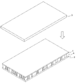
- FIG. 1A is a perspective view of a paper board of the present invention.
- FIG. 1B is a front view of the paper board of the present invention.
- FIG. 2A is a perspective view showing a state in which a part of the first paper layer and the third paper layer of the paper board of the present invention is removed to expose the surface of the core.
- FIG. 2B is a perspective view of the paper board of the present invention with a portion of the first paper layer and the third paper layer removed to expose an alternative core surface.
- FIG. 3A shows a process of providing a paper laminate in the process of manufacturing the paper board of the present invention.
- FIG. 3B shows a cutting process of the paper laminate and a core forming process in the manufacturing process of the paper board of the present invention.
- FIG. 3C shows the sandwich-like bonding process of the core with the first paper layer and the second paper layer in the manufacturing process of the paper board of the present invention.
- FIG. 3D shows an adhesion process of the paper layer 3 to the paper layer 1 in the manufacturing process of the paper board of the present invention.
- FIG. 4 is a schematic diagram showing a bending test in Examples.
- FIG. 5A shows the appearance of the core component according to a preferred cutting method.
- FIG. 5B shows a state of cutting the core constituent member according to a preferable cutting method.
- FIG. 5C shows the state after cutting of the core component according to a preferred cutting method.
- FIG. 6A shows the state of adhesion between the cut surface of the core component and the liner layer according to a preferred cutting method.
- FIG. 6B shows an adhesion state between the cut surface of the core member and the liner layer according to a general cutting method.
- FIG. 7A shows an example of a cutting blade that can be used in a preferred cutting method.
- FIG. 7B shows an example of a cutting blade that can be used in a preferred cutting method.
- FIG. 7C is a side view showing an example of a general cutting blade.
- FIG. 7D is a perspective view showing an example of a general cutting blade.
- FIG. 8A is a schematic diagram showing the cutting of the core component by a preferred cutting method.
- FIG. 8B is a schematic diagram showing the cutting of the core constituent member by a general cutting blade.
- FIG. 9A shows the state of the cut surface of the core component according to a preferred cutting method.
- FIG. 9B shows a state of a cut surface of a core constituent member that is an object to be cut by a general cutting blade.
- FIG. 10A is a bottom perspective view of the four-way pallet of the present invention.
- FIG. 10B is a bottom view of the four-way pallet of the present invention.
- FIG. 10C is a front view of the four-way pallet of the present invention with the bottom side facing up.
- FIG. 10D is a side view of the four-way pallet of the present invention with the bottom side facing up.
- FIG. 11A is a bottom perspective view of a conventional four-way pallet.
- FIG. 11B is a bottom view of a conventional four-way pallet.
- FIG. 11C is a front view of a conventional four-way pallet with the bottom side facing up.
- FIG. 11A is a bottom perspective view of a conventional four-way pallet.
- FIG. 11B is a bottom view of a conventional four-way pallet.
- FIG. 11C is a front view of
- 11D is a side view of a conventional four-way pallet with the bottom side facing up.
- 12A to 12C are diagrams showing a typical method for manufacturing the four-way pallet of the present invention.
- 12A to 12C are diagrams showing a typical method for manufacturing the four-way pallet of the present invention.
- 12A to 12C are diagrams showing a typical method for manufacturing the four-way pallet of the present invention.
- FIG. 13A shows the dimensions of the pallets of Examples 8 and 9 (unit is mm).
- FIG. 13B shows the dimensions of the pallet of the comparative example (unit is mm).
- the two board layers sandwiching the core of the paper board in a sandwich-like manner are bonded with an additional paperboard layer only on one side, and only the paper layer on one side of the core is made thicker.
- the overall bending strength can be effectively increased to a level comparable to that of wood boards.
- this additional paperboard layer inexpensive paper such as used paper and recycled paper can be used, so that a paper board having strong bending strength can be manufactured at low cost.
- high strength can be achieved without increasing the thickness of the paper board.
- a bending strength that could not be achieved in the past can be achieved by simply bonding a paperboard layer of about 1 mm to 4 mm to a core sandwiched between two liner paper layers having a thickness of about 15 mm to 40 mm.
- the present inventor has unexpectedly realized a paper board that can withstand a load of 400 kg or more, which could not be achieved by the present invention, with a board thickness of, for example, about 15 to 20 mm.
- the bending strength of the paper board structure can be increased greatly without increasing the cost. More specifically, among the two paper layers sandwiching the core of the paper board structure in a sandwich-like manner, the basis weight of the paper layer to which the additional paper layer is bonded is more than the basis weight of the other paper layer. By making it small, the bending strength of the whole board structure can be increased greatly. Actually, since one of the two paper layers sandwiching the core in a sandwich-like manner can be used, it can be manufactured at a low cost because a paper having a bending strength of about a temporary fastening can be used.
- a paper four-way pallet having a first direction and a second direction orthogonal to the first direction, the plurality of first bottom plates extending in the first direction
- a plurality of second bottom plates that extend in the second direction and are bonded to the first bottom plate, and a portion where the first bottom plate and the second bottom plate intersect with each other.
- a pallet comprising a plurality of bonded legs and an upper plate bonded to the plurality of legs is provided.
- the lower plate is formed by the first elongated bottom plate and the second elongated bottom plate, the lower plate is compared with the conventional pallet in which the lower plate is formed by a single sheet of paper. Paper waste can be reduced in forming.
- a special device is required for the work of punching and forming the opening for the handlift wheel on a piece of paper, which is costly. In the present invention, such work is not necessary. Therefore, cost can be suppressed.
- the first bottom plate is grounded, and the second bottom plate is not grounded.
- the grounding surface of a pallet can be reduced and the water
- a sufficient space from the ground to the second bottom plate can be secured by increasing the thickness of the first bottom plate.
- the basis weight of the first bottom plate is larger than that of the second bottom plate, so that the reinforcement of the entire pallet can be efficiently achieved.
- a plurality of elongate paper pieces in the vertical direction of the pallet and a plurality of elongate paper pieces in the horizontal direction are crossed so as to be orthogonal to each other to form a lower plate, thereby causing either the vertical direction or the horizontal direction.
- the strength against peeling of the legs is improved.
- the paper pallet there is a problem that when the force is applied partially (one or a few of the plurality of legs), the legs are peeled off.
- This problem can also be solved by forming a lower plate by intersecting a plurality of elongated paper pieces in the vertical direction and a plurality of elongated paper pieces in the horizontal direction so as to be orthogonal to each other as in the pallet of the present invention.
- paper is used in its general meaning, and refers to any substance in which plant fibers are dispersed in water and thinly spread on a flat surface and dehydrated and dried.
- core refers to any structure that provides bending strength to a paper board structure.
- corrugated cardboard is a paper member in which a liner is bonded to one or both sides of a corrugated core paper, and the space formed by the core paper and the liner is the plane of the liner. The one that extends in the direction.
- “Corrugated cardboard” includes a single-sided cardboard with a liner bonded to one side of a core paper, a double-sided cardboard with a liner attached to the top of a single-sided cardboard core, and a single-sided cardboard core on one side. Examples thereof include, but are not limited to, a combined double-sided cardboard and a double-sided cardboard in which a core portion of a single-sided cardboard is further bonded to one side of the double-sided cardboard.
- the “horizontal eye” of the cardboard means a direction substantially parallel to the direction in which the space formed by the core paper of the cardboard and the liner extends
- the “longitudinal” of the cardboard means the core of the cardboard.
- the “board-like structure” is a structure formed by sandwiching a core between two liner paper layers in a sandwich-like manner, and is formed by the core and two liner paper layers.
- the structure in which the space to be extended extends in the thickness direction of the structure. Therefore, it should be noted that the board-like structure in the present invention is clearly different from the cardboard in which the space formed by the core paper and the liner extends in the planar direction of the liner.
- paper board refers to a paper structure in which an additional paperboard layer is provided on the board-like structure.
- Basis weight refers to the weight per 1 m 2 of paper.
- winding is possible means that a paper winder can roll onto a core having a diameter of about 110 mm.
- the “rollable” paper in the present invention may be a general web that is rolled and distributed as a product. More specifically, the “rollable” paper in the present invention may be paper that can be wound into a roll having a thickness of about 1.2 mm or less.
- non-rollable paper in the present invention may be a general lithographic paper distributed as a product in a sheet form. More specifically, the “non-rollable” paper in the present invention may be paper having a thickness of about 1.0 mm or more and cannot be wound into a roll.
- liner paper layer or “liner paper” refers to a paper layer sandwiching a core like a sandwich.
- the liner paper layer in this specification does not contain substantial space inside. Accordingly, the liner paper layer herein does not include cardboard.
- the liner paper layer refers to paper of about 0.5 mm to about 1.2 mm. In a preferred embodiment, the liner paper layer refers to about 0.5 mm to about 1.2 mm of paper that can be wound.
- paperboard layer or “paperboard” refers to a paper layer added to a board formed by sandwiching a core between at least two liner paper layers.
- the paperboard layer in this specification does not include substantial space inside. Accordingly, the paperboard layer herein does not include cardboard. In one embodiment, it refers to about 1 mm to about 4 mm of paper. In a preferred embodiment, the paperboard layer refers to about 1 mm to about 4 mm of paper that cannot be wound.
- the “bending strength” of a board is a value (Kg / m) obtained by converting a measured value measured by a single point concentrated load of 400 mm span at a speed of 10 mm / min into an evenly distributed load converted to 1 m width.
- This distance of 400 mm is a general distance between the two arms of the forklift. Note that the conversion from the single point concentrated load to the uniformly distributed load is achieved by doubling the measured value of the single point concentrated load.
- shoulder portion refers to a region where the fiber density is changed from before cutting by cutting, which is formed on the cut surface of paper cut by a cutting blade having a wedge-shaped cutting edge. On the cut surface of the paper cut by the wedge-shaped cutting edge of the cutting blade, the fibers spread, the fiber density decreases, and the area increases.
- “pallet” means a cargo bed used for transportation or logistics.
- four-way insertion means that a forklift or handlift arm can be inserted from all four directions in a square or rectangular pallet.
- a pallet in which a forklift or handlift arm can be inserted only from two opposite directions is referred to as a “two-way” pallet.
- fiber density of paper refers to the amount of fibers per volume. Therefore, a high fiber density in a certain region means that the fibers are densely present in the region, and conversely a low fiber density in a certain region means that the fibers are loosely dispersed in the region. It means that it exists.
- the “fiber density of the cut surface” refers to the fiber density of the surface newly generated by cutting the paper member and the vicinity of the region where the fiber density of the paper has changed by cutting. It should be noted that the fiber density of the cut surface is not necessarily limited to the fiber density of the surface alone.
- the area of the cut surface refers to the area of the surface newly generated by cutting the paper member.
- the “imaginary corresponding surface” before cutting refers to a virtual cross section of the paper member before cutting at the position of the surface generated by cutting the paper member.
- substantially plane does not mean a complete plane but may include some curvature.
- the paper board 10 of the present invention has three paper layers (first liner).
- a board composed of a paper layer 1, a second liner paper layer 2 and a third paperboard layer 3) and a core 4.
- the liner paper layer 1 and the liner paper layer 2 and the core 4 are bonded to each other so that the liner paper layer 1 and the liner paper layer 2 sandwich the core 4 in a sandwich manner.
- the third paperboard layer 3 is bonded to the surface of the liner paper layer 1 (the surface opposite to the bonding surface with the core 4).
- the sandwich-like adhesion of the liner paper layer 1 and the liner paper layer 2 to the core 4 is obtained by winding the liner paper layer 1 into a roll.
- the liner paper layer 1 is fed out from the roll body, and the liner paper layer 2 is fed out from the other roll body obtained by winding the liner paper layer 2 into a roll, and the liner paper layer 1 is adhered to one surface of the core 4. And it can be performed by adhering the liner paper layer 2 to the other surface of the core 4. Therefore, in this embodiment, both the liner paper layer 1 and the liner paper layer 2 must be rewound paper products.
- the features of the present invention are comparable to a timber board by further reinforcing the structure in which the core 4 is sandwiched between the liner paper layer 1 and the liner paper layer 2 with the paperboard layer 3. It is in the point which can raise the bending strength of a board to such an extent. More specifically, for example, when the paperboard layer 3 is bonded to the liner paper layer 1, the sum of the basis weight of the liner paper layer 1 and the basis weight of the paperboard layer 3 is larger than the basis weight of the liner paper layer 2. Thus, each paper layer is selected. As this additional paperboard layer 3, inexpensive paper such as used paper or recycled paper can be used, so that the cost does not increase.
- the feature of the present invention is that the structure in which the core 4 is sandwiched between the liner paper layers 1 and 2 is further reinforced by the paperboard layer 3 without increasing the overall thickness of the board. It exists in the point which can raise bending strength efficiently. Therefore, the paper board of the present invention can realize a high load capacity and / or a high load resistance without the board itself having a large volume. Further, in the paper board of the present invention, no corrugated cardboard is used for either the liner paper layer or the paperboard layer, so there is no variation in direction in the bending strength of the board and / or the decrease in bending strength due to humidity is small. .
- the paper board of the present invention is suitable for use on pallets, molds, and the like, and is particularly suitable for use on pallets where an increase in the thickness of the board itself is directly linked to transportation costs.
- the liner paper layer 1 is thinner than the liner paper layer 2, but the present invention is not limited to this, and the liner paper layer 1 is not limited thereto.
- the liner paper layer 2 may have the same thickness, or the liner paper layer 1 may be thicker than the liner paper layer 2.
- a further feature of the present invention is that a paper having a basis weight smaller than the basis weight of the liner paper layer 2 (preferably a web) is used as the liner paper layer 1.
- the present inventors enhance the overall bending strength of the paper board 10 by reinforcing the structure in which the core is sandwiched between two paper layers with an additional paperboard layer 3.
- the basis weight of the liner paper layer 1 is not the same as the basis weight of the liner paper layer 2 but rather is made smaller so that the paper board 10 is bonded by bonding the paperboard layer 3. It was unexpectedly found that the bending strength was dramatically improved (see particularly Table 2 in the following examples).
- a paper having a small basis weight may be used as the liner paper layer 1, the cost can be reduced as compared with a case where a paper having a basis weight similar to that of the liner paper layer 2 is used. In this field, generally, the smaller the basis weight, the cheaper the paper. Actually, since a paper having a basis weight of about a temporary fixing can be used as the liner paper layer 1, it can be manufactured at low cost. Usually, in order to increase the bending strength of the paper board 10, there is no reason to increase or decrease the basis weight between the liner paper layer 1 and the liner paper layer 2, and those skilled in the art will naturally understand the liner paper. The basis weight of layer 1 and liner paper layer 2 should be comparable. Therefore, the inventors' discovery was completely unexpected. Further, by using a paper having a small basis weight and / or a thin paper as the liner paper layer 1, it is possible to increase the production speed of the board structure and to improve the productivity.
- the liner paper layer 1 Under the condition that the sum of the basis weight of the liner paper layer 1 and the basis weight of the paperboard layer 3 is larger than the basis weight of the liner paper layer 2, the liner paper layer 1 has an arbitrary thickness depending on the application. The thing of a weight and a basic weight can be selected. In a preferred embodiment, the basis weight of the liner paper layer 1 is less than the basis weight of the liner paper layer 2. For example, the basis weight of the liner paper layer 1 is about 210 g / m 2 to about 900 g / m 2 , preferably about 500 g / m 2 to about 700 g / m 2 . In general, when the paper layer is made of the same material, the basis weight of the paper layer depends on the thickness.
- the thickness of the liner paper layer 1 can be thinner than the thickness of the liner paper layer 2.
- paper products have a large volume with respect to weight, and the ratio of transportation costs to the product unit price is large. Therefore, by using thin paper as the liner paper layer 1, the thickness (volume) of the paper board is further reduced. Thus, transportation costs can be reduced.
- the thickness of the liner paper layer 1 is, for example, about 0.3 mm to about 1.2 mm, more preferably about 0.7 mm to about 1.2 mm, and preferably about 0.7 mm to about 1.0 mm.
- the liner paper layer 1 may be of a strength that is temporary enough to fix the structure of the core 4. Good.
- the liner paper layer 2 has any thickness depending on the application.
- the thing of a weight and a basic weight can be selected.
- the basis weight of the liner paper layer 2 is greater than the basis weight of the liner paper layer 1.
- the basis weight of the liner paper layer 2 is about 210 g / m 2 to about 900 g / m 2 , and preferably about 500 g / m 2 to about 700 g / m 2 .
- the thickness of the liner paper layer 2 is, for example, about 0.3 mm to about 1.2 mm, and preferably about 0.5 mm to about 1.0 mm.
- Both liner paper layer 1 and liner paper layer 2 are preferably rollable web products.
- a core paper typically used as the liner paper layer.
- a paper tube paper typically used as the liner paper layer.
- the paperboard layer 3 is adhered to the surface of the linerpaper layer 1 at the same time as or after the linerpaper layer 1 and the linerpaper layer 2 are adhered to the core 4.
- the bonding of the paperboard layer 3 takes place after the bonding of the liner paper layer 1 and the liner paper layer 2 to the core 4 using a winder. Therefore, the paperboard layer 3 does not need to be a paper that can be wound, and can be a paper that cannot be wound, typically a lithographic paper, or of course a paper that has been cut off. As described above, the paperboard layer 3 may be wound or not, so that a wide variety of papers can be used.
- the thickness of the paperboard layer 3 is about 1 mm to about 4 mm.
- the paperboard layer 3 is, for example, paper for paper tube paper having a thickness of about 1 mm (typical basis weight 700 g / m 2 ) or paper obtained by bonding 2 to 4 sheets thereof. When four sheets of paper having a basis weight of 700 g / m 2 are bonded, the basis weight is about 3,150 g / m 2 including the weight of the paste for bonding.
- the paper layer 3 may be composed of a single layer of paper, or may be composed of a plurality of layers of paper.
- the thickness of the board-like structure (liner paper layers 1, 2 and core 4) of the present invention is about 15 mm to about 40 mm, more preferably about 15 mm to about 30 mm, and more preferably about 20 mm to about 30 mm. It is.
- the inventor of the present invention can greatly increase the bending strength without greatly increasing the thickness of the entire board by additionally providing a board-like layer of about 1 mm to about 4 mm to the board-like structure in this range. I found it unexpectedly.
- the basis weight of the layer to which the liner paper layer 1 and the paperboard layer 3 are bonded is larger than the basis weight of the liner paper layer 2.
- the liner paper layer 1 and the liner paper layer 2 are paper of the same thickness and / or basis weight.
- the paper board 10 of the present invention may be used with the paperboard layer 3 facing up, or may be used with the paperboard layer 3 facing down.
- a load is applied to the paperboard layer 3 side of the paper board 10
- a compression force is applied to the paperboard layer 3 side and a tensile force is applied to the opposite liner paper layer 2 side, but the liner paper layer 1 and the paperboard layer 3 are compressed.
- the paper board 10 is given a strong bending strength.
- a load is applied to the liner paper layer 2 side of the paper board 10
- a compression force is applied to the liner paper layer 2 side and a tensile force is applied to the opposite paperboard layer 3 side.
- the paper board 10 is also given a strong bending strength.
- the paper board of the present invention is used as a transportation pallet.
- the object to be transported may be supported on the liner paper layer 2 side or on the paperboard layer 3 side.
- the object to be transported may be supported on the liner paper layer 2 side or on the paperboard layer 3 side.
- it is preferable to support the object with the paperboard layer 3 side up In particular, when a forklift is used to load an object that loads an almost entire surface of a paper board with an average, the bending load applies a compressive force to the lower side, so the liner with the paperboard layer 3 side down.
- the object is preferably supported by the paper layer 2.
- the paper board structure of the present invention is used as a transportation pallet, by making the paperboard layer 3 on the lower side (side held by the forklift claw), the transportation board having a desired bending strength can be efficiently obtained. It can be a pallet.
- the required conditions are different between the upper side and the lower side of the board as in the pallet, the required condition can be achieved efficiently by reinforcing one side as in the paper board of the present invention. Can do.
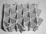
- FIG. 2A and 2B show a specific structure of the core 4 used in the paper board 10 of the present invention.
- FIG. 2A is a perspective view showing a state in which a part of the liner paper layer and the paperboard layer of the paper board of the present invention is removed to expose the surface of the core.
- the most preferred core structure of the present invention is shown in FIG. 2A.
- the core 4 is a core unit composed of a paper core 21 shaped so that a large number of, for example, sinusoidal waveforms are arranged, and a paper liner 22 joined to the curved convex portion on one side thereof. It is formed by arranging a plurality of stages 23 into a flat shape.
- the shape of the core material 21 may be V-shaped, U-shaped, or trapezoidal in addition to the waveform as described above.
- the core 4 may be a honeycomb-shaped core in which a large number of hexagonal column spaces 24 are formed.
- the height H of the core 4 can be appropriately determined by those skilled in the art depending on the use of the paper board 10, but typically, the thickness of the board-like structure is about 15 to about 40 mm. Typically about 20 mm, about 30 mm, or about 40 mm.
- the basis weight of the paper forming the core 4 can be appropriately determined by those skilled in the art depending on the application, and is, for example, about 160 g / m 2 to about 280 g / m 2 .
- FIG. 3 a typical manufacturing method of the paper board 10 will be described.
- a paper laminate 40 having a height higher than the final height 4 of the core 4 is produced (FIG. 3A).
- the laminated body 40 is cut at a thickness of H to form a core 4 (FIG. 3B), and the core 4 is sandwiched between liner paper layers 1 and 2 and bonded (FIG. 3C).
- the paperboard layer 3 is adhered to the surface of the liner paper layer 1 (FIG. 3D) to obtain the paper board 10 of the present invention.
- the paper board 10 can have any size depending on the application, and examples thereof include 1,100 mm ⁇ 1,100 mm, 800 mm ⁇ 1,000 mm, 1,000 mm ⁇ 1,200 mm, and the like. It is not limited.
- the paper board 10 may be formed into a desired size after the core 4 is sandwiched between the liner paper layers 1 and 2 and before the paperboard layer 3 is bonded (ie, in the state shown in FIG. 3C). It may be performed after the paperboard layer 3 is bonded to the liner paper layer 1 (that is, in the state shown in FIG. 3D).
- the adhesive for adhesion may be any paper adhesive.
- a typical corrugated adhesive is a starch adhesive, and contains starch, alkali (for example, caustic soda), boron compound (for example, borax), water, and the like as components.
- the present invention provides a paper-made board-like structure having a bending strength comparable to that of a timber board, the bending strength of which is reinforced by reinforcement with the paper layer 3. Since the paperboard layer 3 can be selected from a wide variety of papers (for example, used paper), inexpensive paper can be used. Therefore, the cost is not increased significantly by the reinforcement with the paperboard layer 3. Furthermore, the paper board structure finally obtained has a strength comparable to that of a wood board, but is made of paper, so that it can be completely recycled after use and contributes greatly to environmental problems.
- the strength of the paper board structure can be freely adjusted according to the use and the predetermined strength.
- the strength of the paper board has been adjusted by changing the structure of the core 4 and the strength of the liner paper layers 1 and 2, particularly by mainly changing the original size of the core.
- changing the structure of the core 4 and the strength of the liner paper layers 1 and 2 requires changing each device and its setting in the automatic production line each time. This is time-consuming and causes a loss every time it is changed, which is a heavy burden on the manufacturer.
- the strength can be freely adjusted simply by changing the type of the paperboard layer 3 to be bonded to the liner paper layer 1, so that various devices in the production line and their settings are changed according to the strength. There is no need to do.
- manufacturers can manufacture paper boards with various strengths without having to change the equipment and settings of the production line for each paper board strength.
- a plurality of types of used paper are prepared as the paperboard layer 3, and an appropriate used paper having a basis weight or a thickness capable of achieving a desired bending strength is selected from among them, and sandwiched between liner paper layers 1 and 2.
- inexpensive paper can be used as the liner paper layer 1 by using a paper having a small basis weight as the liner paper layer 1. Further, by using a paper having a small basis weight and / or a thin paper as the liner paper layer 1, it is possible to increase the production speed of the board structure and to improve the productivity.
- the present invention is typically characterized by greatly increasing the bending strength without greatly increasing the thickness of the board.
- a bending strength of, for example, 1000 kg / m is required
- a board-like structure of 60 mm in the case of the board-like structure of Table 4 with 60 mm and no paperboard
- Bend strength of 1144 kg / m or two board-like structures are stacked and bonded together (for example, two 30 mm board-like structures are bonded together, or a 20 mm board-like structure and A paper board having a strength capable of withstanding such a weight load is provided by bonding to a 30 mm board-like structure.
- a bending strength of 1298 kg / m is achieved by adhering 1 mm paperboard to a 30 mm boardlike structure (see the case of 30 mm boardlike structure and 1 mm paperboard in Table 4). The bending strength of 1000 kg can be achieved while the board is 31 mm thick.
- a thickness of 60 mm is currently required, whereas the present invention achieves the same or higher strength with about half that thickness.
- the bending strength achieved in the past by bonding two board-like structures having a thickness of 40 mm to 60 mm, or two board-like structures having a thickness of 30 mm is 1 to 1 for a board-like structure having a thickness of 30 mm. This can be achieved only by combining about 4 mm paperboard.
- the thickness of the board-like structure is about 15-40 mm and the thickness of the additional paperboard layer is about 1 mm to about 4 mm. In a preferred embodiment, the thickness of the paperboard layer is from about 1 mm to about 3 mm, and in a more preferred embodiment, the thickness of the paperboard layer is from about 1 mm to about 2 mm.
- the present invention achieves a bending strength of 450 kg / m with a small thickness compared to the prior art.
- the present invention relates to a paper board in which a board of about 1 mm to 4 mm is bonded to a board-like structure of about 15 mm to less than 20 mm, and has a bending strength of about 450 kg / m or more. I will provide a.
- the present invention is a paper board in which a board of about 1 mm to about 4 mm is bonded to a board-like structure of about 15 mm or more and less than 20 mm, and the bending strength is about 500 kg / m or more.
- the present invention is a paper board in which a board of about 1 mm to about 4 mm is bonded to a board-like structure of about 15 mm or more and less than 20 mm, and the bending strength is about 550 kg / m or more.
- a board having a bending strength of 550 kg / m can sufficiently withstand a load of 400 kg.
- the present invention achieves a bending strength of 650 kg / m with a small thickness compared to the prior art.
- the present invention is a paper board in which a board of about 1 mm to 4 mm is bonded to a board-like structure of about 20 mm or more and less than 30 mm, and has a bending strength of about 650 kg / m or more. I will provide a.
- the present invention is a paper board in which a board of about 1 mm to about 4 mm is bonded to a board-like structure of about 20 mm or more and less than 30 mm, and the bending strength is about 700 kg / m or more.
- the present invention is a paper board in which a board of about 1 mm to about 4 mm is bonded to a board-like structure of about 20 mm or more and less than 30 mm, and the bending strength is about 750 kg / m or more.
- a board having a bending strength of 700 kg / m can sufficiently withstand a load of 500 kg.
- the present invention achieves a bending strength of 950 kg / m with a small thickness compared to the prior art.
- the present invention relates to a paper board in which a board of about 1 mm to 4 mm is bonded to a board-like structure of about 30 mm to 40 mm, and has a bending strength of about 950 kg / m or more. I will provide a.
- the present invention is a paper board in which a board of about 1 mm to about 4 mm is bonded to a board-like structure of about 30 mm to 40 mm, and the bending strength is about 1000 kg / m or more.
- the present invention is a paper board in which a board of about 1 mm to about 4 mm is bonded to a board-like structure of about 30 mm to 40 mm, and the bending strength is about 1100 kg / m or more.
- Provide paper board for example, according to the present inventor's research and development, a board having a bending strength of 950 kg / m can sufficiently withstand a load of 700 kg.
- the present invention achieves a bending strength of 950 kg / m with a small thickness compared to the prior art.
- the present invention relates to a paper board in which a board of about 1 mm to 4 mm is bonded to a board-like structure of about 30 mm to less than 40 mm, and has a bending strength of about 950 kg / m or more. I will provide a.
- the present invention is a paper board in which a board of about 1 mm to about 4 mm is bonded to a board-like structure of about 30 mm or more and less than 40 mm, and the bending strength is about 1000 kg / m or more.
- the present invention is a paper board in which a board of about 1 mm to about 4 mm is bonded to a board-like structure of about 30 mm or more and less than 40 mm, and the bending strength is about 1100 kg / m or more.
- a board of about 1 mm to about 4 mm is bonded to a board-like structure of about 30 mm or more and less than 40 mm, and the bending strength is about 1100 kg / m or more.
- the thickness of the additional paperboard layer is no more than about 20% of the thickness of the board-like structure. In a more preferred embodiment, the thickness of the additional paperboard layer is no more than about 15% of the thickness of the board-like structure. In a further preferred embodiment, the thickness of the additional paperboard layer is no more than about 10% of the thickness of the board-like structure. In a further preferred embodiment, the thickness of the additional paperboard layer is no more than about 5% of the thickness of the board-like structure.
- the paper board of the present invention can be used in place of wood board in various applications where wood board is used.
- Examples of the use of the paper board of the present invention include, but are not limited to, pallets and molds.
- the paper board of the present invention is particularly suitable for use on a transportation pallet.
- paper products have a large volume with respect to weight, and the ratio of transportation costs to the product unit price is large. Therefore, reducing the thickness (volume) of paper boards directly leads to a reduction in transportation costs. .
- the paper board of the present invention has a variation in bending strength due to a structurally inevitable direction when using cardboard.
- a high bending strength can be achieved in any direction and / or a decrease in bending strength due to humidity is small.
- the paper board of the present invention is suitable for use on a transportation pallet.
- waterproofing method a method of coating the resin film on the board surface by degassing the air in the bag with the board inserted into a bag-like resin film (for example, vinyl) is preferable.
- a paper board may be dipped in a water-resistant or water-repellent liquid such as paraffin wax or phenol resin to coat the surface.
- the method of coating the surface of the paper board by degassing the bag-shaped resin film to form a mold is coated with the resin film firmly attached to the surface of the mold, so that the strength of the paper board and The rigidity can be improved. Furthermore, the mold can be peeled off very easily from the cured concrete product with little force.
- Adhesion For adhesion between the core 4 and the liner paper layers 1 and 2, for example, an adhesion technique described in Japanese Patent Application No. 2015-43646 (the contents of which are incorporated herein by reference) can be used.
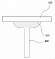
- the core constituent member 400 is a piece of paper that forms the corrugation of the core 4.
- the core component member 400 is cut along the alternate long and short dash line C by the cutting blade 80 and adhered to the liner paper layers 1 and 2 along the cut surface at a substantially right angle.
- the wedge-shaped cutting edge of the cutting blade 80 is inserted into the core component member 400 that is the object to be cut, and as the cutting blade 80 is advanced, the core component member 400 is pushed and spread on both sides of the cutting edge to form the cutting surface 410. (See FIG. 5B and FIG. 5C.
- the core constituent member 400 in the vicinity of the cutting surface 410 is less likely to become paper dust when cut by the cutting blade, and still remains in the core constituent member 400 after cutting.
- the cut surface 410 the fibers constituting the core constituent member 400 spread, the fiber density decreases, and the area increases (a “shoulder portion” is formed).
- the cut surface 410 does not indicate only a surface generated in the core component member 400 by cutting, but indicates a region where the fiber density has changed from before cutting by cutting.
- the cross section of the core component member 400 (that is, the vertical cross section including the alternate long and short dash line C) when it is assumed that the core member 400 is clearly cut along the alternate long and short dash line C is the “virtual corresponding surface before cutting” in the present invention. It is clearly understood that the area of the bonding surface 410 is larger than the virtual corresponding surface before cutting.
- FIG. 6A another paper member 420 (specifically, liner paper layer 1 or 2) is formed on the cut surface 410 of the core constituent member 400 obtained by cutting with the cutting blade 80 as shown in FIGS. 5A to 5C. A state of bonding is shown.
- the cutting surface 410 of the core component member 400 can secure a larger and larger bonding surface than the virtual corresponding surface before cutting by cutting with the cutting blade 80.
- the fiber density of the cut surface 410 is smaller than the fiber density of the core constituent member 400 before cutting, the adhesive easily penetrates and is easily entangled. Thereby, coupled with the fact that the area of the cut surface 410 of the core constituent member 400 is larger than the virtual corresponding surface before cutting, high adhesive strength is realized.
- FIG. 6B shows a state in which the core constituent member 400 cut by a general cutting blade and another paper member 420 are bonded to the cut surface.
- the cut surface of the core component 400 cut by a general cutting blade has a small adhesive surface, and the fiber density does not change in the cut surface and the core component 400 in the vicinity thereof.
- the adhesive is not easy to penetrate through the cut surface. Therefore, compared with the cut surface of the core component member 400 cut by the wedge-shaped cutting blade of the preferred embodiment, the adhesive force with another paper member 420 is weak.
- FIGS. 7A and 7B show a cutting blade for the above preferred bonding method
- FIGS. 7C and 7D show a cutting blade for a general bonding method
- the cutting blade (clean cut saw) shown in FIGS. 7A and 7B has a wedge-shaped tip, and the cutting edge is inserted into the workpiece, and as the cutting blade advances, the workpiece is pushed and spread on both sides of the cutting edge. Go.
- the general cutting blades (tip saws) shown in FIGS. 7C and 7D are formed by arranging a tip having a blade tip inclined to the left and right sides and a flat tip. Cut the object to be cut. Therefore, in the cutting with the cutting blades of FIGS.
- the paper is cut without changing the paper into paper dust by separating while cutting the cut portion.
- 7C and 7D the cut portion of the object to be cut is scraped off and converted into paper dust and removed.
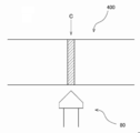
- FIG. 8A and FIG. 8B show schematic diagrams of cutting by a preferable cutting method and cutting by a general cutting method.
- FIG. 8A shows a state in which the core constituent member 400 is cut along the C with the cutting blade 80 according to the present invention.
- the wedge-shaped cutting blade 80 cuts the hatched portion of the core component member 400 along C while pushing it left and right. It will be understood that as the cutting edge of the cutting blade 80 is inserted into the workpiece and the cutting blade advances, the workpiece is pushed and spread on both sides of the cutting edge.
- FIG. 8B shows a state in which the core constituent member 400 is cut along the C with a general cutting blade 80 ′.
- the cutting blade 80 ′ is formed by arranging chips that are inclined to the left and right outwards and flat chips, and cuts the object to be cut while scraping the chip width (the hatched portion in FIG. 8B) to change it into paper dust. It will be understood. Note that the width of the cut (shaded portions in FIGS. 8A and 8B, respectively) is larger in FIG. 8B.
- FIG. 9A shows the state of the cut surface of the member that is the object to be cut by the above preferred cutting method
- FIG. 9B shows the state of the cut surface of the member that is the object to be cut by a general cutting method.
- the photographs shown in FIGS. 9A and 9B are the results of cutting the same member with different cutting blades.
- the cutting with the cutting blade (clean cut saw) shown in FIGS. 7A and 7B is more effective than the cutting with the general cutting blade (tip saw) shown in FIGS. 7C and 7D. It can be seen that the fibers spread on the surface, the fiber density is reduced, and the area is increased.
- the fiber density of the cut surface 410 of the core constituent member 400 is smaller than the fiber density of the core constituent member 400 before cutting by cutting with a cutting blade (clean cut saw) shown in FIGS. Can easily penetrate and the adhesive is easily entangled with the fiber, and high adhesive strength can be realized. Furthermore, since the cutting surface 410 of the core constituent member 400 becomes larger than the virtual corresponding surface before cutting of the core constituent member 400 by cutting, a wide adhesive surface can be secured and high adhesive strength can be realized.
- Adhesion using a preferable wedge-shaped cutting blade can achieve adhesion with high adhesive strength in the vertical direction between the core 4 and the liner layer 1 and / or 2.
- a large load is also applied to the connecting portion between the core and the liner paper layer.
- the connection is stabilized, thereby achieving high bending strength of the entire board (see Example 7).
- FIG. 10A is a bottom perspective view of the four-way pallet 100 of the present invention
- FIG. 10B is a bottom view thereof
- FIG. 10C is a front view with the bottom side up
- FIG. It is the side view which made the bottom side the upper side.
- the four-way pallet of the present invention has a plurality of first bottom plates 200 extending in the first direction of the pallet (longitudinal direction in FIG. 10A) and orthogonal to the bottom as seen from the bottom surface side.
- a plurality of second bottom plates 300 that extend in the second direction (short direction in FIG.
- first bottom plate 200 forms the ground plane of the pallet.
- FIGS. 10A and 10C the pallet of the embodiment in which the first bottom plate 200 is thicker than the second bottom plate 300 is shown, but the present invention is not limited to this embodiment.
- Embodiments in which the thickness of the second bottom plate 300 is larger than that of the first bottom plate 200 and embodiments in which the thicknesses of the first bottom plate 200 and the second bottom plate 300 are equivalent are also included in the present invention.
- 10A and 10C show the pallet of the embodiment in which the second bottom plate 300 extends in the short direction, but the present invention is not limited to this embodiment, and the second bottom plate It should be noted that 300 extends in the longitudinal direction, and embodiments in which the first bottom plate 200 extends in the lateral direction are also encompassed by the present invention.
- FIG. 11A is a bottom perspective view of a prior art four-way pallet 100
- FIG. 11B is a bottom view thereof
- FIG. 11C is a front view with the bottom side up
- FIG. It is the side view which made the bottom side the upper side.
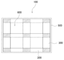
- the bottom plate 130 is formed of a single sheet of paper when viewed from the bottom side, and the opening 600 is formed by punching out the bottom plate 130.
- the leg portion 140 is bonded to the bottom plate 130, and the upper plate 150 is further bonded thereto.
- Each of the first bottom plate 200 and the second bottom plate 300 is an elongated rectangular paper piece.
- the first bottom plate 200 and the second bottom plate 300 may be formed from the same paper or different papers.
- the first bottom plate 200 for example, a piece of paper of about 86 mm to 200 mm ⁇ about 700 mm to 1400 mm is used, and typically a piece of paper of about 86 mm ⁇ about 1110 mm can be used.
- the size of the first bottom plate 200 can be appropriately determined by those skilled in the art according to the size and strength of the entire pallet, the size of the forklift or handlift arm used, the size of the wheel of the handlift, or the like. it can.
- first bottom plates 200 are used.
- the distance between adjacent first bottom plates 200 is about 180 mm to about 400 mm, typically about 251 mm.
- the thickness of the first bottom plate 200 is about 1 mm to about 6 mm, preferably about 2 mm to about 4 mm, and more preferably about 4 mm.
- the second bottom plate 300 for example, a paper piece of about 150 mm to 200 mm ⁇ about 700 mm to 1100 mm is used, and a paper piece of about 170 mm ⁇ about 760 mm can be used typically.
- the size of the second bottom plate 300 can be appropriately determined by those skilled in the art according to the size and strength of the entire pallet, the size of the forklift or handlift arm used, the size of the handlift wheel, and the like. it can.
- a plurality of second bottom plates 300 are used.
- the distance between adjacent second bottom plates 300 is about 180 mm to about 400 mm, typically about 290 mm.
- the thickness of the second bottom plate 300 is about 1 mm to about 6 mm, preferably about 2 mm to about 4 mm, and more preferably about 2 mm.
- the first bottom plate 200 and the second bottom plate 300 may be formed by laminating generally distributed cardboard of about 1 mm to about 3 mm.
- the thickness of the first bottom plate 200 and the thickness of the second bottom plate 300 may be in any relationship. That is, the first bottom plate 200 may be thicker than the second bottom plate 300, or the second bottom plate 300 may be thicker than the first bottom plate 200. Alternatively, the thickness of the first bottom plate 200 and the thickness of the second bottom plate 300 may be equal.
- the first bottom plate 200 is thicker than the second bottom plate 300.
- the first bottom plate 200 is about 4 mm and the second bottom plate 300 is about 2 mm.
- the thickness of the first bottom plate 200 is about 1.5 times or more, more preferably about 2.0 times or more, more preferably about 2 times the thickness of the second bottom plate 300. .5 times or more.
- the basis weight of the second bottom plate 300 is about 600 g / m 2 ⁇ about 3500 g / m 2, preferably about 1400 g / m 2 ⁇ about 3300 g / m 2.
- the basis weight of the first bottom plate 200 and the basis weight of the second bottom plate 300 may be in any relationship. That is, the basis weight of the first bottom plate 200 may be larger than the basis weight of the second bottom plate 300, or the basis weight of the second bottom plate 300 is larger than the basis weight of the first bottom plate 200.
- the basis weight of the first bottom plate 200 and the basis weight of the second bottom plate 300 may be equivalent.
- the first bottom plate 200 When the first bottom plate 200 and the second bottom plate 300 are formed from different papers, the first bottom plate 200 preferably has a larger basis weight than the second bottom plate 300.
- the basis weight of the first bottom plate 200 is about 2400 g / m 2 ⁇ about 3000 g / m 2
- the basis weight of the second bottom plate 300 is about 1200 g / m 2 ⁇ about 1600 g / m 2 .
- the basis weight of the first bottom plate 200 is about 1.5 times or more, more preferably about 2.0 times or more, more preferably about 2 times the basis weight of the second bottom plate 300. .5 times or more.
- both the thickness and basis weight of the first bottom plate 200 are larger than the thickness and basis weight of the second bottom plate 300, respectively.
- the strength of the entire pallet can be efficiently increased.
- the longitudinal dimension of the forklift or handlift outside the claw is larger (the dimension of the part that goes out of the two claws when the two claws of the forklift or handlift are inserted into the pallet). It is.
- the bottom plate of the pallet is formed from a single sheet of paper as in the prior art, it is necessary to increase the thickness and / or basis weight of the entire bottom plate according to the strength required for the sides in the longitudinal direction. there were.
- the first bottom plate 200 extending in the longitudinal direction and the second bottom plate 300 extending in the short direction are combined to form the bottom plate of the prior art, strength is not required.
- the basis weight of the second bottom plate 300 can be reduced, and the basis weight of the first bottom plate 200, which requires more strength, can be increased.
- the process of punching the opening is not easy when the thickness or basis weight of the bottom plate increases. This is because, in a paper having a large thickness or basis weight, the opening cannot be punched with a general apparatus (for example, a rotary die cutter commercially available from various sources).
- a general rotary die cutter can only punch up to about 2 mm thick paper, and for thicker paper (for example, about 3 mm or about 4 mm that is generally distributed) (Platen die cutter) must be used.
- any die cutter has a problem that the cutting blade is damaged quickly.
- the bottom plate of the present invention can be manufactured by simply cutting a large piece of paper in a straight line, and is complicated such as punching an opening. No processing is required. Therefore, it is possible to use paper having a large thickness or basis weight for the bottom plate.
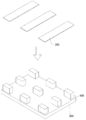
- (Production method) 12A to 12C show a typical method for manufacturing the four-way pallet of the present invention.
- the leg portion 400 is bonded to the upper plate 500.
- the top plate 500 is the paper board structure 10 shown in FIG. 1A and the like.
- the number of legs can be appropriately determined by those skilled in the art depending on the size of the pallet, the application, and the type of forklift or handlift used.
- the second bottom plate 300 is bonded along the short direction to the legs 400 bonded to the upper plate 500 in FIG. 12A.
- the second bottom plate 300 can be easily manufactured by cutting cardboard.
- the first bottom plate 200 is further bonded along the leg 400 to the pallet in which the second bottom plate 300 is bonded to the leg 400 in FIG. 12B.
- the selection of the thickness and basis weight of the first bottom plate 200 is important in the present invention.
- the second bottom plate 300, the leg 400, and the top plate 500 are separated from the ground contact surface by the thickness of the first bottom plate 200. As a result, the moisture on the ground contact surface is prevented from being absorbed by the second bottom plate 300, the leg 400 and the upper plate 500.
- a person skilled in the art can appropriately determine what thickness and / or basis weight of the paper is used as the first bottom plate 20 and the second bottom plate 300.
- the first bottom plate 200 and the second bottom plate 300 can be prepared by cutting cardboard into long and narrow strips. Commonly available cardboard sizes include, but are not limited to, 1100 mm ⁇ 1350 mm or 1150 mm ⁇ 1450 mm.
- the leg 400 is bonded to the upper plate 500
- the second bottom plate 300 is bonded to the leg 400
- the first bottom plate 200 is bonded to the second bottom plate 300.
- the order may be anything.
- the second bottom plate 300 may be bonded to the first bottom plate 200, the leg portion 400 may be bonded to the second bottom plate 300, and the upper plate 500 may be bonded to the leg portion 400.
- the leg 400 may be adhered to the upper plate 500, the second bottom plate 300 may be separately adhered to the first bottom plate 200, and finally the leg 400 and the second bottom plate 300 may be adhered.
- the bonding between the leg 400 and the second bottom plate 300 or the top plate 500 can be performed by any known method, but by the method described in the “bonding” section with reference to FIGS. 5A to 9B. Adhesion is particularly preferred.
- the upper plate of the pallet of the present invention may be any paper as long as it is made of paper, but of course, the pallet has a bending strength that can withstand lifting by a forklift or handlift in a state where an object is placed. Must be granted to
- a structure for example, a paper board structure 10 shown in FIG. 1A
- a reinforcing core structure is sandwiched from above and below by a paper layer
- an object to be transported may be supported on the paper layer 2 side or on the paper layer 3 side.
- the present invention is not limited, it is preferable to support the object with the paper layer 3 side up when transporting an object that intensively loads a part of the upper plate.
- the bending load is applied to the paper layer 2 with the paper layer 3 side down because a compression force is applied to the lower side. It is preferable to support the object.
- a large bending strength is required on the lower side of the pallet upper plate (side held by a forklift or handlift arm). Accordingly, when the paper board structure 10 shown in FIG. 1A is used as a transportation pallet, the desired bending can be efficiently performed by placing the paper layer 3 on the lower side (the side held by a forklift or handlift arm). It is possible to provide a transportation pallet having strength.
- the leg 400 of the present invention may have any shape and structure as long as it is made of paper.
- the leg 400 may be, for example, a rectangular parallelepiped, a cube, or a cylinder.
- the structure of the leg 400 may be the same structure as the core 4 of the paper board structure 10. That is, the core 4 of FIG. 2A and FIG. 2B can be made into an appropriate shape to form the leg portion 400.
- the paper member used for the pallet of the present invention may be waterproof.
- at least the first bottom plate 200 of the paper pallet of the present invention is waterproofed.
- the waterproof first bottom plate 200 can be obtained by cutting the waterproof sheet-like paper into the first bottom plate 200, or cutting the sheet-like paper to obtain the first bottom plate 200. It can also be obtained by making it 200 after waterproofing.
- waterproofing can be performed by applying a water-resistant or water-repellent agent to the surface of the paper, but is not limited thereto.
- a water-resistant agent or water-repellent agent a known water-resistant agent or water-repellent agent for paper can be used, and preferably, a known water-resistant agent or water-repellent agent for cardboard can be used.
- the waterproof first base plate 200 can be manufactured by applying a water-proofing agent or a water-repellent agent to a sheet-like paper and then cutting it to a desired size.
- application of the water-resistant agent or water-repellent agent to the sheet-like paper can be performed using a roller.
- the paper to be subjected to waterproofing can be limited to only a bottom plate that is grounded among a bottom plate extending in the vertical direction and a bottom plate extending in the horizontal direction. As a result, pallets can be manufactured at low cost.
- the bottom plate to be grounded is waterproofed, and other parts such as the upper plate which is the load placement surface are not waterproofed. This can reduce the amount of paper that needs waterproofing and consequently reduce the cost associated with pallet manufacturing. Furthermore, the bottom plate extending in the vertical direction and the bottom plate extending in the horizontal direction can be minimized by using a shorter bottom plate for the grounding surface and applying waterproof processing only to that.
- the basis weight of the liner paper layer 1 is 210 g / m 2 (thickness is about 0.3 mm) and the basis weight of the liner paper layer 2 is 700 g / m 2 (in accordance with the manufacturing method shown in FIGS. 3A to 3D.
- the thickness of the paperboard layer 3 is about 1.0 mm
- the basis weight of the paper used for the core 4 is 220 g / m 2
- the thickness of the board-like structure (core 4, liner paper layers 1 and 2) is 30 mm.
- Example 3 basis weight
- 1 mm about 700 g / m 2 (example 1-1), 2 mm (about 1,400 g / m 2) (example 1-2), and 4 mm (about 2,800 g / m 2) (embodiment Three boards of Example 1-3) were produced.
- an adhesive mainly composed of starch is applied to the adhesive surfaces of the core 4 and the liner paper layer 1 and the liner paper layer 2 of the core 4 unrolled from the roll, the liner paper layer 1 and the liner paper layer 2 are applied. Were stacked on the bonding surface in a sandwich-like manner and pressed to bond both paper layers to the core.
- the paperboard layer 3 was bonded to the liner paper layer 1 using an aqueous vinyl acetate resin (for example, CN-135, Konishi Co., Ltd., Osaka, Japan) adhesive. Also, a board (reference example 1) without the paperboard layer 3 as a reference was manufactured.
- an aqueous vinyl acetate resin for example, CN-135, Konishi Co., Ltd., Osaka, Japan
- Example 2 Similar to Example 1, as Example 2, the basis weight of the liner paper layer 1 is 700 g / m 2 (thickness: about 1.0 mm), and the basis weight of the liner paper layer 2 is 700 g / m 2 (thickness: about 1.0 mm).
- the basis weight of the paper used for the core 4 is 280 g / m 2
- the thickness of the board-like structure is 30 mm
- the thickness of the paperboard layer 3 is 1 mm (about 700 g / m 2 ) (Example 2-1) ) 3 boards of 2 mm (about 1,400 g / m 2 ) (Example 2-2) and 4 mm (about 2,800 g / m 2 ) (Example 2-3) were produced.
- a board (reference example 2) without the paperboard layer 3 as a reference was manufactured.
- Example 3 As in Examples 1 and 2, as Example 3, the basis weight of the liner paper layer 1 is 700 g / m 2 (thickness: about 1.0 mm), and the basis weight of the liner paper layer 2 is 700 g / m 2 (thickness: about 1).
- the basis weight of the paper used for the core 4 is 280 g / m 2
- the thickness of the board-like structure is 40 mm
- the thickness of the paperboard layer 3 is 1 mm (about 700 g / m 2 ) (Example 3) -1)
- Three boards of 2 mm (about 1,400 g / m 2 ) (Example 3-2) and 4 mm (about 2,800 g / m 2 ) (Example 3-3) were produced. Further, a board (reference example 3) in which the paperboard layer 3 was not provided as a reference was manufactured.
- Example 4 As Example 4, the basis weight of the liner paper layer 1 was 700 g / m 2 (thickness: about 1.0 mm), the basis weight of the liner paper layer 2 was 700 g / m 2 (thickness: about 1.0 mm), and the core 4 was used.
- the basis weight of the paper is 280 g / m 2
- the thickness of the board-like structure is 50 mm
- the paperboard layer 3 has a thickness (basis weight) of 1 mm (about 700 g / m 2 ) (Example 4-1), 2 mm (about 1, Three boards of 400 g / m 2 ) (Example 4-2) and 4 mm (about 2,800 g / m 2 ) (Example 4-3) were produced.
- a board (reference example 4) in which the paperboard layer 3 was not provided as a reference was manufactured.
- any of the above boards was 500 mm wide ⁇ 333 mm long.
- a rolled paper was used, and as the paperboard layer 3, a planographic paper was used.
- Examples 1-1 to 1-3 are from Reference Example 1
- Examples 2-1 to 2-3 are from Reference Example 2
- Examples 3-1 to 3-3 are from Reference Example 3.
- Examples 4-1 to 4-3 are the multiples of change in the actual measured bending strength from Reference Example 4.
- the actual measured bending strength of the paper board 10 was remarkably enhanced by bonding the paperboard layer 3 to the liner paper layer 1.
- an increase in bending strength comparable to or exceeding the thickness of the board-like structure can be achieved by simply providing an additional paperboard layer 3 of about 1 mm.
- the present inventor has found that the bending strength of the board can be efficiently increased by sticking the additional paperboard layer 3 without greatly increasing the thickness of the board.
- Examples 1-1 to 1-3 when the basis weight of the paperboard layer 3 is increased, the magnification at which the measured value of the bending strength of the board increases with respect to the reference example 1 is higher than that of the reference example 2.
- Examples 2-1 to 2-3 increase in Examples 3-1 to 3-3 with respect to Reference Example 3 and in Examples 4-1 to 4-3 with respect to Reference Example 4, respectively. It was significantly higher than the magnification. This is because the basis weight of the liner paper layer 1 is made smaller than the basis weight of the liner paper layer 2, and when the paperboard layer 3 is reinforced, the effect of the reinforcement reinforces the bending strength of the whole board very efficiently.
- Example 2-3 when Example 1-3 and Example 2-3 are compared, in Example 2-3, the basis weight of the liner paper layer 1 increases from 210 g / m 2 to 700 g / m 2 , and the core paper Despite the fact that the basis weight is increased from 220 g / m 2 to 280 g / m 2 (the liner paper layer 2, the paperboard layer 3, and the core height are the same under the same conditions), the actual measured bending strength of the board is the example. It should be noted that 1-3 is superior. In Example 1-3, although the paper layer 1 and the core have a basis weight that is weaker than that of Example 2-3, the cost is significantly reduced compared to Example 2-3. The board as a whole had high bending strength. This is a result demonstrating the excellent and remarkable effect of the present invention.
- Example 1-3 lithographic paper having a basis weight of 2,800 g / m 2 was used as the paperboard layer 3, whereas Example In 4-1, the paperboard layer 3 was not provided, but instead the basis weight of the core paper increased from 220 g / m 2 to 280 g / m 2 and the board thickness increased from 30 mm to 50 mm.
- the cost increase due to the core condition change greatly exceeds the cost increase due to the use of a lithographic paper having a basis weight of 2,800 g / m 2 as the paperboard layer 3.
- a wide variety of inexpensive paper such as used waste paper can be used as the lithographic paper of the paperboard layer 3.
- Example 1-3 and Example 4-1 were compared, Example 1-3 had higher bending strength although Example 1-3 was less expensive. . This is also a result demonstrating the outstanding remarkable effect of the present invention.
- the bending strength (Kg / m) of the board used in each example is shown below.
- the weight of each board is a numerical value assumed to be 1 m wide
- the bending strength actual measurement value is also converted to 1 m width accordingly.
- the size of each board is 500 mm wide ⁇ 333 mm long
- the actual bending strength value of each board was multiplied by 3 in order to make it a bending strength in terms of 1 m width.
- the numerical value measured by the one point concentrated load into the numerical value of the equally distributed load, it was doubled.
- the bending strength per board weight is remarkably larger than that in the reference example. This demonstrates the remarkable effect that the strength of the paper board structure of the present invention can be enhanced efficiently.
- the bending strength was 811.0Kg.
- this value is compared with the bending strength of 932.7 kg of Example 1-1, it is found that the strength of the paper board structure of the present invention is comparable to, or rather superior to, the wooden board. It becomes clear.
- Example 5 From the results of Example 4, the present inventor has found that the application of the additional paperboard layer 3 can effectively increase the bending strength of the board without greatly increasing the thickness of the board. This example was examined in more detail.
- Each board was allowed to stand for 24 hours under conditions of 23 ° C. and 50% humidity. Thereafter, the bending strength (Kg / m) of each structure was measured by converting the measured value at a single point concentrated load (load by force point 30 in FIG. 4) at a speed of 10 mm / min.
- the bending strength was remarkably increased by applying a paper board of 1 mm to 4 mm rather than increasing the thickness of the board-like structure (and hence the thickness of the entire board). From this, the present inventor has found that by combining 1 mm to 4 mm of paperboard with the board-like structure, it is possible to realize a high bending strength of the board while suppressing an increase in the thickness of the board-like structure.
- the results in Table 4 showed that a significant increase in bending strength was achieved by adhering a 1 mm to 4 mm paperboard to one side of a 15 mm to 40 mm board-like structure. For example, by bonding a 1 mm board having a thickness of about 3% to a board-like structure having a thickness of 30 mm, a bending strength exceeding that of a board-like structure having a thickness of 60 mm has been achieved.
- Example 6 Comparison between paperboard and cardboard
- the final bending strength of the board can be increased depending on whether paperboard is used as the paper layer to be added to the board-like structure. Compared.
- the board structure of this example 700 g / m 2 (thickness: about 1 mm) roll paper was used as the liner paper layers 1 and 2.
- the thickness of the board-like structure was 30 mm.
- Each board was allowed to stand for 24 hours under conditions of a temperature of 23 ° C. and a humidity of 50%. Thereafter, the bending strength (Kg / m) of each structure was measured by converting the measured value at a single point concentrated load (load by force point 30 in FIG. 4) at a speed of 10 mm / min.
- Example 7 When the liner paper layer is bonded to the core manufactured by cutting with the cutting blade shown in FIGS. 7A and 7B and an additional paperboard layer is pasted, and by cutting with the general cutting blade shown in FIGS. 7C and 7D The liner paper layer was bonded to the manufactured core and compared with the case where an additional paperboard layer was attached.
- the board made with the preferred cutting blade shown in FIGS. 7A and 7B achieved a more stable and high bending strength. . That is, in a board manufactured using a general cutting blade, the bonded portion may not be able to withstand high bending strength, but in a board manufactured using a preferable cutting blade, there was no such thing. .
- Example 8 The pallets of Example 8 and Comparative Example were manufactured as follows.
- Eco board (registered trademark) (short direction 800 mm ⁇ longitudinal direction 1150 mm ⁇ height 20 mm) sold by Eco Board Co., Ltd. (Okayama, Japan) was used as the pallet upper plate 500 for four-way insertion. Note that the eco board substantially has the structure shown in FIG. 1A.
- leg 400 nine pieces of the structure shown as the core 4 in FIG. 1B were formed in a short direction 86 mm ⁇ longitudinal direction 170 mm ⁇ height 90 mm were prepared. In preparing the legs, the cutting techniques shown in FIGS. 5A to 5C and FIGS. 8A and 8B were used.
- the adhesive a vinyl acetate resin emulsion adhesive, which is a corrugated cardboard adhesive, was used.
- 1100 mm ⁇ 1350 mm thick paper (4 mm thickness) that is generally distributed was cut into strips to prepare three first bottom plates 200 of 86 mm ⁇ 1100 mm. Further, 1100 mm ⁇ 1350 mm thick paper (thickness 2 mm) which is generally distributed was cut into strips, and three second bottom plates 300 of 170 mm ⁇ 760 mm were prepared.
- the area of the cardboard used for these six bottom plates is about 0.672 m 2 (note that some paper loss may occur during cutting). The remaining part of the cardboard can be used as the bottom plate of another pallet.
- the top plate 500, the leg 400, the second bottom plate 300, and the first bottom plate 200 prepared as described above were bonded as shown in FIGS. 12A to 12C to produce the four-way pallet of the present invention.
- the distance between the legs in the longitudinal direction was 290 mm, and the distance between the legs in the short direction was 251 mm (see FIG. 13A).
- a 1100 mm ⁇ 1350 mm cardboard (4 mm thickness) that is generally distributed was cut into 760 mm ⁇ 1100 mm to form a bottom plate 130.
- the bottom plate 130 of 760 mm ⁇ 1100 mm was formed by punching four openings 600 of 240 mm ⁇ 280 mm (see FIG. 13B).
- special equipment such as a wooden mold and a rotary die cutter or a flat die cutter is required.
- the area of the cardboard used for this bottom plate is about 0.844 m 2 (the punched opening is considered to be used because it cannot be used elsewhere).
- the pallet is manufactured in this way, only one bottom plate can be prepared from one cardboard, so that the entire cardboard (1.485 m 2 ) is practically used.
- the pallet of Example 8 has a significantly smaller ground contact area than the pallet of the comparative example of the same size. Therefore, the absorption of moisture into the pallet is suppressed in the pallet of Example 8 compared to the comparative example, and the area that needs to be waterproofed is reduced.
- Example 9 A four-sided pallet was manufactured in the same manner as in Example 8 except that the second bottom plate 300 was manufactured using 2 mm thick paper.
- Example 8 As a result, it was revealed that there was no significant difference in bending strength between the pallet of Example 8, the pallet of Example 9, and the pallet of Comparative Example. It should be noted that in Example 8, only the first bottom plate 200 was 4 mm and the second bottom plate 300 was 2 mm, whereas in Example 8 and the comparative example, the entire bottom plate 130 was 4 mm. It is. From this result, in order to enhance the bending strength of the four-way pallet, it becomes clear that waste can be further eliminated by selecting cardboard with different thicknesses in the longitudinal direction and the short direction as the bottom plate. It was. That is, since a large bending strength is generally required in the longitudinal direction of the pallet, a sufficient bending strength can be achieved as a whole pallet by increasing the thickness or basis weight of the first bottom plate 200 extending in the longitudinal direction. .
- the present invention is useful in providing a paper board structure that is inexpensive and has high bending strength.
- the paper board structure provided by the present invention can achieve strength comparable to that of a wood board at low cost, and is suitable for use as, for example, a pallet or a formwork. And since all the paper board structures of this invention are recyclable, it can contribute greatly to an environmental problem by reducing the usage-amount of wood resources.
- Paper layer 1 Paper layer 1 2 Paper layer 2 3 Paper layer 3 4 Core 10 Paper board structure 21 Core material 22 Liner 23 Core unit 100 Four-way pallet 200 First bottom plate 300 Second bottom plate 400 Leg 500 Upper plate 600 Opening
Abstract
The present invention addresses the problem of increasing the bending strength of a board consisting of paper, the increased bending strength being obtained without largely increasing the thickness of the board. The present invention provides a board consisting of paper, the board comprising a board-shaped structure and a paperboard layer which is adhered to the board-shaped structure. The board-shaped structure includes a core, a first paper liner layer, and a second paper liner layer, the first and second paper liner layers being adhered to the core so that the core is sandwiched and held between the first and second paper liner layers. The paperboard layer is adhered to the first paper liner layer, the thickness of the board-shaped structure is in the range of approximately 15 mm to approximately 40 mm, the thickness of each of the first paper liner layer and the second paper liner layer is in the range of approximately 0.5 mm to approximately 1.2 mm, and the thickness of the paperboard layer is in the range of approximately 1mm to approximately 4 mm.
Description
本発明は、補強された紙製ボードおよびその製造方法に関する。
The present invention relates to a reinforced paper board and a manufacturing method thereof.
紙製ボードは、軽量であり、かつ断熱性や防音性に優れているため、従来から包装材や家具の芯材などの幅広い用途に利用されている。このような紙製ボード構造体は、ハニカムコアなどの補強用コアを2つの紙層によって内部にサンドイッチ様に挟むことによって、ボードの厚さ方向への耐圧縮強度、引張強度、曲げ強度などの各種強度が高められている。
Since paper boards are lightweight and have excellent heat insulation and soundproofing properties, they have been used for a wide range of applications such as packaging materials and furniture core materials. In such a paper board structure, a reinforcing core such as a honeycomb core is sandwiched between two paper layers so as to have a compressive strength, tensile strength, bending strength, etc. in the thickness direction of the board. Various strengths are enhanced.
近年、環境問題への対策として、原料を再生産できる資源循環型の素材である紙の利用が高い注目を集めている。特に、現在使用されている発泡スチロールボード、プラスチックボード、木材ボードなどの非紙製ボードを、資源循環型の紙製のボードによって置き換えることができれば、環境問題に大きく貢献できる可能性がある。
In recent years, the use of paper, which is a resource-recycling material that can reproduce raw materials, has attracted a great deal of attention as a countermeasure to environmental problems. In particular, if non-paper boards such as polystyrene boards, plastic boards, and wood boards that are currently used can be replaced with resource-recycling paper boards, there is a possibility of greatly contributing to environmental problems.
特に、従来より、貨物積載用に木製のパレットやプラスチック製のパレットが使用されてきた。しかしながら、それらの木製パレットやプラスチック製パレットはリサイクルが難しく、廃棄処理が容易ではない。したがって、パレットに積載された貨物が輸送された場合、輸送先では不要なパレットを廃棄するのにコストがかかり、場合によってはパレットを返送することすらある。
Especially, wooden pallets and plastic pallets have been used for cargo loading. However, these wooden pallets and plastic pallets are difficult to recycle and are not easy to dispose of. Therefore, when the cargo loaded on the pallet is transported, it is costly to discard the unnecessary pallet at the transport destination, and in some cases, the pallet may be returned.
そこで、木やプラスチックと比較して廃棄またはリサイクルが極めて容易であり、かつ安価な紙製パレットが提案されてきた。紙製パレットは、リサイクル処理または焼却処理によって、木やプラスチックと比較して容易に廃棄処理することができる。紙製パレットはまた、再生紙を用いて安価に製造することができる。
Therefore, paper pallets have been proposed that are much easier to dispose or recycle than wood and plastic and that are inexpensive. Paper pallets can be easily disposed of by recycling or incineration compared to wood or plastic. Paper pallets can also be manufactured inexpensively using recycled paper.
紙製パレットとしては、特許文献1に示すような四方差しパレットが公知である。特許文献1は、上板と、フォークリフトのアームを差し込む空間を形成するための脚部と、脚部を補強する下板とから構成される四方差しパレットを開示している。しかしながら、特許文献1のような下板を備えるパレットでは、アームの先端付近下部に車輪が付いたハンドリフトによって運搬することができない。ハンドリフトのアーム下部の車輪を下方に突出させるための空間が下板に存在しないからである。
As a paper pallet, a four-way pallet as shown in Patent Document 1 is known. Patent document 1 is disclosing the four-way pallet comprised from the upper board, the leg part for forming the space which inserts the arm of a forklift, and the lower board which reinforces a leg part. However, a pallet having a lower plate as in Patent Document 1 cannot be transported by a handlift with a wheel near the lower end of the arm. This is because there is no space in the lower plate for causing the wheels under the arm of the handlift to protrude downward.
そこで、特許文献2は、下板に、ハンドリフトのアーム下部に設けられている車輪を下方に突出させるための開口部を形成したパレットを開示している。このように、フォークリフトおよびハンドリフトで使用することができる従来の紙製の四方差しパレットは、上板とほぼ同じサイズの下板に、開口部が形成されていることを特徴としている(図1Bを参照のこと)。
Therefore, Patent Document 2 discloses a pallet in which an opening for projecting a wheel provided below a handlift arm downward is formed on a lower plate. Thus, the conventional paper four-way pallet that can be used with a forklift and a handlift is characterized in that an opening is formed in a lower plate that is approximately the same size as the upper plate (FIG. 1B). checking).
しかしながら、非紙製ボードを紙製ボードで置き換えるためには、コストを大きく上げることなく、かつ紙製ボードの強度をさらに高めることが必要とされている。
However, in order to replace a non-paper board with a paper board, it is necessary to further increase the strength of the paper board without significantly increasing the cost.
また、上記のようにパレットの下板に開口部を形成するためには、複雑な装置および処理が必要であり、コスト増加につながっていた。また、開口部として下板から切り抜く部分は小さく、切り抜かれた紙は他への転用ができるサイズではないため、廃棄またはリサイクルするしかなく、無駄が多かった。
Moreover, in order to form the opening in the lower plate of the pallet as described above, complicated equipment and processing are required, leading to an increase in cost. Further, the portion cut out from the lower plate as the opening is small, and the cut-out paper is not of a size that can be diverted to another, so it has to be discarded or recycled and was wasteful.
慣習的に、当該分野では、紙製ボードにより大きな重量を積載するため、またはより大きな荷重に耐えられるようにするために、ボードの厚みを増やしている。しかしながら、これでは積載物に対してボード自体の占める体積が大きく、空間の使用効率が悪いため、本発明者は好ましくないと考えた。そこで、本発明者は、上記の課題に鑑みて鋭意研究を重ねた結果、紙製ボードのコアをサンドイッチ様に挟む2つのライナ紙層に、追加の板紙層を片面のみに接着して、コアの一方の面の紙層だけを厚くすることによって、ボード全体の厚みを大きく増加させることなく曲げ強度を木材ボードに匹敵する程度にまで効率的に大きく高めることができることを見出した。この追加の板紙層としては、古紙や再生紙など安価な紙を使用することができるので、強い曲げ強度を有する紙製ボードを安価に製造することができる。また、厚みが増すことなく高い強度が得られることから、本発明の紙製ボードは特に、厚みの増加が輸送費用の増加に直結する輸送用パレットへの使用に適している。
Conventionally, the thickness of the board is increased in the field in order to load more weight on the paper board or to withstand higher loads. However, since the volume occupied by the board itself with respect to the load is large and the use efficiency of the space is poor, the inventor considered that this is not preferable. Therefore, as a result of intensive studies in view of the above problems, the inventor has adhered an additional paperboard layer only on one side to the two liner paper layers sandwiching the core of the paper board in a sandwich-like manner. It has been found that by increasing only the paper layer on one side of the board, the bending strength can be effectively increased to a level comparable to that of a wood board without greatly increasing the thickness of the entire board. As this additional paperboard layer, inexpensive paper such as used paper and recycled paper can be used, so that a paper board having strong bending strength can be manufactured at low cost. In addition, since high strength can be obtained without increasing the thickness, the paper board of the present invention is particularly suitable for use in a transportation pallet where an increase in thickness directly leads to an increase in transportation costs.
本発明者らはまた、紙製ボードのコアをサンドイッチ様に挟む2つのライナ紙層のうちの追加の板紙層が接着されるライナ紙層の曲げ強度を、他方のライナ紙層の曲げ強度よりもあえて弱いものとすることによって、ボード全体の曲げ強度を効率的に高めることができることを見出した。実際には、コアをサンドイッチ様に挟む2つのライナ紙層のうちの一方として仮留め程度の曲げ強度の紙を用いることができるため、安価に製造することができる。
The inventors have also determined that the bending strength of the liner paper layer to which the additional paperboard layer of the two liner paper layers sandwiching the core of the paper board is sandwiched is greater than the bending strength of the other liner paper layer. It was found that the bending strength of the entire board can be efficiently increased by making it weak. Actually, since one of the two liner paper layers sandwiching the core in a sandwich-like manner can be used, it can be manufactured at a low cost because a paper having a bending strength of about a temporary fixing can be used.
また、この紙製ボードにおいては、ボードの強度の調整を、追加の板紙層の選択によって自由に行うことができる。したがって、コアと、それを挟む2つのライナ紙層との接着のための製造ラインの機器および設定を変更する必要なく、紙製ボードの強度を自由に調整することが可能になる。
In this paper board, the strength of the board can be adjusted freely by selecting an additional paperboard layer. Accordingly, it is possible to freely adjust the strength of the paper board without having to change the equipment and settings of the production line for bonding the core and the two liner paper layers sandwiching the core.
一局面において、本発明は、以下の項目を提供する。
(項目1)
ボード状構造体と、該ボード状構造体に接着された板紙層とからなる紙製ボードであって、
該ボード状構造体は、コアと、該コアをサンドイッチ様に挟むように該コアに接着された第1のライナ紙層と第2のライナ紙層とを含み、
該板紙層は該第1のライナ紙層に接着されており、
該ボード状構造体の厚みは約15mm~約40mmであり、
該第1のライナ紙層および該第2のライナ紙層の厚みはそれぞれ独立して約0.5mm~約1.2mmであり、
該板紙層の厚みは約1mm~約4mmである、
紙製ボード。
(項目2)
前記ボード状構造体の厚みは約15mm以上約20mm未満であり、前記紙製ボードの曲げ強度は約450kg/m以上である、項目1に記載の紙製ボード。
(項目3)
前記ボード状構造体の厚みは約20mm以上約30mm未満であり、前記紙製ボードの曲げ強度は約650kg/m以上である、項目1に記載の紙製ボード。
(項目4)
前記ボード状構造体の厚みは約30mm以上約40mm以下であり、前記紙製ボードの曲げ強度は約950kg/m以上である、項目1に記載の紙製ボード。
(項目5)
前記板紙層の厚みは約1mm~約2mmである、項目1~4のいずれか1項に記載の紙製ボード。
(項目6)
前記板紙層の厚みは、前記ボード状構造体の厚みの約20%以下である、項目1~5のいずれか1項に記載の紙製ボード。
(項目7)
前記板紙層の厚みは、前記ボード状構造体の厚みの約15%以下である、項目6に記載の紙製ボード。
(項目8)
前記板紙層の厚みは、前記ボード状構造体の厚みの約10%以下である、項目7に記載の紙製ボード。
(項目9)
前記コアは、前記第1のライナ紙層または第2のライナ紙層との接着面においてショルダー部分を有する、項目1~8のいずれか1項に記載の紙製ボード。
(項目10)
項目1~9のいずれか1項に記載の紙製ボードを含む、パレット。
(項目11)
項目1~9のいずれか1項に記載の紙製ボードを含む、型枠。
(項目12)
所定の曲げ強度を有する紙製ボードの製造方法であって、
コアと第1のライナ紙層および第2のライナ紙層とを、該コアを該第1のライナ紙層と該第2のライナ紙層とがサンドイッチ様に挟むように接着して、約15mm~約40mmのボード状構造体を形成する工程と、
該所定の曲げ強度に応じて、約1mm~約4mmの板紙層を選択する工程と、
該第1のライナ紙層の表面に該板紙層を接着する工程と
を包含し、該第1のライナ紙層および該第2のライナ紙層はそれぞれ独立して約0.5mm~約1.2mmである、製造方法。 In one aspect, the present invention provides the following items.
(Item 1)
A paper board comprising a board-like structure and a paperboard layer bonded to the board-like structure,
The board-like structure includes a core, and a first liner paper layer and a second liner paper layer bonded to the core so as to sandwich the core therebetween.
The paperboard layer is bonded to the first liner paper layer;
The board-like structure has a thickness of about 15 mm to about 40 mm,
The thickness of the first liner paper layer and the second liner paper layer are each independently about 0.5 mm to about 1.2 mm;
The thickness of the paperboard layer is from about 1 mm to about 4 mm;
Paper board.
(Item 2)
Item 2. The paper board according to Item 1, wherein the thickness of the board-like structure is about 15 mm or more and less than about 20 mm, and the bending strength of the paper board is about 450 kg / m or more.
(Item 3)
Item 2. The paper board according to Item 1, wherein the thickness of the board-like structure is about 20 mm or more and less than about 30 mm, and the bending strength of the paper board is about 650 kg / m or more.
(Item 4)
Item 2. The paper board according to Item 1, wherein the board-like structure has a thickness of about 30 mm or more and about 40 mm or less, and the bending strength of the paper board is about 950 kg / m or more.
(Item 5)
Item 5. The paper board according to any one ofItems 1 to 4, wherein the thickness of the paperboard layer is about 1 mm to about 2 mm.
(Item 6)
Item 6. The paper board according to any one ofItems 1 to 5, wherein the thickness of the paperboard layer is about 20% or less of the thickness of the board-like structure.
(Item 7)
Item 7. The paper board according to Item 6, wherein the thickness of the paperboard layer is about 15% or less of the thickness of the board-like structure.
(Item 8)
Item 8. The paper board according to Item 7, wherein the thickness of the paperboard layer is about 10% or less of the thickness of the board-like structure.
(Item 9)
Item 9. The paper board according to any one ofItems 1 to 8, wherein the core has a shoulder portion on an adhesive surface with the first liner paper layer or the second liner paper layer.
(Item 10)
A pallet including the paper board according to any one ofitems 1 to 9.
(Item 11)
A form including the paper board according to any one ofitems 1 to 9.
(Item 12)
A method for producing a paper board having a predetermined bending strength,
The core is bonded to the first liner paper layer and the second liner paper layer so that the core is sandwiched between the first liner paper layer and the second liner paper layer, and is about 15 mm. Forming a board-like structure of about 40 mm;
Selecting a paperboard layer of about 1 mm to about 4 mm according to the predetermined bending strength;
Adhering the paperboard layer to the surface of the first liner paper layer, wherein the first liner paper layer and the second liner paper layer are each independently about 0.5 mm to about 1. The manufacturing method which is 2 mm.
(項目1)
ボード状構造体と、該ボード状構造体に接着された板紙層とからなる紙製ボードであって、
該ボード状構造体は、コアと、該コアをサンドイッチ様に挟むように該コアに接着された第1のライナ紙層と第2のライナ紙層とを含み、
該板紙層は該第1のライナ紙層に接着されており、
該ボード状構造体の厚みは約15mm~約40mmであり、
該第1のライナ紙層および該第2のライナ紙層の厚みはそれぞれ独立して約0.5mm~約1.2mmであり、
該板紙層の厚みは約1mm~約4mmである、
紙製ボード。
(項目2)
前記ボード状構造体の厚みは約15mm以上約20mm未満であり、前記紙製ボードの曲げ強度は約450kg/m以上である、項目1に記載の紙製ボード。
(項目3)
前記ボード状構造体の厚みは約20mm以上約30mm未満であり、前記紙製ボードの曲げ強度は約650kg/m以上である、項目1に記載の紙製ボード。
(項目4)
前記ボード状構造体の厚みは約30mm以上約40mm以下であり、前記紙製ボードの曲げ強度は約950kg/m以上である、項目1に記載の紙製ボード。
(項目5)
前記板紙層の厚みは約1mm~約2mmである、項目1~4のいずれか1項に記載の紙製ボード。
(項目6)
前記板紙層の厚みは、前記ボード状構造体の厚みの約20%以下である、項目1~5のいずれか1項に記載の紙製ボード。
(項目7)
前記板紙層の厚みは、前記ボード状構造体の厚みの約15%以下である、項目6に記載の紙製ボード。
(項目8)
前記板紙層の厚みは、前記ボード状構造体の厚みの約10%以下である、項目7に記載の紙製ボード。
(項目9)
前記コアは、前記第1のライナ紙層または第2のライナ紙層との接着面においてショルダー部分を有する、項目1~8のいずれか1項に記載の紙製ボード。
(項目10)
項目1~9のいずれか1項に記載の紙製ボードを含む、パレット。
(項目11)
項目1~9のいずれか1項に記載の紙製ボードを含む、型枠。
(項目12)
所定の曲げ強度を有する紙製ボードの製造方法であって、
コアと第1のライナ紙層および第2のライナ紙層とを、該コアを該第1のライナ紙層と該第2のライナ紙層とがサンドイッチ様に挟むように接着して、約15mm~約40mmのボード状構造体を形成する工程と、
該所定の曲げ強度に応じて、約1mm~約4mmの板紙層を選択する工程と、
該第1のライナ紙層の表面に該板紙層を接着する工程と
を包含し、該第1のライナ紙層および該第2のライナ紙層はそれぞれ独立して約0.5mm~約1.2mmである、製造方法。 In one aspect, the present invention provides the following items.
(Item 1)
A paper board comprising a board-like structure and a paperboard layer bonded to the board-like structure,
The board-like structure includes a core, and a first liner paper layer and a second liner paper layer bonded to the core so as to sandwich the core therebetween.
The paperboard layer is bonded to the first liner paper layer;
The board-like structure has a thickness of about 15 mm to about 40 mm,
The thickness of the first liner paper layer and the second liner paper layer are each independently about 0.5 mm to about 1.2 mm;
The thickness of the paperboard layer is from about 1 mm to about 4 mm;
Paper board.
(Item 2)
(Item 3)
(Item 4)
(Item 5)
Item 5. The paper board according to any one of
(Item 6)
Item 6. The paper board according to any one of
(Item 7)
Item 7. The paper board according to Item 6, wherein the thickness of the paperboard layer is about 15% or less of the thickness of the board-like structure.
(Item 8)
Item 8. The paper board according to Item 7, wherein the thickness of the paperboard layer is about 10% or less of the thickness of the board-like structure.
(Item 9)
Item 9. The paper board according to any one of
(Item 10)
A pallet including the paper board according to any one of
(Item 11)
A form including the paper board according to any one of
(Item 12)
A method for producing a paper board having a predetermined bending strength,
The core is bonded to the first liner paper layer and the second liner paper layer so that the core is sandwiched between the first liner paper layer and the second liner paper layer, and is about 15 mm. Forming a board-like structure of about 40 mm;
Selecting a paperboard layer of about 1 mm to about 4 mm according to the predetermined bending strength;
Adhering the paperboard layer to the surface of the first liner paper layer, wherein the first liner paper layer and the second liner paper layer are each independently about 0.5 mm to about 1. The manufacturing method which is 2 mm.
本願発明者らはまた、四方差しパレットの脚部補強用下板にハンドリフトの車輪を突出させるために開口部を形成するために、下板として細長い紙片を縦方向および横方向にそれぞれ複数配列し、接着することによって、開口部が形成された脚部補強用下板を形成することができることを発見し、本発明の一局面を完成させた。本発明のパレット下板は、パレットの縦方向の複数の細長い紙片と横方向の複数の細長い紙片とを直交するように交差させることによって形成され、隣接する2本の縦方向の細長い紙片と、それと直交隣接する2本の横方向の細長い紙片とによって、略矩形または正方形の開口部が形成される。
The inventors of the present application also arranged a plurality of strips of paper strips in the longitudinal and lateral directions as the lower plate to form openings for projecting the wheels of the handlift on the lower plate for reinforcing the legs of the four-way pallet. And it discovered that the lower part board for leg reinforcement in which the opening part was formed could be formed by adhere | attaching, and completed one aspect of this invention. The pallet lower plate of the present invention is formed by intersecting a plurality of longitudinal strips in the pallet and a plurality of strips in the transverse direction so as to be orthogonal to each other. A substantially rectangular or square opening is formed by two transversely elongated paper pieces that are orthogonally adjacent to each other.
本発明のパレットは、パレットの縦方向の複数の細長い紙片と横方向の複数の細長い紙片とを直交するように交差させて下板を形成することによって、縦方向または横方向のいずれかの方向にしか細長い紙片を有さない下板のパレットと比較して、脚部の剥がれに対する強度が向上する。紙製パレットにおいては、部分的(複数の脚部のうちの1つまたは少数)に力がかかると脚部が剥がれてしまうという問題点があった。本発明のパレットのように縦方向の複数の細長い紙片と横方向の複数の細長い紙片とを直交するように交差させて下板を形成することによって、この問題点も解決することができた。
In the pallet of the present invention, a plurality of elongate paper pieces in the vertical direction of the pallet and a plurality of elongate paper pieces in the horizontal direction are crossed so as to be orthogonal to each other to form a lower plate, thereby causing either the vertical direction or the horizontal direction. Compared with a lower pallet having a long and slender paper piece, the strength against peeling of the legs is improved. In the paper pallet, there is a problem that when the force is applied partially (one or a few of the plurality of legs), the legs are peeled off. This problem can also be solved by forming a lower plate by intersecting a plurality of elongated paper pieces in the vertical direction and a plurality of elongated paper pieces in the horizontal direction so as to be orthogonal to each other as in the pallet of the present invention.
本発明のパレットは、第1の方向と、該第1の方向と直交する第2の方向とを有する紙製の四方差しパレットであって、該第1の方向に延びる複数の第1の底板と、該第2の方向に延び、該第1の底板に接着された複数の第2の底板と、該第1の底板と該第2の底板とが交わる部分において、該第2の底板に接着された複数の脚部と、該複数の脚部に接着された上板とを備えている。
The pallet of the present invention is a paper four-way pallet having a first direction and a second direction orthogonal to the first direction, and a plurality of first bottom plates extending in the first direction. A plurality of second bottom plates that extend in the second direction and are bonded to the first bottom plate, and a portion where the first bottom plate and the second bottom plate intersect with each other. A plurality of bonded leg portions and an upper plate bonded to the plurality of leg portions are provided.
本発明の1つの実施形態では、前記第1の底板の厚さは前記第2の底板の厚さよりも大きいように構成されている。
In one embodiment of the present invention, the thickness of the first bottom plate is configured to be greater than the thickness of the second bottom plate.
本発明の1つの実施形態では、前記第1の方向が前記四方差しパレットの長手方向であり、前記第2の方向が該四方差しパレットの短手方向であるように構成されている。
In one embodiment of the present invention, the first direction is a longitudinal direction of the four-way pallet, and the second direction is a short direction of the four-way pallet.
本発明の1つの実施形態では、前記第1の底板の坪量は前記第2の底板の坪量よりも大きいように構成されていている。
In one embodiment of the present invention, the basis weight of the first bottom plate is configured to be larger than the basis weight of the second bottom plate.
本発明の1つの実施形態では、前記第1の底板は防水加工された紙製であるように構成されていている。
In one embodiment of the present invention, the first bottom plate is configured to be made of waterproof paper.
本発明のパレットの製造方法は、第1の方向と、該第1の方向と直交する第2の方向とを有する紙製の四方差しパレットの製造方法であって、該パレットは、該第1の方向に延びる複数の第1の底板と、該第2の方向に延び、該第1の底板に接着された複数の第2の底板と、該第1の底板と該第2の底板とが交わる部分において、該第2の底板に接着された複数の脚部と、該複数の脚部に接着された上板とを備え、該製造方法は、該上板に該複数の脚部を接着する工程、該複数の脚部に該第2の底板を接着する工程、および該第2の底板に該第1の底板を接着する工程を包含している。
The pallet manufacturing method of the present invention is a paper four-way pallet manufacturing method having a first direction and a second direction orthogonal to the first direction, and the pallet includes the first direction. A plurality of first bottom plates extending in the direction, a plurality of second bottom plates extending in the second direction and bonded to the first bottom plate, the first bottom plate, and the second bottom plate. A plurality of legs bonded to the second bottom plate and an upper plate bonded to the plurality of legs, and the manufacturing method includes bonding the plurality of legs to the upper plate. A step of bonding the second bottom plate to the plurality of legs, and a step of bonding the first bottom plate to the second bottom plate.
本発明の1つの実施形態では、前記第2の底板よりも厚い底板を、前記第1の底板として選択する工程を包含している。
One embodiment of the present invention includes a step of selecting a bottom plate thicker than the second bottom plate as the first bottom plate.
本発明の1つの実施形態では、前記第1の方向が前記四方差しパレットの長手方向であり、前記第2の方向が該四方差しパレットの短手方向であるように構成されている。
In one embodiment of the present invention, the first direction is a longitudinal direction of the four-way pallet, and the second direction is a short direction of the four-way pallet.
本発明の1つの実施形態では、前記第2の底板よりも大きな坪量を有する底板を、前記第1の底板として選択する工程を包含している。
One embodiment of the present invention includes a step of selecting a bottom plate having a larger basis weight than the second bottom plate as the first bottom plate.
本発明の1つの実施形態では、前記第1の底板は防水加工された紙製である。
In one embodiment of the present invention, the first bottom plate is made of waterproof paper.
本発明の1つの実施形態では、前記脚部と前記上板または前記第2の底板との接着が、該脚部を切断して得られる切断面の繊維密度が切断前の該脚部の繊維密度より小さく、かつ該脚部の該切断面が該脚部の切断前の仮想の対応面よりも大きくなるように、該脚部を切断することと、該脚部の該切断面と該上板または該第2の底板とを接着剤を介して接着させることとを含んでいる。
In one embodiment of the present invention, the fiber density of the cut surface obtained by cutting the leg portion by bonding the leg portion to the top plate or the second bottom plate is the fiber of the leg portion before cutting. Cutting the legs such that the cut surface of the legs is smaller than the density and the cut surface of the legs is larger than the virtual corresponding surface before cutting the legs; and Adhering the plate or the second bottom plate with an adhesive.
本発明の1つの実施形態では、前記脚部の切断に用いる切断刃は刃先が楔形を形成し、該脚部の切断は該刃先が前進しつつ切断駆動することで達成されるように構成されている。
In one embodiment of the present invention, the cutting blade used for cutting the leg part is configured such that the cutting edge forms a wedge shape, and the cutting of the leg part is achieved by driving the cutting while the cutting edge advances. ing.
本発明の1つの実施形態では、前記切断刃が前記脚部を前記刃先の両側へ押し拡げながら、該脚部を切断するように構成されている。
In one embodiment of the present invention, the cutting blade is configured to cut the leg portion while pushing the leg portion to both sides of the blade edge.
本発明によれば、紙製ボードの曲げ強度を木材ボードに匹敵する程度にまで大きく高めることができる。これによって、発泡スチロールボード、プラスチックボード、木材ボードなどの非紙製ボードを、資源循環型の紙製のボードによって置き換えることができ、環境問題に大きく貢献することができる。
According to the present invention, the bending strength of a paper board can be greatly increased to a level comparable to that of a wood board. As a result, non-paper boards such as polystyrene boards, plastic boards, and wood boards can be replaced with resource-recycling paper boards, which can greatly contribute to environmental problems.
特に、本発明によって提供される紙製ボードは上記のような木材ボードに匹敵する曲げ強度を安価に達成することができ、例えばパレットや輸送資材としての使用に適している。そして、本発明の紙製ボードは、その全てがリサイクル可能であるため、木材資源の使用量を削減することによって環境問題に大きく寄与することができる。
In particular, the paper board provided by the present invention can achieve a bending strength comparable to that of the above-described wood board at low cost, and is suitable for use as, for example, a pallet or a transportation material. And since all the paper boards of this invention are recyclable, it can contribute greatly to an environmental problem by reducing the usage-amount of wood resources.
本発明の紙製ボードは、厚みを増やすことなく高い強度を達成することができる。したがって、本発明の紙製ボードは、高積載量が必要とされる輸送用パレットや、高耐荷重が必要とされる型枠としての使用に適している。輸送用パレットへの使用には、特に適している。一般的に、紙製品は重量に対し容積が大きく、製品単価に占める運搬費の比率が大きいため、紙製ボードの厚さ(容積)を低減することは運搬費の低下に直結するからである。
The paper board of the present invention can achieve high strength without increasing the thickness. Therefore, the paper board of the present invention is suitable for use as a transportation pallet that requires a high load capacity and a formwork that requires a high load capacity. Particularly suitable for use on transport pallets. Generally, paper products have a large volume with respect to weight, and the ratio of transportation costs to the product unit price is large. Therefore, reducing the thickness (volume) of paper boards directly leads to a reduction in transportation costs. .
また、例えば追加の板紙層の代わりに同じ紙製の段ボールを用いた紙製ボードと比較して、本発明の紙製ボードにおいては、方向による曲げ強度のばらつきがなく、どの方向においても高い曲げ強度を達成することができ、かつ/または、湿度による曲げ強度の低下が小さい(段ボールは、その構造上、縦目と横目とで曲げに対する強度が大きく異なっている)。これらの特徴からもまた、本発明の紙製ボードは、特に輸送用パレットへの使用に適している。
Also, for example, compared to a paper board using the same paper cardboard instead of an additional paperboard layer, the paper board of the present invention has no bending strength variation depending on the direction, and high bending in any direction. The strength can be achieved and / or the decrease in bending strength due to humidity is small (corrugated cardboard has a great difference in bending strength between the vertical and horizontal lines due to its structure). From these characteristics, the paper board of the present invention is particularly suitable for use on a transportation pallet.
加えて、本発明の四方差しパレットの下板は、細長い紙片を縦方向および横方向に組み合わせることによって形成される。したがって、下板を一枚の紙で形成し、そこに開口部を打ち抜いて形成する従来技術と比べて、本発明よって、紙を無駄にすることなく、かつ複雑な装置および処理を必要とすることなく、従来の四方差しパレットと同等の強度を有する四方差しパレットを製造することが可能になった。本発明の四方差しパレットは、従来技術の四方差しパレットと同等の強度を有するにも拘わらず、低コストで製造することが可能である。
In addition, the lower plate of the four-way pallet of the present invention is formed by combining elongated paper pieces in the vertical and horizontal directions. Therefore, compared with the prior art in which the lower plate is formed of a single sheet of paper and the opening is punched there, the present invention requires a complicated apparatus and processing without wasting paper. Therefore, it has become possible to manufacture a four-way pallet having the same strength as a conventional four-way pallet. The four-way pallet of the present invention can be manufactured at a low cost despite having the same strength as the four-way pallet of the prior art.
さらに、本発明の四方差しパレットの下板は、縦方向または横方向の一方に延びる複数の細長い紙片が接地面を形成することによって、パレットへの水分吸収を抑制することができる。従来の四方差しパレットにおいては、一枚の紙が下板を形成するため、下板全体が接地面を形成していた。しかしながら、パレットを構成する紙は水分の吸収力が高い。したがって、接地面が濡れていたり湿っている場合には、接地面を形成する下板が水分を吸収し、それによってパレットの強度が損なわれてしまっていた。本発明の下板においては、縦方向または横方向の一方に延びる複数の紙片のみが接地するため、接地面が従来よりも少なくなり、水分の吸収を抑制することができる。また、特に接地面を形成する紙には防水加工を施すことがあるが、この防水加工を施す対象とする紙を、縦方向または横方向の一方に延びる複数の紙片のみに限定することができるため、低コストでのパレット製造が可能である。
Furthermore, the bottom plate of the four-way pallet of the present invention can suppress moisture absorption to the pallet by forming a ground contact surface with a plurality of elongated paper pieces extending in one of the vertical direction and the horizontal direction. In the conventional four-way pallet, since one sheet of paper forms the lower plate, the entire lower plate forms the ground plane. However, the paper constituting the pallet has a high moisture absorption capacity. Therefore, when the ground contact surface is wet or wet, the lower plate forming the contact surface absorbs moisture, thereby impairing the strength of the pallet. In the lower plate of the present invention, since only a plurality of paper pieces extending in one of the vertical direction and the horizontal direction are grounded, the grounding surface is smaller than that in the conventional case, and moisture absorption can be suppressed. In addition, the paper that forms the ground contact surface may be waterproofed, but the paper to be waterproofed can be limited to only a plurality of paper pieces extending in one of the vertical and horizontal directions. Therefore, pallet manufacturing at a low cost is possible.
加えて、本発明の1つの実施形態においては、本発明のパレット下板を形成する縦方向と横方向の細長い紙片において、接地面を形成する紙片(縦方向または横方向のいずれか一方に延びる紙片)の厚さを厚いものとすることによって、接地面から、接地面を形成しない紙片までの空間を十分に保つことができる。これによって、パレットへの水分の吸収を抑制することができる。さらに、接地面を形成する紙片をパレット長手方向に沿って延びる紙片とし、その紙片の坪量を増加することによって、パレット全体の強度を効率的に向上させることができる。パレットにおいては、フォークリフトやハンドリフト使用時に、長手方向の辺に対してかかる力が大きく、短手方向の辺に対してかかる力は小さい。したがって、パレット全体の強度を向上させるためには、特に長手方向の辺を補強することが必要である。下板を一枚の紙から形成する従来技術においては、パレット全体の強度を向上させるためには下板全体の坪量を増加させる必要があったが、本発明においては、長手方向に沿って延びる紙片のみの坪量を増加させればよいので、コスト低下につながる。
In addition, in one embodiment of the present invention, in the longitudinal and lateral strips that form the pallet lower plate of the present invention, the strips that form the ground plane (extend in either the longitudinal direction or the lateral direction). By making the thickness of the paper piece) thick, it is possible to maintain a sufficient space from the ground surface to the paper piece on which the ground surface is not formed. Thereby, the absorption of moisture into the pallet can be suppressed. Furthermore, the strength of the whole pallet can be improved efficiently by making the paper piece forming the ground contact surface a paper piece extending along the pallet longitudinal direction and increasing the basis weight of the paper piece. In a pallet, when using a forklift or a handlift, the force applied to the side in the longitudinal direction is large, and the force applied to the side in the short direction is small. Therefore, in order to improve the strength of the entire pallet, it is particularly necessary to reinforce the sides in the longitudinal direction. In the prior art in which the lower plate is formed from one sheet of paper, it is necessary to increase the basis weight of the entire lower plate in order to improve the strength of the entire pallet. Since it is only necessary to increase the basis weight of the extending piece of paper, the cost is reduced.
本発明のパレットは、パレットの縦方向の細長い紙片と横方向の複数の細長い紙片とを直交するように交差させて下板を形成することによって、縦方向または横方向のいずれかの方向にしか細長い紙片を有さない下板のパレットと比較して、脚部の剥がれに対する強度が向上する。紙製パレットにおいては、部分的(複数の脚部のうちの1つまたは少数)に力がかかると脚部が剥がれてしまうという問題点があった。本発明のパレットのように縦方向の複数の細長い紙片と横方向の複数の細長い紙片とを直交するように交差させ下板を形成することによって、この問題点も解決することができた。
The pallet of the present invention is formed only in either the longitudinal direction or the lateral direction by forming the lower plate by intersecting the longitudinally elongated strips of the pallet and the plurality of laterally elongated strips so as to be orthogonal to each other. The strength against peeling of the leg portion is improved as compared with the pallet of the lower plate that does not have an elongated paper piece. In the paper pallet, there is a problem that when the force is applied partially (one or a few of the plurality of legs), the legs are peeled off. This problem can also be solved by forming a lower plate by intersecting a plurality of longitudinally elongated strips and a plurality of laterally elongated strips perpendicularly as in the pallet of the present invention.
以下に本発明を、必要に応じて、添付の図面を参照して例示の実施例により説明する。本明細書の全体にわたり、単数形の表現は、特に言及しない限り、その複数形の概念をも含むことが理解されるべきである。また、本明細書において使用される用語は、特に言及しない限り、当該分野で通常用いられる意味で用いられることが理解されるべきである。したがって、他に定義されない限り、本明細書中で使用される全ての専門用語および科学技術用語は、本発明の属する分野の当業者によって一般的に理解されるのと同じ意味を有する。矛盾する場合、本明細書(定義を含めて)が優先する。
Hereinafter, the present invention will be described by way of example with reference to the accompanying drawings as necessary. Throughout this specification, it should be understood that the singular forms also include the plural concept unless specifically stated otherwise. In addition, it is to be understood that the terms used in the present specification are used in the meaning normally used in the art unless otherwise specified. Thus, unless defined otherwise, all technical and scientific terms used herein have the same meaning as commonly understood by one of ordinary skill in the art to which this invention belongs. In case of conflict, the present specification, including definitions, will control.
本発明によれば、紙製ボードのコアをサンドイッチ様に挟む2つのライナ紙層に、追加の板紙層を片面のみに接着し、コアの一方の面の紙層だけを厚くすることによって、ボード全体の曲げ強度を木材ボードに匹敵する程度にまで効率的に大きく高めることができる。この追加の板紙層としては、古紙や再生紙など安価な紙を使用することができるので、強い曲げ強度を有する紙製ボードを安価に製造することができる。
In accordance with the present invention, the two board layers sandwiching the core of the paper board in a sandwich-like manner are bonded with an additional paperboard layer only on one side, and only the paper layer on one side of the core is made thicker. The overall bending strength can be effectively increased to a level comparable to that of wood boards. As this additional paperboard layer, inexpensive paper such as used paper and recycled paper can be used, so that a paper board having strong bending strength can be manufactured at low cost.
また、本発明によれば、紙製ボードにおいて厚みを増やすことなく高い強度を達成することができる。具体的には、厚さが約15mm~40mmの2つのライナ紙層に挟まれたコアに、約1mm~4mmほどの板紙層を接着するだけで、従来達成できなかった曲げ強度が達成される。本発明者は、本発明によって、従来達成できなかった400kg以上の積載に耐え得る紙製ボードを、例えば15~20mm程度のボード厚で予想外に実現した。
Also, according to the present invention, high strength can be achieved without increasing the thickness of the paper board. Specifically, a bending strength that could not be achieved in the past can be achieved by simply bonding a paperboard layer of about 1 mm to 4 mm to a core sandwiched between two liner paper layers having a thickness of about 15 mm to 40 mm. . The present inventor has unexpectedly realized a paper board that can withstand a load of 400 kg or more, which could not be achieved by the present invention, with a board thickness of, for example, about 15 to 20 mm.
さらに本発明によれば、コストを大きく上げることなく、紙製ボード構造体の曲げ強度を効率的に大きく高めることができる。より具体的には、紙製ボード構造体のコアをサンドイッチ様に挟む2つの紙層のうち、追加の紙層が接着される紙層の坪量を、他方の紙層の坪量よりもあえて小さくすることによって、ボード構造体全体の曲げ強度を効率的に大きく高めることができる。実際には、コアをサンドイッチ様に挟む2つの紙層のうちの一方として仮留め程度の曲げ強度の紙を用いることができるため、安価に製造することができる。
Furthermore, according to the present invention, the bending strength of the paper board structure can be increased greatly without increasing the cost. More specifically, among the two paper layers sandwiching the core of the paper board structure in a sandwich-like manner, the basis weight of the paper layer to which the additional paper layer is bonded is more than the basis weight of the other paper layer. By making it small, the bending strength of the whole board structure can be increased greatly. Actually, since one of the two paper layers sandwiching the core in a sandwich-like manner can be used, it can be manufactured at a low cost because a paper having a bending strength of about a temporary fastening can be used.
本発明によれば、第1の方向と、該第1の方向と直交する第2の方向とを有する紙製の四方差しパレットであって、該第1の方向に延びる複数の第1の底板と、該第2の方向に延び、該第1の底板に接着された複数の第2の底板と、該第1の底板と該第2の底板とが交わる部分において、該第2の底板に接着された複数の脚部と、該複数の脚部に接着された上板とを備えるパレットが提供される。
According to the present invention, a paper four-way pallet having a first direction and a second direction orthogonal to the first direction, the plurality of first bottom plates extending in the first direction A plurality of second bottom plates that extend in the second direction and are bonded to the first bottom plate, and a portion where the first bottom plate and the second bottom plate intersect with each other. A pallet comprising a plurality of bonded legs and an upper plate bonded to the plurality of legs is provided.
本発明のパレットにおいては、下板が第1の細長い底板と第2の細長い底板とによって形成されるため、下板が一枚の紙によって形成される従来のパレットと比較して、下板の形成において紙の無駄を減らすことができる。また、一枚の紙にハンドリフト車輪用の開口部を打ち抜いて形成する作業には特殊な機器が必要とされ、コストがかかるのに対して、本発明においてはそのような作業の必要がなくなるため、コストを抑制することができる。
In the pallet of the present invention, since the lower plate is formed by the first elongated bottom plate and the second elongated bottom plate, the lower plate is compared with the conventional pallet in which the lower plate is formed by a single sheet of paper. Paper waste can be reduced in forming. In addition, a special device is required for the work of punching and forming the opening for the handlift wheel on a piece of paper, which is costly. In the present invention, such work is not necessary. Therefore, cost can be suppressed.
本発明のパレットにおいては、第1の底板のみが接地し、第2の底板は接地しない。これによって、パレットの接地面を減らすことができ、パレット本体への接地面からの水分を抑制することができる。本発明の1つの実施形態においては、第1の底板の厚さを厚くすることによって、地面から第2の底板までの空間を十分に確保することができる。
In the pallet of the present invention, only the first bottom plate is grounded, and the second bottom plate is not grounded. Thereby, the grounding surface of a pallet can be reduced and the water | moisture content from the grounding surface to a pallet main body can be suppressed. In one embodiment of the present invention, a sufficient space from the ground to the second bottom plate can be secured by increasing the thickness of the first bottom plate.
本発明の別の実施形態においてはまた、上記第1の底板の坪量を上記第2の底板よりも大きなものとすることによって、さらにパレット全体の補強を効率的に達成することができる。
In another embodiment of the present invention, the basis weight of the first bottom plate is larger than that of the second bottom plate, so that the reinforcement of the entire pallet can be efficiently achieved.
本発明のパレットは、パレットの縦方向の複数の細長い紙片と横方向の複数の細長い紙片とを直交するように交差させて下板を形成することによって、縦方向または横方向のいずれかの方向にしか細長い紙片を有さない下板のパレットと比較して、脚部の剥がれに対する強度が向上する。紙製パレットにおいては、部分的(複数の脚部のうちの1つまたは少数)に力がかかると脚部が剥がれてしまうという問題点があった。本発明のパレットのように縦方向の複数の細長い紙片と横方向の複数の細長い紙片とを直交するように交差させて下板を形成することによって、この問題点も解決することができた。
In the pallet of the present invention, a plurality of elongate paper pieces in the vertical direction of the pallet and a plurality of elongate paper pieces in the horizontal direction are crossed so as to be orthogonal to each other to form a lower plate, thereby causing either the vertical direction or the horizontal direction. Compared with a lower pallet having a long and slender paper piece, the strength against peeling of the legs is improved. In the paper pallet, there is a problem that when the force is applied partially (one or a few of the plurality of legs), the legs are peeled off. This problem can also be solved by forming a lower plate by intersecting a plurality of elongated paper pieces in the vertical direction and a plurality of elongated paper pieces in the horizontal direction so as to be orthogonal to each other as in the pallet of the present invention.
(定義)
本明細書において、「紙」とはその一般的な意味で用いられ、植物の繊維を水中で分散させ、それを薄く、平面上にすきあげて脱水および乾燥させた任意の物質をいう。 (Definition)
In the present specification, “paper” is used in its general meaning, and refers to any substance in which plant fibers are dispersed in water and thinly spread on a flat surface and dehydrated and dried.
本明細書において、「紙」とはその一般的な意味で用いられ、植物の繊維を水中で分散させ、それを薄く、平面上にすきあげて脱水および乾燥させた任意の物質をいう。 (Definition)
In the present specification, “paper” is used in its general meaning, and refers to any substance in which plant fibers are dispersed in water and thinly spread on a flat surface and dehydrated and dried.
本明細書において、「コア」とは、紙製ボード構造体に曲げ強度を提供する任意の構造をいう。
In this specification, “core” refers to any structure that provides bending strength to a paper board structure.
本明細書において、「段ボール」とは、波形に成形した中芯紙の片面または両面にライナーを貼り合せた紙製部材であって、中芯紙とライナーとで形成される空間がライナーの平面方向に延びているものをいう。「段ボール」としては、ライナーを中芯紙の片面に貼り合わせた片面段ボール、片面段ボールの中芯原紙段頂にライナーを貼り合わせた両面段ボール、両面段ボールの片側に片面段ボールの中芯部分を貼り合わせた複両面段ボール、複両面段ボールの片側にさらに片面段ボールの中芯部分を貼り合わせた複々両面段ボールなどが挙げられるが、これらに限定されない。
In this specification, “corrugated cardboard” is a paper member in which a liner is bonded to one or both sides of a corrugated core paper, and the space formed by the core paper and the liner is the plane of the liner. The one that extends in the direction. “Corrugated cardboard” includes a single-sided cardboard with a liner bonded to one side of a core paper, a double-sided cardboard with a liner attached to the top of a single-sided cardboard core, and a single-sided cardboard core on one side. Examples thereof include, but are not limited to, a combined double-sided cardboard and a double-sided cardboard in which a core portion of a single-sided cardboard is further bonded to one side of the double-sided cardboard.
本明細書において、段ボールの「横目」とは、段ボールの中芯紙とライナーとで形成される空間が延びる方向に略平行な方向をいい、段ボールの「縦目」とは、段ボールの中芯紙とライナーとで形成される空間が延びる方向に略垂直な方向をいう。
In the present specification, the “horizontal eye” of the cardboard means a direction substantially parallel to the direction in which the space formed by the core paper of the cardboard and the liner extends, and the “longitudinal” of the cardboard means the core of the cardboard. A direction substantially perpendicular to the direction in which the space formed by the paper and the liner extends.
本明細書において、「ボード状構造体」とは、コアを2つのライナ紙層によって内部にサンドイッチ様に挟むことによって形成される構造体であって、そのコアと2つのライナ紙層とで形成される空間がその構造体の厚さ方向に延びている構造体をいう。したがって、本発明におけるボード状構造体は、中芯紙とライナーとで形成される空間がライナーの平面方向に延びる段ボールとは明確に異なることに留意すべきである。
In this specification, the “board-like structure” is a structure formed by sandwiching a core between two liner paper layers in a sandwich-like manner, and is formed by the core and two liner paper layers. The structure in which the space to be extended extends in the thickness direction of the structure. Therefore, it should be noted that the board-like structure in the present invention is clearly different from the cardboard in which the space formed by the core paper and the liner extends in the planar direction of the liner.
本明細書において、「紙製ボード」とは、上記ボード状構造体に追加の板紙層を設けた紙製の構造体をいう。
In this specification, “paper board” refers to a paper structure in which an additional paperboard layer is provided on the board-like structure.
本明細書において、「坪量」とは、紙の1m2当たりの重量をいう。
In this specification, “basis weight” refers to the weight per 1 m 2 of paper.
本明細書において、「巻取可能」とは、紙巻取機において約110mmの直径の芯にロールされることが可能なことをいう。本発明における「巻取可能」な紙は、ロール状にまかれて製品として流通している一般的な巻取紙であり得る。より具体的には、本発明における「巻取可能」な紙は、厚さ約1.2mm以下のロール状に巻くことができる紙であり得る。
In this specification, “winding is possible” means that a paper winder can roll onto a core having a diameter of about 110 mm. The “rollable” paper in the present invention may be a general web that is rolled and distributed as a product. More specifically, the “rollable” paper in the present invention may be paper that can be wound into a roll having a thickness of about 1.2 mm or less.
本明細書において、「巻取不可能」とは、紙巻取機においてロールされると巻癖がついてしまうため、紙巻取機においてロールされることができないことをいう。本発明における「巻取不可能」な紙とは、シート状で製品として流通している一般的な平版紙であり得る。より具体的には、本発明における「巻取不可能」な紙は、厚さ約1.0mm以上の、ロール状に巻くことができない紙であり得る。
In the present specification, “unwinding” means that when rolled in a paper winder, a roll is attached, so that it cannot be rolled in the paper winder. The “non-rollable” paper in the present invention may be a general lithographic paper distributed as a product in a sheet form. More specifically, the “non-rollable” paper in the present invention may be paper having a thickness of about 1.0 mm or more and cannot be wound into a roll.
本明細書において、「ライナ紙層」または「ライナ紙」とは、コアをサンドイッチ様に挟む紙層をいう。本明細書におけるライナ紙層は、その内部に実質的な空間を含まない。したがって、本明細書におけるライナ紙層は段ボールを含まない。ある実施形態において、ライナ紙層は、約0.5mm~約1.2mmの紙をいう。好ましい実施形態において、ライナ紙層は、巻取可能な約0.5mm~約1.2mmの紙をいう。
In this specification, “liner paper layer” or “liner paper” refers to a paper layer sandwiching a core like a sandwich. The liner paper layer in this specification does not contain substantial space inside. Accordingly, the liner paper layer herein does not include cardboard. In some embodiments, the liner paper layer refers to paper of about 0.5 mm to about 1.2 mm. In a preferred embodiment, the liner paper layer refers to about 0.5 mm to about 1.2 mm of paper that can be wound.
本明細書において、「板紙層」または「板紙」とは、コアを少なくとも2つのライナ紙層によって内部にサンドイッチ様に挟むことによって形成されたボードに追加される紙層をいう。本明細書における板紙層は、その内部に実質的な空間を含まない。したがって、本明細書における板紙層は段ボールを含まない。ある実施形態において、約1mm~約4mmの紙をいう。好ましい実施形態において、板紙層は、巻取不可能な約1mm~約4mmの紙をいう。
In this specification, “paperboard layer” or “paperboard” refers to a paper layer added to a board formed by sandwiching a core between at least two liner paper layers. The paperboard layer in this specification does not include substantial space inside. Accordingly, the paperboard layer herein does not include cardboard. In one embodiment, it refers to about 1 mm to about 4 mm of paper. In a preferred embodiment, the paperboard layer refers to about 1 mm to about 4 mm of paper that cannot be wound.
本明細書において、ボードの「曲げ強度」とは、10mm/分の速度での400mmスパンの一点集中荷重によって測定された測定値を1m巾換算の等分布荷重に換算した値(Kg/m)をいう。この400mmという間隔は、フォークリフトの2本のアームの間の一般的な間隔である。なお、一点集中荷重から等分布荷重への換算は、一点集中荷重の測定値を2倍することによって達成される。
In this specification, the “bending strength” of a board is a value (Kg / m) obtained by converting a measured value measured by a single point concentrated load of 400 mm span at a speed of 10 mm / min into an evenly distributed load converted to 1 m width. Say. This distance of 400 mm is a general distance between the two arms of the forklift. Note that the conversion from the single point concentrated load to the uniformly distributed load is achieved by doubling the measured value of the single point concentrated load.
本明細書において、「ショルダー部分」とは、楔形の刃先を有する切断刃によって切断された紙の切断面において形成される、切断によって切断前から繊維密度が変化した領域をいう。切断刃の楔形の刃先によって切断された紙の切断面においては繊維が拡がって繊維密度が小さくなり、かつ面積が大きくなる。
In this specification, the “shoulder portion” refers to a region where the fiber density is changed from before cutting by cutting, which is formed on the cut surface of paper cut by a cutting blade having a wedge-shaped cutting edge. On the cut surface of the paper cut by the wedge-shaped cutting edge of the cutting blade, the fibers spread, the fiber density decreases, and the area increases.
本明細書において、「パレット」とは、輸送用または物流用に使用される荷台をいう。
In this specification, “pallet” means a cargo bed used for transportation or logistics.
本明細書において、「四方差し」とは、正方形または矩形のパレットにおいて、その四方向全てから、フォークリフトまたはハンドリフトのアームを差し込むことができることをいう。なお、正方形または矩形のパレットにおいて、対向する二方向からしかフォークリフトまたはハンドリフトのアームを差し込むことができないパレットを「二方差し」パレットという。
In this specification, “four-way insertion” means that a forklift or handlift arm can be inserted from all four directions in a square or rectangular pallet. In addition, in a square or rectangular pallet, a pallet in which a forklift or handlift arm can be inserted only from two opposite directions is referred to as a “two-way” pallet.
本明細書において、紙の「繊維密度」とは、ある体積当たりの繊維量をいう。したがって、ある領域において繊維密度が大きいとは、当該領域においては繊維が密に存在していることを意味し、逆にある領域において繊維密度が小さいとは、当該領域においては繊維がほどけまばらに存在していることを意味する。
In this specification, “fiber density” of paper refers to the amount of fibers per volume. Therefore, a high fiber density in a certain region means that the fibers are densely present in the region, and conversely a low fiber density in a certain region means that the fibers are loosely dispersed in the region. It means that it exists.
本明細書において、「切断面の繊維密度」とは、紙部材の切断によって新たに生じる面とその近傍の、切断によって紙の繊維密度が変化した領域についての繊維密度をいう。切断面の繊維密度は、必ずしも表面だけの繊維密度に限定されない点に留意すべきである。
In the present specification, the “fiber density of the cut surface” refers to the fiber density of the surface newly generated by cutting the paper member and the vicinity of the region where the fiber density of the paper has changed by cutting. It should be noted that the fiber density of the cut surface is not necessarily limited to the fiber density of the surface alone.
本明細書において、「切断面の面積」とは、紙部材の切断によって新たに生じた面の面積をいう。
In this specification, “the area of the cut surface” refers to the area of the surface newly generated by cutting the paper member.
本明細書において、切断面について、切断前の「仮想の対応面」とは、紙部材の切断によって生じた面の位置において、切断前の当該紙部材における仮想の断面をいう。
In this specification, the “imaginary corresponding surface” before cutting refers to a virtual cross section of the paper member before cutting at the position of the surface generated by cutting the paper member.
本明細書において、「略平面」とは完全な平面を意味するのではなく、多少の湾曲を含んでもよい。
In this specification, “substantially plane” does not mean a complete plane but may include some curvature.
本明細書における「約」とは、後に続く数字の±10%の範囲内をいう。
In this specification, “about” means within a range of ± 10% of the number that follows.
(好ましい実施形態の説明)
以下に提供される実施形態は、本発明のよりよい理解のために提供されるものであり、本発明の範囲は以下の記載に限定されるべきではない。本明細書中の記載を参酌して、本発明の範囲内で適宜改変を行なうことができることは、当業者に明らかである。 (Description of Preferred Embodiment)
The embodiments provided below are provided for a better understanding of the present invention, and the scope of the present invention should not be limited to the following description. It will be apparent to those skilled in the art that appropriate modifications can be made within the scope of the present invention with reference to the description in the present specification.
図1A(本発明の紙製ボードの斜視図)および図1B(本発明の紙製ボードの正面図)に示すように、本発明の紙製ボード10は、3つの紙層(第1のライナ紙層1、第2のライナ紙層2および第3の板紙層3)とコア4とから構成されるボードである。ライナ紙層1およびライナ紙層2とコア4とが、ライナ紙層1およびライナ紙層2がコア4をサンドイッチ様に挟み込むようにそれぞれ接着される。第3の板紙層3は、ライナ紙層1の表面(コア4との接着面と逆の表面)に接着される。
As shown in FIG. 1A (a perspective view of the paper board of the present invention) and FIG. 1B (a front view of the paper board of the present invention), the paper board 10 of the present invention has three paper layers (first liner). A board composed of a paper layer 1, a second liner paper layer 2 and a third paperboard layer 3) and a core 4. The liner paper layer 1 and the liner paper layer 2 and the core 4 are bonded to each other so that the liner paper layer 1 and the liner paper layer 2 sandwich the core 4 in a sandwich manner. The third paperboard layer 3 is bonded to the surface of the liner paper layer 1 (the surface opposite to the bonding surface with the core 4).
代表的な好ましい実施形態では、本発明の紙製ボード10の製造においては、コア4へのライナ紙層1およびライナ紙層2のサンドイッチ様接着は、ライナ紙層1をロール状に巻き取ったロール体からライナ紙層1を送りだし、ライナ紙層2をロール状に巻き取ったもう1つのロール体からライナ紙層2を送りだしながら、コア4の一方の表面にライナ紙層1を接着し、かつコア4のもう一方の表面にライナ紙層2を接着することにより行われ得る。したがって、この実施形態においては、ライナ紙層1およびライナ紙層2はいずれも巻取可能な巻取紙製品でなければならない。
In a typical preferred embodiment, in the production of the paper board 10 of the present invention, the sandwich-like adhesion of the liner paper layer 1 and the liner paper layer 2 to the core 4 is obtained by winding the liner paper layer 1 into a roll. The liner paper layer 1 is fed out from the roll body, and the liner paper layer 2 is fed out from the other roll body obtained by winding the liner paper layer 2 into a roll, and the liner paper layer 1 is adhered to one surface of the core 4. And it can be performed by adhering the liner paper layer 2 to the other surface of the core 4. Therefore, in this embodiment, both the liner paper layer 1 and the liner paper layer 2 must be rewound paper products.
1つの実施形態において、本発明の特徴は、コア4をライナ紙層1およびライナ紙層2でサンドイッチ様に挟んだ構造体を、さらに板紙層3で補強することによって、木材ボードにも匹敵する程度にまでボードの曲げ強度を高めることができる点にある。より具体的には、例えばライナ紙層1に板紙層3を接着する場合、ライナ紙層1の坪量と板紙層3の坪量との和が、ライナ紙層2の坪量よりも大きくなるように、各紙層が選択される。この追加の板紙層3としては、古紙や再生紙など安価な紙を使用することができるので、コストが大きくかかることはない。
In one embodiment, the features of the present invention are comparable to a timber board by further reinforcing the structure in which the core 4 is sandwiched between the liner paper layer 1 and the liner paper layer 2 with the paperboard layer 3. It is in the point which can raise the bending strength of a board to such an extent. More specifically, for example, when the paperboard layer 3 is bonded to the liner paper layer 1, the sum of the basis weight of the liner paper layer 1 and the basis weight of the paperboard layer 3 is larger than the basis weight of the liner paper layer 2. Thus, each paper layer is selected. As this additional paperboard layer 3, inexpensive paper such as used paper or recycled paper can be used, so that the cost does not increase.
1つの実施形態において、本発明の特徴は、コア4をライナ紙層1および2でサンドイッチ様に挟んだ構造体を、さらに板紙層3で補強することによって、ボード全体の厚み大きくを増やすことなく効率的に曲げ強度を高めることができる点にある。したがって、本発明の紙製ボードは、ボード自体が大きな体積を有することなく、高積載量および/または高耐荷重を実現できる。また、本発明の紙製ボードにおいては、ライナ紙層および板紙層のいずれにも段ボールを用いないため、ボードの曲げ強度において方向のばらつきがなく、かつ/または、湿度による曲げ強度の低下が少ない。これらの特徴から、本発明の紙製ボードは、パレット、型枠などへの使用に適しており、特にボード自体の厚みの増加が輸送費用に直結するパレットへの使用に特に適している。なお、図1A、図1Bおよび他の図面においては、ライナ紙層1の方がライナ紙層2よりも薄い実施形態の図面を示したが、本発明はこれに限定されず、ライナ紙層1とライナ紙層2とは同じ厚さのものであってもよいし、ライナ紙層1の方がライナ紙層2よりも厚いものであってもよい。
In one embodiment, the feature of the present invention is that the structure in which the core 4 is sandwiched between the liner paper layers 1 and 2 is further reinforced by the paperboard layer 3 without increasing the overall thickness of the board. It exists in the point which can raise bending strength efficiently. Therefore, the paper board of the present invention can realize a high load capacity and / or a high load resistance without the board itself having a large volume. Further, in the paper board of the present invention, no corrugated cardboard is used for either the liner paper layer or the paperboard layer, so there is no variation in direction in the bending strength of the board and / or the decrease in bending strength due to humidity is small. . From these features, the paper board of the present invention is suitable for use on pallets, molds, and the like, and is particularly suitable for use on pallets where an increase in the thickness of the board itself is directly linked to transportation costs. 1A and 1B and other drawings, the liner paper layer 1 is thinner than the liner paper layer 2, but the present invention is not limited to this, and the liner paper layer 1 is not limited thereto. The liner paper layer 2 may have the same thickness, or the liner paper layer 1 may be thicker than the liner paper layer 2.
1つの実施形態において、本発明のさらなる特徴は、ライナ紙層1として、ライナ紙層2の坪量よりも小さい坪量の紙(好ましくは巻取紙)を用いることにある。本発明者らは、上記のとおり、コアをサンドイッチ様に2つの紙層で挟んだ構造体を、追加の板紙層3で補強することによって、紙製ボード10の全体の曲げ強度を高めることを企図したが、その際に、ライナ紙層1の坪量を、ライナ紙層2の坪量と同じにするのではなくあえて小さくすることによって、板紙層3を接着することによる紙製ボード10の曲げ強度の強まり方が飛躍的に向上することを予想外に発見した(以下の実施例における表2を特に参照のこと)。また、ライナ紙層1として坪量の小さな紙を用いてもよいため、ライナ紙層2と同程度の坪量の紙を用いる場合と比較して、コストが削減できる。当該分野においては、一般的に坪量が小さいほど安価な紙である。実際には、ライナ紙層1として仮留め程度の坪量の紙を用いることができるため、安価に製造することができる。通常であれば、紙製ボード10の曲げ強度を高めるためには、ライナ紙層1とライナ紙層2とで坪量に強弱を付けようと考える理由はなく、当然に、当業者はライナ紙層1の坪量とライナ紙層2の坪量とを同程度にするはずである。したがって、本発明者らの発見は全く予想外であった。また、坪量の小さい紙かつ/または薄い紙をライナ紙層1として用いることにより、ボード構造体を製造する速度を速くすることができ、生産性の向上が達成できる。
In one embodiment, a further feature of the present invention is that a paper having a basis weight smaller than the basis weight of the liner paper layer 2 (preferably a web) is used as the liner paper layer 1. As described above, the present inventors enhance the overall bending strength of the paper board 10 by reinforcing the structure in which the core is sandwiched between two paper layers with an additional paperboard layer 3. In this case, the basis weight of the liner paper layer 1 is not the same as the basis weight of the liner paper layer 2 but rather is made smaller so that the paper board 10 is bonded by bonding the paperboard layer 3. It was unexpectedly found that the bending strength was dramatically improved (see particularly Table 2 in the following examples). Further, since a paper having a small basis weight may be used as the liner paper layer 1, the cost can be reduced as compared with a case where a paper having a basis weight similar to that of the liner paper layer 2 is used. In this field, generally, the smaller the basis weight, the cheaper the paper. Actually, since a paper having a basis weight of about a temporary fixing can be used as the liner paper layer 1, it can be manufactured at low cost. Usually, in order to increase the bending strength of the paper board 10, there is no reason to increase or decrease the basis weight between the liner paper layer 1 and the liner paper layer 2, and those skilled in the art will naturally understand the liner paper. The basis weight of layer 1 and liner paper layer 2 should be comparable. Therefore, the inventors' discovery was completely unexpected. Further, by using a paper having a small basis weight and / or a thin paper as the liner paper layer 1, it is possible to increase the production speed of the board structure and to improve the productivity.
ライナ紙層1の坪量と板紙層3の坪量との和が、ライナ紙層2の坪量よりも大きくなるという条件のもとで、ライナ紙層1としては用途に応じて任意の厚さおよび坪量のものを選択することができる。好ましい実施形態においては、ライナ紙層1の坪量は、ライナ紙層2の坪量よりも小さい。例えば、ライナ紙層1の坪量は、約210g/m2~約900g/m2であり、好ましくは約500g/m2~約700g/m2である。一般的には紙層が同じ材質の場合には、紙層の坪量は厚さに依存する。したがって、ライナ紙層1の厚さは、ライナ紙層2の厚さよりも薄いものであり得る。一般的に、紙製品は重量に対し容積が大きく、製品単価に占める運搬費の比率が大きいため、ライナ紙層1として薄い紙を用いることによって、紙製ボードの厚さ(容積)をさらに低減して運搬費をより安価にすることができる。ライナ紙層1の厚さは、例えば約0.3mm~約1.2mmであり、より好ましくは約0.7mm~約1.2mm、好ましくは約0.7mm~約1.0mmである。ライナ紙層1の坪量がライナ紙層2の坪量よりも小さい好ましい実施形態においては、ライナ紙層1は、コア4の構造を固定するための仮留め程度の強度のものであってもよい。なお、一般的に、0.25mm=約180g/m2の坪量である。
Under the condition that the sum of the basis weight of the liner paper layer 1 and the basis weight of the paperboard layer 3 is larger than the basis weight of the liner paper layer 2, the liner paper layer 1 has an arbitrary thickness depending on the application. The thing of a weight and a basic weight can be selected. In a preferred embodiment, the basis weight of the liner paper layer 1 is less than the basis weight of the liner paper layer 2. For example, the basis weight of the liner paper layer 1 is about 210 g / m 2 to about 900 g / m 2 , preferably about 500 g / m 2 to about 700 g / m 2 . In general, when the paper layer is made of the same material, the basis weight of the paper layer depends on the thickness. Therefore, the thickness of the liner paper layer 1 can be thinner than the thickness of the liner paper layer 2. In general, paper products have a large volume with respect to weight, and the ratio of transportation costs to the product unit price is large. Therefore, by using thin paper as the liner paper layer 1, the thickness (volume) of the paper board is further reduced. Thus, transportation costs can be reduced. The thickness of the liner paper layer 1 is, for example, about 0.3 mm to about 1.2 mm, more preferably about 0.7 mm to about 1.2 mm, and preferably about 0.7 mm to about 1.0 mm. In a preferred embodiment in which the basis weight of the liner paper layer 1 is smaller than the basis weight of the liner paper layer 2, the liner paper layer 1 may be of a strength that is temporary enough to fix the structure of the core 4. Good. In general, the basis weight is 0.25 mm = about 180 g / m 2 .
ライナ紙層1の坪量と板紙層3の坪量との和が、ライナ紙層2の坪量よりも大きくなるという条件のもとで、ライナ紙層2としては用途に応じて任意の厚さおよび坪量のものを選択することができる。好ましい実施形態においては、ライナ紙層2の坪量は、ライナ紙層1の坪量よりも大きい。例えば、ライナ紙層2の坪量は、約210g/m2~約900g/m2であり、好ましくは約500g/m2~約700g/m2である。また、ライナ紙層2の厚さは、例えば約0.3mm~約1.2mmであり、好ましくは約0.5mm~約1.0mmである。
Under the condition that the basis weight of the liner paper layer 1 and the basis weight of the paperboard layer 3 is larger than the basis weight of the liner paper layer 2, the liner paper layer 2 has any thickness depending on the application. The thing of a weight and a basic weight can be selected. In a preferred embodiment, the basis weight of the liner paper layer 2 is greater than the basis weight of the liner paper layer 1. For example, the basis weight of the liner paper layer 2 is about 210 g / m 2 to about 900 g / m 2 , and preferably about 500 g / m 2 to about 700 g / m 2 . The thickness of the liner paper layer 2 is, for example, about 0.3 mm to about 1.2 mm, and preferably about 0.5 mm to about 1.0 mm.
ライナ紙層1およびライナ紙層2はいずれも、好ましくは巻取可能な巻取紙製品である。このライナ紙層の紙としては、例えば、中芯用の紙(代表的な坪量120g/m2~160g/m2)または紙管紙用の紙(代表的な坪量400g/m2~800g/m2)を使用することができる。
Both liner paper layer 1 and liner paper layer 2 are preferably rollable web products. As the liner paper layer, for example, a core paper (typical basis weight 120 g / m 2 to 160 g / m 2 ) or a paper tube paper (typical basis weight 400 g / m 2 to 800 g / m 2 ) can be used.
板紙層3は、コア4へライナ紙層1およびライナ紙層2がそれぞれ接着されるのと同時に、またはその後に、ライナ紙層1の表面に接着される。好ましい実施形態では、板紙層3の接着は、巻取機を用いるコア4へのライナ紙層1およびライナ紙層2の接着の後に行われる。したがって、板紙層3は、巻取可能な紙である必要はなく、巻取不可能な紙、代表的には平版紙を用いることもできるし、当然巻取紙を切断したものを用いることもできる。このように、板紙層3は巻取可能であっても巻取不可能であってもよいため、多種多様な紙を用いることができる。したがって、既に使用済みの平版紙や古紙を用いることによって、紙製ボード10の製造コストを削減することが可能である。好ましい実施形態において、板紙層3の厚さは約1mm~約4mmである。板紙層3としては、例えば、厚さ1mm程度の紙管紙用の紙(代表的な坪量700g/m2)や、それを2~4枚貼り合わせた紙である。坪量700g/m2の紙を4枚貼り合わせたものは、貼り合わせるための糊の重量も含め、坪量約3,150g/m2となる。なお、紙層3は、一層の紙によって構成されてもよいし、複数層の紙によって構成されてもよい。
The paperboard layer 3 is adhered to the surface of the linerpaper layer 1 at the same time as or after the linerpaper layer 1 and the linerpaper layer 2 are adhered to the core 4. In a preferred embodiment, the bonding of the paperboard layer 3 takes place after the bonding of the liner paper layer 1 and the liner paper layer 2 to the core 4 using a winder. Therefore, the paperboard layer 3 does not need to be a paper that can be wound, and can be a paper that cannot be wound, typically a lithographic paper, or of course a paper that has been cut off. As described above, the paperboard layer 3 may be wound or not, so that a wide variety of papers can be used. Therefore, it is possible to reduce the manufacturing cost of the paper board 10 by using already used planographic paper and used paper. In a preferred embodiment, the thickness of the paperboard layer 3 is about 1 mm to about 4 mm. The paperboard layer 3 is, for example, paper for paper tube paper having a thickness of about 1 mm (typical basis weight 700 g / m 2 ) or paper obtained by bonding 2 to 4 sheets thereof. When four sheets of paper having a basis weight of 700 g / m 2 are bonded, the basis weight is about 3,150 g / m 2 including the weight of the paste for bonding. The paper layer 3 may be composed of a single layer of paper, or may be composed of a plurality of layers of paper.
本発明のボード状構造体(ライナ紙層1、2およびコア4)の厚さは、約15mm~約40mmであり、より好ましくは約15mm~約30mmであり、より好ましくは約20mm~約30mmである。本発明者は、この範囲のボード状構造体に、約1mm~約4mmの板紙層を追加で設けることによって、ボード全体の厚さを大きく増加させることなく曲げ強度を大きく増加させることができることを予想外に発見した。
The thickness of the board-like structure ( liner paper layers 1, 2 and core 4) of the present invention is about 15 mm to about 40 mm, more preferably about 15 mm to about 30 mm, and more preferably about 20 mm to about 30 mm. It is. The inventor of the present invention can greatly increase the bending strength without greatly increasing the thickness of the entire board by additionally providing a board-like layer of about 1 mm to about 4 mm to the board-like structure in this range. I found it unexpectedly.
代表的な実施形態においては、ライナ紙層1と板紙層3とが接着された層の坪量は、ライナ紙層2の坪量よりも大きい。好ましい実施形態においては、ライナ紙層1とライナ紙層2とは同一の厚さおよび/または坪量の紙である。
In a typical embodiment, the basis weight of the layer to which the liner paper layer 1 and the paperboard layer 3 are bonded is larger than the basis weight of the liner paper layer 2. In a preferred embodiment, the liner paper layer 1 and the liner paper layer 2 are paper of the same thickness and / or basis weight.
本発明の紙製ボード10は、板紙層3を上にして用いられてもよいし、板紙層3を下にして用いられてもよい。紙製ボード10の板紙層3側に荷重される場合、板紙層3側に圧縮力が、反対側のライナ紙層2側には引張力がかかるが、ライナ紙層1および板紙層3が圧縮力に対抗することによって、紙製ボード10に強い曲げ強度を付与することになる。また、紙製ボード10のライナ紙層2側に荷重される場合、ライナ紙層2側に圧縮力が、反対側の板紙層3側には引張力がかかるが、ライナ紙層1および板紙層3が引張力に対抗することによって、やはり紙製ボード10に強い曲げ強度を付与することになる。
The paper board 10 of the present invention may be used with the paperboard layer 3 facing up, or may be used with the paperboard layer 3 facing down. When a load is applied to the paperboard layer 3 side of the paper board 10, a compression force is applied to the paperboard layer 3 side and a tensile force is applied to the opposite liner paper layer 2 side, but the liner paper layer 1 and the paperboard layer 3 are compressed. By resisting the force, the paper board 10 is given a strong bending strength. Further, when a load is applied to the liner paper layer 2 side of the paper board 10, a compression force is applied to the liner paper layer 2 side and a tensile force is applied to the opposite paperboard layer 3 side. When 3 opposes the tensile force, the paper board 10 is also given a strong bending strength.
好ましい実施形態において、本発明の紙製ボードは輸送用パレットとして用いられる。輸送用パレットとして紙製ボードを用いる場合、輸送する対象物をライナ紙層2側で支持してもよいし、板紙層3側で支持してもよい。本発明を限定するものではないが、紙製ボードの一部分を集中的に荷重するような対象物を輸送する場合には、板紙層3側を上にして対象物を支持するのが好ましく、一般的に紙製ボードのほぼ全面を平均的に荷重するような対象物をフォークリフトで荷役する場合には、その曲げ荷重は下側に圧縮の力が加わるため、板紙層3側を下にしてライナ紙層2で対象物を支持するのが好ましい。
In a preferred embodiment, the paper board of the present invention is used as a transportation pallet. When a paper board is used as the transportation pallet, the object to be transported may be supported on the liner paper layer 2 side or on the paperboard layer 3 side. Although not limiting the present invention, when transporting an object that intensively loads a part of a paper board, it is preferable to support the object with the paperboard layer 3 side up, In particular, when a forklift is used to load an object that loads an almost entire surface of a paper board with an average, the bending load applies a compressive force to the lower side, so the liner with the paperboard layer 3 side down. The object is preferably supported by the paper layer 2.
一般的に、輸送用パレットにおいては、パレットのボード下側(フォークリフトの爪によって保持される側)に大きな曲げ強度が要求される。したがって、本発明の紙製ボード構造体を輸送用パレットとして用いる場合、板紙層3を下側(フォークリフトの爪によって保持される側)にすることによって、効率的に所望の曲げ強度を有する輸送用パレットとすることが可能である。また、パレットのように、ボードの上側と下側とで要求される条件が異なる場合、本発明の紙製ボードのように片側を補強することによって、効率的に要求される条件を達成することができる。
Generally, in a transport pallet, a large bending strength is required on the lower side of the pallet board (side held by a forklift claw). Therefore, when the paper board structure of the present invention is used as a transportation pallet, by making the paperboard layer 3 on the lower side (side held by the forklift claw), the transportation board having a desired bending strength can be efficiently obtained. It can be a pallet. In addition, when the required conditions are different between the upper side and the lower side of the board as in the pallet, the required condition can be achieved efficiently by reinforcing one side as in the paper board of the present invention. Can do.
図2Aおよび2Bは、本発明の紙製ボード10において用いられるコア4の具体的構造を示す。図2Aは、本発明の紙製ボードのライナ紙層および板紙層の一部を取り除いてコアの表面を露出させた状態の斜視図である。本発明の最も好ましいコア構造が図2Aに示される。図2Aにおいて、コア4は、多数の例えば正弦波の波形が並ぶように整形した紙製芯材21と、その片面でその湾曲凸部に接合された紙製ライナ22とから構成されるコアユニット23を複数段並べて偏平な形状とすることによって形成される。
2A and 2B show a specific structure of the core 4 used in the paper board 10 of the present invention. FIG. 2A is a perspective view showing a state in which a part of the liner paper layer and the paperboard layer of the paper board of the present invention is removed to expose the surface of the core. The most preferred core structure of the present invention is shown in FIG. 2A. In FIG. 2A, the core 4 is a core unit composed of a paper core 21 shaped so that a large number of, for example, sinusoidal waveforms are arranged, and a paper liner 22 joined to the curved convex portion on one side thereof. It is formed by arranging a plurality of stages 23 into a flat shape.
芯材21の形状は、上記のような波形のほか、V字形、U字形または台形であってもよい。あるいは、図2Bに示すように、コア4は、六角柱の空間24が多数形成されるハニカム形状のコアであってもよい。
The shape of the core material 21 may be V-shaped, U-shaped, or trapezoidal in addition to the waveform as described above. Alternatively, as shown in FIG. 2B, the core 4 may be a honeycomb-shaped core in which a large number of hexagonal column spaces 24 are formed.
コア4の高さHを大きくするほど、紙製ボード10の曲げ強度は大きくなる。コア4の高さHは、紙製ボード10の用途に応じて当業者が適切に決定することができるが、代表的には、ボード状構造体の厚さが約15~約40mmとなるように決定され、代表的には約20mm、約30mm、または約40mmである。
The greater the height H of the core 4, the greater the bending strength of the paper board 10. The height H of the core 4 can be appropriately determined by those skilled in the art depending on the use of the paper board 10, but typically, the thickness of the board-like structure is about 15 to about 40 mm. Typically about 20 mm, about 30 mm, or about 40 mm.
コア4を形成する紙の坪量は、当業者が用途に応じて適切に決定することができるが、例えば約160g/m2~約280g/m2である。
The basis weight of the paper forming the core 4 can be appropriately determined by those skilled in the art depending on the application, and is, for example, about 160 g / m 2 to about 280 g / m 2 .
図3において、紙製ボード10の代表的な製造方法を説明する。まず最終的なコア4の高さHよりも大きな高さを有する紙積層体40を作製する(図3A)。この積層体40を、高さHの厚さで切断してコア4を形成し(図3B)、そのコア4をサンドイッチ様にライナ紙層1および2で挟んで接着する(図3C)。次いで、ライナ紙層1の表面に板紙層3を接着して(図3D)、本発明の紙製ボード10を得る。
In FIG. 3, a typical manufacturing method of the paper board 10 will be described. First, a paper laminate 40 having a height higher than the final height 4 of the core 4 is produced (FIG. 3A). The laminated body 40 is cut at a thickness of H to form a core 4 (FIG. 3B), and the core 4 is sandwiched between liner paper layers 1 and 2 and bonded (FIG. 3C). Next, the paperboard layer 3 is adhered to the surface of the liner paper layer 1 (FIG. 3D) to obtain the paper board 10 of the present invention.
紙製ボード10は、用途に応じて任意のサイズとすることができ、例えば、1,100mm×1,100mm、800mm×1,000mm、1,000mm×1,200mmなどが挙げられるが、これらに限定されない。紙製ボード10の所望のサイズへの成形は、コア4をサンドイッチ様にライナ紙層1および2で挟んだ後かつ板紙層3の接着前(すなわち、図3Cの状態)に行ってもよいし、ライナ紙層1への板紙層3の接着後(すなわち、図3Dの状態)に行ってもよい。
The paper board 10 can have any size depending on the application, and examples thereof include 1,100 mm × 1,100 mm, 800 mm × 1,000 mm, 1,000 mm × 1,200 mm, and the like. It is not limited. The paper board 10 may be formed into a desired size after the core 4 is sandwiched between the liner paper layers 1 and 2 and before the paperboard layer 3 is bonded (ie, in the state shown in FIG. 3C). It may be performed after the paperboard layer 3 is bonded to the liner paper layer 1 (that is, in the state shown in FIG. 3D).
本発明において、接着のための接着剤は、任意の紙用接着剤であり得る。当業者は、本発明の紙製ボード10の製造のために適切な接着剤を容易に選択することができる。代表的な段ボール用接着剤はでん粉接着剤であり、成分としてでん粉、アルカリ(例えば、苛性ソーダ)、ホウ素化合物(例えば、ホウ砂)、水などを含む。
In the present invention, the adhesive for adhesion may be any paper adhesive. One skilled in the art can readily select an appropriate adhesive for the production of the paper board 10 of the present invention. A typical corrugated adhesive is a starch adhesive, and contains starch, alkali (for example, caustic soda), boron compound (for example, borax), water, and the like as components.
本発明は、紙層3での補強により曲げ強度が強化され木材ボードに匹敵する曲げ強度を有する紙製のボード状構造体を提供する。板紙層3としては多種多様な紙(例えば、古紙)から選択することができるので、安価な紙を用いることができる。したがって、板紙層3での補強によってコストが大きく上がることはない。さらに、最終的に得られる紙製ボード構造体は木材ボードに匹敵する強度を有する一方で、紙製であるので使用後は完全にリサイクルが可能であり、環境問題への貢献も大きい。
The present invention provides a paper-made board-like structure having a bending strength comparable to that of a timber board, the bending strength of which is reinforced by reinforcement with the paper layer 3. Since the paperboard layer 3 can be selected from a wide variety of papers (for example, used paper), inexpensive paper can be used. Therefore, the cost is not increased significantly by the reinforcement with the paperboard layer 3. Furthermore, the paper board structure finally obtained has a strength comparable to that of a wood board, but is made of paper, so that it can be completely recycled after use and contributes greatly to environmental problems.
また、板紙層3の種類を選択することによって、紙製ボード構造体の強度を、用途や所定される強度に応じて自由に調整することができる。従来は、コア4の構造やライナ紙層1および2の強度を変更することによって、特に主としてコアの原寸を変更することによって、紙製ボードの強度調整を行っていた。しかしながら、コア4の構造やライナ紙層1および2の強度を変更することは、自動製造ラインにおける各機器およびその設定をその都度変更することを必要とする。これは手間がかかり、また変更のたびにロスも発生し、製造業者にとっては大きな負担となっていた。他方、本発明においては、ライナ紙層1に接着する板紙層3の種類を変更するだけで強度を自由に調整することができるので、強度に応じて製造ラインにおける各機器およびその設定をさほど変更する必要がない。このことによって、製造業者は、紙製ボードの強度ごとに製造ラインの機器および設定を変更する手間なく、多様な強度の紙製ボードを製造することができるようになった。例えば、板紙層3として古紙を複数種類用意しておき、用途に応じて所望の曲げ強度を達成できる坪量または厚さの適切な古紙をその中から選択し、ライナ紙層1および2でサンドイッチされたコアのライナ紙層1側に選択された板紙層3を接着することによって、極めて簡便に所望の曲げ強度を有する紙製ボードを提供することができる。
Further, by selecting the type of the paperboard layer 3, the strength of the paper board structure can be freely adjusted according to the use and the predetermined strength. Conventionally, the strength of the paper board has been adjusted by changing the structure of the core 4 and the strength of the liner paper layers 1 and 2, particularly by mainly changing the original size of the core. However, changing the structure of the core 4 and the strength of the liner paper layers 1 and 2 requires changing each device and its setting in the automatic production line each time. This is time-consuming and causes a loss every time it is changed, which is a heavy burden on the manufacturer. On the other hand, in the present invention, the strength can be freely adjusted simply by changing the type of the paperboard layer 3 to be bonded to the liner paper layer 1, so that various devices in the production line and their settings are changed according to the strength. There is no need to do. As a result, manufacturers can manufacture paper boards with various strengths without having to change the equipment and settings of the production line for each paper board strength. For example, a plurality of types of used paper are prepared as the paperboard layer 3, and an appropriate used paper having a basis weight or a thickness capable of achieving a desired bending strength is selected from among them, and sandwiched between liner paper layers 1 and 2. By adhering the selected paperboard layer 3 to the liner paper layer 1 side of the core formed, a paper board having a desired bending strength can be provided very simply.
加えて、本発明の紙製ボードにおいては、ライナ紙層1としてあえて坪量の小さな紙を用いることによってライナ紙層1としても安価な紙を用いることができる。また、坪量の小さい紙かつ/または薄い紙をライナ紙層1として用いることにより、ボード構造体を製造する速度を速くすることができ、生産性の向上が達成できる。
In addition, in the paper board of the present invention, inexpensive paper can be used as the liner paper layer 1 by using a paper having a small basis weight as the liner paper layer 1. Further, by using a paper having a small basis weight and / or a thin paper as the liner paper layer 1, it is possible to increase the production speed of the board structure and to improve the productivity.
(ボードの厚さと曲げ強度)
本発明は、代表的に、ボードの厚さを大きく増加させずに曲げ強度を大きく増加させることを特徴とするものである。後述する表4のデータを参照すると明らかなように、例えば1000kg/mの曲げ強度が必要であると、現在では、60mmのボード状構造体(表4のボード状構造体60mmかつ板紙なしの場合の曲げ強度1144kg/mを参照のこと)を用意するか、ボード状構造体を2つ重ねて貼り合わせる(例えば、30mmのボード状構造体を2つ貼り合わせる、または20mmのボード状構造体と30mmのボード状構造体とを貼り合わせる)ことによって、そのような重量荷重に耐え得る強度の紙製ボードを提供している。しかしながら、ボード状構造体の厚みが厚くなればなるほど、製造時のコアへのライナ紙層の加熱接着のための熱効率が悪くなる。また、ボード状構造体を2つ以上重ねる構造体は製造工程が煩雑となるし、2つを貼り合わせる面の2つのライナ紙層の分だけ使用する紙に無駄が生じ、非効率的である。しかしながら、本発明によれば、30mmのボード状構造体に1mmの板紙を接着することによって1298kg/mという曲げ強度を達成(表4のボード状構造体30mmかつ板紙1mmの場合を参照のこと)しており、31mmの厚さのボードでありながら1000kgの曲げ強度を達成することができる。現在では60mmの厚さが必要であるのに対して、本発明ではその半分程度の厚さで同程度以上の強度を達成している点に留意すべきである。例えば、従来では厚さ40mm~60mmのボード状構造体、または30mmのボード状構造体2つを貼り合わせて達成していた曲げ強度を、30mmの厚さのボード状構造体1つに1~4mm程度の板紙を組み合わせるだけで達成することができる。 (Board thickness and bending strength)
The present invention is typically characterized by greatly increasing the bending strength without greatly increasing the thickness of the board. As is clear from reference to the data in Table 4 to be described later, when a bending strength of, for example, 1000 kg / m is required, a board-like structure of 60 mm (in the case of the board-like structure of Table 4 with 60 mm and no paperboard) is now available. Bend strength of 1144 kg / m), or two board-like structures are stacked and bonded together (for example, two 30 mm board-like structures are bonded together, or a 20 mm board-like structure and A paper board having a strength capable of withstanding such a weight load is provided by bonding to a 30 mm board-like structure. However, the thicker the board-like structure, the worse the thermal efficiency for heating and bonding the liner paper layer to the core during manufacture. In addition, a structure in which two or more board-like structures are stacked has a complicated manufacturing process and wastes the paper used for the two liner paper layers on the surface where the two are bonded, which is inefficient. . However, according to the present invention, a bending strength of 1298 kg / m is achieved by adhering 1 mm paperboard to a 30 mm boardlike structure (see the case of 30 mm boardlike structure and 1 mm paperboard in Table 4). The bending strength of 1000 kg can be achieved while the board is 31 mm thick. It should be noted that a thickness of 60 mm is currently required, whereas the present invention achieves the same or higher strength with about half that thickness. For example, the bending strength achieved in the past by bonding two board-like structures having a thickness of 40 mm to 60 mm, or two board-like structures having a thickness of 30 mm is 1 to 1 for a board-like structure having a thickness of 30 mm. This can be achieved only by combining about 4 mm paperboard.
本発明の1つの実施形態において、ボード状構造体の厚さは約15~40mmであり、追加の板紙層の厚さは約1mm~約4mmである。好ましい実施形態においては、板紙層の厚さは約1mm~約3mmであり、より好ましい実施形態においては、板紙層の厚さは約1mm~約2mmである。
In one embodiment of the invention, the thickness of the board-like structure is about 15-40 mm and the thickness of the additional paperboard layer is about 1 mm to about 4 mm. In a preferred embodiment, the thickness of the paperboard layer is from about 1 mm to about 3 mm, and in a more preferred embodiment, the thickness of the paperboard layer is from about 1 mm to about 2 mm.
1つの実施形態において、本発明は、従来と比較して小さな厚さで、450kg/mの曲げ強度を達成する。具体的には、本発明は、約15mm以上20mm未満のボード状構造体に約1mm~4mmの板紙が接着された紙製ボードであって、曲げ強度が約450kg/m以上である紙製ボードを提供する。より好ましい実施形態においては、本発明は、約15mm以上20mm未満のボード状構造体に約1mm~約4mmの板紙が接着された紙製ボードであって、曲げ強度が約500kg/m以上である紙製ボードを提供する。より好ましい実施形態においては、本発明は、約15mm以上20mm未満のボード状構造体に約1mm~約4mmの板紙が接着された紙製ボードであって、曲げ強度が約550kg/m以上である紙製ボードを提供する。例えば、発明者のこれまでの研究開発によれば、550kg/mの曲げ強度を有するボードであれば、400kgの積載荷重に十分に耐え得る。
In one embodiment, the present invention achieves a bending strength of 450 kg / m with a small thickness compared to the prior art. Specifically, the present invention relates to a paper board in which a board of about 1 mm to 4 mm is bonded to a board-like structure of about 15 mm to less than 20 mm, and has a bending strength of about 450 kg / m or more. I will provide a. In a more preferred embodiment, the present invention is a paper board in which a board of about 1 mm to about 4 mm is bonded to a board-like structure of about 15 mm or more and less than 20 mm, and the bending strength is about 500 kg / m or more. Provide paper board. In a more preferred embodiment, the present invention is a paper board in which a board of about 1 mm to about 4 mm is bonded to a board-like structure of about 15 mm or more and less than 20 mm, and the bending strength is about 550 kg / m or more. Provide paper board. For example, according to the inventor's previous research and development, a board having a bending strength of 550 kg / m can sufficiently withstand a load of 400 kg.
別の実施形態において、本発明は、従来と比較して小さな厚さで、650kg/mの曲げ強度を達成する。具体的には、本発明は、約20mm以上30mm未満のボード状構造体に約1mm~4mmの板紙が接着された紙製ボードであって、曲げ強度が約650kg/m以上である紙製ボードを提供する。より好ましい実施形態においては、本発明は、約20mm以上30mm未満のボード状構造体に約1mm~約4mmの板紙が接着された紙製ボードであって、曲げ強度が約700kg/m以上である紙製ボードを提供する。より好ましい実施形態においては、本発明は、約20mm以上30mm未満のボード状構造体に約1mm~約4mmの板紙が接着された紙製ボードであって、曲げ強度が約750kg/m以上である紙製ボードを提供する。例えば、発明者のこれまでの研究開発によれば、700kg/mの曲げ強度を有するボードであれば、500kgの積載荷重に十分に耐え得る。
In another embodiment, the present invention achieves a bending strength of 650 kg / m with a small thickness compared to the prior art. Specifically, the present invention is a paper board in which a board of about 1 mm to 4 mm is bonded to a board-like structure of about 20 mm or more and less than 30 mm, and has a bending strength of about 650 kg / m or more. I will provide a. In a more preferred embodiment, the present invention is a paper board in which a board of about 1 mm to about 4 mm is bonded to a board-like structure of about 20 mm or more and less than 30 mm, and the bending strength is about 700 kg / m or more. Provide paper board. In a more preferred embodiment, the present invention is a paper board in which a board of about 1 mm to about 4 mm is bonded to a board-like structure of about 20 mm or more and less than 30 mm, and the bending strength is about 750 kg / m or more. Provide paper board. For example, according to the inventor's previous research and development, a board having a bending strength of 700 kg / m can sufficiently withstand a load of 500 kg.
別の実施形態において、本発明は、従来と比較して小さな厚さで、950kg/mの曲げ強度を達成する。具体的には、本発明は、約30mm以上40mm以下のボード状構造体に約1mm~4mmの板紙が接着された紙製ボードであって、曲げ強度が約950kg/m以上である紙製ボードを提供する。より好ましい実施形態においては、本発明は、約30mm以上40mm以下のボード状構造体に約1mm~約4mmの板紙が接着された紙製ボードであって、曲げ強度が約1000kg/m以上である紙製ボードを提供する。より好ましい実施形態においては、本発明は、約30mm以上40mm以下のボード状構造体に約1mm~約4mmの板紙が接着された紙製ボードであって、曲げ強度が約1100kg/m以上である紙製ボードを提供する。例えば、本発明者のこれまでの研究開発によれば、950kg/mの曲げ強度を有するボードであれば、700kgの積載荷重に十分に耐え得る。
In another embodiment, the present invention achieves a bending strength of 950 kg / m with a small thickness compared to the prior art. Specifically, the present invention relates to a paper board in which a board of about 1 mm to 4 mm is bonded to a board-like structure of about 30 mm to 40 mm, and has a bending strength of about 950 kg / m or more. I will provide a. In a more preferred embodiment, the present invention is a paper board in which a board of about 1 mm to about 4 mm is bonded to a board-like structure of about 30 mm to 40 mm, and the bending strength is about 1000 kg / m or more. Provide paper board. In a more preferred embodiment, the present invention is a paper board in which a board of about 1 mm to about 4 mm is bonded to a board-like structure of about 30 mm to 40 mm, and the bending strength is about 1100 kg / m or more. Provide paper board. For example, according to the present inventor's research and development, a board having a bending strength of 950 kg / m can sufficiently withstand a load of 700 kg.
別の実施形態において、本発明は、従来と比較して小さな厚さで、950kg/mの曲げ強度を達成する。具体的には、本発明は、約30mm以上40mm未満のボード状構造体に約1mm~4mmの板紙が接着された紙製ボードであって、曲げ強度が約950kg/m以上である紙製ボードを提供する。より好ましい実施形態においては、本発明は、約30mm以上40mm未満のボード状構造体に約1mm~約4mmの板紙が接着された紙製ボードであって、曲げ強度が約1000kg/m以上である紙製ボードを提供する。より好ましい実施形態においては、本発明は、約30mm以上40mm未満のボード状構造体に約1mm~約4mmの板紙が接着された紙製ボードであって、曲げ強度が約1100kg/m以上である紙製ボードを提供する。
In another embodiment, the present invention achieves a bending strength of 950 kg / m with a small thickness compared to the prior art. Specifically, the present invention relates to a paper board in which a board of about 1 mm to 4 mm is bonded to a board-like structure of about 30 mm to less than 40 mm, and has a bending strength of about 950 kg / m or more. I will provide a. In a more preferred embodiment, the present invention is a paper board in which a board of about 1 mm to about 4 mm is bonded to a board-like structure of about 30 mm or more and less than 40 mm, and the bending strength is about 1000 kg / m or more. Provide paper board. In a more preferred embodiment, the present invention is a paper board in which a board of about 1 mm to about 4 mm is bonded to a board-like structure of about 30 mm or more and less than 40 mm, and the bending strength is about 1100 kg / m or more. Provide paper board.
好ましい実施形態において、追加の板紙層の厚さは、ボード状構造体の厚さの約20%以下である。より好ましい実施形態において、追加の板紙層の厚さは、ボード状構造体の厚さの約15%以下である。さらに好ましい実施形態において、追加の板紙層の厚さは、ボード状構造体の厚さの約10%以下である。さらに好ましい実施形態において、追加の板紙層の厚さは、ボード状構造体の厚さの約5%以下である。
In a preferred embodiment, the thickness of the additional paperboard layer is no more than about 20% of the thickness of the board-like structure. In a more preferred embodiment, the thickness of the additional paperboard layer is no more than about 15% of the thickness of the board-like structure. In a further preferred embodiment, the thickness of the additional paperboard layer is no more than about 10% of the thickness of the board-like structure. In a further preferred embodiment, the thickness of the additional paperboard layer is no more than about 5% of the thickness of the board-like structure.
(用途)
本発明の紙製ボードは、木材ボードが用いられている種々の用途において、木材ボードの代わりに用いることができる。本発明の紙製ボードの当該用途としては、パレット、型枠などが挙げられるが、これらに限定されない。 (Use)
The paper board of the present invention can be used in place of wood board in various applications where wood board is used. Examples of the use of the paper board of the present invention include, but are not limited to, pallets and molds.
・パレット
本発明の紙製ボードは、輸送用パレットへの使用には、特に適している。一般的に、紙製品は重量に対し容積が大きく、製品単価に占める運搬費の比率が大きいため、紙製ボードの厚さ(容積)を低減することは運搬費の低下に直結するからである。 Pallet The paper board of the present invention is particularly suitable for use on a transportation pallet. Generally, paper products have a large volume with respect to weight, and the ratio of transportation costs to the product unit price is large. Therefore, reducing the thickness (volume) of paper boards directly leads to a reduction in transportation costs. .
本発明の紙製ボードは、輸送用パレットへの使用には、特に適している。一般的に、紙製品は重量に対し容積が大きく、製品単価に占める運搬費の比率が大きいため、紙製ボードの厚さ(容積)を低減することは運搬費の低下に直結するからである。 Pallet The paper board of the present invention is particularly suitable for use on a transportation pallet. Generally, paper products have a large volume with respect to weight, and the ratio of transportation costs to the product unit price is large. Therefore, reducing the thickness (volume) of paper boards directly leads to a reduction in transportation costs. .
また、例えば追加の板紙層の代わりに段ボールを用いた紙製ボードと比較して、本発明の紙製ボードにおいては、段ボールを用いた場合には構造的に不可避な方向による曲げ強度のばらつきがなく、どの方向においても高い曲げ強度を達成することができ、かつ/または、湿度による曲げ強度の低下が小さい。これらの特徴からもまた、本発明の紙製ボードは、輸送用パレットへの使用に適している。
Also, for example, compared to a paper board using cardboard instead of an additional paperboard layer, the paper board of the present invention has a variation in bending strength due to a structurally inevitable direction when using cardboard. In addition, a high bending strength can be achieved in any direction and / or a decrease in bending strength due to humidity is small. Also from these features, the paper board of the present invention is suitable for use on a transportation pallet.
実際に、本発明の紙製ボードを輸送用パレットに用いて製品を輸送した場合には、製品の受取者は、輸送用パレットとしての紙製ボードを簡単に廃棄することもできるし、リサイクルすることもできる。木材の処理は紙の処理に比べて手間がかかり、困難であるため、木材ボードを輸送用パレットに用いる場合には、製品の受取者はパレットを容易に処理することはできず、場合によっては返却することすらあった。したがって、本発明の紙製ボードを用いることによって、木材ボードを用いた輸送では達成されなかったOne-Wayの効率的な輸送が達成される。
In fact, when a product is transported using the paper board of the present invention on a transportation pallet, the recipient of the product can easily discard or recycle the paper board as the transportation pallet. You can also. Processing wood is more time-consuming and difficult than paper processing, so when using wood boards for transportation pallets, product recipients cannot easily handle the pallets, and in some cases There was even a return. Therefore, by using the paper board of the present invention, one-way efficient transportation that was not achieved by transportation using wood board is achieved.
・型枠
本発明の紙製ボードを型枠、例えばコンクリート用型枠に適用した実施形態について説明する。 -Formwork Embodiment which applied the paper board of this invention to the formwork, for example, the formwork for concrete, is described.
本発明の紙製ボードを型枠、例えばコンクリート用型枠に適用した実施形態について説明する。 -Formwork Embodiment which applied the paper board of this invention to the formwork, for example, the formwork for concrete, is described.
紙製ボードの表面全体に防水処理を施すことが好ましい。防水処理の方法として、袋状の樹脂フィルム(たとえば、ビニール)中にボードを挿入した状態で袋内の空気を脱気することでボード表面に樹脂フィルムをコーティングする方法が好ましい。しかし、防水処理の方法は上記方法に限定されず、例えば、紙製ボードをパラフィンワックス、フェノール樹脂等の耐水剤や撥水剤の液中に浸漬させて表面をコーティングする方法でも良い。
It is preferable to waterproof the entire surface of the paper board. As a waterproofing method, a method of coating the resin film on the board surface by degassing the air in the bag with the board inserted into a bag-like resin film (for example, vinyl) is preferable. However, the waterproofing method is not limited to the above method, and for example, a paper board may be dipped in a water-resistant or water-repellent liquid such as paraffin wax or phenol resin to coat the surface.
紙製ボードの表面全体を防水処理することで、雨水やコンクリート打設時に含まれる水分に対して優れた耐水性を得ることができる。
¡By waterproofing the entire surface of the paper board, it is possible to obtain excellent water resistance against rainwater and moisture contained during concrete placement.
特に、袋状の樹脂フィルムを脱気により紙製ボード表面をコーティングして型枠とする方法は、樹脂フィルムが強固に型枠表面に密着した状態でコーティングされるため、紙製ボードの強度および剛性を向上させることが可能となる。さらに、硬化後のコンクリート製品からほとんど力を要することなく極めて容易に型枠を剥離することが可能となる。
In particular, the method of coating the surface of the paper board by degassing the bag-shaped resin film to form a mold is coated with the resin film firmly attached to the surface of the mold, so that the strength of the paper board and The rigidity can be improved. Furthermore, the mold can be peeled off very easily from the cured concrete product with little force.
(接着)
コア4と、ライナ紙層1および2との接着のためには、例えば特願2015-43646号(参照によりその内容が本明細書に援用される)に記載の接着技術を用いることができる。 (Adhesion)
For adhesion between thecore 4 and the liner paper layers 1 and 2, for example, an adhesion technique described in Japanese Patent Application No. 2015-43646 (the contents of which are incorporated herein by reference) can be used.
コア4と、ライナ紙層1および2との接着のためには、例えば特願2015-43646号(参照によりその内容が本明細書に援用される)に記載の接着技術を用いることができる。 (Adhesion)
For adhesion between the
上述のとおり、図3Bにおいて、積層体40を高さHの厚さで切断してコア4を形成する。好ましい実施形態におけるコア4の切断の様子を、図5~9をさらに参照しながら説明する。コア構成部材400は、コア4の波形を形成する1枚の紙である。コア構成部材400を一点鎖線Cに沿って、切断刃80によって切断し、その切断面に沿ってライナ紙層1および2とほぼ直角に接着する。切断刃80の楔形の刃先が、被切断物であるコア構成部材400に差し込まれ、切断刃80を前進するにつれて、コア構成部材400が刃先の両側に押し広げられながら、切断面410を形成する(図5Bおよび図5Cを参照のこと。「ショルダー部」という)。切断面410付近のコア構成部材400は、切断刃によって切断される際に紙粉となりにくく、切断後もなおコア構成部材400に残存する。これによって、切断面410においてはコア構成部材400を構成する繊維が拡がって繊維密度が小さくなり、かつ面積が大きくなる(「ショルダー部分」が形成される)。なお、切断面410は、切断によってコア構成部材400に生じた面のみを指すのではなく、切断によって切断前から繊維密度が変化した領域を指すことに留意すべきである。
As described above, in FIG. 3B, the stacked body 40 is cut at a thickness of H to form the core 4. The manner of cutting the core 4 in the preferred embodiment will be described with further reference to FIGS. The core constituent member 400 is a piece of paper that forms the corrugation of the core 4. The core component member 400 is cut along the alternate long and short dash line C by the cutting blade 80 and adhered to the liner paper layers 1 and 2 along the cut surface at a substantially right angle. The wedge-shaped cutting edge of the cutting blade 80 is inserted into the core component member 400 that is the object to be cut, and as the cutting blade 80 is advanced, the core component member 400 is pushed and spread on both sides of the cutting edge to form the cutting surface 410. (See FIG. 5B and FIG. 5C. “Shoulder”). The core constituent member 400 in the vicinity of the cutting surface 410 is less likely to become paper dust when cut by the cutting blade, and still remains in the core constituent member 400 after cutting. As a result, in the cut surface 410, the fibers constituting the core constituent member 400 spread, the fiber density decreases, and the area increases (a “shoulder portion” is formed). It should be noted that the cut surface 410 does not indicate only a surface generated in the core component member 400 by cutting, but indicates a region where the fiber density has changed from before cutting by cutting.
図5Aにおいて、一点鎖線Cできれいに切断したと仮定した場合のコア構成部材400の断面(つまり、一点鎖線Cを含む縦断面)が、本発明における「切断前の仮想の対応面」である。接着面410の面積は、この切断前の仮想の対応面よりも大きいことが明確に理解される。
In FIG. 5A, the cross section of the core component member 400 (that is, the vertical cross section including the alternate long and short dash line C) when it is assumed that the core member 400 is clearly cut along the alternate long and short dash line C is the “virtual corresponding surface before cutting” in the present invention. It is clearly understood that the area of the bonding surface 410 is larger than the virtual corresponding surface before cutting.
図6Aに、図5A~5Cのように切断刃80で切断して得られたコア構成部材400の切断面410に、別の紙製部材420(具体的には、ライナ紙層1または2)を接着する様子を示す。上記のとおり、コア構成部材400の切断面410は、切断刃80による切断によって、切断前の仮想の対応面よりも広く大きな接着面を確保できることが明らかである。また、切断面410の繊維密度は切断前のコア構成部材400の繊維密度よりも小さいため、接着剤が浸透しやすく、かつ絡まりやすい。これにより、コア構成部材400の切断面410の面積が、切断前の仮想の対応面よりも広がっていることと相俟って、高い接着強度が実現される。
In FIG. 6A, another paper member 420 (specifically, liner paper layer 1 or 2) is formed on the cut surface 410 of the core constituent member 400 obtained by cutting with the cutting blade 80 as shown in FIGS. 5A to 5C. A state of bonding is shown. As described above, it is clear that the cutting surface 410 of the core component member 400 can secure a larger and larger bonding surface than the virtual corresponding surface before cutting by cutting with the cutting blade 80. Moreover, since the fiber density of the cut surface 410 is smaller than the fiber density of the core constituent member 400 before cutting, the adhesive easily penetrates and is easily entangled. Thereby, coupled with the fact that the area of the cut surface 410 of the core constituent member 400 is larger than the virtual corresponding surface before cutting, high adhesive strength is realized.
図6Bは、一般的な切断刃によって切断されたコア構成部材400と、その切断面への別の紙製部材420の接着の様子を示す。図6Aと比較して、一般的な切断刃によって切断されたコア構成部材400の切断面では、接着面が小さく、また切断面およびその近傍のコア構成部材400において繊維密度に変化がないため、接着剤が切断面で浸透しやすくなっていない。従って、好ましい実施形態の楔形の切断刃によって切断されたコア構成部材400の切断面に比べると、別の紙製部材420との接着力が弱い。
FIG. 6B shows a state in which the core constituent member 400 cut by a general cutting blade and another paper member 420 are bonded to the cut surface. Compared to FIG. 6A, the cut surface of the core component 400 cut by a general cutting blade has a small adhesive surface, and the fiber density does not change in the cut surface and the core component 400 in the vicinity thereof. The adhesive is not easy to penetrate through the cut surface. Therefore, compared with the cut surface of the core component member 400 cut by the wedge-shaped cutting blade of the preferred embodiment, the adhesive force with another paper member 420 is weak.
図7Aおよび7Bは、上記の好ましい接着方法のための切断刃を示し、図7Cおよび7Dは一般的な接着方法のための切断刃を示す。図7Aおよび7Bに示す切断刃(クリーンカットソー)は刃の先端が楔形にとがっており、刃先が被切断物に差し込まれ、切断刃が前進するにつれて、被切断物が刃先の両側に押し広げられてゆく。他方、図7Cおよび7Dに示す一般的な切断刃(チップソー)は、刃先が左右外側向きに傾斜したチップとフラットなチップが並んだものであり、このチップ巾分を削り取って紙粉に変えながら被切断物を切断してゆく。したがって、図7Aおよび7Bの切断刃による切断では、被切断物の切断部分を除去するのではなく、切断部分を解しながら分離することで紙を紙粉に変えることなく切断するのに対して、図7Cおよび7Dの切断刃による切断では被切断物の切断部分を削り取って紙粉に変えて除去する。
7A and 7B show a cutting blade for the above preferred bonding method, and FIGS. 7C and 7D show a cutting blade for a general bonding method. The cutting blade (clean cut saw) shown in FIGS. 7A and 7B has a wedge-shaped tip, and the cutting edge is inserted into the workpiece, and as the cutting blade advances, the workpiece is pushed and spread on both sides of the cutting edge. Go. On the other hand, the general cutting blades (tip saws) shown in FIGS. 7C and 7D are formed by arranging a tip having a blade tip inclined to the left and right sides and a flat tip. Cut the object to be cut. Therefore, in the cutting with the cutting blades of FIGS. 7A and 7B, instead of removing the cut portion of the object to be cut, the paper is cut without changing the paper into paper dust by separating while cutting the cut portion. 7C and 7D, the cut portion of the object to be cut is scraped off and converted into paper dust and removed.
図8Aおよび図8Bに、好ましい切断方法による切断と一般的な切断方法による切断との模式図を示す。図8Aは、コア構成部材400を、Cに沿って本発明による切断刃80で切断する様子を示す。楔形の切断刃80が、Cに沿ってコア構成部材400の斜線部分を左右に押し拡げながら切断してゆく。切断刃80の刃先が被切断物に差し込まれ、切断刃が前進するにつれて、被切断物が刃先の両側に押し広げられてゆくことが理解される。図8Bは、コア構成部材400を、Cに沿って一般的な切断刃80’で切断する様子を示す。切断刃80’は、左右外側向きに傾斜したチップとフラットなチップが並んだものであり、このチップ巾分(図8Bの斜線部分)を削り取って紙粉に変えながら被切断物を切断してゆくことが理解される。切断の巾(それぞれ図8Aおよび図8Bの斜線部分)が、図8Bのほうが大きいことに留意されたい。
FIG. 8A and FIG. 8B show schematic diagrams of cutting by a preferable cutting method and cutting by a general cutting method. FIG. 8A shows a state in which the core constituent member 400 is cut along the C with the cutting blade 80 according to the present invention. The wedge-shaped cutting blade 80 cuts the hatched portion of the core component member 400 along C while pushing it left and right. It will be understood that as the cutting edge of the cutting blade 80 is inserted into the workpiece and the cutting blade advances, the workpiece is pushed and spread on both sides of the cutting edge. FIG. 8B shows a state in which the core constituent member 400 is cut along the C with a general cutting blade 80 ′. The cutting blade 80 ′ is formed by arranging chips that are inclined to the left and right outwards and flat chips, and cuts the object to be cut while scraping the chip width (the hatched portion in FIG. 8B) to change it into paper dust. It will be understood. Note that the width of the cut (shaded portions in FIGS. 8A and 8B, respectively) is larger in FIG. 8B.
図9Aは、上記の好ましい切断方法による、被切断物である部材の切断面の様子を示し、図9Bは、一般的な切断方法による、被切断物である部材の切断面の様子を示す。図9Aおよび図9Bに示す写真は、同じ部材を異なる切断刃でそれぞれ切断した結果である。図9Aおよび図9Bを対比すれば明らかなように、図7Aおよび7Bに示す切断刃(クリーンカットソー)による切断によって、図7Cおよび7Dに示す一般的な切断刃(チップソー)による切断よりも、切断面において繊維が拡がって繊維密度が小さくなり、かつ面積が大きくなっていることが分かる。
FIG. 9A shows the state of the cut surface of the member that is the object to be cut by the above preferred cutting method, and FIG. 9B shows the state of the cut surface of the member that is the object to be cut by a general cutting method. The photographs shown in FIGS. 9A and 9B are the results of cutting the same member with different cutting blades. 9A and 9B, the cutting with the cutting blade (clean cut saw) shown in FIGS. 7A and 7B is more effective than the cutting with the general cutting blade (tip saw) shown in FIGS. 7C and 7D. It can be seen that the fibers spread on the surface, the fiber density is reduced, and the area is increased.
すなわち、図7Aおよび7Bに示す切断刃(クリーンカットソー)による切断によって、コア構成部材400の切断面410の繊維密度が切断前のコア構成部材400の繊維密度より小さいため、切断面410に接着剤が浸透しやすく、かつ接着剤が繊維に絡みやすくなり、高い接着強度が実現できる。さらに、切断によってコア構成部材400の切断面410が、コア構成部材400の切断前の仮想の対応面よりも大きくなるため、広い接着面を確保することができ、高い接着強度が実現できる。
That is, since the fiber density of the cut surface 410 of the core constituent member 400 is smaller than the fiber density of the core constituent member 400 before cutting by cutting with a cutting blade (clean cut saw) shown in FIGS. Can easily penetrate and the adhesive is easily entangled with the fiber, and high adhesive strength can be realized. Furthermore, since the cutting surface 410 of the core constituent member 400 becomes larger than the virtual corresponding surface before cutting of the core constituent member 400 by cutting, a wide adhesive surface can be secured and high adhesive strength can be realized.
好ましい楔形の切断刃を用いた接着は、コア4とライナ層1および/または2との垂直方向の高い接着強度での接着を達成することができる。例えば紙製パレットのように、ボードに大きな荷重がかかる場合には、コアとライナ紙層との接続部にも大きな荷重がかかる。しかしながら、上記のような好ましい接着方法によってコアとライナ紙層とを接着すると、接続部が安定し、それによってボード全体の高い曲げ強度を達成することができる(実施例7を参照のこと)。
Adhesion using a preferable wedge-shaped cutting blade can achieve adhesion with high adhesive strength in the vertical direction between the core 4 and the liner layer 1 and / or 2. For example, when a large load is applied to the board, such as a paper pallet, a large load is also applied to the connecting portion between the core and the liner paper layer. However, when the core and liner paper layer are bonded together by the preferred bonding method as described above, the connection is stabilized, thereby achieving high bending strength of the entire board (see Example 7).
(パレット底板)
図10Aは、本発明の四方差しパレット100の底面側斜視図であり、図10Bは、その底面図であり、図10Cは、その底面側を上側にした正面図であり、そして図10Dは、その底面側を上側にした側面図である。図10Aに示されるように、本発明の四方差しパレットは、底面側から見て、パレットの第1の方向(図10Aにおいては長手方向)に延びる複数の第1の底板200と、それに直交する第2の方向(図10Aにおいては短手方向)に延び、第1の底板200に接着された複数の第2の底板300と、第1の底板200と第2の底板300とが交わる領域(図10Bの斜線部を参照のこと)内に接着された脚部400と、脚部に接着された上板500とから構成される。隣接する2つの第1の底板200と隣接する2つの第2の底板300との間に、ハンドリフトの車輪を突出させるための開口部600が形成されている。第1の底板200がパレットの接地面を形成する。 (Pallet bottom plate)
10A is a bottom perspective view of the four-way pallet 100 of the present invention, FIG. 10B is a bottom view thereof, FIG. 10C is a front view with the bottom side up, and FIG. It is the side view which made the bottom side the upper side. As shown in FIG. 10A, the four-way pallet of the present invention has a plurality of first bottom plates 200 extending in the first direction of the pallet (longitudinal direction in FIG. 10A) and orthogonal to the bottom as seen from the bottom surface side. A plurality of second bottom plates 300 that extend in the second direction (short direction in FIG. 10A) and are bonded to the first bottom plate 200, and a region where the first bottom plate 200 and the second bottom plate 300 intersect ( 10B), the leg 400 is bonded to the inside, and the upper plate 500 is bonded to the leg. Between two adjacent first bottom plates 200 and two adjacent second bottom plates 300, an opening 600 for projecting a handlift wheel is formed. The first bottom plate 200 forms the ground plane of the pallet.
図10Aは、本発明の四方差しパレット100の底面側斜視図であり、図10Bは、その底面図であり、図10Cは、その底面側を上側にした正面図であり、そして図10Dは、その底面側を上側にした側面図である。図10Aに示されるように、本発明の四方差しパレットは、底面側から見て、パレットの第1の方向(図10Aにおいては長手方向)に延びる複数の第1の底板200と、それに直交する第2の方向(図10Aにおいては短手方向)に延び、第1の底板200に接着された複数の第2の底板300と、第1の底板200と第2の底板300とが交わる領域(図10Bの斜線部を参照のこと)内に接着された脚部400と、脚部に接着された上板500とから構成される。隣接する2つの第1の底板200と隣接する2つの第2の底板300との間に、ハンドリフトの車輪を突出させるための開口部600が形成されている。第1の底板200がパレットの接地面を形成する。 (Pallet bottom plate)
10A is a bottom perspective view of the four-
なお、図10Aおよび図10Cにおいては、第2の底板300よりも第1の底板200の方が厚い実施形態のパレットを示したが、本発明はこの実施形態に限定されるものではなく、第1の底板200よりも第2の底板300の方が厚さが大きい実施形態や、第1の底板200と第2の底板300の厚さが同等の実施形態も本発明には包含されることに留意すべきである。また、図10Aおよび図10Cでは、第2の底板300が短手方向に延びるものである実施形態のパレットを示したが、本発明はこの実施形態に限定されるものではなく、第2の底板300は長手方向に延びるものであり、第1の底板200が短手方向に延びるものである実施形態も本発明には包含されることに留意すべきである。
In FIGS. 10A and 10C, the pallet of the embodiment in which the first bottom plate 200 is thicker than the second bottom plate 300 is shown, but the present invention is not limited to this embodiment. Embodiments in which the thickness of the second bottom plate 300 is larger than that of the first bottom plate 200 and embodiments in which the thicknesses of the first bottom plate 200 and the second bottom plate 300 are equivalent are also included in the present invention. Should be noted. 10A and 10C show the pallet of the embodiment in which the second bottom plate 300 extends in the short direction, but the present invention is not limited to this embodiment, and the second bottom plate It should be noted that 300 extends in the longitudinal direction, and embodiments in which the first bottom plate 200 extends in the lateral direction are also encompassed by the present invention.
図11Aは、従来技術の四方差しパレット100の底面側斜視図であり、図11Bは、その底面図であり、図11Cは、その底面側を上側にした正面図であり、そして図11Dは、その底面側を上側にした側面図である。図11Aに示されるように、従来技術の四方差しパレット100は、底面側から見て、底板130が一枚の紙によって形成され、開口部600はその底板130を打ち抜くことによって形成される。底板130に脚部140が接着され、それにさらに上板150が接着される。
FIG. 11A is a bottom perspective view of a prior art four-way pallet 100, FIG. 11B is a bottom view thereof, FIG. 11C is a front view with the bottom side up, and FIG. It is the side view which made the bottom side the upper side. As shown in FIG. 11A, in the conventional four-way pallet 100, the bottom plate 130 is formed of a single sheet of paper when viewed from the bottom side, and the opening 600 is formed by punching out the bottom plate 130. The leg portion 140 is bonded to the bottom plate 130, and the upper plate 150 is further bonded thereto.
(第1の底板と第2の底板)
第1の底板200と第2の底板300とはいずれも、細長い矩形上の紙片である。第1の底板200と第2の底板300とは、同じ紙から形成されてもよいし、異なる紙から形成されてもよい。 (First and second bottom plates)
Each of thefirst bottom plate 200 and the second bottom plate 300 is an elongated rectangular paper piece. The first bottom plate 200 and the second bottom plate 300 may be formed from the same paper or different papers.
第1の底板200と第2の底板300とはいずれも、細長い矩形上の紙片である。第1の底板200と第2の底板300とは、同じ紙から形成されてもよいし、異なる紙から形成されてもよい。 (First and second bottom plates)
Each of the
第1の底板200としては、例えば、約86mm~200mm×約700mm~1400mmの紙片が使用され、代表的には、約86mm×約1110mmの紙片が使用され得る。第1の底板200のサイズは、パレット全体のサイズおよび強度、使用されるフォークリフトまたはハンドリフトのアームのサイズ、あるいはハンドリフトの車輪の大きさ等に応じて、当業者が適切に決定することができる。
As the first bottom plate 200, for example, a piece of paper of about 86 mm to 200 mm × about 700 mm to 1400 mm is used, and typically a piece of paper of about 86 mm × about 1110 mm can be used. The size of the first bottom plate 200 can be appropriately determined by those skilled in the art according to the size and strength of the entire pallet, the size of the forklift or handlift arm used, the size of the wheel of the handlift, or the like. it can.
本発明においては、第1の底板200が複数使用される。隣接する第1の底板200同士の距離は、約180mm~約400mmであり、代表的には約251mm程度である。
In the present invention, a plurality of first bottom plates 200 are used. The distance between adjacent first bottom plates 200 is about 180 mm to about 400 mm, typically about 251 mm.
第1の底板200の厚さは、約1mm~約6mmであり、好ましくは約2mm~約4mmであり、より好ましくは約4mmである。
The thickness of the first bottom plate 200 is about 1 mm to about 6 mm, preferably about 2 mm to about 4 mm, and more preferably about 4 mm.
第2の底板300としては、例えば、約150mm~200mm×約700mm~1100mmの紙片が使用され、代表的には、約170mm×約760mmの紙片が使用され得る。第2の底板300のサイズは、パレット全体のサイズおよび強度、使用されるフォークリフトまたはハンドリフトのアームのサイズ、あるいはハンドリフトの車輪の大きさ等に応じて、当業者が適切に決定することができる。
As the second bottom plate 300, for example, a paper piece of about 150 mm to 200 mm × about 700 mm to 1100 mm is used, and a paper piece of about 170 mm × about 760 mm can be used typically. The size of the second bottom plate 300 can be appropriately determined by those skilled in the art according to the size and strength of the entire pallet, the size of the forklift or handlift arm used, the size of the handlift wheel, and the like. it can.
本発明においては、第2の底板300が複数使用される。隣接する第2の底板300同士の距離は、約180mm~約400mmであり、代表的には約290mm程度である。
In the present invention, a plurality of second bottom plates 300 are used. The distance between adjacent second bottom plates 300 is about 180 mm to about 400 mm, typically about 290 mm.
第2の底板300の厚さは、約1mm~約6mmであり、好ましくは約2mm~約4mmであり、より好ましくは約2mmである。
The thickness of the second bottom plate 300 is about 1 mm to about 6 mm, preferably about 2 mm to about 4 mm, and more preferably about 2 mm.
第1の底板200および第2の底板300は、約1mm~約3mmの一般に流通している厚紙を貼り合わせることによって形成してもよい。
The first bottom plate 200 and the second bottom plate 300 may be formed by laminating generally distributed cardboard of about 1 mm to about 3 mm.
本発明においては、第1の底板200の厚さと第2の底板300の厚さとはどのような関係であってもよい。すなわち、第1の底板200の厚さが第2の底板300の厚さよりも厚いものであってもよいし、第1の底板200の厚さよりも第2の底板300の厚さが厚いものであってもよいし、第1の底板200の厚さと第2の底板300の厚さとが同等であってもよい。
In the present invention, the thickness of the first bottom plate 200 and the thickness of the second bottom plate 300 may be in any relationship. That is, the first bottom plate 200 may be thicker than the second bottom plate 300, or the second bottom plate 300 may be thicker than the first bottom plate 200. Alternatively, the thickness of the first bottom plate 200 and the thickness of the second bottom plate 300 may be equal.
好ましい実施形態においては、第1の底板200は、第2の底板300よりも厚い。代表的な実施形態においては、第1の底板200は約4mmであり、第2の底板300は約2mmである。このように、第1の底板200を第2の底板300よりも厚くすることによって、第1の底板200の接地面から第2の底板300までの高さを確保することができ、第2の底板300からの地面からの水分の吸収を回避することができる。好ましい実施形態において、第1の底板200の厚さは、第2の底板300の厚さの約1.5倍以上であり、より好ましくは約2.0倍以上であり、より好ましくは約2.5倍以上である。第1の底板200の厚さを厚くすることによって、第2の底板300と設置面との間の距離を長くすることができる。それによって、第2の底板300における設置面の水分の吸収を回避することができる。
In a preferred embodiment, the first bottom plate 200 is thicker than the second bottom plate 300. In an exemplary embodiment, the first bottom plate 200 is about 4 mm and the second bottom plate 300 is about 2 mm. Thus, by making the first bottom plate 200 thicker than the second bottom plate 300, the height from the ground contact surface of the first bottom plate 200 to the second bottom plate 300 can be secured, and the second Absorption of moisture from the ground from the bottom plate 300 can be avoided. In a preferred embodiment, the thickness of the first bottom plate 200 is about 1.5 times or more, more preferably about 2.0 times or more, more preferably about 2 times the thickness of the second bottom plate 300. .5 times or more. By increasing the thickness of the first bottom plate 200, the distance between the second bottom plate 300 and the installation surface can be increased. Thereby, the absorption of moisture on the installation surface of the second bottom plate 300 can be avoided.
第1の底板200の坪量は、約600g/m2~約3500g/m2であり、好ましくは約1400g/m2~3300g/m2である。なお、一般的に、厚さ0.25mm=約180g/m2の坪量である。
The basis weight of the first bottom plate 200 is about 600 g / m 2 ~ about 3500 g / m 2, preferably about 1400g / m 2 ~ 3300g / m 2. In general, the thickness is 0.25 mm = about 180 g / m 2 .
第2の底板300の坪量は、約600g/m2~約3500g/m2であり、好ましくは約1400g/m2~約3300g/m2である。
The basis weight of the second bottom plate 300 is about 600 g / m 2 ~ about 3500 g / m 2, preferably about 1400 g / m 2 ~ about 3300 g / m 2.
本発明においては、第1の底板200の坪量と第2の底板300の坪量とはどのような関係であってもよい。すなわち、第1の底板200の坪量が第2の底板300の坪量よりも大きなものであってもよいし、第1の底板200の坪量よりも第2の底板300の坪量が大きいものであってもよいし、第1の底板200の坪量と第2の底板300の坪量とが同等であってもよい。
In the present invention, the basis weight of the first bottom plate 200 and the basis weight of the second bottom plate 300 may be in any relationship. That is, the basis weight of the first bottom plate 200 may be larger than the basis weight of the second bottom plate 300, or the basis weight of the second bottom plate 300 is larger than the basis weight of the first bottom plate 200. The basis weight of the first bottom plate 200 and the basis weight of the second bottom plate 300 may be equivalent.
第1の底板200と第2の底板300とが異なる紙から形成される場合、好ましくは、第1の底板200は、第2の底板300よりも大きな坪量を有する。代表的な実施形態においては、第1の底板200の坪量は約2400g/m2~約3000g/m2であり、第2の底板300の坪量は約1200g/m2~約1600g/m2である。好ましい実施形態において、第1の底板200の坪量は、第2の底板300の坪量の約1.5倍以上であり、より好ましくは約2.0倍以上であり、より好ましくは約2.5倍以上である。
When the first bottom plate 200 and the second bottom plate 300 are formed from different papers, the first bottom plate 200 preferably has a larger basis weight than the second bottom plate 300. In the exemplary embodiment, the basis weight of the first bottom plate 200 is about 2400 g / m 2 ~ about 3000 g / m 2, the basis weight of the second bottom plate 300 is about 1200 g / m 2 ~ about 1600 g / m 2 . In a preferred embodiment, the basis weight of the first bottom plate 200 is about 1.5 times or more, more preferably about 2.0 times or more, more preferably about 2 times the basis weight of the second bottom plate 300. .5 times or more.
本発明の特に好ましい実施形態においては、第1の底板200の厚さおよび坪量の両方が、第2の底板300の厚さおよび坪量よりもそれぞれ大きい。
In a particularly preferred embodiment of the present invention, both the thickness and basis weight of the first bottom plate 200 are larger than the thickness and basis weight of the second bottom plate 300, respectively.
本発明の1つの実施形態において、図10A~10Dに示すように、長手方向に沿った第1の底板200の厚さおよび/または坪量を大きくすることによって、パレット全体の強度を効率的に高めることができる。すなわち、以下の実施例に示すように、矩形の四方差しパレットにおいては、フォークリフトまたはハンドリフトのアームを差し込むときに、短手方向の辺に対してかかる力よりも、長手方向の辺に対してかかる力のほうが大きい。換言すると、短手方向の辺の強度よりも、長手方向の辺の強度がより必要とされる。これは、長手方向の方がフォークリフトまたはハンドリフトの爪外寸法(フォークリフトまたはハンドリフトの2本の爪をパレットに差し込んだときに、その2本の爪の外に出る部分の寸法)が大きいからである。この点、従来技術のように、パレットの底板を一枚の紙から形成する場合には、長手方向の辺に必要な強度に合わせて底板全体の厚さおよび/または坪量を大きくする必要があった。しかしながら、本発明の好ましい実施形態においては、長手方向に延びる第1の底板200と短手方向に延びる第2の底板300とを組み合わせることによって、従来技術の底板とするため、強度の必要とされない第2の底板300の坪量を小さくし、より強度が必要とされる第1の底板200の坪量を大きくすることができる。
In one embodiment of the present invention, as shown in FIGS. 10A to 10D, by increasing the thickness and / or basis weight of the first bottom plate 200 along the longitudinal direction, the strength of the entire pallet can be efficiently increased. Can be increased. That is, as shown in the following examples, in a rectangular four-way pallet, when inserting a forklift or handlift arm, the force applied to the side in the longitudinal direction is greater than the force applied to the side in the short direction. This force is greater. In other words, the strength of the side in the longitudinal direction is required more than the strength of the side in the short direction. This is because the longitudinal dimension of the forklift or handlift outside the claw is larger (the dimension of the part that goes out of the two claws when the two claws of the forklift or handlift are inserted into the pallet). It is. In this regard, when the bottom plate of the pallet is formed from a single sheet of paper as in the prior art, it is necessary to increase the thickness and / or basis weight of the entire bottom plate according to the strength required for the sides in the longitudinal direction. there were. However, in a preferred embodiment of the present invention, since the first bottom plate 200 extending in the longitudinal direction and the second bottom plate 300 extending in the short direction are combined to form the bottom plate of the prior art, strength is not required. The basis weight of the second bottom plate 300 can be reduced, and the basis weight of the first bottom plate 200, which requires more strength, can be increased.
一枚の紙によって底板を形成する従来の四方差しパレットの製造においては、底板の厚さまたは坪量が大きくなると、開口部を打ち抜く処理が容易ではなかった。厚さまたは坪量の大きな紙においては、一般的な装置(例えば、種々の供給源から市販されているロータリーダイカッター)で開口部を打ち抜くことはできないからである。例えば、一般的なロータリーダイカッターでは約2mm厚程度の厚紙までしか打ち抜くことができず、それより厚い(例えば、一般的に流通している約3mmまたは約4mmの)厚紙については平盤ダイカッター(プラテンダイカッター)を使用する必要がある。さらに、いずれのダイカッターについても切断用刃物の損傷が早いという問題点がある。しかしながら、本発明の底板は、第1の底板も第2の底板も細長い矩形上であるため、単に大きな紙を直線状に切断することによって製造することができ、開口部を打ち抜くような複雑な処理を必要としない。そのため、厚さまたは坪量の大きな紙を底板に用いることが可能である。
In the manufacture of a conventional four-way pallet in which the bottom plate is formed from a single sheet of paper, the process of punching the opening is not easy when the thickness or basis weight of the bottom plate increases. This is because, in a paper having a large thickness or basis weight, the opening cannot be punched with a general apparatus (for example, a rotary die cutter commercially available from various sources). For example, a general rotary die cutter can only punch up to about 2 mm thick paper, and for thicker paper (for example, about 3 mm or about 4 mm that is generally distributed) (Platen die cutter) must be used. Furthermore, any die cutter has a problem that the cutting blade is damaged quickly. However, since the first base plate and the second base plate are on a long and narrow rectangle, the bottom plate of the present invention can be manufactured by simply cutting a large piece of paper in a straight line, and is complicated such as punching an opening. No processing is required. Therefore, it is possible to use paper having a large thickness or basis weight for the bottom plate.
(製造方法)
図12A~12Cに、本発明の四方差しパレットの代表的な製造方法を示す。図12Aに示すように、まず上板500に脚部400を接着する。好ましい実施形態において、上板500は、図1Aなどに示される紙製ボード構造体10である。脚部をいくつにするかはパレットのサイズ、用途、および使用されるフォークリフトまたはハンドリフトの種類応じて当業者が適宜決定することができる。 (Production method)
12A to 12C show a typical method for manufacturing the four-way pallet of the present invention. As shown in FIG. 12A, first, theleg portion 400 is bonded to the upper plate 500. In a preferred embodiment, the top plate 500 is the paper board structure 10 shown in FIG. 1A and the like. The number of legs can be appropriately determined by those skilled in the art depending on the size of the pallet, the application, and the type of forklift or handlift used.
図12A~12Cに、本発明の四方差しパレットの代表的な製造方法を示す。図12Aに示すように、まず上板500に脚部400を接着する。好ましい実施形態において、上板500は、図1Aなどに示される紙製ボード構造体10である。脚部をいくつにするかはパレットのサイズ、用途、および使用されるフォークリフトまたはハンドリフトの種類応じて当業者が適宜決定することができる。 (Production method)
12A to 12C show a typical method for manufacturing the four-way pallet of the present invention. As shown in FIG. 12A, first, the
図12Bに示すように、図12Aにおいて上板500に接着された脚部400に、第2の底板300を短手方向に沿って接着する。第2の底板300は、厚紙を切ることによって容易に製造することができる。
As shown in FIG. 12B, the second bottom plate 300 is bonded along the short direction to the legs 400 bonded to the upper plate 500 in FIG. 12A. The second bottom plate 300 can be easily manufactured by cutting cardboard.
図12Cに示すように、図12Bにおいて脚部400に第2の底板300が接着されたパレットに、さらに第1の底板200を、脚部400に沿って接着する。この第1の底板200の厚さおよび坪量の選択は本発明において重要である。第1に、第1の底板200の厚さだけ、第2の底板300、脚部400および上板500が接地面から離れる。これによって、接地面の水分が第2の底板300、脚部400および上板500に吸収されることを抑制する。
12C, the first bottom plate 200 is further bonded along the leg 400 to the pallet in which the second bottom plate 300 is bonded to the leg 400 in FIG. 12B. The selection of the thickness and basis weight of the first bottom plate 200 is important in the present invention. First, the second bottom plate 300, the leg 400, and the top plate 500 are separated from the ground contact surface by the thickness of the first bottom plate 200. As a result, the moisture on the ground contact surface is prevented from being absorbed by the second bottom plate 300, the leg 400 and the upper plate 500.
また、上述のとおり、矩形の四方差しパレットにおいては、フォークリフトまたはハンドリフトのアームを差し込むときに、短手方向の辺に対してかかる力よりも、長手方向の辺に対してかかる力のほうが大きい。したがって、パレットのサイズ、用途および使用されるフォークリフトまたはハンドリフトに応じて、第1の底板200の厚さおよび/または坪量を適宜調整することが必要である。
In addition, as described above, in a rectangular four-way pallet, when a forklift or handlift arm is inserted, the force applied to the longitudinal side is greater than the force applied to the lateral side. . Therefore, it is necessary to appropriately adjust the thickness and / or basis weight of the first bottom plate 200 according to the size and application of the pallet and the forklift or handlift used.
第1の底板20および第2の底板300として、どのような厚さおよび/または坪量の紙を用いるかは当業者が適宜決定することができる。
A person skilled in the art can appropriately determine what thickness and / or basis weight of the paper is used as the first bottom plate 20 and the second bottom plate 300.
第1の底板200および第2の底板300は、厚紙を細長い短冊状に切断することによって用意することができる。一般に市販されている厚紙のサイズとしては、1100mm×1350mmまたは1150mm×1450mmが挙げられるが、これらに限定されない。
The first bottom plate 200 and the second bottom plate 300 can be prepared by cutting cardboard into long and narrow strips. Commonly available cardboard sizes include, but are not limited to, 1100 mm × 1350 mm or 1150 mm × 1450 mm.
なお、図12A~Cでは上板500に脚部400を接着し、脚部400に第2の底板300を接着し、そして第2の底板300に第1の底板200を接着したが、接着の順序はどのようなものであってもよい。
12A to 12C, the leg 400 is bonded to the upper plate 500, the second bottom plate 300 is bonded to the leg 400, and the first bottom plate 200 is bonded to the second bottom plate 300. The order may be anything.
例えば、第1の底板200に第2の底板300を接着し、第2の底板300に脚部400を接着し、脚部400に上板500を接着してもよい。あるいは、上板500に脚部400を接着し、別個に第1の底板200に第2の底板300を接着し、最後に脚部400と第2の底板300を接着してもよい。脚部400と、第2の底板300または上板500との接着は、公知の任意の方法によって行われ得るが、図5A~図9Bを参照して上記「接着」のセクションで説明した方法による接着が特に好ましい。
For example, the second bottom plate 300 may be bonded to the first bottom plate 200, the leg portion 400 may be bonded to the second bottom plate 300, and the upper plate 500 may be bonded to the leg portion 400. Alternatively, the leg 400 may be adhered to the upper plate 500, the second bottom plate 300 may be separately adhered to the first bottom plate 200, and finally the leg 400 and the second bottom plate 300 may be adhered. The bonding between the leg 400 and the second bottom plate 300 or the top plate 500 can be performed by any known method, but by the method described in the “bonding” section with reference to FIGS. 5A to 9B. Adhesion is particularly preferred.
(上板)
本発明のパレットの上板は、紙製であればどのようなものであってもよいが、当然ながら、載置物が載置された状態でのフォークリフトまたはハンドリフトによる持上げに耐える曲げ強度をパレットに付与するものでなければならない。 (Upper plate)
The upper plate of the pallet of the present invention may be any paper as long as it is made of paper, but of course, the pallet has a bending strength that can withstand lifting by a forklift or handlift in a state where an object is placed. Must be granted to
紙製パレットの上板としては、補強用のコア構造を上下から紙層で挟んだ構造物(例えば、図1Aなどに示される紙製ボード構造体10)が使用されてもよい。
As the upper plate of the paper pallet, a structure (for example, a paper board structure 10 shown in FIG. 1A) in which a reinforcing core structure is sandwiched from above and below by a paper layer may be used.
図1Aに示す紙製ボード構造体10を上板として使用する場合、輸送する対象物を紙層2側で支持してもよいし、紙層3側で支持してもよい。本発明を限定するものではないが、上板の一部分を集中的に荷重するような対象物を輸送する場合には、紙層3側を上にして対象物を支持するのが好ましく、一般的に上板のほぼ全面を平均的に荷重するような対象物をフォークリフトで荷役する場合には、その曲げ荷重は下側に圧縮の力が加わる為紙層3側を下にして紙層2で対象物を支持するのが好ましい。
When the paper board structure 10 shown in FIG. 1A is used as an upper plate, an object to be transported may be supported on the paper layer 2 side or on the paper layer 3 side. Although the present invention is not limited, it is preferable to support the object with the paper layer 3 side up when transporting an object that intensively loads a part of the upper plate. In addition, when a forklift is used to load an object that loads an entire surface of the upper plate on the average, the bending load is applied to the paper layer 2 with the paper layer 3 side down because a compression force is applied to the lower side. It is preferable to support the object.
一般的に、輸送用パレットにおいては、パレット上板の下側(フォークリフトまたはハンドリフトのアームによって保持される側)に大きな曲げ強度が要求される。したがって、図1Aに示す紙製ボード構造体10を輸送用パレットとして用いる場合、紙層3を下側(フォークリフトまたはハンドリフトのアームによって保持される側)にすることによって、効率的に所望の曲げ強度を有する輸送用パレットとすることが可能である。
Generally, in a transport pallet, a large bending strength is required on the lower side of the pallet upper plate (side held by a forklift or handlift arm). Accordingly, when the paper board structure 10 shown in FIG. 1A is used as a transportation pallet, the desired bending can be efficiently performed by placing the paper layer 3 on the lower side (the side held by a forklift or handlift arm). It is possible to provide a transportation pallet having strength.
(脚部)
本発明の脚部400は、紙製であればどのような形状および構造であってもよい。脚部400は、例えば直方体であっても立方体であっても円柱体であってもよい。脚部400の構造は、紙製ボード構造体10のコア4と同様の構造であってもよい。すなわち、図2Aおよび図2Bのコア4を適切な形状にして、脚部400とすることができる。 (leg)
Theleg 400 of the present invention may have any shape and structure as long as it is made of paper. The leg 400 may be, for example, a rectangular parallelepiped, a cube, or a cylinder. The structure of the leg 400 may be the same structure as the core 4 of the paper board structure 10. That is, the core 4 of FIG. 2A and FIG. 2B can be made into an appropriate shape to form the leg portion 400.
本発明の脚部400は、紙製であればどのような形状および構造であってもよい。脚部400は、例えば直方体であっても立方体であっても円柱体であってもよい。脚部400の構造は、紙製ボード構造体10のコア4と同様の構造であってもよい。すなわち、図2Aおよび図2Bのコア4を適切な形状にして、脚部400とすることができる。 (leg)
The
(防水加工)
本発明のパレットに用いる紙製部材は、防水加工されたものであってもよい。好ましい実施形態においては、本発明の紙製パレットのうち少なくとも第1の底板200は防水加工されている。防水加工された第1の底板200は、防水加工されたシート状の紙を切断して第1の底板200とすることによって得ることもできるし、シート状の紙を切断して第1の底板200とした後にこれを防水加工することによって得ることもできる。 (like water off a duck's back)
The paper member used for the pallet of the present invention may be waterproof. In a preferred embodiment, at least thefirst bottom plate 200 of the paper pallet of the present invention is waterproofed. The waterproof first bottom plate 200 can be obtained by cutting the waterproof sheet-like paper into the first bottom plate 200, or cutting the sheet-like paper to obtain the first bottom plate 200. It can also be obtained by making it 200 after waterproofing.
本発明のパレットに用いる紙製部材は、防水加工されたものであってもよい。好ましい実施形態においては、本発明の紙製パレットのうち少なくとも第1の底板200は防水加工されている。防水加工された第1の底板200は、防水加工されたシート状の紙を切断して第1の底板200とすることによって得ることもできるし、シート状の紙を切断して第1の底板200とした後にこれを防水加工することによって得ることもできる。 (like water off a duck's back)
The paper member used for the pallet of the present invention may be waterproof. In a preferred embodiment, at least the
代表的には、防水加工は紙の表面に耐水剤または撥水剤を塗布することによって行うことができるが、これに限定されない。耐水剤または撥水剤としては、紙用の公知の耐水剤または撥水剤を用いることができ、好ましくは段ボール用の公知の耐水剤または撥水剤を用いることができる。
Typically, waterproofing can be performed by applying a water-resistant or water-repellent agent to the surface of the paper, but is not limited thereto. As the water-resistant agent or water-repellent agent, a known water-resistant agent or water-repellent agent for paper can be used, and preferably, a known water-resistant agent or water-repellent agent for cardboard can be used.
好ましい実施形態においては、防水加工された第1の底板200は、シート状の紙に耐水剤または撥水剤を塗布し、その後所望のサイズに切断することによって製造され得る。好ましい実施形態においては、耐水剤または撥水剤のシート状の紙への塗布は、ローラーを用いて行うことができる。好ましい実施形態において、この防水加工を施す対象とする紙を、縦方向に延びる底板と横方向に延びる底板のうち、接地する底板のみに限定することができる。これによって、低コストでのパレット製造が可能である。特に好ましい実施形態において、本発明のパレットにおいては接地する底板のみが防水加工されており、荷物載置面である上板などの他の部分には防水加工がなされていない。これによって、防水加工が必要な紙の量を減らし、結果的にパレット製造に係る費用を低減することができる。さらに、縦方向に延びる底板と横方向に延びる底板のうち、より短い底板を接地面に用い、それにだけ防水加工を施すことによって、防水加工を最小限に抑えることができる
In a preferred embodiment, the waterproof first base plate 200 can be manufactured by applying a water-proofing agent or a water-repellent agent to a sheet-like paper and then cutting it to a desired size. In a preferred embodiment, application of the water-resistant agent or water-repellent agent to the sheet-like paper can be performed using a roller. In a preferred embodiment, the paper to be subjected to waterproofing can be limited to only a bottom plate that is grounded among a bottom plate extending in the vertical direction and a bottom plate extending in the horizontal direction. As a result, pallets can be manufactured at low cost. In a particularly preferred embodiment, in the pallet of the present invention, only the bottom plate to be grounded is waterproofed, and other parts such as the upper plate which is the load placement surface are not waterproofed. This can reduce the amount of paper that needs waterproofing and consequently reduce the cost associated with pallet manufacturing. Furthermore, the bottom plate extending in the vertical direction and the bottom plate extending in the horizontal direction can be minimized by using a shorter bottom plate for the grounding surface and applying waterproof processing only to that.
(他の実施形態)
以上、本発明を、理解の容易のために好ましい実施形態を示して説明してきた。以下に、実施例に基づいて本発明を説明するが、上述の説明および以下の実施例は、例示の目的のみに提供され、本発明を限定する目的で提供するものではない。従って、本発明の範囲は、本明細書に具体的に記載された実施形態にも実施例にも限定されず、特許請求の範囲によってのみ限定される。 (Other embodiments)
The present invention has been described with reference to the preferred embodiments for easy understanding. Hereinafter, the present invention will be described based on examples. However, the above description and the following examples are provided only for the purpose of illustration and are not intended to limit the present invention. Accordingly, the scope of the present invention is not limited to the embodiments or examples specifically described in the present specification, but is limited only by the scope of the claims.
(実施例1)
本発明の紙製ボードとして、図3A~Dに示す製造方法に従って、ライナ紙層1の坪量210g/m2(厚さ約0.3mm)、ライナ紙層2の坪量700g/m2(厚さ約1.0mm)、コア4に用いた紙の坪量220g/m2、ボード状構造体(コア4、ライナ紙層1および2)の厚さ30mmで、板紙層3を厚さ(坪量)1mm(約700g/m2)(実施例1-1)、2mm(約1,400g/m2)(実施例1-2)、および4mm(約2,800g/m2)(実施例1-3)の3つのボードを製造した。具体的には、ロールから巻外したコア4のライナ紙層1およびライナ紙層2それぞれとの接着面にでん粉を主成分とする接着剤を塗布した後、ライナ紙層1およびライナ紙層2を接着面にサンドイッチ様に重ねて加圧し、両紙層をコアに接着させた。その後、ライナ紙層1に水性酢酸ビニル系樹脂(例えば、CN-135、コニシ株式会社、大阪、日本)接着剤を用いて板紙層3を接着した。また、基準として板紙層3を設けないボード(基準実施例1)を製造した。 (Example 1)
As the paper board of the present invention, the basis weight of theliner paper layer 1 is 210 g / m 2 (thickness is about 0.3 mm) and the basis weight of the liner paper layer 2 is 700 g / m 2 (in accordance with the manufacturing method shown in FIGS. 3A to 3D. The thickness of the paperboard layer 3 is about 1.0 mm), the basis weight of the paper used for the core 4 is 220 g / m 2 , and the thickness of the board-like structure (core 4, liner paper layers 1 and 2) is 30 mm. basis weight) 1 mm (about 700 g / m 2) (example 1-1), 2 mm (about 1,400 g / m 2) (example 1-2), and 4 mm (about 2,800 g / m 2) (embodiment Three boards of Example 1-3) were produced. Specifically, after an adhesive mainly composed of starch is applied to the adhesive surfaces of the core 4 and the liner paper layer 1 and the liner paper layer 2 of the core 4 unrolled from the roll, the liner paper layer 1 and the liner paper layer 2 are applied. Were stacked on the bonding surface in a sandwich-like manner and pressed to bond both paper layers to the core. Thereafter, the paperboard layer 3 was bonded to the liner paper layer 1 using an aqueous vinyl acetate resin (for example, CN-135, Konishi Co., Ltd., Osaka, Japan) adhesive. Also, a board (reference example 1) without the paperboard layer 3 as a reference was manufactured.
本発明の紙製ボードとして、図3A~Dに示す製造方法に従って、ライナ紙層1の坪量210g/m2(厚さ約0.3mm)、ライナ紙層2の坪量700g/m2(厚さ約1.0mm)、コア4に用いた紙の坪量220g/m2、ボード状構造体(コア4、ライナ紙層1および2)の厚さ30mmで、板紙層3を厚さ(坪量)1mm(約700g/m2)(実施例1-1)、2mm(約1,400g/m2)(実施例1-2)、および4mm(約2,800g/m2)(実施例1-3)の3つのボードを製造した。具体的には、ロールから巻外したコア4のライナ紙層1およびライナ紙層2それぞれとの接着面にでん粉を主成分とする接着剤を塗布した後、ライナ紙層1およびライナ紙層2を接着面にサンドイッチ様に重ねて加圧し、両紙層をコアに接着させた。その後、ライナ紙層1に水性酢酸ビニル系樹脂(例えば、CN-135、コニシ株式会社、大阪、日本)接着剤を用いて板紙層3を接着した。また、基準として板紙層3を設けないボード(基準実施例1)を製造した。 (Example 1)
As the paper board of the present invention, the basis weight of the
(実施例2)
実施例1と同様に、実施例2として、ライナ紙層1の坪量700g/m2(厚さ約1.0mm)、ライナ紙層2の坪量700g/m2(厚さ約1.0mm)、コア4に用いた紙の坪量280g/m2、ボード状構造体の厚さ30mmで、板紙層3を厚さ(坪量)1mm(約700g/m2)(実施例2-1)、2mm(約1,400g/m2)(実施例2-2)、および4mm(約2,800g/m2)(実施例2-3)の3つのボードを製造した。また、基準として板紙層3を設けないボード(基準実施例2)を製造した。 (Example 2)
Similar to Example 1, as Example 2, the basis weight of theliner paper layer 1 is 700 g / m 2 (thickness: about 1.0 mm), and the basis weight of the liner paper layer 2 is 700 g / m 2 (thickness: about 1.0 mm). ), The basis weight of the paper used for the core 4 is 280 g / m 2 , the thickness of the board-like structure is 30 mm, and the thickness of the paperboard layer 3 is 1 mm (about 700 g / m 2 ) (Example 2-1) ) 3 boards of 2 mm (about 1,400 g / m 2 ) (Example 2-2) and 4 mm (about 2,800 g / m 2 ) (Example 2-3) were produced. A board (reference example 2) without the paperboard layer 3 as a reference was manufactured.
実施例1と同様に、実施例2として、ライナ紙層1の坪量700g/m2(厚さ約1.0mm)、ライナ紙層2の坪量700g/m2(厚さ約1.0mm)、コア4に用いた紙の坪量280g/m2、ボード状構造体の厚さ30mmで、板紙層3を厚さ(坪量)1mm(約700g/m2)(実施例2-1)、2mm(約1,400g/m2)(実施例2-2)、および4mm(約2,800g/m2)(実施例2-3)の3つのボードを製造した。また、基準として板紙層3を設けないボード(基準実施例2)を製造した。 (Example 2)
Similar to Example 1, as Example 2, the basis weight of the
(実施例3)
実施例1および2と同様に、実施例3として、ライナ紙層1の坪量700g/m2(厚さ約1.0mm)、ライナ紙層2の坪量700g/m2(厚さ約1.0mm)、コア4に用いた紙の坪量280g/m2、ボード状構造体の厚さ40mmで、板紙層3を厚さ(坪量)1mm(約700g/m2)(実施例3-1)、2mm(約1,400g/m2)(実施例3-2)、および4mm(約2,800g/m2)(実施例3-3)の3つのボードを製造した。また、基準として板紙層3を設けないボード(基準実施例3)を製造した。 (Example 3)
As in Examples 1 and 2, as Example 3, the basis weight of theliner paper layer 1 is 700 g / m 2 (thickness: about 1.0 mm), and the basis weight of the liner paper layer 2 is 700 g / m 2 (thickness: about 1). 0.0 mm), the basis weight of the paper used for the core 4 is 280 g / m 2 , the thickness of the board-like structure is 40 mm, and the thickness of the paperboard layer 3 is 1 mm (about 700 g / m 2 ) (Example 3) -1) Three boards of 2 mm (about 1,400 g / m 2 ) (Example 3-2) and 4 mm (about 2,800 g / m 2 ) (Example 3-3) were produced. Further, a board (reference example 3) in which the paperboard layer 3 was not provided as a reference was manufactured.
実施例1および2と同様に、実施例3として、ライナ紙層1の坪量700g/m2(厚さ約1.0mm)、ライナ紙層2の坪量700g/m2(厚さ約1.0mm)、コア4に用いた紙の坪量280g/m2、ボード状構造体の厚さ40mmで、板紙層3を厚さ(坪量)1mm(約700g/m2)(実施例3-1)、2mm(約1,400g/m2)(実施例3-2)、および4mm(約2,800g/m2)(実施例3-3)の3つのボードを製造した。また、基準として板紙層3を設けないボード(基準実施例3)を製造した。 (Example 3)
As in Examples 1 and 2, as Example 3, the basis weight of the
(実施例4)
実施例4として、ライナ紙層1の坪量700g/m2(厚さ約1.0mm)、ライナ紙層2の坪量700g/m2(厚さ約1.0mm)、コア4に用いた紙の坪量280g/m2、ボード状構造体の厚さ50mmで、板紙層3を厚さ(坪量)1mm(約700g/m2)(実施例4-1)、2mm(約1,400g/m2)(実施例4-2)、および4mm(約2,800g/m2)(実施例4-3)の3つのボードを製造した。また、基準として板紙層3を設けないボード(基準実施例4)を製造した。 Example 4
As Example 4, the basis weight of theliner paper layer 1 was 700 g / m 2 (thickness: about 1.0 mm), the basis weight of the liner paper layer 2 was 700 g / m 2 (thickness: about 1.0 mm), and the core 4 was used. The basis weight of the paper is 280 g / m 2 , the thickness of the board-like structure is 50 mm, and the paperboard layer 3 has a thickness (basis weight) of 1 mm (about 700 g / m 2 ) (Example 4-1), 2 mm (about 1, Three boards of 400 g / m 2 ) (Example 4-2) and 4 mm (about 2,800 g / m 2 ) (Example 4-3) were produced. Also, a board (reference example 4) in which the paperboard layer 3 was not provided as a reference was manufactured.
実施例4として、ライナ紙層1の坪量700g/m2(厚さ約1.0mm)、ライナ紙層2の坪量700g/m2(厚さ約1.0mm)、コア4に用いた紙の坪量280g/m2、ボード状構造体の厚さ50mmで、板紙層3を厚さ(坪量)1mm(約700g/m2)(実施例4-1)、2mm(約1,400g/m2)(実施例4-2)、および4mm(約2,800g/m2)(実施例4-3)の3つのボードを製造した。また、基準として板紙層3を設けないボード(基準実施例4)を製造した。 Example 4
As Example 4, the basis weight of the
なお、上記のいずれのボードも、サイズは横500mm×縦333mmとした。また、ライナ紙層1およびライナ紙層2としては巻取紙を用い、板紙層3としては平版紙を用いた。
Note that the size of any of the above boards was 500 mm wide × 333 mm long. Further, as the liner paper layer 1 and the liner paper layer 2, a rolled paper was used, and as the paperboard layer 3, a planographic paper was used.
以下に、実施例1~実施例4の各ボードの条件を表にまとめる。
The table below summarizes the conditions for each board in Examples 1 to 4.

表1の各構造体について、一点集中荷重時の曲げ強度を岡山県工業技術センターにおいて試験した。試験前に、各ボードを23℃、湿度50%条件に24時間静置した。その後、平成26年12月3日に、10mm/分の速度での一点集中荷重(図4の力点30による荷重)によって各構造体の400mmスパンでの曲げ強度(Kg)を計測した。試験開始時(AM10:05)の温度は12℃、湿度は38%であり、試験終了時(AM11:45)の温度は17℃、湿度は33パーセントであった。図4における支点31と支点32との間の距離は400mmであった。
About each structure of Table 1, the bending strength at the time of one point concentrated load was tested in Okayama Prefectural Industrial Technology Center. Before the test, each board was allowed to stand at 23 ° C. and a humidity of 50% for 24 hours. Thereafter, on December 3, 2014, the bending strength (Kg) of each structural body at 400 mm span was measured by a one-point concentrated load at a speed of 10 mm / min (load by the
以下に、各ボードの曲げ強度実測値(Kg)を表にまとめる。
The following table summarizes the actual measured bending strength (Kg) of each board.

なお、表2における「倍数」とは、それぞれ対応する基準実施例の曲げ強度実測値からの変化倍数を示す。実施例1-1~1-3は基準実施例1からの、実施例2-1~2-3は基準実施例2からの、実施例3-1~3-3は基準実施例3からの、実施例4-1~4-3は基準実施例4からの、曲げ強度実測値の変化倍数である。
In Table 2, “multiple” indicates the multiple of change from the actual measured bending strength of the reference example. Examples 1-1 to 1-3 are from Reference Example 1, Examples 2-1 to 2-3 are from Reference Example 2, and Examples 3-1 to 3-3 are from Reference Example 3. Examples 4-1 to 4-3 are the multiples of change in the actual measured bending strength from Reference Example 4.
表2から分かるように、全ての実施例において、板紙層3をライナ紙層1に接着することによって、紙製ボード10の曲げ強度実測値が顕著に強化された。特に、上記の結果から、1mm程度の追加の板紙層3を設けるだけで、ボード状構造体の厚さを10mm増加させるのに匹敵する、もしくはそれを上回る曲げ強度の増加が達成できることを見出した(具体的には、実施例2-1と基準実施例3、実施例3-1と基準実施例4の曲げ強度を比較されたい)。このことから、本発明者は、追加の板紙層3の貼付により、ボードの厚さを大きく増加させることなく効率的にボードの曲げ強度を高めることができることを見出した。
As can be seen from Table 2, in all examples, the actual measured bending strength of the paper board 10 was remarkably enhanced by bonding the paperboard layer 3 to the liner paper layer 1. In particular, from the above results, it has been found that an increase in bending strength comparable to or exceeding the thickness of the board-like structure can be achieved by simply providing an additional paperboard layer 3 of about 1 mm. (Specifically, compare the bending strengths of Example 2-1 and Reference Example 3, and Example 3-1 and Reference Example 4). From this fact, the present inventor has found that the bending strength of the board can be efficiently increased by sticking the additional paperboard layer 3 without greatly increasing the thickness of the board.
さらに、実施例1-1~1-3において、板紙層3の坪量を高めたときにボードの曲げ強度実測値が基準実施例1に対して増加する倍率は、基準実施例2に対して実施例2-1~2-3において、基準実施例3に対して実施例3-1~3-3において、そして基準実施例4に対して実施例4-1~4-3においてそれぞれ増加する倍率と比較して、顕著に高かった。これは、ライナ紙層1の坪量をライナ紙層2の坪量よりも小さくすることによって、板紙層3で補強したときに、その補強の効果が極めて効率的にボード全体の曲げ強度を強化させることを実証している。
Further, in Examples 1-1 to 1-3, when the basis weight of the paperboard layer 3 is increased, the magnification at which the measured value of the bending strength of the board increases with respect to the reference example 1 is higher than that of the reference example 2. In Examples 2-1 to 2-3, increase in Examples 3-1 to 3-3 with respect to Reference Example 3 and in Examples 4-1 to 4-3 with respect to Reference Example 4, respectively. It was significantly higher than the magnification. This is because the basis weight of the liner paper layer 1 is made smaller than the basis weight of the liner paper layer 2, and when the paperboard layer 3 is reinforced, the effect of the reinforcement reinforces the bending strength of the whole board very efficiently. We have demonstrated that
特に、実施例1-3と実施例2-3とを比較すると、実施例2-3においてはライナ紙層1の坪量が210g/m2から700g/m2に高くなり、コアの紙の坪量が220g/m2から280g/m2に高くなっている(ライナ紙層2、板紙層3、およびコア高さは条件同一)にも拘わらず、ボード全体の曲げ強度実測値は実施例1-3の方が優れている点に留意すべきである。実施例1-3では、紙層1およびコアとして坪量が実施例2-3よりも弱いものを使用することによって実施例2-3よりもコストが大幅に削減されているにも拘わらず、ボード全体としては高い曲げ強度を有した。これは、本発明の優れた顕著な効果を実証する結果である。
In particular, when Example 1-3 and Example 2-3 are compared, in Example 2-3, the basis weight of the liner paper layer 1 increases from 210 g / m 2 to 700 g / m 2 , and the core paper Despite the fact that the basis weight is increased from 220 g / m 2 to 280 g / m 2 (the liner paper layer 2, the paperboard layer 3, and the core height are the same under the same conditions), the actual measured bending strength of the board is the example. It should be noted that 1-3 is superior. In Example 1-3, although the paper layer 1 and the core have a basis weight that is weaker than that of Example 2-3, the cost is significantly reduced compared to Example 2-3. The board as a whole had high bending strength. This is a result demonstrating the excellent and remarkable effect of the present invention.
また、実施例1-3と実施例4-1とを比較すると、実施例1-3においては板紙層3として坪量2,800g/m2の平版紙を用いたのに対して、実施例4-1では板紙層3を設けず、代わりにコアの紙の坪量が220g/m2から280g/m2に増加し、かつボードの厚さが30mmから50mmへと増加している。このコアの条件変更に伴うコスト増加は、板紙層3として坪量2,800g/m2の平版紙を用いることによるコスト増加を大きく上回るものである点にも留意すべきである。板紙層3の平版紙としては使用済みの古紙など多種多様の安価な紙を用いることができるからである。このように、実施例1-3と実施例4-1とを比較すると、実施例1-3の方が安価であるにも拘わらず、実施例1-3の方が高い曲げ強度を有した。これも、本発明の優れた顕著な効果を実証する結果である。
Further, comparing Example 1-3 and Example 4-1, in Example 1-3, lithographic paper having a basis weight of 2,800 g / m 2 was used as the paperboard layer 3, whereas Example In 4-1, the paperboard layer 3 was not provided, but instead the basis weight of the core paper increased from 220 g / m 2 to 280 g / m 2 and the board thickness increased from 30 mm to 50 mm. It should be noted that the cost increase due to the core condition change greatly exceeds the cost increase due to the use of a lithographic paper having a basis weight of 2,800 g / m 2 as the paperboard layer 3. This is because a wide variety of inexpensive paper such as used waste paper can be used as the lithographic paper of the paperboard layer 3. As described above, when Example 1-3 and Example 4-1 were compared, Example 1-3 had higher bending strength although Example 1-3 was less expensive. . This is also a result demonstrating the outstanding remarkable effect of the present invention.
以下に、各実施例において用いたボードの曲げ強度(Kg/m)を示す。なお、各ボードの重量は1m巾と想定した数値であるので、それに合わせて曲げ強度実測値についても1m巾換算を行っている。具体的には、各ボードのサイズは横500mm×縦333mmであるので、それを1m巾換算の曲げ強度にするために、各ボードの曲げ強度実測値に3を乗算した。さらに、一点集中荷重によって測定された数値を等分布荷重の数値に変換するために、2倍した。
The bending strength (Kg / m) of the board used in each example is shown below. In addition, since the weight of each board is a numerical value assumed to be 1 m wide, the bending strength actual measurement value is also converted to 1 m width accordingly. Specifically, since the size of each board is 500 mm wide × 333 mm long, the actual bending strength value of each board was multiplied by 3 in order to make it a bending strength in terms of 1 m width. Furthermore, in order to convert the numerical value measured by the one point concentrated load into the numerical value of the equally distributed load, it was doubled.

上記のとおり、各実施例ともに、基準実施例に対してボード重量当たりの曲げ強度が顕著に大きい。このことは、本発明の効率的に紙製ボード構造体の強度を増強することができるという顕著な効果を実証している。
As described above, in each example, the bending strength per board weight is remarkably larger than that in the reference example. This demonstrates the remarkable effect that the strength of the paper board structure of the present invention can be enhanced efficiently.
また、例示的な木製ボードについて上記実施例と同様の試験を行ったところ、その曲げ強度は811.0Kgであった。この数値と、上記実施例1-1の曲げ強度932.7Kgとを比較すると、本発明の紙製ボード構造体の強度が木製ボードに匹敵するか、むしろそれよりも優れたものであることが明らかとなる。
Moreover, when the same test as the said Example was done about the example wooden board, the bending strength was 811.0Kg. When this value is compared with the bending strength of 932.7 kg of Example 1-1, it is found that the strength of the paper board structure of the present invention is comparable to, or rather superior to, the wooden board. It becomes clear.
(実施例5)
実施例4の結果から、本発明者は、追加の板紙層3の貼付により、ボードの厚さを大きく増加させることなく効率的にボードの曲げ強度を高めることができる可能性を見出し、これを本実施例においてさらに詳細に検討した。 (Example 5)
From the results of Example 4, the present inventor has found that the application of theadditional paperboard layer 3 can effectively increase the bending strength of the board without greatly increasing the thickness of the board. This example was examined in more detail.
実施例4の結果から、本発明者は、追加の板紙層3の貼付により、ボードの厚さを大きく増加させることなく効率的にボードの曲げ強度を高めることができる可能性を見出し、これを本実施例においてさらに詳細に検討した。 (Example 5)
From the results of Example 4, the present inventor has found that the application of the
以下において、ライナ紙層1および2として500g/m2(厚さ約0.7mm)の巻取紙を用い、板紙として以下の1mm~4mmのものを用いた場合の、ボード状構造体の厚さと曲げ強度とを示す。各ボードは、23℃、湿度50%条件に24時間静置した。その後、10mm/分の速度での一点集中荷重(図4の力点30による荷重)での測定値を換算することによって各構造体の曲げ強度(Kg/m)を計測した。

表4の結果から分かるように、ボード状構造体の厚さ(ひいては、ボード全体の厚さ)を厚くするよりも、1mm~4mmの板紙を貼ることによって、曲げ強度が顕著に増加した。このことから、本発明者は、1mm~4mmの板紙をボード状構造体と組み合わせることによって、ボード状構造体の厚さの増加を押さえつつ、ボードの高い曲げ強度を実現できることを発見した。表4の結果から、15mm~40mmのボード状構造体の片側に1mm~4mmの板紙を接着することによって、曲げ強度の顕著な増加が達成されることが示された。例えば、厚さ30mmのボード状構造体にその約3%ほどの厚さである1mmの板紙を接着することによって、60mmの厚さのボード状構造体をも上回る曲げ強度が達成されている。
In the following, the thickness and bending of the board-like structure when a web of 500 g / m 2 (thickness: about 0.7 mm) is used as the liner paper layers 1 and 2 and the following 1 mm to 4 mm are used as the paperboard: Indicates strength. Each board was allowed to stand for 24 hours under conditions of 23 ° C. and 50% humidity. Thereafter, the bending strength (Kg / m) of each structure was measured by converting the measured value at a single point concentrated load (load by force point 30 in FIG. 4) at a speed of 10 mm / min.
As can be seen from the results in Table 4, the bending strength was remarkably increased by applying a paper board of 1 mm to 4 mm rather than increasing the thickness of the board-like structure (and hence the thickness of the entire board). From this, the present inventor has found that by combining 1 mm to 4 mm of paperboard with the board-like structure, it is possible to realize a high bending strength of the board while suppressing an increase in the thickness of the board-like structure. The results in Table 4 showed that a significant increase in bending strength was achieved by adhering a 1 mm to 4 mm paperboard to one side of a 15 mm to 40 mm board-like structure. For example, by bonding a 1 mm board having a thickness of about 3% to a board-like structure having a thickness of 30 mm, a bending strength exceeding that of a board-like structure having a thickness of 60 mm has been achieved.
(実施例6:板紙と段ボールとの比較)
産業用の紙としては、板紙だけでなく段ボールを用いる選択肢も考えられるため、ボード状構造体に追加する紙層として板紙を用いる場合と段ボールを用いる場合とで、最終的なボードの曲げ強度を比較した。 (Example 6: Comparison between paperboard and cardboard)
For industrial paper, not only paperboard but also the option of using cardboard can be considered, so the final bending strength of the board can be increased depending on whether paperboard is used as the paper layer to be added to the board-like structure. Compared.
なお、本実施例のボード構造体においては、ライナ紙層1および2として700g/m2(厚さ約1mm)の巻取紙を用いた。ボード状構造体の厚さは30mmとした。各ボードは、温度23℃、湿度50%条件に24時間静置した。その後、10mm/分の速度での一点集中荷重(図4の力点30による荷重)での測定値を換算することによって各構造体の曲げ強度(Kg/m)を計測した。
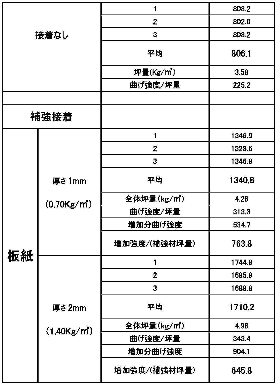
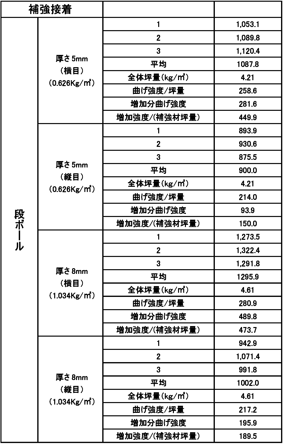
表5と表6との比較から明らかなように、1mm(坪量0.7kg/m2)の板紙を接着したことによる曲げ強度1,340.8kg/mは、5mm(坪量0.626kg/m2)の段ボールを接着した場合の横目の曲げ強度1,087.8kg/m、および縦目の曲げ強度900.0kg/mを顕著に上回った。それどころか、厚さ8mm(坪量1.034kg/m)の段ボールを接着した場合の曲げ強度すら上回ったことは驚くべきことであった。板紙を用いた場合は、段ボールを用いた場合に比べて、厚さを増やすことなく曲げ強度を増加させることができるため、厚み当たりの曲げ強度や、坪量当たりの曲げ強度が顕著に大きい。
In the board structure of this example, 700 g / m 2 (thickness: about 1 mm) roll paper was used as the liner paper layers 1 and 2. The thickness of the board-like structure was 30 mm. Each board was allowed to stand for 24 hours under conditions of a temperature of 23 ° C. and a humidity of 50%. Thereafter, the bending strength (Kg / m) of each structure was measured by converting the measured value at a single point concentrated load (load by force point 30 in FIG. 4) at a speed of 10 mm / min.
As is clear from the comparison between Table 5 and Table 6, the bending strength of 1,340.8 kg / m by bonding a 1 mm (basis weight 0.7 kg / m 2 ) paperboard is 5 mm (basis weight 0.626 kg). / M 2 ), the transverse bending strength of 107.8 kg / m and the longitudinal bending strength of 900.0 kg / m markedly exceeded. On the contrary, it was surprising that the bending strength when the corrugated cardboard having a thickness of 8 mm (basis weight 1.034 kg / m) was bonded was exceeded. When using paperboard, the bending strength can be increased without increasing the thickness as compared with the case where cardboard is used. Therefore, the bending strength per thickness and the bending strength per basis weight are remarkably large.
追加の紙層として段ボールを用いた場合には、横目と縦目とで曲げ強度に大きな相違が生じている点に留意すべきである。この曲げ強度の相違は、ボードをパレット上板として使用する場合には重要になり得る。特に、「四方差し」と呼ばれるX・Y両方向からリフト爪が差し込めるタイプのパレットにおいては、強度の弱い縦目の曲げ強度を基準とせざるを得なくなるからである。これを補うために段ボールを2枚クロス貼りしたものも存在するが、その厚さがさらに大きくなることは避けられない。この点、板紙を接着したボードでは方向による強度差がないため、有利である。
Note that when corrugated cardboard is used as the additional paper layer, there is a large difference in bending strength between the horizontal and vertical eyes. This difference in bending strength can be important when the board is used as a pallet top plate. In particular, in a pallet of a type in which lift claws can be inserted from both the X and Y directions, which is called “four-way insertion”, the bending strength of the weaker longitudinal eye must be used as a reference. In order to compensate for this, there is a cross-bonded two cardboard, but it is inevitable that the thickness is further increased. In this respect, the board to which the paperboard is bonded is advantageous because there is no difference in strength depending on the direction.
さらに、湿度による影響を試験した。「23℃・50%」のボードについては温度23℃、湿度50%条件に24時間、「40℃・90%」のボードについては温度40℃、湿度90%条件に静置した。その後、10mm/分の速度での一点集中荷重(図4の力点30による荷重)での測定値を換算することによって各構造体の曲げ強度(Kg/m)を計測した。
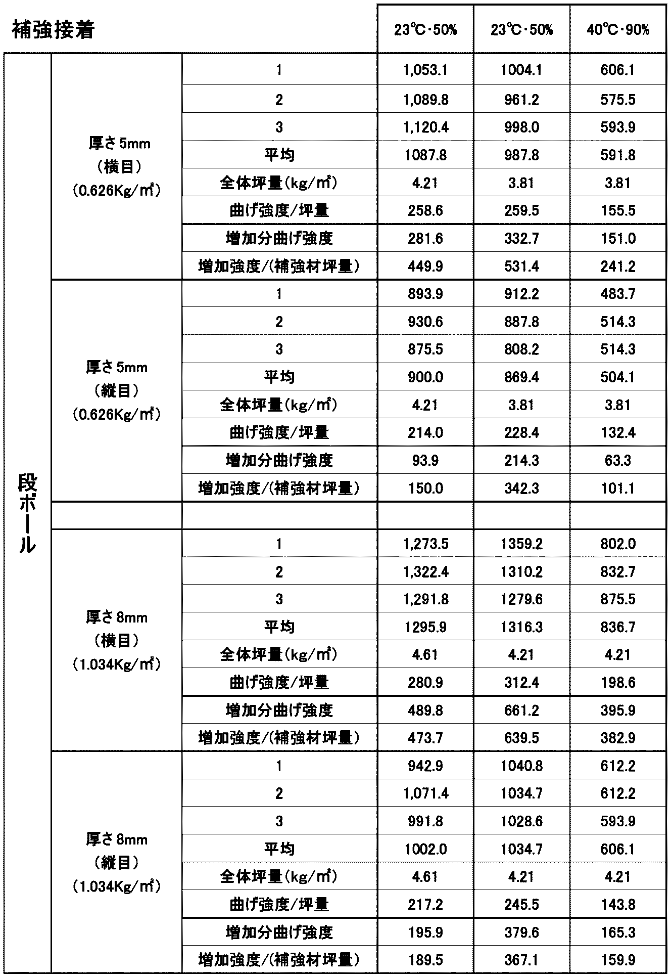
上記表7および表8から明らかなように、追加の紙層として段ボールを接着した場合には湿度の影響によって曲げ強度の低下が顕著に大きい。これは、高温・高湿度条件で長時間の運搬に用いられるパレット用途においては特に致命的となり得る。
In addition, the effect of humidity was tested. The “23 ° C./50%” board was allowed to stand for 24 hours under conditions of a temperature of 23 ° C. and a humidity of 50%, and the “40 ° C./90%” board was allowed to stand under conditions of a temperature of 40 ° C. and a humidity of 90%. Thereafter, the bending strength (Kg / m) of each structure was measured by converting the measured value at a single point concentrated load (load by force point 30 in FIG. 4) at a speed of 10 mm / min.
As is clear from Tables 7 and 8 above, when corrugated cardboard is bonded as an additional paper layer, the bending strength is significantly reduced due to the influence of humidity. This can be particularly fatal in pallet applications that are used for long-time transportation under high temperature and high humidity conditions.
(実施例7)
図7Aおよび7Bに示す切断刃での切断によって製造されたコアにライナ紙層を接着し、さらに追加の板紙層を貼付した場合と、図7Cおよび7Dに示す一般的な切断刃での切断によって製造されたコアにライナ紙層を接着し、さらに追加の板紙層を貼付した場合とを比較した。 (Example 7)
When the liner paper layer is bonded to the core manufactured by cutting with the cutting blade shown in FIGS. 7A and 7B and an additional paperboard layer is pasted, and by cutting with the general cutting blade shown in FIGS. 7C and 7D The liner paper layer was bonded to the manufactured core and compared with the case where an additional paperboard layer was attached.
図7Cおよび7Dに示す一般的な切断刃を用いて製造したボードと比較して、図7Aおよび7Bに示す好ましい切断刃を用いて製造されたボードは、より安定して高い曲げ強度を達成した。すなわち、一般的な切断刃を用いて製造したボードにおいては、接着部が高い曲げ強度に耐えることができないことがあるが、好ましい切断刃を用いて製造したボードにおいてはそのようなことがなかった。
Compared to the board made with the general cutting blade shown in FIGS. 7C and 7D, the board made with the preferred cutting blade shown in FIGS. 7A and 7B achieved a more stable and high bending strength. . That is, in a board manufactured using a general cutting blade, the bonded portion may not be able to withstand high bending strength, but in a board manufactured using a preferable cutting blade, there was no such thing. .
(実施例8)
以下のように実施例8および比較例のパレットを製造した。 (Example 8)
The pallets of Example 8 and Comparative Example were manufactured as follows.
以下のように実施例8および比較例のパレットを製造した。 (Example 8)
The pallets of Example 8 and Comparative Example were manufactured as follows.
株式会社エコボード(日本、岡山)から販売されているエコボード(登録商標)(短手方向800mm×長手方向1150mm×高さ20mm)を、四方差し用パレット上板500として使用した。なお、当該エコボードは図1Aに示す構造を実質的に有する。
Eco board (registered trademark) (short direction 800 mm × longitudinal direction 1150 mm × height 20 mm) sold by Eco Board Co., Ltd. (Okayama, Japan) was used as the pallet upper plate 500 for four-way insertion. Note that the eco board substantially has the structure shown in FIG. 1A.
脚部400として、図1Bにコア4として示す構造物を短手方向86mm×長手方向170mm×高さ90mmに成形したものを9個用意した。この脚部を用意するにあたって、図5A~5Cおよび図8A、8Bに示す切断技術を用いた。接着剤としては、段ボール用接着剤である酢酸ビニル樹脂系エマルジョン形接着剤を用いた。
As the leg 400, nine pieces of the structure shown as the core 4 in FIG. 1B were formed in a short direction 86 mm × longitudinal direction 170 mm × height 90 mm were prepared. In preparing the legs, the cutting techniques shown in FIGS. 5A to 5C and FIGS. 8A and 8B were used. As the adhesive, a vinyl acetate resin emulsion adhesive, which is a corrugated cardboard adhesive, was used.
一般的に流通している1100mm×1350mmの厚紙(厚さ4mm)を短冊状に切断し、86mm×1100mmの3枚の第1の底板200を用意した。また、一般的に流通している1100mm×1350mmの厚紙(厚さ2mm)を短冊状に切断し、170mm×760mmの3枚の第2の底板300を用意した。この6つの底板のために用いた厚紙の面積は、約0.672m2である(なお、切断時の紙のロスは多少発生することもある)。厚紙において余った部分は他のパレットの底板として利用可能である。
1100 mm × 1350 mm thick paper (4 mm thickness) that is generally distributed was cut into strips to prepare three first bottom plates 200 of 86 mm × 1100 mm. Further, 1100 mm × 1350 mm thick paper (thickness 2 mm) which is generally distributed was cut into strips, and three second bottom plates 300 of 170 mm × 760 mm were prepared. The area of the cardboard used for these six bottom plates is about 0.672 m 2 (note that some paper loss may occur during cutting). The remaining part of the cardboard can be used as the bottom plate of another pallet.
上記のように用意した上板500、脚部400、第2の底板300、第1の底板200を、図12A~12Cに示すように接着して、本発明の四方差しパレットを製造した。長手方向の脚部と脚部との間の間隔は290mmとし、短手方向の脚部と脚部との間の間隔は251mmとした(図13Aを参照のこと)。
The top plate 500, the leg 400, the second bottom plate 300, and the first bottom plate 200 prepared as described above were bonded as shown in FIGS. 12A to 12C to produce the four-way pallet of the present invention. The distance between the legs in the longitudinal direction was 290 mm, and the distance between the legs in the short direction was 251 mm (see FIG. 13A).
(比較例)
底板以外は、実施例8と同様に製造した。 (Comparative example)
Except for the bottom plate, it was manufactured in the same manner as in Example 8.
底板以外は、実施例8と同様に製造した。 (Comparative example)
Except for the bottom plate, it was manufactured in the same manner as in Example 8.
比較例においては、一般的に流通している1100mm×1350mmの厚紙(厚さ4mm)を760mm×1100mmに切断して、底板130とした。この760mm×1100mmの底板130において、240mm×280mmの開口部600を4つ打ち抜いて形成した(図13Bを参照のこと)。この4mmの厚紙を打ち抜くためには、木型とロータリーダイカッターもしくは平盤ダイカッターという特殊な設備が必要とされる。さらに4mm以上の厚紙を打ち抜く場合には特に、カッターの刃物の寿命が短く、これらが製造コストを押し上げることになる。この底板のために用いた厚紙の面積は約0.844m2である(打ち抜いた開口部は他に使用することができないため使用したものと考える)。また、このようにパレットを製造すると、1枚の厚紙から1枚の底板しか用意することができないため、実質的には、厚紙全体(1.485m2)を使用したこととなる。
In the comparative example, a 1100 mm × 1350 mm cardboard (4 mm thickness) that is generally distributed was cut into 760 mm × 1100 mm to form a bottom plate 130. The bottom plate 130 of 760 mm × 1100 mm was formed by punching four openings 600 of 240 mm × 280 mm (see FIG. 13B). In order to punch out the 4 mm thick paper, special equipment such as a wooden mold and a rotary die cutter or a flat die cutter is required. Furthermore, especially when punching thick paper of 4 mm or more, the life of the cutter blade is short, which increases the manufacturing cost. The area of the cardboard used for this bottom plate is about 0.844 m 2 (the punched opening is considered to be used because it cannot be used elsewhere). In addition, when the pallet is manufactured in this way, only one bottom plate can be prepared from one cardboard, so that the entire cardboard (1.485 m 2 ) is practically used.
(実施例8と比較例との比較)
上記実施例8の厚紙使用面積(約0.672m2)と比較すると、本発明のパレットが厚紙を効率的に利用して底板を用意していることが分かる。 (Comparison between Example 8 and Comparative Example)
Compared with the cardboard use area (about 0.672 m 2 ) of Example 8 above, it can be seen that the pallet of the present invention efficiently prepares the bottom plate using cardboard.
また、実施例8のパレットは、同じサイズの比較例のパレットと比較して、接地面積が有意に小さい。したがって、パレットへの水分の吸収が、比較例と比べて実施例8のパレットにおいては抑えられ、また防水加工を施す必要のある面積が小さくなる。
Also, the pallet of Example 8 has a significantly smaller ground contact area than the pallet of the comparative example of the same size. Therefore, the absorption of moisture into the pallet is suppressed in the pallet of Example 8 compared to the comparative example, and the area that needs to be waterproofed is reduced.
(実施例9)
第2の底板300を、2mmの厚紙を用いて作製した以外は、実施例8と同様に四方差しパレットを製造した。 Example 9
A four-sided pallet was manufactured in the same manner as in Example 8 except that thesecond bottom plate 300 was manufactured using 2 mm thick paper.
第2の底板300を、2mmの厚紙を用いて作製した以外は、実施例8と同様に四方差しパレットを製造した。 Example 9
A four-sided pallet was manufactured in the same manner as in Example 8 except that the
(曲げ強度試験)
実施例8、実施例9および比較例の各パレットについて、一点集中荷重時の曲げ強度を広島県東部工業技術センターにおいて試験した。 (Bending strength test)
About each pallet of Example 8, Example 9, and the comparative example, the bending strength at the time of one point concentrated load was tested in the Hiroshima Prefecture Eastern Industrial Technology Center.
実施例8、実施例9および比較例の各パレットについて、一点集中荷重時の曲げ強度を広島県東部工業技術センターにおいて試験した。 (Bending strength test)
About each pallet of Example 8, Example 9, and the comparative example, the bending strength at the time of one point concentrated load was tested in the Hiroshima Prefecture Eastern Industrial Technology Center.
その結果、実施例8のパレットと実施例9のパレットと比較例のパレットとでは曲げ強度に有意な差がないことが明らかになった。実施例8では第1の底板200のみが4mmであり、第2の底板300は2mmであったのに対して、実施例8および比較例では底板130全体が4mmであった点に留意すべきである。この結果から、四方差しパレットの曲げ強度の強化のために、その底板として、長手方向と短手方向で厚さの異なる厚紙を選定することによって、無駄をさらに排除することができることが明らかになった。すなわち、一般にパレットの長手方向に大きな曲げ強度が要求されるため、長手方向に延びる第1の底板200の厚さまたは坪量を増やすことによって、パレット全体として十分な曲げ強度を達成することができる。
As a result, it was revealed that there was no significant difference in bending strength between the pallet of Example 8, the pallet of Example 9, and the pallet of Comparative Example. It should be noted that in Example 8, only the first bottom plate 200 was 4 mm and the second bottom plate 300 was 2 mm, whereas in Example 8 and the comparative example, the entire bottom plate 130 was 4 mm. It is. From this result, in order to enhance the bending strength of the four-way pallet, it becomes clear that waste can be further eliminated by selecting cardboard with different thicknesses in the longitudinal direction and the short direction as the bottom plate. It was. That is, since a large bending strength is generally required in the longitudinal direction of the pallet, a sufficient bending strength can be achieved as a whole pallet by increasing the thickness or basis weight of the first bottom plate 200 extending in the longitudinal direction. .
本発明は、安価で高い曲げ強度を有する紙製ボード構造体の提供において有用である。本発明によって提供される紙製ボード構造体は木材ボードに匹敵する強度を安価に達成することができ、例えばパレットや型枠としての使用に適している。そして、本発明の紙製ボード構造体は、その全てがリサイクル可能であるため、木材資源の使用量を削減することによって環境問題に大きく寄与することができる。
The present invention is useful in providing a paper board structure that is inexpensive and has high bending strength. The paper board structure provided by the present invention can achieve strength comparable to that of a wood board at low cost, and is suitable for use as, for example, a pallet or a formwork. And since all the paper board structures of this invention are recyclable, it can contribute greatly to an environmental problem by reducing the usage-amount of wood resources.
1 紙層1
2 紙層2
3 紙層3
4 コア
10 紙製ボード構造体
21 芯材
22 ライナ
23 コアユニット
100 四方差しパレット
200 第1の底板
300 第2の底板
400 脚部
500 上板
600 開口部 1Paper layer 1
2Paper layer 2
3Paper layer 3
4Core 10 Paper board structure 21 Core material 22 Liner 23 Core unit 100 Four-way pallet 200 First bottom plate 300 Second bottom plate 400 Leg 500 Upper plate 600 Opening
2 紙層2
3 紙層3
4 コア
10 紙製ボード構造体
21 芯材
22 ライナ
23 コアユニット
100 四方差しパレット
200 第1の底板
300 第2の底板
400 脚部
500 上板
600 開口部 1
2
3
4
Claims (14)
- ボード状構造体と、該ボード状構造体に接着された板紙層とからなる紙製ボードであって、
該ボード状構造体は、コアと、該コアをサンドイッチ様に挟むように該コアに接着された第1のライナ紙層と第2のライナ紙層とを含み、
該板紙層は該第1のライナ紙層に接着されており、
該ボード状構造体の厚みは約15mm~約40mmであり、
該第1のライナ紙層および該第2のライナ紙層の厚みはそれぞれ独立して約0.5mm~約1.2mmであり、
該板紙層の厚みは約1mm~約4mmである、
紙製ボード。 A paper board comprising a board-like structure and a paperboard layer bonded to the board-like structure,
The board-like structure includes a core, and a first liner paper layer and a second liner paper layer bonded to the core so as to sandwich the core therebetween.
The paperboard layer is bonded to the first liner paper layer;
The board-like structure has a thickness of about 15 mm to about 40 mm,
The thickness of the first liner paper layer and the second liner paper layer are each independently about 0.5 mm to about 1.2 mm;
The thickness of the paperboard layer is from about 1 mm to about 4 mm;
Paper board. - 前記ボード状構造体の厚みは約15mm以上約20mm未満であり、前記紙製ボードの曲げ強度は約450kg/m以上である、請求項1に記載の紙製ボード。 The paper board according to claim 1, wherein the thickness of the board-like structure is about 15 mm or more and less than about 20 mm, and the bending strength of the paper board is about 450 kg / m or more.
- 前記ボード状構造体の厚みは約20mm以上約30mm未満であり、前記紙製ボードの曲げ強度は約650kg/m以上である、請求項1に記載の紙製ボード。 The paper board according to claim 1, wherein the thickness of the board-like structure is about 20 mm or more and less than about 30 mm, and the bending strength of the paper board is about 650 kg / m or more.
- 前記ボード状構造体の厚みは約30mm以上約40mm以下であり、前記紙製ボードの曲げ強度は約950kg/m以上である、請求項1に記載の紙製ボード。 The paper board according to claim 1, wherein the thickness of the board-like structure is about 30 mm or more and about 40 mm or less, and the bending strength of the paper board is about 950 kg / m or more.
- 前記板紙層の厚みは約1mm~約2mmである、請求項1~4のいずれか1項に記載の紙製ボード。 The paper board according to any one of claims 1 to 4, wherein the thickness of the paperboard layer is about 1 mm to about 2 mm.
- 前記板紙層の厚みは、前記ボード状構造体の厚みの約20%以下である、請求項1~5のいずれか1項に記載の紙製ボード。 The paper board according to any one of claims 1 to 5, wherein a thickness of the paperboard layer is about 20% or less of a thickness of the board-like structure.
- 前記板紙層の厚みは、前記ボード状構造体の厚みの約15%以下である、請求項6に記載の紙製ボード。 The paper board according to claim 6, wherein the thickness of the paperboard layer is about 15% or less of the thickness of the board-like structure.
- 前記板紙層の厚みは、前記ボード状構造体の厚みの約10%以下である、請求項7に記載の紙製ボード。 The paper board according to claim 7, wherein the thickness of the paperboard layer is about 10% or less of the thickness of the board-like structure.
- 前記コアは、前記第1のライナ紙層または第2のライナ紙層との接着面においてショルダー部分を有する、請求項1~8のいずれか1項に記載の紙製ボード。 The paper board according to any one of claims 1 to 8, wherein the core has a shoulder portion on an adhesive surface with the first liner paper layer or the second liner paper layer.
- 請求項1~9のいずれか1項に記載の紙製ボードを含む、パレット。 A pallet including the paper board according to any one of claims 1 to 9.
- 前記パレットが、第1の方向と、該第1の方向と直交する第2の方向とを有する紙製の四方差しパレットである、請求項10に記載のパレット。 The pallet according to claim 10, wherein the pallet is a paper four-way pallet having a first direction and a second direction orthogonal to the first direction.
- 請求項11に記載のパレットであって、
前記第1の方向に延びる複数の第1の底板と、
前記第2の方向に延び、該第1の底板に接着された複数の第2の底板と、
該第1の底板と該第2の底板とが交わる部分において、該第2の底板に接着された複数の脚部と、
該複数の脚部に接着された上板と
を備えるパレット。 A pallet according to claim 11,
A plurality of first bottom plates extending in the first direction;
A plurality of second bottom plates extending in the second direction and bonded to the first bottom plate;
A plurality of legs bonded to the second bottom plate at a portion where the first bottom plate and the second bottom plate intersect;
A pallet comprising an upper plate bonded to the plurality of legs. - 請求項1~9のいずれか1項に記載の紙製ボードを含む、型枠。 A form including the paper board according to any one of claims 1 to 9.
- 所定の曲げ強度を有する紙製ボードの製造方法であって、
コアと第1のライナ紙層および第2のライナ紙層とを、該コアを該第1のライナ紙層と該第2のライナ紙層とがサンドイッチ様に挟むように接着して、約15mm~約40mmのボード状構造体を形成する工程と、
該所定の曲げ強度に応じて、約1mm~約4mmの板紙層を選択する工程と、
該第1のライナ紙層の表面に該板紙層を接着する工程と
を包含し、該第1のライナ紙層および該第2のライナ紙層はそれぞれ独立して約0.5mm~約1.2mmである、製造方法。 A method for producing a paper board having a predetermined bending strength,
The core is bonded to the first liner paper layer and the second liner paper layer so that the core is sandwiched between the first liner paper layer and the second liner paper layer, and is about 15 mm. Forming a board-like structure of about 40 mm;
Selecting a paperboard layer of about 1 mm to about 4 mm according to the predetermined bending strength;
Adhering the paperboard layer to the surface of the first liner paper layer, wherein the first liner paper layer and the second liner paper layer are each independently about 0.5 mm to about 1. The manufacturing method which is 2 mm.
Priority Applications (3)
| Application Number | Priority Date | Filing Date | Title |
|---|---|---|---|
| US15/555,341 US10160188B2 (en) | 2015-03-05 | 2016-03-04 | Reinforced paper board and pallet using same |
| CN201680001622.3A CN106794687B (en) | 2015-03-05 | 2016-03-04 | Enhance cardboard and the backing plate using the enhancing cardboard |
| EP16758657.7A EP3266611A4 (en) | 2015-03-05 | 2016-03-04 | Board consisting of reinforced paper, and pallet using same |
Applications Claiming Priority (8)
| Application Number | Priority Date | Filing Date | Title |
|---|---|---|---|
| JP2015043647 | 2015-03-05 | ||
| JP2015-043647 | 2015-03-05 | ||
| JP2015-043646 | 2015-03-05 | ||
| JP2015043646 | 2015-03-05 | ||
| JP2015-151102 | 2015-07-30 | ||
| JP2015151102A JP5976902B1 (en) | 2015-07-30 | 2015-07-30 | Paper pallet |
| JP2015251801A JP5960340B1 (en) | 2015-03-05 | 2015-12-24 | Reinforced paper board |
| JP2015-251801 | 2015-12-24 |
Publications (1)
| Publication Number | Publication Date |
|---|---|
| WO2016139961A1 true WO2016139961A1 (en) | 2016-09-09 |
Family
ID=56849311
Family Applications (1)
| Application Number | Title | Priority Date | Filing Date |
|---|---|---|---|
| PCT/JP2016/001215 WO2016139961A1 (en) | 2015-03-05 | 2016-03-04 | Board consisting of reinforced paper, and pallet using same |
Country Status (4)
| Country | Link |
|---|---|
| US (1) | US10160188B2 (en) |
| EP (1) | EP3266611A4 (en) |
| CN (1) | CN106794687B (en) |
| WO (1) | WO2016139961A1 (en) |
Families Citing this family (2)
| Publication number | Priority date | Publication date | Assignee | Title |
|---|---|---|---|---|
| SE543039C2 (en) | 2018-06-27 | 2020-09-29 | Stora Enso Oyj | A corrugated board and use of a linerboard in the manufacturing of a corrugated board to reduce the washboard effect |
| US20210229883A1 (en) * | 2020-01-29 | 2021-07-29 | Jarod D. Wenrick | Biodegradable additive |
Citations (10)
| Publication number | Priority date | Publication date | Assignee | Title |
|---|---|---|---|---|
| JPS60182132U (en) * | 1984-05-15 | 1985-12-03 | 日本建設株式会社 | Simple wall decorative panel made of paper |
| JPS61172026U (en) * | 1985-04-17 | 1986-10-25 | ||
| JPH01154129U (en) * | 1988-04-19 | 1989-10-24 | ||
| JPH0310832A (en) * | 1989-06-08 | 1991-01-18 | Honshu Paper Co Ltd | Corrugated board for keeping freshness of foodstuff |
| JPH07206051A (en) * | 1994-01-01 | 1995-08-08 | Life Shuppan:Kk | Packaging corrugated board for article or material sensitive to environment, and packaging method therefor |
| JPH07223640A (en) * | 1994-02-08 | 1995-08-22 | 総一郎 ▲吉▼田 | Carrier pallet |
| JPH10337687A (en) * | 1997-06-06 | 1998-12-22 | Kanefusa Corp | Tip saw |
| JPH11342551A (en) * | 1998-04-01 | 1999-12-14 | Daizen Kk | Corrugated fiberboard flat plate, its production and device |
| JP2002370739A (en) * | 2001-06-14 | 2002-12-24 | Yamato Shiki Co Ltd | Corrugated cardboard pallet formed with corrugated cardboard beam |
| JP2009046140A (en) * | 2007-08-20 | 2009-03-05 | Shunwa:Kk | Coupling structure and structure using the same |
Family Cites Families (14)
| Publication number | Priority date | Publication date | Assignee | Title |
|---|---|---|---|---|
| JPS54135095A (en) | 1978-04-10 | 1979-10-19 | Totsupan Danbooru Kk | Method of making corrugated cardboard for box |
| JPS56117655A (en) | 1980-02-21 | 1981-09-16 | Tokan Kogyo Co Ltd | Thick paper for paper glass cover and its manufacture |
| US4714026A (en) * | 1985-04-17 | 1987-12-22 | Honda Giken Kogyo Kabushi Kaisha | Pallet for material handling |
| JPH04244397A (en) | 1991-01-29 | 1992-09-01 | Mitsubishi Heavy Ind Ltd | Structural paper cutting slitter |
| JPH0639390U (en) | 1992-11-02 | 1994-05-24 | 株式会社イソワ | Slitter |
| JPH0717543A (en) | 1993-08-06 | 1995-01-20 | Miyoukou Kikai Kogyo Kk | Reinforced type corrugated cardboard pallet |
| JP3013911U (en) | 1995-01-23 | 1995-07-25 | 株式会社エムパックス | Paper pallet |
| JP3516758B2 (en) | 1995-01-27 | 2004-04-05 | 興陽製紙株式会社 | White paperboard for food containers |
| JP2000326435A (en) | 1999-05-25 | 2000-11-28 | Daizen Kk | Corrugated cardboard flat panel |
| JP2001253000A (en) | 2000-03-08 | 2001-09-18 | Daiwa Itagami Kk | Corrugated board and box |
| JP2004131126A (en) | 2002-10-10 | 2004-04-30 | Ric Co Ltd | Paper pallet with reinforcing frame |
| JP4445781B2 (en) | 2004-03-03 | 2010-04-07 | 株式会社エコボード | Hollow formwork for long concrete |
| JP2010106497A (en) | 2008-10-29 | 2010-05-13 | Mitsutaka Onoda | Panel |
| US20120052238A1 (en) | 2010-09-01 | 2012-03-01 | Pregis Innovative Packaging, Inc. | Fire-resistant print board |
-
2016
- 2016-03-04 EP EP16758657.7A patent/EP3266611A4/en not_active Withdrawn
- 2016-03-04 WO PCT/JP2016/001215 patent/WO2016139961A1/en active Application Filing
- 2016-03-04 CN CN201680001622.3A patent/CN106794687B/en not_active Expired - Fee Related
- 2016-03-04 US US15/555,341 patent/US10160188B2/en not_active Expired - Fee Related
Patent Citations (10)
| Publication number | Priority date | Publication date | Assignee | Title |
|---|---|---|---|---|
| JPS60182132U (en) * | 1984-05-15 | 1985-12-03 | 日本建設株式会社 | Simple wall decorative panel made of paper |
| JPS61172026U (en) * | 1985-04-17 | 1986-10-25 | ||
| JPH01154129U (en) * | 1988-04-19 | 1989-10-24 | ||
| JPH0310832A (en) * | 1989-06-08 | 1991-01-18 | Honshu Paper Co Ltd | Corrugated board for keeping freshness of foodstuff |
| JPH07206051A (en) * | 1994-01-01 | 1995-08-08 | Life Shuppan:Kk | Packaging corrugated board for article or material sensitive to environment, and packaging method therefor |
| JPH07223640A (en) * | 1994-02-08 | 1995-08-22 | 総一郎 ▲吉▼田 | Carrier pallet |
| JPH10337687A (en) * | 1997-06-06 | 1998-12-22 | Kanefusa Corp | Tip saw |
| JPH11342551A (en) * | 1998-04-01 | 1999-12-14 | Daizen Kk | Corrugated fiberboard flat plate, its production and device |
| JP2002370739A (en) * | 2001-06-14 | 2002-12-24 | Yamato Shiki Co Ltd | Corrugated cardboard pallet formed with corrugated cardboard beam |
| JP2009046140A (en) * | 2007-08-20 | 2009-03-05 | Shunwa:Kk | Coupling structure and structure using the same |
Non-Patent Citations (1)
| Title |
|---|
| See also references of EP3266611A4 * |
Also Published As
| Publication number | Publication date |
|---|---|
| EP3266611A1 (en) | 2018-01-10 |
| US10160188B2 (en) | 2018-12-25 |
| CN106794687B (en) | 2018-11-09 |
| US20180037015A1 (en) | 2018-02-08 |
| EP3266611A4 (en) | 2018-08-15 |
| CN106794687A (en) | 2017-05-31 |
Similar Documents
| Publication | Publication Date | Title |
|---|---|---|
| US9663267B2 (en) | Shipping pallet apparatus and method | |
| US20100062233A1 (en) | Methods for converting used paper material into structural panels, and structural panels made thereby | |
| JP6088697B2 (en) | Reinforced paper board | |
| RU2376224C2 (en) | Cardboard tray | |
| WO2016139961A1 (en) | Board consisting of reinforced paper, and pallet using same | |
| US20140050897A1 (en) | Packaging structure | |
| CN104742486A (en) | Manufacturing process | |
| JP5976902B1 (en) | Paper pallet | |
| DK201870464A1 (en) | A packaging element for use in packaging of an unmounted product for use at a roof, and a method of use of same | |
| JP5715317B2 (en) | Curing board | |
| US20160039567A1 (en) | Shipping pallet apparatus and method | |
| JP2017030863A (en) | Paper pallet | |
| CN112218756B (en) | Apparatus and method for manufacturing corrugated trays | |
| JP3072104U (en) | Cardboard pallets | |
| WO2008026259A1 (en) | Corrugated board pallet manufacturing method, and pallet | |
| CN202557944U (en) | Novel grass core paper pallet | |
| KR100469541B1 (en) | The pallet which using the carry goods | |
| JPS5855183Y2 (en) | shock absorber | |
| CN203143189U (en) | Heavy-duty pallet | |
| TWM397357U (en) | Environmentally-friendly heavy-duty card board structure | |
| PL221276B1 (en) | Furniture board and a method for producing furniture boards | |
| JP2002087435A (en) | Binding machine for paper-base laminate | |
| JPH08169447A (en) | Pallet and constituting member thereof | |
| JP2004256111A (en) | Loading pallet beam material and loading pallet | |
| JPH0686927U (en) | Frame material for flash panel |
Legal Events
| Date | Code | Title | Description |
|---|---|---|---|
| 121 | Ep: the epo has been informed by wipo that ep was designated in this application |
Ref document number: 16758657 Country of ref document: EP Kind code of ref document: A1 |
|
| REEP | Request for entry into the european phase |
Ref document number: 2016758657 Country of ref document: EP |
|
| WWE | Wipo information: entry into national phase |
Ref document number: 15555341 Country of ref document: US |
|
| NENP | Non-entry into the national phase |
Ref country code: DE |