WO2016139770A1 - 画像処理装置 - Google Patents
画像処理装置 Download PDFInfo
- Publication number
- WO2016139770A1 WO2016139770A1 PCT/JP2015/056322 JP2015056322W WO2016139770A1 WO 2016139770 A1 WO2016139770 A1 WO 2016139770A1 JP 2015056322 W JP2015056322 W JP 2015056322W WO 2016139770 A1 WO2016139770 A1 WO 2016139770A1
- Authority
- WO
- WIPO (PCT)
- Prior art keywords
- vertex
- area
- pixel
- region
- label
- Prior art date
- Legal status (The legal status is an assumption and is not a legal conclusion. Google has not performed a legal analysis and makes no representation as to the accuracy of the status listed.)
- Ceased
Links
Images




















Classifications
-
- G—PHYSICS
- G06—COMPUTING OR CALCULATING; COUNTING
- G06T—IMAGE DATA PROCESSING OR GENERATION, IN GENERAL
- G06T5/00—Image enhancement or restoration
- G06T5/70—Denoising; Smoothing
-
- G—PHYSICS
- G06—COMPUTING OR CALCULATING; COUNTING
- G06F—ELECTRIC DIGITAL DATA PROCESSING
- G06F9/00—Arrangements for program control, e.g. control units
- G06F9/06—Arrangements for program control, e.g. control units using stored programs, i.e. using an internal store of processing equipment to receive or retain programs
- G06F9/46—Multiprogramming arrangements
- G06F9/50—Allocation of resources, e.g. of the central processing unit [CPU]
-
- G—PHYSICS
- G06—COMPUTING OR CALCULATING; COUNTING
- G06F—ELECTRIC DIGITAL DATA PROCESSING
- G06F9/00—Arrangements for program control, e.g. control units
- G06F9/06—Arrangements for program control, e.g. control units using stored programs, i.e. using an internal store of processing equipment to receive or retain programs
- G06F9/46—Multiprogramming arrangements
- G06F9/50—Allocation of resources, e.g. of the central processing unit [CPU]
- G06F9/5061—Partitioning or combining of resources
- G06F9/5066—Algorithms for mapping a plurality of inter-dependent sub-tasks onto a plurality of physical CPUs
-
- G—PHYSICS
- G06—COMPUTING OR CALCULATING; COUNTING
- G06T—IMAGE DATA PROCESSING OR GENERATION, IN GENERAL
- G06T5/00—Image enhancement or restoration
- G06T5/73—Deblurring; Sharpening
-
- G—PHYSICS
- G06—COMPUTING OR CALCULATING; COUNTING
- G06T—IMAGE DATA PROCESSING OR GENERATION, IN GENERAL
- G06T7/00—Image analysis
- G06T7/10—Segmentation; Edge detection
- G06T7/11—Region-based segmentation
-
- G—PHYSICS
- G06—COMPUTING OR CALCULATING; COUNTING
- G06T—IMAGE DATA PROCESSING OR GENERATION, IN GENERAL
- G06T7/00—Image analysis
- G06T7/10—Segmentation; Edge detection
- G06T7/13—Edge detection
-
- G—PHYSICS
- G06—COMPUTING OR CALCULATING; COUNTING
- G06T—IMAGE DATA PROCESSING OR GENERATION, IN GENERAL
- G06T7/00—Image analysis
- G06T7/10—Segmentation; Edge detection
- G06T7/187—Segmentation; Edge detection involving region growing; involving region merging; involving connected component labelling
-
- G—PHYSICS
- G06—COMPUTING OR CALCULATING; COUNTING
- G06T—IMAGE DATA PROCESSING OR GENERATION, IN GENERAL
- G06T7/00—Image analysis
- G06T7/60—Analysis of geometric attributes
-
- G—PHYSICS
- G06—COMPUTING OR CALCULATING; COUNTING
- G06T—IMAGE DATA PROCESSING OR GENERATION, IN GENERAL
- G06T2207/00—Indexing scheme for image analysis or image enhancement
- G06T2207/20—Special algorithmic details
- G06T2207/20112—Image segmentation details
- G06T2207/20156—Automatic seed setting
-
- G—PHYSICS
- G06—COMPUTING OR CALCULATING; COUNTING
- G06T—IMAGE DATA PROCESSING OR GENERATION, IN GENERAL
- G06T2207/00—Indexing scheme for image analysis or image enhancement
- G06T2207/20—Special algorithmic details
- G06T2207/20172—Image enhancement details
- G06T2207/20192—Edge enhancement; Edge preservation
Definitions
- the present invention relates to an image processing apparatus.
- Patent Document 1 among the voxels constituting the volume data, by dividing the number of surface voxels located on the surface visible from the projection surface side when the display object is projected, it is divided substantially equally, A technique of a three-dimensional image generation apparatus that operates each computing resource without being idle is disclosed.
- area division processing that divides image data into a plurality of areas based on data such as luminance values.
- This region division processing is applied in various fields such as cell analysis.
- the technique disclosed in Patent Document 1 is a technique of a method of drawing (displaying) an image of a human body measured by an X-ray CT (Computed Tomography) apparatus or the like by processing with volume rendering.
- a threshold is set for tissue opacity or the like in a human body, and a tissue whose opacity value is equal to or greater than the threshold is determined as a display target. It is noted that the range to be determined is determined and the amount of calculation when generating a three-dimensional image can be estimated.
- the technique disclosed in Patent Document 1 is a technique related to a method for estimating a calculation amount specific to volume rendering processing. Note that Patent Document 1 does not disclose a specific method for assigning processing to each computation resource based on the estimated calculation amount so that the computation load is substantially equal.
- Patent Document 1 it is difficult to apply the technique disclosed in Patent Document 1 as it is to the estimation of the computation load in the region division processing. That is, for example, in the region division processing for a gray scale image or the like, it is not possible to estimate the calculation load by the technique disclosed in Patent Document 1.
- the present invention has been made on the basis of the above problems, and when performing computation in parallel with a plurality of computation resources for the purpose of shortening the processing time in the area division processing, each computation resource is not idled.
- An object of the present invention is to provide an image processing apparatus that can be operated to reduce the overall processing time.
- the image processing apparatus sequentially pays attention to each pixel included in the input image, and the luminance value of the focused pixel and the other pixels located around the focused pixel A first label indicating a direction toward the pixel having a higher luminance value, or a second label indicating a higher luminance value than all of the surrounding pixels.
- the gradient data generation unit for generating gradient data representing each of the pixels included in the image, and each of the pixels represented by the second label is a vertex pixel, and represents the position of the vertex pixel Based on the vertex coordinates, the region in the image is divided into regions including the pixels belonging to the same vertex pixel, and the pixels included in the divided regions are the pixels belonging to the same vertex pixel.
- a plurality of region label generation units that generate region label data represented by a third label having a value indicating the presence of the pixel, and each of the region label generation units includes a region in the image belonging to the same vertex pixel;
- a vertex pixel distribution unit that distributes each of the vertex pixels to be subjected to the calculation to each of the region label generation units so that the load of the calculation to be divided into the regions including is equalized.
- the vertex pixel distribution unit has a predetermined range from the vertex pixel at the center when the vertex pixel is at the center.
- a region area estimation that estimates, for each of the vertex pixels, a region area representing the size of the region of the pixel belonging to the vertex pixel as a center based on the number of other vertex pixels located in the region
- Each vertex pixel is assigned to each of the region label generation units so that a difference in the region area corresponding to the vertex pixel to be calculated is minimized based on the area and each of the region areas
- a vertex coordinate distribution scheduling unit for assigning a distribution signal representing the allocated area label generation unit to the vertex coordinates corresponding to each of the vertex pixels, and each of the vertex coordinates On the basis of the distribution signal that is applied to, and the vertex coordinate distribution unit which outputs the vertex coordinates in the region label generating unit in which the distribution signals represented may be provided.
- the region area estimation unit includes the vertex coordinates of the vertex pixel as a center and the vertex coordinates of the other vertex pixels. Based on the above, the distance between the two vertex pixels is calculated respectively, and based on the calculated distance between the two vertex pixels, within a predetermined distance range from the position of the vertex pixel as the center The number of other vertex pixels existing in the region may be counted, and the area of the region corresponding to each vertex pixel may be estimated using the inverse of the counted number of other vertex pixels.
- the region area estimation unit applies a region within a predetermined range from the vertex pixel as a center. Based on the number of the other vertex pixels located and the number of the vertex pixels represented by a plurality of predetermined area area thresholds, the area area corresponding to each of the vertex pixels is determined in advance. Alternatively, it may be estimated to any one of the threshold values of the plurality of region areas.
- the vertex coordinate distribution scheduling unit assigns the vertex pixels in a predetermined order based on the corresponding area area.
- a sorting unit that rearranges the vertex pixels after the sorting unit has rearranged them, may be assigned to each of the region label generation units.
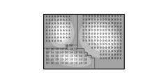
- FIG. 1A illustrates an example of a luminance image that is a target of region division processing in the image processing apparatus 1.
- the luminance image shown in FIG. 1A is a grayscale image having three pixels with the highest luminance value (hereinafter referred to as “vertex pixels”) among the surrounding pixels.
- the gradient data is data representing each pixel with a value that is a gradient label.
- the gradient is schematically represented by an arrow on the luminance image shown in FIG. 1A.
- the gradient data is shown in the form of overlapping the gradient labels shown in FIG.
- the pixel located in the position shown as "8", “9", “10” in FIG. 1B is a vertex pixel.
- vertex label the value indicating the vertex (hereinafter referred to as “vertex label”) is represented in the gradient data in the vertex pixel.
- each of “8”, “9”, and “10” is a vertex label.
- the image processing apparatus 1 performs region division processing for dividing the region in the luminance image into regions including pixels belonging to the same vertex pixel based on the gradient label and the vertex label included in the gradient data.
- this area division processing the image processing apparatus 1 performs an operation for assigning a value indicating a pixel belonging to the same area (hereinafter referred to as “area label”) to each peripheral pixel belonging to the same vertex pixel.
- Area label a value indicating a pixel belonging to the same area
- FIG. 1C shows an example of region label data that is a result of the calculation performed by the image processing apparatus 1 to assign region labels. As shown in FIG.
- the region label data is data in which the peripheral pixels belonging to the same vertex pixel are each given the same value as the vertex label assigned to the vertex pixel as the region label.
- the region label data is shown in a form in which the region label is superimposed on the luminance image shown in FIG. 1A.
- the region division processing for assigning the same region label to the peripheral pixels belonging to the same vertex pixel is performed in parallel with a plurality of computation resources.
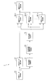
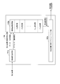
- FIG. 2 is a block diagram showing an example of a schematic configuration of the image processing apparatus 1 according to the first embodiment of the present invention.
- the image processing apparatus 1 shown in FIG. 2 includes a gradient data generation unit 11, a gradient data storage unit 12, a vertex coordinate storage unit 13, a vertex coordinate distribution signal generation unit 14, a vertex coordinate distribution unit 15, and n pieces.
- Region label generation units 16-1 to 16-n and a region label storage unit 17 are provided.
- the gradient data generation unit 11 generates gradient data corresponding to the input luminance image, and outputs the generated gradient data to the gradient data storage unit 12. More specifically, the gradient data generation unit 11 determines whether each pixel included in the luminance image is a vertex pixel or a peripheral pixel, and assigns a vertex label to the vertex pixel and a gradient label to the peripheral pixel. Each assigned gradient data is generated. Then, the gradient data generation unit 11 outputs the generated gradient data to the gradient data storage unit 12. Further, the gradient data generation unit 11 outputs coordinates (hereinafter referred to as “vertex coordinates”) representing the position of the vertex pixel included in the generated gradient data to the vertex coordinate storage unit 13.
- vertex coordinates coordinates
- the vertex coordinate distribution unit 15 distributes (distributes) each input vertex coordinate to the corresponding computation resource based on the distribution signal given to the vertex coordinate input from the vertex coordinate distribution signal generation unit 14.
- Each of the region label generation unit 16-1 to the region label generation unit 16-n is a calculation resource included in the image processing apparatus 1 that performs a calculation for assigning a region label to peripheral pixels belonging to the same vertex pixel in the luminance image.
- Each of the area label generation unit 16-1 to the area label generation unit 16-n includes a vertex assigned to the vertex pixel to each of the peripheral pixels belonging to the vertex pixel located at the vertex coordinate input from the vertex coordinate distribution unit 15. Assign a region label with the same value as the label.
- each of the region label generation unit 16-1 to the region label generation unit 16-n calculates a region of peripheral pixels belonging to the same vertex pixel based on the gradient data stored in the gradient data storage unit 12.
- the region label storage unit 17 stores the region labels output from each of the region label generation unit 16-1 to the region label generation unit 16-n.
- the area label storage unit 17 stores area label data as shown in FIG. 1C.
- the image processing apparatus 1 performs region division processing for generating region label data in which the same region label as the vertex label is assigned to the peripheral pixels belonging to the same vertex pixel in parallel using a plurality of computation resources.
- the gradient data generation unit 11 determines whether the pixel is a vertex pixel or a peripheral pixel in raster order from the pixel arranged at the upper left of the input luminance image.
- the current pixel for which it is determined whether it is a vertex pixel or a peripheral pixel is referred to as a “target pixel”.
- the gradient data generation unit 11 assigns a vertex label or a gradient label to each target pixel according to the result of determining whether the target pixel is a vertex pixel or a peripheral pixel.
- the values of the vertex label and the gradient label that the gradient data generation unit 11 assigns to each pixel of interest are the luminance value of the pixel of interest and the pixels located around the pixel of interest (hereinafter referred to as “surrounding pixels”). It is predetermined based on the relationship with the luminance value.
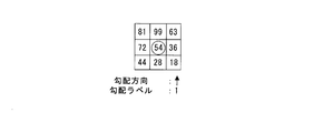
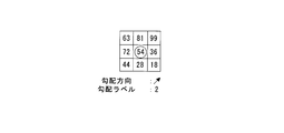
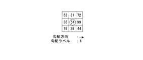
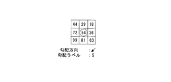
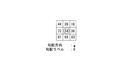
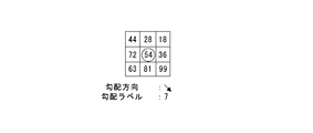
- the gradient data generation unit 11 assigns gradient labels having values (“1” to “7”) corresponding to the direction in which surrounding pixels having a high luminance value are located, as viewed from the target pixel, to each target pixel.
- FIG. 3B shows an example in which the gradient data generation unit 11 determines that the vertex pixel to which the target pixel belongs is located in the upward direction, and gives a gradient label having a value “1” to the target pixel.
- 3C shows an example in which the gradient data generation unit 11 determines that the vertex pixel to which the target pixel belongs is located in the diagonally upper right direction, and gives a gradient label having a value “2” to the target pixel. Show. FIG.
- FIG. 3G shows an example in which the gradient data generation unit 11 determines that the vertex pixel to which the target pixel belongs is located in the downward direction, and adds a gradient label having a value of “6” to the target pixel. Yes.
- FIG. 3H shows an example in which the gradient data generation unit 11 determines that the vertex pixel to which the target pixel belongs is located in the diagonally lower right direction, and gives a gradient label having a value of “7” to the target pixel. Show.
- the gradient data generation unit 11 determines whether or not the luminance value of the current pixel of interest is higher than the luminance values of any surrounding pixels (step S14). That is, in step S14, the gradient data generation unit 11 determines whether or not the current target pixel is a vertex pixel.
- step S14 when it is determined in step S14 that the luminance value of the current pixel of interest is higher than the luminance values of any surrounding pixels, that is, the current pixel of interest is a vertex pixel (“YES” in step S14). ”),
- the gradient data generation unit 11 outputs the current position of the pixel of interest, that is, the vertex coordinates indicating the position of the vertex pixel, to the vertex coordinate storage unit 13.
- the gradient data generation unit 11 performs the target pixel determination process represented by the loop in step S12 on all the pixels included in the luminance image, that is, performs one frame of the luminance image. Then, gradient data corresponding to the input luminance image is generated. Thereby, the gradient data storage unit 12 stores gradient data in which gradient labels or vertex labels are assigned to the respective pixels.
- the vertex coordinate storage unit 13 stores vertex coordinates representing the positions of the respective vertex pixels included in the gradient data stored in the gradient data storage unit 12.
- the vertex coordinate distribution signal generation unit 14 performs a process of assigning an area label generation unit 16 that performs an operation on the vertex pixels corresponding to each vertex coordinate based on the vertex coordinates stored in the vertex coordinate storage unit 13.
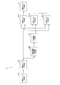
- FIG. 5 is a block diagram illustrating a configuration of the vertex coordinate distribution signal generation unit 14 included in the image processing apparatus 1 according to the first embodiment of the present invention.
- the vertex coordinate distribution signal generation unit 14 illustrated in FIG. 5 includes a region area estimation unit 141, a region area storage unit 142, and a vertex coordinate distribution scheduling unit 143.
- the area area storage unit 142 stores the area area information output from the area area estimation unit 141.
- the vertex coordinate distribution scheduling unit 143 assigns the operation for each vertex pixel to each of the region label generation units 16 based on the area area information stored in the region area storage unit 142. Then, the vertex coordinate distribution scheduling unit 143 gives a distribution signal representing the region label generation unit 16 to which the operation is assigned to each vertex coordinate.
- each component provided in the vertex coordinate distribution signal generation unit 14 will be described.
- the area area estimation unit 141 will be described.
- the image processing apparatus 1 when pixels included in the input luminance image are determined in the raster order, and the area area is calculated in the order determined as the vertex pixels, each vertex pixel in the luminance image is calculated.
- a large difference occurs in the calculation load of each area label generation unit 16. That is, a difference occurs in the size of the area where each area label generation unit 16 performs the calculation, and the calculation load is not uniform. Therefore, in the image processing apparatus 1, first, the area area estimation unit 141 simply estimates the area area belonging to each vertex pixel based on the vertex coordinates stored in the vertex coordinate storage unit 13.
- the vertex coordinate distribution scheduling unit 143 is based on the estimated region area so that the difference in the size of the region areas to be calculated by the respective region label generation units 16 is minimized.
- the calculation for each vertex pixel can be distributed. That is, in the image processing apparatus 1, the area label generation unit 16 that calculates the respective vertex pixels so that the calculation load when the area area is finally calculated is substantially equal based on the estimated area area. Can be sorted.
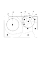
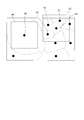
- FIG. 6 is a diagram for explaining the concept of region area estimation processing performed in the region area estimation unit 141 included in the image processing apparatus 1 according to the first embodiment of the present invention.
- the positions of the respective vertex pixels included in the luminance image are indicated by black circles, and the final result when each of the area label generation units 16 included in the image processing apparatus 1 performs the area dividing process.
- the boundary of the area is schematically shown by a dotted line.
- vertex density the density of existing vertex pixels
- a region (hereinafter referred to as “threshold region”) set by a predetermined distance threshold is indicated by a one-dot chain line.
- threshold region a1 there are three other vertex pixels (vertex pixel t1, vertex pixel t2, and vertex pixel t4) in the threshold region a1 centered on the vertex pixel t3, and the threshold region centered on the vertex pixel t5. This shows a case where no other vertex pixel exists in a2. This indicates that the vertex density of the threshold region a1 is four times higher than the vertex density of the threshold region a2.
- the vertex density that is, the number of vertex pixels existing in the unit area indicated by the threshold region is large when the region area belonging to the vertex pixel existing in the threshold region is small, and the region area is wide. If you get smaller. From this, the area area estimation unit 141 simply estimates the area area belonging to each vertex pixel using the reciprocal of the vertex density. For example, in the example illustrated in FIG. 6, it is estimated that the area area belonging to each vertex pixel in the threshold area a ⁇ b> 1 is equal to or less than 1 ⁇ 4 of the threshold area, and the area area belonging to the vertex pixel in the threshold area a ⁇ b> 2. Is estimated to be greater than or equal to the area of the threshold region.
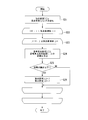
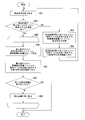
- FIG. 7 is a flowchart showing a processing procedure in the area area estimation unit 141 provided in the image processing apparatus 1 according to the first embodiment of the present invention.
- the area area estimation unit 141 determines whether or not the vertex pixel exists in the threshold region based on the distance between the two vertex pixels obtained from the respective vertex coordinates. Judgment is made. More specifically, the area area estimation unit 141 determines the other vertex pixels based on the distance between the two vertex pixels between the reference vertex pixel located at the center of the threshold region for calculating the vertex density and the other vertex pixels. It is determined whether or not the vertex pixel is within the threshold region of the reference vertex pixel. At this time, the area area estimation unit 141 does not perform the distance calculation for the two vertex pixels for which the distance calculation has already been completed.
- the area area estimation unit 141 first corresponds to the loop counter i and represents a vertex coordinate “0” (hereinafter referred to as “reference vertex coordinate [0]”) that represents the position of the reference vertex pixel that is the center of the threshold region first. ) And the vertex coordinate “1” (hereinafter referred to as “distance calculation vertex coordinate [1]”) representing the position of the other vertex pixel for calculating the distance from the reference vertex pixel corresponding to the loop counter j. Is acquired from the vertex coordinate storage unit 13.
- the area area estimation unit 141 calculates the distance between the two vertex pixels from the reference vertex coordinate [0] and the distance calculation vertex coordinate [1] acquired from the vertex coordinate storage unit 13 (step S24). Note that the calculation of the distance between the two vertex pixels in step S24 is performed by a known distance calculation method such as a Euclidean distance or an urban area distance.
- the area area estimation unit 141 uses the vertex coordinates representing the position of the first vertex pixel t3 as the reference vertex coordinates [0], and uses the vertex coordinates representing the position of the second vertex pixel t4 as the distance calculation vertex coordinates [ 1] is obtained from the vertex coordinate storage unit 13, and the distance between the first vertex pixel t3 and the second vertex pixel t4 is calculated.
- the area area estimation unit 141 calculates whether or not the calculated distance between the vertex pixels is equal to or smaller than a predetermined distance threshold, that is, within a threshold area centered on the reference vertex coordinate [0]. It is determined whether or not the vertex coordinate [1] exists (step S25).
- the area area estimation unit 141 corresponds to the second vertex pixel t4 in the threshold area a1 centered on the reference vertex coordinate [0] corresponding to the first vertex pixel t3. It is determined whether or not the distance calculation vertex coordinate [1] to be present exists.
- step S25 If it is determined in step S25 that the distance between the vertex pixels is equal to or smaller than the threshold value, that is, the distance calculation vertex coordinate [1] exists in the threshold region centered on the reference vertex coordinate [0] (“YES” in step S25) ”), The area area estimation unit 141 adds“ 1 ”to the vertex density [0] corresponding to the reference vertex pixel. Further, the area area estimation unit 141 adds “1” to the vertex density [1] corresponding to the other vertex pixel whose distance from the reference vertex pixel is calculated (step S26).
- the area area estimation unit 141 adds “1” to the value of the vertex density [0] corresponding to the first vertex pixel t3, and corresponds to the second vertex pixel t4.
- the vertex pixel t3 and the vertex pixel t4 exist in each other's threshold region.
- the area area estimation unit 141 acquires the distance calculation vertex coordinate [2] corresponding to the loop counter j from the vertex coordinate storage unit 13 in step S24, and the reference vertex coordinate [0 ] And the distance calculation vertex coordinates [2], the distance between the two vertex pixels is calculated.
- the area area estimation unit 141 sets the vertex coordinate indicating the position of the third vertex pixel t5 as the distance calculation vertex coordinate [2], and the vertex coordinate storage unit 13 And the distance between the first vertex pixel t3 and the third vertex pixel t5 is calculated.
- step S25 the area area estimation unit 141 determines whether or not the calculated distance between the vertex pixels is equal to or smaller than a predetermined distance threshold, that is, a threshold area centered on the reference vertex coordinate [0]. It is determined whether or not the distance calculation vertex coordinates [2] are present.
- a predetermined distance threshold that is, a threshold area centered on the reference vertex coordinate [0]. It is determined whether or not the distance calculation vertex coordinates [2] are present.
- the area area estimation unit 141 includes 3 in the threshold area a1 centered on the reference vertex coordinate [0] corresponding to the first vertex pixel t3. It is determined whether or not a distance calculation vertex coordinate [2] corresponding to the first vertex pixel t5 exists.
- step S25 If it is determined in step S25 that the distance between the vertex coordinates is not less than or equal to the threshold value, that is, the distance calculation vertex coordinate [2] does not exist within the threshold region centered on the reference vertex coordinate [0] (“NO” in step S25) ")
- the distance between the second vertex pixel t4 and the first vertex pixel t3 is not calculated in the first loop of step S23. This is because the calculation of the distance between the first vertex pixel t3 and the second vertex pixel t4 has already been completed in the processing of the first loop in step S22. This is to avoid redundant calculation of the distance.
- step S25 the area area estimation unit 141 determines whether or not the calculated distance between the vertex pixels is equal to or less than a predetermined distance threshold, that is, a threshold area centered on the reference vertex coordinate [1]. It is determined whether or not the distance calculation vertex coordinates [2] are present.
- a predetermined distance threshold that is, a threshold area centered on the reference vertex coordinate [1]. It is determined whether or not the distance calculation vertex coordinates [2] are present.
- the vertex coordinate distribution scheduling unit 143 reads out the vertex coordinates associated with the area area information (reciprocal of the vertex density) stored in the area area storage unit 142, and the area area where each area label generation unit 16 performs the calculation
- the vertex coordinate distribution unit 15 is provided with a distribution signal to the read vertex coordinates so that the difference between the sums is minimized, that is, so that the sum of the calculation loads performed by the region label generation units 16 is substantially equal. Output to.
- FIG. 8 is a block diagram illustrating a configuration of the vertex coordinate distribution scheduling unit 143 provided in the image processing apparatus 1 according to the first embodiment of the present invention.
- the vertex coordinate distribution scheduling unit 143 illustrated in FIG. 8 includes a sorting unit 1431, a sorted vertex coordinate storage unit 1432, and a distribution signal providing unit 1433.
- the distribution signal giving unit 1433 sequentially reads out the respective vertex coordinates stored in the sorted vertex coordinate storage unit 1432 in the order stored in the sorted vertex coordinate storage unit 1432, and assigns operations to the read vertex coordinates.
- a distribution signal representing the region label generation unit 16 is given and output to the vertex coordinate distribution unit 15.
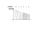
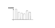
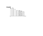
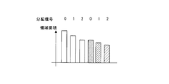
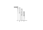
- FIG. 9A to FIG. 9D are diagrams for explaining the concept of distribution signal assignment processing by the vertex coordinate distribution scheduling unit 143 provided in the image processing apparatus 1 according to the first embodiment of the present invention.
- the horizontal axis represents the arrangement of the vertex coordinates
- the vertical axis represents the size of the area estimated at each vertex coordinate.
- the horizontal axis represents each region label generation unit 16
- the vertical axis represents the calculation load assigned to each region label generation unit 16 in terms of the size of the region.
- FIG. 9D shows the calculation load of the region label generation unit 16-0 to the region label generation unit 16-2 when the respective vertex coordinates are assigned as in the example shown in FIG. 9C in terms of the size of the region area. Represents.
- FIG. 9D by assigning the calculation load to each area label generation unit 16 in combination with the vertex coordinates having the largest area area and the vertex coordinates having the smallest area area, as in the example shown in FIG. 9C. As described above, the sum of the calculation loads of the respective area label generation units 16 becomes substantially equal.
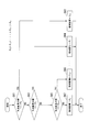
- the distribution signal giving unit 1433 clears the vertex pixel loop counter i from which the vertex coordinates are read to “0” in the loop of step S32.
- step S36 the distribution signal applying unit 1433 returns to Step S32 and performs a distribution signal applying process for the next vertex coordinate.
- step S34 determines “1” from the value of the current distribution signal. Is subtracted to decrement the value of the distribution signal (step S37).
- the distribution signal providing unit 1433 adds “1” to the value of the decremented distribution signal, and sets the value of the distribution signal to “0”. Fix (clip) (step S38). If the value of the decremented distribution signal is not “0” or less, the process of step S38 is not performed. Then, the distribution signal applying unit 1433 returns to Step S32 and performs a distribution signal applying process for the next vertex coordinate.
- the distribution signal applying unit 1433 performs the distribution signal applying process represented by the loop in step S32 on all the vertex coordinates stored in the sorted vertex coordinate storage unit 1432, and distributes the distribution signal to each vertex coordinate. Is granted.
- the vertex coordinate distribution signal generation unit 14 is a region in which computations for assigning region labels to peripheral pixels belonging to the same vertex pixel in the luminance image are computation resources provided in the image processing apparatus 1.
- the vertex coordinates to which the distribution signal for distributing the labels so as to be substantially equalized by the label generation unit 16 is output to the vertex coordinate distribution unit 15.
- the vertex coordinate distribution unit 15 distributes each vertex coordinate to the corresponding region label generation unit 16 based on the distribution signal given to the vertex coordinates input from the vertex coordinate distribution signal generation unit 14 ( Distribute).
- Distribute distribution signal given to the vertex coordinates input from the vertex coordinate distribution signal generation unit 14
- the sum of the calculation loads of the respective region label generation units 16 becomes substantially equal, and each region label generation unit 16 can be operated without being idle.
- the overall processing time in the image processing apparatus 1 can be shortened.
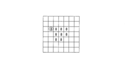
- FIG. 11A shows an example of gradient data stored in the gradient data storage unit 12.
- the vertex pixel is located at the center, and a gradient label is assigned to each of the surrounding pixels located around the vertex pixel.
- vertex pixels are indicated by “x” marks, and gradient labels are schematically indicated by arrows, similar to the gradient data shown in FIG. 1B.
- the area label generation unit 16 and the vertex label of the vertex pixel positioned at the input vertex coordinate and the surroundings thereof The gradient data of the surrounding pixels for 8 pixels is read from the gradient data storage unit 12. Then, the region label generation unit 16 determines whether or not the gradient labels assigned to the read gradient data of the eight neighboring pixels represent the gradient direction toward the read vertex pixel. In the example shown in FIG. 11B, the gradient data of the peripheral pixels at the lower right of the vertex pixel among the gradient data of the eight peripheral pixels indicates the gradient direction toward the vertex pixel.
- the region label generation unit 16 assigns a region label having the same value as the vertex label of the vertex pixel to each of the peripheral pixels corresponding to the gradient data representing the gradient direction toward the vertex pixel.
- the same value as the vertex label of the vertex pixel here, circled
- the state of “8”) is given.
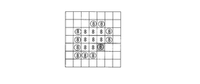
- the area label generation unit 16 sequentially reads the gradient data of the surrounding pixels for the surrounding 8 pixels from the gradient data storage unit 12 with the surrounding pixels assigned with the same area label as the center sequentially, It is determined whether or not the gradient label assigned to each pixel gradient data represents the gradient direction toward the peripheral pixel at the center.
- FIG. 11D a case is shown in which gradient data of peripheral pixels for eight peripheral pixels is read from the gradient data storage unit 12 around the peripheral pixel surrounded by a circle located at the upper right of the vertex pixel. Yes.
- only the gradient data of the peripheral pixel at the left center among the read gradient data of the eight peripheral pixels indicates a state in which the gradient direction toward the peripheral pixel is the center. Yes.
- the region label generation unit 16 assigns a region label having the same value as the region label assigned to the central peripheral pixel to each of the peripheral pixels corresponding to the gradient data representing the gradient direction toward the central peripheral pixel. .
- a region label having the same value here, “8” surrounded by a circle
- the same value is applied to the lower right peripheral pixel (peripheral pixel represented by shading) that is determined not to be a peripheral pixel that represents the gradient direction toward the vertex pixel in FIG. 11B.
- the area label is assigned.
- the peripheral pixel at the lower right of the vertex pixel is This is because it is determined that the gradient direction toward the peripheral pixel at the lower center is represented.
- the region label generation unit 16 determines whether or not each peripheral pixel newly assigned with the same region label is sequentially centered, and represents a gradient direction toward the peripheral pixel as the center, A region label having the same value is assigned to the peripheral pixel determined to represent the gradient direction toward the peripheral pixel at the center.
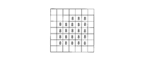
- the region label generation unit 16 sequentially expands the region for determining the gradient direction from the vertex pixel located at the center, and finally, all the peripheral pixels have the gradient direction toward the central peripheral pixel. If it is determined that the pixel is not represented, the process of assigning a region label to peripheral pixels belonging to the same vertex pixel, that is, the region label generation process is terminated.
- FIG. 11G a region label is assigned according to the result of determining the gradient direction with the surrounding pixels circled in FIG. 11F as the center in order, and the vertex pixel (FIG. 11A, FIG. 11B, and FIG. 2 shows an example of final region label data for which region label generation processing for the vertex pixel indicated by “x” in FIG.
- the gradient data reading source address generation unit 161 assigns a region label to each peripheral pixel belonging to the vertex pixel corresponding to the vertex coordinate assigned by the vertex coordinate distribution unit 15, so that the gradient label or vertex is supplied from the gradient data storage unit 12.
- a gradient data reading source address for reading a label is generated.
- the gradient data reading source address generation unit 161 outputs the generated gradient data reading source address to the gradient data storage unit 12, and the gradient label or vertex label stored in the storage area corresponding to the gradient data reading source address Is output to the outermost periphery data gradient determination unit 162. Further, the gradient data reading source address generation unit 161 outputs the generated gradient data reading source address to the outermost circumference data gradient determination unit 162.
- the gradient data reading source address generation unit 161 generates another gradient data reading source address based on the gradient determination result input from the outermost periphery data gradient determination unit 162, and the gradient data storage unit 12 and the The data is output to the outer circumference data gradient determination unit 162.
- the outermost circumference data gradient determination unit 162 applies the same vertex pixel based on the gradient data reading source address input from the gradient data reading source address generation unit 161 and the gradient label and vertex label input from the gradient data storage unit 12. Each surrounding pixel to which it belongs is determined. Then, the outermost periphery data gradient determination unit 162 indicates the gradient data reading source address of the peripheral pixels determined to belong to the same vertex pixel, and the gradient determination result representing the coordinates representing the positions of the peripheral pixels determined to belong to the same vertex pixel Is output to the gradient data reading source address generation unit 161. As a result, the gradient data reading source address generation unit 161 reads out another gradient label.
- the outermost peripheral data gradient determination unit 162 generates an area label write destination address that represents the position of each peripheral pixel belonging to the same vertex pixel, and corresponds to the generated area label write destination address and the area label write destination address.
- the area label to be stored in the storage area is output to the area label storage unit 17.
- the corresponding area label is stored in the storage area corresponding to the area label write destination address of the area label storage unit 17.
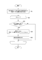
- FIG. 13 is a flowchart illustrating a processing procedure in the gradient data reading source address generation unit 161 provided in the image processing apparatus 1 according to the first embodiment of the present invention.
- the gradient data storage unit 12 stores the gradient data (vertex label) of the vertex pixels stored in the storage area designated by the gradient data reading source address and the surrounding pixels for 8 pixels located around the vertex pixels.
- the gradient data (gradient label) is output to the outermost circumference data gradient determination unit 162.
- the gradient data reading source address generation unit 161 outputs the generated gradient data reading source address to the outermost periphery data gradient determination unit 162.
- the outermost peripheral data gradient determination unit 162 determines peripheral pixels representing the gradient direction toward the vertex pixel by a processing procedure described later, and outputs the gradient determination result to the gradient data reading source address generation unit 161.
- the gradient data reading source address generation unit 161 acquires the gradient determination result output from the outermost periphery data gradient determination unit 162, that is, the coordinates representing the positions of surrounding pixels determined to belong to the same vertex pixel ( Step S42).
- the gradient data reading source address generation unit 161 stores the coordinates of each peripheral pixel included in the gradient determination result (step S43). In addition, the gradient data reading source address generation unit 161 stores the number of coordinates of the peripheral pixels included in the gradient determination result (step S44). For example, as shown in FIG. 11B, the gradient determination result indicates a gradient direction toward the vertex pixel other than the gradient data of the lower right peripheral pixel of the vertex pixel among the gradient data of the eight peripheral pixels. If it is, the gradient data reading source address generation unit 161 stores “7” as the number of coordinates of the peripheral pixels in the process of step S44.
- the gradient data reading source address generation unit 161 sets a gradient data reading source address for reading gradient data of peripheral pixels for eight pixels located around the peripheral pixel of the read coordinates.
- the generated gradient data reading source address is output to the gradient data storage unit 12 (step S47).
- the gradient data reading source address generation unit 161 reads gradient data of peripheral pixels for eight neighboring pixels centered on any one of the peripheral pixels.
- a reading source address is generated and output to the gradient data storage unit 12.
- the gradient data reading source address generation unit 161 outputs the generated gradient data reading source address to the outermost periphery data gradient determination unit 162.
- the gradient data storage unit 12 converts the gradient data (gradient label) of the surrounding pixels stored in the storage area specified by the gradient data reading source address to the outermost periphery data, as in the process of step S41.
- the outermost peripheral data gradient determination unit 162 similarly determines a peripheral pixel representing a gradient direction toward the peripheral pixel as a center by a processing procedure described later, and generates a new gradient determination result as a gradient data reading source address. To the unit 161.
- the gradient data reading source address generation unit 161 represents the new gradient determination result output from the outermost periphery data gradient determination unit 162, that is, the positions of the outer peripheral pixels determined to belong to the same vertex pixel.
- the coordinates are acquired (step S48).
- the gradient data reading source address generation unit 161 stores the coordinates of each peripheral pixel included in the gradient determination result (step S49).
- the coordinates of the peripheral pixels stored in the process of step S49 are stored in addition to the coordinates of the peripheral pixels stored in the process of step S43.
- a first-in first-out (FIFO) type storage area can be considered as the storage area for storing the coordinates of the peripheral pixels.
- the storage area that stores the coordinates of the peripheral pixels in the process of step S49 may be a storage area that is different from the storage area that stores the coordinates of the peripheral pixels in the process of step S43.
- the outermost periphery data gradient determination unit 162 receives the gradient data (vertex label) of the vertex pixel corresponding to the gradient data reading source address from the gradient data storage unit 12, and the gradient of the surrounding pixels for eight pixels located around the vertex pixel. Receive data (gradient label). Further, the outermost periphery data gradient determination unit 162 receives the gradient data reading source address generated by the gradient data reading source address generation unit 161 as coordinates representing the positions of the vertex pixel and the surrounding pixels (step S51).
- the outermost periphery data gradient determination unit 162 outputs coordinates representing the positions of surrounding pixels that output the region label to the gradient data reading source address generation unit 161 as a gradient determination result (step S55). Then, the outermost periphery data gradient determination unit 162 performs the loop process of step S52 for any one of the following surrounding pixels.
- the outermost peripheral data gradient determination unit 162 performs gradient direction determination processing on each of the received gradient data of the surrounding pixels for eight pixels.
- the region to which the region label is assigned to the peripheral pixels that belong to the same vertex pixel is sequentially expanded, and finally the region as shown in FIG.
- the label data is stored in the area label storage unit 17.
- the region label generation unit 16 performs region division processing for assigning the same region label to peripheral pixels belonging to the same vertex pixel. In this region division processing, the region label generation unit 16 assigns region labels so as to spread from the vertex pixels to the surrounding pixels. For this reason, each of the plurality of region label generation units 16 included in the image processing apparatus 1 can perform region division processing on different vertex pixels in parallel. In the image processing apparatus 1, it is possible to reduce the overall processing time expected according to the number of area label generation units 16 provided in the image processing apparatus 1.
- the processing procedure of the outermost periphery data gradient determination unit 162 shown in FIG. 14 is executed corresponding to step S41 of the processing procedure of the gradient data reading source address generation unit 161 shown in FIG.
- the processing procedure shown in FIG. 14 is executed corresponding to each of steps S41 and S47 of the processing procedure of the gradient data reading source address generation unit 161 shown in FIG.
- the outermost circumference data gradient determination unit 162 determines that the previous FIG. The gradient data and coordinates when the peripheral pixel determined to belong to the same vertex pixel by the processing procedure shown in FIG.
- the outermost periphery data gradient determination unit 162 determines that the region label having the same value as the region label output in the processing of step S54 of the previous processing procedure shown in FIG. 17 to output.
- the luminance value is higher than the first label (gradient label) indicating a direction toward a pixel having a higher luminance value, or all pixels (peripheral pixels) located in the vicinity.
- a gradient data generation unit (gradient data generation unit 11) that generates gradient data representing each pixel included in the luminance image with a second label (vertex label) having a value indicating high, and expressed by a vertex label
- Each of the noted pixels is a vertex pixel, and the area in the luminance image is divided into areas containing pixels (peripheral pixels) belonging to the same vertex pixel based on the vertex coordinates representing the position of the vertex pixel, and the divided area Included in it
- a plurality of region label generation units (region label generation unit 16) for generating region label data in which the peripheral pixels are represented by third labels (region labels) having values indicating pixels belonging to the same vertex pixel;
- Each area label generation unit 16 determines each of the target vertex pixels to be calculated so that the load of the calculation for dividing the area in the luminance image into areas including peripheral pixels belonging to the same vertex pixel is equalized.
- an image processing device image processing device 1 including a vertex pixel distribution unit (vertex coordinate distribution
- the vertex pixel distribution unit (vertex coordinate distribution signal generation unit 14) is positioned in a region within a predetermined range from the center vertex pixel when the vertex pixel is the center.
- a region area estimation unit (region area estimation unit 141) that estimates a region area representing the size of a region of peripheral pixels belonging to the center vertex pixel based on the number of other vertex pixels Then, based on each area area, each vertex pixel is assigned to each area label generation unit 16 so that the difference in area area corresponding to the vertex pixel to be calculated is minimized, and the assigned area label
- a vertex coordinate distribution scheduling unit (vertex coordinate distribution scheduling unit 143) for assigning a distribution signal representing the generation unit 16 to the vertex coordinates corresponding to each vertex pixel; Based on the distribution signal given to the point coordinates, an image processing apparatus 1 is provided that includes a vertex coordinate distribution unit (vertex coordinate distribution unit 15) that outputs vertex coordinates to the region label generation unit 16 represented by the distribution signal. .
- the area area estimation unit 141 calculates the distance between two vertex pixels based on the vertex coordinates of the vertex pixel as the center and the vertex coordinates of the other vertex pixels, respectively. Based on the calculated distance between the two vertex pixels, the number of other vertex pixels existing in an area (threshold area) within a predetermined distance from the center vertex pixel position is counted.
- the image processing apparatus 1 is configured to estimate the area of the area corresponding to each vertex pixel using the inverse of the counted number of other vertex pixels.
- the vertex coordinate distribution scheduling unit 143 includes the image processing device 1 that allocates the vertex pixels to each of the region label generation units 16 in a predetermined order.
- the vertex coordinate distribution scheduling unit 143 includes a sorting unit (sorting unit 1431) that rearranges each vertex pixel in a predetermined order based on the corresponding area area.
- the image processing apparatus 1 is configured in which the vertex pixels after the sorting unit 1431 has been rearranged are assigned to the region label generation unit 16.
- the vertex coordinate distribution scheduling unit 143 assigns vertex pixels to the region label generation unit 16 so that the order of the plurality of region label generation units 16 alternately repeats ascending order and descending order.
- An image processing apparatus 1 assigned to each is configured.
- each of the region label generation units 16 is centered on the vertex pixel corresponding to the vertex coordinates, and each gradient representing each pixel (peripheral pixel) located around the vertex pixel.
- the gradient data acquisition unit (gradient data reading source address generation unit 161) for acquiring data and the value of the gradient label representing each peripheral pixel included in the acquired gradient data are values indicating the direction toward the vertex pixel.
- Gradient determination that generates region label data that represents the surrounding pixels represented by the gradient label of the value indicating the direction toward the vertex pixel with the region label having the same value as the vertex label value representing the vertex pixel is configured.
- the gradient data reading source address generation unit 161 sequentially expands the peripheral pixel regions centered sequentially from the position of the vertex coordinate corresponding to the vertex pixel to the peripheral pixels on the outer periphery.
- each gradient data representing each peripheral pixel is acquired, and the outermost circumference data gradient determination unit 162 corresponds to the vertex pixel in the region represented by the region label having the same value as the vertex label representing the vertex pixel.
- the image processing apparatus 1 is configured to generate region label data that sequentially spreads from the position of the vertex coordinates to the peripheral pixels on the outer periphery.
- the vertex coordinate distribution signal generation unit 14 calculates the sum of the calculation loads of the region label generation units 16, that is, each region label generation unit 16 stores the region label.
- a distribution signal indicating the allocation of the region label generation unit 16 is given in advance to the vertex coordinates of the vertex pixel to be calculated so that the total area of the regions of the peripheral pixels to which is given is substantially equal.
- the vertex coordinate distribution unit 15 distributes each vertex coordinate to the corresponding region label generation unit 16 based on the distribution signal given to the vertex coordinate ( Distribute). Thereby, each area label generation unit 16 can be operated without being idle, and the overall processing time in the image processing apparatus 1 can be shortened.
- FIG. 15A to FIG. 15D are diagrams for explaining another method of giving a distribution signal by the vertex coordinate distribution scheduling unit 143 provided in the image processing apparatus 1 according to the first embodiment of the present invention.
- 15A to 15C as in FIGS. 9A to 9C, the horizontal axis represents the arrangement of the vertex coordinates, and the vertical axis represents the size of the area estimated at each vertex coordinate.
- the horizontal axis represents each region label generation unit 16
- the vertical axis represents the computation load assigned to each region label generation unit 16 by the size of the region area. ing.
- FIGS. 15A and 15B are the same as FIGS. 9A and 9B, and a detailed description thereof will be omitted.
- the vertex coordinates assigned to the region label generation unit 16-0 having a large total area are reassigned to the region label generation unit 16-1 and the region label generation unit 16-2 having a small total area.
- An example of the case is shown.
- the vertex coordinate distribution scheduling unit 143 changes (corrects) the assignment of the vertex coordinates to each region label generation unit 16 after giving the distribution signal, as shown in FIG.
- the sum of the area areas estimated with respect to the vertex coordinates assigned to the area label generation unit 16 becomes more even, and each area label generation unit 16 can be operated more efficiently.
- the vertex coordinate distribution scheduling unit 143 has the smallest sum of the largest area areas among the sum of the area areas allocated to the respective area label generation units 16. The difference from the sum of the area areas is divided by the number of area label generation sections 16, and the vertex label corresponding to the area area corresponding to the area area as a result of the division is determined as the area label generation section 16 having the largest total area area.
- the image processing device 1 is reassigned to each of the area label generation units 16 other than the above.
- FIG. 17 is a flowchart showing another processing procedure in the area area estimation unit 141 provided in the image processing apparatus 1 according to the first embodiment of the present invention.
- a plurality of area areas ⁇ (hereinafter referred to as “estimated area areas ⁇ ”) are discretely set as threshold values for the predetermined area areas.
- the area area estimation unit 141 compares the number of vertex pixels existing in the threshold area with the number of vertices represented by the reciprocal of the estimated area area ⁇ , thereby determining the area area belonging to each vertex pixel as the estimated area. It is estimated to be any one of the areas ⁇ .
- n estimated area areas ⁇ (estimated area area ⁇ 0 to estimated area area ⁇ n , ⁇ 0 > ⁇ n ) are set.
- the area area is estimated to be one of the estimated area areas ⁇ after the detection of the number of vertex pixels existing in the threshold area is completed.
- region area estimation unit 141 determines the number of the detected vertex pixels, or less or not than the reciprocal of the estimated region area theta 1 (number of vertices corresponding to the estimated region area theta 1) (step S63) .
- step S63 the number of the detected vertex pixels, if it is determined that less than the number of vertices corresponding to the estimated region area ⁇ 1 ( "YES" in step S63), region area estimation unit 141, in step S64, the area The area is estimated to be equivalent to the estimated area area ⁇ 1 .
- step S63 the number of the detected vertex pixels, the estimated region area theta not less than the number of vertices corresponding to 1, that is, more than the number of vertices in the number of detected apex pixels corresponding to the estimated region area theta 1 If it is determined that there is (“NO” in step S63), the area area estimation unit 141 proceeds to the process of step S65.
- region area estimation unit 141 determines the number of the detected vertex pixels, or less or not than the reciprocal of the estimated region area ⁇ n-1 (the number of vertices corresponding to the estimated region area ⁇ n-1) (Step S65). If it is determined in step S65 that the number of detected vertex pixels is smaller than the number of vertices corresponding to the estimated area area ⁇ n ⁇ 1 (“YES” in step S65), the area area estimating unit 141 determines in step S66. The region area is estimated to be equal to the estimated region area ⁇ n ⁇ 1 .
- the area area estimation unit 141 also uses the reciprocal of the predetermined estimated area area ⁇ (the number of vertices corresponding to the estimated area area ⁇ ) as a threshold value, and compares it with the number of detected vertex pixels. Can be simply estimated for each predetermined range.
- the area area estimation unit 141 includes the number of other vertex pixels located in a region within a predetermined range from the central vertex pixel, and a plurality of predetermined vertex pixels.
- the area area corresponding to each vertex pixel is estimated to be one of a plurality of predetermined estimated area areas ⁇ based on the threshold value of the area area (estimated area area ⁇ ).
- An image processing apparatus 1 is configured.
- the vertex coordinate distribution signal generation unit 14 is connected to the vertex coordinate distribution scheduling unit 143 in the vertex coordinate distribution signal generation unit 14 as illustrated in FIG. 9 or FIG.
- the configuration has been described in which the sorting unit 1431 provided rearranges (sorts) the vertex coordinates in a predetermined order, and the distribution signal providing unit 1433 assigns the respective vertex coordinates to the area label generation unit 16 in accordance with this order.
- the configuration in which the vertex coordinate distribution signal generation unit 14 assigns each vertex coordinate to the region label generation unit 16 is the configuration shown in FIG. 5, that is, the configuration that performs the processing shown in FIGS. 9 to 10 and FIG. It is not limited to.
- FIG. 18 is a block diagram illustrating another configuration of the vertex coordinate distribution signal generation unit 14 included in the image processing apparatus 1 according to the first embodiment of the present invention.
- the vertex coordinate distribution signal generation unit 14a illustrated in FIG. 18 includes a region area estimation unit 141a, a region area storage unit 142a, and a vertex coordinate distribution scheduling unit 143a.
- the area area estimation unit 141 a is based on the respective vertex coordinates stored in the vertex coordinate storage unit 13, and the area area of peripheral pixels belonging to each vertex pixel included in the luminance image Is simply estimated. Then, the area area estimation unit 141a uses the estimated area area information of surrounding pixels belonging to each vertex pixel as the address of the area area storage unit 142a, and stores the vertex coordinates of each vertex pixel in the area area storage unit 142a. The data is output to the area area storage unit 142a.
- the vertex coordinate distribution scheduling unit 143a sequentially reads out the vertex coordinates of each vertex pixel stored in each memory space of the region area storage unit 142a in a predetermined order, and performs an operation on each read vertex pixel. It assigns to each of the label production
- the order in which the vertex coordinate distribution scheduling unit 143a reads the vertex coordinates of each vertex pixel realizes the same function as the sort unit 1431 provided in the vertex coordinate distribution scheduling unit 143.
- the order in which the vertex coordinate distribution scheduling unit 143a reads the vertex coordinates of each vertex pixel is determined from the memory space (space for the estimated region area ⁇ n ) corresponding to the estimated region area ⁇ n having the smallest region area.
- the order of the area of the regions may be reduced, that is, in descending order.
- the vertex coordinate distribution scheduling unit 143a gives a distribution signal to the read vertex coordinates so that the sum of the calculation loads performed by each of the area label generation units 16 is substantially equal. And output to the vertex coordinate distribution unit 15.
- the region area estimation unit (region area storage unit 142a) estimates the region area corresponding to each vertex pixel
- the estimated vertex pixel is calculated.
- the vertex coordinate distribution scheduling unit assigns the rearranged vertex pixels to each of the area label generation units 16 in a predetermined order. Is configured.
- the image processing apparatus of the second embodiment includes, for example, a plurality of luminance image areas such as grayscale images.
- An image processing apparatus that divides and performs region division processing in parallel with a plurality of calculation resources is the same as the concept of area division processing in the image processing apparatus 1 of the first embodiment shown in FIG. Therefore, a detailed description of the concept of the area division process performed by the image processing apparatus 2 of the second embodiment is omitted.
- FIG. 19 is a block diagram showing an example of a schematic configuration of the image processing apparatus 2 according to the second embodiment of the present invention.
- the image processing apparatus 2 shown in FIG. 2 includes a gradient data generation unit 11b, a gradient data storage unit 12, a vertex coordinate distribution signal generation unit 14b, a vertex coordinate distribution unit 15, and n region label generation units 16- 1 to a region label generation unit 16-n and a region label storage unit 17 are provided.
- the gradient data generation unit 11b generates gradient data corresponding to the input luminance image, similarly to the gradient data generation unit 11 included in the image processing apparatus 1 of the first embodiment, and the generated gradient data is converted into gradient data.
- the data is output to the storage unit 12.
- the gradient data generation unit 11b does not output the vertex coordinates output in the gradient data generation unit 11 provided in the image processing apparatus 1 of the first embodiment. Since other operations in the gradient data generation unit 11b are the same as those in the gradient data generation unit 11 of the first embodiment, a detailed description regarding the operation of the gradient data generation unit 11b is omitted.
- the vertex coordinate distribution signal generation unit 14b assigns region labels to peripheral pixels belonging to the same vertex pixel in the luminance image based on the vertex label assigned to the vertex pixel included in the gradient data stored in the gradient data storage unit 12.
- the calculation to be assigned is distributed to each calculation resource provided in the image processing apparatus 2.
- the vertex coordinate distribution signal generation unit 14b uses the vertex coordinate distribution unit 15 as a result of distributing the calculation to the calculation resources. Output to.
- the vertex coordinate distribution signal generation unit 14b detects the position of the vertex pixel to which the vertex label is assigned from the gradient data read from the gradient data storage unit 12. Then, the vertex coordinate distribution signal generation unit 14b uses the coordinates representing the position of the detected vertex pixel as the vertex coordinates, and exists within a predetermined unit area centered on the position of the detected vertex pixel based on the vertex coordinates. The area area of the peripheral pixels belonging to each vertex pixel is simply estimated from the number of other vertex pixels assigned the vertex label. Then, the vertex coordinate distribution signal generation unit 14b performs an operation on each vertex pixel based on the estimated area area, similarly to the vertex coordinate distribution signal generation unit 14 included in the image processing apparatus 1 of the first embodiment. A vertex coordinate to which a computation resource to be assigned is assigned and a distribution signal indicating the assigned computation resource is assigned is output to the vertex coordinate distribution unit 15.
- the area area estimation unit 141b sequentially reads the gradient data stored in the gradient data storage unit 12 in the loop of step S72 in the raster order and detects the gradient data of the vertex pixel, the position of the vertex pixel is detected.
- the vertex density is obtained by counting the number of other vertex pixels existing in the rectangular threshold region centered at. Thereby, the area area estimation unit 141b can obtain the vertex density corresponding to the number of vertex pixels stored in the gradient data storage unit 12.
- the vertex coordinate distribution signal generation unit 14b has the calculation load of each region label generation unit 16 as in the image processing device 1 of the first embodiment.
- a distribution signal indicating the allocation of the region label generation unit 16 is given in advance to the vertex coordinates of the target vertex pixel to be calculated so that the sum is substantially equal.
- the area area estimation unit 141b provided in the vertex coordinate distribution signal generation unit 14b obtains the vertex density corresponding to each vertex pixel in order to estimate the area area.
- the number of other vertex pixels existing in the rectangular threshold region centered on the vertex pixel detected from the gradient data is counted.
- the image processing device 2 of the second embodiment when the number m of gradient data existing in the rectangular threshold region is smaller than the number n of all vertex pixels included in the gradient data, the first Compared to the image processing apparatus 1 of the first embodiment, the calculation cost required for estimating the area of the area is reduced, and the entire processing time of the area division processing in the image processing apparatus 2 can be shortened.
- the area area estimation unit 141 is the same as the area area estimation unit 141 in the vertex coordinate distribution signal generation unit 14 included in the image processing apparatus 1 of the first embodiment. However, the area area estimation unit 141 in the vertex coordinate distribution signal generation unit 14c provided in the image processing apparatus 3 associates information on the simply estimated area area (reciprocal of vertex density) with each vertex coordinate. And sequentially output to the vertex coordinate distribution scheduling unit 143c.
- FIG. 23A vertex coordinates associated with region area information (reciprocal of vertex density) are sequentially input to the vertex coordinate distribution scheduling unit 143c from the region area estimation unit 141 (in time series). Is done.
- the vertex coordinate distribution scheduling unit 143c sequentially assigns the input vertex coordinates to the region label generation unit 16 in sequence.
- FIG. 23B shows a state in which the first to third vertex coordinates input from the area area estimation unit 141 are sequentially assigned to the area label generation unit 16-0 to the area label generation unit 16-2, respectively. Show. More specifically, the first vertex coordinate is set to the region label generation unit 16-0, the second vertex coordinate is set to the region label generation unit 16-1, and the third vertex coordinate is set to the region label generation unit 16. -2 shows the assigned state.
- the vertex coordinate distribution scheduling unit 143c is sequentially input from the region area estimation unit 141 when assigning the fourth and subsequent vertex coordinates to any of the region label generation unit 16-0 to the region label generation unit 16-2.
- the assigned vertex coordinates are assigned to the area label generation unit 16 with the least computational load at that time.
- FIG. 23C shows a state in which the fourth vertex coordinate input from the area area estimation unit 141 is assigned to the area label generation unit 16-2 with the least calculation load in the previous stage (see FIG. 23B). ing.
- the vertex coordinate distribution scheduling unit 143c receives the first vertex coordinate associated with the area area information (reciprocal of the vertex density) (step S81). The vertex coordinate distribution scheduling unit 143c determines whether there is an area label generation unit 16 to which no vertex coordinate is assigned (step S82).
- step S81 when the next vertex coordinate associated with the area area information (reciprocal of vertex density) is received in step S81, and it is determined in step S82 that there is no area label generation unit 16 to which no vertex coordinate is assigned. ("NO" in step S81), the vertex coordinate distribution scheduling unit 143c performs distribution signal provision processing represented by a loop in step S85.
- step S87 the vertex coordinate distribution scheduling unit 143c assigns a distribution signal representing the area label generation unit 16-1 to the received fifth vertex coordinate, and the fifth vertex coordinate to which the distribution signal is added. Is output to the vertex coordinate distribution unit 15.
- the vertex coordinate distribution scheduling unit 143c in step S86, as shown in FIG. 23D, the accumulated region area corresponding to the region label generation unit 16-0. In the buffer [0], the value of the size of the area area belonging to the vertex pixel corresponding to the sixth vertex coordinate is added and stored.
- step S87 the vertex coordinate distribution scheduling unit 143c adds a distribution signal representing the region label generation unit 16-0 to the received sixth vertex coordinate, and the sixth vertex coordinate to which the distribution signal is added. Is output to the vertex coordinate distribution unit 15.
- the vertex coordinate distribution scheduling unit (vertex coordinate distribution scheduling unit 143c) sequentially assigns vertex pixels to the region label generation unit (region label generation unit 16) to which no vertex pixel is allocated,
- an image processing device (image processing device 3) that sequentially assigns vertex pixels to the region label generation unit 16 having the smallest sum of the assigned region areas is configured. Is done.
- each embodiment of the present invention the configuration of an image processing apparatus provided with different components for each embodiment is shown.
- each embodiment is not an exclusive configuration, and the configuration shown in each embodiment may be included in the image processing apparatus having any configuration shown in each embodiment.
- the vertex coordinate distribution scheduling unit 143 and the vertex coordinate distribution scheduling unit 143c have described several methods (distribution signal applying process) in which the vertex coordinates are allocated to the region label generation unit 16.
- the method of assigning vertex coordinates to the area label generation unit 16 is not limited to the method shown in each embodiment.
- the pixel position is represented by coordinates such as vertex coordinates.
- the information representing the pixel position is limited to the coordinates shown in each embodiment. Is not to be done.
- the image processing apparatus when performing computation in parallel with a plurality of computation resources for the purpose of shortening the processing time in the area division processing, the respective computation resources are operated without being idle, Overall processing time can be shortened.
Landscapes
- Engineering & Computer Science (AREA)
- Theoretical Computer Science (AREA)
- Physics & Mathematics (AREA)
- General Physics & Mathematics (AREA)
- Computer Vision & Pattern Recognition (AREA)
- Software Systems (AREA)
- General Engineering & Computer Science (AREA)
- Geometry (AREA)
- Image Analysis (AREA)
- Image Processing (AREA)
Abstract
入力された画像に含まれるそれぞれの画素に順次注目し、注目した画素の輝度値と、注目した画素の周囲に位置する他の画素の輝度値とに基づいて、輝度値が高い画素に向かう方向を示す値の第1のラベル、または周囲に位置する全ての画素よりも輝度値が高いことを示す値の第2のラベルで、画像に含まれるそれぞれの画素を表した勾配データを生成する勾配データ生成部と、第2のラベルで表された画素のそれぞれを頂点画素とし、頂点画素の位置を表す頂点座標に基づいて、画像内の領域を、同じ頂点画素に属する画素が含まれる領域に分割し、分割した領域に含まれるそれぞれの画素を、同じ頂点画素に属する画素であることを示す値の第3のラベルで表した領域ラベルデータを生成する複数の領域ラベル生成部と、それぞれの領域ラベル生成部が、画像内の領域を同じ頂点画素に属する画素が含まれる領域に分割する演算の負荷が均等になるように、演算を行う対象の頂点画素のそれぞれを、領域ラベル生成部のそれぞれに分配する頂点画素分配部と、を備える。
Description
本発明は、画像処理装置に関する。
従来から、処理時間がデータの量に依存するような画像処理がある。このため、画像処理装置に備えた複数の演算リソースのそれぞれが行う演算負荷が均等になるようにデータを分配し、それぞれの演算リソースによる演算を並列に行うことによって全体の処理時間の短縮を図る方法が提案されている。
例えば、特許文献1には、ボリュームデータを構成するボクセルのうち、表示対象物を投影したときの投影面側から見える表面に位置する表面ボクセルの個数がほぼ均等になるように分割することによって、それぞれの演算リソースを遊休させることなく稼働させる3次元画像生成装置の技術が開示されている。
一方、画像処理の分野には、画像データを輝度値などのデータに基づいて複数の領域に分割する領域分割処理と呼ばれる処理がある。この領域分割処理は、例えば、細胞の解析など、様々な分野で応用されている。
しかしながら、特許文献1に開示された技術は、X線CT(Computed Tomography)装置などによって計測された人体などの画像をボリュームレンダリングで処理して描画(表示)する方法の技術である。そして、特許文献1に開示された技術では、人体内の組織の不透明度などに閾値を設定し、不透明度の値が閾値以上である組織を表示対象物として定めることによって、表示対象物が存在する範囲が決定され、三次元の画像を生成する際の計算量の推定が可能となることに着目している。つまり、特許文献1に開示された技術は、ボリュームレンダリングの処理に特有の計算量を推定方法に関する技術である。なお、特許文献1には、演算負荷がほぼ均等になるように、推定した計算量に基づいて処理をそれぞれの演算リソースに割り当てる具体的な方法に関しては、開示されてない。
このため、特許文献1に開示された技術を、領域分割処理における演算負荷の推定にそのまま適用することは困難である。つまり、例えば、グレースケール画像などに対する領域分割処理では、特許文献1に開示された技術による演算負荷の推定を行うことができない。
本発明は、上記の課題に基づいてなされたものであり、領域分割処理にける処理時間の短縮を目的として複数の演算リソースで並列に演算を行う場合に、それぞれの演算リソースを遊休させることなく稼働させ、全体の処理時間を短縮することができる画像処理装置を提供することを目的としている。
本発明の第1の態様の画像処理装置は、入力された画像に含まれるそれぞれの画素に順次注目し、注目した前記画素の輝度値と、注目した前記画素の周囲に位置する他の前記画素の輝度値とに基づいて、輝度値が高い前記画素に向かう方向を示す値の第1のラベル、または周囲に位置する全ての前記画素よりも輝度値が高いことを示す値の第2のラベルで、前記画像に含まれるそれぞれの前記画素を表した勾配データを生成する勾配データ生成部と、前記第2のラベルで表された前記画素のそれぞれを頂点画素とし、前記頂点画素の位置を表す頂点座標に基づいて、前記画像内の領域を、同じ前記頂点画素に属する前記画素が含まれる領域に分割し、分割した前記領域に含まれるそれぞれの前記画素を、同じ前記頂点画素に属する前記画素であることを示す値の第3のラベルで表した領域ラベルデータを生成する複数の領域ラベル生成部と、それぞれの前記領域ラベル生成部が、前記画像内の領域を同じ前記頂点画素に属する前記画素が含まれる領域に分割する演算の負荷が均等になるように、演算を行う対象の前記頂点画素のそれぞれを、前記領域ラベル生成部のそれぞれに分配する頂点画素分配部と、を備える。
本発明の第2の態様によれば、上記第1の態様の画像処理装置において、前記頂点画素分配部は、前記頂点画素を中心としたときに、中心とした前記頂点画素から予め定めた範囲内の領域に位置する他の前記頂点画素の数に基づいて、中心とした前記頂点画素に属する前記画素の領域の大きさを表す領域面積を、それぞれの前記頂点画素ごとに推定する領域面積推定部と、それぞれの前記領域面積に基づいて、演算を行う対象の前記頂点画素に対応する前記領域面積の差が最小になるように、それぞれの前記頂点画素を前記領域ラベル生成部のそれぞれに割り当て、割り当てた前記領域ラベル生成部を表す分配信号を、それぞれの前記頂点画素に対応する前記頂点座標に付与する頂点座標分配スケジューリング部と、それぞれの前記頂点座標に付与された前記分配信号に基づいて、前記分配信号が表す前記領域ラベル生成部に前記頂点座標を出力する頂点座標分配部と、を備えてもよい。
本発明の第3の態様によれば、上記第2の態様の画像処理装置において、前記領域面積推定部は、中心とした前記頂点画素の前記頂点座標と、他の前記頂点画素の前記頂点座標とに基づいて、2つの前記頂点画素の間の距離をそれぞれ算出し、算出した2つの前記頂点画素の間の距離に基づいて、中心とした前記頂点画素の位置から予め定めた距離の範囲内の領域に存在する他の前記頂点画素の数を計数し、計数した他の前記頂点画素の数の逆数を用いて、それぞれの前記頂点画素に対応する前記領域面積を推定してもよい。
本発明の第4の態様によれば、上記第2の態様または上記第3の態様の画像処理装置において、前記領域面積推定部は、中心とした前記頂点画素から予め定めた範囲内の領域に位置する他の前記頂点画素の数と、予め定めた複数の領域面積の閾値で表される前記頂点画素の数とに基づいて、それぞれの前記頂点画素に対応する前記領域面積を、前記予め定めた複数の前記領域面積の前記閾値のいずれかに推定してもよい。
本発明の第5の態様によれば、上記第2の態様から上記第4の態様のいずれか一態様の画像処理装置において、前記頂点座標分配スケジューリング部は、前記頂点画素を、予め定めた順番で前記領域ラベル生成部のそれぞれに割り当ててもよい。
本発明の第6の態様によれば、上記第5の態様の画像処理装置において、前記頂点座標分配スケジューリング部は、対応する前記領域面積に基づいて、それぞれの前記頂点画素を予め定めた順番に並び替えるソート部、を備え、前記ソート部が並び替えた後の前記頂点画素を、前記領域ラベル生成部のそれぞれに割り当ててもよい。
本発明の第7の態様によれば、上記第4の態様の画像処理装置において、前記領域面積推定部は、それぞれの前記頂点画素に対応する前記領域面積を推定する際に、推定したそれぞれの前記頂点画素を予め定めた順番に並び替え、前記頂点座標分配スケジューリング部は、並び替えた後の前記頂点画素を、予め定めた順番で前記領域ラベル生成部のそれぞれに割り当ててもよい。
本発明の第8の態様によれば、上記第5の態様から上記第7の態様のいずれか一態様の画像処理装置において、前記頂点座標分配スケジューリング部は、複数の前記領域ラベル生成部の順番が昇順と降順とを交互に繰り返すように、前記頂点画素を、前記領域ラベル生成部のそれぞれに割り当ててもよい。
本発明の第9の態様によれば、上記第5の態様から上記第8の態様のいずれか一態様の画像処理装置において、前記頂点座標分配スケジューリング部は、それぞれの前記領域ラベル生成部に割り当てられた前記領域面積の総和の内、最も大きい前記領域面積の総和と最も小さい前記領域面積の総和との差を、前記領域ラベル生成部の数で除算し、除算した結果の領域面積に相当する前記領域面積に対応する前記頂点画素を、前記領域面積の総和が最も大きい前記領域ラベル生成部以外の前記領域ラベル生成部のそれぞれに割り当て直してもよい。
本発明の第10の態様によれば、上記第2の態様から上記第4の態様のいずれか一態様の画像処理装置において、前記頂点座標分配スケジューリング部は、前記頂点画素が割り当てられていない前記領域ラベル生成部に前記頂点画素を順次割り当て、前記頂点画素が割り当てられていない前記領域ラベル生成部がない場合には、割り当てられた前記領域面積の総和が最も小さい前記領域ラベル生成部に、前記頂点画素を順次割り当ててもよい。
本発明の第11の態様によれば、上記第1の態様から上記第10の態様のいずれか一態様の画像処理装置において、前記領域ラベル生成部のそれぞれは、前記頂点座標に対応する前記頂点画素を中心とし、前記頂点画素の周囲に位置するそれぞれの前記画素を表すそれぞれの前記勾配データを取得する勾配データ取得部と、取得した前記勾配データに含まれるそれぞれの前記画素を表す前記第1のラベルの値が、前記頂点画素に向かう方向を示す値であるか否かを判定し、前記頂点画素に向かう方向を示す値の前記第1のラベルで表された前記画素を、前記頂点画素を表す前記第2のラベルの値と同じ値の前記第3のラベルで表した前記領域ラベルデータを生成する勾配判定部と、を備えてもよい。
本発明の第12の態様によれば、上記第11の態様の画像処理装置において、前記勾配データ取得部は、前記勾配判定部によって前記頂点画素に向かう方向を示す値の前記第1のラベルであると判定されたそれぞれの前記画素を順次中心とし、中心とした前記画素の周囲に位置するそれぞれの前記画素を表すそれぞれの前記勾配データをさらに取得し、前記勾配判定部は、さらに取得した前記勾配データに含まれるそれぞれの前記画素を表す前記第1のラベルの値が、中心とした前記画素に向かう方向を示す値であるか否かを順次判定し、中心とした前記画素に向かう方向を示す値の前記第1のラベルで表された前記画素を、中心とした前記画素を表す前記第3のラベルの値と同じ値の前記第3のラベルで表した前記領域ラベルデータを順次生成してもよい。
本発明の第13の態様によれば、上記第12の態様の画像処理装置において、前記勾配データ取得部は、順次中心とするそれぞれの前記画素の領域が、前記頂点画素に対応する前記頂点座標の位置から順次外周の前記画素に広がるように、それぞれの前記画素を表すそれぞれの前記勾配データを取得し、前記勾配判定部は、前記頂点画素を表す前記第2のラベルの値と同じ値の前記第3のラベルで表した領域が、前記頂点画素に対応する前記頂点座標の位置から順次外周の前記画素に広がる前記領域ラベルデータを生成してもよい。
上記各態様によれば、領域分割処理にける処理時間の短縮を目的として複数の演算リソースで並列に演算を行う場合に、それぞれの演算リソースを遊休させることなく稼働させ、全体の処理時間を短縮することができる画像処理装置を提供することができる。
(第1の実施形態)
以下、本発明の実施形態について、図面を参照して説明する。第1の実施形態の画像処理装置(以下、「画像処理装置1」という)は、例えば、グレースケール画像など、それぞれの画素の値として輝度値のみが含まれる画像(以下、「輝度画像」という)の領域を複数に分割し、複数の演算リソースで並列に領域分割処理の演算を行う画像処理装置である。
以下、本発明の実施形態について、図面を参照して説明する。第1の実施形態の画像処理装置(以下、「画像処理装置1」という)は、例えば、グレースケール画像など、それぞれの画素の値として輝度値のみが含まれる画像(以下、「輝度画像」という)の領域を複数に分割し、複数の演算リソースで並列に領域分割処理の演算を行う画像処理装置である。
最初に、第1の実施形態の画像処理装置1が行う領域分割処理の概念について説明する。図1A~図1Cは、本発明の第1の実施形態の画像処理装置1における領域分割処理の概念を説明する図である。図1Aは、画像処理装置1において領域分割処理の対象となる輝度画像の一例を示している。図1Aに示した輝度画像は、周辺の画素の中で最も輝度値が高い画素(以下、「頂点画素」という)が3つあるグレースケール画像である。
図1Aに示したような輝度画像が入力されると、画像処理装置1は、まず、輝度画像に含まれるそれぞれの画素を、頂点画素に向かう勾配を示す値(以下、「勾配ラベル」という)で表した勾配データを生成する。ここで言う「勾配」とは、ある画素に注目したとき、その画素の周辺に位置する画素の中で輝度値が高い画素に向かう方向を示すものである。図1Bには、画像処理装置1が生成した勾配データの一例を示している。図1Bに示したように、勾配データは、頂点画素に向かう勾配ラベルを、それぞれの頂点画素の周辺に位置する画素(以下、「周辺画素」という)のそれぞれに付与したデータである。なお、勾配データは、それぞれの画素を勾配ラベルである値で表したデータであるが、図1Bでは、理解を容易にするため、図1Aに示した輝度画像上に、矢印で勾配を模式的に示した勾配ラベルを重畳した形で勾配データを示している。なお、図1Bにおいて「8」、「9」、「10」と示した位置に位置する画素は、頂点画素である。このように、頂点画素には、勾配ラベルではなく、頂点であることを示す値(以下、「頂点ラベル」という)が勾配データ内に表される。図1Bに示した勾配データでは、「8」、「9」、および「10」のそれぞれが、頂点ラベルである。
その後、画像処理装置1は、勾配データに含まれる勾配ラベルと頂点ラベルとに基づいて、輝度画像内の領域を、同じ頂点画素に属する画素が含まれる領域に分割する領域分割処理を行う。この領域分割処理において画像処理装置1は、同じ頂点画素に属するそれぞれの周辺画素に、同じ領域に属する画素であることを示す値(以下、「領域ラベル」という)を付与する演算を、複数の演算リソースで並列に行う。図1Cには、画像処理装置1が領域ラベルを付与する演算を行った結果である領域ラベルデータの一例を示している。図1Cに示したように、領域ラベルデータは、同じ頂点画素に属する周辺画素のそれぞれに、その頂点画素に付与された頂点ラベルと同じ値が領域ラベルとして付与されたデータである。なお、図1Cでは、理解を容易にするため、図1Aに示した輝度画像上に領域ラベルを重畳した形で領域ラベルデータを示している。
このようにして画像処理装置1では、同じ頂点画素に属する周辺画素に同じ領域ラベルを付与する領域分割処理を、複数の演算リソースで並列に行う。
次に、画像処理装置1の構成について説明する。図2は、本発明の第1の実施形態における画像処理装置1の概略構成の一例を示したブロック図である。図2に示した画像処理装置1は、勾配データ生成部11と、勾配データ記憶部12と、頂点座標記憶部13と、頂点座標分配信号生成部14と、頂点座標分配部15と、n個の領域ラベル生成部16-1~領域ラベル生成部16-nと、領域ラベル記憶部17と、を備えている。
勾配データ生成部11は、入力された輝度画像に対応する勾配データを生成し、生成した勾配データを勾配データ記憶部12に出力する。より具体的には、勾配データ生成部11は、輝度画像に含まれるそれぞれの画素が頂点画素であるか、周辺画素であるかを判定し、頂点画素に頂点ラベルを、周辺画素に勾配ラベルをそれぞれ付与した勾配データを生成する。そして、勾配データ生成部11は、生成した勾配データを勾配データ記憶部12に出力する。また、勾配データ生成部11は、生成した勾配データに含まれる頂点画素の位置を表す座標(以下、「頂点座標」という)を頂点座標記憶部13に出力する。
勾配データ記憶部12は、勾配データ生成部11から出力された勾配データを記憶する。
頂点座標記憶部13は、勾配データ生成部11から出力された頂点座標を記憶する。
頂点座標分配信号生成部14は、頂点座標記憶部13に記憶された頂点座標に基づいて、輝度画像において同じ頂点画素に属する周辺画素に領域ラベルを付与する演算を、画像処理装置1に備えたそれぞれの演算リソースに分配する。そして、頂点座標分配信号生成部14は、演算リソースに演算を分配した情報を、頂点座標分配部15に出力する。より具体的には、頂点座標分配信号生成部14は、頂点座標記憶部13から読み出した頂点座標に基づいて、それぞれの頂点画素に属する周辺画素の領域の大きさ、つまり、それぞれの領域の面積を簡易的に推定する。そして、頂点座標分配信号生成部14は、推定した領域の面積に基づいて、それぞれの頂点画素に対する演算を行う演算リソースを割り当てる。そして、頂点座標分配信号生成部14は、割り当てた演算リソースを表す分配信号をそれぞれの頂点座標に付与して、頂点座標分配部15に出力する。
頂点座標分配部15は、頂点座標分配信号生成部14から入力された頂点座標に付与された分配信号に基づいて、対応する演算リソースに、入力されたそれぞれの頂点座標を分配する(振り分ける)。
領域ラベル生成部16-1~領域ラベル生成部16-nのそれぞれは、輝度画像において同じ頂点画素に属する周辺画素に領域ラベルを付与する演算を行う、画像処理装置1に備えた演算リソースである。領域ラベル生成部16-1~領域ラベル生成部16-nのそれぞれは、頂点座標分配部15から入力された頂点座標に位置する頂点画素に属する周辺画素のそれぞれに、頂点画素に付与された頂点ラベルと同じ値の領域ラベルを付与する。このとき、領域ラベル生成部16-1~領域ラベル生成部16-nのそれぞれは、勾配データ記憶部12に記憶された勾配データに基づいて、同じ頂点画素に属する周辺画素の領域を演算する。そして、領域ラベル生成部16-1~領域ラベル生成部16-nのそれぞれは、同じ頂点画素に属する周辺画素に付与した領域ラベルを領域ラベル記憶部17に出力する。なお、以下の説明において、領域ラベル生成部16-1~領域ラベル生成部16-nのそれぞれを区別せずに表すときには、「領域ラベル生成部16」という。
領域ラベル記憶部17は、領域ラベル生成部16-1~領域ラベル生成部16-nのそれぞれから出力された領域ラベルを記憶する。これにより、領域ラベル記憶部17には、図1Cに示したような領域ラベルデータが記憶される。
このような構成によって、画像処理装置1は、同じ頂点画素に属する周辺画素に頂点ラベルと同じ領域ラベルを付与した領域ラベルデータを生成する領域分割処理を、複数の演算リソースで並列に行う。
次に、画像処理装置1に備えたそれぞれの構成要素について説明する。まず、勾配データ生成部11について説明する。勾配データ生成部11は、入力された輝度画像の左上に配置された画素からラスター順に、頂点画素であるか周辺画素であるかの判定を行う。以下の説明においては、頂点画素であるか周辺画素であるかの判定を行っている現在の画素を、「注目画素」という。また、勾配データ生成部11は、注目画素が頂点画素であるか周辺画素であるかを判定した結果に応じて、それぞれの注目画素に頂点ラベルまたは勾配ラベルを付与する。このときに勾配データ生成部11がそれぞれの注目画素に付与する頂点ラベルや勾配ラベルの値は、注目画素の輝度値と、注目画素の周囲に位置する画素(以下、「周囲画素」という)の輝度値との関係に基づいて予め定めている。
図3A~図3Iは、本発明の第1の実施形態の画像処理装置1において処理を行う画素(注目画素)に付与する頂点ラベルまたは勾配ラベルの一例を説明する図である。図3A~図3Iのそれぞれには、丸で囲んで示した注目画素の輝度値と、注目画素の周囲に位置する8つの周囲画素の輝度値との関係に基づいて、勾配データ生成部11が注目画素に付与する頂点ラベルまたは勾配ラベルの値の一例を示している。図3A~図3Hには、注目画素が周辺画素である場合に勾配データ生成部11が付与する勾配ラベルの値の一例を示し、図3Iには、注目画素が頂点画素である場合に勾配データ生成部11が付与する頂点ラベルの値の一例を示している。
上述したように、勾配ラベルは、注目画素の周辺に位置する画素の中で輝度値が高い画素に向かう方向を示すものである。このため、勾配データ生成部11は、注目画素よりも輝度値が高い画素が位置する方向によって、図3A~図3Hに示したような、8種類の値のいずれか1つの値の勾配ラベルを、注目画素に付与する。例えば、図3Aに示した一例では、注目画素の周囲に位置する8つの周囲画素の内、注目画素の輝度値(=「54」)よりも高い値である周囲画素が4つある。そして、この4つの周囲画素において左斜め上方向に位置する周囲画素の輝度値(=「99」)が最も高い値となっている。この場合、勾配データ生成部11は、注目画素から見た勾配方向が左斜め上方向である、つまり、注目画素は周辺画素であり、この注目画素が属する頂点画素が左斜め上方向に位置すると判定する。注目画素の輝度値と周囲画素の輝度値が図3Aに示したような関係である場合、勾配データ生成部11は、値が「0」である勾配ラベルを注目画素に付与する。
同様に、勾配データ生成部11は、注目画素から見た、高い輝度値の周囲画素が位置する方向に対応する値(「1」~「7」)の勾配ラベルを、それぞれの注目画素に付与する。図3Bには、勾配データ生成部11が、注目画素が属する頂点画素が上方向に位置すると判定し、値が「1」である勾配ラベルを注目画素に付与する場合の一例を示している。また、図3Cには、勾配データ生成部11が、注目画素が属する頂点画素が右斜め上方向に位置すると判定し、値が「2」である勾配ラベルを注目画素に付与する場合の一例を示している。また、図3Dには、勾配データ生成部11が、注目画素が属する頂点画素が左方向に位置すると判定し、値が「3」である勾配ラベルを注目画素に付与する場合の一例を示している。また、図3Eには、勾配データ生成部11が、注目画素が属する頂点画素が右方向に位置すると判定し、値が「4」である勾配ラベルを注目画素に付与する場合の一例を示している。また、図3Fには、勾配データ生成部11が、注目画素が属する頂点画素が左斜め下方向に位置すると判定し、値が「5」である勾配ラベルを注目画素に付与する場合の一例を示している。また、図3Gには、勾配データ生成部11が、注目画素が属する頂点画素が下方向に位置すると判定し、値が「6」である勾配ラベルを注目画素に付与する場合の一例を示している。また、図3Hには、勾配データ生成部11が、注目画素が属する頂点画素が右斜め下方向に位置すると判定し、値が「7」である勾配ラベルを注目画素に付与する場合の一例を示している。
また、上述したように、頂点ラベルは、注目画素が周辺に位置する画素の中で最も輝度値が高い画素であることを示すものである。このため、勾配データ生成部11は、注目画素が頂点画素である場合、図3Iに示したような、勾配ラベルと異なる値の頂点ラベルを、注目画素に付与する。例えば、図3Iに示した一例では、注目画素の周囲に位置する8つの周囲画素の画素値よりも、注目画素の画素値が高い値となっている。この場合、勾配データ生成部11は、この注目画素が、周辺に位置する画素よりも輝度値が高い頂点画素であると判定する。注目画素の輝度値と周囲画素の輝度値が図3Iに示したような関係である場合、勾配データ生成部11は、値が「8」以上である頂点ラベルを注目画素に付与する。なお、勾配データ生成部11は、それぞれの頂点画素に、異なる値の頂点ラベルを付与する。例えば、次に頂点画素であると判定した注目画素には、値が「9」である頂点ラベルを、その注目画素に付与する。
図4は、本発明の第1の実施形態の画像処理装置1に備えた勾配データ生成部11における処理手順を示したフローチャートである。勾配データ生成部11は、輝度画像が入力され、勾配データの生成を開始すると、まず、頂点ラベルの値の初期化を行う(ステップS11)。ここでは、勾配データ生成部11は、頂点ラベルの初期値を、図3Iに示した「8」とする。
続いて、勾配データ生成部11は、ステップS12のループにおいて、入力された輝度画像の左上に配置された画素からラスター順に注目画素として、それぞれの注目画素ごとに、注目画素が頂点画素であるか周辺画素であるかの判定処理を、輝度画像の1フレーム分、すなわち、輝度画像に含まれる全ての画素に対して行う。
勾配データ生成部11における注目画素の判定処理では、まず、注目画素の輝度値と、その注目画素の周囲に位置するそれぞれの周囲画素の輝度値とを輝度画像から取得し、現在の注目画素の輝度値とそれぞれの周囲画素の輝度値とを比較する(ステップS13)。
続いて、勾配データ生成部11は、現在の注目画素の輝度値が、いずれの周囲画素の輝度値よりも高い値であるか否かを判定する(ステップS14)。つまり、勾配データ生成部11は、ステップS14において、現在の注目画素が頂点画素であるか否かを判定する。
ステップS14において、現在の注目画素の輝度値が、いずれの周囲画素の輝度値よりも高い値ではない、つまり、現在の注目画素が周辺画素であると判定した場合(ステップS14の“NO”)、勾配データ生成部11は、ステップS15において、現在の注目画素よりも高い輝度値の周囲画素の中で、最も輝度値が高い周囲画素が位置する方向に対応する値の勾配ラベルを付与した勾配データを生成し、勾配データ記憶部12に出力する。そして、勾配データ生成部11は、ステップS12に戻って、次の注目画素に対する判定処理を行う。
一方、ステップS14において、現在の注目画素の輝度値が、いずれの周囲画素の輝度値よりも高い値である、つまり、現在の注目画素が頂点画素であると判定した場合(ステップS14の“YES”)、勾配データ生成部11は、ステップS16において、現在の注目画素に、現在の値の(最初は初期値(=「8」))の頂点ラベルを付与した勾配データを生成し、勾配データ記憶部12に出力する。また、勾配データ生成部11は、現在の注目画素の位置、すなわち、頂点画素の位置を表す頂点座標を、頂点座標記憶部13に出力する。さらに、勾配データ生成部11は、現在の頂点ラベルの値に「1」を加算して、次の頂点ラベルの値を異なる値(最初は、初期値(=「8」)に「1」を加えた「9」)に変更する。そして、勾配データ生成部11は、ステップS12に戻って、次の注目画素に対する判定処理を行う。
このように、勾配データ生成部11は、ステップS12のループで表された注目画素の判定処理を、輝度画像に含まれる全ての画素に対して行って、つまり、輝度画像の1フレーム分行って、入力された輝度画像に対応する勾配データを生成する。これにより、勾配データ記憶部12には、それぞれの画素に勾配ラベルまたは頂点ラベルが付与された勾配データが記憶される。また、頂点座標記憶部13には、勾配データ記憶部12に記憶された勾配データに含まれるそれぞれの頂点画素の位置を表す頂点座標のそれぞれが記憶される。
頂点座標分配信号生成部14は、頂点座標記憶部13に記憶された頂点座標に基づいて、それぞれの頂点座標に対応する頂点画素に対して演算を行う領域ラベル生成部16を割り当てる処理を行う。
次に、画像処理装置1に備えた頂点座標分配信号生成部14について説明する。図5は、本発明の第1の実施形態の画像処理装置1に備えた頂点座標分配信号生成部14の構成を示したブロック図である。図5に示した頂点座標分配信号生成部14は、領域面積推定部141と、領域面積記憶部142と、頂点座標分配スケジューリング部143と、を備えている。
領域面積推定部141は、頂点座標記憶部13に記憶されているそれぞれの頂点座標に基づいて、輝度画像に含まれるそれぞれの頂点画素に属する周辺画素の領域の大きさ(面積)を簡易的に推定する。そして、領域面積推定部141は、推定したそれぞれの頂点画素に属する周辺画素の領域の面積(以下、「領域面積」という)の情報を、領域面積記憶部142に出力する。
領域面積記憶部142は、領域面積推定部141から出力された領域面積の情報を記憶する。
頂点座標分配スケジューリング部143は、領域面積記憶部142に記憶された領域面積の情報に基づいて、それぞれの頂点画素に対する演算を、領域ラベル生成部16のそれぞれに割り当てる。そして、頂点座標分配スケジューリング部143は、演算を割り当てた領域ラベル生成部16を表す分配信号を、それぞれの頂点座標に付与する。
ここで、頂点座標分配信号生成部14に備えたそれぞれの構成要素について説明する。まず、領域面積推定部141について説明する。例えば、画像処理装置1において、入力された輝度画像に含まれる画素をラスター順に判定し、頂点画素であると判定された順に領域面積を求める演算を行うと、輝度画像内のそれぞれの頂点画素の配置によっては、それぞれの領域ラベル生成部16の演算負荷に大きな差が生じてしまう。つまり、それぞれの領域ラベル生成部16が演算を行う領域面積の大きさに差が生じ、演算負荷が均等ではなくなってしまう。そこで、画像処理装置1では、まず、領域面積推定部141が、頂点座標記憶部13に記憶されている頂点座標に基づいて、それぞれの頂点画素に属する領域面積を簡易的に推定する。これにより、画像処理装置1では、頂点座標分配スケジューリング部143が、推定した領域面積に基づいて、それぞれの領域ラベル生成部16が演算を行う領域面積の大きさの差が最小になるように、それぞれの頂点画素に対する演算を振り分けることができる。つまり、画像処理装置1では、推定した領域面積に基づいて、最終的に領域面積を演算する際の演算負荷がほぼ均等になるように、それぞれの頂点画素に対して演算する領域ラベル生成部16を振り分けることができる。
図6は、本発明の第1の実施形態の画像処理装置1に備えた領域面積推定部141において行う領域面積の推定処理の概念を説明する図である。図6では、輝度画像に含まれるそれぞれの頂点画素の位置を黒塗りの丸で示し、仮に画像処理装置1に備えた領域ラベル生成部16のそれぞれが領域分割処理を行ったときの最終的な領域面積の境界を点線で模式的に示している。
領域面積推定部141による領域面積の推定処理では、頂点画素を中心として予め定めた距離の閾値内に存在する他の頂点座標の数、すなわち、予め定めた距離の閾値で設定される領域内に存在する頂点画素の密度(以下、「頂点密度」という)によって、この頂点画素に属する領域面積を簡易的に推定する。
図6には、予め定めた距離の閾値で設定される領域(以下、「閾値領域」という)を、一点鎖線で示している。図6においては、頂点画素t3を中心とした閾値領域a1内に他の3つの頂点画素(頂点画素t1、頂点画素t2、および頂点画素t4)が存在し、頂点画素t5を中心とした閾値領域a2内に他の頂点画素が存在していない場合を示している。これは、閾値領域a1の頂点密度は、閾値領域a2の頂点密度よりも4倍高いことを示している。このように、頂点密度、すなわち、閾値領域で示された単位面積内に存在する頂点画素の数は、閾値領域内に存在する頂点画素に属する領域面積が狭い場合に大きくなり、領域面積が広い場合に小さくなる。このことから、領域面積推定部141では、頂点密度の逆数を用いて、それぞれの頂点画素に属する領域面積を簡易的に推定する。例えば、図6に示した一例では、閾値領域a1内のそれぞれの頂点画素に属する領域面積は閾値領域の1/4以下の面積であると推定し、閾値領域a2内の頂点画素に属する領域面積は閾値領域の面積以上であると推定する。
図7は、本発明の第1の実施形態の画像処理装置1に備えた領域面積推定部141における処理手順を示したフローチャートである。領域面積推定部141における領域面積の推定処理では、領域面積推定部141が、それぞれの頂点座標から求められる2つの頂点画素の間の距離に基づいて、頂点画素が閾値領域内に存在するか否かの判定を行う。より具体的には、領域面積推定部141は、頂点密度を算出する閾値領域の中心に位置する基準の頂点画素と、他の頂点画素との2つの頂点画素間の距離に基づいて、他の頂点画素が、基準の頂点画素の閾値領域内に存在するか否かを判定する。このとき領域面積推定部141は、すでに距離の算出が終了している2つの頂点画素に関しては、重複して距離の算出を行わないようにする。
以下の説明においては、頂点座標記憶部13に記憶された頂点座標の数が「3」であるものとし、1つ目の頂点画素を中心とした閾値領域内に、2つ目の頂点画素が存在するものとして、図7に示した領域面積推定部141の処理手順を説明する。そして、それぞれの頂点画素の一例として、図6に示した頂点画素t3を1つ目の頂点画素とし、頂点画素t4を2つ目の頂点画素とし、頂点画素t5を3つ目の頂点画素とした場合における一例を説明する。
領域面積推定部141は、領域面積の推定処理を開始すると、まず、それぞれの頂点画素に対応した頂点密度の値を「0」に初期化(クリア)する(ステップS21)。続いて、領域面積推定部141は、ステップS22の1回目のループにおいて、基準の頂点画素のループカウンタiを「0」に初期化(クリア)する。続いて、領域面積推定部141は、ステップS23の1回目のループにおいて、基準の頂点画素との距離を算出する他の頂点画素のループカウンタjを「ループカウンタi+1」=「1」に初期化する。
続いて、領域面積推定部141は、ループカウンタiに対応する、最初に閾値領域の中心となる基準の頂点画素の位置を表す頂点座標「0」(以下、「基準頂点座標[0]」という)と、ループカウンタjに対応する、基準の頂点画素との距離を算出する他の頂点画素の位置を表す頂点座標「1」(以下、「距離算出頂点座標[1]」という)とのそれぞれを、頂点座標記憶部13から取得する。そして、領域面積推定部141は、頂点座標記憶部13から取得した基準頂点座標[0]と距離算出頂点座標[1]とから2つの頂点画素間の距離を算出する(ステップS24)。なお、ステップS24における2つの頂点画素間の距離の算出は、例えば、ユークリッド距離や市街地距離など、既知の距離計算方法で行う。
例えば、領域面積推定部141は、1つ目の頂点画素t3の位置を表す頂点座標を基準頂点座標[0]とし、2つ目の頂点画素t4の位置を表す頂点座標を距離算出頂点座標[1]として、頂点座標記憶部13から取得し、1つ目の頂点画素t3と2つ目の頂点画素t4との間の距離を算出する。
続いて、領域面積推定部141は、算出した頂点画素間の距離が、予め定めた距離の閾値以下であるか否か、すなわち、基準頂点座標[0]を中心とした閾値領域内に距離算出頂点座標[1]が存在するか否かを判定する(ステップS25)。
例えば、ステップS25の処理では、領域面積推定部141は、1つ目の頂点画素t3に対応する基準頂点座標[0]を中心とした閾値領域a1内に、2つ目の頂点画素t4に対応する距離算出頂点座標[1]が存在するか否かを判定する。
ステップS25において、頂点画素間の距離が閾値以下である、つまり、基準頂点座標[0]を中心とした閾値領域内に距離算出頂点座標[1]が存在すると判定した場合(ステップS25の“YES”)、領域面積推定部141は、基準の頂点画素に対応した頂点密度[0]に「1」を加算する。さらに、領域面積推定部141は、基準の頂点画素との距離を算出した他の頂点画素に対応した頂点密度[1]に「1」を加算する(ステップS26)。これにより、基準頂点座標[0]を中心とした基準の頂点画素の閾値領域内に、距離算出頂点座標[1]に位置する他の頂点画素が存在することを示すとともに、距離算出頂点座標[1]を基準の頂点画素とした場合においても、距離算出頂点座標[1]を中心とした閾値領域内に、基準頂点座標[0]が他の頂点画素として存在することを同時に表す。
例えば、ステップS26の処理では、領域面積推定部141は、1つ目の頂点画素t3に対応する頂点密度[0]の値に「1」を加算し、2つ目の頂点画素t4に対応する頂点密度[1]の値に「1」を加算することにより、頂点画素t3と頂点画素t4とが、互いの閾値領域内に存在することを表す。
このように、距離が閾値以下である2つの頂点画素に対応するそれぞれの頂点密度を同時に更新することによって、互いの頂点画素がそれぞれの閾値領域内に存在することを表す。
そして、領域面積推定部141は、ステップS23の1回目のループを終了する。そして、領域面積推定部141は、ループカウンタjに「1」を加算してループカウンタjを「1+1」=「2」とし、ステップS23の2回目のループの処理を行う。ステップS23の2回目のループの処理では、領域面積推定部141は、ステップS24において、ループカウンタjに対応する距離算出頂点座標[2]を頂点座標記憶部13から取得し、基準頂点座標[0]と距離算出頂点座標[2]とから2つの頂点画素間の距離を算出する。
例えば、ステップS23の2回目のループにおけるステップS24の処理では、領域面積推定部141は、3つ目の頂点画素t5の位置を表す頂点座標を距離算出頂点座標[2]として頂点座標記憶部13から取得し、1つ目の頂点画素t3と3つ目の頂点画素t5との間の距離を算出する。
続いて、領域面積推定部141は、ステップS25において、算出した頂点画素間の距離が、予め定めた距離の閾値以下であるか否か、すなわち、基準頂点座標[0]を中心とした閾値領域内に距離算出頂点座標[2]が存在するか否かを判定する。
例えば、ステップS23の2回目のループにおけるステップS25の処理では、領域面積推定部141は、1つ目の頂点画素t3に対応する基準頂点座標[0]を中心とした閾値領域a1内に、3つ目の頂点画素t5に対応する距離算出頂点座標[2]が存在するか否かを判定する。
ステップS25において、頂点座標間の距離が閾値以下でない、つまり、基準頂点座標[0]を中心とした閾値領域内に距離算出頂点座標[2]が存在しないと判定した場合(ステップS25の“NO”)、領域面積推定部141は、ステップS23の2回目のループを終了する。そして、領域面積推定部141は、ループカウンタjに「1」を加算してループカウンタjを「2+1」=「3」とし、ステップS23の3回目のループの処理を行う。ただし、ここでは、頂点座標数が「3」であるため、領域面積推定部141は、ステップS23のループの処理を終了する条件(j<頂点座標数)から、ステップS23のループを終了する。
続いて、領域面積推定部141は、ループカウンタiに「1」を加算してループカウンタiを「0+1」=「1」とし、ステップS22の2回目のループの処理を行う。そして、領域面積推定部141は、ステップS22の2回目のループの処理におけるステップS23の1回目のループにおいて、基準の頂点画素との距離を算出する他の頂点画素のループカウンタjを「ループカウンタi+1」=「2」に初期化する。
続いて、領域面積推定部141は、ステップS24において、ループカウンタiに対応する、2番目に閾値領域の中心となる基準の頂点画素の位置を表す基準頂点座標[1]と、ループカウンタj=「2」に対応する距離算出頂点座標[2]とのそれぞれを、頂点座標記憶部13から取得する。そして、領域面積推定部141は、頂点座標記憶部13から取得した基準頂点座標[1]と距離算出頂点座標[2]とから2つの頂点画素間の距離を算出する。
例えば、ステップS22の2回目のループ内のステップS23の1回目のループにおけるステップS24の処理では、領域面積推定部141は、2つ目の頂点画素t4の位置を表す頂点座標を基準頂点座標[1]とし、3つ目の頂点画素t5の位置を表す頂点座標を距離算出頂点座標[2]として、頂点座標記憶部13から取得し、2つ目の頂点画素t4と3つ目の頂点画素t5との間の距離を算出する。
なお、ステップS22の2回目のループの処理では、ステップS23の1回目のループにおいて、2つ目の頂点画素t4と1つ目の頂点画素t3との間の距離を算出しない。これは、ステップS22の1回目のループの処理において、すでに1つ目の頂点画素t3と2つ目の頂点画素t4との間の距離の算出を終了しているため、同じ2つの頂点画素間の距離の算出を重複して行わないようにするためである。
続いて、領域面積推定部141は、ステップS25において、算出した頂点画素間の距離が、予め定めた距離の閾値以下であるか否か、すなわち、基準頂点座標[1]を中心とした閾値領域内に距離算出頂点座標[2]が存在するか否かを判定する。
例えば、ステップS22の2回目のループ内のステップS23の1回目のループにおけるステップS25の処理では、領域面積推定部141は、2つ目の頂点画素t4に対応する基準頂点座標[1]を中心とした不図示の閾値領域内に、3つ目の頂点画素t5に対応する距離算出頂点座標[2]が存在するか否かを判定する。
そして、領域面積推定部141は、ステップS22の1回目のループと同様に、ステップS25の判定の結果に応じて、対応した頂点密度[1]および頂点密度[2]の値を更新する。
そして、領域面積推定部141は、ステップS23の1回目のループを終了し、ループカウンタjに「1」を加算してループカウンタjを「2+1」=「3」として、ステップS23の2回目のループの処理を行う。ただし、ここでも、領域面積推定部141は、ステップS23のループの処理を終了する条件(j<頂点座標数)から、ステップS23のループを終了する。
続いて、領域面積推定部141は、ループカウンタiに「1」を加算してループカウンタiを「1+1」=「2」とし、ステップS22の3回目のループの処理を行う。ただし、ここでは、頂点座標数が「3」であるため、領域面積推定部141は、ステップS22のループの処理を終了する条件(i<頂点座標数)から、ステップS22のループを終了する。
このように、領域面積推定部141は、ステップS22のループで閾値領域の中心に位置する基準の頂点画素を順次変更し、ステップS23のループで基準の頂点画素と他の頂点画素との2つの頂点画素間の距離を算出することによって、基準の頂点画素の閾値領域内に他の頂点画素が存在するか否かを判定する。そして、基準の頂点画素の閾値領域内に他の頂点画素が存在すると判定した場合に、基準の頂点画素と他の頂点画素との頂点密度を更新する。これにより、領域面積推定部141は、更新した頂点密度の逆数を、頂点座標記憶部13に記憶されたそれぞれの頂点座標に対応する頂点画素に属する領域面積として簡易的に推定することができる。そして、領域面積推定部141は、推定した領域面積の情報(頂点密度の逆数)を、それぞれの頂点座標に紐付けて、領域面積記憶部142に記憶させる。
頂点座標分配スケジューリング部143は、領域面積記憶部142に記憶された領域面積の情報(頂点密度の逆数)が紐付けられた頂点座標を読み出し、それぞれの領域ラベル生成部16が演算を行う領域面積の総和の差が最小になるように、つまり、領域ラベル生成部16のそれぞれが行う演算負荷の総和が概ね均等になるように、読み出した頂点座標に分配信号を付与して頂点座標分配部15に出力する。
次に、頂点座標分配スケジューリング部143について説明する。図8は、本発明の第1の実施形態の画像処理装置1に備えた頂点座標分配スケジューリング部143の構成を示したブロック図である。図8に示した頂点座標分配スケジューリング部143は、ソート部1431と、ソート済み頂点座標記憶部1432と、分配信号付与部1433と、を備えている。
ソート部1431は、領域面積記憶部142から読み出した頂点座標に紐付けられた領域面積の情報に基づいて、それぞれの頂点座標を、予め定めた順番に並べ替える(ソートする)。例えば、ソート部1431は、それぞれの頂点座標を、対応する頂点画素に属する領域面積が大きい順番にソートする。より具体的には、ソート部1431は、頂点座標に紐付けられた領域面積の情報である頂点密度の逆数を昇順にソートする。そして、ソート部1431は、それぞれの頂点座標を、ソートした順番に、ソート済み頂点座標記憶部1432に出力する。
なお、ソート部1431がそれぞれの頂点座標をソートする順番は、頂点画素に属する領域面積が小さい順番、すなわち、頂点密度の逆数を降順であってもよい。
ソート済み頂点座標記憶部1432は、ソート部1431から順次出力されたそれぞれの頂点座標を記憶する。
分配信号付与部1433は、ソート済み頂点座標記憶部1432に記憶されたそれぞれの頂点座標を、ソート済み頂点座標記憶部1432に記憶された順番に順次読み出し、読み出した頂点座標に、演算を割り当てた領域ラベル生成部16を表す分配信号を付与して頂点座標分配部15に出力する。
ここで、頂点座標分配スケジューリング部143の動作について説明する。図9A~図9Dは、本発明の第1の実施形態の画像処理装置1に備えた頂点座標分配スケジューリング部143による分配信号の付与処理の概念を説明する図である。なお、図9A~図9Cにおいて、横軸は、それぞれの頂点座標の並びを表し、縦軸は、それぞれの頂点座標において推定された領域面積の大きさを表している。また、図9Dにおいて、横軸は、それぞれの領域ラベル生成部16を表し、縦軸は、それぞれの領域ラベル生成部16に割り当てられた演算負荷を領域面積の大きさで表している。
頂点座標分配スケジューリング部143内のソート部1431は、領域面積記憶部142から頂点座標を読み出す。このときソート部1431が読み出したそれぞれの頂点座標を読み出した順番に並べて、それぞれの頂点座標に紐付けられた領域面積の情報に基づいた領域面積の大きさを表すと、図9Aに示したように、領域面積は一定の順番に従っていない。そこで、ソート部1431は、それぞれの頂点座標を、領域面積が大きい順番にソートする。これにより、図9Bに示したように、領域面積が大きい順に並べ替えられたそれぞれの頂点座標が、頂点座標分配スケジューリング部143内のソート済み頂点座標記憶部1432に記憶される。
そして、頂点座標分配スケジューリング部143内の分配信号付与部1433は、ソート済み頂点座標記憶部1432に記憶されたそれぞれの頂点座標に分配信号を付与する。図9Cに示した一例では、画像処理装置1に3つの領域ラベル生成部16(領域ラベル生成部16-0~領域ラベル生成部16-2)を備えている場合において、それぞれの頂点座標に割り当てる分配信号を、領域ラベル生成部16の付与した符号において、「-」に続く数字の部分を、それぞれの領域ラベル生成部16を識別する情報で示している。そして、図9Cに示した一例では、領域ラベル生成部16の順番が昇順と降順とを交互に繰り返すように、ソート部1431によって並び替えられたそれぞれの頂点座標を順番に割り当てている場合を示している。
より具体的には、図9Cに示した一例では、1つ目~3つ目まで、領域ラベル生成部16-0~領域ラベル生成部16-2に、頂点座標を昇順に割り当て、4つ目~6つ目まで、領域ラベル生成部16-2~領域ラベル生成部16-0に、頂点座標を降順に割り当てている。これにより、図9Cに示した一例では、1つ目の頂点座標と6つ目の頂点座標とが領域ラベル生成部16-0に割り当てられ、2つ目の頂点座標と5つ目の頂点座標とが領域ラベル生成部16-1に割り当てられ、3つ目の頂点座標と4つ目の頂点座標とが領域ラベル生成部16-2に割り当てられる。
図9Cに示したようにそれぞれの頂点座標を割り当てることにより、それぞれの領域ラベル生成部16の演算負荷(領域面積)の総和が概ね均等になる。図9Dには、図9Cに示した一例のようにそれぞれの頂点座標が割り当てられた場合における領域ラベル生成部16-0~領域ラベル生成部16-2の演算負荷を、領域面積の大きさで表している。図9Cに示した一例のように、最も領域面積が大きい頂点座標と最も領域面積が小さい頂点座標というように組み合わせてそれぞれの領域ラベル生成部16に演算負荷を割り当てることによって、図9Dに示したように、それぞれの領域ラベル生成部16の演算負荷の総和が概ね均等になる。
次に、画像処理装置1に備えた分配信号付与部1433における分配信号の付与処理について説明する。図10は、本発明の第1の実施形態の画像処理装置1に備えた分配信号付与部1433における処理手順を示したフローチャートである。なお、以下の説明においては、画像処理装置1に、領域ラベル生成部16-0~領域ラベル生成部16-(n-1)のn個の領域ラベル生成部16を備えているものとして説明する。
分配信号付与部1433は、分配信号の付与処理を開始すると、まず、分配信号の値の初期化を行う(ステップS31)。ここでは、分配信号付与部1433は、分配信号の初期値を「0」とする。
続いて、分配信号付与部1433は、ステップS32のループにおいて、頂点座標を読み込む頂点画素のループカウンタiを「0」にクリアする。
続いて、分配信号付与部1433は、ループカウンタiに対応する頂点座標「i」(以下、「分配頂点座標[i]」という)を、ソート済み頂点座標記憶部1432から取得する。そして、分配信号付与部1433は、ソート済み頂点座標記憶部1432から取得した分配頂点座標[i]に分配信号(ここでは、初期値=「0」の分配信号)を付与し、分配信号を付与した頂点座標を頂点座標分配部15に出力する(ステップS33)。
続いて、分配信号付与部1433は、ループカウンタiの値を、領域ラベル生成部16の個数nで除算(i÷n)した整数部が、偶数であるか否かを判定する(ステップS34)。
ステップS34において、(i÷n)の整数部が偶数である場合(ステップS34の“YES”)、分配信号付与部1433は、現在の分配信号の値に「1」を加算して、分配信号の値をインクリメントする(ステップS35)。
続いて、分配信号付与部1433は、インクリメントした分配信号の値が領域ラベル生成部16の個数n以上である場合、インクリメントした分配信号の値から「1」を減算し、分配信号の値を、個数n-1に固定(クリップ)する(ステップS36)。なお、インクリメントした分配信号の値が領域ラベル生成部16の個数n以上でない場合には、このステップS36の処理は行わない。そして、分配信号付与部1433は、ステップS32に戻って、次の頂点座標に対する分配信号の付与処理を行う。
一方、ステップS34において、(i÷n)の整数部が偶数でない、つまり、奇数である場合(ステップS34の“NO”)、分配信号付与部1433は、現在の分配信号の値から「1」を減算して、分配信号の値をデクリメントする(ステップS37)。
続いて、分配信号付与部1433は、デクリメントした分配信号の値が「0」以下である場合、デクリメントした分配信号の値に「1」を加算して、分配信号の値を、「0」に固定(クリップ)する(ステップS38)。なお、デクリメントした分配信号の値が「0」以下でない場合には、このステップS38の処理は行わない。そして、分配信号付与部1433は、ステップS32に戻って、次の頂点座標に対する分配信号の付与処理を行う。
分配信号付与部1433は、ステップS32のループで表された分配信号の付与処理を、ソート済み頂点座標記憶部1432に記憶された全ての頂点座標に対して行って、それぞれの頂点座標に分配信号を付与する。
このような構成および動作によって、頂点座標分配信号生成部14は、輝度画像において同じ頂点画素に属する周辺画素に領域ラベルを付与する演算が、画像処理装置1に備えたそれぞれの演算リソースである領域ラベル生成部16で概ね均等になるように分配するための分配信号を付与した頂点座標を、頂点座標分配部15に出力する。
そして、頂点座標分配部15は、頂点座標分配信号生成部14から入力された頂点座標に付与されている分配信号に基づいて、それぞれの頂点座標を、対応する領域ラベル生成部16に分配する(振り分ける)。これにより、図9Dに示したように、それぞれの領域ラベル生成部16の演算負荷の総和が概ね均等になり、それぞれの領域ラベル生成部16を遊休させることなく稼働させることができる。このことにより、画像処理装置1における全体の処理時間の短縮を図ることができる。
ここで、画像処理装置1に備えた領域ラベル生成部16について説明する。図11A~図11Gは、本発明の第1の実施形態の画像処理装置1に備えた領域ラベル生成部16による領域ラベルの生成処理の一例を模式的に示した図である。図11A~図11Gには、領域ラベル生成部16が、同じ頂点画素に属する周辺画素に領域ラベルを付与する処理を、段階的に示している。
図11Aには、勾配データ記憶部12に記憶されている勾配データの一例を示している。図11Aに示した勾配データでは、頂点画素が中心に位置し、その周囲に位置する周辺画素のそれぞれに勾配ラベルが付与されている。なお、図11Aに示した勾配データでは、頂点画素を「×」印で示し、勾配ラベルを、図1Bに示した勾配データと同様に、矢印で模式的に示している。
演算を行う対象の頂点画素(「×」印)の位置を表す頂点座標が入力されると、領域ラベル生成部16は、入力された頂点座標に位置する頂点画素の頂点ラベルと、その周囲の8画素分の周辺画素の勾配データとを、勾配データ記憶部12から読み出す。そして、領域ラベル生成部16は、読み出した8つの周辺画素の勾配データにそれぞれ付与されている勾配ラベルが、読み出した頂点画素に向かう勾配方向を表しているか否かを判定する。図11Bに示した一例では、8つの周辺画素の勾配データの内、頂点画素の右下の周辺画素の勾配データ以外が、頂点画素に向かう勾配方向を表している状態を示している。
領域ラベル生成部16は、頂点画素に向かう勾配方向を表している勾配データに対応する周辺画素のそれぞれに、頂点画素の頂点ラベルと同じ値の領域ラベルを付与する。図11Cに示した一例では、頂点画素に向かう勾配方向を表している周辺画素、つまり、頂点画素の右下の周辺画素以外に、頂点画素の頂点ラベルと同じ値(ここでは、丸で囲んだ「8」)の領域ラベルを付与した状態を示している。
その後、領域ラベル生成部16は、同じ領域ラベルを付与したそれぞれの周辺画素を順次中心として、その周囲の8画素分の周辺画素の勾配データを勾配データ記憶部12から読み出し、読み出した8つの周辺画素の勾配データにそれぞれ付与されている勾配ラベルが、中心とした周辺画素に向かう勾配方向を表しているか否かを判定する。図11Dに示した一例では、頂点画素の右上に位置する丸で囲んだ周辺画素を中心として、その周囲の8画素分の周辺画素の勾配データを勾配データ記憶部12から読み出した場合を示している。また、図11Dに示した一例では、読み出した8つの周辺画素の勾配データの内、左側中央の周辺画素の勾配データのみが、中心とした周辺画素に向かう勾配方向を表している状態を示している。
領域ラベル生成部16は、中心とした周辺画素に向かう勾配方向を表している勾配データに対応する周辺画素のそれぞれに、中心とした周辺画素に付与した領域ラベルと同じ値の領域ラベルを付与する。図11Eに示した一例では、中心とした周辺画素に向かう勾配方向を表している左側中央の周辺画素のみに、同じ値(ここでは、丸で囲んだ「8」)の領域ラベルを付与した状態を示している。
同様に、領域ラベル生成部16が、同じ領域ラベル(図11Cにおいて、丸で囲んだ「8」)を付与したそれぞれの周辺画素を順次中心とし、その中心とした周辺画素に向かう勾配方向を表しているか否かを判定することによって、図11Fに示したような領域の周辺画素に、頂点画素の頂点ラベルと同じ値(ここでは、丸で囲んだ「8」)の領域ラベルが付与される。
なお、図11Fでは、図11Bにおいて頂点画素に向かう勾配方向を表している周辺画素ではないと判定された、頂点画素の右下の周辺画素(網掛けで表した周辺画素)にも、同じ値の領域ラベルが付与されている。これは、頂点画素の下側中央の周辺画素を中心として、その中心とした周辺画素に向かう勾配方向を表しているか否かを判定した結果、頂点画素の右下の周辺画素は、頂点画素の下側中央の周辺画素に向かう勾配方向を表していると判定されたことによるものである。
その後、同様に、領域ラベル生成部16は、新たに同じ領域ラベルを付与したそれぞれの周辺画素を順次中心として、その中心とした周辺画素に向かう勾配方向を表しているか否かの判定を行い、中心とした周辺画素に向かう勾配方向を表していると判定された周辺画素に、同じ値の領域ラベルを付与する。
このように、領域ラベル生成部16は、中心に位置する頂点画素から順次、勾配方向を判定する領域を広げていき、最終的に全ての周辺画素が、中心とした周辺画素に向かう勾配方向を表していないと判定された場合に、同じ頂点画素に属する周辺画素に領域ラベルを付与する処理、つまり、領域ラベルの生成処理を終了する。図11Gには、図11Fにおいて丸で囲んだ周辺画素を順次中心として勾配方向を判定した結果に応じて領域ラベルを付与し、演算を行う対象の頂点画素(図11A、図11B、および図11Dにおいて「×」印で示した頂点画素)に対する領域ラベルの生成処理が終了した最終的な領域ラベルデータの一例を示している。
次に、画像処理装置1に備えた領域ラベル生成部16の構成および動作について説明する。図12は、本発明の第1の実施形態の画像処理装置1に備えた領域ラベル生成部16の構成を示したブロック図である。図12に示した領域ラベル生成部16は、勾配データ読み込み元アドレス生成部161と、最外周データ勾配判定部162と、を備えている。
勾配データ読み込み元アドレス生成部161は、頂点座標分配部15によって割り当てられた頂点座標に対応する頂点画素に属するそれぞれの周辺画素に領域ラベルを付与するため、勾配データ記憶部12から勾配ラベルまたは頂点ラベルを読み出すための勾配データ読み込み元アドレスを生成する。そして、勾配データ読み込み元アドレス生成部161は、生成した勾配データ読み込み元アドレスを勾配データ記憶部12に出力し、この勾配データ読み込み元アドレスに対応する記憶領域に記憶されている勾配ラベルまたは頂点ラベルを、最外周データ勾配判定部162に出力させる。さらに、勾配データ読み込み元アドレス生成部161は、生成した勾配データ読み込み元アドレスを、最外周データ勾配判定部162に出力する。また、勾配データ読み込み元アドレス生成部161は、最外周データ勾配判定部162から入力された勾配判定結果に基づいて、さらに別の勾配データ読み込み元アドレスを生成して、勾配データ記憶部12および最外周データ勾配判定部162に出力する。
最外周データ勾配判定部162は、勾配データ読み込み元アドレス生成部161から入力された勾配データ読み込み元アドレスと、勾配データ記憶部12から入力された勾配ラベルおよび頂点ラベルに基づいて、同じ頂点画素に属するそれぞれの周辺画素を判定する。そして、最外周データ勾配判定部162は、同じ頂点画素に属すると判定した周辺画素の勾配データ読み込み元アドレスを、同じ頂点画素に属すると判定した周辺画素の位置を表す座標を表した勾配判定結果として勾配データ読み込み元アドレス生成部161に出力する。これにより、勾配データ読み込み元アドレス生成部161が、さらに別の勾配ラベルの読み出しを行う。また、最外周データ勾配判定部162は、同じ頂点画素に属するそれぞれの周辺画素の位置を表す領域ラベル書き込み先アドレスを生成し、生成した領域ラベル書き込み先アドレスと、この領域ラベル書き込み先アドレスに対応する記憶領域に記憶させる領域ラベルとを領域ラベル記憶部17に出力する。これにより、領域ラベル記憶部17の領域ラベル書き込み先アドレスに対応する記憶領域に、対応する領域ラベルが記憶される。
ここで、領域ラベル生成部16に備えたそれぞれの構成要素の動作について説明する。まず、勾配データ読み込み元アドレス生成部161について説明する。図13は、本発明の第1の実施形態の画像処理装置1に備えた勾配データ読み込み元アドレス生成部161における処理手順を示したフローチャートである。
領域ラベル生成部16に、演算を行う対象の頂点画素の位置を表す頂点座標が入力されると、勾配データ読み込み元アドレス生成部161は、まず、入力された頂点座標に対応する頂点画素の勾配データを読み出すための勾配データ読み込み元アドレスと、頂点画素の周囲に位置する8画素分の周辺画素の勾配データを読み出すための勾配データ読み込み元アドレスとを生成する。そして、勾配データ読み込み元アドレス生成部161は、生成した勾配データ読み込み元アドレスを、勾配データ記憶部12に出力する(ステップS41)。
これにより、勾配データ記憶部12は、勾配データ読み込み元アドレスで指定された記憶領域に記憶している頂点画素の勾配データ(頂点ラベル)と、頂点画素の周囲に位置する8画素分の周囲画素の勾配データ(勾配ラベル)とを、最外周データ勾配判定部162に出力する。また、勾配データ読み込み元アドレス生成部161は、生成した勾配データ読み込み元アドレスを、最外周データ勾配判定部162に出力する。これにより、最外周データ勾配判定部162は、後述する処理手順によって、頂点画素に向かう勾配方向を表している周辺画素を判定し、勾配判定結果を勾配データ読み込み元アドレス生成部161に出力する。
続いて、勾配データ読み込み元アドレス生成部161は、最外周データ勾配判定部162から出力された勾配判定結果、つまり、同じ頂点画素に属すると判定された周辺画素の位置を表す座標を取得する(ステップS42)。
続いて、勾配データ読み込み元アドレス生成部161は、勾配判定結果に含まれるそれぞれの周辺画素の座標を記憶する(ステップS43)。また、勾配データ読み込み元アドレス生成部161は、勾配判定結果に含まれる周辺画素の座標数を記憶する(ステップS44)。例えば、勾配判定結果が、図11Bに示したように、8つの周辺画素の勾配データの内、頂点画素の右下の周辺画素の勾配データ以外が、頂点画素に向かう勾配方向を表している状態である場合、勾配データ読み込み元アドレス生成部161は、ステップS44の処理において、「7」を、周辺画素の座標数として記憶する。
続いて、勾配データ読み込み元アドレス生成部161は、ステップS45のループにおいて、記憶した周辺画素の座標数分(図11Bに示した一例においては7回)、それぞれの周辺画素を中心とした勾配データ読み込み元アドレスの生成処理を行う。ステップS45のループでは、まず、記憶した周辺画素の座標の内、いずれか1つの周辺画素の座標を読み出す(ステップS46)。
続いて、勾配データ読み込み元アドレス生成部161は、読み出した座標の周辺画素を中心とした場合に、その周囲に位置する8画素分の周辺画素の勾配データを読み出すための勾配データ読み込み元アドレスを生成し、生成した勾配データ読み込み元アドレスを、勾配データ記憶部12に出力する(ステップS47)。例えば、勾配データ読み込み元アドレス生成部161は、図11Dに示したように、いずれか1つの周辺画素を中心とした、周囲に位置する8画素分の周辺画素の勾配データを読み出すための勾配データ読み込み元アドレスを生成して、勾配データ記憶部12に出力する。また、勾配データ読み込み元アドレス生成部161は、生成した勾配データ読み込み元アドレスを、最外周データ勾配判定部162に出力する。
これにより、勾配データ記憶部12は、ステップS41の処理のときと同様に、勾配データ読み込み元アドレスで指定された記憶領域に記憶している周囲画素の勾配データ(勾配ラベル)を、最外周データ勾配判定部162に出力する。そして、最外周データ勾配判定部162は、後述する処理手順によって同様に、中心とした周辺画素に向かう勾配方向を表している周辺画素を判定し、新たな勾配判定結果を勾配データ読み込み元アドレス生成部161に出力する。
続いて、勾配データ読み込み元アドレス生成部161は、最外周データ勾配判定部162から出力された新たな勾配判定結果、つまり、同じ頂点画素に属すると判定されたさらに外周の周辺画素の位置を表す座標を取得する(ステップS48)。
続いて、勾配データ読み込み元アドレス生成部161は、勾配判定結果に含まれるそれぞれの周辺画素の座標を記憶する(ステップS49)。なお、このステップS49の処理において記憶する周辺画素の座標は、ステップS43の処理において記憶した周辺画素の座標に追加して記憶する。この場合、周辺画素の座標を記憶する記憶領域は、例えば、先入れ先出し(FIFO)形式の記憶領域が考えられる。なお、このステップS49の処理において周辺画素の座標を記憶する記憶領域は、ステップS43の処理において周辺画素の座標を記憶した記憶領域と異なる記憶領域であってもよい。
また、勾配データ読み込み元アドレス生成部161は、勾配判定結果に含まれる周辺画素の座標数を記憶する(ステップS410)。例えば、勾配判定結果が、図11Dに示したように、8つの周辺画素の勾配データの内、左側中央の周辺画素の勾配データのみが、中心とした周辺画素に向かう勾配方向を表している状態である場合、勾配データ読み込み元アドレス生成部161は、ステップS410の処理において、「1」を、周辺画素の座標数として記憶する。
なお、このステップS410の処理において記憶する周辺画素の座標数は、ステップS44の処理において記憶した周辺画素の座標数に累積加算して記憶する。従って、ステップS45のループを、ステップS44の処理において記憶した周辺画素の座標数=「7」回繰り返し、図11Cにおいて丸で囲んで示した、領域ラベルを付与した周辺画素の領域の勾配データの読み出しが終了すると、ステップS410の処理において記憶する周辺画素の座標数は、図11Fにおいて丸で囲んで示した周辺画素の数=「11」となる。
なお、周辺画素の座標数を記憶する記憶領域は、例えば、ステップS44の処理において周辺画素の座標数を記憶した記憶領域と異なるカウンタ形式の記憶領域が考えられる。ただし、ステップS44の処理において記憶した周辺画素の座標数が、今回のステップS45のループの処理を開始する際に、ステップS45のループカウンタに移行されて空き状態となる構成である場合には、ステップS410の処理において周辺画素の座標数を記憶する記憶領域と、ステップS44の処理において周辺画素の座標数を記憶した記憶領域と共有してもよい。そして、ステップS410の処理において記憶した周辺画素の座標数は、今回のステップS45のループの処理を終了した後に、ステップS45のループの処理を再度繰り返すか否かの判定に用いられる。
その後、勾配データ読み込み元アドレス生成部161は、ステップS44の処理において記憶した周辺画素の座標数=「7」回のステップS45のループを終了すると、ステップS410の処理において記憶されている周辺画素の座標数が「0」であるか否かを判定する(ステップS411)。
ステップS411において、記憶されている周辺画素の座標数が「0」でない、つまり、同じ頂点画素に属すると判定された周辺画素の勾配データの読み出しが終了していないと判定した場合(ステップS411の“NO”)、勾配データ読み込み元アドレス生成部161は、ステップS45に戻って、周辺画素の勾配データを読み出すための勾配データ読み込み元アドレスの生成を継続する。このとき、ステップS45のループを繰り返す回数は、ステップS410の処理において記憶された周辺画素の座標数分(図11Fに示した一例においては11回)である。これにより、例えば、図11Fにおいて丸で囲んで示した、領域ラベルを付与した周辺画素の領域の勾配データの読み出しを行う。
一方、ステップS411において、記憶されている周辺画素の座標数が「0」である、つまり、同じ頂点画素に属すると判定された周辺画素の勾配データの読み出しが終了したと判定した場合(ステップS411の“YES”)、勾配データ読み込み元アドレス生成部161は、勾配データ読み込み元アドレスを生成する処理を終了する。これにより、例えば、図11Gに示したように領域ラベルを付与した最終的な領域ラベルデータが生成される。
続いて、最外周データ勾配判定部162について説明する。図14は、本発明の第1の実施形態の画像処理装置1に備えた最外周データ勾配判定部162における処理手順を示したフローチャートである。最外周データ勾配判定部162は、図14に示した処理手順を、図13に示した勾配データ読み込み元アドレス生成部161の処理手順におけるステップS41とステップS47とのそれぞれに対応して実行する。以下の説明においては、最外周データ勾配判定部162が、ステップS41に対応して実行するものとして説明する。
最外周データ勾配判定部162は、勾配データ記憶部12から、勾配データ読み込み元アドレスに対応した頂点画素の勾配データ(頂点ラベル)と、頂点画素の周囲に位置する8画素分の周囲画素の勾配データ(勾配ラベル)とを受け取る。また、最外周データ勾配判定部162は、勾配データ読み込み元アドレス生成部161が生成した勾配データ読み込み元アドレスを、頂点画素および周囲画素の位置を表す座標として受け取る(ステップS51)。
続いて、最外周データ勾配判定部162は、ステップS52のループにおいて、受け取った8画素分の周囲画素の勾配データのそれぞれに対する勾配方向の判定処理を行う。ステップS52のループでは、まず、受け取った8画素分の周囲画素の勾配データの内、いずれか1つの周囲画素の勾配データに付与されている勾配ラベルが、中心の画素に向かう勾配方向を表しているか否か、つまり、同じ頂点画素に属しているか否かを判定する(ステップS53)。
ステップS53において、現在の周囲画素の勾配データに付与されている勾配ラベルが、中心の画素に向かう勾配方向を表していない、つまり、同じ頂点画素に属していないと判定した場合(ステップS53の“NO”)、最外周データ勾配判定部162は、次のいずれか1つの周囲画素に対するステップS52のループの処理を行う。
一方、ステップS53において、現在の周囲画素の勾配データに付与されている勾配ラベルが、中心の画素に向かう勾配方向を表している、つまり、同じ頂点画素に属していると判定した場合(ステップS53の“YES”)、最外周データ勾配判定部162は、ステップS54において、受け取った頂点画素の勾配データに付与されている頂点ラベルと同じ値の領域ラベルを、現在の周囲画素の領域ラベルとして領域ラベル記憶部17に出力する。また、最外周データ勾配判定部162は、領域ラベルを出力する周囲画素の位置を表す座標を、領域ラベル書き込み先アドレスとして領域ラベル記憶部17に出力する。
続いて、最外周データ勾配判定部162は、領域ラベルを出力する周囲画素の位置を表す座標を、勾配判定結果として勾配データ読み込み元アドレス生成部161に出力する(ステップS55)。そして、最外周データ勾配判定部162は、次のいずれか1つの周囲画素に対するステップS52のループの処理を行う。
このようにして、最外周データ勾配判定部162は、受け取った8画素分の周囲画素の勾配データのそれぞれに対して、勾配方向の判定処理を行う。これにより、例えば、図11C、図11E、図11Fというように、同じ頂点画素に属する周辺画素に領域ラベルを付与した領域が順次広がっていき、最終的に、図11Gに示したような、領域ラベルデータが領域ラベル記憶部17に記憶される。
このような構成および動作によって、領域ラベル生成部16は、同じ頂点画素に属する周辺画素に同じ領域ラベルを付与する領域分割処理を行う。この領域分割処理では、領域ラベル生成部16は、頂点画素から周囲画素へと広がるように領域ラベルを付与する。このため、画像処理装置1に備えた複数の領域ラベル生成部16のそれぞれは、異なる頂点画素に対する領域分割処理を並列に行うことができる。そして、画像処理装置1では、画像処理装置1に備えた領域ラベル生成部16の数に応じて期待される全体の処理時間の短縮を図ることができる。
なお、上述した説明では、図14に示した最外周データ勾配判定部162の処理手順を、図13に示した勾配データ読み込み元アドレス生成部161の処理手順のステップS41に対応して実行する場合について説明した。しかし、上述したように、図14に示した処理手順は、図13に示した勾配データ読み込み元アドレス生成部161の処理手順のステップS41とステップS47とのそれぞれに対応して実行される。図14に示した処理手順が、図13に示した勾配データ読み込み元アドレス生成部161の処理手順のステップS47に対応して実行される場合、最外周データ勾配判定部162は、前回の図14に示した処理手順によって同じ頂点画素に属すると判定した周辺画素を中心としたときの勾配データおよび座標を、頂点画素の勾配データおよび座標として受け取る。このため、受け取った頂点画素の勾配データには、頂点ラベルは付与されていない。従って、最外周データ勾配判定部162は、今回のステップS54の処理において、前回の図14に示した処理手順のステップS54の処理において出力した領域ラベルと同じ値の領域ラベルを、領域ラベル記憶部17に出力する。
第1の実施形態によれば、入力された画像(輝度画像)に含まれるそれぞれの画素に順次注目し、注目した画素(注目画素)の輝度値と、注目画素の周囲に位置する他の画素(周囲画素)の輝度値とに基づいて、輝度値が高い画素に向かう方向を示す値の第1のラベル(勾配ラベル)、または周囲に位置する全ての画素(周囲画素)よりも輝度値が高いことを示す値の第2のラベル(頂点ラベル)で、輝度画像に含まれるそれぞれの画素を表した勾配データを生成する勾配データ生成部(勾配データ生成部11)と、頂点ラベルで表された注目画素のそれぞれを頂点画素とし、頂点画素の位置を表す頂点座標に基づいて、輝度画像内の領域を、同じ頂点画素に属する画素(周辺画素)が含まれる領域に分割し、分割した領域に含まれるそれぞれの周辺画素を、同じ頂点画素に属する画素であることを示す値の第3のラベル(領域ラベル)で表した領域ラベルデータを生成する複数の領域ラベル生成部(領域ラベル生成部16)と、それぞれの領域ラベル生成部16が、輝度画像内の領域を同じ頂点画素に属する周辺画素が含まれる領域に分割する演算の負荷が均等になるように、演算を行う対象の頂点画素のそれぞれを、領域ラベル生成部16のそれぞれに分配する頂点画素分配部(頂点座標分配信号生成部14および頂点座標分配部15)と、を備える画像処理装置(画像処理装置1)が構成される。
また、第1の実施形態によれば、頂点画素分配部(頂点座標分配信号生成部14)は、頂点画素を中心としたときに、中心とした頂点画素から予め定めた範囲内の領域に位置する他の頂点画素の数に基づいて、中心とした頂点画素に属する周辺画素の領域の大きさを表す領域面積を、それぞれの頂点画素ごとに推定する領域面積推定部(領域面積推定部141)と、それぞれの領域面積に基づいて、演算を行う対象の頂点画素に対応する領域面積の差が最小になるように、それぞれの頂点画素を領域ラベル生成部16のそれぞれに割り当て、割り当てた領域ラベル生成部16を表す分配信号を、それぞれの頂点画素に対応する頂点座標に付与する頂点座標分配スケジューリング部(頂点座標分配スケジューリング部143)と、それぞれの頂点座標に付与された分配信号に基づいて、分配信号が表す領域ラベル生成部16に頂点座標を出力する頂点座標分配部(頂点座標分配部15)と、を備える画像処理装置1が構成される。
また、第1の実施形態によれば、領域面積推定部141は、中心とした頂点画素の頂点座標と、他の頂点画素の頂点座標とに基づいて、2つの頂点画素の間の距離をそれぞれ算出し、算出した2つの頂点画素の間の距離に基づいて、中心とした頂点画素の位置から予め定めた距離の範囲内の領域(閾値領域)に存在する他の頂点画素の数を計数し、計数した他の頂点画素の数の逆数を用いて、それぞれの頂点画素に対応する領域面積を推定する画像処理装置1が構成される。
また、第1の実施形態によれば、頂点座標分配スケジューリング部143は、頂点画素を、予め定めた順番で領域ラベル生成部16のそれぞれに割り当てる画像処理装置1が構成される。
また、第1の実施形態によれば、頂点座標分配スケジューリング部143は、対応する領域面積に基づいて、それぞれの頂点画素を予め定めた順番に並び替えるソート部(ソート部1431)、を備え、ソート部1431が並び替えた後の頂点画素を、領域ラベル生成部16のそれぞれに割り当てる画像処理装置1が構成される。
また、第1の実施形態によれば、頂点座標分配スケジューリング部143は、複数の領域ラベル生成部16の順番が昇順と降順とを交互に繰り返すように、頂点画素を、領域ラベル生成部16のそれぞれに割り当てる画像処理装置1が構成される。
また、第1の実施形態によれば、領域ラベル生成部16のそれぞれは、頂点座標に対応する頂点画素を中心とし、頂点画素の周囲に位置するそれぞれの画素(周辺画素)を表すそれぞれの勾配データを取得する勾配データ取得部(勾配データ読み込み元アドレス生成部161)と、取得した勾配データに含まれるそれぞれの周辺画素を表す勾配ラベルの値が、頂点画素に向かう方向を示す値であるか否かを判定し、頂点画素に向かう方向を示す値の勾配ラベルで表された周辺画素を、頂点画素を表す頂点ラベルの値と同じ値の領域ラベルで表した領域ラベルデータを生成する勾配判定部(最外周データ勾配判定部162)と、を備える画像処理装置1が構成される。
また、第1の実施形態によれば、勾配データ読み込み元アドレス生成部161は、最外周データ勾配判定部162によって頂点画素に向かう方向を示す値の勾配ラベルであると判定されたそれぞれの周辺画素を順次中心とし、中心とした周辺画素の周囲に位置するそれぞれの画素(周辺画素)を表すそれぞれの勾配データをさらに取得し、最外周データ勾配判定部162は、さらに取得した勾配データに含まれるそれぞれの画素を表す勾配ラベルの値が、中心とした周辺画素に向かう方向を示す値であるか否かを順次判定し、中心とした周辺画素に向かう方向を示す値の勾配ラベルで表された周辺画素を、中心とした周辺画素を表す領域ラベルの値と同じ値の領域ラベルで表した領域ラベルデータを順次生成する画像処理装置1が構成される。
また、第1の実施形態によれば、勾配データ読み込み元アドレス生成部161は、順次中心とするそれぞれの周辺画素の領域が、頂点画素に対応する頂点座標の位置から順次外周の周辺画素に広がるように、それぞれの周辺画素を表すそれぞれの勾配データを取得し、最外周データ勾配判定部162は、頂点画素を表す頂点ラベルの値と同じ値の領域ラベルで表した領域が、頂点画素に対応する頂点座標の位置から順次外周の周辺画素に広がる領域ラベルデータを生成する画像処理装置1が構成される。
このように、第1の実施形態の画像処理装置1では、頂点座標分配信号生成部14が、それぞれの領域ラベル生成部16の演算負荷の総和、つまり、それぞれの領域ラベル生成部16が領域ラベルを付与する周辺画素の領域の面積の総和が概ね均等になるように、演算を行う対象の頂点画素の頂点座標に、領域ラベル生成部16の割り当てを表す分配信号を予め付与する。そして、第1の実施形態の画像処理装置1では、頂点座標分配部15が、頂点座標に付与された分配信号に基づいて、それぞれの頂点座標を、対応する領域ラベル生成部16に分配する(振り分ける)。これにより、それぞれの領域ラベル生成部16を遊休させることなく稼働させ、画像処理装置1における全体の処理時間の短縮を図ることができる。
(第1の実施形態の第1の変形例)
なお、第1の実施形態の画像処理装置1では、頂点座標分配信号生成部14が、図9Cに示したように、領域ラベル生成部16の順番が昇順と降順とを交互に繰り返すように、それぞれの頂点座標を割り当てる分配信号を付与する場合について説明した。しかし、頂点座標分配信号生成部14がそれぞれの頂点座標を割り当てる際の順番は、図9Cに示した順番、すなわち、図10に示した処理手順に限定されるものではない。例えば、頂点座標分配信号生成部14内の頂点座標分配スケジューリング部143に備えた分配信号付与部1433が、領域ラベル生成部16の順番を昇順または降順のいずれか一方を繰り返すように、それぞれの頂点座標を割り当てる分配信号を付与してもよい。
なお、第1の実施形態の画像処理装置1では、頂点座標分配信号生成部14が、図9Cに示したように、領域ラベル生成部16の順番が昇順と降順とを交互に繰り返すように、それぞれの頂点座標を割り当てる分配信号を付与する場合について説明した。しかし、頂点座標分配信号生成部14がそれぞれの頂点座標を割り当てる際の順番は、図9Cに示した順番、すなわち、図10に示した処理手順に限定されるものではない。例えば、頂点座標分配信号生成部14内の頂点座標分配スケジューリング部143に備えた分配信号付与部1433が、領域ラベル生成部16の順番を昇順または降順のいずれか一方を繰り返すように、それぞれの頂点座標を割り当てる分配信号を付与してもよい。
ここで、この場合の頂点座標分配スケジューリング部143の動作について説明する。図15A~図15Dは、本発明の第1の実施形態の画像処理装置1に備えた頂点座標分配スケジューリング部143による分配信号の付与処理の別の方法を説明する図である。図15A~図15Cにおいても、図9A~図9Cと同様に、横軸はそれぞれの頂点座標の並びを表し、縦軸はそれぞれの頂点座標において推定された領域面積の大きさを表している。また、図15Dにおいても、図9Dと同様に、横軸はそれぞれの領域ラベル生成部16を表し、縦軸はそれぞれの領域ラベル生成部16に割り当てられた演算負荷を領域面積の大きさで表している。なお、図15Aおよび図15Bは、図9Aおよび図9Bと同様であるため、詳細な説明は省略する。
図15Cに示した一例では、分配信号付与部1433が、領域ラベル生成部16の順番として昇順を繰り返すように、ソート部1431によって並び替えられたそれぞれの頂点座標を順番に割り当てている場合を示している。より具体的には、図15Cに示した一例では、1つ目~3つ目まで、領域ラベル生成部16-0~領域ラベル生成部16-2に、頂点座標を昇順に割り当て、4つ目~6つ目まで、領域ラベル生成部16-0~領域ラベル生成部16-2に、頂点座標を昇順に割り当てている。これにより、図15Cに示した一例では、1つ目の頂点座標と4つ目の頂点座標とが領域ラベル生成部16-0に割り当てられ、2つ目の頂点座標と5つ目の頂点座標とが領域ラベル生成部16-1に割り当てられ、3つ目の頂点座標と6つ目の頂点座標とが領域ラベル生成部16-2に割り当てられる。
図15Cに示したようにそれぞれの頂点座標を割り当てることによっても、それぞれの領域ラベル生成部16の演算負荷(領域面積)の総和が概ね均等になる。図15Dには、図15Cに示した一例のようにそれぞれの頂点座標が割り当てられた場合における領域ラベル生成部16-0~領域ラベル生成部16-2の演算負荷を、領域面積の大きさで表している。ただし、図9Dに示した一例と図15Dに示した一例とを比べてわかるように、図9Dに示した一例の方が、演算負荷(領域面積)の総和がより均等に近い。しかし、図15Cに示したように振り分けるための処理手順は、図9Cに示したように振り分けるための処理手順(図10参照)よりも、より簡易な処理手順である。
(第1の実施形態の第2の変形例)
また、例えば、頂点座標分配スケジューリング部143は、分配信号を付与した後に、それぞれの領域ラベル生成部16に割り当てた頂点座標に対して簡易的に推定した領域面積の合計(総和)に基づいて、頂点座標の割り当てを変更(補正)するようにしてもよい。この場合、頂点座標分配スケジューリング部143に備えた分配信号付与部1433は、それぞれの領域ラベル生成部16に割り当てた領域面積の総和の差に基づいて、頂点座標の割り当てを変更する。
また、例えば、頂点座標分配スケジューリング部143は、分配信号を付与した後に、それぞれの領域ラベル生成部16に割り当てた頂点座標に対して簡易的に推定した領域面積の合計(総和)に基づいて、頂点座標の割り当てを変更(補正)するようにしてもよい。この場合、頂点座標分配スケジューリング部143に備えた分配信号付与部1433は、それぞれの領域ラベル生成部16に割り当てた領域面積の総和の差に基づいて、頂点座標の割り当てを変更する。
この場合の一例について説明する。図16Aおよび図16Bは、本発明の第1の実施形態の画像処理装置1に備えた頂点座標分配スケジューリング部143による分配信号の付与処理のさらに別の方法を説明する図である。図16Aおよび図16Bは、図9Dおよび図15Dと同様に、横軸にそれぞれの領域ラベル生成部16を表し、縦軸にそれぞれの領域ラベル生成部16に割り当てられた演算負荷を領域面積の大きさで表している。そして、図16Aには、頂点座標の割り当てを変更(補正)する前の状態を示し、図16Bには、頂点座標の割り当てを変更(補正)した後の状態を示している。
図16Aに示したように、特定の領域ラベル生成部16(図16Aにおいては、領域ラベル生成部16-0)に割り当てた頂点座標に対して推定した領域面積の総和が、他の領域ラベル生成部16(図16Aにおいては、領域ラベル生成部16-1および領域ラベル生成部16-2)に割り当てた頂点座標に対して推定した領域面積の総和よりも大きい場合を考える。この場合、分配信号付与部1433は、領域面積の総和の差を、領域ラベル生成部16の数で除算する。そして、分配信号付与部1433は、除算した領域面積に相当する領域面積である頂点座標を、領域面積の総和が大きい領域ラベル生成部16以外の領域ラベル生成部16に割り当て直すように、その頂点座標に付与した分配信号を変更(補正)する。
図16Bには、領域面積の総和が大きい領域ラベル生成部16-0に割り当てた頂点座標を、領域面積の総和が小さい領域ラベル生成部16-1および領域ラベル生成部16-2に割り当て直した場合の一例を示している。このように、頂点座標分配スケジューリング部143が、分配信号を付与した後に、それぞれの領域ラベル生成部16への頂点座標の割り当てを変更(補正)することによって、図16Bに示したように、それぞれの領域ラベル生成部16に割り当てた頂点座標に対して推定した領域面積の総和が、より均等に近くなり、それぞれの領域ラベル生成部16をより効率的に稼働させることができる。
第1の実施形態の第2の変形例によれば、頂点座標分配スケジューリング部143は、それぞれの領域ラベル生成部16に割り当てられた領域面積の総和の内、最も大きい領域面積の総和と最も小さい領域面積の総和との差を、領域ラベル生成部16の数で除算し、除算した結果の領域面積に相当する領域面積に対応する頂点画素を、領域面積の総和が最も大きい領域ラベル生成部16以外の領域ラベル生成部16のそれぞれに割り当て直す画像処理装置1が構成される。
(第1の実施形態の第3の変形例)
なお、第1の実施形態の画像処理装置1では、頂点座標分配信号生成部14が、図6に示したように、予め定めた距離の閾値で設定される閾値領域(単位面積)内に存在する頂点画素の数で表される頂点密度の逆数を用いて、領域面積を簡易的に推定する方法について説明した。しかし、頂点座標分配信号生成部14が領域面積を推定する方法は、図6に示した方法、すなわち、図7に示した処理手順に限定されるものではない。例えば、頂点座標分配信号生成部14内の領域面積推定部141が、閾値領域(単位面積)内に存在する頂点画素の数を、予め定めた任意の数の閾値と比較することによって、領域面積の簡易的な推定を離散的に行ってもよい。つまり、領域面積推定部141が、予め定めた範囲ごとに切り分けるように領域面積を推定してもよい。
なお、第1の実施形態の画像処理装置1では、頂点座標分配信号生成部14が、図6に示したように、予め定めた距離の閾値で設定される閾値領域(単位面積)内に存在する頂点画素の数で表される頂点密度の逆数を用いて、領域面積を簡易的に推定する方法について説明した。しかし、頂点座標分配信号生成部14が領域面積を推定する方法は、図6に示した方法、すなわち、図7に示した処理手順に限定されるものではない。例えば、頂点座標分配信号生成部14内の領域面積推定部141が、閾値領域(単位面積)内に存在する頂点画素の数を、予め定めた任意の数の閾値と比較することによって、領域面積の簡易的な推定を離散的に行ってもよい。つまり、領域面積推定部141が、予め定めた範囲ごとに切り分けるように領域面積を推定してもよい。
この場合の処理手順について説明する。図17は、本発明の第1の実施形態の画像処理装置1に備えた領域面積推定部141における別の処理手順を示したフローチャートである。なお、図17に示した領域面積推定部141における領域面積の推定処理では、予め定めた領域面積の閾値として、複数の領域面積θ(以下、「推定領域面積θ」という)が離散的に設定されている。領域面積推定部141は、閾値領域内に存在する頂点画素の数と、推定領域面積θの逆数で表される頂点数とを比較することによって、それぞれの頂点画素に属する領域面積を、推定領域面積θのいずれかに推定する。以下の説明においては、n個の推定領域面積θ(推定領域面積θ0~推定領域面積θn,θ0>θn)が設定されているものとし、例えば、図7に示した処理手順によって閾値領域内に存在する頂点画素の数の検出が終了した後に、領域面積を、いずれかの推定領域面積θに推定する場合について説明する。
領域面積推定部141が、閾値領域内に存在する頂点画素の数の検出が終了すると、検出した頂点画素の数が、推定領域面積θ0の逆数(推定領域面積θ0に対応する頂点数)よりも少ないか否かを判定する(ステップS61)。ステップS61において、検出した頂点画素の数が、推定領域面積θ0に対応する頂点数よりも少ないと判定した場合(ステップS61の“YES”)、領域面積推定部141は、ステップS62において、領域面積は、推定領域面積θ0と同等であると推定する。つまり、領域面積推定部141は、ステップS61およびステップS62において、推定領域面積θ0よりも小さい領域面積は、推定領域面積θ0と同等であると推定する。そして領域面積推定部141は、推定した領域面積の情報(=推定領域面積θ0)を、閾値領域内に存在するそれぞれの頂点座標に紐付けて、領域面積記憶部142に記憶させ、領域面積の推定処理を終了する。
一方、ステップS61において、検出した頂点画素の数が、推定領域面積θ0に対応する頂点数よりも少なくない、つまり、検出した頂点画素の数が推定領域面積θ0に対応する頂点数以上であると判定した場合(ステップS61の“NO”)、領域面積推定部141は、ステップS63の処理に進む。
続いて、領域面積推定部141は、検出した頂点画素の数が、推定領域面積θ1の逆数(推定領域面積θ1に対応する頂点数)よりも少ないか否かを判定する(ステップS63)。ステップS63において、検出した頂点画素の数が、推定領域面積θ1に対応する頂点数よりも少ないと判定した場合(ステップS63の“YES”)、領域面積推定部141は、ステップS64において、領域面積は、推定領域面積θ1と同等であると推定する。つまり、領域面積推定部141は、ステップS63およびステップS64において、推定領域面積θ0以下で、推定領域面積θ1よりも大きい範囲の領域面積は、推定領域面積θ1と同等であると推定する。そして領域面積推定部141は、推定した領域面積の情報(=推定領域面積θ1)を、閾値領域内に存在するそれぞれの頂点座標に紐付けて、領域面積記憶部142に記憶させ、領域面積の推定処理を終了する。
一方、ステップS63において、検出した頂点画素の数が、推定領域面積θ1に対応する頂点数よりも少なくない、つまり、検出した頂点画素の数が推定領域面積θ1に対応する頂点数以上であると判定した場合(ステップS63の“NO”)、領域面積推定部141は、ステップS65の処理に進む。
同様に、領域面積推定部141は、検出した頂点画素の数と、推定領域面積θ2~推定領域面積θn-2の逆数(推定領域面積θ2~推定領域面積θn-2に対応する頂点数)との比較を行う。
続いて、領域面積推定部141は、検出した頂点画素の数が、推定領域面積θn-1の逆数(推定領域面積θn-1に対応する頂点数)よりも少ないか否かを判定する(ステップS65)。ステップS65において、検出した頂点画素の数が、推定領域面積θn-1に対応する頂点数よりも少ないと判定した場合(ステップS65の“YES”)、領域面積推定部141は、ステップS66において、領域面積は、推定領域面積θn-1と同等であると推定する。つまり、領域面積推定部141は、ステップS65およびステップS66において、推定領域面積θn-2以下で、推定領域面積θn-1よりも大きい範囲の領域面積は、推定領域面積θn-1と同等であると推定する。そして領域面積推定部141は、推定した領域面積の情報(=推定領域面積θn-1)を、閾値領域内に存在するそれぞれの頂点座標に紐付けて、領域面積記憶部142に記憶させ、領域面積の推定処理を終了する。
一方、ステップS65において、検出した頂点画素の数が、推定領域面積θn-1に対応する頂点数よりも少なくない、つまり、検出した頂点画素の数が推定領域面積θn-1に対応する頂点数以上であると判定した場合(ステップS65の“NO”)、領域面積推定部141は、ステップS67において、領域面積は、推定領域面積θnと同等であると推定する。つまり、領域面積推定部141は、ステップS65およびステップS67において、推定領域面積θn-1以上の領域面積は、推定領域面積θnと同等であると推定する。そして領域面積推定部141は、推定した領域面積の情報(=推定領域面積θn)を、閾値領域内に存在するそれぞれの頂点座標に紐付けて、領域面積記憶部142に記憶させ、領域面積の推定処理を終了する。
このように、領域面積推定部141は、予め定めた推定領域面積θの逆数(推定領域面積θに対応する頂点数)を閾値として、検出した頂点画素の数と比較することによっても、領域面積を予め定めた範囲ごとに切り分けて簡易的に推定することができる。これにより、頂点座標分配スケジューリング部143は、領域面積記憶部142に記憶された領域面積の情報(=推定領域面積θ)が紐付けられた頂点座標に基づいて、領域ラベル生成部16のそれぞれが行う演算負荷の総和が概ね均等になるように、それぞれの頂点座標を領域ラベル生成部16のそれぞれに割り当てることができる。
第1の実施形態の第3の変形例によれば、領域面積推定部141は、中心とした頂点画素から予め定めた範囲内の領域に位置する他の頂点画素の数と、予め定めた複数の領域面積の閾値(推定領域面積θ)で表される頂点画素の数とに基づいて、それぞれの頂点画素に対応する領域面積を、予め定めた複数の推定領域面積θのいずれかに推定する画像処理装置1が構成される。
(第1の実施形態の第4の変形例)
なお、第1の実施形態の画像処理装置1では、頂点座標分配信号生成部14が、図9または図15に示したように、頂点座標分配信号生成部14内の頂点座標分配スケジューリング部143に備えたソート部1431によって、それぞれの頂点座標を予め定めた順番に並べ替え(ソートし)、この順番に従って分配信号付与部1433が、それぞれの頂点座標を領域ラベル生成部16に割り当てる構成について説明した。しかし、頂点座標分配信号生成部14がそれぞれの頂点座標を領域ラベル生成部16に割り当てる構成は、図5に示した構成、すなわち、図9~図10、および図15に示した処理を行う構成に限定されるものではない。例えば、頂点座標分配信号生成部14に備えた領域面積記憶部142の構成を用いて、頂点座標分配信号生成部14内の頂点座標分配スケジューリング部143に備えたソート部1431と同様の機能を実現する構成であってもよい。
なお、第1の実施形態の画像処理装置1では、頂点座標分配信号生成部14が、図9または図15に示したように、頂点座標分配信号生成部14内の頂点座標分配スケジューリング部143に備えたソート部1431によって、それぞれの頂点座標を予め定めた順番に並べ替え(ソートし)、この順番に従って分配信号付与部1433が、それぞれの頂点座標を領域ラベル生成部16に割り当てる構成について説明した。しかし、頂点座標分配信号生成部14がそれぞれの頂点座標を領域ラベル生成部16に割り当てる構成は、図5に示した構成、すなわち、図9~図10、および図15に示した処理を行う構成に限定されるものではない。例えば、頂点座標分配信号生成部14に備えた領域面積記憶部142の構成を用いて、頂点座標分配信号生成部14内の頂点座標分配スケジューリング部143に備えたソート部1431と同様の機能を実現する構成であってもよい。
より具体的には、領域面積記憶部142の記憶領域(メモリ空間)の構成を、対応する領域面積ごとに離散的に分割した構成とする。そして、頂点座標分配信号生成部14に備えた領域面積推定部141が、推定した領域面積の情報をそれぞれの頂点座標に紐付けて領域面積記憶部142に記憶させる際に、対応する領域面積のメモリ空間に静的に記憶させることによって、ソート部1431と同様の機能を実現する構成であってもよい。つまり、領域面積推定部141が、推定した領域面積の情報をそれぞれの頂点座標に紐付けて領域面積記憶部142に記憶させる際のアドレス制御によって、ソート部1431と同様の機能を実現する構成であってもよい。
この場合の頂点座標分配信号生成部14の構成について説明する。図18は、本発明の第1の実施形態の画像処理装置1に備えた頂点座標分配信号生成部14の別の構成を示したブロック図である。図18に示した頂点座標分配信号生成部14aは、領域面積推定部141aと、領域面積記憶部142aと、頂点座標分配スケジューリング部143aと、を備えている。
領域面積推定部141aは、領域面積推定部141と同様に、頂点座標記憶部13に記憶されているそれぞれの頂点座標に基づいて、輝度画像に含まれるそれぞれの頂点画素に属する周辺画素の領域面積を簡易的に推定する。そして、領域面積推定部141aは、推定したそれぞれの頂点画素に属する周辺画素の領域面積の情報を領域面積記憶部142aのアドレスとし、それぞれの頂点画素の頂点座標を領域面積記憶部142aに記憶するデータとして、領域面積記憶部142aに出力する。
領域面積記憶部142aは、領域面積推定部141から出力されたそれぞれの頂点画素の頂点座標を、アドレスとして指定された領域面積に対応するメモリ空間に記憶する。図18には、領域面積記憶部142aのメモリ空間を、予め定めn個の推定領域面積θ(推定領域面積θ0~推定領域面積θn,θ0>θn)のそれぞれに対応するn個のメモリ空間(推定領域面積θ0用空間~推定領域面積θn用空間)に分割した構成の領域面積記憶部142aを示している。
頂点座標分配スケジューリング部143aは、領域面積記憶部142aのそれぞれのメモリ空間に記憶されたそれぞれの頂点画素の頂点座標を、予め定めた順番で順次読み出し、読み出したそれぞれの頂点画素に対する演算を、領域ラベル生成部16のそれぞれに割り当てる。ここで、頂点座標分配スケジューリング部143aがそれぞれの頂点画素の頂点座標を読み出す順番が、頂点座標分配スケジューリング部143に備えたソート部1431と同様の機能を実現する。
例えば、ソート部1431の機能が、頂点画素に属する領域面積が大きい順番に並び替える(ソートする)機能である場合には、頂点座標分配スケジューリング部143aは、領域面積が最も大きい推定領域面積θ0に対応するメモリ空間(推定領域面積θ0用空間)から順番にそれぞれの頂点画素の頂点座標を読み出す。これにより、頂点座標分配スケジューリング部143aは、頂点画素に属する領域面積が大きい順番、すなわち、昇順に並び替えた(ソートした)状態と同様の順番で、それぞれの頂点画素の頂点座標を読み出すことができる。
なお、頂点座標分配スケジューリング部143aがそれぞれの頂点画素の頂点座標を読み出す順番を、領域面積が最も小さい推定領域面積θnに対応するメモリ空間(推定領域面積θn用空間)からにすることによって、領域面積が小さい順番、すなわち、降順にすることもできる。
そして、頂点座標分配スケジューリング部143aは、頂点座標分配スケジューリング部143と同様に、領域ラベル生成部16のそれぞれが行う演算負荷の総和が概ね均等になるように、読み出した頂点座標に分配信号を付与して頂点座標分配部15に出力する。
なお、図18に示した頂点座標分配信号生成部14aの構成では、上述したように、頂点座標分配スケジューリング部143aが領域面積記憶部142aからそれぞれの頂点画素の頂点座標を読み出す順番によって、ソート部1431と同様の機能を実現している。このため、頂点座標分配スケジューリング部143aには、図8に示した頂点座標分配スケジューリング部143において備えていたソート部1431とソート済み頂点座標記憶部1432との構成要素を備えていなくてもよい。
第1の実施形態の第4の変形例によれば、領域面積推定部(領域面積記憶部142a)は、それぞれの頂点画素に対応する領域面積を推定する際に、推定したそれぞれの頂点画素を予め定めた順番に並び替え、頂点座標分配スケジューリング部(頂点座標分配スケジューリング部143a)は、並び替えた後の頂点画素を、予め定めた順番で領域ラベル生成部16のそれぞれに割り当てる画像処理装置1が構成される。
このような構成および動作によって、第1の実施形態の画像処理装置1では、それぞれの領域ラベル生成部16の演算負荷が概ね均等になるように、演算を行う対象の頂点画素の頂点座標をそれぞれの領域ラベル生成部16に割り当てる。これにより、遊休する領域ラベル生成部16の発生を抑制し、それぞれの領域ラベル生成部16を効率的に稼働させることができる。このことにより、画像処理装置1において領域分割処理に要する全体の処理時間の短縮を図ることができる。
(第2の実施形態)
次に、本発明の第2の実施形態の画像処理装置について説明する。第2の実施形態の画像処理装置(以下、「画像処理装置2」という)も、第1の実施形態の画像処理装置1と同様に、例えば、グレースケール画像などの輝度画像の領域を複数に分割し、複数の演算リソースで並列に領域分割処理の演算を行う画像処理装置である。なお、第2の実施形態の画像処理装置2が行う領域分割処理の概念も、図1に示した第1の実施形態の画像処理装置1における領域分割処理の概念と同様である。従って、第2の実施形態の画像処理装置2が行う領域分割処理の概念に関する詳細な説明は省略する。
次に、本発明の第2の実施形態の画像処理装置について説明する。第2の実施形態の画像処理装置(以下、「画像処理装置2」という)も、第1の実施形態の画像処理装置1と同様に、例えば、グレースケール画像などの輝度画像の領域を複数に分割し、複数の演算リソースで並列に領域分割処理の演算を行う画像処理装置である。なお、第2の実施形態の画像処理装置2が行う領域分割処理の概念も、図1に示した第1の実施形態の画像処理装置1における領域分割処理の概念と同様である。従って、第2の実施形態の画像処理装置2が行う領域分割処理の概念に関する詳細な説明は省略する。
次に、画像処理装置2の構成について説明する。図19は、本発明の第2の実施形態における画像処理装置2の概略構成の一例を示したブロック図である。図2に示した画像処理装置2は、勾配データ生成部11bと、勾配データ記憶部12と、頂点座標分配信号生成部14bと、頂点座標分配部15と、n個の領域ラベル生成部16-1~領域ラベル生成部16-nと、領域ラベル記憶部17と、を備えている。
なお、第2の実施形態における画像処理装置2の構成要素には、第1の実施形態の画像処理装置1の構成要素と同様の構成要素も含まれている。従って、第2の実施形態における画像処理装置2の構成要素において、第1の実施形態の画像処理装置1の構成要素と同様の構成要素には、同一の符号を付与し、それぞれの構成要素に関する詳細な説明は省略する。
勾配データ生成部11bは、第1の実施形態の画像処理装置1に備えた勾配データ生成部11と同様に、入力された輝度画像に対応する勾配データを生成し、生成した勾配データを勾配データ記憶部12に出力する。ただし、勾配データ生成部11bでは、第1の実施形態の画像処理装置1に備えた勾配データ生成部11において出力していた頂点座標を出力しない。勾配データ生成部11bにおけるその他の動作は、第1の実施形態の勾配データ生成部11と同様であるため、勾配データ生成部11bの動作に関する詳細な説明は省略する。
頂点座標分配信号生成部14bは、勾配データ記憶部12に記憶された勾配データに含まれる、頂点画素に付与された頂点ラベルに基づいて、輝度画像において同じ頂点画素に属する周辺画素に領域ラベルを付与する演算を、画像処理装置2に備えたそれぞれの演算リソースに分配する。そして、頂点座標分配信号生成部14bは、第1の実施形態の画像処理装置1に備えた頂点座標分配信号生成部14と同様に、演算リソースに演算を分配した情報を、頂点座標分配部15に出力する。
より具体的には、頂点座標分配信号生成部14bは、勾配データ記憶部12から読み出した勾配データの中から、頂点ラベルが付与された頂点画素の位置を検出する。そして、頂点座標分配信号生成部14bは、検出した頂点画素の位置を表す座標を頂点座標とし、この頂点座標に基づいて、検出した頂点画素の位置を中心とした予め定めた単位面積内に存在する、頂点ラベルが付与された他の頂点画素の数から、それぞれの頂点画素に属する周辺画素の領域面積を簡易的に推定する。そして、頂点座標分配信号生成部14bは、推定した領域面積に基づいて、第1の実施形態の画像処理装置1に備えた頂点座標分配信号生成部14と同様に、それぞれの頂点画素に対する演算を行う演算リソースを割り当て、割り当てた演算リソースを表す分配信号を付与した頂点座標を、頂点座標分配部15に出力する。
頂点座標分配信号生成部14bの構成は、図5に示した第1の実施形態の画像処理装置1に備えた頂点座標分配信号生成部14の構成と同様である。ただし、頂点座標分配信号生成部14bに備える領域面積推定部141(以下、「領域面積推定部141b」という)の動作が、第1の実施形態の頂点座標分配信号生成部14に備えた領域面積推定部141と異なる。この領域面積推定部141bの動作に関する詳細な説明は、後述する。
このような構成によって、画像処理装置2は、第1の実施形態の画像処理装置1と同様に、同じ頂点画素に属する周辺画素に頂点ラベルと同じ領域ラベルを付与した領域ラベルデータを生成する領域分割処理を、複数の演算リソースで並列に行う。
次に、画像処理装置2に備えた頂点座標分配信号生成部14bについて説明する。ここでは、頂点座標分配信号生成部14bに備えた領域面積推定部141bについて説明する。図20は、本発明の第2の実施形態の画像処理装置2に備えた領域面積推定部141bにおいて行う領域面積の推定処理の概念を説明する図である。図20でも、図6に示した第1の実施形態の画像処理装置1に備えた領域面積推定部141における領域面積の推定処理の概念と同様に、輝度画像に含まれるそれぞれの頂点画素の位置を黒塗りの丸で示し、仮に画像処理装置2に備えた領域ラベル生成部16のそれぞれが領域分割処理を行ったときの最終的な領域面積の境界を点線で模式的に示している。
領域面積推定部141bによる領域面積の推定処理では、頂点画素を中心とした予め定めた単位面積内に存在する頂点ラベルが付与された他の頂点画素の数、すなわち、単位面積内に存在する頂点画素の密度(頂点密度)によって、この頂点画素に属する領域面積を簡易的に推定する。
図20には、予め定めた単位面積の領域(以下、「閾値領域」という)を、一点鎖線で示している。図20に示した閾値領域からもわかるように、領域面積推定部141bにおいて予め定められる単位面積は、第1の実施形態の頂点座標分配信号生成部14に備えた領域面積推定部141のように、距離の閾値によって設定される領域ではないため、矩形の領域である。
なお、図20においても、第1の実施形態と同様に、頂点画素t3を中心とした閾値領域a3内に他の3つの頂点画素(頂点画素t1、頂点画素t2、および頂点画素t4)が存在し、頂点画素t5を中心とした閾値領域a4内に他の頂点画素が存在していない場合を示している。これも、第1の実施形態と同様に、閾値領域a3の頂点密度は、閾値領域a4の頂点密度よりも4倍高いことを示している。このときの領域面積推定部141bにおける領域面積の推定の考え方は、第1の実施形態の画像処理装置1に備えた領域面積推定部141における領域面積の推定の考え方と同様である。従って、領域面積推定部141bにおける領域面積の推定の考え方に関する詳細な説明は省略する。
図21は、本発明の第2の実施形態の画像処理装置2に備えた領域面積推定部141bにおける処理手順を示したフローチャートである。領域面積推定部141bにおける領域面積の推定処理では、領域面積推定部141bが、勾配データ記憶部12に記憶された勾配データを画素ごとにラスター順に読み出し、読み出した勾配データに付与された頂点ラベルを確認することによって頂点画素の検出を行う。そして、領域面積推定部141bは、検出した頂点画素を注目頂点画素として、矩形の閾値領域内に他の頂点画素が存在するか否かの判定を行う。
なお、領域面積推定部141bにおける領域面積の推定処理の方法は、矩形の閾値領域内に存在する勾配データの数、すなわち、輝度画像の画素数が、全ての頂点画素の数よりも少ない場合、第1の実施形態の画像処理装置1に備えた領域面積推定部141において2つの頂点画素間の距離に基づいて他の頂点画素が閾値領域内に存在するか否かの判定を行って領域面積の推定処理を行う方法よりも、演算負荷が少なくて済む方法である。
より具体的には、勾配データに含まれる全ての頂点画素の数を「n」とし、矩形の閾値領域内に存在する勾配データの数を「m」とした場合、領域面積推定部141bにおける領域面積の推定処理の演算量は、n×mである。一方、第1の実施形態の画像処理装置1に備えた領域面積推定部141における領域面積の推定処理の演算量は、n2である。従って、勾配データに含まれる全ての頂点画素の数nが、矩形の閾値領域内に存在する勾配データの数mよりも多い場合には、領域面積推定部141bによる領域面積の推定処理の演算量の方が、第1の実施形態の画像処理装置1に備えた領域面積推定部141による領域面積の推定処理の演算量よりも少なくなる。
以下の説明においては、勾配データ記憶部12に記憶された勾配データ内に、頂点ラベルが付与された頂点画素の数が「3」であるものとし、1つ目の頂点画素を中心とした閾値領域内に、2つ目の頂点画素が存在するものとして、図21に示した領域面積推定部141bの処理手順を説明する。そして、それぞれの頂点画素の一例として、図20に示した頂点画素t3を1つ目の頂点画素とし、頂点画素t4を2つ目の頂点画素とし、頂点画素t5を3つ目の頂点画素とした場合における一例を説明する。そして、頂点画素t3に対応した勾配データに値が「8」である頂点ラベルが付与されており、頂点画素t4に対応した勾配データに値が「9」である頂点ラベルが付与されており、頂点画素t5に対応した勾配データに値が「10」である頂点ラベルが付与されているものとして説明する。
領域面積推定部141bは、領域面積の推定処理を開始すると、まず、それぞれの頂点画素に対応した頂点密度の値を「1」に初期化する(ステップS71)。続いて、領域面積推定部141bは、ステップS72のループにおいて、勾配データ記憶部12に記憶された勾配データを、左上に配置された画素からラスター順に読み出す。
続いて、領域面積推定部141bは、今回読み出した勾配データに、頂点ラベルが付与されているか否かを判定する(ステップS73)。より具体的には、領域面積推定部141bは、今回読み出した勾配データに付与されたラベルの値を取得し、取得したラベルの値が、頂点であることを示す値(頂点ラベル)であるか、頂点画素に向かう勾配を示す値(勾配ラベル)であるかを判定する。つまり、領域面積推定部141bは、読み出した勾配データが、頂点画素の勾配データであるか、周辺画素の勾配データであるかを判定する。
ステップS71において、今回読み出した勾配データに頂点ラベルが付与されていない、つまり、今回読み出した勾配データが周辺画素の勾配データであると判定した場合(ステップS72の“NO”)、領域面積推定部141bは、ステップS72に戻って、次の勾配データに対する判定を行う。
一方、ステップS71において、今回読み出した勾配データに頂点ラベルが付与されている、つまり、今回読み出した勾配データが頂点画素の勾配データであると判定した場合(ステップS72の“YES”)、領域面積推定部141bは、今回読み出した勾配データを注目頂点画素とし、この注目頂点画素を中心とした矩形の閾値領域内の勾配データを読み出す(ステップS74)。また、領域面積推定部141bは、今回読み出した勾配データの頂点画素の位置を表す座標を頂点座標とする。
例えば、領域面積推定部141bは、1つ目の頂点画素t3に対応した勾配データに頂点ラベルが付与されていると判定した場合、1つ目の頂点画素t3を注目頂点画素とし、閾値領域a3内の勾配データを読み出す。また、領域面積推定部141bは、1つ目の頂点画素t3の位置を表す座標を、1つ目の頂点画素t3の頂点座標とする。
続いて、領域面積推定部141bは、読み出した矩形の閾値領域内のそれぞれの勾配データに付与されている頂点ラベルの数を計数(カウント)する(ステップS75)。より具体的には、領域面積推定部141bは、読み出したそれぞれの勾配データに付与されたラベルの値を取得し、取得したラベルの値が、頂点ラベルの値であるか、勾配ラベルの値であるかを判定する。そして、領域面積推定部141bは、頂点ラベルの値であると判定した回数をカウントする。
例えば、ステップS75の処理では、1つ目の頂点画素t3を中心とした閾値領域a3内に含まれる、2つ目の頂点画素t4に対応した勾配データに付与されたラベルの値(ここでは、「9」)が頂点ラベルの値であると判定し、頂点ラベルの計数値に「1」を加算する。これにより、頂点ラベルの計数値は、「1+1」=「2」となる。
続いて、領域面積推定部141bは、注目頂点画素に対応した頂点密度[t]に、カウントした頂点ラベルの数を記憶する(ステップS76)。ここで、頂点密度[t]におけるインデックスtは、注目頂点画素とした今回読み出した勾配データを識別するための索引である。このインデックスtには、例えば、注目頂点画素に付与されている頂点ラベルの値を用いる。
例えば、1つ目の頂点画素t3に付与されている頂点ラベルの値(=「8」)をインデックスtとし、1つ目の頂点画素t3に対応した頂点密度[8]に頂点ラベルの計数値(=「2」)を記憶する。これにより、1つ目の頂点画素t3を中心とした閾値領域a3内に、頂点画素t3を含めて、2つの頂点画素が存在することを表す。
その後、領域面積推定部141bは、ステップS72に戻って、次の勾配データに対する判定を行う。
このように、領域面積推定部141bは、ステップS72のループで勾配データ記憶部12に記憶されたそれぞれの勾配データをラスター順に順次読み出し、頂点画素の勾配データを検出した場合、この頂点画素の位置を中心とした矩形の閾値領域内に存在する他の頂点画素の数をカウントすることによって、頂点密度を得る。これにより、領域面積推定部141bは、勾配データ記憶部12に記憶された頂点画素の数分の頂点密度を得ることができる。
例えば、領域面積推定部141bは、1つ目の頂点画素t3に対応した頂点密度[8]=「2」、2つ目の頂点画素t4に対応した頂点密度[9]=「2」、3つ目の頂点画素t5に対応した頂点密度[10]=「1」のそれぞれを得ることができる。また、領域面積推定部141bは、1つ目の頂点画素t3、2つ目の頂点画素t4、3つ目の頂点画素t5のそれぞれの頂点画素の位置を表す座標を、それぞれの頂点座標とする。
これにより、領域面積推定部141bは、第1の実施形態の画像処理装置1に備えた領域面積推定部141と同様に、取得した頂点密度の逆数を、勾配データ記憶部12に記憶されたそれぞれの頂点座標に対応する頂点画素に属する領域面積として簡易的に推定することができる。そして、領域面積推定部141bは、第1の実施形態の画像処理装置1に備えた領域面積推定部141と同様に、推定した領域面積の情報(頂点密度の逆数)を、それぞれの頂点座標に紐付けて、領域面積記憶部142に記憶させる。
頂点座標分配スケジューリング部143は、領域面積記憶部142に記憶された領域面積の情報(頂点密度の逆数)が紐付けられた頂点座標を読み出し、領域ラベル生成部16のそれぞれが行う演算負荷の総和が概ね均等になるように、読み出した頂点座標に分配信号を付与して頂点座標分配部15に出力する。
このように、第2の実施形態の画像処理装置2でも、第1の実施形態の画像処理装置1と同様に、頂点座標分配信号生成部14bが、それぞれの領域ラベル生成部16の演算負荷の総和が概ね均等になるように、演算を行う対象の頂点画素の頂点座標に、領域ラベル生成部16の割り当てを表す分配信号を予め付与する。このとき、第2の実施形態の画像処理装置2では、頂点座標分配信号生成部14bに備えた領域面積推定部141bが、領域面積を推定するためにそれぞれの頂点画素に対応する頂点密度を得る際に、勾配データから検出した頂点画素を中心とした矩形の閾値領域内に存在する他の頂点画素の数をカウントする。このため、第2の実施形態の画像処理装置2では、矩形の閾値領域内に存在する勾配データの数mが、勾配データに含まれる全ての頂点画素の数nよりも少ない場合には、第1の実施形態の画像処理装置1よりも、領域面積の推定に要する演算コストが小さくなり、画像処理装置2における領域分割処理の全体の処理時間を短縮することができる。
なお、第2の実施形態の画像処理装置2では、領域面積推定部141bが、頂点密度を得る際に頂点画素の数をカウントする予め定めた単位面積が、頂点画素(注目頂点画素)を中心とした矩形の領域(矩形の閾値領域)である場合につて説明した。しかし、単位面積の形状は、矩形の領域に限定されるものではない。例えば、単位面積の形状は、頂点画素(注目頂点画素)を中心としていれば、円形やひし形など、矩形以外の形状であってもよい。
(第3の実施形態)
次に、本発明の第3の実施形態の画像処理装置について説明する。第3の実施形態の画像処理装置(以下、「画像処理装置3」という)も、第1の実施形態の画像処理装置1および第2の実施形態の画像処理装置2と同様に、例えば、グレースケール画像などの輝度画像の領域を複数に分割し、複数の演算リソースで並列に領域分割処理の演算を行う画像処理装置である。なお、第3の実施形態の画像処理装置3が行う領域分割処理の概念も、図1に示した第1の実施形態の画像処理装置1における領域分割処理の概念と同様である。従って、第3の実施形態の画像処理装置3が行う領域分割処理の概念に関する詳細な説明は省略する。
次に、本発明の第3の実施形態の画像処理装置について説明する。第3の実施形態の画像処理装置(以下、「画像処理装置3」という)も、第1の実施形態の画像処理装置1および第2の実施形態の画像処理装置2と同様に、例えば、グレースケール画像などの輝度画像の領域を複数に分割し、複数の演算リソースで並列に領域分割処理の演算を行う画像処理装置である。なお、第3の実施形態の画像処理装置3が行う領域分割処理の概念も、図1に示した第1の実施形態の画像処理装置1における領域分割処理の概念と同様である。従って、第3の実施形態の画像処理装置3が行う領域分割処理の概念に関する詳細な説明は省略する。
画像処理装置3の構成は、図2に示した第1の実施形態の画像処理装置1に備えた頂点座標分配信号生成部14、または図19示した第2の実施形態の画像処理装置2に備えた頂点座標分配信号生成部14bの構成が異なるのみである。従って、以下の説明においては、画像処理装置3に備えた頂点座標分配信号生成部14を「頂点座標分配信号生成部14c」とし、その他の構成要素は、第1の実施形態の画像処理装置1の構成要素と同一の符号を用いて、詳細な説明は省略する。
頂点座標分配信号生成部14cは、第1の実施形態の画像処理装置1に備えた頂点座標分配信号生成部14と同様に、頂点座標記憶部13に記憶された頂点座標に基づいて、輝度画像において同じ頂点画素に属する周辺画素に領域ラベルを付与する演算を、画像処理装置2に備えたそれぞれの演算リソースに分配する。そして、頂点座標分配信号生成部14cは、第1の実施形態の画像処理装置1に備えた頂点座標分配信号生成部14と同様に、演算リソースに演算を分配した情報を、頂点座標分配部15に出力する。
次に、頂点座標分配信号生成部14cの構成について説明する。図22は、本発明の第3の実施形態の画像処理装置3に備えた頂点座標分配信号生成部14cの構成を示したブロック図である。図22に示した頂点座標分配信号生成部14cは、領域面積推定部141と、頂点座標分配スケジューリング部143cと、を備えている。
領域面積推定部141は、第1の実施形態の画像処理装置1に備えた頂点座標分配信号生成部14内の領域面積推定部141と同様である。ただし、画像処理装置3に備えた頂点座標分配信号生成部14c内の領域面積推定部141は、簡易的に推定した領域面積の情報(頂点密度の逆数)を、それぞれの頂点座標に紐付けて、頂点座標分配スケジューリング部143cに順次出力する。
頂点座標分配スケジューリング部143cは、領域面積推定部141から順次出力された領域面積の情報(頂点密度の逆数)が紐付けられた頂点座標を、領域ラベル生成部16のそれぞれに順次分配する。このとき、頂点座標分配スケジューリング部143cは、演算負荷が最も少ない領域ラベル生成部16に頂点座標を割り当てるように、領域面積推定部141から順次出力された頂点座標に分配信号を付与して頂点座標分配部15に出力する。
次に、頂点座標分配スケジューリング部143cの動作について説明する。図23A~図23Dは、本発明の第3の実施形態の画像処理装置3に備えた頂点座標分配スケジューリング部143cによる分配信号の付与処理の概念を説明する図である。なお、図23Aにおいて、横軸は、それぞれの頂点座標が出力される順番を表し、縦軸は、それぞれの頂点座標において推定された領域面積の大きさを表している。また、図23B~図23Dにおいて、横軸は、それぞれの領域ラベル生成部16を表し、縦軸は、それぞれの領域ラベル生成部16に割り当てられた演算負荷を領域面積の大きさで表している。図23には、画像処理装置3に3つの領域ラベル生成部16(領域ラベル生成部16-0~領域ラベル生成部16-2)を備えている場合における頂点座標分配スケジューリング部143cによる分配信号の付与処理の概念の一例を示している。
頂点座標分配スケジューリング部143cには、図23Aに示したように、領域面積の情報(頂点密度の逆数)が紐付けられた頂点座標が、領域面積推定部141から順次(時系列的に)入力される。頂点座標分配スケジューリング部143cは、入力されたそれぞれの頂点座標を順次、領域ラベル生成部16のそれぞれに順次割り当てる。図23Bには、領域面積推定部141から入力された1つ目~3つ目までの頂点座標を、領域ラベル生成部16-0~領域ラベル生成部16-2のそれぞれに順次割り当てた状態を示している。より具体的には、1つ目の頂点座標を領域ラベル生成部16-0に、2つ目の頂点座標を領域ラベル生成部16-1に、3つ目の頂点座標を領域ラベル生成部16-2に、それぞれ割り当てた状態を示している。
その後、頂点座標分配スケジューリング部143cは、4つ目以降の頂点座標を領域ラベル生成部16-0~領域ラベル生成部16-2のいずれかに割り当てる際に、領域面積推定部141から順次入力された頂点座標を、そのときに最も演算負荷が少ない領域ラベル生成部16に割り当てる。図23Cには、領域面積推定部141から入力された4つ目の頂点座標を、その前の段階(図23B参照)において最も演算負荷が少ない領域ラベル生成部16-2に割り当てた状態を示している。
このようにして、頂点座標分配スケジューリング部143cは、領域面積推定部141から順次入力された頂点座標を順次、最も演算負荷が少ない領域ラベル生成部16に割り当てる。これにより、画像処理装置3に備えたそれぞれの領域ラベル生成部16の演算負荷(領域面積)の総和は、図23Dに示したように、概ね均等になる。
ここで、頂点座標分配スケジューリング部143cにおける分配信号の付与処理について説明する。図24は、本発明の第3の実施形態の画像処理装置3に備えた頂点座標分配スケジューリング部143cにおける処理手順を示したフローチャートである。なお、以下の説明においては、画像処理装置3に、領域ラベル生成部16-0~領域ラベル生成部16-2の3個の領域ラベル生成部16を備えているものとして、図23を参照して説明する。
頂点座標分配スケジューリング部143cは、領域面積の情報(頂点密度の逆数)が紐付けられた1つ目の頂点座標を受け取る(ステップS81)。頂点座標分配スケジューリング部143cは、頂点座標が割り当てられていない領域ラベル生成部16があるか否かを判定する(ステップS82)。
なお、画像処理装置3では、画像処理装置3に備えた領域ラベル生成部16のそれぞれに対応して、領域ラベル生成部16に割り当てられた演算負荷、すなわち、領域面積の総和を記憶する記憶領域である累積領域面積バッファが設けられている。そして、ステップS82の判定では、それぞれの領域ラベル生成部16に対応する累積領域面積バッファに記憶された領域面積の総和に基づいて判定する。
より具体的には、頂点座標分配スケジューリング部143cは、いずれかの領域ラベル生成部16に対応する累積領域面積バッファに記憶された領域面積の総和が「0」である場合に、頂点座標が割り当てられていない領域ラベル生成部16があると判定する。また、頂点座標分配スケジューリング部143cは、いずれの領域ラベル生成部16に対応する累積領域面積バッファに記憶された領域面積の総和も「0」でない場合に、頂点座標が割り当てられていない領域ラベル生成部16がないと判定する。
ステップS82において、頂点座標が割り当てられていない領域ラベル生成部16があると判定した場合(ステップS81の“YES”)、頂点座標分配スケジューリング部143cは、頂点座標が割り当てられていない領域ラベル生成部16に対応する累積領域面積バッファに、受け取った頂点座標に対応する頂点画素に属する領域面積の大きさの値、つまり、頂点密度の逆数を記憶する(ステップS83)。図23Bに示した一例では、まず、領域ラベル生成部16-0に対応する累積領域面積バッファ[0]に、1つ目の頂点座標に対応する頂点画素に属する領域面積の大きさの値を記憶する。なお、図23B~図23Dにおいて縦軸に示した演算負荷の大きさを表す領域面積は、累積領域面積バッファに記憶された領域面積の総和を表していることに相当する。
続いて、頂点座標分配スケジューリング部143cは、頂点座標が割り当てられていない領域ラベル生成部16を表す分配信号(ここでは、「0」の分配信号)を受け取った頂点座標に付与し、分配信号を付与した頂点座標を、頂点座標分配部15に出力する(ステップS84)。
その後、頂点座標分配スケジューリング部143cは、ステップS81に戻って、ステップS81~ステップS84の処理を繰り返す。これにより、図23Bに示したように、画像処理装置3に備えた領域ラベル生成部16-0~領域ラベル生成部16-2のそれぞれに、1つ目~3つ目までの頂点座標が順次割り当てられる。このとき、例えば、領域ラベル生成部16-1に対応する累積領域面積バッファ[1]には、2つ目の頂点座標に対応する頂点画素に属する領域面積の大きさの値が記憶される。また、例えば、領域ラベル生成部16-2に対応する累積領域面積バッファ[2]には、3つ目の頂点座標に対応する頂点画素に属する領域面積の大きさの値が記憶される。
一方、ステップS81において、領域面積の情報(頂点密度の逆数)が紐付けられた次の頂点座標を受け取り、ステップS82において、頂点座標が割り当てられていない領域ラベル生成部16がないと判定した場合(ステップS81の“NO”)、頂点座標分配スケジューリング部143cは、ステップS85のループで表された分配信号の付与処理を行う。
ステップS85のループの処理では、画像処理装置3に備えた領域ラベル生成部16のそれぞれに対応する累積領域面積バッファを確認し、領域面積の総和が最も少ない、つまり、演算負荷が最も少ない領域ラベル生成部16を検出する。そして、頂点座標分配スケジューリング部143cは、領域面積の総和が最も少ない領域ラベル生成部16に対応する累積領域面積バッファに、受け取った頂点座標に対応する頂点画素に属する領域面積の大きさの値を加算して記憶する(ステップS86)。ここでは、例えば、領域面積の情報(頂点密度の逆数)が紐付けられた4つ目の頂点座標を受け取ってステップS85のループの処理を行うことにより、図23Cに示したように、領域ラベル生成部16-2に対応する累積領域面積バッファ[2]に、4つ目の頂点座標に対応する頂点画素に属する領域面積の大きさの値を加算して記憶する。
続いて、頂点座標分配スケジューリング部143cは、領域面積の総和が最も少ない領域ラベル生成部16を表す分配信号(ここでは、「2」の分配信号)を受け取った頂点座標に付与し、分配信号を付与した頂点座標を、頂点座標分配部15に出力する(ステップS87)。
続いて頂点座標分配スケジューリング部143cは、領域面積推定部141から、領域面積の情報(頂点密度の逆数)が紐付けられた全ての頂点座標を受け取ったか否かを判定する(ステップS88)。
ステップS88において、領域面積推定部141から全ての頂点座標を受け取っていないと判定した場合(ステップS88の“NO”)、頂点座標分配スケジューリング部143cは、ステップS89において、領域面積の情報(頂点密度の逆数)が紐付けられた次の頂点座標を受け取り、ステップS85のループの処理を繰り返す。
ここでは、頂点座標分配スケジューリング部143cが、ステップS89において、例えば、領域面積の情報(頂点密度の逆数)が紐付けられた5つ目の頂点座標を受け取ったことによるステップS85のループの処理と、領域面積の情報(頂点密度の逆数)が紐付けられた6つ目の頂点座標を受け取ったことによるステップS85のループの処理とを行った場合を考える。この場合、5つ目の頂点座標に対するステップS85のループの処理では、頂点座標分配スケジューリング部143cは、ステップS86において、図23Dに示したように、領域ラベル生成部16-1に対応する累積領域面積バッファ[1]に、5つ目の頂点座標に対応する頂点画素に属する領域面積の大きさの値を加算して記憶する。そして、頂点座標分配スケジューリング部143cは、ステップS87において、受け取った5つ目の頂点座標に、領域ラベル生成部16-1を表す分配信号を付与し、分配信号を付与した5つ目の頂点座標を、頂点座標分配部15に出力する。また、6つ目の頂点座標に対するステップS85のループの処理では、頂点座標分配スケジューリング部143cは、ステップS86において、図23Dに示したように、領域ラベル生成部16-0に対応する累積領域面積バッファ[0]に、6つ目の頂点座標に対応する頂点画素に属する領域面積の大きさの値を加算して記憶する。そして、頂点座標分配スケジューリング部143cは、ステップS87において、受け取った6つ目の頂点座標に、領域ラベル生成部16-0を表す分配信号を付与し、分配信号を付与した6つ目の頂点座標を、頂点座標分配部15に出力する。
一方、ステップS88において、領域面積推定部141から全ての頂点座標を受け取ったと判定した場合(ステップS88の“YES”)、頂点座標分配スケジューリング部143cは、ステップS85のループの処理を終了し、分配信号の付与処理を終了する。
このような構成および動作によって、頂点座標分配スケジューリング部143cは、画像処理装置3に備えた領域ラベル生成部16の数よりも多くの頂点座標が領域面積推定部141から入力された場合に、入力されたそれぞれの頂点座標を、そのときに最も演算負荷が少ない領域ラベル生成部16に割り当てる。これにより、頂点座標分配スケジューリング部143cは、領域面積推定部141から入力された領域面積の情報(頂点密度の逆数)が紐付けられた頂点座標をそれぞれの領域ラベル生成部16に割り当てる際に、領域ラベル生成部16のそれぞれが行う演算負荷の総和が概ね均等になるように分配し、分配信号を付与したそれぞれの頂点座標を頂点座標分配部15に出力することができる。
第3の実施形態によれば、頂点座標分配スケジューリング部(頂点座標分配スケジューリング部143c)は、頂点画素が割り当てられていない領域ラベル生成部(領域ラベル生成部16)に頂点画素を順次割り当て、頂点画素が割り当てられていない領域ラベル生成部16がない場合には、割り当てられた領域面積の総和が最も小さい領域ラベル生成部16に、頂点画素を順次割り当てる画像処理装置(画像処理装置3)が構成される。
このように、第3の実施形態の画像処理装置3でも、第1の実施形態の画像処理装置1と同様に、頂点座標分配信号生成部14cが、それぞれの領域ラベル生成部16の演算負荷の総和が概ね均等になるように、演算を行う対象の頂点画素の頂点座標に、領域ラベル生成部16の割り当てを表す分配信号を予め付与する。このとき、第3の実施形態の画像処理装置3では、頂点座標分配信号生成部14cに備えた頂点座標分配スケジューリング部143cが、領域面積推定部141から順次入力された頂点座標を、そのときに最も演算負荷が少ない領域ラベル生成部16に逐次割り当てる。つまり、第3の実施形態の画像処理装置3では、第1の実施形態の画像処理装置1に備えた頂点座標分配信号生成部14内の頂点座標分配スケジューリング部143のように頂点座標を予め定めた順番に並べ替える(ソートする)処理を行わない。これにより、第3の実施形態の画像処理装置3では、それぞれの頂点座標を領域ラベル生成部16に分配するまでの処理を、輝度画像のフレームよりも小さな単位でパイプライン処理することができる。このことにより、第3の実施形態の画像処理装置3では、勾配データ生成部11が勾配データを生成したときから、それぞれの頂点座標を領域ラベル生成部16に分配するまでの処理の遅延量を削減する、つまり、スループットを短くすることができ、画像処理装置3における領域分割処理の全体の処理時間を短縮することができる。
なお、第3の実施形態の画像処理装置3では、図2に示した第1の実施形態の画像処理装置1に備えた頂点座標分配信号生成部14に代わって、頂点座標分配信号生成部14cを備えた構成および動作について説明した。しかし、上述したように、頂点座標分配信号生成部14cは、図19示した第2の実施形態の画像処理装置2に備えた頂点座標分配信号生成部14bに代わって備える構成であってもよい。しかし、頂点座標分配信号生成部14cを図19示した第2の実施形態の画像処理装置2に備える構成の画像処理装置3においても、その構成および動作は、上述した構成および動作と同様に考えることができるため、詳細な説明は省略する。
上記に述べたように、本発明の各実施形態によれば、入力された輝度画像に基づいて勾配データを生成し、生成した勾配データに含まれる頂点画素の位置を表す頂点座標に基づいて、それぞれの頂点画素に属する周辺画素の領域の面積(領域面積)を簡易的に推定する。そして、本発明の各実施形態では、推定した領域面積に基づいて、領域分割処理を並列に行う複数の演算リソースのそれぞれに、頂点画素に対する演算を分配する。これにより、本発明の各実施形態では、領域分割処理を複数の演算リソースで並列に行う際に、遊休する演算リソースの発生を抑制し、それぞれの演算リソースを効率的に稼働させることができる。このことにより、本発明の各実施形態では、画像処理装置1において領域分割処理に要する全体の処理時間の短縮を図ることができる。
なお、本発明の各実施形態では、それぞれの実施形態毎に異なる構成要素を備えた画像処理装置の構成を示した。しかし、それぞれの実施形態は、排他的な構成ではなく、それぞれの実施形態で示した構成は、各実施形態に示したいずれの構成の画像処理装置に備えてもよい。
また、本発明の各実施形態では、頂点座標分配スケジューリング部143および頂点座標分配スケジューリング部143cが、頂点座標を領域ラベル生成部16に割り当てるいくつかの方法(分配信号の付与処理)を説明したが、頂点座標を領域ラベル生成部16に割り当てる方法は、各実施形態で示した方法に限定されるものではない。
また、本発明の各実施形態では、例えば、頂点座標のように、画素の位置を座標で表す場合について説明したが、画素の位置を表す情報は、各実施形態で示したような座標に限定されるものではない。
以上、本発明の実施形態について、図面を参照して説明してきたが、具体的な構成はこの実施形態に限定されるものではなく、本発明の趣旨を逸脱しない範囲においての種々の変更も含まれる。
上記各実施形態によれば、画像処理装置において、領域分割処理にける処理時間の短縮を目的として複数の演算リソースで並列に演算を行う場合に、それぞれの演算リソースを遊休させることなく稼働させ、全体の処理時間を短縮することができる。
1,2,3 画像処理装置
11,11b 勾配データ生成部
12 勾配データ記憶部(頂点画素分配部)
13 頂点座標記憶部(頂点画素分配部)
14,14a,14b,14c 頂点座標分配信号生成部(頂点画素分配部)
141,141a,141b 領域面積推定部(頂点画素分配部,領域面積推定部)
142,142a 領域面積記憶部(頂点画素分配部,領域面積推定部)
143,143a,143c 頂点座標分配スケジューリング部(頂点画素分配部,頂点座標分配スケジューリング部)
1431 ソート部(頂点画素分配部,頂点座標分配スケジューリング部,ソート部)
1432 ソート済み頂点座標記憶部(頂点画素分配部,頂点座標分配スケジューリング部)
1433 分配信号付与部(頂点画素分配部,頂点座標分配スケジューリング部)
15 頂点座標分配部(頂点画素分配部,頂点座標分配部)
16-1,16-2,16-n 領域ラベル生成部
161 勾配データ読み込み元アドレス生成部(領域ラベル生成部,勾配データ取得部)
162 最外周データ勾配判定部(領域ラベル生成部,勾配判定部)
17 領域ラベル記憶部(領域ラベル生成部)
a1,a2,a3,a4 閾値領域
t1,t2,t3,t4,t5 頂点画素
11,11b 勾配データ生成部
12 勾配データ記憶部(頂点画素分配部)
13 頂点座標記憶部(頂点画素分配部)
14,14a,14b,14c 頂点座標分配信号生成部(頂点画素分配部)
141,141a,141b 領域面積推定部(頂点画素分配部,領域面積推定部)
142,142a 領域面積記憶部(頂点画素分配部,領域面積推定部)
143,143a,143c 頂点座標分配スケジューリング部(頂点画素分配部,頂点座標分配スケジューリング部)
1431 ソート部(頂点画素分配部,頂点座標分配スケジューリング部,ソート部)
1432 ソート済み頂点座標記憶部(頂点画素分配部,頂点座標分配スケジューリング部)
1433 分配信号付与部(頂点画素分配部,頂点座標分配スケジューリング部)
15 頂点座標分配部(頂点画素分配部,頂点座標分配部)
16-1,16-2,16-n 領域ラベル生成部
161 勾配データ読み込み元アドレス生成部(領域ラベル生成部,勾配データ取得部)
162 最外周データ勾配判定部(領域ラベル生成部,勾配判定部)
17 領域ラベル記憶部(領域ラベル生成部)
a1,a2,a3,a4 閾値領域
t1,t2,t3,t4,t5 頂点画素
Claims (13)
- 入力された画像に含まれるそれぞれの画素に順次注目し、注目した前記画素の輝度値と、注目した前記画素の周囲に位置する他の前記画素の輝度値とに基づいて、輝度値が高い前記画素に向かう方向を示す値の第1のラベル、または周囲に位置する全ての前記画素よりも輝度値が高いことを示す値の第2のラベルで、前記画像に含まれるそれぞれの前記画素を表した勾配データを生成する勾配データ生成部と、
前記第2のラベルで表された前記画素のそれぞれを頂点画素とし、前記頂点画素の位置を表す頂点座標に基づいて、前記画像内の領域を、同じ前記頂点画素に属する前記画素が含まれる領域に分割し、分割した前記領域に含まれるそれぞれの前記画素を、同じ前記頂点画素に属する前記画素であることを示す値の第3のラベルで表した領域ラベルデータを生成する複数の領域ラベル生成部と、
それぞれの前記領域ラベル生成部が、前記画像内の領域を同じ前記頂点画素に属する前記画素が含まれる領域に分割する演算の負荷が均等になるように、演算を行う対象の前記頂点画素のそれぞれを、前記領域ラベル生成部のそれぞれに分配する頂点画素分配部と、
を備える、
画像処理装置。 - 前記頂点画素分配部は、
前記頂点画素を中心としたときに、中心とした前記頂点画素から予め定めた範囲内の領域に位置する他の前記頂点画素の数に基づいて、中心とした前記頂点画素に属する前記画素の領域の大きさを表す領域面積を、それぞれの前記頂点画素ごとに推定する領域面積推定部と、
それぞれの前記領域面積に基づいて、演算を行う対象の前記頂点画素に対応する前記領域面積の差が最小になるように、それぞれの前記頂点画素を前記領域ラベル生成部のそれぞれに割り当て、割り当てた前記領域ラベル生成部を表す分配信号を、それぞれの前記頂点画素に対応する前記頂点座標に付与する頂点座標分配スケジューリング部と、
それぞれの前記頂点座標に付与された前記分配信号に基づいて、前記分配信号が表す前記領域ラベル生成部に前記頂点座標を出力する頂点座標分配部と、
を備える、
請求項1に記載の画像処理装置。 - 前記領域面積推定部は、
中心とした前記頂点画素の前記頂点座標と、他の前記頂点画素の前記頂点座標とに基づいて、2つの前記頂点画素の間の距離をそれぞれ算出し、算出した2つの前記頂点画素の間の距離に基づいて、中心とした前記頂点画素の位置から予め定めた距離の範囲内の領域に存在する他の前記頂点画素の数を計数し、計数した他の前記頂点画素の数の逆数を用いて、それぞれの前記頂点画素に対応する前記領域面積を推定する、
請求項2に記載の画像処理装置。 - 前記領域面積推定部は、
中心とした前記頂点画素から予め定めた範囲内の領域に位置する他の前記頂点画素の数と、予め定めた複数の領域面積の閾値で表される前記頂点画素の数とに基づいて、それぞれの前記頂点画素に対応する前記領域面積を、前記予め定めた複数の前記領域面積の前記閾値のいずれかに推定する、
請求項2または請求項3に記載の画像処理装置。 - 前記頂点座標分配スケジューリング部は、
前記頂点画素を、予め定めた順番で前記領域ラベル生成部のそれぞれに割り当てる、
請求項2から請求項4のいずれか1の項に記載の画像処理装置。 - 前記頂点座標分配スケジューリング部は、
対応する前記領域面積に基づいて、それぞれの前記頂点画素を予め定めた順番に並び替えるソート部、
を備え、
前記ソート部が並び替えた後の前記頂点画素を、前記領域ラベル生成部のそれぞれに割り当てる、
請求項5に記載の画像処理装置。 - 前記領域面積推定部は、
それぞれの前記頂点画素に対応する前記領域面積を推定する際に、推定したそれぞれの前記頂点画素を予め定めた順番に並び替え、
前記頂点座標分配スケジューリング部は、
並び替えた後の前記頂点画素を、予め定めた順番で前記領域ラベル生成部のそれぞれに割り当てる、
請求項4に記載の画像処理装置。 - 前記頂点座標分配スケジューリング部は、
複数の前記領域ラベル生成部の順番が昇順と降順とを交互に繰り返すように、前記頂点画素を、前記領域ラベル生成部のそれぞれに割り当てる、
請求項5から請求項7のいずれか1の項に記載の画像処理装置。 - 前記頂点座標分配スケジューリング部は、
それぞれの前記領域ラベル生成部に割り当てられた前記領域面積の総和の内、最も大きい前記領域面積の総和と最も小さい前記領域面積の総和との差を、前記領域ラベル生成部の数で除算し、除算した結果の領域面積に相当する前記領域面積に対応する前記頂点画素を、前記領域面積の総和が最も大きい前記領域ラベル生成部以外の前記領域ラベル生成部のそれぞれに割り当て直す、
請求項5から請求項8のいずれか1の項に記載の画像処理装置。 - 前記頂点座標分配スケジューリング部は、
前記頂点画素が割り当てられていない前記領域ラベル生成部に前記頂点画素を順次割り当て、前記頂点画素が割り当てられていない前記領域ラベル生成部がない場合には、割り当てられた前記領域面積の総和が最も小さい前記領域ラベル生成部に、前記頂点画素を順次割り当てる、
請求項2から請求項4のいずれか1の項に記載の画像処理装置。 - 前記領域ラベル生成部のそれぞれは、
前記頂点座標に対応する前記頂点画素を中心とし、前記頂点画素の周囲に位置するそれぞれの前記画素を表すそれぞれの前記勾配データを取得する勾配データ取得部と、
取得した前記勾配データに含まれるそれぞれの前記画素を表す前記第1のラベルの値が、前記頂点画素に向かう方向を示す値であるか否かを判定し、前記頂点画素に向かう方向を示す値の前記第1のラベルで表された前記画素を、前記頂点画素を表す前記第2のラベルの値と同じ値の前記第3のラベルで表した前記領域ラベルデータを生成する勾配判定部と、
を備える、
請求項1から請求項10のいずれか1の項に記載の画像処理装置。 - 前記勾配データ取得部は、
前記勾配判定部によって前記頂点画素に向かう方向を示す値の前記第1のラベルであると判定されたそれぞれの前記画素を順次中心とし、中心とした前記画素の周囲に位置するそれぞれの前記画素を表すそれぞれの前記勾配データをさらに取得し、
前記勾配判定部は、
さらに取得した前記勾配データに含まれるそれぞれの前記画素を表す前記第1のラベルの値が、中心とした前記画素に向かう方向を示す値であるか否かを順次判定し、中心とした前記画素に向かう方向を示す値の前記第1のラベルで表された前記画素を、中心とした前記画素を表す前記第3のラベルの値と同じ値の前記第3のラベルで表した前記領域ラベルデータを順次生成する、
請求項11に記載の画像処理装置。 - 前記勾配データ取得部は、
順次中心とするそれぞれの前記画素の領域が、前記頂点画素に対応する前記頂点座標の位置から順次外周の前記画素に広がるように、それぞれの前記画素を表すそれぞれの前記勾配データを取得し、
前記勾配判定部は、
前記頂点画素を表す前記第2のラベルの値と同じ値の前記第3のラベルで表した領域が、前記頂点画素に対応する前記頂点座標の位置から順次外周の前記画素に広がる前記領域ラベルデータを生成する、
請求項12に記載の画像処理装置。
Priority Applications (3)
| Application Number | Priority Date | Filing Date | Title |
|---|---|---|---|
| PCT/JP2015/056322 WO2016139770A1 (ja) | 2015-03-04 | 2015-03-04 | 画像処理装置 |
| JP2017503269A JP6523428B2 (ja) | 2015-03-04 | 2015-03-04 | 画像処理装置 |
| US15/689,150 US10311553B2 (en) | 2015-03-04 | 2017-08-29 | Image-processing device |
Applications Claiming Priority (1)
| Application Number | Priority Date | Filing Date | Title |
|---|---|---|---|
| PCT/JP2015/056322 WO2016139770A1 (ja) | 2015-03-04 | 2015-03-04 | 画像処理装置 |
Related Child Applications (1)
| Application Number | Title | Priority Date | Filing Date |
|---|---|---|---|
| US15/689,150 Continuation US10311553B2 (en) | 2015-03-04 | 2017-08-29 | Image-processing device |
Publications (1)
| Publication Number | Publication Date |
|---|---|
| WO2016139770A1 true WO2016139770A1 (ja) | 2016-09-09 |
Family
ID=56848787
Family Applications (1)
| Application Number | Title | Priority Date | Filing Date |
|---|---|---|---|
| PCT/JP2015/056322 Ceased WO2016139770A1 (ja) | 2015-03-04 | 2015-03-04 | 画像処理装置 |
Country Status (3)
| Country | Link |
|---|---|
| US (1) | US10311553B2 (ja) |
| JP (1) | JP6523428B2 (ja) |
| WO (1) | WO2016139770A1 (ja) |
Cited By (1)
| Publication number | Priority date | Publication date | Assignee | Title |
|---|---|---|---|---|
| JP2023519665A (ja) * | 2020-03-30 | 2023-05-12 | クアルコム,インコーポレイテッド | 並列処理中の電力の影響を減らすための処理データストリームの変更 |
Families Citing this family (1)
| Publication number | Priority date | Publication date | Assignee | Title |
|---|---|---|---|---|
| CN110473252A (zh) * | 2019-08-28 | 2019-11-19 | 北京理工大学 | 基于矩阵运算计算任意形状接触面积的方法及模块 |
Citations (2)
| Publication number | Priority date | Publication date | Assignee | Title |
|---|---|---|---|---|
| JP2002251610A (ja) * | 2001-02-26 | 2002-09-06 | Matsushita Electric Ind Co Ltd | 並列画像処理装置 |
| WO2006080239A1 (ja) * | 2005-01-31 | 2006-08-03 | Olympus Corporation | 画像処理装置、顕微鏡システム、及び領域特定プログラム |
Family Cites Families (10)
| Publication number | Priority date | Publication date | Assignee | Title |
|---|---|---|---|---|
| US4972495A (en) * | 1988-12-21 | 1990-11-20 | General Electric Company | Feature extraction processor |
| US5590063A (en) * | 1994-07-05 | 1996-12-31 | Motorola, Inc. | Optimization method using parallel processors |
| JP3527796B2 (ja) | 1995-06-29 | 2004-05-17 | 株式会社日立製作所 | 高速3次元画像生成装置および方法 |
| US8040351B1 (en) * | 2007-07-31 | 2011-10-18 | Nvidia Corporation | Using a geometry shader to perform a hough transform |
| US8441489B2 (en) * | 2008-12-31 | 2013-05-14 | Intel Corporation | System and method for SIFT implementation and optimization |
| US8904381B2 (en) * | 2009-01-23 | 2014-12-02 | Hewlett-Packard Development Company, L.P. | User defined data partitioning (UDP)—grouping of data based on computation model |
| JP2011008382A (ja) | 2009-06-24 | 2011-01-13 | Fuji Xerox Co Ltd | 粒子挙動解析システム、情報処理装置、粒子挙動解析装置、情報処理システム、プログラム |
| AU2011265383A1 (en) * | 2011-12-20 | 2013-07-04 | Canon Kabushiki Kaisha | Geodesic superpixel segmentation |
| US9626576B2 (en) * | 2013-03-15 | 2017-04-18 | MotionDSP, Inc. | Determining maximally stable external regions using a parallel processor |
| EP2999399A4 (en) * | 2013-03-15 | 2017-04-19 | Bio-Tree Systems, Inc. | Methods and system for linking geometry obtained from images |
-
2015
- 2015-03-04 JP JP2017503269A patent/JP6523428B2/ja active Active
- 2015-03-04 WO PCT/JP2015/056322 patent/WO2016139770A1/ja not_active Ceased
-
2017
- 2017-08-29 US US15/689,150 patent/US10311553B2/en active Active
Patent Citations (2)
| Publication number | Priority date | Publication date | Assignee | Title |
|---|---|---|---|---|
| JP2002251610A (ja) * | 2001-02-26 | 2002-09-06 | Matsushita Electric Ind Co Ltd | 並列画像処理装置 |
| WO2006080239A1 (ja) * | 2005-01-31 | 2006-08-03 | Olympus Corporation | 画像処理装置、顕微鏡システム、及び領域特定プログラム |
Cited By (2)
| Publication number | Priority date | Publication date | Assignee | Title |
|---|---|---|---|---|
| JP2023519665A (ja) * | 2020-03-30 | 2023-05-12 | クアルコム,インコーポレイテッド | 並列処理中の電力の影響を減らすための処理データストリームの変更 |
| JP7750847B2 (ja) | 2020-03-30 | 2025-10-07 | クアルコム,インコーポレイテッド | 並列処理中の電力の影響を減らすための処理データストリームの変更 |
Also Published As
| Publication number | Publication date |
|---|---|
| JPWO2016139770A1 (ja) | 2017-12-14 |
| US10311553B2 (en) | 2019-06-04 |
| JP6523428B2 (ja) | 2019-05-29 |
| US20170358060A1 (en) | 2017-12-14 |
Similar Documents
| Publication | Publication Date | Title |
|---|---|---|
| JP4747219B2 (ja) | 画像処理装置、画像処理方法 | |
| US9679388B2 (en) | Region segmentation apparatus and method | |
| JP5854802B2 (ja) | 画像処理装置、画像処理方法、及びコンピュータプログラム | |
| US20180232853A1 (en) | Image conversion device and image conversion method therefor | |
| CN109885407B (zh) | 数据处理方法和装置、电子设备、存储介质 | |
| CN104219532B (zh) | 确定小物体区域的方法、视频帧之间插补帧的方法和装置 | |
| CN118484322B (zh) | 用于矩阵规约计算的方法、计算装置、介质和程序产品 | |
| CN105890768A (zh) | 一种红外图像非均匀性校正的方法及装置 | |
| KR102158390B1 (ko) | 영상 처리 방법 및 장치 | |
| JP6523428B2 (ja) | 画像処理装置 | |
| US10510147B2 (en) | Image processing device | |
| US9443344B2 (en) | Method for rendering data of a three-dimensional surface | |
| CN105069747B (zh) | 图像插值方法及装置 | |
| JP2010108205A (ja) | 超解像画像作成方法 | |
| US9031349B1 (en) | Median filter for image processing | |
| KR20150020012A (ko) | 영상 처리 장치 및 이의 영상 처리 방법 | |
| JP5975791B2 (ja) | 画像処理装置及び方法、並びに画像表示装置及び方法 | |
| US10593111B2 (en) | Method and apparatus for performing high throughput tessellation | |
| JP2007520809A (ja) | 局所的な動き複雑性に基づく候補ベクトルの分布 | |
| JPWO2011161723A1 (ja) | 描画装置および描画方法 | |
| JPH1084481A (ja) | 画像の階調補間方法及び装置、並びに、その処理を実行するためのプログラムを記録した記録媒体 | |
| TWI496107B (zh) | 最佳化關聯於隨機透明度的分層抽樣之系統、方法與電腦程式產品 | |
| JP4621944B2 (ja) | 画像フィルタ装置、方法およびコンピュータプログラム | |
| JP6955386B2 (ja) | 超解像装置及びプログラム | |
| JP5708303B2 (ja) | 画像処理装置、画像処理方法および画像処理プログラム |
Legal Events
| Date | Code | Title | Description |
|---|---|---|---|
| 121 | Ep: the epo has been informed by wipo that ep was designated in this application |
Ref document number: 15883938 Country of ref document: EP Kind code of ref document: A1 |
|
| ENP | Entry into the national phase |
Ref document number: 2017503269 Country of ref document: JP Kind code of ref document: A |
|
| NENP | Non-entry into the national phase |
Ref country code: DE |
|
| 122 | Ep: pct application non-entry in european phase |
Ref document number: 15883938 Country of ref document: EP Kind code of ref document: A1 |