WO2016135833A1 - 減衰装置、燃焼器及びガスタービン - Google Patents
減衰装置、燃焼器及びガスタービン Download PDFInfo
- Publication number
- WO2016135833A1 WO2016135833A1 PCT/JP2015/055073 JP2015055073W WO2016135833A1 WO 2016135833 A1 WO2016135833 A1 WO 2016135833A1 JP 2015055073 W JP2015055073 W JP 2015055073W WO 2016135833 A1 WO2016135833 A1 WO 2016135833A1
- Authority
- WO
- WIPO (PCT)
- Prior art keywords
- acoustic
- damper
- acoustic liner
- liner
- resonance space
- Prior art date
- Legal status (The legal status is an assumption and is not a legal conclusion. Google has not performed a legal analysis and makes no representation as to the accuracy of the status listed.)
- Ceased
Links
Images




Classifications
-
- F—MECHANICAL ENGINEERING; LIGHTING; HEATING; WEAPONS; BLASTING
- F01—MACHINES OR ENGINES IN GENERAL; ENGINE PLANTS IN GENERAL; STEAM ENGINES
- F01D—NON-POSITIVE DISPLACEMENT MACHINES OR ENGINES, e.g. STEAM TURBINES
- F01D25/00—Component parts, details, or accessories, not provided for in, or of interest apart from, other groups
- F01D25/04—Antivibration arrangements
-
- F—MECHANICAL ENGINEERING; LIGHTING; HEATING; WEAPONS; BLASTING
- F23—COMBUSTION APPARATUS; COMBUSTION PROCESSES
- F23R—GENERATING COMBUSTION PRODUCTS OF HIGH PRESSURE OR HIGH VELOCITY, e.g. GAS-TURBINE COMBUSTION CHAMBERS
- F23R3/00—Continuous combustion chambers using liquid or gaseous fuel
- F23R3/002—Wall structures
-
- F—MECHANICAL ENGINEERING; LIGHTING; HEATING; WEAPONS; BLASTING
- F01—MACHINES OR ENGINES IN GENERAL; ENGINE PLANTS IN GENERAL; STEAM ENGINES
- F01D—NON-POSITIVE DISPLACEMENT MACHINES OR ENGINES, e.g. STEAM TURBINES
- F01D25/00—Component parts, details, or accessories, not provided for in, or of interest apart from, other groups
- F01D25/24—Casings; Casing parts, e.g. diaphragms, casing fastenings
- F01D25/26—Double casings; Measures against temperature strain in casings
-
- F—MECHANICAL ENGINEERING; LIGHTING; HEATING; WEAPONS; BLASTING
- F01—MACHINES OR ENGINES IN GENERAL; ENGINE PLANTS IN GENERAL; STEAM ENGINES
- F01D—NON-POSITIVE DISPLACEMENT MACHINES OR ENGINES, e.g. STEAM TURBINES
- F01D25/00—Component parts, details, or accessories, not provided for in, or of interest apart from, other groups
-
- F—MECHANICAL ENGINEERING; LIGHTING; HEATING; WEAPONS; BLASTING
- F01—MACHINES OR ENGINES IN GENERAL; ENGINE PLANTS IN GENERAL; STEAM ENGINES
- F01D—NON-POSITIVE DISPLACEMENT MACHINES OR ENGINES, e.g. STEAM TURBINES
- F01D25/00—Component parts, details, or accessories, not provided for in, or of interest apart from, other groups
- F01D25/30—Exhaust heads, chambers, or the like
-
- F—MECHANICAL ENGINEERING; LIGHTING; HEATING; WEAPONS; BLASTING
- F02—COMBUSTION ENGINES; HOT-GAS OR COMBUSTION-PRODUCT ENGINE PLANTS
- F02C—GAS-TURBINE PLANTS; AIR INTAKES FOR JET-PROPULSION PLANTS; CONTROLLING FUEL SUPPLY IN AIR-BREATHING JET-PROPULSION PLANTS
- F02C7/00—Features, components parts, details or accessories, not provided for in, or of interest apart form groups F02C1/00 - F02C6/00; Air intakes for jet-propulsion plants
- F02C7/24—Heat or noise insulation
-
- F—MECHANICAL ENGINEERING; LIGHTING; HEATING; WEAPONS; BLASTING
- F23—COMBUSTION APPARATUS; COMBUSTION PROCESSES
- F23R—GENERATING COMBUSTION PRODUCTS OF HIGH PRESSURE OR HIGH VELOCITY, e.g. GAS-TURBINE COMBUSTION CHAMBERS
- F23R3/00—Continuous combustion chambers using liquid or gaseous fuel
- F23R3/02—Continuous combustion chambers using liquid or gaseous fuel characterised by the air-flow or gas-flow configuration
- F23R3/16—Continuous combustion chambers using liquid or gaseous fuel characterised by the air-flow or gas-flow configuration with devices inside the flame tube or the combustion chamber to influence the air or gas flow
-
- F—MECHANICAL ENGINEERING; LIGHTING; HEATING; WEAPONS; BLASTING
- F23—COMBUSTION APPARATUS; COMBUSTION PROCESSES
- F23R—GENERATING COMBUSTION PRODUCTS OF HIGH PRESSURE OR HIGH VELOCITY, e.g. GAS-TURBINE COMBUSTION CHAMBERS
- F23R3/00—Continuous combustion chambers using liquid or gaseous fuel
- F23R3/42—Continuous combustion chambers using liquid or gaseous fuel characterised by the arrangement or form of the flame tubes or combustion chambers
-
- F—MECHANICAL ENGINEERING; LIGHTING; HEATING; WEAPONS; BLASTING
- F23—COMBUSTION APPARATUS; COMBUSTION PROCESSES
- F23R—GENERATING COMBUSTION PRODUCTS OF HIGH PRESSURE OR HIGH VELOCITY, e.g. GAS-TURBINE COMBUSTION CHAMBERS
- F23R3/00—Continuous combustion chambers using liquid or gaseous fuel
- F23R3/42—Continuous combustion chambers using liquid or gaseous fuel characterised by the arrangement or form of the flame tubes or combustion chambers
- F23R3/46—Combustion chambers comprising an annular arrangement of several essentially tubular flame tubes within a common annular casing or within individual casings
-
- F—MECHANICAL ENGINEERING; LIGHTING; HEATING; WEAPONS; BLASTING
- F05—INDEXING SCHEMES RELATING TO ENGINES OR PUMPS IN VARIOUS SUBCLASSES OF CLASSES F01-F04
- F05D—INDEXING SCHEME FOR ASPECTS RELATING TO NON-POSITIVE-DISPLACEMENT MACHINES OR ENGINES, GAS-TURBINES OR JET-PROPULSION PLANTS
- F05D2260/00—Function
- F05D2260/96—Preventing, counteracting or reducing vibration or noise
- F05D2260/963—Preventing, counteracting or reducing vibration or noise by Helmholtz resonators
-
- F—MECHANICAL ENGINEERING; LIGHTING; HEATING; WEAPONS; BLASTING
- F05—INDEXING SCHEMES RELATING TO ENGINES OR PUMPS IN VARIOUS SUBCLASSES OF CLASSES F01-F04
- F05D—INDEXING SCHEME FOR ASPECTS RELATING TO NON-POSITIVE-DISPLACEMENT MACHINES OR ENGINES, GAS-TURBINES OR JET-PROPULSION PLANTS
- F05D2260/00—Function
- F05D2260/96—Preventing, counteracting or reducing vibration or noise
- F05D2260/964—Preventing, counteracting or reducing vibration or noise counteracting thermoacoustic noise
-
- F—MECHANICAL ENGINEERING; LIGHTING; HEATING; WEAPONS; BLASTING
- F23—COMBUSTION APPARATUS; COMBUSTION PROCESSES
- F23R—GENERATING COMBUSTION PRODUCTS OF HIGH PRESSURE OR HIGH VELOCITY, e.g. GAS-TURBINE COMBUSTION CHAMBERS
- F23R2900/00—Special features of, or arrangements for continuous combustion chambers; Combustion processes therefor
- F23R2900/00014—Reducing thermo-acoustic vibrations by passive means, e.g. by Helmholtz resonators
Definitions
- the present invention relates to a damping device, a combustor, and a gas turbine for attenuating combustion vibration generated during combustion.
- a combustor provided with an attenuation device including an acoustic liner and an acoustic damper is known (see, for example, Patent Document 1).
- the acoustic liner has a cylindrical plate portion and a liner cover provided on the outer peripheral side of the plate portion, and the acoustic damper includes a damper cover provided on the outer peripheral side of the liner cover, and the liner. And an opening formed in the cover.
- the space formed between the plate portion and the liner cover is partitioned by the first partition plate and the second partition plate, and the space extending over one third of the entire circumference of the upper portion becomes the first acoustic damper resonance space.
- the space extending over two-thirds of the entire lower circumference is the acoustic liner resonance space. Further, the space formed between the liner cover and the damper cover is a second acoustic damper resonance space.
- the second acoustic damper resonance space communicates with the first acoustic damper resonance space via the opening, thereby acting as an integral acoustic damper.
- the opening part is made into the integrated acoustic damper by connecting the 1st acoustic damper resonance space and the 2nd acoustic damper resonance space, and the acoustic liner resonance space is in the circumferential direction.
- the first acoustic damper is separated by a resonance space.
- an object of the present invention is to provide a damping device, a combustor, and a gas turbine that can improve the performance of vibration suppression by an acoustic liner while maintaining the performance of vibration suppression by an acoustic damper.
- An attenuation device of the present invention includes an acoustic liner that forms an acoustic liner resonance space along the outer periphery of an internal flow path through which a fluid flows, and an acoustic damper that is provided on the outer peripheral side of the acoustic liner and communicates with the acoustic liner resonance space.
- An acoustic damper that forms a resonance space, wherein the acoustic liner is formed with a damper opening to which the acoustic damper is connected to connect the acoustic liner resonance space and the acoustic damper resonance space, and the damper opening And a continuous portion that is a portion that is continuous in a direction along the outer periphery of the internal flow path.
- the damper opening can be formed while providing the acoustic liner with a continuous portion. For this reason, since the acoustic liner resonance space and the acoustic damper resonance space can be communicated with each other at the divided portion of the acoustic liner by the damper opening, vibration due to the fluid flowing through the internal flow path can be attenuated by the acoustic damper. In addition, since the acoustic liner is not divided in the direction along the outer periphery of the internal flow path by the continuous portion of the acoustic liner, the acoustic liner resonance space is moved in the direction along the outer periphery of the internal flow channel in the continuous portion of the acoustic liner.
- the damper opening may be any shape such as a rectangle, a circle, and an ellipse, and is not particularly limited.
- the acoustic liner is formed in a cylindrical shape in which a direction along the outer periphery of the internal flow path is a circumferential direction, an axial direction orthogonal to the circumferential direction is a width direction, and the damper opening is It is preferable to be formed close to one side in the width direction.
- the damper opening can be formed close to one side in the width direction of the acoustic liner. For this reason, a division part can be provided in the one side of the width direction of an acoustic liner, and a continuous part can be provided in the other side of the width direction of an acoustic liner.
- the acoustic liner is formed in a cylindrical shape in which a direction along the outer periphery of the internal flow path is a circumferential direction, an axial direction orthogonal to the circumferential direction is a width direction, and the damper opening is It is preferable to be formed at the center in the width direction.
- the damper opening can be formed at the center in the width direction of the acoustic liner.
- a division part can be provided in the center of the width direction of an acoustic liner, and a continuous part can be provided in the both sides of the width direction of an acoustic liner.
- the damper opening is preferably formed in a rectangular opening.
- the damper opening can be easily formed by making the damper opening rectangular.
- a combustor according to the present invention includes the above-described attenuation device and a transition piece that forms the internal flow path therein.
- the combustion vibration generated by the combustion gas as the fluid flowing through the inside of the combustor can be suitably damped by the damping device. That is, by providing the acoustic liner to which the acoustic damper is connected along the outer periphery of the combustor's tail cylinder, the combustion vibration near the flame of the combustor can be attenuated by the acoustic liner and the acoustic damper. Thereby, combustion vibration can be attenuated more effectively.
- a gas turbine according to the present invention includes the above-described combustor and a turbine that is rotated by combustion gas generated in the combustor.
- FIG. 1 is a schematic configuration diagram of a gas turbine according to a first embodiment.
- FIG. 2 is an enlarged view of the combustor of the gas turbine of FIG.
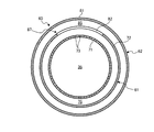
- FIG. 3 is a cross-sectional view of the damping device of the first embodiment when cut along the axial direction.
- 4 is a cross-sectional view taken along the line AA in FIG. 5 is a cross-sectional view taken along the line BB in FIG.
- FIG. 6 is a development view in which the acoustic liner of Example 1 is developed in the circumferential direction.
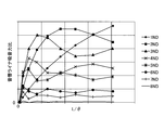
- FIG. 7 is a graph relating to the performance of the sound absorption force of the acoustic liner of the first embodiment.
- FIG. 8 is a development view in which the acoustic liner of Example 2 is developed in the circumferential direction.
- FIG. 1 is a schematic configuration diagram of a gas turbine according to the first embodiment.
- FIG. 2 is an enlarged view of the combustor of the gas turbine of FIG.
- FIG. 3 is a cross-sectional view of the damping device of the first embodiment when cut along the axial direction.
- 4 is a cross-sectional view taken along the line AA in FIG. 5 is a cross-sectional view taken along the line BB in FIG.
- FIG. 6 is a development view in which the acoustic liner of Example 1 is developed in the circumferential direction.
- FIG. 7 is a graph relating to the performance of the sound absorption force of the acoustic liner of the first embodiment.
- the gas turbine 1 includes a compressor 11, a combustor 12, a turbine 13, and an exhaust chamber 14, and a generator (not shown) is connected to the compressor 11 side.
- the compressor 11 has an air intake 15 for taking in air, and a plurality of stationary blades 17 and a plurality of moving blades 18 are alternately arranged in the compressor casing 16.
- the combustor 12 is combustible by supplying fuel to the compressed air compressed by the compressor 11 and igniting it with a burner.
- a plurality of stationary blades 21 and a plurality of moving blades 22 are alternately arranged in a turbine casing 20.
- the exhaust chamber 14 has an exhaust diffuser 23 that is continuous with the turbine 13.
- the rotor 24 is positioned so as to pass through the central portion of the compressor 11, the combustor 12, the turbine 13, and the exhaust chamber 14, and the end portion on the compressor 11 side is rotatably supported by the bearing portion 25.
- the end portion on the exhaust chamber 14 side is rotatably supported by the bearing portion 26.
- a plurality of disk plates are fixed to the rotor 24, the rotor blades 18 and 22 are connected, and a drive shaft of a generator (not shown) is connected to an end portion on the compressor 11 side.
- the air taken in from the air intake port 15 of the compressor 11 passes through the plurality of stationary blades 21 and the plurality of moving blades 22 and is compressed into high-temperature and high-pressure compressed air.
- the fuel is burned by supplying a predetermined fuel to the compressed air.
- the high-temperature and high-pressure combustion gas that is the working fluid generated by the combustor 12 passes through the plurality of stationary blades 21 and the plurality of moving blades 22 constituting the turbine 13 to drive and rotate the rotor 24. Then, the generator connected to the rotor 24 is driven.
- the exhaust gas that is the combustion gas after driving and rotating the rotor 24 is converted into a static pressure by the exhaust diffuser 23 in the exhaust chamber 14 and then released to the atmosphere.
- FIG. 2 is an enlarged view of the combustor of FIG.
- the combustor 12 has a combustor casing 30.
- the combustor casing 30 includes an inner cylinder 32 disposed inside the outer cylinder 31, and a tail cylinder 33 connected to the tip of the inner cylinder 32, and a center inclined with respect to the rotation axis I of the rotor 24. It extends along the axis S.
- the outer cylinder 31 is fastened to a casing housing 27 that forms a casing 34 into which compressed air from the compressor 11 flows.
- the base end of the inner cylinder 32 is supported by the outer cylinder 31, and is arranged inside the outer cylinder 31 at a predetermined interval from the outer cylinder 31.
- a pilot burner 40 is disposed along the central axis S at the center of the inner cylinder 32.
- a plurality of main burners 50 are arranged around the pilot burner 40 at equal intervals and in parallel with the pilot burner 40 so as to surround the pilot burner 40.
- the tail tube 33 has a base end formed in a cylindrical shape and is connected to the tip of the inner tube 32.
- the transition piece 33 is formed to have a small cross-sectional area and bend toward the tip side, and is open toward the first stage stationary blade 21 of the turbine 13.
- the transition piece 33 forms a combustion chamber 35 therein.
- the tail cylinder 33 is provided with a damping device 60 for attenuating combustion vibration generated in the tail cylinder 33.
- the attenuation device 60 includes an acoustic liner 61 provided on the inner peripheral side and an acoustic damper 62 provided on the outer peripheral side.
- the acoustic liner 61 is provided to absorb high-frequency vibration generated by combustion vibration
- the acoustic damper 62 is provided to absorb low-frequency vibration generated by combustion vibration.
- the acoustic liner 61 is provided over the entire circumference in the circumferential direction along the outer circumference of the cylindrical tail cylinder 33.
- the acoustic liner 61 includes a perforated plate 71 in which a plurality of sound absorbing holes 73 are formed, and a liner cover 72 provided around the perforated plate 71.
- the perforated plate 71 also serves as a part of the tail cylinder 33, is formed in a cylindrical shape, and the inside thereof is the combustion chamber (internal flow path) 35 described above.
- the liner cover 72 has a cylindrical cylindrical portion 72a provided on the outer peripheral side of the porous plate 71, and a pair of side plate portions 72b provided on both axial sides of the central axis S of the cylindrical portion 72a.
- an acoustic liner resonance space 75 is formed over the entire circumference between the perforated plate 71 and the liner cover 72, and the acoustic liner resonance space 75 is blocked from the external space by the liner cover 72.
- the acoustic damper 62 is provided over the entire circumference in the circumferential direction along the outer circumference of the acoustic liner 61.
- the acoustic damper 62 includes a damper cover 81 provided around the acoustic liner 61 and a damper opening 82 formed in the cylindrical portion 72 a of the liner cover 72.
- the damper cover 81 includes a cylindrical cylindrical portion 81a provided on the outer peripheral side of the acoustic liner 61, and a pair of side plate portions 81b provided on both axial sides of the central axis S of the cylindrical portion 81a. 61 is provided so as to cover the cylindrical portion 72a. Accordingly, an acoustic damper resonance space 85 is formed over the entire circumference between the cylindrical portion 72 a of the acoustic liner 61 and the damper cover 81, and the acoustic damper resonance space 85 is blocked from the external space by the damper cover 81.
- the damper cover 81 includes a cylindrical cylindrical portion 81a provided on the outer peripheral side of the acoustic liner 61, and a pair of side plate portions 81b provided on both axial sides of the central axis S of the cylindrical portion 81a. 61 is provided so as to cover the cylindrical portion 72a. Accordingly, an acoustic damper resonance space 85 is formed over the entire circumference
- the damper opening 82 is an opening that connects the acoustic liner resonance space 75 of the acoustic liner 61 and the acoustic damper resonance space 85 of the acoustic damper 62. As shown in FIG. 6, the damper opening 82 is formed close to one side in the width direction when the axial direction of the central axis S is the width direction with respect to the cylindrical portion 72 a of the liner cover 72 developed in the circumferential direction. It is a rectangular opening.
- the cylindrical portion 72a of the liner cover 72 includes a dividing portion 87 divided in the circumferential direction by the damper opening 82, and a continuous portion 88 continuous in the circumferential direction. Is formed. Therefore, the acoustic liner resonance space 75 is formed over the entire circumference in the continuous portion 88 as shown in FIG. 4, while being divided in the circumferential direction in the divided portion 87 as shown in FIG. 5. Formed.
- the continuous portion 88 is provided on one side in the width direction of the liner cover 72, and the dividing portion 87 is provided on the other side in the width direction of the liner cover 72.
- the combustion vibration when combustion vibration occurs due to combustion of fuel in the combustion chamber 35, the combustion vibration is generated from the acoustic chamber resonance via the sound absorption hole 73 of the perforated plate 71. This is transmitted to the space 75.
- the combustion vibrations transmitted in the acoustic liner resonance space 75 the combustion vibrations having a high frequency are attenuated in the acoustic liner resonance space 75.
- the acoustic liner resonance space 75 communicates with the acoustic damper resonance space 85 via the damper opening 82. For this reason, the combustion vibration generated in the combustion chamber 35 is transmitted to the acoustic damper resonance space 85 via the acoustic liner resonance space 75. Of the combustion vibrations transmitted to the acoustic damper resonance space 85, the combustion vibrations having a low frequency are attenuated in the acoustic damper resonance space 85.
- the attenuation performance (sound absorption force) by the acoustic liner 61 of Example 1 will be described.
- the vertical axis represents the conventional ratio of the sound absorption force of the acoustic liner 61
- the horizontal axis represents the aspect ratio (L / ⁇ ) of the damper opening 82.
- the sound absorption force of the acoustic liner 61 is derived by analysis using a predetermined calculation method.
- the damper opening 82 is formed over the entire width of the cylindrical portion 72 a of the liner cover 72.
- the opening area of the damper opening 82 of Example 1 and the conventional damper opening are the same area.
- the aspect ratio of the damper opening 82 is expressed by L / ⁇ , where L is the length in the width direction of the damper opening 82 and ⁇ is the length in the circumferential direction of the damper opening 82.
- the sound absorption force of the acoustic liner 61 is analyzed over a plurality of acoustic modes.
- the acoustic mode is represented by the number of nodal diamonds (ND), and the number of nodal diamonds indicates the number of sine waves generated in the circumferential direction of the combustion chamber 35. That is, 1ND is an acoustic mode in which only one sine wave is generated in the circumferential direction of the combustion chamber 35. Similarly, 2 to 8ND is only 2 to 8 sine waves in the circumferential direction of the combustion chamber 35.
- the acoustic mode to be generated.
- the sound absorption force of the acoustic liner 61 is analyzed over 360 ° while varying the sine wave generated along the circumferential direction of the combustion chamber 35 by a predetermined phase.
- the damper opening 82 can be formed while the acoustic liner 61 is provided with the continuous portion 88. For this reason, since the acoustic liner resonance space 75 and the acoustic damper resonance space 85 can be communicated with each other by the damper opening 82 at the divided portion 87 of the acoustic liner 61, the combustion vibration generated in the combustion chamber 35 is attenuated by the acoustic damper 62. Can be made.
- the acoustic liner resonance space 75 of the acoustic liner 61 is not divided in the circumferential direction by the continuous portion 88 of the acoustic liner 61, the acoustic liner resonance space 75 is moved in the circumferential direction at the continuous portion 88 of the acoustic liner 61. Can be formed. For this reason, the combustion vibration in the combustion chamber 35 can be suitably damped by the acoustic liner 61 as much as the acoustic liner resonance space 75 of the acoustic liner 61 is not divided. From the above, it is possible to improve the performance of vibration suppression by the acoustic liner 61 while maintaining the performance of vibration suppression by the acoustic damper 62.
- the damper opening 82 can be formed close to one side in the width direction of the acoustic liner 61.
- the dividing part 87 can be provided on one side in the width direction of the acoustic liner 61, and the continuous part 88 can be provided on the other side in the width direction of the acoustic liner 61.
- the damper opening 82 can be easily formed by machining by making the damper opening 82 rectangular.
- the combustion vibration generated by the combustion gas (fluid) flowing through the tail cylinder 33 of the combustor 12 can be suitably damped by the damping device 60. That is, by providing the acoustic liner 61 to which the acoustic damper 62 is connected along the outer periphery of the tail cylinder 33 of the combustor 12, the combustion vibration near the flame of the combustor 12 can be attenuated by the acoustic liner 61 and the acoustic damper 62. The combustion vibration can be attenuated more effectively.
- the combustor 12 that suppresses combustion vibration, it is possible to suppress a load due to combustion vibration, and thus it is possible to improve the durability of the gas turbine 1.
- the damper opening 82 is rectangular.
- the present invention is not limited to this shape, and may be any shape such as a circle or an ellipse.
- FIG. 8 is a development view in which the acoustic liner of Example 2 is developed in the circumferential direction.
- the damper opening 82 is formed close to one side in the width direction with respect to the cylindrical portion 72a of the liner cover 72.
- the damper opening 82 is provided. Is formed at the center in the width direction with respect to the cylindrical portion 72 a of the liner cover 72.
- the damper opening 82 is formed at the center in the width direction of the cylindrical portion 72 a of the liner cover 72, so the dividing portion 87 is formed at the center in the width direction. Is done. Further, a pair of continuous portions 88 are provided on both sides in the width direction with the divided portion 87 interposed therebetween.
- the damper opening 82 can be formed at the center in the width direction of the acoustic liner 61.
- the dividing part 87 can be provided in the center of the width direction of the acoustic liner 61, and a pair of continuous parts 88 can be provided on both sides of the width direction of the acoustic liner 61.
Landscapes
- Engineering & Computer Science (AREA)
- Mechanical Engineering (AREA)
- General Engineering & Computer Science (AREA)
- Chemical & Material Sciences (AREA)
- Combustion & Propulsion (AREA)
- Soundproofing, Sound Blocking, And Sound Damping (AREA)
- Exhaust Silencers (AREA)
Abstract
Description
11 圧縮機
12 燃焼器
13 タービン
24 ロータ
30 燃焼器ケーシング
31 外筒
32 内筒
33 尾筒
34 車室
35 燃焼室
60 減衰装置
61 音響ライナ
62 音響ダンパ
71 多孔板
72 ライナカバー
75 音響ライナ共鳴空間
81 ダンパカバー
82 ダンパ開口
85 音響ダンパ共鳴空間
87 分断部位
88 連続部位
Claims (6)
- 流体が流通する内部流路の外周に沿って音響ライナ共鳴空間を形成する音響ライナと、
前記音響ライナの外周側に設けられ、前記音響ライナ共鳴空間と連通する音響ダンパ共鳴空間を形成する音響ダンパと、を備え、
前記音響ライナは、
前記音響ライナ共鳴空間と前記音響ダンパ共鳴空間とを連通させるために前記音響ダンパが接続されるダンパ開口によって、前記内部流路の外周に沿う方向において分断される部位となる分断部位と、
前記内部流路の外周に沿う方向に亘って連続する部位となる連続部位と、を有することを特徴とする減衰装置。 - 前記音響ライナは、前記内部流路の外周に沿う方向が周方向となる円筒形状に形成されており、前記周方向に直交する軸方向が幅方向となっており、
前記ダンパ開口は、前記幅方向の一方側に寄せて形成されることを特徴とする請求項1に記載の減衰装置。 - 前記音響ライナは、前記内部流路の外周に沿う方向が周方向となる円筒形状に形成されており、前記周方向に直交する軸方向が幅方向となっており、
前記ダンパ開口は、前記幅方向の中央に形成されることを特徴とする請求項1に記載の減衰装置。 - 前記ダンパ開口は、矩形状の開口に形成されることを特徴とする請求項1から3のいずれか1項に記載の減衰装置。
- 請求項1から4のいずれか1項に記載の減衰装置と、
内部に前記内部流路を形成する尾筒と、を備えることを特徴とする燃焼器。 - 請求項5に記載の燃焼器と、
前記燃焼器において発生する燃焼ガスにより回転するタービンと、を備えることを特徴とするガスタービン。
Priority Applications (5)
| Application Number | Priority Date | Filing Date | Title |
|---|---|---|---|
| CN201580075590.7A CN107250491B (zh) | 2015-02-23 | 2015-02-23 | 衰减装置、燃烧器以及燃气轮机 |
| PCT/JP2015/055073 WO2016135833A1 (ja) | 2015-02-23 | 2015-02-23 | 減衰装置、燃焼器及びガスタービン |
| KR1020177023026A KR20170103011A (ko) | 2015-02-23 | 2015-02-23 | 감쇠 장치, 연소기 및 가스 터빈 |
| DE112015006211.4T DE112015006211B4 (de) | 2015-02-23 | 2015-02-23 | Dämpfungsvorrichtung, brennkammer und gasturbine |
| US15/551,769 US10844792B2 (en) | 2015-02-23 | 2015-02-23 | Damping device, combustor, and gas turbine |
Applications Claiming Priority (1)
| Application Number | Priority Date | Filing Date | Title |
|---|---|---|---|
| PCT/JP2015/055073 WO2016135833A1 (ja) | 2015-02-23 | 2015-02-23 | 減衰装置、燃焼器及びガスタービン |
Publications (1)
| Publication Number | Publication Date |
|---|---|
| WO2016135833A1 true WO2016135833A1 (ja) | 2016-09-01 |
Family
ID=56788011
Family Applications (1)
| Application Number | Title | Priority Date | Filing Date |
|---|---|---|---|
| PCT/JP2015/055073 Ceased WO2016135833A1 (ja) | 2015-02-23 | 2015-02-23 | 減衰装置、燃焼器及びガスタービン |
Country Status (5)
| Country | Link |
|---|---|
| US (1) | US10844792B2 (ja) |
| KR (1) | KR20170103011A (ja) |
| CN (1) | CN107250491B (ja) |
| DE (1) | DE112015006211B4 (ja) |
| WO (1) | WO2016135833A1 (ja) |
Families Citing this family (11)
| Publication number | Priority date | Publication date | Assignee | Title |
|---|---|---|---|---|
| US10670271B2 (en) * | 2016-09-30 | 2020-06-02 | DOOSAN Heavy Industries Construction Co., LTD | Acoustic dampening liner cap and gas turbine combustor including the same |
| JP6543756B1 (ja) * | 2018-11-09 | 2019-07-10 | 三菱日立パワーシステムズ株式会社 | 燃焼器部品、燃焼器、ガスタービン及び燃焼器部品の製造方法 |
| US10753226B1 (en) * | 2019-05-07 | 2020-08-25 | United States Of America As Represented By The Administrator Of Nasa | Reverse vortex ring (RVR) for dramatic improvements in rocket engine turbomachinery rotordynamic stability margins |
| JP7289752B2 (ja) * | 2019-08-01 | 2023-06-12 | 三菱重工業株式会社 | 音響減衰器、筒アッセンブリ、燃焼器、ガスタービン及び筒アッセンブリの製造方法 |
| CN114502883B (zh) * | 2019-12-24 | 2023-08-11 | 三菱重工业株式会社 | 燃烧器部件、具备该燃烧器部件的燃烧器及具备该燃烧器的燃气轮机 |
| US11796358B2 (en) | 2020-09-10 | 2023-10-24 | Virginia Tech Intellectual Properties, Inc. | Flow measurement for a gas turbine engine |
| GB202014210D0 (en) | 2020-09-10 | 2020-10-28 | Rolls Royce Plc | Gas turbine engine with airflow measurement system |
| US11747236B2 (en) * | 2020-09-10 | 2023-09-05 | Virginia Tech Intellectual Properties, Inc. | Flow measurement for a gas turbine engine |
| US11821771B2 (en) * | 2020-09-10 | 2023-11-21 | Virginia Tech Intellectual Properties, Inc. | Flow measurement for a gas turbine engine |
| EP3974723B1 (en) * | 2020-09-23 | 2023-08-30 | Ansaldo Energia Switzerland AG | Gas turbine for power plant comprising a damping device |
| JP6980144B1 (ja) * | 2021-03-24 | 2021-12-15 | 三菱パワー株式会社 | ガスタービン用燃焼器、ガスタービン及びガスタービンの組立方法 |
Citations (4)
| Publication number | Priority date | Publication date | Assignee | Title |
|---|---|---|---|---|
| JP2006266671A (ja) * | 2005-02-22 | 2006-10-05 | Mitsubishi Heavy Ind Ltd | 減衰装置、燃焼器及びガスタービン |
| WO2010097982A1 (ja) * | 2009-02-27 | 2010-09-02 | 三菱重工業株式会社 | 燃焼器およびこれを備えたガスタービン |
| JP2014206350A (ja) * | 2013-04-16 | 2014-10-30 | 三菱重工業株式会社 | 音響ダンパ装置 |
| JP2014238099A (ja) * | 2011-03-22 | 2014-12-18 | 三菱重工業株式会社 | 燃焼器およびガスタービン |
Family Cites Families (12)
| Publication number | Priority date | Publication date | Assignee | Title |
|---|---|---|---|---|
| US6351947B1 (en) * | 2000-04-04 | 2002-03-05 | Abb Alstom Power (Schweiz) | Combustion chamber for a gas turbine |
| US6530221B1 (en) * | 2000-09-21 | 2003-03-11 | Siemens Westinghouse Power Corporation | Modular resonators for suppressing combustion instabilities in gas turbine power plants |
| JP2002317650A (ja) * | 2001-04-24 | 2002-10-31 | Mitsubishi Heavy Ind Ltd | ガスタービン燃焼器 |
| GB2390150A (en) * | 2002-06-26 | 2003-12-31 | Alstom | Reheat combustion system for a gas turbine including an accoustic screen |
| WO2004051063A1 (ja) * | 2002-12-02 | 2004-06-17 | Mitsubishi Heavy Industries, Ltd. | ガスタービン燃焼器、及びこれを備えたガスタービン |
| US7080514B2 (en) * | 2003-08-15 | 2006-07-25 | Siemens Power Generation,Inc. | High frequency dynamics resonator assembly |
| US7413053B2 (en) * | 2006-01-25 | 2008-08-19 | Siemens Power Generation, Inc. | Acoustic resonator with impingement cooling tubes |
| JP5010517B2 (ja) | 2008-03-26 | 2012-08-29 | 三菱重工業株式会社 | ガスタービン |
| EP2385303A1 (en) * | 2010-05-03 | 2011-11-09 | Alstom Technology Ltd | Combustion Device for a Gas Turbine |
| DE102011081962A1 (de) * | 2011-09-01 | 2013-03-07 | Siemens Aktiengesellschaft | Brennkammer für eine Gasturbinenanlage |
| US9395082B2 (en) * | 2011-09-23 | 2016-07-19 | Siemens Aktiengesellschaft | Combustor resonator section with an internal thermal barrier coating and method of fabricating the same |
| US9410484B2 (en) * | 2013-07-19 | 2016-08-09 | Siemens Aktiengesellschaft | Cooling chamber for upstream weld of damping resonator on turbine component |
-
2015
- 2015-02-23 WO PCT/JP2015/055073 patent/WO2016135833A1/ja not_active Ceased
- 2015-02-23 KR KR1020177023026A patent/KR20170103011A/ko not_active Ceased
- 2015-02-23 DE DE112015006211.4T patent/DE112015006211B4/de active Active
- 2015-02-23 US US15/551,769 patent/US10844792B2/en active Active
- 2015-02-23 CN CN201580075590.7A patent/CN107250491B/zh active Active
Patent Citations (4)
| Publication number | Priority date | Publication date | Assignee | Title |
|---|---|---|---|---|
| JP2006266671A (ja) * | 2005-02-22 | 2006-10-05 | Mitsubishi Heavy Ind Ltd | 減衰装置、燃焼器及びガスタービン |
| WO2010097982A1 (ja) * | 2009-02-27 | 2010-09-02 | 三菱重工業株式会社 | 燃焼器およびこれを備えたガスタービン |
| JP2014238099A (ja) * | 2011-03-22 | 2014-12-18 | 三菱重工業株式会社 | 燃焼器およびガスタービン |
| JP2014206350A (ja) * | 2013-04-16 | 2014-10-30 | 三菱重工業株式会社 | 音響ダンパ装置 |
Also Published As
| Publication number | Publication date |
|---|---|
| CN107250491B (zh) | 2019-08-16 |
| US10844792B2 (en) | 2020-11-24 |
| KR20170103011A (ko) | 2017-09-12 |
| DE112015006211T5 (de) | 2017-11-02 |
| US20180038282A1 (en) | 2018-02-08 |
| DE112015006211B4 (de) | 2022-10-06 |
| CN107250491A (zh) | 2017-10-13 |
Similar Documents
| Publication | Publication Date | Title |
|---|---|---|
| CN107250491B (zh) | 衰减装置、燃烧器以及燃气轮机 | |
| JP5995932B2 (ja) | 燃焼器およびガスタービン | |
| CN102165263B (zh) | 燃烧器及具备该燃烧器的燃气轮机 | |
| JP5709401B2 (ja) | 一体の共振器を持つ噴射器 | |
| CN102753807B (zh) | 用于从燃气涡轮发动机喷射气体的装置及燃气涡轮发动机 | |
| JP4754987B2 (ja) | 減衰装置、燃焼器及びガスタービン | |
| JP6258042B2 (ja) | 減衰装置、燃焼器及びガスタービン | |
| JP2017082770A (ja) | 回転機械用のノイズバッフル及びそれを作成する方法 | |
| CN114026365B (zh) | 声音衰减器、筒组件、燃烧器、燃气轮机及筒组件的制造方法 | |
| TWI557375B (zh) | Vibration dampers, burners and gas turbines | |
| JP6640581B2 (ja) | 音響ダンパ、燃焼器およびガスタービン | |
| JP6097186B2 (ja) | 過給機用サイレンサ | |
| EP3692264B1 (en) | An air silencer connectable to a compressor part of a turbocharger | |
| JP6980144B1 (ja) | ガスタービン用燃焼器、ガスタービン及びガスタービンの組立方法 | |
| JP7257157B2 (ja) | 音響ダンパ、燃焼器およびガスタービン | |
| JP6253199B2 (ja) | ダクト及びこれを備えたガスタービン | |
| RU2269677C1 (ru) | Силовая стойка корпуса компрессора турбореактивного двигателя |
Legal Events
| Date | Code | Title | Description |
|---|---|---|---|
| 121 | Ep: the epo has been informed by wipo that ep was designated in this application |
Ref document number: 15883131 Country of ref document: EP Kind code of ref document: A1 |
|
| WWE | Wipo information: entry into national phase |
Ref document number: 15551769 Country of ref document: US |
|
| ENP | Entry into the national phase |
Ref document number: 20177023026 Country of ref document: KR Kind code of ref document: A |
|
| WWE | Wipo information: entry into national phase |
Ref document number: 112015006211 Country of ref document: DE |
|
| 122 | Ep: pct application non-entry in european phase |
Ref document number: 15883131 Country of ref document: EP Kind code of ref document: A1 |
|
| NENP | Non-entry into the national phase |
Ref country code: JP |