WO2016132695A1 - 非接触電力伝送システム - Google Patents
非接触電力伝送システム Download PDFInfo
- Publication number
- WO2016132695A1 WO2016132695A1 PCT/JP2016/000556 JP2016000556W WO2016132695A1 WO 2016132695 A1 WO2016132695 A1 WO 2016132695A1 JP 2016000556 W JP2016000556 W JP 2016000556W WO 2016132695 A1 WO2016132695 A1 WO 2016132695A1
- Authority
- WO
- WIPO (PCT)
- Prior art keywords
- power
- temperature
- pad
- fan
- power transmission
- Prior art date
- Legal status (The legal status is an assumption and is not a legal conclusion. Google has not performed a legal analysis and makes no representation as to the accuracy of the status listed.)
- Ceased
Links
Images










Classifications
-
- B—PERFORMING OPERATIONS; TRANSPORTING
- B60—VEHICLES IN GENERAL
- B60L—PROPULSION OF ELECTRICALLY-PROPELLED VEHICLES; SUPPLYING ELECTRIC POWER FOR AUXILIARY EQUIPMENT OF ELECTRICALLY-PROPELLED VEHICLES; ELECTRODYNAMIC BRAKE SYSTEMS FOR VEHICLES IN GENERAL; MAGNETIC SUSPENSION OR LEVITATION FOR VEHICLES; MONITORING OPERATING VARIABLES OF ELECTRICALLY-PROPELLED VEHICLES; ELECTRIC SAFETY DEVICES FOR ELECTRICALLY-PROPELLED VEHICLES
- B60L50/00—Electric propulsion with power supplied within the vehicle
- B60L50/50—Electric propulsion with power supplied within the vehicle using propulsion power supplied by batteries or fuel cells
- B60L50/60—Electric propulsion with power supplied within the vehicle using propulsion power supplied by batteries or fuel cells using power supplied by batteries
-
- B—PERFORMING OPERATIONS; TRANSPORTING
- B60—VEHICLES IN GENERAL
- B60H—ARRANGEMENTS OF HEATING, COOLING, VENTILATING OR OTHER AIR-TREATING DEVICES SPECIALLY ADAPTED FOR PASSENGER OR GOODS SPACES OF VEHICLES
- B60H1/00—Heating, cooling or ventilating devices
- B60H1/24—Ventilating devices where the heating or cooling is irrelevant
-
- H—ELECTRICITY
- H02—GENERATION; CONVERSION OR DISTRIBUTION OF ELECTRIC POWER
- H02J—ELECTRIC POWER NETWORKS; CIRCUIT ARRANGEMENTS OR SYSTEMS FOR SUPPLYING OR DISTRIBUTING ELECTRIC POWER; SYSTEMS FOR STORING ELECTRIC ENERGY
- H02J7/00—Circuit arrangements for charging or discharging batteries or for supplying loads from batteries
-
- Y—GENERAL TAGGING OF NEW TECHNOLOGICAL DEVELOPMENTS; GENERAL TAGGING OF CROSS-SECTIONAL TECHNOLOGIES SPANNING OVER SEVERAL SECTIONS OF THE IPC; TECHNICAL SUBJECTS COVERED BY FORMER USPC CROSS-REFERENCE ART COLLECTIONS [XRACs] AND DIGESTS
- Y02—TECHNOLOGIES OR APPLICATIONS FOR MITIGATION OR ADAPTATION AGAINST CLIMATE CHANGE
- Y02T—CLIMATE CHANGE MITIGATION TECHNOLOGIES RELATED TO TRANSPORTATION
- Y02T10/00—Road transport of goods or passengers
- Y02T10/60—Other road transportation technologies with climate change mitigation effect
- Y02T10/70—Energy storage systems for electromobility, e.g. batteries
Definitions
- This disclosure relates to a non-contact power transmission system having a power transmission device and a power reception device.
- the vehicle-mounted power receiving device includes a bidirectional fan that can switch between blowing and exhausting by switching the rotation direction between forward rotation and reverse rotation, and a bidirectional fan according to the temperature of the power storage device and the passenger compartment. And a control unit for controlling the rotation direction.
- This disclosure is intended to provide a non-contact power transmission system that can cool the pad reliably when performing charging (power transmission) at a lower cost than before.
- the non-contact power transmission system includes a power transmission pad provided in a vehicle passage, and a power transmission control unit that controls power to be output to the power transmission pad and transmitted
- the power receiving device includes a power receiving pad provided in the vehicle and a power receiving control unit that controls electric power received by the power receiving pad.
- a power transmission pad and a power reception pad face each other (oppose) and perform power transmission in a non-contact manner.
- the power reception control unit performs control to drive a fan provided in the vehicle when performing power transmission and to cool one or both of the power transmission pad and the power reception pad with wind generated by driving the fan.
- a duct that adjusts the wind direction so that the wind generated by driving the fan is directed to one or both of the power transmission pad and the power reception pad.
- the pad can be cooled more reliably.
- the power reception control unit drives the fan when the temperature specified by the temperature specifying unit exceeds the first temperature threshold (TH), and is lower than the first temperature threshold. When the temperature falls below the temperature threshold (TL), control is performed to stop the fan.
- TH first temperature threshold
- TL temperature threshold
- the fan is driven when the first temperature threshold is exceeded, and the fan is stopped when the temperature falls below the second temperature threshold, so that the fan can be intermittently operated. Therefore, the electric power required for driving the fan can be kept lower than in continuous operation.
- the power reception control unit performs control so as not to send wind from the fan to one or both of the power reception pad and the power transmission pad until a predetermined condition is satisfied.
- connecting means electrically connecting.
- Each figure illustrates elements necessary to describe the present disclosure, and not all actual elements are illustrated. When referring to directions such as up, down, left and right, the description in the drawings is used as a reference.
- Alphanumeric continuous codes are abbreviated using the symbol “ ⁇ ”.
- the alphabetic character of the sign means different elements in upper case and lower case.
- the power reception control unit 15A and the charging ECU 15a illustrated in FIG. 6 are separate elements.
- an electromagnetic induction method in which power is transmitted by coupling a magnetic flux generated from an alternating current to a winding.
- charging and power transmission are synonymous unless otherwise specified.
- the non-contact power transmission system 100 includes a power receiving device 13 and a power transmitting device 20.
- the vehicle 10 shown in FIG. 1 corresponds to a hybrid vehicle (Hybrid Vehicle), an electric vehicle (Electric Vehicle), or the like that requires electric power for part or all of traveling.
- the vehicle 10 includes a radiator fan 11a, a condenser fan 11d, a control system 12, a power receiving device 13, a battery 14, and the like.
- Both the radiator fan 11a and the condenser fan 11d correspond to “fan F” and are provided in the compartment 11b on the front side of the cabin 11c of the vehicle 10. In the compartment 11b, you may provide the temperature sensor 18 which detects the temperature in the said compartment 11b (refer FIG. 3).
- the radiator fan 11a is used when a radiator (not shown) provided in the vehicle 10 is cooled.
- the condenser fan 11d is used when cooling an air conditioning condenser (not shown) provided in the vehicle 10.
- the control system 12 is a system that controls the entire vehicle 10, and includes, for example, an ECU (Electronic Control Unit) and a computer.
- the power receiving device 13 is a power receiving side element that performs power transmission without contact with the power transmitting device 20 described later, and includes a power receiving control unit 15, a power receiving pad 16, and the like.
- the power reception control unit 15 performs control such as storing power in the battery 14 and communicating with the control system 12 for the power received by the power receiving pad 16. A configuration example of the power reception control unit 15 will be described later (see FIG. 6).
- the power receiving pad 16 includes elements (windings, capacitors, and the like) that perform power transmission without contact.
- the battery 14 may be of any type as long as it can store and discharge, and for example, a secondary battery such as a lithium ion battery or a lead storage battery.
- the battery 14 may include a battery ECU that outputs a signal such as a charge request based on the charge pressure.
- the power transmission device 20 is a power transmission-side element that performs power transmission without contact with the power reception device 13 described above, and includes a power transmission pad 21, a power transmission control unit 22, and the like.
- the power transmission pad 21 is provided in a passage (see FIG. 1, P) of the vehicle 10 and includes elements (windings, capacitors, etc.) that perform power transmission without contact.
- the power transmission control unit 22 outputs power supplied from the power source 30 to the power transmission pad 21 to perform power transmission control of power transmission. A configuration example of the power transmission control unit 22 will be described later (see FIG. 5).
- Both the power receiving pad 16 and the power transmitting pad 21 correspond to “power transmitting pads”.
- the power receiving pad 16 and the power transmitting pad 21 may have the same configuration or different configurations except that the winding and the capacitor are set to resonate at a predetermined frequency.
- the wind thus generated cools one or both of the power receiving pad 16 and the power transmitting pad 21. Note that there may be wind that does not contribute to cooling of the power receiving pad 16 or the power transmitting pad 21 even when the fan F is driven.
- the power transmission control unit 22 shown in FIG. 5 includes a charging ECU 22a, a control circuit 22b, a communication device 22c, a power transmission circuit 22d, a current sensor 22e, and the like. One or more of these elements may be provided outside the power transmission control unit 22.
- the charging ECU 22a is an ECU on the ground side and performs necessary control relating to charging of the battery 14. For example, it includes control for transmitting a charging request output from the battery 14 (particularly, the battery ECU) and transmitted via the communication device 22c or the communication device 15c to the control circuit 22b.
- the control circuit 22b is provided with a temperature estimation unit 22b1 as necessary, and controls the power transmission device 20 as a whole.
- the control circuit 22b is configured to transmit power and fan based on the temperature T1 of the power transmission pad 21 detected by the temperature sensor 23, the current I1 flowing through the power transmission pad 21 (specifically, a coil) detected by the current sensor 22e, and the like. Control such as driving of F is performed. Further, based on the charging request transmitted from the charging ECU 22 a, the power transmission from the power transmission pad 21 is controlled by receiving power supplied from the power source 30 for charging the battery 14. Both the temperature sensor 23 and the temperature estimation unit 22b1 correspond to the temperature specifying unit TS.
- the temperature estimation unit 22b1 estimates the temperature T1 of the power transmission pad 21 (specifically, a coil) based on the current I1 detected by the current sensor 22e.
- the estimation form of temperature T1 is not ask
- the correlation between the current I1 and the temperature T1 may be recorded in a table, a map, or the like, or defined by a function formula.
- the communication device 22c performs communication with the communication device 15c provided in the power reception control unit 15A described later.
- the power transmission circuit 22 d includes a converter and an inverter, receives power supplied from the power source 30, and controls power transmission by the power transmission pad 21.
- a power reception control unit 15A shown in FIG. 6 is an example of the power reception control unit 15, and includes a charging ECU 15a, a control circuit 15b, a communication device 15c, a power reception circuit 15d, a current sensor 15e, and the like. One or more of these elements may be provided outside the power reception control unit 15A.
- the charging ECU 15a is an ECU on the vehicle 10 side, and performs necessary control regarding charging of the battery 14. For example, communication control is performed between the control system 12 and the control circuit 15b. Further, one or more fans F among the radiator fan 11a, the condenser fan 11d, and the rear fan 11e are driven and controlled. In addition, the charging request output from the battery 14 (particularly the battery ECU) and transmitted is transmitted to the control circuit 15b, or transmitted to the control circuit 22b via the communication device 22c or the communication device 15c.
- the control circuit 15b includes a temperature estimation unit 15b1 as necessary, and controls the entire power receiving device 13.
- the control circuit 15b includes the temperature T2 of the power receiving pad 16 detected by the temperature sensor 17, the temperature T3 in the compartment 11b detected by the temperature sensor 18, and the power receiving pad 16 detected by the current sensor 22e (specifically, Control such as power reception and driving of the fan F is performed based on the current I2 flowing through the coil).
- the temperature sensors 17 and 18 and the temperature estimation unit 15b1 all correspond to the temperature specifying unit TS.
- the temperature estimation unit 15b1 estimates temperatures T such as temperatures T2 and T3.
- the estimation form of temperature T2, T3 is not ask
- the temperature T2 of the power transmission pad 21 (specifically, the coil) is estimated based on the current I2 detected by the current sensor 15e.
- the temperature T3 is estimated based on the power consumption of the air conditioner (air conditioner, heater, etc.) included in the control information CI.
- the correlation between the current I2 and the temperature T2 and the correlation between the power consumption and the temperature T3 may be recorded in a table, a map, or the like, or defined by a functional expression.
- the communication device 15c performs communication between the communication devices 22c described above.
- the power receiving circuit 15d includes a converter, and performs control to store the power generated in the power receiving pad 16 in the battery 14.
- the current temperature T is specified [S12].
- the temperature T may be detected and specified by a temperature sensor, or may be estimated and specified by the temperature estimation units 15b1 and 22b1.
- the temperatures T2 and T1 detected by the temperature sensors 17 and 23, the temperature T3 detected by the temperature sensor 18, and the like are applicable.
- Examples of the temperature estimation units 15b1 and 22b1 are consumptions of temperatures T2 and T1 estimated based on currents I2 and I1 detected by the current sensors 15e and 22e, and air conditioning equipment (air conditioners, heaters, and the like) included in the control information CI.
- a temperature T3 estimated based on electric power corresponds to this.
- one or more temperatures T are specified from the detected or estimated temperatures T1 to T3.
- the cooling condition may be arbitrarily set as long as it is a condition for cooling the power transmission pad 21 and the power receiving pad 16 by driving the fan F. For example, whether or not the temperatures T2 and T1 exceed the temperature threshold Tth, whether or not the temperatures T3 and T4 are equal to or lower than a predetermined temperature Tx, and the like are applicable. Arbitrary values may be set for the temperature threshold Tth and the predetermined temperature Tx, respectively.
- the former temperature threshold value Tth may include a temperature threshold value Tth1 of the power transmission pad 21 and a temperature threshold value Tth2 of the power reception pad 16 shown in FIG.
- the fan F is driven (including re-driving; normal rotation) to send wind to the pads (the power receiving pad 16 and the power transmitting pad 21) [S17].
- control is performed so as not to send wind from the fan F to the pad until a predetermined condition is satisfied based on information about the vehicle 10 transmitted from the control system 12 (for example, traveling speed, temperature, etc.). May be.
- the predetermined condition may be set arbitrarily.
- the predetermined temperature Tx For example, the case where the temperature T3 of the compartment 11b is equal to or lower than the predetermined temperature Tx, the predetermined time has elapsed from the time of stopping, and the like. If the predetermined condition is satisfied, the fan F is driven to send air to the pad for cooling.
- the cooling capacity may be changed according to the temperature T [S19]. Specifically, one or more fans F are selected from the radiator fan 11a, the condenser fan 11d, and the rear fan 11e. Further, the rotational speed of the selected fan F is changed.
- An example of the relationship between the temperature T and the rotational speed N is shown by a characteristic line L1 in FIG.
- the rotational speed N is increased as the temperature T becomes higher than the temperature threshold Tth.
- the cooling efficiency ⁇ also changes.
- An example of the relationship between the rotational speed N and the cooling efficiency ⁇ is shown by a characteristic line L2 in FIG. In short, the control is performed so that the total amount of air generated by driving each fan increases as the temperature T increases.
- the charging process (power transmission process) shown in FIG. 10 is executed instead of the charging process shown in FIG. FIG. 10 differs from FIG. 7 in that S20 and S21 are executed instead of S16.
- the fan F is driven [S17], and the cooling capacity is changed according to the temperature T [S19].
- the temperature T is lower than the second temperature threshold TL (T ⁇ TL; NO in S20, YES in S21), the fan F is stopped [S18].
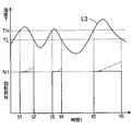
- the drive of the fan F according to the temperature T is as shown in FIG. A characteristic line L3 shown in FIG. Since the temperature T exceeds the first temperature threshold TH at times t1, t3, and t5 (YES in S20), the fan F is driven at the rotational speed N1 (S17, S19). At times t2, t4, and t6, the temperature T becomes equal to or lower than the second temperature threshold TL (NO in S20 and S21), so the fan F is stopped (S18). Therefore, intermittent operation of the fan F can be performed.
- the rotational speed N of the fan F is fixed at the rotational speed N1, but the rotational speed N may be increased as indicated by a two-dot chain line.
- the cooling capacity is increased.
- Embodiment 3 The third embodiment will be described with reference to FIGS.
- the same elements as those used in the first and second embodiments are denoted by the same reference numerals and description thereof is omitted. Therefore, differences from Embodiments 1 and 2 will be mainly described.
- the charging process (power transmission process) shown in FIG. 12 is executed instead of the charging process shown in FIG. FIG. 12 differs from FIG. 7 in that S30, S31, and S32 are executed instead of S12 to S16 and S19.
- the cooling capacity may be changed according to the current I [S32].
- S32 may be performed in the same manner as S19 except that the temperature T changes to the current I.
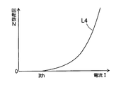
- An example of the relationship between the current I and the rotational speed N is shown by a characteristic line L4 in FIG. The rotational speed N is increased as the current I becomes larger than the current threshold Ith.
- the charging process shown in FIG. 10 may be applied by replacing the correlated temperature T with the current I. That is, the fan F is driven when the current I exceeds the first current threshold, and the fan F is stopped when the current I becomes equal to or less than the second current threshold.
- the first current threshold corresponds to the first temperature threshold TH
- the second current threshold corresponds to the second temperature threshold TL. Even with this configuration, the fan F can be intermittently operated as shown in FIG.
- Embodiment 4 will be described with reference to FIG. For simplicity of illustration and description, unless otherwise specified, the same elements as those used in Embodiments 1 to 3 are denoted by the same reference numerals and description thereof is omitted. Therefore, differences from Embodiments 1 to 3 will be mainly described.
- the vehicle 10 shown in FIG. 14 further includes ducts 11f and 11g as compared with the vehicle 10 shown in FIGS.
- the duct 11 f adjusts the wind direction so that the wind generated by driving the radiator fan 11 a and the condenser fan 11 d is directed to the power receiving pad 16. By this adjustment, wind flows as indicated by an arrow D6 indicated by a broken line in FIG. 14, and the power receiving pad 16 is cooled.
- the ducts 11f and 11g may be newly attached to the vehicle 10, or a structural portion (for example, a frame portion) of the vehicle 10 may be used.
- the duct 11g adjusts the wind direction so that the wind generated by driving the radiator fan 11a and the condenser fan 11d is directed to the power transmission pad 21. By this adjustment, wind flows as indicated by an arrow D7 indicated by a broken line in FIG. 14, and the power transmission pad 21 is cooled.
- the power receiving pad 16 and the power transmitting pad 21 can be cooled more reliably.
- Embodiment 5 will be described with reference to FIGS. For simplicity of illustration and description, unless otherwise specified, the same elements as those used in Embodiments 1 to 4 are denoted by the same reference numerals and description thereof is omitted. Therefore, differences from Embodiments 1 to 4 will be mainly described.
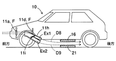
- the vehicle 10 shown in FIG. 15 is further provided with a duct 11h as compared with the vehicle 10 shown in FIGS.
- the duct 11h includes a throttle 11i, a power reception side wind direction port Ex1, a power transmission side wind direction port Ex2, and the like.
- the duct 11h may be newly provided in the vehicle 10, or a structural part (for example, a frame part) of the vehicle 10 may be used for a part or all of the duct 11h.
- the throttle 11i corresponds to a “flow rate adjusting unit”, and is configured such that the attitude (angle) can be controlled by the control system 12 or the charging ECU 15a (see FIG. 16 described later).
- the throttle 11i adjusts the flow rate (air volume) sent separately to the power reception side wind direction port Ex1 and the power transmission side wind direction port Ex2 according to the posture.
- the power receiving side wind direction port Ex1 corresponds to the duct 11f shown in FIG. 14, and adjusts the direction of the wind so that the wind generated by driving the radiator fan 11a is directed to the power receiving pad 16.
- the power transmission side wind direction port Ex2 corresponds to the duct 11g shown in FIG. 14 and adjusts the wind direction so that the wind generated by driving the radiator fan 11a is directed to the power transmission pad 21.
- the duct 11h shown in FIG. 15 shows an example of adjusting the wind generated by driving the radiator fan 11a. Although not shown, it may be configured to adjust the wind generated by driving the condenser fan 11d, or may be configured to adjust the wind generated by both driving.
- the power reception control unit 15B illustrated in FIG. 16 is an example of the power reception control unit 15, and is a configuration example that replaces the power reception control unit 15A illustrated in FIG.
- the power reception control unit 15B has the same configuration as the power reception control unit 15A, but the roles of the charging ECU 15a and the control circuit 15b are different.
- the charging ECU 15a in this configuration example controls the driving of the fan F and the attitude of the throttle 11i based on a signal transmitted from the control circuit 15b.
- the control circuit 15b controls the driving of the fan F and the attitude of the throttle 11i via the control system 12. That is, one or both of the charging ECU 15a and the control circuit 15b performs the attitude control of the throttle 11i.
- the air volume Q ⁇ b> 1 is a flow rate of wind blown from the power receiving side wind direction port Ex ⁇ b> 1 toward the power transmission pad 21.
- the air volume Q2 is the flow rate of the wind blown out from the power transmission side wind direction port Ex2 toward the power receiving pad 16.
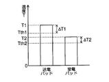
- FIG. 17 shows a temperature T2 and a temperature threshold Tth2 applied to the power receiving pad 16, and a temperature T1 and a temperature threshold Tth1 applied to the power transmitting pad 21.
- the charging process (power transmission process) shown in FIG. 18 is executed instead of the charging process shown in FIG. FIG. 10 differs from FIG. 7 in that S20 and S21 are executed instead of S16.
- the temperature T (T2, T1) specified in S12 satisfies the cooling condition [S16]. Specifically, when the temperature T2 exceeds the temperature threshold Tth2 (T2> Tth2) or when the temperature T1 exceeds the temperature threshold Tth1 (T1> Tth1), the temperature T exceeds the temperature threshold Tth (that is, the cooling condition is satisfied). Is satisfied).
- the fan F is driven [S17], and the cooling capacity is changed according to the temperature difference ⁇ T2, ⁇ T1 as shown by the two-dot chain line [S19].
- S19 in FIG. 17 may be executed as necessary, and is executed based on temperature differences ⁇ T2 and ⁇ T1 instead of the temperature T shown in S19 in FIG.
- the fan F is stopped [S18].
- Adjustment of air volume Q1, Q2 is executed after S17 (or S19).
- temperature differences ⁇ T1 and ⁇ T2 are obtained [S50], and it is determined whether or not the temperature difference ⁇ T1 exceeds the temperature difference ⁇ T2 [ ⁇ T1> ⁇ T2; S51]. If the temperature difference ⁇ T1 exceeds the temperature difference ⁇ T2 (YES), the attitude of the throttle 11i is adjusted so that the air volume Q1 is larger than the air volume Q2 [Q1> Q2; S52]. By this adjustment, the power transmission pad 21 can be preferentially cooled.
- the attitude of the throttle 11i is adjusted so that the air volume Q2 is larger than the air volume Q1 [Q2> Q1; S53].
- the power receiving pad 16 can be preferentially cooled.
- the charging process shown in FIG. 18 may be applied by replacing the correlated temperature T with the current I. That is, the fan F is driven when the current I exceeds the first current threshold, and the fan F is stopped when the current I becomes equal to or less than the second current threshold.
- the first current threshold corresponds to the first temperature threshold TH
- the second current threshold corresponds to the second temperature threshold TL. Even with this configuration, the fan F can be intermittently operated as shown in FIG.
- the radiator fan 11a and the condenser fan 11d provided in the compartment 11b are applied as the fan F (see FIGS. 1 to 4, 14, and 15).
- other fans F included in the compartment 11b may be used except for the radiator fan 11a and the condenser fan 11d, and other fans F may be used in combination. Since only the type of the fan F is different, the same effect as in the first to fifth embodiments can be obtained.
- the wind generated by driving the fan F is applied to the power receiving pad 16 and the power transmitting pad 21 for cooling (see FIGS. 1 to 4, 14, and 15).
- the power receiving pad 16 and the power transmitting pad 21 may be wetted and cooled by water (rain water, water generated during air conditioning, etc.).
- the vehicle 10 includes a storage member 11 j and a water supply member 11 k.
- the storage member 11j is a member that stores water.
- the water supply member 11k is a member that discharges water stored in the storage member 11j and wets the power receiving pad 16 or the power transmission pad 21.
- the water supply member 11k is provided as necessary, and corresponds to, for example, a pipe, a water discharge member, a sprayer, or the like.
- the amount of water discharged or sprayed from the water supply member 11k may be controlled according to the temperature T or current I.
- the power receiving pad 16 and the power transmitting pad 21 are wetted with water and cooled by the heat of vaporization. When the power receiving pad 16 and the power transmitting pad 21 are wetted with water and then the wind generated by driving the fan F is applied, cooling can be effectively performed.
- each of the power receiving pad 16 and the power transmitting pad 21 may have a plurality of pads, and the plurality of pads may face each other (oppose). Since only the numbers of the power receiving pads 16 and the power transmitting pads 21 are different, the same effects as those of the first to fifth embodiments can be obtained.
- electromagnetic induction in which an electromotive force is generated on the other adjacent side through a magnetic flux generated by passing a current through one of the coils (windings) provided in the power receiving pad 16 and the power transmitting pad 21 is provided. It was set as the structure which applied the used electromagnetic induction system (refer FIG. 1). Instead of this form, a radio wave system in which current is converted into electromagnetic waves and transmitted / received via an antenna may be applied, or an electromagnetic field resonance system using an electromagnetic field resonance phenomenon may be applied. Any of the methods can perform power transmission in a non-contact manner by mutual inductive action, so that the same effects as in the first to fifth embodiments can be obtained.
- the battery 14 is charged by power transmission (see FIG. 1).
- power may be supplied to other devices that receive power and operate (including charging other than the battery 14). It does not matter whether other devices are provided in the vehicle 10 or not. Since only the power supply target is different, the same effects as those of the first to fifth embodiments can be obtained.
- the power reception control unit 15 includes the control circuit 15b
- the power transmission control unit 22 includes the control circuit 22b (see FIGS. 5 and 6).
- either one of the control circuit 15b and the control circuit 22b may be provided. In this case, all control performed by the control circuit 15b and the control circuit 22b is performed. Cost can be reduced by the small number of control circuits. In other respects, only the number of control circuits is different, so that the same effects as those of the first to fifth embodiments can be obtained.
- the vehicle 10 is configured to be applied to a hybrid vehicle or an electric vehicle (see FIG. 1).
- a configuration may be applied to a fuel cell vehicle (Fuel Cell Vehicle) including the battery 14. Even if hydrogen as fuel disappears from the tank and cannot be generated by the fuel cell, the vehicle 10 can be driven by the electric power of the battery 14. Since only the type of the vehicle 10 is different, the same effects as those of the first to fifth embodiments can be obtained.
- the throttle 11i is applied as the flow rate adjusting unit (see FIG. 15).
- other members than the throttle 11i may be applied.
- the other member corresponds to, for example, a valve or a lid that opens and closes the passage of the duct 11h. Even if other members are used, the air volume Q1 and Q2 sent to the power reception side wind direction port Ex1 and the power transmission side wind direction port Ex2 can be adjusted, so the same effect as the fifth embodiment can be obtained.
- the power reception control unit 15 drives a fan F (radiator fan 11a, condenser fan 11d, etc.) provided in the vehicle 10 when performing power transmission, and is generated by driving the fan F.
- the configuration is such that one or both of the power receiving pad 16 and the power transmitting pad 21 is controlled by wind (see FIGS. 1 to 4, 14, 15, and 20). According to this configuration, since the power receiving pad 16 and the power transmitting pad 21 are cooled using the fan F provided in the vehicle 10, the cost can be reduced as compared with the conventional case. Further, since cooling is performed at the temperature of the outside air, the power receiving pad 16 and the power transmitting pad 21 can be reliably cooled when the battery 14 is charged.
- the fan F (the radiator fan 11a and the condenser fan 11d) is configured to be provided in the compartment 11b ahead of the cabin 11c of the vehicle 10 (see FIGS. 1 to 4, 14, 15, and 20). reference). According to this configuration, since the existing fan F is used, the cost can be reduced.
- the fan F is configured to include one or both of the radiator fan 11a and the condenser fan 11d (see FIGS. 1 to 4, 14, 15, and 20). According to this configuration, since the radiator fan 11 a and the condenser fan 11 d are provided in most vehicles 10, they can be effectively used for cooling the power receiving pad 16 and the power transmitting pad 21.
- the wind generated by driving the fan F includes ducts 11f, 11g, and 11h that adjust the wind direction toward one or both of the power receiving pad 16 and the power transmitting pad 21 (see FIGS. 14 and 15). ). According to this configuration, wind generated by driving the fan F can be sent toward the power receiving pad 16 and the power transmitting pad 21 by the ducts 11f, 11g, and 11h. Therefore, the power receiving pad 16 and the power transmitting pad 21 can be cooled more reliably than when the ducts 11f, 11g, and 11h are not provided.
- It has temperature specific part TS which detects or presumes temperature T (T1, T2) concerning one or both among power receiving pad 16 and power transmitting pad 21, and power receiving control part 15 has temperature specific part TS.
- the driving of the fan F is controlled based on the temperature T specified by (see FIGS. 7, 10, and 18). According to this configuration, since the fan F is driven according to the temperature T of the power receiving pad 16 and the power transmitting pad 21, the power receiving pad 16 and the power transmitting pad 21 can be cooled more reliably.
- the temperature specifying unit TS that detects and estimates the temperature T (T1, T2) applied to the power receiving pad 16 and the power transmitting pad 21 and the wind generated by driving the fan F are applied to the power receiving pad 16 and the power transmitting pad 21.
- a throttle 11i flow rate adjusting unit
- the power reception control unit 15 controls the throttle 11i based on the temperature T specified by the temperature specifying unit TS (See FIG. 18).
- the air volume Q1 blown toward the power receiving pad 16 and the air volume Q2 blown toward the power transmitting pad 21 are adjusted by the attitude of the throttle 11i, so that either the power receiving pad 16 or the power transmitting pad 21 is preferentially cooled. can do.
- the temperature threshold value Tth1 of the power transmission pad 21 and the temperature threshold value Tth2 of the power reception pad 16 are set, and the power reception control unit 15 determines the temperature difference between the temperature T1 of the power transmission pad 21 and the temperature threshold value Tth1 specified by the temperature specification unit TS.
- the throttle 11i is controlled based on ⁇ T1 and the temperature difference ⁇ T2 between the temperature T2 of the power receiving pad 16 specified by the temperature specifying unit TS and the temperature threshold value Tth2 (see FIGS. 17, 18, and 19). ).
- both pads can be cooled according to the temperature difference ⁇ T1 applied to the power transmission pad 21 and the temperature difference ⁇ T2 applied to the power receiving pad 16. That is, a pad with a large temperature difference can be preferentially cooled.
- the power reception control unit 15 drives the fan F when the temperature T (T1, T2) specified by the temperature specifying unit TS exceeds the first temperature threshold TH, and the second is lower than the first temperature threshold TH.
- the fan F is controlled to stop (see FIGS. 10 and 11). According to this configuration, when the temperature T exceeds the first temperature threshold TH, the fan F is driven, and when the temperature T falls below the second temperature threshold TL, the fan F is stopped, so that the fan F can be intermittently operated. Therefore, the electric power required for driving the fan F can be suppressed lower than that in the continuous operation.
- the temperature specifying unit TS calculates the temperature T (T1, T2) based on the current I (I1, I2) flowing through one or both of the temperature sensors 17, 23 and the power receiving pad 16 and the power transmitting pad 21.
- the temperature estimation unit 15b1 to be estimated is configured (see FIGS. 5, 6, and 16). According to this configuration, when the temperature sensors 17 and 23 are provided, the temperature T of the power receiving pad 16 and the power transmitting pad 21 can be accurately obtained. When the temperature estimation unit 15b1 is provided, the temperature T can be obtained even when the temperature sensors 17 and 23 are not provided. In any case, the power receiving pad 16 and the power transmitting pad 21 can be cooled based on the temperature T.
- the power reception control unit 15 is configured to control the driving of the fan F at the rotation speed N (see FIGS. 8, 11, and 13). According to this configuration, since the rotation speed N of the fan F is controlled according to the temperature T of the power receiving pad 16 and the power transmitting pad 21, insufficient cooling and excessive cooling can be prevented.
- the power receiving device 13 includes a charging ECU 15a.
- the charging ECU 15a drives the fan F provided in the vehicle 10 when transmitting power, and the wind generated by driving the fan F causes the power receiving pad 16 and the power transmitting pad 21 to In this configuration, one or both are controlled to be cooled (see FIGS. 6 and 16). According to this configuration, charging of the battery 14 and cooling of the pad can be easily controlled according to a charging request from the battery 14 and the like.
- the power reception control unit 15 is configured to perform control so that wind is not sent from the fan F to one or both of the power reception pad 16 and the power transmission pad 21 until a predetermined condition is satisfied (FIGS. 7 and 10). , See S17 of FIG. According to this configuration, hot air is sent from the fan F to the power receiving pad 16 and the power transmitting pad 21 and heated by components (for example, an engine, a muffler, a rotating electric machine, etc.) that are heated as the vehicle 10 travels. Stop. Therefore, unintended heating of the power receiving pad 16 and the power transmitting pad 21 can be prevented.
- the rotating electrical machine is arbitrary as long as it is a device having a rotating part (for example, a shaft or a shaft). For example, a generator, a motor, a motor generator, and the like are applicable.
- the temperature specifying unit TS detects or estimates the temperature T3 of the compartment 11b in which the fan F is disposed, and the power reception control unit 15 determines that the temperature T3 specified by the temperature specifying unit TS is equal to or lower than the predetermined temperature Tx.
- the control is performed so as to send wind from the fan F to the power receiving pad 16 and the power transmitting pad 21 (see S16 and S17 in FIGS. 7, 18 and 19).
- the fan F is driven only when the detected or estimated temperature T3 is equal to or lower than the predetermined temperature Tx, and air is sent to the power receiving pad 16 or the power transmitting pad 21 to cool it. Therefore, unintentional heating of the power receiving pad 16 and the power transmitting pad 21 can be reliably prevented.
Landscapes
- Engineering & Computer Science (AREA)
- Mechanical Engineering (AREA)
- Power Engineering (AREA)
- Physics & Mathematics (AREA)
- Thermal Sciences (AREA)
- Life Sciences & Earth Sciences (AREA)
- Sustainable Development (AREA)
- Sustainable Energy (AREA)
- Transportation (AREA)
- Charge And Discharge Circuits For Batteries Or The Like (AREA)
- Electric Propulsion And Braking For Vehicles (AREA)
- Air-Conditioning For Vehicles (AREA)
Abstract
非接触電力伝送システムは、車両(10)に設けられる受電パッド(16)と、受電パッドで受電した電力を制御する受電制御部(15)とを有する受電装置(13)と、車両の通路に設けられる送電パッド(21)と、送電パッドに出力して送電する電力を制御する送電制御部(22)とを有する送電装置(20)とを備え、受電パッドと送電パッドとを対面させ、非接触で電力伝送を行う。受電制御部は、電力伝送を行う際に車両に備えられるファン(F,11a,11d,11e)を駆動し、ファンの駆動によって生じる風で受電パッドおよび送電パッドのうちで一方または双方を冷却する制御を行う。
Description
本出願は、2015年2月18日に出願された日本出願番号2015-29572号に基づくもので、ここにその記載内容を援用する。
本開示は、送電装置と受電装置とを有する非接触電力伝送システムに関する。
受電コイルの冷却と蓄電装置の暖機とを簡単な構成で共に可能とする車両搭載受電装置に関する技術の一例が開示されている(例えば特許文献1を参照)。この車両搭載受電装置は、回転方向を正回転と逆回転との間で切り替えることで送風と排気の間の切り替えを行える双方向ファンと、蓄電装置および車室の温度に応じて双方向ファンの回転方向を制御する制御部とを含む。
しかし、特許文献1に記載の技術によれば、新たに双方向ファンを設ける必要があるため、コストを要する。
本開示は、従来よりもコストを低減して、充電(電力伝送)を行う際に確実にパッドの冷却が行える非接触電力伝送システムを提供することを目的とする。
本開示の第一の態様によれば、非接触電力伝送システムは、車両の通路に設けられる送電パッドと、送電パッドに出力して送電する電力を制御する送電制御部とを有する送電装置と、車両に設けられる受電パッドと、受電パッドで受電した電力を制御する受電制御部とを有する受電装置とを備える。非接触電力伝送システムは、送電パッドと受電パッドとを対面(対向)させ、非接触で電力伝送を行う。受電制御部は、電力伝送を行う際に車両に備えられるファンを駆動し、ファンの駆動によって生じる風で送電パッドおよび受電パッドのうちで一方または双方を冷却する制御を行う。
この構成によれば、車両に備えられるファンを用いて送電パッドや受電パッドを冷却するので、従来よりもコストを低減することができる。
本開示の第二の態様によれば、ファンの駆動によって生じる風が送電パッドおよび受電パッドのうちで一方または双方に向かうよう風向きを調整するダクトを有する。
この構成によれば、ファンの駆動によって生じる風をダクトによって送電パッドや受電パッドに向けて送るので、パッドの冷却をより確実に行える。
本開示の第三の態様によれば、受電制御部は、温度特定部によって特定される温度が、第1温度閾値(TH)を超えるとファンを駆動し、第1温度閾値よりも低い第2温度閾値(TL)を下回るとファンを停止する制御を行う。
この構成によれば、第1温度閾値を超えるとファンを駆動し、第2温度閾値を下回るとファンを停止するので、ファンの間欠運転が行える。よって、ファンの駆動に必要な電力を連続運転よりも低く抑えることができる。
本開示の第四の態様によれば、受電制御部は、所定条件を満たすまで、受電パッドおよび送電パッドのうちで一方または双方にファンから風を送らないように制御を行う。
この構成によれば、所定条件を満たすまではファンから受電パッドや送電パッドに風を送らないので、熱風が送られて加温するのを阻止する。したがって、受電パッドや送電パッドについて意図しない加温を防止できる。
本開示についての上記目的およびその他の目的、特徴や利点は、添付の図面を参照しながら下記の詳細な記述により、より明確になる。
車両等に適用される非接触電力伝送システムの第1構成例を示す模式図である。
ファンによるパッドの冷却例を模式的に示す側面図である。
ファンによるパッドの冷却例を模式的に示す車両下側から見た裏面図である。
後方ファンによるパッドの冷却例を模式的に示す側面図である。
送電制御部の構成例を示す模式図である。
受電制御部の第1構成例を示す模式図である。
充電(電力伝送)処理の第1手続き例を示すフローチャート図である。
回転数と温度の関係例を示すグラフ図である。
冷却能率と回転数の関係例を示すグラフ図である。
充電(電力伝送)処理の第2手続き例を示すフローチャート図である。
温度と回転数の経時的な変化例を示すタイムチャート図である。
充電(電力伝送)処理の第3手続き例を示すフローチャート図である。
回転数と電流の関係例を示すグラフ図である。
車両等の第2構成例を示す模式図である。
車両等の第3構成例を示す模式図である。
受電制御部の第2構成例を示す模式図である。
温度と温度閾値の関係例を示すグラフ図である。
充電(電力伝送)処理の第4手続き例を示すフローチャート図である。
充電(電力伝送)処理の第5手続き例を示すフローチャート図である。
車両等の第3構成例を示す模式図である。
以下、本開示を実施するための形態について、図面に基づいて説明する。なお、特に明示しない限り、「接続する」という場合には電気的に接続することを意味する。各図は、本開示を説明するために必要な要素を図示し、実際の全要素を図示しているとは限らない。上下左右等の方向を言う場合には、図面の記載を基準とする。英数字の連続符号は記号「~」を用いて略記する。符号の英文字は大文字と小文字とで別の要素を意味する。例えば、図6に示す受電制御部15Aと充電ECU15aは別の要素である。
以下に示す各実施の形態は、交流電流から発生する磁束を巻線に結合させて電力を伝送する電磁誘導方式を適用する。また、パッド間の電力伝送によって電池への充電を行うことから、特に明示しない限り、充電と電力伝送は同義である。
〔実施の形態1〕
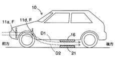
実施の形態1を図1~図9を参照しながら説明する。非接触電力伝送システム100は、受電装置13および送電装置20を有する。図1に示す車両10は、走行の一部または全部に電力を必要とするハイブリッド自動車(Hybrid Vehicle)や電気自動車(Electric Vehicle)などが該当する。この車両10は、ラジエータファン11a,コンデンサファン11d,制御システム12,受電装置13,電池14などを有する。
実施の形態1を図1~図9を参照しながら説明する。非接触電力伝送システム100は、受電装置13および送電装置20を有する。図1に示す車両10は、走行の一部または全部に電力を必要とするハイブリッド自動車(Hybrid Vehicle)や電気自動車(Electric Vehicle)などが該当する。この車両10は、ラジエータファン11a,コンデンサファン11d,制御システム12,受電装置13,電池14などを有する。
ラジエータファン11aとコンデンサファン11dは、いずれも「ファンF」に相当し、車両10のキャビン11cよりも前方側にあるコンパートメント11bに備えられる。コンパートメント11b内には、当該コンパートメント11b内の温度を検出する温度センサ18を備えてもよい(図3を参照)。ラジエータファン11aは、車両10に備えられるラジエータ(図示せず)を冷却する際に用いられる。コンデンサファン11dは、車両10に備えられる空調用コンデンサ(図示せず)を冷却する際に用いられる。
制御システム12は、車両10全体の制御を司るシステムであり、例えばECU(Electronic Control Unit)やコンピュータ等を含む。受電装置13は、後述する送電装置20との間において非接触で電力伝送を行う受電側要素であって、受電制御部15や受電パッド16などを含む。受電制御部15は、受電パッド16で受電した電力について、電池14に蓄電したり、制御システム12との間で通信したりするなどの制御を行う。受電制御部15の構成例については後述する(図6を参照)。受電パッド16は、非接触で電力伝送を行う要素(巻線やコンデンサ等)を含む。
電池14は、蓄電と放電が行えれば種類を問わず、例えばリチウムイオン電池や鉛蓄電池などのような二次電池が該当する。この電池14には、充電圧に基づいて充電要求等の信号を出力する電池ECUを含めてもよい。
送電装置20は、上述した受電装置13との間において非接触で電力伝送を行う送電側要素であって、送電パッド21や送電制御部22などを含む。送電パッド21は、車両10の通路(図1、P参照)に設けられ、非接触で電力伝送を行う要素(巻線やコンデンサ等)を含む。送電制御部22は、電力源30から供給される電力を送電パッド21に出力して電力伝送の送電制御を行う。送電制御部22の構成例については後述する(図5を参照)。
受電パッド16と送電パッド21は、いずれも「電力伝送用パッド」に相当する。これらの受電パッド16と送電パッド21は、巻線とコンデンサが所定の周波数で共振するように設定される点を除けば、同じ構成でもよく、異なる構成でもよい。
ラジエータファン11aおよびコンデンサファン11dのうちで一方または双方のファンFが駆動されると、図2に破線で示す矢印D1,D2のような風や、図3に破線で示す矢印D3のような風が生じる。こうして生じる風は、受電パッド16および送電パッド21のうちで一方または双方を冷却する。なお、ファンFを駆動しても、受電パッド16や送電パッド21の冷却に寄与しない風もあり得る。
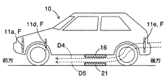
上述したラジエータファン11aやコンデンサファン11dに加えて、図4に示す後方ファン11eを車両10の後方側(例えばトランクルーム等)に備えてもよい。ファンFに相当する後方ファン11eの駆動により、図4に破線で示す矢印D4,D5のような風が生じて、受電パッド16および送電パッド21のうちで一方または双方を冷却する。
図5に示す送電制御部22は、充電ECU22a,制御回路22b,通信機22c,送電回路22d,電流センサ22eなどを有する。これらの要素のうちで一以上の要素は、送電制御部22の外部に備えてもよい。
充電ECU22aは、地上側のECUであり、電池14への充電に関する所要の制御を行う。例えば、電池14(特に電池ECU)から出力されて通信機22cや通信機15cを経て伝達される充電要求を制御回路22bに伝達する制御を含む。
制御回路22bは、必要に応じて温度推定部22b1が備えられ、送電装置20全体の制御を司る。この制御回路22bは、温度センサ23で検出される送電パッド21の温度T1や、電流センサ22eで検出される送電パッド21(具体的にはコイル)に流れる電流I1などに基づいて、送電やファンFの駆動等の制御を行う。また、充電ECU22aから伝達される充電要求に基づいて、電池14に充電するために電力源30から供給される電力を受けて送電パッド21による電力伝送の制御を行う。温度センサ23や温度推定部22b1は、いずれも温度特定部TSに相当する。
温度推定部22b1は、電流センサ22eで検出された電流I1に基づいて、送電パッド21(具体的にはコイル)の温度T1を推定する。温度T1の推定形態は問わない。電流I1と温度T1との相関関係は、テーブルやマップ等に記録したり、関数式で定義したりしておくとよい。
通信機22cは、後述する受電制御部15Aに備える通信機15cとの間で通信を行う。送電回路22dは、コンバータやインバータを含み、電力源30から供給される電力を受けて、送電パッド21による電力伝送の制御を行う。
図6に示す受電制御部15Aは、受電制御部15の一例であり、充電ECU15a,制御回路15b,通信機15c,受電回路15d,電流センサ15eなどを有する。これらの要素のうちで一以上の要素は、受電制御部15Aの外部に備えてもよい。
充電ECU15aは、車両10側のECUであり、電池14への充電に関する所要の制御を行う。例えば、制御システム12や制御回路15bとの間で通信制御を行う。また、ラジエータファン11a,コンデンサファン11d,後方ファン11eのうちで一以上のファンFを駆動制御する。さらに、電池14(特に電池ECU)から出力されて伝達される充電要求を、制御回路15bに伝達したり、通信機22cや通信機15cを経て制御回路22bに伝達したりする制御を含む。
制御回路15bは、必要に応じて温度推定部15b1が備えられ、受電装置13全体の制御を司る。この制御回路15bは、温度センサ17で検出される受電パッド16の温度T2や、温度センサ18で検出されるコンパートメント11b内の温度T3、電流センサ22eで検出される受電パッド16(具体的にはコイル)に流れる電流I2などに基づいて、受電やファンFの駆動等などの制御を行う。温度センサ17,18や温度推定部15b1は、いずれも温度特定部TSに相当する。
温度推定部15b1は、温度T2,T3などの温度Tを推定する。温度T2,T3の推定形態は問わない。例えば、電流センサ15eで検出された電流I2に基づいて、送電パッド21(具体的にはコイル)の温度T2を推定する。制御情報CIに含まれる空調機器(エアコンやヒーター等)の消費電力に基づいて温度T3を推定する。電流I2と温度T2との相関関係や、消費電力と温度T3の相関関係は、テーブルやマップ等に記録したり、関数式で定義したりしておくとよい。
通信機15cは、上述した通信機22cの間で通信を行う。受電回路15dは、コンバータを含み、受電パッド16で生じる電力を電池14に蓄電する制御などを行う。
上述した受電制御部15A(特に制御回路15b)や送電制御部22(特に制御回路22b)において実現される処理について、図7~図9を参照しながら説明する。受電制御部15Aは受電パッド16を対象とし、送電制御部22は送電パッド21を対象とする点が相違するに過ぎない。よって、以下では受電制御部15Aにおいて実現される処理を代表して説明する。
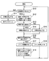
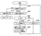
図7に示す充電処理(電力伝送処理)において、まず電池14への充電要求があるか否かを判別する〔S10〕。もし充電要求がなければ(NO)、受電パッド16と送電パッド21との間で電力伝送を行って電池14に充電しているか否かを問わず、充電を停止し〔S11〕、充電処理を終了(あるいはリターン)する。
S10で充電要求があれば(YES)、現在の温度Tを特定する〔S12〕。温度Tは、温度センサで検出して特定してもよく、温度推定部15b1,22b1で推定して特定してもよい。温度センサの例では、温度センサ17,23で検出する温度T2,T1や、温度センサ18で検出する温度T3などが該当する。温度推定部15b1,22b1の例は、電流センサ15e,22eで検出される電流I2,I1に基づいて推定する温度T2,T1や、制御情報CIに含まれる空調機器(エアコンやヒーター等)の消費電力に基づいて推定する温度T3などが該当する。S12では、検出または推定された温度T1~T3のうちで、一以上の温度Tを特定する。
S12で特定した温度Tが充電可能か否かを判別する〔S13〕。もし充電可能な温度Tであれば(YES)、電池14への充電を開始(再開を含む)する〔S14〕。これに対して充電に適さない温度Tであれば(NO)、電池14への充電を停止する〔S15〕。
続いて、S12で特定した温度Tが冷却条件を満たすか否かを判別する〔S16〕。冷却条件は、ファンFの駆動によって送電パッド21や受電パッド16を冷却するための条件であれば任意に設定してよい。例えば、温度T2,T1が温度閾値Tthを超えているか否か、温度T3,T4が所定温度Tx以下であるか否かなどが該当する。温度閾値Tthや所定温度Txは、それぞれ任意の値を設定してよい。なお、前者の温度閾値Tthには、後述する図17に示す送電パッド21の温度閾値Tth1や受電パッド16の温度閾値Tth2を含めてもよい。
もし温度Tが冷却条件を満たせば(YES)、パッド(受電パッド16や送電パッド21)に風を送るようにファンFを駆動(再駆動を含む;正回転)する〔S17〕。ただし、冷却条件を満たしていても、制御システム12から伝達される車両10に関する情報(例えば走行速度や温度等)に基づいて、所定条件を満たすまでファンFからパッドに風を送らないように制御してもよい。例えば、コンパートメント11b内の熱を車両10の外(パッドと反対側)へ排出するためにファンFを逆回転するように駆動する制御や、ファンFを停止する制御などが該当する。所定条件は任意に設定してよい。例えば、コンパートメント11bの温度T3が所定温度Tx以下になること、停止した時点から所定時間を経過すること等が該当する。所定条件を満たせば、ファンFを駆動してパッドに風を送って冷却する。
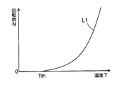
S17におけるファンFの駆動にあたっては、温度Tに応じて冷却能力を変化させるとよい〔S19〕。具体的には、ラジエータファン11a,コンデンサファン11d,後方ファン11eのうちで一以上のファンFを選択する。また、選択したファンFの回転数を変える。温度Tと回転数Nの関係例を図8に特性線L1で示す。温度閾値Tthよりも温度Tが高くなるにつれて回転数Nを増やす。回転数Nが増加すると冷却能率ηも変化する。回転数Nと冷却能率ηの関係例を図9に特性線L2で示す。要するに、温度Tが高くなるにつれて、各ファンの駆動によって生じる風量の総量が増加してゆくように制御する。ただし、ラジエータファン11a,コンデンサファン11dと後方ファン11eとでは風向きが逆であるので(図2,図4を参照)、車両10に向かって吹く風(すなわち自然風)の風向きと同じになるように切り替えるとよい。
一方、S16で温度Tが冷却条件を満たさなければ(NO)、ファンFを停止する〔S18〕。S18,S19を実行した後は、電池14への充電と、受電パッド16や送電パッド21の冷却とを継続するために、S10に戻る。
〔実施の形態2〕
実施の形態2は図10,図11を参照しながら説明する。なお図示および説明を簡単にするため、特に明示しない限り、実施の形態1で用いた要素と同一の要素には同一の符号を付して説明を省略する。よって、主に実施の形態1と相違する点を説明する。
実施の形態2は図10,図11を参照しながら説明する。なお図示および説明を簡単にするため、特に明示しない限り、実施の形態1で用いた要素と同一の要素には同一の符号を付して説明を省略する。よって、主に実施の形態1と相違する点を説明する。
図10に示す充電処理(電力伝送処理)は、図7に示す充電処理に代えて実行される。図10は図7と比べて、S16に代えてS20,S21を実行する点が相違する。
S14,S15を実行した後、S12で特定した温度Tが第1温度閾値THを超えているか否かを判別したり〔S20〕、同じく温度Tが第2温度閾値TLを下回っているか否かを判別したりする〔S21〕。
温度Tが第1温度閾値THを超えていれば(T>TH;S20でYES)、ファンFを駆動し〔S17〕、温度Tに応じて冷却能力を変化させる〔S19〕。これに対して、温度Tが第2温度閾値TLを下回っていれば(T<TL;S20でNO,S21でYES)、ファンFを停止する〔S18〕。
温度Tが第1温度閾値THと第2温度閾値TLの間であれば(TL≦T≦TH;S20,S21でともにNO)、現時点におけるファンFの状態(駆動や停止)を維持して、S10に戻る。
図10の充電処理を実行すると、温度Tに応じたファンFの駆動は図11のようになる。図11に示す特性線L3は、温度Tの一変化例である。時刻t1,t3,t5にはそれぞれ温度Tが第1温度閾値THを超えるので(S20でYES)、ファンFを回転数N1で駆動する(S17,S19)。時刻t2,t4,t6にはそれぞれ温度Tが第2温度閾値TL以下になるので(S20,S21でNO)、ファンFを停止する(S18)。よって、ファンFの間欠運転が行える。
図11の制御例では、ファンFの回転数Nを回転数N1で固定したが、二点鎖線で示すように回転数Nを増加させてもよい。温度Tが第2温度閾値TLを超えている期間が長くなるにつれて回転数Nを増やすことで、冷却能力が高められる。
〔実施の形態3〕
実施の形態3は図12,13を参照しながら説明する。なお図示および説明を簡単にするため、特に明示しない限り、実施の形態1,2で用いた要素と同一の要素には同一の符号を付して説明を省略する。よって、主に実施の形態1,2と相違する点を説明する。
実施の形態3は図12,13を参照しながら説明する。なお図示および説明を簡単にするため、特に明示しない限り、実施の形態1,2で用いた要素と同一の要素には同一の符号を付して説明を省略する。よって、主に実施の形態1,2と相違する点を説明する。
図12に示す充電処理(電力伝送処理)は、図7に示す充電処理に代えて実行される。図12は図7と比べて、S12~S16,S19に代えてS30,S31,S32を実行する点が相違する。
S10で充電要求があれば(YES)、受電パッド16に流れる電流I2および送電パッド21に流れる電流I1のうちで一方または双方の電流Iを検出する〔S12〕。電流I2は電流センサ22eによって検出し(図5を参照)、電流I1は電流センサ15eによって検出する(図6を参照)。
S30で検出した電流Iが電流閾値Ithを超えているか否かを判別する〔S31〕。電流閾値Ithには任意の値を設定してよく、図7,図8に示す温度閾値Tthに対応する。もし電流Iが温度閾値Tthを超えているならば(YES)、ファンFを駆動する〔S17〕。これに対して、S31で電流Iが電流閾値Ith以下であれば(NO)、ファンFを停止する〔S18〕。S18,S32を実行した後は、図7と同様にS10に戻る。
S17におけるファンFの駆動にあたっては、電流Iに応じて冷却能力を変化させるとよい〔S32〕。S32は、温度Tが電流Iに変わる点を除いて、S19と同様に行ってよい。電流Iと回転数Nの関係例を図13に特性線L4で示す。電流閾値Ithよりも電流Iが大きくなるにつれて、回転数Nを増やす。
図示を省略するが、図10に示す充電処理において、相関関係がある温度Tを電流Iに読み替えて適用する構成としてもよい。すなわち、電流Iが第1電流閾値を超えるとファンFを駆動し、電流Iが第2電流閾値以下になるとファンFを停止する制御を行う。第1電流閾値は第1温度閾値THに対応し、第2電流閾値は第2温度閾値TLに対応する。このように構成しても、図11に示すようなファンFの間欠運転が行える。
〔実施の形態4〕
実施の形態4は図14を参照しながら説明する。なお図示および説明を簡単にするため、特に明示しない限り、実施の形態1~3で用いた要素と同一の要素には同一の符号を付して説明を省略する。よって、主に実施の形態1~3と相違する点を説明する。
実施の形態4は図14を参照しながら説明する。なお図示および説明を簡単にするため、特に明示しない限り、実施の形態1~3で用いた要素と同一の要素には同一の符号を付して説明を省略する。よって、主に実施の形態1~3と相違する点を説明する。
図14に示す車両10は、図1,図2に示す車両10と比べて、さらにダクト11f,11gを備える。ダクト11fは、ラジエータファン11aやコンデンサファン11dの駆動によって生じる風が受電パッド16に向かうように風向きを調整する。この調整により、図14に破線で示す矢印D6のように風が流れて、受電パッド16を冷却する。ダクト11f,11gは、新たに車両10に取り付けてもよく、車両10の構造部分(例えばフレーム部分など)を利用してもよい。
ダクト11gは、ラジエータファン11aやコンデンサファン11dの駆動によって生じる風が送電パッド21に向かうように風向きを調整する。この調整により、図14に破線で示す矢印D7のように風が流れて、送電パッド21を冷却する。
上述したダクト11f,11gのうちで一方または双方を車両10に備えると、受電パッド16や送電パッド21の冷却をより確実に行える。
〔実施の形態5〕
実施の形態5は図15~図18を参照しながら説明する。なお図示および説明を簡単にするため、特に明示しない限り、実施の形態1~4で用いた要素と同一の要素には同一の符号を付して説明を省略する。よって、主に実施の形態1~4と相違する点を説明する。
実施の形態5は図15~図18を参照しながら説明する。なお図示および説明を簡単にするため、特に明示しない限り、実施の形態1~4で用いた要素と同一の要素には同一の符号を付して説明を省略する。よって、主に実施の形態1~4と相違する点を説明する。
図15に示す車両10は、図1,図2に示す車両10と比べて、さらにダクト11hを備える。ダクト11hは、スロットル11i,受電側風向口Ex1,送電側風向口Ex2などを有する。このダクト11hは、新たに車両10に備えてもよく、一部または全部について車両10の構造部分(例えばフレーム部分など)を利用してもよい。
スロットル11iは、「流量調整部」に相当し、制御システム12や充電ECU15aによって姿勢(角度)が制御可能に構成される(後述する図16を参照)。このスロットル11iは、姿勢に応じて受電側風向口Ex1と送電側風向口Ex2に分けて送る流量(風量)を調整する。
受電側風向口Ex1は、図14に示すダクト11fに相当し、ラジエータファン11aの駆動によって生じる風が受電パッド16に向かうように風向きを調整する。送電側風向口Ex2は、図14に示すダクト11gに相当し、ラジエータファン11aの駆動によって生じる風が送電パッド21に向かうように風向きを調整する。
図15に示すダクト11hは、ラジエータファン11aの駆動によって生じる風を調整する例を示す。図示しないが、コンデンサファン11dの駆動によって生じる風を調整する構成としてもよく、双方の駆動によって生じる風を調整する構成としてもよい。
図16に示す受電制御部15Bは、受電制御部15の一例であり、図6に示す受電制御部15Aに代わる構成例である。この受電制御部15Bは、受電制御部15Aと同じ構成であるが、充電ECU15aと制御回路15bの役割が相違する。
本構成例における充電ECU15aは、制御回路15bから伝達される信号に基づいて、ファンFの駆動を制御するとともに、スロットル11iの姿勢を制御する。同様に、制御回路15bは、制御システム12を介して、ファンFの駆動を制御するとともに、スロットル11iの姿勢を制御する。すなわち、充電ECU15aおよび制御回路15bのうちで一方または双方がスロットル11iの姿勢制御を行う。
風量Q1,Q2の調整について、図17と図18を参照しながら説明する。風量Q1は、受電側風向口Ex1から送電パッド21に向けて吹き出す風の流量である。風量Q2は、送電側風向口Ex2から受電パッド16に向けて吹き出す風の流量である。
図17には、受電パッド16にかかる温度T2および温度閾値Tth2と、送電パッド21にかかる温度T1および温度閾値Tth1とを示す。温度閾値Tth2,Tth1にはそれぞれ任意の値を設定してよい。すなわち図17ではTth1>Tth2の設定例を示すが、Tth1=Tth2で設定してもよく、Tth1<Tth2で設定してもよい。温度T2と温度閾値Tth2の温度差をΔT2(=T2-Tth2)とし、温度T1と温度閾値Tth1の温度差をΔT1(=T1-Tth1)とする。
図18に示す充電処理(電力伝送処理)は、図7に示す充電処理に代えて実行される。図10は図7と比べて、S16に代えてS20,S21を実行する点が相違する。
S14,S15を実行した後、S12で特定した温度T(T2,T1)が冷却条件を満たすか否かを判別する〔S16〕。具体的には、温度T2が温度閾値Tth2を超えるか(T2>Tth2)、温度T1が温度閾値Tth1を超える場合には(T1>Tth1)、温度Tが温度閾値Tthを超える(つまり冷却条件を満たす)と判別する。
温度Tが温度閾値Tthを超えていれば(S16でYES)、ファンFを駆動し〔S17〕、二点鎖線で示すように温度差ΔT2,ΔT1に応じて冷却能力を変化させる〔S19〕。図17のS19は必要に応じて実行してよく、図7のS19に示す温度Tに代わる温度差ΔT2,ΔT1に基づいて実行する。これに対して、温度Tが温度閾値Tth以下になる(つまり冷却条件を満たさない)と(S16でNO)、ファンFを停止する〔S18〕。
風量Q1,Q2の調整は、S17(あるいはS19)の後に実行する。まず、図17に示すように温度差ΔT1,ΔT2を求め〔S50〕、温度差ΔT1が温度差ΔT2を超えているか否かを判別する〔ΔT1>ΔT2;S51〕。もし温度差ΔT1が温度差ΔT2を超えているならば(YES)、風量Q1が風量Q2よりも多くなるようにスロットル11iの姿勢を調整する〔Q1>Q2;S52〕。この調整により、送電パッド21を優先的に冷却することができる。
一方、温度差ΔT1が温度差ΔT2以下であれば(S51でNO)、風量Q2が風量Q1よりも多くなるようにスロットル11iの姿勢を調整する〔Q2>Q1;S53〕。この調整により、受電パッド16を優先的に冷却することができる。
上述したS51~S53に代えて、図19に示すS54を実行してもよい。S54では、温度差ΔT1と温度差ΔT2との比率に基づいて風量Q1と風量Q2の比率を変えるようにスロットル11iの姿勢を調整する。具体的には、S50で求めた温度差ΔT1と温度差ΔT2とに基づいて、ΔT1:ΔT2=Q1:Q2となるようにスロットル11iの姿勢を制御する。こうすれば各パッドの温度差に応じて両パッドを冷却できる。
図示しないが、所要の条件を満たせば、風量Q1と風量Q2が同じになるようにスロットル11iの姿勢を調整してもよい(Q1=Q2)。所要の条件は任意に設定してよく、例えば温度差ΔT1と温度差ΔT2が同じ場合や(ΔT1=ΔT2)、温度差ΔT1と温度差ΔT2との差分値(|ΔT1-ΔT2|)が許容範囲(Δx)内である場合(|ΔT1-ΔT2|≦Δx)などが該当する。こうすれば両パッドを同等に冷却できる。
図示を省略するが、図18に示す充電処理において、相関関係がある温度Tを電流Iに読み替えて適用する構成としてもよい。すなわち、電流Iが第1電流閾値を超えるとファンFを駆動し、電流Iが第2電流閾値以下になるとファンFを停止する制御を行う。第1電流閾値は第1温度閾値THに対応し、第2電流閾値は第2温度閾値TLに対応する。このように構成しても、図11に示すようなファンFの間欠運転が行える。
〔他の実施の形態〕
以上では本開示を実施するための形態について実施の形態1~5に従って説明したが、本開示は当該形態に何ら限定されるものではない。言い換えれば、本開示の要旨を逸脱しない範囲内において、種々なる形態で実施することもできる。例えば、次に示す各形態を実現してもよい。
以上では本開示を実施するための形態について実施の形態1~5に従って説明したが、本開示は当該形態に何ら限定されるものではない。言い換えれば、本開示の要旨を逸脱しない範囲内において、種々なる形態で実施することもできる。例えば、次に示す各形態を実現してもよい。
上述した実施の形態1~5では、ファンFとしてコンパートメント11bに備えるラジエータファン11aやコンデンサファン11dを適用する構成とした(図1~図4,図14,図15を参照)。この形態に代えて、ラジエータファン11aやコンデンサファン11dを除いて、コンパートメント11bに備えられる他のファンFを用いてもよく、他のファンFを併用してもよい。ファンFの種類が相違するに過ぎないので、実施の形態1~5と同様の作用効果が得られる。
上述した実施の形態1~5では、ファンFの駆動によって生じる風を受電パッド16や送電パッド21に当てて冷却する構成とした(図1~図4,図14,図15を参照)。この形態に加えて、水(雨水,空調時に生じる水など)で受電パッド16や送電パッド21に濡らして冷却する構成としてもよい。具体的には図20に示すように、貯留部材11jや水供給部材11kを車両10に備える。貯留部材11jは、水を貯留しておく部材である。水供給部材11kは、貯留部材11jに貯留されている水を放出して受電パッド16や送電パッド21を濡らす部材である。この水供給部材11kは必要に応じて備えられ、例えばパイプ,放水部材,噴霧器などが該当する。温度Tや電流Iに応じて水供給部材11kから放出や噴霧等する水量を制御してもよい。受電パッド16や送電パッド21を水で濡らして、気化熱による冷却を行う。受電パッド16や送電パッド21を水で濡らしてから、ファンFの駆動によって生じる風を当てると、効果的に冷却を行える。
上述した実施の形態1~5では、受電パッド16と送電パッド21をそれぞれ一つ備える構成とした(図1を参照)。この形態に代えて、受電パッド16と送電パッド21がそれぞれ複数のパッドを有し、複数のパッドがそれぞれ対面(対向)するように構成してもよい。受電パッド16と送電パッド21の数が相違するに過ぎないので、実施の形態1~5と同様の作用効果が得られる。
上述した実施の形態1~5では、受電パッド16や送電パッド21に備えるコイル(巻線)の一方に電流を流して発生させる磁束を媒介して隣接した他方に起電力が発生する電磁誘導を用いた電磁誘導方式を適用する構成とした(図1を参照)。この形態に代えて、電流を電磁波に変換しアンテナを介して送受信する電波方式を適用してもよく、電磁界の共鳴現象を利用した電磁界共鳴方式を適用してもよい。いずれの方式も相互誘導作用によって非接触で電力伝送を行えるので、実施の形態1~5と同様の作用効果が得られる。
上述した実施の形態1~5では、電力伝送によって電池14を充電する構成とした(図1を参照)。この形態に代えて、電力を受けて作動(電池14以外の充電を含む)する他の機器に電力を供給してもよい。他の機器は車両10に備えるか否かを問わない。電力供給の対象が相違するに過ぎないので、実施の形態1~5と同様の作用効果が得られる。
上述した実施の形態1~5では、受電制御部15に制御回路15bを備えるとともに、送電制御部22に制御回路22bを備える構成とした(図5,図6を参照)。この形態に代えて、制御回路15bおよび制御回路22bのうちでいずれか一方の制御回路を備える構成としてもよい。この場合には、制御回路15bと制御回路22bで行う制御の全てを担う。制御回路の数が少ない分だけコストを低減できる。その他については、制御回路の数が相違するに過ぎないので、実施の形態1~5と同様の作用効果が得られる。
上述した実施の形態1~5では、車両10はハイブリッド自動車や電気自動車に適用する構成とした(図1を参照)。この形態に代えて、電池14を備える燃料電池自動車(Fuel Cell Vehicle)に適用する構成としてもよい。燃料である水素がタンクから無くなって燃料電池で発電できなくなっても、電池14の電力によって車両10を走行させることができる。車両10の種類が相違するに過ぎないので、実施の形態1~5と同様の作用効果が得られる。
上述した実施の形態5では、流量調整部としてスロットル11iを適用する構成とした(図15を参照)。この形態に代えて、スロットル11i以外であって他の部材を適用する構成としてもよい。他の部材は、例えばダクト11hの通路を開閉する弁や蓋などが該当する。他の部材を用いても受電側風向口Ex1と送電側風向口Ex2に送る風量Q1,Q2を調整できるので、実施の形態5と同様の作用効果が得られる。
〔作用効果〕
上述した実施の形態1~5および他の実施の形態によれば、以下に示す各効果を得ることができる。
上述した実施の形態1~5および他の実施の形態によれば、以下に示す各効果を得ることができる。
(1)非接触電力伝送システム100において、受電制御部15は、電力伝送を行う際に車両10に備えられるファンF(ラジエータファン11aやコンデンサファン11d等)を駆動し、ファンFの駆動によって生じる風で受電パッド16および送電パッド21のうちで一方または双方を冷却する制御を行う構成とした(図1~図4,図14,図15,図20を参照)。この構成によれば、車両10に備えられるファンFを用いて受電パッド16や送電パッド21を冷却するので、従来よりもコストを低減することができる。また、外気の温度で冷却するので、電池14への充電を行う際に確実に受電パッド16や送電パッド21の冷却が行える。
(2)ファンF(ラジエータファン11a,コンデンサファン11d)は、車両10のキャビン11cよりも前方側のコンパートメント11bに備えられる構成とした(図1~図4,図14,図15,図20を参照)。この構成によれば、既存のファンFを利用するので、コストを低減することができる。
(3)ファンFは、ラジエータファン11aおよびコンデンサファン11dのうちで一方または双方を含む構成とした(図1~図4,図14,図15,図20を参照)。この構成によれば、ラジエータファン11aやコンデンサファン11dはほとんどの車両10に備えているので、受電パッド16や送電パッド21の冷却に有効利用できる。
(4)ファンFの駆動によって生じる風が受電パッド16および送電パッド21のうちで一方または双方に向けて風向きを調整するダクト11f,11g,11hを有する構成とした(図14,図15を参照)。この構成によれば、ファンFの駆動によって生じる風をダクト11f,11g,11hによって受電パッド16や送電パッド21に向けて送ることができる。よって、ダクト11f,11g,11hが無い場合に比べて、受電パッド16や送電パッド21の冷却をより確実に行える。
(5)受電パッド16および送電パッド21のうちで一方または双方にかかる温度T(T1,T2)を検出または推定して特定する温度特定部TSを有し、受電制御部15は温度特定部TSによって特定される温度Tに基づいてファンFの駆動を制御する構成とした(図7,図10,図18を参照)。この構成によれば、受電パッド16や送電パッド21の温度Tに応じてファンFを駆動するので、受電パッド16や送電パッド21の冷却をより確実に行える。
(6)受電パッド16および送電パッド21にかかる温度T(T1,T2)を検出または推定して特定する温度特定部TSと、ファンFの駆動によって生じる風について、受電パッド16および送電パッド21に向かう風の流量(風量Q1,Q2)を調整するスロットル11i(流量調整部)とを有し、受電制御部15は温度特定部TSによって特定される温度Tに基づいてスロットル11iを制御する構成とした(図18を参照)。この構成によれば、受電パッド16に向けて吹き出す風量Q1と送電パッド21に向けて吹き出す風量Q2とをスロットル11iの姿勢で調整するので、受電パッド16または送電パッド21の一方を優先的に冷却することができる。
(7)送電パッド21の温度閾値Tth1と受電パッド16の温度閾値Tth2が設定され、受電制御部15は、温度特定部TSによって特定される送電パッド21の温度T1と温度閾値Tth1との温度差ΔT1と、温度特定部TSによって特定される受電パッド16の温度T2と温度閾値Tth2との温度差ΔT2とに基づいて、スロットル11iを制御する構成とした(図17,図18,図19を参照)。この構成によれば、送電パッド21にかかる温度差ΔT1と受電パッド16にかかる温度差ΔT2に応じて両パッドを冷却できる。すなわち、温度差が大きなパッドを優先して冷却できる。
(8)受電制御部15は、温度特定部TSによって特定される温度T(T1,T2)が、第1温度閾値THを超えるとファンFを駆動し、第1温度閾値THよりも低い第2温度閾値TLを下回るとファンFを停止する制御を行う構成とした(図10,図11を参照)。この構成によれば、温度Tが第1温度閾値THを超えるとファンFを駆動し、第2温度閾値TLを下回るとファンFを停止するので、ファンFの間欠運転が行える。よって、ファンFの駆動に必要な電力を連続運転よりも低く抑えることができる。
(9)温度特定部TSは、温度センサ17,23、および、受電パッド16および送電パッド21のうちで一方または双方に流れる電流I(I1,I2)に基づいて温度T(T1,T2)を推定する温度推定部15b1である構成とした(図5,図6,図16を参照)。この構成によれば、温度センサ17,23を備える場合は、受電パッド16や送電パッド21の温度Tを的確に得ることができる。温度推定部15b1を備える場合は、温度センサ17,23が無い場合でも温度Tを得ることができる。いずれにせよ温度Tに基づいて受電パッド16や送電パッド21の冷却を行うことができる。
(10)受電制御部15は、ファンFの駆動を回転数Nで制御する構成とした(図8,図11,図13を参照)。この構成によれば、受電パッド16や送電パッド21の温度Tに応じてファンFの回転数Nが制御されるので、冷却不足や冷却過剰を防止できる。
(11)受電装置13は充電ECU15aを含み、充電ECU15aは、電力伝送を行う際に車両10に備えられるファンFを駆動し、ファンFの駆動によって生じる風で受電パッド16および送電パッド21のうちで一方または双方を冷却する制御を行う構成とした(図6,図16を参照)。この構成によれば、電池14からの充電要求等に応じて、電池14への充電やパッドの冷却を容易に制御することができる。
(12)受電制御部15は、所定条件を満たすまで、受電パッド16および送電パッド21のうちで一方または双方にファンFから風を送らないように制御を行う構成とした(図7,図10,図18のS17を参照)。この構成によれば、車両10の走行等に伴って熱せられる部品(例えばエンジン,マフラー,回転電機等)によって、ファンFから受電パッド16や送電パッド21に熱風が送られて加温するのを阻止する。よって、受電パッド16や送電パッド21について意図しない加温を防止できる。なお、回転電機は、回転する部位(例えば軸やシャフト等)を有する機器であれば任意である。例えば、発電機,電動機,電動発電機等が該当する。
(13)温度特定部TSはファンFが配置されるコンパートメント11bの温度T3を検出または推定して特定し、受電制御部15は温度特定部TSによって特定される温度T3が所定温度Tx以下になると、受電パッド16や送電パッド21にファンFから風を送るように制御を行う構成とした(図7,図18,図19のS16,S17を参照)。この構成によれば、検出または推定される温度T3が所定温度Tx以下のときに限ってファンFを駆動し、受電パッド16や送電パッド21に風を送って冷却する。よって、受電パッド16や送電パッド21について意図しない加温を確実に防止できる。
Claims (13)
- 車両(10)に設けられる受電パッド(16)と、前記受電パッドで受電した電力を制御する受電制御部(15)とを有する受電装置(13)と、
前記車両の通路に設けられる送電パッド(21)と、前記送電パッドに出力して送電する電力を制御する送電制御部(22)とを有する送電装置(20)とを備え、
前記受電パッドと前記送電パッドとを対面させた状態で、非接触で電力伝送を行う非接触電力伝送システム(100)において、
前記受電制御部は、前記電力伝送を行う際に前記車両に備えられるファン(F,11a,11d,11e)を駆動し、前記ファンの駆動によって生じる風で前記受電パッドおよび前記送電パッドのうちで一方または双方を冷却する制御を行う非接触電力伝送システム。 - 前記ファンは、前記車両のキャビン(11c)よりも前方側に備えられる請求項1に記載の非接触電力伝送システム。
- 前記ファンは、ラジエータを冷却する際に用いるラジエータファン(11a)、および、空調用コンデンサを冷却する際に用いるコンデンサファン(11d)のうちで一方または双方を含む請求項2に記載の非接触電力伝送システム。
- 前記ファンの駆動によって生じる風が前記受電パッドおよび前記送電パッドのうちで一方または双方に向けて風向きを調整するダクト(11f,11g,11h)を有する請求項1から3のいずれか一項に記載の非接触電力伝送システム。
- 前記受電パッドおよび前記送電パッドのうちで一方または双方にかかる温度(T1,T2)を検出または推定して特定する温度特定部(TS)を有し、
前記受電制御部は、前記温度特定部によって特定される温度に基づいて、前記ファンの駆動を制御する請求項1から4のいずれか一項に記載の非接触電力伝送システム。 - 前記受電パッドおよび前記送電パッドにかかる温度を検出または推定して特定する温度特定部(TS)と、
前記ファンの駆動によって生じる風について、前記受電パッドおよび前記送電パッドに向かう風の流量を調整する流量調整部(11i)と、を有し、
前記受電制御部は、前記温度特定部によって特定される温度に基づいて、前記流量調整部を制御する請求項1から4のいずれか一項に記載の非接触電力伝送システム。 - 前記送電パッドの温度閾値(Tth1)と前記受電パッドの温度閾値(Tth2)が設定され、
前記受電制御部は、前記温度特定部によって特定される前記送電パッドの温度(T1)と前記温度閾値(Tth1)との温度差(ΔT1)と、前記温度特定部によって特定される前記受電パッドの温度(T2)と前記温度閾値(Tth2)との温度差(ΔT2)とに基づいて、前記流量調整部を制御する請求項5または6に記載の非接触電力伝送システム。 - 前記受電制御部は、前記温度特定部によって特定される温度が、第1温度閾値(TH)を超えると前記ファンを駆動し、前記第1温度閾値よりも低い第2温度閾値(TL)を下回ると前記ファンを停止する制御を行う請求項5から7のいずれか一項に記載の非接触電力伝送システム。
- 前記温度特定部は、温度センサ(17,23)、および、前記受電パッドおよび前記送電パッドのうちで一方または双方に流れる電流(I,I1,I2)に基づいて温度を推定する温度推定部(15b1,22b1)である請求項5から8のいずれか一項に記載の非接触電力伝送システム。
- 前記受電制御部は、前記ファンの駆動を回転数(N)で制御する請求項1から9のいずれか一項に記載の非接触電力伝送システム。
- 前記受電装置は充電ECU(15a)を含み、
前記充電ECUは、前記電力伝送を行う際に前記車両に備えられるファンを駆動し、前記ファンの駆動によって生じる風で前記受電パッドおよび前記送電パッドのうちで一方または双方を冷却する制御を行う請求項1から10のいずれか一項に記載の非接触電力伝送システム。 - 前記受電制御部は、所定条件を満たすまで、前記受電パッドおよび前記送電パッドのうちで一方または双方に前記ファンから風を送らないように制御を行う請求項1から11のいずれか一項に記載の非接触電力伝送システム。
- 前記温度特定部は、前記ファンが配置されるコンパートメント(11b)の温度(T3)を検出または推定して特定し、
前記受電制御部は、前記温度特定部によって特定される前記温度が所定温度(Tx)以下になると、前記ファンから風を送るように制御を行う請求項5から12のいずれか一項に記載の非接触電力伝送システム。
Applications Claiming Priority (2)
| Application Number | Priority Date | Filing Date | Title |
|---|---|---|---|
| JP2015-029572 | 2015-02-18 | ||
| JP2015029572A JP6388164B2 (ja) | 2015-02-18 | 2015-02-18 | 非接触電力伝送システム |
Publications (1)
| Publication Number | Publication Date |
|---|---|
| WO2016132695A1 true WO2016132695A1 (ja) | 2016-08-25 |
Family
ID=56688765
Family Applications (1)
| Application Number | Title | Priority Date | Filing Date |
|---|---|---|---|
| PCT/JP2016/000556 Ceased WO2016132695A1 (ja) | 2015-02-18 | 2016-02-03 | 非接触電力伝送システム |
Country Status (2)
| Country | Link |
|---|---|
| JP (1) | JP6388164B2 (ja) |
| WO (1) | WO2016132695A1 (ja) |
Cited By (1)
| Publication number | Priority date | Publication date | Assignee | Title |
|---|---|---|---|---|
| GB2577568A (en) * | 2018-09-28 | 2020-04-01 | Bombardier Primove Gmbh | Inductive power transfer pad comprising an airflow generating system, arrangement for an inductive power transfer and method for cooling an inductive power |
Families Citing this family (2)
| Publication number | Priority date | Publication date | Assignee | Title |
|---|---|---|---|---|
| JP6940309B2 (ja) * | 2017-06-15 | 2021-09-22 | 株式会社Subaru | バッテリ冷却制御装置及びバッテリ冷却制御方法並びに電動車両 |
| JP2019219107A (ja) * | 2018-06-20 | 2019-12-26 | 株式会社デンソー | 冷却設備及び冷却設備システム |
Citations (2)
| Publication number | Priority date | Publication date | Assignee | Title |
|---|---|---|---|---|
| JP2013135572A (ja) * | 2011-12-27 | 2013-07-08 | Toyota Motor Corp | 非接触受電装置および非接触充電システム |
| JP2015002571A (ja) * | 2013-06-13 | 2015-01-05 | 矢崎総業株式会社 | 給電装置及び給電システム |
-
2015
- 2015-02-18 JP JP2015029572A patent/JP6388164B2/ja active Active
-
2016
- 2016-02-03 WO PCT/JP2016/000556 patent/WO2016132695A1/ja not_active Ceased
Patent Citations (2)
| Publication number | Priority date | Publication date | Assignee | Title |
|---|---|---|---|---|
| JP2013135572A (ja) * | 2011-12-27 | 2013-07-08 | Toyota Motor Corp | 非接触受電装置および非接触充電システム |
| JP2015002571A (ja) * | 2013-06-13 | 2015-01-05 | 矢崎総業株式会社 | 給電装置及び給電システム |
Cited By (2)
| Publication number | Priority date | Publication date | Assignee | Title |
|---|---|---|---|---|
| GB2577568A (en) * | 2018-09-28 | 2020-04-01 | Bombardier Primove Gmbh | Inductive power transfer pad comprising an airflow generating system, arrangement for an inductive power transfer and method for cooling an inductive power |
| US12077057B2 (en) | 2018-09-28 | 2024-09-03 | Enrx Ipt Gmbh | Method and system for cooling of an inductive power transfer pad |
Also Published As
| Publication number | Publication date |
|---|---|
| JP2016152709A (ja) | 2016-08-22 |
| JP6388164B2 (ja) | 2018-09-12 |
Similar Documents
| Publication | Publication Date | Title |
|---|---|---|
| US11292363B2 (en) | Charging system | |
| CN111347833B (zh) | 电动车的温度调节控制系统 | |
| US11075417B2 (en) | Battery cooling control system | |
| CN106169627B (zh) | 用于电气化车辆的车舱和电池冷却控制 | |
| CN102774251B (zh) | 用于电动车辆的空气调节控制设备 | |
| CN106335387B (zh) | 预调节电动车辆 | |
| US9707822B2 (en) | Electric vehicle thermal management system | |
| US8851153B2 (en) | System and method for managing waste heat of electric vehicle | |
| US9212599B2 (en) | Control of compressor outlet pressure based on temperature of thermal load cooled by coolant in electric vehicle | |
| US8677772B2 (en) | Air conditioning system for a vehicle | |
| US20120082871A1 (en) | Thermal Management Controls for a Vehicle Having a Rechargeable Energy Storage System | |
| CN111902303B (zh) | 冷却装置 | |
| KR101628603B1 (ko) | 환경차량용 충전기 냉각시스템 제어 방법 및 냉각시스템 제어기 | |
| US20180272877A1 (en) | Electric Vehicle with Thermal Management System | |
| KR20200009566A (ko) | 배터리 열관리 통합 시스템 및 그 운영방법 | |
| CN103812224A (zh) | 基于历史使用而调整能量存储系统热调节设定点 | |
| KR101755480B1 (ko) | 차량용 쿨링팬 제어방법 | |
| CN108001157B (zh) | 一种电池箱加热系统 | |
| CN109642487A (zh) | 用于车辆中电力单元的冷却系统 | |
| WO2015139663A1 (zh) | 电动车的温控系统 | |
| EP3400146B1 (en) | Thermal management for electrical drive systems | |
| JP6388164B2 (ja) | 非接触電力伝送システム | |
| CN207183468U (zh) | 一种电池加热冷却系统、电动汽车热管理系统及电动汽车 | |
| GB2509308A (en) | Heat transfer arrangement for heating battery | |
| US20140230463A1 (en) | Method for controlling a compressor of a thermal storage heat pump system |
Legal Events
| Date | Code | Title | Description |
|---|---|---|---|
| 121 | Ep: the epo has been informed by wipo that ep was designated in this application |
Ref document number: 16752086 Country of ref document: EP Kind code of ref document: A1 |
|
| NENP | Non-entry into the national phase |
Ref country code: DE |
|
| 122 | Ep: pct application non-entry in european phase |
Ref document number: 16752086 Country of ref document: EP Kind code of ref document: A1 |