WO2016129900A1 - Method and apparatus for transceiving physical broadcast channel in wireless access system supporting machine-type communication - Google Patents
Method and apparatus for transceiving physical broadcast channel in wireless access system supporting machine-type communication Download PDFInfo
- Publication number
- WO2016129900A1 WO2016129900A1 PCT/KR2016/001324 KR2016001324W WO2016129900A1 WO 2016129900 A1 WO2016129900 A1 WO 2016129900A1 KR 2016001324 W KR2016001324 W KR 2016001324W WO 2016129900 A1 WO2016129900 A1 WO 2016129900A1
- Authority
- WO
- WIPO (PCT)
- Prior art keywords
- pbch
- subframe
- mtc
- csi
- transmitted
- Prior art date
Links
Images


Classifications
-
- H—ELECTRICITY
- H04—ELECTRIC COMMUNICATION TECHNIQUE
- H04L—TRANSMISSION OF DIGITAL INFORMATION, e.g. TELEGRAPHIC COMMUNICATION
- H04L5/00—Arrangements affording multiple use of the transmission path
- H04L5/003—Arrangements for allocating sub-channels of the transmission path
- H04L5/0053—Allocation of signaling, i.e. of overhead other than pilot signals
-
- H—ELECTRICITY
- H04—ELECTRIC COMMUNICATION TECHNIQUE
- H04B—TRANSMISSION
- H04B7/00—Radio transmission systems, i.e. using radiation field
- H04B7/24—Radio transmission systems, i.e. using radiation field for communication between two or more posts
- H04B7/26—Radio transmission systems, i.e. using radiation field for communication between two or more posts at least one of which is mobile
- H04B7/2603—Arrangements for wireless physical layer control
-
- H—ELECTRICITY
- H04—ELECTRIC COMMUNICATION TECHNIQUE
- H04B—TRANSMISSION
- H04B7/00—Radio transmission systems, i.e. using radiation field
- H04B7/24—Radio transmission systems, i.e. using radiation field for communication between two or more posts
- H04B7/26—Radio transmission systems, i.e. using radiation field for communication between two or more posts at least one of which is mobile
- H04B7/2612—Arrangements for wireless medium access control, e.g. by allocating physical layer transmission capacity
-
- H—ELECTRICITY
- H04—ELECTRIC COMMUNICATION TECHNIQUE
- H04W—WIRELESS COMMUNICATION NETWORKS
- H04W4/00—Services specially adapted for wireless communication networks; Facilities therefor
- H04W4/30—Services specially adapted for particular environments, situations or purposes
- H04W4/38—Services specially adapted for particular environments, situations or purposes for collecting sensor information
-
- H—ELECTRICITY
- H04—ELECTRIC COMMUNICATION TECHNIQUE
- H04B—TRANSMISSION
- H04B7/00—Radio transmission systems, i.e. using radiation field
- H04B7/02—Diversity systems; Multi-antenna system, i.e. transmission or reception using multiple antennas
- H04B7/04—Diversity systems; Multi-antenna system, i.e. transmission or reception using multiple antennas using two or more spaced independent antennas
- H04B7/06—Diversity systems; Multi-antenna system, i.e. transmission or reception using multiple antennas using two or more spaced independent antennas at the transmitting station
- H04B7/0613—Diversity systems; Multi-antenna system, i.e. transmission or reception using multiple antennas using two or more spaced independent antennas at the transmitting station using simultaneous transmission
- H04B7/0615—Diversity systems; Multi-antenna system, i.e. transmission or reception using multiple antennas using two or more spaced independent antennas at the transmitting station using simultaneous transmission of weighted versions of same signal
- H04B7/0619—Diversity systems; Multi-antenna system, i.e. transmission or reception using multiple antennas using two or more spaced independent antennas at the transmitting station using simultaneous transmission of weighted versions of same signal using feedback from receiving side
- H04B7/0621—Feedback content
- H04B7/0626—Channel coefficients, e.g. channel state information [CSI]
-
- H—ELECTRICITY
- H04—ELECTRIC COMMUNICATION TECHNIQUE
- H04L—TRANSMISSION OF DIGITAL INFORMATION, e.g. TELEGRAPHIC COMMUNICATION
- H04L5/00—Arrangements affording multiple use of the transmission path
- H04L5/003—Arrangements for allocating sub-channels of the transmission path
- H04L5/0048—Allocation of pilot signals, i.e. of signals known to the receiver
-
- H—ELECTRICITY
- H04—ELECTRIC COMMUNICATION TECHNIQUE
- H04W—WIRELESS COMMUNICATION NETWORKS
- H04W4/00—Services specially adapted for wireless communication networks; Facilities therefor
- H04W4/02—Services making use of location information
- H04W4/021—Services related to particular areas, e.g. point of interest [POI] services, venue services or geofences
Definitions
- the present invention relates to a wireless access system supporting Machine Type Communication (MTC), and more particularly, to a method and apparatus for repeatedly transmitting and receiving a physical broadcast channel (PBCH) for an MTC terminal.
- MTC Machine Type Communication
- PBCH physical broadcast channel
- Wireless access systems are widely deployed to provide various kinds of communication services such as voice and data.
- a wireless access system is a multiple access system capable of supporting communication with multiple users by sharing available system resources (bandwidth, transmission power, etc.).
- multiple access systems include code division multiple access (CDMA) systems, frequency division multiple access (FDMA) systems, time division multiple access (TDMA) systems, orthogonal frequency division multiple access (OFDMA) systems, and single carrier frequency (SC-FDMA). division multiple access) system.
- CDMA code division multiple access
- FDMA frequency division multiple access
- TDMA time division multiple access
- OFDMA orthogonal frequency division multiple access
- SC-FDMA single carrier frequency division multiple access
- An object of the present invention is to provide a method for configuring a PBCH for the MTC terminal.
- Another object of the present invention is to provide a method for repeatedly transmitting control information transmitted through a PBCH for an MTC terminal.
- Another object of the present invention is to provide an apparatus supporting these methods.
- the present invention relates to a radio access system supporting machine type communication (MTC), and more particularly, to a method of repeatedly transmitting a physical broadcast channel (PBCH) for an MTC and to provide apparatuses for supporting the same.
- MTC radio access system supporting machine type communication
- PBCH physical broadcast channel
- a method of repeatedly transmitting a physical broadcast channel (PBCH) for an MTC terminal in a wireless access system supporting machine type communication includes: a first PBCH through a legacy PBCH transmission region of a first subframe; And transmitting the second PBCH repeatedly in the first subframe and transmitting the third PBCH repeatedly in the second subframe.
- the control region of the first subframe and the second subframe may be configured such that repetitive transmission of the second PBCH and the third PBCH is not performed.
- a base station for repeatedly transmitting a physical broadcast channel (PBCH) for an MTC terminal in a wireless access system supporting machine type communication may include a transmitter and a processor for supporting repeated transmission of the PBCH.
- the processor controls the transmitter to transmit the first PBCH through the legacy PBCH transmission region of the first subframe; Repeatedly transmitting the second PBCH in the first subframe; It may be configured to repeatedly transmit the third PBCH in the second subframe.
- the control region of the first subframe and the second subframe may be configured such that repetitive transmission of the second PBCH and the third PBCH is not performed.
- the control region may be allocated from the first symbol to the third or fourth symbol of the first slot of the first subframe and the second subframe.
- the third PBCH may not be allocated to the resource element RE to which the reference signal RS is allocated in the second subframe.
- RS is a channel state information reference signal (CSI-RS), and RE is mapped to a CSI-RS configuration commonly used in a frequency division multiplexing scheme (FDD) and a time division multiplexing scheme (TDD) among CSI-RS configurations. It may be an RE to which the CSI-RS is allocated.
- the RE may be allocated to the sixth and seventh symbols in the first slot and the third and fourth or the sixth and seventh symbols in the second slot.
- the second PBCH may be transmitted through the MTC transmission region for the MTC terminal in the first subframe
- the third PBCH may be transmitted through the MTC transmission region for the MTC terminal in the second subframe.
- the first subframe and the second subframe may be consecutive subframes.
- the PBCH can be reliably transmitted to MTC terminals located in poor environments.
- a phase difference value is constant so that the base station and / or the MTC terminal can efficiently and accurately perform frequency tracking and / or frequency offset estimation.
- 1 is a diagram illustrating a physical channel and a signal transmission method using the same.
- FIG. 2 is a diagram illustrating an example of a structure of a radio frame.
- 3 is a diagram illustrating a resource grid for a downlink slot.
- FIG. 4 is a diagram illustrating an example of a structure of an uplink subframe.
- 5 is a diagram illustrating an example of a structure of a downlink subframe.
- FIG. 6 illustrates a subframe structure of an LTE-A system according to cross carrier scheduling used in embodiments of the present invention.
- FIG. 7 is a diagram illustrating an example of an initial access procedure used in an LTE / LTE-A system.
- FIG. 8 is a diagram illustrating one method of transmitting a broadcast channel signal.
- FIG. 9 is a conceptual diagram of a CoMP system operating based on a CA environment.
- FIG. 10 is a diagram illustrating an example of a subframe to which a cell specific reference signal (CRS) is allocated, which can be used in embodiments of the present invention.
- CRS cell specific reference signal
- FIG. 11 is a diagram illustrating an example of subframes in which CSI-RSs that can be used in embodiments of the present invention are allocated according to the number of antenna ports.
- FIG. 12 is a diagram illustrating an example in which legacy PDCCH, PDSCH, and E-PDCCH used in an LTE / LTE-A system are multiplexed.
- FIG. 13 is a diagram for describing a method of repeatedly transmitting a PBCH to an MTC terminal by a base station.
- FIG. 14 is a diagram for describing a method of repeatedly transmitting an MTC PBCH to an MTC terminal.
- FIG. 15 is a means in which the methods described in FIGS. 1 to 14 may be implemented.
- Embodiments of the present invention described in detail below provide methods and apparatuses using heterogeneous network signals to measure the position of a terminal.
- each component or feature may be considered to be optional unless otherwise stated.
- Each component or feature may be embodied in a form that is not combined with other components or features.
- some components and / or features may be combined to form an embodiment of the present invention.
- the order of the operations described in the embodiments of the present invention may be changed. Some components or features of one embodiment may be included in another embodiment or may be replaced with corresponding components or features of another embodiment.
- the base station is meant as a terminal node of a network that directly communicates with a mobile station.
- the specific operation described as performed by the base station in this document may be performed by an upper node of the base station in some cases.
- various operations performed for communication with a mobile station in a network consisting of a plurality of network nodes including a base station may be performed by the base station or network nodes other than the base station.
- the 'base station' may be replaced by terms such as a fixed station, a Node B, an eNode B (eNB), an advanced base station (ABS), or an access point.
- a terminal may be a user equipment (UE), a mobile station (MS), a subscriber station (SS), or a mobile subscriber station (MSS). It may be replaced with terms such as a mobile terminal or an advanced mobile station (AMS).
- UE user equipment
- MS mobile station
- SS subscriber station
- MSS mobile subscriber station
- AMS advanced mobile station
- the transmitting end refers to a fixed and / or mobile node that provides a data service or a voice service
- the receiving end refers to a fixed and / or mobile node that receives a data service or a voice service. Therefore, in uplink, a mobile station may be a transmitting end and a base station may be a receiving end. Similarly, in downlink, a mobile station may be a receiving end and a base station may be a transmitting end.
- Embodiments of the present invention may be supported by standard documents disclosed in at least one of the IEEE 802.xx system, the 3rd Generation Partnership Project (3GPP) system, the 3GPP LTE system, and the 3GPP2 system, which are wireless access systems, and in particular, the present invention.
- Embodiments of the may be supported by 3GPP TS 36.211, 3GPP TS 36.212, 3GPP TS 36.213, 3GPP TS 36.321 and 3GPP TS 36.331 documents. That is, obvious steps or portions not described among the embodiments of the present invention may be described with reference to the above documents.
- all terms disclosed in the present document can be described by the above standard document.
- 3GPP LTE / LTE-A system will be described as an example of a wireless access system in which embodiments of the present invention can be used.
- CDMA code division multiple access
- FDMA frequency division multiple access
- TDMA time division multiple access
- OFDMA orthogonal frequency division multiple access
- SC-FDMA single carrier frequency division multiple access
- CDMA may be implemented with a radio technology such as Universal Terrestrial Radio Access (UTRA) or CDMA2000.
- TDMA may be implemented with wireless technologies such as Global System for Mobile communications (GSM) / General Packet Radio Service (GPRS) / Enhanced Data Rates for GSM Evolution (EDGE).
- GSM Global System for Mobile communications
- GPRS General Packet Radio Service
- EDGE Enhanced Data Rates for GSM Evolution
- OFDMA may be implemented in a wireless technology such as IEEE 802.11 (Wi-Fi), IEEE 802.16 (WiMAX), IEEE 802-20, Evolved UTRA (E-UTRA).
- UTRA is part of the Universal Mobile Telecommunications System (UMTS).
- 3GPP Long Term Evolution (LTE) is part of an Evolved UMTS (E-UMTS) using E-UTRA, and employs OFDMA in downlink and SC-FDMA in uplink.
- LTE-A (Advanced) system is an improved system of the 3GPP LTE system.
- embodiments of the present invention will be described based on the 3GPP LTE / LTE-A system, but can also be applied to IEEE 802.16e / m system and the like.
- a terminal receives information from a base station through downlink (DL) and transmits information to the base station through uplink (UL).
- the information transmitted and received by the base station and the terminal includes general data information and various control information, and various physical channels exist according to the type / use of the information they transmit and receive.
- FIG. 1 is a diagram for explaining physical channels that can be used in embodiments of the present invention and a signal transmission method using the same.
- the initial cell search operation such as synchronizing with the base station is performed in step S11.
- the UE receives a Primary Synchronization Channel (P-SCH) and a Secondary Synchronization Channel (S-SCH) from the base station, synchronizes with the base station, and obtains information such as a cell ID.
- P-SCH Primary Synchronization Channel
- S-SCH Secondary Synchronization Channel
- the terminal may receive a physical broadcast channel (PBCH) signal from the base station to obtain broadcast information in a cell.
- PBCH physical broadcast channel
- the terminal may receive a downlink reference signal (DL RS) in the initial cell search step to confirm the downlink channel state.
- DL RS downlink reference signal
- the UE After completing the initial cell search, the UE receives a physical downlink control channel (PDCCH) and a physical downlink control channel (PDSCH) according to the physical downlink control channel information in step S12. Specific system information can be obtained.
- PDCCH physical downlink control channel
- PDSCH physical downlink control channel
- the terminal may perform a random access procedure as in steps S13 to S16 to complete the access to the base station.
- the UE transmits a preamble through a physical random access channel (PRACH) (S13), a response message to the preamble through a physical downlink control channel and a corresponding physical downlink shared channel. Can be received (S14).
- PRACH physical random access channel
- the UE may perform contention resolution such as transmitting an additional physical random access channel signal (S15) and receiving a physical downlink control channel signal and a corresponding physical downlink shared channel signal (S16). Procedure).
- the UE After performing the above-described procedure, the UE subsequently receives a physical downlink control channel signal and / or a physical downlink shared channel signal (S17) and a physical uplink shared channel (PUSCH) as a general uplink / downlink signal transmission procedure.
- a transmission (Uplink Shared Channel) signal and / or a Physical Uplink Control Channel (PUCCH) signal may be transmitted (S18).
- UCI uplink control information
- HARQ-ACK / NACK Hybrid Automatic Repeat and reQuest Acknowledgement / Negative-ACK
- SR Scheduling Request
- CQI Channel Quality Indication
- PMI Precoding Matrix Indication
- RI Rank Indication
- UCI is generally transmitted periodically through the PUCCH, but may be transmitted through the PUSCH when control information and traffic data should be transmitted at the same time.
- the UCI may be aperiodically transmitted through the PUSCH by the request / instruction of the network.
- FIG. 2 shows a structure of a radio frame used in embodiments of the present invention.
- the type 1 frame structure can be applied to both full duplex Frequency Division Duplex (FDD) systems and half duplex FDD systems.
- FDD Frequency Division Duplex
- One subframe is defined as two consecutive slots, and the i-th subframe includes slots corresponding to 2i and 2i + 1. That is, a radio frame consists of 10 subframes.
- the time taken to transmit one subframe is called a transmission time interval (TTI).
- the slot includes a plurality of OFDM symbols or SC-FDMA symbols in the time domain and a plurality of resource blocks in the frequency domain.
- One slot includes a plurality of orthogonal frequency division multiplexing (OFDM) symbols in the time domain. Since 3GPP LTE uses OFDMA in downlink, the OFDM symbol is for representing one symbol period. The OFDM symbol may be referred to as one SC-FDMA symbol or symbol period.
- a resource block is a resource allocation unit and includes a plurality of consecutive subcarriers in one slot.
- 10 subframes may be used simultaneously for downlink transmission and uplink transmission during each 10ms period. At this time, uplink and downlink transmission are separated in the frequency domain.
- the terminal cannot transmit and receive at the same time.
- the structure of the radio frame described above is just one example, and the number of subframes included in the radio frame, the number of slots included in the subframe, and the number of OFDM symbols included in the slot may be variously changed.
- Type 2 frame structure is applied to the TDD system.
- the type 2 frame includes a special subframe consisting of three fields: a downlink pilot time slot (DwPTS), a guard period (GP), and an uplink pilot time slot (UpPTS).
- DwPTS downlink pilot time slot
- GP guard period
- UpPTS uplink pilot time slot
- the DwPTS is used for initial cell search, synchronization or channel estimation in the terminal.
- UpPTS is used for channel estimation at the base station and synchronization of uplink transmission of the terminal.
- the guard period is a period for removing interference generated in the uplink due to the multipath delay of the downlink signal between the uplink and the downlink.
- Table 1 below shows the structure of the special frame (length of DwPTS / GP / UpPTS).
- FIG. 3 is a diagram illustrating a resource grid for a downlink slot that can be used in embodiments of the present invention.
- one downlink slot includes a plurality of OFDM symbols in the time domain.
- one downlink slot includes seven OFDM symbols, and one resource block includes 12 subcarriers in a frequency domain, but is not limited thereto.
- Each element on the resource grid is a resource element, and one resource block includes 12 ⁇ 7 resource elements.
- the number N DL of resource blocks included in the downlink slot depends on the downlink transmission bandwidth.
- the structure of the uplink slot may be the same as the structure of the downlink slot.
- FIG. 4 shows a structure of an uplink subframe that can be used in embodiments of the present invention.
- an uplink subframe may be divided into a control region and a data region in the frequency domain.
- the control region is allocated a PUCCH carrying uplink control information.
- a PUSCH carrying user data is allocated.
- one UE does not simultaneously transmit a PUCCH and a PUSCH.
- the PUCCH for one UE is allocated an RB pair in a subframe. RBs belonging to the RB pair occupy different subcarriers in each of the two slots.
- the RB pair assigned to this PUCCH is said to be frequency hopping at the slot boundary.
- FIG. 5 shows a structure of a downlink subframe that can be used in embodiments of the present invention.
- up to three OFDM symbols from the OFDM symbol index 0 in the first slot in the subframe are control regions to which control channels are allocated, and the remaining OFDM symbols are data regions to which the PDSCH is allocated. to be.
- a downlink control channel used in 3GPP LTE includes a Physical Control Format Indicator Channel (PCFICH), a PDCCH, and a Physical Hybrid-ARQ Indicator Channel (PHICH).
- PCFICH Physical Control Format Indicator Channel
- PDCCH Physical Hybrid-ARQ Indicator Channel
- PHICH Physical Hybrid-ARQ Indicator Channel
- the PCFICH is transmitted in the first OFDM symbol of a subframe and carries information about the number of OFDM symbols (ie, the size of the control region) used for transmission of control channels within the subframe.
- the PHICH is a response channel for the uplink and carries an ACK (Acknowledgement) / NACK (Negative-Acknowledgement) signal for a hybrid automatic repeat request (HARQ).
- Control information transmitted through the PDCCH is called downlink control information (DCI).
- the downlink control information includes uplink resource allocation information, downlink resource allocation information or an uplink transmission (Tx) power control command for a certain terminal group.
- CA Carrier Aggregation
- LTE system 3rd Generation Partnership Project Long Term Evolution (Rel-8 or Rel-9) system
- MCM multi-carrier modulation
- CC component carrier
- Multi-Carrier Modulation is used.
- LTE-A system a method such as Carrier Aggregation (CA) may be used in which one or more component carriers are combined to support a wider system bandwidth than the LTE system.
- CA Carrier Aggregation
- Carrier aggregation may be replaced with the words carrier aggregation, carrier matching, multi-component carrier environment (Multi-CC) or multicarrier environment.
- the multi-carrier means the aggregation of carriers (or carrier aggregation), wherein the aggregation of carriers means not only merging between contiguous carriers but also merging between non-contiguous carriers.
- the number of component carriers aggregated between downlink and uplink may be set differently.
- the case where the number of downlink component carriers (hereinafter referred to as 'DL CC') and the number of uplink component carriers (hereinafter referred to as 'UL CC') is the same is called symmetric merging. This is called asymmetric merging.
- Such carrier aggregation may be used interchangeably with terms such as carrier aggregation, bandwidth aggregation, spectrum aggregation, and the like.
- Carrier aggregation in which two or more component carriers are combined, aims to support up to 100 MHz bandwidth in an LTE-A system.
- the bandwidth of the combining carrier may be limited to the bandwidth used by the existing system to maintain backward compatibility with the existing IMT system.
- the existing 3GPP LTE system supports ⁇ 1.4, 3, 5, 10, 15, 20 ⁇ MHz bandwidth
- the 3GPP LTE-advanced system i.e., LTE-A
- LTE-A 3GPP LTE-advanced system
- the carrier aggregation system used in the present invention may support carrier aggregation by defining a new bandwidth regardless of the bandwidth used in the existing system.
- the carrier aggregation may be divided into an intra-band CA and an inter-band CA.
- Intra-band carrier merging means that a plurality of DL CCs and / or UL CCs are located adjacent to or in proximity to frequency. In other words, it may mean that the carrier frequencies of the DL CCs and / or UL CCs are located in the same band.
- an environment far from the frequency domain may be referred to as an inter-band CA.
- the terminal may use a plurality of radio frequency (RF) terminals to perform communication in a carrier aggregation environment.
- RF radio frequency
- the LTE-A system uses the concept of a cell to manage radio resources.
- the carrier aggregation environment described above may be referred to as a multiple cell environment.
- a cell is defined as a combination of a downlink resource (DL CC) and an uplink resource (UL CC), but the uplink resource is not an essential element. Accordingly, the cell may be configured with only downlink resources or with downlink resources and uplink resources.
- a specific UE when a specific UE has only one configured serving cell, it may have one DL CC and one UL CC. However, when a specific terminal has two or more configured serving cells, it may have as many DL CCs as the number of cells and the number of UL CCs may be the same or smaller than that. Alternatively, the DL CC and the UL CC may be configured on the contrary. That is, when a specific UE has a plurality of configured serving cells, a carrier aggregation environment in which a UL CC has more than the number of DL CCs may be supported.
- Carrier coupling may also be understood as the merging of two or more cells, each having a different carrier frequency (center frequency of the cell).
- the term 'cell' in terms of carrier combining is described in terms of frequency, and should be distinguished from 'cell' as a geographical area covered by a commonly used base station.
- intra-band carrier merging is referred to as an intra-band multi-cell
- inter-band carrier merging is referred to as an inter-band multi-cell.
- the cell used in the LTE-A system includes a primary cell (P cell) and a secondary cell (S cell).
- the PCell and the SCell may be used as serving cells.
- the UE that is in the RRC_CONNECTED state but the carrier aggregation is not configured or does not support the carrier aggregation, there is only one serving cell composed of the PCell.
- one or more serving cells may exist, and the entire serving cell includes a PCell and one or more SCells.
- Serving cells may be configured through an RRC parameter.
- PhyS cell Id is a cell's physical layer identifier and has an integer value from 0 to 503.
- SCell Index is a short identifier used to identify SCell and has an integer value from 1 to 7.
- ServCellIndex is a short identifier used to identify a serving cell (P cell or S cell) and has an integer value from 0 to 7. A value of 0 is applied to the P cell, and the S cell Index is given in advance to apply to the S cell. That is, a cell having the smallest cell ID (or cell index) in ServCellIndex becomes a P cell.
- P cell refers to a cell operating on a primary frequency (or primary CC).
- the UE may be used to perform an initial connection establishment process or to perform a connection re-establishment process, and may also refer to a cell indicated in a handover process.
- the P cell refers to a cell serving as a center of control-related communication among serving cells configured in a carrier aggregation environment. That is, the terminal may receive and transmit a PUCCH only in its own Pcell, and may use only the Pcell to acquire system information or change a monitoring procedure.
- E-UTRAN Evolved Universal Terrestrial Radio Access
- RRC ConnectionReconfigutaion message of a higher layer including mobility control information to a UE supporting a carrier aggregation environment. It may be.
- the S cell may refer to a cell operating on a secondary frequency (or, secondary CC). Only one PCell may be allocated to a specific UE, and one or more SCells may be allocated.
- the SCell is configurable after the RRC connection is established and may be used to provide additional radio resources.
- PUCCH does not exist in the remaining cells excluding the P cell, that is, the S cell, among the serving cells configured in the carrier aggregation environment.
- the E-UTRAN may provide all system information related to the operation of the related cell in the RRC_CONNECTED state through a dedicated signal.
- the change of the system information may be controlled by the release and addition of the related SCell, and at this time, an RRC connection reconfigutaion message of a higher layer may be used.
- the E-UTRAN may transmit specific signaling having different parameters for each terminal, rather than broadcasting in the related SCell.
- the E-UTRAN may configure a network including one or more Scells in addition to the Pcells initially configured in the connection establishment process.
- the Pcell and the SCell may operate as respective component carriers.
- the primary component carrier (PCC) may be used in the same sense as the PCell
- the secondary component carrier (SCC) may be used in the same sense as the SCell.
- Cross carrier scheduling may be referred to as Cross Component Carrier Scheduling or Cross Cell Scheduling.
- Self-scheduling is transmitted through a DL CC in which a PDCCH (DL Grant) and a PDSCH are transmitted in the same DL CC, or a PUSCH transmitted according to a PDCCH (UL Grant) transmitted in a DL CC is linked to a DL CC in which a UL Grant has been received. It means to be.
- a DL CC in which a PDCCH (DL Grant) and a PDSCH are transmitted to different DL CCs or a UL CC in which a PUSCH transmitted according to a PDCCH (UL Grant) transmitted in a DL CC is linked to a DL CC having received an UL grant This means that it is transmitted through other UL CC.
- Whether to perform cross-carrier scheduling may be activated or deactivated UE-specifically and may be known for each UE semi-statically through higher layer signaling (eg, RRC signaling).
- higher layer signaling eg, RRC signaling
- a carrier indicator field (CIF: Carrier Indicator Field) indicating a PDSCH / PUSCH indicated by the corresponding PDCCH is transmitted to the PDCCH.
- the PDCCH may allocate PDSCH resource or PUSCH resource to one of a plurality of component carriers using CIF. That is, when the PDCCH on the DL CC allocates PDSCH or PUSCH resources to one of the multi-aggregated DL / UL CC, CIF is set.
- the DCI format of LTE Release-8 may be extended according to CIF.
- the set CIF may be fixed as a 3 bit field or the position of the set CIF may be fixed regardless of the DCI format size.
- the PDCCH structure (same coding and resource mapping based on the same CCE) of LTE Release-8 may be reused.
- the PDCCH on the DL CC allocates PDSCH resources on the same DL CC or PUSCH resources on a single linked UL CC, CIF is not configured.
- the same PDCCH structure (same coding and resource mapping based on the same CCE) and DCI format as in LTE Release-8 may be used.
- the UE When cross carrier scheduling is possible, the UE needs to monitor the PDCCHs for the plurality of DCIs in the control region of the monitoring CC according to the transmission mode and / or bandwidth for each CC. Therefore, it is necessary to configure the search space and PDCCH monitoring that can support this.
- the terminal DL CC set represents a set of DL CCs scheduled for the terminal to receive a PDSCH
- the terminal UL CC set represents a set of UL CCs scheduled for the terminal to transmit a PUSCH.
- the PDCCH monitoring set represents a set of at least one DL CC that performs PDCCH monitoring.
- the PDCCH monitoring set may be the same as the terminal DL CC set or may be a subset of the terminal DL CC set.
- the PDCCH monitoring set may include at least one of DL CCs in the terminal DL CC set. Alternatively, the PDCCH monitoring set may be defined separately regardless of the UE DL CC set.
- the DL CC included in the PDCCH monitoring set may be configured to always enable self-scheduling for the linked UL CC.
- the UE DL CC set, the UE UL CC set, and the PDCCH monitoring set may be configured UE-specifically, UE group-specifically, or cell-specifically.
- cross-carrier scheduling When cross-carrier scheduling is deactivated, it means that the PDCCH monitoring set is always the same as the UE DL CC set. In this case, an indication such as separate signaling for the PDCCH monitoring set is not necessary.
- a PDCCH monitoring set is defined in the terminal DL CC set. That is, in order to schedule PDSCH or PUSCH for the UE, the base station transmits the PDCCH through only the PDCCH monitoring set.
- FIG. 6 illustrates a subframe structure of an LTE-A system according to cross carrier scheduling used in embodiments of the present invention.
- DL CC 'A' represents a case in which a PDCCH monitoring DL CC is configured.
- each DL CC may transmit a PDCCH for scheduling its PDSCH without CIF.
- the CIF is used through higher layer signaling, only one DL CC 'A' may transmit a PDCCH for scheduling its PDSCH or PDSCH of another CC using the CIF.
- DL CCs 'B' and 'C' that are not configured as PDCCH monitoring DL CCs do not transmit the PDCCH.
- the initial access procedure may consist of a cell search process, a system information acquisition process, and a random access procedure.
- FIG. 7 is a diagram illustrating an example of an initial access procedure used in an LTE / LTE-A system.
- the terminal may obtain downlink synchronization information by receiving synchronization signals (for example, primary synchronization signal (PSS) and secondary synchronization signal (SSS)) transmitted from the base station.
- synchronization signals for example, primary synchronization signal (PSS) and secondary synchronization signal (SSS)
- PSS primary synchronization signal
- SSS secondary synchronization signal
- the synchronization signals are transmitted twice every frame (10 ms units). That is, the synchronization signals are transmitted every 5 ms (S710).
- the downlink synchronization information obtained in step S710 may include a physical cell identifier (PCID), downlink time and frequency synchronization, and cyclic prefix (CP) length information.
- PCID physical cell identifier
- CP cyclic prefix
- the terminal receives a PBCH signal transmitted through a physical broadcast channel (PBCH).
- PBCH physical broadcast channel
- the PBCH signal is repeatedly transmitted four times in different scrambling sequences for four frames (that is, 40 ms) (S720).
- the PBCH signal includes a master information block (MIB) as one of system information.
- MIB master information block
- One MIB has a total size of 24 bits, of which 14 bits represent physical HARQ indication channel (PHICH) configuration information, downlink cell bandwidth (dl-bandwidth) information, and a system frame number (SFN). Used to bet. The remaining 10 bits consist of extra bits.
- PHICH physical HARQ indication channel
- dl-bandwidth downlink cell bandwidth
- SFN system frame number
- the terminal may acquire the remaining system information by receiving different system information blocks (SIBs) transmitted from the base station.
- SIBs are transmitted on the DL-SCH, and the presence or absence of the SIB is confirmed as a PDCCH signal masked with SI-RNTI (System Information Radio Network Temporary Identities) (S730).
- SI-RNTI System Information Radio Network Temporary Identities
- the system information block type 1 (SIB1) of the SIBs includes parameters necessary for determining whether a corresponding cell is a cell suitable for cell selection and information on time axis scheduling for other SIBs.
- the system information block type 2 (SIB2) includes common channel information and shared channel information.
- SIB3 to SIB8 include information on cell reselection, inter-frequency, intra-frequency, and the like.
- SIB9 is used to convey the name of the Home eNodeB (HeNB), and SIB10-SIB12 is the Earthquake and Tsunami Warning Service (ETWS) Notification and Disaster Warning System (CMAS). Contains a warning message.
- SIB13 includes MBMS related control information.
- the terminal may perform a random access procedure when performing steps S710 to S730.
- the UE may acquire parameters for transmitting a Physical Random Access Channel (PRACH) signal. Therefore, the terminal may perform a random access procedure with the base station by generating and transmitting a PRACH signal using the parameters included in the SIB2 (S740).
- PRACH Physical Random Access Channel
- PBCH Physical Broadcast Channel
- PBCH is used for MIB transmission.
- a method of configuring a PBCH will be described.
- Bit block ( ) Is a scrambled bit block (scrambled with a cell-specific sequence before modulation) Is calculated.
- M bit means the number of bits transmitted on the PBCH, 1920 bits for the normal cyclic prefix, 1728 bits are used for the extended cyclic prefix.
- Equation 1 shows one of methods of scrambling a bit block.
- Equation 1 c (i) represents a scrambling sequence.
- Block of scrambled bits Is modulated to yield complex value modulation symbol blocks d (0), ..., d (M symb -1).
- a modulation scheme applicable to the physical broadcast channel is quadrature phase shift keying (QPSK).
- Resource element indices are given by Equation 2 below.
- Resource elements for reference signals are excluded from the mapping.
- the mapping operation assumes that there are cell specific reference signals for antenna ports 0-3 regardless of the actual configuration.
- the UE assumes that reference signals are reserved, but resource elements that are not used for transmission of the reference signal are not available for PDSCH transmission. The terminal makes no other assumptions about these resource elements.
- MIB is system information transmitted through the PBCH.
- the MIB includes system information transmitted through the BCH.
- Signaling radio bearer is not applied to MIB, RLC-SAP (Radio Link Control-Service Access Point) is TM (Transparent Mode), logical channel is Broadcast Control Channel (BCCH), and is transmitted from E-UTRAN to UE .
- Table 2 below shows an example of the MIB format.
- the MIB includes a downlink bandwidth (dl-Bandwidth) parameter, a PHICH-Config parameter, a system frame number parameter, and an extra bit.
- the downlink bandwidth parameter represents 16 different transmission bandwidth configurations (N RB ). For example, n6 corresponds to 6 resource blocks and n15 corresponds to 15 resource blocks.
- the PHICH configuration parameter indicates a PHICH configuration required for receiving a control signal on a PDCCH necessary for receiving a DL-SCH.
- the system frame number (SFN) parameter defines the most significant (MSB) eight bits of the SFN. At this time, the least significant 2 bits of the SFN are obtained indirectly through decoding of the PBCH. For example, the 40 ms timing of the PBCH TTI may indicate 2 bits of LSB. This will be described in detail with reference to FIG. 8.
- FIG. 8 is a diagram illustrating one method of transmitting a broadcast channel signal.
- the MIB transmitted through BCCH which is a logical channel
- BCH which is a transport channel
- the MIB is mapped to the transport block
- the CRC is added to the MIB transport block, and is transferred to the physical channel PBCH through channel coding and rate matching.
- the MIB is mapped to the resource element RE through scrambling, modulation, layer mapping, and precoding. That is, the same PBCH signal is scrambled with different scrambling sequences for 40 ms period (ie, 4 frames) and then transmitted.
- the UE may detect one PBCH for 40 ms through blind decoding, and may estimate the remaining 2 bits of the SFN through this.
- the LSB of the SFN is set to '00'; if it is transmitted in the second radio frame, the LSB is set to '01' and the third radio
- the LSB may be set to '10', and when transmitted in the last radio frame, the LSB may mean '11'.
- the PBCH may be allocated to 72 subcarriers in the middle of the first four OFDM symbols of the second slot (slot # 1) of the first subframe (subframe # 0) of each frame.
- the subcarrier region to which the PBCH is allocated is always 72 subcarrier regions in the middle regardless of the cell bandwidth. This is to enable the UE to detect the PBCH even if the UE does not know the size of the downlink cell bandwidth.
- the primary synchronization channel (PSC) to which the primary synchronization signal (PSS) is transmitted has a TTI of 5 ms and is applied to the last symbol of the first slot (slot # 0) of subframes # 0 and # 5 in each frame. Is assigned.
- the Secondary Synchronization Channel (SSC) through which the secondary synchronization signal (SSS) is transmitted has a TTI of 5 ms and is allocated to the second symbol (ie, the symbol immediately before the PSS) at the end of the same slot.
- the PSC and the SSC always occupy the middle 72 subcarriers regardless of the cell bandwidth and are allocated to the 62 subcarriers.
- CoMP transmission may be implemented using a carrier aggregation (CA) function in LTE.
- CA carrier aggregation
- a carrier operating as a PCell and a carrier operating as an SCell may use the same frequency band as the frequency axis, and are allocated to two geographically separated eNBs.
- the serving eNB of the UE1 may be allocated to the Pcell, and the neighboring cell which gives a lot of interference may be allocated to the Scell. That is, the base station of the P cell and the base station of the S cell may perform various DL / UL CoMP operations such as joint transmission (JT), CS / CB, and dynamic cell selection with respect to one UE.
- FIG. 9 shows an example of combining cells managed by two eNBs for one UE (e.g. UE1) as a Pcell and an Scell, respectively.
- one UE e.g. UE1
- three or more cells may be combined.
- some of the three or more cells may be configured to perform a CoMP operation on one terminal in the same frequency band, and other cells to perform a simple CA operation in another frequency band.
- the Pcell does not necessarily participate in CoMP operation.
- FIG. 10 is a diagram illustrating an example of a subframe to which a cell specific reference signal (CRS) is allocated, which can be used in embodiments of the present invention.
- CRS cell specific reference signal
- CRS 10 shows an allocation structure of a CRS when a system supports four antennas.
- CRS is used for decoding and channel state measurement. Accordingly, the CRS is transmitted over the entire downlink bandwidth in all downlink subframes in a cell supporting PDSCH transmission, and is transmitted in all antenna ports configured in the eNB.
- the CRS sequence is mapped to complex-valued modulation symbols used as reference symbols for antenna port p in slot n s .
- the UE can measure the CSI using the CRS, and can decode the downlink data signal received through the PDSCH in a subframe including the CRS using the CRS. That is, the eNB transmits the CRS at a predetermined position in each RB in all RBs, and the UE detects the PDSCH after performing channel estimation based on the CRS. For example, the UE measures the signal received at the CRS RE. The UE may detect the PDSCH signal from the PD to which the PDSCH is mapped by using a ratio of the reception energy for each CRS RE to the reception energy for each RE to which the PDSCH is mapped.
- the 3GPP LTE-A system further defines a UE-specific RS (hereinafter, UE-RS) and a channel state information reference signal (CSI-RS) in addition to the CRS.
- UE-RS is used for demodulation and CSI-RS is used to derive channel state information.
- UE-RS and CRS are used for demodulation, they can be referred to as demodulation RS in terms of use. That is, the UE-RS may be regarded as a kind of DM-RS (DeModulation Reference Signal).
- DM-RS Demodulation Reference Signal
- the CSI-RS and the CRS are used for channel measurement or channel estimation, the CSI-RS and CRS may be referred to as RS for channel state measurement in terms of use.
- FIG. 11 is a diagram illustrating an example of subframes in which CSI-RSs that can be used in embodiments of the present invention are allocated according to the number of antenna ports.
- the CSI-RS is a downlink reference signal introduced in the 3GPP LTE-A system not for demodulation purposes but for measuring a state of a wireless channel.
- the 3GPP LTE-A system defines a plurality of CSI-RS settings for CSI-RS transmission. In subframes in which CSI-RS transmission is configured, the CSI-RS sequence is mapped according to complex modulation symbols used as reference symbols on antenna port p.
- FIG. 11 (a) shows 20 CSI-RS configurations 0 to 19 available for CSI-RS transmission by two CSI-RS ports among CSI-RS configurations
- FIG. 11 (b) shows CSI-RS configurations. Of the configurations, 10 CSI-RS configurations available through four CSI-RS ports 0 through 9 are shown, and FIG. 11 (c) shows 5 available by eight CSI-RS ports among the CSI-RS configurations. Branch CSI-RS configuration 0-4 are shown.
- the CSI-RS port means an antenna port configured for CSI-RS transmission. Since the CSI-RS configuration varies depending on the number of CSI-RS ports, even if the CSI-RS configuration numbers are the same, different CSI-RS configurations are obtained when the number of antenna ports configured for CSI-RS transmission is different.
- the CSI-RS is configured to be transmitted every predetermined transmission period corresponding to a plurality of subframes. Therefore, the CSI-RS configuration depends not only on the positions of REs occupied by the CSI-RS in a resource block pair but also on the subframe in which the CSI-RS is configured.
- the CSI-RS configuration may be regarded as different. For example, if the CSI-RS transmission period (T CSI-RS ) is different or the start subframe ( ⁇ CSI-RS ) configured for CSI-RS transmission in one radio frame is different, the CSI-RS configuration may be different.
- the CSI-RS configuration depends on (1) the CSI-RS configuration to which the CSI-RS configuration number is assigned, and (2) the CSI-RS configuration number, the number of CSI-RS ports, and / or subframes in which the CSI-RS is configured.
- the configuration of the latter 2 is called a CSI-RS resource configuration.
- the setting of the former 1 is also referred to as CSI-RS configuration or CSI-RS pattern.
- eNB informs UE of CSI-RS resource configuration
- the number of antenna ports, CSI-RS pattern, CSI-RS subframe configuration I CSI-RS , CSI used for transmission of CSI-RSs UE assumption on reference PDSCH transmitted power for feedback (CSI) can be informed about P c , zero power CSI-RS configuration list, zero power CSI-RS subframe configuration, etc. .
- I CSI-RS is information for specifying the subframe configuration period T CSI-RS and subframe offset ⁇ CSI-RS for the presence of CSI-RSs .
- Table 3 illustrates CSI-RS subframe configuration index I CSI-RS according to T CSI-RS and ⁇ CSI-RS .
- CSI-RS-SubframeConfig I CSI-RS CSI-RS periodicity T CSI-RS (subframes) CSI-RS subframe offset ⁇ CSI-RS (subframes) 0-4 5 I CSI-RS 5-14 10 I CSI-RS -5 15-34 20 I CSI-RS -15 35-74 40 I CSI-RS -35 75-154 80 I CSI-RS -75
- subframes satisfying Equation 3 below are subframes including the CSI-RS.
- UE set to a transmission mode defined after 3GPP LTE-A system performs channel measurement using CSI-RS and PDSCH using UE-RS Can be decoded.
- UE set to a transmission mode defined after 3GPP LTE-A system performs channel measurement using CSI-RS and PDSCH using UE-RS Can be decoded.
- a cross carrier scheduling (CCS) operation in a combined situation for a plurality of component carrier (CC) cells
- CC cross carrier scheduling
- the scheduled CC may be preset to receive DL / UL scheduling only from another scheduling CC (ie, to receive a DL / UL grant PDCCH for the scheduled CC).
- the scheduling CC may basically perform DL / UL scheduling on itself.
- the number of OFDM symbols used for transmission of control channels in each subframe may be delivered to the UE dynamically through a physical channel such as PCFICH or in a semi-static manner through RRC signaling.
- the PDCCH which is a physical channel for transmitting DL / UL scheduling and various control information, has a limitation such as being transmitted through limited OFDM symbols.
- the PDCCH is transmitted through an OFDM symbol separate from the PDSCH, such as a PDCCH.
- An extended PDCCH ie E-PDCCH
- FIG. 12 is a diagram illustrating an example in which legacy PDCCH, PDSCH, and E-PDCCH used in an LTE / LTE-A system are multiplexed.
- LTE-A system (after Rel-12) is the next wireless communication system, considering the configuration of low-cost / low-end terminals mainly for data communication such as meter reading, water level measurement, surveillance camera utilization, and vending machine inventory reporting. have.
- a terminal In the embodiments of the present invention, such a terminal will be referred to as a machine type communication (MTC) terminal for convenience.
- MTC machine type communication
- MTC is a communication method that performs communication between devices without human intervention. Smart metering may be considered as a typical application of MTC. This is an application technology that attaches a communication module to a meter such as electricity, gas, or water to periodically transmit measurement information to a central control center or data collection center.
- the terminal supporting the MTC is considered to be generated and distributed at a low price, so that only a narrower bandwidth (for example, 1RB, 2RB, 3RB, 4RB, 5RB or 6RB size or less) than the general cellular system is supported. Can be designed.
- the MTC terminal cannot decode the downlink control channel region transmitted through the entire band of the system as in a general cellular system, and cannot transmit control information for the MTC terminal. For this reason, the amount of control information for the MTC terminal is reduced, and the amount of resources for data transmission to the MTC terminal is also reduced.
- MTC terminal used for smart metering may be difficult to communicate with the base station because it is likely to be installed in the shadow area, such as the basement. Therefore, in order to overcome this difficulty, data transmitted through the downlink channel and / or the uplink channel may be repeatedly transmitted. For example, all of PDCCH / EPDCCH, PDSCH, PUSCH, and PUCCH may be repeatedly transmitted.
- the bandwidth of the MTC terminal may be limited. That is, even if the system bandwidth is 10 MHz, the MTC terminal may perform transmission and reception using only the 1.4 MHz band.
- the present invention proposes a method of transmitting and receiving a PRS, a method of transmitting and receiving a PDSCH, and an operation of an MTC terminal in a PRS subframe in which a PRS is transmitted. Exemplary embodiments of the present invention described below may be performed based on the contents described in Sections 1 to 3, except for limitations.
- the existing TTI bundling and HARQ retransmission scheme in the data channel may be effective for the MTC terminal. Since the maximum number of retransmissions of the UL HARQ is 28 and the TTI bundling is up to four consecutive subframes, a larger size TTI bundling may be considered for better performance, and the maximum number of HARQ retransmissions may also be increased. Except for TTI bundling and HARQ retransmission, the same or different RVs may be applied to the retransmitted data for repetitive transmission. In addition, code spreading in the time domain may also be considered to improve coverage.
- MTC traffic packets can be RLC split into smaller packets, with very low coding rates, low modulation orders (eg BPSK) and shorter length CRCs applied.
- very low coding rates eg BPSK
- low modulation orders eg BPSK
- shorter length CRCs applied.
- New decoding schemes (e.g., correlation or reduced search space decoding, etc.) take into account the coverage of the MTC terminal taking into account the characteristics of certain channels (e.g., channel periodicity, parameter change rate, channel structure, limited content, etc.). Can be considered for improvement.
- characteristics of certain channels e.g., channel periodicity, parameter change rate, channel structure, limited content, etc.
- the base station may transmit DL data to the MTC UE at more power (ie, power boosting) or at a given power in the reduced bandwidth (ie, PDS boosting).
- power boosting or PDS boosting may be applied depending on the channel or signal.
- the performance required for some channels may be mitigated in consideration of the characteristics of the MTC UE (eg, allowing for greater delay) in extreme situations.
- MTC UEs may accumulate energy by combining the PSS or SSS many times, but this may delay the acquisition time.
- PRACH a relaxed PRACH detection threshold and a large error alarm rate may be considered at the base station.
- Coverage enhancement using link enhancement is preferably provided in situations where small cells are not deployed by the operator. That is, the operator can provide a traditional coverage enhancement solution using small cells (eg, pico, femto, RRH, relay, repeater, etc.) to provide coverage enhancement for MTC and non-MTC terminals. If small cells are arranged, the path loss for the cells closest to the terminal can be reduced. As a result, for the MTC terminal, the required link budget can be reduced for all channels. However, depending on the small cell location / density, coverage improvement may still be required.
- small cells eg, pico, femto, RRH, relay, repeater, etc.
- the best serving cell can be selected based on the minimum coupling loss.
- the best serving cell can be selected as the cell with the maximum received signal power.
- this UL / DL decouple association may be particularly useful for services that do not require strict delay requirements.
- the macro serving cell and potential LPNs may exchange information about the channel (eg, RACH, PUSCH, SRS, etc.) configuration or set an appropriate LPN. Need to identify Non-decoupled DL / UL and other RACH configurations may be required for decoupled UL / DL.
- Table 4 below shows possible link-level solutions for coverage enhancement of physical channels and signals.
- the LTE-A system is considering a low-cost / low-end terminal for data communication such as meter reading, water level measurement, surveillance camera utilization, and vending machine inventory reporting as the next wireless communication system.
- a terminal will be referred to as a machine type communication (MTC) terminal for convenience.
- MTC machine type communication
- MTC terminal since the amount of transmission data is small and up / down link data transmission and reception occur occasionally, it is efficient to lower the unit cost and reduce battery consumption in accordance with such a low data rate.
- the MTC terminal is characterized by low mobility, and thus has a characteristic that the channel environment is hardly changed.
- LTE-A considers such an MTC terminal to have wider coverage than the conventional one, and various coverage enhancement techniques for the MTC terminal are discussed for this purpose.
- the MTC terminal may perform MIB (Physical Broadcasting Channel (PBCH)) from the eNodeB (eNB) that operates / controls the cell.
- MIB Physical Broadcasting Channel
- eNB eNodeB
- a master information block may be received and system information block (SIB) information and radio resource control (RRC) parameters may be received through a PDSCH.
- SIB system information block
- RRC radio resource control
- the MTC terminal since the MTC terminal may be installed in an area (eg, basement, etc.) in which the transmission environment is worse than that of the legacy UE (ie, the general terminal), when the eNodeB transmits the SIB to the MTC terminal in the same manner as the legacy terminal, The MTC terminal may have difficulty receiving it.
- eNB transmits a scheme for improving coverage, such as subframe repetition and subframe bundling, when a PBCH or SIB is transmitted through a PDSCH to an MTC UE having such a coverage issue. You can apply and send.
- the eNB may introduce a scheme of repeatedly transmitting the PDSCH to the MTC terminal having the coverage issue.
- the payload of the PBCH consists of downlink system bandwidth, PHICH configuration information and / or system frame number (SFN) information.
- the base station adds CRC to the PBCH payload to perform 1/3 tail-biting convolutional coding to transmit.
- the PBCH is transmitted in four radio frame units (40 ms units). For example, the PBCH is transmitted on four OFDM symbols in the second slot of subframe # 0 of radio frame # 0.
- the encoding bit of the PBCH transmitted at each PBCH transmission instant i.e., OFDM symbol
- OFDM symbol a total of 1920 bits of encoding bits are transmitted four times.
- PBCH (k mod 4) means a PBCH encoded bit having a size of 480 bits transmitted in radio frame #k, and PBCH encoded bits transmitted in one OFDM symbol.
- the base station may select any one of four PBCH encoded bit blocks.
- One encoding bit block may be selected and transmitted.
- a cell reference signal CRS
- CSI-RS channel status information reference signal
- PDCCH PDCCH
- PHICH PHICH
- / or the number of resource elements (REs) capable of transmitting the selected PBCH encoded bit block varies according to whether or not the PCFICH is transmitted.
- the information on the transmission region for transmitting the PBCH encoding bit block may be set in advance on the system or may be set to a position linked with a PCID obtained from the synchronization channel.
- a method of configuring a PBCH encoded bit block is as follows. However, for convenience of description, it is assumed that PBCH 1 is selected and transmitted from four PBCH encoding bit blocks. The same method can be applied to selecting another PBCH encoding bit block.
- the available REs may be left transmitting all of the 480 bit PBCHs 1.
- the base station can transmit the first part of the PBCH 1 again in a cyclical manner to the remaining available REs.
- the available REs may be left transmitting all of the 480 bit PBCHs 1. Accordingly, the base station may transmit the first portion of the PBCH 2, which is the next PBCH encoded bit block, to the remaining available RE.
- the base station If there are more than 240 REs for transmitting the PBCH encoding bit block in the corresponding subframe, the base station transmits all of the 480 bit PBCH 1 in the corresponding subframe. The base station may transmit nothing to the available REs remaining in the corresponding subframe.
- the base station transmits PBCH (1) and the remaining available REs have a specific preset PBCH encoded bit block (for example, regardless of the selected PBCH encoded bit block). For example, it may be configured to transmit the first part of PBCH (0)).
- the MTC PBCH transmitted through the resource region different from the legacy PBCH transmission region may be configured as in the above-described methods 1 to 5 according to the size of the resource region allocated to each subframe.
- the legacy PBCH transmission region is composed of six resource blocks (RBs) centered on the frequency axis of the second slot of the first subframe of each frame, and the MTC PBCH transmission region is the second, third, and / or It may be allocated in the fourth subframe.
- the size of the transmission region of the MTC PBCH may be changed according to the CSI-RS and the CRS configured in each cell. That is, when the size of the transmission area of the MTC PBCH is less than 240RE, the PBCH may be configured using the first method, and when the MTC PBCH is larger than 240RE, the PBCH may be configured by combining one or more of the second to fifth methods. .
- an MTC PBCH encoded bit block for an MTC terminal is repeated a plurality of times at a time / frequency resource different from a position (see FIG. 8) where a legacy PBCH for a general terminal is transmitted (see FIG. 8). Can be sent. That is, in the embodiments of the present invention described below, a method of transmitting a legacy PBCH and an MTC PBCH together will be described. In this case, it is assumed that the legacy PBCH and the MTC PBCH include basically the same MIB. However, the legacy PBCH is transmitted through a resource region (that is, a legacy resource region) defined in the LTE / LTE-A system as described in FIG. 8, but the MTC PBCH is repeatedly transmitted for the MTC terminal in addition to the legacy resource region. It means to be.
- a resource region that is, a legacy resource region
- the first subframe (subframe # 0) of each radio frame transmits legacy PBCH encoded bit blocks and MTC PBCH encoded bit blocks repeatedly transmitted for the MTC UE in the second subframe (subframe # 1). Can be. By doing so, the base station can transmit all of the entire PBCH encoded bit blocks as soon as possible.
- the base station may transmit the PBCH encoded bit block again, such as the PBCH encoded bit block transmitted in the resource region of the legacy PBCH transmitted immediately before.
- the first subframe (subframe # 0) of each radio frame is transmitted with legacy PBCH encoding bit blocks, and the same as the PBCH transmitted in the first subframe for the MTC UE in the second subframe (subframe # 1). It can be seen that the PBCH encoded bit block is repeatedly transmitted. In the case of transmitting the PBCH in the manner as shown in Table 6, it is possible to increase the reliability and reception rate for the PBCH transmission.
- Table 6 shows that the same PBCH encoded bit block is repeated in the same radio frame. This is because frequency tracking can be facilitated by using repeated symbols. In other words, the base station can perform frequency tracking more efficiently by sending the same PBCH encoded bit block in the same radio frame. Therefore, if the same PBCH encoded bit block is repeatedly transmitted in the same frame, a phase difference value may be constant to help frequency offset estimation.
- Table 7 shows a scheme in which the method described in Table 5 or Table 6 is applied when the MTC PBCH is repeatedly transmitted twice in a location different from the transmission region for transmitting the legacy PBCH.
- the first subframe (subframe # 0) of each radio frame is transmitted with legacy PBCH encoding bit blocks, and for the MTC UE in the second subframe (subframe # 1) and the third subframe (subframe # 2).
- MTC PBCH encoded bit blocks may be transmitted.
- the MTC terminal can stably receive the PBCH by decoding both the legacy region and the region in which the MTC PBCH encoding bit blocks are transmitted.
- the region in which the MTC PBCH is transmitted may be notified to the terminal through a higher layer signal in advance or may be predetermined on the system.
- the MIB may be obtained by decoding only the legacy PBCH transmission region.
- the MTC PBCH encoding bit block may be transmitted in the fourth subframe.
- four PBCH encoding bit blocks may be transmitted in the first to fourth subframes of one frame. All can be sent.
- the PBCH is repeatedly transmitted over four frames, but one bit block is converted into four PBCH encoded bit blocks through processing such as modulation, scrambling, and cyclic prefix.
- the MTC PBCH repeatedly transmitted to the MTC terminal means that all or some of the four PBCH encoded bit blocks are repeatedly transmitted a predetermined number of times.
- the legacy PBCH transmission region is set to the center 6RB of the second slot of subframe # 0 of each frame.
- PBCH repetitive transmission for the MTC UE may be performed in the same subframe but outside the legacy PBCH transmission region, or may be performed in another subframe.
- the base station may be configured to repeatedly transmit the PBCH for the MTC terminal in subframe # 0 (SF # 0) including the legacy PBCH transmission region. For example, if the base station repeatedly transmits PBCH (0), which is a PBCH encoding bit block for the MTC terminal, in the legacy PBCH transmission region of SF # 0, the base station is a PBCH (0) in a region other than the legacy PBCH transmission region of SF # 0. Other than PBCH (eg, PBCH (1), PBCH (2) or PBCH (3)) is repeatedly transmitted.
- PBCH (1), PBCH (2) or PBCH (3) is repeatedly transmitted.
- the base station may be configured to repeatedly transmit the PBCH (0) for the MTC terminal in the SF and other SF # 0 transmitting the legacy PBCH.
- the base station transmits the PBCH repetition transmitted in SF different from SF # 0 starting from the point where the transmission of the specific PBCH encoding block (for example, PBCH (1)) ends, and then the PBCH encoding block according to the number of REs capable of PBCH repetitive transmission. (Eg, PBCH (2) and PBCH (3)) can be repeatedly transmitted.
- the point at which repetitive transmission of the PBCH 1 ends may vary according to the number of REs allocated for PBCH repetition. Accordingly, this may be a point at which a part of the PBCH 1 cannot be transmitted or a point in time at which a part of the PBCH 2 is transmitted.
- PBCH (1) is transmitted for repeated PBCH transmission in the same SF, and the PBCH encoding bit block repeatedly transmitted in SF # 0 and another SF
- the PBCH 3 can be transmitted in the order of the PBCH 3 and the PBCH 0 according to the number of REs that can be repeatedly transmitted.
- the base station transmits PBCH (0) for the MTC terminal in the legacy PBCH transmission region of SF # 0
- the base station immediately in the region other than the legacy PBCH transmission region of SF # 0 is the next PBCH index of PBCH (0)
- the PBCH 1, which is a ding bit block, may be repeatedly transmitted.
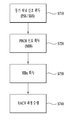
- FIG. 13 is a diagram for describing a method of repeatedly transmitting a PBCH to an MTC terminal by a base station.
- the base station may repeatedly transmit the PBCH encoding bit block PBCH (0) to the MTC terminal in the legacy PBCH region.
- the legacy PBCH region is allocated over 4 OFDM symbols and subframes corresponding to 6RB of the center frequency in the second slot slot 1 of the first subframe SF # 0 belonging to each frame.
- the PBCH encoded bit block transmitted in the legacy PBCH region and the PBCH encoded bit block transmitted in the other region are different from each other.
- PBCH (0) which is a PBCH encoding bit block
- the base station transmits PBCH (1) and PBCH in other regions.
- (2) or PBCH (3) can be repeatedly transmitted.
- the MTC terminal is allocated only the center 6RB in the frequency domain. That is, the area where the base station transmits the PBCH to the MTC terminal may be limited to the center 6RB.
- the base station may repeatedly transmit the remaining PBCH encoded bit blocks in SF # 0 different from the SF # 0 to which the legacy PBCH transmission region is allocated.
- the PBCH 2 and / or the PBCH 3 may be repeatedly transmitted in SF # 1.
- the transmission order of PBCH encoded bit blocks transmitted in the legacy PBCH transmission region and PBCH encoded bit blocks repeatedly transmitted in the other region may be arbitrarily set.
- PBCH encoded bit blocks are transmitted in a certain order. For example, when PBCH (0) is transmitted in the legacy PBCH transmission region, PBCH (1), PBCH (2), and PBCH (3) may be sequentially and repeatedly transmitted in other regions.
- the PBCH transmission structure described with reference to FIG. 13 may be used in an environment in which legacy terminals and MTC terminals coexist.
- the PBCH transmitted in the legacy PBCH transmission region may decode both the legacy terminal and the MTC terminal
- the PBCH transmitted outside the legacy PBCH region may be configured to decode only the MTC terminal.
- the PBCH transmission structure described with reference to FIG. 13 may be used only for the MTC terminal.
- the PBCH for the MTC terminal may be repeatedly transmitted in the legacy PBCH transmission region. Since the PBCH for the MTC terminal may transmit less information than the PBCH for the legacy terminal, repeated transmission of the PBCH to the MTC terminal may be performed even in the legacy PBCH transmission region.
- the repeated transmission of the PBCH is OFDM symbols other than the OFDM symbols used for PDCCH transmission. It can be performed in.
- the MTC terminal since the MTC terminal cannot decode the legacy PDCCH, it cannot know information about an OFDM symbol used for transmission of the legacy PDCCH. Therefore, assuming that a certain number of OFDM symbols are used for PDCCH transmission, the MTC terminal preferably receives PBCH encoded bit blocks repeatedly transmitted.
- the MTC terminal assumes that the legacy PDCCH is transmitted in a predetermined number of OFDM symbols (eg, 3 OFDM symbols). Assuming that the PBCH is repeatedly transmitted from the fourth OFDM symbol, the PBCH can be decoded and received. In this case, it is preferable that the number of OFDM symbols used for legacy PDCCH transmission is a natural number of 4 or less.
- a control region to which a legacy PDCCH is allocated may be excluded from a region in which the PBCH is repeatedly transmitted. Can be. That is, the MTC terminal may assume that PBCH is not transmitted in a predetermined number of OFDM symbols considered as a control region, and may decode PBCH encoding bit blocks repeatedly transmitted in other data regions.
- the RE to which the CSI-RS can be transmitted according to the CSI-RS configuration it may be restricted so that repeated transmission of the PBCH is not performed.
- the CSI-RS configuration may assume a CSI-RS RE corresponding to a configuration commonly used for FDD and TDD.
- CSI-RS configuration indexes 0 to 19 of a general CP system are commonly used for FDD and TDD.
- the CSI-RS is transmitted in the 6th and 7th OFDM symbols in the first slot of SF, and the CSI-RS is transmitted in the 3rd and 4th or 6th and 7th OFDM symbols in the second slot.
- FIG. 14 is a diagram for describing a method of repeatedly transmitting an MTC PBCH to an MTC terminal.
- a base station may repeatedly transmit a first PBCH (eg, PBCH (0)), which is a PBCH encoding bit block, to a MTC terminal in a legacy PBCH transmission region of a first subframe (eg, SF # 0). (S1410).
- PBCH (0) a PBCH encoding bit block
- the base station may repeatedly transmit a second PBCH (eg, PBCH (1), PBCH (2) or PBCH (3)), which is a PBCH encoding bead block, in the MTC transmission region of the first subframe to the MTC terminal ( S1420).
- a second PBCH eg, PBCH (1), PBCH (2) or PBCH (3)
- PBCH (1), PBCH (2) or PBCH (3) which is a PBCH encoding bead block
- step S1420 the base station performs remaining PBCH encoding bit blocks in a second subframe different from the first subframe (for example, SF # 1).
- a second subframe different from the first subframe for example, SF # 1.
- PBCH (1), PBCH (2) or PBCH (3) may be repeatedly transmitted to the MTC terminal (S1430).
- the MTC transmission area may mean a transmission area allocated for the MTC terminal.
- the MTC transmission region may be configured of a specific subframe or the center 6RB of each subframe.
- Sections 1 to 5 described above may be applied to the method described in FIG. 14.
- the methods described in section 5 may be applied.
- the legacy PBCH transmission region and the MTC transmission region may be referred to.
- the control region and the RE to which the RS is transmitted may be configured not to transmit the PBCH. have.
- FIG. 15 is a means in which the methods described in FIGS. 1 to 14 may be implemented.
- a UE may operate as a transmitting end in uplink and a receiving end in downlink.
- an e-Node B eNB
- eNB e-Node B
- the terminal and the base station may include transmitters 1540 and 1550 and receivers 1550 and 1570 to control transmission and reception of information, data and / or messages, respectively.
- the antenna may include antennas 1500 and 1510 for transmitting and receiving messages.
- the terminal and the base station may each include a processor 1520 and 1530 for performing the above-described embodiments of the present invention, and memories 1580 and 1590 for temporarily or continuously storing the processing of the processor. Can be.
- Embodiments of the present invention can be performed using the components and functions of the above-described terminal and base station apparatus.
- the processor of the base station may control the transmitter to perform PBCH repetitive transmission.
- the processor of the base station may repeatedly transmit the PBCH to the MTC terminal in the same subframe and other subframes to which the legacy PBCH transmission region and the legacy PBCH transmission region belong to repeatedly transmit the MTC PBCH to the MTC terminal.
- the processor of the base station transmits the PBCH in the control regions in which the PDCCH is transmitted and in REs in which a reference signal (for example, cell-specific and / or UE-specific reference signals) are transmitted. It can be configured not to.
- the processor of the UE may decode the corresponding subframes and receive the PBCH assuming that the PBCH is not repeatedly transmitted in these restricted areas. Such operations may be performed by applying the embodiments of the present invention described in Sections 1 to 5.
- the transmitter and the receiver included in the terminal and the base station include a packet modulation and demodulation function, a high speed packet channel coding function, an orthogonal frequency division multiple access (OFDMA) packet scheduling, and a time division duplex (TDD) for data transmission. Packet scheduling and / or channel multiplexing may be performed.
- the terminal and base station of FIG. 15 may further include a low power radio frequency (RF) / intermediate frequency (IF) unit.
- RF radio frequency
- IF intermediate frequency
- the terminal is a personal digital assistant (PDA), a cellular phone, a personal communication service (PCS) phone, a GSM (Global System for Mobile) phone, a WCDMA (Wideband CDMA) phone, an MBS.
- PDA personal digital assistant
- PCS personal communication service
- GSM Global System for Mobile
- WCDMA Wideband CDMA
- MBS Multi Mode-Multi Band
- a smart phone is a terminal that combines the advantages of a mobile communication terminal and a personal portable terminal, and may mean a terminal incorporating data communication functions such as schedule management, fax transmission and reception, which are functions of a personal mobile terminal, in a mobile communication terminal.
- a multimode multiband terminal can be equipped with a multi-modem chip to operate in both portable Internet systems and other mobile communication systems (e.g., code division multiple access (CDMA) 2000 systems, wideband CDMA (WCDMA) systems, etc.). Speak the terminal.
- CDMA code division multiple access
- WCDMA wideband CDMA
- Embodiments of the invention may be implemented through various means.
- embodiments of the present invention may be implemented by hardware, firmware, software, or a combination thereof.
- the method according to embodiments of the present invention may include one or more application specific integrated circuits (ASICs), digital signal processors (DSPs), digital signal processing devices (DSPDs), programmable logic devices (PLDs). Field programmable gate arrays (FPGAs), processors, controllers, microcontrollers, microprocessors, and the like.
- ASICs application specific integrated circuits
- DSPs digital signal processors
- DSPDs digital signal processing devices
- PLDs programmable logic devices
- FPGAs Field programmable gate arrays
- processors controllers, microcontrollers, microprocessors, and the like.
- the method according to the embodiments of the present invention may be implemented in the form of a module, a procedure, or a function that performs the functions or operations described above.
- software code may be stored in the memory units 1580 and 1590 and driven by the processors 1520 and 1530.
- the memory unit may be located inside or outside the processor, and may exchange data with the processor by various known means.
- Embodiments of the present invention can be applied to various wireless access systems.
- various radio access systems include 3rd Generation Partnership Project (3GPP), 3GPP2 and / or IEEE 802.xx (Institute of Electrical and Electronic Engineers 802) systems.
- Embodiments of the present invention can be applied not only to the various radio access systems, but also to all technical fields to which the various radio access systems are applied.
Abstract
The present invention relates to a wireless access system supporting a machine-type communication (MTC), and particularly, provided are a method for repeatedly transmitting a physical broadcast channel (PBCH) for an MTC, and apparatuses for supporting same. The method for repeatedly transmitting a PBCH for an MTC terminal in a wireless access system supporting MTC according to one embodiment of the present invention may comprise the steps of: transmitting a first PBCH by means of a legacy PBCH transmission region of a first subframe; repeatedly transmitting a second PBCH from the first subframe; and repeatedly transmitting a third PBCH from a second subframe. Here, the present invention can be structured so that the second PBCH and third PBCH are not repeatedly transmitted in the control regions of the first subframe and second subframe.
Description
본 발명은 기계타입통신(MTC: Machine Type Communication)을 지원하는 무선 접속 시스템에 관한 것으로, 특히 MTC 단말에 대한 물리방송채널(PBCH: Physical Broadcast Channel)을 반복적으로 송수신하는 방법 및 장치에 관한 것이다.The present invention relates to a wireless access system supporting Machine Type Communication (MTC), and more particularly, to a method and apparatus for repeatedly transmitting and receiving a physical broadcast channel (PBCH) for an MTC terminal.
무선 접속 시스템이 음성이나 데이터 등과 같은 다양한 종류의 통신 서비스를 제공하기 위해 광범위하게 전개되고 있다. 일반적으로 무선 접속 시스템은 가용한 시스템 자원(대역폭, 전송 파워 등)을 공유하여 다중 사용자와의 통신을 지원할 수 있는 다중 접속(multiple access) 시스템이다. 다중 접속 시스템의 예들로는 CDMA(code division multiple access) 시스템, FDMA(frequency division multiple access) 시스템, TDMA(time division multiple access) 시스템, OFDMA(orthogonal frequency division multiple access) 시스템, SC-FDMA(single carrier frequency division multiple access) 시스템 등이 있다.Wireless access systems are widely deployed to provide various kinds of communication services such as voice and data. In general, a wireless access system is a multiple access system capable of supporting communication with multiple users by sharing available system resources (bandwidth, transmission power, etc.). Examples of multiple access systems include code division multiple access (CDMA) systems, frequency division multiple access (FDMA) systems, time division multiple access (TDMA) systems, orthogonal frequency division multiple access (OFDMA) systems, and single carrier frequency (SC-FDMA). division multiple access) system.
본 발명의 목적은 MTC 단말에 대한 PBCH를 구성하는 방법을 제공하는 것이다.An object of the present invention is to provide a method for configuring a PBCH for the MTC terminal.
본 발명의 다른 목적은 MTC 단말에 대한 PBCH를 통해 전송되는 제어정보를 반복적으로 전송하는 방법을 제공하는 것이다.Another object of the present invention is to provide a method for repeatedly transmitting control information transmitted through a PBCH for an MTC terminal.
본 발명의 또 다른 목적은 이러한 방법들을 지원하는 장치를 제공하는 것이다.Another object of the present invention is to provide an apparatus supporting these methods.
본 발명에서 이루고자 하는 기술적 목적들은 이상에서 언급한 사항들로 제한되지 않으며, 언급하지 않은 또 다른 기술적 과제들은 이하 설명할 본 발명의 실시예들로부터 본 발명이 속하는 기술분야에서 통상의 지식을 가진 자에 의해 고려될 수 있다.Technical objects to be achieved in the present invention are not limited to the above-mentioned matters, and other technical problems which are not mentioned are those skilled in the art from the embodiments of the present invention to be described below. Can be considered.
본 발명은 기계타입통신(MTC)을 지원하는 무선 접속 시스템에 관한 것으로, 특히 MTC 에 대해 물리방송채널(PBCH)을 반복적으로 전송하는 방법 및 이를 지원하는 장치들을 제공한다.The present invention relates to a radio access system supporting machine type communication (MTC), and more particularly, to a method of repeatedly transmitting a physical broadcast channel (PBCH) for an MTC and to provide apparatuses for supporting the same.
본 발명의 일 양태로서 기계타입통신(MTC)을 지원하는 무선접속시스템에서 MTC 단말을 위한 물리방송채널(PBCH)을 반복하여 전송하는 방법은, 제1서브프레임의 레가시 PBCH 전송 영역을 통해 제1PBCH를 전송하는 단계와 제1서브프레임에서 제2PBCH를 반복 전송하는 단계와 제2서브프레임에서 제3PBCH를 반복 전송하는 단계를 포함할 수 있다. 이때, 제1서브프레임 및 제2서브프레임의 제어 영역에서는 제2PBCH 및 제3PBCH의 반복 전송이 수행되지 않도록 구성될 수 있다.In one aspect of the present invention, a method of repeatedly transmitting a physical broadcast channel (PBCH) for an MTC terminal in a wireless access system supporting machine type communication (MTC) includes: a first PBCH through a legacy PBCH transmission region of a first subframe; And transmitting the second PBCH repeatedly in the first subframe and transmitting the third PBCH repeatedly in the second subframe. In this case, the control region of the first subframe and the second subframe may be configured such that repetitive transmission of the second PBCH and the third PBCH is not performed.
본 발명의 다른 양태로서 기계타입통신(MTC)을 지원하는 무선접속시스템에서 MTC 단말을 위한 물리방송채널(PBCH)을 반복하여 전송하는 기지국은 송신기 및 PBCH의 반복 전송을 지원하기 위한 프로세서를 포함할 수 있다. 이때, 프로세서는 송신기를 제어하여 제1서브프레임의 레가시 PBCH 전송 영역을 통해 제1PBCH를 전송하고; 제1서브프레임에서 제2PBCH를 반복 전송하고; 제2서브프레임에서 제3PBCH를 반복 전송하도록 구성될 수 있다. 또한, 제1서브프레임 및 제2서브프레임의 제어 영역에서는 제2PBCH 및 제3PBCH의 반복 전송이 수행되지 않도록 구성될 수 있다.In another aspect of the present invention, a base station for repeatedly transmitting a physical broadcast channel (PBCH) for an MTC terminal in a wireless access system supporting machine type communication (MTC) may include a transmitter and a processor for supporting repeated transmission of the PBCH. Can be. At this time, the processor controls the transmitter to transmit the first PBCH through the legacy PBCH transmission region of the first subframe; Repeatedly transmitting the second PBCH in the first subframe; It may be configured to repeatedly transmit the third PBCH in the second subframe. In addition, the control region of the first subframe and the second subframe may be configured such that repetitive transmission of the second PBCH and the third PBCH is not performed.
제어 영역은 제1서브프레임 및 제2서브프레임의 첫 번째 슬롯의 첫 번째 심볼부터 세 번째 또는 네 번째 심볼까지 할당될 수 있다.The control region may be allocated from the first symbol to the third or fourth symbol of the first slot of the first subframe and the second subframe.
제2서브프레임에서 참조 신호(RS)가 할당되는 자원 요소(RE)에는 제3PBCH가 할당되지 않도록 구성될 수 있다. 이때, RS는 채널 상태 정보 참조 신호(CSI-RS)이고, RE는 CSI-RS 구성 중 주파수분할다중화 방식(FDD) 및 시간분할다중화 방식(TDD)에 공통으로 사용되는 CSI-RS 구성에 매핑되는 CSI-RS가 할당되는 RE일 수 있다. 또한, 제2서브프레임에서 RE는 첫 번째 슬롯에서는 여섯 번째 및 일곱 번째 심볼에 할당되고, 두 번째 슬롯에서는 세 번째 및 네 번째 또는 여섯 번째 및 일곱 번째 심볼에 할당될 수 있다.The third PBCH may not be allocated to the resource element RE to which the reference signal RS is allocated in the second subframe. In this case, RS is a channel state information reference signal (CSI-RS), and RE is mapped to a CSI-RS configuration commonly used in a frequency division multiplexing scheme (FDD) and a time division multiplexing scheme (TDD) among CSI-RS configurations. It may be an RE to which the CSI-RS is allocated. In the second subframe, the RE may be allocated to the sixth and seventh symbols in the first slot and the third and fourth or the sixth and seventh symbols in the second slot.
제2PBCH는 제1서브프레임에서 MTC 단말을 위한 MTC 전송 영역을 통해 전송되고, 제3PBCH는 제2서브프레임에서 MTC 단말을 위한 MTC 전송 영역을 통해 전송될 수 있다.The second PBCH may be transmitted through the MTC transmission region for the MTC terminal in the first subframe, and the third PBCH may be transmitted through the MTC transmission region for the MTC terminal in the second subframe.
제1서브프레임 및 제2서브프레임은 연속된 서브프레임일 수 있다.The first subframe and the second subframe may be consecutive subframes.
상술한 본 발명의 양태들은 본 발명의 바람직한 실시예들 중 일부에 불과하며, 본원 발명의 기술적 특징들이 반영된 다양한 실시예들이 당해 기술분야의 통상적인 지식을 가진 자에 의해 이하 상술할 본 발명의 상세한 설명을 기반으로 도출되고 이해될 수 있다.The above-described aspects of the present invention are merely some of the preferred embodiments of the present invention, and various embodiments reflecting the technical features of the present invention will be described in detail by those skilled in the art. Based on the description, it can be derived and understood.
본 발명의 실시예들에 따르면 다음과 같은 효과가 있다.According to embodiments of the present invention has the following effects.
첫째, 열악한 환경에 위치한 MTC 단말들에게도 PBCH를 신뢰성 있게 전송할 수 있다.First, the PBCH can be reliably transmitted to MTC terminals located in poor environments.
둘째, MTC 단말에 대해서 반복 전송되는 새로운 MTC PBCH를 정의함으로써 레가시 단말에 영향을 미치지 않고 MTC 단말에 대한 시스템 정보를 효과적으로 전송할 수 있다.Second, by defining a new MTC PBCH repeatedly transmitted for the MTC terminal, it is possible to effectively transmit system information on the MTC terminal without affecting the legacy terminal.
셋째, 동일한 무선 프레임에서 동일한 PBCH 인코딩 비트 블록을 반복 전송함으로써, 위상차(phase difference) 값이 일정하게 되어 기지국 및/또는 MTC 단말이 주파수 트래킹 및/또는 주파수 오프셋 추정을 효율적이고도 정확히 수행할 수 있다.Third, by repeatedly transmitting the same PBCH encoded bit block in the same radio frame, a phase difference value is constant so that the base station and / or the MTC terminal can efficiently and accurately perform frequency tracking and / or frequency offset estimation. .
본 발명의 실시예들에서 얻을 수 있는 효과는 이상에서 언급한 효과들로 제한되지 않으며, 언급하지 않은 또 다른 효과들은 이하의 본 발명의 실시예들에 대한 기재로부터 본 발명이 속하는 기술분야에서 통상의 지식을 가진 자에게 명확하게 도출되고 이해될 수 있다. 즉, 본 발명을 실시함에 따른 의도하지 않은 효과들 역시 본 발명의 실시예들로부터 당해 기술분야의 통상의 지식을 가진 자에 의해 도출될 수 있다.Effects obtained in the embodiments of the present invention are not limited to the above-mentioned effects, and other effects not mentioned above are usually described in the technical field to which the present invention pertains from the description of the embodiments of the present invention. Can be clearly derived and understood by those who have That is, unintended effects of practicing the present invention may also be derived from those skilled in the art from the embodiments of the present invention.
본 발명에 관한 이해를 돕기 위해 상세한 설명의 일부로 포함되고, 첨부된 도면들은 본 발명에 대한 다양한 실시예들을 제공한다. 또한, 첨부된 도면들은 상세한 설명과 함께 본 발명의 실시 형태들을 설명하기 위해 사용된다.It is included as part of the detailed description to assist in understanding the present invention, and the accompanying drawings provide various embodiments of the present invention. In addition, the accompanying drawings are used to describe embodiments of the present invention in conjunction with the detailed description.
도 1은 물리 채널들 및 이들을 이용한 신호 전송 방법을 설명하기 위한 도면이다.1 is a diagram illustrating a physical channel and a signal transmission method using the same.
도 2는 무선 프레임의 구조의 일례를 나타내는 도면이다.2 is a diagram illustrating an example of a structure of a radio frame.
도 3는 하향링크 슬롯에 대한 자원 그리드(resource grid)를 예시한 도면이다.3 is a diagram illustrating a resource grid for a downlink slot.
도 4는 상향링크 서브 프레임의 구조의 일례를 나타내는 도면이다.4 is a diagram illustrating an example of a structure of an uplink subframe.
도 5는 하향링크 서브 프레임의 구조의 일례를 나타내는 도면이다.5 is a diagram illustrating an example of a structure of a downlink subframe.
도 6은 본 발명의 실시예들에서 사용되는 크로스 캐리어 스케줄링에 따른 LTE-A 시스템의 서브 프레임 구조를 나타낸다.6 illustrates a subframe structure of an LTE-A system according to cross carrier scheduling used in embodiments of the present invention.
도 7은 LTE/LTE-A 시스템에서 사용되는 초기 접속 과정의 일례를 나타내는 도면이다.7 is a diagram illustrating an example of an initial access procedure used in an LTE / LTE-A system.
도 8은 방송채널 신호를 전송하는 방법 중 하나를 나타내는 도면이다.8 is a diagram illustrating one method of transmitting a broadcast channel signal.
도 9는 CA 환경을 기반으로 동작하는 CoMP 시스템의 개념도이다.9 is a conceptual diagram of a CoMP system operating based on a CA environment.
도 10은 본 발명의 실시예들에서 사용될 수 있는 셀 특정 참조 신호(CRS: Cell specific Reference Signal)가 할당된 서브프레임의 일례를 나타내는 도면이다.FIG. 10 is a diagram illustrating an example of a subframe to which a cell specific reference signal (CRS) is allocated, which can be used in embodiments of the present invention.
도 11은 본 발명의 실시예들에서 사용될 수 있는 CSI-RS가 안테나 포트의 개수에 따라 할당된 서브프레임들의 일례를 나타내는 도면이다.FIG. 11 is a diagram illustrating an example of subframes in which CSI-RSs that can be used in embodiments of the present invention are allocated according to the number of antenna ports.
도 12는 LTE/LTE-A 시스템에서 사용되는 레가시 PDCCH(Legacy PDCCH), PDSCH 및 E-PDCCH가 다중화되는 일례를 나타내는 도면이다.FIG. 12 is a diagram illustrating an example in which legacy PDCCH, PDSCH, and E-PDCCH used in an LTE / LTE-A system are multiplexed.
도 13은 기지국에서 MTC 단말에게 PBCH를 반복 전송하는 방법을 설명하기 위한 도면이다.FIG. 13 is a diagram for describing a method of repeatedly transmitting a PBCH to an MTC terminal by a base station.
도 14는 MTC 단말에 MTC PBCH를 반복전송하는 방법을 설명하기 위한 도면이다.14 is a diagram for describing a method of repeatedly transmitting an MTC PBCH to an MTC terminal.
도 15에서 설명하는 장치는 도 1 내지 도 14에서 설명한 방법들이 구현될 수 있는 수단이다.The apparatus described in FIG. 15 is a means in which the methods described in FIGS. 1 to 14 may be implemented.
이하에서 상세히 설명하는 본 발명의 실시예들은 단말의 위치를 측정하기 위해 이종망 신호를 이용하는 방법 및 장치들을 제공한다.Embodiments of the present invention described in detail below provide methods and apparatuses using heterogeneous network signals to measure the position of a terminal.
이하의 실시예들은 본 발명의 구성요소들과 특징들을 소정 형태로 결합한 것들이다. 각 구성요소 또는 특징은 별도의 명시적 언급이 없는 한 선택적인 것으로 고려될 수 있다. 각 구성요소 또는 특징은 다른 구성요소나 특징과 결합되지 않은 형태로 실시될 수 있다. 또한, 일부 구성요소들 및/또는 특징들을 결합하여 본 발명의 실시예를 구성할 수도 있다. 본 발명의 실시예들에서 설명되는 동작들의 순서는 변경될 수 있다. 어느 실시예의 일부 구성이나 특징은 다른 실시예에 포함될 수 있고, 또는 다른 실시예의 대응하는 구성 또는 특징과 교체될 수 있다.The following embodiments combine the components and features of the present invention in a predetermined form. Each component or feature may be considered to be optional unless otherwise stated. Each component or feature may be embodied in a form that is not combined with other components or features. In addition, some components and / or features may be combined to form an embodiment of the present invention. The order of the operations described in the embodiments of the present invention may be changed. Some components or features of one embodiment may be included in another embodiment or may be replaced with corresponding components or features of another embodiment.
도면에 대한 설명에서, 본 발명의 요지를 흐릴 수 있는 절차 또는 단계 등은 기술하지 않았으며, 당업자의 수준에서 이해할 수 있을 정도의 절차 또는 단계는 또한 기술하지 아니하였다.In the description of the drawings, procedures or steps which may obscure the gist of the present invention are not described, and procedures or steps that can be understood by those skilled in the art are not described.
명세서 전체에서, 어떤 부분이 어떤 구성요소를 "포함(comprising 또는 including)"한다고 할 때, 이는 특별히 반대되는 기재가 없는 한 다른 구성요소를 제외하는 것이 아니라 다른 구성요소를 더 포함할 수 있는 것을 의미한다. 또한, 명세서에 기재된 "…부", "…기", "모듈" 등의 용어는 적어도 하나의 기능이나 동작을 처리하는 단위를 의미하며, 이는 하드웨어나 소프트웨어 또는 하드웨어 및 소프트웨어의 결합으로 구현될 수 있다. 또한, "일(a 또는 an)", "하나(one)", "그(the)" 및 유사 관련어는 본 발명을 기술하는 문맥에 있어서(특히, 이하의 청구항의 문맥에서) 본 명세서에 달리 지시되거나 문맥에 의해 분명하게 반박되지 않는 한, 단수 및 복수 모두를 포함하는 의미로 사용될 수 있다.Throughout the specification, when a part is said to "comprising" (or including) a component, this means that it may further include other components, except to exclude other components unless specifically stated otherwise. do. In addition, the terms “… unit”, “… unit”, “module”, etc. described in the specification mean a unit that processes at least one function or operation, which may be implemented by hardware or software or a combination of hardware and software. have. Also, "a or an", "one", "the", and the like are used differently in the context of describing the present invention (particularly in the context of the following claims). Unless otherwise indicated or clearly contradicted by context, it may be used in the sense including both the singular and the plural.
본 명세서에서 본 발명의 실시예들은 기지국과 이동국 간의 데이터 송수신 관계를 중심으로 설명되었다. 여기서, 기지국은 이동국과 직접적으로 통신을 수행하는 네트워크의 종단 노드(terminal node)로서의 의미가 있다. 본 문서에서 기지국에 의해 수행되는 것으로 설명된 특정 동작은 경우에 따라서는 기지국의 상위 노드(upper node)에 의해 수행될 수도 있다.In the present specification, embodiments of the present invention have been described based on data transmission / reception relations between a base station and a mobile station. Here, the base station is meant as a terminal node of a network that directly communicates with a mobile station. The specific operation described as performed by the base station in this document may be performed by an upper node of the base station in some cases.
즉, 기지국을 포함하는 다수의 네트워크 노드들(network nodes)로 이루어지는 네트워크에서 이동국과의 통신을 위해 수행되는 다양한 동작들은 기지국 또는 기지국 이외의 다른 네트워크 노드들에 의해 수행될 수 있다. 이때, '기지국'은 고정국(fixed station), Node B, eNode B(eNB), 발전된 기지국(ABS: Advanced Base Station) 또는 억세스 포인트(access point) 등의 용어에 의해 대체될 수 있다.That is, various operations performed for communication with a mobile station in a network consisting of a plurality of network nodes including a base station may be performed by the base station or network nodes other than the base station. In this case, the 'base station' may be replaced by terms such as a fixed station, a Node B, an eNode B (eNB), an advanced base station (ABS), or an access point.
또한, 본 발명의 실시예들에서 단말(Terminal)은 사용자 기기(UE: User Equipment), 이동국(MS: Mobile Station), 가입자 단말(SS: Subscriber Station), 이동 가입자 단말(MSS: Mobile Subscriber Station), 이동 단말(Mobile Terminal) 또는 발전된 이동단말(AMS: Advanced Mobile Station) 등의 용어로 대체될 수 있다.Further, in embodiments of the present invention, a terminal may be a user equipment (UE), a mobile station (MS), a subscriber station (SS), or a mobile subscriber station (MSS). It may be replaced with terms such as a mobile terminal or an advanced mobile station (AMS).
또한, 송신단은 데이터 서비스 또는 음성 서비스를 제공하는 고정 및/또는 이동 노드를 말하고, 수신단은 데이터 서비스 또는 음성 서비스를 수신하는 고정 및/또는 이동 노드를 의미한다. 따라서, 상향링크에서는 이동국이 송신단이 되고, 기지국이 수신단이 될 수 있다. 마찬가지로, 하향링크에서는 이동국이 수신단이 되고, 기지국이 송신단이 될 수 있다.Also, the transmitting end refers to a fixed and / or mobile node that provides a data service or a voice service, and the receiving end refers to a fixed and / or mobile node that receives a data service or a voice service. Therefore, in uplink, a mobile station may be a transmitting end and a base station may be a receiving end. Similarly, in downlink, a mobile station may be a receiving end and a base station may be a transmitting end.
본 발명의 실시예들은 무선 접속 시스템들인 IEEE 802.xx 시스템, 3GPP(3rd Generation Partnership Project) 시스템, 3GPP LTE 시스템 및 3GPP2 시스템 중 적어도 하나에 개시된 표준 문서들에 의해 뒷받침될 수 있으며, 특히, 본 발명의 실시예들은 3GPP TS 36.211, 3GPP TS 36.212, 3GPP TS 36.213, 3GPP TS 36.321 및 3GPP TS 36.331 문서들에 의해 뒷받침 될 수 있다. 즉, 본 발명의 실시예들 중 설명하지 않은 자명한 단계들 또는 부분들은 상기 문서들을 참조하여 설명될 수 있다. 또한, 본 문서에서 개시하고 있는 모든 용어들은 상기 표준 문서에 의해 설명될 수 있다.Embodiments of the present invention may be supported by standard documents disclosed in at least one of the IEEE 802.xx system, the 3rd Generation Partnership Project (3GPP) system, the 3GPP LTE system, and the 3GPP2 system, which are wireless access systems, and in particular, the present invention. Embodiments of the may be supported by 3GPP TS 36.211, 3GPP TS 36.212, 3GPP TS 36.213, 3GPP TS 36.321 and 3GPP TS 36.331 documents. That is, obvious steps or portions not described among the embodiments of the present invention may be described with reference to the above documents. In addition, all terms disclosed in the present document can be described by the above standard document.
이하, 본 발명에 따른 바람직한 실시 형태를 첨부된 도면을 참조하여 상세하게 설명한다. 첨부된 도면과 함께 이하에 개시될 상세한 설명은 본 발명의 예시적인 실시형태를 설명하고자 하는 것이며, 본 발명이 실시될 수 있는 유일한 실시형태를 나타내고자 하는 것이 아니다.Hereinafter, exemplary embodiments of the present invention will be described in detail with reference to the accompanying drawings. The detailed description, which will be given below with reference to the accompanying drawings, is intended to explain exemplary embodiments of the present invention and is not intended to represent the only embodiments in which the present invention may be practiced.
또한, 본 발명의 실시예들에서 사용되는 특정(特定) 용어들은 본 발명의 이해를 돕기 위해서 제공된 것이며, 이러한 특정 용어의 사용은 본 발명의 기술적 사상을 벗어나지 않는 범위에서 다른 형태로 변경될 수 있다.In addition, specific terms used in the embodiments of the present invention are provided to help the understanding of the present invention, and the use of the specific terms may be changed into other forms without departing from the technical spirit of the present invention. .
이하에서는 본 발명의 실시예들이 사용될 수 있는 무선 접속 시스템의 일례로 3GPP LTE/LTE-A 시스템에 대해서 설명한다.Hereinafter, a 3GPP LTE / LTE-A system will be described as an example of a wireless access system in which embodiments of the present invention can be used.
이하의 기술은 CDMA(code division multiple access), FDMA(frequency division multiple access), TDMA(time division multiple access), OFDMA(orthogonal frequency division multiple access), SC-FDMA(single carrier frequency division multiple access) 등과 같은 다양한 무선 접속 시스템에 적용될 수 있다.The following techniques include code division multiple access (CDMA), frequency division multiple access (FDMA), time division multiple access (TDMA), orthogonal frequency division multiple access (OFDMA), single carrier frequency division multiple access (SC-FDMA), and the like. It can be applied to various radio access systems.
CDMA는 UTRA(Universal Terrestrial Radio Access)나 CDMA2000과 같은 무선 기술(radio technology)로 구현될 수 있다. TDMA는 GSM(Global System for Mobile communications)/GPRS(General Packet Radio Service)/EDGE(Enhanced Data Rates for GSM Evolution)와 같은 무선 기술로 구현될 수 있다. OFDMA는 IEEE 802.11 (Wi-Fi), IEEE 802.16 (WiMAX), IEEE 802-20, E-UTRA(Evolved UTRA) 등과 같은 무선 기술로 구현될 수 있다.CDMA may be implemented with a radio technology such as Universal Terrestrial Radio Access (UTRA) or CDMA2000. TDMA may be implemented with wireless technologies such as Global System for Mobile communications (GSM) / General Packet Radio Service (GPRS) / Enhanced Data Rates for GSM Evolution (EDGE). OFDMA may be implemented in a wireless technology such as IEEE 802.11 (Wi-Fi), IEEE 802.16 (WiMAX), IEEE 802-20, Evolved UTRA (E-UTRA).
UTRA는 UMTS(Universal Mobile Telecommunications System)의 일부이다. 3GPP LTE(Long Term Evolution)은 E-UTRA를 사용하는 E-UMTS(Evolved UMTS)의 일부로써, 하향링크에서 OFDMA를 채용하고 상향링크에서 SC-FDMA를 채용한다. LTE-A(Advanced) 시스템은 3GPP LTE 시스템이 개량된 시스템이다. 본 발명의 기술적 특징에 대한 설명을 명확하게 하기 위해, 본 발명의 실시예들을 3GPP LTE/LTE-A 시스템을 위주로 기술하지만 IEEE 802.16e/m 시스템 등에도 적용될 수 있다.UTRA is part of the Universal Mobile Telecommunications System (UMTS). 3GPP Long Term Evolution (LTE) is part of an Evolved UMTS (E-UMTS) using E-UTRA, and employs OFDMA in downlink and SC-FDMA in uplink. The LTE-A (Advanced) system is an improved system of the 3GPP LTE system. In order to clarify the description of the technical features of the present invention, embodiments of the present invention will be described based on the 3GPP LTE / LTE-A system, but can also be applied to IEEE 802.16e / m system and the like.
1. 3GPP LTE/LTE_A 시스템1.3GPP LTE / LTE_A System
무선 접속 시스템에서 단말은 하향링크(DL: Downlink)를 통해 기지국으로부터 정보를 수신하고, 상향링크(UL: Uplink)를 통해 기지국으로 정보를 전송한다. 기지국과 단말이 송수신하는 정보는 일반 데이터 정보 및 다양한 제어 정보를 포함하고, 이들이 송수신 하는 정보의 종류/용도에 따라 다양한 물리 채널이 존재한다.In a wireless access system, a terminal receives information from a base station through downlink (DL) and transmits information to the base station through uplink (UL). The information transmitted and received by the base station and the terminal includes general data information and various control information, and various physical channels exist according to the type / use of the information they transmit and receive.
1.1 시스템 일반1.1 System General
도 1은 본 발명의 실시예들에서 사용될 수 있는 물리 채널들 및 이들을 이용한 신호 전송 방법을 설명하기 위한 도면이다.1 is a diagram for explaining physical channels that can be used in embodiments of the present invention and a signal transmission method using the same.
전원이 꺼진 상태에서 다시 전원이 켜지거나, 새로이 셀에 진입한 단말은 S11 단계에서 기지국과 동기를 맞추는 등의 초기 셀 탐색 (Initial cell search) 작업을 수행한다. 이를 위해 단말은 기지국으로부터 주동기 채널 (P-SCH: Primary Synchronization Channel) 및 부동기 채널 (S-SCH: Secondary Synchronization Channel)을 수신하여 기지국과 동기를 맞추고, 셀 ID 등의 정보를 획득한다.When the power is turned off again or a new cell enters the cell, the initial cell search operation such as synchronizing with the base station is performed in step S11. To this end, the UE receives a Primary Synchronization Channel (P-SCH) and a Secondary Synchronization Channel (S-SCH) from the base station, synchronizes with the base station, and obtains information such as a cell ID.
그 후, 단말은 기지국으로부터 물리방송채널 (PBCH: Physical Broadcast Channel) 신호를 수신하여 셀 내 방송 정보를 획득할 수 있다.Thereafter, the terminal may receive a physical broadcast channel (PBCH) signal from the base station to obtain broadcast information in a cell.
한편, 단말은 초기 셀 탐색 단계에서 하향링크 참조 신호 (DL RS: Downlink Reference Signal)를 수신하여 하향링크 채널 상태를 확인할 수 있다.On the other hand, the terminal may receive a downlink reference signal (DL RS) in the initial cell search step to confirm the downlink channel state.
초기 셀 탐색을 마친 단말은 S12 단계에서 물리하향링크제어채널 (PDCCH: Physical Downlink Control Channel) 및 물리하향링크제어채널 정보에 따른 물리하향링크공유 채널 (PDSCH: Physical Downlink Control Channel)을 수신하여 조금 더 구체적인 시스템 정보를 획득할 수 있다.After completing the initial cell search, the UE receives a physical downlink control channel (PDCCH) and a physical downlink control channel (PDSCH) according to the physical downlink control channel information in step S12. Specific system information can be obtained.
이후, 단말은 기지국에 접속을 완료하기 위해 이후 단계 S13 내지 단계 S16과 같은 임의 접속 과정 (Random Access Procedure)을 수행할 수 있다. 이를 위해 단말은 물리임의접속채널 (PRACH: Physical Random Access Channel)을 통해 프리앰블 (preamble)을 전송하고(S13), 물리하향링크제어채널 및 이에 대응하는 물리하향링크공유 채널을 통해 프리앰블에 대한 응답 메시지를 수신할 수 있다(S14). 경쟁 기반 임의 접속의 경우, 단말은 추가적인 물리임의접속채널 신호의 전송(S15) 및 물리하향링크제어채널 신호 및 이에 대응하는 물리하향링크공유 채널 신호의 수신(S16)과 같은 충돌해결절차 (Contention Resolution Procedure)를 수행할 수 있다.Subsequently, the terminal may perform a random access procedure as in steps S13 to S16 to complete the access to the base station. To this end, the UE transmits a preamble through a physical random access channel (PRACH) (S13), a response message to the preamble through a physical downlink control channel and a corresponding physical downlink shared channel. Can be received (S14). In case of contention-based random access, the UE may perform contention resolution such as transmitting an additional physical random access channel signal (S15) and receiving a physical downlink control channel signal and a corresponding physical downlink shared channel signal (S16). Procedure).
상술한 바와 같은 절차를 수행한 단말은 이후 일반적인 상/하향링크 신호 전송 절차로서 물리하향링크제어채널 신호 및/또는 물리하향링크공유채널 신호의 수신(S17) 및 물리상향링크공유채널 (PUSCH: Physical Uplink Shared Channel) 신호 및/또는 물리상향링크제어채널 (PUCCH: Physical Uplink Control Channel) 신호의 전송(S18)을 수행할 수 있다.After performing the above-described procedure, the UE subsequently receives a physical downlink control channel signal and / or a physical downlink shared channel signal (S17) and a physical uplink shared channel (PUSCH) as a general uplink / downlink signal transmission procedure. A transmission (Uplink Shared Channel) signal and / or a Physical Uplink Control Channel (PUCCH) signal may be transmitted (S18).
단말이 기지국으로 전송하는 제어정보를 통칭하여 상향링크 제어정보(UCI: Uplink Control Information)라고 지칭한다. UCI는 HARQ-ACK/NACK (Hybrid Automatic Repeat and reQuest Acknowledgement/Negative-ACK), SR (Scheduling Request), CQI (Channel Quality Indication), PMI (Precoding Matrix Indication), RI (Rank Indication) 정보 등을 포함한다.The control information transmitted from the terminal to the base station is collectively referred to as uplink control information (UCI). UCI includes Hybrid Automatic Repeat and reQuest Acknowledgement / Negative-ACK (HARQ-ACK / NACK), Scheduling Request (SR), Channel Quality Indication (CQI), Precoding Matrix Indication (PMI), and Rank Indication (RI). .
LTE 시스템에서 UCI는 일반적으로 PUCCH를 통해 주기적으로 전송되지만, 제어정보와 트래픽 데이터가 동시에 전송되어야 할 경우 PUSCH를 통해 전송될 수 있다. 또한, 네트워크의 요청/지시에 의해 PUSCH를 통해 UCI를 비주기적으로 전송할 수 있다.In the LTE system, UCI is generally transmitted periodically through the PUCCH, but may be transmitted through the PUSCH when control information and traffic data should be transmitted at the same time. In addition, the UCI may be aperiodically transmitted through the PUSCH by the request / instruction of the network.
도 2는 본 발명의 실시예들에서 사용되는 무선 프레임의 구조를 나타낸다.2 shows a structure of a radio frame used in embodiments of the present invention.
도 2(a)는 타입 1 프레임 구조(frame structure type 1)를 나타낸다. 타입 1 프레임 구조는 전이중(full duplex) FDD(Frequency Division Duplex) 시스템과 반이중(half duplex) FDD 시스템 모두에 적용될 수 있다.2 (a) shows a frame structure type 1. The type 1 frame structure can be applied to both full duplex Frequency Division Duplex (FDD) systems and half duplex FDD systems.
하나의 무선 프레임(radio frame)은 Tf = 307200*Ts = 10ms의 길이를 가지고, Tslot = 15360*Ts = 0.5ms의 균등한 길이를 가지며 0부터 19의 인덱스가 부여된 20개의 슬롯으로 구성된다. 하나의 서브프레임은 2개의 연속된 슬롯으로 정의되며, i 번째 서브프레임은 2i 와 2i+1에 해당하는 슬롯으로 구성된다. 즉, 무선 프레임(radio frame)은 10개의 서브프레임(subframe)으로 구성된다. 하나의 서브프레임을 전송하는 데 걸리는 시간을 TTI(transmission time interval)이라 한다. 여기서, Ts 는 샘플링 시간을 나타내고, Ts=1/(15kHz×2048)=3.2552×10-8(약 33ns)로 표시된다. 슬롯은 시간 영역에서 복수의 OFDM 심볼 또는 SC-FDMA 심볼을 포함하고, 주파수 영역에서 복수의 자원블록(Resource Block)을 포함한다.One radio frame has a length of T f = 307 200 * T s = 10 ms, an equal length of T slot = 15360 * T s = 0.5 ms, and 20 slots indexed from 0 to 19 It consists of. One subframe is defined as two consecutive slots, and the i-th subframe includes slots corresponding to 2i and 2i + 1. That is, a radio frame consists of 10 subframes. The time taken to transmit one subframe is called a transmission time interval (TTI). Here, T s represents a sampling time and is represented by T s = 1 / (15 kHz x 2048) = 3.2552 x 10 -8 (about 33 ns). The slot includes a plurality of OFDM symbols or SC-FDMA symbols in the time domain and a plurality of resource blocks in the frequency domain.
하나의 슬롯은 시간 영역에서 복수의 OFDM(orthogonal frequency division multiplexing) 심볼을 포함한다. 3GPP LTE는 하향링크에서 OFDMA를 사용하므로 OFDM 심볼은 하나의 심볼 구간(symbol period)을 표현하기 위한 것이다. OFDM 심볼은 하나의 SC-FDMA 심볼 또는 심볼 구간이라고 할 수 있다. 자원 블록(resource block)은 자원 할당 단위이고, 하나의 슬롯에서 복수의 연속적인 부반송파(subcarrier)를 포함한다.One slot includes a plurality of orthogonal frequency division multiplexing (OFDM) symbols in the time domain. Since 3GPP LTE uses OFDMA in downlink, the OFDM symbol is for representing one symbol period. The OFDM symbol may be referred to as one SC-FDMA symbol or symbol period. A resource block is a resource allocation unit and includes a plurality of consecutive subcarriers in one slot.
전이중 FDD 시스템에서는 각 10ms 구간 동안 10개의 서브프레임은 하향링크 전송과 상향링크 전송을 위해 동시에 이용될 수 있다. 이때, 상향링크와 하향링크 전송은 주파수 영역에서 분리된다. 반면, 반이중 FDD 시스템의 경우 단말은 전송과 수신을 동시에 할 수 없다.In a full-duplex FDD system, 10 subframes may be used simultaneously for downlink transmission and uplink transmission during each 10ms period. At this time, uplink and downlink transmission are separated in the frequency domain. On the other hand, in the case of a half-duplex FDD system, the terminal cannot transmit and receive at the same time.
상술한 무선 프레임의 구조는 하나의 예시에 불과하며, 무선 프레임에 포함되는 서브 프레임의 수 또는 서브 프레임에 포함되는 슬롯의 수, 슬롯에 포함되는 OFDM 심볼의 수는 다양하게 변경될 수 있다.The structure of the radio frame described above is just one example, and the number of subframes included in the radio frame, the number of slots included in the subframe, and the number of OFDM symbols included in the slot may be variously changed.
도 2(b)는 타입 2 프레임 구조(frame structure type 2)를 나타낸다. 타입 2 프레임 구조는 TDD 시스템에 적용된다. 하나의 무선 프레임(radio frame)은 Tf = 307200*Ts = 10ms의 길이를 가지며, 153600*Ts = 5ms 길이를 가지는 2개의 하프프레임(half-frame)으로 구성된다. 각 하프프레임은 30720*Ts = 1ms의 길이를 가지는 5개의 서브프레임으로 구성된다. i 번째 서브프레임은 2i 와 2i+1에 해당하는 각 Tslot = 15360*Ts = 0.5ms의 길이를 가지는 2개의 슬롯으로 구성된다. 여기에서, Ts 는 샘플링 시간을 나타내고, Ts=1/(15kHz×2048)=3.2552×10-8(약 33ns)로 표시된다.2 (b) shows a frame structure type 2. Type 2 frame structure is applied to the TDD system. One radio frame has a length of T f = 307 200 * T s = 10 ms and consists of two half-frames having a length of 153600 * T s = 5 ms. Each half frame consists of five subframes having a length of 30720 * T s = 1 ms. The i-th subframe consists of two slots having a length of T slot = 15360 * T s = 0.5 ms corresponding to 2 i and 2 i + 1 . Here, T s represents a sampling time and is represented by T s = 1 / (15 kHz x 2048) = 3.2552 x 10 -8 (about 33 ns).
타입 2 프레임에는 DwPTS(Downlink Pilot Time Slot), 보호구간(GP: Guard Period), UpPTS(Uplink Pilot Time Slot)인 3가지의 필드로 구성되는 특별 서브프레임을 포함한다. 여기서, DwPTS는 단말에서의 초기 셀 탐색, 동기화 또는 채널 추정에 사용된다. UpPTS는 기지국에서의 채널 추정과 단말의 상향 전송 동기를 맞추는 데 사용된다. 보호구간은 상향링크와 하향링크 사이에 하향링크 신호의 다중경로 지연으로 인해 상향링크에서 생기는 간섭을 제거하기 위한 구간이다.The type 2 frame includes a special subframe consisting of three fields: a downlink pilot time slot (DwPTS), a guard period (GP), and an uplink pilot time slot (UpPTS). Here, the DwPTS is used for initial cell search, synchronization or channel estimation in the terminal. UpPTS is used for channel estimation at the base station and synchronization of uplink transmission of the terminal. The guard period is a period for removing interference generated in the uplink due to the multipath delay of the downlink signal between the uplink and the downlink.
다음 표 1는 특별 프레임의 구성(DwPTS/GP/UpPTS의 길이)을 나타낸다.Table 1 below shows the structure of the special frame (length of DwPTS / GP / UpPTS).

도 3은 본 발명의 실시예들에서 사용될 수 있는 하향링크 슬롯에 대한 자원 그리드(resource grid)를 예시한 도면이다.3 is a diagram illustrating a resource grid for a downlink slot that can be used in embodiments of the present invention.
도 3을 참조하면, 하나의 하향링크 슬롯은 시간 영역에서 복수의 OFDM 심볼을 포함한다. 여기서, 하나의 하향링크 슬롯은 7개의 OFDM 심볼을 포함하고, 하나의 자원 블록은 주파수 영역에서 12개의 부 반송파를 포함하는 것을 예시적으로 기술하나, 이에 한정되는 것은 아니다.Referring to FIG. 3, one downlink slot includes a plurality of OFDM symbols in the time domain. Here, one downlink slot includes seven OFDM symbols, and one resource block includes 12 subcarriers in a frequency domain, but is not limited thereto.
자원 그리드 상에서 각 요소(element)를 자원 요소(resource element)하고, 하나의 자원 블록은 12 × 7 개의 자원 요소를 포함한다. 하향링크 슬롯에 포함되는 자원 블록들의 수 NDL은 하향링크 전송 대역폭(bandwidth)에 종속한다. 상향링크 슬롯의 구조는 하향링크 슬롯의 구조와 동일할 수 있다.Each element on the resource grid is a resource element, and one resource block includes 12 × 7 resource elements. The number N DL of resource blocks included in the downlink slot depends on the downlink transmission bandwidth. The structure of the uplink slot may be the same as the structure of the downlink slot.
도 4는 본 발명의 실시예들에서 사용될 수 있는 상향링크 서브 프레임의 구조를 나타낸다.4 shows a structure of an uplink subframe that can be used in embodiments of the present invention.
도 4를 참조하면, 상향링크 서브 프레임은 주파수 영역에서 제어 영역과 데이터 영역으로 나눌 수 있다. 제어 영역에는 상향링크 제어 정보를 나르는 PUCCH가 할당된다. 데이터 영역은 사용자 데이터를 나르는 PUSCH가 할당된다. 단일 반송파 특성을 유지하기 위해 하나의 단말은 PUCCH와 PUSCH를 동시에 전송하지 않는다. 하나의 단말에 대한 PUCCH에는 서브 프레임 내에 RB 쌍이 할당된다. RB 쌍에 속하는 RB들은 2개의 슬롯들의 각각에서 서로 다른 부 반송파를 차지한다. 이러한 PUCCH에 할당된 RB 쌍은 슬롯 경계(slot boundary)에서 주파수 도약(frequency hopping)된다고 한다.Referring to FIG. 4, an uplink subframe may be divided into a control region and a data region in the frequency domain. The control region is allocated a PUCCH carrying uplink control information. In the data area, a PUSCH carrying user data is allocated. In order to maintain a single carrier characteristic, one UE does not simultaneously transmit a PUCCH and a PUSCH. The PUCCH for one UE is allocated an RB pair in a subframe. RBs belonging to the RB pair occupy different subcarriers in each of the two slots. The RB pair assigned to this PUCCH is said to be frequency hopping at the slot boundary.
도 5는 본 발명의 실시예들에서 사용될 수 있는 하향링크 서브 프레임의 구조를 나타낸다.5 shows a structure of a downlink subframe that can be used in embodiments of the present invention.
도 5를 참조하면, 서브 프레임내의 첫번째 슬롯에서 OFDM 심볼 인덱스 0부터 최대 3개의 OFDM 심볼들이 제어 채널들이 할당되는 제어 영역(control region)이고, 나머지 OFDM 심볼들은 PDSCH이 할당되는 데이터 영역(data region)이다. 3GPP LTE에서 사용되는 하향링크 제어 채널의 일례로 PCFICH(Physical Control Format Indicator Channel), PDCCH, PHICH(Physical Hybrid-ARQ Indicator Channel) 등이 있다.Referring to FIG. 5, up to three OFDM symbols from the OFDM symbol index 0 in the first slot in the subframe are control regions to which control channels are allocated, and the remaining OFDM symbols are data regions to which the PDSCH is allocated. to be. One example of a downlink control channel used in 3GPP LTE includes a Physical Control Format Indicator Channel (PCFICH), a PDCCH, and a Physical Hybrid-ARQ Indicator Channel (PHICH).
PCFICH는 서브 프레임의 첫 번째 OFDM 심볼에서 전송되고, 서브 프레임 내에 제어 채널들의 전송을 위하여 사용되는 OFDM 심볼들의 수(즉, 제어 영역의 크기)에 관한 정보를 나른다. PHICH는 상향 링크에 대한 응답 채널이고, HARQ(Hybrid Automatic Repeat Request)에 대한 ACK(Acknowledgement)/NACK(Negative-Acknowledgement) 신호를 나른다. PDCCH를 통해 전송되는 제어 정보를 하향링크 제어정보(DCI: downlink control information)라고 한다. 하향링크 제어정보는 상향링크 자원 할당 정보, 하향링크 자원 할당 정보 또는 임의의 단말 그룹에 대한 상향링크 전송(Tx) 파워 제어 명령을 포함한다.The PCFICH is transmitted in the first OFDM symbol of a subframe and carries information about the number of OFDM symbols (ie, the size of the control region) used for transmission of control channels within the subframe. The PHICH is a response channel for the uplink and carries an ACK (Acknowledgement) / NACK (Negative-Acknowledgement) signal for a hybrid automatic repeat request (HARQ). Control information transmitted through the PDCCH is called downlink control information (DCI). The downlink control information includes uplink resource allocation information, downlink resource allocation information or an uplink transmission (Tx) power control command for a certain terminal group.
2. 캐리어 병합(CA: Carrier Aggregation) 환경 2. Carrier Aggregation (CA) Environment
2.1 CA 일반2.1 CA General
3GPP LTE(3rd Generation Partnership Project Long Term Evolution; Rel-8 또는 Rel-9) 시스템(이하, LTE 시스템)은 단일 컴포넌트 캐리어(CC: Component Carrier)를 여러 대역으로 분할하여 사용하는 다중 반송파 변조(MCM: Multi-Carrier Modulation) 방식을 사용한다. 그러나, 3GPP LTE-Advanced 시스템(이하, LTE-A 시스템) 에서는 LTE 시스템보다 광대역의 시스템 대역폭을 지원하기 위해서 하나 이상의 컴포넌트 캐리어를 결합하여 사용하는 캐리어 병합(CA: Carrier Aggregation)과 같은 방법을 사용할 수 있다. 캐리어 병합은 반송파 집성, 반송파 정합, 멀티 컴포넌트 캐리어 환경(Multi-CC) 또는 멀티캐리어 환경이라는 말로 대체될 수 있다.3GPP LTE (3rd Generation Partnership Project Long Term Evolution (Rel-8 or Rel-9) system (hereinafter referred to as LTE system) is a multi-carrier modulation (MCM) that divides a single component carrier (CC) into multiple bands. Multi-Carrier Modulation) is used. However, in the 3GPP LTE-Advanced system (hereinafter, LTE-A system), a method such as Carrier Aggregation (CA) may be used in which one or more component carriers are combined to support a wider system bandwidth than the LTE system. have. Carrier aggregation may be replaced with the words carrier aggregation, carrier matching, multi-component carrier environment (Multi-CC) or multicarrier environment.
본 발명에서 멀티 캐리어는 캐리어의 병합(또는, 반송파 집성)을 의미하며, 이때 캐리어의 병합은 인접한(contiguous) 캐리어 간의 병합뿐 아니라 비 인접한(non-contiguous) 캐리어 간의 병합을 모두 의미한다. 또한, 하향링크와 상향링크 간에 집성되는 컴포넌트 캐리어들의 수는 다르게 설정될 수 있다. 하향링크 컴포넌트 캐리어(이하, 'DL CC'라 한다) 수와 상향링크 컴포넌트 캐리어(이하, 'UL CC'라 한다) 수가 동일한 경우를 대칭적(symmetric) 병합이라고 하고, 그 수가 다른 경우를 비대칭적(asymmetric) 병합이라고 한다. 이와 같은 캐리어 병합은 반송파 집성, 대역폭 집성(bandwidth aggregation), 스펙트럼 집성(spectrum aggregation) 등과 같은 용어와 혼용되어 사용될 수 있다.In the present invention, the multi-carrier means the aggregation of carriers (or carrier aggregation), wherein the aggregation of carriers means not only merging between contiguous carriers but also merging between non-contiguous carriers. In addition, the number of component carriers aggregated between downlink and uplink may be set differently. The case where the number of downlink component carriers (hereinafter referred to as 'DL CC') and the number of uplink component carriers (hereinafter referred to as 'UL CC') is the same is called symmetric merging. This is called asymmetric merging. Such carrier aggregation may be used interchangeably with terms such as carrier aggregation, bandwidth aggregation, spectrum aggregation, and the like.
두 개 이상의 컴포넌트 캐리어가 결합되어 구성되는 캐리어 병합은 LTE-A 시스템에서는 100MHz 대역폭까지 지원하는 것을 목표로 한다. 목표 대역보다 작은 대역폭을 가지는 1개 이상의 캐리어를 결합할 때, 결합하는 캐리어의 대역폭은 기존 IMT 시스템과의 호환성(backward compatibility) 유지를 위해서 기존 시스템에서 사용하는 대역폭으로 제한할 수 있다.Carrier aggregation, in which two or more component carriers are combined, aims to support up to 100 MHz bandwidth in an LTE-A system. When combining one or more carriers having a bandwidth smaller than the target band, the bandwidth of the combining carrier may be limited to the bandwidth used by the existing system to maintain backward compatibility with the existing IMT system.
예를 들어서 기존의 3GPP LTE 시스템에서는 {1.4, 3, 5, 10, 15, 20}MHz 대역폭을 지원하며, 3GPP LTE-advanced 시스템(즉, LTE-A)에서는 기존 시스템과의 호환을 위해 상기의 대역폭들만을 이용하여 20MHz보다 큰 대역폭을 지원하도록 할 수 있다. 또한, 본 발명에서 사용되는 캐리어 병합 시스템은 기존 시스템에서 사용하는 대역폭과 상관없이 새로운 대역폭을 정의하여 캐리어 병합을 지원하도록 할 수도 있다.For example, the existing 3GPP LTE system supports {1.4, 3, 5, 10, 15, 20} MHz bandwidth, and the 3GPP LTE-advanced system (i.e., LTE-A) supports the above for compatibility with the existing system. Only bandwidths can be used to support bandwidths greater than 20 MHz. In addition, the carrier aggregation system used in the present invention may support carrier aggregation by defining a new bandwidth regardless of the bandwidth used in the existing system.
또한, 위와 같은 캐리어 병합은 인트라-밴드 CA(Intra-band CA) 및 인터-밴드 CA(Inter-band CA)로 구분될 수 있다. 인트라-밴드 캐리어 병합이란, 다수의 DL CC 및/또는 UL CC들이 주파수상에서 인접하거나 근접하여 위치하는 것을 의미한다. 다시 말해, DL CC 및/또는 UL CC들의 캐리어 주파수가 동일한 밴드 내에 위치하는 것을 의미할 수 있다. 반면, 주파수 영역에서 멀리 떨어져 있는 환경을 인터-밴드 CA(Inter-Band CA)라고 부를 수 있다. 다시 말해, 다수의 DL CC 및/또는 UL CC들의 캐리어 주파수가 서로 다른 밴드들에 위치하는 것을 의미할 수 있다. 이와 같은 경우, 단말은 캐리어 병합 환경에서의 통신을 수행하기 위해서 복수의 RF(radio frequency)단을 사용할 수도 있다.In addition, the carrier aggregation may be divided into an intra-band CA and an inter-band CA. Intra-band carrier merging means that a plurality of DL CCs and / or UL CCs are located adjacent to or in proximity to frequency. In other words, it may mean that the carrier frequencies of the DL CCs and / or UL CCs are located in the same band. On the other hand, an environment far from the frequency domain may be referred to as an inter-band CA. In other words, it may mean that the carrier frequencies of the plurality of DL CCs and / or UL CCs are located in different bands. In this case, the terminal may use a plurality of radio frequency (RF) terminals to perform communication in a carrier aggregation environment.
LTE-A 시스템은 무선 자원을 관리하기 위해 셀(cell)의 개념을 사용한다. 상술한 캐리어 병합 환경은 다중 셀(multiple cells) 환경으로 일컬을 수 있다. 셀은 하향링크 자원(DL CC)과 상향링크 자원(UL CC) 한 쌍의 조합으로 정의되나, 상향링크 자원은 필수 요소는 아니다. 따라서, 셀은 하향링크 자원 단독, 또는 하향링크 자원과 상향링크 자원으로 구성될 수 있다.The LTE-A system uses the concept of a cell to manage radio resources. The carrier aggregation environment described above may be referred to as a multiple cell environment. A cell is defined as a combination of a downlink resource (DL CC) and an uplink resource (UL CC), but the uplink resource is not an essential element. Accordingly, the cell may be configured with only downlink resources or with downlink resources and uplink resources.
예를 들어, 특정 단말이 단 하나의 설정된 서빙 셀(configured serving cell)을 가지는 경우 1개의 DL CC와 1개의 UL CC를 가질 수 있다. 그러나, 특정 단말이 2개 이상의 설정된 서빙 셀을 가지는 경우에는 셀의 수만큼의 DL CC를 가지며 UL CC의 수는 그와 같거나 그보다 작을 수 있다. 또는, 그 반대로 DL CC와 UL CC가 구성될 수도 있다. 즉, 특정 단말이 다수의 설정된 서빙 셀을 가지는 경우 DL CC의 수보다 UL CC가 더 많은 캐리어 병합 환경도 지원될 수 있다.For example, when a specific UE has only one configured serving cell, it may have one DL CC and one UL CC. However, when a specific terminal has two or more configured serving cells, it may have as many DL CCs as the number of cells and the number of UL CCs may be the same or smaller than that. Alternatively, the DL CC and the UL CC may be configured on the contrary. That is, when a specific UE has a plurality of configured serving cells, a carrier aggregation environment in which a UL CC has more than the number of DL CCs may be supported.
또한, 캐리어 결합(CA)은 각각 캐리어 주파수(셀의 중심 주파수)가 서로 다른 둘 이상의 셀들의 병합으로 이해될 수 있다. 캐리어 결합에서 말하는 '셀(Cell)'은 주파수 관점에서 설명되는 것으로, 일반적으로 사용되는 기지국이 커버하는 지리적 영역으로서의 '셀'과는 구분되어야 한다. 이하, 상술한 인트라-밴드 캐리어 병합을 인트라-밴드 다중 셀이라고 지칭하며, 인터-밴드 캐리어 병합을 인터-밴드 다중 셀이라고 지칭한다.Carrier coupling (CA) may also be understood as the merging of two or more cells, each having a different carrier frequency (center frequency of the cell). The term 'cell' in terms of carrier combining is described in terms of frequency, and should be distinguished from 'cell' as a geographical area covered by a commonly used base station. Hereinafter, the above-described intra-band carrier merging is referred to as an intra-band multi-cell, and inter-band carrier merging is referred to as an inter-band multi-cell.
LTE-A 시스템에서 사용되는 셀은 프라이머리 셀(P셀: Primary Cell) 및 세컨더리 셀(S셀: Secondary Cell)을 포함한다. P셀(PCell)과 S셀(SCell)은 서빙 셀(Serving Cell)로 사용될 수 있다. RRC_CONNECTED 상태에 있지만 캐리어 병합이 설정되지 않았거나 캐리어 병합을 지원하지 않는 단말의 경우, P셀로만 구성된 서빙 셀이 단 하나 존재한다. 반면, RRC_CONNECTED 상태에 있고 캐리어 병합이 설정된 단말의 경우 하나 이상의 서빙 셀이 존재할 수 있으며, 전체 서빙 셀에는 P셀과 하나 이상의 S셀이 포함된다.The cell used in the LTE-A system includes a primary cell (P cell) and a secondary cell (S cell). The PCell and the SCell may be used as serving cells. In case of the UE that is in the RRC_CONNECTED state but the carrier aggregation is not configured or does not support the carrier aggregation, there is only one serving cell composed of the PCell. On the other hand, in case of a UE in RRC_CONNECTED state and carrier aggregation is configured, one or more serving cells may exist, and the entire serving cell includes a PCell and one or more SCells.
서빙 셀(P셀과 S셀)은 RRC 파라미터를 통해 설정될 수 있다. PhyS셀 Id는 셀의 물리 계층 식별자로 0부터 503까지의 정수값을 가진다. S셀 Index는 S셀을 식별하기 위하여 사용되는 간략한(short) 식별자로 1부터 7까지의 정수값을 가진다. ServCellIndex는 서빙 셀(P셀 또는 S셀)을 식별하기 위하여 사용되는 간략한(short) 식별자로 0부터 7까지의 정수값을 가진다. 0값은 P셀에 적용되며, S셀Index는 S셀에 적용하기 위하여 미리 부여된다. 즉, ServCellIndex에서 가장 작은 셀 ID (또는 셀 인덱스)을 가지는 셀이 P셀이 된다.Serving cells (P cell and S cell) may be configured through an RRC parameter. PhyS cell Id is a cell's physical layer identifier and has an integer value from 0 to 503. SCell Index is a short identifier used to identify SCell and has an integer value from 1 to 7. ServCellIndex is a short identifier used to identify a serving cell (P cell or S cell) and has an integer value from 0 to 7. A value of 0 is applied to the P cell, and the S cell Index is given in advance to apply to the S cell. That is, a cell having the smallest cell ID (or cell index) in ServCellIndex becomes a P cell.
P셀은 프라이머리 주파수(또는, primary CC) 상에서 동작하는 셀을 의미한다. 단말이 초기 연결 설정(initial connection establishment) 과정을 수행하거나 연결 재-설정 과정을 수행하는데 사용될 수 있으며, 핸드오버 과정에서 지시된 셀을 지칭할 수도 있다. 또한, P셀은 캐리어 병합 환경에서 설정된 서빙 셀 중 제어관련 통신의 중심이 되는 셀을 의미한다. 즉, 단말은 자신의 P셀에서만 PUCCH를 할당 받아 전송할 수 있으며, 시스템 정보를 획득하거나 모니터링 절차를 변경하는데 P셀만을 이용할 수 있다. E-UTRAN(Evolved Universal Terrestrial Radio Access)은 캐리어 병합 환경을 지원하는 단말에게 이동성 제어 정보(mobilityControlInfo)를 포함하는 상위 계층의 RRC 연결 재설정(RRCConnectionReconfigutaion) 메시지를 이용하여 핸드오버 절차를 위해 P셀만을 변경할 수도 있다.P cell refers to a cell operating on a primary frequency (or primary CC). The UE may be used to perform an initial connection establishment process or to perform a connection re-establishment process, and may also refer to a cell indicated in a handover process. In addition, the P cell refers to a cell serving as a center of control-related communication among serving cells configured in a carrier aggregation environment. That is, the terminal may receive and transmit a PUCCH only in its own Pcell, and may use only the Pcell to acquire system information or change a monitoring procedure. E-UTRAN (Evolved Universal Terrestrial Radio Access) changes only the Pcell for the handover procedure by using an RRC ConnectionReconfigutaion message of a higher layer including mobility control information to a UE supporting a carrier aggregation environment. It may be.
S셀은 세컨더리 주파수(또는, Secondary CC) 상에서 동작하는 셀을 의미할 수 있다. 특정 단말에 P셀은 하나만 할당되며, S셀은 하나 이상 할당될 수 있다. S셀은 RRC 연결 설정이 이루어진 이후에 구성 가능하고 추가적인 무선 자원을 제공하는데 사용될 수 있다. 캐리어 병합 환경에서 설정된 서빙 셀 중에서 P셀을 제외한 나머지 셀들, 즉 S셀에는 PUCCH가 존재하지 않는다.The S cell may refer to a cell operating on a secondary frequency (or, secondary CC). Only one PCell may be allocated to a specific UE, and one or more SCells may be allocated. The SCell is configurable after the RRC connection is established and may be used to provide additional radio resources. PUCCH does not exist in the remaining cells excluding the P cell, that is, the S cell, among the serving cells configured in the carrier aggregation environment.
E-UTRAN은 S셀을 캐리어 병합 환경을 지원하는 단말에게 추가할 때, RRC_CONNECTED 상태에 있는 관련된 셀의 동작과 관련된 모든 시스템 정보를 특정 시그널(dedicated signal)을 통해 제공할 수 있다. 시스템 정보의 변경은 관련된 S셀의 해제 및 추가에 의하여 제어될 수 있으며, 이 때 상위 계층의 RRC 연결 재설정 (RRCConnectionReconfigutaion) 메시지를 이용할 수 있다. E-UTRAN은 관련된 S셀 안에서 브로드캐스트하기 보다는 단말 별로 상이한 파라미터를 가지는 특정 시그널링(dedicated signaling)을 전송할 수 있다.When the E-UTRAN adds the SCell to the UE supporting the carrier aggregation environment, the E-UTRAN may provide all system information related to the operation of the related cell in the RRC_CONNECTED state through a dedicated signal. The change of the system information may be controlled by the release and addition of the related SCell, and at this time, an RRC connection reconfigutaion message of a higher layer may be used. The E-UTRAN may transmit specific signaling having different parameters for each terminal, rather than broadcasting in the related SCell.
초기 보안 활성화 과정이 시작된 이후에, E-UTRAN은 연결 설정 과정에서 초기에 구성되는 P셀에 부가하여 하나 이상의 S셀을 포함하는 네트워크를 구성할 수 있다. 캐리어 병합 환경에서 P셀 및 S셀은 각각의 컴포넌트 캐리어로서 동작할 수 있다. 이하의 실시예에서는 프라이머리 컴포넌트 캐리어(PCC)는 P셀과 동일한 의미로 사용될 수 있으며, 세컨더리 컴포넌트 캐리어(SCC)는 S셀과 동일한 의미로 사용될 수 있다.After the initial security activation process begins, the E-UTRAN may configure a network including one or more Scells in addition to the Pcells initially configured in the connection establishment process. In the carrier aggregation environment, the Pcell and the SCell may operate as respective component carriers. In the following embodiments, the primary component carrier (PCC) may be used in the same sense as the PCell, and the secondary component carrier (SCC) may be used in the same sense as the SCell.
2.2 크로스 캐리어 스케줄링(Cross Carrier Scheduling)2.2 Cross Carrier Scheduling
캐리어 병합 시스템에서는 캐리어(또는 반송파) 또는 서빙 셀(Serving Cell)에 대한 스케줄링 관점에서 자가 스케줄링(Self-Scheduling) 방법 및 크로스 캐리어 스케줄링(Cross Carrier Scheduling) 방법의 두 가지가 있다. 크로스 캐리어 스케줄링은 크로스 컴포넌트 캐리어 스케줄링(Cross Component Carrier Scheduling) 또는 크로스 셀 스케줄링(Cross Cell Scheduling)으로 일컬을 수 있다. In a carrier aggregation system, there are two types of a self-scheduling method and a cross carrier scheduling method in terms of scheduling for a carrier (or carrier) or a serving cell. Cross carrier scheduling may be referred to as Cross Component Carrier Scheduling or Cross Cell Scheduling.
자가 스케줄링은 PDCCH(DL Grant)와 PDSCH가 동일한 DL CC로 전송되거나, DL CC에서 전송된 PDCCH(UL Grant)에 따라 전송되는 PUSCH가 UL Grant를 수신한 DL CC와 링크되어 있는 UL CC를 통해 전송되는 것을 의미한다.Self-scheduling is transmitted through a DL CC in which a PDCCH (DL Grant) and a PDSCH are transmitted in the same DL CC, or a PUSCH transmitted according to a PDCCH (UL Grant) transmitted in a DL CC is linked to a DL CC in which a UL Grant has been received. It means to be.
크로스 캐리어 스케줄링은 PDCCH(DL Grant)와 PDSCH가 각각 다른 DL CC로 전송되거나, DL CC에서 전송된 PDCCH(UL Grant)에 따라 전송되는 PUSCH가 UL 그랜트를 수신한 DL CC와 링크되어 있는 UL CC가 아닌 다른 UL CC를 통해 전송되는 것을 의미한다.In cross-carrier scheduling, a DL CC in which a PDCCH (DL Grant) and a PDSCH are transmitted to different DL CCs, or a UL CC in which a PUSCH transmitted according to a PDCCH (UL Grant) transmitted in a DL CC is linked to a DL CC having received an UL grant This means that it is transmitted through other UL CC.
크로스 캐리어 스케줄링 여부는 단말 특정(UE-specific)하게 활성화 또는 비활성화될 수 있으며, 상위계층 시그널링(예를 들어, RRC 시그널링)을 통해서 반정적(semi-static)으로 각 단말 별로 알려질 수 있다.Whether to perform cross-carrier scheduling may be activated or deactivated UE-specifically and may be known for each UE semi-statically through higher layer signaling (eg, RRC signaling).
크로스 캐리어 스케줄링이 활성화된 경우, PDCCH에 해당 PDCCH가 지시하는 PDSCH/PUSCH가 어느 DL/UL CC를 통해서 전송되는지를 알려주는 캐리어 지시자 필드(CIF: Carrier Indicator Field)가 필요하다. 예를 들어, PDCCH는 PDSCH 자원 또는 PUSCH 자원을 CIF를 이용하여 다수의 컴포넌트 캐리어들 중 하나에 할당할 수 있다. 즉, DL CC 상에서의 PDCCH가 다중 집성된 DL/UL CC 중 하나에 PDSCH 또는 PUSCH 자원을 할당하는 경우 CIF가 설정된다. 이 경우, LTE Release-8의 DCI 포맷은 CIF에 따라 확장될 수 있다. 이때 설정된 CIF는 3bit 필드로 고정되거나, 설정된 CIF의 위치는 DCI 포맷 크기와 무관하게 고정될 수 있다. 또한, LTE Release-8의 PDCCH 구조(동일 코딩 및 동일한 CCE 기반의 자원 매핑)를 재사용할 수도 있다.When cross-carrier scheduling is activated, a carrier indicator field (CIF: Carrier Indicator Field) indicating a PDSCH / PUSCH indicated by the corresponding PDCCH is transmitted to the PDCCH. For example, the PDCCH may allocate PDSCH resource or PUSCH resource to one of a plurality of component carriers using CIF. That is, when the PDCCH on the DL CC allocates PDSCH or PUSCH resources to one of the multi-aggregated DL / UL CC, CIF is set. In this case, the DCI format of LTE Release-8 may be extended according to CIF. In this case, the set CIF may be fixed as a 3 bit field or the position of the set CIF may be fixed regardless of the DCI format size. In addition, the PDCCH structure (same coding and resource mapping based on the same CCE) of LTE Release-8 may be reused.
반면, DL CC 상에서의 PDCCH가 동일한 DL CC 상에서의 PDSCH 자원을 할당하거나 단일 링크된 UL CC 상에서의 PUSCH 자원을 할당하는 경우에는 CIF가 설정되지 않는다. 이 경우, LTE Release-8과 동일한 PDCCH 구조(동일 코딩 및 동일한 CCE 기반의 자원 매핑)와 DCI 포맷이 사용될 수 있다.On the other hand, if the PDCCH on the DL CC allocates PDSCH resources on the same DL CC or PUSCH resources on a single linked UL CC, CIF is not configured. In this case, the same PDCCH structure (same coding and resource mapping based on the same CCE) and DCI format as in LTE Release-8 may be used.
크로스 캐리어 스케줄링이 가능할 때, 단말은 CC별 전송 모드 및/또는 대역폭에 따라 모니터링 CC의 제어영역에서 복수의 DCI에 대한 PDCCH를 모니터링하는 것이 필요하다. 따라서, 이를 지원할 수 있는 검색 공간의 구성과 PDCCH 모니터링이 필요하다.When cross carrier scheduling is possible, the UE needs to monitor the PDCCHs for the plurality of DCIs in the control region of the monitoring CC according to the transmission mode and / or bandwidth for each CC. Therefore, it is necessary to configure the search space and PDCCH monitoring that can support this.
캐리어 병합 시스템에서, 단말 DL CC 집합은 단말이 PDSCH를 수신하도록 스케줄링된 DL CC의 집합을 나타내고, 단말 UL CC 집합은 단말이 PUSCH를 전송하도록 스케줄링된 UL CC의 집합을 나타낸다. 또한, PDCCH 모니터링 집합(monitoring set)은 PDCCH 모니터링을 수행하는 적어도 하나의 DL CC의 집합을 나타낸다. PDCCH 모니터링 집합은 단말 DL CC 집합과 같거나, 단말 DL CC 집합의 부집합(subset)일 수 있다. PDCCH 모니터링 집합은 단말 DL CC 집합내의 DL CC들 중 적어도 어느 하나를 포함할 수 있다. 또는 PDCCH 모니터링 집합은 단말 DL CC 집합에 상관없이 별개로 정의될 수 있다. PDCCH 모니터링 집합에 포함되는 DL CC는 링크된 UL CC에 대한 자기-스케줄링(self-scheduling)은 항상 가능하도록 설정될 수 있다. 이러한, 단말 DL CC 집합, 단말 UL CC 집합 및 PDCCH 모니터링 집합은 단말 특정(UE-specific), 단말 그룹 특정(UE group-specific) 또는 셀 특정(Cell-specific)하게 설정될 수 있다.In the carrier aggregation system, the terminal DL CC set represents a set of DL CCs scheduled for the terminal to receive a PDSCH, and the terminal UL CC set represents a set of UL CCs scheduled for the terminal to transmit a PUSCH. In addition, the PDCCH monitoring set represents a set of at least one DL CC that performs PDCCH monitoring. The PDCCH monitoring set may be the same as the terminal DL CC set or may be a subset of the terminal DL CC set. The PDCCH monitoring set may include at least one of DL CCs in the terminal DL CC set. Alternatively, the PDCCH monitoring set may be defined separately regardless of the UE DL CC set. The DL CC included in the PDCCH monitoring set may be configured to always enable self-scheduling for the linked UL CC. The UE DL CC set, the UE UL CC set, and the PDCCH monitoring set may be configured UE-specifically, UE group-specifically, or cell-specifically.
크로스 캐리어 스케줄링이 비활성화된 경우에는 PDCCH 모니터링 집합이 항상 단말 DL CC 집합과 동일하다는 것을 의미하며, 이러한 경우에는 PDCCH 모니터링 집합에 대한 별도의 시그널링과 같은 지시가 필요하지 않다. 그러나, 크로스 캐리어 스케줄링이 활성화된 경우에는 PDCCH 모니터링 집합이 단말 DL CC 집합 내에서 정의되는 것이 바람직하다. 즉, 단말에 대하여 PDSCH 또는 PUSCH를 스케줄링하기 위하여 기지국은 PDCCH 모니터링 집합만을 통해 PDCCH를 전송한다.When cross-carrier scheduling is deactivated, it means that the PDCCH monitoring set is always the same as the UE DL CC set. In this case, an indication such as separate signaling for the PDCCH monitoring set is not necessary. However, when cross-carrier scheduling is activated, it is preferable that a PDCCH monitoring set is defined in the terminal DL CC set. That is, in order to schedule PDSCH or PUSCH for the UE, the base station transmits the PDCCH through only the PDCCH monitoring set.
도 6은 본 발명의 실시예들에서 사용되는 크로스 캐리어 스케줄링에 따른 LTE-A 시스템의 서브 프레임 구조를 나타낸다. 6 illustrates a subframe structure of an LTE-A system according to cross carrier scheduling used in embodiments of the present invention.
도 6을 참조하면, LTE-A 단말을 위한 DL 서브프레임은 3개의 하향링크 컴포넌트 캐리어(DL CC)가 결합되어 있으며, DL CC 'A'는 PDCCH 모니터링 DL CC로 설정된 경우를 나타낸다. CIF가 사용되지 않는 경우, 각 DL CC는 CIF 없이 자신의 PDSCH를 스케줄링하는 PDCCH를 전송할 수 있다. 반면, CIF가 상위 계층 시그널링을 통해 사용되는 경우, 단 하나의 DL CC 'A'만이 CIF를 이용하여 자신의 PDSCH 또는 다른 CC의 PDSCH를 스케줄링하는 PDCCH를 전송할 수 있다. 이때, PDCCH 모니터링 DL CC로 설정되지 않은 DL CC 'B' 와 'C'는 PDCCH를 전송하지 않는다.Referring to FIG. 6, three DL component carriers (DL CCs) are combined in a DL subframe for an LTE-A terminal, and DL CC 'A' represents a case in which a PDCCH monitoring DL CC is configured. If CIF is not used, each DL CC may transmit a PDCCH for scheduling its PDSCH without CIF. On the other hand, when the CIF is used through higher layer signaling, only one DL CC 'A' may transmit a PDCCH for scheduling its PDSCH or PDSCH of another CC using the CIF. At this time, DL CCs 'B' and 'C' that are not configured as PDCCH monitoring DL CCs do not transmit the PDCCH.
3. 공용 제어 채널 및 방송채널 할당 방법3. Common Control Channel and Broadcast Channel Allocation Method
3.1 초기접속과정3.1 Initial Connection Process
초기 접속 과정은 셀 탐색 과정, 시스템 정보 획득 과정 및 임의 접속 과정(Random Access Procedure)으로 구성될 수 있다.The initial access procedure may consist of a cell search process, a system information acquisition process, and a random access procedure.
도 7은 LTE/LTE-A 시스템에서 사용되는 초기 접속 과정의 일례를 나타내는 도면이다.7 is a diagram illustrating an example of an initial access procedure used in an LTE / LTE-A system.
단말은 기지국에서 전송되는 동기 신호들(예를 들어, 주동기 신호 (PSS: Primary Synchronization Signal) 및 부동기 신호 (SSS: Secondary Synchronization Signal))을 수신함으로써 하향링크 동기 정보를 획득할 수 있다. 동기 신호들은 매 프레임(10ms 단위)마다 두 번씩 전송된다. 즉, 동기 신호들은 5ms마다 전송된다 (S710).The terminal may obtain downlink synchronization information by receiving synchronization signals (for example, primary synchronization signal (PSS) and secondary synchronization signal (SSS)) transmitted from the base station. The synchronization signals are transmitted twice every frame (10 ms units). That is, the synchronization signals are transmitted every 5 ms (S710).
S710 단계에서 획득되는 하향링크 동기 정보에는 물리 셀 식별자(PCID: Physical Cell ID), 하향링크 시간 및 주파수 동기 및 순환 전치(CP: Cyclic Prefix) 길이 정보 등이 포함될 수 있다.The downlink synchronization information obtained in step S710 may include a physical cell identifier (PCID), downlink time and frequency synchronization, and cyclic prefix (CP) length information.
이후, 단말은 물리 방송 채널(PBCH: Physical Broadcast Channel)을 통해 전송되는 PBCH 신호를 수신한다. 이때, PBCH 신호는 4프레임(즉, 40ms) 동안 서로 다른 스크램블링 시퀀스로 4회 반복하여 전송된다 (S720).Thereafter, the terminal receives a PBCH signal transmitted through a physical broadcast channel (PBCH). At this time, the PBCH signal is repeatedly transmitted four times in different scrambling sequences for four frames (that is, 40 ms) (S720).
PBCH 신호에는 시스템 정보의 하나로 MIB(Master Information Block)가 포함된다. 하나의 MIB는 총 24 비트의 크기를 가지며, 그 중 14 비트는 물리 HARQ 지시 채널(PHICH) 설정 정보, 하향링크 셀 대역폭(dl-bandwidth) 정보, 시스템 프레임 번호(SFN: System Frame Number)를 나타내기 위해 사용된다. 나머지 10비트는 여분의 비트로 구성된다.The PBCH signal includes a master information block (MIB) as one of system information. One MIB has a total size of 24 bits, of which 14 bits represent physical HARQ indication channel (PHICH) configuration information, downlink cell bandwidth (dl-bandwidth) information, and a system frame number (SFN). Used to bet. The remaining 10 bits consist of extra bits.
이후, 단말은 기지국으로부터 전송되는 서로 다른 시스템 정보 블록(SIB: System Information Block)들을 수신함으로써 나머지 시스템 정보를 획득할 수 있다. SIB들은 DL-SCH 상에 전송되며, SIB의 존재 여부는 SI-RNTI(System Information Radio Network Temporary Identities)로 마스킹된 PDCCH 신호로써 확인된다 (S730).Thereafter, the terminal may acquire the remaining system information by receiving different system information blocks (SIBs) transmitted from the base station. SIBs are transmitted on the DL-SCH, and the presence or absence of the SIB is confirmed as a PDCCH signal masked with SI-RNTI (System Information Radio Network Temporary Identities) (S730).
SIB들 중 시스템 정보 블록 타입 1(SIB1)은 해당 셀이 셀 선택에 적합 셀인지 여부를 결정하기 위해 필요한 파라미터들 및 다른 SIB들에 대한 시간 축상 스케줄링에 대한 정보를 포함한다. 시스템 정보 블록 타입 2(SIB2)는 공용 채널(Common Channel) 정보 및 공유 채널(Shared Channel) 정보를 포함한다. SIB3 내지 SIB8은 셀 재선택 관련 정보, 셀 외 주파수(Inter-Frequency), 셀 내 주파수(Intra-Frequency) 등의 정보를 포함한다. SIB9는 홈 기지국(HeNB: Home eNodeB)의 이름을 전달하기 위해 사용되며, SIB10-SIB12는 지진, 쓰나미 경고 서비스(ETWS: Earthquake and Tsunami Warning Service) 통지 및 재난 경고 시스템(CMAS: Commercial Mobile Alert System) 경고 메시지를 포함한다. SIB13은 MBMS 관련 제어 정보를 포함한다.The system information block type 1 (SIB1) of the SIBs includes parameters necessary for determining whether a corresponding cell is a cell suitable for cell selection and information on time axis scheduling for other SIBs. The system information block type 2 (SIB2) includes common channel information and shared channel information. SIB3 to SIB8 include information on cell reselection, inter-frequency, intra-frequency, and the like. SIB9 is used to convey the name of the Home eNodeB (HeNB), and SIB10-SIB12 is the Earthquake and Tsunami Warning Service (ETWS) Notification and Disaster Warning System (CMAS). Contains a warning message. SIB13 includes MBMS related control information.
단말은 S710 단계 내지 S730 단계를 수행하면 임의 접속 과정을 수행할 수 있다. 특히, 단말은 상술한 SIB들 중에서 SIB2를 수신하면 PRACH(Physical Random Access Channel) 신호를 송신하기 위한 파라미터들을 획득할 수 있다. 따라서, 단말은 SIB2에 포함된 파라미터들을 이용하여 PRACH 신호를 생성 및 전송함으로써 기지국과 임의 접속 과정을 수행할 수 있다 (S740).The terminal may perform a random access procedure when performing steps S710 to S730. In particular, when the UE receives SIB2 among the above-described SIBs, the UE may acquire parameters for transmitting a Physical Random Access Channel (PRACH) signal. Therefore, the terminal may perform a random access procedure with the base station by generating and transmitting a PRACH signal using the parameters included in the SIB2 (S740).
3.2 물리 방송 채널 (PBCH: Physical Broadcast Channel)3.2 Physical Broadcast Channel (PBCH)
LTE/LTE-A 시스템에서는 MIB 전송을 위해서 PBCH를 이용한다. 이하에서는 PBCH를 구성하는 방법에 대해서 설명한다.In LTE / LTE-A system, PBCH is used for MIB transmission. Hereinafter, a method of configuring a PBCH will be described.
비트 블록( )은 변조 전에 셀 특정 시퀀스와 스크램블링되어 스크램블된 비트 블록(
 )으로 산출된다. 이때, Mbit는 PBCH 상에서 전송되는 비트의 수를 의미하고, 일반 순환 전치(normal cyclic prefix)에 대해서는 1920 비트이고, 확장 순환 전치(extended cyclic prefix)에 대해서는 1728 비트가 사용된다.Bit block ( ) Is a scrambled bit block (scrambled with a cell-specific sequence before modulation) Is calculated. In this case, M bit means the number of bits transmitted on the PBCH, 1920 bits for the normal cyclic prefix, 1728 bits are used for the extended cyclic prefix.
다음 수학식 1은 비트 블록을 스크램블링하는 방법 중 하나를 나타낸다. Equation 1 below shows one of methods of scrambling a bit block.

수학식 1에서 c(i)는 스크램블링 시퀀스를 나타낸다. 스크램블링 시퀀스는 nf mode 4 = 0을 만족하는 각 무선 프레임에서  와 함께 초기화된다.In
 Equation 1, c (i) represents a scrambling sequence. The scrambling sequence is applied to each radio frame that satisfies n f mode 4 = 0. It is initialized with
스크램블된 비트들의 블록( )은 변조되어 복소값 변조 심볼 블록들(d(0), ..., d(Msymb-1))로 산출된다. 이때, 물리 방송 채널에 대해 적용 가능한 변조 방식은 QPSK(Quadrature Phase Shift Keying)이다.Block of scrambled bits ) Is modulated to yield complex value modulation symbol blocks d (0), ..., d (M symb -1). In this case, a modulation scheme applicable to the physical broadcast channel is quadrature phase shift keying (QPSK).
변조 심볼 블록들(d(0), ..., d(Msymb-1))은 하나 이상의 레이어(layers)들에 매핑된다. 이때, Msymb
(0)=Msymb이다. 이후 변조 심볼 블록들은 프리코딩 되어 벡터 블록들( )로 산출된다. 이때, i=0, ..., Msymb-1 이다. 또한, y(p)(i)는 안테나 포트 p에 대한 신호를 나타내고, p=0,...,P-1, 이다. p는 셀 특정 참조 신호에 대한 안테나 포트의 번호를 나타낸다.The modulation symbol blocks d (0), ..., d (M symb -1) are mapped to one or more layers. At this time, M symb (0) = M symb . The modulation symbol blocks are then precoded to allow vector blocks ( Is calculated. At this time, i = 0, ..., M symb -1. Further, y (p) (i) represents the signal for antenna port p, where p = 0, ..., P-1. p represents the number of the antenna port for the cell specific reference signal.
각 안테나 포트에 대한 복소값 심볼 블록들(y(p)(0), ..., y(p)(Msymb-1))은 nf mod 4 = 0을 만족하는 무선 프레임들로부터 4개의 연속한 무선 프레임들 동안 전송된다. 또한, 복소값 심볼 블록들은 참조 신호들의 전송을 위해 예약된 자원 요소가 아닌 자원 요소 (k,l)에 대해서 인덱스 k의 첫 번째부터 오름차순으로 매핑되고, 이후 서브프레임 0의 슬롯 1의 인덱스 l에 매핑되고, 마지막으로 무선 프레임 번호에 매핑된다. 자원 요소 인덱스들은 다음 수학식 2와 같이 주어진다.The complex symbol blocks y (p) (0), ..., y (p) (M symb -1) for each antenna port are obtained from four radio frames satisfying n f mod 4 = 0. Transmitted for successive radio frames. Further, the complex symbol blocks are mapped in ascending order from the beginning of index k to the resource element (k, l) that is not a resource element reserved for transmission of reference signals, and then to index l of slot 1 of subframe 0. Mapped, and finally mapped to the radio frame number. Resource element indices are given by Equation 2 below.

참조 신호들을 위한 자원 요소들은 매핑에서 제외된다. 매핑 동작은 실제 구성과 관계 없이 안테나 포트 0-3에 대한 셀 특정 참조 신호들이 있는 것으로 가정한다. 단말은 참조 신호들이 예약된 것으로 가정되었지만 참조 신호의 전송에 사용되지 않는 자원 요소들을 PDSCH 전송을 위해 사용 가능하지 않은 것으로 가정한다. 단말은 이러한 자원 요소들에 대한 어떠한 다른 가정들도 하지 않는다.Resource elements for reference signals are excluded from the mapping. The mapping operation assumes that there are cell specific reference signals for antenna ports 0-3 regardless of the actual configuration. The UE assumes that reference signals are reserved, but resource elements that are not used for transmission of the reference signal are not available for PDSCH transmission. The terminal makes no other assumptions about these resource elements.
3.3 MIB (Master Information Block)3.3 MIB (Master Information Block)
MIB는 PBCH를 통해 전송되는 시스템 정보이다. 즉, MIB는 BCH를 통해 전송되는 시스템 정보를 포함한다. MIB에 대해서는 시그널링 무선 베어러가 적용되지 않고, RLC-SAP(Radio Link Control-Service Access Point)는 TM(Transparent Mode)이며, 논리채널은 BCCH(Broadcast Control Channel)이고, E-UTRAN에서 UE로 전송된다. 다음 표 2는 MIB 포맷의 일례를 나타낸다.MIB is system information transmitted through the PBCH. In other words, the MIB includes system information transmitted through the BCH. Signaling radio bearer is not applied to MIB, RLC-SAP (Radio Link Control-Service Access Point) is TM (Transparent Mode), logical channel is Broadcast Control Channel (BCCH), and is transmitted from E-UTRAN to UE . Table 2 below shows an example of the MIB format.

MIB에는 하향링크 대역폭(dl-Bandwidth) 파라미터, PHICH 설정(PHICH-Config) 파리미터, 시스템 프레임 번호(systemFrameNumber) 파라미터 및 여분 비트가 포함된다.The MIB includes a downlink bandwidth (dl-Bandwidth) parameter, a PHICH-Config parameter, a system frame number parameter, and an extra bit.
하향링크 대역폭 파라미터는 16개의 서로 다른 전송 대역폭 구성(NRB)을 나타낸다. 예를 들어, n6은 6 자원 블록들에 대응되고, n15는 15 자원 블록들에 대응된다. PHICH 설정 파라미터는 DL-SCH를 수신하기 위해 필요한 PDCCH 상의 제어 신호를 수신하기 위해 필요한 PHICH 설정을 나타낸다. 시스템 프레임 번호(SFN) 파라미터는 SFN의 최상위(MSB) 8개 비트들을 정의한다. 이때, SFN의 최하위 2 비트들은 PBCH의 디코딩을 통해 간접적으로 획득된다. 예를 들어, PBCH TTI의 40ms 타이밍은 LSB 2비트를 지시할 수 있다. 이에 대해서는 다음 도 8을 통해 상세히 설명한다.The downlink bandwidth parameter represents 16 different transmission bandwidth configurations (N RB ). For example, n6 corresponds to 6 resource blocks and n15 corresponds to 15 resource blocks. The PHICH configuration parameter indicates a PHICH configuration required for receiving a control signal on a PDCCH necessary for receiving a DL-SCH. The system frame number (SFN) parameter defines the most significant (MSB) eight bits of the SFN. At this time, the least significant 2 bits of the SFN are obtained indirectly through decoding of the PBCH. For example, the 40 ms timing of the PBCH TTI may indicate 2 bits of LSB. This will be described in detail with reference to FIG. 8.
도 8은 방송채널 신호를 전송하는 방법 중 하나를 나타내는 도면이다.8 is a diagram illustrating one method of transmitting a broadcast channel signal.
도 8을 참조하면, 논리채널인 BCCH를 통해 전송된 MIB는 전송 채널인 BCH을 통해 전달된다. 이때, MIB는 전송블록에 매핑되고, MIB 전송블록에 CRC가 부가되고, 채널 코딩 및 레이트 매칭 과정을 거쳐 물리 채널인 PBCH로 전달된다. 이후, MIB는 스크램블링, 변조과정, 레이어 매핑 및 프리코딩 과정을 거쳐 자원요소(RE)에 매핑된다. 즉, 40ms 주기(즉, 4 프레임)동안 동일한 PBCH 신호가 서로 다른 스크램블링 시퀀스로 스크램블되어 전송된다. 따라서, 단말은 블라인드 디코딩을 통해 40ms 동안의 하나의 PBCH를 검출할 수 있으며, 이를 통해 SFN의 나머지 2비트를 추정할 수 있다.Referring to FIG. 8, the MIB transmitted through BCCH, which is a logical channel, is delivered through BCH, which is a transport channel. At this time, the MIB is mapped to the transport block, the CRC is added to the MIB transport block, and is transferred to the physical channel PBCH through channel coding and rate matching. Thereafter, the MIB is mapped to the resource element RE through scrambling, modulation, layer mapping, and precoding. That is, the same PBCH signal is scrambled with different scrambling sequences for 40 ms period (ie, 4 frames) and then transmitted. Accordingly, the UE may detect one PBCH for 40 ms through blind decoding, and may estimate the remaining 2 bits of the SFN through this.
예를 들어, 40ms의 PBCH TTI에서, PBCH신호가 첫 번째 무선 프레임에서 전송되면 SFN의 LSB는‘00’으로 설정되고, 두 번째 무선 프레임에서 전송되면 LSB는‘01’로 설정되며, 세 번째 무선 프레임에서 전송되면 LSB는 ‘10’으로 설정되고, 마지막 무선 프레임에서 전송되면 LSB는 ‘11’을 의미할 수 있다.For example, in a 40 ms PBCH TTI, if the PBCH signal is transmitted in the first radio frame, the LSB of the SFN is set to '00'; if it is transmitted in the second radio frame, the LSB is set to '01' and the third radio When transmitted in a frame, the LSB may be set to '10', and when transmitted in the last radio frame, the LSB may mean '11'.
또한, 도 8을 참조하면, PBCH는 각 프레임의 첫 번째 서브프레임(subframe #0)의 두 번째 슬롯 (slot #1)의 처음 네 개의 OFDM 심볼에서 한가운데 72개의 부반송파에 할당될 수 있다. 이때, PBCH가 할당되는 부반송파 영역은 셀 대역폭에 관계없이 항상 가운데 72개 부반송파 영역이다. 이는 단말이 하향링크 셀 대역폭의 크기를 모르는 경우에도 PBCH를 검출할 수 있게 하기 위함이다.8, the PBCH may be allocated to 72 subcarriers in the middle of the first four OFDM symbols of the second slot (slot # 1) of the first subframe (subframe # 0) of each frame. In this case, the subcarrier region to which the PBCH is allocated is always 72 subcarrier regions in the middle regardless of the cell bandwidth. This is to enable the UE to detect the PBCH even if the UE does not know the size of the downlink cell bandwidth.
또한, 주 동기신호(PSS)가 전송되는 주동기채널(PSC: Primary Synchronization Channel)은 5ms의 TTI를 가지며 각 프레임에서 서브프레임 #0 및 #5의 첫 번째 슬롯(slot #0)의 마지막 심볼에 할당된다. 부 동기신호(SSS)가 전송되는 부동기채널(SSC: Secondary Synchronization Channel)은 5ms의 TTI를 가지며 동일 슬롯의 마지막에서 두 번째 심볼(즉, PSS 바로 앞 심볼)에 할당된다. 또한, PSC 및 SSC는 셀 대역폭에 관계 없이 항상 가운데 72개의 부반송파를 점유하며, 62개의 부반송파에 할당된다.In addition, the primary synchronization channel (PSC) to which the primary synchronization signal (PSS) is transmitted has a TTI of 5 ms and is applied to the last symbol of the first slot (slot # 0) of subframes # 0 and # 5 in each frame. Is assigned. The Secondary Synchronization Channel (SSC) through which the secondary synchronization signal (SSS) is transmitted has a TTI of 5 ms and is allocated to the second symbol (ie, the symbol immediately before the PSS) at the end of the same slot. In addition, the PSC and the SSC always occupy the middle 72 subcarriers regardless of the cell bandwidth and are allocated to the 62 subcarriers.
3.4 CA 환경 기반의 CoMP 동작3.4 CoMP Behavior Based on CA Environment
이하에서는 본 발명의 실시예들에 적용될 수 있는 협력적 다중 포인트(CoMP: Cooperative Multi-Point) 전송 동작에 대해서 설명한다.Hereinafter, a cooperative multi-point (CoMP) transmission operation that can be applied to embodiments of the present invention will be described.
LTE-A 시스템에서 LTE에서의 CA(carrier aggregation) 기능을 이용하여 CoMP 전송을 구현할 수 있다. 도 9는 CA 환경을 기반으로 동작하는 CoMP 시스템의 개념도이다.In the LTE-A system, CoMP transmission may be implemented using a carrier aggregation (CA) function in LTE. 9 is a conceptual diagram of a CoMP system operating based on a CA environment.
도 9에서, P셀로 동작하는 캐리어와 S셀로 동작하는 캐리어는 주파수 축으로 동일한 주파수 대역을 사용할 수 있으며, 지리적으로 떨어진 두 eNB에 각각 할당된 경우를 가정한다. 이때, UE1의 서빙 eNB를 P셀로 할당하고, 많은 간섭을 주는 인접셀을 S셀로 할당할 수 있다. 즉, 하나의 단말에 대해서 P셀의 기지국과 S셀의 기지국이 서로 JT(Joint Transmission), CS/CB 및 동적 셀 선택(Dynamic cell selection) 등 다양한 DL/UL CoMP 동작을 수행할 수 있다.In FIG. 9, it is assumed that a carrier operating as a PCell and a carrier operating as an SCell may use the same frequency band as the frequency axis, and are allocated to two geographically separated eNBs. In this case, the serving eNB of the UE1 may be allocated to the Pcell, and the neighboring cell which gives a lot of interference may be allocated to the Scell. That is, the base station of the P cell and the base station of the S cell may perform various DL / UL CoMP operations such as joint transmission (JT), CS / CB, and dynamic cell selection with respect to one UE.
도 9는 하나의 단말(e.g., UE1)에 대해 두 개의 eNB들이 관리하는 셀들을 각각 P셀과 S셀로써 결합하는 경우에 대한 예시를 나타낸다. 다만, 다른 예로서 3개 이상의 셀이 결합될 수 있다. 예를 들어, 세 개 이상의 셀들 중 일부 셀들은 동일 주파수 대역에서 하나의 단말에 대해 CoMP 동작을 수행하고, 다른 셀들은 다른 주파수 대역에서 단순 CA 동작을 하도록 구성되는 것도 가능하다. 이때, P셀은 반드시 CoMP 동작에 참여할 필요는 없다.9 shows an example of combining cells managed by two eNBs for one UE (e.g. UE1) as a Pcell and an Scell, respectively. However, as another example, three or more cells may be combined. For example, some of the three or more cells may be configured to perform a CoMP operation on one terminal in the same frequency band, and other cells to perform a simple CA operation in another frequency band. At this time, the Pcell does not necessarily participate in CoMP operation.
3.5 참조신호(RS: Reference Signal)3.5 Reference Signal
이하에서는 본 발명의 실시예들에서 사용될 수 있는 참조신호들에 대해서 설명한다.Hereinafter, reference signals that can be used in embodiments of the present invention will be described.
도 10은 본 발명의 실시예들에서 사용될 수 있는 셀 특정 참조 신호(CRS: Cell specific Reference Signal)가 할당된 서브프레임의 일례를 나타내는 도면이다.FIG. 10 is a diagram illustrating an example of a subframe to which a cell specific reference signal (CRS) is allocated, which can be used in embodiments of the present invention.
도 10에서는 시스템에서 4개 안테나를 지원하는 경우에 CRS의 할당 구조를 나타낸다. 3GPP LTE/LTE-A 시스템에서 CRS는 디코딩 및 채널 상태 측정을 목적으로 사용된다. 따라서, CRS는 PDSCH 전송을 지원하는 셀(cell) 내 모든 하향링크 서브프레임에서 전체 하향링크 대역폭에 걸쳐 전송되며, 기지국(eNB)에 구성된 모든 안테나 포트에서 전송된다.10 shows an allocation structure of a CRS when a system supports four antennas. In 3GPP LTE / LTE-A system, CRS is used for decoding and channel state measurement. Accordingly, the CRS is transmitted over the entire downlink bandwidth in all downlink subframes in a cell supporting PDSCH transmission, and is transmitted in all antenna ports configured in the eNB.
구체적으로 CRS 시퀀스는 슬롯 ns에서 안테나 포트 p를 위한 참조 심볼들로서 사용되는 복소 변조 심볼(complex-valued modulation symbols)에 맵핑된다.Specifically, the CRS sequence is mapped to complex-valued modulation symbols used as reference symbols for antenna port p in slot n s .
UE는 CRS를 이용하여 CSI를 측정할 수 있으며, CRS를 이용하여 CRS를 포함하는 서브프레임에서 PDSCH를 통해 수신된 하향링크 데이터 신호를 디코딩할 수 있다. 즉, eNB는 모든 RB에서 각 RB 내 일정한 위치에 CRS를 전송하고 UE는 상기 CRS를 기준으로 채널 추정을 수행한 다음에 PDSCH를 검출하였다. 예를 들어, UE는 CRS RE에서 수신된 신호를 측정한다. UE는 CRS RE별 수신 에너지와 PDSCH이 맵핑된 RE별 수신 에너지에 대한 비를 이용하여 PDSCH가 맵핑된 RE로부터 PDSCH 신호를 검출할 수 있다.The UE can measure the CSI using the CRS, and can decode the downlink data signal received through the PDSCH in a subframe including the CRS using the CRS. That is, the eNB transmits the CRS at a predetermined position in each RB in all RBs, and the UE detects the PDSCH after performing channel estimation based on the CRS. For example, the UE measures the signal received at the CRS RE. The UE may detect the PDSCH signal from the PD to which the PDSCH is mapped by using a ratio of the reception energy for each CRS RE to the reception energy for each RE to which the PDSCH is mapped.
이와 같이, CRS를 기반으로 PDSCH 신호가 전송되는 경우에, eNB는 모든 RB에 대해서 CRS를 전송해야 하므로 불필요한 RS 오버헤드가 발생하게 된다. 이러한 문제점을 해결하기 위하여 3GPP LTE-A 시스템에서는 CRS 외에 UE-특정 RS(이하, UE-RS) 및 채널상태정보 참조신호(CSI-RS: Channel State Information Reference Signal)를 추가로 정의한다. UE-RS는 복조를 위해 사용되고, CSI-RS는 채널 상태 정보를 획득하기(derive) 위해 사용된다.As such, when the PDSCH signal is transmitted based on the CRS, the eNB needs to transmit the CRS for all RBs, which causes unnecessary RS overhead. In order to solve this problem, the 3GPP LTE-A system further defines a UE-specific RS (hereinafter, UE-RS) and a channel state information reference signal (CSI-RS) in addition to the CRS. UE-RS is used for demodulation and CSI-RS is used to derive channel state information.
UE-RS 및 CRS는 복조를 위해 사용되므로 용도의 측면에서 복조용 RS라고 할 수 있다. 즉, UE-RS는 DM-RS(DeModulation Reference Signal)의 일종으로 볼 수 있다. 또한, CSI-RS 및 CRS는 채널 측정 혹은 채널 추정에 사용되므로 용도의 측면에서는 채널 상태 측정용 RS라고 할 수 있다.Since UE-RS and CRS are used for demodulation, they can be referred to as demodulation RS in terms of use. That is, the UE-RS may be regarded as a kind of DM-RS (DeModulation Reference Signal). In addition, since the CSI-RS and the CRS are used for channel measurement or channel estimation, the CSI-RS and CRS may be referred to as RS for channel state measurement in terms of use.
도 11은 본 발명의 실시예들에서 사용될 수 있는 CSI-RS가 안테나 포트의 개수에 따라 할당된 서브프레임들의 일례를 나타내는 도면이다.FIG. 11 is a diagram illustrating an example of subframes in which CSI-RSs that can be used in embodiments of the present invention are allocated according to the number of antenna ports.
CSI-RS는 복조 목적이 아니라 무선 채널의 상태 측정을 위해 3GPP LTE-A 시스템에서 도입된 하향링크 참조신호이다. 3GPP LTE-A 시스템은 CSI-RS 전송을 위해 복수의 CSI-RS 설정들을 정의하고 있다. CSI-RS 전송이 구성된 서브프레임들에서 CSI-RS 시퀀스는 안테나 포트 p 상의 참조 심볼들로서 사용되는 복소 변조 심볼들에 따라 맵핑된다.The CSI-RS is a downlink reference signal introduced in the 3GPP LTE-A system not for demodulation purposes but for measuring a state of a wireless channel. The 3GPP LTE-A system defines a plurality of CSI-RS settings for CSI-RS transmission. In subframes in which CSI-RS transmission is configured, the CSI-RS sequence is mapped according to complex modulation symbols used as reference symbols on antenna port p.
도 11(a)는 CSI-RS 구성들 중 2개의 CSI-RS 포트들에 의한 CSI-RS 전송에 이용 가능한 20가지 CSI-RS 구성 0~19를 나타낸 것이고, 도 11(b)는 CSI-RS 구성들 중 4개의 CSI-RS 포트들에 의해 이용 가능한 10가지 CSI-RS 구성 0~9를 나타낸 것이며, 도 11(c)는 CSI-RS 구성 중 8개의 CSI-RS 포트들에 의해 이용 가능한 5가지 CSI-RS 구성 0~4를 도시한 것이다.FIG. 11 (a) shows 20 CSI-RS configurations 0 to 19 available for CSI-RS transmission by two CSI-RS ports among CSI-RS configurations, and FIG. 11 (b) shows CSI-RS configurations. Of the configurations, 10 CSI-RS configurations available through four CSI-RS ports 0 through 9 are shown, and FIG. 11 (c) shows 5 available by eight CSI-RS ports among the CSI-RS configurations. Branch CSI-RS configuration 0-4 are shown.
여기서 CSI-RS 포트는 CSI-RS 전송을 위해 설정된 안테나 포트를 의미한다. CSI-RS 포트의 개수에 따라 CSI-RS 구성이 달라지므로 CSI-RS 구성 번호가 동일하다고 하더라도 CSI-RS 전송을 위해 구성된 안테나 포트의 개수가 다르면 다른 CSI-RS 구성이 된다.Here, the CSI-RS port means an antenna port configured for CSI-RS transmission. Since the CSI-RS configuration varies depending on the number of CSI-RS ports, even if the CSI-RS configuration numbers are the same, different CSI-RS configurations are obtained when the number of antenna ports configured for CSI-RS transmission is different.
한편 CSI-RS는 매 서브프레임마다 전송되도록 구성된 CRS와 달리 다수의 서브프레임들에 해당하는 소정 전송 주기마다 전송되도록 설정된다. 따라서, CSI-RS 구성은 자원 블록 쌍 내에서 CSI-RS가 점유하는 RE들의 위치뿐만 아니라 CSI-RS가 설정되는 서브프레임에 따라서도 달라진다.On the other hand, unlike the CRS configured to be transmitted every subframe, the CSI-RS is configured to be transmitted every predetermined transmission period corresponding to a plurality of subframes. Therefore, the CSI-RS configuration depends not only on the positions of REs occupied by the CSI-RS in a resource block pair but also on the subframe in which the CSI-RS is configured.
또한, CSI-RS 구성 번호가 동일하다고 하더라도 CSI-RS 전송을 위한 서브프레임이 다르면 CSI-RS 구성도 다르다고 볼 수 있다. 예를 들어, CSI-RS 전송 주기(TCSI-RS)가 다르거나 일 무선 프레임 내에서 CSI-RS 전송이 구성된 시작 서브프레임(ΔCSI-RS)이 다르면 CSI-RS 구성이 다르다고 볼 수 있다.In addition, even if the CSI-RS configuration numbers are the same, if the subframes for CSI-RS transmission are different, the CSI-RS configuration may be regarded as different. For example, if the CSI-RS transmission period (T CSI-RS ) is different or the start subframe (Δ CSI-RS ) configured for CSI-RS transmission in one radio frame is different, the CSI-RS configuration may be different.
이하에서는 (1) CSI-RS 구성 번호가 부여된 CSI-RS 구성과 (2) CSI-RS 구성 번호, CSI-RS 포트의 개수 및/또는 CSI-RS가 구성된 서브프레임에 따라 달라지는 CSI-RS 구성을 구분하기 위하여, 후자 (2)의 구성을 CSI-RS 자원 구성(CSI-RS resource configuration)이라고 칭한다. 전자(1)의 설정은 CSI-RS 구성 또는 CSI-RS 패턴이라고도 칭한다.Hereinafter, the CSI-RS configuration depends on (1) the CSI-RS configuration to which the CSI-RS configuration number is assigned, and (2) the CSI-RS configuration number, the number of CSI-RS ports, and / or subframes in which the CSI-RS is configured. In order to distinguish between them, the configuration of the latter 2 is called a CSI-RS resource configuration. The setting of the former 1 is also referred to as CSI-RS configuration or CSI-RS pattern.
eNB는 UE에게 CSI-RS 자원 구성을 알려줄 때 CSI-RS들의 전송을 위해 사용되는 안테나 포트의 개수, CSI-RS 패턴, CSI-RS 서브프레임 구성(CSI-RS subframe configuration) ICSI-RS, CSI 피드백을 위한 참조 PDSCH 전송 전력에 관한 UE 가정 (UE assumption on reference PDSCH transmitted power for CSI feedback) Pc, 제로 파워 CSI-RS 구성 리스트, 제로 파워 CSI-RS 서브프레임 구성 등에 관한 정보를 알려 줄 수 있다.When eNB informs UE of CSI-RS resource configuration, the number of antenna ports, CSI-RS pattern, CSI-RS subframe configuration I CSI-RS , CSI used for transmission of CSI-RSs UE assumption on reference PDSCH transmitted power for feedback (CSI) can be informed about P c , zero power CSI-RS configuration list, zero power CSI-RS subframe configuration, etc. .
CSI-RS 서브프레임 구성 인덱스 ICSI-RS는 CSI-RS들의 존재(occurrence)에 대한 서브프레임 구성 주기 TCSI-RS 및 서브프레임 오프셋 ΔCSI-RS을 특정하기 위한 정보이다. 다음 표 3은 TCSI-RS 및 ΔCSI-RS에 따른 CSI-RS 서브프레임 구성 인덱스 ICSI-RS을 예시한 것이다.CSI-RS Subframe Configuration Index I CSI-RS is information for specifying the subframe configuration period T CSI-RS and subframe offset Δ CSI-RS for the presence of CSI-RSs . Table 3 below illustrates CSI-RS subframe configuration index I CSI-RS according to T CSI-RS and Δ CSI-RS .
| CSI-RS-SubframeConfig ICSI-RS CSI-RS-SubframeConfig I CSI-RS | CSI-RS periodicity TCSI-RS (subframes)CSI-RS periodicity T CSI-RS (subframes) | CSI-RS subframe offset ΔCSI-RS (subframes)CSI-RS subframe offset Δ CSI-RS (subframes) |
| 0-40-4 | 55 | ICSI-RS I CSI-RS |
| 5-145-14 | 1010 | ICSI-RS - 5I CSI-RS -5 |
| 15-3415-34 | 2020 | ICSI-RS - 15I CSI-RS -15 |
| 35-7435-74 | 4040 | ICSI-RS - 35I CSI-RS -35 |
| 75-15475-154 | 8080 | ICSI-RS - 75I CSI-RS -75 |
이때, 다음 수학식 3을 만족하는 서브프레임들이 CSI-RS를 포함하는 서브프레임들이 된다.In this case, subframes satisfying Equation 3 below are subframes including the CSI-RS.
3GPP LTE-A 시스템 이후에 정의된 전송 모드(예를 들어, 전송 모드 9 혹은 그 외 새로이 정의되는 전송 모드)로 설정된 UE는 CSI-RS를 이용하여 채널 측정을 수행하고 UE-RS를 이용하여 PDSCH를 복호할 수 있다.UE set to a transmission mode defined after 3GPP LTE-A system (for example, transmission mode 9 or another newly defined transmission mode) performs channel measurement using CSI-RS and PDSCH using UE-RS Can be decoded.
3GPP LTE-A 시스템 이후에 정의된 전송 모드(예를 들어, 전송 모드 9 혹은 그 외 새로이 정의되는 전송 모드)로 설정된 UE는 CSI-RS를 이용하여 채널 측정을 수행하고 UE-RS를 이용하여 PDSCH를 복호할 수 있다.UE set to a transmission mode defined after 3GPP LTE-A system (for example, transmission mode 9 or another newly defined transmission mode) performs channel measurement using CSI-RS and PDSCH using UE-RS Can be decoded.
3.6 Enhanced PDCCH (EPDCCH)3.6 Enhanced PDCCH (EPDCCH)
3GPP LTE/LTE-A 시스템에서 복수의 콤퍼넌트 캐리어(CC: Component Carrier = (serving) cell)에 대한 결합 상황에서의 크로스 캐리어 스케줄링(CCS: Cross Carrier Scheduling) 동작을 정의하면, 하나의 스케줄되는 CC (i.e. scheduled CC)는 다른 하나의 스케줄링 CC (i.e. scheduling CC)로부터만 DL/UL 스케줄링을 받을 수 있도록 (즉, 해당 scheduled CC에 대한 DL/UL grant PDCCH를 수신할 수 있도록) 미리 설정될 수 있다. 이때, 스케줄링 CC는 기본적으로 자기 자신에 대한 DL/UL 스케줄링을 수행할 수 있다. 다시 말해, 상기 CCS 관계에 있는 스케줄링/스케줄되는 CC를 스케줄하는 PDCCH에 대한 서치 스페이스(SS: Search Space)는 모든 스케줄링 CC의 제어채널 영역에 존재할 수 있다.In a 3GPP LTE / LTE-A system, when defining a cross carrier scheduling (CCS) operation in a combined situation for a plurality of component carrier (CC) cells, one scheduled CC (CC) is defined. In other words, the scheduled CC may be preset to receive DL / UL scheduling only from another scheduling CC (ie, to receive a DL / UL grant PDCCH for the scheduled CC). In this case, the scheduling CC may basically perform DL / UL scheduling on itself. In other words, a search space (SS) for a PDCCH for scheduling a scheduled / scheduled CC in the CCS relationship may exist in a control channel region of all scheduling CCs.
한편, LTE 시스템에서 FDD DL 캐리어 또는 TDD DL 서브프레임들은 각 서브프레임의 첫 n개(n<=4)의 OFDM 심볼을 각종 제어 정보 전송을 위한 물리 채널인 PDCCH, PHICH 및 PCFICH 등의 전송에 사용하고 나머지 OFDM 심볼들을 PDSCH 전송에 사용하도록 구성된다. 이때, 각 서브프레임에서 제어채널 전송에 사용하는 OFDM 심볼의 개수는 PCFICH 등의 물리 채널을 통해 동적으로 또는 RRC 시그널링을 통한 반 정적인 방식으로 단말에게 전달될 수 있다.Meanwhile, in an LTE system, FDD DL carriers or TDD DL subframes use the first n (n <= 4) OFDM symbols of each subframe to transmit PDCCH, PHICH, and PCFICH, which are physical channels for transmitting various control information. And use the remaining OFDM symbols for PDSCH transmission. In this case, the number of OFDM symbols used for transmission of control channels in each subframe may be delivered to the UE dynamically through a physical channel such as PCFICH or in a semi-static manner through RRC signaling.
한편, LTE/LTE-A 시스템에서는 DL/UL 스케줄링 및 각종 제어 정보를 전송하기 위한 물리채널인 PDCCH는 제한된 OFDM 심볼들을 통해서 전송되는 등의 한계가 있으므로 PDCCH와 같이 PDSCH와 분리된 OFDM 심볼을 통해 전송되는 제어 채널 대신에 PDSCH와 FDM/TDM 방식으로 조금 더 자유롭게 다중화되는 확장된 PDCCH(i.e. E-PDCCH)를 도입할 수 있다. 도 12는 LTE/LTE-A 시스템에서 사용되는 레가시 PDCCH(Legacy PDCCH), PDSCH 및 E-PDCCH가 다중화되는 일례를 나타내는 도면이다.Meanwhile, in the LTE / LTE-A system, the PDCCH, which is a physical channel for transmitting DL / UL scheduling and various control information, has a limitation such as being transmitted through limited OFDM symbols. Thus, the PDCCH is transmitted through an OFDM symbol separate from the PDSCH, such as a PDCCH. An extended PDCCH (ie E-PDCCH) may be introduced, which is more freely multiplexed by PDSCH and FDM / TDM scheme instead of the control channel. FIG. 12 is a diagram illustrating an example in which legacy PDCCH, PDSCH, and E-PDCCH used in an LTE / LTE-A system are multiplexed.
4. MTC 커버리지 향상4. Improve MTC Coverage
4.1 MTC 단말4.1 MTC terminal
LTE-A 시스템(Rel-12 이후 시스템)은 차기 무선 통신 시스템으로 계량기 검침, 수위측정, 감시 카메라의 활용, 자판기의 재고보고 등의 데이터 통신을 위주로 하는 저가/저사양의 단말을 구성하는 것을 고려하고 있다. 본 발명의 실시예들에서는 이러한 단말을 편의상 MTC(Machine Type Communication) 단말이라고 부르기로 한다.LTE-A system (after Rel-12) is the next wireless communication system, considering the configuration of low-cost / low-end terminals mainly for data communication such as meter reading, water level measurement, surveillance camera utilization, and vending machine inventory reporting. have. In the embodiments of the present invention, such a terminal will be referred to as a machine type communication (MTC) terminal for convenience.
MTC는 인간의 개입 없이 기기간에 통신을 수행하는 통신 방식이다. MTC의 대표적인 응용 방식(application)으로 스마트 미터링(smart metering)을 고려할 수 있다. 이는 전기, 가스 또는 수도 등의 계량기에 통신 모듈을 부착하여 주기적으로 계측 정보를 중앙 제어 센터 또는 데이터 수집 센터로 전송하는 응용기술이다.MTC is a communication method that performs communication between devices without human intervention. Smart metering may be considered as a typical application of MTC. This is an application technology that attaches a communication module to a meter such as electricity, gas, or water to periodically transmit measurement information to a central control center or data collection center.
또한, MTC를 지원하는 단말은 저렴한 가격으로 생성 및 보급되는 것으로 고려되므로, 일반 셀룰러 시스템에 비하여 매우 좁은 협대역(예를 들어, 1RB, 2RB, 3RB, 4RB, 5RB 또는 6RB 크기 이하)만을 지원하도록 설계될 수 있다. 이러한 경우 일반 셀룰러 시스템과 같이 시스템의 전 대역을 통해 전송되는 하향링크 제어 채널 영역에 대해서는 MTC 단말이 디코딩할 수 없고, MTC 단말을 위한 제어 정보를 전송할 수 없다. 이러한 이유로 MTC 단말을 위한 제어 정보의 양이 감소하게 되며, MTC 단말에 대한 데이터 전송을 위한 자원의 양도 아울러 감소하게 된다.In addition, the terminal supporting the MTC is considered to be generated and distributed at a low price, so that only a narrower bandwidth (for example, 1RB, 2RB, 3RB, 4RB, 5RB or 6RB size or less) than the general cellular system is supported. Can be designed. In this case, the MTC terminal cannot decode the downlink control channel region transmitted through the entire band of the system as in a general cellular system, and cannot transmit control information for the MTC terminal. For this reason, the amount of control information for the MTC terminal is reduced, and the amount of resources for data transmission to the MTC terminal is also reduced.
스마트 미터링에 사용되는 MTC 단말은 지하실 등 음영 지역에 설치될 개연성이 크기 때문에 기지국과 통신하는 데 어려울 수 있다. 따라서, 이런 어려움을 극복하기 위해 하향링크 채널 및/또는 상향링크 채널을 통해 전송되는 데이터는 반복적으로 전송될 수 있다. 예를 들어, PDCCH/EPDCCH, PDSCH, PUSCH, PUCCH 모두 반복적으로 전송될 수 있다.MTC terminal used for smart metering may be difficult to communicate with the base station because it is likely to be installed in the shadow area, such as the basement. Therefore, in order to overcome this difficulty, data transmitted through the downlink channel and / or the uplink channel may be repeatedly transmitted. For example, all of PDCCH / EPDCCH, PDSCH, PUSCH, and PUCCH may be repeatedly transmitted.
또한, MTC 단말을 저렴하게 구현하기 위해 MTC 단말의 대역폭을 제한할 수 있다. 즉, 시스템 대역폭은 10 MHz라 하더라도 MTC 단말은 1.4 MHz대역만을 이용하여 송수신을 수행할 수 있다. 본 발명에서는 PRS가 전송되는 PRS 서브프레임에서 PRS를 송수신하는 방법, PDSCH를 송수신하는 방법 및 MTC 단말의 동작에 대해 제안한다. 이하에서 설명하는 본 발명의 실시예들은 특별히 제한하지 않은 사항을 제외하고는 제1절 내지 제3절에서 설명한 내용들을 기반으로 수행될 수 있다.In addition, in order to implement the MTC terminal inexpensively, the bandwidth of the MTC terminal may be limited. That is, even if the system bandwidth is 10 MHz, the MTC terminal may perform transmission and reception using only the 1.4 MHz band. The present invention proposes a method of transmitting and receiving a PRS, a method of transmitting and receiving a PDSCH, and an operation of an MTC terminal in a PRS subframe in which a PRS is transmitted. Exemplary embodiments of the present invention described below may be performed based on the contents described in Sections 1 to 3, except for limitations.
4.2 MTC 커버리지 향상 방법4.2 How to Improve MTC Coverage
이하에서는 MTC 단말에 대한 커버리지를 향상시키는 방법들에 대해서 설명한다. Hereinafter, methods for improving coverage for an MTC terminal will be described.
4.2.1 TTI 번들링/HARQ 재전송/반복전송/코드 스프레딩/RLC 분할/저코딩율/저변조차수/새로운 디코딩 기법들4.2.1 TTI Bundling / HARQ Retransmission / Repeat Transfer / Code Spreading / RLC Splitting / Low Coding Rate / Frequency / New Decoding Techniques
MTC 단말에 대해서, 커버리지를 향상시키기 위해 전송 시간을 연장함으로써 더 많은 에너지를 축적될 수 있다. 예를 들어, 데이터 채널에서 기존의 TTI 번들링 및 HARQ 재전송 방식은 MTC 단말에 효과적일 수 있다. 현재 UL HARQ의 최대 재전송 회수는 28이고 TTI 번들링은 연속된 4개의 서브프레임까지이므로, 더 나은 성능을 위해 더 큰 사이즈의 TTI 번들링이 고려될 수 있으며 HARQ 최대 재전송 횟수 역시 증가시킬 수 있다. TTI 번들링 및 HARQ 재전송을 제외하고, 반복 전송에 대해서 동일하거나 또는 서로 다른 RV가 반복 전송되는 데이터에 적용될 수 있다. 또한, 시간 영역에서 코드 스프레딩 역시 커버리지 향상에 고려될 수 있다.For the MTC terminal, more energy can be accumulated by extending the transmission time to improve coverage. For example, the existing TTI bundling and HARQ retransmission scheme in the data channel may be effective for the MTC terminal. Since the maximum number of retransmissions of the UL HARQ is 28 and the TTI bundling is up to four consecutive subframes, a larger size TTI bundling may be considered for better performance, and the maximum number of HARQ retransmissions may also be increased. Except for TTI bundling and HARQ retransmission, the same or different RVs may be applied to the retransmitted data for repetitive transmission. In addition, code spreading in the time domain may also be considered to improve coverage.
MTC 트레픽 패킷들은 더 작은 패킷들로 RLC 분할될 수 있으며, 매우 낮은 코딩율, 낮은 변조 차수(예를 들어, BPSK) 및 더 짧은 길이의 CRC가 적용될 수 있다.MTC traffic packets can be RLC split into smaller packets, with very low coding rates, low modulation orders (eg BPSK) and shorter length CRCs applied.
새로운 디코딩 방식들(예를 들어, 코릴레이션 또는 축소된 서치 스페이스 디코딩 등)이 특정 채널들의 특성(예를 들어, 채널 주기성, 파라미터 변경율, 채널 구조, 제한된 내용 등)을 고려하여 MTC 단말의 커버리지 향상에 고려될 수 있다. New decoding schemes (e.g., correlation or reduced search space decoding, etc.) take into account the coverage of the MTC terminal taking into account the characteristics of certain channels (e.g., channel periodicity, parameter change rate, channel structure, limited content, etc.). Can be considered for improvement.
4.2.2 파워 부스팅/PDS 부스팅4.2.2 Power Boosting / PDS Boosting
기지국은 MTC UE에게 더 많은 파워로 DL 데이터를 전송하거나(즉, 파워 부스팅) 축소된 대역폭에 주어진 전력으로 전송할 수 있다(즉, PDS 부스팅). 파워 부스팅 또는 PDS 부스팅의 적용은 채널 또는 신호에 따라 적용될 수 있다.The base station may transmit DL data to the MTC UE at more power (ie, power boosting) or at a given power in the reduced bandwidth (ie, PDS boosting). The application of power boosting or PDS boosting may be applied depending on the channel or signal.
4.2.3 완화된 요건4.2.3 Relaxed Requirements
몇몇 채널에 대해 요구되는 성능은 극한의 상황에서 MTC UE의 특성들(예를 들어, 더 큰 지연 허용)을 고려하여 완화될 수 있다. 동기 신호에 대해서, MTC UE들은 PSS 또는 SSS를 다 수회 결합하여 에너지를 축적할 수 있으나, 이는 획득 시간을 지연시킬 수 있다. PRACH에 대해서, 완화된 PRACH 검출 임계치 및 큰 오류 알람율이 기지국에서 고려될 수 있다.The performance required for some channels may be mitigated in consideration of the characteristics of the MTC UE (eg, allowing for greater delay) in extreme situations. For the synchronization signal, MTC UEs may accumulate energy by combining the PSS or SSS many times, but this may delay the acquisition time. For the PRACH, a relaxed PRACH detection threshold and a large error alarm rate may be considered at the base station.
4.2.4 새로운 채널 또는 신호의 설계4.2.4 Design of a new channel or signal
이행 기반의 스킴들이 MTC 커버리지 향상 요구를 만족시키지 못하는 경우에 새로운 채널 또는 신호들에 대한 새로운 설계가 고려될 수 있다. 커버리지 향상을 위한 다른 가능한 링크 레벨의 해결책과 더 불어, 이러한 새로운 채널들 및 신호들은 이하에서 설명하기로 한다. If the implementation-based schemes do not meet the MTC coverage enhancement requirements, a new design for a new channel or signals may be considered. In addition to other possible link level solutions for coverage enhancement, these new channels and signals are described below.
4.2.5 커버리지 향상을 위한 스몰셀4.2.5 Small Cells for Better Coverage
링크 향상을 이용한 커버리지 향상은 스몰셀이 오퍼레이터에 의해 배치되지 상황에서 제공되는 것이 바람직하다. 즉, 오퍼레이터는 MTC 및 비 MTC 단말들에 대한 커버리지 향상을 제공하기 위해 스몰셀들(예를 들어, 피코, 팸토, RRH, 릴레이, 리피터 등)을 이용하여 전통적인 커버리지 향상 해결책을 제공할 수 있다. 스몰셀들이 배치되는 경우, 단말로부터 가장 가까운 셀들에 대한 경로 손실은 줄어들 수 있다. 결과적으로, MTC 단말에 대해서, 요구되는 링크 버짓은 모든 채널들에 대해서 감소될 수 있다. 다만, 스몰셀 위치/밀도에 따라, 커버리지 향상은 여전히 요구될 수 있다.Coverage enhancement using link enhancement is preferably provided in situations where small cells are not deployed by the operator. That is, the operator can provide a traditional coverage enhancement solution using small cells (eg, pico, femto, RRH, relay, repeater, etc.) to provide coverage enhancement for MTC and non-MTC terminals. If small cells are arranged, the path loss for the cells closest to the terminal can be reduced. As a result, for the MTC terminal, the required link budget can be reduced for all channels. However, depending on the small cell location / density, coverage improvement may still be required.
이미 스몰셀들을 포함하는 기지국 배치에 대해서는, 지연에 강인한 MTC 단말들에 대해서 디커플된 UL 및 DL을 더 허용함으로써 이득이 될 수 있다. UL에 대해서, 베스트 서빙 셀은 최소 커플링 손실을 기반으로 선택될 수 있다. DL에 대해서, 매크로 셀 및 LPN 간의 큰 Tx 전력 불균형(안테나 이득을 포함)으로 인해, 베스트 서빙셀은 최대 수신 신호 전력을 갖는 셀로 선택될 수 있다. MTC 트래픽에 대해서이런 UL/DL 디커플 연계는 엄격한 지연 요구를 필요로 하지 않는 서비스들에 대해서 특히 유용할 수 있다.For base station deployments that already include small cells, it may be beneficial to further allow decoupled UL and DL for MTC terminals that are robust to delay. For UL, the best serving cell can be selected based on the minimum coupling loss. For the DL, due to the large Tx power imbalance (including antenna gain) between the macro cell and the LPN, the best serving cell can be selected as the cell with the maximum received signal power. For MTC traffic, this UL / DL decouple association may be particularly useful for services that do not require strict delay requirements.
UE-투명 또는 불투명 방식에 대해서 UL/DL 디커플 동작을 가능하게 하기 위해, 매크로 서빙셀 및 잠재적 LPN들은 채널(예를 들어, RACH, PUSCH, SRS 등) 구성에 대한 정보를 교환 또는 적절한 LPN을 식별할 필요가 있다. 디커플되지 않은 DL/UL과 다른 RACH 구성이 디커플된 UL/DL에 필요할 수 있다.In order to enable UL / DL decouple operation for UE-transparent or opaque schemes, the macro serving cell and potential LPNs may exchange information about the channel (eg, RACH, PUSCH, SRS, etc.) configuration or set an appropriate LPN. Need to identify Non-decoupled DL / UL and other RACH configurations may be required for decoupled UL / DL.
다음 표 4는 물리 채널들 및 신호들의 커버리지 향상에 대해 가능한 링크-레벨 해결책들을 나타낸다.Table 4 below shows possible link-level solutions for coverage enhancement of physical channels and signals.

5. MTC 단말에 대한 PBCH 전송 방법5. PBCH transmission method for MTC terminal
5.1 MTC 단말5.1 MTC terminal
LTE-A 시스템은 차기 무선 통신 시스템으로 계량기 검침, 수위측정, 감시 카메라의 활용, 자판기의 재고보고 등의 데이터 통신을 위주로 하는 저가/저사양의 단말을 구성하는 것을 고려하고 있다. 본 발명의 실시예들에서는 이러한 단말을 편의상 MTC (Machine Type Communication) 단말이라고 부르기로 한다.The LTE-A system is considering a low-cost / low-end terminal for data communication such as meter reading, water level measurement, surveillance camera utilization, and vending machine inventory reporting as the next wireless communication system. In the embodiments of the present invention, such a terminal will be referred to as a machine type communication (MTC) terminal for convenience.
MTC 단말의 경우 전송 데이터 량이 적고 상/하향 링크 데이터 송수신이 가끔씩 발생하기 때문에 이러한 낮은 데이터 전송률에 맞춰서 단말기의 단가를 낮추고 배터리 소모를 줄이는 것이 효율적이다. 이러한 MTC 단말은 이동성이 적은 것을 특징으로 하며, 따라서 채널 환경이 거의 변하지 않는 특성을 지니고 있다. 현재 LTE-A에서는 이러한 MTC 단말이 기존에 비해 넓은 커버리지(coverage)를 지닐 수 있도록 할 것을 고려하고 있으며, 이를 위해 MTC 단말을 위한 다양한 커버리지 향상(coverage enhancement) 기법들이 논의되고 있다.In the case of MTC terminal, since the amount of transmission data is small and up / down link data transmission and reception occur occasionally, it is efficient to lower the unit cost and reduce battery consumption in accordance with such a low data rate. The MTC terminal is characterized by low mobility, and thus has a characteristic that the channel environment is hardly changed. Currently, LTE-A considers such an MTC terminal to have wider coverage than the conventional one, and various coverage enhancement techniques for the MTC terminal are discussed for this purpose.
예를 들어, MTC 단말이 특정 셀에 초기 접속을 수행할 경우, MTC 단말은 해당 셀을 운용/제어하는 eNodeB(eNB)로부터 물리방송채널(PBCH: Physical Broadcast Channel)을 통하여 해당 셀에 대한 MIB(Master Information Block)를 수신하고, PDSCH를 통하여 SIB(System Information Block) 정보와 RRC(Radio Resource Control) 파라미터들을 수신할 수 있다.For example, when the MTC terminal performs initial access to a specific cell, the MTC terminal may perform MIB (Physical Broadcasting Channel (PBCH)) from the eNodeB (eNB) that operates / controls the cell. A master information block may be received and system information block (SIB) information and radio resource control (RRC) parameters may be received through a PDSCH.
이때, MTC 단말은 레가시 UE(즉, 일반 단말)에 비해 전송 환경이 좋지 않은 영역(e.g, 지하실 등)에 설치될 수 있기 때문에, eNodeB가 MTC 단말에게 레가시 단말과 동일한 방법으로 SIB를 전송하면, MTC 단말은 이를 수신하는데 어려움을 겪을 수 있다. 이를 해결하기 위해 eNB는 이와 같은 커버리지 이슈가 존재하는 MTC 단말에 PBCH또는 SIB를 PDSCH를 통해 전송하는 경우에 서브프레임 반복(subframe repetition), 서브프레임 번들링(subframe bundling) 등과 같은 커버리지 향상을 위한 기법들을 적용하여 전송할 수 있다.In this case, since the MTC terminal may be installed in an area (eg, basement, etc.) in which the transmission environment is worse than that of the legacy UE (ie, the general terminal), when the eNodeB transmits the SIB to the MTC terminal in the same manner as the legacy terminal, The MTC terminal may have difficulty receiving it. To solve this problem, eNB transmits a scheme for improving coverage, such as subframe repetition and subframe bundling, when a PBCH or SIB is transmitted through a PDSCH to an MTC UE having such a coverage issue. You can apply and send.
또한, eNB가 레가시 단말에게 전송하는 것과 동일한 방식으로 PDCCH 및/또는 PDSCH를 MTC 단말들에게 전송하면, 커버리지 이슈가 존재하는 MTC 단말은 이를 수신하는데 어려움을 겪게 된다. 이를 해결하기 위해 eNB는 커버리지 이슈가 존재하는 MTC 단말에게 PDSCH를 반복적으로 전송하는 기법을 도입할 수 있다. In addition, if the eNB transmits the PDCCH and / or PDSCH to the MTC UEs in the same manner as the eNB transmits to the legacy UE, the MTC UE having the coverage issue has difficulty in receiving it. In order to solve this problem, the eNB may introduce a scheme of repeatedly transmitting the PDSCH to the MTC terminal having the coverage issue.
5.2 PBCH 반복전송 방법5.2 PBCH Repeat Transmission Method
이하에서는 MTC 단말에 대해서 3.2절에서 설명한 PBCH를 반복하여 전송하는 방법들에 대해서 설명한다.Hereinafter, methods for repeatedly transmitting the PBCH described in Section 3.2 with respect to the MTC terminal will be described.
PBCH의 페이로드는 하향링크 시스템 대역폭, PHICH 구성 정보 및/또는 시스템 프레임 번호(SFN: System Frame Number) 정보로 구성된다. 기지국은 PBCH 페이로드에 CRC를 첨가하여 1/3 테일 비트 콘볼루션 코딩(1/3 tail-biting convolutional coding)을 수행하여 전송한다.The payload of the PBCH consists of downlink system bandwidth, PHICH configuration information and / or system frame number (SFN) information. The base station adds CRC to the PBCH payload to perform 1/3 tail-biting convolutional coding to transmit.
PBCH는 4개의 무선 프레임 단위(40 ms 단위)로 전송된다. 예를 들어, PBCH는 무선 프레임 #0의 서브프레임 #0의 두 번째 슬롯에서 4 개의 OFDM 심볼을 통해 전송된다. 각각의 PBCH 전송 순간(즉, OFDM 심볼)에 전송되는 PBCH의 인코딩 비트는 480 비트이다. 따라서, 총 1920 비트의 인코딩 비트가 4 회에 걸쳐서 전송된다. 설명의 편의상 1920 비트의 전체 PBCH 인코딩된 비트를 480 비트 크기의 PBCH(0), PBCH(1), PBCH(2), PBCH(3)이 연접되어 구성되는 것으로 가정한다 (도 9참조). 여기서, PBCH(k mod 4)는 무선 프레임 #k에서 전송되는 480 비트 크기의 PBCH 인코딩된 비트(encoded bit)를 의미하며, 각각 하나의 OFDM 심볼에서 전송되는 PBCH 인코딩 비트를 의미한다.The PBCH is transmitted in four radio frame units (40 ms units). For example, the PBCH is transmitted on four OFDM symbols in the second slot of subframe # 0 of radio frame # 0. The encoding bit of the PBCH transmitted at each PBCH transmission instant (i.e., OFDM symbol) is 480 bits. Thus, a total of 1920 bits of encoding bits are transmitted four times. For convenience of explanation, it is assumed that a total of 1920 bits of PBCH encoded bits are formed by concatenating 480 bits of PBCH (0), PBCH (1), PBCH (2), and PBCH (3) (see FIG. 9). Here, PBCH (k mod 4) means a PBCH encoded bit having a size of 480 bits transmitted in radio frame #k, and PBCH encoded bits transmitted in one OFDM symbol.
5.2.1 MTC 단말을 위한 PBCH 구성 방법5.2.1 PBCH configuration method for MTC terminal
이하에서는 MTC 단말을 위해 PBCH 전송 영역을 레가시 PBCH 전송 영역과 달리하여 설정하는 경우에 PBCH를 구성하는 방법에 대해서 설명한다.Hereinafter, a method of configuring a PBCH when the PBCH transmission region is set differently from the legacy PBCH transmission region for the MTC terminal will be described.
서브프레임 #0의 두 번째 슬롯(도 8참조)과 다른 위치(예를 들어, 동일 서브프레임의 첫 번째 슬롯 또는 다른 서브프레임)에서 PBCH가 전송되는 경우, 기지국은 4개의 PBCH 인코딩 비트 블록 중 임의의 하나의 인코딩 비트 블록을 선택하여 전송할 수 있다. 서브프레임 #0의 두 번째 슬롯과 다른 위치에서 PBCH를 전송하는 경우에는 셀 참조신호(CRS: Cell Reference Signal), 채널상태정보 참조신호(CSI-RS: Channel Status Information-Reference Signal), PDCCH, PHICH 및/또는 PCFICH 등의 전송 여부에 따라 선택된 PBCH 인코딩 비트 블록을 전송할 수 있는 자원 요소(RE: Resource Element)의 개수가 달라지게 된다.If a PBCH is transmitted in a second slot of subframe # 0 (see FIG. 8) and a different position (for example, the first slot or another subframe of the same subframe), the base station may select any one of four PBCH encoded bit blocks. One encoding bit block may be selected and transmitted. When the PBCH is transmitted in a location different from the second slot of subframe # 0, a cell reference signal (CRS), a channel status information reference signal (CSI-RS), PDCCH, PHICH And / or the number of resource elements (REs) capable of transmitting the selected PBCH encoded bit block varies according to whether or not the PCFICH is transmitted.
이때, PBCH 인코딩 비트 블록을 전송하는 전송 영역에 대한 정보는 시스템 상에서 미리 설정된 정보이거나, 동기 채널로부터 획득하는 PCID와 연동된 위치로 설정될 수 있다.In this case, the information on the transmission region for transmitting the PBCH encoding bit block may be set in advance on the system or may be set to a position linked with a PCID obtained from the synchronization channel.
상술한 내용에 따라 PBCH 인코딩 비트 블록을 구성하는 방법은 다음과 같다. 다만, 설명의 편의상 네 개의 PBCH 인코딩 비트 블록 중 PBCH(1)을 선택하여 전송하는 것을 가정한다. 다른 PBCH 인코딩 비트 블록을 선택하는 경우도 동일한 방법을 적용할 수 있다.According to the above description, a method of configuring a PBCH encoded bit block is as follows. However, for convenience of description, it is assumed that PBCH 1 is selected and transmitted from four PBCH encoding bit blocks. The same method can be applied to selecting another PBCH encoding bit block.
(1) 방법 1(1) Method 1
해당 서브프레임에서, PBCH 인코딩 비트 블록을 전송하기 위한 RE가 240 개보다 적은 경우, 480 비트 크기의 PBCH(1)이 모두 전송될 수 없다. 따라서, PBCH(1)의 처음 인코딩 비트부터 전송하여 가용한 RE에 모두 전송하고, 남은 PBCH(1)의 비트 열은 전송하지 않는다.In the corresponding subframe, if there are less than 240 REs for transmitting the PBCH encoded bit block, all of the 480 bit PBCHs 1 cannot be transmitted. Therefore, the first encoding bits of the PBCH 1 are transmitted and all are transmitted to the available REs, and the remaining bit strings of the PBCH 1 are not transmitted.
(2) 방법 2(2) method 2
해당 서브프레임에서 PBCH 인코딩 비트 블록을 전송하기 위한 RE가 240 개보다 많은 경우, 가용 RE는 480 비트 크기의 PBCH(1)을 모두 전송하고도 남을 수 있다. 따라서, 기지국은 남은 가용 RE에 순환적인 방식으로 PBCH(1)의 처음 부분을 다시 전송할 수 있다.If there are more than 240 REs for transmitting the PBCH encoded bit block in the corresponding subframe, the available REs may be left transmitting all of the 480 bit PBCHs 1. Thus, the base station can transmit the first part of the PBCH 1 again in a cyclical manner to the remaining available REs.
(3) 방법 3(3) method 3
해당 서브프레임에서PBCH 인코딩 비트 블록을 전송하기 위한 RE가 240 개보다 많은 경우, 가용 RE는 480 비트 크기의 PBCH(1)을 모두 전송하고도 남을 수 있다. 따라서, 기지국은 남은 가용 RE에 다음 PBCH 인코딩 비트 블록인 PBCH(2)의 처음 부분을 전송할 수 있다.If there are more than 240 REs for transmitting the PBCH encoded bit block in the corresponding subframe, the available REs may be left transmitting all of the 480 bit PBCHs 1. Accordingly, the base station may transmit the first portion of the PBCH 2, which is the next PBCH encoded bit block, to the remaining available RE.
(4) 방법4(4) Method 4
해당 서브프레임에서 PBCH 인코딩 비트 블록을 전송하기 위한 RE가 240 개보다 많은 경우, 기지국은 해당 서브프레임에서 480 비트 크기의 PBCH(1)을 모두 전송한다. 그리고, 기지국은 해당 서브프레임에서 남는 가용 RE에는 아무 것도 전송하지 않을 수 있다.If there are more than 240 REs for transmitting the PBCH encoding bit block in the corresponding subframe, the base station transmits all of the 480 bit PBCH 1 in the corresponding subframe. The base station may transmit nothing to the available REs remaining in the corresponding subframe.
(5) 방법5(5) Method 5
해당 서브프레임에서 PBCH 인코딩 비트 블록을 전송하기 위한 RE가 240 개보다 많은 경우, 기지국은 PBCH(1)을 전송하고 남은 가용 RE에는 선택된 PBCH 인코딩 비트 블록에 상관없이 미리 설정된 특정 PBCH 인코딩 비트 블록 (예를 들어, PBCH(0))의 처음 부분을 전송하도록 구성될 수 있다.If there are more than 240 REs for transmitting PBCH encoded bit blocks in the corresponding subframe, the base station transmits PBCH (1) and the remaining available REs have a specific preset PBCH encoded bit block (for example, regardless of the selected PBCH encoded bit block). For example, it may be configured to transmit the first part of PBCH (0)).
즉, 레가시 PBCH 전송 영역과 다른 자원 영역을 통해 전송되는 MTC PBCH는 각 서브프레임에 할당된 자원 영역의 크기에 따라 상술한 방법 1 내지 5와 같이 구성될 수 있다. That is, the MTC PBCH transmitted through the resource region different from the legacy PBCH transmission region may be configured as in the above-described methods 1 to 5 according to the size of the resource region allocated to each subframe.
또한, 레가시 PBCH 전송영역은 매 프레임의 첫 번째 서브프레임의 두 번째 슬롯의 주파수 축 중심의 6개의 자원블록(RB)으로 구성되고, MTC PBCH 전송영역은 매 프레임의 두 번째, 세 번째 및/또는 네 번째 서브프레임에서 할당될 수 있다. 이때, 각 셀에 구성되는 CSI-RS 및 CRS에 따라 MTC PBCH의 전송영역의 크기가 변경될 수 있다. 즉, MTC PBCH의 전송영역의 크기가 240RE 미만인 경우에는 제1방법을 이용하여 PBCH를 구성하고, 240RE 이상인 경우에는 제2방법 내지 제5방법 중 하나 또는 하나 이상을 조합하여 PBCH를 구성할 수 있다.In addition, the legacy PBCH transmission region is composed of six resource blocks (RBs) centered on the frequency axis of the second slot of the first subframe of each frame, and the MTC PBCH transmission region is the second, third, and / or It may be allocated in the fourth subframe. At this time, the size of the transmission region of the MTC PBCH may be changed according to the CSI-RS and the CRS configured in each cell. That is, when the size of the transmission area of the MTC PBCH is less than 240RE, the PBCH may be configured using the first method, and when the MTC PBCH is larger than 240RE, the PBCH may be configured by combining one or more of the second to fifth methods. .
5.2.2 레가시 PBCH 전송을 고려한 MTC PBCH 전송방법5.2.2 MTC PBCH Transmission Method Considering Legacy PBCH Transmission
본 발명의 실시예들에서, MTC 단말을 위한 MTC PBCH인코딩 비트 블록(PBCH encoded bit block)은 일반 단말을 위한 레가시 PBCH가 전송되는 위치(도 8 참조)와 다른 시간/주파수 자원에 다수 번 반복되어 전송될 수 있다. 즉, 이하에서 설명하는 본 발명의 실시예들에서는 레가시 PBCH와 MTC PBCH가 함께 전송되는 방법에 대해서 설명한다. 이때, 레가시 PBCH와 MTC PBCH는 기본적으로 동일한 MIB를 포함하는 것을 가정한다. 다만, 레가시 PBCH는 도 8에서 설명한 바와 같이 LTE/LTE-A 시스템에서 정의된 자원 영역(즉, 레가시 자원 영역)을 통해 전송되되, MTC PBCH는 레가시 자원 영역 이외에서 MTC 단말을 위해 추가로 반복 전송되는 것을 의미한다.In embodiments of the present invention, an MTC PBCH encoded bit block for an MTC terminal is repeated a plurality of times at a time / frequency resource different from a position (see FIG. 8) where a legacy PBCH for a general terminal is transmitted (see FIG. 8). Can be sent. That is, in the embodiments of the present invention described below, a method of transmitting a legacy PBCH and an MTC PBCH together will be described. In this case, it is assumed that the legacy PBCH and the MTC PBCH include basically the same MIB. However, the legacy PBCH is transmitted through a resource region (that is, a legacy resource region) defined in the LTE / LTE-A system as described in FIG. 8, but the MTC PBCH is repeatedly transmitted for the MTC terminal in addition to the legacy resource region. It means to be.
이때, PBCH 인코딩 비트 블록을 선택하는 방법의 일례는 다음 표 5와 같다. 이때, 레가시 PBCH이외의 자원에 1 회 반복 (예를 들어, 서브프레임 #1의 두 번째 슬롯)되어 전송되는 경우를 가정하여 설명한다.In this case, an example of a method of selecting a PBCH encoding bit block is shown in Table 5 below. In this case, it will be described on the assumption that the transmission is performed once (for example, the second slot of subframe # 1) to a resource other than the legacy PBCH.

표 5에서 각 무선 프레임의 첫 번째 서브프레임(subframe #0)은 레가시 PBCH 인코딩 비트 블록들이 전송되고, 두 번째 서브프레임(subframe #1)에서 MTC 단말을 위해 반복 전송되는 MTC PBCH 인코딩 비트 블록들이 전송될 수 있다. 이렇게 함으로써, 기지국은 전체 PBCH 인코딩 비트 블록을 최대한 빠른 시간에 모두 전송할 수 있다.In Table 5, the first subframe (subframe # 0) of each radio frame transmits legacy PBCH encoded bit blocks and MTC PBCH encoded bit blocks repeatedly transmitted for the MTC UE in the second subframe (subframe # 1). Can be. By doing so, the base station can transmit all of the entire PBCH encoded bit blocks as soon as possible.
이와 다른 방식으로 기지국은 바로 직전에 전송된 레가시 PBCH의 자원 영역에서 전송된 PBCH 인코딩 비트 블록과 같은 PBCH 인코딩 비트 블록을 다시 전송할 수 있다.Alternatively, the base station may transmit the PBCH encoded bit block again, such as the PBCH encoded bit block transmitted in the resource region of the legacy PBCH transmitted immediately before.

표 6에서 각 무선 프레임의 첫 번째 서브프레임(subframe #0)은 레가시 PBCH 인코딩 비트 블록들이 전송되고, 두 번째 서브프레임(subframe #1)에서 MTC 단말을 위해 첫 번째 서브프레임에서 전송된 PBCH와 동일한 PBCH 인코딩 비트 블록이 다시 반복 전송되는 것을 확인할 수 있다. 표 6과 같은 방식으로 PBCH를 전송하는 경우에, PBCH 전송에 대한 신뢰성 및 수신율을 높일 수 있다.In Table 6, the first subframe (subframe # 0) of each radio frame is transmitted with legacy PBCH encoding bit blocks, and the same as the PBCH transmitted in the first subframe for the MTC UE in the second subframe (subframe # 1). It can be seen that the PBCH encoded bit block is repeatedly transmitted. In the case of transmitting the PBCH in the manner as shown in Table 6, it is possible to increase the reliability and reception rate for the PBCH transmission.
즉, 표 6은 동일한 무선 프레임에서는 동일한 PBCH 인코딩 비트 블록이 반복되는 것을 나타낸다. 이는 반복된 심볼을 이용하여 주파수 트래킹을 용이하게 할 수 있기 때문이다. 다시 말해서, 기지국은 동일한 PBCH 인코딩 비트 블록을 동일 무선 프레임에 전송함으로써, 주파수 트래킹을 더욱 효율적으로 수행하거나 하게 할 수 있다. 따라서, 동일한 PBCH 인코딩 비트 블록이 동일 프레임에서 반복 전송되면, 위상차(phase difference) 값이 일정하게 되어 주파수 오프셋 추정에 도움을 줄 수 있다.That is, Table 6 shows that the same PBCH encoded bit block is repeated in the same radio frame. This is because frequency tracking can be facilitated by using repeated symbols. In other words, the base station can perform frequency tracking more efficiently by sending the same PBCH encoded bit block in the same radio frame. Therefore, if the same PBCH encoded bit block is repeatedly transmitted in the same frame, a phase difference value may be constant to help frequency offset estimation.
표 7은 레가시 PBCH를 전송하는 전송 영역과 다른 위치에 MTC PBCH를 2 번 반복하여 전송하는 경우 표 5 또는 표 6에서 설명한 방식을 적용한 방식을 나타낸다.Table 7 shows a scheme in which the method described in Table 5 or Table 6 is applied when the MTC PBCH is repeatedly transmitted twice in a location different from the transmission region for transmitting the legacy PBCH.

표 7에서 각 무선 프레임의 첫 번째 서브프레임(subframe #0)은 레가시 PBCH 인코딩 비트 블록들이 전송되고, 두 번째 서브프레임(subframe #1) 및 세 번째 서브프레임(subframe #2)에서 MTC 단말을 위해 반복 전송되는 MTC PBCH 인코딩 비트 블록들이 전송될 수 있다.In Table 7, the first subframe (subframe # 0) of each radio frame is transmitted with legacy PBCH encoding bit blocks, and for the MTC UE in the second subframe (subframe # 1) and the third subframe (subframe # 2). Repeatedly transmitted MTC PBCH encoded bit blocks may be transmitted.
즉, 표 5 내지 표 7의 방식을 이용하는 경우, MTC 단말은 레가시 영역 및 MTC PBCH 인코딩 비트 블록들이 전송되는 영역을 모두 디코딩함으로써 PBCH를 안정적으로 수신할 수 있다. 이때, MTC PBCH가 전송되는 영역은 단말에 상위계층 신호를 통해 미리 알려주거나 시스템 상에서 미리 결정되어 있을 수 있다. 또한, 레가시 단말의 경우, 레가시 PBCH 전송 영역만을 디코딩하여 MIB를 획득할 수 있다.That is, when using the scheme of Tables 5 to 7, the MTC terminal can stably receive the PBCH by decoding both the legacy region and the region in which the MTC PBCH encoding bit blocks are transmitted. In this case, the region in which the MTC PBCH is transmitted may be notified to the terminal through a higher layer signal in advance or may be predetermined on the system. In addition, in the legacy terminal, the MIB may be obtained by decoding only the legacy PBCH transmission region.
또한, 3회 이상 반복하여 MTC PBCH를 전송하는 경우 네 번째 서브프레임에서 MTC PBCH 인코딩 비트 블록이 전송될 수 있으며, 이러한 경우 한 프레임의 첫 번째 내지 네 번째 서브프레임들에서 네 개의 PBCH인코딩 비트 블록이 모두 전송될 수 있다.In addition, when the MTC PBCH is repeatedly transmitted three or more times, the MTC PBCH encoding bit block may be transmitted in the fourth subframe. In this case, four PBCH encoding bit blocks may be transmitted in the first to fourth subframes of one frame. All can be sent.
5.3 PBCH 전송 방법의 확장5.3 Extension of PBCH Transmission Method
레가시 시스템에서 PBCH는 4개의 프레임에 걸쳐서 반복 전송되지만, 이는 하나의 비트 블록이 변조, 스크램블링, 순환전치 등의 처리 과정을 거쳐 4개의 PBCH 인코딩 비트 블록으로 변환되어 전송되는 것이다. 본 발명의 실시예들에서 MTC 단말에 반복 전송하는 MTC PBCH는 이러한 4개의 PBCH 인코딩 비트 블록들 전체 또는 일부가 소정의 횟수만큼 반복하여 전송되는 것을 의미한다.In a legacy system, the PBCH is repeatedly transmitted over four frames, but one bit block is converted into four PBCH encoded bit blocks through processing such as modulation, scrambling, and cyclic prefix. In the embodiments of the present invention, the MTC PBCH repeatedly transmitted to the MTC terminal means that all or some of the four PBCH encoded bit blocks are repeatedly transmitted a predetermined number of times.
이하에서는 MTC 단말을 위해 PBCH 전송 영역을 레가시 PBCH 전송 영역과 달리하여 설정하는 경우에 PBCH를 구성하는 방법에 대해서 설명한다. 특히, 레가시 PBCH 전송 영역은 각 프레임의 서브프레임 #0의 두 번째 슬롯의 중심 6RB로 설정된다. 이때, MTC 단말을 위한 PBCH 반복 전송은 동일 서브프레임이지만 레가시 PBCH 전송 영역 이외에서 수행되거나, 다른 서브프레임에서 수행될 수 있다.Hereinafter, a method of configuring a PBCH when the PBCH transmission region is set differently from the legacy PBCH transmission region for the MTC terminal will be described. In particular, the legacy PBCH transmission region is set to the center 6RB of the second slot of subframe # 0 of each frame. In this case, PBCH repetitive transmission for the MTC UE may be performed in the same subframe but outside the legacy PBCH transmission region, or may be performed in another subframe.
5.3.1 제1방법5.3.1 Method 1
기지국은 레가시 PBCH 전송 영역을 포함하는 서브프레임 #0(SF #0)에서 MTC 단말에 대한 PBCH를 반복 전송하도록 구성될 수 있다. 예를 들어, 기지국이 SF #0의 레가시 PBCH 전송 영역에서 MTC 단말에 대한 PBCH 인코딩 비트 블록인 PBCH(0)을 반복 전송하면, SF #0의 레가시 PBCH 전송 영역이 아닌 영역에서 기지국은 PBCH(0)이 아닌 다른 PBCH(e.g., PBCH(1), PBCH(2) 또는 PBCH(3))를 반복 전송한다.The base station may be configured to repeatedly transmit the PBCH for the MTC terminal in subframe # 0 (SF # 0) including the legacy PBCH transmission region. For example, if the base station repeatedly transmits PBCH (0), which is a PBCH encoding bit block for the MTC terminal, in the legacy PBCH transmission region of SF # 0, the base station is a PBCH (0) in a region other than the legacy PBCH transmission region of SF # 0. Other than PBCH (eg, PBCH (1), PBCH (2) or PBCH (3)) is repeatedly transmitted.
또한, 기지국은 레가시 PBCH를 전송하는 SF #0과 다른 SF에서 MTC 단말에 대한 PBCH(0)을 반복 전송하도록 구성될 수 있다. 기지국은 SF #0과 다른 SF에서 전송되는 PBCH 반복은 특정 PBCH 인코딩 블록(예를 들어, PBCH(1))의 전송이 끝난 지점부터 시작하여 PBCH 반복 전송이 가능한 RE의 개수에 따라 다음 PBCH 인코딩 블록들(예를 들어, PBCH(2) 및 PBCH(3))의 순서로 반복 전송할 수 있다.In addition, the base station may be configured to repeatedly transmit the PBCH (0) for the MTC terminal in the SF and other SF # 0 transmitting the legacy PBCH. The base station transmits the PBCH repetition transmitted in SF different from SF # 0 starting from the point where the transmission of the specific PBCH encoding block (for example, PBCH (1)) ends, and then the PBCH encoding block according to the number of REs capable of PBCH repetitive transmission. (Eg, PBCH (2) and PBCH (3)) can be repeatedly transmitted.
이때, PBCH(1)의 반복 전송이 끝나는 지점은 PBCH 반복을 위해 할당된 RE의 개수에 따라 달라질 수 있다. 따라, PBCH(1)의 일부를 전송하지 못하는 지점 또는 PBCH(2)의 일부를 전송한 시점이 될 수 있다.In this case, the point at which repetitive transmission of the PBCH 1 ends may vary according to the number of REs allocated for PBCH repetition. Accordingly, this may be a point at which a part of the PBCH 1 cannot be transmitted or a point in time at which a part of the PBCH 2 is transmitted.
5.3.2 제2방법5.3.2 Method 2
기지국이 레가시 PBCH를 전송하는 SF #0에서 PBCH(0)를 전송하였다면, 동일한 SF에서 PBCH 반복 전송을 위해 PBCH(1)을 전송하고, SF #0과 다른 SF에서 반복 전송되는 PBCH 인코딩 비트 블록은 PBCH(2)의 시작 지점부터 시작하여 PBCH 반복 전송이 가능한 RE수에 따라 PBCH(3) 및 PBCH(0)의 순서로 전송할 수 있다.If the base station transmits PBCH (0) in SF # 0 transmitting legacy PBCH, PBCH (1) is transmitted for repeated PBCH transmission in the same SF, and the PBCH encoding bit block repeatedly transmitted in SF # 0 and another SF Starting from the start point of the PBCH 2, the PBCH 3 can be transmitted in the order of the PBCH 3 and the PBCH 0 according to the number of REs that can be repeatedly transmitted.
예를 들어, 기지국이 SF #0의 레가시 PBCH 전송 영역에서 MTC 단말에 대한 PBCH(0)을 전송하면, SF #0의 레가시 PBCH 전송 영역이 아닌 영역에서 기지국은 바로 PBCH(0)의 다음 PBCH 인크딩 비트 블록인 PBCH(1)을 반복 전송할 수 있다.For example, if the base station transmits PBCH (0) for the MTC terminal in the legacy PBCH transmission region of SF # 0, the base station immediately in the region other than the legacy PBCH transmission region of SF # 0 is the next PBCH index of PBCH (0) The PBCH 1, which is a ding bit block, may be repeatedly transmitted.
도 13은 기지국에서 MTC 단말에게 PBCH를 반복 전송하는 방법을 설명하기 위한 도면이다.FIG. 13 is a diagram for describing a method of repeatedly transmitting a PBCH to an MTC terminal by a base station.
이하에서 설명하는 실시예에는 제1방법 또는 제2방법이 적용될 수 있다. 도 13을 참조하면, 기지국은 레가시 PBCH 영역에서 MTC 단말에 PBCH 인코딩 비트 블록 PBCH(0)을 반복 전송할 수 있다. 이때, 레가시 PBCH 영역은 각 프레임에 속한 첫 번째 서브프레임(SF #0)의 두 번째 슬롯(slot 1)에서 중심 주파수의 6RB에 해당하는 서브프레임들과 4 OFDM 심볼에 걸쳐서 할당된다.In the embodiments described below, the first method or the second method may be applied. Referring to FIG. 13, the base station may repeatedly transmit the PBCH encoding bit block PBCH (0) to the MTC terminal in the legacy PBCH region. In this case, the legacy PBCH region is allocated over 4 OFDM symbols and subframes corresponding to 6RB of the center frequency in the second slot slot 1 of the first subframe SF # 0 belonging to each frame.
이때, 레가시 PBCH 영역에서 전송되는 PBCH 인코딩 비트 블록과 그 외 영역에서 전송되는 PBCH 인코딩 비트 블록은 서로 다른 것이 바람직하다. 예를 들어, 도 13(a)를 참조하면, 기지국이 SF#0의 레가시 PBCH 영역에서 PBCH 인코딩 비트 블록인 PBCH(0)을 MTC 단말에 전송하면, 기지국은 그외 영역에서 PBCH(1), PBCH(2) 또는 PBCH(3)을 반복 전송할 수 있다. 도 13(b)의 경우는 MTC 단말은 주파수 영역의 중심 6RB만이 할당되는 경우이다. 즉, 기지국이 MTC 단말에 PBCH를 전송하는 영역이 중심 6RB로 한정될 수 있다.In this case, it is preferable that the PBCH encoded bit block transmitted in the legacy PBCH region and the PBCH encoded bit block transmitted in the other region are different from each other. For example, referring to FIG. 13A, when the base station transmits PBCH (0), which is a PBCH encoding bit block, to the MTC terminal in the legacy PBCH region of SF # 0, the base station transmits PBCH (1) and PBCH in other regions. (2) or PBCH (3) can be repeatedly transmitted. In the case of FIG. 13B, the MTC terminal is allocated only the center 6RB in the frequency domain. That is, the area where the base station transmits the PBCH to the MTC terminal may be limited to the center 6RB.
또한, 기지국은 MTC 단말에 대한 PBCH 인코딩 비트 블록의 반복 전송이 완료되지 않은 경우에는, 레가시 PBCH 전송 영역이 할당되는 SF#0과 다른 SF에서 나머지 PBCH 인코딩 비트 블록들을 반복전송할 수 있다. 예를 들어, 도 13(a) 및 도 13(b)를 참조하면, SF#1에서 PBCH(2) 및/또는 PBCH(3)이 반복전송될 수 있다.In addition, when the repeated transmission of the PBCH encoded bit block to the MTC terminal is not completed, the base station may repeatedly transmit the remaining PBCH encoded bit blocks in SF # 0 different from the SF # 0 to which the legacy PBCH transmission region is allocated. For example, referring to FIGS. 13A and 13B, the PBCH 2 and / or the PBCH 3 may be repeatedly transmitted in SF # 1.
또한, 5.3절에서 설명한 제1방법의 경우 레가시 PBCH 전송 영역에서 전송하는 PBCH 인코딩 비트 블록과 그외 영역에서 반복 전송되는 PBCH 인코딩 비트 블록들의 전송 순서는 임의로 설정될 수 있다. 그러나, 제2방법의 경우에는 일정한 순서에 따라 PBCH 인코딩 비트 블록들이 전송된다. 예를 들어, 레가시 PBCH 전송 영역에서 PBCH(0)이 전송되면, 그외 영역들에서 PBCH(1), PBCH(2), PBCH(3)이 순차적으로 반복 전송될 수 있다.In addition, in the case of the first method described in Section 5.3, the transmission order of PBCH encoded bit blocks transmitted in the legacy PBCH transmission region and PBCH encoded bit blocks repeatedly transmitted in the other region may be arbitrarily set. However, in the case of the second method, PBCH encoded bit blocks are transmitted in a certain order. For example, when PBCH (0) is transmitted in the legacy PBCH transmission region, PBCH (1), PBCH (2), and PBCH (3) may be sequentially and repeatedly transmitted in other regions.
도 13에서 설명한 PBCH 전송 구조는 레가시 단말과 MTC 단말이 공존하는 환경에서 사용될 수 있다. 예를 들어, 레가시 PBCH 전송 영역에서 전송되는 PBCH는 레가시 단말 및 MTC 단말 모두 디코딩할 수 있으며, 레가시 PBCH 영역 이외에서 전송되는 PBCH는 MTC 단말만이 디코딩하도록 구성될 수 있다. The PBCH transmission structure described with reference to FIG. 13 may be used in an environment in which legacy terminals and MTC terminals coexist. For example, the PBCH transmitted in the legacy PBCH transmission region may decode both the legacy terminal and the MTC terminal, and the PBCH transmitted outside the legacy PBCH region may be configured to decode only the MTC terminal.
또는, 도 13에서 설명한 PBCH 전송 구조는 MTC 단말만을 위해 사용될 수 있다. 이러한 경우에, 레가시 PBCH 전송 영역에서도 MTC 단말에 대한 PBCH가 반복 전송될 수 있다. MTC 단말에 대한 PBCH는 레가시 단말에 대한 PBCH보다 적은 량의 정보가 전송될 수 있으므로, 레가시 PBCH 전송 영역 내에서도 MTC 단말에 대한 PBCH의 반복 전송이 수행될 수 있다.Alternatively, the PBCH transmission structure described with reference to FIG. 13 may be used only for the MTC terminal. In this case, the PBCH for the MTC terminal may be repeatedly transmitted in the legacy PBCH transmission region. Since the PBCH for the MTC terminal may transmit less information than the PBCH for the legacy terminal, repeated transmission of the PBCH to the MTC terminal may be performed even in the legacy PBCH transmission region.
5.4 PBCH 반복 전송 영역의 제한5.4 Restriction of PBCH Repeated Transmission Area
5.4.1 제어 영역 제한5.4.1 Control area limitation
SF #0의 두번째 슬롯이 아닌 자원 영역 또는 다른 SF의 첫번째 슬롯(e.g., slot 0)에서 PBCH의 반복 전송이 일어나는 경우, PBCH의 반복 전송은 PDCCH 전송을 위해서 사용하는 OFDM 심볼들 이외의 OFDM 심볼들에서 수행될 수 있다.If repetitive transmission of the PBCH occurs in a resource region other than the second slot of SF # 0 or in the first slot (eg, slot 0) of another SF, the repeated transmission of the PBCH is OFDM symbols other than the OFDM symbols used for PDCCH transmission. It can be performed in.
이때, MTC 단말은 레가시 PDCCH를 디코딩할 수 없기 때문에, 레가시 PDCCH의 전송을 위해 사용하는 OFDM 심볼에 대한 정보를 알 수 없다. 따라서, MTC 단말은 PDCCH 전송을 위해 특정한 개수의 OFDM 심볼이 이용되고 있음을 가정하고, 반복 전송되는 PBCH 인코딩 비트 블록들을 수신하는 것이 바람직하다.In this case, since the MTC terminal cannot decode the legacy PDCCH, it cannot know information about an OFDM symbol used for transmission of the legacy PDCCH. Therefore, assuming that a certain number of OFDM symbols are used for PDCCH transmission, the MTC terminal preferably receives PBCH encoded bit blocks repeatedly transmitted.
예를 들어, 실제 PDCCH가 전송되는데 사용되는 OFDM 심볼들의 개수와 상관없이, MTC 단말은 PBCH가 소정 개수의 OFDM 심볼들(예를 들어, 3개 OFDM 심볼들)에서 레가시 PDCCH가 전송되는 것을 가정하고, 4번째 OFDM 심볼부터 PBCH가 반복 전송되는 것을 가정하여 PBCH를 디코딩 및 수신할 수 있다. 이때, 레가시 PDCCH 전송을 위해 사용되는 OFDM 심볼들의 개수는 4 이하의 자연수로 가정하는 것이 바람직하다.For example, regardless of the number of OFDM symbols used to transmit the actual PDCCH, the MTC terminal assumes that the legacy PDCCH is transmitted in a predetermined number of OFDM symbols (eg, 3 OFDM symbols). Assuming that the PBCH is repeatedly transmitted from the fourth OFDM symbol, the PBCH can be decoded and received. In this case, it is preferable that the number of OFDM symbols used for legacy PDCCH transmission is a natural number of 4 or less.
도 13(a) 및 도 13(b)를 참조하면, 반복 전송되는 PBCH가 SF#0이 아닌 다른 SF에서 전송되는 경우에, 레가시 PDCCH가 할당되는 제어 영역은 PBCH가 반복 전송되는 영역에서 제외될 수 있다. 즉, MTC 단말은 제어 영역으로 간주되는 소정 개수의 OFDM 심볼들에서는 PBCH가 전송되지 않는 것을 가정하고, 그 이외의 데이터 영역에서 반복 전송되는 PBCH 인코딩 비트 블록들을 디코딩할 수 있다.Referring to FIGS. 13A and 13B, when a repetitively transmitted PBCH is transmitted in an SF other than SF # 0, a control region to which a legacy PDCCH is allocated may be excluded from a region in which the PBCH is repeatedly transmitted. Can be. That is, the MTC terminal may assume that PBCH is not transmitted in a predetermined number of OFDM symbols considered as a control region, and may decode PBCH encoding bit blocks repeatedly transmitted in other data regions.
5.4.2 RS 할당 영역 제한5.4.2 RS Allocation Limits
또한, 본 발명의 실시예들에서, CSI-RS 구성에 따라서 CSI-RS가 전송될 수 있는 RE에서는 PBCH의 반복 전송이 수행되지 않도록 제한할 수 있다. In addition, in the embodiments of the present invention, in the RE to which the CSI-RS can be transmitted according to the CSI-RS configuration, it may be restricted so that repeated transmission of the PBCH is not performed.
이때, CSI-RS 구성은 FDD와 TDD에 공통으로 사용되는 구성에 해당하는 CSI-RS RE를 가정할 수 있다. 3GPP TS 36.211 규격 문서의 테이블 6.10.5.2-1을 참조하면, 일반 CP 시스템의 CSI-RS 구성 인덱스 0~19가 FDD와 TDD 공통으로 사용된다. 예를 들어, SF의 첫번째 슬롯일 경우 6 및 7번째 OFDM 심볼에서 CSI-RS가 전송되며, 두번째 슬롯의 경우 3 및 4번째, 또는 6 및 7번째 OFDM 심볼에서 CSI-RS가 전송된다. In this case, the CSI-RS configuration may assume a CSI-RS RE corresponding to a configuration commonly used for FDD and TDD. Referring to Table 6.10.5.2-1 of the 3GPP TS 36.211 standard document, CSI-RS configuration indexes 0 to 19 of a general CP system are commonly used for FDD and TDD. For example, the CSI-RS is transmitted in the 6th and 7th OFDM symbols in the first slot of SF, and the CSI-RS is transmitted in the 3rd and 4th or 6th and 7th OFDM symbols in the second slot.
도 14는 MTC 단말에 MTC PBCH를 반복전송하는 방법을 설명하기 위한 도면이다. 14 is a diagram for describing a method of repeatedly transmitting an MTC PBCH to an MTC terminal.
도 14에서 기지국은 제1서브프레임(예를 들어, SF#0)의 레가시 PBCH 전송 영역에서 PBCH 인코딩 비트 블록인 제1 PBCH(예를 들어, PBCH(0))를 MTC 단말에 반복 전송할 수 있다 (S1410).In FIG. 14, a base station may repeatedly transmit a first PBCH (eg, PBCH (0)), which is a PBCH encoding bit block, to a MTC terminal in a legacy PBCH transmission region of a first subframe (eg, SF # 0). (S1410).
또한, 기지국은 제1서브프레임의 MTC 전송 영역에서 PBCH 인코딩 비드 블록인 제2 PBCH(예를 들어, PBCH(1), PBCH(2) 또는 PBCH(3))을 MTC 단말에 반복 전송할 수 있다 (S1420).In addition, the base station may repeatedly transmit a second PBCH (eg, PBCH (1), PBCH (2) or PBCH (3)), which is a PBCH encoding bead block, in the MTC transmission region of the first subframe to the MTC terminal ( S1420).
만약, S1420 단계에서, MTC 단말에 PBCH 인코딩 비트 블록들을 충분히 반복전송하지 못한 경우에는, 기지국은 제1서브프레임과 다른 제2서브프레임(예를 들어, SF#1)에서 나머지 PBCH 인코딩 비트 블록들(예를 들어, PBCH(1), PBCH(2) 또는 PBCH(3))을 MTC 단말에 반복 전송할 수 있다 (S1430).If, in step S1420, the PBCH encoding bit blocks are not repeatedly transmitted to the MTC terminal, the base station performs remaining PBCH encoding bit blocks in a second subframe different from the first subframe (for example, SF # 1). (Eg, PBCH (1), PBCH (2) or PBCH (3)) may be repeatedly transmitted to the MTC terminal (S1430).
본 발명의 실시예들에서, MTC 전송 영역은 MTC 단말을 위해 할당된 전송 영역을 의미할 수 있다. 예를 들어, MTC 전송 영역은 특정 서브프레임 또는 각 서브프레임의 중심 6RB로 구성될 수 있다.In embodiments of the present invention, the MTC transmission area may mean a transmission area allocated for the MTC terminal. For example, the MTC transmission region may be configured of a specific subframe or the center 6RB of each subframe.
도 14에서 설명한 방법에 상술한 1절 내지 5절에서 설명한 방법들이 적용될 수 있다. 특히, MTC 단말에 대한 PBCH 반복 전송의 경우 5절에서 설명한 방법들이 적용될 수 있다. 예를 들어, 도 13에서 레가시 PBCH 전송 영역 및 MTC 전송 영역을 참조할 수 있으며, PBCH가 레가시 PBCH 전송 영역에서 전송되지 않는 경우에는 제어 영역 및 RS가 전송되는 RE에는 PBCH가 전송되지 않도록 구성될 수 있다.The methods described in Sections 1 to 5 described above may be applied to the method described in FIG. 14. In particular, in case of PBCH repetitive transmission for MTC terminal, the methods described in section 5 may be applied. For example, referring to FIG. 13, the legacy PBCH transmission region and the MTC transmission region may be referred to. When the PBCH is not transmitted in the legacy PBCH transmission region, the control region and the RE to which the RS is transmitted may be configured not to transmit the PBCH. have.
6. 구현 장치6. Implement device
도 15에서 설명하는 장치는 도 1 내지 도 14에서 설명한 방법들이 구현될 수 있는 수단이다.The apparatus described in FIG. 15 is a means in which the methods described in FIGS. 1 to 14 may be implemented.
단말(UE: User Equipment)은 상향링크에서는 송신단으로 동작하고, 하향링크에서는 수신단으로 동작할 수 있다. 또한, 기지국(eNB: e-Node B)은 상향링크에서는 수신단으로 동작하고, 하향링크에서는 송신단으로 동작할 수 있다.A UE may operate as a transmitting end in uplink and a receiving end in downlink. In addition, an e-Node B (eNB) may operate as a receiving end in uplink and a transmitting end in downlink.
즉, 단말 및 기지국은 정보, 데이터 및/또는 메시지의 전송 및 수신을 제어하기 위해 각각 송신기(Transmitter: 1540, 1550) 및 수신기(Receiver: 1550, 1570)를 포함할 수 있으며, 정보, 데이터 및/또는 메시지를 송수신하기 위한 안테나(1500, 1510) 등을 포함할 수 있다.That is, the terminal and the base station may include transmitters 1540 and 1550 and receivers 1550 and 1570 to control transmission and reception of information, data and / or messages, respectively. Alternatively, the antenna may include antennas 1500 and 1510 for transmitting and receiving messages.
또한, 단말 및 기지국은 각각 상술한 본 발명의 실시예들을 수행하기 위한 프로세서(Processor: 1520, 1530)와 프로세서의 처리 과정을 임시적으로 또는 지속적으로 저장할 수 있는 메모리(1580, 1590)를 각각 포함할 수 있다.In addition, the terminal and the base station may each include a processor 1520 and 1530 for performing the above-described embodiments of the present invention, and memories 1580 and 1590 for temporarily or continuously storing the processing of the processor. Can be.
상술한 단말 및 기지국 장치의 구성성분 및 기능들을 이용하여 본원 발명의 실시예들이 수행될 수 있다. 예를 들어, 기지국의 프로세서는 송신기를 제어하여 PBCH 반복 전송을 수행할 수 있다. 특히, 기지국의 프로세서는 MTC 단말에 MTC PBCH를 반복 전송하기 위해, 레가시 PBCH 전송 영역 및 레가시 PBCH 전송 영역이 속한 서브프레임과 동일 서브프레임 및 다른 서브프레임에서 MTC 단말에 PBCH를 반복전송할 수 있다. 이때, 다른 서브프레임에서 PBCH가 반복 전송되는 경우, 기지국의 프로세서는 PDCCH가 전송되는 제어 영역 및 참조신호(예를 들어, 셀 특정 및/또는 단말 특정 참조 신호)가 전송되는 RE들에서는 PBCH가 전송되지 않도록 구성할 수 있다. 단말의 프로세서는 이러한 제한 영역들에서는 PBCH가 반복전송되지 않음을 가정하여 해당 서브프레임들을 디코딩하고, PBCH를 수신할 수 있다. 이러한 동작들은 1절 내지 5절에서 설명한 본 발명의 실시예들이 적용되어 수행될 수 있다.Embodiments of the present invention can be performed using the components and functions of the above-described terminal and base station apparatus. For example, the processor of the base station may control the transmitter to perform PBCH repetitive transmission. In particular, the processor of the base station may repeatedly transmit the PBCH to the MTC terminal in the same subframe and other subframes to which the legacy PBCH transmission region and the legacy PBCH transmission region belong to repeatedly transmit the MTC PBCH to the MTC terminal. In this case, when the PBCH is repeatedly transmitted in another subframe, the processor of the base station transmits the PBCH in the control regions in which the PDCCH is transmitted and in REs in which a reference signal (for example, cell-specific and / or UE-specific reference signals) are transmitted. It can be configured not to. The processor of the UE may decode the corresponding subframes and receive the PBCH assuming that the PBCH is not repeatedly transmitted in these restricted areas. Such operations may be performed by applying the embodiments of the present invention described in Sections 1 to 5.
단말 및 기지국에 포함된 송신기 및 수신기는 데이터 전송을 위한 패킷 변복조 기능, 고속 패킷 채널 코딩 기능, 직교주파수분할다중접속(OFDMA: Orthogonal Frequency Division Multiple Access) 패킷 스케줄링, 시분할듀플렉스(TDD: Time Division Duplex) 패킷 스케줄링 및/또는 채널 다중화 기능을 수행할 수 있다. 또한, 도 15의 단말 및 기지국은 저전력 RF(Radio Frequency)/IF(Intermediate Frequency) 유닛을 더 포함할 수 있다.The transmitter and the receiver included in the terminal and the base station include a packet modulation and demodulation function, a high speed packet channel coding function, an orthogonal frequency division multiple access (OFDMA) packet scheduling, and a time division duplex (TDD) for data transmission. Packet scheduling and / or channel multiplexing may be performed. In addition, the terminal and base station of FIG. 15 may further include a low power radio frequency (RF) / intermediate frequency (IF) unit.
한편, 본 발명에서 단말로 개인휴대단말기(PDA: Personal Digital Assistant), 셀룰러폰, 개인통신서비스(PCS: Personal Communication Service) 폰, GSM(Global System for Mobile) 폰, WCDMA(Wideband CDMA) 폰, MBS(Mobile Broadband System) 폰, 핸드헬드 PC(Hand-Held PC), 노트북 PC, 스마트(Smart) 폰 또는 멀티모드 멀티밴드(MM-MB: Multi Mode-Multi Band) 단말기 등이 이용될 수 있다.Meanwhile, in the present invention, the terminal is a personal digital assistant (PDA), a cellular phone, a personal communication service (PCS) phone, a GSM (Global System for Mobile) phone, a WCDMA (Wideband CDMA) phone, an MBS. A Mobile Broadband System phone, a hand-held PC, a notebook PC, a smart phone, or a Multi Mode-Multi Band (MM-MB) terminal may be used.
여기서, 스마트 폰이란 이동통신 단말기와 개인 휴대 단말기의 장점을 혼합한 단말기로서, 이동통신 단말기에 개인 휴대 단말기의 기능인 일정 관리, 팩스 송수신 및 인터넷 접속 등의 데이터 통신 기능을 통합한 단말기를 의미할 수 있다. 또한, 멀티모드 멀티밴드 단말기란 멀티 모뎀칩을 내장하여 휴대 인터넷시스템 및 다른 이동통신 시스템(예를 들어, CDMA(Code Division Multiple Access) 2000 시스템, WCDMA(Wideband CDMA) 시스템 등)에서 모두 작동할 수 있는 단말기를 말한다.Here, a smart phone is a terminal that combines the advantages of a mobile communication terminal and a personal portable terminal, and may mean a terminal incorporating data communication functions such as schedule management, fax transmission and reception, which are functions of a personal mobile terminal, in a mobile communication terminal. have. In addition, a multimode multiband terminal can be equipped with a multi-modem chip to operate in both portable Internet systems and other mobile communication systems (e.g., code division multiple access (CDMA) 2000 systems, wideband CDMA (WCDMA) systems, etc.). Speak the terminal.
본 발명의 실시예들은 다양한 수단을 통해 구현될 수 있다. 예를 들어, 본 발명의 실시예들은 하드웨어, 펌웨어(firmware), 소프트웨어 또는 그것들의 결합 등에 의해 구현될 수 있다.Embodiments of the invention may be implemented through various means. For example, embodiments of the present invention may be implemented by hardware, firmware, software, or a combination thereof.
하드웨어에 의한 구현의 경우, 본 발명의 실시예들에 따른 방법은 하나 또는 그 이상의 ASICs(application specific integrated circuits), DSPs(digital signal processors), DSPDs(digital signal processing devices), PLDs(programmable logic devices), FPGAs(field programmable gate arrays), 프로세서, 콘트롤러, 마이크로 콘트롤러, 마이크로 프로세서 등에 의해 구현될 수 있다.In the case of a hardware implementation, the method according to embodiments of the present invention may include one or more application specific integrated circuits (ASICs), digital signal processors (DSPs), digital signal processing devices (DSPDs), programmable logic devices (PLDs). Field programmable gate arrays (FPGAs), processors, controllers, microcontrollers, microprocessors, and the like.
펌웨어나 소프트웨어에 의한 구현의 경우, 본 발명의 실시예들에 따른 방법은 이상에서 설명된 기능 또는 동작들을 수행하는 모듈, 절차 또는 함수 등의 형태로 구현될 수 있다. 예를 들어, 소프트웨어 코드는 메모리 유닛(1580, 1590)에 저장되어 프로세서(1520, 1530)에 의해 구동될 수 있다. 상기 메모리 유닛은 상기 프로세서 내부 또는 외부에 위치할 수 있으며, 이미 공지된 다양한 수단에 의해 상기 프로세서와 데이터를 주고 받을 수 있다.In the case of an implementation by firmware or software, the method according to the embodiments of the present invention may be implemented in the form of a module, a procedure, or a function that performs the functions or operations described above. For example, software code may be stored in the memory units 1580 and 1590 and driven by the processors 1520 and 1530. The memory unit may be located inside or outside the processor, and may exchange data with the processor by various known means.
본 발명은 본 발명의 정신 및 필수적 특징을 벗어나지 않는 범위에서 다른 특정한 형태로 구체화될 수 있다. 따라서, 상기의 상세한 설명은 모든 면에서 제한적으로 해석되어서는 아니되고 예시적인 것으로 고려되어야 한다. 본 발명의 범위는 첨부된 청구항의 합리적 해석에 의해 결정되어야 하고, 본 발명의 등가적 범위 내에서의 모든 변경은 본 발명의 범위에 포함된다. 또한, 특허청구범위에서 명시적인 인용 관계가 있지 않은 청구항들을 결합하여 실시예를 구성하거나 출원 후의 보정에 의해 새로운 청구항으로 포함할 수 있다.The invention can be embodied in other specific forms without departing from the spirit and essential features of the invention. Accordingly, the above detailed description should not be construed as limiting in all aspects and should be considered as illustrative. The scope of the invention should be determined by reasonable interpretation of the appended claims, and all changes within the equivalent scope of the invention are included in the scope of the invention. In addition, the claims may be combined to form an embodiment by combining claims that do not have an explicit citation relationship or may be incorporated as new claims by post-application correction.
본 발명의 실시예들은 다양한 무선접속 시스템에 적용될 수 있다. 다양한 무선접속 시스템들의 일례로서, 3GPP(3rd Generation Partnership Project), 3GPP2 및/또는 IEEE 802.xx (Institute of Electrical and Electronic Engineers 802) 시스템 등이 있다. 본 발명의 실시예들은 상기 다양한 무선접속 시스템뿐 아니라, 상기 다양한 무선접속 시스템을 응용한 모든 기술 분야에 적용될 수 있다.Embodiments of the present invention can be applied to various wireless access systems. Examples of various radio access systems include 3rd Generation Partnership Project (3GPP), 3GPP2 and / or IEEE 802.xx (Institute of Electrical and Electronic Engineers 802) systems. Embodiments of the present invention can be applied not only to the various radio access systems, but also to all technical fields to which the various radio access systems are applied.
Claims (14)
- 기계타입통신(MTC)을 지원하는 무선접속시스템에서 MTC 단말을 위한 물리방송채널(PBCH)을 반복하여 전송하는 방법은, Method for repeatedly transmitting a physical broadcast channel (PBCH) for the MTC terminal in a wireless access system supporting Machine Type Communication (MTC),제1서브프레임의 레가시 PBCH 전송 영역을 통해 제1PBCH를 전송하는 단계;Transmitting the first PBCH through a legacy PBCH transmission region of the first subframe;상기 제1서브프레임에서 제2PBCH를 반복 전송하는 단계; 및Repeatedly transmitting a second PBCH in the first subframe; And제2서브프레임에서 제3PBCH를 반복 전송하는 단계를 포함하되,Repeatedly transmitting the third PBCH in the second subframe,상기 제1서브프레임 및 상기 제2서브프레임의 제어 영역에서는 제2PBCH 및 제3PBCH의 반복 전송이 수행되지 않도록 구성되는, PBCH 전송방법.And repeating transmission of the second PBCH and the third PBCH in the control region of the first subframe and the second subframe.
- 제1항에 있어서,The method of claim 1,상기 제어 영역은 상기 제1서브프레임 및 상기 제2서브프레임의 첫 번째 슬롯의 첫 번째 심볼부터 세 번째 또는 네 번째 심볼까지 할당되는, PBCH 전송방법.And the control region is allocated from the first symbol to the third or fourth symbol of the first slot of the first subframe and the second subframe.
- 제1항에 있어서,The method of claim 1,상기 제2서브프레임에서 참조 신호(RS)가 할당되는 자원 요소(RE)에는 제3PBCH가 할당되지 않도록 구성되는, PBCH 전송방법. And a third PBCH is not allocated to a resource element (RE) to which a reference signal (RS) is allocated in the second subframe.
- 제3항에 있어서,The method of claim 3,상기 RS는 채널 상태 정보 참조 신호(CSI-RS)이고, RE는 CSI-RS 구성 중 주파수분할다중화 방식(FDD) 및 시간분할다중화 방식(TDD)에 공통으로 사용되는 CSI-RS 구성에 매핑되는 CSI-RS가 할당되는 RE인, PBCH 전송방법. The RS is a channel state information reference signal (CSI-RS), and the RE is a CSI mapped to a CSI-RS configuration commonly used for a frequency division multiplexing scheme (FDD) and a time division multiplexing scheme (TDD) among CSI-RS configurations. PBCH transmission method, wherein the RS is allocated RE.
- 제4항에서, In claim 4,상기 제2서브프레임에서 RE는 첫 번째 슬롯에서는 여섯 번째 및 일곱 번째 심볼에 할당되고, 두 번째 슬롯에서는 세 번째 및 네 번째 또는 여섯 번째 및 일곱 번째 심볼에 할당되는, PBCH 전송방법.In the second subframe, the RE is allocated to the sixth and seventh symbols in the first slot and the third and fourth or the sixth and seventh symbols in the second slot.
- 제1항에 있어서,The method of claim 1,상기 제2PBCH는 상기 제1서브프레임에서 상기 MTC 단말을 위한 MTC 전송 영역을 통해 전송되고, The second PBCH is transmitted through an MTC transmission region for the MTC terminal in the first subframe,상기 제3PBCH는 상기 제2서브프레임에서 상기 MTC 단말을 위한 MTC 전송 영역을 통해 전송되는, PBCH 전송방법.The third PBCH is transmitted through the MTC transmission region for the MTC terminal in the second subframe, PBCH transmission method.
- 제1항에 있어서,The method of claim 1,상기 제1서브프레임 및 상기 제2서브프레임은 연속된 서브프레임인, PBCH 전송방법.The first subframe and the second subframe are consecutive subframes, PBCH transmission method.
- 기계타입통신(MTC)을 지원하는 무선접속시스템에서 MTC 단말을 위한 물리방송채널(PBCH)을 반복하여 전송하는 기지국은,In a wireless access system supporting Machine Type Communication (MTC), a base station repeatedly transmitting a physical broadcast channel (PBCH) for an MTC terminal,송신기; 및transmitter; And상기 PBCH의 반복 전송을 지원하도록 구성된 프로세서를 포함하되,A processor configured to support repetitive transmission of the PBCH;상기 프로세서는 상기 송신기를 제어하여:The processor controls the transmitter to:제1서브프레임의 레가시 PBCH 전송 영역을 통해 제1PBCH를 전송하고;Transmit the first PBCH through the legacy PBCH transmission region of the first subframe;상기 제1서브프레임에서 제2PBCH를 반복 전송하고;Repeatedly transmitting a second PBCH in the first subframe;제2서브프레임에서 제3PBCH를 반복 전송하도록 구성되되,Configured to repeatedly transmit the third PBCH in the second subframe,상기 제1서브프레임 및 상기 제2서브프레임의 제어 영역에서는 제2PBCH 및 제3PBCH의 반복 전송이 수행되지 않도록 구성되는, 기지국.And repeating transmission of the second PBCH and the third PBCH in the control region of the first subframe and the second subframe.
- 제8항에 있어서,The method of claim 8,상기 제어 영역은 상기 제1서브프레임 및 상기 제2서브프레임의 첫 번째 슬롯의 첫 번째 심볼부터 세 번째 또는 네 번째 심볼까지 할당되는, 기지국.And the control region is allocated from the first symbol to the third or fourth symbol of the first slot of the first subframe and the second subframe.
- 제8항에 있어서,The method of claim 8,상기 제2서브프레임에서 참조 신호(RS)가 할당되는 자원 요소(RE)에는 제3PBCH가 할당되지 않도록 구성되는, 기지국.And a third PBCH is not allocated to a resource element (RE) to which a reference signal (RS) is allocated in the second subframe.
- 제10항에 있어서,The method of claim 10,상기 RS는 채널 상태 정보 참조 신호(CSI-RS)이고, RE는 CSI-RS 구성 중 주파수분할다중화 방식(FDD) 및 시간분할다중화 방식(TDD)에 공통으로 사용되는 CSI-RS 구성에 매핑되는 CSI-RS가 할당되는 RE인, 기지국.The RS is a channel state information reference signal (CSI-RS), and the RE is a CSI mapped to a CSI-RS configuration commonly used for a frequency division multiplexing scheme (FDD) and a time division multiplexing scheme (TDD) among CSI-RS configurations. The base station, where the RS is the allocated RE.
- 제11항에서, In claim 11,상기 제2서브프레임에서 RE는 첫 번째 슬롯에서는 여섯 번째 및 일곱 번째 심볼에 할당되고, 두 번째 슬롯에서는 세 번째 및 네 번째 또는 여섯 번째 및 일곱 번째 심볼에 할당되는, 기지국.In the second subframe, the RE is allocated to the sixth and seventh symbols in the first slot and the third and fourth or the sixth and seventh symbols in the second slot.
- 제8항에 있어서,The method of claim 8,상기 제2PBCH는 상기 제1서브프레임에서 상기 MTC 단말을 위한 MTC 전송 영역을 통해 전송되고, The second PBCH is transmitted through an MTC transmission region for the MTC terminal in the first subframe,상기 제3PBCH는 상기 제2서브프레임에서 상기 MTC 단말을 위한 MTC 전송 영역을 통해 전송되는, 기지국.The third PBCH is transmitted through an MTC transmission region for the MTC terminal in the second subframe.
- 제8항에 있어서,The method of claim 8,상기 제1서브프레임 및 상기 제2서브프레임은 연속된 서브프레임인, 기지국.And the first subframe and the second subframe are consecutive subframes.
Priority Applications (1)
| Application Number | Priority Date | Filing Date | Title |
|---|---|---|---|
| US15/550,248 US20180054289A1 (en) | 2015-02-10 | 2016-02-05 | Method and apparatus for transceiving physical broadcast channel in wireless access system supporting machine-type communication |
Applications Claiming Priority (4)
| Application Number | Priority Date | Filing Date | Title |
|---|---|---|---|
| US201562114085P | 2015-02-10 | 2015-02-10 | |
| US62/114,085 | 2015-02-10 | ||
| US201562161911P | 2015-05-15 | 2015-05-15 | |
| US62/161,911 | 2015-05-15 |
Publications (1)
| Publication Number | Publication Date |
|---|---|
| WO2016129900A1 true WO2016129900A1 (en) | 2016-08-18 |
Family
ID=56614542
Family Applications (1)
| Application Number | Title | Priority Date | Filing Date |
|---|---|---|---|
| PCT/KR2016/001324 WO2016129900A1 (en) | 2015-02-10 | 2016-02-05 | Method and apparatus for transceiving physical broadcast channel in wireless access system supporting machine-type communication |
Country Status (2)
| Country | Link |
|---|---|
| US (1) | US20180054289A1 (en) |
| WO (1) | WO2016129900A1 (en) |
Cited By (4)
| Publication number | Priority date | Publication date | Assignee | Title |
|---|---|---|---|---|
| CN110768752A (en) * | 2019-10-30 | 2020-02-07 | 紫光展锐(重庆)科技有限公司 | Communication mode determination method and device |
| US11218236B2 (en) | 2016-06-01 | 2022-01-04 | Qualcomm Incorporated | Time division multiplexing of synchronization channels |
| AU2017273612B2 (en) * | 2016-06-01 | 2022-01-27 | Qualcomm Incorporated | Time division multiplexing of synchronization channels |
| US11563505B2 (en) | 2016-06-01 | 2023-01-24 | Qualcomm Incorporated | Time division multiplexing of synchronization channels |
Families Citing this family (8)
| Publication number | Priority date | Publication date | Assignee | Title |
|---|---|---|---|---|
| US10292176B2 (en) * | 2015-07-16 | 2019-05-14 | Qualcomm Incorporated | Subframe availability for machine type communications (MTC) |
| CN106793100B (en) * | 2016-05-09 | 2020-06-02 | 展讯通信(上海)有限公司 | User equipment, network side equipment and control method of user equipment |
| US10498437B2 (en) | 2016-06-01 | 2019-12-03 | Qualcomm Incorporated | Conveying hypotheses through resource selection of synchronization and broadcast channels |
| US10887035B2 (en) | 2016-06-01 | 2021-01-05 | Qualcomm Incorporated | Time division multiplexing of synchronization channels |
| US10470191B2 (en) * | 2016-12-09 | 2019-11-05 | Samsung Electronics Co., Ltd. | Method and apparatus of broadcast signals and channels for system information transmission |
| EP4060925A3 (en) * | 2017-02-06 | 2022-12-14 | Motorola Mobility LLC | Transmitting and receiving a synchronization signal block |
| US10694480B2 (en) | 2017-08-11 | 2020-06-23 | Lenovo (Singapore) Pte. Ltd. | Determining synchronization signal block positions |
| CN110474705B (en) * | 2018-05-11 | 2021-09-24 | 锐迪科(重庆)微电子科技有限公司 | Physical broadcast channel receiving method and device |
Citations (4)
| Publication number | Priority date | Publication date | Assignee | Title |
|---|---|---|---|---|
| US20140086111A1 (en) * | 2012-09-26 | 2014-03-27 | Samsung Electronics Co., Ltd. | Methods and devices for transmitting and receiving synchronous channels and broadcasting channels |
| WO2014069945A1 (en) * | 2012-11-01 | 2014-05-08 | 엘지전자 주식회사 | Method and apparatus for transceiving reference signal in wireless communication system |
| WO2014161630A1 (en) * | 2013-04-05 | 2014-10-09 | Alcatel Lucent | Downlink communication with repetition transmissions |
| WO2014204285A1 (en) * | 2013-06-21 | 2014-12-24 | Lg Electronics Inc. | A method for enhancing coverage of user equipment and an apparatus using the same |
-
2016
- 2016-02-05 US US15/550,248 patent/US20180054289A1/en not_active Abandoned
- 2016-02-05 WO PCT/KR2016/001324 patent/WO2016129900A1/en active Application Filing
Patent Citations (4)
| Publication number | Priority date | Publication date | Assignee | Title |
|---|---|---|---|---|
| US20140086111A1 (en) * | 2012-09-26 | 2014-03-27 | Samsung Electronics Co., Ltd. | Methods and devices for transmitting and receiving synchronous channels and broadcasting channels |
| WO2014069945A1 (en) * | 2012-11-01 | 2014-05-08 | 엘지전자 주식회사 | Method and apparatus for transceiving reference signal in wireless communication system |
| WO2014161630A1 (en) * | 2013-04-05 | 2014-10-09 | Alcatel Lucent | Downlink communication with repetition transmissions |
| WO2014204285A1 (en) * | 2013-06-21 | 2014-12-24 | Lg Electronics Inc. | A method for enhancing coverage of user equipment and an apparatus using the same |
Non-Patent Citations (1)
| Title |
|---|
| INTEL CORPORATION: "SCH and PBCH Enhancement for MTC", R1-144663, 3GPP TSG RAN WG1 MEETING #79, 8 November 2014 (2014-11-08), San Francisco, USA * |
Cited By (6)
| Publication number | Priority date | Publication date | Assignee | Title |
|---|---|---|---|---|
| US11218236B2 (en) | 2016-06-01 | 2022-01-04 | Qualcomm Incorporated | Time division multiplexing of synchronization channels |
| AU2017273612B2 (en) * | 2016-06-01 | 2022-01-27 | Qualcomm Incorporated | Time division multiplexing of synchronization channels |
| US11563505B2 (en) | 2016-06-01 | 2023-01-24 | Qualcomm Incorporated | Time division multiplexing of synchronization channels |
| US11616674B2 (en) | 2016-06-01 | 2023-03-28 | Qualcomm Incorporated | Time division multiplexing of synchronization channels |
| CN110768752A (en) * | 2019-10-30 | 2020-02-07 | 紫光展锐(重庆)科技有限公司 | Communication mode determination method and device |
| CN110768752B (en) * | 2019-10-30 | 2022-01-28 | 紫光展锐(重庆)科技有限公司 | Communication mode determination method and device |
Also Published As
| Publication number | Publication date |
|---|---|
| US20180054289A1 (en) | 2018-02-22 |
Similar Documents
| Publication | Publication Date | Title |
|---|---|---|
| WO2016129900A1 (en) | Method and apparatus for transceiving physical broadcast channel in wireless access system supporting machine-type communication | |
| WO2016114626A1 (en) | Method and device for transmitting and receiving shared control message in wireless access system supporting machine type communication | |
| WO2016122268A1 (en) | Method and apparatus for tranceiving common control message in wireless access system supporting narrow band internet of things | |
| WO2017043878A1 (en) | Method and apparatus for receiving downlink physical broadcasting channel in radio access system that supports narrow band internet of things | |
| WO2014185673A1 (en) | Communication method considering carrier type and apparatus for same | |
| WO2016085295A1 (en) | Method and apparatus for performing direct device-to-device communication in wireless communication system supporting unlicensed band | |
| WO2017018761A1 (en) | Control information reception method and user equipment, and control information reception method and base station | |
| WO2016163802A1 (en) | Method for performing cca in wireless access system supporting unlicensed band, and apparatus for supporting same | |
| WO2017057870A1 (en) | Method and user equipment for receiving downlink control information, and method and base station for transmitting downlink control information | |
| WO2017160100A2 (en) | Method for transmitting and receiving control information in wireless communication system, and apparatus therefor | |
| WO2017052199A1 (en) | Method and user equipment for receiving downlink control information, and method and base station for transmitting downlink control information | |
| WO2018016923A1 (en) | Method and user equipment for receiving downlink channel, and method and base station for transmitting downlink channel | |
| WO2017135696A1 (en) | Method for receiving data by terminal in wireless communication system | |
| WO2017018759A1 (en) | Downlink signal reception method, user equipment, downlink signal transmission method and base station | |
| WO2017018758A1 (en) | Downlink control information receiving method and user equipment, and downlink control information transmission method and base station | |
| WO2014123379A1 (en) | Method for transreceiving signals and apparatus for same | |
| WO2016167606A1 (en) | Method for performing feedback by terminal in wireless communication system and apparatus therefor | |
| WO2018128341A1 (en) | Method for encoding and transmitting pbch and communication device therefor | |
| WO2016018079A1 (en) | Downlink signal reception method and user equipment, and downlink signal transmission method and base station | |
| WO2016021979A1 (en) | Synchronization signal receiving method and user apparatus, and synchronization signal transmission method and base station | |
| WO2020145769A1 (en) | Method for transmitting uplink shared channel in wireless communication system and device using same | |
| WO2016182274A1 (en) | Method and device for transmitting/receiving data using transport block size defined for machine type communication terminal in wireless access system supporting machine type communication | |
| WO2016036097A1 (en) | Method for measuring and reporting channel state in wireless access system supporting unlicensed band | |
| WO2016093662A1 (en) | Method and apparatus for transmitting positioning reference signal in wireless access system supporting machine type communication | |
| WO2013112032A1 (en) | User equipment and method for receiving synchronization signals, and base station and method for transmitting synchronization signals |
Legal Events
| Date | Code | Title | Description |
|---|---|---|---|
| 121 | Ep: the epo has been informed by wipo that ep was designated in this application |
Ref document number: 16749440 Country of ref document: EP Kind code of ref document: A1 |
|
| WWE | Wipo information: entry into national phase |
Ref document number: 15550248 Country of ref document: US |
|
| NENP | Non-entry into the national phase |
Ref country code: DE |
|
| 122 | Ep: pct application non-entry in european phase |
Ref document number: 16749440 Country of ref document: EP Kind code of ref document: A1 |