WO2016129375A1 - ガスタービン部品、ガスタービン部品の中間構造体、ガスタービン、ガスタービン部品の製造方法、及びガスタービン部品の修理方法 - Google Patents
ガスタービン部品、ガスタービン部品の中間構造体、ガスタービン、ガスタービン部品の製造方法、及びガスタービン部品の修理方法 Download PDFInfo
- Publication number
- WO2016129375A1 WO2016129375A1 PCT/JP2016/052026 JP2016052026W WO2016129375A1 WO 2016129375 A1 WO2016129375 A1 WO 2016129375A1 JP 2016052026 W JP2016052026 W JP 2016052026W WO 2016129375 A1 WO2016129375 A1 WO 2016129375A1
- Authority
- WO
- WIPO (PCT)
- Prior art keywords
- gas turbine
- gas
- upstream
- axis
- path surface
- Prior art date
- Legal status (The legal status is an assumption and is not a legal conclusion. Google has not performed a legal analysis and makes no representation as to the accuracy of the status listed.)
- Ceased
Links
Images







Classifications
-
- F—MECHANICAL ENGINEERING; LIGHTING; HEATING; WEAPONS; BLASTING
- F01—MACHINES OR ENGINES IN GENERAL; ENGINE PLANTS IN GENERAL; STEAM ENGINES
- F01D—NON-POSITIVE DISPLACEMENT MACHINES OR ENGINES, e.g. STEAM TURBINES
- F01D5/00—Blades; Blade-carrying members; Heating, heat-insulating, cooling or antivibration means on the blades or the members
- F01D5/12—Blades
- F01D5/14—Form or construction
- F01D5/18—Hollow blades, i.e. blades with cooling or heating channels or cavities; Heating, heat-insulating or cooling means on blades
-
- F—MECHANICAL ENGINEERING; LIGHTING; HEATING; WEAPONS; BLASTING
- F01—MACHINES OR ENGINES IN GENERAL; ENGINE PLANTS IN GENERAL; STEAM ENGINES
- F01D—NON-POSITIVE DISPLACEMENT MACHINES OR ENGINES, e.g. STEAM TURBINES
- F01D5/00—Blades; Blade-carrying members; Heating, heat-insulating, cooling or antivibration means on the blades or the members
- F01D5/12—Blades
- F01D5/28—Selecting particular materials; Particular measures relating thereto; Measures against erosion or corrosion
-
- F—MECHANICAL ENGINEERING; LIGHTING; HEATING; WEAPONS; BLASTING
- F01—MACHINES OR ENGINES IN GENERAL; ENGINE PLANTS IN GENERAL; STEAM ENGINES
- F01D—NON-POSITIVE DISPLACEMENT MACHINES OR ENGINES, e.g. STEAM TURBINES
- F01D9/00—Stators
- F01D9/02—Nozzles; Nozzle boxes; Stator blades; Guide conduits, e.g. individual nozzles
-
- F—MECHANICAL ENGINEERING; LIGHTING; HEATING; WEAPONS; BLASTING
- F01—MACHINES OR ENGINES IN GENERAL; ENGINE PLANTS IN GENERAL; STEAM ENGINES
- F01D—NON-POSITIVE DISPLACEMENT MACHINES OR ENGINES, e.g. STEAM TURBINES
- F01D9/00—Stators
- F01D9/02—Nozzles; Nozzle boxes; Stator blades; Guide conduits, e.g. individual nozzles
- F01D9/04—Nozzles; Nozzle boxes; Stator blades; Guide conduits, e.g. individual nozzles forming ring or sector
-
- F—MECHANICAL ENGINEERING; LIGHTING; HEATING; WEAPONS; BLASTING
- F02—COMBUSTION ENGINES; HOT-GAS OR COMBUSTION-PRODUCT ENGINE PLANTS
- F02C—GAS-TURBINE PLANTS; AIR INTAKES FOR JET-PROPULSION PLANTS; CONTROLLING FUEL SUPPLY IN AIR-BREATHING JET-PROPULSION PLANTS
- F02C7/00—Features, components parts, details or accessories, not provided for in, or of interest apart form groups F02C1/00 - F02C6/00; Air intakes for jet-propulsion plants
-
- F—MECHANICAL ENGINEERING; LIGHTING; HEATING; WEAPONS; BLASTING
- F02—COMBUSTION ENGINES; HOT-GAS OR COMBUSTION-PRODUCT ENGINE PLANTS
- F02C—GAS-TURBINE PLANTS; AIR INTAKES FOR JET-PROPULSION PLANTS; CONTROLLING FUEL SUPPLY IN AIR-BREATHING JET-PROPULSION PLANTS
- F02C7/00—Features, components parts, details or accessories, not provided for in, or of interest apart form groups F02C1/00 - F02C6/00; Air intakes for jet-propulsion plants
- F02C7/12—Cooling of plants
- F02C7/16—Cooling of plants characterised by cooling medium
- F02C7/18—Cooling of plants characterised by cooling medium the medium being gaseous, e.g. air
-
- F—MECHANICAL ENGINEERING; LIGHTING; HEATING; WEAPONS; BLASTING
- F02—COMBUSTION ENGINES; HOT-GAS OR COMBUSTION-PRODUCT ENGINE PLANTS
- F02C—GAS-TURBINE PLANTS; AIR INTAKES FOR JET-PROPULSION PLANTS; CONTROLLING FUEL SUPPLY IN AIR-BREATHING JET-PROPULSION PLANTS
- F02C7/00—Features, components parts, details or accessories, not provided for in, or of interest apart form groups F02C1/00 - F02C6/00; Air intakes for jet-propulsion plants
- F02C7/24—Heat or noise insulation
Definitions
- the present invention relates to a gas turbine component that defines a combustion gas flow path in a gas turbine, an intermediate structure of the gas turbine component, a gas turbine, a method for manufacturing the gas turbine component, and a method for repairing the gas turbine component.
- the gas turbine includes a compressor that generates compressed air, a combustor that generates combustion gas by burning fuel in the compressed air, and a turbine that is driven by the combustion gas.
- the turbine includes a turbine rotor that rotates about an axis, and a turbine casing that covers the turbine rotor.
- the turbine rotor has a rotor shaft extending in the axial direction in which the axis extends with the axis as a center, and a plurality of blade rows fixed to the rotor shaft.
- the plurality of moving blade rows have a plurality of moving blades that are spaced apart from each other in the axial direction and fixed to the rotor shaft and arranged in the circumferential direction with reference to the axis.
- the turbine further includes a stationary blade row disposed on the upstream side of each blade row, and a split ring that forms a ring around the axis and faces the blade row in the radial direction.
- Patent Document 1 discloses a split ring in which a cooling passage is formed.
- the above-mentioned high-temperature component has a thermal barrier coating (Thermal Barrier Coating®: TBC) layer on the surface of the metal base material.
- TBC Thermal Barrier Coating
- This thermal barrier coating layer is described in Patent Document 2, for example.
- This thermal barrier coating layer has a bond coat layer formed of a metal such as CoNiCrAlY and a ceramic layer formed of a ZrO 2 ceramic.
- the bond coat layer is formed on the surface of the base material.
- the ceramic layer is formed on the surface of this bond coat layer.
- the bond coat layer mainly plays a role of relaxing the difference between the thermal expansion amount of the ceramic layer and the thermal expansion amount of the base material and ensuring the adhesion between the base material and the ceramic layer.
- an object of the present invention is to suppress delamination of a ceramic layer in a gas turbine component that defines a combustion gas flow path in a gas turbine.
- a gas turbine component as a first aspect according to the invention for achieving the above object is as follows: In a gas turbine, in a gas turbine component that defines an annular combustion gas flow path centered on an axis, and forms an annular ring body with respect to the axis, a gas path surface facing the combustion gas flow path side, and the axis A metal intermediate structure in which a pair of side surfaces facing each other in the circumferential direction as a reference and a pair of axial end surfaces facing each other in the direction of the axis are formed, and the axis of the pair of side surfaces Of the pair of axial end surfaces upstream of the combustion gas flow path, and a rotation upstream corner portion composed of a rotation upstream side surface and the gas path surface on the upstream side in the rotation direction of the rotor of the gas turbine rotating about A ceramic layer covering the gas path surface of the intermediate structure, leaving at least one of the shaft upstream corner portion formed of the shaft upstream end surface on the side and the gas path surface; Provided.
- the erosion speed of a member formed of ceramic which is a brittle material, gradually increases as the collision angle of foreign matter on the surface approaches 90 °.
- the erosion speed of the member formed of a metal that is a ductile material gradually decreases as the collision angle of foreign matter or the like with the surface approaches 90 °. For this reason, when the collision angle is close to 90 °, the erosion speed of the metal member is much lower than that of the ceramic member.
- a gas turbine component as a second aspect according to the invention for achieving the above-described object is:
- the ceramic layer covers at least the rotation upstream corner portion and covers the gas path surface, and the rotation upstream corner portion rotates toward the combustion gas flow path side.
- a rotating upstream taper surface that is inclined downstream in the direction may be formed.
- a gas turbine component as a third aspect according to the invention for achieving the above object is as follows:
- the ceramic layer covers at least the shaft upstream corner portion and covers the gas path surface, and the shaft upstream corner portion is disposed on the combustion gas flow path side.
- An axial upstream taper surface that inclines toward the downstream side of the combustion gas flow path in the direction of the axis as it goes may be formed.
- the taper surface in the corner of the gas turbine part is a metal surface.
- a foreign object or the like collides with the tapered surface at a collision angle close to 90 °.
- the erosion speed of the member formed of a metal that is a ductile material gradually decreases as the collision angle of foreign matter or the like with the surface approaches 90 °. For this reason, in the gas turbine component, erosion at the corners can be suppressed.
- a gas turbine component as a fourth aspect according to the invention for achieving the above-described object is:
- the ceramic layer may cover the gas path surface while leaving the shaft upstream corner and the rotation upstream corner.
- a gas turbine component as a fifth aspect according to the invention for achieving the object is as follows:
- the bond coat layer may be formed on at least one of the upstream corners.
- the bond coat layer is formed of a metal that relaxes the difference in thermal expansion of the ceramic layer relative to the intermediate structure.
- This metal is a metal with high oxidation resistance. For this reason, in the gas turbine component, oxidation of the corner portion where the metal is exposed can be suppressed.
- a gas turbine component as a sixth aspect according to the invention for achieving the above-described object is:
- the intermediate structure has a cooling air hole for ejecting air into the combustion gas flow path from the rotation upstream corner or the shaft upstream corner. May be formed.
- the corner can be cooled by the cooling air flowing through the cooling air hole. Moreover, in the gas turbine component, the collision of the foreign matter to this portion can be suppressed by the cooling air ejected from the cooling air hole, and the erosion of this portion can be suppressed.
- a gas turbine component as a seventh aspect according to the invention for achieving the object is as follows:
- a split ring that radially faces a moving blade of the gas turbine and defines an outer peripheral side of the annular combustion gas passage may be formed. Good.
- a gas turbine component as an eighth aspect according to the invention for achieving the above-described object is:
- an outer peripheral side in the annular combustion gas flow path may be defined to form an outer shroud in a stationary blade of the gas turbine.
- a gas turbine as a ninth aspect according to the invention for achieving the above-described object is: The gas turbine component according to any one of the first to eighth aspects, and the rotor.
- an intermediate structure of a gas turbine component as a tenth aspect according to the invention for achieving the above-described object In the gas turbine, an intermediate structure that defines an annular combustion gas flow path centered on an axis and forms an annular ring body with the axis as a reference, a gas path surface that is formed of metal and faces the combustion gas flow path side A pair of side surfaces facing each other in the circumferential direction with respect to the axis, and a pair of axial end surfaces facing each other in the direction of the axis, the gas path surface being an edge side gas path surface not covered with a ceramic layer A rotary upstream side surface on the upstream side in the rotational direction of the rotor of the gas turbine rotating about the axis, and the gas path surface, of the pair of side surfaces, A rotary upstream corner portion, and, of the pair of axial end surfaces, an axial upstream corner portion composed of an upstream shaft end surface on the upstream side of the combustion gas flow path and the gas path surface;
- the gas path surface
- a gas turbine component manufacturing method as an eleventh aspect according to the invention for achieving the above-described object is as follows:
- the gas turbine in the method for manufacturing a gas turbine component in which an annular combustion gas flow path is defined with an axis as a center, and an annular ring body is configured with the axis as a reference, the combustion gas flow path side in a radial direction with respect to the axis
- a metal intermediate structure in which a gas path surface facing each other, a pair of side surfaces facing each other in the circumferential direction with respect to the axis, and a pair of axial end surfaces facing each other in the direction of the axis is manufactured
- An intermediate structure manufacturing step a gas path surface, a corner surface of the pair of side surfaces and the gas path surface, and a corner surface of the pair of axial end surfaces and the gas path surface.
- a partial removal step of removing the ceramic layer is
- a gas turbine component repair method as a twelfth aspect according to the invention for achieving the above-described object is as follows.
- a ceramic layer is formed facing the combustion gas flow path side
- a metal intermediate structure in which a gas path surface, a pair of side surfaces facing each other in a circumferential direction with respect to the axis, and a pair of axial end surfaces facing each other in the direction of the axis are formed ,
- the peeling of the ceramic layer in the gas turbine component can be suppressed.
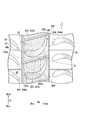
- FIG. 5 is a cross-sectional view taken along line VV in FIG. 4.
- FIG. 5 is a sectional view taken along line VI-VI in FIG. 4.
- the gas turbine includes a compressor 10 that compresses air, a combustor 20 that generates combustion gas by burning fuel in the compressed air compressed by the compressor 10, and And a turbine 30 driven by combustion gas.
- the compressor 10 includes a compressor rotor 11 that rotates about an axis Ar, and a compressor casing 15 that covers the compressor rotor 11.
- the turbine 30 includes a turbine rotor 31 that rotates about an axis Ar and a turbine casing 35 that covers the turbine rotor 31.
- the combustor 20 is fixed to the turbine casing 35.
- the compressor rotor 11 and the turbine rotor 31 are located on the same axis Ar and connected to each other to form the gas turbine rotor 1.
- the compressor casing 15 and the turbine casing 35 are connected to each other to form the gas turbine casing 5.
- the direction in which the axis Ar extends is the axial direction Da
- the side where the compressor 10 is present with respect to the turbine 30 in the axial direction Da is the shaft upstream side Dau
- the opposite side is the shaft downstream side Dad.
- the upstream side in the rotational direction of the rotating gas turbine rotor 1 is defined as a rotational upstream side Dcu
- the opposite side is defined as a rotational downstream side Dcd.
- the radial direction with respect to the axis Ar is simply referred to as a radial direction Dr.
- the turbine rotor 31 has a rotor shaft 32 extending in the axial direction Da around the axis line Ar, and a plurality of rotor blade rows 33 attached to the rotor shaft 32.
- the rotor blade rows 33 are attached to the rotor shaft 32 so as to be separated from each other in the axial direction Da.
- Each of the blade rows 33 is composed of a plurality of blades 34 that are separated from each other in the circumferential direction Dc.
- the moving blade 34 has a wing body 34a extending in the radial direction Dr, and a platform 34b provided inside the wing body 34a in the radial direction Dr.
- the turbine 30 further includes a stationary blade row 43 disposed on the axial upstream side Dau of each rotor blade row 33, and a plurality of split rings 53 facing the rotor blade row 33 in the radial direction Dr.
- the stationary blade row 43 has a plurality of stationary blades 44 that are separated from each other in the circumferential direction Dc.
- the stationary blade 44 includes a blade body 44a extending in the radial direction Dr, an inner shroud 44b provided on the inner side in the radial direction Dr of the blade body 44a, and an outer shroud provided on the outer side in the radial direction Dr of the blade body 44a. 44c.
- the inner shrouds 44b and the outer shrouds 44c of the plurality of stationary blades 44 are arranged in the circumferential direction Dc to form an annular ring body around the axis Da.
- the plurality of split rings 53 are also arranged in the circumferential direction Dc to form an annular ring centered on the axis Da.
- annular combustion gas flow path GP is formed around the axis Ar.
- the annular combustion gas flow path GP is defined by the outer shroud 44 c of the stationary blade 44 and the split ring 53 on the outer peripheral side, and by the inner shroud 44 b of the stationary blade 44 and the platform 34 b of the moving blade 34 on the inner peripheral side.
- the combustion gas G from the combustor 20 flows through the combustion gas flow path GP.
- the moving blades 34, the stationary blades 44, and the split ring 53 are all gas turbine components that are exposed to the high-temperature combustion gas G.
- the split ring 100 of the present embodiment is configured to fix the flow path forming body 101 spreading in the axial direction Da and the circumferential direction Dc, and the flow path forming body 101 to the inner peripheral side of the turbine casing 35. And a hook 105.
- the hook 105 is provided outside the flow path forming body 101 in the radial direction Dr.
- the split ring 100 includes an intermediate structure 110 formed of a base material such as a nickel-based alloy, and a metal bond coat layer 120 that covers a part of the surface of the intermediate structure 110. And a ceramic layer 130 that covers a part of the surface of the bond coat layer 120.
- the bond coat layer 120 and the ceramic layer 130 covering a part of the surface of the intermediate structure 110 form a thermal barrier coating layer.
- the bond coat layer 120 has high oxidation resistance and reduces the difference between the thermal expansion amount of the ceramic layer 130 and the thermal expansion amount of the intermediate structure 110, and the adhesion between the intermediate structure 110 and the ceramic layer 130. It is made of a material that can secure the properties.
- the bond coat layer 120 is formed of, for example, an MCrAlY alloy.
- M is a metal containing at least one metal element among Ni, Co, and Fe.
- the ceramic layer 130 is made of, for example, a ZrO 2 -based ceramic. In FIG. 3 to FIG. 6, the region with a plurality of dots is the region where the ceramic layer 130 is formed.
- the intermediate structure 110 includes a pair of gas path surfaces 102 facing the combustion gas flow path GP in the radial direction Dr, that is, facing the inner side in the radial direction Dr, and a pair facing each other in the circumferential direction Dc.
- a side surface 103 and a pair of axial end surfaces 104 facing each other in the axial direction Da are formed.
- the bond coat layer 120 is formed on the gas path surface 102 and is formed on the gas path surface 102 side in the radial direction Dr within the pair of side surfaces 103 and the pair of axial end surfaces 104.
- the side surface 103 located on the rotation upstream side Dcu is defined as a rotation upstream side surface 103u
- the opposite side is defined as a rotation downstream side surface 103d
- the axial end surface 104 located on the axial upstream side Dau is defined as the axial upstream end surface 104u
- the opposite side is defined as the axial downstream end surface 104d.
- the corner between the gas path surface 102 and the rotation upstream side surface 103u is the rotation upstream corner portion 115u
- the corner between the gas path surface 102 and the rotation downstream side surface 103d is the rotation downstream corner portion 115d
- the gas path surface 102 and the shaft upstream end surface 104u are The corner is defined as the shaft upstream corner 116u
- the corner between the gas path surface 102 and the shaft downstream end surface 104d is defined as the shaft downstream corner 116d.
- the gas path surface 102 of the intermediate structure 110 includes an edge side gas path surface 112b included in the rotation upstream corner portion 115u and the shaft upstream corner portion 116u, and a gas path surface 102 excluding the edge side gas path surface 112b. And a main gas path surface 112a.
- the edge side gas path surface 112b is located closer to the combustion gas flow path GP than the main gas path surface 112a, that is, inside the radial direction Dr. More specifically, in the present embodiment, the edge side gas path surface 112b of the intermediate structure 110 is positioned on the inner side in the radial direction Dr by the thickness Tc of the ceramic layer 130 from the main gas path surface 112a.
- the rotational upstream corner 115u of the present embodiment is defined with reference to the intersection line I between the edge side gas path surface 112b forming the corner 115u and the rotational upstream side 103u adjacent thereto.
- the rotation upstream corner portion 115u is on the gas path surface 102, the portion from the intersection line I to the position of the predetermined distance Lc, and the rotation upstream side surface 103u adjacent to the gas path surface 102, and the intersection line I To the position of the distance Lc.
- the axial upstream corner portion 116u of the present embodiment is defined on the basis of the line of intersection between the edge gas path surface 112b and the axial upstream end surface 104u forming the corner portion 116u.
- the axial upstream corner portion 116u of the present embodiment includes a portion from this intersection line to a position at a predetermined distance on the gas path surface 102, and a portion from this intersection line to a position at a predetermined distance on the shaft upstream end surface 104u. It is a part formed by.
- the bond coat layer 120 and the ceramic layer 130 are formed on the entire main gas path surface 112a of the intermediate structure 110. As shown in FIG. 5, the ceramic layer 130 is not formed on the surface of the rotation upstream corner portion 115u of the intermediate structure 110, and the bond coat layer 120 is formed. That is, the bond coat layer 120 is exposed on the edge side gas path surface 112b and the rotation upstream side surface 103u included in the rotation upstream corner portion 115u.
- An opening of a cooling air hole 119 is formed on the surface of the rotary upstream corner portion 115u.
- the cooling air hole 119 extends in a direction having a radial Dr component, and jets cooling air existing outside the radial ring Dr of the split ring 100 into the combustion gas flow path GP from the aforementioned opening.
- the ceramic layer 130 is not formed on the surface of the axial upstream corner portion 116u of the intermediate structure 110, and the bond coat layer 120 is formed. That is, the bond coat layer 120 is exposed on the edge side gas path surface 112b and the shaft upstream end surface 104u included in the shaft upstream corner portion 116u.
- a bond coat layer 120 and a ceramic layer 130 are formed on the surface of the shaft downstream corner portion 116d and the surface of the rotating downstream corner portion 115d of the intermediate structure 110.
- the shaft upstream corner and the rotation upstream corner of the intermediate structure in the present embodiment, the second embodiment to be described later, and various modifications are the shaft upstream corner or the rotation upstream corner of the gas turbine component that is a finished product. But there is. Therefore, a metal member is exposed on the surface of the shaft upstream corner or the rotary upstream corner.
- the thickness Tb2 of the portion of the bond coat layer 120 whose surface is not covered with the ceramic layer 130 may be thicker than the thickness Tb1 of the portion of the bond coat layer 120 whose surface is covered with the ceramic layer 130.
- the intermediate structure 110 is manufactured (S1: intermediate structure manufacturing process).
- the base material such as a nickel-base alloy is formed by casting or the like so that it has a substantially desired shape. Subsequently, it is machined as necessary to adjust the shape.
- the bond coat layer 120 is formed on the gas path surface 102, and the bond coat layer 120 is formed on the gas path surface 102 side in the radial direction Dr within the pair of side surfaces 103 and the pair of axial end surfaces 104 (S2: Bond coat layer forming step).
- the bond coat layer 120 is formed by spraying the sprayed powder such as the aforementioned MCrAlY alloy on the surface of the intermediate structure 110.
- the bond coat layer 120 may be formed by welding an MCrAlY alloy or the like to the surface of the intermediate structure 110.
- the above-described ceramic spray powder such as ZrO 2 is sprayed on the surface of the intermediate structure 110 including the portion where the ceramic layer 130 is formed (S3: coating step). At this time, the ceramic spray powder is sprayed so that the thickness of the ceramic layer 130 is slightly larger than the target thickness.
- the surface layer portion of the ceramic layer 130 formed in the covering step (S3) is removed by grinding or polishing (S4: partial removal step).
- the ceramic layer is not only formed on the main gas path surface 112a that is the surface on which the ceramic layer 130 is to be formed among the surfaces of the intermediate structure 110, but also on the edge side gas path surface 112b on which the ceramic layer 130 is not formed. 130 is formed. Therefore, here, the surface layer portion of the ceramic layer 130 formed in the coating step (S3) is ground or polished until the surface of the bond coat layer 120 forming the edge gas path surface 112b is exposed.
- the bond coat layer 120 that forms the edge side gas path surface 112b in the partial removal step (S4) is ground or polished until the surface is exposed. For this reason, in this embodiment, the surface of the ceramic layer 130 on the main gas path surface 112a and the surface of the bond coat layer 120 forming the edge side gas path surface 112b can be easily made flush.
- the surface of the split ring 100 to be repaired is ground or polished to remove at least the ceramic layer 130 (S11: first removal step).
- first removal step all or part of the bond coat layer 120 may be removed along with the removal of the ceramic layer 130.
- the bond coat layer 120 is additionally formed on the surface of the split ring 100 from which the ceramic layer 130 has been removed, and the ceramic layer 130 is formed thereon (S12: coating step).
- the ceramic spray powder is sprayed so that the thickness of the ceramic layer 130 is slightly larger than the target thickness, as in the above-described coating step (S3).
- the surface layer portion of the ceramic layer 130 formed in the covering step (S12) is removed by grinding or polishing (S13: second removal step).
- the ceramic layer 130 formed in the covering step (S12) is exposed until the surface of the bond coat layer 120 forming the edge gas path surface 112b is exposed, as in the partial removal step (S4) described above. Grind or polish the surface layer. Therefore, the surface of the ceramic layer 130 on the main gas path surface 112a and the surface of the bond coat layer 120 on the edge side gas path surface 112b can be easily flushed.
- the flow G1 of the combustion gas G flowing from the stationary blade 44 to the moving blade 34 is a flow toward the rotating downstream side Dcd while moving toward the axial downstream side Dad.
- the foreign gas such as metal powder
- the foreign material collides with the portion on the rotary upstream side Dcu of the split ring 100 at an angle close to 90 °.
- the cooling air may also contain foreign matters such as metal powder. In this case, the foreign matter in the cooling air collides with the portion upstream of the axis Dau of the split ring 100 at an angle close to 90 °.
- the cooling air may also contain foreign matters such as metal powder.
- the foreign matter in the cooling air collides with the rotation upstream side Dcu of the split ring 100 at an angle close to 90 °.
- the ceramic layer 130 is formed on the axial upstream side Dau portion and the rotational upstream side Dcu portion of the split ring 100, a part of the ceramic layer 130 is peeled off by the foreign matter colliding with these portions. The possibility to do increases. Once a part of the ceramic layer 130 is peeled off, thinning by erosion proceeds from the peeled part.
- the axial upstream side Dau portion and the rotational upstream side Dcu portion of the split ring 100 more specifically, the surface of the shaft upstream corner portion 116u in the intermediate structure 110 of the split ring 100, and this The metal bond coat layer 120 is exposed without forming the ceramic layer 130 on the surface of the rotation upstream corner portion 115u of the intermediate structure 110.
- the erosion speed of the member formed of ceramics gradually increases as the collision angle of foreign matter on the surface approaches 90 °. For this reason, if the ceramic layer 130 is formed on the surface of the shaft upstream corner portion 116u and the surface of the rotating upstream corner portion 115u in the split ring 100 where the collision angle of the foreign matter is close to 90 °, the erosion speed of this portion is increased. It becomes higher than the erosion speed of other parts.
- a member formed of a metal that is a ductile material has a high erosion speed when the collision angle of foreign matter on the surface is about 20 °, but gradually increases as the collision angle approaches from 90 ° to 90 °. The erosion speed decreases. For this reason, when the collision angle is close to 90 °, the erosion speed of the metal member is much lower than that of the ceramic member.
- the ceramic layer 130 is not formed on the surface of the shaft upstream corner portion 116u and the surface of the rotating upstream corner portion 115u in the split ring 100, and a metal bond coat is formed. Since the layer 120 is exposed, erosion of this portion can be suppressed. Furthermore, in this embodiment, peeling of the ceramic layer 130 due to erosion can be suppressed.
- the bond coat layer 120 exposed on the surface of the shaft upstream corner portion 116u and the surface of the rotating upstream corner portion 115u in the split ring 100 is formed of a metal having high oxidation resistance. , Oxidation at this portion can be suppressed.
- the thickness Tb2 of the bond coat layer 120 exposed on the surface of the shaft upstream corner portion 116u and the surface of the rotation upstream corner portion 115u is a bond in which the ceramic layer 130 is formed on the surface. Since it is thicker than the thickness Tb1 of the coat layer 120, the oxidation resistance can be further enhanced.
- the opening of the cooling air hole 119 is formed on the surface of the rotation upstream corner portion 115u, and the cooling air is ejected from this opening, so that this portion where the ceramic layer 130 is not formed can be cooled. it can.
- the opening of the cooling air hole 119 is formed on the surface of the rotating upstream corner portion 115u.
- the opening of the cooling air hole may be formed on the surface of the shaft upstream corner portion 116u.
- the ceramic layer 130 is not formed on the entire axial direction Da in the rotational upstream corner portion 115u, and the bond coat layer 120 is exposed, but the axial direction Da in the rotational upstream corner portion 115u is exposed.
- the bond coat layer 120 may be exposed on the upstream side, and the ceramic layer 130 may be formed on the downstream side.
- the speed of the circumferential direction Dc component of the flow G2 of the combustion gas flowing from the moving blade 34 to the stationary blade 44 is smaller than the speed of the circumferential direction Dc component of the flow G1 of the combustion gas G flowing from the stationary blade 44 to the moving blade 34.
- region of the shaft downstream side Dad in the rotation upstream corner part 115u is smaller than the collision speed of the foreign object with respect to the area
- the ceramic layer is not formed at both corners of the shaft upstream corner and the rotation upstream corner, and the metal that is a ductile material is exposed, but the shaft upstream corner and the rotation upstream corner are exposed.
- a ceramic layer may be formed at one corner, and a metal that is a ductile material may be exposed at the other corner.
- a ceramic layer may be formed at the shaft upstream corner, and a metal that is a ductile material may be exposed at the rotation upstream corner.
- the gas turbine component of this embodiment is an outer shroud of a stationary blade.
- the outer shroud 200 of the present embodiment includes a flow path forming body 201 extending in the axial direction Da and the circumferential direction Dc, and a hook for fixing the outer shroud 200 to the inner peripheral side of the turbine casing 35. 205.
- the hook 205 is provided outside the flow path forming body 201 in the radial direction Dr.
- the vane body 44 a of the stationary blade is provided inside the flow path forming body 201 in the radial direction Dr.
- the outer shroud 200 is also made of an intermediate structure 210 made of metal and a metal bond coat layer covering a part of the surface of the intermediate structure 210, as shown in FIG. 120 and a ceramic layer 130 covering a part of the surface of the intermediate structure 210.
- the bond coat layer 120 and the ceramic layer 130 covering a part of the surface of the intermediate structure 210 form a thermal barrier coating layer.
- the intermediate structure 210 includes a gas path surface 202 that faces the combustion gas flow path GP in the radial direction Dr, that is, an inner side in the radial direction Dr, a pair of side surfaces 203 that face each other in the circumferential direction Dc, and that faces each other in the axial direction Da. And a pair of axial end faces 204 are formed.
- the bond coat layer 120 is formed on the gas path surface 202 and is formed on the gas path surface 202 side in the radial direction Dr in the pair of side surfaces 203 and the pair of axial end surfaces 204.
- the side surface 203 located on the rotation upstream side Dcu is defined as a rotation upstream side surface 203u
- the opposite side is defined as a rotation downstream side surface 203d
- the axial end surface 204 located on the axial upstream side Dau is defined as the axial upstream end surface 204u
- the opposite side is defined as the axial downstream end surface 204d.
- the corner between the gas path surface 202 and the rotation upstream side surface 203u is the rotation upstream corner 215u
- the corner between the gas path surface 202 and the rotation downstream side 203d is the rotation downstream corner 215d
- the gas path surface 202 and the shaft upstream end surface 204u are The corner is defined as the shaft upstream corner 216u
- the corner between the gas path surface 202 and the shaft downstream end surface 204d is defined as the shaft downstream corner 216d.
- the gas path surface 202 of the intermediate structure 210 includes an edge side gas path surface 212b included in the axial upstream corner portion 216u and the rotational upstream corner portion 215u, and a main gas path surface 212a that is the gas path surface 202 excluding the edge side gas path surface 212b.
- the edge-side gas path surface 212b is positioned on the combustion gas flow path GP side, that is, on the radial direction Dr side from the main gas path surface 212a by approximately the thickness Tc of the ceramic layer 130.
- the bond coat layer 120 and the ceramic layer 130 are formed on the entire main gas path surface 212a of the intermediate structure 210.
- the ceramic layer 130 is not formed on the surface of the rotation upstream corner portion 215u of the intermediate structure 210, and the bond coat layer 120 is formed. That is, the bond coat layer 120 is exposed on the edge side gas path surface 212b and the rotation upstream side surface 203u included in the rotation upstream corner portion 215u.
- the bond coat layer 120 is also exposed on the surface of the axial upstream corner 216u of the intermediate structure 210. That is, the ceramic layer 130 is not formed on the edge side gas path surface 212b and the shaft upstream end surface 204u included in the shaft upstream corner portion 216u, and the bond coat layer 120 is formed.
- a bond coat layer 120 and a ceramic layer 130 are formed on the surface of the shaft downstream corner 216d and the surface of the rotation downstream corner 215d of the intermediate structure 210.
- the thickness of the ceramic layer 130 and the thickness of the bond coat layer 120 in this embodiment are the same as those in the first embodiment.
- the definition of the corner in this embodiment is the same as the definition of the corner in the first embodiment.
- the outer shroud 200 described above is manufactured in the same manner as the method for manufacturing the split ring 100 described above. Further, the outer shroud 200 is repaired in the same manner as the repair method of the split ring 100 described above. However, the outer shroud 200 is not manufactured or repaired alone, but is manufactured or repaired integrally with the wing body and the inner shroud.
- the combustion gas flow G2 flowing from the moving blade 34 to the stationary blade 44 in the combustion gas flow path GP is a flow in the circumferential direction Dc while moving toward the axial downstream side Dad.
- the combustion gas flow G1 flowing from the stationary blade 44 to the moving blade 34 is a flow toward the rotating downstream side Dcd while moving toward the axial downstream side Dad.
- the foreign gas such as metal powder is included in the combustion gas G, the foreign matter collides with the portion of the outer shroud 200 on the rotational upstream side Dcu at an angle close to 90 °.
- some of the split rings 54 on the shaft upstream side Dau of the outer shroud 200 eject cooling air to the shaft downstream side Dad.
- the cooling air may also contain foreign matters such as metal powder.
- the foreign matter in the cooling air collides with the axial upstream side Dau of the outer shroud 200 at an angle close to 90 °.
- some of the other outer shrouds 200 arranged on the rotation upstream side Dcu of the outer shroud 200 eject cooling air from the rotation downstream side surface 203d to the rotation downstream side Dcd.
- the cooling air may also contain foreign matters such as metal powder. In this case, the foreign matter in the cooling air collides with the rotation upstream side Dcu of the outer shroud 200 at an angle close to 90 °.
- the ceramic layer 130 is formed on the axial upstream side Dau portion and the rotational upstream side Dcu portion of the outer shroud 200, a part of the ceramic layer 130 is peeled off by foreign matter colliding with these portions. The possibility to do increases. Therefore, also in the present embodiment, as in the split ring 100 of the first embodiment, the axial upstream side Dau portion and the rotational upstream side Dcu portion of the outer shroud 200, more specifically, the intermediate structure 210 of the outer shroud 200.
- the metal bond coat layer 120 is exposed without forming the ceramic layer 130 on the surface of the shaft upstream corner 216u and the surface of the rotation upstream corner 215u of the intermediate structure 210.
- erosion of the shaft upstream corner 216u in the intermediate structure 210 of the outer shroud 200 and the rotation upstream corner 215u in this intermediate structure 210 is suppressed. Can do. Furthermore, also in this embodiment, peeling of the ceramic layer 130 due to erosion can be suppressed.
- the bond coat layer 120 exposed on the surface of the shaft upstream corner portion 216u in the intermediate structure 210 of the outer shroud 200 and the surface of the rotation upstream corner portion 215u in the intermediate structure 210 has an acid resistance. Since it is formed of a metal having high chemical properties, oxidation at this portion can be suppressed.
- the ceramic layer 130 is not formed on the entire axial direction Da in the rotational upstream corner portion 215u and the bond coat layer 120 is exposed, but the axial direction Da in the rotational upstream corner portion 215u is exposed.
- the bond coat layer 120 may be exposed on the downstream side, and the ceramic layer 130 may be formed on the upstream side.
- the speed of the circumferential direction Dc component of the combustion gas flow G2 shown in FIG. 11 is smaller than the speed of the circumferential direction Dc component of the combustion gas flow G1.
- angular part 215u is smaller than the collision speed of the foreign object with respect to the area
- an opening for the cooling air hole may be formed on the surface of the rotary upstream corner portion 215u or the surface of the shaft upstream corner portion 116u. In each of the modifications described later, an opening for the cooling air hole may be formed on the surface of the rotary upstream corner or the surface of the shaft upstream corner.
- the gas turbine component 300 of the present modification is also made of a metal that covers an intermediate structure 110h formed of metal and a part of the surface of the intermediate structure 110h, as shown in FIG.
- the bond coat layer 120h and the ceramic layer 130 covering a part of the surface of the intermediate structure 110h are formed.
- the intermediate structure 110h also includes a gas path surface 102 facing the combustion gas flow path GP in the radial direction Dr, a pair of side surfaces 103 facing each other in the circumferential direction Dc, and a pair of axial end surfaces facing each other in the axial direction Da. 104.
- the gas path surface 102 includes an edge side gas path surface 112b included in the rotational upstream corner portion 115u and the shaft upstream corner portion 116u of the intermediate structure 110h, and a main gas path surface 112a that is the gas path surface 102 excluding the edge side gas path surface 112b. .
- the edge-side gas path surface 112b is positioned on the combustion gas flow path GP side, that is, on the radial direction Dr side from the main gas path surface 112a by approximately the thickness Tc of the ceramic layer 130.
- the bond coat layer 120h is formed on the main gas path surface 112a of the intermediate structure 110h, the surface of the shaft downstream corner of the intermediate structure 110h, and the surface of the rotation downstream corner of the intermediate structure 110h.
- the bond coat layer 120h is not formed on the surface of the axial upstream corner portion 116u of the intermediate structure 110h and the surface of the rotational upstream corner portion 115u of the intermediate structure 110h.
- the ceramic layer 130 is formed on the entire surface of the bond coat layer 120h, and is not formed in a region where the bond coat layer 120h is not formed. Therefore, the ceramic layer 130 is not formed on the surface of the shaft upstream corner portion 116u of the intermediate structure 110h where the bond coat layer 120h is not formed and the surface of the rotation upstream corner portion 115u of the intermediate structure 110h. Therefore, in this modification, the shaft upstream corner portion 116u of the intermediate structure 110h forms the shaft upstream corner portion of the gas turbine component 300, and the metal intermediate structure 110h is exposed on this surface. In this modification, the rotation upstream corner 115u of the intermediate structure 110h forms the rotation upstream corner of the gas turbine component 300, and the metal intermediate structure 110h is exposed on this surface.
- the edge side gas path surface 112b of the intermediate structure 110 is positioned closer to the combustion gas flow path GP than the main gas path surface 112a of the intermediate structure 110. That is, the edge side gas path surface 112 b of the intermediate structure 110 is discontinuous with respect to the main gas path surface 112 a of the intermediate structure 110.
- the edge side gas path surface 112bi of the intermediate structure 110i is flush with the main gas path surface 112ai of the intermediate structure 110i. That is, the edge side gas path surface 112bi is continuous with the main gas path surface 112ai.
- the main gas path on the gas path surface 402 of the gas turbine component 400 is obtained by making the thickness of the bond coat layer 120i on the edge side gas path surface 112bi of the intermediate structure 110i substantially the thickness of the ceramic layer 130.
- the surface 402a and the edge side gas path surface 402b are flush with each other.
- the main gas path surface 402a of the gas turbine component 400 is a gas path surface on the main gas path surface 112ai of the intermediate structure 110i in the gas path surface 402 of the gas turbine component 400.
- the edge gas path surface 402b of the gas turbine component 400 is a gas path surface on the edge gas path surface 112bi of the intermediate structure 110i in the gas path surface 402 of the gas turbine component 400.
- the gas turbine component 500 of this modification is formed by forming tapered surfaces 117 and 118 at the shaft upstream corner portion 116u and the rotating upstream corner portion 115u of the intermediate structure 110j.
- a bond coat layer 120j is formed on the surfaces of the axial upstream corner portion 116u and the rotational upstream corner portion 115u of the intermediate structure 110j of the present modification, as in the above embodiments. Therefore, the surfaces of the bond coat layer 120j formed on the tapered surfaces 117 and 118 in the axial upstream corner portion 116u and the rotational upstream corner portion 115u of the intermediate structure 110j also form inclined tapered surfaces 117j and 118j in the same manner.
- the taper surface 118 of the shaft upstream corner portion 116u gradually moves toward the shaft downstream side Dad as it goes toward the combustion gas flow path GP in the radial direction Dr.
- the taper surface 118 has a width Wt in the axial direction Da and a width Wt in the radial direction Dr as follows.
- 0.5Tc ⁇ Wt ⁇ Lc Tc is the thickness of the ceramic layer 130
- Lc is the corner width defined in the first embodiment.
- the base point of the width of the tapered surface 118 is the intersection line I of the extended surfaces of the two surfaces forming the corner.
- the width Wt in the axial direction Da and the width Wt in the radial direction Dr of the tapered surface 118 may be different from each other as long as the values satisfy the above formula.
- the taper surface 117 of the rotation upstream corner portion 115u gradually moves toward the rotation downstream side Dcd as it goes toward the combustion gas flow path GP in the radial direction Dr.
- the width Wt in the circumferential direction Dc and the width Wt in the radial direction Dr of the tapered surface 117 are the same as the values shown in the above formula.
- the erosion speed of the member formed of a metal gradually decreases as the collision angle of foreign matter or the like with respect to the surface approaches from 20 ° to 90 °.
- the tapered surfaces 117j and 118j are formed on the shaft upstream corner portion 116u and the rotation upstream corner portion 115u of the metallic intermediate structure 110j.
- the foreign matter collides with the taper surfaces 117j and 118j made of metal at a collision angle close to 90 °. For this reason, in this modification, the erosion in the shaft upstream corner and the rotation upstream corner of the gas turbine component 500 can be suppressed.
- the gas path surface of the gas turbine part is flush with the main gas path surface of the gas turbine part.
- the definitions of the edge gas path surface of the gas turbine component and the main gas path surface of the gas turbine component are the same as those described in the second modification of the gas turbine component.
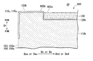
- the edge gas path surface 602b of the gas turbine component 600 is positioned closer to the combustion gas flow path GP in the radial direction Dr than the main gas path surface 602a of the gas turbine component 600.
- a bond coat layer 120k is formed on the surfaces of the axial upstream corner portion 116u and the rotational upstream corner portion 115u of the intermediate structure 110k of the present modification, as in the above embodiments, and the bond coat layer 120k is exposed. Yes.
- the tip clearance which is the distance in the radial direction Dr between the gas path surface of the split ring and the radial direction Dr outer end of the rotor blade facing the split ring in the radial direction Dr is a dimension that affects the performance of the gas turbine. Because it is, it is managed very strictly.
- the gas turbine component 600 of the present modification is a split ring, and the edge side gas path surface 602b of the rotation upstream corner portion 115u in this split ring is closer to the combustion gas flow path GP side in the radial direction Dr than the main gas path surface 602a.
- the edge side gas path surface 602b of the rotation upstream corner portion 115u in this split ring is closer to the combustion gas flow path GP side in the radial direction Dr than the main gas path surface 602a.
- the distance in the radial direction Dr between the edge side gas path surface 602b of the rotating upstream corner 115u and the outer end in the radial direction Dr of the rotor blade in the split ring is the distance between the main gas path surface 602a and the outer end in the radial direction Dr of the rotor blade. It becomes narrower than the interval in the radial direction Dr.
- the radial direction Dr between the main gas path surface 602a and the outer end in the radial direction Dr of the moving blade is treated as the above-described tip clearance, the radial direction Dr between the main gas path surface 602a and the outer end in the radial direction Dr of the moving blade.
- the performance of the gas turbine is reduced.
- the radial direction Dr between the main gas path surface 602a and the outer end in the radial direction Dr of the moving blade is treated as the above-described tip clearance
- the radial direction Dr between the edge side gas path surface 602b and the outer end in the radial direction Dr of the moving blade Is smaller than the tip clearance, there is a possibility that the moving blade contacts the edge side gas path surface 602b.
- the gas turbine component 600 of the present modification is a split ring
- only the edge side gas path surface 602b of the region that does not face the radial direction Dr end of the rotor blade is selected from the edge side gas path surface 602b of the split ring.
- the gas path surface 602a is preferably positioned closer to the combustion gas flow path GP in the radial direction Dr.
- the edge-side gas path surface 602b including the axial upstream corner portion 116u of the split ring may be positioned closer to the combustion gas flow path GP in the radial direction Dr than the main gas path surface 602a.
- edge side gas path surface 602b including the rotation upstream corner portion 115u of the split ring only the portion of the shaft upstream side Dau and the shaft downstream side Dad that are not opposed to the radial direction Dr end of the rotor blade is larger in diameter than the main gas path surface 602a. It may be positioned on the combustion gas flow path GP side in the direction Dr.
- the ceramic layer is not formed on both corners of the shaft upstream corner and the rotation upstream corner, and the metal which is a ductile material is exposed.
- a ceramic layer may be formed at one corner of the shaft upstream corner and the rotation upstream corner, and a metal that is a ductile material may be exposed at the other corner.
- a ceramic layer may be formed at the shaft upstream corner, and a metal that is a ductile material may be exposed at the rotation upstream corner.
- a ceramic layer may be formed at the rotation upstream corner portion, and the ductile material metal may be exposed at the shaft upstream corner portion.
- gas turbine parts of the embodiments and the modifications described above are all applied to the gas turbine parts that define the outer peripheral side of the annular combustion gas flow path GP, that is, the outer shroud and the split ring of the stationary blade.
- the present invention may be applied to gas turbine components that define the inner peripheral side of the annular combustion gas flow path GP, that is, the inner shroud of the stationary blade and the platform of the moving blade.
- the peeling of the ceramic layer in the gas turbine component can be suppressed.
Landscapes
- Engineering & Computer Science (AREA)
- Chemical & Material Sciences (AREA)
- Combustion & Propulsion (AREA)
- Mechanical Engineering (AREA)
- General Engineering & Computer Science (AREA)
- Materials Engineering (AREA)
- Turbine Rotor Nozzle Sealing (AREA)
- Coating By Spraying Or Casting (AREA)
Abstract
ガスタービン部品は、金属製の中間構造体(110)とセラミックス層(130)とを有する。中間構造体(110)は、径方向(Dr)で燃焼ガス流路(GP)側を向くガスパス面(102)と周方向Dcで互い対向する一対の側面(103)とが形成されている。セラミックス層(130)は、中間構造体(110)のガスパス面(102)上に形成されている。但し、このセラミックス層(130)は、一対の側面(103)のうち、ロータの回転方向における上流側の回転上流側面(103u)とガスパス面(102)との回転上流角部(115u)には、形成されていない。
Description
本発明は、ガスタービン内で燃焼ガス流路を画定するガスタービン部品、ガスタービン部品の中間構造体、ガスタービン、ガスタービン部品の製造方法、及びガスタービン部品の修理方法に関する。
本願は、2015年2月13日に、日本国に出願された特願2015-026468号に基づき優先権を主張し、この内容をここに援用する。
本願は、2015年2月13日に、日本国に出願された特願2015-026468号に基づき優先権を主張し、この内容をここに援用する。
ガスタービンは、圧縮空気を生成する圧縮機と、この圧縮空気中で燃料を燃焼させて燃焼ガスを生成する燃焼器と、燃焼ガスにより駆動するタービンと、を備えている。タービンは、軸線を中心として回転するタービンロータと、タービンロータを覆うタービンケーシングと、を有している。タービンロータは、軸線を中心として、軸線が延びる軸方向に延在するロータ軸と、このロータ軸に固定されている複数の動翼列と、を有している。複数の動翼列は、軸方向で互いに離間してロータ軸に固定され、軸線を基準とした周方向に並ぶ複数の動翼を有している。タービンは、さらに、各動翼列の上流側に配置されている静翼列と、軸線を中心として環状を成し、径方向で動翼列と対向する分割環と、を有している。
タービンを構成する部品のうち、動翼、静翼、及び分割環は、いずれも高温の燃焼ガスに曝される高温部品を成す。これらの高温部品は、いずれも高温の燃焼ガスによる損傷を軽減するための冷却手段を有している。例えば、特許文献1では、冷却通路が内部に形成された分割環が開示されている。
また、上記の高温部品は、金属製の母材の表面に遮熱コーティング(Thermal Barrier Coating : TBC)層が施されている。この遮熱コーティング層に関しては、例えば、特許文献2に記載されている。この遮熱コーティング層は、CoNiCrAlY等の金属で形成されるボンドコート層と、ZrO2系のセラミックで形成されるセラミックス層とを有している。ボンドコート層は、母材の表面に形成される。セラミックス層は、このボンドコート層の表面に形成される。ボンドコート層は、セラミックス層の熱膨張量と母材の熱膨張量との差を緩和し、母材とセラミックス層との間の密着性を確保する役目を主として担っている。
ここで、燃焼ガスが流れる流路には、燃焼ガスと共に、微細な金属粉等の異物が流れる。この異物が高温部品に衝突すると、この高温部品の表層を形成する遮熱コーティング層中のセラミックス層の一部にエロージョンによる減肉が生じる。すなわち、セラミックス層の一部が剥離する。一旦、セラミックス層の一部が剥離すると、この剥離した箇所からエロージョンによる減肉が進行する。このため、セラミックス層の剥離を抑制する必要がある。
そこで、本発明は、ガスタービン内で燃焼ガス流路を画定するガスタービン部品におけるセラミックス層の剥離を抑制することを目的とする。
前記目的を達成するための発明に係る第一態様としてのガスタービン部品は、
ガスタービン内で、軸線を中心として環状の燃焼ガス流路を画定し、前記軸線を基準として環状の環体を構成するガスタービン部品において、前記燃焼ガス流路側を向くガスパス面と、前記軸線を基準とした周方向で互いに対向する一対の側面と、前記軸線の方向で互いに対向する一対の軸方向端面とが形成されている金属製の中間構造体と、前記一対の側面のうち、前記軸線を中心として回転する前記ガスタービンのロータの回転方向における上流側にある回転上流側面と前記ガスパス面とから成る回転上流角部と、前記一対の軸方向端面のうち、前記燃焼ガス流路の上流側にある軸上流端面と前記ガスパス面とから成る軸上流角部とのうち、少なくとも一方の角部を残し、前記中間構造体の前記ガスパス面を被覆するセラミックス層と、を備える。
ガスタービン内で、軸線を中心として環状の燃焼ガス流路を画定し、前記軸線を基準として環状の環体を構成するガスタービン部品において、前記燃焼ガス流路側を向くガスパス面と、前記軸線を基準とした周方向で互いに対向する一対の側面と、前記軸線の方向で互いに対向する一対の軸方向端面とが形成されている金属製の中間構造体と、前記一対の側面のうち、前記軸線を中心として回転する前記ガスタービンのロータの回転方向における上流側にある回転上流側面と前記ガスパス面とから成る回転上流角部と、前記一対の軸方向端面のうち、前記燃焼ガス流路の上流側にある軸上流端面と前記ガスパス面とから成る軸上流角部とのうち、少なくとも一方の角部を残し、前記中間構造体の前記ガスパス面を被覆するセラミックス層と、を備える。
脆性材料であるセラミックスで形成された部材は、その表面に対する異物等の衝突角度が90°に近づくに連れて次第にエロージョン速度が高まる。一方、延性材料である金属で形成された部材は、その表面に対する異物等の衝突角度が90°に近づくに連れて次第にエロージョン速度が低下する。このため、衝突角度が90°に近い角度では、セラミックス部材よりも金属部材の方が遥にエロージョン速度が低い。
ガスタービン部品では、回転上流側面とガスパス面との回転上流角部や、軸上流端面と前記ガスパス面との軸上流角部には、燃焼ガス等中の異物が90°に近い衝突角度で衝突する。当該ガスタービン部品では、ガスタービン部品の角部になる中間構造体の角部の表面には、セラミックス層が形成されておらず、金属が露出している。このため、当該ガスタービン部品では、この角部のエロージョンを抑えることができる。さらに、当該ガスタービン部品では、エロージョンによるセラミックス層の剥離を抑えることができる。
前記目的を達成するための発明に係る第二態様としてのガスタービン部品は、
前記第一態様の前記ガスタービン部品において、前記セラミックス層は、少なくとも前記回転上流角部を残し、前記ガスパス面を被覆し、前記回転上流角部には、前記燃焼ガス流路側に向かうにつれて前記回転方向における下流側に傾斜する回転上流側テーパ面が形成されてもよい。
前記第一態様の前記ガスタービン部品において、前記セラミックス層は、少なくとも前記回転上流角部を残し、前記ガスパス面を被覆し、前記回転上流角部には、前記燃焼ガス流路側に向かうにつれて前記回転方向における下流側に傾斜する回転上流側テーパ面が形成されてもよい。
前記目的を達成するための発明に係る第三態様としてのガスタービン部品は、
前記第一又は前記第二態様の前記ガスタービン部品において、前記セラミックス層は、少なくとも前記軸上流角部を残し、前記ガスパス面を被覆し、前記軸上流角部には、前記燃焼ガス流路側に向かうにつれて前記軸線の方向で前記燃焼ガス流路の下流側に傾斜する軸上流側テーパ面が形成されてもよい。
前記第一又は前記第二態様の前記ガスタービン部品において、前記セラミックス層は、少なくとも前記軸上流角部を残し、前記ガスパス面を被覆し、前記軸上流角部には、前記燃焼ガス流路側に向かうにつれて前記軸線の方向で前記燃焼ガス流路の下流側に傾斜する軸上流側テーパ面が形成されてもよい。
当該ガスタービン部品の角部中のテーパ面は、金属の面である。このテーパ面に対して、異物等が90°に近い衝突角度で衝突する。前述したように、延性材料である金属で形成された部材は、その表面に対する異物等の衝突角度が90°に近づくに連れて次第にエロージョン速度が低下する。このため、当該ガスタービン部品では、角部のエロージョンを抑えることができる。
前記目的を達成するための発明に係る第四態様としてのガスタービン部品は、
前記第一又は第二態様の前記ガスタービン部品において、前記セラミックス層は、前記軸上流角部と前記回転上流角部とを残し、前記ガスパス面を被覆してもよい。
前記第一又は第二態様の前記ガスタービン部品において、前記セラミックス層は、前記軸上流角部と前記回転上流角部とを残し、前記ガスパス面を被覆してもよい。
前記目的を達成するための発明に係る第五態様としてのガスタービン部品は、
前記第一から第四態様のいずれかの前記ガスタービン部品において、前記中間構造体に対する前記セラミックス層の熱膨張量差を緩和する金属製のボンドコート層を備え、前記回転上流角部と前記回転上流角部とのうち、少なくとも一方の角部には、前記ボンドコート層が形成されてもよい。
前記第一から第四態様のいずれかの前記ガスタービン部品において、前記中間構造体に対する前記セラミックス層の熱膨張量差を緩和する金属製のボンドコート層を備え、前記回転上流角部と前記回転上流角部とのうち、少なくとも一方の角部には、前記ボンドコート層が形成されてもよい。
ボンドコート層は、中間構造体に対するセラミックス層の熱膨張量差を緩和する金属で形成されている。この金属は、耐酸化性の高い金属である。このため、当該ガスタービン部品では、金属が露出している角部の酸化を抑えることができる。
前記目的を達成するための発明に係る第六態様としてのガスタービン部品は、
前記第一から第五態様のいずれかの前記ガスタービン部品において、前記中間構造体には、前記回転上流角部又は前記軸上流角部から前記燃焼ガス流路内に空気を噴出する冷却空気孔が形成されてもよい。
前記第一から第五態様のいずれかの前記ガスタービン部品において、前記中間構造体には、前記回転上流角部又は前記軸上流角部から前記燃焼ガス流路内に空気を噴出する冷却空気孔が形成されてもよい。
当該ガスタービン部品では、冷却空気孔を流れる冷却空気により角部を冷却することができる。しかも、当該ガスタービン部品では、冷却空気孔から噴出する冷却空気により、この部分への異物の衝突を抑えることができ、この部分のエロージョンを抑えることができる。
前記目的を達成するための発明に係る第七態様としてのガスタービン部品は、
前記第一から第六態様のいずれかの前記ガスタービン部品において、前記ガスタービンの動翼と径方向で対向し、前記環状の燃焼ガス流路における外周側を画定する分割環を成してもよい。
前記第一から第六態様のいずれかの前記ガスタービン部品において、前記ガスタービンの動翼と径方向で対向し、前記環状の燃焼ガス流路における外周側を画定する分割環を成してもよい。
前記目的を達成するための発明に係る第八態様としてのガスタービン部品は、
前記第一から第六態様のいずれかの前記ガスタービン部品において、前記環状の燃焼ガス流路における外周側を画定し、前記ガスタービンの静翼における外側シュラウドを成してもよい。
前記第一から第六態様のいずれかの前記ガスタービン部品において、前記環状の燃焼ガス流路における外周側を画定し、前記ガスタービンの静翼における外側シュラウドを成してもよい。
前記目的を達成するための発明に係る第九態様としてのガスタービンは、
前記第一から第八態様のいずれかの前記ガスタービン部品と、前記ロータと、を備える。
前記第一から第八態様のいずれかの前記ガスタービン部品と、前記ロータと、を備える。
前記目的を達成するための発明に係る第十態様としてのガスタービン部品の中間構造体は、
ガスタービン内で、軸線を中心として環状の燃焼ガス流路を画定し、前記軸線を基準として環状の環体を構成する中間構造体において、金属で形成され、前記燃焼ガス流路側を向くガスパス面と、前記軸線を基準にした周方向で互いに対向する一対の側面と、前記軸線の方向で互いに対向する一対の軸方向端面とが形成され、前記ガスパス面は、セラミックス層で被覆されない縁側ガスパス面とセラミックス層で被覆される主ガスパス面とを有し、前記一対の側面のうち、前記軸線を中心として回転する前記ガスタービンのロータの回転方向における上流側にある回転上流側面と前記ガスパス面とから成る回転上流角部と、前記一対の軸方向端面のうち、前記燃焼ガス流路の上流側にある軸上流端面と前記ガスパス面とから成る軸上流角部とのうち、少なくとも一方の角部に含まれるガスパス面が、前記縁側ガスパス面を成し、残りのガスパス面が前記主ガスパス面を成し、前記縁側ガスパス面は、前記主ガスパス面よりも、前記軸線に対する径方向における前記燃焼ガス流路側に位置している。
ガスタービン内で、軸線を中心として環状の燃焼ガス流路を画定し、前記軸線を基準として環状の環体を構成する中間構造体において、金属で形成され、前記燃焼ガス流路側を向くガスパス面と、前記軸線を基準にした周方向で互いに対向する一対の側面と、前記軸線の方向で互いに対向する一対の軸方向端面とが形成され、前記ガスパス面は、セラミックス層で被覆されない縁側ガスパス面とセラミックス層で被覆される主ガスパス面とを有し、前記一対の側面のうち、前記軸線を中心として回転する前記ガスタービンのロータの回転方向における上流側にある回転上流側面と前記ガスパス面とから成る回転上流角部と、前記一対の軸方向端面のうち、前記燃焼ガス流路の上流側にある軸上流端面と前記ガスパス面とから成る軸上流角部とのうち、少なくとも一方の角部に含まれるガスパス面が、前記縁側ガスパス面を成し、残りのガスパス面が前記主ガスパス面を成し、前記縁側ガスパス面は、前記主ガスパス面よりも、前記軸線に対する径方向における前記燃焼ガス流路側に位置している。
前記目的を達成するための発明に係る第十一態様としてのガスタービン部品の製造方法は、
ガスタービン内で、軸線を中心として環状の燃焼ガス流路を画定し、前記軸線を基準として環状の環体を構成するガスタービン部品の製造方法において、前記軸線に対する径方向で前記燃焼ガス流路側を向くガスパス面と、前記軸線を基準にした周方向で互いに対向する一対の側面と、前記軸線の方向で互いに対向する一対の軸方向端面とが形成されている金属製の中間構造体を製造する中間構造体製造工程と、前記ガスパス面と、前記一対の側面と前記ガスパス面との角部の表面と、前記一対の軸方向端面と前記ガスパス面との角部の表面と、をセラミックス層で覆う被覆工程と、前記一対の側面のうち、前記軸線を中心として回転する前記ガスタービンのロータの回転方向における上流側にある回転上流側面と前記ガスパス面とから成る回転上流角部と、前記一対の軸方向端面のうち、前記燃焼ガス流路の上流側にある軸上流端面と前記前記ガスパス面とから成る軸上流角部とのうち、少なくとも一方の角部における前記セラミックス層を除去する部分除去工程と、を実行する。
ガスタービン内で、軸線を中心として環状の燃焼ガス流路を画定し、前記軸線を基準として環状の環体を構成するガスタービン部品の製造方法において、前記軸線に対する径方向で前記燃焼ガス流路側を向くガスパス面と、前記軸線を基準にした周方向で互いに対向する一対の側面と、前記軸線の方向で互いに対向する一対の軸方向端面とが形成されている金属製の中間構造体を製造する中間構造体製造工程と、前記ガスパス面と、前記一対の側面と前記ガスパス面との角部の表面と、前記一対の軸方向端面と前記ガスパス面との角部の表面と、をセラミックス層で覆う被覆工程と、前記一対の側面のうち、前記軸線を中心として回転する前記ガスタービンのロータの回転方向における上流側にある回転上流側面と前記ガスパス面とから成る回転上流角部と、前記一対の軸方向端面のうち、前記燃焼ガス流路の上流側にある軸上流端面と前記前記ガスパス面とから成る軸上流角部とのうち、少なくとも一方の角部における前記セラミックス層を除去する部分除去工程と、を実行する。
前記目的を達成するための発明に係る第十二態様としてのガスタービン部品の修理方法は、
ガスタービン内で、軸線を中心として環状の燃焼ガス流路を画定し、前記軸線を基準として環状の環体を構成するガスタービン部品の修理方法において、前記燃焼ガス流路側を向きセラミックス層が形成されているガスパス面と、前記軸線を基準にした周方向で互いに対向する一対の側面と、前記軸線の方向で互いに対向する一対の軸方向端面とが形成されている金属製の中間構造体から、前記セラミックス層を除去する第一除去工程と、前記ガスパス面と、前記一対の側面と前記ガスパス面との角部の表面と、前記一対の軸方向端面と前記ガスパス面との角部の表面と、をセラミックス層で覆う被覆工程と、前記一対の側面のうち、前記軸線を中心として回転する前記ガスタービンのロータの回転方向における上流側にある回転上流側面と前記ガスパス面とから成る回転上流角部と、前記一対の軸方向端面のうち、前記燃焼ガス流路の上流側にある軸上流端面と前記前記ガスパス面とから成る軸上流角部とのうち、少なくとも一方の角部における前記セラミックス層を除去する第二除去工程と、を実行する。
ガスタービン内で、軸線を中心として環状の燃焼ガス流路を画定し、前記軸線を基準として環状の環体を構成するガスタービン部品の修理方法において、前記燃焼ガス流路側を向きセラミックス層が形成されているガスパス面と、前記軸線を基準にした周方向で互いに対向する一対の側面と、前記軸線の方向で互いに対向する一対の軸方向端面とが形成されている金属製の中間構造体から、前記セラミックス層を除去する第一除去工程と、前記ガスパス面と、前記一対の側面と前記ガスパス面との角部の表面と、前記一対の軸方向端面と前記ガスパス面との角部の表面と、をセラミックス層で覆う被覆工程と、前記一対の側面のうち、前記軸線を中心として回転する前記ガスタービンのロータの回転方向における上流側にある回転上流側面と前記ガスパス面とから成る回転上流角部と、前記一対の軸方向端面のうち、前記燃焼ガス流路の上流側にある軸上流端面と前記前記ガスパス面とから成る軸上流角部とのうち、少なくとも一方の角部における前記セラミックス層を除去する第二除去工程と、を実行する。
本発明の一態様によれば、ガスタービン部品におけるセラミックス層の剥離を抑制できる。
以下、本発明に係る各種実施形態について、図面を参照して詳細に説明する。
「ガスタービンの実施形態」
本発明に係るガスタービンの一実施形態について、図1及び図2を参照して説明する。
本発明に係るガスタービンの一実施形態について、図1及び図2を参照して説明する。
本実施形態のガスタービンは、図1に示すように、空気を圧縮する圧縮機10と、圧縮機10で圧縮された圧縮空気中で燃料を燃焼させて燃焼ガスを生成する燃焼器20と、燃焼ガスにより駆動するタービン30と、を備えている。
圧縮機10は、軸線Arを中心として回転する圧縮機ロータ11と、圧縮機ロータ11を覆う圧縮機ケーシング15と、を有する。タービン30は、軸線Arを中心として回転するタービンロータ31と、タービンロータ31を覆うタービンケーシング35と、を有する。燃焼器20は、タービンケーシング35に固定されている。
圧縮機ロータ11とタービンロータ31とは、同一軸線Ar上に位置して互いに連結されてガスタービンロータ1を成す。また、圧縮機ケーシング15とタービンケーシング35とは、互いに連結されてガスタービンケーシング5を成す。なお、以下では、軸線Arが延びている方向を軸方向Da、この軸方向Daでタービン30に対して圧縮機10が存在する側を軸上流側Dau、反対側を軸下流側Dadとする。また、軸線Arを基準とした周方向Dcで、回転するガスタービンロータ1の回転方向における上流側を回転上流側Dcu、その反対側を回転下流側Dcdとする。さらに、軸線Arに対する径方向を単に径方向Drとする。
図2に示すように、タービンロータ31は、その軸線Arを中心として軸方向Daに延びるロータ軸32と、このロータ軸32に取り付けられている複数の動翼列33と、を有する。各動翼列33は、軸方向Daで互いに離間してロータ軸32に取り付けられている。各動翼列33は、いずれも周方向Dcで互いに離間した複数の動翼34で構成されている。動翼34は、径方向Drに延びる翼体34aと、この翼体34aの径方向Dr内側に設けられているプラットフォーム34bと、を有する。
タービン30は、さらに、各動翼列33の軸上流側Dauに配置されている静翼列43と、径方向Drで動翼列33と対向する複数の分割環53と、を有する。静翼列43は、周方向Dcで互いに離間した複数の静翼44を有している。静翼44は、径方向Drに延びる翼体44aと、この翼体44aの径方向Dr内側に設けられている内側シュラウド44bと、この翼体44aの径方向Dr外側に設けられている外側シュラウド44cと、を有する。複数の静翼44の各内側シュラウド44b及び各外側シュラウド44cは、周方向Dcに並び軸線Daを中心として環状の環体を構成する。また、複数の分割環53も、周方向Dcに並び軸線Daを中心として環状の環体を構成する。
タービンケーシング35内には、軸線Arを中心として環状の燃焼ガス流路GPが形成されている。この環状の燃焼ガス流路GPは、外周側が静翼44の外側シュラウド44cと分割環53とで画定され、内周側が静翼44の内側シュラウド44bと動翼34のプラットフォーム34bで画定される。この燃焼ガス流路GPには、燃焼器20からの燃焼ガスGが流れる。動翼34、静翼44及び分割環53は、いずれも、高温の燃焼ガスGに曝されるガスタービン部品である。
「ガスタービン部品の第一実施形態」
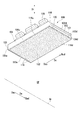
本発明に係るガスタービン部品の第一実施形態について、図3~図9を参照して説明する。図3に示す本実施形態のガスタービン部品は、前述した分割環である。
本発明に係るガスタービン部品の第一実施形態について、図3~図9を参照して説明する。図3に示す本実施形態のガスタービン部品は、前述した分割環である。
図3に示すように、本実施形態の分割環100は、軸方向Da及び周方向Dcに広がる流路形成体101と、この流路形成体101をタービンケーシング35の内周側に固定するためのフック105と、を有する。フック105は、流路形成体101の径方向Dr外側に設けられている。
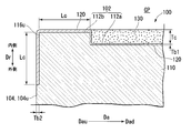
図5及び図6に示すように、分割環100は、ニッケル基合金等の母材で形成された中間構造体110と、中間構造体110の表面の一部を覆う金属製のボンドコート層120と、ボンドコート層120の表面の一部を覆うセラミックス層130と、で形成されている。中間構造体110の表面の一部を覆うボンドコート層120及びセラミックス層130は、遮熱コーティング層を形成する。ボンドコート層120は、高い耐酸化性を有すると共に、セラミックス層130の熱膨張量と中間構造体110の熱膨張量との差を緩和し、中間構造体110とセラミックス層130との間の密着性を確保できる材料で形成されている。このため、ボンドコート層120は、例えば、MCrAlY合金で形成される。ここで、Mは、NiとCoとFeとのうち、少なくとも一種の金属元素を含む金属である。また、セラミックス層130は、例えば、ZrO2系のセラミックで形成される。なお、図3~図6で、複数のドットが付されている領域は、セラミックス層130が形成された領域である。
中間構造体110には、図3及び図4に示すように、径方向Drで燃焼ガス流路GP側を向くつまり径方向Dr内側の向くガスパス面102と、周方向Dcで互いに対向する一対の側面103と、軸方向Daで互いに対向する一対の軸方向端面104と、が形成されている。ボンドコート層120は、ガスパス面102上に形成されると共に、一対の側面103内及び一対の軸方向端面104内の径方向Drにおけるガスパス面102側の部分に形成されている。
ここで、中間構造体110の一対の側面103のうち、回転上流側Dcuに位置する側面103を回転上流側面103uとし、その反対側を回転下流側面103dとする。また、中間構造体110の一対の軸方向端面104のうち、軸上流側Dauに位置する軸方向端面104を軸上流端面104uとし、その反対側を軸下流端面104dとする。さらに、ガスパス面102と回転上流側面103uとの角部を回転上流角部115u、ガスパス面102と回転下流側面103dとの角部を回転下流角部115d、ガスパス面102と軸上流端面104uとの角部を軸上流角部116u、ガスパス面102と軸下流端面104dとの角部を軸下流角部116dとする。
図5及び図6に示すように、中間構造体110のガスパス面102は、回転上流角部115u及び軸上流角部116uに含まれる縁側ガスパス面112bと、この縁側ガスパス面112bを除くガスパス面102である主ガスパス面112aとを有する。縁側ガスパス面112bは、主ガスパス面112aよりも、燃焼ガス流路GP側につまり径方向Dr内側に位置している。より具体的には、本実施形態では、中間構造体110の縁側ガスパス面112bは、主ガスパス面112aからほぼセラミックス層130の厚さTc分だけ、径方向Dr内側に位置している。
ここで、ガスパス面102と、このガスパス面102に隣接する各面で形成される角部について説明する。
図5に示すように、本実施形態の回転上流角部115uは、この角部115uを形成する縁側ガスパス面112bと、これに隣接する回転上流側面103uとの交線Iを基準に定義される。回転上流角部115uは、ガスパス面102上であって、交線Iから所定の距離Lcの位置までの部分と、このガスパス面102に隣接する回転上流側面103u上であって、同じく交線Iから距離Lcの位置までの部分とで形成される部分である。同様に、図6に示すように、本実施形態の軸上流角部116uは、この角部116uを形成する縁側ガスパス面112bと軸上流端面104uとの交線を基準に定義される。すなわち、本実施形態の軸上流角部116uは、この交線からガスパス面102上の所定の距離の位置までの部分と、この交線から軸上流端面104u上の所定の距離の位置までの部分とで形成される部分である。
中間構造体110の主ガスパス面112aの全面には、ボンドコート層120及びセラミックス層130が形成されている。中間構造体110の回転上流角部115uの表面には、図5に示すように、セラミックス層130が形成されておらず、ボンドコート層120が形成されている。すなわち、回転上流角部115uに含まれる縁側ガスパス面112b及び回転上流側面103uには、ボンドコート層120が露出している。この回転上流角部115uの表面には、冷却空気孔119の開口が形成されている。この冷却空気孔119は、径方向Dr成分を有する方向の延び、分割環100の径方向Dr外側に存在する冷却空気を前述の開口から燃焼ガス流路GP内に噴出する。
また、図6に示すように、中間構造体110の軸上流角部116uの表面にも、セラミックス層130が形成されておらず、ボンドコート層120が形成されている。すなわち、軸上流角部116uに含まれる縁側ガスパス面112b及び軸上流端面104uには、ボンドコート層120が露出している。一方、中間構造体110の軸下流角部116dの表面及び回転下流角部115dの表面には、ボンドコート層120及びセラミックス層130が形成されている。
なお、本実施形態、後述する第二実施形態及び各種変形例では、いずれも中間構造体の軸上流角部及び回転上流角部には、セラミックス層が形成されない。このため、本実施形態、後述する第二実施形態及び各種変形例における中間構造体の軸上流角部及び回転上流角部は、完成品であるガスタービン部品の軸上流角部又は回転上流角部でもある。よって、この軸上流角部又は回転上流角部の表面には、金属製の部材が露出している。
ボンドコート層120で表面がセラミックス層130で覆われていない部分の厚さTb2は、ボンドコート層120で表面がセラミックス層130で覆われている部分の厚さTb1より厚くてもよい。
次に、以上で説明した分割環100の製造手順について、図7に示すフローチャートに従って説明する。
まず、中間構造体110を製造する(S1:中間構造体製造工程)。この中間構造体製造工程(S1)では、例えば、ニッケル基合金等の母材がほぼ目的の形状になるように鋳造等で成形する。続いて、必要に応じて機械加工して形状を整える。つぎに、ガスパス面102にボンドコート層120を形成すると共に、一対の側面103及び一対の軸方向端面104内の径方向Drにおけるガスパス面102側の部分にボンドコート層120を形成する(S2:ボンドコート層形成工程)。ボンドコート層120は、前述のMCrAlY合金等の溶射粉を中間構造体110の表面に溶射することで形成される。なお、ボンドコート層120は、中間構造体110の表面にMCrAlY合金等を溶接することで形成してもよい。
次に、中間構造体110の表面のうち、セラミックス層130を形成する部分を含む領域に、前述のZrO2系等のセラミック溶射粉を溶射する(S3:被覆工程)。この際、セラミックス層130の厚さが目的の厚さよりも若干厚くなるよう、セラミックス溶射粉を溶射する。
次に、被覆工程(S3)で形成したセラミックス層130の表層部分を研削又は研磨等で除去する(S4:部分除去工程)。被覆工程(S3)では、中間構造体110の表面のうちでセラミックス層130を形成すべき面である主ガスパス面112a上のみならず、セラミックス層130を形成しない縁側ガスパス面112b上にもセラミックス層130が形成される。そこで、ここでは、縁側ガスパス面112bを成すボンドコート層120の表面が露出するまで、被覆工程(S3)で形成したセラミックス層130の表層部分を研削又は研磨する。
以上のように、本実施形態では、被覆工程(S3)で目的の厚さよりも厚くなるようセラミックス層130を形成した後、部分除去工程(S4)で縁側ガスパス面112bを成すボンドコート層120の表面が露出するまで、被覆工程(S3)で形成したセラミックス層130の表層部分を研削又は研磨する。このため、本実施形態では、主ガスパス面112a上のセラミックス層130の表面と縁側ガスパス面112bを成すボンドコート層120の表面とを容易に面一にすることができる。
次に、分割環100の修理手順について、図8に示すフローチャートに従って説明する。
まず、修理対象の分割環100の表面を研削又は研磨し、少なくともセラミックス層130を全て除去する(S11:第一除去工程)。この第一除去工程(S11)では、このセラミックス層130の除去に伴いボンドコート層120全て又は一部を除去してもよい。
次に、セラミックス層130が除去された分割環100の表面にボンドコート層120を追加形成すると共に、その上にセラミックス層130を形成する(S12:被覆工程)。セラミックス層130形成の際には、前述の被覆工程(S3)と同様、セラミックス層130の厚さが目的の厚さよりも若干厚くなるよう、セラミックス溶射粉を溶射する。
次に、被覆工程(S12)で形成したセラミックス層130の表層部分を研削又は研磨等で除去する(S13:第二除去工程)。この第二除去工程(S13)では、前述の部分除去工程(S4)と同様、縁側ガスパス面112bを成すボンドコート層120の表面が露出するまで、被覆工程(S12)で形成したセラミックス層130の表層部分を研削又は研磨する。従って、主ガスパス面112a上のセラミックス層130の表面と縁側ガスパス面112b上のボンドコート層120の表面とを容易に面一にすることができる。
次に、以上で説明した分割環100の作用効果について説明する。
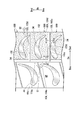
図4に示すように、燃焼ガス流路GP内で、静翼44から動翼34に流れる燃焼ガスGの流れG1は、軸下流側Dadに向かいつつ回転下流側Dcdに向かう流れである。このため、燃焼ガスG中に金属粉等の異物が含まれている場合、分割環100の回転上流側Dcuの部分に対して、この異物が90°に近い角度で衝突する。
また、分割環100の軸上流側Dauに配置されている静翼44の外側シュラウド44cには、軸下流側Dadに冷却空気を噴出するものがある。この冷却空気中にも金属粉等の異物が含まれることがある。この場合には、分割環100の軸上流側Dauに部分に対して、冷却空気中の異物が90°に近い角度で衝突する。
また、分割環100の回転上流側Dcuに配置されている他の分割環100には、その回転下流側面103dから回転下流側Dcdに冷却空気を噴出するものがある。この冷却空気中にも金属粉等の異物が含まれることがある。この場合には、分割環100の回転上流側Dcuに部分に対して、冷却空気中の異物が90°に近い角度で衝突する。
このため、仮に、分割環100の軸上流側Dauの部分及び回転上流側Dcuの部分にセラミックス層130が形成されていると、これらの部分に衝突する異物により、セラミックス層130の一部が剥離する可能性が高まる。一旦、セラミックス層130の一部が剥離すると、この剥離した箇所からエロージョンによる減肉が進行する。
そこで、本実施形態では、分割環100の軸上流側Dauの部分及び回転上流側Dcuの部分、より具体的には、分割環100の中間構造体110における軸上流角部116uの表面、及びこの中間構造体110における回転上流角部115uの表面には、セラミックス層130を形成せずに、金属製のボンドコート層120を露出させている。
図9に示すように、脆性材料であるセラミックスで形成された部材は、その表面に対する異物等の衝突角度が90°に近づくに連れて次第にエロージョン速度が高まる。このため、異物の衝突角度が90°に近い、分割環100における軸上流角部116uの表面、及び回転上流角部115uの表面にセラミックス層130が形成されていると、この部分のエロージョン速度が他の部分のエロージョン速度よりも高くなる。一方、延性材料である金属で形成された部材は、その表面に対する異物等の衝突角度が20°程度の場合、エロージョン速度が高いものの、衝突角度が20°程度から90°に近づくに連れて次第にエロージョン速度が低下する。このため、衝突角度が90°に近い角度では、セラミックス部材よりも金属部材の方が遥にエロージョン速度が低い。
したがって、本実施形態では、前述したように、分割環100における軸上流角部116uの表面、及び回転上流角部115uの表面には、セラミックス層130が形成されておらず、金属製のボンドコート層120が露出しているので、この部分のエロージョンを抑えることができる。さらに、本実施形態では、エロージョンによるセラミックス層130の剥離を抑えることができる。
また、本実施形態では、分割環100における軸上流角部116uの表面、及び回転上流角部115uの表面で露出しているボンドコート層120は、耐酸化性の高い金属で形成されているので、この部分における酸化を抑えることができる。しかも、本実施形態では、軸上流角部116uの表面、及び回転上流角部115uの表面で露出しているボンドコート層120の厚さTb2が、表面上にセラミックス層130が形成されているボンドコート層120の厚さTb1より厚いため、より耐酸化性を高めることができる。
さらに、本実施形態では、回転上流角部115uの表面に冷却空気孔119の開口が形成され、この開口から冷却空気が噴出するので、セラミックス層130が形成されていないこの部分を冷却することができる。なお、本実施形態では、回転上流角部115uの表面に冷却空気孔119の開口が形成されているが、軸上流角部116uの表面に冷却空気孔の開口が形成されていてもよい。また、本実施形態では、回転上流角部115uにおける軸方向Daの全体にセラミックス層130が形成されておらず、ボンドコート層120が露出しているが、回転上流角部115uにおける軸方向Daの上流側ではボンドコート層120を露出させ、下流側ではセラミックス層130を形成してもよい。
ここで、図4に示す燃焼ガスの流れG1と燃焼ガスの流れG2について説明する。動翼34から静翼44に流れる燃焼ガスの流れG2の周方向Dc成分の速度は、静翼44から動翼34に流れる燃焼ガスGの流れG1の周方向Dc成分の速度よりも小さい。このため、回転上流角部115uにおける軸下流側Dadの領域に対する異物の衝突速度は、この回転上流角部115uにおける軸上流側Dauの領域に対する異物の衝突速度よりも小さい。したがって、回転上流角部115uにおける軸下流側Dadには、前述したように、セラミックス層130を施してもよい。
また、本実施形態では、軸上流角部及び回転上流角部の両角部には、セラミックス層が形成されておらず、延性材料である金属が露出しているが、軸上流角部と回転上流角部とのうち、一方の角部にはセラミックス層が形成され、他方の角部では延性材料である金属が露出してもよい。例えば、軸上流角部にはセラミックス層が形成され、回転上流角部では延性材料である金属が露出してもよい。
「ガスタービン部品の第二実施形態」
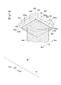
本発明に係るガスタービン部品の第二実施形態について、図10~図12を参照して説明する。本実施形態のガスタービン部品は、静翼の外側シュラウドである。
本発明に係るガスタービン部品の第二実施形態について、図10~図12を参照して説明する。本実施形態のガスタービン部品は、静翼の外側シュラウドである。
図10に示すように、本実施形態の外側シュラウド200は、軸方向Da及び周方向Dcに広がる流路形成体201と、この外側シュラウド200をタービンケーシング35の内周側に固定するためのフック205と、を有する。フック205は、流路形成体201の径方向Dr外側に設けられている。また、静翼の翼体44aは、流路形成体201の径方向Dr内側に設けられている。
この外側シュラウド200も、前述の分割環100と同様、図12に示すように、金属で形成されている中間構造体210と、中間構造体210の表面の一部を覆う金属製のボンドコート層120と、中間構造体210の表面の一部を覆うセラミックス層130と、で形成されている。中間構造体210の表面の一部を覆うボンドコート層120及びセラミックス層130は、遮熱コーティング層を形成する。
中間構造体210には、径方向Drで燃焼ガス流路GP側を向くつまり径方向Dr内側の向くガスパス面202と、周方向Dcで互いに対向する一対の側面203と、軸方向Daで互いに対向する一対の軸方向端面204と、が形成されている。ボンドコート層120は、ガスパス面202上に形成されると共に、一対の側面203内及び一対の軸方向端面204内の径方向Drにおけるガスパス面202側の部分に形成されている。
ここで、中間構造体210の一対の側面203のうち、回転上流側Dcuに位置する側面203を回転上流側面203uとし、その反対側を回転下流側面203dとする。また、中間構造体210の一対の軸方向端面204のうち、軸上流側Dauに位置する軸方向端面204を軸上流端面204uとし、その反対側を軸下流端面204dとする。さらに、ガスパス面202と回転上流側面203uとの角部を回転上流角部215u、ガスパス面202と回転下流側面203dとの角部を回転下流角部215d、ガスパス面202と軸上流端面204uとの角部を軸上流角部216u、ガスパス面202と軸下流端面204dとの角部を軸下流角部216dとする。
中間構造体210のガスパス面202は、軸上流角部216u及び回転上流角部215uに含まれる縁側ガスパス面212bと、この縁側ガスパス面212bを除くガスパス面202である主ガスパス面212aと、を有する。縁側ガスパス面212bは、ほぼセラミックス層130の厚さTc分だけ、主ガスパス面212aよりも、燃焼ガス流路GP側につまり径方向Dr内側に位置している。
中間構造体210の主ガスパス面212aの全面には、ボンドコート層120及びセラミックス層130が形成されている。中間構造体210の回転上流角部215uの表面には、セラミックス層130が形成されておらず、ボンドコート層120が形成されている。すなわち、回転上流角部215uに含まれる縁側ガスパス面212b及び回転上流側面203uには、ボンドコート層120が露出している。中間構造体210の軸上流角部216uの表面にも、ボンドコート層120が露出している。すなわち、軸上流角部216uに含まれる縁側ガスパス面212b及び軸上流端面204uには、セラミックス層130が形成されておらず、ボンドコート層120が形成されている。一方、中間構造体210の軸下流角部216dの表面及び回転下流角部215dの表面には、ボンドコート層120及びセラミックス層130が形成されている。
なお、本実施形態におけるセラミックス層130の厚さ、ボンドコート層120の厚さは、第一実施形態と同じである。また、本実施形態における角部の定義も第一実施形態の角部の定義と同じである。
以上で説明した外側シュラウド200は、前述の分割環100の製造方法と同様に製造される。また、この外側シュラウド200は、前述の分割環100の修理方法と同様に修理される。但し、外側シュラウド200は、これのみが単独で製造又は修理されるのではなく、翼体及び内側シュラウドと一体で製造又は修理される。
次に、以上で説明した外側シュラウド200の作用効果について説明する。
図11に示すように、燃焼ガス流路GP内で、動翼34から静翼44に流れる燃焼ガスの流れG2は、軸下流側Dadに向かいつつ周方向Dcに向かう流れである。このため、燃焼ガスG中に金属粉等の異物が含まれている場合、外側シュラウド200の軸上流側Dauの部分に対して、この異物が90°に近い角度で衝突する。燃焼ガス流路GP内で、静翼44から動翼34に流れる燃焼ガスの流れG1は、軸下流側Dadに向かいつつ回転下流側Dcdに向かう流れである。このため、燃焼ガスG中に金属粉等の異物が含まれている場合、外側シュラウド200の回転上流側Dcuの部分に対して、この異物が90°に近い角度で衝突する。
また、外側シュラウド200の軸上流側Dauの分割環54には、軸下流側Dadに冷却空気を噴出するものがある。この冷却空気中にも金属粉等の異物が含まれることがある。この場合には、外側シュラウド200の軸上流側Dauに部分に対して、冷却空気中の異物が90°に近い角度で衝突する。
また、外側シュラウド200の回転上流側Dcuに配置されている他の外側シュラウド200には、その回転下流側面203dから回転下流側Dcdに冷却空気を噴出するものがある。この冷却空気中にも金属粉等の異物が含まれることがある。この場合には、外側シュラウド200の回転上流側Dcuに部分に対して、冷却空気中の異物が90°に近い角度で衝突する。
このため、仮に、外側シュラウド200の軸上流側Dauの部分及び回転上流側Dcuの部分にセラミックス層130が形成されていると、これらの部分に衝突する異物により、セラミックス層130の一部が剥離する可能性が高まる。そこで、本実施形態でも、第一実施形態の分割環100と同様、外側シュラウド200の軸上流側Dauの部分及び回転上流側Dcuの部分、より具体的には、外側シュラウド200の中間構造体210における軸上流角部216uの表面、及びこの中間構造体210における回転上流角部215uの表面には、セラミックス層130を形成せずに、金属製のボンドコート層120を露出させている。
したがって、本実施形態でも、第一実施形態の分割環100と同様、外側シュラウド200の中間構造体210における軸上流角部216u、及びこの中間構造体210における回転上流角部215uのエロージョンを抑えることができる。さらに、本実施形態でも、エロージョンによるセラミックス層130の剥離を抑えることができる。
また、本実施形態でも、外側シュラウド200の中間構造体210における軸上流角部216uの表面、及びこの中間構造体210における回転上流角部215uの表面で露出しているボンドコート層120は、耐酸化性の高い金属で形成されているので、この部分における酸化を抑えることができる。
なお、本実施形態では、回転上流角部215uにおける軸方向Daの全体にセラミックス層130が形成されておらず、ボンドコート層120が露出しているが、回転上流角部215uにおける軸方向Daの下流側ではボンドコート層120を露出させ、上流側ではセラミックス層130を形成してもよい。図11に示す燃焼ガスの流れG2の周方向Dc成分の速度は、燃焼ガスの流れG1の周方向Dc成分の速度よりも小さい。このため、回転上流角部215uにおける軸上流側Dauの領域に対する異物の衝突速度は、この回転上流角部215uにおける軸上流側Dauの領域に対する異物の衝突速度よりも小さい。したがって、回転上流角部215uにおける軸上流側Dauには、前述したように、セラミックス層130を形成してもよい。
なお、本実施形態において、回転上流角部215uの表面や軸上流角部116uの表面に冷却空気孔の開口を形成してもよい。また、後述の各変形例においても、回転上流角部の表面や軸上流角部の表面に、冷却空気孔の開口を形成してもよい。
「ガスタービン部品の第一変形例」
以上で説明した第一及び第二実施形態におけるガスタービン部品の第一変形例について、図13を参照して説明する。なお、以下で説明する各変形例におけるガスタービン部品は、いずれもガスタービンの分割環又は静翼の外側シュラウドである。
以上で説明した第一及び第二実施形態におけるガスタービン部品の第一変形例について、図13を参照して説明する。なお、以下で説明する各変形例におけるガスタービン部品は、いずれもガスタービンの分割環又は静翼の外側シュラウドである。
本変形例のガスタービン部品300も、以上の各実施形態と同様、図13に示すように、金属で形成されている中間構造体110hと、中間構造体110hの表面の一部を覆う金属製のボンドコート層120hと、中間構造体110hの表面の一部を覆うセラミックス層130と、で形成されている。
この中間構造体110hにも、径方向Drで燃焼ガス流路GP側を向くガスパス面102と、周方向Dcで互いに対向する一対の側面103と、軸方向Daで互いに対向する一対の軸方向端面104と、が形成されている。
ガスパス面102は、中間構造体110hの回転上流角部115u及び軸上流角部116uに含まれる縁側ガスパス面112bと、この縁側ガスパス面112bを除くガスパス面102である主ガスパス面112aと、を有する。縁側ガスパス面112bは、ほぼセラミックス層130の厚さTc分だけ、主ガスパス面112aよりも、燃焼ガス流路GP側につまり径方向Dr内側に位置している。
ボンドコート層120hは、中間構造体110hの主ガスパス面112a上と、中間構造体110hの軸下流角部の表面、中間構造体110hの回転下流角部の表面に形成されている。ボンドコート層120hは、中間構造体110hの軸上流角部116uの表面、中間構造体110hの回転上流角部115uの表面には形成されていない。
セラミックス層130は、ボンドコート層120hの全表面上に形成され、ボンドコート層120hが形成されていない領域には形成されていない。このため、ボンドコート層120hが形成されていない中間構造体110hの軸上流角部116uの表面、中間構造体110hの回転上流角部115uの表面には、セラミックス層130は形成されていない。よって、本変形例では、中間構造体110hの軸上流角部116uがガスタービン部品300の軸上流角部を成し、この表面には、金属製の中間構造体110hが露出している。また、本変形例では、中間構造体110hの回転上流角部115uがガスタービン部品300の回転上流角部を成し、この表面には、金属製の中間構造体110hが露出している。
従って、本変形例でも、エロージョンによるセラミックス層130の剥離を抑えることができる。
「ガスタービン部品の第二変形例」
以上で説明した第一及び第二実施形態におけるガスタービン部品の第二変形例について、図14を参照して説明する。
以上で説明した第一及び第二実施形態におけるガスタービン部品の第二変形例について、図14を参照して説明する。
以上の各実施形態では、中間構造体110の縁側ガスパス面112bを中間構造体110の主ガスパス面112aよりも燃焼ガス流路GP側に位置させている。すなわち、中間構造体110の縁側ガスパス面112bは、中間構造体110の主ガスパス面112aに対して不連続である。
本変形例のガスタービン部品400では、中間構造体110iの主ガスパス面112aiに対して、中間構造体110iの縁側ガスパス面112biを面一にしている。すなわち、縁側ガスパス面112biは、主ガスパス面112aiに対して連続である。このため、本変形例では、中間構造体110iの縁側ガスパス面112bi上のボンドコート層120iの厚さをほぼセラミックス層130の厚さにすることで、ガスタービン部品400のガスパス面402における主ガスパス面402aと縁側ガスパス面402bとを面一にしている。なお、ガスタービン部品400の主ガスパス面402aとは、ガスタービン部品400のガスパス面402中で、中間構造体110iの主ガスパス面112ai上のガスパス面である。また、ガスタービン部品400の縁側ガスパス面402bとは、ガスタービン部品400のガスパス面402中で、中間構造体110iの縁側ガスパス面112bi上のガスパス面である。
よって、本変形例では、中間構造体110iのガスパス面102iを形成する過程で、主ガスパス面112aiと縁側ガスパス面112biとを不連続に形成する必要が無く、中間構造体110iを容易に形成でき、中間構造体110iの形成コストを抑えることができる。
「ガスタービン部品の第三変形例」
以上で説明した第一及び第二実施形態におけるガスタービン部品の第三変形例について、図15を参照して説明する。
以上で説明した第一及び第二実施形態におけるガスタービン部品の第三変形例について、図15を参照して説明する。
本変形例のガスタービン部品500は、中間構造体110jの軸上流角部116u及び回転上流角部115uにテーパ面117,118を形成したものである。本変形例の中間構造体110jの軸上流角部116u及び回転上流角部115uの表面には、以上の各実施形態と同様、ボンドコート層120jが形成されている。よって、中間構造体110jの軸上流角部116u及び回転上流角部115uにおけるテーパ面117,118上に形成されているボンドコート層120jの表面も、同様に傾斜したテーパ面117j,118jを成す。
軸上流角部116uのテーパ面118は、径方向Drで燃焼ガス流路GP側に向かうに連れて次第に軸下流側Dadに向かう。このテーパ面118の軸方向Daの幅Wt及び径方向Drの幅Wtは、以下の通りである。
0.5Tc≦Wt<Lc
なお、Tcはセラミックス層130の厚さであり、Lcは第一実施形態で定義した角部幅である。また、テーパ面118の幅の基点は、角部を形成する二つの面のそれぞれの延長面の交線Iである。また、テーパ面118の軸方向Daの幅Wtと径方向Drの幅Wtとは、上記式を満たす値であれば、互いに異なる値であってもよい。
0.5Tc≦Wt<Lc
なお、Tcはセラミックス層130の厚さであり、Lcは第一実施形態で定義した角部幅である。また、テーパ面118の幅の基点は、角部を形成する二つの面のそれぞれの延長面の交線Iである。また、テーパ面118の軸方向Daの幅Wtと径方向Drの幅Wtとは、上記式を満たす値であれば、互いに異なる値であってもよい。
また、回転上流角部115uのテーパ面117は、径方向Drで燃焼ガス流路GP側に向かうに連れて次第に回転下流側Dcdに向かう。このテーパ面117の周方向Dcの幅Wt及び径方向Drの幅Wtは、上記式で示す値と同じである。
図9を用いて前述したように、延性材料である金属で形成された部材は、その表面に対する異物等の衝突角度が20°程度から90°に近づくに連れて次第にエロージョン速度が低下する。本変形例では、以上で説明したように、金属製の中間構造体110jの軸上流角部116u及び回転上流角部115uにテーパ面117j,118jが形成されている。異物は、金属製のテーパ面117j,118jに対して90°に近い衝突角度で衝突する。このため、本変形例では、ガスタービン部品500の軸上流角部及び回転上流角部におけるエロージョンを抑えることができる。
なお、本変形例は、第一及び第二実施形態のガスタービン部品に適用した例であるが、他の変形例に適用してもよい。
「ガスタービン部品の第四変形例」
以上で説明した第一及び第二実施形態におけるガスタービン部品の第四変形例について、図16を参照して説明する。
以上で説明した第一及び第二実施形態におけるガスタービン部品の第四変形例について、図16を参照して説明する。
以上の各実施形態では、ガスタービン部品の縁側ガスパス面とガスタービン部品の主ガスパス面とが面一である。なお、ガスタービン部品の縁側ガスパス面及びガスタービン部品の主ガスパス面の定義は、いずれも、ガスタービン部品の第二変形例で説明した定義と同じである。本変形例のガスタービン部品600は、このガスタービン部品600の縁側ガスパス面602bを、ガスタービン部品600の主ガスパス面602aよりも径方向Drにおける燃焼ガス流路GP側に位置させたものである。本変形例の中間構造体110kの軸上流角部116u及び回転上流角部115uの表面には、以上の各実施形態と同様、ボンドコート層120kが形成され、このボンドコート層120kが露出している。
軸上流側Dau又は回転上流側Dcuからの異物は、ガスタービン部品600の縁側ガスパス面602bの存在より、ガスタービン部品600の主ガスパス面602a上で縁側ガスパス面602b寄りの部分にはほとんど衝突しない。このため、本変形例では、セラミックス層130の縁側ガスパス面602b寄りの部分のエロージョンを抑えることができる。
ところで、分割環のガスパス面と、この分割環に径方向Drで対向する動翼の径方向Dr外側端との径方向Drの間隔であるチップクリアランスは、ガスタービンの性能に影響を与える寸法であるため、極めて厳格に管理されている。
ここで、本変形例のガスタービン部品600が分割環であり、この分割環における回転上流角部115uの縁側ガスパス面602bを、主ガスパス面602aよりも径方向Drにおける燃焼ガス流路GP側に位置させた場合について考察する。
上記の場合、分割環における回転上流角部115uの縁側ガスパス面602bと動翼の径方向Dr外側端との径方向Drの間隔は、主ガスパス面602aと動翼の径方向Dr外側端との径方向Drの間隔よりも狭くなる。この場合、縁側ガスパス面602bと動翼の径方向Dr外側端との径方向Drの間隔を前述のチップクリアランスとして扱うと、主ガスパス面602aと動翼の径方向Dr外側端との径方向Drの間隔がこのチップクリアランスより広いため、ガスタービンの性能が低下する。逆に、主ガスパス面602aと動翼の径方向Dr外側端との径方向Drの間隔を前述のチップクリアランスとして扱うと、縁側ガスパス面602bと動翼の径方向Dr外側端との径方向Drの間隔がこのチップクリアランスより狭いため、動翼が縁側ガスパス面602bに接触するおそれがある。
そこで、本変形例のガスタービン部品600が分割環である場合には、分割環の縁側ガスパス面602bのうち、動翼の径方向Dr端部と対向しない領域の縁側ガスパス面602bのみを、主ガスパス面602aよりも径方向Drにおける燃焼ガス流路GP側に位置させることが好ましい。この観点から、分割環の軸上流角部116uを含む縁側ガスパス面602bは、主ガスパス面602aよりも径方向Drにおける燃焼ガス流路GP側に位置させてもよい。また、分割環の回転上流角部115uを含む縁側ガスパス面602bに関しては、動翼の径方向Dr端部と対向しない軸上流側Dau及び軸下流側Dadの部分のみ、主ガスパス面602aよりも径方向Drにおける燃焼ガス流路GP側に位置させてもよい。
なお、本変形例は、第一及び第二実施形態のガスタービン部品に適用した例であるが、他の変形例に適用してもよい。
「ガスタービン部品のその他の変形例」
以上で説明した各実施形態及び各変形例のガスタービン部品では、軸上流角部及び回転上流角部の両角部にはセラミックス層が形成されておらず、延性材料である金属が露出している。しかしながら、軸上流角部と回転上流角部とのうち、一方の角部にはセラミックス層が形成され、他方の角部では延性材料である金属が露出してもよい。例えば、軸上流角部にはセラミックス層が形成され、回転上流角部では延性材料である金属が露出してもよい。また、回転上流角部にはセラミックス層が形成され、軸上流角部では延性材料である金属が露出してもよい。
以上で説明した各実施形態及び各変形例のガスタービン部品は、いずれも、環状の燃焼ガス流路GPの外周側を画定するガスタービン部品、つまり静翼の外側シュラウド及び分割環に本発明を適用した例である。しかしながら、環状の燃焼ガス流路GPの内周側を画定するガスタービン部品、つまり静翼の内側シュラウド及び動翼のプラットフォームに本発明を適用してもよい。
本発明の一態様によれば、ガスタービン部品におけるセラミックス層の剥離を抑制できる。
1:ガスタービンロータ、5:ガスタービンケーシング、10:圧縮機、11:圧縮機ロータ、15:圧縮機ケーシング、20:燃焼器、30:タービン、31:タービンロータ、32:ロータ軸、34:動翼、34a:翼体、34b:プラットフォーム、35:タービンケーシング、44:静翼、44a:翼体、44b:内側シュラウド、44c,200:外側シュラウド、53,100:分割環、110,110h、110i,110j,110k,210:中間構造体、102,202,402,602:ガスパス面、112a,212a,402a,602a:主ガスパス面、112b,212b,402b,602b:縁側ガスパス面、103,203:側面、103u,203u:回転上流側面、103d,203d:回転下流側面、104,204:軸方向端面、104u,204u:軸上流端面、104d,204d:軸下流端面、115u,215u:回転上流角部、115d,215d:回転下流角部、116u,216u:軸上流角部、116d,216d:軸下流角部、117,117j,118,118j:テーパ面、120,120h,120i,120j,120k:ボンドコート層、130:セラミックス層、300,400,500,600:ガスタービン部品
Claims (12)
- ガスタービン内で、軸線を中心として環状の燃焼ガス流路を画定し、前記軸線を基準として環状の環体を構成するガスタービン部品において、
前記燃焼ガス流路側を向くガスパス面と、前記軸線を基準とした周方向で互いに対向する一対の側面と、前記軸線の方向で互いに対向する一対の軸方向端面とが形成されている金属製の中間構造体と、
前記一対の側面のうち、前記軸線を中心として回転する前記ガスタービンのロータの回転方向における上流側にある回転上流側面と前記ガスパス面とから成る回転上流角部と、前記一対の軸方向端面のうち、前記燃焼ガス流路の上流側にある軸上流端面と前記ガスパス面とから成る軸上流角部とのうち、少なくとも一方の角部を残し、前記中間構造体の前記ガスパス面を被覆するセラミックス層と、
を備えるガスタービン部品。 - 請求項1に記載のガスタービン部品において、
前記セラミックス層は、少なくとも前記回転上流角部を残し、前記ガスパス面を被覆し、
前記回転上流角部には、前記燃焼ガス流路側に向かうにつれて前記回転方向における下流側に傾斜する回転上流側テーパ面が形成されている、
ガスタービン部品。 - 請求項1又は請求項2に記載のガスタービン部品において、
前記セラミックス層は、少なくとも前記軸上流角部を残し、前記ガスパス面を被覆し、
前記軸上流角部には、前記燃焼ガス流路側に向かうにつれて前記軸線の方向で前記燃焼ガス流路の下流側に傾斜する軸上流側テーパ面が形成されている、
ガスタービン部品。 - 請求項1から請求項3のいずれか一項に記載のガスタービン部品において、
前記セラミックス層は、前記軸上流角部と前記回転上流角部とを残し、前記ガスパス面を被覆する、
ガスタービン部品。 - 請求項1から請求項4のいずれか一項に記載のガスタービン部品において、
前記中間構造体に対する前記セラミックス層の熱膨張量差を緩和する金属製のボンドコート層を備え、
前記回転上流角部と前記回転上流角部とのうち、少なくとも一方の角部には、前記ボンドコート層が形成されている、
ガスタービン部品。 - 請求項1から請求項5のいずれか一項に記載のガスタービン部品において、
前記中間構造体には、前記回転上流角部又は前記軸上流角部から前記燃焼ガス流路内に空気を噴出する冷却空気孔が形成されている、
ガスタービン部品。 - 請求項1から請求項6のいずれか一項に記載のガスタービン部品において、
前記ガスタービンの動翼と前記軸線に対する径方向で対向し、前記環状の燃焼ガス流路における外周側を画定する分割環を成す、
ガスタービン部品。 - 請求項1から請求項6のいずれか一項に記載のガスタービン部品において、
前記環状の燃焼ガス流路における外周側を画定し、前記ガスタービンの静翼における外側シュラウドを成す、
ガスタービン部品。 - 請求項1から請求項8のいずれか一項に記載のガスタービン部品と、
前記ロータと、
を備えるガスタービン。 - ガスタービン内で、軸線を中心として環状の燃焼ガス流路を画定し、前記軸線を基準として環状の環体を構成する中間構造体において、
金属で形成され、
前記燃焼ガス流路側を向くガスパス面と、前記軸線を基準にした周方向で互いに対向する一対の側面と、前記軸線の方向で互いに対向する一対の軸方向端面とが形成され、
前記ガスパス面は、セラミックス層で被覆されない縁側ガスパス面とセラミックス層で被覆される主ガスパス面とを有し、
前記一対の側面のうち、前記軸線を中心として回転する前記ガスタービンのロータの回転方向における上流側にある回転上流側面と前記ガスパス面とから成る回転上流角部と、前記一対の軸方向端面のうち、前記燃焼ガス流路の上流側にある軸上流端面と前記ガスパス面とから成る軸上流角部とのうち、少なくとも一方の角部に含まれるガスパス面が、前記縁側ガスパス面を成し、残りのガスパス面が前記主ガスパス面を成し、
前記縁側ガスパス面は、前記主ガスパス面よりも、前記軸線に対する径方向における前記燃焼ガス流路側に位置している、
中間構造体。 - ガスタービン内で、軸線を中心として環状の燃焼ガス流路を画定し、前記軸線を基準として環状の環体を構成するガスタービン部品の製造方法において、
前記軸線に対する径方向で前記燃焼ガス流路側を向くガスパス面と、前記軸線を基準にした周方向で互いに対向する一対の側面と、前記軸線の方向で互いに対向する一対の軸方向端面とが形成されている金属製の中間構造体を製造する中間構造体製造工程と、
前記ガスパス面と、前記一対の側面と前記ガスパス面との角部の表面と、前記一対の軸方向端面と前記ガスパス面との角部の表面と、をセラミックス層で覆う被覆工程と、
前記一対の側面のうち、前記軸線を中心として回転する前記ガスタービンのロータの回転方向における上流側にある回転上流側面と前記ガスパス面とから成る回転上流角部と、前記一対の軸方向端面のうち、前記燃焼ガス流路の上流側にある軸上流端面と前記前記ガスパス面とから成る軸上流角部とのうち、少なくとも一方の角部における前記セラミックス層を除去する部分除去工程と、
を実行するガスタービン部品の製造方法。 - ガスタービン内で、軸線を中心として環状の燃焼ガス流路を画定し、前記軸線を基準として環状の環体を構成するガスタービン部品の修理方法において、
前記燃焼ガス流路側を向きセラミックス層が形成されているガスパス面と、前記軸線を基準にした周方向で互いに対向する一対の側面と、前記軸線の方向で互いに対向する一対の軸方向端面とが形成されている金属製の中間構造体から、前記セラミックス層を除去する第一除去工程と、
前記ガスパス面と、前記一対の側面と前記ガスパス面との角部の表面と、前記一対の軸方向端面と前記ガスパス面との角部の表面と、をセラミックス層で覆う被覆工程と、
前記一対の側面のうち、前記軸線を中心として回転する前記ガスタービンのロータの回転方向における上流側にある回転上流側面と前記ガスパス面とから成る回転上流角部と、前記一対の軸方向端面のうち、前記燃焼ガス流路の上流側にある軸上流端面と前記前記ガスパス面とから成る軸上流角部とのうち、少なくとも一方の角部における前記セラミックス層を除去する第二除去工程と、
を実行するガスタービン部品の修理方法。
Applications Claiming Priority (2)
| Application Number | Priority Date | Filing Date | Title |
|---|---|---|---|
| JP2015026468A JP6459050B2 (ja) | 2015-02-13 | 2015-02-13 | ガスタービン部品、ガスタービン部品の中間構造体、ガスタービン、ガスタービン部品の製造方法、及びガスタービン部品の修理方法 |
| JP2015-026468 | 2015-02-13 |
Publications (1)
| Publication Number | Publication Date |
|---|---|
| WO2016129375A1 true WO2016129375A1 (ja) | 2016-08-18 |
Family
ID=56615226
Family Applications (1)
| Application Number | Title | Priority Date | Filing Date |
|---|---|---|---|
| PCT/JP2016/052026 Ceased WO2016129375A1 (ja) | 2015-02-13 | 2016-01-25 | ガスタービン部品、ガスタービン部品の中間構造体、ガスタービン、ガスタービン部品の製造方法、及びガスタービン部品の修理方法 |
Country Status (3)
| Country | Link |
|---|---|
| JP (1) | JP6459050B2 (ja) |
| TW (1) | TW201700856A (ja) |
| WO (1) | WO2016129375A1 (ja) |
Citations (9)
| Publication number | Priority date | Publication date | Assignee | Title |
|---|---|---|---|---|
| JP2002277383A (ja) * | 2001-03-19 | 2002-09-25 | Toshiba Corp | コーティング強度評価方法 |
| JP2004100682A (ja) * | 2002-09-06 | 2004-04-02 | Mitsubishi Heavy Ind Ltd | ガスタービンの分割環 |
| JP2007046604A (ja) * | 2005-08-05 | 2007-02-22 | General Electric Co <Ge> | 冷却式タービンシュラウド |
| JP2007107517A (ja) * | 2005-10-14 | 2007-04-26 | General Electric Co <Ge> | タービンシュラウド組立体及びガスタービンエンジンを組み立てる方法 |
| JP2007113458A (ja) * | 2005-10-19 | 2007-05-10 | Hitachi Ltd | タービンのハニカムシール構造 |
| JP2008082331A (ja) * | 2006-09-28 | 2008-04-10 | United Technol Corp <Utc> | アブレイダブルシール |
| JP2008544127A (ja) * | 2005-06-13 | 2008-12-04 | シーメンス アクチエンゲゼルシヤフト | 部品に対する断熱層と金属浸食防護層とを備えた被覆系と、その被覆系の製造方法と、蒸気タービンの運転方法 |
| JP2012092824A (ja) * | 2010-09-28 | 2012-05-17 | Hitachi Ltd | セラミックアブレーダブルコーテイングを有するガスタービン用シュラウド |
| JP2014199059A (ja) * | 2014-07-30 | 2014-10-23 | 三菱重工業株式会社 | 端壁部材及びガスタービン |
-
2015
- 2015-02-13 JP JP2015026468A patent/JP6459050B2/ja active Active
-
2016
- 2016-01-25 WO PCT/JP2016/052026 patent/WO2016129375A1/ja not_active Ceased
- 2016-01-29 TW TW105102892A patent/TW201700856A/zh unknown
Patent Citations (9)
| Publication number | Priority date | Publication date | Assignee | Title |
|---|---|---|---|---|
| JP2002277383A (ja) * | 2001-03-19 | 2002-09-25 | Toshiba Corp | コーティング強度評価方法 |
| JP2004100682A (ja) * | 2002-09-06 | 2004-04-02 | Mitsubishi Heavy Ind Ltd | ガスタービンの分割環 |
| JP2008544127A (ja) * | 2005-06-13 | 2008-12-04 | シーメンス アクチエンゲゼルシヤフト | 部品に対する断熱層と金属浸食防護層とを備えた被覆系と、その被覆系の製造方法と、蒸気タービンの運転方法 |
| JP2007046604A (ja) * | 2005-08-05 | 2007-02-22 | General Electric Co <Ge> | 冷却式タービンシュラウド |
| JP2007107517A (ja) * | 2005-10-14 | 2007-04-26 | General Electric Co <Ge> | タービンシュラウド組立体及びガスタービンエンジンを組み立てる方法 |
| JP2007113458A (ja) * | 2005-10-19 | 2007-05-10 | Hitachi Ltd | タービンのハニカムシール構造 |
| JP2008082331A (ja) * | 2006-09-28 | 2008-04-10 | United Technol Corp <Utc> | アブレイダブルシール |
| JP2012092824A (ja) * | 2010-09-28 | 2012-05-17 | Hitachi Ltd | セラミックアブレーダブルコーテイングを有するガスタービン用シュラウド |
| JP2014199059A (ja) * | 2014-07-30 | 2014-10-23 | 三菱重工業株式会社 | 端壁部材及びガスタービン |
Also Published As
| Publication number | Publication date |
|---|---|
| TW201700856A (zh) | 2017-01-01 |
| JP6459050B2 (ja) | 2019-01-30 |
| JP2016148307A (ja) | 2016-08-18 |
Similar Documents
| Publication | Publication Date | Title |
|---|---|---|
| EP3617451B1 (en) | Blade having porous, abradable element and corresponding processing method | |
| US6652227B2 (en) | Gas turbine seal | |
| US8858175B2 (en) | Film hole trench | |
| US9216491B2 (en) | Components with cooling channels and methods of manufacture | |
| US20130017072A1 (en) | Pattern-abradable/abrasive coatings for steam turbine stationary component surfaces | |
| EP2559855A2 (en) | Turbine blade with film cooling hole diffusers and method of its manufacture | |
| US9850767B2 (en) | Aluminum fan blade tip with thermal barrier | |
| JPS647201B2 (ja) | ||
| EP2753799B1 (en) | Nutreparatur einer rotordrahtdichtung | |
| CN101765736A (zh) | 密封结构 | |
| JP6334145B2 (ja) | 被覆されたガスタービン構成要素を用意する方法 | |
| US20160186626A1 (en) | Engine component and methods for an engine component | |
| KR102838688B1 (ko) | 터빈 구성요소 냉각 특징부의 개선된 코팅을 위한 보호 실드 | |
| KR102318300B1 (ko) | 터보기계의 구성요소의 제조 방법, 터보기계의 구성요소 및 터보기계 | |
| US20130149165A1 (en) | Rotating blade having a rib arrangement with a coating | |
| US20080008581A1 (en) | Rotor for jet turbine engine having both insulation and abrasive material coatings | |
| US20190195080A1 (en) | Ceramic coating system and method | |
| JP6459050B2 (ja) | ガスタービン部品、ガスタービン部品の中間構造体、ガスタービン、ガスタービン部品の製造方法、及びガスタービン部品の修理方法 | |
| US11098609B2 (en) | Rotor blade shroud for a turbomachine, rotor blade, method of making a rotor blade shroud and a rotor blade | |
| EP3277930B1 (en) | Vane segment for a gas turbine | |
| WO2018222326A1 (en) | Turbine blade with squealer tip and densified oxide dispersion strengthened layer | |
| US8888446B2 (en) | Turbomachine rotor having patterned coating | |
| EP3702585B1 (en) | Ceramic coating system and method | |
| JP2016084806A (ja) | ターボ機械面上にタービュレータを形成する方法及び装置 |
Legal Events
| Date | Code | Title | Description |
|---|---|---|---|
| 121 | Ep: the epo has been informed by wipo that ep was designated in this application |
Ref document number: 16749020 Country of ref document: EP Kind code of ref document: A1 |
|
| NENP | Non-entry into the national phase |
Ref country code: DE |
|
| 122 | Ep: pct application non-entry in european phase |
Ref document number: 16749020 Country of ref document: EP Kind code of ref document: A1 |