WO2016129203A1 - 表示システム、処理装置、表示装置、表示方法、及びプログラム - Google Patents
表示システム、処理装置、表示装置、表示方法、及びプログラム Download PDFInfo
- Publication number
- WO2016129203A1 WO2016129203A1 PCT/JP2016/000075 JP2016000075W WO2016129203A1 WO 2016129203 A1 WO2016129203 A1 WO 2016129203A1 JP 2016000075 W JP2016000075 W JP 2016000075W WO 2016129203 A1 WO2016129203 A1 WO 2016129203A1
- Authority
- WO
- WIPO (PCT)
- Prior art keywords
- data
- video data
- bit
- display
- bit video
- Prior art date
- Legal status (The legal status is an assumption and is not a legal conclusion. Google has not performed a legal analysis and makes no representation as to the accuracy of the status listed.)
- Ceased
Links
Images






Classifications
-
- H—ELECTRICITY
- H04—ELECTRIC COMMUNICATION TECHNIQUE
- H04N—PICTORIAL COMMUNICATION, e.g. TELEVISION
- H04N7/00—Television systems
- H04N7/01—Conversion of standards, e.g. involving analogue television standards or digital television standards processed at pixel level
-
- H—ELECTRICITY
- H04—ELECTRIC COMMUNICATION TECHNIQUE
- H04N—PICTORIAL COMMUNICATION, e.g. TELEVISION
- H04N21/00—Selective content distribution, e.g. interactive television or video on demand [VOD]
- H04N21/40—Client devices specifically adapted for the reception of or interaction with content, e.g. set-top-box [STB]; Operations thereof
- H04N21/43—Processing of content or additional data, e.g. demultiplexing additional data from a digital video stream; Elementary client operations, e.g. monitoring of home network or synchronising decoder's clock; Client middleware
- H04N21/436—Interfacing a local distribution network, e.g. communicating with another STB or one or more peripheral devices inside the home
Definitions
- the present invention relates to a display system, a processing device, a display device, a processing method, and a program.
- the dynamic range is the ratio between the brightest part and the darkest part.
- the luminance is 100 cd / m 2 and the dynamic range (contrast ratio) is about 1000: 1.
- the luminance is 1000 cd / m 2 and the dynamic range is 50000: 1.
- RGB each has 8 bits (256 gradations), but in an HDR video display system, it is necessary to handle video data higher than 8 bits. This is because gradation is insufficient to express the range of 50000: 1 with 256 gradations.
- CG Computer Graphics
- an HDR compatible display (display device)
- it is necessary to transmit high-bit video data to an HDR-compatible display.
- the input / output interface is limited.
- data is transmitted to a display through a general-purpose interface such as HDMI (registered trademark) (High Definition Multimedia Interface), DisplayPort, DVI (Digital Visual Interface), SDI (Serial Digital Interface).
- HDMI registered trademark
- DVI Digital Visual Interface
- SDI Serial Digital Interface
- the present invention has been made in view of the above points, and an object thereof is to provide a highly versatile display system, display device, processing device, method, and program.
- the display system includes a processing device that generates transmission data including low-bit video data having a bit number smaller than the number of gradation bits of the high-bit video data based on the high-bit video data, and the transmission An interface unit that transmits data; and a display device that generates a display signal based on the transmission data transmitted through the interface unit and displays an image based on the display signal.
- the low bit video data and the additional data added to the low bit video data are generated from the high bit video data.
- the processing apparatus is based on high bit video data, low bit video data having a bit number smaller than the number of gradation bits of the high bit video data, and additional data added to the low bit video data And an interface unit for transmitting the additional data and the low-bit video data.
- the display device includes a processing unit that divides high-bit video data into upper bit data and lower bit data, and a plurality of pixels, and a display signal based on the lower bit data Are provided with a display element for driving each pixel and a luminance adjusting unit for adjusting the luminance by a control signal based on the data on the upper bit side.
- the processing device generates transmission data including low bit video data having a bit number smaller than the gradation bit number of the high bit video data based on the high bit video data. Transmitting the transmission data to a display device via an interface unit; and generating a display signal based on the transmission data transmitted by the display device via the interface unit, and displaying video based on the display signal. And the processing device generates the low bit video data and additional data to be added to the low bit video data from the high bit video data.
- the program according to the present embodiment based on the high bit video data, includes low bit video data having a bit number smaller than the number of gradation bits of the high bit video data and additional data added to the low bit video data.
- the generating step and the step of outputting the additional data and the low bit video data as transmission data from the interface unit are executed by the computer.
- a highly versatile display system display device, processing device, display method, and program can be provided.
- FIG. It is a figure which shows an example of the HDR conversion process in the case of using CG data. It is a figure which shows another example of the HDR conversion process in the case of using CG data. It is a figure which shows another example of the HDR conversion process in the case of using CG data. It is a figure explaining the process in the case of mapping to 3D image format. It is a figure explaining the process in the case of mapping to a high resolution image format. It is a block diagram which shows the structure of the display apparatus which performs the dynamic control 1.
- FIG. It is a table
- FIG. 1 is a diagram illustrating an overall configuration of a display system that performs dynamic control 2.
- FIG. 6 is a diagram for explaining an example of gamma characteristics of a projector 10, a projection unit 11, and a liquid crystal panel 15.
- FIG. 6 It is a figure for demonstrating another example of the gamma characteristic of the projector 10, the projection part 11, and the liquid crystal panel 15.
- the display system according to the present embodiment is a display system that displays HDR video.
- FIG. 1 shows the overall configuration of the display system.
- the display system includes a projector 10, an interface unit 30, and a processing device 40.
- the projector 10 is an HDR compatible display (display device), and displays a moving image or a still image.
- the projector 10 displays an image based on a 16-bit RGB display signal. That is, gradation display of 0 to 65535 is performed in each of the RGB pixels of the projector 10.
- the number of bits of data or signal is a value indicating the gradation value of each pixel of RGB.
- the projector 10 is a rear projection type projector (rear projector), and includes a projection unit 11, a projection lens 12, a mirror 13, and a screen 14.
- the HDR-compatible display is the rear projection type projector 10, but other types of display such as a reflection type projector or a plasma display, a liquid crystal display, an organic EL (Electroluminescent) display, etc. (Display device) may be used.
- the projection unit 11 generates projection light based on the display signal in order to project an image on the screen 14.
- the projection unit 11 includes a light source and a spatial modulator.
- the light source is a lamp or an LED (Light-Emitting-Diode).
- the spatial modulator is an LCOS (Liquid Crystal On Silicon) panel, a transmissive liquid crystal panel, or a DMD (Digital Mirror Device).
- the projection unit 11 modulates light from the light source with a spatial modulator.
- the light modulated by the spatial modulator is emitted from the projection lens 12 as projection light.
- the projection light from the projection lens 12 is reflected by the mirror 13 toward the screen 14.
- the projection lens 12 has a plurality of lenses, and enlarges and projects an image from the projection unit 11 on the screen 14.
- the processing device 40 is, for example, a personal computer (PC) or the like, and includes a CPU (Central Processing Unit), a memory, a graphic card, a keyboard, a mouse, an input / output port (input / output I / F), and the like. Input / output ports related to video input / output are, for example, HDMI (High Definition Multimedia Interface), DisplayPort, DVI (Digital Visual Interface), SDI (Serial Digital Interface), and the like.
- the processing device 40 stores video files in a memory, a hard disk, or the like. Alternatively, the processing device 40 may be a digital camera. When the processing device 40 is a digital camera, the processing device 40 performs a predetermined process on the video acquired by the image sensor.
- the interface unit 30 has an interface between the processing device 40 and the projector 10. That is, data is transmitted between the processing device 40 and the projector 10 via the interface unit 30.
- the interface unit 30 includes an output port of the processing device 40, an input port of the projector 10, and an AV (Audio Visual) cable that connects the output port and the input port.
- the processing device 40 generates transmission data to be transmitted to the interface unit 30. Specifically, the processing device 40 stores a video file in a memory or the like. The processing device 40 generates transmission data based on the interface standard of the interface unit 30 based on the video file. Then, the processing device 40 outputs transmission data to the projector 10 via the interface unit 30. That is, the interface unit 30 transmits the transmission data generated by the processing device 40 to the projector 10. The projector 10 generates a display signal based on the input transmission data. Then, the projector 10 displays an image based on the display signal.
- the number of bits (bit width) transmitted by the interface unit 30 is limited by the graphic card of the processing device 40 or the interface of the interface unit 30.
- the graphic card of the processing device 40 For example, in general-purpose interfaces such as HDMI (High Definition Multimedia Interface), DisplayPort, DVI (Digital Visual Interface), SDI (Serial Digital Interface), etc., low-bit data of 8 bits (256 gradations) or 12 bits (4096 gradations) May be transmitted only up to.
- the HDR video that can be displayed by the projector 10 is 16-bit or 32-bit high-bit data. Therefore, in this embodiment, the processing device 40 generates transmission data including low-bit video data (display gradation data) conforming to the interface standard of the interface unit 30.
- data of the number of bits (bit width) that can be transmitted by the interface unit 30 is low-bit data (for example, 8 bits or 12 bits), and data having a higher number of bits (bit width) than the low-bit data.
- high-bit data for example, 16 bits or 32 bits. That is, when the interface unit 30 can transmit 8-bit data, the 8-bit data becomes low-bit data, and data larger than 8 bits becomes high-bit data.
- the interface unit 30 can transmit 12-bit data, the 12-bit data is low-bit data, and data larger than 12 bits is high-bit data.
- the projector 10 displays a high bit image, that is, an HDR image. Therefore, the projector 10 can correctly display a camera image captured in a wide dynamic range and a CG image created in HDR.
- Fig. 2 shows a block diagram that schematically illustrates processing in the display system.
- the processing device 40 and the projector 10 are connected via two interfaces 30a and 30b.
- the processing device 40 includes an encoder 41 and a mapping unit 42.
- image data and shooting environment data included in the video file are input to the processing device 40.
- the processing device 40 may store the image data and the shooting environment data in a memory or the like and read them from the memory.
- the image data is recorded in a format such as 16bit TIFF or Open EXR.
- the image data is stored in a memory or the like in a format that is not supported by the general AV interface.
- the image data is, for example, 16-bit or 32-bit high bit data.
- the image data includes 16-bit gradation or 32-bit gradation data for each pixel. For example, by converting 16-bit gradation data to 8-bit gradation, the gradation value is compressed to 1/256, and the gradation is deteriorated. Therefore, if the data is transmitted as it is through the general-purpose interface 30a or the interface 30b, the image quality is deteriorated.
- the shooting environment data is data indicating the shooting environment. For example, when the image data is data acquired by a digital camera, the shooting environment data is metadata indicating the shutter speed, F value, ISO sensitivity, etc. of the digital camera.
- Encoder 41 encodes shooting environment data and image data to generate transmission data. More specifically, the encoder 41 generates one video data based on the shooting environment data and the image data.
- the video data includes high-bit gradation data. That is, the gradation data included in the video data is high bit data.
- the encoder 41 generates transmission data according to the standard of the interface unit 30 based on the high-bit video data.
- the transmission data is low bit data that can be transmitted by the interface unit 30.
- the mapping unit 42 performs mapping processing according to the interface of the interface unit 30. The processing of the mapping unit 42 will be described later. Then, transmission data is transmitted via the interface unit 30.
- the interface unit 30 has two interfaces 30a and 30b.
- the interfaces 30a and 30b are AV interfaces capable of transmitting video and audio, respectively.
- the interface 30a is HDMI
- the interface 30b is DVI.
- the interfaces 30a and 30b may be any one of HDMI, DisplayPort, DVI, SDI, and the like.
- the interfaces 30a and 30b may be general-purpose interfaces other than HDMI, DisplayPort, DVI, or SDI. That is, the interfaces 30a and 30b are general-purpose interfaces that transmit low-bit video data.
- the interface 30a and the interface 30b may be the same standard.
- the processing device 40 has two HDMI output terminals
- one HDMI output terminal may be the interface 30a and the other HDMI output terminal may be the interface 30b.
- the projector 10 is also provided with two HDMI input terminals.
- the interfaces 30a and 30b may be the same standard or different standards as long as they are physically two interfaces.
- the interface unit 30 includes two AV cables that connect the projector 10 and the processing device 40.
- the projector 10 includes a processing unit 21, a display element 22, a D-Range control unit 23, an aperture 24, and a light source 25.
- the processing unit 21 includes a processor, a memory, and the like, and performs predetermined processing on the transmission data.
- the processing unit 21 generates a display signal and a control signal based on the two transmission data transmitted via the interface unit 30.
- the display signal generated by the processing unit 21 is output to the display element 22.
- the display element 22 includes a spatial modulator provided in the projection unit 11 and modulates light based on a display signal. That is, the display element 22 includes a plurality of pixels, and drives each pixel based on the display signal. Thereby, the projector 10 displays a desired video.
- the D-Range control unit 23 controls the dynamic range of the projector 10 based on the control signal. Specifically, the D-Range control unit 23 controls the diaphragm 24 and the light source 25. For example, the D-Range control unit 23 controls the size of the aperture of the diaphragm 24 provided in the projection lens 12. The diaphragm 24 controls the luminance on the screen in units of one frame of the moving image.
- the D-Range control unit 23 controls the light emission amount of the light source 25 provided in the projection unit 11.
- the light source 25 controls the luminance on the screen in units of frames of moving images.
- the D-Range control unit 23 may control the light amount of the light source 25 in a local dimming manner.
- the projection unit 11 is provided with a plurality of light sources 25 that can be controlled independently. A part of the image of one frame is set to high brightness, and the other part is set to low brightness.
- the D-Range control unit 23 controls the diaphragm 24 and the light source 25 based on the control signal, so that an image is displayed with a desired luminance. Therefore, an image can be displayed with higher image quality. Note that the D-Range control unit 23 may control only one of the diaphragm 24 and the light source 25.
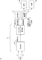
- FIG. 3 is a block diagram showing processing in the encoder 41.
- the encoder 41 includes a file I / O 51, a signal processing unit 52, an HDR (High (Dynamic Range) conversion unit 53, a transmission conversion unit 54, an SDR (Standard Dynamic Range) conversion unit 55, and an additional data calculation unit 56.
- a description will be given assuming that the video file to be displayed is a RAW data file captured by the camera.
- the file I / O 51 reads a RAW data file taken by the camera from a memory or the like.
- the file I / O extracts image data and metadata from the RAW data file.
- the image data is 10 to 16 bit fixed point data (10 to 16 bits). When the image data is 16 bits, each pixel takes a value of 16 bits (0 to 65535).
- the image data is data that has not been subjected to gamma correction.
- the metadata is data indicating the shutter speed, F value, and ISO sensitivity of the digital camera at the time of shooting. That is, the metadata corresponds to the shooting environment data in FIG.
- the image data extracted by the file I / O 51 is input to the signal processing unit 52.
- the signal processing unit 52 performs signal processing on the image data as necessary. Specifically, the signal processing unit 52 performs white balance processing and color conversion processing.
- the RGB input is multiplied by a predetermined gain value to obtain the color temperature of a certain target. That is, the signal processing unit 52 multiplies the R input by the R gain.
- the signal processing unit 52 multiplies the G input by the G gain value and multiplies the B input by the B gain value. Thereby, white balance can be corrected.
- Color conversion converts a RGB numerical value set by 3 * 3 matrix calculation into another RGB numerical value set.
- the image data processed by the signal processing unit 52 is input to the HDR conversion unit 53.
- the metadata extracted from the RAW data file is input to the HDR conversion unit 53.
- the HDR conversion unit 53 generates HDR video data based on the metadata and the image data.
- the HDR video data is 16-32 bit fixed-point data (16-32 bit fixed), and the HDR conversion unit 53 generates HDR video data corresponding to the dynamic range when the digital camera is used for shooting.
- the HDR conversion unit 53 determines brightness (cd / m 2) -gradation value reference data from the metadata. Then, the HDR conversion unit 53 converts the signal into an HDR signal based on the reference data.
- the reference data is based on the settings (F value, shutter speed, ISO) in the brightest scene, that is, the maximum brightness value of HDR data described later is defined, so that the condition with the highest brightness is used as the imaging condition. It is set using the method.
- other methods such as a method based on imaging conditions under a specified brightness (luminance) condition may be used.
- the ISO sensitivity of the input metadata is 200
- the F value is 2.8
- the shutter speed is 1/512.
- the ISO sensitivity is 400
- the F value is 4.0.
- the shutter speed is 1/64.
- the amount of light entering the camera sensor is 1 ⁇ 2 times the ISO sensitivity, twice the F value, and 1 / times the shutter speed, so that the total amount is 1 / times.
- the image data included in the RAW data file is 12 bits. Assume that R (red) pixel data is 4020 (/ 4095), G (green) pixel data is 250 (/ 4095), and B (blue) pixel data is 1920 (/ 4095).
- the HDR conversion unit 53 outputs the HDR video data to the transmission conversion unit 54.
- the transmission conversion unit 54 performs transmission conversion processing on the HDR video data. For example, the transmission conversion unit 54 performs gamma processing, gamut processing, and normalization processing.
- gamma correction is performed using a one-dimensional LUT (Look Up Table).
- gamut processing color gamut (color gamut) conversion is performed by a three-dimensional LUT.
- normalization process a process for adjusting the number of input bits to the number of output bits is performed. For example, when the input is 16 bits and the output is 12 bits, the input is multiplied by 1/16 and output. Alternatively, clipping is performed at 4095 which is the maximum value of 12 bits and output.
- the HDR video data transmitted and converted by the transmission conversion unit 54 is input to the SDR conversion unit 55.
- the SDR conversion unit 55 performs SDR conversion on the video data. That is, the SDR conversion unit 55 converts high bit HDR video data into low bit SDR video data.
- FIG. 4 is a diagram for explaining processing in the SDR converter 55.
- the horizontal axis is an input value
- the vertical axis is an output value.
- the SDR video data is an integer part having a value that is 1/4 times that of the HDR video data.
- the SDR video data is clipped to 4095.
- the SDR converter 55 outputs the SDR video data to the mapping unit 42 as output1.
- the SDR video data output1 is in a general format such as sRGB. Further, the SDR conversion unit 55 outputs the SDR video data P to the additional data calculation unit 56.
- the SDR conversion unit 55 has been described as outputting 12-bit SDR video data in FIG. 4, it may be configured to output 8-bit SDR video data. That is, the output of the SDR converter 55 can be set according to the number of bits of transmission data that can be transmitted by the interface unit 30. For example, when the interface unit 30 can transmit 8-bit transmission data, the SDR conversion unit 55 generates 8-bit SDR video data. In this case, an SDR video having a predetermined number of bits can be generated by appropriately changing the compression rate and the value to be clipped.
- the SDR video data P is input to the additional data calculation unit 56. Furthermore, the HDR video data Q from the transmission conversion unit 54 is input to the additional data calculation unit 56. The additional data calculation unit 56 generates additional data based on the HDR video data Q and the SDR video data P. The additional data is data added to the SDR video data.
- the 16-bit HDR video data is converted into 12-bit SDR video data.
- the additional data calculation unit 56 generates 12-bit additional data.
- the additional data calculation unit 56 generates additional data output2 based on the SDR video data P and the HDR video data Q.
- Output2 QP * 4 ELSE
- Output2 ((float) Q / 16384.0) * 1024.0 (output only integer part)
- output2 is an integer value (difference value) between 0 and 3.
- output2 is an integer value (gain value) of 1024 to 4095.
- the additional data calculation unit 56 generates 12-bit additional data.
- the additional data calculation unit 56 outputs the additional data to the mapping unit 42 as output2.
- the value (4095) in the conditional branch IF is the maximum value of the bit width (12 bits) of output2.
- output2 can be calculated by subtracting a value obtained by multiplying P by a compression ratio (here, 4) from Q.
- output1 (SDR video data) is 12 bits
- HDR video data is 16 bits.
- 1024 in ELSE is a gain coefficient calculated from the compression ratio by clipping, and the gain ratio is 1.0.
- the value in the above equation can be changed as appropriate according to the number of bits of the HDR video data and SDR video data. For example, when generating SDR video data based on a graph as shown in FIG. 4, the value of the equation can be appropriately changed according to the value in the graph.
- FIG. 5 is a block diagram schematically showing processing in the mapping unit 42 and the interface unit 30.
- the mapping unit 42 maps the SDR video data output1 and the additional data output2 according to the interface unit 30. As described above, the mapping unit 42 receives the SDR video data output1 and the additional data output2.
- the interface unit 30 is provided with two interfaces 30a and 30b.
- the SDR video data output1 and the additional data output2 are included in the transmission data as they are.
- the SDR video data output1 is transmitted through the interface 30a, and the additional data output2 is transmitted through the interface 30b.
- the interface unit 30 transmits the SDR video data output1 and the additional data output2 in parallel. That is, the SDR video data output1 and the additional data output2 are transmitted simultaneously.
- the two transmission data input1 and input2 transmitted via the two interfaces 30a and 30b include SDR video data output1 and additional data output2. That is, the first transmission data input1 transmitted through the interface 30a includes SDR video data output1, and the second transmission data input2 transmitted through the interface 30b includes additional data output2. Also, the two transmission data includes information regarding the frame and the pixel address. Two pieces of transmission data input 1 and input 2 transmitted via the interface unit 30 are input to the projector 10.
- FIG. 6 is a block diagram for explaining the processing of the projector 10.
- the projector 10 includes a processing unit 21, a display element 22, a D-Range control unit 23, a diaphragm 24, and a light source 25.
- the processing unit 21 includes a decoder 26 and a parameter calculation unit 27.
- the transmission data input to the projector 10 via the interface unit 30 includes SDR video data P and additional data R.
- the first transmission data includes the SDR video data P
- the second transmission data includes the additional data R.
- the decoder 26 decodes the SDR video data P and the additional data R to generate HDR video data S.
- the decoder 26 generates the HDR video data S according to the following formula.
- the HDR video data S has a value of 0 to 16383.
- P is 4095 or more, so the HDR video signal S has a value of 16384 to 65535.
- the HDR video data S is 16-bit data from 0 to 65536. Therefore, the HDR video data S equivalent to the HDR video data Q in the processing device 40 is restored.
- the decoder 26 Since information about the frame and the pixel address is added to the first transmission data and the second transmission data, the decoder 26 combines the SDR video data P and the additional data R at the same pixel address in the same frame. Thus, the HDR video data S can be generated.
- the decoder 26 decodes the SDR video data P and the additional data R to generate HDR video data S.
- the HDR video data S is 16-bit data.
- the parameter calculation unit 27 generates a display signal and a control signal based on the HDR video data. The process in the parameter calculation unit 27 will be described with reference to FIG.
- the parameter calculation unit 27 divides the HDR video data into upper bit data and lower bit data. Specifically, the parameter calculation unit 27 uses the upper 4 bits of 16-bit HDR video data as the D-range parameter. Then, the parameter calculation unit 27 generates a control signal based on the D-range parameter. Further, the parameter calculation unit 27 generates a display signal based on the lower 12 bits of the HDR video data. That is, the parameter calculation unit 27 divides into 4 bits on the MSB (Most Significant Bit) side and 12 bits on the LSB (Least Significant Bit) side. Then, the parameter calculation unit 27 generates a control signal based on the 4 bits on the MSB side, and generates a display signal based on the 12 bits on the LSB side.
- the display signal generated by the parameter calculation unit 27 is input to the display element 22.
- the display element 22 displays an image based on the display signal.
- the display element 22 includes a plurality of pixels arranged in a matrix, and each pixel is driven based on a display signal. Thereby, each pixel of RGB performs a 12-bit gradation display, and a desired image can be displayed.
- the control signal is input to the D-Range control unit 23.
- the D-Range control unit 23 controls the diaphragm 24 and the light source 25 as described above. Based on the control signal, the outputs of the diaphragm 24 and the light source 25 are controlled. Increasing the aperture of the diaphragm 24 increases the luminance, and decreasing the aperture decreases the luminance. Further, increasing the output of the light source 25 increases the luminance, and decreasing the output of the light source 25 decreases the luminance.
- the diaphragm 24 and the light source 25 serve as a luminance adjustment unit that adjusts the luminance of the displayed video according to the control signal. Of course, the luminance may be adjusted by only one of the diaphragm 24 and the light source 25.
- the control signal controls, for example, the diaphragm 24 and the light source 25 for each frame. Since the control signal is 4 bits, the D-Range control unit 23 can adjust the luminance of the frame in 16 stages.
- the parameter calculation unit 27 divides the HDR video data into upper 4 bits and lower 12 bits, but the bit positions divided by the parameter calculation unit 27 are the display element 22, the aperture 24, and the light source 25. It may be set according to the performance. For example, if each pixel of the display element 22 performs display with a gradation of 8 bits and the aperture 24 and the light source 25 can adjust the brightness with 8 bits, the parameter calculation unit 27 converts the HDR video data into the upper 8 bits and the lower 8 bits. Divide into bits.
- the D-Range control unit 23 may not divide the HDR video data. That is, in the case of the display element 22 capable of 16-bit gradation display, the processing unit 21 generates a 16-bit display signal based on the 16-bit HDR video data. In this case, the D-Range control unit 23 and the like are not necessary.
- the processing device 40 generates SDR video data and additional data to be added to the SDR video data from the HDR video data.
- the interface 30a transmits first transmission data including SDR video data
- the interface 30b transmits second transmission data including additional data. Therefore, even when the interface 30a and the interface 30b each support only the SDR video data format, the HDR video can be displayed on the projector 10 side. Therefore, HDR video can be displayed using a general-purpose interface. Thereby, versatility can be made high.
- the projector 10 includes a D-Range control unit 23 that adjusts the dynamic range based on the control signal.
- the control signal is generated according to the SDR video data and the additional data. Specifically, the control signal is generated by the data on the upper bit side of the HDR video data generated by the decoder 26. Therefore, the D-Range control unit 23 can easily adjust the luminance of the display image. Therefore, the dynamic range can be adjusted appropriately.
- FIG. 8 is a block diagram showing the configuration of the main part of the display system. In FIG. 8, the same configurations as those in FIGS. 2 and 3 are omitted.
- the projector 10 shown in FIGS. 1 and 2 is a general-purpose display that cannot display HDR video. That is, the projector 10 cannot display an image with a higher number of bits (multi-gradation) than the SDR image data.
- transmission data including SDR video data may be transmitted by one interface 30 a provided in the interface unit 30.
- SDR video data output1 is input from the SDR conversion unit 55 to the mapping unit 42, and additional data output2 is input from the additional data calculation unit 56 to the mapping unit 42.
- the mapping unit 42 outputs only the first transmission data corresponding to the SDR video data output1 to the interface 30a. That is, the interface unit 30 does not transmit the second transmission data corresponding to the additional data output2 to the projector 10.
- the SDR video data output1 is low-bit video data that can display SDR video independently.
- the SDR video data output1 is in the sRGB format.
- the interface 30a is a general-purpose interface such as HDMI as described above. Therefore, SDR video data can be transmitted. Then, the projector 10 generates a display signal from the SDR video data and displays the SDR video. That is, a low-bit video corresponding to the standard of the interface 30a is displayed. Even when there is no additional data, the projector 10 displays the SDR video based on the SDR video data output1.
- the interface 30a which is a general-purpose I / F, transmits the SDR video data output1. Therefore, versatility can be increased.
- the processing device 40 generates SDR video data and additional data added thereto, regardless of whether the projector 10 is compatible with HDR or not.
- the mapping unit 42 performs mapping so as to send appropriate transmission data according to the configuration of the interface unit 30.
- the interface unit 30 transmits transmission data including SDR video data and additional data.
- the projector 10 generates HDR video data based on the SDR video data and the additional data. Thereby, the projector 10 can display the HDR video.
- the interface unit 30 transmits transmission data including SDR video data to the projector 10 without transmitting additional data.
- the projector 10 generates a display signal based on the SDR video data.
- the encoding process on the processing device 40 side can be shared. Since there is no need to change the process according to the configuration of the interface unit 30, versatility can be enhanced. That is, the processing device 40 can be connected to either the HDR display or the general-purpose display.
- the SDR video data has a value clipped at 4095. That is, when the SDR conversion unit 55 generates SDR video data from the HDR video data, the SDR conversion unit 55 compresses the gradation value of the HDR video data by a predetermined number of bits and the compressed value of the interface 30a. It is converted to a clipped value with a value according to the number of bits. For example, as shown in FIG. 4, when the gradation value of HDR video data is 16384 to 65535, the gradation value of SDR video data is 4095. When the gradation value of the SDR video data is 4095, the projector 10 performs white display. By doing so, it is possible to display the SDR video in an appropriate range.
- FIG. 9 shows an example in which the video file is an open EXR data file.
- FIG. 9 is a block diagram illustrating a configuration of a main part of the processing device 40.
- FIG. 9 is a block diagram showing a part of the encoder 41.
- the configuration and processing after the HDR conversion unit 53 are the same as those in FIG.
- the file I / O 51 reads the open EXR data file and extracts 32-bit floating point (float) image data. Then, the file I / O 51 outputs the image data to the HDR conversion unit 53. Further, the D-range parameter indicating the absolute luminance is input to the HDR conversion unit 53 instead of the metadata in FIG.
- the D-range parameter is a parameter for setting the dynamic range to data within a certain dynamic range.
- the HDR conversion unit 53 generates HDR video data from the D-range parameter and 32-bit floating point (32-bit float) image data.
- the HDR video data is fixed-point data of 16 to 32 bits as in FIG. In this way, the same processing can be performed on CG data such as an open EXR data file. Therefore, versatility can be improved.
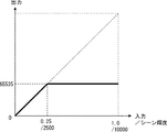
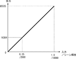
- FIG. 10 is a diagram for explaining processing in the HDR conversion unit 53 when CG data is used.
- absolute luminance can be expressed using the D-range parameter.
- the maximum luminance of the scene is set to 10000 cd / m 2 (1.0 / 32 bit float, range 0.0-1.0) as the D-range parameter.
- the maximum luminance of the projector 10 is 2500 cd / m 2 (65535/16 bits).
- the input and output change linearly.
- the maximum luminance of the scene is set to 10000 cd / m 2 (1.0 / 32 bit float, range 0.0-1.0) as the D-range parameter.
- the maximum luminance of the projector 10 is 2500 cd / m 2 (65535/16 bits). Therefore, the luminance range is compressed so that 1/4 of the input becomes the output. For example, if the input is 0.25 (2500 cd / m 2 ), the gradation value of the output HDR video data is 16384.
- the gradation value of the HDR video data to be output is 65535 (maximum value).
- the luminance range is compressed by the ratio of the maximum luminance of the D-range parameter and the maximum luminance of the projector 10.
- FIG. 12 Another process for the HDR conversion unit 53 to generate the HDR video data will be described with reference to FIG. In FIG. 12, processing in which the processing in FIG. 10 and the processing in FIG. 11 are combined is performed. Specifically, the absolute luminance is matched up to the specified value of 2000 cd / m 2 as shown in FIG. For luminance above 2000 cd / m 2 , the luminance range is compressed. Therefore, as shown in FIG. 12, HDR video data can be generated with two straight lines having different inclinations. Alternatively, it is possible to generate HDR video data using a non-linear function on the compressed side.
- the gradation value of the HDR video data to be output is 52429.
- the relationship between the input and the output matches that in FIG.
- the HDR conversion unit 53 may generate the HDR video data by other processing.
- FIG. 13 is a diagram illustrating processing in the interface unit 30 and the mapping unit 42 that can transmit a 3D image. Note that the configuration and processing other than the interface unit 30 and the mapping unit 42 are the same as those described above, and thus description thereof is omitted.
- the interface 30a of the interface unit 30 can transmit a 3D image format.
- the 3D image format is a side-by-side format including a left image and a right image as shown in FIG. That is, the 3D image is generated by combining the left image and the right image, and the interface unit 30 transmits the 3D image in the side-by-side format.
- the 3D image is an SDR image having a lower bit number than the HDR image.
- the resolution of the 3D image and the resolution of the HDR video are the same.
- the left image and the right image have the same resolution as the HDR image.
- the mapping unit 42 assigns the SDR video data output1 to one of the left image and the right image, and assigns the additional data output2 to the other of the left image and the right image.
- the mapping unit 42 assigns SDR video data output1 to the left image and assigns additional data output2 to the right image.
- the mapping unit 42 can be a 3D encoder.
- the interface unit 30 transmits the SDR video data output1 assigned to the left image and the additional data output2 assigned to the right image as one transmission data. Therefore, SDR video data output1 and additional data output2 are transmitted simultaneously.
- the pixel address of the left image corresponding to the pixel address (x, y) of the 3D image is (x L , y L ), and the pixel address of the right image is (x R , y R ).
- the projector 10 uses the HDR video data assigned to the pixel address (x L , y L ) in the 3D image and the additional data assigned to the pixel address (x R , y R ) to use the pixel address (x , Y) Generate HDR video data.
- the processing unit of the projector 10 generates the HDR video data of the pixel address using the same pixel address of the left image and the right image.
- HDR video can be displayed. That is, if there is at least one interface 30a capable of displaying a 3D image, the projector 10 can display the HDR video. Therefore, versatility can be further increased.
- FIG. 14 is a diagram for explaining processing when the interface unit 30 capable of transmitting a high-resolution image format is provided.
- FIG. 14 is a diagram illustrating processing in the interface unit 30 and the mapping unit 42 that can transmit a high-resolution image. Note that the configuration and processing other than the interface unit 30 and the mapping unit 42 are the same as those described above, and thus description thereof is omitted.
- the high-resolution image is 4K resolution (horizontal 4096 ⁇ vertical 2160) and the resolution of the HDR video is 2K (horizontal 2048 ⁇ vertical 1080).
- the resolution of the projector 10 is 2K.
- the interface 30a of the interface unit 30 can transmit an image with a resolution of 4K. That is, the interface 30a can transmit transmission data in a high-resolution format that is higher than the resolution of the projector 10.
- SDR video data output1 and additional data output2 are distributed and transmitted to different pixel addresses of the 4K image.
- the high resolution image is divided into four equal parts in the upper left, upper right, lower left, and lower right.
- each of the four regions 61 to 64 has the number of pixels for 2K images.
- the mapping unit 42 assigns SDR video data output1 to the upper left area 61 of the high resolution image. Further, the mapping unit 42 assigns additional data output2 to the upper right area 62, lower right area 63, and lower left area 64 of the high resolution image. In FIG. 14, additional data output2-1 is allocated to the upper right area 62. Additional data output2-2 is assigned to the lower left area 63. Additional data output2-3 is assigned to the lower right area 64.
- the interface unit 30 has an interface 30a capable of transmitting 4K images.
- the interface 30a transmits data for all pixels of the 4K image. Therefore, the interface 30a can transmit the SDR video data output1 and the additional data output2-1 to output2-3. In this case, SDR video data output1 and additional data output2 are transmitted alternately.
- the projector 10 decodes the bit video data output1 and the additional data output2-1 to output2-3 distributed at different pixel addresses to generate HDR video data.
- the processing unit of the projector 10 generates HDR video data using the SDR video data output1 of the corresponding pixel address in the four divided areas and the additional data output2-1 to output2-3.
- the SDR video data of the pixel address (1, 1), the additional data output 2-1 of the pixel address (2001, 1), the additional data output 2-2 of the pixel address (1, 1001), and the pixel address (2001, 1001) The HDR video data of the pixel address (1, 1) is generated using the additional data output2-3. In this way, video data for one pixel in the HDR video is generated using data for four pixels in the 4K image.
- the additional data can have a larger number of bits.
- the additional data can be three times as many bits as the SDR video data.
- the amount that can be handled as difference data can be made larger than in the case of 2-port output. (In the case of 2K input and 4K output, it is possible to transfer the difference value data three times that of the 2K2 port.) Therefore, the bit width of the difference value input (output2) can be increased.
- the SDR video data output1 and the additional data output2 may have the same bit width.
- the mapping unit 42 allocates the bit video data output1 to half of the 4K image, and allocates the additional data output2 to the other half. As a result, more bits of HDR video data can be transmitted.
- HDR video can be displayed. That is, if there is an interface 30a capable of transmitting a high resolution image format, the projector 10 can display a low resolution HDR video. Therefore, versatility can be further increased.
- the processing device 40 generates transmission data including SDR video data having a bit number smaller than the gradation bit number of the HDR video data based on the HDR video data. Further, the processing device 40 generates SDR video data and additional data to be added to the SDR video data from the HDR video data.
- the interface unit 30 transmits transmission data.
- the projector 10 generates a display signal based on the transmission data transmitted via the interface unit 30, and displays an image based on the display signal. Thereby, versatility can be made high.
- the process of generating SDR video data and additional data from HDR video data is the same.
- Processing in the encoder 41 can be shared. Therefore, versatility can be further improved. That is, since it is only necessary to change the process in the mapping unit 42, the process and configuration can be simplified.
- FIG. 15 is a block diagram showing the configuration of the projector 10 for performing this control example.
- the basic configuration of the projector 10 shown in FIG. 15 is the same as that in FIG.
- the method for generating the HDR video data S from the SDR video data P and R is the same as described above, and thus the description thereof is omitted.
- At least one of the diaphragm 24 and the light source 25 functions as a light control device.
- the light source 25 is a light source that irradiates the entire surface of the display element 22 simultaneously
- the diaphragm 24 cannot be dimmed in pixel units even if the aperture ratio is changed. That is, the diaphragm 24 and the light source 25 cannot be locally dimmed, and thus are controlled for each frame. That is, the aperture ratio of the diaphragm 24 changes in units of frames. Therefore, the aperture ratio of the diaphragm 24 is constant within one frame.
- the parameter calculation unit 27 generates a control signal corresponding to the resolution of the light control device.
- the diaphragm 24 functions as a dimming device having a 4-bit resolution
- the aperture 24 can control the aperture ratio in 16 steps.
- the diaphragm 24 controls the aperture ratio based on a 4-bit control signal.
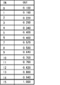
- FIG. 16 is a table showing the relationship between the control signal and the aperture ratio (injection light quantity) of the diaphragm 24.
- the aperture ratio (OUT) of the diaphragm 24 changes according to the value of the 4-bit control signal (IN).
- the value of the control signal is 15, the aperture ratio of the diaphragm 24 is maximized.
- the maximum value of the aperture ratio of the diaphragm 24 is normalized as 1.
- the aperture ratio of the diaphragm 24 decreases.
- the aperture ratio of the diaphragm is 0.1. That is, the brightness when the value of the control signal is 15 is 10 times that when the value of the control signal is 0.
- the control signal can be, for example, the upper 4 bits of the HDR video data S that takes the maximum value within one frame. That is, the value of the upper 4 bits of the pixel having the maximum value is the control signal.
- the control signal may be the upper 4 bits of the average value of the HDR video data S within one frame.
- the upper 4 bits of the local average value may be used as the control signal.
- the control signal is determined by the maximum value or the average value. Note that the control signal determination method depends on the display application.
- the display signal of each pixel is set.
- the parameter calculation unit 27 converts the 16-bit HDR video data S into a 12-bit display signal (4096 gradation values) for each pixel.
- a 12-bit display signal is generated based on the lower 12 bits of 16-bit HDR video data S. Accordingly, the display element 22 modulates light for each pixel based on the 12-bit gradation value of the 12-bit display signal.
- the parameter calculation unit 27 generates a control signal and a display signal based on the HDR video data S. Since the 16-bit RGB display element 22 can control the drive of 4096 gradations (12 bits) for the HDR video data S, the display signal output to the display element 22 is also 12 bits.
- the horizontal axis represents the HDR video data S
- the vertical axis represents the brightness (relative value) of the display image.
- the relationship between the HDR video data S and the brightness is indicated by a straight line depending on the value of the control signal. Specifically, control signal values (0 to 4, 14, and 15 in FIG. 17) are attached to the respective straight lines.
- the value of the control signal corresponds to the 16-bit gradation of the HDR video data S increased by 1 for every 4096 gradations.
- the control signal is determined based on the maximum value of the HDR video data in one frame.
- the maximum value of the HDR video data S is 0 to 4095
- the value of the control signal is 0, and when the maximum value of the HDR video data S is 4096 to 8191, the value of the control signal is 1.
- 0 to the maximum brightness is expressed with 12-bit gradation.
- the value of the control signal is 0, 0 to 4095 are assigned to 12 bits, and when the value of the control signal is 1, 0 to 8191 are assigned to 12 bits.
- the diaphragm 24 is dimmed every frame, the gradation of all the pixels in one frame period is expressed by one straight line based on the value of one control signal.
- the parameter calculation unit 27 generates a display signal and a control signal by the following calculation.
- the parameter calculation unit 27 acquires the brightness data B1 in the right column of FIG. 16 from the MSB 4 bits of the HDR video data S used as a control signal.
- the parameter calculation unit 27 calculates the ratio (B2 / B1) to the brightness to be controlled by comparing with the MSB 4-bit brightness data B2 of each pixel data.
- the parameter calculation unit 27 determines the display signal by multiplying the LSB 12-bit signal of the HDR video data S by the calculated ratio value.
- the HDR video data S is 11111111111111111111.
- the brightness B1 is 1.0 in the pixel 1
- the display signals of the pixels 1 and 2 are calculated by extracting and calculating the lower 13 bits and converting them to 12 bits.
- Such calculation corresponds to the process of reshaping the 12-minute gradation in FIG.
- the ratio (contrast) between the maximum light amount and the minimum light amount can be increased by performing the D-range control with the light source 25 instead of the diaphragm 24. Furthermore, instead of D-range control for each frame, D-range control for each area obtained by dividing one frame into a plurality of areas can be performed. Further, the number of bits of the control signal is not limited to 4 bits. The number of bits of the control signal may be set according to the performance of the diaphragm 24 and the light source 25.
- the aperture ratio of the diaphragm 24 with respect to the control signal is linear, but it may be non-linear. Control in the case where dimming by the dimming device is nonlinear with respect to the signal will be described with reference to FIG. In the case of non-linearity, a display signal is generated using a look-up table (LUT).
- LUT look-up table
- the parameter calculation unit 27 first generates a control signal according to the upper 4 bits of the HDR video data S. Then, the parameter calculation unit 27 outputs the control signal to the D-Range control unit 23 as described above. Since the control by the D-Range control unit 23 is the same as described above, the description thereof is omitted.
- the parameter calculation unit 27 outputs a control signal to the LUT selection unit 28.
- the LUT selection unit 28 outputs a selection signal for selecting an LUT according to the value of the control signal.
- the number of LUTs corresponding to the number of bits of the control signal is stored in advance in a memory or the like. For example, when the control signal is 4 bits, the LUT selection unit 28 stores 16 LUTs. Then, the LUT selection unit 28 selects an LUT corresponding to the value of the control signal from a plurality of LUTs stored in advance.
- the HDR video data S and the display signal are associated with the LUT.
- the LUT calculation unit 29 generates a 12-bit display signal based on the HDR video data S. That is, the LUT calculation unit 29 refers to the selected LUT and converts the value of the HDR video data S into a 12-bit value. Thereby, a 12-bit display signal is generated.
- control signal can have a number of bits corresponding to the resolution of the dimming device. For example, when the resolution of the light control device is 1 bit, for example, when the diaphragm 24 and the light source 25 perform light control in two stages, the control signal can also be 1 bit. Moreover, you may use both the aperture_diaphragm
- the LUT when displaying on a general-purpose display without a dimming device, the LUT is fixed. That is, regardless of the value of the HDR video data S, the LUT selection unit 281 selects one LUT.
- the LUT is tone mapping data for converting the HDR video data S into SDR video data.
- a display signal corresponding to the number of bits of the display element 22 may be generated.
- the above processing may be performed by the projector 10 or the processing device 40.
- the processing device 40 performs, the processing device 40 performs processing according to the performance of the connected projector 10.
- the model of the projector 10 is specified by using EDID (Extended Display Identified Data) output from the projector 10. Then, the number of bits of the display signal and the control signal is determined according to the specified model.
- the processing device 40 may transmit the control signal and the display signal to the projector 10 via the two ports.
- FIG. 19 is a diagram illustrating an overall configuration of the display system 100.
- a liquid crystal panel 15 is added to the display system 100 of FIG. That is, light from the projection unit 11 is projected onto the screen 14 via the liquid crystal panel 15. Since the configuration other than the liquid crystal panel 15 and the basic control are the same as described above, the description thereof is omitted.
- the liquid crystal panel 15 functions as a dimming device capable of local dimming.
- the liquid crystal panel 15 has a plurality of pixels.
- the liquid crystal panel 15 controls the amount of light that passes from the projection unit 11 to the screen 14 for each pixel. Further, the liquid crystal panel 15 controls the amount of transmitted light for each pixel according to the control signal.
- the pixels of the liquid crystal panel 15 correspond to the pixels of the projection unit 11. Therefore, the liquid crystal panel 15 controls the gradation of the pixels according to the control signal, so that the dynamic range can be widened.
- the liquid crystal panel 15 does not correspond to RGB color display.
- the liquid crystal panel 15 performs luminance modulation according to the luminance signal (Y), not the RGB signal.
- Y luminance signal
- a transmissive liquid crystal panel 15 is used, but a reflective liquid crystal panel 15 may be used as disclosed in JP-A-2007-310045.
- the decoder 26 outputs the HDR video data S to the first conversion unit 71.
- the HDR video data S is a 16-bit RGB signal.
- the first converter 71 converts the HDR video data S into a luminance signal (Y) and a color difference signal (CbCr). Since the HDR video data S is 16 bits, the luminance signal (Y) and the color difference signal (CbCr) are also 16 bits.
- the first converter 71 outputs a 16-bit luminance signal (Y) and a color difference signal (CbCr) to the parameter calculator 27.
- the parameter calculation unit 27 generates a control signal according to the luminance signal (Y).
- the control signal is generated in accordance with the MSB side bit of the luminance signal (Y). That is, when the control signal is 4 bits, the control signal is created according to 4 bits on the MSB side of the luminance signal (Y).
- the number of bits of the control signal is a value corresponding to the number of gradations of the liquid crystal panel 15.
- the parameter calculation unit 27 outputs a control signal to the D-Range control unit 23.
- the D-Range control unit 23 outputs a drive signal for driving each pixel of the liquid crystal panel 15 based on the control signal. Thereby, each pixel of the liquid crystal panel 15 is driven. That is, the liquid crystal panel 15 performs luminance modulation according to the luminance signal (Y). Therefore, the liquid crystal panel 15 controls the luminance (gradation) of each pixel based on the drive signal.
- the parameter calculation unit 27 outputs a 12-bit luminance signal (Y) and a 16-bit color difference signal (CbCr) to the second conversion unit 72.
- the second converter 72 converts the luminance signal (Y) and the color difference signal (CbCr) into RGB display signals. That is, the second conversion unit 72 generates a display signal based on the luminance signal (Y) and the color difference signal (CbCr).
- the luminance signal (Y) output from the parameter calculation unit 27 is 12 bits in accordance with the number of bits of the display signal.
- the display element 22 performs color image display according to a 12-bit display signal.
- the projection unit 11 of the display element 22 projects an image on the screen 14 via the liquid crystal panel 15.
- the liquid crystal panel 15 performs gradation control as described above. Thereby, the light amount of the projection light from the projection unit 11 is controlled in the liquid crystal panel 15. Therefore, the dynamic range can be widened. Further, by setting the liquid crystal panel 15 to have more gradations, an image can be displayed more precisely.
- the display signal may be a 12-bit RGB signal and the liquid crystal panel 15 may be an 8-bit luminance signal (Y). In this case, the HDR video data S may be expressed using a total of 20 bits.
- the luminance signal (Y) may be linear or may have a gamma value.
- Gamma correction when the liquid crystal panel 15 and the projection unit 11 are used will be described with reference to FIG.
- the horizontal axis represents the input value
- the vertical axis represents the light output (luminance).
- description will be made assuming that the gamma value of the projector 10 is 2.2.
- the input HDR video data S is divided into two.
- the gamma characteristic of the projection unit 11 is 1.1
- the gamma characteristic of the liquid crystal panel 15 is 1.1.
- a display signal input to the projection unit 11 and a drive signal input to the liquid crystal panel 15 are generated by adjusting the gamma value.
- a lookup table can be used to generate the display signal and the drive signal.
- the gamma characteristics of the projection unit 11 and the liquid crystal panel 15 are not limited to these values.
- the sum of the gamma value in the first output characteristic and the gamma value in the second output characteristic may be equal to the gamma value of the projector 10.
- the parameter calculation unit 27 may generate the drive signal and the display signal in consideration of the gamma characteristic.
- FIG. 22 shows an example when the modulation of the liquid crystal panel 15 is limited to a predetermined range on the dark side.
- the gamma value of the gamma characteristic of the projector 10 when the gamma value of the gamma characteristic of the projector 10 is defined by 2.2, the gamma value of the output characteristic of the projection lens 12 is 2.2 (however, the input is 0.25 or less). In this example, the gamma value is 1.2), and the gamma value of the liquid crystal panel 15 is 1. Further, in the gamma characteristic of the liquid crystal panel 15, the light output amount is uniformly maximized when the input value is 0.25 or more. Thus, the output characteristics of the liquid crystal panel 15 may be fixed to the maximum value when the input value is equal to or greater than a predetermined value.
- all the gradations of the liquid crystal panel 15 can be assigned to a gamma region having an input value of 0.25 or less, and the gradation on the dark side can be expressed with a finer gradation.
- Each embodiment and example can be combined as appropriate.
- Non-transitory computer readable media include various types of tangible storage media.
- Examples of non-transitory computer-readable media include magnetic recording media (for example, flexible disks, magnetic tapes, hard disk drives), magneto-optical recording media (for example, magneto-optical disks), CD-ROMs (Read Only Memory), CD-Rs, CD-R / W, semiconductor memory (for example, mask ROM, PROM (Programmable ROM), EPROM (Erasable PROM), flash ROM, RAM (Random Access Memory)).
- the program may be supplied to a computer by various types of temporary computer readable media.
- Examples of transitory computer readable media include electrical signals, optical signals, and electromagnetic waves.
- the temporary computer-readable medium can supply the program to the computer via a wired communication path such as an electric wire and an optical fiber, or a wireless communication path.
- the present invention can be applied to a display system that displays an image.
Landscapes
- Engineering & Computer Science (AREA)
- Multimedia (AREA)
- Signal Processing (AREA)
- Controls And Circuits For Display Device (AREA)
Abstract
汎用性の高い表示システム、処理装置、表示装置、処理方法、及びプログラムを提供する。 本実施の形態にかかる表示システム(100)は、HDR映像データに基づいて、HDR映像データの階調ビット数よりも小さいビット数のSDR映像データを含む伝送データを生成する処理装置(40)と、伝送データを伝送するインターフェース部(30)と、インターフェース部(30)を介して伝送された伝送データに基づいて表示信号を生成し、表示信号に基づいて映像を表示するプロジェクタ(10)と、を備えている。処理装置(40)は、HDR映像データから、SDR映像データ、及びSDR映像データに付加される付加データを生成する。
Description
本発明は、表示システム、処理装置、表示装置、処理方法、及びプログラムに関する。
近年、高ダイナミックレンジ(HDR: High Dynamic Range)映像を表示する表示装置が開発されている。なお、ダイナミックレンジとは、最も明るい箇所と最も暗い箇所との比である。通常の液晶ディスプレイでは、輝度が100cd/m2、ダイナミックレンジ(コントラスト比)が1000:1程度であるところ、HDRディスプレイでは例えば、輝度が1000cd/m2、ダイナミックレンジが50000:1となる。
そのため、通常の表示システムでは、RGBそれぞれ8ビット(256階調)であるところ、HDR映像表示システムでは、8ビットよりも高ビットの映像データを取り扱う必要がある。50000:1のレンジを256階調で表現するには、階調不足となるためである。例えば、HDRカメラの映像やOpen-EXR等のCG(Computer Graphics)映像では、16ビットや32ビット等の映像データを取り扱う必要が生じる。
このようなHDR映像を表示するためには、HDR対応のディスプレイ(表示装置)が必要となる。さらに、HDR対応のディスプレイに高ビットの映像データを伝送する必要がある。
しかしながら、パソコンやカメラ等からディスプレイにデータを伝送する場合、入出力インターフェースが制限される。例えば、通常のパソコンでは、HDMI(登録商標)(High Definition Multimedia Interface)、DisplayPort、DVI(Digital Visual Interface)、SDI(Serial Digital Interface)等の汎用インターフェースでデータをディスプレイに伝送している。しかしながら、汎用インターフェースを用いた場合、インターフェースの規格よりも高いビット数のデータを伝送することができないという問題点がある。
本発明は上記の点に鑑みなされたもので、汎用性の高い表示システム、表示装置、処理装置、方法、及び、プログラムを提供することを目的とする。
本実施形態にかかる表示システムは、高ビット映像データに基づいて、前記高ビット映像データの階調ビット数よりも小さいビット数の低ビット映像データを含む伝送データを生成する処理装置と、前記伝送データを伝送するインターフェース部と、前記インターフェース部を介して伝送された前記伝送データに基づいて表示信号を生成し、前記表示信号に基づいて映像を表示する表示装置と、を備え、前記処理装置は、前記高ビット映像データから、前記低ビット映像データ、及び前記低ビット映像データに付加される付加データを生成するものである。
本実施形態にかかる処理装置は、高ビット映像データに基づいて、前記高ビット映像データの階調ビット数よりも小さいビット数の低ビット映像データと、前記低ビット映像データに付加される付加データを生成するエンコーダと、前記付加データ、及び前記低ビット映像データを伝送するインターフェース部と、を備えたものである。
本実施形態にかかる表示装置は、高ビット映像データを上位ビット側のデータと、下位ビット側のデータに分割する処理部と、複数の画素を有し、前記下位ビット側のデータに基づく表示信号によって各画素を駆動する表示素子と、前記上位ビット側のデータに基づく制御信号によって、輝度を調整する輝度調整部と、を備えたものである。
本実施形態にかかる表示方法は、処理装置が、高ビット映像データに基づいて、前記高ビット映像データの階調ビット数よりも小さいビット数の低ビット映像データを含む伝送データを生成するステップと、インターフェース部を介して前記伝送データを表示装置に伝送するステップと、前記表示装置が前記インターフェース部を介して伝送された前記伝送データに基づいて表示信号を生成し、前記表示信号に基づいて映像を表示するステップと、を備え、前記処理装置は、前記高ビット映像データから、前記低ビット映像データ、及び前記低ビット映像データに付加される付加データを生成するものである。
本実施形態にかかるプログラムは、高ビット映像データに基づいて、前記高ビット映像データの階調ビット数よりも小さいビット数の低ビット映像データと、前記低ビット映像データに付加される付加データを生成するステップと、前記付加データ、及び前記低ビット映像データを伝送データとしてインターフェース部から出力させるステップとを、コンピュータに対して実行させるものである。
本実施形態によれば、汎用性の高い表示システム、表示装置、処理装置、表示方法、及びプログラムを提供できる。
〈HDRディスプレイ〉
本実施の形態にかかる表示システムは、HDRの映像を表示する表示システムである。図1に、表示システムの全体構成を示す。表示システムは、プロジェクタ10と、インターフェース部30と、処理装置40とを備えている。
本実施の形態にかかる表示システムは、HDRの映像を表示する表示システムである。図1に、表示システムの全体構成を示す。表示システムは、プロジェクタ10と、インターフェース部30と、処理装置40とを備えている。
プロジェクタ10は、HDR対応のディスプレイ(表示装置)であり、動画又は静止画の映像を表示する。例えば、プロジェクタ10は、16ビットのRGBの表示信号に基づいて、映像を表示する。すなわち、プロジェクタ10のRGBの各画素では、0~65535の階調表示が行われる。なお、以下の説明において、データ、又は信号のビット数は、RGBの各画素の階調値を示す値となる。
プロジェクタ10は、背面投射型のプロジェクタ(リアプロジェクタ)であり、投射部11と、投射レンズ12と、ミラー13と、スクリーン14とを備えている。なお、本実施の形態では、HDR対応のディスプレイが背面投射型のプロジェクタ10であるとして説明するが、反射型のプロジェクタ、あるいは、プラズマディスプレイ、液晶ディスプレイ、有機EL(Electroluminescent)ディスプレイなどの他のディスプレイ(表示装置)であってもよい。
投射部11は、スクリーン14上に映像を投射するため、表示信号に基づいて投射光を生成する。例えば、投射部11は、光源、及び空間変調器を備えている。光源は、ランプ又はLED(Light Emitting Diode)などである。空間変調器はLCOS(Liquid Crystal On Silicon)パネル、透過型液晶パネル、又は、DMD(Digital Mirror Device)などである。投射部11は、光源からの光を空間変調器で変調する。そして、空間変調器で変調された光が、投射レンズ12から投射光として出射される。投射レンズ12からの投射光は、ミラー13でスクリーン14の方向に反射されている。投影レンズ12は、複数のレンズを有しており、投射部11からの映像をスクリーン14上に拡大投影する。
処理装置40は、例えばパーソナルコンピュータ(PC)等であり、CPU(Central Processing Unit)、メモリ、グラフィックカード、キーボード、マウス、入出力ポート(入出力I/F)等を備えている。映像入出力に関する入出力ポートは、例えば、HDMI(High Definition Multimedia Interface)、DisplayPort、DVI(Digital Visual Interface)、SDI(Serial Digital Interface)等である。処理装置40は、メモリやハードディスクなどに、映像ファイルを格納している。あるいは、処理装置40は、デジタルカメラであってもよい。処理装置40がデジタルカメラである場合、処理装置40は、撮像素子で取得した映像に対して所定の処理を行う。
インターフェース部30は、処理装置40とプロジェクタ10との間にインターフェースを有している。すなわち、インターフェース部30を介して、処理装置40とプロジェクタ10との間でデータが伝送される。具体的には、インターフェース部30は処理装置40の出力ポート、プロジェクタ10の入力ポート、及び、出力ポートと入力ポートを接続するAV(Audio Visual)ケーブル等を備えている。
処理装置40は、インターフェース部30に伝送される伝送データを生成する。具体的には、処理装置40は、メモリ等に映像ファイルを格納している。処理装置40は、映像ファイルに基づいて、インターフェース部30のインターフェースの規格に準拠した伝送データを生成する。そして、処理装置40は、インターフェース部30を介して、プロジェクタ10に伝送データを出力する。すなわち、インターフェース部30は、処理装置40で生成された伝送データをプロジェクタ10に伝送する。プロジェクタ10は、入力された伝送データに基づいて、表示信号を生成する。そして、プロジェクタ10は、表示信号に基づいて、映像を表示する。
ここで、処理装置40のグラフィックカード、又はインターフェース部30のインターフェースによって、インターフェース部30で伝送されるビット数(ビット幅)が制限される。例えば、HDMI(High Definition Multimedia Interface)、DisplayPort、DVI(Digital Visual Interface)、SDI(Serial Digital Interface)等の汎用インターフェースでは、8ビット(256階調)又は12ビット(4096階調)の低ビットデータまでしか伝送することができない場合がある。一方、プロジェクタ10で表示することができるHDR映像は16ビット、又は32ビットの高ビットデータである。そのため、本実施形態では処理装置40がインターフェース部30のインターフェース規格に準拠した低ビットの映像データ(表示階調データ)を含む伝送データを生成している。
以下の説明において、インターフェース部30で伝送することができるビット数(ビット幅)のデータを低ビットのデータ(例えば8ビット又は12ビット)とし、低ビットデータより高いビット数(ビット幅)のデータを高ビットのデータ(例えば、16ビット又は32ビット)として説明を行う。すなわち、インターフェース部30が8ビットのデータを伝送可能な場合、8ビットデータは、低ビットのデータとなり、8ビットよりも大きいデータは、高ビットのデータとなる。また、インターフェース部30が12ビットのデータを伝送可能な場合、12ビットデータは、低ビットのデータとなり、12ビットよりも大きいデータは、高ビットのデータとなる。プロジェクタ10は高ビットの映像、すなわちHDR映像を表示する。よって、プロジェクタ10は広いダイナミックレンジでキャプチャされたカメラ映像やHDRで作成されたCG映像を正しく表示することができる。
図2に表示システムにおける処理を模式化したブロック図を示す。処理装置40とプロジェクタ10とは、2つのインターフェース30a、30bを介して接続されている。処理装置40は、エンコーダ41とマッピング部42を備えている。処理装置40には、例えば、映像ファイルに含まれる画像データ、及び撮影環境データが入力される。なお、処理装置40は、画像データ、及び撮影環境データをメモリ等に格納して、メモリから読み出すようにしてもよい。
画像データは、16bit TIFFや、Open EXR等のフォーマットで記録されている。画像データは、汎用AVインターフェースのサポート外のフォーマットでメモリ等に格納されている。画像データは、例えば、16ビット又は32ビットの高ビットデータである。画像データは、画素毎に、16ビット階調又は32ビット階調のデータを含んでいる。例えば16ビット階調のデータを8ビット階調にすることで、階調値が256分の1に圧縮されてしまい、階調性が悪化する。したがって、汎用のインターフェース30a、又はインターフェース30bを介してそのまま伝送すると、画質が劣化してしまう。撮影環境データは、撮影環境を示すデータである。例えば、画像データがデジタルカメラで取得したデータである場合、撮影環境データは、デジタルカメラのシャッタスピード、F値、ISO感度等を示すメタデータである。
エンコーダ41は、撮影環境データ、及び画像データをエンコードして、伝送データを生成する。より具体的には、エンコーダ41は、撮影環境データ、及び画像データに基づいて、一つの映像データを生成する。映像データには、高ビットの階調データが含まれている。すなわち、映像データに含まれる階調データは、高ビットのデータである。さらに、エンコーダ41は、高ビットの映像データに基づいて、インターフェース部30の規格に応じた伝送データを生成する。伝送データは、インターフェース部30で伝送可能な低ビットデータである。
マッピング部42は、インターフェース部30のインターフェースに応じて、マッピング処理を行う。なお、マッピング部42の処理については後述する。そして、伝送データがインターフェース部30を介して伝送される。
本実施の形態では、インターフェース部30が2つのインターフェース30a、30bを有している。インターフェース30a、30bはそれぞれ映像、及び音声を伝送可能なAVインターフェースである。例えば、インターフェース30aは、HDMIであり、インターフェース30bは、DVIである。このように、2つのインターフェース30a、30bを、異なる規格とすることが可能である。また、インターフェース30a、30bはそれぞれHDMI、DisplayPort,DVI、及びSDI等のいずれか1つであればよい。もちろん、インターフェース30a、30bは、HDMI、DisplayPort,DVI、又はSDI以外の汎用インターフェースであってもよい。すなわち、インターフェース30a、30bはそれぞれ低ビットのビデオデータを送信する汎用インターフェースである。
また、インターフェース30aとインターフェース30bは同じ規格であってもよい。例えば、処理装置40にHDMI出力端子が2つある場合、一方のHDMI出力端子がインターフェース30aとなり、他方のHDMI出力端子がインターフェース30bとなってもよい。この場合、もちろん、プロジェクタ10にも2つのHDMI入力端子が設けられている。インターフェース30a、30bは、物理的に2つのインターフェースであれば、同じ規格であっても異なる規格であってもよい。換言すると、インターフェース部30はプロジェクタ10と処理装置40とを接続する2本のAVケーブルを有している。
プロジェクタ10は、処理部21、表示素子22、D-Range制御部23、絞り(アパーチャ)24、及び光源25を備えている。処理部21は、プロセッサやメモリ等を備えており、伝送データに対して所定の処理を行う。処理部21は、インターフェース部30を介して伝送された2つの伝送データに基づいて、表示信号、及び制御信号を生成する。
処理部21で生成された表示信号は、表示素子22に出力される。表示素子22は、投射部11に設けられた空間変調器などを有しており、表示信号に基づいて光を変調する。すなわち、表示素子22は、複数の画素を備えており、表示信号に基づいて、各画素を駆動する。これにより、プロジェクタ10は、所望の映像を表示する。
さらに、処理部21で生成された制御信号は、D-Range制御部23に入力される。D-Range制御部23は、制御信号に基づいて、プロジェクタ10のダイナミックレンジを制御する。具体的には、D-Range制御部23は、絞り24、及び光源25を制御する。例えば、D-Range制御部23は、投射レンズ12に設けられている絞り24の開口の大きさを制御する。絞り24は、スクリーンにおける輝度を動画像の1フレーム単位で制御する。
また、D-Range制御部23は、投射部11に設けられている光源25の発光量を制御する。光源25は、スクリーンにおける輝度を動画像の1フレーム単位で制御する。なお、表示装置としてプロジェクタ10の代わりに液晶ディスプレイなどを用いた場合、D-Range制御部23はローカルディミング的に光源25の光量を制御してもよい。この場合、投射部11には独立に制御可能な複数の光源25が設けられている。そして、1フレームの映像の一部を高輝度とし、他の一部を低輝度とする。D-Range制御部23が制御信号に基づいて、絞り24、及び光源25を制御することにより、所望の輝度で映像が表示される。よって、より高画質で映像を表示することができる。なお、D-Range制御部23は、絞り24、光源25の一方のみを制御するようにしてもよい。
次に、処理装置40のエンコーダ41での処理について図3を用いて説明する。図3は、エンコーダ41での処理を示すブロック図である。エンコーダ41は、ファイルI/O51、信号処理部52、HDR(High Dynamic Range)変換部53、伝送変換部54、SDR(Standard Dynamic Range)変換部55、及び付加データ算出部56を備えている。ここでは、表示する映像ファイルがカメラで撮影したRAWデータファイルとなっているとして説明する。
ファイルI/O51は、カメラが撮影したRAWデータファイルをメモリ等から読み出す。ファイルI/Oは、RAWデータファイルから画像データ、及びメタデータを抽出する。なお、画像データは、10~16ビットの固定小数点方式のデータ(10~16bit fixed)である。画像データが16ビットの場合、各画素は16ビット(0~65535)の値を取る。また、画像データは、ガンマ補正が行われていないデータである。メタデータは、撮影時のデジタルカメラのシャッタスピード、F値、ISO感度を示すデータである。すなわち、メタデータは、図2の撮影環境データに相当する。
ファイルI/O51で抽出された画像データは、信号処理部52に入力される。信号処理部52は必要に応じて、画像データに信号処理を施す。具体的には、信号処理部52は、ホワイトバランス(White balance)処理、色変換(color conversion)処理を行う。ホワイトバランス処理では、あるターゲットの色温度とするために、RGBの入力に、所定のゲイン値を乗じる。すなわち、信号処理部52はRの入力にRのゲインを乗じる。同様に、信号処理部52はGの入力にGのゲイン値を乗じ、Bの入力にBのゲイン値を乗じる。これにより、ホワイトバランスを補正することができる。色変換は、3*3のマトリクス計算によるRGBの数値セットをRGBの別の数値セットに変換する。
信号処理部52での処理が施された画像データは、HDR変換部53に入力される。また、RAWデータファイルから抽出されたメタデータは、HDR変換部53に入力される。HDR変換部53は、メタデータ、及び画像データに基づいて、HDRの映像データを生成する。HDR映像データは16~32ビットの固定小数点方式のデータ(16-32bit fixed)である、HDR変換部53は、デジタルカメラで撮影した時のダイナミックレンジに対応するHDR映像データを生成する。
例えば、HDR変換部53は、メタデータから明るさ(cd/m2)-階調値のリファレンスデータを決める。そして、HDR変換部53は、リファレンスデータに基づいて、HDR信号に変換する。リファレンスデータは、一番明るいシーンでの設定(F値、シャッタスピード、ISO)を基準する、つまり、後述のHDRデータの最大輝度値を規定するため、撮像条件として輝度が一番高い条件を基準とする方法を用いて設定される。また、キャリブレーションされたカメラであれば、規定された明るさ(輝度)の条件下での撮像条件を基準にする、等の他の方法を用いてもよい。
入力されたメタデータのISO感度が200、F値が2.8、シャッタスピードが1/512であるとする。また、基準となるメタデータ(基準設定)では、ISO感度が400、F値が4.0.シャッタスピードが1/64であるとする。カメラのセンサに入る光量は基準設定に対して、ISO感度で1/2倍、F値で2倍、シャッタスピードで1/8倍となるため、合計1/8倍となる。
RAWデータファイルに含まれる画像データが12ビットとする。そして、R(赤色)の画素データが4020(/4095)、G(緑色)の画素データが250(/4095)、B(青色)の画素データが1920(/4095)であるとする。HDR変換部53は、ビット幅を16ビットに拡張して(すなわち、16倍して)、光量比の1/8倍している。したがって、トータルで2倍の値となる。すなわち、16ビットのHDR映像では、R=8040(/65535)、G=500(/65535)、B3840(/65535)となる。このようにすることで、入力信号の欠落が生じない。
HDR変換部53はHDR映像データを伝送変換部54に出力する。伝送変換部54は、HDR映像データに対して伝送変換処理を施す。例えば、伝送変換部54は、ガンマ(Gamma)処理、ガマット(Gamut)処理、ノーマライゼーション(normalization)処理を行う。
ガンマ処理では、例えば、1次元のLUT(Look Up Table)によって、ガンマ補正を行う。ガマット処理では、3次元のLUTにより、カラーガマット(色域)変換を行う。ノーマライゼーション処理では、出力ビット数に入力ビット数を合わせる処理を行う。例えば、入力が16ビットで出力が12ビットの場合、入力を1/16倍して出力する。あるいは、12ビットの最大値である4095でクリッピングして出力する。
伝送変換部54で伝送変換されたHDR映像データは、SDR変換部55に入力される。SDR変換部55は、映像データをSDR変換する。すなわち、SDR変換部55は、高ビットのHDR映像データを、低ビットのSDR映像データに変換する。
本実施の形態では、16ビットのHDR映像データを12ビットのSDR映像データとして出力する例について説明する。SDR変換部55は、16ビットの入力を14ビットに圧縮して、12ビットでクリッピングして出力する。図4は、SDR変換部55における処理を説明するための図である。図4において、横軸は入力値であり、縦軸は出力値となっている。HDR映像データが0~16384の場合、SDR映像データは、HDR映像データの1/4倍した値の整数部となる。HDR映像データが16384~65535の場合、SDR映像データは、4095にクリッピングされる。このようにすることで、16ビット(0~65535)のHDR映像データが12ビット(0~4095)のSDR映像データに変換される。SDR変換部55は、SDR映像データをoutput1として、マッピング部42に出力する。SDR映像データをoutput1はsRGB等の汎用フォーマットになっている。さらに、SDR変換部55は、SDR映像データPを付加データ算出部56に出力する。
なお、SDR変換部55が図4では12ビットのSDR映像データを出力するとして説明したが、8ビットのSDR映像データを出力するようにしてもよい。すなわち、SDR変換部55の出力は、インターフェース部30で伝送可能な伝送データのビット数に応じて設定することができる。例えば、インターフェース部30で8ビットの伝送データを伝送可能な場合、SDR変換部55は、8ビットのSDR映像データを生成する。この場合、圧縮率、及びクリッピングする値を適宜変更することで、所定のビット数のSDR映像を生成することができる。
図3の説明に戻る。SDR映像データPは、付加データ算出部56に入力される。さらに、付加データ算出部56には、伝送変換部54からのHDR映像データQが入力されている。付加データ算出部56は、HDR映像データQ、及びSDR映像データPに基づいて、付加データを生成する。付加データは、SDR映像データに付加されるデータである。
上記のように、インターフェース部30が12ビットの伝送データを伝送可能である場合、16ビットのHDR映像データを12ビットのSDR映像データにしている。付加データ算出部56が12ビットの付加データを生成している。
以下の式に示すように、付加データ算出部56はSDR映像データP、及びHDR映像データQに基づいて付加データoutput2を生成する。
IF(P<4095)
Output2=Q-P*4
ELSE
Output2 = ((float)Q/16384.0) * 1024.0 (整数部のみ出力)
IF(P<4095)
Output2=Q-P*4
ELSE
Output2 = ((float)Q/16384.0) * 1024.0 (整数部のみ出力)
Pが4095よりも小さい場合、output2は0~3の整数値(差分値)となる。Pが4095以上の場合、output2は、1024~4095の整数値(ゲイン値)となる。このように付加データ算出部56は12ビットの付加データを生成する。付加データ算出部56は、付加データをoutput2として、マッピング部42に出力する。
なお、条件分岐IFにおける値(4095)は、output2のビット幅(12ビット)の最大値となっている。P<4095の場合、Pに圧縮比率(ここでは4)を乗じた値をQから減算することで、output2を算出することができる。output1(SDR映像データ)が12ビットで、HDR映像データが16ビットである。HDR映像データとSDR映像データのレンジ差を4倍とするため、圧縮比率を4にしている。すなわち、12ビット+2ビット(4倍)=14ビットであり、入力16ビットに対して2ビット圧縮して14ビットとしている。このように、16ビット(65535)を14ビット(16383)に圧縮しているため、本実施の形態では圧縮比率が4(=65535/16383)となっている。
なお、ELSEにおける1024は、クリッピングによる圧縮比率から算出されたゲイン係数でゲイン比率が1.0になる値となっている。本実施形態ではクリッピングで14ビットから12ビットに圧縮しており、output1,2が12ビットなので、4096/(16383/4095)=1024となっている。すなわち、output1,2のビット幅の最大値(4095)をクリッピングによる圧縮比率(16383/4095)で除した値となっている。もちろん、上記の式における値は、HDR映像データ、及びSDR映像データのビット数に応じて適宜変更することができる。例えば、図4のようなグラフに基づいて、SDR映像データを生成する場合、グラフ中の値に応じて、式の値を適宜変更することができる。
次に、マッピング部42の処理について、図5を用いて説明する。図5は、マッピング部42、及びインターフェース部30での処理を模式的に示すブロック図である。マッピング部42は、インターフェース部30に応じて、SDR映像データoutput1、付加データoutput2をマッピングする。上記のように、マッピング部42は、SDR映像データoutput1、付加データoutput2が入力される。また、インターフェース部30には、2つのインターフェース30a、30bが設けられている。
したがって、図5では、SDR映像データoutput1、及び付加データoutput2がそのまま伝送データに含まれる。SDR映像データoutput1がインターフェース30aを介して伝送され、付加データoutput2がインターフェース30bを介して伝送される。インターフェース部30は、SDR映像データoutput1、及び付加データoutput2を並列に伝送する。すなわち、SDR映像データoutput1、及び付加データoutput2は同時に伝送される。
このように2つのインターフェース30a、30bを介して伝送される2つの伝送データinput1、input2は、SDR映像データoutput1と、付加データoutput2とを含んでいる。すなわち、インターフェース30aで伝送される第1の伝送データinput1がSDR映像データoutput1を含み、インターフェース30bで伝送される第2の伝送データinput2が付加データoutput2を含んでいる。また、2つの伝送データは、フレームや画素アドレスに関する情報を含んでいる。インターフェース部30を介して伝送された2つの伝送データinput1、input2は、プロジェクタ10に入力される。
図6を用いて、プロジェクタ10における処理について説明する。図6は、プロジェクタ10の処理を説明するためのブロック図である。図6に示すように、プロジェクタ10は、処理部21、表示素子22、D-Range制御部23、絞り24、及び光源25を備えている。処理部21は、デコーダ26と、パラメータ算出部27とを備えている。
インターフェース部30を介してプロジェクタ10に入力された伝送データは、SDR映像データPと付加データRを含んでいる。上記したように、第1の伝送データがSDR映像データPを含み、第2の伝送データが付加データRを含んでいる。デコーダ26は、SDR映像データPと付加データRをデコードして、HDR映像データSを生成する。デコーダ26は、以下の式により、HDR映像データSを生成する。
IF(R<1024)
S=R+P*4
ELSE
S = 4095.0 * ((float)R/1024.0) (整数部のみ出力)
S=R+P*4
ELSE
S = 4095.0 * ((float)R/1024.0) (整数部のみ出力)
Rが1024よりも小さい場合は、Pも4095よりも小さくなるため、HDR映像データSは0~16383の値となる。Rが1024以上の場合は、Pも4095以上となるため、HDR映像信号Sは16384~65535の値となる。このようにHDR映像データSは0~65536の16ビットのデータとなる。よって、処理装置40におけるHDR映像データQと同等のHDR映像データSが復元される。
なお、第1の伝送データ、及び第2の伝送データにはフレームや画素アドレスに関する情報が付加されているため、デコーダ26は、同じフレームで同じ画素アドレスにおけるSDR映像データPと付加データRを合成して、HDR映像データSを生成することができる。デコーダ26は、SDR映像データP及び付加データRをデコードしてHDR映像データSを生成する。ここで、HDR映像データSは、16ビットのデータである。パラメータ算出部27は、HDR映像データに基づいて、表示信号と、制御信号を生成する。図7を用いて、パラメータ算出部27における処理を説明する。
パラメータ算出部27は、HDR映像データを上位ビット側のデータと下位ビット側のデータに分割する。具体的には、パラメータ算出部27は、16ビットのHDR映像データの上位4ビットをD-rangeパラメータとする。そして、パラメータ算出部27は、D-rangeパラメータに基づいて、制御信号を生成する。さらに、パラメータ算出部27は、HDR映像データの下位12ビットに基づいて表示信号を生成する。すなわち、パラメータ算出部27は、MSB(Most Significant bit)側の4ビットと、LSB(Least significant bit)側の12ビットに分割する。そして、パラメータ算出部27は、MSB側の4ビットに基づいて、制御信号を生成し、LSB側の12ビットに基づいて、表示信号を生成する。
パラメータ算出部27で生成された表示信号は、表示素子22に入力される。表示素子22は、表示信号に基づいて、映像を表示する。表示素子22はマトリクス状に配列された複数の画素を備えており、各画素が表示信号に基づいて駆動される。これにより、RGBの各画素が12ビットの階調表示を行い、所望の映像を表示することができる。
制御信号は、D-Range制御部23に入力される。D-Range制御部23は、上記のように、絞り24、光源25を制御する。制御信号に基づいて、絞り24、及び光源25の出力が制御される。絞り24の開口を広くすることで、輝度が高くなり、狭くすることで輝度が低くなる。また、光源25の出力を上げることがで、輝度が高くなり、光源25の出力を下げることで、輝度が低くなる。このように、絞り24、及び光源25は、制御信号によって、表示される映像の輝度を調整する輝度調整部となる。もちろん、絞り24、及び光源25のいずれか一方のみによって、輝度を調整してもよい。制御信号は、例えば、1フレーム毎に絞り24、及び光源25を制御する。制御信号は、4ビットであるため、D-Range制御部23は、フレームの輝度を16段階で調整することができる。
なお、上記の説明では、パラメータ算出部27がHDR映像データを上位4ビットと、下位12ビットに分けているが、パラメータ算出部27が分割するビット位置は、表示素子22、絞り24、光源25の性能に応じて設定すればよい。例えば、表示素子22の各画素が8ビットの階調で表示を行い、絞り24、光源25が8ビットで輝度調整できるのであれば、パラメータ算出部27がHDR映像データを上位8ビットと下位8ビットに分割すればよい。
さらに、表示素子22の各画素がHDR映像データと同じビット数で階調表示可能であれば、D-Range制御部23がHDR映像データを分割しなくてもよい。すなわち、16ビットの階調表示可能な表示素子22であれば、処理部21が16ビットのHDR映像データに基づいて16ビットの表示信号を生成する。この場合、D-Range制御部23等は不要となる。
このように、処理装置40は、HDR映像データから、SDR映像データ、及びSDR映像データに付加される付加データを生成している。インターフェース30aがSDR映像データを含む第1の伝送データを、インターフェース30bが付加データを含む第2の伝送データを伝送している。したがって、インターフェース30a、インターフェース30bがそれぞれSDR映像データフォーマットにしか対応していない場合でも、プロジェクタ10側でHDR映像を表示することができる。よって、汎用的なインターフェースを用いて、HDR映像を表示することができる。これにより、汎用性を高くすることができる。
さらにプロジェクタ10では、制御信号に基づいて、ダイナミックレンジをD-Range制御部23を備えている。制御信号は、SDR映像データ、及び付加データに応じて生成される。具体的には、デコーダ26が生成したHDR映像データの上位ビット側のデータによって、制御信号が生成される。よって、D-Range制御部23が、表示映像の輝度を容易に調整することができるようになる。よって、ダイナミックレンジを適切に調整することができる。
〈汎用ディスプレイ〉
次に、プロジェクタ10がHDR対応ではない汎用ディスプレイである例について、図8を用いて説明する。図8は、表示システムの主要部分の構成を示すブロック図である。なお、図8では、図2、図3等と同様の構成について省略して図示している。
次に、プロジェクタ10がHDR対応ではない汎用ディスプレイである例について、図8を用いて説明する。図8は、表示システムの主要部分の構成を示すブロック図である。なお、図8では、図2、図3等と同様の構成について省略して図示している。
図8では、図1、図2で示したプロジェクタ10がHDR映像を表示することができない汎用ディスプレイとなっている。すなわち、プロジェクタ10がSDR映像データよりも高いビット数(多階調)の映像表示を行うことができない。この場合、図8に示すように、インターフェース部30に設けられた一つのインターフェース30aによって、SDR映像データを含む伝送データを伝送すればよい。
具体的には、図8に示すように、SDR変換部55からはSDR映像データoutput1がマッピング部42に入力され、付加データ算出部56からは付加データoutput2がマッピング部42に入力される。これは、図4、図6と同様である。マッピング部42は、SDR映像データoutput1に対応する第1の伝送データのみをインターフェース30aに出力する。すなわち、インターフェース部30は付加データoutput2に対応する第2の伝送データをプロジェクタ10に伝送しない。SDR映像データoutput1は、単独で、SDR映像が表示可能な低ビット映像データである。例えば、SDR映像データoutput1は、sRGBフォーマットとなっている。
インターフェース30aは、上記のようにHDMI等の汎用インターフェースである。よって、SDR映像データを伝送することができる。そして、プロジェクタ10は、SDR映像データから表示信号を生成して、SDR映像を表示する。すなわち、インターフェース30aの規格に応じた低ビットの映像を表示する。付加データが無い場合でも、プロジェクタ10は、SDR映像データoutput1に基づいて、SDR映像を表示する。
このように、プロジェクタ10がSDR映像にしか対応していない汎用ディスプレイである場合でも、汎用I/Fであるインターフェース30aがSDR映像データoutput1を伝送する。よって、汎用性を高くすることができる。すなわち、処理装置40は、プロジェクタ10がHDR対応、非対応に関わらす、SDR映像データとそれに付加される付加データを生成している。そして、インターフェース部30の構成に応じて適切な伝送データを送るように、マッピング部42がマッピングを行っている。
HDR対応のプロジェクタ10の場合、インターフェース部30は、SDR映像データと付加データを含む伝送データを伝送する。プロジェクタ10は、SDR映像データと付加データに基づいて、HDR映像データを生成する。これにより、プロジェクタ10がHDR映像を表示することができる。一方、HDR非対応のプロジェクタ10の場合、インターフェース部30は、付加データを伝送せずに、SDR映像データを含む伝送データをプロジェクタ10に伝送する。プロジェクタ10は、SDR映像データに基づいて、表示信号を生成している。処理装置40側のエンコード処理を共通化することができる。インターフェース部30の構成に応じて、処理を変更する必要がないため、汎用性を高くすることができる。すなわち、処理装置40をHDRディスプレイ、及び汎用ディスプレイのいずれにも接続することができる。
上記の例では、SDR映像データは、4095でクリッピングした値となっている。すなわち、SDR変換部55がHDR映像データからSDR映像データを生成する場合、SDR変換部55は、HDR映像データの階調値を、所定のビット数だけ圧縮するとともに、圧縮した値をインターフェース30aのビット数に応じた値でクリッピングした値に変換している。例えば、図4に示すように、HDR映像データの階調値が16384~65535の場合、SDR映像データの階調値は4095となる。SDR映像データの階調値が4095の場合プロジェクタ10では白表示が行われる。このようにすることで、適切なレンジでSDR映像を表示することができる。
〈CGデータ〉
図9を用いて、処理装置40で処理される映像ファイルがCGファイルの場合について説明する。図9では、映像ファイルがopen EXRデータファイルの場合の例を示している。図9は、処理装置40の主要部分の構成を示すブロック図である。図9は、エンコーダ41の一部を示すブロック図である。なお、HDR変換部53以降の構成、及び処理については、図3等と同様であるため、説明を省略する。
図9を用いて、処理装置40で処理される映像ファイルがCGファイルの場合について説明する。図9では、映像ファイルがopen EXRデータファイルの場合の例を示している。図9は、処理装置40の主要部分の構成を示すブロック図である。図9は、エンコーダ41の一部を示すブロック図である。なお、HDR変換部53以降の構成、及び処理については、図3等と同様であるため、説明を省略する。
ファイルI/O51は、open EXRデータファイルを読み出して、32ビット浮動小数点(float)の画像データを抽出する。そして、ファイルI/O51は、画像データをHDR変換部53に出力する。また、HDR変換部53には、絶対的な輝度を示すD-rangeパラメータが図3のメタデータの代わりに入力される。
CGデータの場合、映像データのダイナミックレンジが無限大(実際には32ビット浮動小数点で表現できる範囲)である。D-rangeパラメータはダイナミックレンジをあるダイナミックレンジ内のデータにするためのパラメータである。
HDR変換部53は、D-rangeパラメータと32ビット浮動小数点(32bit float)の画像データから、HDR映像データを生成する。HDR映像データは、図3と同様に16~32ビットの固定少数点のデータである。このように、open EXRデータファイル等のCGデータでも同様の処理を行うことができる。よって、汎用性を向上することができる。
D-rangeパラメータを用いて、HDR変換部53がHDR映像データを生成するための処理について、図10を参照して説明する。図10は、CGデータを用いた場合のHDR変換部53で処理を説明するための図である。CGデータでは、D-rangeパラメータを用いて絶対輝度を表現することができる。D-rangeパラメータとして、シーンの最大輝度が10000cd/m2(1.0/32bit float, range 0.0-1.0)と設定されているとする。また、プロジェクタ10の最大輝度は2500cd/m2(65535/16bit)とする。
図10では、絶対輝度でのマッチングを行う処理を示している。すなわち、プロジェクタ10の最大輝度が2500cd/m2であるため、入力が0~0.25(=2500cd/m2)までは、入力と出力(HDR映像データ)がリニアに変化する。例えば、入力が0.25(2500cd/m2)のとき、出力されるHDR映像データの階調値は65535となる。そして、入力が0.25より大きくなると、HDR映像データの階調値は65535でクリッピングされる。すなわち、入力が0.25より大きく、1.0以下である場合、HDR映像データの階調値は65535で一定となる。このように、図10では、プロジェクタ10で出力できる輝度以上の入力をクリッピングしている。
HDR変換部53がHDR映像データを生成するための別の処理について、図11を参照して説明する。図11では、入力と出力がリニアに変化している。D-rangeパラメータとして、シーンの最大輝度が10000cd/m2(1.0/32bit float, range 0.0-1.0)と設定されているとする。また、プロジェクタ10の最大輝度は2500cd/m2(65535/16bit)とする。したがって、入力の1/4倍が出力となるように輝度レンジを圧縮する。例えば、入力が0.25(2500cd/m2)であると、出力されるHDR映像データの階調値は16384となる。入力が1.0(10000cd/m2)であると、出力されるHDR映像データの階調値は65535(最大値)となる。このように、D-rangeパラメータの最大輝度と、プロジェクタ10の最大輝度の比で輝度レンジを圧縮している。
HDR変換部53がHDR映像データを生成するための別の処理について、図12を参照して説明する。図12は、図10での処理と図11での処理を組み合わせた処理を行っている。具体的には、規定値である2000cd/m2までは、図10に示すように、絶対輝度をマッチングさせている。2000cd/m2より上の輝度では、輝度レンジを圧縮している。したがって、図12のように、傾きが異なる2つの直線で、HDR映像データを生成することができる。もしくは、圧縮されている方を非線形の関数でHDR映像データを生成することも可能となる。
規定値を2000cd/m2としたため、入力が0~0.20(=2000cd/m2)の範囲では、入力と出力(HDR映像データ)がリニアに変化する。例えば、入力が0.20(2000cd/m2)のとき、出力されるHDR映像データの階調値は52429となる。入力が0~0.20(=2000cd/m2)の範囲では、入力と出力の関係が図10と一致する。
そして、入力が0.20より大きくなると、輝度レンジが圧縮されるため、直線又は非線形で出力を求めることができる。したがって、入力が1.0(10000cd/m2)のとき、出力されるHDR映像データの階調値は65535となる。このように、図10~図12に示された処理によって、D-rangeパラメータを有するCGデータから、HDR映像データを生成する。もちろん、HDR変換部53は、その他の処理により、HDR映像データを生成してもよい。
〈3次元画像フォーマット〉
次に、インターフェース部30が3次元(3D)画像フォーマットを伝送可能な場合について、図13を用いて説明する。図13は、3D画像を伝送可能なインターフェース部30とマッピング部42における処理を示す図である。なお、インターフェース部30とマッピング部42以外の構成、及び処理については、上記の説明と重複するため説明を省略する。
次に、インターフェース部30が3次元(3D)画像フォーマットを伝送可能な場合について、図13を用いて説明する。図13は、3D画像を伝送可能なインターフェース部30とマッピング部42における処理を示す図である。なお、インターフェース部30とマッピング部42以外の構成、及び処理については、上記の説明と重複するため説明を省略する。
インターフェース部30のインターフェース30aは、3D画像フォーマットを伝送可能である。ここで、3D画像フォーマットは、図13に示すように左画像と右画像とを含むサイドバイサイドフォーマットである。すなわち、3D画像は、左画像と右画像とを合成することで生成されるインターフェース部30はサイドバイサイドフォーマットの3D画像を伝送する。3D画像はHDR画像よりも低い低ビット数のSDR画像である。
例えば、3D画像の解像度と、HDR映像の解像度が同じである。この場合、左画像と右画像もHDR画像と同じ解像度となる。マッピング部42は、SDR映像データoutput1を、左画像及び右画像の一方に割り当て、付加データoutput2を左画像及び右画像の他方に割り当てる。図13では、マッピング部42が、左画像にSDR映像データoutput1に割り当てられ、右画像に付加データoutput2を割り当てている。この場合、マッピング部42は3Dエンコーダとすることができる。
インターフェース部30は、左画像に割り当てられたSDR映像データoutput1と、右画像に割り当てられた付加データoutput2を一つの伝送データとして伝送する。したがって、SDR映像データoutput1と、付加データoutput2とが同時に伝送される。
例えば、3D画像の画素アドレス(x,y)に対応する左画像の画素アドレスを(xL,yL)とし、右画像の画素アドレスを(xR,yR)とする。HDR画像における画素アドレス(x,y)のSDR映像データoutput1を(xL,yL)のデータとし、付加データoutput2を(XR,YR)のデータとする。そして、左画像と右画像を伝送可能な1つのインターフェース30aが、HDR映像データoutput1、及び、付加データoutput2を伝送する。プロジェクタ10は、3D画像中の画素アドレス(xL,yL)に割り当てられたHDR映像データと、画素アドレス(xR,yR)に割り当てられた付加データとを用いて、画素アドレス(x,y)HDR映像データを生成する。
プロジェクタ10の処理部は、左画像と右画像の同じ画素アドレスを用いて、その画素アドレスのHDR映像データを生成する。1つのインターフェース30aを有する表示システム100であれば、HDR映像を表示することができるようになる。すなわち、3D画像を表示可能なインターフェース30aが一つ以上あれば、HDR映像をプロジェクタ10が表示することができるようになる。よって、より汎用性を高くすることができる。
〈高解像度画像フォーマット〉
図14は、高解像度画像フォーマットを伝送可能なインターフェース部30を備えた場合の処理を説明するための図である。図14は、高解像度画像を伝送可能なインターフェース部30とマッピング部42における処理を示す図である。なお、インターフェース部30とマッピング部42以外の構成、及び処理については、上記の説明と重複するため説明を省略する。
図14は、高解像度画像フォーマットを伝送可能なインターフェース部30を備えた場合の処理を説明するための図である。図14は、高解像度画像を伝送可能なインターフェース部30とマッピング部42における処理を示す図である。なお、インターフェース部30とマッピング部42以外の構成、及び処理については、上記の説明と重複するため説明を省略する。
図14では、高解像度画像が4K解像度(横4096×縦2160)であり、HDR映像の解像度が2K(横2048×縦1080)であるとして説明する。4K画像の画素アドレスの範囲は、X=1~4096となり、Y=1~2160となる。プロジェクタ10の解像度は、2Kである。2K画像の画素アドレスの範囲は、X=1~2048となり、Y=1~1080となる。インターフェース部30のインターフェース30aは、4Kの解像度の画像を伝送可能である。すなわち、インターフェース30aは、プロジェクタ10の解像度よりも高い高解像度フォーマットの伝送データを伝送可能である。
本実施の形態では、SDR映像データoutput1と付加データoutput2を4K画像の異なる画素アドレスに分散させて伝送する。例えば、高解像度画像を左上、右上、左下、右下に四等分している。左上領域61では、画素アドレスがX=1~2048、Y=1~1080となる。右上領域62では、画素アドレスがX=2049~4096、Y=1~1080となる。左下領域63では画素アドレスが1~2048、Y=1081~2160となる。右下領域64では、画素アドレスがX=2049~4096、Y=1081~2160となる。このように、4つの領域61~64は、それぞれ2K画像分の画素数を有している。
そして、マッピング部42が高解像度画像の左上領域61にSDR映像データoutput1を割り当てている。また、マッピング部42が高解像度画像の右上領域62、右下領域63、及び左下領域64に付加データoutput2を割り当てている。図14では、右上領域62に付加データoutput2-1が割り当てられている。左下領域63に付加データoutput2-2が割り当てられている。右下領域64に付加データoutput2-3が割り当てられている。
インターフェース部30は、4K画像を伝送可能なインターフェース30aを有している。インターフェース30aは、4K画像の全画素分のデータを伝送する。したがって、インターフェース30aは、SDR映像データoutput1と、付加データoutput2-1~output2-3を伝送することができる。この場合、SDR映像データoutput1と付加データoutput2は交互に伝送される。そして、プロジェクタ10が異なる画素アドレスに分散したビット映像データoutput1と付加データoutput2-1~output2-3をデコードして、HDR映像データを生成する。
プロジェクタ10の処理部は、4分割した領域の対応する画素アドレスのSDR映像データoutput1と、付加データoutput2-1~output2-3を用いて、HDR映像データを生成する。例えば、画素アドレス(1,1)のSDR映像データと、画素アドレス(2001,1)の付加データoutput2-1と、画素アドレス(1,1001)の付加データoutput2-2と、画素アドレス(2001,1001)付加データoutput2-3とを用いて、画素アドレス(1,1)のHDR映像データを生成する。このように、4K画像における4画素分のデータを用いて、HDR映像における1画素分の映像データを生成する。
このようにすることで、SDR映像に対応するインターフェース30aが一つしか設けられていない場合でも、HDR映像を表示することができる。さらに、図14の構成では、付加データをより多ビットとすることができる。ここでは、付加データをSDR映像データの3倍のビット数とすることができる。高解像度フォーマットの場合、差分データとして扱える量が2ポート出力の場合より大きくすることができる。(2K入力で4K出力の場合は、2K2ポートの3倍の差分値データを転送できる)そのため、差分値入力(output2)のビット幅を大きく取ることができる。
もちろん、SDR映像データoutput1と付加データoutput2とが同じビット幅となっていてもよい。この場合、マッピング部42がビット映像データoutput1を4K画像の半分に割り当て、付加データoutput2をもう半分に割り当てる。これにより、より多ビットのHDR映像データを伝送することができる。
1つのインターフェース30aを有する表示システム100であれば、HDR映像を表示することができるようになる。すなわち、高解像度画像フォーマットを伝送可能なインターフェース30aがあれば、低解像度のHDR映像をプロジェクタ10が表示することができるようになる。よって、より汎用性を高くすることができる。
このように、処理装置40がHDR映像データに基づいて、HDR映像データの階調ビット数よりも小さいビット数のSDR映像データを含む伝送データを生成している。さらに、処理装置40は、HDR映像データから、SDR映像データ、及びSDR映像データに付加される付加データを生成している。そして、インターフェース部30は、伝送データを伝送している。プロジェクタ10は、インターフェース部30を介して伝送された伝送データに基づいて表示信号を生成し、表示信号に基づいて映像を表示している。これにより、汎用性を高くすることができる。
また、いずれの場合においても、HDR映像データからSDR映像データ、及び付加データを生成する処理は同じである。エンコーダ41での処理を共通化することができる。よって、より汎用性を向上することができる。すなわち、マッピング部42における処理を変えるだけでよいため、処理、及び構成を簡素化することができる。
(ダイナミックレンジ制御1)
次に、ダイナミックレンジ制御の一例(ダイナミックレンジ制御1)について説明する。図15は本制御例を行うためプロジェクタ10の構成を示すブロック図である。図15に示すプロジェクタ10の基本的構成は、図6と同様であるため、適宜説明を省略する。例えば、SDR映像データP、RからHDR映像データSを生成する方法については、上記と同様であるため、説明を省略する。
次に、ダイナミックレンジ制御の一例(ダイナミックレンジ制御1)について説明する。図15は本制御例を行うためプロジェクタ10の構成を示すブロック図である。図15に示すプロジェクタ10の基本的構成は、図6と同様であるため、適宜説明を省略する。例えば、SDR映像データP、RからHDR映像データSを生成する方法については、上記と同様であるため、説明を省略する。
絞り24、光源25の少なくとも一方が調光デバイスとして機能する。ここで、光源25が、表示素子22の全面を同時に照射するような光源の場合、絞り24は、開口率を変化させても画素単位では調光できない。すなわち、絞り24、および光源25はローカルディミングできないため、フレーム毎に制御される。つまり、絞り24はフレーム単位で開口率が変化する。したがって、1フレーム内で絞り24の開口率は一定となる。
そして、パラメータ算出部27は、調光デバイスの分解能に応じた制御信号を生成する。ここでは、絞り24が、4ビットの分解能を有する調光デバイスとして機能する例について説明する。具体的には、絞り24は、16段階で開口率を制御することができる。絞り24は、4ビットの制御信号に基づいて、開口率を制御する。
図16は、制御信号と絞り24の開口率(射出光量)との関係を示す表である。図16に示すように、4ビットの制御信号(IN)の値に応じて、絞り24の開口率(OUT)が変化している。制御信号の値が15の時に、絞り24の開口率が最大となる。なお、絞り24の開口率の最大値を1として正規化している。制御信号の値が小さくなるにしたがって、絞り24の開口率が小さくなっていく。そして、制御信号の値が0の場合、絞りの開口率が0.1となる。すなわち、制御信号の値が15の場合の明るさは、制御信号の値が0の場合の10倍となる。
制御信号は、例えば、1フレーム内で最大の値を取るHDR映像データSの上位4ビットとすることができる。すなわち、最大値を取る画素の上位4ビットの値が制御信号となる。あるいは、制御信号は、1フレーム内のHDR映像データSの平均値の上位4ビットしてもよい。あるいは、局所的な平均値の上位4ビットを、制御信号としてもよい。このように、最大値又は平均値などにより制御信号が決定される。なお、制御信号の決定手法は、ディスプレイ用途に応じたものとなる。
そして、パラメータ算出部27が制御信号の値を決定したら、各画素の表示信号を設定する。パラメータ算出部27は、画素毎に、16ビットのHDR映像データSを12ビットの表示信号(4096階調値)に変換する。例えば、16ビットのHDR映像データSの下位12ビットに基づいて、12ビットの表示信号を生成する。これにより、表示素子22は、12ビットの表示信号の12ビットの階調値に基づいて画素毎に光を変調する。
パラメータ算出部27が、HDR映像データSに基づいて、制御信号、及び表示信号を生成している。HDR映像データSは16ビットのRGB表示素子22は、4096階調(12ビット)の駆動制御が可能であるため、表示素子22に出力される表示信号も12ビットとなっている。
図17を基にして、HDR映像データSと明るさの関係について説明する。図17では、横軸がHDR映像データSであり、縦軸が表示画像の明るさ(相対値)となっている。図17において、制御信号の値に応じて、HDR映像データSと明るさの関係が異なる直線で示されている。具体的には、それぞれの直線に制御信号の値(図17における0~4、14、15)が付されている。
HDR映像データSの16ビット階調に対して、制御信号の値が4096階調毎に1ずつ増加して対応しているとする。例えば、上記した1フレーム内におけるHDR映像データの最大値により制御信号を決定する場合について考える。HDR映像データSの最大値が0~4095の場合、制御信号の値が0となり、HDR映像データSの最大値が4096~8191の場合、制御信号の値が1となる。そして、各制御信号の値において、0から最大の明るさまでを12ビットの階調で表現する。制御信号の値が0の場合、0~4095を12ビットに割り当て、制御信号の値が1の場合、0~8191を12ビットに割り当てる。ここでは、1フレーム毎に絞り24が調光しているため、1フレーム期間の全画素の階調が1つの制御信号の値に基づいた1つの直線で表現される。
例えば、パラメータ算出部27は、以下に示す計算により、表示信号と制御信号を生成する。まず、パラメータ算出部27は、制御信号として使用するHDR映像データSのMSB4ビットから図16の右列の明るさデータB1を取得する。そして、パラメータ算出部27は、それぞれの画素データのMSB4ビットの明るさデータB2と比較して、制御する明るさとの比(B2/B1)を算出する。パラメータ算出部27は、HDR映像データSのLSB12ビットの信号に算出した比の値をかけることで表示信号を決定する。
たとえば、画素1が1111000000000000で、画素2が00001111111111111であったとする。なお、最も明るい画素では、HDR映像データSが1111111111111111となっている。図16によれば、画素1では、明るさB1は1.0で、画素2では明るさB1は0.1となる。よって、画素2の明るさの比(B2/B1)は、(0.1/1.0)=0.1となる。ここで、下位13ビットを抜き出して計算して12ビットに変換することで、画素1と画素2の表示信号を算出する。画素1の表示信号としては、4096(1000000000000)×1.0/2=2048(100000000000)となり、画素2の表示信号としては、4095(0111111111111)×0.1/2≒205(000011001101)となる。このような計算が、図17の12分の階調を振り直す処理に対応する。
制御信号の値が大きくなるほど、直線の傾きが急峻になる。言い換えると、制御信号の値が小さくなるほど、明るさのダイナミックレンジを広くすることができる。例えば、制御信号の値が15の時、最大の明るさでの表示が可能となる。すなわち、明るさが0~1のダイナミックレンジを12ビット階調で表示することができる。また、制御信号の値が0の時、明るさ0~0.1のダイナミックレンジを12ビット階調で表示することができる。よって、低輝度階調をより細かく表現することができる。
このように、低輝度階調に多くの階調を割り当てることができるため、低輝度階調に敏感な人間の目にとってより適切な表示を行うことができる。
なお、絞り24ではなく、光源25によってD-range制御を行う方が、最大光量と最小光量の比(コントラスト)をより大きくすることができる。さらには、1フレーム毎のD-range制御ではなく、1フレームを複数に分割した領域毎のD-range制御を行うことも可能である。また、制御信号のビット数は4ビットに限られるものではない。絞り24や光源25の性能に応じて、制御信号のビット数を設定すればよい。
上記の説明では、制御信号に対する絞り24の開口率を線形にしているが、非線形となっていてもよい。調光デバイスによる調光が信号に対して非線形の場合の制御について、図18を用いて説明する。非線形の場合、ルックアップテーブル(LUT)を用いて、表示信号を生成する。
具体的には、パラメータ算出部27がまず、HDR映像データSの上位4ビットに応じて、制御信号を生成する。そして、パラメータ算出部27は、上記したように制御信号をD-Range制御部23に出力する。D-Range制御部23による制御は、上記と同様であるため説明を省略する。
さらに、パラメータ算出部27は、制御信号をLUT選択部28に出力する。LUT選択部28は、制御信号の値に応じて、LUTを選択するための選択信号を出力する。制御信号のビット数に応じた数のLUTが予めメモリなどに格納されている。例えば、制御信号が4ビットの場合、LUT選択部28には、16個のLUTが格納されている。そして、LUT選択部28は、予め格納された複数のLUTの中から制御信号の値に対応するLUTを選択する。
LUTには、HDR映像データSと表示信号とが対応付けられている。LUT演算部29は、HDR映像データSに基づいて、12ビットの表示信号を生成する。すなわち、LUT演算部29は、選択されたLUTを参照して、HDR映像データSの値を12ビットの値に変換する。これにより、12ビットの表示信号が生成される。
また、制御信号は、調光デバイスの分解能に応じたビット数とすることができる。例えば、調光デバイスの分解能が1ビットの場合、例えば、絞り24や光源25が2段階で調光する場合、制御信号も1ビットとすることできる。また、絞り24、及び光源25の両方を調光デバイスとして用いてもよい。この場合、制御信号を絞り24、及び光源25に割り当てればよい。
さらに、調光デバイスがない汎用ディスプレイで表示を行う場合、LUTが固定となる。すなわち、HDR映像データSの値に関わらず、LUT選択部281つのLUTを選択する。LUTは、HDR映像データSをSDR映像データに変換するためのトーンマッピングデータとなる。そして、表示素子22のビット数に応じた表示信号を生成すればよい。
上記の処理は、プロジェクタ10が行っても、処理装置40が行ってもよい。処理装置40が行う場合、接続されたプロジェクタ10の性能に応じて、処理装置40が処理を行う。プロジェクタ10から出力されるEDID(Extended Display Identified Data)を用いて、プロジェクタ10の機種を特定する。そして、特定された機種に応じて、表示信号、及び制御信号のビット数が決定される。2ポートを介して、処理装置40が制御信号、及び表示信号をプロジェクタ10に伝送すればよい。
(ダイナミックレンジ制御2)
次に、別のダイナミックレンジの制御例(ダイナミックレンジ制御2)について、図19、図20を用いて説明する。図19は、表示システム100の全体構成を示す図である。ダイナミックレンジ制御2では、図1の表示システム100に液晶パネル15が追加されている。すなわち、投射部11からの光が、液晶パネル15を介して、スクリーン14に投影されている。なお、液晶パネル15以外の構成、及び基本的な制御については、上記と同様であるため説明を省略する。
次に、別のダイナミックレンジの制御例(ダイナミックレンジ制御2)について、図19、図20を用いて説明する。図19は、表示システム100の全体構成を示す図である。ダイナミックレンジ制御2では、図1の表示システム100に液晶パネル15が追加されている。すなわち、投射部11からの光が、液晶パネル15を介して、スクリーン14に投影されている。なお、液晶パネル15以外の構成、及び基本的な制御については、上記と同様であるため説明を省略する。
液晶パネル15は、ローカルディミング可能な調光デバイスとして機能する。例えば、液晶パネル15は複数の画素を有している。そして、液晶パネル15は、画素毎に投射部11からスクリーン14に通過する通過光量を制御する。さらに、液晶パネル15は、制御信号に応じて画素毎に透過光量を制御する。液晶パネル15の画素が、投射部11の画素と対応している。よって、液晶パネル15が制御信号に応じて画素を階調制御することで、ダイナミックレンジを広くすることができる。ここで、液晶パネル15は、RGBのカラー表示に対応したものではない。液晶パネル15は、以下に説明するように、RGB信号ではなく、輝度信号(Y)に応じて輝度変調を行う。なお、図19では、透過型の液晶パネル15を使用しているが、特開2007-310045号公報に示すように反射型の液晶パネル15を使用してもよい。
デコーダ26は、HDR映像データSを第1変換部71に出力する。HDR映像データSは16ビットのRGB信号である。第1変換部71は、HDR映像データSを輝度信号(Y)と色差信号(CbCr)に変換する。HDR映像データSが16ビットであるため、輝度信号(Y)と色差信号(CbCr)も16ビットとなっている。第1変換部71は16ビットの輝度信号(Y)と色差信号(CbCr)をパラメータ算出部27に出力する。
パラメータ算出部27は、輝度信号(Y)に応じて、制御信号を生成する。ここでは、輝度信号(Y)のMSB側のビットに応じて、制御信号を生成する。すなわち、制御信号が4ビットである場合、輝度信号(Y)のMSB側の4ビットに応じて、制御信号を作成する。制御信号のビット数は、液晶パネル15の階調数に応じた値となる。
パラメータ算出部27は、制御信号をD-Range制御部23に出力する。D-Range制御部23は、制御信号に基づいて、液晶パネル15の各画素を駆動するための駆動信号を出力する。これにより、液晶パネル15の各画素が駆動される。すなわち、液晶パネル15は、輝度信号(Y)に応じて輝度変調を行う。したがって、液晶パネル15は、駆動信号に基づいて、各画素の輝度(階調)を制御する。
さらに、パラメータ算出部27は、12ビットの輝度信号(Y)と16ビットの色差信号(CbCr)を、第2変換部72に出力する。第2変換部72は、輝度信号(Y)と色差信号(CbCr)をRGBの表示信号に変換する。すなわち、第2変換部72は、輝度信号(Y)と色差信号(CbCr)に基づいて、表示信号を生成する。なお、パラメータ算出部27から出力される輝度信号(Y)は、表示信号のビット数に合わせて、12ビットとなっている。表示素子22は、上記の通り、12ビットの表示信号に応じて、カラー画像表示を行う。
表示素子22の投射部11は、液晶パネル15を介して、スクリーン14上に画像を投射する。液晶パネル15は、上記の通り、階調制御を行っている。これにより、投射部11からの投射光の光量が液晶パネル15において制御される。よって、ダイナミックレンジを広くすることができる。また、液晶パネル15をより多階調とすることで、より精細に画像を表示することができる。例えば、HDR映像データSが16ビットである場合において、表示信号を12ビットのRGB信号とし、液晶パネル15を8ビットの輝度信号(Y)としてもよい。この場合、合計20ビットを用いて、HDR映像データSを表現すればよい。
輝度信号(Y)はリニアであっても、ガンマ値がかかっていてもよい。液晶パネル15と投射部11とを用いた場合のガンマ補正について、図21を用いて説明する。図21において、横軸が入力値、縦軸が光出力(輝度)となっている。本制御例では、プロジェクタ10のガンマ値が2.2であるとして説明を行う。
本実施の形態では、入力されるHDR映像データSを2つに分割している。そして、図21に示すように、投射部11のガンマ特性を1.1とし、液晶パネル15のガンマ特性を1.1としている。そして、投射部11に入力される表示信号、及び液晶パネル15に入力される駆動信号がガンマ値を調整して生成される。表示信号と駆動信号の生成には、例えば、ルックアップテーブルを用いることができる。
なお、投射部11、及び液晶パネル15のガンマ特性はこれらの値に限られない。すなわち、第1の出力特性におけるガンマ値と第2の出力特性におけるガンマ値との和が、プロジェクタ10のガンマ値に等しければよい。このようにガンマ特性を考慮して、パラメータ算出部27が駆動信号、及び表示信号を生成すればよい。
図22は、液晶パネル15の変調を暗部側の所定範囲に限定した場合の一例を示している。図22に示した例では、プロジェクタ10のガンマ特性のガンマ値が2.2で規定されていた場合において、投射レンズ12の出力特性のガンマ値を2.2(ただし、入力が0.25以下の場合のガンマ値は1.2)とし、液晶パネル15のガンマ値を1とした例である。また、液晶パネル15のガンマ特性では、入力値が0.25以上の場合、光出力量が一律に最大となっている。このように、液晶パネル15の出力特性は、入力値が予め定められた値以上である場合、出力が最大値に固定されてもよい。これにより、液晶パネル15の全階調を入力値が0.25以下のガンマの領域に割り当てることができるようになり、暗部側の階調をより細かい階調で表現できる。なお、各実施の形態、及び実施例は、適宜組み合わせることが可能である。
上記処理のうちの一部又は全部は、コンピュータプログラムによって実行されてもよい。上述したプログラムは、様々なタイプの非一時的なコンピュータ可読媒体(non-transitory computer readable medium)を用いて格納され、コンピュータに供給することができる。非一時的なコンピュータ可読媒体は、様々なタイプの実体のある記録媒体(tangible storage medium)を含む。非一時的なコンピュータ可読媒体の例は、磁気記録媒体(例えばフレキシブルディスク、磁気テープ、ハードディスクドライブ)、光磁気記録媒体(例えば光磁気ディスク)、CD-ROM(Read Only Memory)、CD-R、CD-R/W、半導体メモリ(例えば、マスクROM、PROM(Programmable ROM)、EPROM(Erasable PROM)、フラッシュROM、RAM(Random Access Memory))を含む。また、プログラムは、様々なタイプの一時的なコンピュータ可読媒体(transitory computer readable medium)によってコンピュータに供給されてもよい。一時的なコンピュータ可読媒体の例は、電気信号、光信号、及び電磁波を含む。一時的なコンピュータ可読媒体は、電線及び光ファイバ等の有線通信路、又は無線通信路を介して、プログラムをコンピュータに供給できる。
以上、本発明者によってなされた発明を実施の形態に基づき具体的に説明したが、本発明は上記実施の形態に限られたものではなく、その要旨を逸脱しない範囲で種々変更可能であることは言うまでもない。
この出願は、2015年2月10日に出願された日本出願特願2015-23827、及び2015年12月2日に出願された日本出願特願2015-235421を基礎とする優先権を主張し、それらの開示の全てをここに取り込む。
本発明は、画像を表示する表示システムに適用することができる。
10 プロジェクタ
11 投射部
12 投射レンズ
13 ミラー
14 スクリーン
15 液晶パネル
21 処理部
22 表示素子
23 D-Range制御部
24 絞り
25 光源
26 デコーダ
27 パラメータ算出部
30 インターフェース部
40 処理装置
41 エンコーダ
42 マッピング部
51 ファイルI/O
52 信号処理部
53 HDR変換部
54 伝送変換部
55 SDR変換部
56 付加データ算出部
71 第1変換部
72 第2変換部
11 投射部
12 投射レンズ
13 ミラー
14 スクリーン
15 液晶パネル
21 処理部
22 表示素子
23 D-Range制御部
24 絞り
25 光源
26 デコーダ
27 パラメータ算出部
30 インターフェース部
40 処理装置
41 エンコーダ
42 マッピング部
51 ファイルI/O
52 信号処理部
53 HDR変換部
54 伝送変換部
55 SDR変換部
56 付加データ算出部
71 第1変換部
72 第2変換部
Claims (11)
- 高ビット映像データに基づいて、前記高ビット映像データの階調ビット数よりも小さいビット数の低ビット映像データを含む伝送データを生成する処理装置と、
前記伝送データを伝送するインターフェース部と、
前記インターフェース部を介して伝送された前記伝送データに基づいて表示信号を生成し、前記表示信号に基づいて映像を表示する表示装置と、を備え、
前記処理装置は、前記高ビット映像データから、前記低ビット映像データ、及び前記低ビット映像データに付加される付加データを生成する表示システム。 - 前記インターフェース部が、
前記低ビット映像データを含む第1の伝送データを伝送する第1のインターフェースと、
前記付加データを含む第2の伝送データを伝送する第2のインターフェースと、を備えている請求項1に記載の表示システム。 - 前記インターフェース部のインターフェースが、左画像と右画像とを合成することで生成される3次元画像を伝送可能であり、
前記低ビット映像データが左画像及び右画像の一方に割り当てられ、前記付加データが左画像及び右画像の他方に割り当てられて伝送される請求項1に記載の表示システム。 - 前記インターフェース部のインターフェースが前記表示装置の解像度よりも高い高解像度画像を伝送可能であり、
前記低ビット映像データと前記付加データを高解像度画像の異なる画素アドレスに分散させて伝送する請求項1に記載の表示システム。 - 前記表示装置が、前記低ビット映像データ、及び前記付加データに基づいて、高ビット映像データを生成する請求項1~4のいずれか1項に記載の表示システム。
- 前記表示装置が、
前記高ビット映像データを上位ビット側のデータと下位ビット側のデータに分割する処理部と、
前記上位ビット側のデータに基づいて、輝度を調整する輝度調整部と、
複数の画素を備え、前記下位ビット側のデータに基づいて前記画素の階調表示を行う表示素子と、を備えることを特徴とする請求項5に記載の表示システム。 - 前記インターフェース部が、
前記付加データを前記表示装置に伝送せずに、前記低ビット映像データを前記表示装置に伝送する請求項1に記載の表示システム。 - 高ビット映像データに基づいて、前記高ビット映像データの階調ビット数よりも小さいビット数の低ビット映像データと、前記低ビット映像データに付加される付加データを生成するエンコーダと、
前記付加データ、及び前記低ビット映像データを伝送するインターフェース部と、を備えた処理装置。 - 高ビット映像データを上位ビット側のデータと、下位ビット側のデータに分割する処理部と、
複数の画素を有し、前記下位ビット側のデータに基づく表示信号によって各画素を駆動する表示素子と、
前記上位ビット側のデータに基づく制御信号によって、輝度を調整する輝度調整部と、を備えた表示装置。 - 処理装置が、高ビット映像データに基づいて、前記高ビット映像データの階調ビット数よりも小さいビット数の低ビット映像データを含む伝送データを生成するステップと、
インターフェース部を介して前記伝送データを表示装置に伝送するステップと、
前記表示装置が前記インターフェース部を介して伝送された前記伝送データに基づいて表示信号を生成し、前記表示信号に基づいて映像を表示するステップと、を備え、
前記処理装置は、前記高ビット映像データから、前記低ビット映像データ、及び前記低ビット映像データに付加される付加データを生成する表示方法。 - 高ビット映像データに基づいて、前記高ビット映像データの階調ビット数よりも小さいビット数の低ビット映像データと、前記低ビット映像データに付加される付加データを生成するステップと、
前記付加データ、及び前記低ビット映像データを伝送データとしてインターフェース部から出力させるステップとを、
コンピュータに対して実行させるプログラム。
Priority Applications (1)
| Application Number | Priority Date | Filing Date | Title |
|---|---|---|---|
| US15/669,793 US10410567B2 (en) | 2015-02-10 | 2017-08-04 | Display signal processing system, display signal generation device, display device, processing method, display signal generation method, and display method |
Applications Claiming Priority (4)
| Application Number | Priority Date | Filing Date | Title |
|---|---|---|---|
| JP2015-023827 | 2015-02-10 | ||
| JP2015023827 | 2015-02-10 | ||
| JP2015235421A JP6750210B2 (ja) | 2015-02-10 | 2015-12-02 | 表示信号処理システム、処理装置、表示信号生成装置、処理方法、及び表示信号生成方法 |
| JP2015-235421 | 2015-12-02 |
Related Child Applications (1)
| Application Number | Title | Priority Date | Filing Date |
|---|---|---|---|
| US15/669,793 Continuation US10410567B2 (en) | 2015-02-10 | 2017-08-04 | Display signal processing system, display signal generation device, display device, processing method, display signal generation method, and display method |
Publications (1)
| Publication Number | Publication Date |
|---|---|
| WO2016129203A1 true WO2016129203A1 (ja) | 2016-08-18 |
Family
ID=56614391
Family Applications (1)
| Application Number | Title | Priority Date | Filing Date |
|---|---|---|---|
| PCT/JP2016/000075 Ceased WO2016129203A1 (ja) | 2015-02-10 | 2016-01-08 | 表示システム、処理装置、表示装置、表示方法、及びプログラム |
Country Status (1)
| Country | Link |
|---|---|
| WO (1) | WO2016129203A1 (ja) |
Cited By (2)
| Publication number | Priority date | Publication date | Assignee | Title |
|---|---|---|---|---|
| CN110430404A (zh) * | 2019-07-01 | 2019-11-08 | 中国电影器材有限责任公司 | 一种数字电影放映图像处理方法和数字电影放映系统 |
| CN112788315A (zh) * | 2019-11-04 | 2021-05-11 | 波音公司 | 用于将图像投影在屏幕上的方法及系统 |
Citations (1)
| Publication number | Priority date | Publication date | Assignee | Title |
|---|---|---|---|---|
| WO2014203869A1 (ja) * | 2013-06-21 | 2014-12-24 | ソニー株式会社 | 送信装置、ハイダイナミックレンジ画像データ送信方法、受信装置、ハイダイナミックレンジ画像データ受信方法およびプログラム |
-
2016
- 2016-01-08 WO PCT/JP2016/000075 patent/WO2016129203A1/ja not_active Ceased
Patent Citations (1)
| Publication number | Priority date | Publication date | Assignee | Title |
|---|---|---|---|---|
| WO2014203869A1 (ja) * | 2013-06-21 | 2014-12-24 | ソニー株式会社 | 送信装置、ハイダイナミックレンジ画像データ送信方法、受信装置、ハイダイナミックレンジ画像データ受信方法およびプログラム |
Cited By (3)
| Publication number | Priority date | Publication date | Assignee | Title |
|---|---|---|---|---|
| CN110430404A (zh) * | 2019-07-01 | 2019-11-08 | 中国电影器材有限责任公司 | 一种数字电影放映图像处理方法和数字电影放映系统 |
| CN112788315A (zh) * | 2019-11-04 | 2021-05-11 | 波音公司 | 用于将图像投影在屏幕上的方法及系统 |
| CN112788315B (zh) * | 2019-11-04 | 2024-05-14 | 波音公司 | 用于将图像投影在屏幕上的方法及系统 |
Similar Documents
| Publication | Publication Date | Title |
|---|---|---|
| JP6750210B2 (ja) | 表示信号処理システム、処理装置、表示信号生成装置、処理方法、及び表示信号生成方法 | |
| US10992898B2 (en) | Display method and display device | |
| JP6869969B2 (ja) | イメージングデバイスおよびイメージングデバイスのディスプレイパネルの正面に光を生成するための方法 | |
| CN109983530B (zh) | 环境光自适应显示管理 | |
| CN105379260B (zh) | 线性照度值与亮度代码之间的映射 | |
| CN102598114B (zh) | 用于产生彩色图像的方法和使用该方法的成像设备 | |
| US11024260B2 (en) | Adaptive transfer functions | |
| JP6356190B2 (ja) | グローバルなディスプレイ管理ベースの光変調 | |
| KR102176398B1 (ko) | 영상처리장치 및 영상처리방법 | |
| US9799306B2 (en) | System and method for environmental adaptation of display characteristics | |
| JP5897159B2 (ja) | 表示装置及びその制御方法 | |
| JP2018507619A (ja) | カラー・ピクチャを符号化および復号する方法および装置 | |
| JP2020502707A (ja) | ハイダイナミックレンジ画像のための映像処理曲線を調整するためのシステムおよび方法 | |
| TW201639343A (zh) | 在不同動態範圍之彩色圖像間用以匹配色彩之方法及裝置 | |
| CN1750072A (zh) | 图像处理装置及方法 | |
| CN108886623B (zh) | 用于高对比度剧场显示的信号编码和解码 | |
| US20200251069A1 (en) | Color image display adaptation to ambient light | |
| JP2008180950A (ja) | 画像表示システム、画像供給装置、画像表示装置及びプロジェクタ | |
| CN114387913A (zh) | Led显示屏的edid调整方法及系统 | |
| WO2019037330A1 (zh) | 具有高对比度的显示系统及方法 | |
| JP2020107926A (ja) | Hdrイメージの編集に好適な符号化方法及び装置 | |
| JP2006091475A (ja) | 画像処理装置及び方法 |
Legal Events
| Date | Code | Title | Description |
|---|---|---|---|
| 121 | Ep: the epo has been informed by wipo that ep was designated in this application |
Ref document number: 16748856 Country of ref document: EP Kind code of ref document: A1 |
|
| NENP | Non-entry into the national phase |
Ref country code: DE |
|
| 122 | Ep: pct application non-entry in european phase |
Ref document number: 16748856 Country of ref document: EP Kind code of ref document: A1 |