WO2016125573A1 - Needle roller bearing - Google Patents
Needle roller bearing Download PDFInfo
- Publication number
- WO2016125573A1 WO2016125573A1 PCT/JP2016/051359 JP2016051359W WO2016125573A1 WO 2016125573 A1 WO2016125573 A1 WO 2016125573A1 JP 2016051359 W JP2016051359 W JP 2016051359W WO 2016125573 A1 WO2016125573 A1 WO 2016125573A1
- Authority
- WO
- WIPO (PCT)
- Prior art keywords
- needle roller
- column
- roller bearing
- portions
- needle
- Prior art date
Links
Images


Classifications
-
- F—MECHANICAL ENGINEERING; LIGHTING; HEATING; WEAPONS; BLASTING
- F16—ENGINEERING ELEMENTS AND UNITS; GENERAL MEASURES FOR PRODUCING AND MAINTAINING EFFECTIVE FUNCTIONING OF MACHINES OR INSTALLATIONS; THERMAL INSULATION IN GENERAL
- F16C—SHAFTS; FLEXIBLE SHAFTS; ELEMENTS OR CRANKSHAFT MECHANISMS; ROTARY BODIES OTHER THAN GEARING ELEMENTS; BEARINGS
- F16C33/00—Parts of bearings; Special methods for making bearings or parts thereof
- F16C33/30—Parts of ball or roller bearings
- F16C33/46—Cages for rollers or needles
- F16C33/54—Cages for rollers or needles made from wire, strips, or sheet metal
- F16C33/542—Cages for rollers or needles made from wire, strips, or sheet metal made from sheet metal
- F16C33/543—Cages for rollers or needles made from wire, strips, or sheet metal made from sheet metal from a single part
- F16C33/546—Cages for rollers or needles made from wire, strips, or sheet metal made from sheet metal from a single part with a M- or W-shaped cross section
-
- F—MECHANICAL ENGINEERING; LIGHTING; HEATING; WEAPONS; BLASTING
- F16—ENGINEERING ELEMENTS AND UNITS; GENERAL MEASURES FOR PRODUCING AND MAINTAINING EFFECTIVE FUNCTIONING OF MACHINES OR INSTALLATIONS; THERMAL INSULATION IN GENERAL
- F16C—SHAFTS; FLEXIBLE SHAFTS; ELEMENTS OR CRANKSHAFT MECHANISMS; ROTARY BODIES OTHER THAN GEARING ELEMENTS; BEARINGS
- F16C33/00—Parts of bearings; Special methods for making bearings or parts thereof
- F16C33/30—Parts of ball or roller bearings
- F16C33/46—Cages for rollers or needles
- F16C33/467—Details of individual pockets, e.g. shape or roller retaining means
- F16C33/4676—Details of individual pockets, e.g. shape or roller retaining means of the stays separating adjacent cage pockets, e.g. guide means for the bearing-surface of the rollers
-
- F—MECHANICAL ENGINEERING; LIGHTING; HEATING; WEAPONS; BLASTING
- F16—ENGINEERING ELEMENTS AND UNITS; GENERAL MEASURES FOR PRODUCING AND MAINTAINING EFFECTIVE FUNCTIONING OF MACHINES OR INSTALLATIONS; THERMAL INSULATION IN GENERAL
- F16C—SHAFTS; FLEXIBLE SHAFTS; ELEMENTS OR CRANKSHAFT MECHANISMS; ROTARY BODIES OTHER THAN GEARING ELEMENTS; BEARINGS
- F16C19/00—Bearings with rolling contact, for exclusively rotary movement
- F16C19/22—Bearings with rolling contact, for exclusively rotary movement with bearing rollers essentially of the same size in one or more circular rows, e.g. needle bearings
- F16C19/44—Needle bearings
- F16C19/46—Needle bearings with one row or needles
- F16C19/463—Needle bearings with one row or needles consisting of needle rollers held in a cage, i.e. subunit without race rings
-
- F—MECHANICAL ENGINEERING; LIGHTING; HEATING; WEAPONS; BLASTING
- F16—ENGINEERING ELEMENTS AND UNITS; GENERAL MEASURES FOR PRODUCING AND MAINTAINING EFFECTIVE FUNCTIONING OF MACHINES OR INSTALLATIONS; THERMAL INSULATION IN GENERAL
- F16C—SHAFTS; FLEXIBLE SHAFTS; ELEMENTS OR CRANKSHAFT MECHANISMS; ROTARY BODIES OTHER THAN GEARING ELEMENTS; BEARINGS
- F16C33/00—Parts of bearings; Special methods for making bearings or parts thereof
- F16C33/30—Parts of ball or roller bearings
- F16C33/66—Special parts or details in view of lubrication
- F16C33/6637—Special parts or details in view of lubrication with liquid lubricant
- F16C33/6681—Details of distribution or circulation inside the bearing, e.g. grooves on the cage or passages in the rolling elements
Definitions
- the present invention relates to a needle roller bearing, and more particularly to a needle roller bearing used for an automobile transmission, an engine connecting rod, and the like.
- Patent Document 1 describes a needle roller bearing including a needle roller and a cage having a plurality of pocket portions for accommodating the needle roller.
- a roller stopper is provided in the pocket portion of the cage of the needle roller bearing, and the needle roller is held by the roller stopper without being detached from the pocket portion.
- the needle roller bearing described in Patent Document 1 tends to be used in an environment where there is not enough lubricant. For this reason, the amount of lubricating oil in the needle roller bearing is small, and the viscosity of the lubricating oil is small. Therefore, depending on the lubrication conditions, damage such as peeling may occur due to insufficient lubrication.
- the present invention has an object to provide a needle roller bearing that can prevent oil film breakage that occurs at a contact portion between the needle roller and the stopper and can ensure the oil film thickness.
- the needle roller bearing according to the present invention includes a plurality of needle rollers, a pair of ring-shaped ring portions, a plurality of column portions interconnecting the pair of ring portions, and the adjacent column portions.
- a roller bearing having a plurality of pocket portions for accommodating the needle rollers, wherein at least one roller stopper is formed on the wall surface of the column portion, the at least one roller stopper At least one groove portion extending in the radial direction is formed in the central portion of the portion.
- the location where the groove portion of the roller stopper portion is provided is In addition, it does not come into contact with the rolling surface of the needle roller, and the lubricating oil on the rolling surface of the needle roller is less likely to be scraped off by friction with the roller stopper of the cage.
- the lubricating oil can be stored in the groove, so that the oil film thickness at the contact surface between the rolling surface of the needle roller and the stopper is obtained. Can be secured. For this reason, it becomes difficult for the metal parts of the rolling surface and the raceway surface of the needle roller to be in direct contact with each other, and damage such as peeling is less likely to occur.
- the column portion is a column center portion positioned relatively radially inward in the axial center region, and a pair of column ends positioned relatively radially outward in the axial end region. And a pair of column inclined portions located between the column center portion and each of the pair of column end portions, and preferably face the rolling surfaces of the plurality of needle rollers.
- the roller stopper can be formed on at least one of the column central portion, the pair of column end portions, and the pair of column inclined portions. For this reason, since the area where the lubricating oil is accumulated in the groove portion of the roller stopper increases, the lubricating oil stored in the groove during use lubricates the rolling surface, so that the rolling surface of the needle roller contacts the stopper portion. The oil film thickness at the contact portion can be further ensured. Thereby, the metal portions of the rolling surface and the raceway surface of the needle roller are less likely to be in direct contact with each other, and damage such as peeling is less likely to occur.
- the roller stopper includes a first roller stopper adjacent to one axial side of the groove and a second roller stopper adjacent to the other axial side of the groove. Is preferred.
- the first roller stopper and the second roller stopper can secure the contact area between the rolling surface of the needle roller and the stopper.
- the oil film thickness at the contact portion with the moving surface and the stop portion can be ensured.
- the at least one groove is formed so as to extend through the roller stopper in the radial direction.
- the groove portion is formed so as to extend through the roller stopper portion in the radial direction, and therefore lubrication is ensured while ensuring the amount of lubricating oil on the rolling surface of the needle roller. Oil can flow over the rolling surface and the raceway surface of the needle roller through the penetrated groove, and the oil film thickness at the contact surface with the rolling surface of the needle roller and the stopper is further secured. can do.
- the at least one groove portion does not penetrate the roller stopper in the radial direction.
- a through groove along the axial direction is formed in the approximate center of the end surface of the pocket portion of the cage.
- the lubricating oil can also flow into the through groove provided in the approximate center of the end surface of the pocket portion of the cage, and the lubricating oil not only in the radial direction but also through the through groove. It can pass through the entire needle roller bearing in the axial direction. For this reason, a decrease in the oil film thickness in the needle roller bearing can be suppressed, and the oil film thickness can be further ensured.
- through grooves along the axial direction are formed at both ends of the pocket portion end face of the cage.
- the lubricating oil can also flow through the through grooves provided at both ends of the pocket end face of the cage, and the lubricating oil passes through the through grooves as well as in the radial direction.
- the entire needle roller bearing can be extended in the axial direction. For this reason, a decrease in the oil film thickness in the needle roller bearing can be suppressed, and the oil film thickness can be further ensured.
- the cage is made of a metal material selected from the group consisting of SCM415, S15CK, SPCC, and STKM12C.
- the cage is preferably made of a polyamide resin selected from the group consisting of polyamide 46 and polyamide 66.
- the needle roller bearing of the present invention it is possible to prevent oil film breakage that occurs at the contact portion between the needle roller and the stopper, and to secure the oil film thickness.
- the oil film thickness on the rolling surface, raceway surface, and needle roller bearing of the needle roller is maintained, so that the metal portions of the rolling surface of the needle roller and the raceway surface are less likely to be in direct contact with each other. The occurrence of surface-origin damage such as peeling can be suppressed.
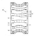
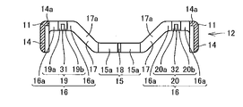
- FIG. 1 It is a figure showing a schematic structure of a maintenance machine concerning a first embodiment of the present invention. It is a figure which shows schematic structure of the needle roller bearing which concerns on 1st embodiment of this invention. It is an expanded sectional view of the pillar part of a cage concerning a first embodiment of the present invention, and is a figure showing signs that needle rollers were stored in a cage. It is an expanded sectional view of the pillar part of the cage concerning a first embodiment of the present invention, and is a figure showing signs that a penetration slot was formed in the approximate center of the diameter direction of a roller stop part.
- the needle roller bearing according to the first embodiment of the present invention will be described below with reference to FIGS. (First embodiment)
- the needle roller bearing according to the present embodiment is, for example, for rotatably supporting a gear shaft of a planetary gear of an automobile transmission, an idler of a transmission, a connecting rod of an engine, and the like.
- the needle roller bearing 50 includes a plurality of needle rollers 10, 10,..., A pair of ring-shaped ring portions 11, 11, and the pair of rings.
- a plurality of column portions 12, 12... For connecting the portions 11, 11 to each other and a plurality of pocket portions 13, 13...
- Each of the plurality of needle rollers 10 in the present embodiment is provided in the pocket portion 13 at substantially equal intervals in the circumferential direction of the pair of ring-shaped ring portions 11 and 11.
- Each of the plurality of needle rollers 10 in the present embodiment is provided in the pocket portion 13 at substantially equal intervals in the circumferential direction of the pair of ring-shaped ring portions 11, 11. It is not limited.
- the cage 30 in the present embodiment is formed of a metal material selected from the group consisting of SCM415, S15CK, SPCC, and STKM12C.
- the pair of ring-shaped ring portions 11, 11 are connected to the longitudinal direction (axial direction) one side and the other side end portions of the plurality of column portions 12, 12.
- the cage 30 has a flange 14 that extends radially inward from the connection position with the pillar 12.
- Each of the plurality of column portions 12, 12... Is positioned relatively radially inward in the axial center region and relatively radially outward in the axial end region. It is located between the pair of column end portions 16 and 16 and between the column center portion 15 and each of the pair of column end portions 16 and 16 and is connected to the column center portion 15 and each of the pair of column end portions 16 and 16.
- the shape of the column part 12 is not limited to this, It can have a desired shape.
- the thickness of the column central portion 15, the column end portion 16 and the column inclined portion 17, the ring portion 11, and the flange portion 14 (hereinafter collectively referred to as “straight portion”) is substantially equal to the column portion 12.
- the recessed part 14a is formed in the connection position of the column end part 16 and the collar part 14 so that the collar part 14 may be folded inside.
- the boundary portion between the column central portion 15 and the column inclined portion 17 in the column portion 12, the boundary portion between the column end portion 16 and the column inclined portion 17, and the boundary portion between the ring portion 11 and the flange portion 14 are collectively referred to as the “boundary portion”) and are thicker than the straight portion.
- the strength of the boundary portion is relatively improved. As a result, it is possible to effectively prevent the cage 30 from being damaged even if stress during rotation of the bearing is concentrated on the boundary portion.
- each of the plurality of column parts 12, 12,... Is formed with a groove part 18 penetrating substantially in the center in the radial direction. More specifically, the groove portion 18 is formed so as to penetrate substantially the center in the radial direction of the column central portion 15 of each of the plurality of column portions 12, 12. In the present embodiment, one groove portion 18 penetrating substantially the center in the radial direction of the column portion 12 is formed, but the present invention is not limited to this.
- the needle roller 10 rolls in a state in which the wall surface 12 a of the column portion 12 facing the pocket portion 13, that is, the needle roller 10 is accommodated in the pocket portion 13.
- On the wall surface 12a of the column 12 facing the surface at least one roller stopper for preventing the needle roller 10 from dropping off and guide surfaces 15a, 16a, 17a for guiding the rotation of the needle roller 10 are formed.
- roller stoppers 19 and 20 are formed one by one on each of the pair of column end portions 16 and 16. And the roller stoppers 19 and 20 prevent the needle rollers 10 from falling off radially outward.
- At least one groove portion extending in the radial direction is formed in the substantially central portion of the roller stopper portions 19 and 20.
- groove portions 21 and 22 extending along the radial direction are respectively formed in substantially central portions of the roller stopper portions 19 and 20.
- the grooves 21 and 22 are formed to extend through the roller stoppers 19 and 20 in the radial direction.
- roller stopper parts 19 and 20 are adjacent to the 1st roller stopper part 19a, 20a adjacent to the axial direction one of the groove parts 21 and 22, and the axial direction other side of the groove parts 21 and 22.
- Second roller stoppers 19b and 20b are adjacent to the 1st roller stopper part 19a, 20a adjacent to the axial direction one of the groove parts 21 and 22, and the axial direction other side of the groove parts 21 and 22.
- the guide surfaces 15a, 16a, and 17a are provided at the column center portion 15, the pair of column end portions 16, and the pair of column inclined portions 17, respectively.
- the guide surface 15a is provided in a region adjacent to the groove 18 in the axial direction.
- the guide surface 16a is provided in the area
- the guide surface 17 a is provided over the entire wall surface 12 a of the pair of column inclined portions 17 and 17.
- the guide surfaces 15a, 16a, and 17a comprise the same plane.
- the portions where the groove portions 21 and 22 of the first roller stopper 19 and the second roller stopper 20 are provided are located on the needle roller 10.
- the lubricant on the rolling surface of the needle roller 10 is not scraped by friction with the roller stoppers 19 and 20 of the retainer 30 without contacting the rolling surface.
- the lubricating oil can be stored in the groove portions 21 and 22, the lubricating oil stored in the in-use groove portions 21 and 22 lubricates the rolling surface of the needle roller 10, so that the needle roller 10 rolls. It is possible to ensure the oil film thickness at the contact surface with the moving surface and the stop portions 19 and 20. For this reason, it becomes difficult for the metal parts of the rolling surface of the needle roller 10 and the raceway surface to directly contact each other, and damage such as peeling is less likely to occur.
- the roller stopper can be formed on at least one of the column central portion 15, the pair of column end portions 16 and 16, and the pair of column inclined portions 17 and 17. Therefore, since the area where the lubricating oil is stored in the groove of the roller stopper increases, the lubricating oil stored in the groove during use lubricates the rolling surface, so that the rolling surface of the needle roller 10 and the stopper The oil film thickness at the contact portion can be ensured.
- first roller stopper 19 and the second roller stopper 20 ensure the contact area between the rolling surface of the needle roller 10 and the stoppers 19 and 20, and the rolling surface of the needle roller 10.
- the oil film thickness at the contact portion with the stopper can be ensured.
- the lubricating oil flows over the rolling surface and the raceway surface of the needle roller 10 through the groove portions 21 and 22 that are penetrated while ensuring the amount of lubricating oil on the rolling surface of the needle roller 10. Therefore, the oil film thickness at the contact surface with the rolling surface of the needle roller 10 and the stoppers 19 and 20 can be further ensured.
- the configuration of the first embodiment is the same as that of the first embodiment except that at least one groove of the roller stopper in the first embodiment is not penetrated in the radial direction. . Therefore, about the structure similar to 1st embodiment, the same code
- the groove portions 31 and 32 in the roller stoppers 19 and 20 are formed so as not to penetrate the roller stoppers 19 and 20 in the radial direction.
- the needle roller bearing 50 according to the present embodiment is the same as the needle roller bearing according to the first embodiment by the non-penetrating groove portions 31 and 32 provided in the roller stoppers 19 and 20 of the cage 30. A certain degree of effect can be achieved.
- the needle roller bearing of the present invention is not limited to the first and second embodiments described above, and can of course be changed as appropriate without departing from the gist of the present invention.
- the cage is formed of a metal material selected from the group consisting of SCM415, S15CK, SPCC, STKM12C), but is not limited thereto.
- the cage may be formed of a polyamide resin selected from the group consisting of polyamide 46 and polyamide 66.
- the roller stopper is formed on the pair of column inclined portions, but is not limited thereto.
- the roller stopper is a column central portion, You may make it form in at least one of a pair of pillar edge part and a pair of pillar inclination part.
- At least one groove is formed in the central portion in the radial direction of the roller stopper, but the present invention is not limited to this.
- the diameter of the roller stopper A plurality of grooves may be formed in the approximate center of the direction.
- the number of the roller stopper portions formed by the groove portions is, for example, in the case of two groove portions, according to the number of groove portions, the first roller stopper portion formed between the two groove portions and one groove portion.
- Three roller stoppers are formed, a second roller stopper formed on the outer side in the radial direction and a third roller stopper formed on the outer side in the radial direction of the other groove.
- the plurality of groove portions make the roller stopper portion a plurality of roller stopper portions formed between adjacent groove portions, a roller stopper portion formed on the radially outer side of the groove portion on one end side in the radial direction, and a radial direction And a roller stopper formed on the radially outer side of the groove on the other end side.
- any configuration may be used as long as it can secure the contact area with the needle roller while securing the amount of lubricating oil in the roller stopper and preventing oil shortage (securing the amount of oil).
- the through groove or the non-through groove is formed at the substantially center in the radial direction of the roller stopper.
- a through groove 33 along the axial direction may be formed in the approximate center of the end surface 13 a of the pocket portion 13 of the cage 30.
- the number of through grooves 33 is not limited.
- through grooves 43 along the axial direction may be formed at both ends of the pocket portion 13 end surface 13 a of the cage 30.
- the number of through grooves 43 is not limited.
- the lubricating oil can also flow through the through groove 33 or the through groove 43 provided in the axial direction of the pocket 13 end surface 13a of the cage 30, and the lubricating oil is not only in the radial direction,
- the entire needle roller bearing 50 can be extended in the axial direction through the through groove 33 or the through groove 43. For this reason, the decrease in the oil film thickness in the needle roller bearing 50 can be suppressed, and the oil film thickness can be further ensured.
- the metal part of the rolling surface of a needle roller 10 and a raceway surface contacts directly by maintaining the oil film thickness in the rolling surface of a needle roller 10, a raceway surface, and the needle roller bearing 50. It becomes difficult and generation
- the needle roller bearing of the present invention is effectively used when rotatably supporting a planetary gear shaft of a transmission for an automobile, an idler of a transmission, a connecting rod of an engine, and the like.
Abstract
In the present invention, a needle roller bearing is provided with a plurality of needle rollers (10) and a cage that includes: a pair of annular ring parts (11, 11); a plurality of column parts (12, 12) that connect the pair of ring parts (11, 11) to each other; and a plurality of pocket parts (13, 13) that accommodate the needle roller (10) between the adjacent column parts (12). At least one roller stop part (19, 20) is formed at a wall surface (12a) of the column part (12), and at least one groove part (21, 22) is formed at the center part of the at least one roller stop part (19, 20) so as to extend along the radial direction.
Description
本発明は、針状ころ軸受に関し、特に、自動車用トランスミッション、エンジンのコンロッド等に使用される針状ころ軸受に関する。
The present invention relates to a needle roller bearing, and more particularly to a needle roller bearing used for an automobile transmission, an engine connecting rod, and the like.
従来より、自動車用オートマチックトランスミッションの遊星歯車やアイドラー、およびオートバイ用エンジンのコンロッド大端用軸受等には、ころと、該ころを保持する保持器とで構成されるケージ&ローラタイプの針状ころ軸受が採用されることが多い。このような軸受は、例えば、特開2000-274439号公報(特許文献1)に記載されている。
2. Description of the Related Art Conventionally, planetary gears and idlers for automatic transmissions for automobiles, and connecting rod large end bearings for motorcycle engines, etc., are cage and roller type needle rollers composed of a roller and a cage that holds the roller. Bearings are often used. Such a bearing is described in, for example, Japanese Unexamined Patent Publication No. 2000-274439 (Patent Document 1).
特許文献1には、針状ころと、該針状ころを収容するための複数のポケット部を有する保持器と、を備える針状ころ軸受が記載されている。針状ころ軸受の保持器のポケット部には、ころ止め部が設けられており、針状ころが、ころ止め部によってポケット部内から外れることなく保持されている。
Patent Document 1 describes a needle roller bearing including a needle roller and a cage having a plurality of pocket portions for accommodating the needle roller. A roller stopper is provided in the pocket portion of the cage of the needle roller bearing, and the needle roller is held by the roller stopper without being detached from the pocket portion.
ところで、特許文献1に記載の針状ころ軸受は、潤滑油が潤沢に存在しない環境下で使用される傾向にある。そのため、針状ころ軸受における潤滑油量が少なく、また、潤滑油の粘度が小さいため、潤滑の条件によっては、潤滑不足に起因する、ピーリング等の損傷が発生する場合がある。
By the way, the needle roller bearing described in Patent Document 1 tends to be used in an environment where there is not enough lubricant. For this reason, the amount of lubricating oil in the needle roller bearing is small, and the viscosity of the lubricating oil is small. Therefore, depending on the lubrication conditions, damage such as peeling may occur due to insufficient lubrication.
また、かかる針状ころ軸受の保持器の形状の場合、軸受の使用時に、針状ころの転動面と保持器のころ止め部とが接触し続けるため、針状ころの転動面における潤滑油が、保持器のころ止め部との摩擦により掻き出されてしまう。その結果、針状ころの転動面上に存在する油量が減少し、針状ころの転動面上の油膜厚さが小さくなる。このため、針状ころの転動面と軌道面との金属部分同士が直接接触し易くなり、ピーリング等の損傷が発生しやすくなる、といった問題がある。
In the case of the shape of the cage of the needle roller bearing, since the rolling surface of the needle roller and the roller stopper of the cage are kept in contact when the bearing is used, lubrication on the rolling surface of the needle roller is performed. Oil is scraped off by friction with the roller stopper of the cage. As a result, the amount of oil existing on the rolling surface of the needle roller is reduced, and the oil film thickness on the rolling surface of the needle roller is reduced. For this reason, there is a problem that the metal portions of the rolling surface and the raceway surface of the needle rollers are easily in direct contact with each other, and damage such as peeling is likely to occur.
そこで、本発明は、斯かる実情に鑑み、針状ころところ止め部との接触部で発生する油膜切れを防ぎ、油膜厚さを確保することのできる、針状ころ軸受を提供することを目的とする。
Therefore, in view of such a situation, the present invention has an object to provide a needle roller bearing that can prevent oil film breakage that occurs at a contact portion between the needle roller and the stopper and can ensure the oil film thickness. And
本発明に係る針状ころ軸受は、複数の針状ころと、円環形状の一対のリング部、該一対のリング部を相互に連結する複数の柱部及び隣り合う前記柱部の間に前記針状ころを収容する複数のポケット部を有する保持器と、を備える針状ころ軸受であって、前記柱部の壁面には、少なくとも一つのころ止め部が形成され、該少なくとも一つのころ止め部の中央部に、径方向に沿って延びる少なくとも一つの溝部が形成されている、ことを特徴とする。
The needle roller bearing according to the present invention includes a plurality of needle rollers, a pair of ring-shaped ring portions, a plurality of column portions interconnecting the pair of ring portions, and the adjacent column portions. A roller bearing having a plurality of pocket portions for accommodating the needle rollers, wherein at least one roller stopper is formed on the wall surface of the column portion, the at least one roller stopper At least one groove portion extending in the radial direction is formed in the central portion of the portion.
上記構成の針状ころ軸受によれば、少なくとも一つのころ止め部の中央部に、径方向に沿って延びる少なくとも一つの溝部が形成されているため、ころ止め部の溝部が設けられた箇所は、針状ころの転動面と接触せず、針状ころの転動面における潤滑油が保持器のころ止め部との摩擦により掻き出されにくくなる。
According to the needle roller bearing configured as described above, since at least one groove portion extending in the radial direction is formed in the central portion of at least one roller stopper portion, the location where the groove portion of the roller stopper portion is provided is In addition, it does not come into contact with the rolling surface of the needle roller, and the lubricating oil on the rolling surface of the needle roller is less likely to be scraped off by friction with the roller stopper of the cage.
また、溝部内に潤滑油を溜めることができることから、使用中溝部に溜められた潤滑油が転動面を潤滑することで、針状ころの転動面ところ止め部との接触部における油膜厚さを確保することができる。このため、針状ころの転動面と軌道面との金属部分同士が直接接触しにくくなり、ピーリング等の損傷が発生しにくくなる。
In addition, since the lubricating oil can be stored in the groove, the lubricating oil stored in the groove during use lubricates the rolling surface, so that the oil film thickness at the contact surface between the rolling surface of the needle roller and the stopper is obtained. Can be secured. For this reason, it becomes difficult for the metal parts of the rolling surface and the raceway surface of the needle roller to be in direct contact with each other, and damage such as peeling is less likely to occur.
本発明の一態様として、前記柱部は、軸方向中央部領域で相対的に径方向内側に位置する柱中央部、軸方向端部領域で相対的に径方向外側に位置する一対の柱端部、および前記柱中央部と前記一対の柱端部それぞれとの間に位置する一対の柱傾斜部を含み、前記複数の針状ころの転動面に対面するのが好ましい。
As one aspect of the present invention, the column portion is a column center portion positioned relatively radially inward in the axial center region, and a pair of column ends positioned relatively radially outward in the axial end region. And a pair of column inclined portions located between the column center portion and each of the pair of column end portions, and preferably face the rolling surfaces of the plurality of needle rollers.
上記構成の針状ころ軸受によれば、ころ止め部は、柱中央部、一対の柱端部及び一対の柱傾斜部の壁面の少なくとも何れかに形成されることができる。そのため、ころ止め部の溝部内に潤滑油を溜める領域が増えることから、使用中溝部に溜められた潤滑油が転動面を潤滑することで、針状ころの転動面ところ止め部との接触部における油膜厚さをより確保することができる。これにより、針状ころの転動面と軌道面との金属部分同士が直接接触しにくくなり、ピーリング等の損傷がより発生しにくくなる。
According to the needle roller bearing having the above-described configuration, the roller stopper can be formed on at least one of the column central portion, the pair of column end portions, and the pair of column inclined portions. For this reason, since the area where the lubricating oil is accumulated in the groove portion of the roller stopper increases, the lubricating oil stored in the groove during use lubricates the rolling surface, so that the rolling surface of the needle roller contacts the stopper portion. The oil film thickness at the contact portion can be further ensured. Thereby, the metal portions of the rolling surface and the raceway surface of the needle roller are less likely to be in direct contact with each other, and damage such as peeling is less likely to occur.
本発明の他態様として、前記ころ止め部は、前記溝部の軸方向一方側に隣接する第一のころ止め部と、前記溝部の軸方向他方側に隣接する第二のころ止め部とを含むのが好ましい。
As another aspect of the present invention, the roller stopper includes a first roller stopper adjacent to one axial side of the groove and a second roller stopper adjacent to the other axial side of the groove. Is preferred.
上記構成の針状ころ軸受によれば、第一のころ止め部及び第二のころ止め部によって、針状ころの転動面ところ止め部との接触面積を確保しつつ、針状ころの転動面ところ止め部との接触部における油膜厚さを確保することができる。
According to the needle roller bearing configured as described above, the first roller stopper and the second roller stopper can secure the contact area between the rolling surface of the needle roller and the stopper. The oil film thickness at the contact portion with the moving surface and the stop portion can be ensured.
本発明の他態様として、前記少なくとも一つの溝部は、径方向に前記ころ止め部を貫通して延びるように形成されているのが好ましい。
As another aspect of the present invention, it is preferable that the at least one groove is formed so as to extend through the roller stopper in the radial direction.
上記構成の針状ころ軸受によれば、溝部は、ころ止め部を径方向に貫通して延びるように形成されているため、針状ころの転動面における潤滑油量を確保しつつ、潤滑油が、貫通された溝部を通って、針状ころの転動面及び軌道面に亘って流れることができ、針状ころの転動面ところ止め部との接触部における油膜厚さをより確保することができる。
According to the needle roller bearing configured as described above, the groove portion is formed so as to extend through the roller stopper portion in the radial direction, and therefore lubrication is ensured while ensuring the amount of lubricating oil on the rolling surface of the needle roller. Oil can flow over the rolling surface and the raceway surface of the needle roller through the penetrated groove, and the oil film thickness at the contact surface with the rolling surface of the needle roller and the stopper is further secured. can do.
本発明のさらに他の態様として、前記少なくとも一つの溝部は、径方向に前記ころ止め部を未貫通であるのが好ましい。
As still another aspect of the present invention, it is preferable that the at least one groove portion does not penetrate the roller stopper in the radial direction.
上記構成の針状ころ軸受によれば、上記針状ころ軸受と同程度の効果を奏することができる。
According to the needle roller bearing configured as described above, it is possible to achieve the same effect as the needle roller bearing.
本発明の別の態様として、前記保持器の前記ポケット部端面の略中央に軸方向に沿った貫通溝が形成されているのが好ましい。
As another aspect of the present invention, it is preferable that a through groove along the axial direction is formed in the approximate center of the end surface of the pocket portion of the cage.
上記構成の針状ころ軸受によれば、潤滑油が、保持器のポケット部端面の略中央に設けられた貫通溝にも流れることができ、潤滑油が、径方向のみならず、貫通溝を通って軸方向に針状ころ軸受全体に行き渡ることができる。このため、針状ころ軸受における油膜厚さの減少を抑制でき、油膜厚さをさらに確保することができる。
According to the needle roller bearing configured as described above, the lubricating oil can also flow into the through groove provided in the approximate center of the end surface of the pocket portion of the cage, and the lubricating oil not only in the radial direction but also through the through groove. It can pass through the entire needle roller bearing in the axial direction. For this reason, a decrease in the oil film thickness in the needle roller bearing can be suppressed, and the oil film thickness can be further ensured.
そして、針状ころの転動面、軌道面及び針状ころ軸受における油膜厚さが保たれることにより、針状ころの転動面と軌道面との金属部分同士が直接接触しにくくなり、ピーリング等の発生をさらに抑制できる。
And, by maintaining the oil film thickness in the rolling surface of the needle roller, the raceway surface and the needle roller bearing, it becomes difficult for the metal parts of the rolling surface of the needle roller and the raceway surface to directly contact each other, The occurrence of peeling and the like can be further suppressed.
本発明のさらに別の態様として、前記保持器の前記ポケット部端面の両端に軸方向に沿った貫通溝が形成されているのが好ましい。
As still another aspect of the present invention, it is preferable that through grooves along the axial direction are formed at both ends of the pocket portion end face of the cage.
上記構成の針状ころ軸受によれば、潤滑油が、保持器のポケット部端面の両端に設けられた貫通溝にも流れることができ、潤滑油が、径方向のみならず、貫通溝を通って軸方向に針状ころ軸受全体に行き渡ることができる。このため、針状ころ軸受における油膜厚さの減少を抑制でき、油膜厚さをさらに確保することができる。
According to the needle roller bearing configured as described above, the lubricating oil can also flow through the through grooves provided at both ends of the pocket end face of the cage, and the lubricating oil passes through the through grooves as well as in the radial direction. Thus, the entire needle roller bearing can be extended in the axial direction. For this reason, a decrease in the oil film thickness in the needle roller bearing can be suppressed, and the oil film thickness can be further ensured.
そして、針状ころの転動面、軌道面及び針状ころ軸受における油膜厚さが保たれることにより、針状ころの転動面と軌道面との金属部分同士が直接接触しにくくなり、ピーリング等の発生をさらに抑制できる。
And, by maintaining the oil film thickness in the rolling surface of the needle roller, the raceway surface and the needle roller bearing, it becomes difficult for the metal parts of the rolling surface of the needle roller and the raceway surface to directly contact each other, The occurrence of peeling and the like can be further suppressed.
本発明のさらに別の態様として、前記保持器が、SCM415、S15CK、SPCC、STKM12Cからなる群より選択される金属材料で形成されているのが好ましい。
As still another aspect of the present invention, it is preferable that the cage is made of a metal material selected from the group consisting of SCM415, S15CK, SPCC, and STKM12C.
本発明のさらに別の態様として、前記保持器が、ポリアミド46、ポリアミド66からなる群より選択されるポリアミド樹脂で形成されているのが好ましい。
As still another aspect of the present invention, the cage is preferably made of a polyamide resin selected from the group consisting of polyamide 46 and polyamide 66.
以上のように、本発明の針状ころ軸受によれば、針状ころところ止め部との接触部で発生する油膜切れを防ぎ、油膜厚さを確保することができる。その結果、針状ころの転動面、軌道面及び針状ころ軸受における油膜厚さが保たれることにより、針状ころの転動面と軌道面との金属部分同士が直接接触しにくくなり、ピーリング等の表面起点型損傷の発生を抑制できる。
As described above, according to the needle roller bearing of the present invention, it is possible to prevent oil film breakage that occurs at the contact portion between the needle roller and the stopper, and to secure the oil film thickness. As a result, the oil film thickness on the rolling surface, raceway surface, and needle roller bearing of the needle roller is maintained, so that the metal portions of the rolling surface of the needle roller and the raceway surface are less likely to be in direct contact with each other. The occurrence of surface-origin damage such as peeling can be suppressed.
以下、本発明の第一の実施形態に係る針状ころ軸受について、図1~4を参照して説明する。
(第一の実施形態)
本実施形態に係る針状ころ軸受は、例えば、自動車用トランスミッションの遊星歯車の歯車軸や、トランスミッションのアイドラー、及びエンジンのコンロッド等を回転自在に支持するためのものである。 The needle roller bearing according to the first embodiment of the present invention will be described below with reference to FIGS.
(First embodiment)
The needle roller bearing according to the present embodiment is, for example, for rotatably supporting a gear shaft of a planetary gear of an automobile transmission, an idler of a transmission, a connecting rod of an engine, and the like.
図1及び2に示すように、本実施形態に係る針状ころ軸受50は、複数の針状ころ10,10・・・と、円環形状の一対のリング部11,11、該一対のリング部11,11を相互に連結する複数の柱部12,12・・・及び隣り合う柱部12の間に各針状ころ10を収容する複数のポケット部13,13・・・を有する保持器30と、を備える。
As shown in FIGS. 1 and 2, the needle roller bearing 50 according to the present embodiment includes a plurality of needle rollers 10, 10,..., A pair of ring-shaped ring portions 11, 11, and the pair of rings. A plurality of column portions 12, 12... For connecting the portions 11, 11 to each other and a plurality of pocket portions 13, 13... For accommodating the needle rollers 10 between the adjacent column portions 12. 30.
本実施形態における複数の針状ころ10のそれぞれは、ポケット部13内に、円環形状の一対のリング部11,11の円周方向に略等間隔をあけて設けられている。本実施形態における複数の針状ころ10のそれぞれは、ポケット部13内に、円環形状の一対のリング部11,11の円周方向に略等間隔をあけて設けられているが、これに限定されるものではない。
Each of the plurality of needle rollers 10 in the present embodiment is provided in the pocket portion 13 at substantially equal intervals in the circumferential direction of the pair of ring-shaped ring portions 11 and 11. Each of the plurality of needle rollers 10 in the present embodiment is provided in the pocket portion 13 at substantially equal intervals in the circumferential direction of the pair of ring-shaped ring portions 11, 11. It is not limited.
本実施形態における保持器30は、SCM415、S15CK、SPCC、STKM12Cからなる群より選択される金属材料で形成されている。
The cage 30 in the present embodiment is formed of a metal material selected from the group consisting of SCM415, S15CK, SPCC, and STKM12C.
保持器30において、円環形状の一対のリング部11,11は、複数の柱部12,12・・・のそれぞれの長手方向(軸方向)一方側及び他方側端部と接続されている。また、保持器30は、柱部12との接続位置から径方向内側に延びる鍔部14を有する。
In the cage 30, the pair of ring-shaped ring portions 11, 11 are connected to the longitudinal direction (axial direction) one side and the other side end portions of the plurality of column portions 12, 12. The cage 30 has a flange 14 that extends radially inward from the connection position with the pillar 12.
複数の柱部12,12・・・のそれぞれは、軸方向中央部領域で相対的に径方向内側に位置する柱中央部15と、軸方向端部領域で相対的に径方向外側に位置する一対の柱端部16,16と、柱中央部15と一対の柱端部16,16のそれぞれとの間に位置し、柱中央部15及び一対の柱端部16,16のそれぞれと接続される一対の柱傾斜部17,17と、を含む。なお、柱部12の形状は、これに限定されるものではなく、所望の形状を有することができる。
Each of the plurality of column portions 12, 12... Is positioned relatively radially inward in the axial center region and relatively radially outward in the axial end region. It is located between the pair of column end portions 16 and 16 and between the column center portion 15 and each of the pair of column end portions 16 and 16 and is connected to the column center portion 15 and each of the pair of column end portions 16 and 16. A pair of column inclined portions 17 and 17. In addition, the shape of the column part 12 is not limited to this, It can have a desired shape.
柱部12における柱中央部15、柱端部16及び柱傾斜部17、及びリング部11、鍔部14、(以下、これらを総称して「直線部分」という)の肉厚は、実質的に等しく設定されている。なお、柱端部16と鍔部14との接続位置には、鍔部14が内側に折り込まれるように凹部14aが形成されている。
The thickness of the column central portion 15, the column end portion 16 and the column inclined portion 17, the ring portion 11, and the flange portion 14 (hereinafter collectively referred to as “straight portion”) is substantially equal to the column portion 12. Are set equal. In addition, the recessed part 14a is formed in the connection position of the column end part 16 and the collar part 14 so that the collar part 14 may be folded inside.
一方、柱部12における柱中央部15と柱傾斜部17との境界部分、柱端部16と柱傾斜部17との境界部分、及びリング部11と鍔部14との境界部分分(以下、これらを総称して「境界部分」という)の肉厚は、直線部分の肉厚より厚くなっている。
On the other hand, the boundary portion between the column central portion 15 and the column inclined portion 17 in the column portion 12, the boundary portion between the column end portion 16 and the column inclined portion 17, and the boundary portion between the ring portion 11 and the flange portion 14 (hereinafter, These are collectively referred to as the “boundary portion”) and are thicker than the straight portion.
これにより、境界部分の強度が相対的に向上する。その結果、軸受回転時の応力が境界部分に集中しても保持器30の破損を有効に防止することができる。
Thereby, the strength of the boundary portion is relatively improved. As a result, it is possible to effectively prevent the cage 30 from being damaged even if stress during rotation of the bearing is concentrated on the boundary portion.
また、複数の柱部12,12・・・のそれぞれには、径方向の略中央に貫通する溝部18が形成されている。より具体的には、溝部18は、複数の柱部12,12・・・のそれぞれの柱中央部15の径方向の略中央に貫通するように形成されている。本実施形態においては、柱部12の径方向の略中央に貫通する溝部18が一つ形成されているが、これに限定されるものではない。
Further, each of the plurality of column parts 12, 12,... Is formed with a groove part 18 penetrating substantially in the center in the radial direction. More specifically, the groove portion 18 is formed so as to penetrate substantially the center in the radial direction of the column central portion 15 of each of the plurality of column portions 12, 12. In the present embodiment, one groove portion 18 penetrating substantially the center in the radial direction of the column portion 12 is formed, but the present invention is not limited to this.
次に、図3および図4に示すように、ポケット部13に対面する柱部12の壁面12a、すなわち、針状ころ10がポケット部13に収容された状態で、針状ころ10の転動面に対面する柱部12の壁面12aには、針状ころ10の脱落を防止する少なくとも一つのころ止め部と、針状ころ10の回転を案内する案内面15a,16a,17aと、が形成されている。
Next, as shown in FIGS. 3 and 4, the needle roller 10 rolls in a state in which the wall surface 12 a of the column portion 12 facing the pocket portion 13, that is, the needle roller 10 is accommodated in the pocket portion 13. On the wall surface 12a of the column 12 facing the surface, at least one roller stopper for preventing the needle roller 10 from dropping off and guide surfaces 15a, 16a, 17a for guiding the rotation of the needle roller 10 are formed. Has been.
本実施形態において、ころ止め部19,20は、一対の柱端部16,16のそれぞれに一つずつ形成されている。そして、ころ止め部19,20は、針状ころ10の径方向外側への脱落を防止する。
In this embodiment, the roller stoppers 19 and 20 are formed one by one on each of the pair of column end portions 16 and 16. And the roller stoppers 19 and 20 prevent the needle rollers 10 from falling off radially outward.
また、ころ止め部19,20の略中央部に、径方向に沿って延びる少なくとも一つの溝部が形成されている。
Moreover, at least one groove portion extending in the radial direction is formed in the substantially central portion of the roller stopper portions 19 and 20.
より具体的には、ころ止め部19,20の略中央部に、それぞれ、径方向に沿って延びる溝部21,22が形成されている。溝部21,22は、径方向にころ止め部19,20を貫通して延びるように形成されている。
More specifically, groove portions 21 and 22 extending along the radial direction are respectively formed in substantially central portions of the roller stopper portions 19 and 20. The grooves 21 and 22 are formed to extend through the roller stoppers 19 and 20 in the radial direction.
そして、上記溝部21,22によって、ころ止め部19,20は、溝部21、22の軸方向一方に隣接する第一のころ止め部19a,20aと、溝部21、22の軸方向他方に隣接する第二のころ止め部19b,20bと、を含む。
And by the said groove parts 21 and 22, the roller stopper parts 19 and 20 are adjacent to the 1st roller stopper part 19a, 20a adjacent to the axial direction one of the groove parts 21 and 22, and the axial direction other side of the groove parts 21 and 22. Second roller stoppers 19b and 20b.
本実施形態において、案内面15a,16a,17aは、それぞれ、柱中央部15,一対の柱端部16,一対の柱傾斜部17に設けられている。
In the present embodiment, the guide surfaces 15a, 16a, and 17a are provided at the column center portion 15, the pair of column end portions 16, and the pair of column inclined portions 17, respectively.
より具体的には、案内面15aは、上述の溝部18の軸方向に隣接する領域に設けられている。案内面16aは、一対の柱端部16,16のそれぞれに形成された第一のころ止め部19及び第二のころ止め部20の軸方向に隣接する領域に設けられている。案内面17aは、一対の柱傾斜部17,17の壁面12aの全域に亘って設けられている。また、案内面15a,16a,17aは、同一の平面を構成している。
More specifically, the guide surface 15a is provided in a region adjacent to the groove 18 in the axial direction. The guide surface 16a is provided in the area | region adjacent to the axial direction of the 1st roller stopper part 19 and the 2nd roller stopper part 20 which were formed in each of a pair of column edge parts 16 and 16. As shown in FIG. The guide surface 17 a is provided over the entire wall surface 12 a of the pair of column inclined portions 17 and 17. Moreover, the guide surfaces 15a, 16a, and 17a comprise the same plane.
以上のように、本実施形態に係る針状ころ軸受50においては、第一のころ止め部19及び第二のころ止め部20の溝部21,22が設けられた箇所は、針状ころ10の転動面と接触せず、針状ころ10の転動面における潤滑油が保持器30のころ止め部19,20との摩擦により掻き出されにくくなる。
As described above, in the needle roller bearing 50 according to the present embodiment, the portions where the groove portions 21 and 22 of the first roller stopper 19 and the second roller stopper 20 are provided are located on the needle roller 10. The lubricant on the rolling surface of the needle roller 10 is not scraped by friction with the roller stoppers 19 and 20 of the retainer 30 without contacting the rolling surface.
また、溝部21,22内に潤滑油を溜めることができることから、使用中溝部21,22に溜められた潤滑油が針状ころ10の転動面を潤滑することで、針状ころ10の転動面ところ止め部19,20との接触部における油膜厚さを確保することができる。このため、針状ころ10の転動面と軌道面との金属部分同士が直接接触しにくくなり、ピーリング等の損傷が発生しにくくなる。
Further, since the lubricating oil can be stored in the groove portions 21 and 22, the lubricating oil stored in the in- use groove portions 21 and 22 lubricates the rolling surface of the needle roller 10, so that the needle roller 10 rolls. It is possible to ensure the oil film thickness at the contact surface with the moving surface and the stop portions 19 and 20. For this reason, it becomes difficult for the metal parts of the rolling surface of the needle roller 10 and the raceway surface to directly contact each other, and damage such as peeling is less likely to occur.
また、ころ止め部は、柱中央部15、一対の柱端部16,16及び一対の柱傾斜部17,17の壁面12aの少なくとも何れかに形成されることができる。そのため、ころ止め部の溝部内に潤滑油を溜める領域が増えることから、使用中溝部に溜められた潤滑油が転動面を潤滑することで、針状ころ10の転動面ところ止め部との接触部における油膜厚さを確保することができる。
Further, the roller stopper can be formed on at least one of the column central portion 15, the pair of column end portions 16 and 16, and the pair of column inclined portions 17 and 17. Therefore, since the area where the lubricating oil is stored in the groove of the roller stopper increases, the lubricating oil stored in the groove during use lubricates the rolling surface, so that the rolling surface of the needle roller 10 and the stopper The oil film thickness at the contact portion can be ensured.
また、第一のころ止め部19及び第二のころ止め部20によって、針状ころ10の転動面ところ止め部19,20との接触面積を確保しつつ、針状ころ10の転動面ところ止め部との接触部における油膜厚さを確保することができる。
Further, the first roller stopper 19 and the second roller stopper 20 ensure the contact area between the rolling surface of the needle roller 10 and the stoppers 19 and 20, and the rolling surface of the needle roller 10. However, the oil film thickness at the contact portion with the stopper can be ensured.
また、針状ころ10の転動面における潤滑油量を確保しつつ、潤滑油が、貫通された溝部21,22を通って、針状ころ10の転動面及び軌道面に亘って流れることができ、針状ころ10の転動面ところ止め部19,20との接触部における油膜厚さをより確保することができる。
Further, the lubricating oil flows over the rolling surface and the raceway surface of the needle roller 10 through the groove portions 21 and 22 that are penetrated while ensuring the amount of lubricating oil on the rolling surface of the needle roller 10. Therefore, the oil film thickness at the contact surface with the rolling surface of the needle roller 10 and the stoppers 19 and 20 can be further ensured.
以下、本発明の第二の実施形態に係る針状ころ軸受について、図5を参照して説明する。
(第二の実施形態)
本実施形態に係る針状ころ軸受では、上記第一の実施形態におけるころ止め部の少なくとも一つの溝部が、径方向に未貫通であること以外は、第一の実施形態の構成と同様である。そのため、第一の実施形態と同様の構成については、同一の符号を付してその説明を繰り返さない。 Hereinafter, a needle roller bearing according to a second embodiment of the present invention will be described with reference to FIG.
(Second embodiment)
In the needle roller bearing according to this embodiment, the configuration of the first embodiment is the same as that of the first embodiment except that at least one groove of the roller stopper in the first embodiment is not penetrated in the radial direction. . Therefore, about the structure similar to 1st embodiment, the same code | symbol is attached | subjected and the description is not repeated.
本実施形態では、図5に示すように、ころ止め部19,20における溝部31,32が、ころ止め部19,20を径方向に未貫通に形成されている。
In this embodiment, as shown in FIG. 5, the groove portions 31 and 32 in the roller stoppers 19 and 20 are formed so as not to penetrate the roller stoppers 19 and 20 in the radial direction.
本実施形態に係る針状ころ軸受50においては、保持器30のころ止め部19,20に設けられた未貫通の溝部31,32により、上記第一の実施形態に係る針状ころ軸受と同程度の効果を奏することができる。
The needle roller bearing 50 according to the present embodiment is the same as the needle roller bearing according to the first embodiment by the non-penetrating groove portions 31 and 32 provided in the roller stoppers 19 and 20 of the cage 30. A certain degree of effect can be achieved.
尚、本発明の針状ころ軸受は、上記第一及び第二の実施形態に限定されるものではなく、本発明の要旨を逸脱しない範囲で適宜変更し得ることは勿論のことである。
The needle roller bearing of the present invention is not limited to the first and second embodiments described above, and can of course be changed as appropriate without departing from the gist of the present invention.
上記第一及び第二の実施形態において、保持器は、SCM415、S15CK、SPCC、STKM12C)からなる群より選択される金属材料で形成されているが、これに限定されるものではなく、例えば、保持器は、ポリアミド46、ポリアミド66からなる群より選択されるポリアミド樹脂で形成されていてもよい。
In the first and second embodiments, the cage is formed of a metal material selected from the group consisting of SCM415, S15CK, SPCC, STKM12C), but is not limited thereto. The cage may be formed of a polyamide resin selected from the group consisting of polyamide 46 and polyamide 66.
上記第一及び第二の実施形態において、ころ止め部は、一対の柱傾斜部に形成されるようにしたが、これに限定されるものではなく、例えば、ころ止め部は、柱中央部、一対の柱端部及び一対の柱傾斜部の少なくとも一つに形成されるようにしてもよい。
In the first and second embodiments, the roller stopper is formed on the pair of column inclined portions, but is not limited thereto. For example, the roller stopper is a column central portion, You may make it form in at least one of a pair of pillar edge part and a pair of pillar inclination part.
上記第一及び第二の実施形態において、ころ止め部の径方向の中央部に少なくとも一つの溝部が形成されるようにしたが、これに限定されるものではなく、例えば、ころ止め部の径方向の略中央部に複数の溝部が形成されるようにしてもよい。
In the first and second embodiments, at least one groove is formed in the central portion in the radial direction of the roller stopper, but the present invention is not limited to this. For example, the diameter of the roller stopper A plurality of grooves may be formed in the approximate center of the direction.
この場合、溝部によって形成されるころ止め部の数は、溝部の数に応じて、例えば、溝部が2つの場合、2つの溝部の間に形成される第一のころ止め部と、一方の溝部の径方向外側に形成される第二のころ止め部と、他方の溝部の径方向外側に形成される第三のころ止め部との、3つのころ止め部が形成されるようになる。
In this case, the number of the roller stopper portions formed by the groove portions is, for example, in the case of two groove portions, according to the number of groove portions, the first roller stopper portion formed between the two groove portions and one groove portion. Three roller stoppers are formed, a second roller stopper formed on the outer side in the radial direction and a third roller stopper formed on the outer side in the radial direction of the other groove.
すなわち、複数の溝部によって、ころ止め部は、隣り合う溝部間に形成される複数のころ止め部と、径方向の一端側の溝部の径方向外側に形成されるころ止め部と、径方向の他端側の溝部の径方向外側に形成されるころ止め部と、によって構成される。
In other words, the plurality of groove portions make the roller stopper portion a plurality of roller stopper portions formed between adjacent groove portions, a roller stopper portion formed on the radially outer side of the groove portion on one end side in the radial direction, and a radial direction And a roller stopper formed on the radially outer side of the groove on the other end side.
要は、針状ころとの接触面積を確保しつつ、ころ止め部における潤滑油量を確保し、油切れを防ぐ(油量を確保する)ことができる構成であればよい。ころ止め部の径方向の略中央に貫通溝又は未貫通溝が形成される場合の何れにおいても同様である。
In short, any configuration may be used as long as it can secure the contact area with the needle roller while securing the amount of lubricating oil in the roller stopper and preventing oil shortage (securing the amount of oil). The same applies to the case where the through groove or the non-through groove is formed at the substantially center in the radial direction of the roller stopper.
上記第一及び第二の実施形態において、図6に示すように、保持器30のポケット部13端面13aの略中央に軸方向に沿った貫通溝33が形成されるようにしてもよい。なお、貫通溝33の数は限定されるものではない。
In the first and second embodiments, as shown in FIG. 6, a through groove 33 along the axial direction may be formed in the approximate center of the end surface 13 a of the pocket portion 13 of the cage 30. The number of through grooves 33 is not limited.
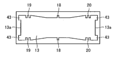
あるいは、上記第一及び第二の実施形態において、図7に示すように、保持器30のポケット部13端面13aの両端に軸方向に沿った貫通溝43が形成されようにしてもよい。なお、貫通溝43の数は限定されるものではない。
Alternatively, in the first and second embodiments, as shown in FIG. 7, through grooves 43 along the axial direction may be formed at both ends of the pocket portion 13 end surface 13 a of the cage 30. The number of through grooves 43 is not limited.
何れの場合においても、潤滑油が、保持器30のポケット部13端面13aの軸方向に設けられた貫通溝33又は貫通溝43にも流れることができ、潤滑油が、径方向のみならず、貫通溝33又は貫通溝43を通って軸方向に針状ころ軸受50全体に行き渡ることができる。このため、針状ころ軸受50における油膜厚さの減少を抑制でき、油膜厚さをさらに確保することができる。
In any case, the lubricating oil can also flow through the through groove 33 or the through groove 43 provided in the axial direction of the pocket 13 end surface 13a of the cage 30, and the lubricating oil is not only in the radial direction, The entire needle roller bearing 50 can be extended in the axial direction through the through groove 33 or the through groove 43. For this reason, the decrease in the oil film thickness in the needle roller bearing 50 can be suppressed, and the oil film thickness can be further ensured.
そして、針状ころ10の転動面、軌道面及び針状ころ軸受50における油膜厚さが保たれることにより、針状ころ10の転動面と軌道面との金属部分同士が直接接触しにくくなり、ピーリング等の発生をさらに抑制できる。
And the metal part of the rolling surface of a needle roller 10 and a raceway surface contacts directly by maintaining the oil film thickness in the rolling surface of a needle roller 10, a raceway surface, and the needle roller bearing 50. It becomes difficult and generation | occurrence | production of peeling etc. can be suppressed further.
本発明の針状ころ軸受は、自動車用トランスミッションの遊星歯車の歯車軸や、トランスミッションのアイドラー、及びエンジンのコンロッド等を回転自在に支持する場合に有効に利用される。
The needle roller bearing of the present invention is effectively used when rotatably supporting a planetary gear shaft of a transmission for an automobile, an idler of a transmission, a connecting rod of an engine, and the like.
10 複数の針状ころ、11 一対のリング部、12 複数の柱部、12a 壁面、13 複数のポケット部、13a 端面、14 鍔部、15 柱中央部、16 一対の柱端部、17 一対の柱傾斜部、15a,16a,17a 案内面、18 溝部、19,20 ころ止め部、21,22 溝部、 30保持器、31,32 溝部、33,43 貫通溝、50 針状ころ軸受。
10 needle rollers, 11 pairs of ring parts, 12 pillars, 12a wall surface, 13 pockets, 13a end face, 14 collar, 15 pillar center, 16 pairs of pillar ends, 17 pairs Column inclined part, 15a, 16a, 17a guide surface, 18 groove part, 19, 20 roller stopper, 21, 22 groove part, 30 cage, 31, 32 groove part, 33, 43 through groove, 50 needle roller bearing.
Claims (9)
- 複数の針状ころと、
円環形状の一対のリング部、該一対のリング部を相互に連結する複数の柱部及び隣り合う前記柱部の間に前記針状ころを収容する複数のポケット部を有する保持器と、を備える針状ころ軸受であって、
前記柱部の壁面には、少なくとも一つのころ止め部が形成され、
該少なくとも一つのころ止め部の中央部に、径方向に沿って延びる少なくとも一つの溝部が形成されている、針状ころ軸受。 A plurality of needle rollers;
A pair of ring-shaped ring portions, a plurality of column portions interconnecting the pair of ring portions, and a cage having a plurality of pocket portions for accommodating the needle rollers between the adjacent column portions; A needle roller bearing comprising:
At least one roller stopper is formed on the wall surface of the pillar,
A needle roller bearing, wherein at least one groove extending along the radial direction is formed in a central portion of the at least one roller stopper. - 前記柱部は、軸方向中央部領域で相対的に径方向内側に位置する柱中央部、軸方向端部領域で相対的に径方向外側に位置する一対の柱端部、および前記柱中央部と前記一対の柱端部それぞれとの間に位置する一対の柱傾斜部を含み、前記複数の針状ころの転動面に対面する、請求項1に記載の針状ころ軸受。 The column portion is a column center portion that is relatively radially inward in the axial center region, a pair of column end portions that are relatively radially outward in the axial end region, and the column center portion The needle roller bearing according to claim 1, further comprising a pair of column inclined portions positioned between each of the pair of column end portions and facing a rolling surface of the plurality of needle rollers.
- 前記ころ止め部は、前記溝部の軸方向一方側に隣接する第一のころ止め部と、前記溝部の軸方向他方側に隣接する第二のころ止め部とを含む、請求項1に記載の針状ころ軸受。 The said roller stop part contains the 1st roller stop part adjacent to the axial direction one side of the said groove part, and the 2nd roller stop part adjacent to the axial direction other side of the said groove part. Needle roller bearing.
- 前記少なくとも一つの溝部は、径方向に前記ころ止め部を貫通して延びるように形成されている、請求項1に記載の針状ころ軸受。 The needle roller bearing according to claim 1, wherein the at least one groove portion is formed so as to extend through the roller stopper portion in a radial direction.
- 前記少なくとも一つの溝部は、径方向に前記ころ止め部を未貫通である、請求項1に記載の針状ころ軸受。 The needle roller bearing according to claim 1, wherein the at least one groove portion does not penetrate the roller stopper in a radial direction.
- 前記保持器の前記ポケット部端面の略中央に径方向に沿った貫通溝が形成されている、請求項1~5の何れかに記載の針状ころ軸受。 The needle roller bearing according to any one of claims 1 to 5, wherein a through groove along a radial direction is formed at a substantially center of the end surface of the pocket portion of the cage.
- 前記保持器の前記ポケット部端面の両端に径方向に沿った貫通溝が形成されている、請求項1~6の何れかに記載の針状ころ軸受。 The needle roller bearing according to any one of claims 1 to 6, wherein through grooves along the radial direction are formed at both ends of the end surface of the pocket portion of the cage.
- 前記保持器がSCM415,S15CK,SPCC,STKM12Cからなる群より選択される金属材料で形成されている、請求項1~7の何れかに記載の針状ころ軸受。 The needle roller bearing according to any one of claims 1 to 7, wherein the cage is made of a metal material selected from the group consisting of SCM415, S15CK, SPCC, and STKM12C.
- 前記保持器がポリアミド46、ポリアミド66からなる群より選択されるポリアミド樹脂で形成されている、請求項1~7の何れかに記載の針状ころ軸受。 The needle roller bearing according to any one of claims 1 to 7, wherein the cage is made of a polyamide resin selected from the group consisting of polyamide 46 and polyamide 66.
Applications Claiming Priority (2)
| Application Number | Priority Date | Filing Date | Title |
|---|---|---|---|
| JP2015-020540 | 2015-02-04 | ||
| JP2015020540A JP2016142391A (en) | 2015-02-04 | 2015-02-04 | Needle roller bearing |
Publications (1)
| Publication Number | Publication Date |
|---|---|
| WO2016125573A1 true WO2016125573A1 (en) | 2016-08-11 |
Family
ID=56563924
Family Applications (1)
| Application Number | Title | Priority Date | Filing Date |
|---|---|---|---|
| PCT/JP2016/051359 WO2016125573A1 (en) | 2015-02-04 | 2016-01-19 | Needle roller bearing |
Country Status (2)
| Country | Link |
|---|---|
| JP (1) | JP2016142391A (en) |
| WO (1) | WO2016125573A1 (en) |
Families Citing this family (1)
| Publication number | Priority date | Publication date | Assignee | Title |
|---|---|---|---|---|
| DE102017115906A1 (en) * | 2017-07-14 | 2019-01-17 | Schaeffler Technologies AG & Co. KG | Bearing cage for roller bearings and roller bearings |
Citations (7)
| Publication number | Priority date | Publication date | Assignee | Title |
|---|---|---|---|---|
| JPH11108065A (en) * | 1997-08-06 | 1999-04-20 | Ntn Corp | Needle roller bearing |
| JPH11201149A (en) * | 1998-01-12 | 1999-07-27 | Koyo Seiko Co Ltd | Tapered roller bearing |
| JP2001041250A (en) * | 1999-08-02 | 2001-02-13 | Koyo Seiko Co Ltd | Holder for rolling bearing |
| JP2002242938A (en) * | 2001-02-16 | 2002-08-28 | Nsk Ltd | Cage for roller bearing |
| JP2007127224A (en) * | 2005-11-04 | 2007-05-24 | Ntn Corp | Needle roller bearing and crankshaft support structure |
| JP2009236146A (en) * | 2008-03-26 | 2009-10-15 | Ntn Corp | Rolling bearing cage, rolling bearing, and rolling bearing cage manufacturing method |
| JP2013177984A (en) * | 2013-06-26 | 2013-09-09 | Ntn Corp | Roller with retainer |
-
2015
- 2015-02-04 JP JP2015020540A patent/JP2016142391A/en active Pending
-
2016
- 2016-01-19 WO PCT/JP2016/051359 patent/WO2016125573A1/en active Application Filing
Patent Citations (7)
| Publication number | Priority date | Publication date | Assignee | Title |
|---|---|---|---|---|
| JPH11108065A (en) * | 1997-08-06 | 1999-04-20 | Ntn Corp | Needle roller bearing |
| JPH11201149A (en) * | 1998-01-12 | 1999-07-27 | Koyo Seiko Co Ltd | Tapered roller bearing |
| JP2001041250A (en) * | 1999-08-02 | 2001-02-13 | Koyo Seiko Co Ltd | Holder for rolling bearing |
| JP2002242938A (en) * | 2001-02-16 | 2002-08-28 | Nsk Ltd | Cage for roller bearing |
| JP2007127224A (en) * | 2005-11-04 | 2007-05-24 | Ntn Corp | Needle roller bearing and crankshaft support structure |
| JP2009236146A (en) * | 2008-03-26 | 2009-10-15 | Ntn Corp | Rolling bearing cage, rolling bearing, and rolling bearing cage manufacturing method |
| JP2013177984A (en) * | 2013-06-26 | 2013-09-09 | Ntn Corp | Roller with retainer |
Also Published As
| Publication number | Publication date |
|---|---|
| JP2016142391A (en) | 2016-08-08 |
Similar Documents
| Publication | Publication Date | Title |
|---|---|---|
| EP3048318B1 (en) | Bearing structure | |
| JP5129762B2 (en) | Angular contact ball bearings | |
| JP2005321049A (en) | Roller bearing | |
| JP2012041940A (en) | Retainer of cylindrical roller bearing and cylindrical roller bearing | |
| JP2007321802A (en) | Conical roller bearing | |
| JP2015064087A (en) | Deep groove ball bearing | |
| WO2016125573A1 (en) | Needle roller bearing | |
| JP2018087630A (en) | Ball bearing retainer and ball bearing | |
| JP2012246972A (en) | Roller thrust bearing | |
| JP5012383B2 (en) | Radial roller bearing with cage | |
| JP2007071292A (en) | Roller bearing | |
| CN111566367B (en) | Roller with retainer and planetary gear supporting structure | |
| US20090028486A1 (en) | Tapered roller bearing | |
| JP6349681B2 (en) | Radial roller bearing cage and radial roller bearing | |
| JP2015078742A (en) | Cage for radial roller bearing, and radial roller bearing | |
| JP2006258262A (en) | Double-row rolling bearing | |
| JP2015222089A (en) | Needle bearing | |
| JP2015031390A (en) | Thrust roller bearing | |
| JP2011196393A (en) | Thrust roller bearing | |
| JP2009092158A (en) | Rolling bearing | |
| JP5315881B2 (en) | Rolling bearing | |
| JP2016142331A (en) | Radial roller bearing | |
| JP2018044576A (en) | Rolling bearing for drive unit | |
| JP2008111505A (en) | Thrust needle roller bearing | |
| JP6759544B2 (en) | Thrust roller bearing |
Legal Events
| Date | Code | Title | Description |
|---|---|---|---|
| 121 | Ep: the epo has been informed by wipo that ep was designated in this application |
Ref document number: 16746404 Country of ref document: EP Kind code of ref document: A1 |
|
| NENP | Non-entry into the national phase |
Ref country code: DE |
|
| 122 | Ep: pct application non-entry in european phase |
Ref document number: 16746404 Country of ref document: EP Kind code of ref document: A1 |