WO2016125546A1 - Connector - Google Patents
Connector Download PDFInfo
- Publication number
- WO2016125546A1 WO2016125546A1 PCT/JP2016/050836 JP2016050836W WO2016125546A1 WO 2016125546 A1 WO2016125546 A1 WO 2016125546A1 JP 2016050836 W JP2016050836 W JP 2016050836W WO 2016125546 A1 WO2016125546 A1 WO 2016125546A1
- Authority
- WO
- WIPO (PCT)
- Prior art keywords
- contact
- switch
- fixed
- movable
- connector
- Prior art date
Links
Images


Classifications
-
- H—ELECTRICITY
- H01—ELECTRIC ELEMENTS
- H01R—ELECTRICALLY-CONDUCTIVE CONNECTIONS; STRUCTURAL ASSOCIATIONS OF A PLURALITY OF MUTUALLY-INSULATED ELECTRICAL CONNECTING ELEMENTS; COUPLING DEVICES; CURRENT COLLECTORS
- H01R13/00—Details of coupling devices of the kinds covered by groups H01R12/70 or H01R24/00 - H01R33/00
- H01R13/66—Structural association with built-in electrical component
- H01R13/70—Structural association with built-in electrical component with built-in switch
- H01R13/707—Structural association with built-in electrical component with built-in switch interlocked with contact members or counterpart
-
- H—ELECTRICITY
- H01—ELECTRIC ELEMENTS
- H01H—ELECTRIC SWITCHES; RELAYS; SELECTORS; EMERGENCY PROTECTIVE DEVICES
- H01H9/00—Details of switching devices, not covered by groups H01H1/00 - H01H7/00
- H01H9/30—Means for extinguishing or preventing arc between current-carrying parts
- H01H9/44—Means for extinguishing or preventing arc between current-carrying parts using blow-out magnet
- H01H9/443—Means for extinguishing or preventing arc between current-carrying parts using blow-out magnet using permanent magnets
-
- H—ELECTRICITY
- H01—ELECTRIC ELEMENTS
- H01H—ELECTRIC SWITCHES; RELAYS; SELECTORS; EMERGENCY PROTECTIVE DEVICES
- H01H15/00—Switches having rectilinearly-movable operating part or parts adapted for actuation in opposite directions, e.g. slide switch
- H01H15/02—Details
- H01H15/06—Movable parts; Contacts mounted thereon
- H01H15/10—Operating parts
- H01H15/102—Operating parts comprising cam devices
-
- H—ELECTRICITY
- H01—ELECTRIC ELEMENTS
- H01R—ELECTRICALLY-CONDUCTIVE CONNECTIONS; STRUCTURAL ASSOCIATIONS OF A PLURALITY OF MUTUALLY-INSULATED ELECTRICAL CONNECTING ELEMENTS; COUPLING DEVICES; CURRENT COLLECTORS
- H01R13/00—Details of coupling devices of the kinds covered by groups H01R12/70 or H01R24/00 - H01R33/00
- H01R13/66—Structural association with built-in electrical component
- H01R13/70—Structural association with built-in electrical component with built-in switch
-
- H—ELECTRICITY
- H01—ELECTRIC ELEMENTS
- H01R—ELECTRICALLY-CONDUCTIVE CONNECTIONS; STRUCTURAL ASSOCIATIONS OF A PLURALITY OF MUTUALLY-INSULATED ELECTRICAL CONNECTING ELEMENTS; COUPLING DEVICES; CURRENT COLLECTORS
- H01R24/00—Two-part coupling devices, or either of their cooperating parts, characterised by their overall structure
- H01R24/20—Coupling parts carrying sockets, clips or analogous contacts and secured only to wire or cable
- H01R24/22—Coupling parts carrying sockets, clips or analogous contacts and secured only to wire or cable with additional earth or shield contacts
-
- H—ELECTRICITY
- H01—ELECTRIC ELEMENTS
- H01H—ELECTRIC SWITCHES; RELAYS; SELECTORS; EMERGENCY PROTECTIVE DEVICES
- H01H1/00—Contacts
- H01H1/12—Contacts characterised by the manner in which co-operating contacts engage
- H01H1/14—Contacts characterised by the manner in which co-operating contacts engage by abutting
- H01H1/24—Contacts characterised by the manner in which co-operating contacts engage by abutting with resilient mounting
- H01H1/26—Contacts characterised by the manner in which co-operating contacts engage by abutting with resilient mounting with spring blade support
-
- H—ELECTRICITY
- H01—ELECTRIC ELEMENTS
- H01H—ELECTRIC SWITCHES; RELAYS; SELECTORS; EMERGENCY PROTECTIVE DEVICES
- H01H1/00—Contacts
- H01H1/12—Contacts characterised by the manner in which co-operating contacts engage
- H01H1/14—Contacts characterised by the manner in which co-operating contacts engage by abutting
- H01H1/32—Self-aligning contacts
-
- H—ELECTRICITY
- H01—ELECTRIC ELEMENTS
- H01H—ELECTRIC SWITCHES; RELAYS; SELECTORS; EMERGENCY PROTECTIVE DEVICES
- H01H1/00—Contacts
- H01H1/50—Means for increasing contact pressure, preventing vibration of contacts, holding contacts together after engagement, or biasing contacts to the open position
-
- H—ELECTRICITY
- H01—ELECTRIC ELEMENTS
- H01H—ELECTRIC SWITCHES; RELAYS; SELECTORS; EMERGENCY PROTECTIVE DEVICES
- H01H1/00—Contacts
- H01H2001/0005—Redundant contact pairs in one switch for safety reasons
-
- H—ELECTRICITY
- H01—ELECTRIC ELEMENTS
- H01R—ELECTRICALLY-CONDUCTIVE CONNECTIONS; STRUCTURAL ASSOCIATIONS OF A PLURALITY OF MUTUALLY-INSULATED ELECTRICAL CONNECTING ELEMENTS; COUPLING DEVICES; CURRENT COLLECTORS
- H01R13/00—Details of coupling devices of the kinds covered by groups H01R12/70 or H01R24/00 - H01R33/00
- H01R13/02—Contact members
- H01R13/10—Sockets for co-operation with pins or blades
- H01R13/14—Resiliently-mounted rigid sockets
-
- H—ELECTRICITY
- H01—ELECTRIC ELEMENTS
- H01R—ELECTRICALLY-CONDUCTIVE CONNECTIONS; STRUCTURAL ASSOCIATIONS OF A PLURALITY OF MUTUALLY-INSULATED ELECTRICAL CONNECTING ELEMENTS; COUPLING DEVICES; CURRENT COLLECTORS
- H01R2103/00—Two poles
Landscapes
- Details Of Connecting Devices For Male And Female Coupling (AREA)
Abstract
A connector comprises two connection terminals to be electrically connected with terminals of another connector, and a switch connected to the connection terminals. The switch includes: a first switch including a first fixed portion with a fixed contact and a first movable portion with a movable contact adapted to contact the fixed contact, the first switch being connected to one connection terminal; and a second switch including a second fixed portion with a fixed contact and a second movable portion with a movable contact adapted to contact the fixed contact, the second switch being connected to the other connection terminal. The first fixed portion and the second fixed portion, or the first movable portion and the second movable portion are provided with a plurality of contacts.
Description
本発明は、コネクタに関する。
The present invention relates to a connector.
一般的に、電気機器にはコネクタを介して電力が供給される。この際用いられるコネクタは、凸状の雄型タイプのコネクタと、凹状の雌型タイプのコネクタを嵌合することにより、電気的に接続を行うものである。
Generally, electric power is supplied to electrical devices via connectors. The connector used at this time is electrically connected by fitting a convex male connector and a concave female connector.
一方、近年では、地球温暖化等に対する対策の一つとして、ローカルエリアにおける送電においても、電圧変換や送電等における電力損失が少なく、ケーブルの太さも太くする必要のない、直流で高電圧の電力の供給が検討されている。特に、大量に電力を消費するサーバ等の情報機器においては、このような電力供給が望ましいものとされている。
On the other hand, in recent years, as one of the countermeasures against global warming, etc., even in power transmission in the local area, there is little power loss in voltage conversion or power transmission, etc., and there is no need to increase the thickness of the cable. The supply of is being considered. In particular, such information supply is desirable for information devices such as servers that consume a large amount of power.
ところで、電気機器に供給される電力に関しては、電圧が高いと人体に影響を及ぼす場合や、電子部品の動作に影響を与える場合がある。
By the way, regarding the power supplied to the electrical equipment, if the voltage is high, the human body may be affected or the operation of the electronic component may be affected.
このような高電圧の電力を情報機器に用いる場合、コネクタは通常の交流の商用電源に用いられるコネクタとは異なるものとする必要がある。
When such high voltage power is used for information equipment, the connector must be different from the connector used for a normal AC commercial power supply.
スイッチを組み込んだコネクタでは、電源から供給される電圧が高電圧・直流である場合、現在使用されているスイッチをそのまま用いることはできない。例えば、電源から供給される電力が直流400Vの場合、現在の交流に用いられているスイッチでは十分な安全性や信頼性が確保されていないため、そのまま使用することは危険である。
In a connector incorporating a switch, when the voltage supplied from the power source is a high voltage / direct current, the currently used switch cannot be used as it is. For example, when the power supplied from the power source is DC 400V, it is dangerous to use the switch as it is because the switch used for the current AC does not ensure sufficient safety and reliability.
In a connector incorporating a switch, when the voltage supplied from the power source is a high voltage / direct current, the currently used switch cannot be used as it is. For example, when the power supplied from the power source is DC 400V, it is dangerous to use the switch as it is because the switch used for the current AC does not ensure sufficient safety and reliability.
本発明の一側面によれば、他のコネクタの端子と電気的に接続される2つの接続端子と、前記接続端子に接続されているスイッチと、を有するコネクタである。前記スイッチは、固定接点を有する第1の固定部と、前記固定接点と接触可能な可動接点を有する第1の可動部とを有し、一方の接続端子に接続される第1のスイッチと、固定接点を有する第2の固定部と、前記固定接点と接触可能な可動接点を有する第2の可動部とを有し、他方の接続端子に接続される第2のスイッチと、を有する。前記第1の固定部および前記第2の固定部、あるいは前記第1の可動部および前記第2の可動部が、複数の接点を備える。
According to one aspect of the present invention, the connector includes two connection terminals that are electrically connected to terminals of another connector, and a switch that is connected to the connection terminal. The switch includes a first fixed part having a fixed contact, a first movable part having a movable contact that can contact the fixed contact, and a first switch connected to one connection terminal; And a second switch having a second fixed part having a fixed contact and a second movable part having a movable contact that can come into contact with the fixed contact, and connected to the other connection terminal. The first fixed portion and the second fixed portion, or the first movable portion and the second movable portion include a plurality of contacts.
According to one aspect of the present invention, the connector includes two connection terminals that are electrically connected to terminals of another connector, and a switch that is connected to the connection terminal. The switch includes a first fixed part having a fixed contact, a first movable part having a movable contact that can contact the fixed contact, and a first switch connected to one connection terminal; And a second switch having a second fixed part having a fixed contact and a second movable part having a movable contact that can come into contact with the fixed contact, and connected to the other connection terminal. The first fixed portion and the second fixed portion, or the first movable portion and the second movable portion include a plurality of contacts.
本発明の一実施例によれば、現状の商用電源の電圧よりも高い電圧の電源、または、直流電源に対応したコネクタであって、これらの電源からの電力を安全に供給することが可能なコネクタを提供できる。
According to one embodiment of the present invention, the connector is compatible with a power supply having a voltage higher than that of the current commercial power supply or a DC power supply, and can safely supply power from these power supplies. A connector can be provided.
According to one embodiment of the present invention, the connector is compatible with a power supply having a voltage higher than that of the current commercial power supply or a DC power supply, and can safely supply power from these power supplies. A connector can be provided.
本発明を実施するための形態について、以下に説明する。尚、同じ部材については、同一の符号を付して説明を省略する。また、本実施の形態においては、高電圧とは、電気設備技術基準に定められている「直流750V超」や、国際電気標準会議(IEC:International Electrotechnical Commission)による国際規定である「直流1500V以上」を意味するものではなく、安全低電圧(直流60V未満)を超える電圧を意味するものとする。
DETAILED DESCRIPTION A mode for carrying out the present invention will be described below. In addition, about the same member, the same code | symbol is attached | subjected and description is abbreviate | omitted. In the present embodiment, the high voltage means “over 750 VDC” defined in the electrical equipment technical standards, or “DC 1500 V or higher” which is an international regulation by the International Electrotechnical Commission (IEC). ”And a voltage exceeding a safe low voltage (less than 60 V DC).
〔第1の実施の形態〕
(コネクタの構造)
第1の実施の形態におけるコネクタを説明する。
本実施の形態におけるコネクタ10は図6から図8に示され、図1から図5に示されるプラグコネクタ200と接続されるものである。 [First Embodiment]
(Connector structure)
A connector in the first embodiment will be described.
Theconnector 10 in this embodiment is shown in FIGS. 6 to 8 and is connected to the plug connector 200 shown in FIGS. 1 to 5.
(コネクタの構造)
第1の実施の形態におけるコネクタを説明する。
本実施の形態におけるコネクタ10は図6から図8に示され、図1から図5に示されるプラグコネクタ200と接続されるものである。 [First Embodiment]
(Connector structure)
A connector in the first embodiment will be described.
The
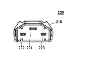
図1から図5に基づきプラグコネクタ200について説明する。図1は、プラグコネクタ200の斜視図であり、図2は上面図であり、図3は側面図であり、図4は底面図であり、図5は正面図である。
プラグコネクタ200は、絶縁体により形成されたカバー210と、3本のプラグ端子221、222、223を有している。カバー210のプラグ端子221、222、223が設けられている側と反対側には電源ケーブル230が接続されている。プラグ端子221はGND端子であり、プラグ端子222、223よりも長く形成されている。プラグ端子222、223は、コネクタ10の端子と電気的に接続されることにより電力が供給される端子である。尚、プラグコネクタ200のカバー210には、プラグ端子221、222、223の一部を覆うように形成された保護部211が設けられている。更にカバー210には、プラグコネクタ200がコネクタ10からはずれないようにするための開口部212が設けられている。 Theplug connector 200 will be described with reference to FIGS. 1 is a perspective view of the plug connector 200, FIG. 2 is a top view, FIG. 3 is a side view, FIG. 4 is a bottom view, and FIG. 5 is a front view.
Theplug connector 200 includes a cover 210 formed of an insulator and three plug terminals 221, 222, and 223. A power cable 230 is connected to the side of the cover 210 opposite to the side where the plug terminals 221, 222, and 223 are provided. The plug terminal 221 is a GND terminal and is longer than the plug terminals 222 and 223. The plug terminals 222 and 223 are terminals to which electric power is supplied by being electrically connected to the terminals of the connector 10. The cover 210 of the plug connector 200 is provided with a protection part 211 formed so as to cover a part of the plug terminals 221, 222, and 223. Further, the cover 210 is provided with an opening 212 for preventing the plug connector 200 from being detached from the connector 10.
プラグコネクタ200は、絶縁体により形成されたカバー210と、3本のプラグ端子221、222、223を有している。カバー210のプラグ端子221、222、223が設けられている側と反対側には電源ケーブル230が接続されている。プラグ端子221はGND端子であり、プラグ端子222、223よりも長く形成されている。プラグ端子222、223は、コネクタ10の端子と電気的に接続されることにより電力が供給される端子である。尚、プラグコネクタ200のカバー210には、プラグ端子221、222、223の一部を覆うように形成された保護部211が設けられている。更にカバー210には、プラグコネクタ200がコネクタ10からはずれないようにするための開口部212が設けられている。 The
The
次に、図6から図8に基づき本実施の形態におけるコネクタ10について説明する。図6は、コネクタ10の斜視図であり、図7は正面図であり、図8は側面図である。コネクタ10は筐体50に覆われており、プラグコネクタ200のプラグ端子221、222、223がそれぞれ挿入されるジャック開口部21、22、23と、プラグコネクタ200の保護部211が挿入される溝部31と、プラグコネクタ200とコネクタ10とが接続されている状態での電力供給を切り替えるためのスライド40が設けられている。スライド40は「ON」の位置または「OFF」の位置にスライドさせることが可能であり、スライド40をスライドさせることにより、コネクタ10を介した電力の供給を切り替えることができる。
Next, the connector 10 according to the present embodiment will be described with reference to FIGS. 6 is a perspective view of the connector 10, FIG. 7 is a front view, and FIG. 8 is a side view. The connector 10 is covered with a housing 50, and jack openings 21, 22, and 23 into which plug terminals 221, 222, and 223 of the plug connector 200 are respectively inserted, and a groove portion into which the protection part 211 of the plug connector 200 is inserted. 31 and a slide 40 for switching the power supply in a state where the plug connector 200 and the connector 10 are connected. The slide 40 can be slid to an “ON” position or an “OFF” position. By sliding the slide 40, power supply via the connector 10 can be switched.
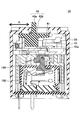
図9に基づき、コネクタ10の内部構造を説明する。図9は、コネクタ10の断面図である。コネクタ10は、スライド40の一部である操作部40aが筐体50に設けられた開口より外側に飛び出ている。筐体50の外側より操作部40aを矢印Aの方向に移動させることにより、筐体50の内部に設けられたスイッチ100を操作できる。
The internal structure of the connector 10 will be described with reference to FIG. FIG. 9 is a cross-sectional view of the connector 10. In the connector 10, an operation unit 40 a that is a part of the slide 40 protrudes outward from an opening provided in the housing 50. By moving the operation unit 40a in the direction of arrow A from the outside of the housing 50, the switch 100 provided inside the housing 50 can be operated.
スライド40は筐体50内に位置するスライド本体40bを有しており、スライド本体40bはスライドリンク41と接続されている。
The slide 40 has a slide main body 40b located in the housing 50, and the slide main body 40b is connected to the slide link 41.
スライドリンク41は、スライド40の移動に伴って矢印Aで示されるスライド方向と略平行に移動するものであって、L字状に形成されている。スライドリンク41の一方の端は、コンタクトスライド42の開口部42a内に入り込んでいる。尚、コンタクトスライド42は、後述するように、スライド40を矢印Aの右方向に動かすことにより、ボタン160を押下する。開口部42aは、スライドリンク41の移動方向、即ち、スライド方向に沿った細長い形状に形成されている。また、コンタクトスライド42には、スライド方向に対し略垂直下方向に伸びる接触部42b(図16図示)が設けられている。接触部42bの先端はスイッチ100のボタン160の上面に接触している。
The slide link 41 moves substantially parallel to the slide direction indicated by the arrow A as the slide 40 moves, and is formed in an L shape. One end of the slide link 41 enters the opening 42 a of the contact slide 42. The contact slide 42 pushes the button 160 by moving the slide 40 in the right direction of the arrow A as will be described later. The opening 42a is formed in an elongated shape along the moving direction of the slide link 41, that is, the sliding direction. Further, the contact slide 42 is provided with a contact portion 42b (shown in FIG. 16) extending in a substantially vertical downward direction with respect to the slide direction. The tip of the contact portion 42 b is in contact with the upper surface of the button 160 of the switch 100.
(スイッチ)
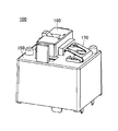
次に、スイッチ100について説明する。本実施の形態によるコネクタ10のスイッチ100は、電力の供給を切り替えるスイッチであって、電源スイッチとも称される。図10にスイッチ100の斜視図を示し、図11にスイッチ100の内部構造図を示す。図11に示されるように、スイッチ100は、固定部110の固定接点111と可動部120の可動接点121との接触・非接触により、電源の供給のオン、オフの制御を行なうことができるものである。 (switch)
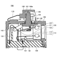
Next, theswitch 100 will be described. The switch 100 of the connector 10 according to the present embodiment is a switch for switching power supply, and is also referred to as a power switch. FIG. 10 shows a perspective view of the switch 100, and FIG. 11 shows an internal structure of the switch 100. As shown in FIG. As shown in FIG. 11, the switch 100 can perform on / off control of power supply by contact / non-contact between the fixed contact 111 of the fixed unit 110 and the movable contact 121 of the movable unit 120. It is.
次に、スイッチ100について説明する。本実施の形態によるコネクタ10のスイッチ100は、電力の供給を切り替えるスイッチであって、電源スイッチとも称される。図10にスイッチ100の斜視図を示し、図11にスイッチ100の内部構造図を示す。図11に示されるように、スイッチ100は、固定部110の固定接点111と可動部120の可動接点121との接触・非接触により、電源の供給のオン、オフの制御を行なうことができるものである。 (switch)
Next, the
固定部110は導電性材料により形成されており、固定接点111が固定バネ112の一方の端部に設けられている。尚、固定バネ112は、銅又は銅を含む合金からなる金属板等を折曲げることにより形成されており、固定接点111は銀と銅の合金により形成されている。固定バネ112の他方の端部はベースブロック130のベースブロック本体部131に固定されるとともに、固定バネ112の中程で支持部132により支持されている。
The fixed portion 110 is made of a conductive material, and a fixed contact 111 is provided at one end of the fixed spring 112. The fixed spring 112 is formed by bending a metal plate made of copper or an alloy containing copper, and the fixed contact 111 is formed of an alloy of silver and copper. The other end of the fixed spring 112 is fixed to the base block main body 131 of the base block 130 and is supported by the support portion 132 in the middle of the fixed spring 112.
可動部120は導電性材料により形成されており、固定接点111と接触する可動接点121が可動板122の一方の端部に設けられ、可動板122と可動バネ123とが接続されている。尚、可動板122及び可動バネ123は、銅又は銅を含む合金からなる金属板等を折曲げることにより形成されており、可動接点121は銀と銅の合金により形成されている。可動バネ123の他方の端部はベースブロック本体部131に固定されているが、可動バネ123は柔軟性を有しており、可動接点121を上下方向に動かすことが可能である。また、ベースブロック130の固定バネ112が固定されている部分と、可動バネ123が固定されている部分との間には、難燃性の樹脂材料等からなる絶縁壁133が設けられており、可動バネ123は、絶縁壁133を回り込むような形状で曲げられている。
The movable portion 120 is made of a conductive material, and a movable contact 121 that contacts the fixed contact 111 is provided at one end of the movable plate 122, and the movable plate 122 and the movable spring 123 are connected to each other. The movable plate 122 and the movable spring 123 are formed by bending a metal plate or the like made of copper or an alloy containing copper, and the movable contact 121 is formed of an alloy of silver and copper. The other end of the movable spring 123 is fixed to the base block main body 131. However, the movable spring 123 has flexibility and can move the movable contact 121 in the vertical direction. In addition, an insulating wall 133 made of a flame-retardant resin material or the like is provided between a portion where the fixed spring 112 of the base block 130 is fixed and a portion where the movable spring 123 is fixed, The movable spring 123 is bent in such a shape as to wrap around the insulating wall 133.
可動板122の上面は、カード140の接触部141と接触しており、可動板122の下面はカード140の接触部142と接触している。図11の状態で、回転軸143を中心にカード140を回転させることにより、可動板122が接触部141または接触部142と接触して可動板122に力が加わり、可動接点121を上下方向に移動させることができる。尚、接触部141及び接触部142の部分で可動板122が摺動するため、可動板122との間の摩擦抵抗を低減させるために接触部141及び接触部142の表面にフッ素樹脂等により形成された表面層を設けてもよい。
The upper surface of the movable plate 122 is in contact with the contact portion 141 of the card 140, and the lower surface of the movable plate 122 is in contact with the contact portion 142 of the card 140. In the state of FIG. 11, by rotating the card 140 around the rotation shaft 143, the movable plate 122 comes into contact with the contact portion 141 or the contact portion 142 to apply a force to the movable plate 122, and the movable contact 121 is moved in the vertical direction. Can be moved. Since the movable plate 122 slides at the contact portion 141 and the contact portion 142, the surface of the contact portion 141 and the contact portion 142 is formed of fluororesin or the like in order to reduce the frictional resistance with the movable plate 122. A surface layer may be provided.
固定部110及び可動部120は、ベースブロック130とケース150に囲まれた領域の内部に設置されている。また、カード140は、ケース150に設けられた開口151より外部に飛び出す突起部144と、ベースブロック130とケース150に囲まれた領域の内部に位置するカード本体145とを有している。接触部141及び接触部142もベースブロック130とケース150に囲まれた領域の内部に設けられている。また、カード140、ベースブロック130及びケース150は樹脂材料等の絶縁体材料により形成されている。
The fixed part 110 and the movable part 120 are installed in an area surrounded by the base block 130 and the case 150. Further, the card 140 has a protrusion 144 that protrudes to the outside from an opening 151 provided in the case 150, and a card main body 145 that is positioned inside a region surrounded by the base block 130 and the case 150. The contact part 141 and the contact part 142 are also provided in the area surrounded by the base block 130 and the case 150. Further, the card 140, the base block 130, and the case 150 are formed of an insulating material such as a resin material.
ケース150の外部には、カード140を回転させるために押下されるボタン160が設けられている。カード140は、突起部144の上部に設けられた接触部144aにおいてボタン160の内壁部161と接触している。尚、接触部144aは内壁部161の表面を摺動するため、接触部144aと内壁部161との間の摩擦抵抗を低減させるために、内壁部161の表面にフッ素樹脂等により形成された表面層を設けてもよい。また、ケース150の外部には、一方の端部がケース150に接続され、他方の端部がボタン160に接続された開離バネ170が設けられている。開離バネ170は、スライド40を図9の矢印Aの左方向に動かした際に、そのバネ力でボタン160を上方向に戻す。ボタン160が上方向に戻ることで、カード140が上方向に動く。
A button 160 that is pressed to rotate the card 140 is provided outside the case 150. The card 140 is in contact with the inner wall portion 161 of the button 160 at a contact portion 144 a provided on the upper portion of the projection portion 144. In addition, since the contact part 144a slides on the surface of the inner wall part 161, in order to reduce the frictional resistance between the contact part 144a and the inner wall part 161, the surface formed on the surface of the inner wall part 161 by a fluororesin or the like A layer may be provided. In addition, a release spring 170 having one end connected to the case 150 and the other end connected to the button 160 is provided outside the case 150. The release spring 170 returns the button 160 upward by the spring force when the slide 40 is moved in the left direction of the arrow A in FIG. When the button 160 returns upward, the card 140 moves upward.
(スイッチにおけるオン、オフ動作)
スイッチ100をオンにする場合には、コンタクトスライド42を一方の方向、図9の例では図示右方向にスライドさせる。これにより、スライドする接触部42bがボタン160を押下するため、ボタン160の内壁部161で接触部144aが接触しているカード140が回転軸143を中心に図11図示時計方向に回転する。これにより、接触部141と接触している可動板122に下方向に力が加えられ、可動接点121が下方に移動することで可動接点121と固定接点111とが接触し電力供給が可能となる。可動接点121と固定接点111とが接触した状態を図12に示す。尚、コンタクトスライド42の接触部42bによりボタン160が図12図示の位置に維持されるため、可動接点121と固定接点111との接触が維持される。 (Switch on / off operation)
When theswitch 100 is turned on, the contact slide 42 is slid in one direction, in the example shown in FIG. As a result, the sliding contact portion 42 b presses the button 160, so that the card 140 in contact with the contact portion 144 a on the inner wall portion 161 of the button 160 rotates about the rotation shaft 143 in the clockwise direction in FIG. 11. As a result, a downward force is applied to the movable plate 122 that is in contact with the contact portion 141, and the movable contact 121 moves downward, so that the movable contact 121 and the fixed contact 111 come into contact with each other, and power can be supplied. . FIG. 12 shows a state where the movable contact 121 and the fixed contact 111 are in contact with each other. Since the button 160 is maintained at the position shown in FIG. 12 by the contact portion 42b of the contact slide 42, the contact between the movable contact 121 and the fixed contact 111 is maintained.
スイッチ100をオンにする場合には、コンタクトスライド42を一方の方向、図9の例では図示右方向にスライドさせる。これにより、スライドする接触部42bがボタン160を押下するため、ボタン160の内壁部161で接触部144aが接触しているカード140が回転軸143を中心に図11図示時計方向に回転する。これにより、接触部141と接触している可動板122に下方向に力が加えられ、可動接点121が下方に移動することで可動接点121と固定接点111とが接触し電力供給が可能となる。可動接点121と固定接点111とが接触した状態を図12に示す。尚、コンタクトスライド42の接触部42bによりボタン160が図12図示の位置に維持されるため、可動接点121と固定接点111との接触が維持される。 (Switch on / off operation)
When the
また、スイッチをオフにする場合には、後述するように、コンタクトスライド42をスイッチオン時とは反対の方向、図9図示左側に移動させる。接触部42bが移動してボタンを押下していない状態になると、開離バネ170のバネ力によりボタン160が上方に移動する。ボタン160の上方への移動に応じて、カード140がボタン160により引き上げられ回転軸143を中心に回転して、接触部142に接触する可動板122に上方向に力が加わる。図20に示すカード140の上部に設けられた引っ掛け部146がボタン160に引っかかるため、ボタン160が上に動くことにより、カード140が引き上げられる。このように可動板122に加えられた上方向の力により可動接点121が上方に移動し、図11に示すように可動接点121と固定接点111とを離すことができ、電力の供給を停止することができる。この際、可動接点121と固定接点111との間でアークが発生する場合があるため、磁力によりアークを飛ばすことができるように、可動接点121と固定接点111との接触位置の近傍には、アークの発生する方向に対して略垂直方向の磁界を発生させる不図示の永久磁石が設けられている。
Further, when the switch is turned off, the contact slide 42 is moved in the direction opposite to that when the switch is turned on, as shown later, in the left side of FIG. When the contact part 42b moves and does not press the button, the button 160 moves upward by the spring force of the breaking spring 170. As the button 160 moves upward, the card 140 is pulled up by the button 160 and rotates around the rotation shaft 143, and an upward force is applied to the movable plate 122 contacting the contact portion 142. Since the hooking portion 146 provided on the upper portion of the card 140 shown in FIG. 20 is hooked on the button 160, the card 140 is pulled up by moving the button 160 upward. Thus, the movable contact 121 is moved upward by the upward force applied to the movable plate 122, so that the movable contact 121 and the fixed contact 111 can be separated as shown in FIG. 11, and the power supply is stopped. be able to. At this time, since an arc may be generated between the movable contact 121 and the fixed contact 111, in the vicinity of the contact position between the movable contact 121 and the fixed contact 111, the arc can be blown by a magnetic force. A permanent magnet (not shown) that generates a magnetic field substantially perpendicular to the direction in which the arc is generated is provided.
スイッチ100で電力の供給を遮断する際には、可動バネ123のバネ力を用いて可動接点121を上方に移動させるのではなく、ケース150の外部に設けられた開離バネ170によってボタン160を押し上げることにより、カード140を上方に移動させて、スイッチ100をオフ状態にする。このため、可動バネ123が可動接点121を固定接点111から引き離す程度の力を有していない場合においてもスイッチをオフにできる。また、熱により可動バネ123の一部が溶けてしまいバネとしての機能が失われた場合においても、可動バネ123のバネ力を用いることなく、開離バネ170のバネ性によりスイッチをオフ状態にすることができ電力の供給を確実に遮断することができる。また、開離バネ170はケース150の外部に設置されているため、ケース150内部で発生する熱の影響を受けることはない。
When the power supply is cut off by the switch 100, the movable contact 121 is not moved upward by using the spring force of the movable spring 123, but the button 160 is moved by the release spring 170 provided outside the case 150. By pushing up, the card 140 is moved upward and the switch 100 is turned off. For this reason, even when the movable spring 123 does not have enough force to pull the movable contact 121 away from the fixed contact 111, the switch can be turned off. Further, even when a part of the movable spring 123 is melted by heat and the function as a spring is lost, the switch is turned off by the spring property of the breaking spring 170 without using the spring force of the movable spring 123. The supply of electric power can be cut off reliably. Further, since the release spring 170 is installed outside the case 150, it is not affected by the heat generated inside the case 150.
また、ベースブロック130の固定バネ112が固定されている部分と、可動バネ123が固定されている部分との間に絶縁壁133が設けられている。固定部110と可動部120との溶解が進行しても、固定部110の溶解した部分と、可動部120の溶解した部分とが絶縁壁133により分離される。よって、固定部110と可動部120とが溶解してくっついた状態のままとなって電流が流れ続けてしまうことを防ぐことができる。
Further, an insulating wall 133 is provided between a portion of the base block 130 where the fixed spring 112 is fixed and a portion where the movable spring 123 is fixed. Even if dissolution of the fixed part 110 and the movable part 120 proceeds, the dissolved part of the fixed part 110 and the dissolved part of the movable part 120 are separated by the insulating wall 133. Therefore, it is possible to prevent the current from continuing to flow while the fixed portion 110 and the movable portion 120 remain melted.
(コネクタにおけるオン、オフ動作)
次に、本実施の形態によるコネクタ10のオン、オフ動作について説明する。図13に示すコネクタ10とプラグコネクタ200が離れている状態から、図14に示すようにコネクタ10とプラグコネクタ200とを嵌合させる。そして、図14の状態でコネクタ10のオン、オフを切り替えることにより、スイッチ100をオン、オフすることができる。具体的には、スライド40の操作部40aを図14に示す「OFF」の位置から図15に示す「ON」の位置にスライドさせる。スライド40のスライド操作により、接触部42bによってボタン160上面の上段部165が押されて、ボタン160が下がり、スイッチ100が図9に示すオフ状態から図16に示すオン状態となる。尚、スイッチをオンからオフにする場合には、操作部40aを図15に示す「ON」側から図14に示す「OFF」側にスライドさせる。 (ON / OFF operation at the connector)
Next, the on / off operation of theconnector 10 according to the present embodiment will be described. From the state where the connector 10 and the plug connector 200 shown in FIG. 13 are separated, the connector 10 and the plug connector 200 are fitted as shown in FIG. Then, the switch 100 can be turned on and off by switching the connector 10 on and off in the state of FIG. Specifically, the operation unit 40a of the slide 40 is slid from the “OFF” position shown in FIG. 14 to the “ON” position shown in FIG. By the slide operation of the slide 40, the upper portion 165 of the upper surface of the button 160 is pushed by the contact portion 42b, the button 160 is lowered, and the switch 100 is changed from the off state shown in FIG. 9 to the on state shown in FIG. When the switch is turned from on to off, the operation unit 40a is slid from the “ON” side shown in FIG. 15 to the “OFF” side shown in FIG.
次に、本実施の形態によるコネクタ10のオン、オフ動作について説明する。図13に示すコネクタ10とプラグコネクタ200が離れている状態から、図14に示すようにコネクタ10とプラグコネクタ200とを嵌合させる。そして、図14の状態でコネクタ10のオン、オフを切り替えることにより、スイッチ100をオン、オフすることができる。具体的には、スライド40の操作部40aを図14に示す「OFF」の位置から図15に示す「ON」の位置にスライドさせる。スライド40のスライド操作により、接触部42bによってボタン160上面の上段部165が押されて、ボタン160が下がり、スイッチ100が図9に示すオフ状態から図16に示すオン状態となる。尚、スイッチをオンからオフにする場合には、操作部40aを図15に示す「ON」側から図14に示す「OFF」側にスライドさせる。 (ON / OFF operation at the connector)
Next, the on / off operation of the
スイッチ100がオンとなると、コネクタ10に設けられた不図示のフックが図4に示されるプラグコネクタ200の開口部212に入り込む。フックの入り込みによって、コネクタ10とプラグコネクタ200との嵌合状態が維持され、プラグコネクタ200の抜けを防止できる。また、スイッチ100がオフとなると、フックが開口部212からはずれ、コネクタ10からプラグコネクタ200を外すことができる。
When the switch 100 is turned on, a hook (not shown) provided in the connector 10 enters the opening 212 of the plug connector 200 shown in FIG. By fitting the hook, the fitting state between the connector 10 and the plug connector 200 is maintained, and the plug connector 200 can be prevented from coming off. Further, when the switch 100 is turned off, the hook is detached from the opening 212 and the plug connector 200 can be detached from the connector 10.
(双子接点のスイッチ)
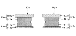
ところで、コネクタ10のスイッチに、スイッチを構成する固定部と可動部とが各々2つ設けられる場合がある。図17に示す例では、第1の固定部910a及び第2の固定部910bと、第1の可動部920a及び第2の可動部920bとの2つの組が設けられている。 (Twin contact switch)
By the way, the switch of theconnector 10 may be provided with two each of a fixed part and a movable part constituting the switch. In the example shown in FIG. 17, two sets of a first fixed portion 910a and a second fixed portion 910b, and a first movable portion 920a and a second movable portion 920b are provided.
ところで、コネクタ10のスイッチに、スイッチを構成する固定部と可動部とが各々2つ設けられる場合がある。図17に示す例では、第1の固定部910a及び第2の固定部910bと、第1の可動部920a及び第2の可動部920bとの2つの組が設けられている。 (Twin contact switch)
By the way, the switch of the
第1の固定部910aは、第1の固定接点911a及び第1の固定バネ912aを有しており、第2の固定部910bは第2の固定接点911b及び第2の固定バネ912bを有している。第1の可動部920aは、第1の可動接点921a及び第1の可動板922aを有しており、第2の可動部920bは、第2の可動接点921b及び第2の可動板922bを有している。
The first fixed portion 910a has a first fixed contact 911a and a first fixed spring 912a, and the second fixed portion 910b has a second fixed contact 911b and a second fixed spring 912b. ing. The first movable portion 920a has a first movable contact 921a and a first movable plate 922a, and the second movable portion 920b has a second movable contact 921b and a second movable plate 922b. is doing.
第1の固定部910aと第1の可動部920aとにより第1のスイッチ901aが形成され、第2の固定部910bと第2の可動部920bとにより第2のスイッチ901bが形成される。図17に示すスイッチでは、第1のスイッチ901aと第2のスイッチ901bの双方がオンとなった場合にスイッチがオンとなり、第1のスイッチ901aまたは第2のスイッチ901bのうちのいずれか一方がオフとなったときにスイッチがオフとなる。尚、第1のスイッチ901aは、第1の固定接点911aと第1の可動接点921aとが接触することによりオンとなり、第1の固定接点911aが第1の可動接点921aと離れることによりオフとなる。同様に、第2のスイッチ901bは、第2の固定接点911bと第2の可動接点921bとが接触することによりオンとなり、第2の固定接点911bが第2の可動接点921bと離れることによりオフとなる。
The first fixed portion 910a and the first movable portion 920a form a first switch 901a, and the second fixed portion 910b and the second movable portion 920b form a second switch 901b. In the switch illustrated in FIG. 17, the switch is turned on when both the first switch 901a and the second switch 901b are turned on, and either the first switch 901a or the second switch 901b is turned on. The switch turns off when it turns off. The first switch 901a is turned on when the first fixed contact 911a and the first movable contact 921a come into contact with each other, and is turned off when the first fixed contact 911a is separated from the first movable contact 921a. Become. Similarly, the second switch 901b is turned on when the second fixed contact 911b and the second movable contact 921b come into contact with each other, and is turned off when the second fixed contact 911b is separated from the second movable contact 921b. It becomes.
このような構造のスイッチでは、図18に示すように、第1の固定接点911aと第1の可動接点921aとの間、または第2の固定接点911bと第2の可動接点921bとの間に異物970が存在している場合には、固定接点と可動接点との導通が妨げられ、スイッチがオンにならなくなるため、電力を供給することができない。
In the switch having such a structure, as shown in FIG. 18, between the first fixed contact 911a and the first movable contact 921a or between the second fixed contact 911b and the second movable contact 921b. When the foreign object 970 exists, the continuity between the fixed contact and the movable contact is hindered and the switch is not turned on, so that power cannot be supplied.
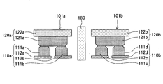
次に、本実施の形態によるスイッチ100について説明する。スイッチ100が有する第1のスイッチ101aと第2のスイッチ101bの固定部あるいは可動部は双子接点により構成されている。図19及び図20に示す例では、第1の固定部110a及び第2の固定部110bが双子接点となっている。
Next, the switch 100 according to this embodiment will be described. The fixed part or the movable part of the first switch 101a and the second switch 101b included in the switch 100 is configured by twin contacts. In the example shown in FIGS. 19 and 20, the first fixed portion 110a and the second fixed portion 110b are twin contacts.
第1の固定部110aは、第1の固定接点111aと第2の固定接点111bの2つの固定接点を有している。第1の固定接点111aは第1の固定バネ112aに設置されており、第2の固定接点111bは第2の固定バネ112bに設置されている。第2の固定部110bは、第3の固定接点111cと第4の固定接点111dの2つの固定接点を有している。第3の固定接点111cは第3の固定バネ112cに設置されており、第4の固定接点111dは第4の固定バネ112dに設置されている。
The first fixed portion 110a has two fixed contacts, a first fixed contact 111a and a second fixed contact 111b. The first fixed contact 111a is installed on the first fixed spring 112a, and the second fixed contact 111b is installed on the second fixed spring 112b. The second fixed portion 110b has two fixed contacts, a third fixed contact 111c and a fourth fixed contact 111d. The third fixed contact 111c is installed on the third fixed spring 112c, and the fourth fixed contact 111d is installed on the fourth fixed spring 112d.
尚、図20に示すように、第1の固定バネ112aと第2の固定バネ112bとは電気的に接続され、一体に形成されている固定バネに溝を設けることにより第1の固定バネ112aと第2の固定バネ112bとが分離されている。同様に、一体に形成されている固定バネに溝を設けることにより、第3の固定バネ112cと第4の固定バネ112dとが分離されるように形成されている。
As shown in FIG. 20, the first fixed spring 112a and the second fixed spring 112b are electrically connected, and the first fixed spring 112a is formed by providing a groove in the integrally formed fixed spring. And the second fixing spring 112b are separated. Similarly, the third fixed spring 112c and the fourth fixed spring 112d are separated from each other by providing a groove in the integrally formed fixed spring.
第1の可動部120aは単一の第1の可動接点121aを有している。第1の可動接点121aは第1の可動板122aに設置されており、第1の可動板122aは第1の可動バネ123aに接続されている。同様に、第2の可動部120bは単一の第2の可動接点121bを有している。第2の可動接点121bは第2の可動板122bに設置されており、第2の可動板122bは第2の可動バネ123bに接続されている。
The first movable part 120a has a single first movable contact 121a. The first movable contact 121a is installed on the first movable plate 122a, and the first movable plate 122a is connected to the first movable spring 123a. Similarly, the second movable part 120b has a single second movable contact 121b. The second movable contact 121b is installed on the second movable plate 122b, and the second movable plate 122b is connected to the second movable spring 123b.
本実施の形態では、第1の固定部110aと第1の可動部120aとにより第1のスイッチ101aが形成されている。また、第2の固定部11bと第2の可動部120bとにより第2のスイッチ101bが形成されている。
In the present embodiment, the first switch 101a is formed by the first fixed portion 110a and the first movable portion 120a. The second fixed portion 11b and the second movable portion 120b form a second switch 101b.
スイッチ100は、第1のスイッチ101aと第2のスイッチ101bの双方がオンとなった場合にオンとなり、第1のスイッチ101aまたは第2のスイッチ101bのうちのいずれかがオフの場合にオフとなる。
The switch 100 is turned on when both the first switch 101a and the second switch 101b are turned on, and is turned off when either the first switch 101a or the second switch 101b is turned off. Become.
尚、第1のスイッチ101aは双子接点のスイッチであるため、第1の固定接点111aまたは第2の固定接点111bの少なくともいずれか一方と、第1の可動接点121aとが接触することにより第1のスイッチ101aがオンとなる。同様に、第2のスイッチ101bも双子接点のスイッチであるため、第3の固定接点111cまたは第4の固定接点111dの少なくともいずれか一方と第2の可動接点121bとが接触することにより第2のスイッチ101bがオンとなる。
Since the first switch 101a is a twin contact switch, at least one of the first fixed contact 111a or the second fixed contact 111b and the first movable contact 121a come into contact with each other. The switch 101a is turned on. Similarly, since the second switch 101b is also a twin contact switch, at least one of the third fixed contact 111c and the fourth fixed contact 111d and the second movable contact 121b come into contact with each other, so that the second switch 101b is a second contact. The switch 101b is turned on.
従って、図21に示すように、第1の固定接点111aと第1の可動接点121aとの間に異物70が存在している場合であっても、第2の固定接点111bと第1の可動接点121aとが接触していれば第1のスイッチ101aがオンとなり、第2のスイッチ101bもオンとなることでスイッチ100をオンにできる。
Therefore, as shown in FIG. 21, even if the foreign object 70 exists between the first fixed contact 111a and the first movable contact 121a, the second fixed contact 111b and the first movable contact 111a. If the contact point 121a is in contact, the first switch 101a is turned on, and the second switch 101b is also turned on, whereby the switch 100 can be turned on.
本実施の形態では、第1のスイッチ101aと第2のスイッチ101bとの間に永久磁石180が設置されている。永久磁石180を第1のスイッチ101aと第2のスイッチ101bとの間に設置することにより、固定接点と可動接点との間に発生したアークを永久磁石180により生じた磁界により吹き飛ばすことができる。例えば、図22に示されるように、第1のスイッチ101aと第2のスイッチ101bとの間に設置された永久磁石180により一点鎖線矢印に示される方向に磁界が発生するため、破線矢印に示される方向に流れる電流により接点間に生じたアークを二点鎖線矢印に示す方向に吹き飛ばすことができる。
In this embodiment, a permanent magnet 180 is installed between the first switch 101a and the second switch 101b. By installing the permanent magnet 180 between the first switch 101a and the second switch 101b, the arc generated between the fixed contact and the movable contact can be blown away by the magnetic field generated by the permanent magnet 180. For example, as shown in FIG. 22, a magnetic field is generated in the direction indicated by the one-dot chain line arrow by the permanent magnet 180 installed between the first switch 101a and the second switch 101b. The arc generated between the contacts due to the current flowing in the direction can be blown off in the direction indicated by the two-dot chain line arrow.
ところで、図17に示すスイッチの場合、第1のスイッチ101aと第2のスイッチ101bとは必ずしも同時にはオンとならず、第1のスイッチ901a又は第2のスイッチ901bのうちのいずれか一方のスイッチが先にオンとなり、他方のスイッチが後でオンとなる可能性もある。この場合、後でオンとなるスイッチがオンとなることにより、スイッチがオンとなる。従って、後にオンとなるスイッチの接点間に、チャタリング等に起因する突入電流によるアークが発生する場合があり、後でオンとなるスイッチの接点表面にダメージを与え、導通不良の原因となる。
By the way, in the case of the switch shown in FIG. 17, the first switch 101a and the second switch 101b are not necessarily turned on at the same time, and either the first switch 901a or the second switch 901b. May be turned on first and the other switch turned on later. In this case, when the switch that is turned on later is turned on, the switch is turned on. Therefore, an arc due to an inrush current due to chattering or the like may occur between the contact points of the switch that is turned on later, causing damage to the contact surface of the switch that is turned on later, causing a conduction failure.
図17に示すスイッチの場合、図23に示すように、第1のスイッチ901aが先にオンとなり、第2のスイッチ901bが後でオンとなる場合と、図24に示すように、第2のスイッチ901bが先にオンとなり、第1のスイッチ901aが後でオンとなる場合との2通りが考えられる。よって、一回のオン動作時に、第1の固定接点911aと第1の可動接点921aとの間に突入電流が流れる確率と、第2の固定接点111bと第2の可動接点921bとの間に突入電流が流れる確率は、各々約1/2であると考えられる。
In the case of the switch shown in FIG. 17, as shown in FIG. 23, the first switch 901a is turned on first, and the second switch 901b is turned on later. There are two possible cases: the switch 901b is turned on first and the first switch 901a is turned on later. Therefore, the probability that an inrush current flows between the first fixed contact 911a and the first movable contact 921a and the second fixed contact 111b and the second movable contact 921b during one ON operation. The probability that an inrush current flows is considered to be about ½ each.
これに対し、本実施の形態におけるスイッチ100では、第1の固定接点111a、第2の固定接点111b、第3の固定接点111c、第4の固定接点111dと4つの固定接点が設けられている。スイッチ100では、第1のスイッチ101aまたは第2のスイッチ101bのうち後でオンとなるスイッチの接点の先に接触する固定接点と可動接点との間において突入電流が生じる。
On the other hand, the switch 100 in the present embodiment is provided with the first fixed contact 111a, the second fixed contact 111b, the third fixed contact 111c, and the fourth fixed contact 111d, and four fixed contacts. . In the switch 100, an inrush current is generated between the fixed contact and the movable contact that come in contact with the tip of the switch that is turned on later in the first switch 101a or the second switch 101b.
図25に示すように、第1の固定接点111aまたは第2の固定接点111bの少なくともいずれか一方が第1の可動接点121aと接触している状態では、第3の固定接点111cが第4の固定接点111dよりも先に第2の可動接点121bと接触する場合には、第3の固定接点111cと第2の可動接点121bとの間で突入電流が流れる。
As shown in FIG. 25, when at least one of the first fixed contact 111a and the second fixed contact 111b is in contact with the first movable contact 121a, the third fixed contact 111c is the fourth fixed contact 111c. When the second movable contact 121b is contacted before the fixed contact 111d, an inrush current flows between the third fixed contact 111c and the second movable contact 121b.
また、図26に示すように、第1の固定接点111aまたは第2の固定接点111bの少なくともいずれか一方が第1の可動接点121aと接触しているときに、第4の固定接点111dが第3の固定接点111cよりも先に第2の可動接点121bと接触する場合には、第4の固定接点111dと第2の可動接点121bとの間で突入電流が流れる。
Further, as shown in FIG. 26, when at least one of the first fixed contact 111a and the second fixed contact 111b is in contact with the first movable contact 121a, the fourth fixed contact 111d is the first fixed contact 111d. When the second movable contact 121b comes into contact with the third fixed contact 111c prior to the third fixed contact 111c, an inrush current flows between the fourth fixed contact 111d and the second movable contact 121b.
また、図27に示すように、第3の固定接点111cと第4の固定接点111dとの少なくともいずれか一方が第2の可動接点121dと接触している場合、第1の固定接点111aが第2の固定接点111bよりも先に第1の可動接点121aと接触するときには、第1の固定接点111aと第1の可動接点121aとの間で突入電流が流れる。
In addition, as shown in FIG. 27, when at least one of the third fixed contact 111c and the fourth fixed contact 111d is in contact with the second movable contact 121d, the first fixed contact 111a is the first fixed contact 111a. When contacting the first movable contact 121a before the second fixed contact 111b, an inrush current flows between the first fixed contact 111a and the first movable contact 121a.
また、図28に示すように、第3の固定接点111cまたは第4の固定接点111dの少なくともいずれか一方が第2の可動接点121dと接触している場合に、第2の固定接点111bが第1の固定接点111aよりも先に第1の可動接点121aと接触するときには、第2の固定接点111bと第1の可動接点121aとの間で突入電流が流れる。
As shown in FIG. 28, when at least one of the third fixed contact 111c or the fourth fixed contact 111d is in contact with the second movable contact 121d, the second fixed contact 111b is When the first movable contact 111a comes into contact with the first movable contact 121a before the first fixed contact 111a, an inrush current flows between the second fixed contact 111b and the first movable contact 121a.
従って、一回のオン動作において、それぞれの固定接点に突入電流が流れる確率は1/4となると考えられる。このように、本実施の形態では、各々の固定接点に突入電流が流れる確率が図17に示す例と比べ半分になるため、同じオン回数であっても、各々の固定接点に与えられるダメージを減らすことができ、コネクタを長寿命化させることができる。
Therefore, it is considered that the probability that an inrush current flows to each fixed contact in one ON operation is 1/4. In this way, in this embodiment, the probability that an inrush current flows to each fixed contact is half that of the example shown in FIG. 17, so that even if the number of ON times is the same, the damage given to each fixed contact is reduced. This can reduce the life of the connector.
尚、上記ではスイッチがオフからオンになる際に発生する突入電流によるアークの場合について説明したが、スイッチがオンからオフになる際に発生するアークについても同様である。
In the above description, the case of an arc caused by an inrush current that occurs when the switch is turned on from off has been described.
スイッチがオンからオフとなる場合、スイッチ100では、第1のスイッチ101aまたは第2のスイッチ101bの先にオフとなるスイッチの接点のうち、後で離れる固定接点と可動接点との間にアークが生じる。
When the switch is turned off from on, the switch 100 generates an arc between the fixed contact and the movable contact that are separated later among the contact points of the switch that is turned off before the first switch 101a or the second switch 101b. Arise.
具体的には、図29に示すように、第1の固定接点111aと第2の固定接点111bのうちの少なくともいずれか一方が第1の可動接点121aと接触している状態で、第3の固定接点111cが第4の固定接点111dよりも後に第2の可動接点121bから離れる場合には、第3の固定接点111cと第2の可動接点121bとの間でアークが発生する。
Specifically, as shown in FIG. 29, in a state where at least one of the first fixed contact 111a and the second fixed contact 111b is in contact with the first movable contact 121a, When the fixed contact 111c moves away from the second movable contact 121b after the fourth fixed contact 111d, an arc is generated between the third fixed contact 111c and the second movable contact 121b.
また、図30に示すように、第1の固定接点111aと第2の固定接点111bの少なくとも一方が第1の可動接点121aと接触している場合において、第4の固定接点111dが第3の固定接点111cよりも後に第2の可動接点121bから離れる場合には、第4の固定接点111dと第2の可動接点121bとの間でアークが発生する。
Further, as shown in FIG. 30, when at least one of the first fixed contact 111a and the second fixed contact 111b is in contact with the first movable contact 121a, the fourth fixed contact 111d is the third fixed contact 111a. When leaving the second movable contact 121b after the fixed contact 111c, an arc is generated between the fourth fixed contact 111d and the second movable contact 121b.
また、図31に示すように、第3の固定接点111cと第4の固定接点111dの少なくとも一方が第2の可動接点121dと接触している場合において、第1の固定接点111aが第2の固定接点111bよりも後に第1の可動接点121aから離れる場合には、第1の固定接点111aと第1の可動接点121aとの間でアークが発生する。
Further, as shown in FIG. 31, when at least one of the third fixed contact 111c and the fourth fixed contact 111d is in contact with the second movable contact 121d, the first fixed contact 111a is the second fixed contact 111a. When leaving the first movable contact 121a after the fixed contact 111b, an arc is generated between the first fixed contact 111a and the first movable contact 121a.
また、図32に示すように、第3の固定接点111cと第4の固定接点111dの少なくとも一方が第2の可動接点121dと接触している場合、第2の固定接点111bが第1の固定接点111aよりも後に第1の可動接点121aから離れる場合には、第2の固定接点111bと第1の可動接点121aとの間でアークが発生する。
Further, as shown in FIG. 32, when at least one of the third fixed contact 111c and the fourth fixed contact 111d is in contact with the second movable contact 121d, the second fixed contact 111b is the first fixed contact. When leaving the first movable contact 121a after the contact 111a, an arc is generated between the second fixed contact 111b and the first movable contact 121a.
従って、一回のオフ動作時に各々の固定接点でアークの発生する確率は1/4となる。このように一つの固定接点でアークの発生する確率が図17の例と比べ半分となるため、同じオフ回数であっても、各々の固定接点に与えられるダメージを減らすことができ、長寿命化させることができる。
Therefore, the probability that an arc will occur at each fixed contact during one off operation is 1/4. As described above, since the probability of occurrence of an arc at one fixed contact is halved compared to the example of FIG. 17, even if the number of off times is the same, the damage given to each fixed contact can be reduced, and the life is extended. Can be made.
〔第2の実施の形態〕
次に、第2の実施の形態について説明する。本実施の形態は、一つのスイッチに可動接点を複数設けた構造のものである。 [Second Embodiment]
Next, a second embodiment will be described. In the present embodiment, a plurality of movable contacts are provided in one switch.
次に、第2の実施の形態について説明する。本実施の形態は、一つのスイッチに可動接点を複数設けた構造のものである。 [Second Embodiment]
Next, a second embodiment will be described. In the present embodiment, a plurality of movable contacts are provided in one switch.
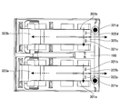
図33に示す本実施の形態によるスイッチは、各々の可動部が双子接点により形成された第1のスイッチ301aと第2のスイッチ301bとを有している。図34及び図35に示すように、スイッチには、第1の固定部310a及び第2の固定部310bと、第1の可動部320a及び第2の可動部320bとが設けられている。
The switch according to this embodiment shown in FIG. 33 has a first switch 301a and a second switch 301b in which each movable part is formed by a twin contact. As shown in FIGS. 34 and 35, the switch is provided with a first fixed portion 310a and a second fixed portion 310b, and a first movable portion 320a and a second movable portion 320b.
第1の固定部310aは、第1固定バネ312aに設置された第1の固定接点311aを有している。第2の固定部310bは、第2固定バネ312bに設置された第2の固定接点311bを有している。
The first fixed portion 310a has a first fixed contact 311a installed on the first fixed spring 312a. The second fixed portion 310b has a second fixed contact 311b installed on the second fixed spring 312b.
第1の可動部320aは、第1の可動接点321aと第2の可動接点321bとを有している。第1の可動接点321aは第1の可動板322aに設置されており、第2の可動接点321bは第2の可動板322bに設置されている。第1の可動板322a及び第2の可動板322bは、第1の可動バネ323aに接続されている。
The first movable part 320a has a first movable contact 321a and a second movable contact 321b. The first movable contact 321a is installed on the first movable plate 322a, and the second movable contact 321b is installed on the second movable plate 322b. The first movable plate 322a and the second movable plate 322b are connected to the first movable spring 323a.
第2の可動部320bは、第3の可動接点321cと第4の可動接点321dとを有している。第3の可動接点321cは第3の可動板322cに設置されており、第4の可動接点321dは第4の可動板322dに設置されている。第3の可動板322c及び第4の可動板322dは、第2の可動バネ323bに接続されている。
The second movable portion 320b has a third movable contact 321c and a fourth movable contact 321d. The third movable contact 321c is installed on the third movable plate 322c, and the fourth movable contact 321d is installed on the fourth movable plate 322d. The third movable plate 322c and the fourth movable plate 322d are connected to the second movable spring 323b.
本実施の形態では、第1の固定部310aと第1の可動部320aにより第1のスイッチ301aが形成されている。また、第2の固定部310bと第2の可動部320bにより第2のスイッチ301bが形成されている。
In the present embodiment, the first switch 301a is formed by the first fixed portion 310a and the first movable portion 320a. In addition, the second switch 301b is formed by the second fixed portion 310b and the second movable portion 320b.
尚、第1のスイッチ301aは双子接点のスイッチであり、第1の固定接点311aと、第1の可動接点321aまたは第2の可動接点321bのうちの少なくとも一方とが接触することによりオンとなり、第1の固定接点311aが、第1の可動接点321a及び第2の可動接点321bの双方から離れることによりオフとなる。同様に、第2のスイッチ301bも双子接点のスイッチであり、第2の固定接点311bと第3の可動接点321cまたは第4の可動接点321dのうちの少なくとも一方とが接触することによりオンとなり、第2の固定接点311bが、第3の可動接点321c及び第4の可動接点321dの双方から離れることによりオフとなる。
The first switch 301a is a twin contact switch, and is turned on when the first fixed contact 311a and at least one of the first movable contact 321a or the second movable contact 321b come into contact with each other. The first fixed contact 311a is turned off when it is separated from both the first movable contact 321a and the second movable contact 321b. Similarly, the second switch 301b is also a twin contact switch, and is turned on when the second fixed contact 311b and at least one of the third movable contact 321c or the fourth movable contact 321d come into contact with each other, The second fixed contact 311b is turned off by moving away from both the third movable contact 321c and the fourth movable contact 321d.
また、本実施の形態においては、第1のスイッチ301aと第2のスイッチ301bとの間に永久磁石180が設置されている。永久磁石180の磁界により、固定接点と可動接点との間に発生したアークを吹き飛ばすことができる。例えば、図35に示されるように、第1のスイッチ301aと第2のスイッチ301bとの間に設置された永久磁石180により、一点鎖線矢印に示される方向に磁界が発生し、破線矢印に示される方向に流れる電流により接点間に生じたアークを二点鎖線矢印に示す方向に吹き飛ばすことができる。
In this embodiment, a permanent magnet 180 is installed between the first switch 301a and the second switch 301b. The arc generated between the fixed contact and the movable contact can be blown off by the magnetic field of the permanent magnet 180. For example, as shown in FIG. 35, the permanent magnet 180 installed between the first switch 301a and the second switch 301b generates a magnetic field in the direction indicated by the one-dot chain line arrow, and is indicated by the dashed arrow. The arc generated between the contacts due to the current flowing in the direction can be blown off in the direction indicated by the two-dot chain line arrow.
尚、上記以外の内容については、第1の実施の形態と同様である。
The contents other than the above are the same as those in the first embodiment.
以上、本発明の実施に係る形態について説明したが、上記内容は、発明の内容を限定するものではない。
As mentioned above, although the form which concerns on implementation of this invention was demonstrated, the said content does not limit the content of invention.
本国際出願は、2015年2月6日に出願された日本国特許出願2015-022619号に基づく優先権を主張するものであり、2015-022619号の全内容をここに本国際出願に援用する。
This international application claims priority based on Japanese Patent Application No. 2015-022619 filed on February 6, 2015, the entire contents of which are hereby incorporated herein by reference. .
10 コネクタ
21、22、23 ジャック開口部
40a 操作部
41 スライドリンク
42 コンタクトスライド
101a 第1のスイッチ
101b 第2のスイッチ
110 固定部
110a 第1の固定部
110b 第2の固定部
111 固定接点
111a 第1の固定接点
111b 第2の固定接点
111c 第3の固定接点
111d 第4の固定接点
112 固定バネ
112a 第1の固定バネ
112b 第2の固定バネ
112c 第3の固定バネ
112d 第4の固定バネ
120 可動部
120a 第1の可動部
120b 第2の可動部
121 可動接点
121a 第1の可動接点
121b 第2の可動接点
122 可動板
122a 第1の可動板
122b 第2の可動板
123 可動バネ
123a 第1の可動バネ
123b 第2の可動バネ
130 ベースブロック
140 カード
143 回転軸
144 突起部
160 ボタン
170 開離バネ
180 永久磁石
200 プラグコネクタ
221、222、223 プラグ端子 10 connector 21, 22, 23 jack opening 40a operation unit 41 slide link 42 contact slide 101a first switch 101b second switch 110 fixed unit 110a first fixed unit 110b second fixed unit 111 fixed contact 111a first Fixed contact 111b second fixed contact 111c third fixed contact 111d fourth fixed contact 112 fixed spring 112a first fixed spring 112b second fixed spring 112c third fixed spring 112d fourth fixed spring 120 movable Part 120a first movable part 120b second movable part 121 movable contact 121a first movable contact 121b second movable contact 122 movable plate 122a first movable plate 122b second movable plate 123 movable spring 123a first Movable spring 123b Second movable bar 130 base block 140 card 143 rotary shaft 144 protruding portions 160 button 170 separable spring 180 permanent magnet 200 plug connector 221, 222 and 223 plug terminal
21、22、23 ジャック開口部
40a 操作部
41 スライドリンク
42 コンタクトスライド
101a 第1のスイッチ
101b 第2のスイッチ
110 固定部
110a 第1の固定部
110b 第2の固定部
111 固定接点
111a 第1の固定接点
111b 第2の固定接点
111c 第3の固定接点
111d 第4の固定接点
112 固定バネ
112a 第1の固定バネ
112b 第2の固定バネ
112c 第3の固定バネ
112d 第4の固定バネ
120 可動部
120a 第1の可動部
120b 第2の可動部
121 可動接点
121a 第1の可動接点
121b 第2の可動接点
122 可動板
122a 第1の可動板
122b 第2の可動板
123 可動バネ
123a 第1の可動バネ
123b 第2の可動バネ
130 ベースブロック
140 カード
143 回転軸
144 突起部
160 ボタン
170 開離バネ
180 永久磁石
200 プラグコネクタ
221、222、223 プラグ端子 10
Claims (5)
- 他のコネクタの端子と電気的に接続される2つの接続端子と、前記接続端子に接続されているスイッチと、を有するコネクタにおいて、
前記スイッチは、
固定接点を有する第1の固定部と、前記固定接点と接触可能な可動接点を有する第1の可動部とを有し、一方の接続端子に接続される第1のスイッチと、
固定接点を有する第2の固定部と、前記固定接点と接触可能な可動接点を有する第2の可動部とを有し、他方の接続端子に接続される第2のスイッチと、
を有し、
前記第1の固定部および前記第2の固定部、あるいは前記第1の可動部および前記第2の可動部が、複数の接点を備えることを特徴とするコネクタ。
In a connector having two connection terminals electrically connected to terminals of other connectors, and a switch connected to the connection terminals,
The switch is
A first switch having a first fixed part having a fixed contact and a first movable part having a movable contact that can contact the fixed contact; and connected to one connection terminal;
A second switch having a second fixed part having a fixed contact and a second movable part having a movable contact capable of contacting the fixed contact, and connected to the other connection terminal;
Have
The connector, wherein the first fixed portion and the second fixed portion, or the first movable portion and the second movable portion are provided with a plurality of contacts.
- 前記第1の固定部が第1の固定接点および第2の固定接点を備え、
前記第2の固定部が第3の固定接点及び第4の固定接点を備えることを特徴とする、請求項1に記載のコネクタ。
The first fixed portion includes a first fixed contact and a second fixed contact;
The connector according to claim 1, wherein the second fixing portion includes a third fixed contact and a fourth fixed contact.
- 前記第1の可動部には、第1の可動接点及び第2の可動接点が設けられており、
前記第2の可動部には、第3の可動接点及び第4の可動接点が設けられていることを特徴とする、請求項1に記載のコネクタ。
The first movable part is provided with a first movable contact and a second movable contact,
The connector according to claim 1, wherein the second movable portion is provided with a third movable contact and a fourth movable contact.
- 他のコネクタの端子と電気的に接続される接続端子と、前記接続端子に接続されているスイッチと、を有するコネクタにおいて、
前記スイッチは、固定接点を有する固定部と、前記固定接点と接触可能な可動接点を有する可動部とを有し、
前記固定部は、互いに電気的に接続されている第1の固定接点及び第2の固定接点が設けられることを特徴とするコネクタ。
In a connector having a connection terminal electrically connected to a terminal of another connector, and a switch connected to the connection terminal,
The switch has a fixed part having a fixed contact, and a movable part having a movable contact that can come into contact with the fixed contact,
The fixed part is provided with a first fixed contact and a second fixed contact that are electrically connected to each other.
- 他のコネクタに設けられた他の接続端子と電気的に接続される接続端子と、前記接続端子に接続されているスイッチと、を有するコネクタにおいて、
前記スイッチは、固定接点を有する固定部と、前記固定接点と接触可能な可動接点を有する可動部とを有し、
前記可動部は、互いに電気的に接続されている第1の可動接点及び第2の可動接点が設けられることを特徴とするコネクタ。 In a connector having a connection terminal electrically connected to another connection terminal provided in another connector, and a switch connected to the connection terminal,
The switch has a fixed part having a fixed contact, and a movable part having a movable contact that can come into contact with the fixed contact,
The movable part is provided with a first movable contact and a second movable contact that are electrically connected to each other.
Priority Applications (4)
| Application Number | Priority Date | Filing Date | Title |
|---|---|---|---|
| US15/546,753 US20180019553A1 (en) | 2015-02-06 | 2016-01-13 | Connector |
| EP16746377.7A EP3255740A4 (en) | 2015-02-06 | 2016-01-13 | Connector |
| CN201680008308.8A CN107210567A (en) | 2015-02-06 | 2016-01-13 | Connector |
| EP18201188.2A EP3467961A1 (en) | 2015-02-06 | 2016-01-13 | Connector |
Applications Claiming Priority (2)
| Application Number | Priority Date | Filing Date | Title |
|---|---|---|---|
| JP2015022619A JP6469468B2 (en) | 2015-02-06 | 2015-02-06 | connector |
| JP2015-022619 | 2015-02-06 |
Publications (1)
| Publication Number | Publication Date |
|---|---|
| WO2016125546A1 true WO2016125546A1 (en) | 2016-08-11 |
Family
ID=56563897
Family Applications (1)
| Application Number | Title | Priority Date | Filing Date |
|---|---|---|---|
| PCT/JP2016/050836 WO2016125546A1 (en) | 2015-02-06 | 2016-01-13 | Connector |
Country Status (5)
| Country | Link |
|---|---|
| US (1) | US20180019553A1 (en) |
| EP (2) | EP3255740A4 (en) |
| JP (1) | JP6469468B2 (en) |
| CN (1) | CN107210567A (en) |
| WO (1) | WO2016125546A1 (en) |
Families Citing this family (1)
| Publication number | Priority date | Publication date | Assignee | Title |
|---|---|---|---|---|
| TWI679664B (en) * | 2018-10-02 | 2019-12-11 | 易湘雲 | Method for interrupting power supply to overheated power switch |
Citations (4)
| Publication number | Priority date | Publication date | Assignee | Title |
|---|---|---|---|---|
| JPS585226U (en) * | 1981-07-01 | 1983-01-13 | 株式会社東芝 | twin contacts |
| JPS6160414U (en) * | 1984-09-25 | 1986-04-23 | ||
| JPH0478720U (en) * | 1990-11-19 | 1992-07-09 | ||
| WO2012063528A1 (en) * | 2010-11-12 | 2012-05-18 | 富士通コンポーネント株式会社 | Connector and switch |
Family Cites Families (18)
| Publication number | Priority date | Publication date | Assignee | Title |
|---|---|---|---|---|
| JPH0582208A (en) | 1991-09-20 | 1993-04-02 | Fujitsu Ltd | Connector |
| JPH05242753A (en) * | 1992-02-28 | 1993-09-21 | Matsushita Electric Works Ltd | Contact switching device and electromagnetic relay |
| DE19636560A1 (en) * | 1996-09-09 | 1998-03-12 | Siemens Ag | Contact force adjustable on auxiliary switches without adjustment |
| JPH11250966A (en) * | 1997-12-22 | 1999-09-17 | Whitaker Corp:The | Connector |
| JP3286783B2 (en) * | 1999-02-18 | 2002-05-27 | 日本航空電子工業株式会社 | contact |
| GB2353409A (en) * | 1999-08-17 | 2001-02-21 | Siemens Metering Ltd | Improvements in electrical contacts |
| JP4181307B2 (en) * | 2001-01-19 | 2008-11-12 | 山一電機株式会社 | Card connector |
| JP3790450B2 (en) * | 2001-07-17 | 2006-06-28 | 富士通アクセス株式会社 | Electrical connector |
| US20050112959A1 (en) * | 2003-11-20 | 2005-05-26 | Kuang-Chih Lai | Large elastic momentum conduction member of IC device socket |
| JP5093015B2 (en) * | 2008-09-16 | 2012-12-05 | 株式会社デンソー | Electromagnetic relay |
| US20100323564A1 (en) * | 2009-06-19 | 2010-12-23 | Clark Stephen H | Bifurcated Electrical Contact |
| US8123551B1 (en) * | 2010-09-29 | 2012-02-28 | Cheng Uei Precision Industry Co., Ltd. | Battery connector |
| JP6054599B2 (en) * | 2011-08-11 | 2016-12-27 | 富士通コンポーネント株式会社 | Switches and connectors |
| JP5917852B2 (en) * | 2011-08-11 | 2016-05-18 | 富士通コンポーネント株式会社 | Switches and connectors |
| JP5917853B2 (en) * | 2011-08-11 | 2016-05-18 | 富士通コンポーネント株式会社 | Switches and connectors |
| JP5838056B2 (en) * | 2011-08-11 | 2015-12-24 | 富士通コンポーネント株式会社 | Switches and connectors |
| US9033750B2 (en) * | 2012-08-15 | 2015-05-19 | Tyco Electronics Corporation | Electrical contact |
| JP6299097B2 (en) | 2013-07-22 | 2018-03-28 | 株式会社リコー | Information processing system, information processing method, program, and recording medium |
-
2015
- 2015-02-06 JP JP2015022619A patent/JP6469468B2/en not_active Expired - Fee Related
-
2016
- 2016-01-13 EP EP16746377.7A patent/EP3255740A4/en not_active Withdrawn
- 2016-01-13 EP EP18201188.2A patent/EP3467961A1/en not_active Withdrawn
- 2016-01-13 CN CN201680008308.8A patent/CN107210567A/en active Pending
- 2016-01-13 US US15/546,753 patent/US20180019553A1/en not_active Abandoned
- 2016-01-13 WO PCT/JP2016/050836 patent/WO2016125546A1/en active Application Filing
Patent Citations (4)
| Publication number | Priority date | Publication date | Assignee | Title |
|---|---|---|---|---|
| JPS585226U (en) * | 1981-07-01 | 1983-01-13 | 株式会社東芝 | twin contacts |
| JPS6160414U (en) * | 1984-09-25 | 1986-04-23 | ||
| JPH0478720U (en) * | 1990-11-19 | 1992-07-09 | ||
| WO2012063528A1 (en) * | 2010-11-12 | 2012-05-18 | 富士通コンポーネント株式会社 | Connector and switch |
Non-Patent Citations (1)
| Title |
|---|
| See also references of EP3255740A4 * |
Also Published As
| Publication number | Publication date |
|---|---|
| EP3255740A1 (en) | 2017-12-13 |
| EP3255740A4 (en) | 2019-01-09 |
| EP3467961A1 (en) | 2019-04-10 |
| JP6469468B2 (en) | 2019-02-13 |
| US20180019553A1 (en) | 2018-01-18 |
| CN107210567A (en) | 2017-09-26 |
| JP2016146272A (en) | 2016-08-12 |
Similar Documents
| Publication | Publication Date | Title |
|---|---|---|
| JP5619576B2 (en) | Connectors and switches | |
| JP5917852B2 (en) | Switches and connectors | |
| JP6054600B2 (en) | connector | |
| JP6054599B2 (en) | Switches and connectors | |
| US9281635B2 (en) | Connector and connector bar | |
| JP5770547B2 (en) | connector | |
| EP3358594A1 (en) | Single-stage circuit breaker | |
| WO2016125546A1 (en) | Connector | |
| JP6618816B2 (en) | Connector and connector device | |
| JP5395629B2 (en) | Connector device and male connector | |
| JP2011171191A (en) | Connector apparatus and power supply side connector | |
| JP6161974B2 (en) | connector | |
| US9653855B2 (en) | Connector and connector unit | |
| US8383968B2 (en) | Lever switch for safe breaking of a circuit of an exercise apparatus | |
| JP6618817B2 (en) | connector | |
| JP6660190B2 (en) | Switches and connectors | |
| EP2423931B1 (en) | Lever switch for safe breaking of a circuit of an exercise apparatus | |
| JP5330196B2 (en) | Connector device and male connector | |
| JP2014123574A (en) | Power supply unit |
Legal Events
| Date | Code | Title | Description |
|---|---|---|---|
| 121 | Ep: the epo has been informed by wipo that ep was designated in this application |
Ref document number: 16746377 Country of ref document: EP Kind code of ref document: A1 |
|
| WWE | Wipo information: entry into national phase |
Ref document number: 15546753 Country of ref document: US |
|
| REEP | Request for entry into the european phase |
Ref document number: 2016746377 Country of ref document: EP |
|
| NENP | Non-entry into the national phase |
Ref country code: DE |