WO2016123763A1 - Atomisation assembly and electronic cigarette - Google Patents
Atomisation assembly and electronic cigarette Download PDFInfo
- Publication number
- WO2016123763A1 WO2016123763A1 PCT/CN2015/072239 CN2015072239W WO2016123763A1 WO 2016123763 A1 WO2016123763 A1 WO 2016123763A1 CN 2015072239 W CN2015072239 W CN 2015072239W WO 2016123763 A1 WO2016123763 A1 WO 2016123763A1
- Authority
- WO
- WIPO (PCT)
- Prior art keywords
- oil
- assembly
- atomizing
- oil storage
- recesses
- Prior art date
Links
Images


Classifications
-
- A—HUMAN NECESSITIES
- A24—TOBACCO; CIGARS; CIGARETTES; SIMULATED SMOKING DEVICES; SMOKERS' REQUISITES
- A24F—SMOKERS' REQUISITES; MATCH BOXES; SIMULATED SMOKING DEVICES
- A24F40/00—Electrically operated smoking devices; Component parts thereof; Manufacture thereof; Maintenance or testing thereof; Charging means specially adapted therefor
- A24F40/30—Devices using two or more structurally separated inhalable precursors, e.g. using two liquid precursors in two cartridges
-
- A—HUMAN NECESSITIES
- A24—TOBACCO; CIGARS; CIGARETTES; SIMULATED SMOKING DEVICES; SMOKERS' REQUISITES
- A24F—SMOKERS' REQUISITES; MATCH BOXES; SIMULATED SMOKING DEVICES
- A24F40/00—Electrically operated smoking devices; Component parts thereof; Manufacture thereof; Maintenance or testing thereof; Charging means specially adapted therefor
- A24F40/40—Constructional details, e.g. connection of cartridges and battery parts
- A24F40/42—Cartridges or containers for inhalable precursors
-
- A—HUMAN NECESSITIES
- A24—TOBACCO; CIGARS; CIGARETTES; SIMULATED SMOKING DEVICES; SMOKERS' REQUISITES
- A24F—SMOKERS' REQUISITES; MATCH BOXES; SIMULATED SMOKING DEVICES
- A24F15/00—Receptacles or boxes specially adapted for cigars, cigarettes, simulated smoking devices or cigarettes therefor
- A24F15/01—Receptacles or boxes specially adapted for cigars, cigarettes, simulated smoking devices or cigarettes therefor specially adapted for simulated smoking devices or cigarettes therefor
- A24F15/015—Receptacles or boxes specially adapted for cigars, cigarettes, simulated smoking devices or cigarettes therefor specially adapted for simulated smoking devices or cigarettes therefor with means for refilling of liquid inhalable precursors
-
- A—HUMAN NECESSITIES
- A24—TOBACCO; CIGARS; CIGARETTES; SIMULATED SMOKING DEVICES; SMOKERS' REQUISITES
- A24F—SMOKERS' REQUISITES; MATCH BOXES; SIMULATED SMOKING DEVICES
- A24F40/00—Electrically operated smoking devices; Component parts thereof; Manufacture thereof; Maintenance or testing thereof; Charging means specially adapted therefor
- A24F40/10—Devices using liquid inhalable precursors
Definitions
- the utility model has the following advantages:
- the atomizing core assembly 3 includes an oil guiding rope 31 and a heating wire 32 wound around the oil guiding rope 31.
- the atomizing core assembly 3 is detachably disposed in one end of the oil reservoir 21 provided with the fuel filler port 210.
- the atomizing core assembly 3 is detachably disposed in one end of the oil storage jacket 21 by means of a tightening fit. Of course, it may be threaded or magnetically attracted, and is not specifically limited herein.
- the two ends of the oil guiding rope 31 are respectively inserted into different oil storage chambers 211 through different oil passage holes 221 for simultaneously transmitting different oils in the two oil storage chambers 211 to the heating wire 32 for fogging. To produce a smoke that is mixed by at least two different types of smoke oil.
- the oil guiding rope 31 in the atomizing core assembly 5 includes an atomizing section 311 and two smoke adsorbing sections 312 respectively located at both ends of the atomizing section.
- the atomization section 311 is mounted on the two recesses 332 of the support tube 33 to accommodate the atomization of the smoke oil in the atomization space.
- the two soot adsorption sections 312 are respectively inserted into the different oil reservoirs 211 through the two oil passages 221 .
- FIG. 4 is a schematic structural view of an embodiment of an oil storage sleeve in the atomization assembly of the present invention.
- the four oil storage chambers in the oil storage jacket 21 are rotationally symmetrically disposed with the central axis of the oil storage jacket 21 as an axis, and different oils are stored in the four oil storage chambers.
- FIG. 5 is a schematic structural view of another embodiment of an oil storage sleeve in the atomization assembly of the present invention.
- the oil storage sleeve 21 is provided with a hollow cylinder 214 with the central axis of the oil storage sleeve 21 as an axis, and an outer side wall connecting the hollow cylinder 214 and the inner side of the oil storage sleeve, respectively.
- two ends of the oil guiding rope 31 in the atomizing core assembly 3 are respectively inserted into the opposite oil reservoirs 211 in the oil storage jacket 21, and the oil guiding ropes in the other atomizing core assembly 3 are respectively inserted.
- the two ends of the 31 are respectively inserted into the two opposite oil reservoirs 211 in the oil storage jacket 21.
- FIG. 6 is a cross-sectional structural view of still another embodiment of the atomizing assembly of the present invention
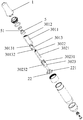
- FIG. 7 is an exploded view of the atomizing assembly shown in FIG.
- the two sets of atomizing core components are specifically a first atomizing core component 301 and a second atomizing core component 302.
- the second atomizing core assembly 302 includes a second oil guiding rope 3021, a second heating wire 3022 wound on the second oil guiding rope 3021, and a hollow cylindrical shape having opposite first ends and second ends.
- the second support tube 3023 includes a second oil guiding rope 3021, a second heating wire 3022 wound on the second oil guiding rope 3021, and a hollow cylindrical shape having opposite first ends and second ends.
- a first pair of recesses 30231 and a second pair of recesses 30232 are disposed on the first end of the second support tube 3023, wherein the positions of each pair of recesses are opposite, and the depth of the second pair of recesses 30232 is greater than the first The depth of the recess 30231; the second end of the second support tube 3023 passes through the oil barrier 22 to press the oil barrier 22 toward the cavity.
- the first end of the second support tube 3023 is an atomization space. After the two sets of atomization core assemblies are assembled, the first electric heating wire and the second electric heating wire are respectively accommodated in the atomization space, and respectively in the atomization space. The atomizing oil on the first oil guiding rope and the second oil guiding rope is atomized.
- the cooperation of the first set of atomizing core components and the second set of atomizing core components is ingenious, so that the space occupied by the two sets of atomizing core components is small, and the volume of the electronic cigarette is avoided.
- the structure of the nozzle assembly has various forms.
- the nozzle assembly 1 is detachably disposed at one end of the oil storage assembly 2.
- the nozzle assembly 1 includes a suction nozzle 11 having a hollow cylindrical shape as a whole, a connecting ring 12, and a connecting seat 13 in an annular shape.
- FIG. 8 is a cross-sectional structural diagram of another embodiment of the atomization assembly of the present invention
- FIG. 9 is an exploded view of the atomization assembly of FIG.
- the diameter of the first end of the atomization seat 34 is smaller than the diameter of the second end, and the first end is provided with two opposite recesses 341, and the first end is an atomization space.
- the oil guiding rope 31 is mounted on the two recesses 341 such that a portion around which the heating wire 32 is wound is accommodated in the atomizing space.
- a vent hole 222 is formed in an intermediate portion of the oil damper 22 in the oil storage assembly 1 excluding the oil passage 221 .
- the side wall of the vent hole 222 extends away from the nozzle assembly 1 such that the oil damper 22 faces the side of the nozzle assembly 1 to form a convex portion.
- the first end of the atomization seat 34 is sleeved outside the convex portion of the oil barrier plate to press the oil barrier plate 22 toward the oil reservoir 211, and clamp the heating wire 32
- the convex portion of the oil barrier 22 and the atomization seat 34 are intermediate.
- a passage 213 connecting the nozzle assembly 1 and the vent hole 222 of the oil damper 22 is further disposed in the oil storage sleeve 21 in the axial direction, so that the smoke generated in the atomization space can pass through the The vent 222 and the passage 213 reach the nozzle assembly 1.
- an annular card 342 is protruded from the inner side wall of the second end of the atomizing seat 34.
- the electrode assembly 4 includes an insulating ring 41 spanned on the annular card 342 and an inner electrode 42 embedded in the middle of the insulating ring 41.
- the nozzle assembly 1 includes a nozzle cover 91 and a seal ring 92 fixed in the nozzle cover 91, wherein the through hole 921 at the center of the seal ring 92 is aligned with the nozzle A passage 213 in the oil storage jacket 21 is described.
- the nozzle assembly 1 is detachably covered at one end of the oil reservoir 21 such that the seal ring 92 seals the opening of the oil reservoir in the oil reservoir 21.
- the user when adding the smoke oil, the user can add the oil to the opening of the nozzle assembly through the oil storage chamber in the oil storage sleeve 21, and seal the oil storage chamber when the nozzle assembly is covered with the oil storage sleeve to avoid leakage. Oil phenomenon.
- the present application also provides an electronic cigarette including an interconnected battery assembly and an atomizing assembly, wherein the battery assembly is not described herein in the prior art.
- the atomizing assembly includes a nozzle assembly, an oil storage assembly, an atomizing core assembly for atomizing smoke oil, and an electrode assembly for electrically connecting with the battery assembly, wherein the nozzle assembly and the electrode assembly Provided at both ends of the oil storage assembly;
- the oil storage assembly includes an oil storage sleeve, and the oil storage jacket is provided with at least two oil storage chambers for storing the oil oil, and one end surface of the oil storage sleeve is formed with a fuel filler port.
- An end surface of the oil reservoir facing the fuel filler port is formed with a cavity, and the cavity cover is provided with a grease barrier that elastically abuts against an inner wall of the oil storage sleeve, and the oil barrier plate corresponds to each of the oil barriers
- An oil hole communicating with the oil storage chamber is disposed at a position of the oil storage chamber;
- the atomizing core assembly is detachably inserted into one end of the oil storage sleeve provided with the fueling port, and the atomizing core assembly comprises an oil guiding rope and an electric heating wire wound around the oil guiding rope.
- the oil guiding rope is inserted into the oil storage chamber through the oil passage hole for transferring the oil in the oil storage chamber to the electric heating wire, and the oil guiding rope and the passing oil
- the inner wall of the oil hole is interference fit.
- the specific structure of the atomizing component of the electronic cigarette can be referred to the specific structure of the atomizing component described above. Since the structure of the atomizing component of the electronic cigarette is the same as that of the atomizing component described above, it also has the same structure. effect.
Abstract
An atomisation assembly and electronic cigarette, the atomisation assembly comprising an atomisation core assembly (3) used for atomising e-liquid, an e-liquid storage assembly (2), and a mouthpiece assembly (1) and electrode assembly (4) respectively arranged at the two ends of the e-liquid storage assembly (2); the e-liquid storage assembly (2) comprises an e-liquid storage sleeve (21) provided with at least two mutually isolated e-liquid storage chambers (211), an e-liquid filling opening (210) being formed on the end face of one end of the e-liquid storage sleeve (21), a chamber opening (2110) being formed on the end face of the e-liquid storage chamber (211) facing the e-liquid filling opening (210), the chamber opening (2110) being covered by an e-liquid separating plate (22) flexibly abutting the inner wall of the e-liquid storage sleeve (21), and e-liquid through-holes (221) corresponding to the position of each e-liquid storage chamber (211) being arranged on the e-liquid separating plate (22) and being in communication with the e-liquid storage chamber (211); the atomisation core assembly (3) is removably inserted in the end of the e-liquid storage sleeve (21) provided with the e-liquid filling opening, the atomisation core assembly (3) comprising an e-liquid guide wick (31) and an electric heating wire (32), the e-liquid guide wick (31) passing through the e-liquid through-holes (221) and entering the e-liquid storage chamber (211), and being used for transferring the e-liquid in the e-liquid storage chamber (211) to the electric heating wire (32) for atomisation, the e-liquid guide wick (31) having an interference fit to the inner walls of the e-liquid through-holes (221). The present atomisation assembly and electronic cigarette can provide the user with a mix of different e-liquid flavours.
Description
本实用新型涉及电子烟技术领域,特别涉及一种雾化组件和电子烟。The utility model relates to the field of electronic cigarette technology, in particular to an atomization assembly and an electronic cigarette.
电子烟是一种新型的电子产品,其与普通的香烟有着相似的外观,以及与香烟相似的味道,但是电子烟相对于传统的香烟更为的健康以及环保。E-cigarettes are a new type of electronic product that has a similar appearance to ordinary cigarettes and a similar taste to cigarettes, but e-cigarettes are healthier and more environmentally friendly than traditional cigarettes.
现有的电子烟中设有雾化器,该雾化器中包括用于存储烟油的储油棉以及用于将该储油棉内的烟油雾化的雾化芯。由于储油棉中仅能存储一种烟油,因此现有的电子烟仅能提供一种口味的烟油,口味较单调,无法提供给用户更多的选择。An atomizer is provided in the existing electronic cigarette, and the atomizer includes an oil storage cotton for storing the oil and an atomizing core for atomizing the oil in the oil storage cotton. Since only one type of smoke oil can be stored in the oil storage cotton, the existing electronic cigarette can only provide one type of smoke oil, and the taste is monotonous, which cannot provide more choices for the user.
实用新型内容Utility model content
本实用新型提供了一种雾化组件和电子烟,能够给用户提供不同烟油的混合口味。The utility model provides an atomization component and an electronic cigarette, which can provide the user with a mixed taste of different smoke oils.
本实用新型提供了一种雾化组件,用于与电池组件组合形成电子烟,其特征在于,所述雾化组件包括吸嘴组件、储油组件、用于雾化烟油的雾化芯组件和用于与所述电池组件电连接的电极组件,其中所述吸嘴组件和所述电极组件分别设置于所述储油组件的两端;The utility model provides an atomization assembly for forming an electronic cigarette in combination with a battery assembly, characterized in that the atomization assembly comprises a nozzle assembly, an oil storage assembly, and an atomization core assembly for atomizing the tobacco oil. And an electrode assembly for electrically connecting to the battery assembly, wherein the nozzle assembly and the electrode assembly are respectively disposed at both ends of the oil storage assembly;
所述储油组件包括储油套,所述储油套内设置有至少两个相互隔离的、用于存储烟油的储油腔,所述储油套的一端端面形成有加油口,所述储油腔的面向所述加油口的端面形成有腔口,所述腔口盖设有与所述储油套的内壁弹性抵接的隔油板,所述隔油板上对应每个所述储油腔的位置处设置有与所述储油腔相连通的过油孔;The oil storage assembly includes an oil storage sleeve, and the oil storage jacket is provided with at least two oil storage chambers for storing the oil oil, and one end surface of the oil storage sleeve is formed with a fuel filler port. An end surface of the oil reservoir facing the fuel filler port is formed with a cavity, and the cavity cover is provided with a grease barrier that elastically abuts against an inner wall of the oil storage sleeve, and the oil barrier plate corresponds to each of the oil barriers An oil hole communicating with the oil storage chamber is disposed at a position of the oil storage chamber;
所述雾化芯组件可拆卸插置于所述储油套的设置有所述加油口的一端内,所述雾化芯组件包括导油绳以及缠绕在所述导油绳上的电热丝,所述导油绳穿过所述过油孔插入所述储油腔内,用于将所述储油腔内的烟油传送至所述电热丝雾化,所述导油绳和所述过油孔的内壁过盈配合。The atomizing core assembly is detachably inserted into one end of the oil storage sleeve provided with the fueling port, and the atomizing core assembly comprises an oil guiding rope and an electric heating wire wound around the oil guiding rope. The oil guiding rope is inserted into the oil storage chamber through the oil passage hole for transferring the oil in the oil storage chamber to the electric heating wire, and the oil guiding rope and the passing oil The inner wall of the oil hole is interference fit.
所述的雾化组件,其中,所述储油套内设置有四个相互隔离的储油腔,且
所述四个储油腔旋转对称设置,所述四个储油腔内分别存储有不同的烟油;The atomizing assembly, wherein the oil storage sleeve is provided with four oil storage chambers isolated from each other, and
The four oil storage chambers are rotationally symmetrically disposed, and different oils are stored in the four oil storage chambers;
所述雾化组件包括一套可拆卸设置的雾化芯组件,所述雾化芯组件的导油绳的两端可选择同时插入其中相对的两个储油腔内,或者同时插入另外相对的两个储油腔内。The atomizing assembly comprises a detachably arranged atomizing core assembly, and two ends of the oil guiding rope of the atomizing core assembly can be simultaneously inserted into two opposite oil reservoirs therein, or simultaneously inserted into another opposite one. Inside the two oil reservoirs.
所述的雾化组件,其中,所述雾化组件包括两套雾化芯组件,所述两套雾化芯组件中的两个导油绳的四端分别插入所述四个储油腔内。The atomizing assembly, wherein the atomizing assembly comprises two sets of atomizing core assemblies, and four ends of two of the two sets of atomizing core assemblies are respectively inserted into the four oil storage chambers .
所述的雾化组件,其中,所述两套雾化芯组件具体为第一雾化芯组件和第二雾化芯组件;The atomizing assembly, wherein the two sets of atomizing core components are specifically a first atomizing core component and a second atomizing core component;
所述第一雾化芯组件包括第一导油绳、缠绕在所述第一导油绳上的第二电热丝和具有相对的第一端和第二端的、呈中空筒状的第一支撑管;The first atomizing core assembly includes a first oil guiding rope, a second heating wire wound on the first oil guiding rope, and a first support having a hollow cylindrical shape having opposite first and second ends tube;
所述第二雾化芯组件包括第二导油绳、缠绕在所述第二导油绳上的第二电热丝和具有相对的第一端和第二端的、呈中空筒状的第二支撑管;The second atomizing core assembly includes a second oil guiding rope, a second heating wire wound on the second oil guiding rope, and a second support having a hollow cylindrical shape having opposite first and second ends tube;
所述第一支撑管的第一端上设置有相对的两个凹部,第二端上设置有相对的两个凹部,且第一端上的两个凹部的连线和第二端上的两个凹部的连线垂直;The first support tube is provided with two opposite recesses on the first end, the opposite ends are provided on the second end, and the two recesses on the first end and the second end on the second end The lines of the recesses are vertical;
所述第二支撑管的第一端上设置有第一对凹部和第二对凹部,其中每一对凹部的位置相对,且所述第二对凹部的深度大于所述第一对凹部的深度;所述第二支撑管的第二端穿过所述隔油板以将所述隔油板压向所述腔口;a first pair of recesses and a second pair of recesses are disposed on the first end of the second support tube, wherein the positions of each pair of recesses are opposite, and the depth of the second pair of recesses is greater than the depth of the first pair of recesses The second end of the second support tube passes through the oil barrier plate to press the oil barrier plate toward the cavity;
所述第一支撑管的第二端嵌入所述第二支撑管的第一端内,并将所述第二导油绳夹在中间,其中,所述第二导油绳同时穿过所述第二支撑管的第一端上的第二对凹部以及所述第一支撑管的第二端上的两个凹部,且两端分别穿过所述过油孔插入相对的两个储油腔内;a second end of the first support tube is embedded in the first end of the second support tube, and the second oil guiding rope is sandwiched therebetween, wherein the second oil guiding rope passes through the same a second pair of recesses on the first end of the second support tube and two recesses on the second end of the first support tube, and the two ends are respectively inserted through the oil passage holes into the opposite two oil storage chambers Inside;
所述第一导油绳同时穿过所述第一支撑管的第一端上的两个凹部以及所述第二支撑管的第一端上的第一对凹部,且两端分别穿过所述过油孔插入另外相对的两个储油腔内。The first oil guiding rope simultaneously passes through two recesses on the first end of the first support tube and a first pair of recesses on the first end of the second support tube, and the two ends respectively pass through the The oil holes are inserted into the other two opposite oil reservoirs.
所述的雾化组件,其中,所述储油套内设有四个沿所述储油套中心轴方向延伸的、呈部分柱面状的侧壁,其中每个侧壁和所述储油套的内壁围成一个所述储油腔,所述储油套内除所述储油腔以外的其余部分为中空的。The atomization assembly, wherein the oil storage sleeve is provided with four side walls which are partially cylindrical in the direction of the central axis of the oil storage sleeve, wherein each side wall and the oil storage The inner wall of the sleeve encloses one of the oil reservoirs, and the remainder of the oil reservoir except the oil reservoir is hollow.
所述的雾化组件,其中,所述储油套内设有以所述储油套的中心轴为轴的
中空圆柱,以及分别连接所述中空圆柱的外侧壁和所述储油套的内侧壁的、沿所述储油套的径向延伸的四个平面,使得任意相邻的两个平面、所述中空圆柱的外侧壁和所述储油套的内侧壁之间形成一个所述储油腔。The atomizing assembly, wherein the oil storage sleeve is provided with an axis of the oil storage sleeve as an axis
a hollow cylinder, and four planes extending along a radial direction of the oil reservoir, respectively, connecting the outer side wall of the hollow cylinder and the inner side wall of the oil reservoir such that any two adjacent planes, An oil reservoir is formed between the outer side wall of the hollow cylinder and the inner side wall of the oil reservoir.
所述的雾化组件,其中,所述雾化芯组件位于所述储油套面向所述吸嘴组件的一端内;The atomizing assembly, wherein the atomizing core assembly is located in an end of the oil reservoir facing the nozzle assembly;
所述雾化组件还包括总体呈中空筒状的、包括相对的第一端和第二端的支撑管;所述支撑管的第一端设有相对的两个凹部,第二端穿过所述隔油板以将所述隔油板压向所述腔口;The atomizing assembly further includes a support tube having a generally hollow end and including opposite first and second ends; the first end of the support tube is provided with two opposite recesses, and the second end passes through the a grease trap to press the grease trap toward the cavity;
所述导油绳包括架设在所述支撑管的第一端的两个凹部上的雾化段,以及位于所述雾化段两端的烟油吸附段,所述两个烟油吸附段分别穿过所述过油孔插入不同的储油腔内。The oil guiding rope comprises an atomizing section which is arranged on two concave portions of the first end of the supporting pipe, and a smoke oil adsorption section which is located at two ends of the atomizing section, and the two smoke oil adsorption sections respectively wear The oil holes are inserted into different oil storage chambers.
所述的雾化组件,其中,所述雾化组件还包括雾化盖;The atomizing assembly, wherein the atomizing assembly further comprises an atomizing cover;
所述雾化盖盖设在所述支撑管的第一端上,以将所述导油绳固定在所述支撑管上,且所述雾化盖上还设有连通所述雾化段和所述吸嘴组件的通孔,使得所述雾化段雾化的烟雾能够通过所述通孔到达所述吸嘴组件。The atomizing cover is disposed on the first end of the support tube to fix the oil guiding rope on the support tube, and the atomizing cover is further provided with the atomization section and The through hole of the nozzle assembly enables the atomized mist to reach the nozzle assembly through the through hole.
所述的雾化组件,其中,所述雾化芯组件位于所述储油套背向所述吸嘴组件的一端内;The atomizing assembly, wherein the atomizing core assembly is located in an end of the oil storage sleeve facing away from the nozzle assembly;
所述雾化芯组件还包括总体呈中空筒状的、包括相对的第一端和第二端的雾化座,所述雾化座的第一端的口径小于第二端的口径;所述雾化座的第一端上设有相对的两个凹部,所述导油绳架设在所述两个凹部上;The atomizing core assembly further includes an atomizing seat having a generally hollow cylindrical shape including opposite first ends and second ends, the first end of the atomizing seat having a smaller diameter than the second end; the atomizing The first end of the seat is provided with two opposite recesses, and the oil guiding rope is arranged on the two recesses;
所述隔油板上除所述过油孔以外的中间区域上设有通气孔,所述通气孔的侧壁朝远离所述吸嘴组件的方向延伸,使得所述隔油板背向所述吸嘴组件的一面上形成凸部;所述雾化座的第一端套设在所述隔油板的凸部外,以将所述隔油板压向所述储油腔,并将所述电热丝夹紧在所述隔油板的凸部和所述雾化座中间;a vent hole is disposed on the oil-repellent plate in an intermediate portion other than the oil-passing hole, and a sidewall of the vent hole extends away from the nozzle assembly such that the oil-repellent plate faces away from the Forming a convex portion on one side of the nozzle assembly; the first end of the atomization seat is sleeved outside the convex portion of the oil barrier plate to press the oil barrier plate toward the oil storage chamber, and The electric heating wire is clamped between the convex portion of the oil barrier plate and the atomization seat;
所述储油套内沿轴向还设有连通所述吸嘴组件和所述隔油板上的通气孔的通道。A passage communicating with the venting opening of the nozzle assembly and the grease damper is also provided in the oil reservoir.
所述的雾化组件,其中,所述吸嘴组件包括吸嘴盖以及固定在所述吸嘴盖内的密封环,其中所述密封环的中心处的通孔对准所述储油套内的通道;
The atomizing assembly, wherein the nozzle assembly includes a nozzle cover and a seal ring fixed in the nozzle cover, wherein a through hole at a center of the seal ring is aligned with the oil reservoir Channel
所述吸嘴组件可拆卸地盖设在所述储油套的一端,使得所述密封环将所述储油套内的储油腔的开口密封。The nozzle assembly is detachably mounted at one end of the oil reservoir such that the seal ring seals an opening of an oil reservoir in the oil reservoir.
所述的雾化组件,其中,所述雾化座的内侧壁上凸设有环形卡台;The atomization assembly, wherein an annular card table is convexly disposed on an inner sidewall of the atomization seat;
所述电极组件包括架设在所述环形卡台上的绝缘环以及嵌在所述绝缘环中间的内电极。The electrode assembly includes an insulating ring erected on the annular card stage and an inner electrode embedded in the middle of the insulating ring.
本实用新型还提供了一种电子烟,包括相互连接的电池组件和雾化组件,其特征在于,所述雾化组件为上述的雾化组件。The present invention also provides an electronic cigarette comprising an interconnected battery assembly and an atomizing assembly, wherein the atomizing assembly is the atomizing assembly described above.
从以上技术方案可以看出,本实用新型具有以下优点:As can be seen from the above technical solutions, the utility model has the following advantages:
本实用新型中,由于储油套内设置有至少两个相互隔离的、用于存储烟油的储油腔,能够方便用户在不同的储油腔中存放不同的烟油,进而能够让用户吸食到不同烟油的混合口味;其次,由于各储油腔全设置在储油套内,导油绳通过隔油板上对应各储油腔的过油孔来插入各储油腔内,使得电子烟在存放多种烟油的同时保持结构简单,且由于所述隔油板与所述储油套的内壁弹性抵接,所述导油绳与所述过油孔的内壁过盈配合,因而能够较好地密封各储油腔中烟油,且使每个所述储油腔中的烟油均匀地输送给所述电热丝进行雾化,保证了烟雾口味的一致性;最后,由于所述雾化芯组件可拆卸插置于所述储油套的设置有所述加油口的一端内,因而不仅便于更换雾化芯及更换不同口味的烟油,而且使本实用新型的整体结构较为简单紧凑。In the utility model, since the oil storage sleeve is provided with at least two oil storage chambers for storing the smoke oil, the user can conveniently store different oils in different oil storage chambers, thereby allowing the user to smoke. To the mixed taste of different smoke oils; secondly, since the oil storage chambers are all disposed in the oil storage jacket, the oil guiding ropes are inserted into the oil storage chambers through the oil passage holes corresponding to the respective oil storage chambers on the oil barrier plate, so that the electrons are inserted into the oil storage chambers The cigarette keeps the structure while storing a plurality of smoke oils, and since the oil barrier plate elastically abuts against the inner wall of the oil storage jacket, the oil guiding rope is interference-fitted with the inner wall of the oil passage hole, thereby The smoke oil in each oil storage chamber can be better sealed, and the smoke oil in each of the oil storage chambers can be evenly transported to the electric heating wire for atomization, thereby ensuring the consistency of the smoke taste; finally, due to The atomizing core assembly is detachably inserted into one end of the oil storage sleeve provided with the fueling opening, thereby not only facilitating replacement of the atomizing core and replacement of different flavors of smoke oil, but also making the overall structure of the utility model relatively Simple and compact.
图1为本实用新型中雾化组件的一个实施例的剖面结构示意图;1 is a schematic cross-sectional structural view of an embodiment of an atomizing assembly of the present invention;
图2为图1所示雾化组件的爆炸图;Figure 2 is an exploded view of the atomizing assembly of Figure 1;
图3为图1所示雾化组件内的储油套的结构示意图;3 is a schematic structural view of an oil storage jacket in the atomizing assembly shown in FIG. 1;
图4为本实用新型的雾化组件中储油套的一种实施例的结构示意图;4 is a schematic structural view of an embodiment of an oil storage sleeve in the atomization assembly of the present invention;
图5为本实用新型的雾化组件中储油套的另一种实施例的结构示意图;5 is a schematic structural view of another embodiment of an oil storage sleeve in the atomization assembly of the present invention;
图6为本实用新型的雾化组件的又一个实施例的剖面结构示意图;Figure 6 is a cross-sectional structural view showing still another embodiment of the atomizing assembly of the present invention;
图7为图6所示雾化组件的爆炸图;Figure 7 is an exploded view of the atomizing assembly shown in Figure 6;
图8为本实用新型的雾化组件的另一种实施例的剖面结构示意图;Figure 8 is a cross-sectional structural view showing another embodiment of the atomizing assembly of the present invention;
图9为图8所示雾化组件的爆炸图。
Figure 9 is an exploded view of the atomizing assembly of Figure 8.
本实用新型公开了一种雾化组件和电子烟,给用户提供不同烟油的混合口味。The utility model discloses an atomizing component and an electronic cigarette, which provide the user with a mixed taste of different smoke oils.
下面将结合本实用新型实施例中的附图,对本实用新型实施例中的技术方案进行清楚、完整地描述,显然,所描述的实施例仅仅是本实用新型一部分实施例,而不是全部的实施例。基于本实用新型中的实施例,本领域普通技术人员在没有做出创造性劳动前提下所获得的所有其他实施例,都属于本实用新型保护的范围。The technical solutions in the embodiments of the present invention will be clearly and completely described in conjunction with the drawings in the embodiments of the present invention. It is obvious that the described embodiments are only a part of the embodiments of the present invention, and not all of the embodiments. example. All other embodiments obtained by those skilled in the art based on the embodiments of the present invention without creative efforts are within the scope of the present invention.
请参阅图1和图2,图1为本实用新型中雾化组件的一个实施例的剖面结构示意图,图2为图1所示雾化组件的爆炸图。图1所示的雾化组件用于与电池组件(图未示)组合形成电子烟。Please refer to FIG. 1 and FIG. 2. FIG. 1 is a cross-sectional structural view of an embodiment of the atomizing assembly of the present invention, and FIG. 2 is an exploded view of the atomizing assembly of FIG. The atomizing assembly shown in Figure 1 is used in combination with a battery pack (not shown) to form an electronic cigarette.
如图1所示,雾化组件包括吸嘴组件1、储油组件2、用于雾化烟油的雾化芯组件3和用于与所述电池组件电连接的电极组件4,其中所述吸嘴组件1和所述电极组件4分别设置于所述储油组件2的两端,所述雾化芯组件3位于所述储油组件2的一端内。As shown in FIG. 1, the atomizing assembly includes a nozzle assembly 1, an oil storage assembly 2, an atomizing core assembly 3 for atomizing smoke oil, and an electrode assembly 4 for electrically connecting with the battery assembly, wherein The nozzle assembly 1 and the electrode assembly 4 are respectively disposed at both ends of the oil storage assembly 2, and the atomization core assembly 3 is located at one end of the oil storage assembly 2.
具体的,本实施例中,储油组件2包括储油套21。所述储油套21内设置有至少两个相互隔离的储油腔211,其中,不同的储油腔211沿所述储油套的周向分布,且不同的储油腔211用于存储不同的烟油。具体的,本实施例中,储油套21内设置有两个储油腔211。优选的,储油套21由透明材料制成,以方便用户查看储油腔内的烟油量。Specifically, in the embodiment, the oil storage assembly 2 includes an oil storage jacket 21. The oil storage jacket 21 is provided with at least two mutually isolated oil storage chambers 211, wherein different oil storage chambers 211 are distributed along the circumferential direction of the oil storage jacket, and different oil storage chambers 211 are used for storing different Smoke oil. Specifically, in the embodiment, two oil storage chambers 211 are disposed in the oil storage jacket 21. Preferably, the oil storage jacket 21 is made of a transparent material to facilitate the user to view the amount of smoke oil in the oil storage chamber.
所述储油套21的一端的端面形成有加油口210,且所述储油套21内的各储油腔211的面向所述加油口210的端面形成有腔口2110。需注意的是,各储油腔211的腔口2110可以和加油口210位于同一平面上,也可以位于储油套21内。An oil supply port 210 is formed on an end surface of one end of the oil storage jacket 21 , and a cavity 2110 is formed on an end surface of each oil storage chamber 211 in the oil storage jacket 21 facing the fuel filler port 210 . It should be noted that the cavity 2110 of each oil storage chamber 211 may be located on the same plane as the fuel filler 210 or may be located in the oil storage jacket 21.
各储油腔211的腔口2110上还盖设有与所述储油套21的内壁弹性抵接的隔油板22。优选的,隔油板22为硅胶材质,以能够密封烟油。隔油板22上对应每个储油腔211的位置处设置有与该储油腔211相连通的过油孔221。The oil reservoir 22 of the oil reservoir 211 is further covered with a grease barrier 22 that elastically abuts against the inner wall of the oil reservoir 21. Preferably, the oil barrier 22 is made of a silicone material to seal the smoke oil. An oil passage 221 communicating with the oil reservoir 211 is disposed at a position corresponding to each of the oil reservoirs 211 on the oil barrier 22 .
雾化芯组件3包括导油绳31以及缠绕在所述导油绳31上的电热丝32。所述雾化芯组件3可拆卸设置于储油套21的设置有加油口210的一端内。在
本实施例中,所述雾化芯组件3通过涨紧配合的方式可拆卸设置于储油套21的一端内,当然,也可以通过螺纹或磁吸等方式,在此不作具体限定。所述导油绳31的两端分别穿过不同的过油孔221插入到不同的储油腔211内,用于将两个储油腔211内的不同烟油同时传送至电热丝32进行雾化,以产生由至少两种不同烟油混合的口味的烟雾。The atomizing core assembly 3 includes an oil guiding rope 31 and a heating wire 32 wound around the oil guiding rope 31. The atomizing core assembly 3 is detachably disposed in one end of the oil reservoir 21 provided with the fuel filler port 210. In
In this embodiment, the atomizing core assembly 3 is detachably disposed in one end of the oil storage jacket 21 by means of a tightening fit. Of course, it may be threaded or magnetically attracted, and is not specifically limited herein. The two ends of the oil guiding rope 31 are respectively inserted into different oil storage chambers 211 through different oil passage holes 221 for simultaneously transmitting different oils in the two oil storage chambers 211 to the heating wire 32 for fogging. To produce a smoke that is mixed by at least two different types of smoke oil.
所述导油绳31还与所述过油孔221的内壁过盈配合,以避免储油腔211内的烟油从导油绳31和过油孔221之间的缝隙渗出,造成漏油现象。The oil guiding rope 31 also has an interference fit with the inner wall of the oil passage hole 221 to prevent the oil in the oil storage chamber 211 from oozing out from the gap between the oil guiding rope 31 and the oil passing hole 221, thereby causing oil leakage. phenomenon.
本实施例中,由于储油套内设置有至少两个相互隔离的、用于存储烟油的储油腔,能够方便用户在不同的储油腔中存放不同的烟油,进而能够让用户吸食到不同烟油的混合口味;而且,各储油腔全设置在储油套内,导油绳通过隔油板上对应各储油腔的过油孔来插入各储油腔内,使得电子烟在存放多种烟油的同时保持结构简单。In this embodiment, since the oil storage jacket is provided with at least two mutually isolated oil storage chambers for storing the oil, the user can conveniently store different oils in different oil storage chambers, thereby allowing the user to smoke. To the mixed taste of different smoke oils; moreover, each oil storage chamber is completely disposed in the oil storage sleeve, and the oil guiding rope is inserted into each oil storage chamber through the oil passage holes corresponding to the respective oil storage chambers on the oil separation plate, so that the electronic cigarette Keep a simple structure while storing a variety of smoke oils.
本实施例中,雾化芯组件的结构有多种形式,下面结合图1和图2对其中的一种进行具体描述。本实施例中,雾化芯组件3具体位于储油套21面向吸嘴组件1的一端内。In this embodiment, the structure of the atomizing core assembly has various forms, and one of them will be specifically described below with reference to FIGS. 1 and 2. In this embodiment, the atomizing core assembly 3 is specifically located in an end of the oil reservoir 21 facing the nozzle assembly 1.
雾化芯组件3还包括总体呈中空筒状的、包括相对的第一端和第二端的支撑管33。具体的,所述支撑管33的第一端的口径大于第二端的口径,使得支撑管33的外侧壁上第一端和第二端之间形成有环形台阶331。支撑管33的第一端设有相对的两个凹部332,且该第一端的中空处为雾化空间。支撑管33的第二端穿过隔油板22,支撑管33的环形台阶331抵持在隔油板22上,以将隔油板22压向储油腔211的腔口2110。The atomizing core assembly 3 also includes a support tube 33 that is generally hollow cylindrical and includes opposing first and second ends. Specifically, the diameter of the first end of the support tube 33 is larger than the diameter of the second end, so that an annular step 331 is formed between the first end and the second end of the outer side wall of the support tube 33. The first end of the support tube 33 is provided with two opposite recesses 332, and the hollow portion of the first end is an atomization space. The second end of the support tube 33 passes through the oil barrier 22, and the annular step 331 of the support tube 33 abuts against the oil barrier 22 to press the oil barrier 22 against the cavity 2110 of the oil reservoir 211.
雾化芯组件5中的导油绳31包括雾化段311以及分别位于所述雾化段两端的两个烟油吸附段312。所述雾化段311架设在支撑管33的两个凹部332上,以容置在雾化空间内对烟油进行雾化。所述两个烟油吸附段312分别穿过两个过油孔221插入不同的储油腔211内。The oil guiding rope 31 in the atomizing core assembly 5 includes an atomizing section 311 and two smoke adsorbing sections 312 respectively located at both ends of the atomizing section. The atomization section 311 is mounted on the two recesses 332 of the support tube 33 to accommodate the atomization of the smoke oil in the atomization space. The two soot adsorption sections 312 are respectively inserted into the different oil reservoirs 211 through the two oil passages 221 .
当然,本实施例中,支撑管33的第一端的口径也可以不是大于第二端的口径,在此不作限制。Of course, in this embodiment, the diameter of the first end of the support tube 33 may not be larger than the diameter of the second end, which is not limited herein.
优选的,本实施例中,雾化组件还包括雾化盖5,所述雾化盖5盖设在所述支撑管33的第一端上,以将架设在支撑管33的第一端上的所述导油绳31
固定在所述支撑管33上。雾化盖5背向支撑管33的一端和吸嘴组件1相抵持,且所述雾化盖5上还设有连通所述雾化空间和所述吸嘴组件1的通孔51,使得所述雾化空间内的雾化段311雾化的烟雾能够通过所述通孔51到达所述吸嘴组件1。Preferably, in this embodiment, the atomization assembly further includes an atomization cover 5, and the atomization cover 5 is disposed on the first end of the support tube 33 to be mounted on the first end of the support tube 33. The oil guiding rope 31
It is fixed to the support tube 33. One end of the atomizing cover 5 facing away from the supporting tube 33 and the nozzle assembly 1 are abutted, and the atomizing cover 5 is further provided with a through hole 51 communicating with the atomizing space and the nozzle assembly 1 so that The mist atomized by the atomization section 311 in the atomization space can reach the nozzle assembly 1 through the through hole 51.
本实施例中,储油套内的储油腔的结构有多种形式。例如,请参阅图3,图3为图1所示雾化组件内的储油套的结构示意图。本实施例中,储油套21内设有两个沿储油套21的中心轴方向延伸的侧壁212,其中该两个侧壁212均呈部分柱面状,且每个侧壁212和储油套21的内壁围成一个储油腔211。In this embodiment, the structure of the oil reservoir in the oil reservoir has various forms. For example, please refer to FIG. 3. FIG. 3 is a schematic structural view of an oil storage sleeve in the atomizing assembly shown in FIG. In this embodiment, the oil storage jacket 21 is provided with two side walls 212 extending along the central axis direction of the oil storage jacket 21, wherein the two side walls 212 are partially cylindrical, and each side wall 212 and The inner wall of the oil storage jacket 21 encloses an oil reservoir 211.
优选的,本实施例中,储油套21内设置有四个相互隔离的储油腔211。如图4所示,图4为本实用新型的雾化组件中储油套的一种实施例的结构示意图。本实施例中,储油套21内的四个储油腔以所述储油套21的中心轴为轴旋转对称设置,且该四个储油腔内分别存储有不同的烟油。Preferably, in the embodiment, four oil storage chambers 211 are disposed in the oil storage jacket 21 . As shown in FIG. 4, FIG. 4 is a schematic structural view of an embodiment of an oil storage sleeve in the atomization assembly of the present invention. In this embodiment, the four oil storage chambers in the oil storage jacket 21 are rotationally symmetrically disposed with the central axis of the oil storage jacket 21 as an axis, and different oils are stored in the four oil storage chambers.
具体的,所述储油套21内设有四个沿所述储油套21中心轴方向延伸的、呈部分柱面状的侧壁212,其中每个侧壁212和所述储油套21的内壁围成一个所述储油腔211,所述储油套21内除所述储油腔211以外的其余部分为中空的。Specifically, the oil storage jacket 21 is provided with four side walls 212 extending in the central axis direction of the oil storage jacket 21, and each of the side walls 212 and the oil storage jacket 21 The inner wall encloses one of the oil storage chambers 211, and the remaining portion of the oil storage jacket 21 except the oil storage chamber 211 is hollow.
实际运用中,储油套21内的储油腔211的侧壁也可以呈腔体形状。例如,如图5所示,图5为本实用新型的雾化组件中储油套的另一种实施例的结构示意图。本实施例中,所述储油套21内设有以所述储油套21的中心轴为轴的中空圆柱214,以及分别连接所述中空圆柱214的外侧壁和所述储油套的内侧壁的、沿所述储油套的径向延伸的四个平面215,使得任意相邻的两个平面215、所述中空圆柱214的外侧壁和所述储油套21的内侧壁之间形成一个所述储油腔211。相比图4所示储油套,本实施例中的储油套更易开模加工。In actual use, the side wall of the oil reservoir 211 in the oil storage jacket 21 may also have a cavity shape. For example, as shown in FIG. 5, FIG. 5 is a schematic structural view of another embodiment of an oil storage sleeve in the atomization assembly of the present invention. In this embodiment, the oil storage sleeve 21 is provided with a hollow cylinder 214 with the central axis of the oil storage sleeve 21 as an axis, and an outer side wall connecting the hollow cylinder 214 and the inner side of the oil storage sleeve, respectively. Four planes 215 of the wall extending along the radial direction of the oil reservoir such that any two adjacent planes 215, the outer sidewalls of the hollow cylinder 214, and the inner sidewall of the oil reservoir 21 are formed One of the oil reservoirs 211. Compared with the oil storage sleeve shown in Fig. 4, the oil storage sleeve in this embodiment is easier to mold.
雾化组件内的雾化芯组件3的数量为一套,由于该雾化芯组件3为可拆卸设置于储油套21的一端内,在将该雾化芯组件3设置到储油套21的一端内时,该雾化芯组件3的导油绳31的两端可选择同时插入其中相对的两个储油腔211内,或者同时插入另外相对的两个储油腔211内。The number of the atomizing core assemblies 3 in the atomizing assembly is one set. Since the atomizing core assembly 3 is detachably disposed in one end of the oil storage jacket 21, the atomizing core assembly 3 is disposed to the oil storage jacket 21 The two ends of the oil guiding cord 31 of the atomizing core assembly 3 can be simultaneously inserted into the two opposite oil reservoirs 211 or simultaneously inserted into the other two opposite oil reservoirs 211.
这样,用户可在不同的电子烟口味中进行选择,能够提高电子烟的用户使用体验。
In this way, the user can select among different e-cigarette flavors, which can improve the user experience of the e-cigarette.
优选的,本实施例中,储油套内除所述储油腔以外的其余部分为中空的。隔油板上对应该储油套的中空部分设有通孔,支撑管的第二端插入该隔油板的通孔内,且支撑管为中空的,使得该支撑管的中空部分、隔油板的通孔和储油套的中空部分一起连通为雾化通道。Preferably, in this embodiment, the remaining portion of the oil storage jacket except the oil storage chamber is hollow. a through hole is formed in the hollow portion of the oil separator corresponding to the oil storage sleeve, the second end of the support tube is inserted into the through hole of the oil barrier plate, and the support tube is hollow, so that the hollow portion of the support tube and the oil separation The through hole of the plate and the hollow portion of the oil reservoir are connected together as an atomizing passage.
本实施例中,雾化组件内也可以不仅仅设有一套雾化芯组件3,而是设置有两套雾化芯组件3,其中每套雾化芯组件3中包括导油绳31以及缠绕在所述导油绳31上的电热丝32。所述两套雾化芯组3件中的两个导油绳31的四端分别插入所述四个储油腔内。In this embodiment, the atomizing core assembly 3 may be provided not only in the atomizing core assembly 3 but also in two sets of atomizing core assemblies 3, wherein each of the atomizing core assemblies 3 includes an oil guiding rope 31 and winding A heating wire 32 on the oil guiding rope 31. The four ends of the two oil guiding ropes 31 of the two sets of atomizing core groups 3 are respectively inserted into the four oil storage chambers.
具体的,一套雾化芯组件3中的导油绳31的两端分别插入储油套21内其中相对的两个储油腔211内,另一套雾化芯组件3中的导油绳31的两端分别插入储油套21内另外相对的两个储油腔211内。Specifically, two ends of the oil guiding rope 31 in the atomizing core assembly 3 are respectively inserted into the opposite oil reservoirs 211 in the oil storage jacket 21, and the oil guiding ropes in the other atomizing core assembly 3 are respectively inserted. The two ends of the 31 are respectively inserted into the two opposite oil reservoirs 211 in the oil storage jacket 21.
下面结合图6和图7对该两套雾化芯组件的一种具体结构进行描述。请参阅图6和图7,图6为本实用新型的雾化组件的又一个实施例的剖面结构示意图,图7为图6所示雾化组件的爆炸图。本实施例中,所述两套雾化芯组件具体为第一雾化芯组件301和第二雾化芯组件302。A specific structure of the two sets of atomizing core assemblies will be described below with reference to FIGS. 6 and 7. Please refer to FIG. 6 and FIG. 7. FIG. 6 is a cross-sectional structural view of still another embodiment of the atomizing assembly of the present invention, and FIG. 7 is an exploded view of the atomizing assembly shown in FIG. In this embodiment, the two sets of atomizing core components are specifically a first atomizing core component 301 and a second atomizing core component 302.
所述第一雾化芯组件301包括第一导油绳3011、缠绕在所述第一导油绳301上的第一电热丝3012和具有相对的第一端和第二端的、呈中空筒状的第一支撑管3013。The first atomizing core assembly 301 includes a first oil guiding rope 3011, a first heating wire 3012 wound on the first oil guiding rope 301, and a hollow cylindrical shape having opposite first ends and second ends. The first support tube 3013.
所述第二雾化芯组件302包括第二导油绳3021、缠绕在所述第二导油绳3021上的第二电热丝3022和具有相对的第一端和第二端的、呈中空筒状的第二支撑管3023。The second atomizing core assembly 302 includes a second oil guiding rope 3021, a second heating wire 3022 wound on the second oil guiding rope 3021, and a hollow cylindrical shape having opposite first ends and second ends. The second support tube 3023.
所述第一支撑管3013的第一端上设置有相对的两个凹部30131,第二端上设置有相对的两个凹部30132,且第一端上的两个凹部30131的连线和第二端上的两个凹部30132的连线垂直。The first support tube 3013 is provided with two opposite recesses 30131 on the first end, and two opposite recesses 30132 are disposed on the second end, and the two recesses 30131 on the first end are connected and second. The lines of the two recesses 30132 on the ends are perpendicular.
所述第二支撑管3023的第一端上设置有第一对凹部30231和第二对凹部30232,其中每一对凹部的位置相对,且所述第二对凹部30232的深度大于所述第一对凹部30231的深度;所述第二支撑管3023的第二端穿过所述隔油板22以将所述隔油板22压向所述腔口。a first pair of recesses 30231 and a second pair of recesses 30232 are disposed on the first end of the second support tube 3023, wherein the positions of each pair of recesses are opposite, and the depth of the second pair of recesses 30232 is greater than the first The depth of the recess 30231; the second end of the second support tube 3023 passes through the oil barrier 22 to press the oil barrier 22 toward the cavity.
所述第一支撑管3013的第二端嵌入所述第二支撑管3023的第一端内,并
将所述第二导油绳3021夹在中间,其中,所述第二导油绳3021同时穿过所述第二支撑管3023的第一端上的第二对凹部30232以及所述第一支撑管3013的第二端上的两个凹部30132,且两端分别穿过所述过油孔221插入相对的两个储油腔内211内。The second end of the first support tube 3013 is embedded in the first end of the second support tube 3023, and
The second oil guiding rope 3021 is sandwiched, wherein the second oil guiding rope 3021 simultaneously passes through the second pair of concave portions 30232 on the first end of the second supporting tube 3023 and the first support Two recesses 30132 on the second end of the tube 3013 are inserted into the opposite two oil reservoirs 211 through the oil passages 221, respectively.
所述第一导油绳3011同时穿过所述第一支撑管3013的第一端上的两个凹部30131以及所述第二支撑管3023的第一端上的第一对凹部30231,且两端分别穿过所述过油孔221插入另外相对的两个储油腔211内。The first oil guiding rope 3011 simultaneously passes through two recesses 30131 on the first end of the first support tube 3013 and a first pair of recesses 30231 on the first end of the second support tube 3023, and two The ends are inserted through the oil passage holes 221 into the other two opposite oil reservoirs 211, respectively.
所述第二支撑管3023的第一端内为雾化空间,两套雾化芯组件组装后第一电热丝和第二电热丝均容纳于雾化空间内,并在该雾化空间内分别对第一导油绳和第二导油绳上的烟油进行雾化。The first end of the second support tube 3023 is an atomization space. After the two sets of atomization core assemblies are assembled, the first electric heating wire and the second electric heating wire are respectively accommodated in the atomization space, and respectively in the atomization space. The atomizing oil on the first oil guiding rope and the second oil guiding rope is atomized.
本实施例中,第一套雾化芯组件和第二套雾化芯组件的配合巧妙,使得该两套雾化芯组件所占空间较小,避免增大电子烟的体积。In this embodiment, the cooperation of the first set of atomizing core components and the second set of atomizing core components is ingenious, so that the space occupied by the two sets of atomizing core components is small, and the volume of the electronic cigarette is avoided.
优选的,本实施例中,雾化组件还包括雾化盖5,所述雾化盖5盖设在所述第一支撑管3013的第一端上。雾化盖5背向第一支撑管3013的一端和吸嘴组件1相抵持,且所述雾化盖5上还设有连通所述雾化空间和所述吸嘴组件1的通孔51,使得在所述雾化空间内雾化的烟雾能够通过所述通孔51到达所述吸嘴组件1。Preferably, in this embodiment, the atomization assembly further includes an atomization cover 5, and the atomization cover 5 is disposed on the first end of the first support tube 3013. One end of the atomizing cover 5 facing away from the first supporting tube 3013 and the nozzle assembly 1 are abutted, and the atomizing cover 5 is further provided with a through hole 51 communicating with the atomizing space and the nozzle assembly 1 . The mist atomized in the atomization space can be made to reach the nozzle assembly 1 through the through hole 51.
本实用新型中,吸嘴组件的结构有多种形式。下面结合图1和图2对其中的一种具体结构进行描述。优选的,本实施例中,吸嘴组件1可拆卸设置于储油组件2的一端。具体的,吸嘴组件1包括总体呈中空筒状的吸嘴11、连接环12以及呈环状的连接座13。In the present invention, the structure of the nozzle assembly has various forms. One of the specific structures will be described below with reference to FIGS. 1 and 2. Preferably, in this embodiment, the nozzle assembly 1 is detachably disposed at one end of the oil storage assembly 2. Specifically, the nozzle assembly 1 includes a suction nozzle 11 having a hollow cylindrical shape as a whole, a connecting ring 12, and a connecting seat 13 in an annular shape.
所述连接环12的一端套设在储油套21的一端外,连接环12的另一端上还设有第一螺纹。连接座13的一端上设有与第一螺纹匹配的第二螺纹。连接座13和连接环12通过该第二螺纹和第一螺纹的配合可拆卸连接。One end of the connecting ring 12 is sleeved outside one end of the oil storage sleeve 21, and the other end of the connecting ring 12 is further provided with a first thread. A second thread that matches the first thread is provided on one end of the connector block 13. The connecting seat 13 and the connecting ring 12 are detachably connected by the cooperation of the second thread and the first thread.
吸嘴11靠近所述储油套21的一端插接在连接座13的另一端内,并和储油套21内的雾化芯组件3相抵接。且吸嘴11的中空处通过连接座13的内部和雾化空间相连通,以使得雾化空间内的烟雾能传送到吸嘴11的中空处,供用户吸食。One end of the suction nozzle 11 near the oil storage jacket 21 is inserted into the other end of the connecting seat 13 and abuts against the atomizing core assembly 3 in the oil storage jacket 21. And the hollow portion of the suction nozzle 11 communicates with the atomization space through the inside of the connection seat 13 so that the smoke in the atomization space can be transmitted to the hollow portion of the suction nozzle 11 for the user to suck.
本实用新型中,电极组件的结构有多种形式。下面结合图1和图2对其中
的一种具体结构进行描述。本实施例中,电极组件4设于储油套21背向吸嘴组件1的一端。具体的,电极组件4包括固定在储油套21一端的连接套41。所述连接套41的内侧壁上设有环形卡台411。电极组件4还包括嵌设在所述环形卡台411上的绝缘环42以及嵌设在所述绝缘环42内的内电极43。所述电热丝32的两端穿过所述储油套21的中空处分别和所述内电极43以及所述连接套41电连接。In the present invention, the structure of the electrode assembly has various forms. The following is combined with FIG. 1 and FIG.
A specific structure is described. In this embodiment, the electrode assembly 4 is disposed at one end of the oil reservoir 21 facing away from the nozzle assembly 1. Specifically, the electrode assembly 4 includes a coupling sleeve 41 fixed to one end of the oil storage jacket 21. An annular card table 411 is disposed on an inner sidewall of the connecting sleeve 41. The electrode assembly 4 further includes an insulating ring 42 embedded in the annular card stage 411 and an inner electrode 43 embedded in the insulating ring 42. Both ends of the heating wire 32 are electrically connected to the inner electrode 43 and the connecting sleeve 41 through the hollow portion of the oil storage jacket 21, respectively.
上面所描述的实施例中,雾化芯组件位于储油套21面向吸嘴组件1的一端内。本实用新型中,雾化芯组件也可以不是位于储油套21面向吸嘴组件1的一端内,而是位于储油套21背向吸嘴组件1的一端内。In the embodiment described above, the atomizing core assembly is located in one end of the oil reservoir 21 facing the nozzle assembly 1. In the present invention, the atomizing core assembly may not be located in one end of the oil storage casing 21 facing the nozzle assembly 1, but in an end of the oil storage casing 21 facing away from the nozzle assembly 1.
请参阅图8和图9,图8为本实用新型的雾化组件的另一种实施例的剖面结构示意图,图9为图8所示雾化组件的爆炸图。Please refer to FIG. 8 and FIG. 9. FIG. 8 is a cross-sectional structural diagram of another embodiment of the atomization assembly of the present invention, and FIG. 9 is an exploded view of the atomization assembly of FIG.
与图1所示实施例不同的是,本实施例中,雾化芯组件3不包括支撑管,而是包括总体呈中空筒状的、包括相对的第一端和第二端的雾化座34。该雾化座34的第一端与储油组件1相接,第二端与电极组件4相接。Different from the embodiment shown in FIG. 1, in the present embodiment, the atomizing core assembly 3 does not include a support tube, but includes an atomizing seat 34 including a first hollow end and a second end including a first end and a second end. . The first end of the atomizing seat 34 is in contact with the oil storage assembly 1, and the second end is in contact with the electrode assembly 4.
具体的,所述雾化座34的第一端的口径小于所述第二端的口径,且第一端上设有相对的两个凹部341,所述第一端内为雾化空间,所述导油绳31架设在所述两个凹部341上,以使得缠绕有电热丝32的部分容纳在雾化空间内。Specifically, the diameter of the first end of the atomization seat 34 is smaller than the diameter of the second end, and the first end is provided with two opposite recesses 341, and the first end is an atomization space. The oil guiding rope 31 is mounted on the two recesses 341 such that a portion around which the heating wire 32 is wound is accommodated in the atomizing space.
所述储油组件1中的隔油板22上除所述过油孔221以外的中间区域上设有通气孔222。所述通气孔222的侧壁朝远离所述吸嘴组件1的方向延伸,使得所述隔油板22背向所述吸嘴组件1的一面上形成凸部。A vent hole 222 is formed in an intermediate portion of the oil damper 22 in the oil storage assembly 1 excluding the oil passage 221 . The side wall of the vent hole 222 extends away from the nozzle assembly 1 such that the oil damper 22 faces the side of the nozzle assembly 1 to form a convex portion.
所述雾化座34的第一端套设在所述隔油板的凸部外,以将所述隔油板22压向所述储油腔211,并将所述电热丝32夹紧在所述隔油板22的凸部和所述雾化座34中间。The first end of the atomization seat 34 is sleeved outside the convex portion of the oil barrier plate to press the oil barrier plate 22 toward the oil reservoir 211, and clamp the heating wire 32 The convex portion of the oil barrier 22 and the atomization seat 34 are intermediate.
所述储油套21内沿轴向还设有连通所述吸嘴组件1和所述隔油板22上的通气孔222的通道213,以使得雾化空间内产生的烟雾能依次通过所述通气孔222和通道213到达吸嘴组件1。A passage 213 connecting the nozzle assembly 1 and the vent hole 222 of the oil damper 22 is further disposed in the oil storage sleeve 21 in the axial direction, so that the smoke generated in the atomization space can pass through the The vent 222 and the passage 213 reach the nozzle assembly 1.
优选的,所述雾化座34的第二端内侧壁上凸设有环形卡台342。所述电极组件4包括架设在所述环形卡台342上的绝缘环41以及嵌在所述绝缘环41中间的内电极42。
Preferably, an annular card 342 is protruded from the inner side wall of the second end of the atomizing seat 34. The electrode assembly 4 includes an insulating ring 41 spanned on the annular card 342 and an inner electrode 42 embedded in the middle of the insulating ring 41.
优选的,本实施例中,所述吸嘴组件1包括吸嘴盖91以及固定在所述吸嘴盖91内的密封环92,其中所述密封环92的中心处的通孔921对准所述储油套21内的通道213。所述吸嘴组件1可拆卸地盖设在所述储油套21的一端,使得所述密封环92将所述储油套21内的储油腔的开口密封。Preferably, in the present embodiment, the nozzle assembly 1 includes a nozzle cover 91 and a seal ring 92 fixed in the nozzle cover 91, wherein the through hole 921 at the center of the seal ring 92 is aligned with the nozzle A passage 213 in the oil storage jacket 21 is described. The nozzle assembly 1 is detachably covered at one end of the oil reservoir 21 such that the seal ring 92 seals the opening of the oil reservoir in the oil reservoir 21.
这样,用户在添加烟油时可通过储油套21内的储油腔面向吸嘴组件的开口添加烟油,并在将吸嘴组件盖上储油套时将储油腔密封好,避免漏油现象。In this way, when adding the smoke oil, the user can add the oil to the opening of the nozzle assembly through the oil storage chamber in the oil storage sleeve 21, and seal the oil storage chamber when the nozzle assembly is covered with the oil storage sleeve to avoid leakage. Oil phenomenon.
本申请还提供一种电子烟,该电子烟包括相互连接的电池组件和雾化组件,其中,所述电池组件为现有技术在此不再赘述。所述雾化组件包括吸嘴组件、储油组件、用于雾化烟油的雾化芯组件和用于与所述电池组件电连接的电极组件,其中所述吸嘴组件和所述电极组件分别设置于所述储油组件的两端;The present application also provides an electronic cigarette including an interconnected battery assembly and an atomizing assembly, wherein the battery assembly is not described herein in the prior art. The atomizing assembly includes a nozzle assembly, an oil storage assembly, an atomizing core assembly for atomizing smoke oil, and an electrode assembly for electrically connecting with the battery assembly, wherein the nozzle assembly and the electrode assembly Provided at both ends of the oil storage assembly;
所述储油组件包括储油套,所述储油套内设置有至少两个相互隔离的、用于存储烟油的储油腔,所述储油套的一端端面形成有加油口,所述储油腔的面向所述加油口的端面形成有腔口,所述腔口盖设有与所述储油套的内壁弹性抵接的隔油板,所述隔油板上对应每个所述储油腔的位置处设置有与所述储油腔相连通的过油孔;The oil storage assembly includes an oil storage sleeve, and the oil storage jacket is provided with at least two oil storage chambers for storing the oil oil, and one end surface of the oil storage sleeve is formed with a fuel filler port. An end surface of the oil reservoir facing the fuel filler port is formed with a cavity, and the cavity cover is provided with a grease barrier that elastically abuts against an inner wall of the oil storage sleeve, and the oil barrier plate corresponds to each of the oil barriers An oil hole communicating with the oil storage chamber is disposed at a position of the oil storage chamber;
所述雾化芯组件可拆卸插置于所述储油套的设置有所述加油口的一端内,所述雾化芯组件包括导油绳以及缠绕在所述导油绳上的电热丝,所述导油绳穿过所述过油孔插入所述储油腔内,用于将所述储油腔内的烟油传送至所述电热丝雾化,所述导油绳和所述过油孔的内壁过盈配合。The atomizing core assembly is detachably inserted into one end of the oil storage sleeve provided with the fueling port, and the atomizing core assembly comprises an oil guiding rope and an electric heating wire wound around the oil guiding rope. The oil guiding rope is inserted into the oil storage chamber through the oil passage hole for transferring the oil in the oil storage chamber to the electric heating wire, and the oil guiding rope and the passing oil The inner wall of the oil hole is interference fit.
该电子烟的雾化组件的具体结构可参见上述所述的雾化组件的具体结构,由于该电子烟的雾化组件的结构与上述所述的雾化组件的结构相同,因而也具有相同的效果。The specific structure of the atomizing component of the electronic cigarette can be referred to the specific structure of the atomizing component described above. Since the structure of the atomizing component of the electronic cigarette is the same as that of the atomizing component described above, it also has the same structure. effect.
本说明书中各个实施例采用递进的方式描述,每个实施例重点说明的都是与其他实施例的不同之处,各个实施例之间相同相似部分互相参见即可。The various embodiments in the present specification are described in a progressive manner, and each embodiment focuses on differences from other embodiments, and the same similar parts between the various embodiments may be referred to each other.
对所公开的实施例的上述说明,使本领域专业技术人员能够实现或使用本实用新型。对这些实施例的多种修改对本领域的专业技术人员来说将是显而易见的,本文中所定义的一般原理可以在不脱离本实用新型的精神或范围的情况下,在其它实施例中实现。因此,本实用新型将不会被限制于本文所示的这些实施例,而是要符合与本文所公开的原理和新颖特点相一致的最宽的范围。
The above description of the disclosed embodiments enables those skilled in the art to make or use the invention. Various modifications to these embodiments are obvious to those skilled in the art, and the general principles defined herein may be implemented in other embodiments without departing from the spirit or scope of the invention. Therefore, the present invention is not intended to be limited to the embodiments shown herein, but the scope of the invention.
Claims (12)
- 一种雾化组件,用于与电池组件组合形成电子烟,其特征在于,所述雾化组件包括吸嘴组件、储油组件、用于雾化烟油的雾化芯组件和用于与所述电池组件电连接的电极组件,其中所述吸嘴组件和所述电极组件分别设置于所述储油组件的两端;An atomizing assembly for forming an electronic cigarette in combination with a battery assembly, characterized in that the atomizing assembly comprises a nozzle assembly, an oil storage assembly, an atomizing core assembly for atomizing the tobacco oil, and An electrode assembly electrically connected to a battery assembly, wherein the nozzle assembly and the electrode assembly are respectively disposed at two ends of the oil storage assembly;所述储油组件包括储油套,所述储油套内设置有至少两个相互隔离的、用于存储烟油的储油腔,所述储油套的一端端面形成有加油口,所述储油腔的面向所述加油口的端面形成有腔口,所述腔口盖设有与所述储油套的内壁弹性抵接的隔油板,所述隔油板上对应每个所述储油腔的位置处设置有与所述储油腔相连通的过油孔;The oil storage assembly includes an oil storage sleeve, and the oil storage jacket is provided with at least two oil storage chambers for storing the oil oil, and one end surface of the oil storage sleeve is formed with a fuel filler port. An end surface of the oil reservoir facing the fuel filler port is formed with a cavity, and the cavity cover is provided with a grease barrier that elastically abuts against an inner wall of the oil storage sleeve, and the oil barrier plate corresponds to each of the oil barriers An oil hole communicating with the oil storage chamber is disposed at a position of the oil storage chamber;所述雾化芯组件可拆卸插置于所述储油套的设置有所述加油口的一端内,所述雾化芯组件包括导油绳以及缠绕在所述导油绳上的电热丝,所述导油绳穿过所述过油孔插入所述储油腔内,用于将所述储油腔内的烟油传送至所述电热丝雾化,所述导油绳和所述过油孔的内壁过盈配合。The atomizing core assembly is detachably inserted into one end of the oil storage sleeve provided with the fueling port, and the atomizing core assembly comprises an oil guiding rope and an electric heating wire wound around the oil guiding rope. The oil guiding rope is inserted into the oil storage chamber through the oil passage hole for transferring the oil in the oil storage chamber to the electric heating wire, and the oil guiding rope and the passing oil The inner wall of the oil hole is interference fit.
- 根据权利要求1所述的雾化组件,其特征在于,所述储油套内设置有四个相互隔离的储油腔,且所述四个储油腔旋转对称设置,所述四个储油腔内分别存储有不同的烟油;The atomizing assembly according to claim 1, wherein four oil storage chambers are disposed in the oil storage jacket, and the four oil storage chambers are rotationally symmetrically disposed, and the four oil storage tanks are disposed. Different smoke oils are stored in the cavity;所述雾化组件包括一套可拆卸设置的雾化芯组件,所述雾化芯组件的导油绳的两端可选择同时插入其中相对的两个储油腔内,或者同时插入另外相对的两个储油腔内。The atomizing assembly comprises a detachably arranged atomizing core assembly, and two ends of the oil guiding rope of the atomizing core assembly can be simultaneously inserted into two opposite oil reservoirs therein, or simultaneously inserted into another opposite one. Inside the two oil reservoirs.
- 根据权利要求2所述的雾化组件,其特征在于,所述雾化组件包括两套雾化芯组件,所述两套雾化芯组件中的两个导油绳的四端分别插入所述四个储油腔内。The atomizing assembly according to claim 2, wherein the atomizing assembly comprises two sets of atomizing core assemblies, and four ends of two of the two sets of atomizing core assemblies are respectively inserted into the Inside the four oil reservoirs.
- 根据权利要求3所述的雾化组件,其特征在于,所述两套雾化芯组件具体为第一雾化芯组件和第二雾化芯组件;The atomizing assembly according to claim 3, wherein the two sets of atomizing core assemblies are specifically a first atomizing core assembly and a second atomizing core assembly;所述第一雾化芯组件包括第一导油绳、缠绕在所述第一导油绳上的第一电热丝和具有相对的第一端和第二端的、呈中空筒状的第一支撑管;The first atomizing core assembly includes a first oil guiding rope, a first heating wire wound on the first oil guiding rope, and a first support having a hollow cylindrical shape having opposite first and second ends tube;所述第二雾化芯组件包括第二导油绳、缠绕在所述第二导油绳上的第二电热丝和具有相对的第一端和第二端的、呈中空筒状的第二支撑管; The second atomizing core assembly includes a second oil guiding rope, a second heating wire wound on the second oil guiding rope, and a second support having a hollow cylindrical shape having opposite first and second ends Tube所述第一支撑管的第一端上设置有相对的两个凹部,第二端上设置有相对的两个凹部,且第一端上的两个凹部的连线和第二端上的两个凹部的连线垂直;The first support tube is provided with two opposite recesses on the first end, the opposite ends are provided on the second end, and the two recesses on the first end and the second end on the second end The lines of the recesses are vertical;所述第二支撑管的第一端上设置有第一对凹部和第二对凹部,其中每一对凹部的位置相对,且所述第二对凹部的深度大于所述第一对凹部的深度;所述第二支撑管的第二端穿过所述隔油板以将所述隔油板压向所述腔口;a first pair of recesses and a second pair of recesses are disposed on the first end of the second support tube, wherein the positions of each pair of recesses are opposite, and the depth of the second pair of recesses is greater than the depth of the first pair of recesses The second end of the second support tube passes through the oil barrier plate to press the oil barrier plate toward the cavity;所述第一支撑管的第二端嵌入所述第二支撑管的第一端内,并将所述第二导油绳夹在中间,其中,所述第二导油绳同时穿过所述第二支撑管的第一端上的第二对凹部以及所述第一支撑管的第二端上的两个凹部,且两端分别穿过所述过油孔插入相对的两个储油腔内;a second end of the first support tube is embedded in the first end of the second support tube, and the second oil guiding rope is sandwiched therebetween, wherein the second oil guiding rope passes through the same a second pair of recesses on the first end of the second support tube and two recesses on the second end of the first support tube, and the two ends are respectively inserted through the oil passage holes into the opposite two oil storage chambers Inside;所述第一导油绳同时穿过所述第一支撑管的第一端上的两个凹部以及所述第二支撑管的第一端上的第一对凹部,且两端分别穿过所述过油孔插入另外相对的两个储油腔内。The first oil guiding rope simultaneously passes through two recesses on the first end of the first support tube and a first pair of recesses on the first end of the second support tube, and the two ends respectively pass through the The oil holes are inserted into the other two opposite oil reservoirs.
- 根据权利要求2所述的雾化组件,其特征在于,所述储油套内设有四个沿所述储油套中心轴方向延伸的、呈部分柱面状的侧壁,其中每个侧壁和所述储油套的内壁围成一个所述储油腔,所述储油套内除所述储油腔以外的其余部分为中空的。The atomizing assembly according to claim 2, wherein the oil storage sleeve is provided with four side walls which are partially cylindrical in the direction of the central axis of the oil storage sleeve, wherein each side The wall and the inner wall of the oil reservoir enclose an oil reservoir, and the remainder of the oil reservoir except the oil reservoir is hollow.
- 根据权利要求2所述的雾化组件,其特征在于,所述储油套内设有以所述储油套的中心轴为轴的中空圆柱,以及分别连接所述中空圆柱的外侧壁和所述储油套的内侧壁的、沿所述储油套的径向延伸的四个平面,使得任意相邻的两个平面、所述中空圆柱的外侧壁和所述储油套的内侧壁之间形成一个所述储油腔。The atomization assembly according to claim 2, wherein the oil storage sleeve is provided with a hollow cylinder having an axis of the oil storage sleeve as an axis, and outer walls and spaces respectively connecting the hollow cylinders Four planes extending along a radial direction of the oil reservoir of the inner side wall of the oil reservoir such that any two adjacent planes, an outer side wall of the hollow cylinder, and an inner side wall of the oil reservoir One of the oil reservoirs is formed.
- 根据权利要求1所述的雾化组件,其特征在于,所述雾化芯组件位于所述储油套面向所述吸嘴组件的一端内;The atomizing assembly of claim 1 wherein said atomizing core assembly is located in an end of said oil reservoir facing said nozzle assembly;所述雾化组件还包括总体呈中空筒状的、包括相对的第一端和第二端的支撑管;所述支撑管的第一端设有相对的两个凹部,第二端穿过所述隔油板以将所述隔油板压向所述腔口;The atomizing assembly further includes a support tube having a generally hollow end and including opposite first and second ends; the first end of the support tube is provided with two opposite recesses, and the second end passes through the a grease trap to press the grease trap toward the cavity;所述导油绳包括架设在所述支撑管的第一端的两个凹部上的雾化段,以及位于所述雾化段两端的烟油吸附段,所述两个烟油吸附段分别穿过所述过油孔 插入不同的储油腔内。The oil guiding rope comprises an atomizing section which is arranged on two concave portions of the first end of the supporting pipe, and a smoke oil adsorption section which is located at two ends of the atomizing section, and the two smoke oil adsorption sections respectively wear Through the oil hole Insert into different oil reservoirs.
- 根据权利要求7所述的雾化组件,其特征在于,所述雾化组件还包括雾化盖;The atomizing assembly according to claim 7, wherein the atomizing assembly further comprises an atomizing cover;所述雾化盖盖设在所述支撑管的第一端上,以将所述导油绳固定在所述支撑管上,且所述雾化盖上还设有连通所述雾化段和所述吸嘴组件的通孔,使得所述雾化段雾化的烟雾能够通过所述通孔到达所述吸嘴组件。The atomizing cover is disposed on the first end of the support tube to fix the oil guiding rope on the support tube, and the atomizing cover is further provided with the atomization section and The through hole of the nozzle assembly enables the atomized mist to reach the nozzle assembly through the through hole.
- 根据权利要求1所述的雾化组件,其特征在于,所述雾化芯组件位于所述储油套背向所述吸嘴组件的一端内;The atomizing assembly of claim 1 wherein said atomizing core assembly is located within an end of said oil reservoir facing away from said nozzle assembly;所述雾化芯组件还包括总体呈中空筒状的、包括相对的第一端和第二端的雾化座,所述雾化座的第一端的口径小于第二端的口径;所述雾化座的第一端上设有相对的两个凹部,所述导油绳架设在所述两个凹部上;The atomizing core assembly further includes an atomizing seat having a generally hollow cylindrical shape including opposite first ends and second ends, the first end of the atomizing seat having a smaller diameter than the second end; the atomizing The first end of the seat is provided with two opposite recesses, and the oil guiding rope is arranged on the two recesses;所述隔油板上除所述过油孔以外的中间区域上设有通气孔,所述通气孔的侧壁朝远离所述吸嘴组件的方向延伸,使得所述隔油板背向所述吸嘴组件的一面上形成凸部;所述雾化座的第一端套设在所述隔油板的凸部外,以将所述隔油板压向所述储油腔,并将所述电热丝夹紧在所述隔油板的凸部和所述雾化座中间;a vent hole is disposed on the oil-repellent plate in an intermediate portion other than the oil-passing hole, and a sidewall of the vent hole extends away from the nozzle assembly such that the oil-repellent plate faces away from the Forming a convex portion on one side of the nozzle assembly; the first end of the atomization seat is sleeved outside the convex portion of the oil barrier plate to press the oil barrier plate toward the oil storage chamber, and The electric heating wire is clamped between the convex portion of the oil barrier plate and the atomization seat;所述储油套内沿轴向还设有连通所述吸嘴组件和所述隔油板上的通气孔的通道。A passage communicating with the venting opening of the nozzle assembly and the grease damper is also provided in the oil reservoir.
- 根据权利要求9所述的雾化组件,其特征在于,所述吸嘴组件包括吸嘴盖以及固定在所述吸嘴盖内的密封环,其中所述密封环的中心处的通孔对准所述储油套内的通道;The atomizing assembly according to claim 9, wherein said nozzle assembly comprises a nozzle cover and a seal ring fixed in said nozzle cover, wherein a through hole at a center of said seal ring is aligned a passage in the oil storage jacket;所述吸嘴组件可拆卸地盖设在所述储油套的一端,使得所述密封环将所述储油套内的储油腔的开口密封。The nozzle assembly is detachably mounted at one end of the oil reservoir such that the seal ring seals an opening of an oil reservoir in the oil reservoir.
- 根据权利要求9所述的雾化组件,其特征在于,所述雾化座的内侧壁上凸设有环形卡台;The atomizing assembly according to claim 9, wherein an annular card holder is protruded from an inner side wall of the atomizing seat;所述电极组件包括架设在所述环形卡台上的绝缘环以及嵌在所述绝缘环中间的内电极。The electrode assembly includes an insulating ring erected on the annular card stage and an inner electrode embedded in the middle of the insulating ring.
- 一种电子烟,包括相互连接的电池组件和雾化组件,其特征在于,所述雾化组件为权利要求1至11任一项所述的雾化组件。 An electronic cigarette comprising an interconnected battery assembly and an atomizing assembly, characterized in that the atomizing assembly is the atomizing assembly according to any one of claims 1 to 11.
Priority Applications (2)
| Application Number | Priority Date | Filing Date | Title |
|---|---|---|---|
| PCT/CN2015/072239 WO2016123763A1 (en) | 2015-02-04 | 2015-02-04 | Atomisation assembly and electronic cigarette |
| CN201590001245.4U CN207151932U (en) | 2015-02-04 | 2015-02-04 | Atomizing component and electronic cigarette |
Applications Claiming Priority (1)
| Application Number | Priority Date | Filing Date | Title |
|---|---|---|---|
| PCT/CN2015/072239 WO2016123763A1 (en) | 2015-02-04 | 2015-02-04 | Atomisation assembly and electronic cigarette |
Publications (1)
| Publication Number | Publication Date |
|---|---|
| WO2016123763A1 true WO2016123763A1 (en) | 2016-08-11 |
Family
ID=56563311
Family Applications (1)
| Application Number | Title | Priority Date | Filing Date |
|---|---|---|---|
| PCT/CN2015/072239 WO2016123763A1 (en) | 2015-02-04 | 2015-02-04 | Atomisation assembly and electronic cigarette |
Country Status (2)
| Country | Link |
|---|---|
| CN (1) | CN207151932U (en) |
| WO (1) | WO2016123763A1 (en) |
Cited By (25)
| Publication number | Priority date | Publication date | Assignee | Title |
|---|---|---|---|---|
| USD825102S1 (en) | 2016-07-28 | 2018-08-07 | Juul Labs, Inc. | Vaporizer device with cartridge |
| US10045568B2 (en) | 2013-12-23 | 2018-08-14 | Juul Labs, Inc. | Vaporization device systems and methods |
| US10045567B2 (en) | 2013-12-23 | 2018-08-14 | Juul Labs, Inc. | Vaporization device systems and methods |
| US10058130B2 (en) | 2013-12-23 | 2018-08-28 | Juul Labs, Inc. | Cartridge for use with a vaporizer device |
| US10076139B2 (en) | 2013-12-23 | 2018-09-18 | Juul Labs, Inc. | Vaporizer apparatus |
| US10104915B2 (en) | 2013-12-23 | 2018-10-23 | Juul Labs, Inc. | Securely attaching cartridges for vaporizer devices |
| US10111470B2 (en) | 2013-12-23 | 2018-10-30 | Juul Labs, Inc. | Vaporizer apparatus |
| USD836541S1 (en) | 2016-06-23 | 2018-12-25 | Pax Labs, Inc. | Charging device |
| USD842536S1 (en) | 2016-07-28 | 2019-03-05 | Juul Labs, Inc. | Vaporizer cartridge |
| US10244793B2 (en) | 2005-07-19 | 2019-04-02 | Juul Labs, Inc. | Devices for vaporization of a substance |
| US10279934B2 (en) | 2013-03-15 | 2019-05-07 | Juul Labs, Inc. | Fillable vaporizer cartridge and method of filling |
| USD849996S1 (en) | 2016-06-16 | 2019-05-28 | Pax Labs, Inc. | Vaporizer cartridge |
| USD851830S1 (en) | 2016-06-23 | 2019-06-18 | Pax Labs, Inc. | Combined vaporizer tamp and pick tool |
| US10405582B2 (en) | 2016-03-10 | 2019-09-10 | Pax Labs, Inc. | Vaporization device with lip sensing |
| US10512282B2 (en) | 2014-12-05 | 2019-12-24 | Juul Labs, Inc. | Calibrated dose control |
| CN111096482A (en) * | 2020-01-14 | 2020-05-05 | 深圳雪雾科技有限公司 | Electronic cigarette and cigarette cartridge |
| USD887632S1 (en) | 2017-09-14 | 2020-06-16 | Pax Labs, Inc. | Vaporizer cartridge |
| US10701976B2 (en) | 2016-12-12 | 2020-07-07 | VMR Products, LLC | Vaporizer cartridge |
| US10834970B2 (en) | 2016-12-02 | 2020-11-17 | VMR Products, LLC | Combination vaporizer |
| US10865001B2 (en) | 2016-02-11 | 2020-12-15 | Juul Labs, Inc. | Fillable vaporizer cartridge and method of filling |
| GB2588057A (en) * | 2018-10-15 | 2021-04-14 | Juul Labs Inc | Heating element |
| CN113907431A (en) * | 2021-09-28 | 2022-01-11 | 深圳市真味生物科技有限公司 | Variable odor-absorbing electronic atomization device |
| US11253001B2 (en) | 2019-02-28 | 2022-02-22 | Juul Labs, Inc. | Vaporizer device with vaporizer cartridge |
| US11590296B2 (en) | 2018-10-19 | 2023-02-28 | Juul Labs, Inc. | Vaporizer power system |
| US11838997B2 (en) | 2018-11-05 | 2023-12-05 | Juul Labs, Inc. | Cartridges for vaporizer devices |
Families Citing this family (4)
| Publication number | Priority date | Publication date | Assignee | Title |
|---|---|---|---|---|
| CN111567873B (en) * | 2020-04-23 | 2023-02-10 | 深圳市吉迩科技有限公司 | Atomizer capable of adjusting mixed taste of aerosol, aerosol generating device and method |
| CN113017146A (en) * | 2021-03-12 | 2021-06-25 | 吉万(深圳)科技有限公司 | Atomizer and aerosol generating device |
| WO2022236737A1 (en) * | 2021-05-12 | 2022-11-17 | 中国科学院深圳先进技术研究院 | Cartridge and electronic cigarette |
| CN113491350A (en) * | 2021-05-12 | 2021-10-12 | 中国科学院深圳先进技术研究院 | Cigarette bullet and electron cigarette |
Citations (5)
| Publication number | Priority date | Publication date | Assignee | Title |
|---|---|---|---|---|
| CN103054196A (en) * | 2013-01-10 | 2013-04-24 | 深圳市合元科技有限公司 | Electronic cigarette atomizer |
| WO2014146284A1 (en) * | 2013-03-21 | 2014-09-25 | Liu Qiuming | Disassembly-proof atomizer and electronic cigarette |
| CN203873006U (en) * | 2014-05-13 | 2014-10-15 | 王晓琼 | Multi-taste electronic cigarette atomizer |
| CN203952438U (en) * | 2014-06-05 | 2014-11-26 | 王晓琼 | The independent atomization type atomizer module of many tastes electronic cigarette |
| CN204070532U (en) * | 2014-06-25 | 2015-01-07 | 深圳市合元科技有限公司 | Atomizer and electronic cigarette |
-
2015
- 2015-02-04 WO PCT/CN2015/072239 patent/WO2016123763A1/en active Application Filing
- 2015-02-04 CN CN201590001245.4U patent/CN207151932U/en not_active Expired - Fee Related
Patent Citations (5)
| Publication number | Priority date | Publication date | Assignee | Title |
|---|---|---|---|---|
| CN103054196A (en) * | 2013-01-10 | 2013-04-24 | 深圳市合元科技有限公司 | Electronic cigarette atomizer |
| WO2014146284A1 (en) * | 2013-03-21 | 2014-09-25 | Liu Qiuming | Disassembly-proof atomizer and electronic cigarette |
| CN203873006U (en) * | 2014-05-13 | 2014-10-15 | 王晓琼 | Multi-taste electronic cigarette atomizer |
| CN203952438U (en) * | 2014-06-05 | 2014-11-26 | 王晓琼 | The independent atomization type atomizer module of many tastes electronic cigarette |
| CN204070532U (en) * | 2014-06-25 | 2015-01-07 | 深圳市合元科技有限公司 | Atomizer and electronic cigarette |
Cited By (43)
| Publication number | Priority date | Publication date | Assignee | Title |
|---|---|---|---|---|
| US10244793B2 (en) | 2005-07-19 | 2019-04-02 | Juul Labs, Inc. | Devices for vaporization of a substance |
| US10638792B2 (en) | 2013-03-15 | 2020-05-05 | Juul Labs, Inc. | Securely attaching cartridges for vaporizer devices |
| US10279934B2 (en) | 2013-03-15 | 2019-05-07 | Juul Labs, Inc. | Fillable vaporizer cartridge and method of filling |
| US10117466B2 (en) | 2013-12-23 | 2018-11-06 | Juul Labs, Inc. | Vaporization device systems and methods |
| US10159282B2 (en) | 2013-12-23 | 2018-12-25 | Juul Labs, Inc. | Cartridge for use with a vaporizer device |
| US10058130B2 (en) | 2013-12-23 | 2018-08-28 | Juul Labs, Inc. | Cartridge for use with a vaporizer device |
| US10070669B2 (en) | 2013-12-23 | 2018-09-11 | Juul Labs, Inc. | Cartridge for use with a vaporizer device |
| US10076139B2 (en) | 2013-12-23 | 2018-09-18 | Juul Labs, Inc. | Vaporizer apparatus |
| US10104915B2 (en) | 2013-12-23 | 2018-10-23 | Juul Labs, Inc. | Securely attaching cartridges for vaporizer devices |
| US10111470B2 (en) | 2013-12-23 | 2018-10-30 | Juul Labs, Inc. | Vaporizer apparatus |
| US10045568B2 (en) | 2013-12-23 | 2018-08-14 | Juul Labs, Inc. | Vaporization device systems and methods |
| US10117465B2 (en) | 2013-12-23 | 2018-11-06 | Juul Labs, Inc. | Vaporization device systems and methods |
| US10058124B2 (en) | 2013-12-23 | 2018-08-28 | Juul Labs, Inc. | Vaporization device systems and methods |
| US11752283B2 (en) | 2013-12-23 | 2023-09-12 | Juul Labs, Inc. | Vaporization device systems and methods |
| US10201190B2 (en) | 2013-12-23 | 2019-02-12 | Juul Labs, Inc. | Cartridge for use with a vaporizer device |
| US10912331B2 (en) | 2013-12-23 | 2021-02-09 | Juul Labs, Inc. | Vaporization device systems and methods |
| US10058129B2 (en) | 2013-12-23 | 2018-08-28 | Juul Labs, Inc. | Vaporization device systems and methods |
| US10264823B2 (en) | 2013-12-23 | 2019-04-23 | Juul Labs, Inc. | Vaporization device systems and methods |
| US10045567B2 (en) | 2013-12-23 | 2018-08-14 | Juul Labs, Inc. | Vaporization device systems and methods |
| US10701975B2 (en) | 2013-12-23 | 2020-07-07 | Juul Labs, Inc. | Vaporization device systems and methods |
| US10667560B2 (en) | 2013-12-23 | 2020-06-02 | Juul Labs, Inc. | Vaporizer apparatus |
| US10512282B2 (en) | 2014-12-05 | 2019-12-24 | Juul Labs, Inc. | Calibrated dose control |
| US10865001B2 (en) | 2016-02-11 | 2020-12-15 | Juul Labs, Inc. | Fillable vaporizer cartridge and method of filling |
| US10405582B2 (en) | 2016-03-10 | 2019-09-10 | Pax Labs, Inc. | Vaporization device with lip sensing |
| USD929036S1 (en) | 2016-06-16 | 2021-08-24 | Pax Labs, Inc. | Vaporizer cartridge and device assembly |
| USD849996S1 (en) | 2016-06-16 | 2019-05-28 | Pax Labs, Inc. | Vaporizer cartridge |
| USD913583S1 (en) | 2016-06-16 | 2021-03-16 | Pax Labs, Inc. | Vaporizer device |
| USD851830S1 (en) | 2016-06-23 | 2019-06-18 | Pax Labs, Inc. | Combined vaporizer tamp and pick tool |
| USD836541S1 (en) | 2016-06-23 | 2018-12-25 | Pax Labs, Inc. | Charging device |
| USD825102S1 (en) | 2016-07-28 | 2018-08-07 | Juul Labs, Inc. | Vaporizer device with cartridge |
| USD842536S1 (en) | 2016-07-28 | 2019-03-05 | Juul Labs, Inc. | Vaporizer cartridge |
| US10834970B2 (en) | 2016-12-02 | 2020-11-17 | VMR Products, LLC | Combination vaporizer |
| US10701976B2 (en) | 2016-12-12 | 2020-07-07 | VMR Products, LLC | Vaporizer cartridge |
| USD887632S1 (en) | 2017-09-14 | 2020-06-16 | Pax Labs, Inc. | Vaporizer cartridge |
| GB2588057A (en) * | 2018-10-15 | 2021-04-14 | Juul Labs Inc | Heating element |
| GB2588057B (en) * | 2018-10-15 | 2022-02-09 | Juul Labs Inc | Heating element |
| US11911557B2 (en) | 2018-10-15 | 2024-02-27 | Juul Labs, Inc. | Heating element |
| US11590296B2 (en) | 2018-10-19 | 2023-02-28 | Juul Labs, Inc. | Vaporizer power system |
| US11838997B2 (en) | 2018-11-05 | 2023-12-05 | Juul Labs, Inc. | Cartridges for vaporizer devices |
| US11253001B2 (en) | 2019-02-28 | 2022-02-22 | Juul Labs, Inc. | Vaporizer device with vaporizer cartridge |
| CN111096482A (en) * | 2020-01-14 | 2020-05-05 | 深圳雪雾科技有限公司 | Electronic cigarette and cigarette cartridge |
| CN113907431A (en) * | 2021-09-28 | 2022-01-11 | 深圳市真味生物科技有限公司 | Variable odor-absorbing electronic atomization device |
| CN113907431B (en) * | 2021-09-28 | 2024-02-09 | 深圳市真味生物科技有限公司 | Electronic atomization device capable of absorbing smell variably |
Also Published As
| Publication number | Publication date |
|---|---|
| CN207151932U (en) | 2018-03-30 |
Similar Documents
| Publication | Publication Date | Title |
|---|---|---|
| WO2016123763A1 (en) | Atomisation assembly and electronic cigarette | |
| CN205567813U (en) | Electron cigarette with a plurality of atomization component | |
| WO2016090531A1 (en) | Atomisation assembly and electronic cigarette | |
| WO2016119170A1 (en) | Atomization assembly and electronic cigarette | |
| WO2016082180A1 (en) | Atomizing component and electronic cigarette | |
| CN107072304B (en) | Atomization assembly and electronic cigarette with same | |
| EP2617303B1 (en) | Replaceable general atomizing head | |
| WO2016154994A1 (en) | Atomizing component and electronic cigarette | |
| CN107072300B (en) | Atomization component and electronic cigarette | |
| WO2016127468A1 (en) | Electronic cigarette atomizer with tobacco oil adjustment function | |
| WO2016165057A1 (en) | Atomizing component and electronic cigarette | |
| CN206453238U (en) | Atomizing component and electronic cigarette | |
| WO2016082179A1 (en) | Atomizing component and electronic cigarette | |
| US9700075B2 (en) | Leakage prevention structure for an electronic cigarette and electronic cigarette | |
| WO2016106495A1 (en) | Atomizing component and electronic cigarette | |
| WO2016115691A1 (en) | Vaporization assembly and electronic cigarette | |
| CN203538387U (en) | Atomizer and electronic cigarette | |
| WO2016065598A1 (en) | Atomizing component and electronic cigarette | |
| WO2016109930A1 (en) | Atomisation assembly and electronic cigarette | |
| CN103584286A (en) | Atomizer, electronic cigarette and atomization head for electronic cigarette | |
| WO2016082103A1 (en) | Electronic cigarette | |
| WO2017035720A1 (en) | E-cigarette | |
| CN203851804U (en) | Atomization device of electronic cigarette and electronic cigarette | |
| KR200485516Y1 (en) | An atomizer for electronic cigarette | |
| WO2016119163A1 (en) | Electronic cigarette |
Legal Events
| Date | Code | Title | Description |
|---|---|---|---|
| 121 | Ep: the epo has been informed by wipo that ep was designated in this application |
Ref document number: 15880719 Country of ref document: EP Kind code of ref document: A1 |
|
| NENP | Non-entry into the national phase |
Ref country code: DE |
|
| 32PN | Ep: public notification in the ep bulletin as address of the adressee cannot be established |
Free format text: NOTING OF LOSS OF RIGHTS PURSUANT TO RULE 112(1) EPC (EPO FORM 1205N DATED 11.10.2017) |
|
| 122 | Ep: pct application non-entry in european phase |
Ref document number: 15880719 Country of ref document: EP Kind code of ref document: A1 |