본 발명의 바람직한 실시예에 대해 구체적으로 설명하며, 그 예는 첨부된 도면에 나타낸다. 첨부된 도면을 참조한 아래의 상세한 설명은 본 발명의 실시예에 따라 구현될 수 있는 실시예만을 나타내기보다는 본 발명의 바람직한 실시예를 설명하기 위한 것이다. 다음의 상세한 설명은 본 발명에 대한 철저한 이해를 제공하기 위해 세부 사항을 포함한다. 그러나 본 발명이 이러한 세부 사항 없이 실행될 수 있다는 것은 당업자에게 자명하다.
본 발명에서 사용되는 대부분의 용어는 해당 분야에서 널리 사용되는 일반적인 것들에서 선택되지만, 일부 용어는 출원인에 의해 임의로 선택되며 그 의미는 필요에 따라 다음 설명에서 자세히 서술한다. 따라서 본 발명은 용어의 단순한 명칭이나 의미가 아닌 용어의 의도된 의미에 근거하여 이해되어야 한다.
본 발명은 차세대 방송 서비스에 대한 방송 신호 송신 및 수신 장치 및 방법을 제공한다. 본 발명의 일 실시예에 따른 차세대 방송 서비스는 지상파 방송 서비스, 모바일 방송 서비스, UHDTV 서비스 등을 포함한다. 본 발명은 일 실시예에 따라 비MIMO (nonMultiple Input Multiple Output) 또는 MIMO 방식을 통해 차세대 방송 서비스에 대한 방송 신호를 처리할 수 있다. 본 발명의 일 실시예에 따른 비MIMO 방식은 MISO (Multiple Input Single Output) 방식, SISO (Single Input Single Output) 방식 등을 포함할 수 있다.
도 1 은 본 발명의 일 실시예에 따른 수신기 프로토콜 스택(receiver protocol stack) 을 도시한 도면이다.
방송망을 통한 서비스 딜리버리(broadcast service delivery)에 있어 두가지 방법이 있을 수 있다.
첫번째 방법은 MMT (MPEG Media Transport) 에 근거하여, MPU (Media Processing Units) 들을 MMTP (MMT protocol) 을 이용하여 전송하는 것일 수 있다. 두번째 방법은 MPEG DASH 에 근거하여, DASH 세그먼트들을 ROUTE (Real time Object delivery over Unidirectional Transport) 를 이용하여 전송하는 것일 수 있다.
NRT 미디어, EPG 데이터, 및 다른 파일을 포함하는 비시간 컨텐츠는 ROUTE로 전달된다. 시그널은 MMTP 및/또는 ROUTE를 통해 전달될 수 있는 반면, 부트스트랩 시그널링 정보는 SLT (service list table)에 의해 제공된다.
하이브리드 서비스 딜리버리(hybrid service delivery)에 있어서는, HTTP/TCP/IP 상의 MPEG DASH가 브로드밴드 측에서 이용된다. ISO BMFF (base media file format)의 미디어 파일은 딜리버리, 브로드캐스트 및 브로드밴드 딜리버리에 대한 디미어 인캡슐레이션 및 동기화 포맷으로 사용된다. 여기서 하이브리드 서비스 딜리버리란 하나 또는 그 이상의 프로그램 엘레멘트가 브로드밴드 패쓰(path) 를 통하여 전달되는 경우를 말할 수 있다.
서비스는 세 가지 기능 레이어를 이용하여 전달된다. 이들은 피지컬 레이어, 딜리버리 레이어, 서비스 매니지먼트 레이어이다. 피지컬 레이어는 시그널, 서비스 공지, IP 패킷 스트림이 브로드캐스트 피지컬 레이어 및/또는 브로드밴드 피지컬 레이어에서 전송되는 매커니즘을 제공한다. 딜리버리 레이어는 오브젝트 및 오브젝트 플로우 트랜스포트 기능을 제공한다. 이는 브로드캐스트 피지컬 레이어의 UDP/IP 멀티캐스트에서 동작하는 MMTP 또는 ROUTE 프로토콜에 의해 가능하고, 브로드밴드 피지컬 레이어의 TCP/IP 유니캐스트에서 HTTP 프로토콜에 의해 가능하다. 서비스 매니지먼트 레이어는 하위인 딜리버리 및 피지컬 레이어에 의해 실행되는 리니어 TV 또는 HTML5 응용 서비스와 같은 모든 서비스를 가능하게 한다.
본 도면에서 방송(broadcast) 쪽 프로토콜 스택 부분은, SLT 와 MMTP 를 통해 전송되는 부분, ROUTE 를 통해 전송되는 부분으로 나뉘어질 수 있다.
SLT 는 UDP, IP 레이어를 거쳐 인캡슐레이션될 수 있다. 여기서 SLT 에 대해서는 후술한다. MMTP 는 MMT 에서 정의되는 MPU 포맷으로 포맷된 데이터들과 MMTP 에 따른 시그널링 정보들을 전송할 수 있다. 이 데이터들은 UDP, IP 레이어를 거쳐 인캡슐레이션될 수 있다. ROUTE 는 DASH 세그먼트 형태로 포맷된 데이터들과 시그널링 정보들, 그리고 NRT 등의 논 타임드(non timed) 데이터들을 전송할 수 있다. 이 데이터들 역시 UDP, IP 레이어를 거쳐 인캡슐레이션될 수 있다. 실시예에 따라 UDP, IP 레이어에 따른 프로세싱은 일부 또는 전부 생략될 수도 있다. 여기서 도시된 시그널링 정보들(signaling)은 서비스에 관한 시그널링 정보일 수 있다.
SLT 와 MMTP 를 통해 전송되는 부분, ROUTE 를 통해 전송되는 부분은 UDP, IP 레이어에서 처리된 후 링크 레이어(Data Link Layer)에서 다시 인캡슐레이션될 수 있다. 링크 레이어에 대해서는 후술한다. 링크 레이어에서 처리된 방송 데이터는 피지컬 레이어에서 인코딩/인터리빙 등의 과정을 거쳐 방송 신호로서 멀티캐스트될 수 있다.
본 도면에서 브로드밴드(broadband) 쪽 프로토콜 스택 부분은, 전술한 바와 같이 HTTP 를 통하여 전송될 수 있다. DASH 세그먼트 형태로 포맷된 데이터들과 시그널링 정보들, NRT 등의 정보가 HTTP 를 통하여 전송될 수 있다. 여기서 도시된 시그널링 정보들(signaling)은 서비스에 관한 시그널링 정보일 수 있다. 이 데이터들은 TCP, IP 레이어를 거쳐 프로세싱된 후, 링크 레이어에서 인캡슐레이션될 수 있다. 실시예에 따라 TCP, IP, 링크 레이어의 일부 또는 전부는 생략될 수 있다. 이 후 처리된 브로드밴드 데이터는 피지컬 레이어에서 전송을 위한 처리를 거쳐 브로드밴드로 유니캐스트될 수 있다.
서비스는 전체적으로 사용자에게 보여주는 미디어 컴포넌트의 컬렉션일 수 있고, 컴포넌트는 여러 미디어 타입의 것일 수 있고, 서비스는 연속적이거나 간헐적일 수 있고, 서비스는 실시간이거나 비실시간일 수 있고, 실시간 서비스는 TV 프로그램의 시퀀스로 구성될 수 있다.
도 2 는 본 발명의 일 실시예에 따른 SLT 와 SLS (service layer signaling) 의 관계를 도시한 도면이다.
서비스 시그널링은 서비스 디스커버리 및 디스크립션 정보를 제공하고, 두 기능 컴포넌트를 포함한다. 이들은 SLT를 통한 부트스트랩 시그널링과 SLS이다. 이들은 사용자 서비스를 발견하고 획득하는 데 필요한 정보를 나타낸다. SLT는 수신기가 기본 서비스 리스트를 작성하고 각 서비스에 대한 SLS의 발견을 부트스트랩 할 수 있게 해준다.
SLT는 기본 서비스 정보의 매우 빠른 획득을 가능하게 한다. SLS는 수신기가 서비스와 그 컨텐츠 컴포넌트를 발견하고 이에 접속할 수 있게 해준다. SLT 와 SLS 의 구체적 내용에 대해서는 후술한다.
전술한 바와 같이 SLT 는 UDP/IP 를 통해 전송될 수 있다. 이 때, 실시예에 따라 이 전송에 있어 가장 강건한(robust) 방법을 통해 SLT 에 해당하는 데이터가 전달될 수 있다.
SLT 는 ROUTE 프로토콜에 의해 전달되는 SLS 에 접근하기 위한 액세스 정보를 가질 수 있다. 즉 SLT 는 ROUTE 프로토콜에 따른 SLS 에 부트스트래핑할 수 있다. 이 SLS 는 전술한 프로토콜 스택에서 ROUTE 윗 레이어에 위치하는 시그널링 정보로서, ROUTE/UDP/IP 를 통해 전달될 수 있다. 이 SLS 는 ROUTE 세션에 포함되는 LCT 세션들 중 하나를 통하여 전달될 수 있다. 이 SLS 를 이용하여 원하는 서비스에 해당하는 서비스 컴포넌트에 접근할 수 있다.
또한 SLT 는 MMTP 에 의해 전달되는 MMT 시그널링 컴포넌트에 접근하기 위한 액세스 정보를 가질 수 있다. 즉, SLT 는 MMTP 에 따른 SLS 에 부트스트래핑할 수 있다. 이 SLS 는 MMT 에서 정의하는 MMTP 시그널링 메시지(Signaling Message)에 의해 전달될 수 있다. 이 SLS 를 이용하여 원하는 서비스에 해당하는 스트리밍 서비스 컴포넌트(MPU) 에 접근할 수 있다. 전술한 바와 같이, 본 발명에서는 NRT 서비스 컴포넌트는 ROUTE 프로토콜을 통해 전달되는데, MMTP 에 따른 SLS 는 이에 접근하기 위한 정보도 포함할 수 있다. 브로드밴드 딜리버리에서, SLS는 HTTP(S)/TCP/IP로 전달된다.
도 3 은 본 발명의 일 실시예에 따른 SLT 를 도시한 도면이다.
먼저, 서비스 매니지먼트, 딜리버리, 피지컬 레이어의 각 논리적 엔티티간의 관계에 대해서 설명한다.
서비스는 두 기본 타입 중 하나로 시그널링될 수 있다. 첫 번째 타입은 앱 기반 인헨스먼트를 가질 수 있는 리니어 오디오/비디오 또는 오디오만의 서비스이다. 두 번째 타입은 프레젠테이션 및 구성이 서비스의 획득에 의해 실행되는 다운로드 어플리케이션에 의해 제어되는 서비스이다. 후자는 앱 기반 서비스라 불릴 수도 있다.
서비스의 컨텐츠 컴포넌트를 전달하는 MMTP 세션 및/또는 ROUTE/LCT 세션의 존재와 관련된 규칙은 다음과 같을 수 있다.
앱 기반 인헨스먼트가 없는 리니어 서비스의 브로드캐스트 딜리버리를 위해, 서비스의 컨텐츠 컴포넌트는 (1) 하나 이상의 ROUTE/LCT 세션 또는 (2) 하나 이상의 MMTP 세션 중 하나 (둘 다는 아님)에 의해 전달될 수 있다.
앱 기반 인헨스먼트가 있는 리니어 서비스의 브로드캐스트 딜리버리를 위해, 서비스의 컨텐츠 컴포넌트는 (1) 하나 이상의 ROUTE/LCT 세션 및 (2) 0개 이상의 MMTP 세션에 의해 전달될 수 있다.
특정 실시예에서, 동일한 서비스에서 스트리밍 미디어 컴포넌트에 대한 MMTP 및 ROUTE의 양자의 사용이 허용되지 않을 수 있다.
앱 기반 서비스의 브로드캐스트 딜리버리를 위해, 서비스의 컨텐츠 컴포넌트는 하나 이상의 ROUTE/LCT 세션에 의해 전달될 수 있다.
각각의 ROUTE 세션은 서비스를 구성하는 컨텐츠 컴포넌트를 전체적으로 또는 부분적으로 전달하는 하나 이상의 LCT 세션을 포함한다. 스트리밍 서비스 딜리버리에서, LCT 세션은 오디오, 비디오, 또는 클로즈드 캡션 스트림과 같은 사용자 서비스의 개별 컴포넌트를 전달할 수 있다. 스트리밍 미디어는 DASH 세그먼트로 포맷된다.
각각의 MMTP 세션은 MMT 시그널링 메시지 또는 전체 또는 일부 컨텐츠 컴포넌트를 전달하는 하나 이상의 MMTP 패킷 플로우를 포함한다. MMTP 패킷 플로우는 MMT 시그널링 메시지 또는 MPU로 포맷된 컴포넌트를 전달할 수 있다.
NRT 사용자 서비스 또는 시스템 메타데이터의 딜리버리를 위해, LCT 세션은 파일 기반의 컨텐츠 아이템을 전달한다. 이들 컨텐츠 파일은 NRT 서비스의 연속적 (타임드) 또는 이산적 (논 타임드) 미디어 컴포넌트, 또는 서비스 시그널링이나 ESG 프레그먼트와 같은 메타데이터로 구성될 수 있다. 서비스 시그널링이나 ESG 프레그먼트와 같은 시스템 메타데이터의 딜리버리 또한 MMTP의 시그널링 메시지 모드를 통해 이루어질 수 있다.
브로드캐스트 스트림은 특정 대역 내에 집중된 캐리어 주파수 측면에서 정의된 RF 채널의 개념이다. 그것은 [지리적 영역, 주파수] 쌍에 의해 식별된다. PLP (physical layer pipe)는 RF 채널의 일부에 해당된다. 각 PLP는 특정 모듈레이션 및 코딩 파라미터를 갖는다. 그것은 속해 있는 브로드캐스트 스트림 내에서 유일한 PLPID (PLP identifier)에 의해 식별된다. 여기서, PLP는 DP (data pipe)라 불릴 수도 있다.
각 서비스는 두 형태의 서비스 식별자에 의해 식별된다. 하나는 SLT에서 사용되고 브로드캐스트 영역 내에서만 유일한 컴팩트 형태이고, 다른 하나는 SLS 및 ESG에서 사용되는 전 세계적으로 유일한 형태이다. ROUTE 세션은 소스 IP 어드레스, 데스티네이션 IP 어드레스, 데스티네이션 포트 넘버에 의해 식별된다. LCT 세션 (그것이 전달하는 서비스 컴포넌트와 관련됨)은 페어런트 ROUTE 세션의 범위 내에서 유일한 TSI (transport session identifier)에 의해 식별된다. LCT 세션에 공통적인 성질 및 개별 LCT 세션에 유일한 특정한 성질은 서비스 레이어 시그널링의 일부인 STSID (servicebased transport session instance description)라 불리는 ROUTE 시그널링 구조에서 주어진다. 각 LCT 세션은 하나의 PLP를 통해 전달된다. 실시예에 따라 하나의 LCT 세션이 복수개의 PLP 를 통해 전달될 수도 있다. ROUTE 세션의 서로 다른 LCT 세션은 서로 다른 PLP에 포함되거나 그렇지 않을 수 있다. 여기서, ROUTE 세션은 복수개의 PLP 들을 통해 전달될 수도 있다. STSID에 서술된 성질은 각 LCT 세션에 대한 TSI 값 및 PLPID, 딜리버리 오브젝트/파일에 대한 디스크립터, 어플리케이션 레이어 FEC 파라미터를 포함한다.
MMTP 세션은 데스티네이션 IP 어드레스 및 데스티네이션 포트 넘버에 의해 식별된다. MMTP 패킷 플로우 (그것이 전달하는 서비스 컴포넌트와 관련됨)는 페어런트 MMTP 세션의 범위 내에서 유일한 packet_id에 의해 식별된다. 각 MMTP 패킷 플로우에 공통인 성질 및 MMTP 패킷 플로우의 특정 성질이 SLT에 주어진다. 각 MMTP 세션에 대한 성질은 MMTP 세션 내에서 전달될 수 있는 MMT 시그널링 메시지에 의해 주어진다. MMTP 세션의 서로 다른 MMTP 패킷 플로우는 서로 다른 PLP에 포함되거나 그렇지 않을 수 있다. 여기서, MMTP 세션은 복수개의 PLP 들을 통해 전달될 수도 있다. MMT 시그널링 메시지에 서술된 성질은 각 MMTP 패킷 플로우에 대해 packet_id 값 및 PLPID를 포함한다. 여기서 MMT 시그널링 메시지는 MMT 에서 정의된 형태이거나, 후술할 실시예들에 따라 변형이 이루어진 형태일 수 있다.
이하, LLS (Low Level Signaling) 에 대해서 설명한다.
이 기능에 전용인 잘 알려진 어드레스/포트를 갖는 IP 패킷의 페이로드에 전달되는 시그널링 정보는 LLS이라 불린다. 이 IP 어드레스 및 포트넘버는 실시예에 따라 다르게 설정될 수 있다. 일 실시예에서, LLS는 어드레스가 224.0.23.60이고 데스티네이션 포트가 4937/udp인 IP 패킷에 전달될 수 있다. LLS 는 전술한 프로토콜 스택상에서 "SLT" 로 표현된 부분에 위치할 수 있다. 단, 실시예에 따라 LLS 는 UDP/IP 레이어의 프로세싱을 거치지 않고, 신호 프레임 상의 별도의 물리 채널(dedicated channel) 을 통해 전송될 수도 있다.
LLS 데이터를 전달하는 UDP/IP 패킷들은 LLS 테이블이라는 형태로 포맷될 수 있다. LLS 데이터를 운반하는 매 UDP/IP 패킷의 첫번째 바이트는 LLS 테이블의 시작일 수 있다. 모든 LLS 테이블의 최대 길이는 피지컬 레이어로부터 전달될 수 있는 가장 큰 IP 패킷에 의해 65,507 바이트로 제한된다.
LLS 테이블은 LLS 테이블의 타입을 식별하는 LLS 테이블 ID 필드와, LLS 테이블의 버전을 식별하는 LLS 테이블 버전 필드를 포함할 수 있다. LLS 테이블 ID 필드가 나타내는 값에 따라서, LLS 테이블은 전술한 SLT 를 포함하거나 RRT (Rating Region Table) 을 포함할 수 있다. RRT 는 컨텐트 권고 레이팅(Content Advisory Rating) 에 관한 정보를 가질 수 있다.
이하, SLT (Service List Table) 에 대해서 설명한다. LLS는 수신기에 의한 서비스 획득의 부트스트래핑과 빠른 채널 스캔을 지원하는 시그널링 정보일 수 있고, SLT는 기본 서비스 리스팅을 구축하고 SLS의 부트스트랩 디스커버리를 제공하기 위해 사용되는 시그널링 정보의 테이블일 수 있다.
SLT의 기능은 MPEG2 시스템에서의 PAT (program association table) 및 ATSC 시스템에서 발견되는 FIC (fast information channel)와 유사하다. 처음으로 브로드캐스트 이미션을 겪는 수신기에게 이것은 시작되는 지점이다. SLT는 수신기가 채널 이름, 채널 넘버 등으로 그것이 수신할 수 있는 모든 서비스의 리스트를 구축할 수 있게 하는 빠른 채널 스캔을 지원한다. 또한 SLT는 수신기가 각 서비스에 대해 SLS를 발견할 수 있게 하는 부트스트랩 정보를 제공한다. ROUTE/DASH로 전달되는 서비스에 대해, 부트스트랩 정보는 SLS를 전달하는 LCT 세션의 데스티네이션 IP 어드레스 및 데스티네이션 포트를 포함한다. MMT/MPU로 전달되는 서비스에 대해, 부트스트랩 정보는 SLS를 전달하는 MMTP 세션의 데스티네이션 IP 어드레스 및 데스티네이션 포트를 포함한다.
SLT는 브로드캐스트 스트림에서 각 서비스에 관한 다음의 정보를 포함함으로써 서비스 획득 및 빠른 채널 스캔을 지원한다. 첫째로, SLT는 시청자에게 유의미하고 위/아래 선택 또는 채널 넘버를 통한 초기 서비스 선택을 지원할 수 있는 서비스 리스트의 프레젠테이션을 허용하는 데 필요한 정보를 포함할 수 있다. 둘째로, SLT는 각 리스팅된 서비스에 대해 SLS의 위치를 찾아내는 데 필요한 정보를 포함할 수 있다. 즉, SLT 는 SLS 를 전달하는 위치(location)에 대한 엑세스 정보를 포함할 수 있다.
도시된 본 발명의 일 실시예에 따른 SLT 는, SLT 루트 엘레먼트(root element) 를 가지는 XML 도큐먼트 형태로 표현되었다. 실시예에 따라, SLT 는 바이너리 포맷 또는 XML 도큐먼트의 형태로 표현될 수 있다.
도시된 SLT 의 SLT 루트 엘레멘트는 @bsid, @sltSectionVersion, @sltSectionNumber, @totalSltSectionNumbers, @language, @capabilities, InetSigLoc 및/또는 Service 를 포함할 수 있다. 실시예에 따라 SLT 루트 엘레멘트는 @providerId를 더 포함할 수도 있다. 실시예에 따라 SLT 루트 엘레멘트는 @language 를 포함하지 않을 수 있다.
Service 엘레멘트는 @serviceId, @SLTserviceSeqNumber, @protected, @majorChannelNo, @minorChannelNo, @serviceCategory, @shortServiceName, @hidden, @slsProtocolType, BroadcastSignaling, @slsPlpId, @slsDestinationIpAddress, @slsDestinationUdpPort, @slsSourceIpAddress, @slsMajorProtocolVersion, @SlsMinorProtocolVersion, @serviceLanguage, @broadbandAccessRequired, @capabilities 및/또는 InetSigLoc 를 포함할 수 있다.
실시예에 따라 SLT 의 성질 또는 엘레멘트는 추가/변경/삭제될 수 있다. SLT 에 포함되는 각 엘레멘트들 역시 추가적으로 별도의 성질 또는 엘레멘트를 가질 수 있으며, 본 실시예에 따른 성질 또는 엘레멘트 중 일부가 생략될 수도 있다. 여기서 @ 표기된 필드는 성질(attribute)에 해당하고, @ 표기되지 않은 필드는 엘레멘트(element)에 해당할 수 있다.
@bsid는 전체 브로드캐스트 스트림의 식별자이다. BSID의 값은 지역적 레벨에서 유일할 수 있다.
@providerId는 이 브로드캐스트 스트림의 일부 또는 전체를 사용하는 방송사의 인덱스이다. 이것은 선택적인 성질이다. 그것이 존재하지 않는다는 것은 이 브로드캐스트 스트림이 하나의 방송사에 의해 사용되고 있다는 것을 의미한다. @providerId 는 도면에 도시되지 않았다.
@sltSectionVersion은 SLT 섹션의 버전 넘버일 수 있다. sltSectionVersion는 slt 내에서 전달되는 정보에 변화가 생기면 1씩 증분될 수 있다. 그것이 최대값에 도달하면, 0으로 시프트된다.
@sltSectionNumber는 SLT의 해당 섹션의 넘버로 1부터 카운트될 수 있다. 즉 해당 SLT 섹션의 섹션넘버에 해당할 수 있다. 이 필드가 사용되지 않는 경우, 디폴트 값 1 로 설정될 수 있다.
@totalSltSectionNumbers는 해당 섹션이 일부인 SLT의 섹션(즉, 최대 sltSectionNumber를 갖는 섹션)의 총 넘버일 수 있다. sltSectionNumber와 totalSltSectionNumbers는 함께 분할로 보내지는 경우 SLT의 일부의 "N의 M 부분"을 나타낸다고 볼 수 있다. 즉 SLT 를 전송함에 있어서 분할(fragmentation)을 통한 전송이 지원될 수 있다. 이 필드가 사용되지 않는 경우, 디폴트 값 1 로 설정될 수 있다. 필드가 사용되지 않는 경우는 SLT 가 분할되어 전송되지 않는 경우일 수 있다.
@language는 해당 slt의 경우에 포함되는 서비스의 주 언어를 나타낼 수 있다. 실시예에 따라 이 필드 값은 ISO 에서 정의되는 3캐릭터 언어 코드(three character language code) 의 형태일 수 있다. 본 필드는 생략될 수 있다.
@capabilities는 해당 slt의 경우에서 모든 서비스에 대한 내용을 디코딩하고 유의미하게 나타내기 위해 요구되는 캐피빌리티를 나타낼 수 있다.
InetSigLoc는 어디에서 브로드밴드를 통해 외부 서버로부터 모든 요구되는 타입의 데이터를 획득할 수 있는지 수신기에게 알리는 URL을 제공할 수 있다. 이 엘레멘트는 @urlType 를 하위필드로 더 포함할 수도 있다. 이 @urlType 필드의 값에 따라, InetSigLoc 이 제공하는 URL 의 타입이 지시될 수 있다. 실시예에 따라 @urlType 필드 값이 0 인 경우, InetSigLoc 은 시그널링 서버의 URL 을 제공할 수 있다. @urlType 필드 값이 1 인 경우, InetSigLoc 은 ESG 서버의 URL 을 제공할 수 있다. @urlType 필드가 그 외의 값을 가지는 경우는 향후 사용을 위해 남겨둘 수 있다(reserved for future use).
Service 필드는 각 서비스들에 대한 정보를 가지는 엘레멘트로, 서비스 엔트리에 해당할 수 있다. SLT 가 지시하는 서비스의 개수(N)만큼 Service 엘레멘트 필드가 존재할 수 있다. 이하 Service 필드의 하위 성질/엘레멘트에 대해 설명한다.
@serviceId는 해당 브로드캐스트 영역의 범위 내에서 해당 서비스를 유일하게 식별하는 정수 넘버일 수 있다. 실시예에 따라 @serviceId 의 스코프(scope)는 변경될 수 있다. @SLTserviceSeqNumber는 상기 serviceId 성질과 같은 서비스 ID를 갖는 SLT 서비스 정보의 시퀀스 넘버를 나타내는 정수 넘버일 수 있다. SLTserviceSeqNumber 값은 각 서비스에 대해 0부터 시작할 수 있고, 해당 Service 엘레먼트에서 어떠한 성질이 변화할 때마다 1씩 증분될 수 있다. ServiceID의 특정 값을 갖는 이전 서비스 엘레먼트에 비해 아무 성질 값이 변화하지 않으면, SLTserviceSeqNumber는 증분되지 않을 것이다. SLTserviceSeqNumber 필드는 최대값에 도달한 후 0으로 시프트된다.
@protected 는 플래그 정보로서, 해당 서비스의 유의미한 재생을 위한 하나 또는 그 이상의 컴포넌트가 보호된(protected) 상태인지를 지시할 수 있다. "1"(참)로 설정되면, 유의미한 프레젠테이션에 필요한 하나 이상의 컴포넌트가 보호된다. "0"(거짓)으로 설정되면, 해당 프레그는 서비스의 유의미한 프레젠테이션에 필요한 컴포넌트가 아무것도 보호되지 않는다는 것을 나타낸다. 디폴트 값은 거짓이다.
@majorChannelNo는 서비스의 "주" 채널 넘버를 나타내는 정수값이다. 본 필드의 일 실시예는 1 에서 999 까지의 범위를 가질 수 있다.
@minorChannelNo는 서비스의 "부" 채널 넘버를 나타내는 정수값이다. 본 필드의 일 실시예는 1 에서 999 까지의 범위를 가질 수 있다.
@serviceCategory는 해당 서비스의 카테고리를 나타낼 수 있다. 본 필드가 지시하는 의미는 실시예에 따라 변경될 수 있다. 일 실시예에 따르면 본 필드 값이 1, 2, 3 인 경우, 각각 해당 서비스는 리니어 A/V 서비스(Linear A/V service), 리니어 오디오 서비스(Linear audio only service), 앱 베이스드 서비스(appbased service) 에 해당할 수 있다. 본 필드 값이 0 인 경우 정의되지 않은 카테고리의 서비스일 수 있고, 본 필드 값이 다른 0, 1, 2, 3 외의 다른 값을 가지는 경우는 향후 사용을 위해 남겨둘 수 있다(reserved for future use). @shortServiceName는 서비스의 쇼트 스트링 네임일 수 있다.
@hidden는 존재하고 "참"으로 설정되는 경우 부울 값일 수 있고, 이는 서비스가 테스트나 독점 사용을 위한 것이고 보통의 TV 수신기로는 선택되지 않는다는 것을 나타낸다. 존재하지 않는 경우 디폴트 값은 "거짓"이다.
@slsProtocolType은 해당 서비스에 의해 사용되는 SLS의 프로토콜의 타입을 나타내는 성질일 수 있다. 본 필드가 지시하는 의미는 실시예에 따라 변경될 수 있다. 일 실시예에 따르면 본 필드 값이 1, 2, 인 경우, 각각 해당 서비스가 사용하는 SLS 의 프로토콜은 ROUTE, MMTP 일 수 있다. 본 필드 값이 0 또는 그 외의 값을 가지는 경우는 향후 사용을 위해 남겨둘 수 있다(reserved for future use). 본 필드는 @slsProtocol 로 불릴 수도 있다.
BroadcastSignaling 및 그 하위 성질/엘레멘트들은 방송 시그널링과 관련된 정보를 제공할 수 있다. BroadcastSignaling 엘레먼트가 존재하지 않는 경우, 페어런트 서비스 엘레먼트의 차일드 엘레먼트인 InetSigLoc가 존재할 수 있고, 그 성질인 urlType은 URL_type 0x00 (URL to signaling server)을 포함한다. 이 경우, 성질인 url은 service_id가 페어런트 서비스 엘레먼트에 대한 serviced 속성에 해당하는 쿼리 파라미터 svc=<service_id>를 지원한다.
또는 BroadcastSignaling 엘레먼트가 존재하지 않는 경우, 엘레먼트 InetSigLoc는 slt 루트 엘레먼트의 차일드 엘레먼트로 존재할 수 있고, InetSigLoc 엘레먼트의 속성 urlType은 URL_type 0x00 (URL to signaling server)를 포함한다. 이 경우, URL_type 0x00에 대한 성질 url은 service_id가 페어런트 서비스 엘레먼트의 serviceId 성질에 해당하는 쿼리 파라미터 svc=<service_id>를 지원한다.
@slsPlpId는 해당 서비스에 대해 SLS를 전달하는 PLP의 PLP ID를 나타내는 정수를 표현하는 스트링일 수 있다.
@slsDestinationIpAddress는 해당 서비스에 대해 SLS 데이터를 전달하는 패킷의 dottedIPv4 데스티네이션 어드레스를 포함하는 스트링일 수 있다.
@slsDestinationUdpPort는 해당 서비스에 대해 SLS 데이터를 전달하는 패킷의 포트 넘버를 포함하는 스트링일 수 있다. 전술한 바와 같이 데스티네이션 IP/UDP 정보에 의하여 SLS 부트스트래핑이 수행될 수 있다.
@slsSourceIpAddress는 해당 서비스에 대해 SLS 데이터를 전달하는 패킷의 dottedIPv4 소스 어드레스를 포함하는 스트링일 수 있다.
@slsMajorProtocolVersion는 해당 서비스에 대해 SLS를 전달하기 위해 사용되는 프로토콜의 주 버전 넘버일 수 있다. 디폴트 값은 1이다.
@SlsMinorProtocolVersion는 해당 서비스에 대해 SLS를 전달하기 위해 사용되는 프로토콜의 부 버전 넘버일 수 있다. 디폴트 값은 0이다.
@serviceLanguage는 서비스의 주 언어를 나타내는 3문자 언어 코드일 수 있다. 본 필드의 값의 형식은 실시예에 따라 변경될 수 있다.
@broadbandccessRequired는 수신기가 서비스의 유의미한 프리젠테이션을 하기 위해 브로드밴드 액세스가 필요하다는 것을 나타내는 부울 값일 수 있다. 본 필드 값이 True 인 경우, 리시버는 유의미한 서비스 재생을 위하여 브로드밴드에 액세스해야 하며, 이는 서비스의 하이브리드 딜리버리 경우에 해당할 수 있다.
@capabilities는 상기 serviceId 성질과 동일한 서비스 ID로 서비스에 대한 내용을 디코딩하고 유의미하게 나타내기 위해 요구되는 캐피빌리티를 나타낼 수 있다.
InetSigLoc는 사용 가능한 경우 브로드밴드를 통해 시그널링이나 공지 정보에 접속하기 위한 URL을 제공할 수 있다. 그 데이터 타입은 URL이 어디에 액세스하는지를 나타내는 @urlType 성질을 추가하는 모든 URL 데이터 타입의 확장일 수 있다. 본 필드의 @urlType 필드가 의미하는 바는, 전술한 InetSigLoc 의 @urlType 필드가 의미하는 바와 동일할 수 있다. 성질 URL_type 0x00의 InetSigLoc 엘레먼트가 SLT의 엘레먼트로 존재하는 경우, 그것은 시그널링 메타데이터에 대해 HTTP 요청을 하기 위해 사용될 수 있다. 이 HTTP POST 메시지 바디에는 서비스 텀이 포함될 수 있다. InetSigLoc 엘레먼트가 섹션 레벨에서 나타나는 경우, 서비스 텀은 요청된 시그널링 메타데이터 오브젝트가 적용되는 서비스를 나타내기 위해 사용된다. 서비스 텀이 존재하지 않으면, 해당 섹션의 모든 서비스에 대한 시그널링 메타데이터 오브젝트가 요청된다. InetSigLoc이 서비스 레벨에서 나타나는 경우, 원하는 서비스를 지정하기 위해 필요한 서비스 텀이 없다. 성질 URL_type 0x01의 InetSigLoc 엘레먼트가 제공되면, 그것은 브로드밴드를 통해 ESG 데이터를 검색하는 데 사용될 수 있다. 해당 엘레먼트가 서비스 엘레먼트의 차일드 엘레먼트로 나타나면, URL은 해당 서비스에 대해 데이터를 검색하는 데 사용될 수 있다. 해당 엘레먼트가 SLT 엘레먼트의 차일드 엘레먼트로 나타나면, URL은 해당 섹션에서 모든 서비스에 대한 ESG 데이터를 검색하는 데 사용될 수 있다.
SLT 의 다른 실시예에서, SLT 의 @sltSectionVersion, @sltSectionNumber, @totalSltSectionNumbers 및/또는 @language 필드는 생략될 수 있다.
또한, 전술한 InetSigLoc 필드는 @sltInetSigUri 및/또는 @sltInetEsgUri 필드로 대체될 수 있다. 두 필드는 각각 시그널링 서버의 URI, ESG 서버의 URI 정보를 포함할 수 있다. SLT 의 하위 엘레멘트인 InetSigLoc 필드와 Service 의 하위 엘레멘트인 InetSigLoc 필드 모두 상기와 같은 방법으로 대체될 수 있다.
제시된 디폴트 값들은 실시예에 따라 변경될 수 있다. 도시된 사용(use) 열은 각 필드에 관한 것으로, 1 은 해당 필드가 필수적인 필드, 0..1 은 해당 필드가 옵셔널 필드임을 의미할 수 있다.
도 4 는 본 발명의 일 실시예에 따른 SLS 부트스트래핑과 서비스 디스커버리 과정을 도시한 도면이다.
이하, 서비스 레이어 시그널링(SLS, Service Layer Signaling) 에 대해서 설명한다.
SLS는 서비스 및 그 컨텐츠 컴포넌트를 발견하고 획득하기 위한 정보를 제공하는 시그널링일 수 있다.
ROUTE/DASH에 대해, 각 서비스에 대한 SLS는 컴포넌트들의 리스트, 어디에서 그것들을 획득할 수 있는지, 서비스의 유의미한 프레젠테이션을 위해 요구되는 수신기 성능과 같은 서비스의 특성을 서술한다. ROUTE/DASH 시스템에서, SLS는 USBD (user service bundle description), STSID, DASH MPD (media presentation description)를 포함한다. 여기서 USBD 또는 USD (User Service Description) 는 SLS XML 프래그먼트 중 하나로서 서비스의 구체적 기술적 정보들을 기술하는 시그널링 허브로서 역할할 수 있다. 이 USBD/USD 는 3GPP MBMS 에서 정의된 것 보다 더 확장되어 있을 수 있다. USBD/USD 의 구체적 내용들에 대해서는 후술한다.
서비스 시그널링은 서비스 자체의 기본 성질, 특히 서비스를 획득하기 위해 필요한 성질에 초점을 둔다. 시청자를 위한 서비스 및 프로그래밍의 특징은 서비스 공지 또는 ESG 데이터로 나타난다.
각 서비스에 대해 별개의 서비스 시그널링을 가지면 수신기는 브로드캐스트 스트림 내에서 전달되는 전체 SLS을 파싱할 필요 없이 원하는 서비스에 대한 적절한 SLS를 획득하면 된다.
서비스 시그널링의 선택적 브로드밴드 딜리버리에 대해, SLT는 전술한 바와 같이 서비스 시그널링 파일이 획득될 수 있는 HTTP URL을 포함할 수 있다.
LLS는 SLS 획득을 부트스트랩 하는데 사용되고, 그 후 SLS는 ROUTE 세션 또는 MMTP 세션에서 전달되는 서비스 컴포넌트를 획득하는 데 사용된다. 서술된 도면은 다음의 시그널링 시퀀스를 도시한다. 수신기는 전술한 SLT를 획득하기 시작한다. ROUTE 세션에서 전달되는 service_id에 의해 식별되는 각 서비스는 PLPID(#1), 소스 IP 어드레스 (sIP1), 데스티네이션 IP 어드레스 (dIP1), 및 데스티네이션 포트 넘버 (dPort1)와 같은 SLS 부트스트래핑 정보를 제공한다. MMTP 세션에서 전달되는 service_id에 의해 식별되는 각 서비스는 PLPID(#2), 데스티네이션 IP 어드레스 (dIP2), 및 데스티네이션 포트 넘버 (dPort2)와 같은 SLS 부트스트래핑 정보를 제공한다.
ROUTE를 이용한 스트리밍 서비스 딜리버리에 대해, 수신기는 PLP 및 IP/UDP/LCT 세션으로 전달되는 SLS 분할을 획득할 수 있다. 반면, MMTP를 이용한 스트리밍 서비스 딜리버리에 대해, 수신기는 PLP 및 MMTP 세션으로 전달되는 SLS 분할을 획득할 수 있다. ROUTE를 이용한 서비스 딜리버리에 대해, 이들 SLS 분할은 USBD/USD 분할, STSID 분할, MPD 분할을 포함한다. 그것들은 하나의 서비스와 관련이 있다. USBD/USD 분할은 서비스 레이어 특성을 서술하고, STSID 분할에 대한 URI 레퍼런스 및 MPD 분할에 대한 URI 레퍼런스를 제공한다. 즉, USBD/USD 는 STSID 와 MPD 를 각각 레퍼런싱할 수 있다. MMTP를 이용한 서비스 딜리버리에 대해, USBD는 MMT 시그널링의 MMT 메시지를 참조하는데, 그것의 MP 테이블은 서비스에 속하는 에셋(asset)을 위한 위치 정보 및 패키지 ID의 식별을 제공한다. 여기서, Asset 이란, 멀티미디어 데이터 엔티티로서, 하나의 유니크 ID 로 연합되고 하나의 멀티미디어 프리젠테이션을 생성하는데 사용되는 데이터 엔티티를 의미할 수 있다. Asset 은 하나의 서비스를 구성하는 서비스 컴포넌트에 해당할 수 있다. MPT 메시지는 MMT 의 MP 테이블을 가지는 메시지이고, 여기서 MP 테이블은 MMT Asset 과 컨텐트에 대한 정보를 가지는 MMT 패키지 테이블(MMT Package Table)일 수 있다. 구체적인 내용은 MMT 에서 정의된 바와 같을 수 있다. 여기서 미디어 프리젠테이션이란 미디어 컨텐츠의 바운드/언바운드된 프리젠테이션을 성립시키는 데이터의 콜렉션일 수 있다.
STSID 분할은 하나의 서비스와 관련된 컴포넌트 획득 정보와 해당 서비스의 컴포넌트에 해당하는 TSI 및 MPD에서 발견되는 DASH 표현들 사이의 매핑을 제공한다. STSID는 TSI 및 관련된 DASH 표현 식별자의 형태의 컴포넌트 획득 정보, 및 DASH 표현과 관련된 DASH 분할을 전달하는 PLPID를 제공할 수 있다. PLPID 및 TSI 값에 의해, 수신기는 서비스로부터 오디오/비디오 컴포넌트를 수집하고, DASH 미디어 분할의 버퍼링을 시작한 후, 적절한 디코딩 과정을 적용한다.
MMTP 세션에서 전달되는 USBD 리스팅 서비스 컴포넌트에 대해, 서술된 도면의 "Service #2"에 도시한 바와 같이, 수신기는 SLS를 완료하기 위해 매칭되는 MMT_package_id를 갖는 MPT 메시지를 획득한다. MPT 메시지는 각 컴포넌트에 대한 획득 정보 및 서비스를 포함하는 서비스 컴포넌트의 완전한 리스트를 제공한다. 컴포넌트 획득 정보는 MMTP 세션 정보, 해당 세션을 전달하는 PLPID, 해당 세션 내의 packet_id를 포함한다.
실시예에 따라, 예를 들어 ROUTE 의 경우, 두 개 이상의 STSID 프래그먼트가 사용될 수 있다. 각각의 프래그먼트는 각 서비스의 컨텐츠를 전달하는 LCT 세션들에 대한 액세스 정보를 제공할 수 있다.
ROUTE 의 경우 STSID, USBD/USD, MPD 또는 이 들을 전달하는 LCT 세션을 서비스 시그널링 채널이라 부를 수도 있다. MMTP 의 경우, USBD/UD, MMT 시그널링 메시지들 또는 이들을 전달하는 패킷 플로우를 서비스 시그널링 채널이라 부를 수도 있다.
도시된 실시예와는 달리, 하나의 ROUTE 또는 MMTP 세션은 복수개의 PLP 를 통해 전달될 수 있다. 즉, 하나의 서비스는 하나 이상의 PLP 를 통해 전달될 수도 있다. 전술한 바와 같이 하나의 LCT 세션은 하나의 PLP 를 통해 전달될 수 있다. 도시된 것과 달리 실시예에 따라 하나의 서비스를 구성하는 컴포넌트들이 서로 다른 ROUTE 세션들을 통해 전달될 수도 있다. 또한, 실시예에 따라 하나의 서비스를 구성하는 컴포넌트들이 서로 다른 MMTP 세션들을 통해 전달될 수도 있다. 실시예에 따라 하나의 서비스를 구성하는 컴포넌트들이 ROUTE 세션과 MMTP 세션에 나뉘어 전달될 수도 있다. 도시되지 않았으나, 하나의 서비스를 구성하는 컴포넌트가 브로드밴드를 통해 전달(하이브리드 딜리버리)되는 경우도 있을 수 있다.
도 5 는 본 발명의 일 실시예에 따른 ROUTE/DASH 를 위한 USBD 프래그먼트를 도시한 도면이다.
이하, ROUTE 에 근거한 딜리버리에 있어서, 서비스 레이어 시그널링에 대해서 설명한다.
SLS는 서비스 및 그 컨텐츠 컴포넌트의 발견 및 접근을 가능하게 하기 위해 수신기에게 구체적인 기술적인 정보를 제공한다. 그것은 전용 LCT 세션으로 전달되는 XML 코딩된 메타데이터 분할을 집합을 포함할 수 있다. 해당 LCT 세션은 전술한 바와 같이 SLT에 포함된 부트스트랩 정보를 이용하여 획득할 수 있다. SLS는 서비스 레벨 당 정의되고, 그것은 컨텐츠 컴포넌트의 리스트, 어떻게 그것들을 획득하는지, 서비스의 유의미한 프레젠테이션을 하기 위해 요구되는 수신기 성능과 같은 서비스의 액세스 정보 및 특징을 서술한다. ROUTE/DASH 시스템에서, 리니어 서비스 딜리버리를 위해, SLS는 USBD, STSID 및 DASH MPD와 같은 메타데이터 분할로 구성된다. SLS 분할은 TSI = 0인 전용 LCT 전송 세션에서 전달될 수 있다. 실시예에 따라 SLS 프래그먼트가 전달되는 특정 LCT 세션(dedicated LCT session) 의 TSI 는 다른 값을 가질 수 있다. 실시예에 따라 SLS 프래그먼트가 전달되는 LCT 세션이 SLT 또는 다른 방법에 의해 시그널링될 수도 있다.
ROUTE/DASH SLS는 USBD 및 STSID 메타데이터 분할을 포함할 수 있다. 이들 서비스 시그널링 분할은 리니어 및 어플리케이션에 기초한 서비스에 적용될 수 있다. USBD 분할은 서비스 식별, 장치 성능 정보, 서비스 및 구성 미디어 컴포넌트에 액세스하는 데 요구되는 다른 SLS 분할에 대한 참조, 수신기가 서비스 컴포넌트의 전송 모드 (브로드캐스트 및/또는 브로드밴드)를 결정할 수 있게 하는 메타데이터를 포함한다. USBD에 의해 참조되는 STSID 분할은 서비스의 미디어 컨텐츠 컴포넌트가 전달되는 하나 이상의 ROUTE/LCT 세션에 대한 전송 세션 디스크립션 및 해당 LCT 세션에서 전달되는 딜리버리 오브젝트의 디스크립션을 제공한다. USBD 및 STSID는 후술한다.
ROUTE 에 근거한 딜리버리 중 Streaming Content Signaling 에 있어서, SLS 의 스트리밍 컨텐츠 시그널링 컴포넌트는 MPD 프래그먼트에 해당한다. MPD는 주로 스트리밍 컨텐츠로서의 DASH 분할의 딜리버리를 위한 리니어 서비스와 관련된다. MPD는 분할 URL 형태의 리니어/스트리밍 서비스의 개별 미디어 컴포넌트에 대한 소스 식별자, 및 미디어 프레젠테이션 내의 식별된 리소스의 컨텍스트를 제공한다. MPD 에 대한 구체적인 내용은 후술한다.
ROUTE 에 근거한 딜리버리 중 앱 기반 인헨스먼트 시그널링에 있어서, 앱 기반 인헨스먼트 시그널링은 어플리케이션 로직 파일, 국부적으로 캐싱된 미디어 파일, 네트워크 컨텐츠 아이템, 또는 공지 스트림과 같은 앱 기반 인헨스먼트 컴포넌트의 딜리버리에 속한다. 어플리케이션은 또한 가능한 경우 브로드밴드 커넥션 상에서 국부적으로 캐싱된 데이터를 검색할 수 있다.
이하, 본 도면에 도시된 USBD/USD 의 구체적인 내용에 대해 설명한다.
탑 레벨 또는 엔트리 포인트 SLS 분할은 USBD 분할이다. 도시된 USBD 프래그먼트는 본 발명의 일 실시예이며, 도시되지 않은 기본적인 USBD 프래그먼트의 필드들이 실시예에 따라 더 추가될 수도 있다. 전술한 바와 같이 도시된 USBD 프래그먼트는 확장된 형태로서 기본 구조에서 더 추가된 필드들을 가질 수 있다.
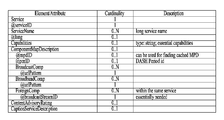
도시된 USBD 는 bundleDescription 루트 엘레멘트를 가질 수 있다. bundleDescription 루트 엘레멘트는 userServiceDescription 엘레멘트를 가질 수 있다. userServiceDescription 엘레멘트는 하나의 서비스에 대한 인스턴스일 수 있다.
userServiceDescription 엘레멘트는 @serviceId, @atsc:serviceId, @atsc:serviceStatus, @atsc:fullMPDUri, @atsc:sTSIDUri, name, serviceLanguage, atsc:capabilityCode 및/또는 deliveryMethod 를 포함할 수 있다.
@serviceId는 BSID의 범위 내에서 유일한 서비스를 식별하는 전 세계적으로 유일한 URI일 수 있다. 해당 파라미터는 ESG 데이터 (Service@globalServiceID)와 관련시키는 데 사용될 수 있다.
@atsc:serviced는 LLS (SLT)에서 해당하는 서비스 엔트리에 대한 레퍼런스이다. 해당 성질의 값은 해당 엔트리에 할당된 serviceId의 값과 동일하다.
@atsc:serviceStatus는 해당 서비스의 상태는 특정할 수 있다. 그 값은 해당 서비스가 활성화되어 있는지 비활성화되어 있는지를 나타낸다. "1" (참)로 설정되면, 서비스가 활성화되어 있다는 것을 나타낸다. 이 필드가 사용되지 않는 경우, 디폴트 값 1 로 설정될 수 있다.
@atsc:fullMPDUri는 브로드캐스트 상에서 선택적으로, 또한 브로드밴드 상에서 전달되는 서비스의 컨텐츠 컴포넌트에 대한 디스크립션을 포함하는 MPD 분할을 레퍼런싱할 수 있다.
@atsc:sTSIDUri는 해당 서비스의 컨텐츠를 전달하는 전송 세션에 액세스 관련 파라미터를 제공하는 STSID 분할을 레퍼런싱할 수 있다.
name은 lang 성질에 의해 주어지는 서비스의 네임을 나타낼 수 있다. name 엘레먼트는 서비스 네임의 언어를 나타내는 lang 성질을 포함할 수 있다. 언어는 XML 데이터타입에 따라 특정될 수 있다.
serviceLanguage는 서비스의 이용 가능한 언어를 나타낼 수 있다. 언어는 XML 데이터타입에 따라 특정될 수 있다.
atsc:capabilityCode는 수신기가 해당 서비스의 컨텐츠의 유의미한 프레젠테이션을 생성할 수 있도록 요구되는 캐패빌리티를 특정할 수 있다. 실시예에 따라 본 필드는 기 정의된 캐패빌리티 그룹을 특정할 수도 있다. 여기서 캐패빌리티 그룹은 유의미한 프리젠테이션을 위한 캐패빌리티 성질들 값의 그룹일 수 있다. 본 필드는 실시예에 따라 생략될 수 있다.
deliveryMethod는 액세스의 브로드캐스트 및 (선택적으로) 브로드밴드 모드 상에서 서비스의 컨텐츠에 속하는 정보에 관련된 트랜스포트의 컨테이너일 수 있다. 해당 서비스에 포함되는 데이터에 있어서, 그 데이터를 N 개라 하면, 그 각각의 데이터들에 대한 딜리버리 방법들이, 이 엘레멘트에 의해 기술될 수 있다. deliveryMethod 엘레멘트는 r12:broadcastAppService 엘레멘트와 r12:unicastAppService 엘레멘트를 포함할 수 있다. 각각의 하위 엘레멘트들은 basePattern 엘레멘트를 하위 엘레멘트로 가질 수 있다.
r12:broadcastAppService는 소속된 미디어 프레젠테이션의 모든 기간에 걸쳐 서비스에 속하는 해당 미디어 컴포넌트를 포함하는 다중화된 또는 비다중화된 형태의 브로드캐스트 상에서 전달되는 DASH 레프레젠테이션일 수 있다. 즉, 각각의 본 필드들은, 방송망을 통해 전달되는 DASH 레프레젠테이션(representation) 들을 의미할 수 있다.
r12:unicastAppService는 소속된 미디어 프레젠테이션의 모든 기간에 걸쳐 서비스에 속하는 구성 미디어 컨텐츠 컴포넌트를 포함하는 다중화된 또는 비다중화된 형태의 브로드밴드 상에서 전달되는 DASH 레프레젠테이션일 수 있다. 즉, 각각의 본 필드들은, 브로드밴드를 통해 전달되는 DASH 레프레젠테이션(representation) 들을 의미할 수 있다.
basePattern은 포함된 기간에 페어런트 레프레젠테이션의 미디어 분할을 요구하기 위해 DASH 클라이언트에 의해 사용되는 분할 URL의 모든 부분에 대해 매칭되도록 수신기에 의해 사용되는 문자 패턴일 수 있다. 매치는 해당 요구된 미디어 분할이 브로드캐스트 트랜스포트 상에서 전달되는 것을 암시한다. 각각의 r12:broadcastAppService 엘레멘트와 r12:unicastAppService 엘레멘트로 표현되는 DASH 레프레젠테이션을 전달받을 수 있는 URL 주소에 있어서, 그 URL 의 일부분 등은 특정한 패턴을 가질 수 있는데, 그 패턴이 본 필드에 의해 기술될 수 있다. 이 정보를 통하여 일정부분 데이터에 대한 구분이 가능할 수 있다. 제시된 디폴트 값들은 실시예에 따라 변경될 수 있다. 도시된 사용(use) 열은 각 필드에 관한 것으로, M 은 필수 필드, O 는 옵셔널 필드, OD 는 디폴트 값을 가지는 옵셔널 필드, CM 은 조건부 필수 필드를 의미할 수 있다. 0...1 내지 0...N 은 해당 필드들의 가능 개수를 의미할 수 있다.
도 6 은 본 발명의 일 실시예에 따른 ROUTE/DASH 를 위한 STSID 프래그먼트를 도시한 도면이다.
이하, 본 도면에 도시된 STSID 의 구체적인 내용에 대해 설명한다.
STSID는 서비스의 컨텐츠 컴포넌트를 전달하는 전송 세션에 대한 전체적인 세션 디스크립트 정보를 제공하는 SLS XML 분할일 수 있다. STSID는 서비스의 미디어 컨텐츠 컴포넌트가 전달되는 구성 LCT 세션 및 0개 이상의 ROUTE 세션에 대한 전체적인 전송 세션 디스크립트 정보를 포함하는 SLS 메타데이터 분할이다. STSID는 또한 LCT 세션에서 전달되는 컨텐츠 컴포넌트 및 페이로드 포맷에 대한 추가 정보뿐만 아니라 서비스의 LCT 세션에서 전달되는 딜리버리 오브젝트 또는 오브젝트 플로우에 대한 파일 메타데이터를 포함한다.
STSID 분할의 각 경우는 userServiceDescription 엘레먼트의 @atsc:sTSIDUri 성질에 의해 USBD 분할에서 레퍼런싱된다. 도시된 본 발명의 일 실시예에 따른 STSID 는 XML 도큐먼트 형태로 표현되었다. 실시예에 따라, STSID 는 바이너리 포맷 또는 XML 도큐먼트의 형태로 표현될 수 있다.
도시된 STSID 는 도시된 STSID 는 STSID 루트 엘레멘트를 가질 수 있다. STSID 루트 엘레멘트는 @serviceId 및/또는 RS 를 포함할 수 있다.
@serviceID는 USD에서 서비스 엘레멘트에 해당하는 레퍼런스일 수 있다. 해당 성질의 값은 service_id의 해당 값을 갖는 서비스를 레퍼런싱할 수 있다.
RS 엘레멘트는 해당 서비스 데이터들을 전달하는 ROUTE 세션에 대한 정보를 가질 수 있다. 복수개의 ROUTE 세션을 통해 서비스 데이터 내지 서비스 컴포넌트들이 전달될 수 있으므로, 본 엘레멘트는 1 내지 N 개의 개수를 가질 수 있다.
RS 엘레멘트는 @bsid, @sIpAddr, @dIpAddr, @dport, @PLPID 및/또는 LS 를 포함할 수 있다.
@bsid는 broadcastAppService의 컨텐츠 컴포넌트가 전달되는 브로드캐스트 스트림의 식별자일 수 있다. 해당 성질이 존재하지 않으면, 디폴트 브로드캐스트 스트림의 PLP가 해당 서비스에 대한 SLS 분할을 전달하는 것일 수 있다. 그 값은 SLT에서 broadcast_stream_id와 동일할 수 있다.
@sIpAddr은 소스 IP 어드레스를 나타낼 수 있다. 여기서 소스 IP 어드레스는, 해당 서비스에 포함되는 서비스 컴포넌트를 전달하는 ROUTE 세션의 소스 IP 어드레스일 수 있다. 전술한 바와 같이 하나의 서비스의 서비스 컴포넌트들은 복수개의 ROUTE 세션을 통해 전달될 수도 있다. 그 때문에, 해당 STSID 가 전달되는 ROUTE 세션이 아닌 다른 ROUTE 세션으로 그 서비스 컴포넌트가 전송될 수도 있다. 따라서, ROUTE 세션의 소스 IP 어드레스를 지시하기 위하여 본 필드가 사용될 수 있다. 본 필드의 디폴트 값은 현재 ROUTE 세션의 소스 IP 어드레스일 수 있다. 다른 ROUTE 세션을 통해 전달되는 서비스 컴포넌트가 있어 그 ROUTE 세션을 지시해야 되는 경우에는 본 필드 값은 그 ROUTE 세션의 소스 IP 어드레스 값일 수 있다. 이 경우 본 필드는 M, 즉 필수 필드일 수 있다.
@dIpAddr은 데스티네이션 IP 어드레스를 나타낼 수 있다. 여기서 데스티네이션 IP 어드레스는, 해당 서비스에 포함되는 서비스 컴포넌트를 전달하는 ROUTE 세션의 데스티네이션 IP 어드레스일 수 있다. @sIpAddr 에서 설명한 것과 같은 경우를 위해, 본 필드는 서비스 컴포넌트를 전달하는 ROUTE 세션의 데스티네이션 IP 어드레스를 지시할 수 있다. 본 필드의 디폴트 값은 현재 ROUTE 세션의 데스티네이션 IP 어드레스일 수 있다. 다른 ROUTE 세션을 통해 전달되는 서비스 컴포넌트가 있어 그 ROUTE 세션을 지시해야 되는 경우에는 본 필드 값은 그 ROUTE 세션의 데스티네이션 IP 어드레스 값일 수 있다. 이 경우 본 필드는 M, 즉 필수 필드일 수 있다.
@dport는 데스티네이션 포트를 나타낼 수 있다. 여기서 데스티네이션 포트는, 해당 서비스에 포함되는 서비스 컴포넌트를 전달하는 ROUTE 세션의 데스티네이션 포트일 수 있다. @sIpAddr 에서 설명한 것과 같은 경우를 위해, 본 필드는 서비스 컴포넌트를 전달하는 ROUTE 세션의 데스티네이션 포트를 지시할 수 있다. 본 필드의 디폴트 값은 현재 ROUTE 세션의 데스티네이션 포트 넘버일 수 있다. 다른 ROUTE 세션을 통해 전달되는 서비스 컴포넌트가 있어 그 ROUTE 세션을 지시해야 되는 경우에는 본 필드 값은 그 ROUTE 세션의 데스티네이션 포트 넘버 값일 수 있다. 이 경우 본 필드는 M, 즉 필수 필드일 수 있다.
@PLPID 는 RS 로 표현되는 ROUTE 세션을 위한 PLP 의 ID 일 수 있다. 디폴트 값은 현재 STSID 가 포함된 LCT 세션의 PLP 의 ID 일 수 있다. 실시예에 따라 본 필드는 해당 ROUTE 세션에서 STSID 가 전달되는 LCT 세션을 위한 PLP 의 ID 값을 가질 수도 있고, 해당 ROUTE 세션을위한 모든 PLP 들의 ID 값들을 가질 수도 있다.
LS 엘레멘트는 해당 서비스 데이터들을 전달하는 LCT 세션에 대한 정보를 가질 수 있다. 복수개의 LCT 세션을 통해 서비스 데이터 내지 서비스 컴포넌트들이 전달될 수 있으므로, 본 엘레멘트는 1 내지 N 개의 개수를 가질 수 있다.
LS 엘레멘트는 @tsi, @PLPID, @bw, @startTime, @endTime, SrcFlow 및/또는 RprFlow 를 포함할 수 있다.
@tsi 는 해당 서비스의 서비스 컴포넌트가 전달되는 LCT 세션의 TSI 값을 지시할 수 있다.
@PLPID 는 해당 LCT 세션을 위한 PLP 의 ID 정보를 가질 수 있다. 이 값은 기본 ROUTE 세션 값을 덮어쓸 수도 있다.
@bw 는 최대 밴드위스 값을 지시할 수 있다. @startTime 은 해당 LCT 세션의 스타트 타임(Start time)을 지시할 수 있다. @endTime 은 해당 LCT 세션의 엔드 타임(End time)을 지시할 수 있다. SrcFlow 엘레멘트는 ROUTE 의 소스 플로우에 대해 기술할 수 있다. RprFlow 엘레멘트는 ROUTE 의 리페어 플로우에 대해 기술할 수 있다.
제시된 디폴트 값들은 실시예에 따라 변경될 수 있다. 도시된 사용(use) 열은 각 필드에 관한 것으로, M 은 필수 필드, O 는 옵셔널 필드, OD 는 디폴트 값을 가지는 옵셔널 필드, CM 은 조건부 필수 필드를 의미할 수 있다. 0...1 내지 0...N 은 해당 필드들의 가능 개수를 의미할 수 있다.
이하, ROUTE/DASH 를 위한 MPD (Media Presentation Description) 에 대해 설명한다.
MPD는 방송사에 의해 정해진 주어진 듀레이션의 리니어 서비스에 해당하는 DASH 미디어 프레젠테이션의 공식화된 디스크립션을 포함하는 SLS 메타데이터 분할이다 (예를 들면, 어떤 기간 동안의 하나의 TV 프로그램 또는 연속적인 리니어 TV 프로그램의 집합). MPD의 컨텐츠는 미디어 프레젠테이션 내에서 식별된 리소스에 대한 컨텍스트 및 분할에 대한 소스 식별자를 제공한다. MPD 분할의 데이터 구조 및 시맨틱스는 MPEG DASH에 의해 정의된 MPD에 따를 수 있다.
MPD에서 전달되는 하나 이상의 DASH 레프레젠테이션은 브로드캐스트 상에서 전달될 수 있다. MPD는 하이브리드 서비스의 경우와 같은 브로드밴드 상에서 전달되는 추가 레프레젠테이션을 서술하거나, 브로드캐스트 신호 악화 (예를 들면, 터널 속 주행)로 인한 브로드캐스트에서 브로드캐스트로의 핸드오프에서 서비스 연속성을 지원할 수 있다.
도 7 은 본 발명의 일 실시예에 따른 MMT 를 위한 USBD/USD 프래그먼트를 도시한 도면이다.
리니어 서비스를 위한 MMT SLS는 USBD 분할 및 MP 테이블을 포함한다. MP 테이블은 전술한 바와 같다. USBD 분할은 서비스 식별, 장치 성능 정보, 서비스 및 구성 미디어 컴포넌트에 액세스하는 데 요구되는 다른 SLS 분할에 대한 참조, 수신기가 서비스 컴포넌트의 전송 모드 (브로드캐스트 및/또는 브로드밴드)를 결정할 수 있게 하는 메타데이터를 포함한다. USBD에 의해 참조되는 MPU 컴포넌트에 대한 MP 테이블은 서비스의 미디어 컨텐츠 컴포넌트가 전달되는 MMTP 세션에 대한 전송 세션 디스크립션 및 MMTP 세션에서 전달되는 에셋의 디스크립션을 제공한다.
MPU 컴포넌트에 대한 SLS의 스트리밍 컨텐츠 시그널링 컴포넌트는 MMT에서 정의된 MP 테이블에 해당한다. MP 테이블은 각 에셋이 단일 서비스 컴포넌트에 해당하는 MMT 에셋의 리스트 및 해당 컴포넌트에 대한 위치 정보의 디스크립션을 제공한다.
USBD 분할은 ROUTE 프로토콜 및 브로드밴드에 의해 각각 전달되는 서비스 컴포넌트에 대해 전술한 바와 같은 STSID 및 MPD에 대한 참조도 포함할 수 있다. 실시예에 따라, MMT 를 통한 딜리버리에 있어 ROUTE 프로토콜을 통해 전달되는 서비스 컴포넌트란 NRT 등의 데이터이므로, 이 경우에 있어 MPD 는 필요치 않을 수 있다. 또한, MMT 를 통한 딜리버리에 있어 브로드밴드를 통해 전달되는 서비스 컴포넌트는 어떤 LCT 세션을 통해 전달되는지에 대한 정보가 필요치 않으므로 STSID 는 필요치 않을 수 있다. 여기서, MMT 패키지는 MMT 를 이용하여 전달되는, 미디어 데이터의 논리적 콜렉션일 수 있다. 여기서, MMTP 패킷은 MMT 를 이용하여 전달되는 미디어 데이터의 포맷된 유닛을 의미할 수 있다. MPU (Media Processing Unit) 은 독립적으로 디코딩 가능한 타임드/논타임드 데이터의 제네릭 컨테이너를 의미할 수 있다. 여기서, MPU에서의 데이터는 미디어 코덱 애그노스틱이다.
이하, 본 도면에 도시된 USBD/USD 의 구체적인 내용에 대해 설명한다.
도시된 USBD 프래그먼트는 본 발명의 일 실시예이며, 도시되지 않은 기본적인 USBD 프래그먼트의 필드들이 실시예에 따라 더 추가될 수도 있다. 전술한 바와 같이 도시된 USBD 프래그먼트는 확장된 형태로서 기본 구조에서 더 추가된 필드들을 가질 수 있다.
도시된 본 발명의 일 실시예에 따른 USBD 는 XML 도큐먼트 형태로 표현되었다. 실시예에 따라, USBD 는 바이너리 포맷 또는 XML 도큐먼트의 형태로 표현될 수 있다.
도시된 USBD 는 bundleDescription 루트 엘레멘트를 가질 수 있다. bundleDescription 루트 엘레멘트는 userServiceDescription 엘레멘트를 가질 수 있다. userServiceDescription 엘레멘트는 하나의 서비스에 대한 인스턴스일 수 있다.
userServiceDescription 엘레멘트는 @serviceId, @atsc:serviceId, name, serviceLanguage, atsc:capabilityCode, atsc:Channel, atsc:mpuComponent, atsc:routeComponent, atsc:broadband Component 및/또는 atsc:ComponentInfo 를 포함할 수 있다.
여기서, @serviceId, @atsc:serviceId, name, serviceLanguage, atsc:capabilityCode 는 전술한 것과 같을 수 있다. name 필드 밑의 lang 필드 역시 전술한 것과 같을 수 있다. atsc:capabilityCode 는 실시예에 따라 생략될 수 있다.
userServiceDescription 엘레멘트는, 실시예에 따라 atsc:contentAdvisoryRating 엘레멘트를 더 포함할 수 있다. 이 엘레멘트는 옵셔널 엘레멘트일 수 있다. atsc:contentAdvisoryRating는 컨텐츠 자문 순위를 특정할 수 있다. 본 필드는 도면에 도시되지 않았다.
atsc:Channel 은 서비스의 채널에 대한 정보를 가질 수 있다. atsc:Channel 엘레멘트는 @atsc:majorChannelNo, @atsc:minorChannelNo, @atsc:serviceLang, @atsc:serviceGenre, @atsc:serviceIcon 및/또는 atsc:ServiceDescription 를 포함할 수 있다. @atsc:majorChannelNo, @atsc:minorChannelNo, @atsc:serviceLang 는 실시예에 따라 생략될 수 있다.
@atsc:majorChannelNo는 서비스의 주 채널 넘버를 나타내는 성질이다.
@atsc:minorChannelNo는 서비스의 부 채널 넘버를 나타내는 성질이다.
@atsc:serviceLang는 서비스에서 사용되는 주요 언어를 나타내는 성질이다.
@atsc:serviceGenre는 서비스의 주요 장르를 나타내는 성질이다.
@atsc:serviceIcon는 해당 서비스를 표현하는 데 사용되는 아이콘에 대한 URL을 나타내는 성질이다.
atsc:ServiceDescription은 서비스 디스크립션을 포함하며 이는 다중 언어일 수 있다. atsc:ServiceDescription은 @atsc:serviceDescrText 및/또는 @atsc:serviceDescrLang를 포함할 수 있다.
@atsc:serviceDescrText는 서비스의 디스크립션을 나타내는 성질이다.
@atsc:serviceDescrLang는 상기 serviceDescrText 성질의 언어를 나타내는 성질이다.
atsc:mpuComponent 는 MPU 형태로 전달되는 서비스의 컨텐츠 컴포넌트에 대한 정보를 가질 수 있다. atsc:mpuComponent 는 @atsc:mmtPackageId 및/또는 @atsc:nextMmtPackageId 를 포함할 수 있다.
@atsc:mmtPackageId는 MPU로 전달되는 서비스의 컨텐츠 컴포넌트에 대한 MMT 패키지를 레퍼런싱할 수 있다.
@atsc:nextMmtPackageId는 MPU로 전달되는 서비스의 컨텐츠 컴포넌트에 맞추어 @atsc:mmtPackageId에 의해 참조된 후에 사용되는 MMT 패키지를 레퍼런싱할 수 있다.
atsc:routeComponent 는 ROUTE 를 통해 전달되는 서비스의 컨텐츠 컴포넌트에 대한 정보를 가질 수 있다. atsc:routeComponent 는 @atsc:sTSIDUri, @sTSIDPlpId, @sTSIDDestinationIpAddress, @sTSIDDestinationUdpPort, @sTSIDSourceIpAddress, @sTSIDMajorProtocolVersion 및/또는 @sTSIDMinorProtocolVersion 를 포함할 수 있다.
@atsc:sTSIDUri는 해당 서비스의 컨텐츠를 전달하는 전송 세션에 액세스 관련 파라미터를 제공하는 STSID 분할을 레퍼런싱할 수 있다. 이 필드는 전술한 ROUTE 를 위한 USBD 에서의 STSID 를 레퍼런싱하기 위한 URI 와 같을 수 있다. 전술한 바와 같이 MMTP 에 의한 서비스 딜리버리에 있어서도, NRT 등을 통해 전달되는 서비스 컴포넌트들은 ROUTE 에 의해 전달될 수 있다. 이를 위한 STSID 를 레퍼런싱하기 위하여 본 필드가 사용될 수 있다.
@sTSIDPlpId는 해당 서비스에 대한 STSID를 전달하는 PLP의 PLP ID를 나타내는 정수를 표현하는 스트링일 수 있다. (디폴트: 현재 PLP)
@sTSIDDestinationIpAddress는 해당 서비스에 대한 STSID를 전달하는 패킷의 dottedIPv4 데스티네이션 어드레스를 포함하는 스트링일 수 있다. (디폴트: 현재 MMTP 세션의 소스 IP 어드레스)
@sTSIDDestinationUdpPort는 해당 서비스에 대한 STSID를 전달하는 패킷의 포트 넘버를 포함하는 스트링일 수 있다.
@sTSIDSourceIpAddress는 해당 서비스에 대한 STSID를 전달하는 패킷의 dottedIPv4 소스 어드레스를 포함하는 스트링일 수 있다.
@sTSIDMajorProtocolVersion은 해당 서비스에 대한 STSID를 전달하기 위해 사용되는 프로토콜의 주 버전 넘버를 나타낼 수 있다. 디폴트 값은 1이다.
@sTSIDMinorProtocolVersion은 해당 서비스에 대한 STSID를 전달하기 위해 사용되는 프로토콜의 부 버전 넘버를 나타낼 수 있다. 디폴트 값은 0이다.
atsc:broadbandComponent 는 브로드밴드를 통해 전달되는 서비스의 컨텐츠 컴포넌트에 대한 정보를 가질 수 있다. 즉, 하이브리드 딜리버리를 상정한 필드일 수 있다. atsc:broadbandComponent 는 @atsc:fullfMPDUri 를 더 포함할 수 있다.
@atsc:fullfMPDUri는 브로드밴드로 전달되는 서비스의 컨텐츠 컴포넌트에 대한 디스크립션을 포함하는 MPD 분할에 대한 레퍼런스일 수 있다.
atsc:ComponentInfo 는 서비스의 어베일러블한(available) 컴포넌트에 대한 정보를 가질 수 있다. 각각의 컴포넌트에 대한, 타입, 롤, 이름 등의 정보를 가질 수 있다. 각 컴포넌트(N개) 개수만큼 본 필드가 존재할 수 있다. atsc:ComponentInfo 는 @atsc:componentType, @atsc:componentRole, @atsc:componentProtectedFlag, @atsc:componentId 및/또는 @atsc:componentName 을 포함할 수 있다.
@atsc:componentType은 해당 컴포넌트의 타입을 나타내는 성질이다. 0의 값은 오디오 컴포넌트를 나타낸다. 1의 값은 비디오 컴포넌트를 나타낸다. 2의 값은 클로즈드 캡션 컴포넌트를 나타낸다. 3의 값은 어플리케이션 컴포넌트를 나타낸다. 4 내지 7의 값은 남겨둔다. 본 필드 값의 의미는 실시예에 따라 다르게 설정될 수도 있다.
@atsc:componentRole은 해당 컴포넌트의 역할 및 종류를 나타내는 성질이다.
오디오에 대해 (상기 componentType 성질이 0과 동일할 때), componentRole 성질의 값은 다음과 같다. 0 = Complete main, 1 = 음악 및 효과 (Music and Effects), 2 = 대화 (Dialog), 3 = 해설 (Commentary), 4 = 시각 장애 (Visually Impaired), 5 = 청각 장애 (Hearing Impaired), 6 = 보이스오버 (VoiceOver), 7254= reserved, 255 = 알 수 없음 (unknown).
오디오에 대해 (상기 componentType 성질이 1과 동일할 때), componentRole 성질의 값은 다음과 같다. 0 = Primary video, 1= 대체 카메라 뷰 (Alternative camera view), 2 = 다른 대체 비디오 컴포넌트 (Other alternative video component), 3 = 수화 삽입 (Sign language inset), 4 = Follow subject video, 5 = 3D 비디오 좌측 뷰 (3D video left view), 6 = 3D 비디오 우측 뷰 (3D video right view), 7 = 3D 비디오 깊이 정보 (3D video depth information), 8 = Part of video array <x,y> of <n,m>, 9 = FollowSubject metadata, 10254 = reserved, 255 = 알 수 없음 (unknown).
클로즈드 캡션 컴포넌트에 대해, (상기 componentType 성질이 2와 동일할 때), componentRole 성질의 값은 다음과 같다. 0 = Normal, 1 = Easy reader, 2254 = reserved, 255 = 알 수 없음 (unknown).
상기 componentType 성질의 값이 3과 7 사이이면, componentRole 255와 동일할 수 있다. 본 필드 값의 의미는 실시예에 따라 다르게 설정될 수도 있다.
@atsc:componentProtectedFlag는 해당 컴포넌트가 보호되는지 (예를 들면, 암호화되는지)를 나타내는 성질이다. 해당 플레그가 1의 값으로 설정되면, 해당 컴포넌트는 보호된다 (예를 들면, 암호화된다). 해당 플레그가 0의 값으로 설정되면, 해당 컴포넌트는 보호되지 않는다 (예를 들면, 암호화되지 않는다). 존재하지 않는 경우, componentProtectedFlag 성질의 값은 0과 같은 것으로 추론된다. 본 필드 값의 의미는 실시예에 따라 다르게 설정될 수도 있다.
@atsc:componentId는 해당 컴포넌트의 식별자를 나타내는 성질이다. 해당 성질의 값은 해당 컴포넌트에 해당하는 MP 테이블에서 asset_id와 동일할 수 있다.
@atsc:componentName은 해당 컴포넌트의 사람이 판독 가능한 이름을 나타내는 성질이다.
제시된 디폴트 값들은 실시예에 따라 변경될 수 있다. 도시된 사용(use) 열은 각 필드에 관한 것으로, M 은 필수 필드, O 는 옵셔널 필드, OD 는 디폴트 값을 가지는 옵셔널 필드, CM 은 조건부 필수 필드를 의미할 수 있다. 0...1 내지 0...N 은 해당 필드들의 가능 개수를 의미할 수 있다.
이하, MMT 를 위한 MPD (Media Presentation Description) 에 대해 설명한다.
MPD는 방송사에 의해 정해진 주어진 듀레이션의 리니어 서비스에 해당하는 SLS 메타데이터 분할이다 (예를 들면, 하나의 TV 프로그램, 또는 어떤 기간 동안의 연속적인 리니어 TV 프로그램의 집합). MPD의 컨텐츠는 분할에 대한 리소스 식별자 및 미디어 프레젠테이션 내에서 식별된 리소스에 대한 컨텍스트를 제공한다. MPD의 데이터 구조 및 시맨틱스는 MPEG DASH에 의해 정의된 MPD에 따를 수 있다.
본 발명의 실시예에 있어서, MMTP 세션에 의해 전달되는 MPD는 하이브리드 서비스의 경우와 같은 브로드밴드 상에서 전달되는 레프레젠테이션을 서술하거나, 브로드캐스트 신호 악화 (예를 들면, 산 아래나 터널 속 주행)로 인한 브로드캐스트에서 브로드캐스트로의 핸드오프에서 서비스 연속성을 지원할 수 있다.
이하, MMT 를 위한 MMT 시그널링 메시지에 대해서 설명한다.
MMTP 세션이 스트리밍 서비스를 전달하기 위해서 사용되면, MMT에 의해 정의된 MMT 시그널링 메시지는 MMT에 의해 정의된 시그널링 메시지 모드에 따라 MMTP 패킷에 의해 전달된다. 에셋을 전달하는 MMTP 패킷과 동일한 packet_id 값으로 설정될 수 있는, 에셋에 특정한 MMT 시그널링 메시지를 전달하는 MMTP 패킷을 제외하고 SLS를 전달하는 MMTP 패킷의 packet_id 필드의 값은 "00"으로 설정된다. 각 서비스에 대한 적절한 패킷을 레퍼런싱하는 식별자는 전술한 바와 같이 USBD 분할에 의해 시그널링된다. 매칭하는 MMT_package_id를 갖는 MPT 메시지는 SLT에서 시그널링되는 MMTP 세션 상에서 전달될 수 있다. 각 MMTP 세션은 그 세션에 특정한 MMT 시그널링 메시지 또는 MMTP 세션에 의해 전달되는 각 에셋을 전달한다.
즉, SLT 에서 특정 서비스에 대한 SLS 를 가지는 패킷의 IP 데스티네이션 어드레스/포트 넘버 등을 특정하여 MMTP 세션의 USBD 에 접근할 수 있다. 전술한 바와 같이 SLS 를 운반하는 MMTP 패킷의 패킷 ID 는 00 등 특정값으로 지정될 수 있다. USBD 의 전술한 패키지 ID 정보를 이용하여, 매칭되는 패키지 ID 를 가지는 MPT 메시지에 접근할 수 있다. MPT 메시지는 후술하는 바와 같이 각 서비스 컴포넌트/에셋에 접근하는데 사용될 수 있다.
다음의 MMTP 메시지는 SLT에서 시그널링되는 MMTP 세션에 의해 전달될 수 있다.
MPT 메시지: 이 메시지는 모든 에셋의 리스트 및 MMT에 의해 정의된 바와 같은 그것들의 위치 정보를 포함하는 MP 테이블을 전달한다. 에셋이 MP 테이블을 전달하는 현 PLP와 다른 PLP에 의해 전달되면, 해당 에셋을 전달하는 PLP의 식별자는 PLP 식별자 디스크립터를 사용한 MP 테이블에서 제공될 수 있다. PLP 식별자 디스크립터에 대해서는 후술한다.
MMT ATSC3 (MA3) message mmt_atsc3_message(): 이 메시지는 전술한 바와 같이 SLS를 포함하는 서비스에 특정한 시스템 메타데이터를 전달한다. mmt_atsc3_message()에 대해서는 후술한다.
다음의 MMTP 메시지는 필요한 경우 SLT에서 시그널링된 MMTP 세션에 의해 전달될 수 있다.
MPI 메시지: 이 메시지는 프레젠테이션 정보의 모든 다큐먼트 또는 일부 다큐먼트를 포함하는 MPI 테이블을 전달한다. MPI 테이블과 관련된 MP 테이블은 이 메시지에 의해 전달될 수 있다.
CRI (clock relation information) 메시지: 이 메시지는 NTP 타임스탬프와 MPEG2 STC 사이의 매핑을 위한 클록 관련 정보를 포함하는 CRI 테이블을 전달한다. 실시예에 따라 CRI 메시지는 해당 MMTP 세션을 통해 전달되지 않을 수 있다.
다음의 MMTP 메시지는 스트리밍 컨텐츠를 전달하는 각 MMTP 세션에 의해 전달될 수 있다.
가상적인 수신기 버퍼 모델 메시지: 이 메시지는 버퍼를 관리하기 위해 수신기에 의해 요구되는 정보를 전달한다.
가상적인 수신기 버퍼 모델 제거 메시지: 이 메시지는 MMT 디캡슐레이션 버퍼를 관리하기 위해 수신기에 의해 요구되는 정보를 전달한다.
이하, MMT 시그널링 메시지 중 하나인 mmt_atsc3_message() 에 대해서 설명한다. MMT 시그널링 메시지인 mmt_atsc3_message()는 전술한 본 발명에 따라 서비스에 특정한 정보를 전달하기 위해 정의된다. 본 시그널링 메시지는 MMT 시그널링 메시지의 기본적인 필드인 메시지 ID, 버전 및/또는 길이(length) 필드를 포함할 수 있다. 본 시그널링 메시지의 페이로드에는 서비스 ID 정보와, 컨텐트 타입, 컨텐트 버전, 컨텐트 컴프레션 정보 및/또는 URI 정보가 포함될 수 있다. 컨텐트 타입 정보는 본 시그널링 메시지의 페이로드에 포함되는 데이터의 타입을 지시할 수 있다. 컨텐트 버전 정보는 페이로드에 포함되는 데이터의 버전을, 컨텐트 컴프레션 정보는 해당 데이터에 적용된 컴프레션 타입을 지시할 수 있다. URI 정보는 본 메시지에 의해 전달되는 컨텐츠와 관련된 URI 정보를 가질 수 있다.
이하, PLP 식별자 디스크립터에 대해서 설명한다.
PLP 식별자 디스크립터는 전술한 MP 테이블의 디스크립터 중 하나로 사용될 수 있는 디스크립터이다. PLP 식별자 디스크립터는 에셋을 전달하는 PLP에 관한 정보를 제공한다. 에셋이 MP 테이블을 전달하는 현재 PLP와 다른 PLP에 의해 전달되면, PLP 식별자 디스크립터는 그 에셋을 전달하는 PLP를 식별하기 위해 관련된 MP 테이블에서 에셋 디스크립터로 사용될 수 있다. PLP 식별자 디스크립터는 PLP ID 정보 외에 BSID 정보를 더 포함할 수도 있다. BSID 는 이 디스크립터에 의해 기술되는 Asset 을 위한 MMTP 패킷을 전달하는 브로드캐스트 스트림의 ID 일 수 있다.
도 8 은 본 발명의 일 실시예에 따른 링크 레이어 프로토콜 아키텍쳐를 도시한 도면이다.
이하, 링크 레이어(Link Layer) 에 대해서 설명한다.
링크 레이어는 피지컬 레이어와 네트워크 레이어 사이의 레이어이며, 송신 측에서는 네트워크 레이어에서 피지컬 레이어로 데이터를 전송하고, 수신 측에서는 피지컬 레이어에서 네트워크 레이어로 데이터를 전송한다. 링크 레이어의 목적은 피지컬 레이어에 의한 처리를 위해 모든 입력 패킷 타입을 하나의 포맷으로 요약하는 것, 아직 정의되지 않은 입력 타입에 대한 유연성 및 추후 확장 가능성을 보장하는 것이다. 또한, 링크 레이어 내에서 처리하면, 예를 들면, 입력 패킷의 헤더에 있는 불필요한 정보를 압축하는 데 옵션을 제공함으로써, 입력 데이터가 효율적으로 전송될 수 있도록 보장된다. 인캡슐레이션, 콤프레션 등의 동작은 링크 레이어 프로토콜이라 불리고, 해당 프로토콜을 이용하여 생성된 패킷은 링크 레이어 패킷이라 불린다. 링크 레이어는 패킷 인캡슐레이션(packet encapsulation), 오버헤드 리덕션(Overhead Reduction) 및/또는 시그널링 전송(Signaling Transmission) 등의 기능을 수행할 수 있다.
이하, 패킷 인캡슐레이션에 대해서 설명한다. 링크 레이어 프로토콜은 IP 패킷 및 MPEG2 TS와 같은 것을 포함하는 모든 타입의 패킷의 인캡슐레이션을 가능하게 한다. 링크 레이어 프로토콜을 이용하여, 피지컬 레이어는 네트워크 레이어 프로토콜 타입과 독립적으로 하나의 패킷 포맷만 처리하면 된다 (여기서 네트워크 레이어 패킷의 일종으로 MPEG2 TS 패킷을 고려). 각 네트워크 레이어 패킷 또는 입력 패킷은 제네릭 링크 레이어 패킷의 페이로드로 변형된다. 추가적으로, 입력 패킷 사이즈가 특별히 작거나 큰 경우 피지컬 레이어 리소스를 효율적으로 이용하기 위해 연쇄 및 분할이 실행될 수 있다.
전술한 바와 같이 패킷 인캡슐레이션 과정에서 분할(segmentation) 이 활용될 수 있다. 네트워크 레이어 패킷이 지나치게 커서 피지컬 레이어에서 쉽게 처리하지 못하는 경우, 네트워크 레이어 패킷은 두 개 이상의 분할로 나누어진다. 링크 레이어 패킷 헤더는 송신 측에서 분할을 실행하고 수신 측에서 재결합을 실행하기 위해 프로토콜 필드를 포함한다. 네트워크 레이어 패킷이 분할되는 경우, 각 분할은 네트워크 레이어 패킷에서의 원래 위치와 같은 순서로 링크 레이어 패킷으로 인캡슐레이션 될 수 있다. 또한 네트워크 레이어 패킷의 분할을 포함하는 각 링크 레이어 패킷은 결과적으로 피지컬 레이어로 전송될 수 있다.
전술한 바와 같이 패킷 인캡슐레이션 과정에서 연쇄(concatenation) 또한 활용될 수 있다. 링크 레이어 패킷의 페이로드가 여러 네트워크 레이어 패킷을 포함할 정도로 네트워크 레이어 패킷이 충분히 작은 경우, 링크 레이어 패킷 헤더는 연쇄를 실행하기 위해 프로토콜 필드를 포함한다. 연쇄는 다수의 작은 크기의 네트워크 레이어 패킷을 하나의 페이로드로 결합한 것이다. 네트워크 레이어 패킷들이 연쇄되면, 각 네트워크 레이어 패킷은 원래의 입력 순서와 같은 순서로 링크 레이어 패킷의 페이로드로 연쇄될 수 있다. 또한, 링크 레이어 패킷의 페이로드를 구성하는 각 패킷은 패킷의 분할이 아닌 전체 패킷일 수 있다.
이하, 오버헤드 리덕션에 대해서 설명한다. 링크 레이어 프로토콜의 사용으로 인해 피지컬 레이어 상에서 데이터의 전송에 대한 오버헤드가 크게 감소할 수 있다. 본 발명에 따른 링크 레이어 프로토콜은 IP 오버헤드 리덕션 및/또는 MPEG2 TS 오버헤드 리덕션을 제공할 수 있다. IP 오버헤드 리덕션에 있어서, IP 패킷은 고정된 헤더 포맷을 가지고 있으나, 통신 환경에서 필요한 일부 정보는 브로드캐스트 환경에서 불필요할 수 있다. 링크 레이어 프로토콜은 IP 패킷의 헤더를 압축함으로써 브로드캐스트 오버헤드를 줄이는 메커니즘을 제공한다. MPEG2 TS 오버헤드 리덕션에 있어서, 링크 레이어 프로토콜은 싱크 바이트 제거, 널 패킷 삭제 및/또는 공통 헤더 제거 (압축)을 제공한다. 우선, 싱크 바이트 제거는 TS 패킷당 하나의 바이트의 오버헤드 리덕션을 제공하고, 다음으로, 널 패킷 삭제 메커니즘은 수신기에서 재삽입될 수 있는 방식으로 188 바이트의 널 TS 패킷을 제거한다. 마지막으로, 공통 헤더 제거 메커니즘이 제공된다.
시그널링 전송에 대해서, 링크 레이어 프로토콜은 시그널링 패킷을 위한 특정 포맷이, 링크 레이어 시그널링을 전송하기 위하여 제공될 수 있다. 이에 관해서는 후술한다.
도시된 본 발명의 일 실시예에 따른 링크 레이어 프로토콜 아키텍쳐에서, 링크 레이어 프로토콜은 입력 패킷으로 IPv4, MPEG2 TS 등과 같은 입력 네트워크 레이어 패킷을 취한다. 향후 확장은 다른 패킷 타입과 링크 레이어에서 입력될 수 있는 프로토콜을 나타낸다. 링크 레이어 프로토콜은 피지컬 레이어에서 특정 채널에 대한 매핑에 관한 정보를 포함하는 모든 링크 레이어 시그널링에 대한 시그널링 및 포맷을 특정한다. 도면은 ALP가 어떻게 다양한 헤더 컴프레션 및 삭제 알고리즘을 통해 전송 효율을 향상시키기 위해 메커니즘을 포함하는지 나타낸다. 또한 링크 레이어 프로토콜은 기본적으로 입력 패킷들을 인캡슐레이션할 수 있다.
도 9 는 본 발명의 일 실시예에 따른 링크 레이어 패킷의 베이스 헤더 구조를 도시한 도면이다. 이하, 헤더의 구조에 대해서 설명한다.
링크 레이어 패킷은 데이터 페이로드가 뒤따르는 헤더를 포함할 수 있다. 링크 레이어 패킷의 패킷은 베이스 헤더를 포함할 수 있고, 베이스 헤더의 컨트롤 필드에 따라 추가 헤더를 포함할 수 있다. 옵셔널 헤더의 존재는 추가 헤더의 플레그 필드로부터 지시된다. 실시예에 따라, 추가 헤더, 옵셔널 헤더의 존재를 나타내는 필드는 베이스 헤더에 위치할 수도 있다.
이하, 베이스 헤더의 구조에 대해서 설명한다. 링크 레이어 패킷 인캡슐레이션에 대한 베이스 헤더는 계층 구조를 갖는다. 베이스 헤더는 2바이트의 길이를 가질 수 있고, 링크 레이어 패킷 헤더의 최소 길이이다.
도시된 본 발명의 일 실시예에 따른 베이스 헤더는, Packet_Type 필드, PC 필드 및/또는 길이(length) 필드를 포함할 수 있다. 실시예에 따라 베이스 헤더는 HM 필드 또는 S/C 필드를 더 포함할 수 있다.
Packet_Type 필드는 링크 레이어 패킷으로의 인캡슐레이션 전의 입력 데이터의 패킷 타입 또는 원래의 프로토콜을 나타내는 3비트 필드이다. IPv4 패킷, 압축된 IP 패킷(compressed IP packet), 링크 레이어 시그널링 패킷, 및 그 밖의 타입의 패킷들이 이러한 베이스 헤더 구조를 가지며 인캡슐레이션 될 수 있다. 단, 실시예에 따라 MPEG2 TS 패킷은 이와 다른 특별한 구조를 가지며 인캡슐레이션 될 수 있다. Packet_Type의 값이 "000" "001" "100" 또는 "111" 이면, 이면, ALP 패킷의 원래의 데이터 타입은 IPv4 패킷, 압축 IP 패킷, 링크 레이어 시그널링 또는 익스텐션 패킷 중 하나이다. MPEG2 TS 패킷이 캡슐화되면, Packet_Type의 값은 "010"이 될 수 있다. 다른 Packet_Type 필드의 값들은 향후 사용을 위해 남겨둘 수 있다(reserved for future use).
Payload_Configuration (PC) 필드는 페이로드의 구성을 나타내는 1비트 필드일 수 있다. 0의 값은 링크 레이어 패킷이 하나의 전체 입력 패킷을 전달하고 다음 필드가 Header_Mode라는 것을 나타낼 수 있다. 1의 값은 링크 레이어 패킷이 하나 이상의 입력 패킷 (연쇄)이나 큰 입력 패킷 (분할)의 일부를 전달하며 다음 필드가 Segmentation_Concatenation이라는 것을 나타낼 수 있다.
Header_Mode (HM) 필드는 0으로 설정되는 경우 추가 헤더가 없다는 것을 나타내고 링크 레이어 패킷의 페이로드의 길이가 2048 바이트보다 작다는 것을 나타내는 1비트 필드일 수 있다. 이 수치는 실시예에 따라 변경될 수 있다. 1의 값은 아래에 정의된 하나의 패킷을 위한 추가 헤더가 길이 필드 다음에 존재한다는 것을 나타낼 수 있다. 이 경우, 페이로드의 길이는 2047 바이트보다 크고/크거나 옵션 피쳐가 사용될 수 있다 (서브 스트림 식별, 헤더 확장 등). 이 수치는 실시예에 따라 변경될 수 있다. 본 필드는 링크 레이어 패킷의 Payload_Configuration 필드가 0의 값을 가질 때만 존재할 수 있다.
Segmentation_Concatenation (S/C) 필드는 0으로 설정된 경우 페이로드가 입력 패킷의 세그먼트를 전달하고 아래에 정의되는 분할을 위한 추가 헤더가 길이 필드 다음에 존재한다는 것을 나타내는 1비트 필드일 수 있다. 1의 값은 페이로드가 하나보다 많은 완전한 입력 패킷을 전달하고 아래에 정의된 연쇄를 위한 추가 헤더가 길이 필드 다음에 존재한다는 것을 나타낼 수 있다. 본 필드는 ALP 패킷의 Payload_Configuration 필드의 값이 1일 때만 존재할 수 있다.
길이 필드는 링크 레이어 패킷에 의해 전달되는 페이로드의 바이트 단위의 길이의 11 LSBs (least significant bits)를 나타내는 11비트 필드일 수 있다. 다음의 추가 헤더에 Length_MSB 필드가 있으면, 길이 필드는 Length_MSB 필드에 연쇄되고 페이로드의 실제 총 길이를 제공하기 위해 LSB가 된다. 길이필드의 비트수는 11 비트외에 다른 비트로 변경될 수도 있다.
따라서 다음의 패킷 구조의 타입이 가능하다. 즉, 추가 헤더가 없는 하나의 패킷, 추가 헤더가 있는 하나의 패킷, 분할된 패킷, 연쇄된 패킷이 가능하다. 실시예에 따라 각 추가 헤더와 옵셔널 헤더, 후술할 시그널링 정보를 위한 추가헤더와 타입 익스텐션을 위한 추가헤더에 의한 조합으로, 더 많은 패킷 컨피규레이션이 가능할 수 있다.
도 10 은 본 발명의 일 실시예에 따른 링크 레이어 패킷의 추가 헤더 구조를 도시한 도면이다.
추가 헤더(additional header) 는 다양한 타입이 있을 수 있다. 이하 싱글 패킷을 위한 추가 헤더에 대해서 설명한다.
하나의 패킷에 대한 해당 추가 헤더는 Header_Mode (HM) ="1"인 경우 존재할 수 있다. 링크 레이어 패킷의 페이로드의 길이가 2047 바이트보다 크거나 옵션 필드가 사용되는 경우 Header_Mode (HM)는 1로 설정될 수 있다. 하나의 패킷의 추가 헤더(tsib10010)는 도면에 나타낸다.
Length_MSB 필드는 현재 링크 레이어 패킷에서 바이트 단위의 총 페이로드 길이의 MSBs (most significant bits)를 나타낼 수 있는 5비트 필드일 수 있고, 총 페이로드 길이를 얻기 위해 11 LSB를 포함하는 길이 필드에 연쇄된다. 따라서 시그널링될 수 있는 페이로드의 최대 길이는 65535 바이트이다. 길이필드의 비트수는 11 비트외에 다른 비트로 변경될 수도 있다. 또한 Length_MSB 필드 역시 비트수가 변경될 수 있으며 이에 따라 최대 표현가능한 페이로드 길이 역시 변경될 수 있다. 실시예에 따라 각 길이필드들은 페이로드가 아닌 전체 링크 레이어 패킷의 길이를 지시할 수도 있다.
Substream Identifier Flag (SIF) 필드는 HEF (Header Extension Flag) 필드 후에 SID (substream ID)가 존재하는지 나타낼 수 있는 1비트 필드가 될 수 있다. 링크 레이어 패킷에 SID가 없으면, SIF 필드는 0으로 설정될 수 있다. 링크 레이어 패킷에서 HEF 필드 후에 SID가 존재하면, SIF는 1로 설정될 수 있다. SID에 대한 자세한 내용은 후술한다.
HEF 필드는 1로 설정되는 경우 추후 확장을 위해 추가 헤더가 존재한다는 것을 나타낼 수 있는 1비트 필드가 될 수 있다. 0의 값은 이 확장 필더가 존재하지 않는다는 것을 나타낼 수 있다.
이하, 분할(segmentation) 이 활용되는 경우에 있어서 추가 헤더에 대해서 설명한다.
Segmentation_Concatenation (S/C) ="0"인 경우 추가 헤더(tsib10020)가 존재할 수 있다. Segment_Sequence_Number는 링크 레이어 패킷에 의해 전달되는 해당 분할의 순서를 나타낼 수 있는 5비트의 무부호 정수가 될 수 있다. 입력 패킷의 첫 번째 분할을 전달하는 링크 레이어 패킷에 대해, 해당 필드의 값은 0x0으로 설정될 수 있다. 해당 필드는 분할될 입력 패킷에 속하는 각 추가 세그먼트마다 1씩 증분될 수 있다.
LSI (Last_Segment_Indicator)는 1로 설정되는 경우 해당 페이로드에 있는 분할이 입력 패킷의 마지막 것임을 나타낼 수 있는 1비트 필드일 수 있다. 0의 값은 그것이 마지막 분할이 아님을 나타낼 수 있다.
SIF (Substream Identifier Flag)는 SID가 HEF 필드 후에 존재하는지 나타낼 수 있는 1비트 필드가 될 수 있다. 링크 레이어 패킷에 SID가 존재하지 않으면, SIF 필드는 0으로 설정될 수 있다. 링크 레이어 패킷에서 HEF 필드 후에 SID가 존재하면, SIF는 1로 설정될 수 있다.
HEF 필드는 1로 설정되는 경우 링크 레이어 헤더의 추후 확장을 위해 추가 헤더 후에 옵셔널 헤더 확장이 존재한다는 것을 나타낼 수 있는 1비트 필드일 수 있다. 0의 값은 옵셔널 헤더 확장이 존재하지 않는다는 것을 나타낼 수 있다.
실시예에 따라 각 분할된 세그먼트가 동일한 입력 패킷으로부터 생성되었음을 지시하는 패킷 ID 필드가 추가될 수도 있다. 이 필드는 분할된 세그먼트가 순서대로 전송된다면 필요치 않아 생략될 수 있다.
이하, 연쇄(concatenation) 이 활용되는 경우에 있어서 추가 헤더에 대해서 설명한다.
Segmentation_Concatenation (S/C) ="1"인 경우 추가 헤더(tsib10030)가 존재할 수 있다.
Length_MSB는 해당 링크 레이어 패킷에서 바이트 단위의 페이로드 길이의 MSB 비트를 나타낼 수 있는 4비트 필드일 수 있다. 해당 페이로드의 최대 길이는 연쇄를 위해 32767 바이트가 된다. 전술한 바와 마찬가지로 자세한 수치는 변경될 수 있다.
Count 필드는 링크 레이어 패킷에 포함된 패킷의 수를 나타낼 수 있는 필드일 수 있다. 링크 레이어 패킷에 포함된 패킷의 수에 해당하는 2는 해당 필드에 설정될 수 있다. 따라서, 링크 레이어 패킷에서 연쇄된 패킷의 최대값은 9이다. Count 필드가 그 개수를 지시하는 방법은 실시예마다 다를 수 있다. 즉, 1 부터 8 까지의 개수가 지시될 수도 있다.
HEF 필드는 1로 설정되는 경우 링크 레이어 헤더의 향후 확장을 위한 추가 헤더 후에 옵셔널 헤더 확장이 존재한다는 것을 나타낼 수 있는 1비트 필드일 수 있다. 0의 값은 확장 헤더가 존재하지 않는다는 것을 나타낼 수 있다.
Component_Length는 각 패킷의 바이트 단위 길이를 나타낼 수 있는 12비트 필드일 수 있다. Component_Length 필드는 마지막 컴포넌트 패킷을 제외하고 페이로드에 존재하는 패킷과 같은 순서로 포함된다. 길이 필드의 수는 (Count+1)에 의해 나타낼 수 있다. 실시예에 따라 Count 필드의 값과 같은 수의 길이 필드가 존재할 수도 있다. 링크 레이어 헤더가 홀수의 Component_Length로 구성되는 경우, 네 개의 스터핑 비트가 마지막 Component_Length 필드에 뒤따를 수 있다. 이들 비트는 0으로 설정될 수 있다. 실시예에 따라 마지막 연쇄된 인풋패킷의 길이를 나타내는 Component_Length 필드는 존재하지 않을 수 있다. 이 경우, 마지막 연쇄된 인풋패킷의 길이는 전체 페이로드 길이에서 각 Component_length 필드가 나타내는 값의 합을 뺀 길이로 지시될 수 있다.
이하, 옵셔널 헤더에 대해서 설명한다.
전술한 바와 같이 옵셔널 헤더는 추가 헤더 뒤편에 추가될 수 있다. 옵셔널 헤더 필드는 SID 및/또는 헤더 확장을 포함할 수 있다. SID는 링크 레이어 레벨에서 특정 패킷 스트림을 필터링하는 데 사용된다. SID의 일례는 다수의 서비스를 전달하는 링크 레이어 스트림에서 서비스 식별자의 역할이다. 적용 가능한 경우, 서비스와 서비스에 해당하는 SID 값 사이의 매핑 정보는 SLT에서 제공될 수 있다. 헤더 확장은 향후 사용을 위한 확장 필드를 포함한다. 수신기는 자신이 이해하지 못하는 모든 헤더 확장을 무시할 수 있다.
SID는 링크 레이어 패킷에 대한 서브 스트림 식별자를 나타낼 수 있는 8비트 필드일 수 있다. 옵셔널 헤더 확장이 있으면, SID는 추가 헤더와 옵셔널 헤더 확장 사이에 존재한다.
Header_Extension ()는 아래에 정의된 필드를 포함할 수 있다.
Extension_Type은 Header_Extension ()의 타입을 나타낼 수 있는 8비트 필드일 수 있다.
Extension_Length는 Header_Extension ()의 다음 바이트부터 마지막 바이트까지 카운팅되는 Header Extension ()의 바이트 길이를 나타낼 수 있는 8비트 필드일 수 있다.
Extension_Byte는 Header_Extension ()의 값을 나타내는 바이트일 수 있다.
도 11 은 본 발명의 다른 실시예에 따른 링크 레이어 패킷의 추가 헤더 구조를 도시한 도면이다.
이하, 시그널링 정보를 위한 추가 헤더에 대해서 설명한다.
링크 레이어 시그널링이 어떻게 링크 레이어 패킷에 포함되는지는 다음과 같다. 시그널링 패킷은 베이스 헤더의 Packet_Type 필드가 100과 같을 때 식별된다.
도면(tsib11010)은 시그널링 정보를 위한 추가 헤더를 포함하는 링크 레이어 패킷의 구조를 나타낸다. 링크 레이어 헤더뿐만 아니라, 링크 레이어 패킷은 시그널링 정보를 위한 추가 헤더와 실제 시그널링 데이터 자체의 두 추가 부분으로 구성될 수 있다. 링크 레이어 시그널링 패킷의 총 길이는 링크 레이어 패킷 헤더에 나타낸다.
시그널링 정보를 위한 추가 헤더는 다음의 필드들을 포함할 수 있다. 실시예에 따라 일부 필드는 생략될 수 있다.
Signaling_Type은 시그널링의 타입을 나타낼 수 있는 8비트 필드일 수 있다.
Signaling_Type_Extension은 시그널링의 속성을 나타낼 수 있는 16비트 필드일 수 있다. 해당 필드의 자세한 내용은 시그널링 사양에서 정의될 수 있다.
Signaling_Version은 시그널링의 버전을 나타낼 수 있는 8비트 필드일 수 있다.
Signaling_Format은 시그널링 데이터의 데이터 포맷을 나타낼 수 있는 2비트 필드일 수 있다. 여기서 시그널링 포맷이란 바이너리, XML 등의 데이터 포맷을 의미할 수 있다.
Signaling_Encoding은 인코딩/컴프레션 포맷을 특정할 수 있는 2비트 필드일 수 있다. 본 필드는 컴프레션이 수행되지 않았는지, 어떤 특정한 컴프레션이 수행되었는지를 지시할 수 있다.
이하, 패킷 타입 확장을 위한 추가 헤더에 대해서 설명한다.
추후에 링크 레이어에 의해 전달되는 패킷 타입 및 추가 프로토콜의 무제한에 가까운 수를 허용하는 메커니즘을 제공하기 위해, 추가 헤더가 정의된다. 전술한 바와 같이 베이스 헤더에서 Packet_type이 111인 경우 패킷 타입 확장이 사용될 수 있다. 도면(tsib11020)은 타입 확장을 위한 추가 헤더를 포함하는 링크 레이어 패킷의 구조를 나타낸다.
타입 확장을 위한 추가 헤더는 다음의 필드들을 포함할 수 있다. 실시예에 따라 일부 필드는 생략될 수 있다.
extended_type은 페이로드로서 링크 레이어 패킷으로 인캡슐레이션되는 입력의 프로토콜이나 패킷 타입을 나타낼 수 있는 16비트 필드일 수 있다. 해당 필드는 Packet_Type 필드에 의해 이미 정의된 모든 프로토콜이나 패킷 타입에 대해 사용될 수 없다.
도 12 은 본 발명의 일 실시예에 따른, MPEG2 TS 패킷을 위한 링크 레이어 패킷의 헤더 구조와, 그 인캡슐레이션 과정을 도시한 도면이다.
이하, 입력 패킷으로 MPEG2 TS 패킷이 입력되었을 때, 링크 레이어 패킷 포맷에 대해서 설명한다.
이 경우, 베이스 헤더의 Packet_Type 필드는 010과 동일하다. 각 링크 레이어 패킷 내에서 다수의 TS 패킷이 인캡슐레이션 될 수 있다. TS 패킷의 수는 NUMTS 필드를 통해 시그널링 될 수 있다. 이 경우, 전술한 바와 같이, 특별한 링크 레이어 패킷 헤더 포맷이 사용될 수 있다.
링크 레이어는 전송 효율을 향상시키기 위해 MPEG2 TS를 위한 오버헤드 리덕션 메커니즘을 제공한다. 각 TS 패킷의 싱크 바이트(0x47)는 삭제될 수 있다. 널 패킷 및 유사한 TS 헤더를 삭제하는 옵션 또한 제공된다.
불필요한 전송 오버헤드를 피하기 위해, TS 널 패킷(PID = 0x1FFF)이 제거될 수 있다. 삭제된 널 패킷은 DNP 필드를 이용하여 수신기 측에서 복구될 수 있다. DNP 필드는 삭제된 널 패킷의 카운트를 나타낸다. DNP 필드를 이용한 널 패킷 삭제 메커니즘은 아래에서 설명한다.
전송 효율을 더욱 향상시키기 위해, MPEG2 TS 패킷의 유사한 헤더가 제거될 수 있다. 두 개 이상의 순차적인 TS 패킷이 순차적으로 CC (continuity counter) 필드를 증가시키고 다른 헤더 필드도 동일하면, 헤더가 첫 번째 패킷에서 한 번 전송되고 다른 헤더는 삭제된다. HDM 필드는 헤더가 삭제되었는지 여부를 나타낼 수 있다. 공통 TS 헤더 삭제의 상세한 과정은 아래에 설명한다.
세 가지 오버헤드 리덕션 메커니즘이 모두 실행되는 경우, 오버헤드 리덕션은 싱크 제거, 널 패킷 삭제, 공통 헤더 삭제의 순으로 실행될 수 있다. 실시예에 따라 각 메커니즘이 수행되는 순서는 바뀔 수 있다. 또한, 실시예에 따라 일부 메커니즘은 생략될 수 있다.
MPEG2 TS 패킷 인캡슐레이션을 사용하는 경우 링크 레이어 패킷 헤더의 전체적인 구조가 도면(tsib12010)에 도시된다.
이하, 도시된 각 필드에 대해서 설명한다. Packet_Type은 전술한 바와 같이 입력 패킷의 프로토콜 타입을 나타낼 수 있는 3비트 필드일 수 있다. MPEG2 TS 패킷 인캡슐레이션을 위해, 해당 필드는 항상 010으로 설정될 수 있다.
NUMTS (Number of TS packets)는 해당 링크 레이어 패킷의 페이로드에서 TS 패킷의 수를 나타낼 수 있는 4비트 필드일 수 있다. 최대 16개의 TS 패킷이 하나의 링크 레이어 패킷에서 지원될 수 있다. NUMTS = 0의 값은 16개의 TS 패킷이 링크 레이어 패킷의 페이로드에 의해 전달된다는 것을 나타낼 수 있다. NUMTS의 다른 모든 값에 대해, 같은 수의 TS 패킷이 인식된다. 예를 들면, NUMTS = 0001은 하나의 TS 패킷이 전달되는 것을 의미한다.
AHF (additional header flag)는 추가 헤더가 존재하는지 여부를 나타낼 수 있는 필드일 수 있다. 0의 값은 추가 헤더가 존재하지 않는다는 것을 나타낸다. 1의 값은 1바이트 길이의 추가 헤더가 베이스 헤더 다음에 존재한다는 것을 나타낸다. 널 TS 패킷이 삭제되거나 TS 헤더 컴프레션이 적용되면, 해당 필드는 1로 설정될 수 있다. TS 패킷 인캡슐레이션을 위한 추가 헤더는 다음의 두 개의 필드로 구성되고 해당 링크 레이어 패킷에서의 AHF의 값이 1로 설정되는 경우에만 존재한다.
HDM (header deletion mode)은 TS 헤더 삭제가 해당 링크 레이어 패킷에 적용될 수 있는지 여부를 나타내는 1비트 필드일 수 있다. 1의 값은 TS 헤더 삭제가 적용될 수 있다는 것을 나타낸다. 0의 값은 TS 헤더 삭제 방법이 해당 링크 레이어 패킷에 적용되는 않는다는 것을 나타낸다.
DNP (deleted null packets)는 해당 링크 레이어 패킷 전에 삭제된 널 TS 패킷의 수를 나타내는 7비트 필드일 수 있다. 최대 128개의 널 TS 패킷이 삭제될 수 있다. HDM = 0인 경우, DNP = 0의 값은 128개의 널 패킷이 삭제된다는 것을 나타낼 수 있다. HDM = 1인 경우, DNP = 0의 값은 널 패킷이 삭제되지 않는다는 것을 나타낼 수 있다. DNP의 다른 모든 값에 대해, 같은 수의 널 패킷이 인식된다. 예를 들면, DNP = 5는 5개의 널 패킷이 삭제된다는 것을 의미한다.
전술한 각 필드의 비트 수들은 변경될 수 있으며, 변경된 비트 수에 따라 그 해당 필드가 지시하는 값의 최소/최대값은 변경될 수 있다. 이는 설계자의 의도에 따라 변경될 수 있다.
이하 싱크 바이트 삭제(SYNC byte removal) 에 대해서 설명한다.
TS 패킷을 링크 레이어 패킷의 페이로드로 캡슐화하는 경우, 각 TS 패킷의 시작부터 싱크 바이트(0x47)가 삭제될 수 있다. 따라서 링크 레이어 패킷의 페이로드로 캡슐화된 MPEG2TS 패킷의 길이는 (원래의 188 바이트 대신) 항상 187 바이트이다.
이하, 널 패킷 삭제(Null Packet Deletion) 에 대해서 설명한다.
전송 스트림 규칙은 송신기의 멀티플렉서의 출력 및 수신기의 디멀티플렉서의 입력에서의 비트 레이트가 시간에 대해 일정하며 종단간 지연 또한 일정할 것을 요구한다. 일부 전송 스트림 입력 신호에 대해, 널 패킷은 일정한 비트레이스 스트림에 가변적인 비트레이트 서비스를 수용하기 위해 존재할 수 있다. 이 경우, 불필요한 전송 오버헤드를 피하기 위해, TS 널 패킷 (즉, PID = 0x1FFF인 TS 패킷)이 제거될 수 있다. 이 처리는 제거된 널 패킷이 수신기에서 원래의 정확한 자리에 다시 삽입될 수 있는 방식으로 실행되므로, 일정한 비트레이트를 보장하고 PCR 타임 스탬프 업데이트를 할 필요가 없어진다.
링크 레이어 패킷의 생성 전에, DNP라 불리는 카운터는 우선 0으로 리셋된 후에 현재 링크 레이어 패킷의 페이로드에 인캡슐레이션 될 첫 번째 널 TS 패킷이 아닌 패킷에 앞서는 각 삭제된 널 패킷에 대해 증분될 수 있다. 그 후 연속된 유용한 TS 패킷의 그룹이 현재의 링크 레이어 페킷의 페이로드에 인캡슐레이션되고, 그 헤더에서의 각 필드의 값이 결정될 수 있다. 생성된 링크 레이어 패킷이 피지컬 레이어에 주입된 후, DNP는 0으로 리셋된다. DNP가 최고 허용치에 도달하는 경우, 다음 패킷 또한 널 패킷이면, 해당 널 패킷은 유용한 패킷으로 유지되며 다음 링크 레이어 패킷의 페이로드에 인캡슐레이션된다. 각 링크 레이어 패킷은 그것의 페이로드에 적어도 하나의 유용한 TS 패킷을 포함할 수 있다.
이하, TS 패킷 헤더 삭제(TS Packet Header Deletion) 에 대해서 설명한다. TS 패킷 헤더 삭제는 TS 패킷 헤더 압축으로 불릴 수도 있다.
두 개 이상의 순차적인 TS 패킷이 순차적으로 CC 필드를 증가시키고 다른 헤더 필드도 동일하면, 헤더가 첫 번째 패킷에서 한 번 전송되고 다른 헤더는 삭제된다. 중복된 MPEG2 TS 패킷이 두 개 이상의 순차적인 TS 패킷에 포함되면, 헤더 삭제는 송신기 측에서 적용될 수 없다. HDM 필드는 헤더가 삭제되는지 여부를 나타낼 수 있다. TS 헤더가 삭제되는 경우, HDM은 1로 설정될 수 있다. 수신기 측에서, 첫 번째 패킷 헤더를 이용하여, 삭제된 패킷 헤더가 복구되고, CC가 첫 번째 헤더부터 순서대로 증가됨으로써 복구된다.
도시된 실시예(tsib12020)는, TS 패킷의 인풋 스트림이 링크 레이어 패킷으로 인캡슐레이션되는 과정의 일 실시예이다. 먼저 SYNC 바이트(0x47)을 가지는 TS 패킷들로 이뤄진 TS 스트림이 입력될 수 있다. 먼저 SYNC 바이트 삭제과정을 통해 싱크 바이트들이 삭제될 수 있다. 이 실시예에서 널 패킷 삭제는 수행되지 않은 것으로 가정한다.
여기서, 도시된 8개의 TS 패킷의 패킷 헤더에서, CC 즉 Countinuity Counter 필드 값을 제외한 다른 값들이 모두 같다고 가정한다. 이 경우, TS 패킷 삭제/압축이 수행될 수 있다. CC = 1 인 첫번째 TS 패킷의 헤더만 남기고, 나머지 7개의 TS 패킷 헤더를 삭제한다. 처리된 TS 패킷들은 링크 레이어 패킷의 페이로드에 인캡슐레이션 될 수 있다.
완성된 링크 레이어 패킷을 보면, Packet_Type 필드는 TS 패킷이 입력된 경우이므로 010 의 값을 가질 수 있다. NUMTS 필드는 인캡슐레이션된 TS 패킷의 개수를 지시할 수 있다. AHF 필드는 패킷 헤더 삭제가 수행되었으므로 1 로 설정되어 추가 헤더의 존재를 알릴 수 있다. HDM 필드는 헤더 삭제가 수행되었으므로 1 로 설정될 수 있다. DNP 는 널 패킷 삭제가 수행되지 않았으므로 0 으로 설정될 수 있다.
도 13 는 본 발명의 일 실시예에 따른 IP 헤더 압축에 있어서, 어댑테이션 모드들의 실시예를 도시한 도면이다(송신측).
이하, IP 헤더 압축(IP Header Compression) 에 대해서 설명한다.
링크 레이어에서, IP 헤더 컴프레션/디컴프레션 스킴이 제공될 수 있다. IP 헤더 컴프레션은 헤더 컴프레서/디컴프레서 및 어댑테이션 모듈의 두 부분을 포함할 수 있다. 헤더 컴프레션 스킴은 RoHC에 기초할 수 있다. 또한, 방송 용도로 어댑테이션 기능이 추가된다.
송신기 측에서, RoHC 컴프레서는 각 패킷에 대해 헤더의 크기를 감소시킨다. 그 후, 어댑테이션 모듈은 컨텍스트 정보를 추출하고 각 패킷 스트림으로부터 시그널링 정보를 생성한다. 수신기 측에서, 어댑테이션 모듈은 수신된 패킷 스트림과 관련된 시그널링 정보를 파싱하고 컨텍스트 정보를 수신된 패킷 스트림에 첨부한다. RoHC 디컴프레서는 패킷 헤더를 복구함으로써 원래의 IP 패킷을 재구성한다.
헤더 컴프레션 스킴은 전술한 바와 같이 ROHC 를 기반으로 할 수 있다. 특히, 본 시스템에서는 ROHC 의 U 모드(uni dirctional mode) 에서 ROHC 프레임워크가 동작할 수 있다. 또한, 본 시스템에서 0x0002 의 프로파일 식별자로 식별되는 ROHC UDP 헤더 컴프레션 프로파일이 사용될 수 있다.
이하, 어댑테이션(Adaptation) 에 대해서 설명한다.
단방향 링크를 통한 전송의 경우, 수신기가 컨텍스트의 정보를 갖고 있지 않으면, 디컴프레서는 완전한 컨텍스트를 수신할 때까지 수신된 패킷 헤더를 복구할 수 없다. 이는 채널 변경 지연 및 턴 온 딜레이 (turnon delay)를 초래할 수 있다. 이러한 이유로, 컴프레서와 디컴프레서 사이의 컨피규레이션 파라미터와 컨텍스트 정보는 항상 패킷 플로우와 함께 전송될 수 있다.
어댑테이션 기능은 컨피규레이션 파라미터와 컨텍스트 정보의 대역 외 전송을 제공한다. 대역 외 전송은 링크 레이어 시그널링을 통해 이루어질 수 있다. 따라서, 어댑테이션 기능은 컨텍스트 정보의 손실로 인한 디컴프레션 에러 및 채널 변경 지연을 줄이기 위해 이용된다.
이하, 컨텍스트 정보(Context Information) 의 추출에 대해서 설명한다.
컨텍스트 정보의 추출은 어댑테이션 모드에 따라 다양한 방법으로 실시될 수 있다. 본 발명에서는 이하 3가지 실시예에 대해서 설명한다. 본 발명의 범위는 후술할 어댑테이션 모드의 실시예들에 한정되지 아니한다. 여기서 어댑테이션 모드는 컨텍스트 추출 모드라고 불릴 수도 있다.
어댑테이션 모드 1 (도시되지 않음) 은 기본적인 ROHC 패킷 스트림에 대해서 어떠한 추가적인 동작이 가해지지 않는 모드일 수 있다. 즉, 이 모드에서 어댑테이션 모듈은 버퍼로서 동작할 수 있다. 따라서, 이 모드에서는 링크 레이어 시그널링에 컨텍스트 정보가 있지 않을 수 있다.
어댑테이션 모드 2 (tsib13010)에서, 어댑테이션 모듈은 RoHC 패킷 플로우로부터 IR 패킷을 검출하고 컨텍스트 정보 (스태틱 체인)를 추출할 수 있다. 컨텍스트 정보를 추출한 후에, 각 IR 패킷은 IRDYN 패킷으로 전환될 수 있다. 전환된 IRDYN 패킷은 원래의 패킷을 대체하여 IR 패킷과 같은 순서로 RoHC 패킷 플로우 내에 포함되어 전송될 수 있다.
어댑테이션 모드 3 (tsib13020)에서, 어댑테이션 모듈은 RoHC 패킷 플로우로부터 IR 및 IRDYN 패킷을 검출하고 컨텍스트 정보를 추출할 수 있다. 스태틱 체인 및 다이네믹 체인은 IR 패킷으로부터 추출될 수 있고, 다이네믹 체인은 IRDYN 패킷으로부터 추출될 수 있다. 컨텍스트 정보를 추출한 후에, 각각의 IR 및 IRDYN 패킷은 압축된 패킷으로 전환될 수 있다. 압축된 패킷 포맷은 IR 또는 IRDYN 패킷의 다음 패킷과 동일할 수 있다. 전환된 압축 패킷은 원래의 패킷을 대체하여 IR 또는 IRDYN 패킷과 같은 순서로 RoHC 패킷 플로우 내에 포함되어 전송될 수 있다.
시그널링 (컨텍스트) 정보는 전송 구조에 근거하여 인캡슐레이션 될 수 있다. 예를 들면, 컨텍스트 정보는 링크 레이어 시그널링로 인캡슐레이션 될 수 있다. 이 경우, 패킷 타입 값은 100으로 설정될 수 있다.
전술한 어댑테이션 모드 2, 3 에 대하여, 컨텍스트 정보에 대한 링크 레이어 패킷은 100 의 Packet Type 필드 값을 가질 수 있다. 또한 압축된 IP 패킷들에 대한 링크 레이어 패킷은 001 의 Packet Type 필드 값을 가질 수 있다. 이는 각각 시그널링 정보, 압축된 IP 패킷이 링크 레이어 패킷에 포함되어 있음을 지시하는 것으로, 전술한 바와 같다.
이하, 추출된 컨텍스트 정보를 전송하는 방법에 대해서 설명한다.
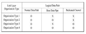
추출된 컨텍스트 정보는 특정 피지컬 데이터 경로를 통해 시그널링 데이터와 함께 RoHC 패킷 플로우와 별도로 전송될 수 있다. 컨텍스트의 전송은 피지컬 레이어 경로의 구성에 의존한다. 컨텍스트 정보는 시그널링 데이터 파이프를 통해 다른 링크 레이어 시그널링과 함께 전송될 수 있다.
즉, 컨텍스트 정보를 가지는 링크 레이어 패킷은 다른 링크 레이어 시그널링 정보를 가지는 링크 레이어 패킷들과 함께 시그널링 PLP 로 전송될 수 있다(Packet_Type = 100). 컨텍스트 정보가 추출된 압축 IP 패킷들은 일반적인 PLP 로 전송될 수 있다(Packet_Type = 001). 여기서 실시예에 따라, 시그널링 PLP 는 L1 시그널링 패쓰(path)를 의미할 수 있다. 또한 실시예에 따라 시그널링 PLP 는 일반적인 PLP 와 구분되지 않고, 시그널링 정보가 전송되는 특정한 일반 PLP 를 의미할 수도 있다.
수신측에서는, 패킷 스트림을 수신하기에 앞서, 수신기가 시그널링 정보를 얻어야 할 수 있다. 수신기가 시그널링 정보를 획득하기 위해 첫 PLP를 디코딩하면, 컨텍스트 시그널링도 수신될 수 있다. 시그널링 획득이 이루어진 후, 패킷 스트림을 수신하기 위한 PLP가 선택될 수 있다. 즉, 수신기는 먼저 이니셜 PLP 를 선택해 컨텍스트 정보를 비롯한 시그널링 정보를 얻을 수 있다. 여기서 이니셜 PLP 는 전술한 시그널링 PLP 일 수 있다. 이 후, 수신기는 패킷 스트림을 얻기 위한 PLP 를 선택할 수 있다. 이를 통하여 컨텍스트 정보는 패킷 스트림의 수신에 앞서 획득될 수 있다.
패킷 스트림을 얻기 위한 PLP 가 선택된 후, 어댑테이션 모듈은 수신된 패킷 플로우로부터 IRDYN 패킷을 검출할 수 있다. 그 후, 어댑테이션 모듈은 시그널링 데이터에서 컨텍스트 정보로부터 스태틱 체인을 파싱한다. 이는 IR 패킷을 수신하는 것과 유사하다. 동일한 컨텍스트 식별자에 대해, IRDYN 패킷은 IR 패킷으로 복구될 수 있다. 복구된 RoHC 패킷 플로우는 RoHC 디컴프레서로 보내질 수 있다. 이후 디컴프레션이 시작될 수 있다.
도 14 은 본 발명의 일 실시예에 따른 LMT(Link Mapping Table) 및 ROHCU 디스크립션 테이블을 도시한 도면이다.
이하, 링크 레이어 시그널링에 대해서 설명한다.
주로, 링크 레이어 시그널링은 IP 레벨 하에서 동작한다. 수신기 측에서, 링크 레이어 시그널링은 SLT 및 SLS와 같은 IP 레벨 시그널링보다 먼저 획득될 수 있다. 따라서 링크 레이어 시그널링은 세션 설정 이전에 획득될 수 있다.
링크 레이어 시그널링에 대해, 입력 경로에 따라 인터널 링크 레이어 시그널링 및 익스터널 링크 레이어 시그널링의 두 종류의 시그널링이 존재할 수 있다. 인터널 링크 레이어 시그널링은 송신기 측에서 링크 레이어에서 생성된다. 또한 링크 레이어는 외부 모듈 또는 프로토콜로부터 시그널링을 취한다. 이러한 종류의 시그널링 정보는 익스터널 링크 레이어 시그널링이라고 간주된다. 일부 시그널링이 IP 레벨 시그널링에 앞서 획득될 필요가 있으면, 외부 시그널링은 링크 레이어 패킷의 포맷으로 전송된다.
링크 레이어 시그널링은 전술한 바와 같이 링크 레이어 패킷으로 인캡슐레이션 될 수 있다. 링크 레이어 패킷은 바이너리 및 XML을 포함한 모든 포맷의 링크 레이어 시그널링을 전달할 수 있다. 동일한 시그널링 정보가 링크 레이어 시그널링에 대해 다른 포맷으로 전송될 수 있다.
인터널 링크 레이어 시그널링에는, 링크 매핑을 위한 시그널링 정보가 포함될 수 있다. LMT는 PLP에 전달되는 상위 레이어 세션의 리스트를 제공한다. LMT는 또한 링크 레이어에서 상위 레이어 세션을 전달하는 링크 레이어 패킷을 처리하기 위한 추가 정보를 제공한다.
본 발명에 따른 LMT 의 일 실시예(tsib14010)가 도시되었다.
signaling_type은 해당 테이블에 의해 전달되는 시그널링의 타입을 나타내는 8비트의 무부호 정수 필드일 수 있다. LMT에 대한 signaling_type 필드의 값은 0x01로 설정될 수 있다.
PLP_ID는 해당 테이블에 해당하는 PLP를 나타내는 8비트 필드일 수 있다.
num_session은 상기 PLP_ID 필드에 의해 식별되는 PLP에 전달되는 상위 레이어 세션의 개수를 제공하는 8비트의 무부호 정수 필드일 수 있다. signaling_type 필드의 값이 0x01이면, 해당 필드는 PLP에서 UDP/IP 세션의 개수를 나타낼 수 있다.
src_IP_add는 PLP_ID 필드에 의해 식별되는 PLP에 전달되는 상위 레이어 세션의 소스 IP 어드레스를 포함하는 32비트의 무부호 정수 필드일 수 있다.
dst_IP_add는 PLP_ID 필드에 의해 식별되는 PLP에 전달되는 상위 레이어 세션의 데스티네이션 IP 어드레스를 포함하는 32비트의 무부호 정수 필드일 수 있다.
src_UDP_port는 PLP_ID 필드에 의해 식별되는 PLP에 전달되는 상위 레이어 세션의 소스 UDP 포트 넘버를 나타내는 16비트의 무부호 정수 필드일 수 있다.
dst_UDP_port는 PLP_ID 필드에 의해 식별되는 PLP에 전달되는 상위 레이어 세션의 데스티네이션 UDP 포트 넘버를 나타내는 16비트의 무부호 정수 필드일 수 있다.
SID_flag는 상기 4개의 필드 Src_IP_add, Dst_IP_add, Src_UDP_Port, Dst_UDP_Port에 의해 식별되는 상위 레이어 세션을 전달하는 링크 레이어 패킷이 그 옵셔널 헤더에 SID 필드를 갖는지 여부를 나타내는 1비트의 부울 필드일 수 있다. 해당 필드의 값이 0으로 설정되면, 상위 레이어 세션을 전달하는 링크 레이어 패킷이 그 옵셔널 헤더에 SID 필드를 갖지 않을 수 있다. 해당 필드의 값이 1로 설정되면, 상위 레이어 세션을 전달하는 링크 레이어 패킷이 그 옵셔널 헤더에 SID 필드를 가질 수 있고, SID 필드의 값이 해당 테이블에서 다음 SID 필드와 동일할 수 있다.
compressed_flag는 헤더 컴프레션이 상기 4개의 필드 Src_IP_add, Dst_IP_add, Src_UDP_Port, Dst_UDP_Port에 의해 식별되는 상위 레이어 세션을 전달하는 링크 레이어 패킷에 적용되는지 여부를 나타내는 1비트 부울 필드일 수 있다. 해당 필드의 값이 0으로 설정되면, 상위 레이어 세션을 전달하는 링크 레이어 패킷은 그 베이스 헤더에 Packet_Type 필드의 0x00의 값을 가질 수 있다. 해당 필드의 값이 1로 설정되면, 상위 레이어 세션을 전달하는 링크 레이어 패킷은 그 베이스 헤더에 Packet_Type 필드의 0x01의 값을 가질 수 있고 Context_ID 필드가 존재할 수 있다.
SID는 상기 4개의 필드 Src_IP_add, Dst_IP_add, Src_UDP_Port, Dst_UDP_Port에 의해 식별되는 상위 레이어 세션을 전달하는 링크 레이어 패킷에 대한 서브 스트림 식별자를 나타내는 8비트의 무부호 정수 필드일 수 있다. 해당 필드는 SID_flag의 값이 1과 같을 때 존재할 수 있다.
context_id는 ROHCU 디스크립션 테이블에 제공된 CID(context id)에 대한 레퍼런스를 제공하는 8비트 필드일 수 있다. 해당 필드는 compressed_flag의 값이 1과 같을 때 존재할 수 있다.
본 발명에 따른 ROHCU 디스크립션 테이블의 일 실시예(tsib14020)가 도시되었다. 전술한 바와 같이 ROHCU 어댑테이션 모듈은 헤더 컴프레션에 관련된 정보들을 생성할 수 있다.
signaling_type은 해당 테이블에 의해 전달되는 시그널링의 타입을 나타내는 8비트 필드일 수 있다. ROHCU 디스크립션 테이블에 대한 signaling_type 필드의 값은 "0x02"로 설정될 수 있다.
PLP_ID는 해당 테이블에 해당하는 PLP를 나타내는 8비트 필드일 수 있다.
context_id는 압축된 IP 스트림의 CID를 나타내는 8비트 필드일 수 있다. 해당 시스템에서, 8비트의 CID는 큰 CID를 위해 사용될 수 있다.
context_profile은 스트림을 압축하기 위해 사용되는 프로토콜의 범위를 나타내는 8비트 필드일 수 있다. 해당 필드는 생략될 수 있다.
adaptation_mode는 해당 PLP에서 어댑테이션 모듈의 모드를 나타내는 2비트 필드일 수 있다. 어댑테이션 모드에 대해서는 전술하였다.
context_config는 컨텍스트 정보의 조합을 나타내는 2비트 필드일 수 있다. 해당 테이블에 컨텍스트 정보가 존재하지 않으면, 해당 필드는 '0x0'으로 설정될 수 있다. 해당 테이블에 static_chain() 또는 dynamic_chain() 바이트가 포함되면, 해당 필드는 '0x01' 또는 '0x02'로 설정될 수 있다. 해당 테이블에 static_chain() 및 dynamic_chain() 바이트가 모두 포함되면, 해당 필드는 '0x03'으로 설정될 수 있다.
context_length는 스태틱 체인 바이트 시퀀스의 길이를 나타내는 8비트 필드일 수 있다. 해당 필드는 생략될 수 있다.
static_chain_byte ()는 RoHCU 디컴프레서를 초기화하기 위해 사용되는 스태틱 정보를 전달하는 필드일 수 있다. 해당 필드의 크기 및 구조는 컨텍스트 프로파일에 의존한다.
dynamic_chain_byte ()는 RoHCU 디컴프레서를 초기화하기 위해 사용되는 다이네믹 정보를 전달하는 필드일 수 있다. 해당 필드의 크기 및 구조는 컨텍스트 프로파일에 의존한다.
static_chain_byte는 IR 패킷의 서브 헤더 정보로 정의될 수 있다. dynamic_chain_byte는 IR 패킷 및 IRDYN 패킷의 서브 헤더 정보로 정의될 수 있다.
도 15 은 본 발명의 일 실시예에 따른 송신기 측의 링크 레이어 구조를 도시한 도면이다.
본 실시예는 IP 패킷을 처리하는 것을 가정한 실시예이다. 송신기 측의 링크 레이어는 기능적인 관점에서 볼 때, 크게 시그널링 정보를 처리하는 링크 레이어 시그널링 부분, 오버헤드 리덕션 부분, 및/또는 인캡슐레이션 부분을 포함할 수 있다. 또한, 송신기 측의 링크 레이어는 링크 레이어 전체 동작에 대한 제어 및 스케쥴링을 위한 스케쥴러 및/또는 링크 레이어의 입,출력 부분 등을 포함할 수 있다.
먼저, 상위 레이어의 시그널링 정보 및/또는 시스템 파라미터(tsib15010)가 링크 레이어에 전달될 수 있다. 또한, IP 레이어(tsib15110)로부터 IP 패킷들을 포함하는 IP 스트림이 링크 레이어에 전달될 수 있다.
스케쥴러(tsib15020)는 전술한 바와 같이 링크 레이어에 포함된 여러 모듈들의 동작을 결정하고 제어하는 역할을 할 수 있다. 전달된 시그널링 정보 및/또는 시스템 파라미터(tsib15010) 는 스케쥴러(tsib15020)에 의해 필터링되거나 활용될 수 있다. 전달된 시그널링 정보 및/또는 시스템 파라미터(tsib15010) 중, 수신기에서 필요한 정보는 링크 레이어 시그널링 부분으로 전달될 수 있다. 또한 시그널링 정보 중 링크 레이어의 동작에 필요한 정보는 오버헤드 리덕션 컨트롤(tsib15120) 또는 인캡슐레이션 컨트롤(tsib15180)으로 전달될 수도 있다.
링크 레이어 시그널링 부분은, 피지컬 레이어에서 시그널링으로서 전송될 정보를 수집하고, 이를 전송에 적합한 형태로 변환/구성하는 역할을 수행할 수 있다. 링크 레이어 시그너널링 부분은 시그널링 매니저(tsib15030), 시그널링 포매터(tsib15040), 및/또는 채널을 위한 버퍼(tsib15050)을 포함할 수 있다.
시그널링 매니저(tsib15030)는 스케쥴러(tsib15020)으로부터 전달받은 시그널링 정보 및/또는 오버헤드 리덕션 부분으로부터 전달받은 시그널링 및/또는 컨텍스트(context) 정보를 입력받을 수 있다. 시그널링 매니저(tsib15030)는 전달받은 데이터들에 대하여, 각 시그널링 정보가 전송되어야할 경로를 결정할 수 있다. 각 시그널링 정보는 시그널링 매니저(tsib15030)에 의해 결정된 경로로 전달될 수 있다. 전술한 바와 같이 FIC, EAS 등의 구분된 채널로 전송될 시그널링 정보들은 시그널링 포매터(tsib15040)으로 전달될 수 있고, 그 밖의 시그널링 정보들은 인캡슐레이션 버퍼(tsib15070)으로 전달될 수 있다.
시그널링 포매터(tsib15040)는 별도로 구분된 채널을 통해 시그널링 정보가 전송될 수 있도록, 관련된 시그널링 정보를 각 구분된 채널에 맞는 형태로 포맷하는 역할을 할 수 있다. 전술한 바와 같이 피지컬 레이어에는 물리적/논리적으로 구분된 별도의 채널이 있을 수 있다. 이 구분된 채널들은 FIC 시그널링 정보나, EAS 관련 정보를 전송하는데 사용될 수 있다. FIC 또는 EAS 관련 정보는 시그널링 매니저(tsib15030)에 의해 분류되어 시그널링 포매터(tsib15040)로 입력될 수 있다. 시그널링 포매터(tsib15040)은 각 정보들을, 각자의 별도 채널에 맞게 포맷팅할 수 있다. FIC, EAS 이외에도, 피지컬 레이어가 특정 시그널링 정보를 별도의 구분된 채널을 통해 전송하는 것으로 설계된 경우에는, 그 특정 시그널링 정보를 위한 시그널링 포매터가 추가될 수 있다. 이러한 방식을 통하여, 링크 레이어가 다양한 피지컬 레이어에 대하여 호환가능해질 수 있다.
채널을 위한 버퍼(tsib15050)들은 시그널링 포매터(tsib15040)으로부터 전달받은 시그널링 정보들을, 지정된 별도의 채널(tsib15060)로 전달하는 역할을 할 수 있다. 별도의 채널들의 개수, 내용은 실시예에 따라 달라질 수 있다.
전술한 바와 같이, 시그널링 매니저(tsib15030)은 특정 채널로 전달되지 않는 시그널링 정보를 인캡슐레이션 버퍼(tsib15070)으로 전달할 수 있다. 인캡슐레이션 버퍼(tsib15070)는 특정 채널로 전달되지 않는 시그널링 정보를 전달받는 버퍼 역할을 할 수 있다.
시그널링 정보를 위한 인캡슐레이션(tsib15080)은 특정 채널로 전달되지 않는 시그널링 정보에 대하여 인캡슐레이션을 수행할 수 있다. 트랜스미션 버퍼(tsib15090)은 인캡슐레이션 된 시그널링 정보를, 시그널링 정보를 위한 DP(tsib15100) 로 전달하는 버퍼 역할을 할 수 있다. 여기서, 시그널링 정보를 위한 DP(tsib15100)은 전술한 PLS 영역을 의미할 수 있다.
오버헤드 리덕션 부분은 링크 레이어에 전달되는 패킷들의 오버헤드를 제거하여, 효율적인 전송이 가능하게 할 수 있다. 오버헤드 리덕션 부분은 링크 레이어에 입력되는 IP 스트림의 수만큼 구성될 수 있다.
오버헤드 리덕션 버퍼(tsib15130)는 상위 레이어로부터 전달된 IP 패킷을 입력받는 역할을 할 수 있다. 전달받은 IP 패킷은 오버헤드 리덕션 버퍼(tsib15130)를 통해 오버헤드 리덕션 부분으로 입력될 수 있다.
오버헤드 리덕션 컨트롤(tsib15120)은 오버헤드 리덕션 버퍼(tsib15130)로 입력되는 패킷 스트림에 대하여 오버헤드 리덕션을 수행할지 여부를 결정할 수 있다. 오버헤드 리덕션 컨트롤(tsib15120)은 패킷 스트림별로 오버헤드 리덕션 수행여부를 결정할 수 있다. 패킷 스트림에 오버헤드 리덕션이 수행되는 경우 RoHC 컴프레셔(tsib15140)으로 패킷들이 전달되어 오버헤드 리덕션이 수행될 수 있다. 패킷 스트림에 오버헤드 리덕션이 수행되지 않는 경우, 인캡슐레이션 부분으로 패킷들이 전달되어 오버헤드 리덕션 없이 인캡슐레이션이 진행될 수 있다. 패킷들의 오버헤드 리덕션 수행여부는 링크 레이어로 전달된 시그널링 정보들(tsib15010)에 의해 결정될 수 있다. 이 시그널링 정보들은 스케쥴러(tsib15020)에 의해 오버헤드 리덕션 컨트롤(tsib15180)으로 전달될 수 있다.
RoHC 컴프레셔(tsib15140) 은 패킷 스트림에 대하여 오버헤드 리덕션을 수행할 수 있다. RoHC 컴프레셔(tsib15140) 은 패킷들의 헤더를 압축하는 동작을 수행할 수 있다. 오버헤드 리덕션에는 다양한 방법들이 사용될 수 있다. 전술한, 본 발명이 제안한 방법들에 의하여 오버헤드 리덕션이 수행될 수 있다. 본 실시예는 IP 스트림을 가정했는 바, RoHC 컴프레셔라고 표현되었으나, 실시예에 따라 명칭은 변경될 수 있으며, 동작도 IP 스트림의 압축에 국한되지 아니하고, 모든 종류의 패킷들의 오버헤드 리덕션이 RoHC 컴프레셔(tsib15140)에 의해 수행될 수 있다.
패킷 스트림 컨피규레이션 블럭(tsib15150)은 헤더가 압축된 IP 패킷들 중에서, 시그널링 영역으로 전송될 정보와 패킷 스트림으로 전송될 정보를 분리할 수 있다. 패킷 스트림으로 전송될 정보란 DP 영역으로 전송될 정보를 의미할 수 있다. 시그널링 영역으로 전송될 정보는 시그널링 및/또는 컨텍스트 컨트롤(tsib15160)으로 전달될 수 있다. 패킷 스트림으로 전송될 정보는 인캡슐레이션 부분으로 전송될 수 있다.
시그널링 및/또는 컨텍스트 컨트롤(tsib15160)은 시그널링 및/또는 컨텍스트(context) 정보를 수집하고 이를 시그널링 매니저로 전달할 수 있다. 시그널링 및/또는 컨텍스트 정보를 시그널링 영역으로 전송하기 위함이다.
인캡슐레이션 부분은, 패킷들을 피지컬 레이어로 전달하기 적합한 형태로 인캡슐레이팅하는 동작을 수행할 수 있다. 인캡슐레이션 부분은 IP 스트림의 수만큼 구성될 수 있다.
인캡슐레이션 버퍼(tsib15170) 은 인캡슐레이션을 위해 패킷 스트림을 입력받는 역할을 할 수 있다. 오버헤드 리덕션이 수행된 경우 오버헤드 리덕션된 패킷들을, 오버헤드 리덕션이 수행되지 않은 경우 입력받은 IP 패킷 그대로를 입력받을 수 있다.
인캡슐레이션 컨트롤(tsib15180) 은 입력된 패킷 스트림에 대하여 인캡슐레이션을 수행할지 여부를 결정할 수 있다. 인캡슐레이션이 수행되는 경우 패킷 스트림은 세그멘테이션/컨케테네이션(tsib15190)으로 전달될 수 있다. 인캡슐레이션이 수행되지 않는 경우 패킷 스트림은 트랜스미션 버퍼(tsib15230)으로 전달될 수 있다. 패킷들의 인캡슐레이션의 수행여부는 링크 레이어로 전달된 시그널링 정보들(tsib15010)에 의해 결정될 수 있다. 이 시그널링 정보들은 스케쥴러(tsib15020)에 의해 인캡슐레이션 컨트롤(tsib15180)으로 전달될 수 있다.
세그멘테이션/컨케테네이션(tsib15190)에서는, 패킷들에 대하여 전술한 세그멘테이션 또는 컨케테네이션 작업이 수행될 수 있다. 즉, 입력된 IP 패킷이 링크 레이어의 출력인 링크 레이어 패킷보다 길 경우, 하나의 IP 패킷을 분할하여 여러 개의 세그멘트로 나누어 복수개의 링크 레이어 패킷 페이로드를 만들 수 있다. 또한, 입력된 IP 패킷이 링크 레이어의 출력인 링크 레이어 패킷보다 짧을 경우, 여러 개의 IP 패킷을 이어붙여 하나의 링크 레이어 패킷 페이로드를 만들 수 있다.
패킷 컨피규레이션 테이블(tsib15200)은, 세그멘테이션 및/또는 컨케테네이션된 링크 레이어 패킷의 구성 정보를 가질 수 있다. 패킷 컨피규레이션 테이블(tsib15200)의 정보는 송신기와 수신기가 같은 정보를 가질 수 있다. 패킷 컨피규레이션 테이블(tsib15200)의 정보가 송신기와 수신기에서 참조될 수 있다. 패킷 컨피규레이션 테이블(tsib15200)의 정보의 인덱스 값이 해당 링크 레이어 패킷의 헤더에 포함될 수 있다.
링크 레이어 헤더 정보 블락(tsib15210)은 인캡슐레이션 과정에서 발생하는 헤더 정보를 수집할 수 있다. 또한, 링크 레이어 헤더 정보 블락(tsib15210)은 패킷 컨피규레이션 테이블(tsib15200)이 가지는 정보를 수집할 수 있다. 링크 레이어 헤더 정보 블락(tsib15210)은 링크 레이어 패킷의 헤더 구조에 따라 헤더 정보를 구성할 수 있다.
헤더 어태치먼트(tsib15220)은 세그멘테이션 및/또는 컨케테네이션된 링크 레이어 패킷의 페이로드에 헤더를 추가할 수 있다. 트랜스미션 버퍼(tsib15230)은 링크 레이어 패킷을 피지컬 레이어의 DP(tsib15240) 로 전달하기 위한 버퍼 역할을 할 수 있다.
각 블락 내지 모듈 및 부분(part)들은 링크 레이어에서 하나의 모듈/프로토콜로서 구성될 수도 있고, 복수개의 모듈/프로토콜로 구성될 수도 있다.
도 16 는 본 발명의 일 실시예에 따른 수신기 측의 링크 레이어 구조를 도시한 도면이다.
본 실시예는 IP 패킷을 처리하는 것을 가정한 실시예이다. 수신기 측의 링크 레이어는 기능적인 관점에서 볼 때, 크게 시그널링 정보를 처리하는 링크 레이어 시그널링 부분, 오버헤드 프로세싱 부분, 및/또는 디캡슐레이션 부분을 포함할 수 있다. 또한, 수신기 측의 링크 레이어는 링크 레이어 전체 동작에 대한 제어 및 스케쥴링을 위한 스케쥴러 및/또는 링크 레이어의 입,출력 부분 등을 포함할 수 있다.
먼저, 피지컬 레이어를 통해 전송받은 각 정보들이 링크 레이어에 전달될 수 있다. 링크 레이어는 각 정보들을 처리하여, 송신측에서 처리하기 전의 원래 상태로 되돌린 뒤, 상위 레이어에 전달할 수 있다. 이 실시예에서 상위 레이어는 IP 레이어일 수 있다.
피지컬 레이어에서 구분된 특정 채널(tsib16030)들을 통해 전달된 정보들이 링크 레이어 시그널링 부분으로 전달될 수 있다. 링크 레이어 시그널링 부분은 피지컬 레이어로부터 수신된 시그널링 정보를 판별하고, 링크 레이어의 각 부분들로 판별된 시그널링 정보들을 전달하는 역할을 수행할 수 있다.
채널을 위한 버퍼(tsib16040)은 특정 채널들을 통해 전송된 시그널링 정보들을 전달받는 버퍼 역할을 할 수 있다. 전술한 바와 같이 피지컬 레이어에 물리적/논리적으로 구분된 별도의 채널이 존재할 경우, 그 채널들을 통해 전송된 시그널링 정보들을 전달받을 수 있다. 별도의 채널들로부터 받은 정보들이 분할된 상태일 경우, 완전한 형태의 정보가 될 때까지 분할된 정보들을 저장해 놓을 수 있다.
시그널링 디코더/파서(tsib16050)는 특정 채널을 통해 수신된 시그널링 정보의 포맷을 확인하고, 링크 레이어에서 활용될 정보들을 추출해 낼 수 있다. 특정 채널을 통한 시그널링 정보가 인코딩되어 있는 경우에는 디코딩을 수행할 수 있다. 또한, 실시예에 따라 해당 시그널링 정보의 무결성 등을 확인할 수 있다.
시그널링 매니저(tsib16060)은 여러 경로를 통해 수신된 시그널링 정보들을 통합할 수 있다. 후술할 시그널링을 위한 DP(tsib16070)을 통해 수신된 시그널링 정보들 역시 시그널링 매니저(tsib16060)에서 통합될 수 있다. 시그널링 매니저(tsib16060)은 링크 레이어 내의 각 부분에 필요한 시그널링 정보를 전달할 수 있다. 예를 들어 오버헤드 프로세싱 부분에, 패킷의 리커버리를 위한 컨텍스트 정보등을 전달할 수 있다. 또한, 스케쥴러(tsib16020)에 제어를 위한 시그널링 정보들을 전달해 줄 수 있다.
시그널링을 위한 DP(tsib16070)를 통해, 별도의 특별 채널로 수신되지 않은 일반적인 시그널링 정보들이 수신될 수 있다. 여기서, 시그널링을 위한 DP 란 PLS 또는 L1 등을 의미할 수 있다. 여기서 DP 는 PLP (Physical Layer Pipe) 라고 불릴 수도 있다. 리셉션 버퍼(tsib16080)은 시그널링을 위한 DP 로부터 수신된 시그널링 정보를 전달받는 버퍼 역할을 할 수 있다. 시그널링 정보의 디캡슐레이션(tsib16090)에서는 수신된 시그널링 정보가 디캡슐레이션될 수 있다. 디캡슐레이션 된 시그널링 정보는 디캡슐레이션 버퍼(tsib16100)을 거쳐 시그널링 매니저(tsib16060)으로 전달될 수 있다. 전술한 바와 같이, 시그널링 매니저(tsib16060)는 시그널링 정보를 취합하여 링크 레이어 내의 필요한 부분에 전달할 수 있다.
스케쥴러(tsib16020)은 링크 레이어에 포함된 여러 모듈들의 동작을 결정하고 제어하는 역할을 할 수 있다. 스케쥴러(tsib16020)은 리시버 정보(tsib16010) 및/또는 시그널링 매니저(tsib16060)으로부터 전달받은 정보를 이용하여, 링크 레이어의 각 부분을 제어할 수 있다. 또한, 스케쥴러(tsib16020)는 각 부분의 동작 모드등을 결정할 수 있다. 여기서, 리시버 정보(tsib16010) 는 수신기가 기 저장하고 있던 정보를 의미할 수 있다. 스케쥴러(tsib16020)는 채널 전환 등과 같이 사용자가 변경하는 정보 역시 이용하여 제어에 활용할 수 있다.
디캡슐레이션 부분은 피지컬 레이어의 DP(tsib16110)로부터 수신된 패킷을 필터링하고, 해당 패킷의 타입에 따라 패킷들을 분리해내는 역할을 수행할 수 있다. 디캡슐레이션 부분은 피지컬 레이어에서 동시에 디코딩할 수 있는 DP 의 수 만큼 구성될 수 있다.
디캡슐레이션 버퍼(tsib16110)은 디캡슐레이션을 위해 피지컬 레이어로부터 패킷 스트림을 입력받는 버퍼 역할을 할 수 있다. 디캡슐레이션 컨트롤(tsib16130)은 입력된 패킷 스트림에 대하여 디캡슐레이션을 수행할 것인지 여부를 결정할 수 있다. 디캡슐레이션이 수행될 경우 패킷 스트림은 링크 레이어 헤더 파서(tsib16140)으로 전달될 수 있다. 디캡슐레이션이 수행되지 않을 경우 패킷 스트림은 아웃풋 버퍼(tsib16220)로 전달될 수 있다. 디캡슐레이션의 수행여부를 결정하는 데에는 스케쥴러(tsib16020)으로부터 전달받은 시그널링 정보가 활용될 수 있다.
링크 레이어 헤더 파서(tsib16140)은 전달받은 링크 레이어 패킷의 헤더를 확인할 수 있다. 헤더를 확인함으로써, 링크 레이어 패킷의 페이로드에 포함되어 있는 IP 패킷의 구성을 확인할 수 있다. 예를 들어 IP 패킷은 세그멘테이션 되어 있거나, 컨케테네이션 되어 있을 수 있다.
패킷 컨피규레이션 테이블(tsib16150)은 세그멘테이션 및/또는 컨케테네이션으로 구성되는 링크 레이어 패킷의 페이로드 정보를 포함할 수 있다. 패킷 컨피규레이션 테이블(tsib16150)의 정보는 송신기와 수신기가 같은 정보를 가질 수 있다. 패킷 컨피규레이션 테이블(tsib16150)의 정보가 송신기와 수신기에서 참조될 수 있다. 링크 레이어 패킷에 포함된 인덱스 정보를 바탕으로 재결합(reassembly)에 필요한 값이 찾아질 수 있다.
재결합 블록(reassembly) (tsib16160)은 세그멘테이션 및/또는 컨케테네이션으로 구성된 링크 레이어 패킷의 페이로드를 원래의 IP 스트림의 패킷들로 구성할 수 있다. 세그멘트들을 하나로 모아 하나의 IP 패킷으로 재구성하거나, 컨케테네이션된 패킷들을 분리하여 복수개의 IP 패킷 스트림으로 재구성할 수 있다. 재결합된 IP 패킷들은 오버헤드 프로세싱 부분으로 전달될 수 있다.
오버헤드 프로세싱 부분은, 송신기에서 수행된 오버헤드 리덕션의 역과정으로, 오버헤드 리덕션된 패킷들을 원래의 패킷으로 돌리는 동작을 수행할 수 있다. 이 동작을 오버헤드 프로세싱이라 부를 수 있다. 오버헤드 프로세싱 부분은 피지컬 레이어에서 동시에 디코딩할 수 있는 DP 의 수 만큼 구성될 수 있다.
패킷 리커버리 버퍼(tsib16170)는 오버헤드 프로세싱을 수행하기 위해 디캡슐레이션된 RoHC 패킷 내지 IP 패킷을 입력받는 버퍼 역할을 할 수 있다.
오버헤드 컨트롤(tsib16180)은 디캡슐레이션된 패킷들에 대해 패킷 리커버리 및/또는 디컴프레션을 수행할 것인지 여부를 결정할 수 있다. 패킷 리커버리 및/또는 디컴프레션이 수행되는 경우 패킷 스트림 리커버리(tsib16190)으로 패킷이 전달될 수 있다. 패킷 리커버리 및/또는 디컴프레션이 수행되지 않는 경우, 패킷들은 아웃풋 버퍼(tsib16220)으로 전달될 수 있다. 패킷 리커버리 및/또는 디컴프레션의 수행 여부는 스케쥴러(tsib16020)에 의해 전달된 시그널링 정보에 근거해 결정될 수 있다.
패킷 스트림 리커버리(tsib16190)은 송신기에서 분리된 패킷 스트림과, 패킷 스트림의 컨텍스트 정보를 통합하는 동작을 수행할 수 있다. 이는 RoHC 디컴프레셔(tsib16210)에서 처리 가능하도록, 패킷 스트림을 복구하는 과정일 수 있다. 이 과정에서 시그널링 및/또는 컨텍스트 컨트롤(tsib16200)로부터 시그널링 정보 및/또는 컨텍스트 정보를 전달받을 수 있다. 시그널링 및/또는 컨텍스트 컨트롤(tsib16200)은 송신기로부터 전달된 시그널링 정보를 판별하고, 해당 컨텍스트 ID 에 맞는 스트림으로 매핑될 수 있도록 패킷 스트림 리버커리(tsib16190)에 시그널링 정보를 전달할 수 있다.
RoHC 디컴프레셔(tsib16210)은 패킷 스트림의 패킷들의 헤더를 복구할 수 있다. 패킷 스트림의 패킷들은 헤더가 복구되어 원래의 IP 패킷들의 형태로 복구될 수 있다. 즉, RoHC 디컴프레셔(tsib16210)은 오버헤드 프로세싱을 수행할 수 있다.
아웃풋 버퍼(tsib16220)은 IP 레이어(tsib16230)로 출력 스트림을 전달하기에 앞서, 버퍼 역할을 할 수 있다.
본 발명이 제안하는 송신기와 수신기의 링크 레이어는, 전술한 바와 같은 블록 내지 모듈들을 포함 가능하다. 이를 통해, 링크 레이어가 상위 레이어와 하위 레이어에 관계없이 독립적으로 동작할 수 있고, 오버헤드 리덕션을 효율적으로 수행할 수 있으며, 상하위 레이어 등에 따라 지원 가능한 기능의 확정/추가/제거가 용이해질 수 있다.
도 17 은 본 발명의 일 실시예에 따른, 링크 레이어를 통한 시그널링 전송 구조를 도시한 도면이다(송/수신측).
본 발명에서는 하나의 주파수 밴드 내에 복수개의 서비스 프로바이더(방송사)가 서비스를 제공할 수 있다. 또한 서비스 프로바이더는 복수개의 서비스들을 전송할 수 있는데, 하나의 서비스는 하나 이상의 컴포넌트를 포함할 수 있다. 사용자는 서비스 단위로 컨텐츠를 수신하는 것을 고려할 수 있다.
본 발명은 IP 하이브리드 방송을 지원하기 위하여, 복수개 세션 기반의 전송 프로토콜이 사용되는 것을 가정한다. 각 프로토콜의 전송 구조에 따라 그 시그널링 패쓰(path)로 전달되는 시그널링 정보가 결정될 수 있다. 각 프로토콜은 실시예에 따라 다양한 명칭이 부여될 수 있다.
도시된 송신측 데이터 구조(tsib17010) 에서, 서비스 프로바이더들(Broadcasters)은 복수개의 서비스(Service #1, #2, …) 를 제공할 수 있다. 일반적으로 서비스에 대한 시그널링은 일반적인 전송 세션을 통해 전송될 수 있으나(Signaling C), 실시예에 따라 특정 세션(dedicated session) 을 통해 전송될 수도 있다(Signaling B).
서비스 데이터 및 서비스 시그널링 정보들은 전송 프로토콜에 따라 인캡슐레이션 될 수 있다. 실시예에 따라 IP/UDP 가 사용될 수 있다. 실시예에 따라 IP/UDP 레이어에서의 시그널링(Signaling A) 가 추가될 수도 있다. 이 시그널링은 생략될 수 있다.
IP/UDP 로 처리된 데이터들은 링크 레이어로 입력될 수 있다. 링크 레이어에서는 전술한 바와 같이, 오버헤드 리덕션 및/또는 인캡슐레이션 과정을 수행할 수 있다. 여기서 링크 레이어 시그널링이 추가될 수 있다. 링크 레이어 시그널링에는 시스템 파라미터 등이 포함될 수 있다. 링크 레이어 시그널링에 대해서는 전술하였다.
이러한 처리를 거친 서비스 데이터 및 시그널링 정보들은, 피지컬 레이어에서 PLP 들을 통해 처리될 수 있다. 여기서 PLP 는 DP 로 불릴 수도 있다. 도시된 실시예에서는 Base DP/PLP 가 사용되는 경우를 상정하고 있으나, 실시예에 따라 Base DP/PLP 가 없이 일반적인 DP/PLP 만으로 전송이 수행될 수도 있다.
도시된 실시예에서는 FIC, EAC 등의 특정 채널(dedicated channel) 이 사용되고 있다. FIC를 통해 전달되는 시그널링을 FIT (Fast Information Table), EAC를 통해 전달되는 시그널링을 EAT (Emergency Alert Table)로 부를 수 있다. FIT 는 전술한 SLT 와 같을 수 있다. 이러한 특정 채널들은 실시예에 따라 사용되지 않을 수 있다. 특정 채널(Dedicated channel)이 구성되어 있지 않은 경우, FIT 와 EAT는 일반적인 링크 레이어 시그널링 전송 방법을 통해 전송되거나, 다른 서비스 데이터들처럼 IP/UDP 를 거쳐 PLP 로 전송될 수 있다.
실시예에 따라 시스템 파라미터에는 송신기 관련 파라미터, 서비스 프로바이더 관련 파라미터 등이 있을 수 있다. 링크 레이어 시그널링에는 IP 헤더 압축 관련 컨텍스트 정보 및/또는 해당 컨텍스트가 적용되는 데이터에 대한 식별정보가 포함될 수 있다. 상위 레이어의 시그널링에는 IP 주소, UDP 넘버, 서비스/컴포넌트 정보, 긴급 알림(Emergency alert) 관련 정보, 서비스 시그널링에 대한 IP/UDP 주소, 세션 ID 등등이 포함될 수 있다. 자세한 실시예에 대해서는 전술하였다.
도시된 수신측 데이터 구조(tsib17020) 에서, 수신기는 모든 PLP 를 디코딩할 필요 없이, 시그널링 정보를 활용하여 해당 서비스에 대한 PLP 만을 디코딩할 수 있다.
먼저, 사용자가 수신하고자 하는 서비스를 선택 하거나 변경 하면, 수신기는 해당 주파수로 튜닝 하고 해당 채널과 관련하여 DB 등에 저장하고 있는 수신기 정보를 읽어 들일 수 있다. 수신기의 DB 등에 저장되어 있는 정보는 최초 채널 스캔시 SLT 를 읽어 들여 구성 될 수 있다.
SLT 를 수신하고 해당 채널의 정보를 수신한 이후 기존에 저장되어 있던 DB를 업데이트하고, 사용자가 선택한 서비스의 전송 경로 및 컴포넌트 정보를 획득하거나 이러한 정보를 획득하는데 필요한 시그널링이 전송되는 경로에 대한 정보를 획득한다. SLT 의 버전 정보 등을 이용하여 해당 정보의 변경이 없다고 판단 되는 경우에는 디코딩 또는 파싱절차를 생략할 수 있다.
수신기는 해당 방송 스트림에서, PLP 의 피지컬 시그널링을 파싱하여 해당 PLP 내에 SLT 정보가 있는지 파악할 수 있다(도시되지 않음). 이는 피지컬 시그널링의 특정 필드를 통해 지시될 수 있다. SLT 정보에 접근하여 특정 서비스의 서비스 레이어 시그널링이 전송되는 위치에 접근할 수 있다. 이 서비스 레이어 시그널링은 IP/UDP 로 인캡슐레이션되어 전송 세션을 통해 전달될 수 있다. 이 서비스 레이어 시그널링을 이용하여 해당 서비스를 구성하는 컴포넌트에 대한 정보를 획득할 수 있다. 자세한 SLTSLS 구조는 전술한 바와 같다.
즉, SLT 를 이용하여 현재 채널에 전송되고 있는 여러 패킷 스트림 및 PLP 중, 해당 서비스의 수신에 필요한 상위 레이어 시그널링 정보(서비스 시그널링 정보)를 수신하기 위한 전송 경로 정보가 획득될 수 있다. 이 전송 경로 정보에는 IP 주소, UDP 포트 넘버, 세션 ID, PLP ID 등등이 포함될 수 있다. 여기서 실시예에 따라 IP/UDP 주소는 IANA 또는 시스템에서 미리 지정되어 있는 값을 사용할 수도 있다. 이러한 정보들은 DB 및 공유 메모리 접근 등의 방법으로 획득될 수도 있다.
링크 레이어 시그널링과 서비스 데이터가 동일한 PLP 를 통해 전송되거나 하나의 PLP 만이 운용되고 있는 경우, PLP 를 통해 전달되는 서비스 데이터는 링크 레이어 시그널링이 디코딩되는 동안 임시적으로 버퍼 등의 장치에 저장될 수 있다.
수신하고자 하는 서비스에 대한 서비스 시그널링 정보를 이용하여 해당 서비스가 실제로 전송되는 경로 정보를 획득할 수 있다. 또한 수신할 PLP 에 대한 오버헤드 리덕션 등의 정보를 이용하여, 수신되는 패킷 스트림에 대해 디캡슐레이션 및 헤더 리커버리가 수행될 수 있다.
도시된 실시예(tsib17020) 에서는, FIC, EAC 가 사용되었고, Base DP/PLP 개념이 상정되었다. 전술한 바와 같이 FIC, EAC, Base DP/PLP 개념은 활용되지 않을 수 있다.
이하에서는 설명의 편의를 위해 MISO 또는 MIMO 방식은 두 개의 안테나를 사용하지만, 본 발명은 두 개 이상의 안테나를 사용하는 시스템에 적용될 수 있다. 본 발명은 특정 용도에 요구되는 성능을 달성하면서 수신기 복잡도를 최소화하기 위해 최적화된 피지컬 프로파일 (또는 시스템)을 제안한다. 본 발명의 일 실시예에 따른 피지컬 프로파일(PHY profile) (베이스(base), 핸드헬드(handheld), 어드벤스(advanced) 프로파일)은 해당하는 수신기가 구현해야 하는 모든 구조의 서브셋으로, 대부분의 기능 블록을 공유하지만, 특정 블록 및/또는 파라미터에서는 약간 다르다. 시스템 발전을 위해, 퓨처 프로파일은 FEF (future extension frame)을 통해 단일 RF (radio frequency) 채널에 존재하는 프로파일과 멀티플렉싱 될 수도 있다. 본 발명의 일 실시예에 따른 베이스 프로파일 및 핸드헬드 프로파일은 MIMO가 적용되지 않는 프로파일을 의미하며, 어드밴스드 프로파일은 MIMO가 적용되는 프로파일을 의미한다. 베이스 프로파일은 지상파 방송 서비스 및 모바일 방송 서비스 모두에 대한 프로파일로 사용될 수 있다. 즉, 베이스 프로파일은 모바일 프로파일을 포함하는 프로파일의 개념을 정의하기 위해 사용될 수 있다. 또한, 어드벤스 프로파일은 MIMO을 갖는 베이스 프로파일에 대한 어드벤스 프로파일 및 MIMO을 갖는 핸드헬드 프로파일에 대한 어드벤스 프로파일로 구분될 수 있다. 그리고 본 발명의 프로파일은 설계자의 의도에 따라 변경될 수 있다.
다음의 용어 및 정의는 본 발명에 적용될 수 있다. 다음의 용어 및 정의는 설계에 따라 변경될 수 있다.
보조 스트림: 퓨처 익스텐션(future extension, 추후 확장) 또는 방송사나 네트워크 운영자에 의해 요구됨에 따라 사용될 수 있는 아직 정의되지 않은 변조 및 코딩의 데이터를 전달하는 셀의 시퀀스
베이스 데이터 파이프(base data pipe): 서비스 시그널링 데이터를 전달하는 데이터 파이프
베이스밴드 프레임 (또는 BBFRAME): 하나의 FEC 인코딩 과정 (BCH 및 LDPC 인코딩)에 대한 입력을 형성하는 Kbch 비트의 집합
셀(cell): OFDM 전송의 하나의 캐리어에 의해 전달되는 변조값
코딩 블록(coded block): PLS1 데이터의 LDPC 인코딩된 블록 또는 PLS2 데이터의 LDPC 인코딩된 블록들 중 하나
데이터 파이프(data pipe): 하나 또는 다수의 서비스 또는 서비스 컴포넌트를 전달할 수 있는 서비스 데이터 또는 관련된 메타데이터를 전달하는 물리 계층(physical layer)에서의 로지컬 채널
데이터 파이프 유닛(DPU, data pipe unit): 데이터 셀을 프레임에서의 데이터 파이프에 할당할 수 있는 기본 유닛
데이터 심볼(data symbol): 프리앰블 심볼이 아닌 프레임에서의 OFDM 심볼 (프레임 시그널링 심볼 및 프레임 엣지(edge) 심볼은 데이터 심볼에 포함된다.)
DP_ID: 해당 8비트 필드는 SYSTEM_ID에 의해 식별된 시스템 내에서 데이터 파이프를 유일하게 식별한다.
더미 셀(dummy cell): PLS (physical layer signalling) 시그널링, 데이터 파이프, 또는 보조 스트림을 위해 사용되지 않은 남아 있는 용량을 채우는 데 사용되는 의사 랜덤값을 전달하는 셀
EAC (emergency alert channel, 비상 경보 채널): EAS 정보 데이터를 전달하는 프레임 중 일부
프레임(frame): 프리앰블로 시작해서 프레임 엣지 심볼로 종료되는 물리 계층(physical layer) 타임 슬롯
프레임 리피티션 유닛(frame repetition unit, 프레임 반복 단위): 슈퍼 프레임(superframe)에서 8회 반복되는 FEF를 포함하는 동일한 또는 다른 피지컬 프로파일에 속하는 프레임의 집합
FIC (fast information channel, 고속 정보 채널): 서비스와 해당 베이스 데이터 파이프 사이에서의 매핑 정보를 전달하는 프레임에서 로지컬 채널
FECBLOCK: 데이터 파이프 데이터의 LDPC 인코딩된 비트의 집합
FFT 사이즈: 기본 주기 T의 사이클로 표현된 액티브 심볼 주기 Ts와 동일한 특정 모드에 사용되는 명목상의 FFT 사이즈
프레임 시그널링 심볼(frame signaling symbol): PLS 데이터의 일부를 전달하는, FFT 사이즈, 가드 인터벌(guard interval), 및 스캐터(scattered) 파일럿 패턴의 특정 조합에서 프레임의 시작에서 사용되는 더 높은 파일럿 밀도를 갖는 OFDM 심볼
프레임 엣지 심볼(frame edge symbol): FFT 사이즈, 가드 인터벌, 및 스캐터 파일럿 패턴의 특정 조합에서 프레임의 끝에서 사용되는 더 높은 파일럿 밀도를 갖는 OFDM 심볼
프레임 그룹(framegroup): 슈퍼 프레임에서 동일한 피지컬 프로파일 타입을 갖는 모든 프레임의 집합
퓨쳐 익스텐션 프레임(future extention frame, 추후 확장 프레임): 프리앰블로 시작하는, 추후 확장에 사용될 수 있는 슈퍼 프레임 내에서 물리 계층(physical layer) 타임 슬롯
퓨처캐스트(futurecast) UTB 시스템: 입력이 하나 이상의 MPEG2TS 또는 IP (Internet protocol) 또는 일반 스트림이고 출력이 RF 시그널인 제안된 물리 계층(physical layer) 방송 시스템
인풋 스트림(input stream, 입력 스트림): 시스템에 의해 최종 사용자에게 전달되는 서비스의 조화(ensemble)를 위한 데이터의 스트림
노멀(normal) 데이터 심볼: 프레임 시그널링 심볼 및 프레임 엣지 심볼을 제외한 데이터 심볼
피지컬 프로파일(PHY profile): 해당하는 수신기가 구현해야 하는 모든 구조의 서브셋
PLS: PLS1 및 PLS2로 구성된 물리 계층(physical layer) 시그널링 데이터
PLS1: PLS2를 디코딩하는 데 필요한 파라미터뿐만 아니라 시스템에 관한 기본 정보를 전달하는 고정된 사이즈, 코딩, 변조를 갖는 FSS (frame signalling symbol)로 전달되는 PLS 데이터의 첫 번째 집합
NOTE: PLS1 데이터는 프레임 그룹의 듀레이션(duration) 동안 일정하다.
PLS2: 데이터 파이프 및 시스템에 관한 더욱 상세한 PLS 데이터를 전달하는 FSS로 전송되는 PLS 데이터의 두 번째 집합
PLS2 다이나믹(dynamic, 동적) 데이터: 프레임마다 다이나믹(dynamic, 동적)으로 변화하는 PLS2 데이터
PLS2 스태틱(static, 정적) 데이터: 프레임 그룹의 듀레이션 동안 스태틱(static, 정적)인 PLS2 데이터
프리앰블 시그널링 데이터(preamble signaling data): 프리앰블 심볼에 의해 전달되고 시스템의 기본 모드를 확인하는 데 사용되는 시그널링 데이터
프리앰블 심볼(preamble symbol): 기본 PLS 데이터를 전달하고 프레임의 시작에 위치하는 고정된 길이의 파일럿 심볼
프리앰블 심볼은 시스템 신호, 그 타이밍, 주파수 오프셋, 및 FFT 사이즈를 검출하기 위해 고속 초기 밴드 스캔에 주로 사용된다.
추후 사용(future use)을 위해 리저브드(reserved): 현재 문서에서 정의되지 않지만 추후에 정의될 수 있음
슈퍼 프레임(superframe): 8개의 프레임 반복 단위의 집합
타임 인터리빙 블록(time interleaving block, TI block): 타임 인터리버 메모리의 하나의 용도에 해당하는, 타임 인터리빙이 실행되는 셀의 집합
타임 인터리빙 그룹(time interleaving group, TI group): 정수, 다이나믹(dynamic, 동적)으로 변화하는 XFECBLOCK의 수로 이루어진, 특정 데이터 파이프에 대한 다이나믹(dynamic, 동적) 용량 할당이 실행되는 단위
NOTE: 타임 인터리빙 그룹은 하나의 프레임에 직접 매핑되거나 다수의 프레임에 매핑될 수 있다. 타임 인터리빙 그룹은 하나 이상의 타임 인터리빙 블록을 포함할 수 있다.
타입 1 데이터 파이프(Type 1 DP): 모든 데이터 파이프가 프레임에 TDM (time division multiplexing) 방식으로 매핑되는 프레임의 데이터 파이프
타입 2 데이터 파이프(Type 2 DP): 모든 데이터 파이프가 프레임에 FDM 방식으로 매핑되는 프레임의 데이터 파이프
XFECBLOCK: 하나의 LDPC FECBLOCK의 모든 비트를 전달하는 Ncells 셀들의 집합
도 18은 본 발명의 일 실시예에 따른 차세대 방송 서비스에 대한 방송 신호 송신 장치의 구조를 나타낸다.
본 발명의 일 실시예에 따른 차세대 방송 서비스에 대한 방송 신호 송신 장치는 인풋 포맷 블록 (Input Format block) (1000), BICM (bit interleaved coding & modulation) 블록(1010), 프레임 빌딩 블록 (Frame building block) (1020), OFDM (orthogonal frequency division multiplexing) 제너레이션 블록 (OFDM generation block)(1030), 및 시그널링 생성 블록(1040)을 포함할 수 있다. 방송 신호 송신 장치의 각 블록의 동작에 대해 설명한다.
본 발명의 일 실시예에 따른 입력 데이터는 IP 스트림/패킷 및 MPEG2TS이 주요 입력 포맷이 될 수 있으며, 다른 스트림 타입은 일반 스트림으로 다루어진다. 이들 데이터 입력에 추가로, 관리 정보가 입력되어 각 입력 스트림에 대한 해당 대역폭의 스케줄링 및 할당을 제어한다. 또한 본 발명에서는 하나 또는 다수의 TS 스트림, IP 스트림 및/또는 일반 스트림 입력이 동시에 허용된다.
인풋 포맷 블록(1000)은 각각의 입력 스트림을 독립적인 코딩 및 변조가 적용되는 하나 또는 다수의 데이터 파이프로 디멀티플렉싱 할 수 있다. 데이터 파이프는 견고성(robustness) 제어를 위한 기본 단위이며, 이는 QoS (Quality of Service)에 영향을 미친다. 하나 또는 다수의 서비스 또는 서비스 컴포넌트가 하나의 데이터 파이프에 의해 전달될 수 있다. 데이터 파이프는 하나 또는 다수의 서비스 또는 서비스 컴포넌트를 전달할 수 있는 서비스 데이터 또는 관련 메타데이터를 전달하는 물리 계층(physical layer)에서의 로지컬 채널이다.
또한, 데이터 파이프 유닛은 하나의 프레임에서 데이터 셀을 데이터 파이프에 할당하기 위한 기본 유닛이다.
물리 계층(physical layer)으로의 입력은 하나 또는 다수의 데이터 스트림으로 구성될 수 있다. 각각의 데이터 스트림은 하나의 데이터 파이프에 의해 전달된다. 인풋 포맷 블록(1000)은 하나 또는 그 이상의 물리적 경로 (physical path 또는 DP)를 통해 입력되는 데이터 스트림을 BBF (baseband frame)으로 변환할 수 있다. 이 경우 인풋 포맷 블록(1000)은 입력 데이터 (TS 또는 IP 입력 스트림)들에 대해 전송 효율을 증가시키기 위해 널 패킷 딜리션 (null packet deletion) 또는 헤더 컴프레션 (header compression)을 수행할 수 있다. 수신기는 헤더의 특정 부분에 대한 선험적인(a priori) 정보를 가질 수 있기 때문에, 이 알려진 정보(known information)는 송신기에서 삭제될 수 있다. 널 패킷 딜리션 블록(3030)은 TS 입력 스트림 경우에만 사용될 수 있다.
BICM 블록(1010)에서, 패리티(parity) 데이터는 에러 정정을 위해 추가되고, 인코딩된 비트 스트림은 복소수값 컨스텔레이션 심볼에 매핑된다. 해당 심볼은 해당 데이터 파이프에 사용되는 특정 인터리빙 깊이에 걸쳐 인터리빙 된다. 어드벤스 프로파일에 있어서, BICM 블록(1010)에서 MIMO 인코딩이 실행되고 추가 데이터 경로가 MIMO 전송을 위해 출력에 추가된다.
프레임 빌딩 블록(1020)은 하나의 프레임 내에서 입력 데이터 파이프의 데이터 셀을 OFDM 심볼로 매핑하고 주파수 영역 다이버시티를 위해, 특히 주파수 선택적 페이딩 채널을 방지하기 위해 주파수 인터리빙을 수행할 수 있다. 프레임 빌딩 블록은 딜레이 컴펜세이션(delay compensation, 지연보상) 블록, 셀 매퍼 (cell mapper) 및 프리퀀시 인터리버 (frequency interleaver)를 포함할 수 있다.
딜레이 컴펜세이션(delay compensation, 지연보상) 블록은 데이터 파이프와 해당하는 PLS 데이터 사이의 타이밍을 조절하여 송신기 측에서 데이터 파이프와 해당하는 PLS 데이터 간의 동시성(cotime)을 보장할 수 있다. 인풋 포맷 블록 및 BICM 블록으로 인한 데이터 파이프의 지연을 다룸으로써 PLS 데이터는 데이터 파이프만큼 지연된다. BICM 블록의 지연은 주로 타임 인터리버로 인한 것이다. 인 밴드(Inband) 시그널링 데이터는 다음 타임 인터리빙 그룹의 정보를 시그널링될 데이터 파이프보다 하나의 프레임 앞서 전달되도록 할 수 있다. 딜레이 컴펜세이션(delay compensation, 지연보상) 블록은 그에 맞추어 인 밴드(Inband) 시그널링 데이터를 지연시킨다.
셀 매퍼는 PLS, 데이터 파이프, 보조 스트림, 및 더미 셀 등을 프레임 내에서 OFDM 심볼의 액티브(active) 캐리어에 매핑할 수 있다. 셀 매퍼의 기본 기능은 각각의 데이터 파이프, PLS 셀에 대한 타임 인터리빙에 의해 생성된 데이터 셀을, 존재하면, 하나의 프레임 내에서 각각의 OFDM 심볼에 해당하는 액티브(active) OFDM 셀의 어레이에 매핑하는 것이다. (PSI(program specific information)/SI와 같은) 서비스 시그널링 데이터는 개별적으로 수집되어 데이터 파이프에 의해 보내질 수 있다. 셀 매퍼는 프레임 구조의 구성 및 스케줄러에 의해 생성된 다이나믹 인포메이션(dynamic information, 동적 정보)에 따라 동작한다. 프리퀀시 인터리버는 셀 매퍼로부터 의해 수신된 데이터 셀을 랜덤하게 인터리빙하여 주파수 다이버시티를 제공할 수 있다. 또한, 프리퀀시 인터리버는 단일 프레임에서 최대의 인터리빙 이득을 얻기 위해 다른 인터리빙 시드(seed) 순서를 이용하여 두 개의 순차적인 OFDM 심볼로 구성된 OFDM 심볼 페어(pair, 쌍)에서 동작할 수 있다.
OFDM 제너레이션 블록(1030)은 프레임 빌딩 블록에 의해 생성된 셀에 의해 OFDM 캐리어를 변조하고, 파일럿을 삽입하고, 전송을 위한 시간 영역 신호를 생성한다. 또한, 해당 블록은 순차적으로 가드 인터벌을 삽입하고, PAPR 감소 처리를 적용하여 최종 RF 신호를 생성한다.
구체적으로, 프리앰블을 각 프레임의 시작에 삽입한 후, OFDM 제너레이션 블록(1030)은 사이클릭 프리픽스(cyclic prefix)을 가드 인터벌로 갖는 기존의 OFDM 변조를 적용할 수 있다. 안테나 스페이스 다이버시티를 위해, 분산된(distributed) MISO 방식이 송신기에 걸쳐 적용된다. 또한, PAPR (peaktoaverage power ratio) 방식이 시간 영역에서 실행된다. 유연한 네트워크 방식을 위해, 본 발명은 다양한 FFT 사이즈, 가드 인터벌 길이, 해당 파일럿 패턴의 집합을 제공한다.
또한 본 발명은 방송 서비스를 제공하는 둘 이상의 서로 다른 방송 송신/수신 시스템의 데이터가 동일한 RF 신호 대역에서 동시에 전송될 수 있도록 시간 영역에서 복수의 방송 송신/수신 시스템의 신호를 멀티플렉싱 할 수 있다. 이 경우, 둘 이상의 서로 다른 방송 송신/수신 시스템은 서로 다른 방송 서비스를 제공하는 시스템을 말한다. 서로 다른 방송 서비스는 지상파 방송 서비스, 모바일 방송 서비스 등을 의미할 수 있다.
시그널링 생성 블록(1040)은 각 기능 블록의 동작에 사용되는 물리 계층(physical layer) 시그널링 정보를 생성할 수 있다. 해당 시그널링 정보는 또한 관심 있는 서비스가 수신기 측에서 적절히 복구되도록 전송된다. 본 발명의 일실시예에 따른 시그널링 정보는 PLS 데이터를 포함할 수 있다. PLS는 수신기에서 피지컬 레이어(physical layer) 데이터 파이프에 접속할 수 있는 수단을 제공한다. PLS 데이터는 PLS1 데이터 및 PLS2 데이터로 구성된다.
PLS1 데이터는 PLS2 데이터를 디코딩하는 데 필요한 파라미터뿐만 아니라 시스템에 관한 기본 정보를 전달하는 고정된 사이즈, 코딩, 변조를 갖는 프레임에서 FSS로 전달되는 PLS 데이터의 첫 번째 집합이다. PLS1 데이터는 PLS2 데이터의 수신 및 디코딩을 가능하게 하는 데 요구되는 파라미터를 포함하는 기본 송신 파라미터를 제공한다. 또한, PLS1 데이터는 프레임 그룹의 듀레이션 동안 일정하다.
PLS2 데이터는 데이터 파이프 및 시스템에 관한 더욱 상세한 PLS 데이터를 전달하는 FSS로 전송되는 PLS 데이터의 두 번째 집합이다. PLS2는 수신기가 원하는 데이터 파이프를 디코딩하는 데 충분한 정보를 제공하는 파라미터를 포함한다. PLS2 시그널링은 PLS2 스태틱(static, 정적) 데이터(PLS2STAT 데이터) 및 PLS2 다이나믹(dynamic, 동적) 데이터(PLS2DYN 데이터)의 두 종류의 파라미터로 더 구성된다. PLS2 스태틱(static, 정적) 데이터는 프레임 그룹의 듀레이션 동안 스태틱(static, 정적)인 PLS2 데이터이고, PLS2 다이나믹(dynamic, 동적) 데이터는 프레임마다 다이나믹(dynamic, 동적)으로 변화하는 PLS2 데이터이다. PLS 데이터에 대한 자세한 내용은 후술한다.
전술한 블록은 생략될 수도 있고 유사 또는 동일 기능을 갖는 블록에 의해 대체될 수도 있다.
도 19는 본 발명의 일 실시예에 따른 BICM 블록을 나타낸다.
도 19에 도시된 BICM 블록은 도 18을 참조하여 설명한 BICM 블록(1010)의 일 실시예에 해당한다.
전술한 바와 같이, 본 발명의 일 실시예에 따른 차세대 방송 서비스에 대한 방송 신호 송신 장치는 지상파 방송 서비스, 모바일 방송 서비스, UHDTV 서비스 등을 제공할 수 있다.
QoS가 본 발명의 일 실시예에 따른 차세대 방송 서비스에 대한 방송 신호 송신 장치에 의해 제공되는 서비스의 특성에 의존하므로, 각각의 서비스에 해당하는 데이터는 서로 다른 방식을 통해 처리되어야 한다. 따라서, 본 발명의 일 실시예에 따른 BICM 블록은 SISO, MISO, MIMO 방식을 각각의 데이터 경로에 해당하는 데이터 파이프에 독립적으로 적용함으로써 각데이터 파이프를 독립적으로 처리할 수 있다. 결과적으로, 본 발명의 일 실시예에 따른 차세대 방송 서비스에 대한 방송 신호 송신 장치는 각각의 데이터 파이프를 통해 전송되는 각 서비스 또는 서비스 컴포넌트에 대한 QoS를 조절할 수 있다.
(a)는 MIMO가 적용되지 않는 프로파일 (또는 시스템)에 적용되는 BICM 블록을 나타내고, (b)는 MIMO가 적용되는 프로파일(또는 시스템)의 BICM 블록을 나타낸다.
MIMO가 적용되지 않는 BICM 블록 및 MIMO가 적용되는 BICM 블록은 각각의 데이터 파이프를 처리하기 위한 복수의 처리 블록을 포함할 수 있다.
MIMO가 적용되지 않는 BICM 블록 및 MIMO가 적용되는 BICM 블록의 각각의 처리 블록에 대해 설명한다.
MIMO가 적용되지 않는 BICM 블록의 처리 블록(5000)은 데이터 FEC 인코더(5010), 비트 인터리버(5020), 컨스텔레이션 매퍼(mapper)(5030), SSD (signal space diversity) 인코딩 블록(5040), 타임 인터리버(5050)를 포함할 수 있다.
데이터 FEC 인코더(5010)는 외부 코딩(BCH) 및 내부 코딩(LDPC)을 이용하여 FECBLOCK 절차를 생성하기 위해 입력 BBF에 FEC 인코딩을 실행한다. 외부 코딩(BCH)은 선택적인 코딩 방법이다. 데이터 FEC 인코더(5010)의 구체적인 동작에 대해서는 후술한다.
비트 인터리버(5020)는 효율적으로 실현 가능한 구조를 제공하면서 데이터 FEC 인코더(5010)의 출력을 인터리빙하여 LDPC 코드 및 변조 방식의 조합으로 최적화된 성능을 달성할 수 있다. 비트 인터리버(5020)의 구체적인 동작에 대해서는 후술한다.
컨스텔레이션 매퍼(5030)는 QPSK, QAM16, 불균일 QAM (NUQ64, NUQ256, NUQ1024) 또는 불균일 컨스텔레이션 (NUC16, NUC64, NUC256, NUC1024)을 이용해서 베이스 및 핸드헬드 프로파일에서 비트 인터리버(5020)로부터의 각각의 셀 워드를 변조하거나 어드벤스 프로파일에서 셀 워드 디멀티플렉서(50101)로부터의 셀 워드를 변조하여 파워가 정규화된 컨스텔레이션 포인트 el을 제공할 수 있다. 해당 컨스텔레이션 매핑은 데이터 파이프에 대해서만 적용된다. NUQ가 임의의 형태를 갖는 반면, QAM16 및 NUQ는 정사각형 모양을 갖는 것이 관찰된다. 각각의 컨스텔레이션이 90도의 배수만큼 회전되면, 회전된 컨스텔레이션은 원래의 것과 정확히 겹쳐진다. 회전 대칭 특성으로 인해 실수 및 허수 컴포넌트의 용량 및 평균 파워가 서로 동일해진다. NUQ 및 NUC는 모두 각 코드 레이트(code rate)에 대해 특별히 정의되고, 사용되는 특정 하나는 PLS2 데이터에 보관된 파라미터 DP_MOD에 의해 시그널링 된다.
타임 인터리버(5050)는 데이터 파이프 레벨에서 동작할 수 있다. 타임 인터리빙의 파라미터는 각각의 데이터 파이프에 대해 다르게 설정될 수 있다. 타임 인터리버(5050)의 구체적인 동작에 관해서는 후술한다.
MIMO가 적용되는 BICM 블록의 처리 블록(50001)은 데이터 FEC 인코더, 비트 인터리버, 컨스텔레이션 매퍼, 및 타임 인터리버를 포함할 수 있다.
단, 처리 블록(50001)은 셀 워드 디멀티플렉서(50101) 및 MIMO 인코딩 블록(50201)을 더 포함한다는 점에서 MIMO가 적용되지 않는 BICM의 처리 블록(5000)과 구별된다.
또한, 처리 블록(50001)에서의 데이터 FEC 인코더, 비트 인터리버, 컨스텔레이션 매퍼, 타임 인터리버의 동작은 전술한 데이터 FEC 인코더(5010), 비트 인터리버(5020), 컨스텔레이션 매퍼(5030), 타임 인터리버(5050)의 동작에 해당하므로, 그 설명은 생략한다.
셀 워드 디멀티플렉서(50101)는 어드벤스 프로파일의 데이터 파이프가 MIMO 처리를 위해 단일 셀 워드 스트림을 이중 셀 워드 스트림으로 분리하는 데 사용된다.
MIMO 인코딩 블록(50201)은 MIMO 인코딩 방식을 이용해서 셀 워드 디멀티플렉서(50101)의 출력을 처리할 수 있다. MIMO 인코딩 방식은 방송 신호 송신을 위해 최적화되었다. MIMO 기술은 용량 증가를 얻기 위한 유망한 방식이지만, 채널 특성에 의존한다. 특별히 방송에 대해서, 서로 다른 신호 전파 특성으로 인한 두 안테나 사이의 수신 신호 파워 차이 또는 채널의 강한 LOS 컴포넌트는 MIMO로부터 용량 이득을 얻는 것을 어렵게 한다. 제안된 MIMO 인코딩 방식은 MIMO 출력 신호 중 하나의 위상 랜덤화 및 회전 기반 프리코딩을 이용하여 이 문제를 극복한다.
MIMO 인코딩은 송신기 및 수신기 모두에서 적어도 두 개의 안테나를 필요로 하는 2x2 MIMO 시스템을 위해 의도된다. 본 발명의 MIMO 인코딩 모드는 FRSM (fullrate spatial multiplexing)으로 정의 될 수 있다. FRSM 인코딩은 수신기 측에서의 비교적 작은 복잡도 증가로 용량 증가를 제공할 수 있다. 또한 본 발명의 MIMO 인코딩 방식은 안테나 극성 배치를 제한하지 않는다.
MIMO 처리는 데이터 파이프 레벨에서 적용된다. 컨스텔레이션 매퍼 출력의 페어(pair, 쌍)인 NUQ (e1,i 및 e2,i)는 MIMO 인코더의 입력으로 공급된다. MIMO 인코더 출력 페어(pair, 쌍)(g1,i 및 g2,i)은 각각의 송신 안테나의 동일한 캐리어 k 및 OFDM 심볼 l에 의해 전송된다.
전술한 블록은 생략되거나 유사 또는 동일 기능을 갖는 블록으로 대체될 수 있다.
도 20는 본 발명의 다른 실시예에 따른 BICM 블록을 나타낸다.
도 20에 도시된 BICM 블록은 도 18을 참조하여 설명한 BICM 블록(1010)의 일 실시예에 해당한다.
도 20은 PLS, EAC, 및 FIC의 보호를 위한 BICM 블록을 나타낸다. EAC는 EAS 정보 데이터를 전달하는 프레임의 일부이고, FIC는 서비스와 해당하는 베이스 데이터 파이프 사이에서 매핑 정보를 전달하는 프레임에서의 로지컬 채널이다. EAC 및 FIC에 대한 상세한 설명은 후술한다.
도 20을 참조하면, PLS, EAC, 및 FIC의 보호를 위한 BICM 블록은 PLS FEC 인코더(6000), 비트 인터리버(6010), 및 컨스텔레이션 매퍼(6020)를 포함할 수 있다.
또한, PLS FEC 인코더(6000)는 스크램블러, BCH 인코딩/제로 삽입 블록, LDPC 인코딩 블록, 및 LDPC 패리티 펑처링(puncturing) 블록을 포함할 수 있다. BICM 블록의 각 블록에 대해 설명한다.
PLS FEC 인코더(6000)는 스크램블링된 PLS 1/2 데이터, EAC 및 FIC 섹션을 인코딩할 수 있다.
스크램블러는 BCH 인코딩 및 쇼트닝(shortening) 및 펑처링된 LDPC 인코딩 전에 PLS1 데이터 및 PLS2 데이터를 스크램블링 할 수 있다.
BCH 인코딩/제로 삽입 블록은 PLS 보호를 위한 쇼트닝된 BCH 코드를 이용하여 스크램블링된 PLS 1/2 데이터에 외부 인코딩을 수행하고, BCH 인코딩 후에 제로 비트를 삽입할 수 있다. PLS1 데이터에 대해서만, 제로 삽입의 출력 비트가 LDPC 인코딩 전에 퍼뮤테이션(permutation) 될 수 있다.
LDPC 인코딩 블록은 LDPC 코드를 이용하여 BCH 인코딩/제로 삽입 블록의 출력을 인코딩할 수 있다. 완전한 코딩 블록을 생성하기 위해, Cldpc 및 패리티 비트 Pldpc는 각각의 제로가 삽입된 PLS 정보 블록 Ildpc로부터 조직적으로 인코딩되고, 그 뒤에 첨부된다.
LDPC 패리티 펑처링 블록은 PLS1 데이터 및 PLS2 데이터에 대해 펑처링을 수행할 수 있다.
쇼트닝이 PLS1 데이터 보호에 적용되면, 일부 LDPC 패리티 비트는 LDPC 인코딩 후에 펑처링된다. 또한, PLS2 데이터 보호를 위해, PLS2의 LDPC 패리티 비트가 LDPC 인코딩 후에 펑처링된다. 이들 펑처링된 비트는 전송되지 않는다.
비트 인터리버(6010)는 각각의 쇼트닝 및 펑처링된 PLS1 데이터 및 PLS2 데이터를 인터리빙할 수 있다.
컨스텔레이션 매퍼(6020)는 비트 인터리빙된 PLS1 데이터 및 PLS2 데이터를 컨스텔레이션에 매핑할 수 있다.
전술한 블록은 생략되거나 유사 또는 동일 기능을 갖는 블록으로 대체될 수 있다.
도 21는 본 발명의 일 실시예에 따른 PLS의 비트 인터리빙을 과정을 나타낸 도면이다.
각각의 쇼트닝 및 펑처링된 PLS1 및 PLS2 코딩 블록은 도 22에 도시된 바와 같이 1비트씩 인터리빙 된다. 추가 패리티 비트의 각 블록은 동일한 블록 인터리빙 구조로 인터리빙 되지만 별도로 인터리빙 된다.
BPSK의 경우, 실수 및 허수 부분에서 FEC 코딩 비트를 복제하기 위해 비트 인터리빙을 위한 두 개의 브랜치가 존재한다. 각각의 코딩 블록은 상위 브랜치에 우선 라이팅 된다. 비트들은 사이클릭 시프트 값 플로어 (NFEC/2)로 모듈로 NFEC 덧셈을 적용함으로써 하위 브랜치에 매칭된다. 여기서 NFEC 는 쇼트닝 및 펑처링 후의 각각의 LDPC 코딩 블록의 길이이다.
QSPK, QAM16, NUQ64와 같은 다른 변조의 경우, FEC 코딩 비트는 열 방향으로 순차적으로 인터리버에 기입된다. 여기서, 열의 수는 변조 차수와 같다.
판독 동작에서, 하나의 컨스텔레이션 심볼에 대한 비트들은 순차적으로 행 방향으로 판독되고, 비트 디멀티플렉서 블록에 입력된다. 이 동작들은 열의 끝까지 계속된다.
각각의 비트 인터리빙 그룹은 컨스텔레이션 매핑 전에 그룹에서 1비트씩 디멀티플렉싱 된다. 변조 차수에 따라, 두 가지 매핑 규칙이 있다. BPSK 및 QPSK의 경우, 하나의 심볼에서 비트들의 신뢰도는 동일하다. 따라서, 비트 인터리빙 블록으로부터 판독된 비트 그룹은 어떠한 동작 없이 QAM 심볼에 매칭된다.
QAM 심볼에 매핑된 QAM16 및 NUQ64의 경우, 동작의 규칙이 도 23 (a)에 설명되어 있다. 도 23 (a)에 나타낸 바와 같이, i 는 비트 인터리빙에서 열 인덱스에 해당하는 비트 그룹 인덱스이다.
도 21는 QAM16에 대한 비트 디멀티플렉싱 규칙을 나타낸다. 이 동작은 모든 비트 그룹이 비트 인터리빙 블록으로부터 판독될 때까지 계속된다.
도 22는 본 발명의 일 실시예에 따른 차세대 방송 서비스에 대한 방송 신호 수신 장치의 구조를 나타낸다.
본 발명의 일 실시예에 따른 차세대 방송 서비스에 대한 방송 신호 수신 장치는 도 18을 참조하여 설명한 차세대 방송 서비스에 대한 방송 신호 송신 장치에 대응할 수 있다.
본 발명의 일 실시예에 따른 차세대 방송 서비스에 대한 방송 신호 수신 장치는 동기 및 복조 모듈 (synchronization & demodulation module) (9000), 프레임 파싱 모듈 (frame parsing module) (9010), 디매핑 및 디코딩 모듈 (demapping & decoding module) (9020), 출력 프로세서 (output processor) (9030), 및 시그널링 디코딩 모듈 (signaling decoding module) (9040)을 포함할 수 있다. 방송 신호 수신 장치의 각 모듈의 동작에 대해 설명한다.
동기 및 복조 모듈(9000)은 m개의 수신 안테나를 통해 입력 신호를 수신하고, 방송 신호 수신 장치에 해당하는 시스템에 대해 신호 검출 및 동기화를 실행하고, 방송 신호 송신 장치에 의해 실행되는 절차의 역과정에 해당하는 복조를 실행할 수 있다.
프레임 파싱 모듈(9010)은 입력 신호 프레임을 파싱하고, 사용자에 의해 선택된 서비스가 전송되는 데이터를 추출할 수 있다. 방송 신호 송신 장치가 인터리빙을 실행하면, 프레임 파싱 모듈(9010)은 인터리빙의 역과정에 해당하는 디인터리빙을 실행할 수 있다. 이 경우, 추출되어야 하는 신호 및 데이터의 위치가 시그널링 디코딩 모듈(9040)로부터 출력된 데이터를 디코딩함으로써 획득되어, 방송 신호 송신 장치에 의해 생성된 스케줄링 정보가 복원될 수 있다.
디매핑 및 디코딩 모듈(9020)은 입력 신호를 비트 영역 데이터로 변환한 후, 필요에 따라 비트 영역 데이터들을 디인터리빙할 수 있다. 디매핑 및 디코딩 모듈(9020)은 전송 효율을 위해 적용된 매핑에 대한 디매핑을 실행하고, 디코딩을 통해 전송 채널에서 발생한 에러를 정정할 수 있다. 이 경우, 디매핑 및 디코딩 모듈(9020)은 시그널링 디코딩 모듈(9040)로부터 출력된 데이터를 디코딩함으로써 디매핑 및 디코딩을 위해 필요한 전송 파라미터를 획득할 수 있다.
출력 프로세서(9030)는 전송 효율을 향상시키기 위해 방송 신호 송신 장치에 의해 적용되는 다양한 압축/신호 처리 절차의 역과정을 실행할 수 있다. 이 경우, 출력 프로세서(9030)는 시그널링 디코딩 모듈(9040)로부터 출력된 데이터에서 필요한 제어 정보를 획득할 수 있다. 출력 프로세서(9030)의 출력은 방송 신호 송신 장치에 입력되는 신호에 해당하고, MPEGTS, IP 스트림 (v4 또는 v6) 및 GS일 수 있다.
시그널링 디코딩 모듈(9040)은 동기 및 복조 모듈(9000)에 의해 복조된 신호로부터 PLS 정보를 획득할 수 있다. 전술한 바와 같이, 프레임 파싱 모듈(9010), 디매핑 및 디코딩 모듈(9020), 출력 프로세서(9030)는 시그널링 디코딩 모듈(9040)로부터 출력된 데이터를 이용하여 그 기능을 실행할 수 있다.
본 발명의 일 실시예에 따른 프레임은 다수의 OFDM 심볼 및 프리앰블로 더 분리된다. (d)에 도시한 바와 같이, 프레임은 프리앰블, 하나 이상의 FSS, 노멀 데이터 심볼, FES를 포함한다.
프리앰블은 고속 퓨처캐스트 UTB 시스템 신호 검출을 가능하게 하고, 신호의 효율적인 송신 및 수신을 위한 기본 전송 파라미터의 집합을 제공하는 특별한 심볼이다. 프리앰블에 대한 자세한 내용은 후술한다.
FSS의 주된 목적은 PLS 데이터를 전달하는 것이다. 고속 동기화 및 채널 추정을 위해, 이에 따른 PLS 데이터의 고속 디코딩을 위해, FSS는 노멀 데이터 심볼보다 고밀도의 파일럿 패턴을 갖는다. FES는 FSS와 완전히 동일한 파일럿을 갖는데, 이는 FES에 바로 앞서는 심볼에 대해 외삽(extrapolation) 없이 FES 내에서의 주파수만의 인터폴레이션(interpolation, 보간) 및 시간적 보간(temporal interpolation)을 가능하게 한다.
도 23은 본 발명의 일 실시예에 따른 프레임의 시그널링 계층 구조(signaling hierarchy structure) 를 나타낸다.
도 23은 시그널링 계층 구조를 나타내는데, 이는 세 개의 주요 부분인 프리앰블 시그널링 데이터(11000), PLS1 데이터(11010), 및 PLS2 데이터(11020)로 분할된다. 매 프레임마다 프리앰블 신호에 의해 전달되는 프리앰블의 목적은 프레임의 기본 전송 파라미터 및 전송 타입을 나타내는 것이다. PLS1은 수신기가 관심 있는 데이터 파이프에 접속하기 위한 파라미터를 포함하는 PLS2 데이터에 접속하여 디코딩할 수 있게 한다. PLS2는 매 프레임마다 전달되고, 두 개의 주요 부분인 PLS2STAT 데이터와 PLS2DYN 데이터로 분할된다. PLS2 데이터의 스태틱(static, 정적) 및 다이나믹(dynamic, 동적) 부분에는 필요시 패딩이 뒤따른다.
본 발명의 일 실시예에 따른 프리앰블 시그널링 데이터는 수신기가 프레임 구조 내에서 PLS 데이터에 접속하고 데이터 파이프를 추적할 수 있게 하기 위해 필요한 21비트의 정보를 전달한다. 프리앰블 시그널링 데이터에 대한 자세한 내용은 다음과 같다.
FFT_SIZE: 해당 2비트 필드는 아래 표 1에서 설명한 바와 같이 프레임 그룹 내에서 현 프레임의 FFT 사이즈를 나타낸다.
| Value |
FFT 사이즈 |
| 00 |
8K FFT |
| 01 |
16K FFT |
| 10 |
32K FFT |
| 11 |
리저브드 |
GI_FRACTION: 해당 3비트 필드는 아래 표 2에서 설명한 바와 같이 현 슈퍼 프레임에서의 가드 인터벌 일부(fraction) 값을 나타낸다.
| 값 |
GI_FRACTION |
| 000 |
1/5 |
| 001 |
1/10 |
| 010 |
1/20 |
| 011 |
1/40 |
| 100 |
1/80 |
| 101 |
1/160 |
| 110~111 |
리저브드 |
EAC_FLAG: 해당 1비트 필드는 EAC가 현 프레임에 제공되는지 여부를 나타낸다. 해당 필드가 1로 설정되면, EAS가 현 프레임에 제공된다. 해당 필드가 0으로 설정되면, EAS가 현 프레임에서 전달되지 않는다. 해당 필드는 슈퍼 프레임 내에서 다이나믹(dynamic, 동적)으로 전환될 수 있다.
PILOT_MODE: 해당 1비트 필드는 현 프레임 그룹에서 현 프레임에 대해 파일럿 모드가 모바일 모드인지 또는 고정 모드인지 여부를 나타낸다. 해당 필드가 0으로 설정되면, 모바일 파일럿 모드가 사용된다. 해당 필드가 1로 설정되면, 고정 파일럿 모드가 사용된다.
PAPR_FLAG: 해당 1비트 필드는 현 프레임 그룹에서 현 프레임에 대해 PAPR 감소가 사용되는지 여부를 나타낸다. 해당 필드가 1로 설정되면, 톤 예약(tone reservation)이 PAPR 감소를 위해 사용된다. 해당 필드가 0으로 설정되면, PAPR 감소가 사용되지 않는다.
RESERVED: 해당 7비트 필드는 추후 사용을 위해 리저브드(reserved)된다.
도 24은 본 발명의 일 실시예에 따른 PLS1 데이터를 나타낸다.
PLS1 데이터는 PLS2의 수신 및 디코딩을 가능하게 하기 위해 필요한 파라미터를 포함한 기본 전송 파라미터를 제공한다. 전술한 바와 같이, PLS1 데이터는 하나의 프레임 그룹의 전체 듀레이션 동안 변화하지 않는다. PLS1 데이터의 시그널링 필드의 구체적인 정의는 다음과 같다.
PREAMBLE_DATA: 해당 20비트 필드는 EAC_FLAG를 제외한 프리앰블 시그널링 데이터의 카피이다.
NUM_FRAME_FRU: 해당 2비트 필드는 FRU당 프레임 수를 나타낸다.
PAYLOAD_TYPE: 해당 3비트 필드는 프레임 그룹에서 전달되는 페이로드 데이터의 포맷을 나타낸다. PAYLOAD_TYPE은 표 3에 나타낸 바와 같이 시그널링 된다.
| 값 |
페이로드 타입 |
| 1XX |
TS가 전송됨 |
| X1X |
IP 스트림이 전송됨 |
| XX1 |
GS가 전송됨 |
NUM_FSS: 해당 2비트 필드는 현 프레임에서 FSS의 수를 나타낸다.
SYSTEM_VERSION: 해당 8비트 필드는 전송되는 신호 포맷의 버전을 나타낸다. SYSTEM_VERSION은 주 버전 및 부 버전의 두 개의 4비트 필드로 분리된다.
주 버전: SYSTEM_VERSION 필드의 MSB인 4비트는 주 버전 정보를 나타낸다. 주 버전 필드에서의 변화는 호환이 불가능한 변화를 나타낸다. 디폴트 값은 0000이다. 해당 표준에서 서술된 버전에 대해, 값이 0000으로 설정된다.
부 버전: SYSTEM_VERSION 필드의 LSB인 4비트는 부 버전 정보를 나타낸다. 부 버전 필드에서의 변화는 호환이 가능하다.
CELL_ID: 이는 ATSC 네트워크에서 지리적 셀을 유일하게 식별하는 16비트 필드이다. ATSC 셀 커버리지는 퓨처캐스트 UTB 시스템당 사용되는 주파수 수에 따라 하나 이상의 주파수로 구성될 수 있다. CELL_ID의 값이 알려지지 않거나 특정되지 않으면, 해당 필드는 0으로 설정된다.
NETWORK_ID: 이는 현 ATSC 네트워크를 유일하게 식별하는 16비트 필드이다.
SYSTEM_ID: 해당 16비트 필드는 ATSC 네트워크 내에서 퓨처캐스트 UTB 시스템을 유일하게 식별한다. 퓨처캐스트 UTB 시스템은 입력이 하나 이상의 입력 스트림(TS, IP, GS)이고 출력이 RF 신호인 지상파 방송 시스템이다. 퓨처캐스트 UTB 시스템은 존재한다면 FEF 및 하나 이상의 피지컬 프로파일을 전달한다. 동일한 퓨처캐스트 UTB 시스템은 서로 다른 입력 스트림을 전달하고 서로 다른 지리적 영역에서 서로 다른 RF를 사용할 수 있어, 로컬 서비스 삽입을 허용한다. 프레임 구조 및 스케줄링은 하나의 장소에서 제어되고, 퓨처캐스트 UTB 시스템 내에서 모든 전송에 대해 동일하다. 하나 이상의 퓨처캐스트 UTB 시스템은 모두 동일한 피지컬 구조 및 구성을 갖는다는 동일한 SYSTEM_ID 의미를 가질 수 있다.
다음의 루프(loop)는 각 프레임 타입의 길이 및 FRU 구성을 나타내는 FRU_PHY_PROFILE, FRU_FRAME_LENGTH, FRU_GI_FRACTION, RESERVED로 구성된다. 루프(loop) 사이즈는 FRU 내에서 4개의 피지컬 프로파일(FEF 포함)이 시그널링되도록 고정된다. NUM_FRAME_FRU가 4보다 작으면, 사용되지 않는 필드는 제로로 채워진다.
FRU_PHY_PROFILE: 해당 3비트 필드는 관련된 FRU의 (i+1)번째 프레임(i는 루프(loop) 인덱스)의 피지컬 프로파일 타입을 나타낸다. 해당 필드는 표 8에 나타낸 것과 동일한 시그널링 포맷을 사용한다.
FRU_FRAME_LENGTH: 해당 2비트 필드는 관련된 FRU의 (i+1)번째 프레임의 길이를 나타낸다. FRU_GI_FRACTION와 함께 FRU_FRAME_LENGTH를 사용하면, 프레임 듀레이션의 정확한 값이 얻어질 수 있다.
FRU_GI_FRACTION: 해당 3비트 필드는 관련된 FRU의 (i+1)번째 프레임의 가드 인터벌 일부 값을 나타낸다. FRU_GI_FRACTION은 표 7에 따라 시그널링 된다.
RESERVED: 해당 4비트 필드는 추후 사용을 위해 리저브드(reserved)된다.
다음의 필드는 PLS2 데이터를 디코딩하기 위한 파라미터를 제공한다.
PLS2_FEC_TYPE: 해당 2비트 필드는 PLS2 보호에 의해 사용되는 FEC 타입을 나타낸다. FEC 타입은 표 4에 따라 시그널링 된다. LDPC 코드에 대한 자세한 내용은 후술한다.
| 콘텐트 |
PLS2 FEC 타입 |
| 00 |
4K1/4 및 7K3/10 LDPC 코드 |
| 01 ~ 11 |
리저브드(reserved) |
PLS2_MOD: 해당 3비트 필드는 PLS2에 의해 사용되는 변조 타입을 나타낸다. 변조 타입은 표 5에 따라 시그널링 된다.
| 값 |
PLS2_MODE |
| 000 |
BPSK |
| 001 |
QPSK |
| 010 |
QAM16 |
| 011 |
NUQ64 |
| 100~111 |
리저브드(reserved) |
PLS2_SIZE_CELL: 해당 15비트 필드는 현 프레임 그룹에서 전달되는 PLS2에 대한 모든 코딩 블록의 사이즈(QAM 셀의 수로 특정됨)인 Ctotal_partial_block를 나타낸다. 해당 값은 현 프레임 그룹의 전체 듀레이션 동안 일정하다.
PLS2_STAT_SIZE_BIT: 해당 14비트 필드는 현 프레임 그룹에 대한 PLS2STAT의 사이즈를 비트수로 나타낸다. 해당 값은 현 프레임 그룹의 전체 듀레이션 동안 일정하다.
PLS2_DYN_SIZE_BIT: 해당 14비트 필드는 현 프레임 그룹에 대한 PLS2DYN의 사이즈를 비트수로 나타낸다. 해당 값은 현 프레임 그룹의 전체 듀레이션 동안 일정하다.
PLS2_REP_FLAG: 해당 1비트 플래그는 PLS2 반복 모드가 현 프레임 그룹에서 사용되는지 여부를 나타낸다. 해당 필드의 값이 1로 설정되면, PLS2 반복 모드는 활성화된다. 해당 필드의 값이 0으로 설정되면, PLS2 반복 모드는 비활성화된다.
PLS2_REP_SIZE_CELL: 해당 15비트 필드는 PLS2 반복이 사용되는 경우 현 프레임 그룹의 매 프레임마다 전달되는 PLS2에 대한 부분 코딩 블록의 사이즈(QAM 셀의 수로 특정됨)인 Ctotal_partial_block를 나타낸다. 반복이 사용되지 않는 경우, 해당 필드의 값은 0과 동일하다. 해당 값은 현 프레임 그룹의 전체 듀레이션 동안 일정하다.
PLS2_NEXT_FEC_TYPE: 해당 2비트 필드는 다음 프레임 그룹의 매 프레임에서 전달되는 PLS2에 사용되는 FEC 타입을 나타낸다. FEC 타입은 표 10에 따라 시그널링 된다.
PLS2_NEXT_MOD: 해당 3비트 필드는 다음 프레임 그룹의 매 프레임에서 전달되는 PLS2에 사용되는 변조 타입을 나타낸다. 변조 타입은 표 11에 따라 시그널링 된다.
PLS2_NEXT_REP_FLAG: 해당 1비트 플래그는 PLS2 반복 모드가 다음 프레임 그룹에서 사용되는지 여부를 나타낸다. 해당 필드의 값이 1로 설정되면, PLS2 반복 모드는 활성화된다. 해당 필드의 값이 0으로 설정되면, PLS2 반복 모드는 비활성화된다.
PLS2_NEXT_REP_SIZE_CELL: 해당 15비트 필드는 PLS2 반복이 사용되는 경우 다음 프레임 그룹의 매 프레임마다 전달되는 PLS2에 대한 전체 코딩 블록의 사이즈(QAM 셀의 수로 특정됨)인 Ctotal_full_block를 나타낸다. 다음 프레임 그룹에서 반복이 사용되지 않는 경우, 해당 필드의 값은 0과 동일하다. 해당 값은 현 프레임 그룹의 전체 듀레이션 동안 일정하다.
PLS2_NEXT_REP_STAT_SIZE_BIT: 해당 14비트 필드는 다음 프레임 그룹에 대한 PLS2STAT의 사이즈를 비트수로 나타낸다. 해당 값은 현 프레임 그룹에서 일정하다.
PLS2_NEXT_REP_DYN_SIZE_BIT: 해당 14비트 필드는 다음 프레임 그룹에 대한 PLS2DYN의 사이즈를 비트수로 나타낸다. 해당 값은 현 프레임 그룹에서 일정하다.
PLS2_AP_MODE: 해당 2비트 필드는 현 프레임 그룹에서 PLS2에 대해 추가 패리티가 제공되는지 여부를 나타낸다. 해당 값은 현 프레임 그룹의 전체 듀레이션 동안 일정하다. 아래의 표 6은 해당 필드의 값을 제공한다. 해당 필드의 값이 00으로 설정되면, 현 프레임 그룹에서 추가 패리티가 PLS2에 대해 사용되지 않는다.
| 값 |
PLS2AP 모드 |
| 00 |
추가 패리티가 제공되지 않음 |
| 01 |
AP1 모드 |
| 10~11 |
리저브드(reserved) |
PLS2_AP_SIZE_CELL: 해당 15비트 필드는 PLS2의 추가 패리티 비트의 사이즈(QAM 셀의 수로 특정됨)를 나타낸다. 해당 값은 현 프레임 그룹의 전체 듀레이션 동안 일정하다.
PLS2_NEXT_AP_MODE: 해당 2비트 필드는 다음 프레임 그룹의 매 프레임마다 PLS2 시그널링에 대해 추가 패리티가 제공되는지 여부를 나타낸다. 해당 값은 현 프레임 그룹의 전체 듀레이션 동안 일정하다. 표 12는 해당 필드의 값을 정의한다.
PLS2_NEXT_AP_SIZE_CELL: 해당 15비트 필드는 다음 프레임 그룹의 매 프레임마다 PLS2의 추가 패리티 비트의 사이즈(QAM 셀의 수로 특정됨)를 나타낸다. 해당 값은 현 프레임 그룹의 전체 듀레이션 동안 일정하다.
RESERVED: 해당 32비트 필드는 추후 사용을 위해 리저브드(reserved)된다.
CRC_32: 전체 PLS1 시그널링에 적용되는 32비트 에러 검출 코드
도 25은 본 발명의 일 실시예에 따른 PLS2 데이터를 나타낸다.
도 25은 PLS2 데이터의 PLS2STAT 데이터를 나타낸다. PLS2STAT 데이터는 프레임 그룹 내에서 동일한 반면, PLS2DYN 데이터는 현 프레임에 대해 특정한 정보를 제공한다.
PLS2STAT 데이터의 필드에 대해 다음에 구체적으로 설명한다.
FIC_FLAG: 해당 1비트 필드는 FIC가 현 프레임 그룹에서 사용되는지 여부를 나타낸다. 해당 필드의 값이 1로 설정되면, FIC는 현 프레임에서 제공된다. 해당 필드의 값이 0으로 설정되면, FIC는 현 프레임에서 전달되지 않는다. 해당 값은 현 프레임 그룹의 전체 듀레이션 동안 일정하다.
AUX_FLAG: 해당 1비트 필드는 보조 스트림이 현 프레임 그룹에서 사용되는지 여부를 나타낸다. 해당 필드의 값이 1로 설정되면, 보조 스트림은 현 프레임에서 제공된다. 해당 필드의 값이 0으로 설정되면, 보조 프레임은 현 프레임에서 전달되지 않는다. 해당 값은 현 프레임 그룹의 전체 듀레이션 동안 일정하다.
NUM_DP: 해당 6비트 필드는 현 프레임 내에서 전달되는 데이터 파이프의 수를 나타낸다. 해당 필드의 값은 1에서 64 사이이고, 데이터 파이프의 수는 NUM_DP+1이다.
DP_ID: 해당 6비트 필드는 피지컬 프로파일 내에서 유일하게 식별한다.
DP_TYPE: 해당 3비트 필드는 데이터 파이프의 타입을 나타낸다. 이는 아래의 표 7에 따라 시그널링 된다.
| 값 |
데이터 파이프 타입 |
| 000 |
타입 1 데이터 파이프 |
| 001 |
타입 2 데이터 파이프 |
| 010~111 |
리저브드(reserved) |
DP_GROUP_ID: 해당 8비트 필드는 현 데이터 파이프가 관련되어 있는 데이터 파이프 그룹을 식별한다. 이는 수신기가 동일한 DP_GROUP_ID를 갖게 되는 특정 서비스와 관련되어 있는 서비스 컴포넌트의 데이터 파이프에 접속하는 데 사용될 수 있다.
BASE_DP_ID: 해당 6비트 필드는 관리 계층에서 사용되는 (PSI/SI와 같은) 서비스 시그널링 데이터를 전달하는 데이터 파이프를 나타낸다. BASE_DP_ID에 의해 나타내는 데이터 파이프는 서비스 데이터와 함께 서비스 시그널링 데이터를 전달하는 노멀 데이터 파이프이거나, 서비스 시그널링 데이터만을 전달하는 전용 데이터 파이프일 수 있다.
DP_FEC_TYPE: 해당 2비트 필드는 관련된 데이터 파이프에 의해 사용되는 FEC 타입을 나타낸다. FEC 타입은 아래의 표 8에 따라 시그널링 된다.
| 값 |
FEC_TYPE |
| 00 |
16K LDPC |
| 01 |
64K LDPC |
| 10 ~ 11 |
리저브드(reserved) |
DP_COD: 해당 4비트 필드는 관련된 데이터 파이프에 의해 사용되는 코드 레이트(code rate)을 나타낸다. 코드 레이트(code rate)은 아래의 표 9에 따라 시그널링 된다.
| 값 |
코드 레이트(code rate) |
| 0000 |
5/15 |
| 0001 |
6/15 |
| 0010 |
7/15 |
| 0011 |
8/15 |
| 0100 |
9/15 |
| 0101 |
10/15 |
| 0110 |
11/15 |
| 0111 |
12/15 |
| 1000 |
13/15 |
| 1001 ~ 1111 |
리저브드(reserved) |
DP_MOD: 해당 4비트 필드는 관련된 데이터 파이프에 의해 사용되는 변조를 나타낸다. 변조는 아래의 표 10에 따라 시그널링 된다.
| 값 |
변조 |
| 0000 |
QPSK |
| 0001 |
QAM16 |
| 0010 |
NUQ64 |
| 0011 |
NUQ256 |
| 0100 |
NUQ1024 |
| 0101 |
NUC16 |
| 0110 |
NUC64 |
| 0111 |
NUC256 |
| 1000 |
NUC1024 |
| 1001~1111 |
리저브드(reserved) |
DP_SSD_FLAG: 해당 1비트 필드는 SSD 모드가 관련된 데이터 파이프에서 사용되는지 여부를 나타낸다. 해당 필드의 값이 1로 설정되면, SSD는 사용된다. 해당 필드의 값이 0으로 설정되면, SSD는 사용되지 않는다.
다음의 필드는 PHY_PROFILE가 어드벤스 프로파일을 나타내는 010과 동일할 때에만 나타난다.
DP_MIMO: 해당 3비트 필드는 어떤 타입의 MIMO 인코딩 처리가 관련된 데이터 파이프에 적용되는지 나타낸다. MIMO 인코딩 처리의 타입은 아래의 표 11에 따라 시그널링 된다.
| 값 |
MIMO 인코딩 |
| 000 |
FRSM |
| 001 |
FRFDSM |
| 010~111 |
리저브드(reserved) |
DP_TI_TYPE: 해당 1비트 필드는 타임 인터리빙의 타입을 나타낸다. 0의 값은 하나의 타임 인터리빙 그룹이 하나의 프레임에 해당하고 하나 이상의 타임 인터리빙 블록을 포함하는 것을 나타낸다. 1의 값은 하나의 타임 인터리빙 그룹이 하나보다 많은 프레임으로 전달되고 하나의 타임 인터리빙 블록만을 포함하는 것을 나타낸다.
DP_TI_LENGTH: 해당 2비트 필드(허용된 값은 1, 2, 4, 8뿐이다)의 사용은 다음과 같은 DP_TI_TYPE 필드 내에서 설정되는 값에 의해 결정된다.
DP_TI_TYPE의 값이 1로 설정되면, 해당 필드는 각각의 타임 인터리빙 그룹이 매핑되는 프레임의 수인 PI를 나타내고, 타임 인터리빙 그룹당 하나의 타임 인터리빙 블록이 존재한다 (NTI=1). 해당 2비트 필드로 허용되는 PI의 값은 아래의 표 12에 정의된다.
DP_TI_TYPE의 값이 0으로 설정되면, 해당 필드는 타임 인터리빙 그룹당 타임 인터리빙 블록의 수 NTI를 나타내고, 프레임당 하나의 타임 인터리빙 그룹이 존재한다 (PI=1). 해당 2비트 필드로 허용되는 PI의 값은 아래의 표 12에 정의된다.
| 2비트 필드 |
PI
|
NTI
|
| 00 |
1 |
1 |
| 01 |
2 |
2 |
| 10 |
4 |
3 |
| 11 |
8 |
4 |
DP_FRAME_INTERVAL: 해당 2비트 필드는 관련된 데이터 파이프에 대한 프레임 그룹 내에서 프레임 간격(IJUMP)을 나타내고, 허용된 값은 1, 2, 4, 8 (해당하는 2비트 필드는 각각 00, 01, 10, 11)이다. 프레임 그룹의 모든 프레임에 나타나지 않는 데이터 파이프에 대해, 해당 필드의 값은 순차적인 프레임 사이의 간격과 동일하다. 예를 들면, 데이터 파이프가 1, 5, 9, 13 등의 프레임에 나타나면, 해당 필드의 값은 4로 설정된다. 모든 프레임에 나타나는 데이터 파이프에 대해, 해당 필드의 값은 1로 설정된다.
DP_TI_BYPASS: 해당 1비트 필드는 타임 인터리버(5050)의 가용성을 결정한다. 데이터 파이프에 대해 타임 인터리빙이 사용되지 않으면, 해당 필드 값은 1로 설정된다. 반면, 타임 인터리빙이 사용되면, 해당 필드 값은 0으로 설정된다.
DP_FIRST_FRAME_IDX: 해당 5비트 필드는 현 데이터 파이프가 발생하는 슈퍼 프레임의 첫 번째 프레임의 인덱스를 나타낸다. DP_FIRST_FRAME_IDX의 값은 0에서 31 사이다.
DP_NUM_BLOCK_MAX: 해당 10비트 필드는 해당 데이터 파이프에 대한 DP_NUM_BLOCKS의 최대값을 나타낸다. 해당 필드의 값은 DP_NUM_BLOCKS와 동일한 범위를 갖는다.
DP_PAYLOAD_TYPE: 해당 2비트 필드는 주어진 데이터 파이프에 의해 전달되는 페이로드 데이터의 타입을 나타낸다. DP_PAYLOAD_TYPE은 아래의 표 13에 따라 시그널링 된다.
| 값 |
페이로드 타입 |
| 00 |
TS |
| 01 |
IP |
| 10 |
GS |
| 11 |
리저브드(reserved) |
DP_INBAND_MODE: 해당 2비트 필드는 현 데이터 파이프가 인 밴드(Inband) 시그널링 정보를 전달하는지 여부를 나타낸다. 인 밴드(Inband) 시그널링 타입은 아래의 표 14에 따라 시그널링 된다.
| 값 |
인 밴드 모드(Inband mode) |
| 00 |
인 밴드(Inband) 시그널링이 전달되지 않음 |
| 01 |
INBANDPLS만 전달됨 |
| 10 |
INBANDISSY만 전달됨 |
| 11 |
INBANDPLS 및 INBANDISSY가 전달됨 |
DP_PROTOCOL_TYPE: 해당 2비트 필드는 주어진 데이터 파이프에 의해 전달되는 페이로드의 프로토콜 타입을 나타낸다. 페이로드의 프로토콜 타입은 입력 페이로드 타입이 선택되면 아래의 표 15에 따라 시그널링 된다.
| 값 |
DP_PAYLOAD_TYPE이 TS인 경우 |
DP_PAYLOAD_TYPE이 IP인 경우 |
DP_PAYLOAD_TYPE이 GS인 경우 |
| 00 |
MPEG2TS |
IPv4 |
(Note) |
| 01 |
리저브드(reserved) |
IPv6 |
리저브드(reserved) |
| 10 |
리저브드(reserved) |
리저브드(reserved) |
리저브드(reserved) |
| 11 |
리저브드(reserved) |
리저브드(reserved) |
리저브드(reserved) |
DP_CRC_MODE: 해당 2비트 필드는 CRC 인코딩이 인풋 포맷 블록에서 사용되는지 여부를 나타낸다. CRC 모드는 아래의 표 16에 따라 시그널링 된다.
| 값 |
CRC 모드 |
| 00 |
사용되지 않음 |
| 01 |
CRC8 |
| 10 |
CRC16 |
| 11 |
CRC32 |
DNP_MODE: 해당 2비트 필드는 DP_PAYLOAD_TYPE이 TS ('00')로 설정되는 경우에 관련된 데이터 파이프에 의해 사용되는 널 패킷 삭제 모드를 나타낸다. DNP_MODE는 아래의 표 17에 따라 시그널링 된다. DP_PAYLOAD_TYPE이 TS ('00')가 아니면, DNP_MODE는 00의 값으로 설정된다.
| 값 |
널 패킷 삭제 모드 |
| 00 |
사용되지 않음 |
| 01 |
DNPNORMAL |
| 10 |
DNPOFFSET |
| 11 |
리저브드(reserved) |
ISSY_MODE: 해당 2비트 필드는 DP_PAYLOAD_TYPE이 TS ('00')로 설정되는 경우에 관련된 데이터 파이프에 의해 사용되는 ISSY 모드를 나타낸다. ISSY_MODE는 아래의 표 18에 따라 시그널링 된다. DP_PAYLOAD_TYPE이 TS ('00')가 아니면, ISSY_MODE는 00의 값으로 설정된다.
| 값 |
ISSY 모드 |
| 00 |
사용되지 않음 |
| 01 |
ISSYUP |
| 10 |
ISSYBBF |
| 11 |
리저브드(reserved) |
HC_MODE_TS: 해당 2비트 필드는 DP_PAYLOAD_TYPE이 TS ('00')로 설정되는 경우에 관련된 데이터 파이프에 의해 사용되는 TS 헤더 압축 모드를 나타낸다. HC_MODE_TS는 아래의 표 19에 따라 시그널링 된다.
| 값 |
헤더 압축 모드 |
| 00 |
HC_MODE_TS 1 |
| 01 |
HC_MODE_TS 2 |
| 10 |
HC_MODE_TS 3 |
| 11 |
HC_MODE_TS 4 |
HC_MODE_IP: 해당 2 비트 필드는 DP_PAYLOAD_TYPE이 IP ('01')로 설정되는 경우에 IP 헤더 압축 모드를 나타낸다. HC_MODE_IP는 아래의 표 20에 따라 시그널링 된다.
| 값 |
헤더 압축 모드 |
| 00 |
압축 없음 |
| 01 |
HC_MODE_IP 1 |
| 10~11 |
리저브드(reserved) |
PID: 해당 13비트 필드는 DP_PAYLOAD_TYPE이 TS ('00')로 설정되고 HC_MODE_TS가 01 또는 10으로 설정되는 경우에 TS 헤더 압축을 위한 PID 수를 나타낸다.
RESERVED: 해당 8비트 필드는 추후 사용을 위해 리저브드(reserved)된다.
다음 필드는 FIC_FLAG가 1과 동일할 때만 나타난다.
FIC_VERSION: 해당 8비트 필드는 FIC의 버전 넘버를 나타낸다.
FIC_LENGTH_BYTE: 해당 13비트 필드는 FIC의 길이를 바이트 단위로 나타낸다.
RESERVED: 해당 8비트 필드는 추후 사용을 위해 리저브드(reserved)된다.
다음 필드는 AUX_FLAG가 1과 동일할 때만 나타난다.
NUM_AUX: 해당 4비트 필드는 보조 스트림의 수를 나타낸다. 제로는 보조 스트림이 사용되지 않는 것을 나타낸다.
AUX_CONFIG_RFU: 해당 8비트 필드는 추후 사용을 위해 리저브드(reserved)된다.
AUX_STREAM_TYPE: 해당 4비트는 현 보조 스트림의 타입을 나타내기 위한 추후 사용을 위해 리저브드(reserved)된다.
AUX_PRIVATE_CONFIG: 해당 28비트 필드는 보조 스트림을 시그널링 하기 위한 추후 사용을 위해 리저브드(reserved)된다.
도 26는 본 발명의 다른 일 실시예에 따른 PLS2 데이터를 나타낸다.
도 26는 PLS2 데이터의 PLS2DYN을 나타낸다. PLS2DYN 데이터의 값은 하나의 프레임 그룹의 듀레이션 동안 변화할 수 있는 반면, 필드의 사이즈는 일정하다.
PLS2DYN 데이터의 필드의 구체적인 내용은 다음과 같다.
FRAME_INDEX: 해당 5비트 필드는 슈퍼 프레임 내에서 현 프레임의 프레임 인덱스를 나타낸다. 슈퍼 프레임의 첫 번째 프레임의 인덱스는 0으로 설정된다.
PLS_CHANGE_COUNTER: 해당 4비트 필드는 구성이 변화하기 전의 슈퍼 프레임의 수를 나타낸다. 구성이 변화하는 다음 슈퍼 프레임은 해당 필드 내에서 시그널링 되는 값에 의해 나타낸다. 해당 필드의 값이 0000으로 설정되면, 이는 어떠한 예정된 변화도 예측되지 않는 것을 의미한다. 예를 들면, 1의 값은 다음 슈퍼 프레임에 변화가 있다는 것을 나타낸다.
FIC_CHANGE_COUNTER: 해당 4비트 필드는 구성(즉, FIC의 콘텐츠)이 변화하기 전의 슈퍼 프레임의 수를 나타낸다. 구성이 변화하는 다음 슈퍼 프레임은 해당 필드 내에서 시그널링 되는 값에 의해 나타낸다. 해당 필드의 값이 0000으로 설정되면, 이는 어떠한 예정된 변화도 예측되지 않는 것을 의미한다. 예를 들면, 0001의 값은 다음 슈퍼 프레임에 변화가 있다는 것을 나타낸다.
RESERVED: 해당 16비트 필드는 추후 사용을 위해 리저브드(reserved)된다.
다음 필드는 현 프레임에서 전달되는 데이터 파이프와 관련된 파라미터를 설명하는 NUM_DP에서의 루프(loop)에 나타난다.
DP_ID: 해당 6비트 필드는 피지컬 프로파일 내에서 데이터 파이프를 유일하게 나타낸다.
DP_START: 해당 15비트 (또는 13비트) 필드는 DPU 어드레싱(addressing) 기법을 사용하여 데이터 파이프의 첫 번째의 시작 위치를 나타낸다. DP_START 필드는 아래의 표 21에 나타낸 바와 같이 피지컬 프로파일 및 FFT 사이즈에 따라 다른 길이를 갖는다.
| 피지컬 프로파일 |
DP_START 필드 사이즈 |
|
| |
64K |
16K |
| 베이스 |
13 비트 |
15 비트 |
| 핸드헬드 |
|
13 비트 |
|
| 어드벤스 |
13 비트 |
15 비트 |
|
DP_NUM_BLOCK: 해당 10비트 필드는 현 데이터 파이프에 대한 현 타임 인터리빙 그룹에서 FEC 블록의 수를 나타낸다. DP_NUM_BLOCK의 값은 0에서 1023 사이에 있다.
RESERVED: 해당 8비트 필드는 추후 사용을 위해 리저브드(reserved)된다.
다음의 필드는 EAC와 관련된 FIC 파라미터를 나타낸다.
EAC_FLAG: 해당 1비트 필드는 현 프레임에서 EAC의 존재를 나타낸다. 해당 비트는 프리앰블에서 EAC_FLAG와 같은 값이다.
EAS_WAKE_UP_VERSION_NUM: 해당 8비트 필드는 자동 활성화 지시의 버전 넘버를 나타낸다.
EAC_FLAG 필드가 1과 동일하면, 다음의 12비트가 EAC_LENGTH_BYTE 필드에 할당된다. EAC_FLAG 필드가 0과 동일하면, 다음의 12비트가 EAC_COUNTER에 할당된다.
EAC_LENGTH_BYTE: 해당 12비트 필드는 EAC의 길이를 바이트로 나타낸다.
EAC_COUNTER: 해당 12비트 필드는 EAC가 도달하는 프레임 전의 프레임의 수를 나타낸다.
다음 필드는 AUX_FLAG 필드가 1과 동일한 경우에만 나타난다.
AUX_PRIVATE_DYN: 해당 48비트 필드는 보조 스트림을 시그널링 하기 위한 추후 사용을 위해 리저브드(reserved)된다. 해당 필드의 의미는 설정 가능한 PLS2STAT에서 AUX_STREAM_TYPE의 값에 의존한다.
CRC_32: 전체 PLS2에 적용되는 32비트 에러 검출 코드.
도 27은 본 발명의 일 실시예에 따른 프레임의 로지컬(logical) 구조를 나타낸다.
전술한 바와 같이, PLS, EAC, FIC, 데이터 파이프, 보조 스트림, 더미 셀은 프레임에서 OFDM 심볼의 액티브(active) 캐리어에 매핑된다. PLS1 및 PLS2는 처음에 하나 이상의 FSS에 매핑된다. 그 후, EAC가 존재한다면 EAC 셀은 바로 뒤따르는 PLS 필드에 매핑된다. 다음에 FIC가 존재한다면 FIC 셀이 매핑된다. 데이터 파이프는 PLS 다음에 매핑되거나, EAC 또는 FIC가 존재하는 경우, EAC 또는 FIC 이후에 매핑된다. 타입 1 데이터 파이프가 처음에 매핑되고, 타입 2 데이터 파이프가 다음에 매핑된다. 데이터 파이프의 타입의 구체적인 내용은 후술한다. 일부 경우, 데이터 파이프는 EAS에 대한 일부 특수 데이터 또는 서비스 시그널링 데이터를 전달할 수 있다. 보조 스트림 또는 스트림은 존재한다면 데이터 파이프를 다음에 매핑되고 여기에는 차례로 더미 셀이 뒤따른다. 전술한 순서, 즉, PLS, EAC, FIC, 데이터 파이프, 보조 스트림, 및 더미 셀의 순서로 모두 함께 매핑하면 프레임에서 셀 용량을 정확히 채운다.
도 28은 본 발명의 일 실시예에 따른 PLS 매핑을 나타낸다.
PLS 셀은 FSS의 액티브(active) 캐리어에 매핑된다. PLS가 차지하는 셀의 수에 따라, 하나 이상의 심볼이 FSS로 지정되고, FSS의 수 NFSS는 PLS1에서의 NUM_FSS에 의해 시그널링된다. FSS는 PLS 셀을 전달하는 특수한 심볼이다. 경고성 및 지연 시간(latency)은 PLS에서 중대한 사안이므로, FSS는 높은 파일럿 밀도를 가지고 있어 고속 동기화 및 FSS 내에서의 주파수만의 인터폴레이션(interpoloation, 보간)을 가능하게 한다.
PLS 셀은 도면에 도시된 바와 같이 하향식으로 FSS의 액티브(active) 캐리어에 매핑된다. PLS1 셀은 처음에 첫 FSS의 첫 셀부터 셀 인덱스의 오름차순으로 매핑된다. PLS2 셀은 PLS1의 마지막 셀 직후에 뒤따르고, 매핑은 첫 FSS의 마지막 셀 인덱스까지 아래방향으로 계속된다. 필요한 PLS 셀의 총 수가 하나의 FSS의 액티브(active) 캐리어의 수를 초과하면, 매핑은 다음 FSS로 진행되고 첫 FSS와 완전히 동일한 방식으로 계속된다.
PLS 매핑이 완료된 후, 데이터 파이프가 다음에 전달된다. EAC, FIC 또는 둘 다 현 프레임에 존재하면, EAC 및 FIC는PLS와 노멀 데이터 파이프 사이에 배치된다.
이하에서는 본 발명의 일 실시예에 따른 FEC 구조 및 인코딩에 대해 설명한다. 전술한 바와 같이, 데이터 FEC 인코더는 외부 코딩(BCH) 및 내부 코딩(LDPC)을 이용하여 FECBLOCK 절차를 생성하기 위해 입력 BBF에 FEC 인코딩을 실행할 수 있다. 도시된 FEC 구조는 FECBLOCK에 해당한다. 또한, FECBLOCK 및 FEC 구조는 LDPC 코드워드의 길이에 해당하는 동일한 값을 갖는다.
상술한 바와 같이BCH 인코딩이 각각의 BBF(Kbch 비트)에 적용된 후, LDPC 인코딩이 BCH 인코딩된 BBF(Kldpc 비트 = Nbch 비트)에 적용된다.
Nldpc의 값은 64800 비트 (롱 FECBLOCK) 또는 16200 비트 (쇼트 FECBLOCK)이다.
아래의 표 22 및 표 23은 롱 FECBLOCK 및 쇼트 FECBLOCK 각각에 대한 FEC 인코딩 파라미터를 나타낸다.
| LDPC 비율 |
Nldpc
|
Kldpc
|
Kbch
|
BCH 에러 정정 능력 |
NbchKbch
|
| 5/15 |
64800 |
21600 |
21408 |
12 |
192 |
| 6/15 |
|
25920 |
25728 |
| 7/15 |
|
30240 |
30048 |
| 8/15 |
|
34560 |
34368 |
| 9/15 |
|
38880 |
38688 |
| 10/15 |
|
43200 |
43008 |
| 11/15 |
|
47520 |
47328 |
| 12/15 |
|
51840 |
51648 |
| 13/15 |
|
56160 |
55968 |
| LDPC 비율 |
Nldpc
|
Kldpc
|
Kbch
|
BCH 에러 정정 능력 |
NbchKbch
|
| 5/15 |
16200 |
5400 |
5232 |
12 |
168 |
| 6/15 |
|
6480 |
6312 |
| 7/15 |
|
7560 |
7392 |
| 8/15 |
|
8640 |
8472 |
| 9/15 |
|
9720 |
9552 |
| 10/15 |
|
10800 |
10632 |
| 11/15 |
|
11880 |
11712 |
| 12/15 |
|
12960 |
12792 |
| 13/15 |
|
14040 |
13872 |
BCH 인코딩 및 LDPC 인코딩의 구체적인 동작은 다음과 같다.
12에러 정정 BCH 코드가 BBF의 외부 인코딩에 사용된다. 쇼트 FECBLOCK 및 롱 FECBLOCK에 대한 BBF 생성 다항식은 모든 다항식을 곱함으로써 얻어진다.
LDPC 코드는 외부 BCH 인코딩의 출력을 인코딩하는 데 사용된다. 완성된 Bldpc (FECBLOCK)를 생성하기 위해, Pldpc (패리티 비트)가 각각의 Ildpc (BCH 인코딩된 BBF)로부터 조직적으로 인코딩되고, Ildpc에 첨부된다. 완성된 Bldpc (FECBLOCK)는 다음의 수학식으로 표현된다.
롱 FECBLOCK 및 쇼트 FECBLOCK에 대한 파라미터는 위의 표 22 및 23 에 각각 주어진다.
롱 FECBLOCK에 대해 Nldpc Kldpc 패리티 비트를 계산하는 구체적인 절차는 다음과 같다.
1) 패리티 비트 초기화
2) 패리티 체크 매트릭스의 어드레스의 첫 번째 행에서 특정된 패리티 비트 어드레스에서 첫 번째 정보 비트 i0 누산(accumulate). 패리티 체크 매트릭스의 어드레스의 상세한 내용은 후술한다. 예를 들면, 비율 13/15에 대해,
3) 다음 359개의 정보 비트 is, s=1, 2, …, 359에 대해, 다음의 수학식을 이용하여 패리티 비트 어드레스에서 is 누산(accumulate).
여기서, x 는 첫 번째 비트 i0에 해당하는 패리티 비트 누산기의 어드레스를 나타내고, Qldpc는 패리티 체크 매트릭스의 어드레서에서 특정된 코드 레이트(code rate) 의존 상수이다. 상기 예인, 비율 13/15에 대한, 따라서 정보 비트 i1에 대한 Qldpc = 24에 계속해서, 다음 동작이 실행된다.
4) 361번째 정보 비트 i360에 대해, 패리티 비트 누산기의 어드레스는 패리티 체크 매트릭스의 어드레스의 두 번째 행에 주어진다. 마찬가지 방식으로, 다음 359개의 정보 비트 is, s= 361, 362, …, 719에 대한 패리티 비트 누산기의 어드레스는 수학식 6을 이용하여 얻어진다. 여기서, x는 정보 비트 i360에 해당하는 패리티 비트 누산기의 어드레스, 즉 패리티 체크 매트릭스의 두 번째 행의 엔트리를 나타낸다.
5) 마찬가지 방식으로, 360개의 새로운 정보 비트의 모든 그룹에 대해, 패리티 체크 매트릭스의 어드레스로부터의 새로운 행은 패리티 비트 누산기의 어드레스를 구하는 데 사용된다.
모든 정보 비트가 이용된 후, 최종 패리티 비트가 다음과 같이 얻어진다.
6) i=1로 시작해서 다음 동작을 순차적으로 실행
여기서 pi, i=0,1,...Nldpc Kldpc 1의 최종 콘텐트는 패리티 비트 pi와 동일하다.
| 코드 레이트(code rate) |
Qldpc
|
| 5/15 |
120 |
| 6/15 |
108 |
| 7/15 |
96 |
| 8/15 |
84 |
| 9/15 |
72 |
| 10/15 |
60 |
| 11/15 |
48 |
| 12/15 |
36 |
| 13/15 |
24 |
표 24을 표 25로 대체하고, 롱 FECBLOCK에 대한 패리티 체크 매트릭스의 어드레스를 쇼트 FECBLOCK에 대한 패리티 체크 매트릭스의 어드레스로 대체하는 것을 제외하고, 쇼트 FECBLOCK에 대한 해당 LDPC 인코딩 절차는 롱 FECBLOCK에 대한 t LDPC 인코딩 절차에 따른다.
| 코드 레이트(code rate) |
Qldpc
|
| 5/15 |
30 |
| 6/15 |
27 |
| 7/15 |
24 |
| 8/15 |
21 |
| 9/15 |
18 |
| 10/15 |
15 |
| 11/15 |
12 |
| 12/15 |
9 |
| 13/15 |
6 |
도 29 는 본 발명의 일 실시예에 따른 타임 인터리빙을 나타낸다.
(a) 내지 (c)는 타임 인터리빙 모드의 예를 나타낸다.
타임 인터리버는 데이터 파이프 레벨에서 동작한다. 타임 인터리빙의 파라미터는 각각의 데이터 파이프에 대해 다르게 설정될 수 있다.
PLS2STAT 데이터의 일부에 나타나는 다음의 파라미터는 타임 인터리빙을 구성한다.
DP_TI_TYPE (허용된 값: 0 또는 1): 타임 인터리빙 모드를 나타낸다. 0은 타임 인터리빙 그룹당 다수의 타임 인터리빙 블록(하나 이상의 타임 인터리빙 블록)을 갖는 모드를 나타낸다. 이 경우, 하나의 타임 인터리빙 그룹은 하나의 프레임에 (프레임간 인터리빙 없이) 직접 매핑된다. 1은 타임 인터리빙 그룹당 하나의 타임 인터리빙 블록만을 갖는 모드를 나타낸다. 이 경우, 타임 인터리빙 블록은 하나 이상의 프레임에 걸쳐 확산된다(프레임간 인터리빙).
DP_TI_LENGTH: DP_TI_TYPE = '0'이면, 해당 파라미터는 타임 인터리빙 그룹당 타임 인터리빙 블록의 수 NTI이다. DP_TI_TYPE = '1'인 경우, 해당 파라미터는 하나의 타임 인터리빙 그룹으로부터 확산되는 프레임의 수 PI이다.
DP_NUM_BLOCK_MAX (허용된 값: 0 내지 1023): 타임 인터리빙 그룹당 XFECBLOCK의 최대 수를 나타낸다.
DP_FRAME_INTERVAL (허용된 값: 1, 2, 4, 8): 주어진 피지컬 프로파일의 동일한 데이터 파이프를 전달하는 두 개의 순차적인 프레임 사이의 프레임의 수 IJUMP를 나타낸다.
DP_TI_BYPASS (허용된 값: 0 또는 1): 타임 인터리빙이 데이터 프레임에 이용되지 않으면, 해당 파라미터는 1로 설정된다. 타임 인터리빙이 이용되면, 0으로 설정된다.
추가로, PLS2DYN 데이터로부터의 파라미터 DP_NUM_BLOCK은 데이터 그룹의 하나의 타임 인터리빙 그룹에 의해 전달되는 XFECBLOCK의 수를 나타낸다.
타임 인터리빙이 데이터 프레임에 이용되지 않으면, 다음의 타임 인터리빙 그룹, 타임 인터리빙 동작, 타임 인터리빙 모드는 고려되지 않는다. 그러나 스케줄러부터의 다이나믹(dynamic, 동적) 구성 정보를 위한 딜레이 컴펜세이션(delay compensation, 지연보상) 블록은 여전히 필요하다. 각각의 데이터 파이프에서, SSD/MIMO 인코딩으로부터 수신한 XFECBLOCK은 타임 인터리빙 그룹으로 그루핑된다. 즉, 각각의 타임 인터리빙 그룹은 정수 개의 XFECBLOCK의 집합이고, 다이나믹(dynamic, 동적)으로 변화하는 수의 XFECBLOCK을 포함할 것이다. 인덱스 n의 타임 인터리빙 그룹에 있는 XFECBLOCK의 수는 NxBLOCK_Group(n)로 나타내고, PLS2DYN 데이터에서 DP_NUM_BLOCK으로 시그널링된다. 이때, NxBLOCK_Group(n)은 최소값 0에서 가장 큰 값이 1023인 최대값 NxBLOCK_Group_MAX (DP_NUM_BLOCK_MAX에 해당)까지 변화할 수 있다.
각각의 타임 인터리빙 그룹은 하나의 프레임에 직접 매핑되거나 PI개의 프레임에 걸쳐 확산된다. 또한 각각의 타임 인터리빙 그룹은 하나 이상(NTI개)의 타임 인터리빙 블록으로 분리된다. 여기서 각각의 타임 인터리빙 블록은 타임 인터리버 메모리의 하나의 사용에 해당한다. 타임 인터리빙 그룹 내의 타임 인터리빙 블록은 약간의 다른 수의 XFECBLOCK을 포함할 수 있다. 타임 인터리빙 그룹이 다수의 타임 인터리빙 블록으로 분리되면, 타임 인터리빙 그룹은 하나의 프레임에만 직접 매핑된다. 아래의 표 26에 나타낸 바와 같이, 타임 인터리빙에는 세 가지 옵션이 있다(타임 인터리빙을 생략하는 추가 옵션 제외).
| 모드 |
설명 |
| 옵션 1 |
(a)에 나타낸 바와 같이 각각의 타임 인터리빙 그룹은 하나의 타임 인터리빙 블록을 포함하고 하나의 프레임에 직접 매핑된다. 해당 옵션은 DP_TI_TYPE = '0' 및 DP_TI_LENGTH = '1'(NTI=1)에 의해 PLS2STAT에서 시그널링된다. |
| 옵션 2 |
각각의 타임 인터리빙 그룹은 하나의 타임 인터리빙 블록을 포함하고 하나 이상의 프레임에 매핑된다. (b)는 하나의 타임 인터리빙 그룹이 두 개의 프레임, 즉 DP_TI_LENGTH ='2' (PI=2) 및 DP_FRAME_INTERVAL (IJUMP = 2)에 매핑되는 예를 나타낸다. 이것은 낮은 데이터율 서비스에 더 높은 시간 다이버시티를 제공한다. 해당 옵션은 DP_TI_TYPE ='1'에 의해 PLS2STAT에서 시그널링된다. |
| 옵션 3 |
(c)에 나타낸 바와 같이 각각의 타임 인터리빙 그룹은 다수의 타임 인터리빙 블록으로 분리되고 하나의 프레임에 직접 매핑된다. 각각의 타임 인터리빙 블록은 데이터 파이프에 대해 최대의 비트율(bit rate)을 제공하도록 풀(full) 타임 인터리빙 메모리를 사용할 수 있다. 해당 옵션은 PI=1이면서 DP_TI_TYPE = '0' 및 DP_TI_LENGTH = NTI에 의해 PLS2STAT에서 시그널링된다. |
일반적으로, 타임 인터리버는 프레임 생성 과정 이전에 데이터 파이프 데이터에 대한 버퍼로도 작용할 것이다. 이는 각각의 데이터 파이프에 대해 2개의 메모리 뱅크로 달성된다. 첫 번째 타임 인터리빙 블록은 첫 번째 뱅크에 기입된다. 첫 번째 뱅크에서 판독되는 동안 두 번째 타임 인터리빙 블록이 두 번째 뱅크에 기입된다.
타임 인터리빙은 트위스트된 행열 블록 인터리버이다. n번째 타임 인터리빙 그룹의 s번째 타임 인터리빙 블록에 대해, 열의 수 Nc 가 NxBLOCK_TI(n,s) 와 동일한 반면, 타임 인터리빙 메모리의 행의 수 Nr 는 셀의 수 Ncells 와 동일하다 (즉, Nr = Ncells).
도 30은 본 발명의 일 실시예에 따른 트위스트된 행열 블록 인터리버의 기본 동작을 나타낸다.
도 30 (a)는 타임 인터리버에서 기입 동작을 나타내고, 도 30 (b)는 타임 인터리버에서 판독 동작을 나타낸다. (a)에 나타낸 바와 같이, 첫 번째 XFECBLOCK은 타임 인터리빙 메모리의 첫 번째 열에 열 방향으로 기입되고, 두 번째 XFECBLOCK은 다음 열에 기입되고, 이러한 동작이 이어진다. 그리고 인터리빙 어레이에서, 셀이 대각선 방향으로 판독된다. (b)에 나타낸 바와 같이 첫 번째 행으로부터 (가장 왼쪽 열을 시작으로 행을 따라 오른쪽으로) 마지막 행까지 대각선 방향 판독이 진행되는 동안, N
r 개의 셀이 판독된다. 구체적으로,
이 순차적으로 판독될 타임 인터리빙 메모리 셀 위치라고 가정하면, 이러한 인터리빙 어레이에서의 판독 동작은 아래 식에서와 같이 행 인덱스
, 열 인덱스
, 관련된 트위스트 파라미터
를 산출함으로써 실행된다.
여기서,
는
에 상관없이 대각선 방향 판독 과정에 대한 공통 시프트 값이고, 시프트 값은 아래 식에서와 같이 PLS2STAT에서 주어진
에 의해 결정된다.
결과적으로, 판독될 셀 위치는 좌표
에 의해 산출된다.
도 31는 본 발명의 다른 일 실시예에 따른 트위스트된 행열 블록 인터리버의 동작을 나타낸다.
더 구체적으로, 도 31 은
,
,
일 때 가상 XFECBLOCK을 포함하는 각각의 타임 인터리빙 그룹에 대한 타임 인터리빙 메모리에서 인터리빙 어레이를 나타낸다.
변수
는
보다 작거나 같을 것이다. 따라서,
에 상관없이 수신기 측에서 단일 메모리 디인터리빙을 달성하기 위해, 트위스트된 행열 블록 인터리버용 인터리빙 어레이는 가상 XFECBLOCK을 타임 인터리빙 메모리에 삽입함으로써
의 크기로 설정되고, 판독 과정은 다음 식과 같이 이루어진다.
타임 인터리빙 그룹의 수는 3으로 설정된다. 타임 인터리버의 옵션은 DP_TI_TYPE='0', DP_FRAME_INTERVAL='1', DP_TI_LENGTH='1', 즉 NTI=1, IJUMP=1, PI=1에 의해 PLS2STAT 데이터에서 시그널링된다. 각각 Ncells = 30인 XFECBLOCK의 타임 인터리빙 그룹당 수는 각각의 NxBLOCK_TI(0,0) = 3, NxBLOCK_TI(1,0) = 6, NxBLOCK_TI(2,0) = 5에 의해 PLS2DYN 데이터에서 시그널링된다. XFECBLOCK의 최대 수는 NxBLOCK_Group_MAX에 의해 PLS2STAT 데이터에서 시그널링 되고, 이는
로 이어진다.
하나의 OFDM 심볼에 해당하는 데이터 상에서 동작하는 프리퀀시 인터리버의 목적은 프레임 빌더로부터 수신된 데이터 셀을 무작위로 인터리빙 함으로써 프리퀀시 다이버시티를 제공하는 것이다. 하나의 프레임에서 최대 인터리빙 이득을 얻기 위해, 두 개의 순차적인 OFDM 심볼로 이루어진 모든 OFDM 심볼 페어에 대해 다른 인터리빙 시퀀스가 사용된다.
따라서 본 발명의 일 실시예에 따른 프리퀀시 인터리버는 심볼 페어에 대응하는 데이터들에 적용하기 위한 인터리빙 어드레스를 생성하기 위한 인터리빙 어드레스 제너레이터를 포함할 수 있다.
도 32는 본 발명의 일 실시예에 따른 각 FFT 모드에 따른 메인PRBS 제너레이터와 서브PRBS 제너레이터로 구성된 인터리빙 어드레스 제너레이터의 블록 다이아그램을 나타낸 도면이다.
(a)는 8K FFT 모드에 대한 인터리빙 어드레스 제너레이터의 블록 다이아그램을 나타내고, (b)는 16K FFT 모드에 대한 인터리빙 어드레스 제너레이터의 블록 다이아그램을 나타내고, (c)는 32K FFT 모드에 대한 인터리빙 어드레스 제너레이터의 블록 다이아그램을 나타낸다.
OFDM 심볼 페어에 대한 인터리빙 과정은 하나의 인터리빙 시퀀스를 이용하며 다음과 같이 설명된다. 우선, 하나의 OFDM 심볼 O
m,l 에서 인터리빙 될 사용 가능한 데이터 셀(셀 매퍼로부터의 출력 셀)은
에 대해
로 정의된다. 이때 x
m,l,p 는
m번째 프레임에서
l번째 OFDM 심볼의
p번째 셀이고, N
data 는 데이터 셀의 개수이다: 프레임 시그널링 심볼에 대해 N
data = C
FSS 이고, 노멀 데이터에 대해 N
data = C
data 이며, 프레임 엣지 심볼에 대해 N
data = C
FES 이다. 또한, 인터리빙된 데이터 셀은
에 대해
로 정의된다.
OFDM 심볼 페어에 대해, 인터리빙 된 OFDM 심볼 페어는 각 페어의 첫 번째 OFDM 심볼에 대해
로 주어지고, 각 페어의 두 번째 OFDM 심볼에 대해
로 주어진다. 이때 H
l(p) 는 PRBS 제너레이터에 의해 생성된 인터리빙 어드레스이다.
도 33은 본 발명의 일 실시예에 따른 모든 FFT 모드들에 사용되는 메인PRBS를 나타낸 도면이다.
(a)는 메인PRBS를 나타내며, (b)는 각 FFT 모드를 위한 파라미터 Nmax를 나타낸다.
도 34은 본 발명의 일 실시예에 따른 프리퀀시 인터리빙을 위한 인터리빙 어드레스 및 FFT 모드들에 사용되는 서브PRBS를 나타낸 도면이다.
(a)는 서브PRBS 제너레이터를 나타내며, (b)는 프리퀀시 인터리빙을 위한 인터리빙 어드레스를 나타낸다. 본 발명의 일 실시예에 따른 사이클릭 시프트 값은 심볼 오프셋이라고 호칭할 수 있다.
도 35은 본 발명의 일 실시예에 따른 타임 인터리버의 라이팅 (writing) 오퍼레이션을 나타낸다.
도 35은 두 개의 TI 그룹에 대한 라이팅 (writing) 오퍼레이션을 나타낸다.
도면의 왼쪽에 도시된 블록은 TI 메모리 어드레스 어레이(memory address array)를 나타내며, 도면의 오른쪽에 도시된 블록은 연속한 두 개의 TI 그룹들에 대해 각각 버츄얼(virtual) FEC 블록들이 TI 그룹의 가장 앞에 각각 2개 및 1개가 삽입된 경우의 라이팅 (writing) 오퍼레이션을 나타낸다.
이하, PLP (Physical Layer Pipe) 모드에 따라 컨볼루션 인터리버(Convolution Interleaver, CI)와 블록 인터리버(Block Interleaver, BI)를 선택적으로 사용하거나, 모두 사용하는 타임 인터리버의 구조 및 타임 인터리빙 방법을 설명한다. 본 발명의 일 실시예에 따른 PLP는 상술한 DP와 동일한 개념으로 사용되는 피지컬 패스(physical path)로서, 호칭은 설계자의 의도에 따라 변경 가능하다.
본 발명의 일 실시예에 따른 PLP 모드는 방송 신호 송신기 또는 방송 신호 송신 장치에서 처리하는 PLP 개수에 따라 싱글 PLP(single PLP) 모드 또는 멀티플 PLP(multiple PLP)모드를 포함할 수 있다. 싱글 PLP 모드는 방송 신호 송신 장치에서 처리하는 PLP 개수가 하나인 경우를 의미한다. 싱글 PLP 모드는 싱글 PLP로 호칭할 수도 있다.
멀티플 PLP모드는 방송 신호 송신 장치에서 처리하는 PLP 개수가 하나 이상인 경우로서 멀티플 PLP 모드는 멀티플 PLP로 호칭할 수도 있다.
본 발명에서는 PLP 모드에 따라 서로 다른 타임 인터리빙 방법을 적용하는 타임 인터리빙을 하이브리드 타임 인터리빙(Hybrid Time Interleaving)이라 호칭할 수 있다. 본 발명의 일 실시예에 따른 하이브리드 타임 인터리빙은 멀티플 PLP 모드의 경우, 각 PLP별로 (혹은 PLP 레벨에서) 적용된다.
도 36는 PLP 개수에 따라 적용하는 인터리빙 타입을 표로 도시한 도면이다.
본 발명의 일실시예에 따른 타임 인터리버는 PLP_NUM의 값을 기반으로 인터리빙 타입(Interleaving type)이 결정될 수 있다. PLP_NUM는 PLP 모드를 나타내는 시그널링 필드(signaling field) 이다. PLP_NUM의 값이 1인 경우, PLP 모드는 싱글 PLP이다. 본 발명의 일 실시예에 따른 싱글 PLP는 컨볼루션 인터리버(Convolutional Interleaver, CI)만 적용될 수 있다.
PLP_NUM의 값이 1보다 큰 경우, PLP 모드는 멀티플 PLP이다. 본 발명의 일 실시예에 따른 멀티플 PLP는 컨볼루션 인터리버(Convolutional Interleaver, CI)와 블록 인터리버(Block Interleaver, BI)가 적용될 수 있다. 이 경우, 컨볼루션 인터리버는 인터 프레임 인터리빙(Inter frame interleaving)을 수행할 수 있으며, 블록 인터리버는 인트라 프레임 인터리빙(Intra frame interleaving)을 수행할 수 있다.
도 37은 상술한 하이브리드 타임 인터리버 구조의 제 1 실시예를 포함하는 블록도이다.
제 1 실시예에 따른 하이브리드 타임 인터리버는 블록 인터리버(BI)와 컨볼루션 인터리버(CI)를 포함할 수 있다. 본 발명의 타임 인터리버는 BICM 체인(BICM chain) 블록과 프레임 빌더(Frame Builder) 사이에 위치할 수 있다.
도 37 내지 도 38에 도시된 BICM 체인 블록은 도 19에 도시된 BICM 블록의 처리 블록(5000) 중 타임 인터리버(5050)를 제외한 블록들을 포함할 수 있다. 도 37 내지 도 38에 도시된 프레임 빌더는 도 18의 프레임 빌딩(1020)블록의 동일한 역할을 수행할 수 있다.
상술한 바와 같이 하이브리드 타임 인터리버 구조의 제 1 실시예에 따른 블록 인터리버는 PLP_NUM 값에 따라 적용 여부가 결정될 수 있다. 즉, PLP_NUM=1인 경우, 블록 인터리버는 적용되지 않고(블록인터리버 오프(off)), 컨볼루션 인터리버만 적용된다. PLP_NUM>1인 경우, 블록 인터리버와 컨볼루션 인터리버가 모두 적용(블록 인터리버 온(on))될 수 있다. PLP_NUM>1인 경우 적용되는 컨볼루션 인터리버의 구조 및 동작은 PLP_NUM=1인 경우 적용되는 컨볼루션 인터리버의 구조 및 동작과 동일하거나 유사할 수 있다.
도 38은 상술한 하이브리드 타임 인터리버 구조의 제 2 실시예를 포함하는 블록도이다.
하이브리드 타임 인터리버 구조의 제 2 실시예에 포함되는 각 블록의 동작은 도 37에서 설명한 내용과 동일하다. 하이브리드 타임 인터리버 구조의 제 2 실시예에 따른 블록 인터리버는 PLP_NUM 값에 따라 적용 여부가 결정될 수 있다. 제 2 실시예에 따른 하이브리드 타임 인터리버의 각 블록들은 본 발명의 실시예에 따른 동작들을 수행할 수 있다. 이 때, PLP_NUM=1인 경우와 PLP_NUM>1인 경우 적용되는 컨볼루션 인터리버의 구조 및 동작이 서로 다를 수 있다.
도 39는 하이브리드 타임 디인터리버의 구조의 제 1 실시예를 포함하는 블록도이다.
제 1 실시예에 따른 하이브리드 타임 디인터리버는 상술한 제 1 실시예에 따른 하이브리드 타임 인터리버의 역동작에 상응하는 동작을 수행할 수 있다. 따라서, 도 39의 제 1 실시예에 따른 하이브리드 타임 디인터리버는 컨볼루션 디인터리버(Convolutional deinterleaver, CDI)와 블록 디인터리버(Block deinterleaver, BDI)를 포함할 수 있다.
PLP_NUM>1인 경우 적용되는 컨볼루션 디인터리버의 구조 및 동작은 PLP_NUM=1인 경우 적용되는 컨볼루션 디인터리버의 구조 및 동작과 동일하거나 유사할 수 있다.
하이브리드 타임 디인터리버 구조의 제 1 실시예에 따른 블록 디인터리버는 PLP_NUM 값에 따라 적용 여부가 결정될 수 있다. 즉, PLP_NUM=1인 경우, 블록 디인터리버는 적용되지 않고(블록 디인터리버 오프(off)), 컨볼루션 디인터리버만 적용된다.
하이브리드 타임 디인터리버의 컨볼루션 디인터리버는 인터 프레임 디인터리빙(Inter frame deinterleaving)을 수행할 수 있으며, 블록 디인터리버는 인트라 프레임 디인터리빙(Intra frame deinterleaving)을 수행할 수 있다. 인터 프레임 디인터리빙 및 인트라 프레임 디인터리빙의 구체적인 내용은 전술한 내용과 동일하다.
도 39 내지 도 40에 도시된 BICM 디코딩(BICM decoding) 블록은 도 37 내지 도 38의 BICM 체인(BICM chain)블록의 역동작을 수행할 수 있다.
도 40은 하이브리드 타임 디인터리버의 구조의 제 2 실시예를 포함하는 블록도이다.
제 2 실시예에 따른 하이브리드 타임 디인터리버는 상술한 제 2 실시예에 따른 하이브리드 타임 인터리버의 역동작에 상응하는 동작을 수행할 수 있다. 하이브리드 타임 디인터리버 구조의 제 2 실시예에 포함되는 각 블록의 동작은 도 39에서 설명한 내용과 동일할 수 있다.
하이브리드 타임 디인터리버 구조의 제 2 실시예에 따른 블록 디인터리버는 PLP_NUM 값에 따라 적용 여부가 결정될 수 있다. 제 2 실시예에 따른 하이브리드 타임 디인터리버의 각 블록들은 본 발명의 실시예에 따른 동작들을 수행할 수 있다. 이 때, PLP_NUM=1인 경우와 PLP_NUM>1인 경우 적용되는 컨볼루션 디인터리버의 구조 및 동작이 서로 다를 수 있다.
도 41 은 본 발명의 또 다른 실시예에 따른 프로토콜 스택을 도시한 도면이다.
본 발명은 서비스 데이터의 전달 방법들을 제안한다. 도시된 프로토콜 스택은 서비스 매니지먼트 레벨, 전달 레벨, 피지컬 레벨을 포함할 수 있다. 서비스 매니지먼트 레벨을 서비스에 관련된 어플리케이션에 대한 프로토콜을 포함할 수 있다. 실시예에 따라 어플리케이션은 HTML 5 를 이용해 구동될 수 있다. 피지컬 레벨은 전달 레벨에서 처리된 서비스 데이터에 대하여, 인코딩, 인터리빙 등의 처리 과정을 수행하고, 방송 신호를 생성하여 전송하는 역할을 수행할 수 있다.
전달 레벨에서, 서비스 데이터는 방송망 또는 브로드밴드를 통해 전달되기 위해 처리될 수 있다. 서비스 데이터에는 비디오/오디오/클로즈드캡션 데이터와 같이 실시간으로 전송되는 스트리밍 데이터들이 포함될 수 있다. 이 데이터들은 ISO BMFF 에 따르는 DASH 세그먼트들로 처리될 수 있다. 서비스 데이터는 NRT (Non Real Time) 컨텐트, 서비스 데이터를 시그널링하는 시그널링 데이터, ESG (Electric Service Guide) 등과 같이 비실시간으로 전송되는 파일 및 그에 따른 정보를 더 포함할 수 있다.
이러한 서비스 데이터가 방송망을 통해 전달되는 경우, ROUTE 세션에 포함되는 ALC/LCT 세션을 통해 전달될 수 있다. 전술한 바와 같이 서비스 데이터가 방송망을 통해 전달되는 경우 MMTP 에 따른 MMT 세션을 통해 전달될 수도 있다. 방송망을 통해 전달되는 서비스 데이터는 ROUTE / MMT 프로토콜 모두를 사용하여 전달될 수도 있다. ROUTE 또는 MMT 로 처리된 서비스 데이터는 UDP 프로토콜에 따라 처리된 후, IP 레이어에서 IP 패킷들로 인캡슐레이션될 수 있다. 이 IP 패킷들은 IP 멀티캐스트를 통해 전달될 수 있다.
ROUTE 세션을 통해 데이터가 전송되는 경우, 각각의 DASH 레프리젠테이션은 각각의 ALC/LCT 세션에 포함되어 전달될 수 있다. 실시예에 따라 하나의 LCT 세션은 하나의 DASH 레프리젠테이션을 전달할 수 있다. 또한 실시예에 따라 하나의 LCT 세션은 하나의 어댑티브 셋을 전달할수도 있다. 마찬가지로 MMT 가 사용되는 경우 하나의 패킷 ID 로 식별되는 MMTP 패킷 플로우는 하나 이상의 MPU 에셋 데이터들을 전달할 수 있다.
도시되지 않았으나, IP 패킷 내지 전달 레벨에서의 전송 패킷들은 피지컬 레이어에서 처리되기 전에 링크 레이어에서 프로세싱될 수 있다. 링크 레이어는 입력된 패킷들은 링크 레이어 패킷들로 인캡슐레이션하여 출력할 수 있다. 이 과정에서 헤더 컴프레션 등의 오버헤드 리덕션 테크닉등이 적용될 수 있다. 이 부분에 대해 전술하였다.
서비스 데이터가 브로드밴드를 통해 전달되는 경우, 서비스 데이터는 HTTP 또는 HTTPS 를 통해 전달될 수 있다. 서비스 데이터는 먼저 HTTP(S) 에 의해 처리되고, TCP/IP 를 통해 전달될 수 있다. 이 경우 서비스 데이터는 IP 유니캐스트를 통해 브로드밴드로 전달될 수 있다.
여기서, 각각의 서비스는 ROUTE 세션의 콜렉션을 포함할 수 있다. 즉, 하나의 ROUTE 세션에 포함되는 임의의 ALC/LCT 세션이 특정 서비스에 포함되는 경우, 그 ROUTE 세션의 ALC/LCT 세션은 모두 그 특정 서비스에 포함될 수 있다. MMTP 세션이 사용되거나, ROUTE/MMTP 가 모두 사용되는 경우에도 마찬가지일 수 있다.
여기서, 각각의 LCT 세션은 하나의 PLP 에 포함될 수 있다. 즉 하나의 LCT 세션이 복수개의 PLP 에 걸쳐서 전달되지 않을 수 있다. 하나의 ROUTE 세션의 서로 다른 LCT 세션들은 복수개의 LPLP 에 걸쳐 전달될 수 있다. MMTP 세션이 사용되거나, ROUTE/MMTP 가 모두 사용되는 경우에도, MMTP 패킷 플로우에 대해서 마찬가지 사항이 적용될 수 있다.
도 42 는 본 발명의 또 다른 실시예에 따른 계층적 시그널링 구조를 도시한 도면이다.
피지컬 레이어 프레임에 대해 설명한다. 이와 관련해서는 자세히 전술하였다.
피지컬 레이어는 복수개의 일련된 피지컬 레이어 프레임들을 전달할 수 있다. 각각의 피지컬 신호 프레임들은 부트스트랩 정보, PLS 정보 및/또는 PLP 들의 컬렉션을 포함할 수 있다. 부트스트랩 정보는 SLT 에 포함되는 부트스트랩 정보와는 다를 수 있다.
부트스트랩 정보는 방송 스트림의 PLP 들의 개수를 시그널링 하며, 피지컬 레이어 파라미터들을 시그널링할 수도 있다. 이를 통해 수신기는 PLP 들을 로케이팅할 수 있으며, 그들을 디코딩할 수 있다. PLS 정보는 피지컬 레이어 및 PLP 들에 관련된 파라미터 정보들을 포함할 수 있다. PLP 들은 서비스 데이터를 전달할 수 있다.
SLT 는 전술한 바와 같이 PLP 로 전달되는 기 지정된 IP 스트림을 통해 전달될 수 있다. EAC (Emergency Alert System) 관련 정보는 하나의 서비스로 간주되어 일반적인 서비스가 전달되는 방법에 따라 전달될 수 있다. 실시예에 따라 SLT, EAC 와 관련된 정보들은 PLP 를 통해 전달되거나, PLS 를 통해 전달되거나, 또는 신호 프레임 내의 별도의 데디케이티드 채널(FIC 등)을 통해 전달될 수 있다.
FIC (Fast Information Channel) 라는 SLT 전달을 위한 데디케이티드 채널이 사용되는 실시예에 대해 설명한다.
FIC 는 부트스트랩 정보를 효율적으로 전달하기 위해 사용될 수 있다. 여기서 부트스트랩 정보는 방송 서비스의 빠른 스캔과, 서비스 획득을 위해 필요한 정보를 제공하는 정보일 수 있다. SLT 내의 정보는 각각의 서비스에 대한 서비스 ID, 서비스 이름, 채널 넘버 등 최소한의 채널 맵을 구성하기 위한 정보를 제공할 수 있다. 또한, 이 정보는 각 서비스에 대한 SLS 를 부트스트래핑 하기 위한 정보를 가질 수 있다. SLT 에 대해서는 자세히 전술하였다. 물론 전술한 바와 같이, FIC 등의 데디케이티드 채널은 사용되지 않을 수 있으며, SLT 는 PLP 를 통해 전달될 수 있다. 이 경우, PLP 로 전달되는 특정한 IP 스트림을 통해 SLT 가 전달될 수 있다. 이 IP 스트림의 IP 주소, UDP 포트 넘버는 기 지정되어 있을 수 있다.
SLS 에 대해 설명한다. SLS 에 대해서는 자세히 전술하였다.
각각의 서비스는 그 서비스를 시그널링하는 서비스 시그널링 정보 (SLS) 를 전달하는 LCT 세션을 가질 수 있다. SLS 는 ROUTE 세션의 소스 IP 주소, 데스티네이션 IP 주소 및/또는 데스티네이션 포트 넘버와 해당 LCT 세션의 TSI (Transport Session Identifier) 를 통해 로케이티드될 수 있다. 실시예에 따라 해당 SLS 를 전달하는 PLP 의 PLP ID 정보가 필요할 수도 있다.
전술한 바와 같이 SLS 를 전달하는 LCT 세션은 서비스 시그널링 채널로 불릴 수도 있으며, 데디케이티드된 tsi 값에 의해 식별될 수 있다. 즉, 부트스트랩 정보에 의해 SLS 가 전달되는 ROUTE 세션이 식별되면, 그 ROUTE 세션의 지정된 tsi (예를 들어 tsi =0) 로 식별되는 LCT 세션을 통해 SLS 가 획득될 수 있다. 기 지정된 tsi 값이 활용되는 경우, tsi 정보는 SLS 를 획득하기 위해 필요하지 않을 수 있다.
SLS 는 전술한 바와 같이 USBD/USD, STSID 및/또는 MPD 를 포함할 수 있다. 실시예에 따라 SMT (Service Map Table) 가 더 포함될 수 있다. SMT 는 서비스를 시그널링하기 위한 정보를 포함하며, 생략될 수 있다. 실시예에 따라 MPDT (MPD Table) 가 더 포함될 수 있다. MPDT 는 MPD 에 해당되는 정보를 포함하며, 생략될 수 있다. 실시예에 따라 LSID (LCT session instance description), UST (URL Signaling table), AST (Application Signaling Table), 및/또는 SDT (Security Description Table) 이 더 포함될 수 있다. UST, AST, SDT 역시 생략될 수 있다. 특히 전술한 USBD/USD, STSID 및/또는 MPD 를 활용하는 시그널링에 있어서, SMT, MPDT, LSID 는 활용되지 않을 수 있다.
도시된 계층적 시그널링 구조에 대해 설명한다. 본 발명에 따른 시그널링 구조는 전술하였다. 도시된 실시예에서는 ROUTE 를 통해 시그널링이 수행되는 것을 가정한다. MMTP 세션이 활용되는 경우에 있어서도 후술할 시그널링 구조가 유사하게 활용될 수 있다.
도시된 실시예에서, 피지컬 프레임이 PLS, PLP 등을 전달하는 모습이 도시되어 있다. PLS 에 대해서는 전술하였다. 또한, FIC 가 활용되는 것을 가정하였으나, 전술한 바와 같이 FIC 는 사용되지 않을 수 있고, SLT 는 PLP 의 특정 IP 스트림으로 전달될 수 있다. 특정 IP 스트림을 통해 전달되는 SLT 정보가 먼저 획득될 수 있다. SLT 내의 부트스트랩 정보를 활용하여 특정 서비스에 대한 SLS 가 전달되는 경로가 로케이팅될 수 있다.
피지컬 신호 프레임은 복수개의 PLP 를 포함할 수 있다. 여기서 PLP 는 DP (Data Pipe) 로 표기되었다. PLP 들은 링크 레이어 패킷들을 가지고 있으며, 이 링크 레이어들은 IP 스트림을 통해 전달되는 데이터를 인캡슐레이션하고 있을 수 있다.
IP/UDP 정보에 의해 식별되는 IP 스트림은 ROUTE 세션을 포함할 수 있다. 이 ROUTE 세션은 복수개의 LCT 세션을 포함할 수 있다. 여기서, 하나의 ROUTE 세션이 복수개의 PLP 를 통해 전달되고 있다. 또한, LCT 세션은 각각 어느 하나의 PLP 에 포함되어 있으며, 하나의 LCT 세션이 복수개의 PLP 를 통해 전달되지는 않을 수 있다.
각각의 LCT 세션은 SLS 또는 서비스 컴포넌트를 전달할 수 있다. 도시된 실시예에서 서비스 시그널링을 전달하는 LCT 세션(TSI#SCC) 과 LSID 를 전달하는 LCT 세션(TSI#0) 이 분리되어 있는데, 서비스 시그널링 정보는 하나의 LCT 세션에서 전달될 수 있다. 이 LCT 세션이 서비스 시그널링 채널로 불릴 수 있고, tsi = 0 에 의해 식별될 수 있다. 전술한 바와 같이 LSID 는 활용되지 않을 수 있다.
SLS 를 전달하는 LCT 세션에 접근하여, SLS 를 획득하면, 해당 SLS 를 이용하여 해당 방송 서비스의 서비스 데이터를 획득할 수 있다. tsi 정보를 이용하여 해당 방송 서비스의 서비스 컴포넌트를 전달하는 LCT 세션이 식별될 수 있다. SLS 가 전달되는 ROUTE 세션이 아닌 다른 ROUTE 세션을 통해 서비스 데이터가 전달되는 경우, 그 ROUTE 세션을 식별하기 위한 정보도 SLS 에 포함될 수 있다. 필요한 경우 서비스 데이터를 전달하는 PLP 식별자 정보도 SLS 에 포함될 수 있다.
정확한 월 클락(wall clock) 정보는 피지컬 레이어로 전달되어야될 필요가 있다. 월 클락 레퍼런스 정보는 LCT 패킷의 헤더의 확장인 EXT_TIME 헤더에 포함되어 전달될 수 있다. 이 LCT 패킷은 LCT 세션에서 관련된 서비스 데이터를 전달할 수 있다.
도 43 은 본 발명의 또 다른 실시예에 따른 SLT 를 도시한 도면이다.
전술한 바와 같이, SLT 는 빠른(rapid) 채널 스캔 및 서비스 획득(acquisition)을 지원할 수 있다. SLT 는 브로드캐스트 스트림의 각각의 서비스에 대한 정보들을 가질 수 있다. 예를 들어 SLT 는 사용자에게 유의미한 서비스 리스트를 프리젠테이션하기 위한 정보, SLS 를 로케이팅하기 위한 정보 등을 포함할 수 있다. 여기서 서비스 리스트는 사용자가 서비스를 선택하기 위해 활용될 수 있다. 여기서 SLS 는 방송망 또는 브로드밴드를 통해 전달될 수 있다.
도시된 SLT 의 실시예는 FIC_protocol_version, broadcast_stream_id 및/또는 num_services 를 포함할 수 있다. 또한, SLT 는 각각의 서비스들에 대한 정보들을 가질 수 있다. 또한, SLT 는 SLT 레벨의 디스크립터들을 더 포함할 수 있다. 실시예에 따라 SLT 는 XML 의 형태를 가질 수 있다. 여기서 SLT 는 FIC 페이로드라 불릴 수도 있다.
FIC_portocol_version 은 이 SLT 버전을 지시할 수 있다. 이 필드는 SLT 구조의 버전을 지시할 수도 있다.
broadcast_stream_id 는 이 SLT 가 기술하는 전체 브로드캐스트 스트림의 식별자를 나타낼 수 있다.
num_services 는 이 SLT 가 기술하는 서비스들의 개수를 지시할 수 있다. 여기서 이 서비스들은 해당 브로드캐스트 스트림을 통해 하나의 컴포넌트라도 전달되고 있는 서비스를 의미할 수 있다.
이하, num_services 가 지시하는 개수에 따라, 각각의 서비스에 대한 각각의 해당 시그널링 정보들이 위치될 수 있다. 이에 대해 설명한다.
service_id 는 해당 서비스의 서비스 식별자를 나타낼 수 있다. 16 비트의 unsigned integer 의 형태로 식별자가 표시될 수 있으며, 이 식별자는 이 방송망 범위내에서 유니크할 수 있다. 식별자의 범위(scope of uniquness)는 실시예에 따라 변경될 수 있다.
service_data_version 은 해당 서비스의 서비스 데이터의 버전을 나타낼 수 있다. 본 필드 값은 해당 서비스의 서비스 엔트리가 변경될 때마다 값이 증가할 수 있다. 또는 본 필드 값은 해당 서비스의 SLS 에 포함되는 시그널링 테이블 중 하나가 변경될 때마다 그 값이 증가할 수 있다. 본 필드에 의해 수신기는 SLT 를 모니터하는 것만으로 어떤 서비스에 변경점이 있는지 여부를 알 수 있다.
service_channel_number 는 해당 서비스의 채널 넘버를 나타낼 수 있다. 실시예에 따라, 메이저 채널 넘버와 마이너 채널 넘버로 본 필드가 나뉠 수도 있다.
service_category 는 해당 서비스의 카테고리를 지시할 수 있다. 실시예에 따라, 본 필드는 해당 서비스가 A/V 서비스인지, ESG 서비스인지, CoD 서비스인지를 지시할 수 있다. 예를 들어 본 필드 값이 0x01 인 경우 해당 서비스는 A/V 서비스, 0x02 인 경우 오디오 서비스, 0x03 인 경우 앱 기반 서비스, 0x08 인 경우 서비스 가이드일 수 있다. 나머지 값들은 향후 사용을 위해 남겨둘 수 있다(reserved).
partition_id 는 해당 서비스를 방송하는 파티션의 식별자일 수 있다. 실시예에 따라, 하나의 방송 스트림을 통하여 복수개의 서비스 프로바이더/방송사가 서비스를 제공할 수 있다. 이 경우 하나의 방송 스트림이 여러 개의 파티션으로 나뉘어질 수 있다. 각각의 파티션을 식별하는 식별자는 서비스 프로바이더의 식별자로 볼 수도 있다. 실시예에 따라, 본 필드는 다른 레벨에서 정의될 수 있다. 예를 들어 본 필드는 SLT 레벨에서 정의되어 SLT 가 기술하는 모든 서비스에 대한 프로바이더 ID 역할을 할 수도 있다. 또한 실시예에 따라, 본 필드는 SLT 등등의 정보를 전달하는데 사용되는 LLS (Low Level Signaling) 테이블의 헤더 영역에서 정의될 수도 있다. 여기서 LLS 테이블은 SLT, RRT 등의 정보를 포함하고 전달하는 로우 레벨 시그널링 포맷일 수 있다. 이 경우 본 필드는 LLS 테이블이 포함하는 SLT 가 기술하는 모든 서비스에 대한 프로바이더 ID 역할을 수행할 수 있다.
short_service_name_length 는 short_service_name 의 길이를 지시할 수 있다. 본 필드의 값은 short_service_name 의 바이트 페어의 개수를 지시할 수 있다. 해당 서비스의 쇼트 네임이 없는 경우, 해당 필드의 값은 0 일 수 있다. short_service_name 는 해당 서비스의 쇼트 네임을 나타낼 수 있다. 쇼트 네임의 각 캐릭터는 UTF8 로 인코딩될 수 있다. 쇼트 네임이 홀수개의 바이트로 표시되는 경우, 마지막 바이트 페어의 두번째 바이트는 0x00 의 값을 가질 수 있다.
service_status 는 해당 서비스의 상태(status) 를 지시할 수 있다. 여기서 서비스의 상태란 해당 서비스가 액티브 또는 서스펜디드 상태인지, 히든 또는 쇼운(shown) 상태인지를 의미할 수 있다. MSB 는 해당 서비스가 액티브(1 의 값) 인지 인액티브(0 의 값) 인지를 지시할 수 있다. 액티브/인액티브는 해당 서비스의 활성화 여부를 의미할 수 있다. LSB 는 해당 서비스가 히든(1의 값)인지 아닌지(0의 값)을 지시할 수 있다. 히든은 일반적인 소비자가 볼 수 없는 상태의 서비스로 테스트 등을 위한 서비스임을 의미할 수 있다. 히든 상태인 경우 일반적인 수신기에게는 보여지지 않을 수 있다. 본 필드는 MSB, LSB 가 각각의 다른 필드로 분리될 수도 있다.
sp_indicator 는 해당 서비스에 대한 서비스 프로텍션 플래그일 수 있다. 즉 해당 서비스가 프로텍션 되고 있는지 아닌지 여부가 본 필드에 의해 지시될 수 있다. 여기서 프로텍션이란 해당 서비스의 유의미한 재생을 위해 필요한 적어도 하나 이상의 컴포넌트가 보호되고 있는 경우를 말할 수 있다.
broadcast_SLS_bootstrap_flag 는 브로드캐스트 부트스트랩 정보가 이 SLT 에 존재하는지 여부를 지시할 수 있다. 즉, 본 필드는 서비스 시그널링이 방송망을 통해 전달되고 있는지를 여부를 지시할 수 있다.
broadband_SLS_bootstrap_flag 는 브로드밴드 부트스트랩 정보가 이 SLT 에 존재하는지 여부를 지시할 수 있다. 즉, 본 필드는 서비스 시그널링이 브로드밴드를 통해 전달되고 있는지를 여부를 지시할 수 있다.
num_min_capability 는 해당 서비스에 대한 최소 캐패빌리티 코드의 개수를 지시할 수 있다.
min_capability_value 는 해당 서비스에 대한 최소 캐패빌리티 코드를 나타낼 수 있다. 이 정보는 해당 서비스를 제공하기 위해 필요한 최소의 캐패빌리티를 의미할 수 있다. 예를 들어 해당 서비스가 UHD 및 HD 의 비디오 레졸루션으로 제공될 수 있는 경우, 해당 서비스의 최소 캐패빌리티는 HD 일 수 있다. 즉, 최소 HD 를 제공할 수 있는 캐패빌리티를 가지는 수신기가 이 서비스를 처리할 수 있다는 의미이다. 비디오 레졸루션 외에도 오디오 등과 관련된 캐패빌리티 정보등이 있을 수 있다. 이 정보는 SLT 레벨에서 정의될 경우, SLT 가 기술하는 모든 서비스를 유의미하게 프리젠테이션하기 위해 요구되는 캐패빌리티 정보일 수 있다. 이 정보는 USBD 에서 정의될 수도 있다.
IP_version_flag 는 IP 주소의 버전을 지시하는 1 비트 인디케이터일 수 있다. 본 필드의 값에 따라 SLS 소스 IP 주소, SLS 데스티네이션 IP 주소가 IPv4 주소인지, IPv6 주소인지가 지시될 수 있다.
SLS_source_IP_address_flag 는 해당 서비스의 SLS 의 전송 경로에 대한 소스 IP 주소 정보가 이 SLT 에 포함되어 있는지 여부를 지시하는 플래그일 수 있다.
SLS_source_IP_address, SLS_destination_IP_address 및/또는 SLS_destination_UDP_port 는 전술한 @slsSourceIpAddress, @slsDestinationIpAddress, @slsDestinationUdpPort 필드와 유사할 수 있다. 이 정보들은 해당 서비스의 SLS 가 전달되는 경로의 소스 IP 주소, 데스티네이션 IP 주소, 데스티네이션 UDP 포트 정보를 포함할 수 있다. 이 정보들로 SLS 가 전달되는 LCT 세션 또는 MMTP 패킷 플로우가 포함되는 ROUTE 세션, MMTP 세션이 식별될 수 있다.
SLS_TSI 는 해당 서비스의 SLS 가 전달되는 LCT 세션의 tsi 정보를 나타낼 수 있다. 그러나 전술한 바와 같이, SLS 는 전술한 정보들에 의해 식별되는 ROUTE / MMTP 세션의 지정된 LCT 세션 / MMTP 패킷 플로우를 통해 전달될 수 있다. 이 경우 기 지정된 (tsi =0) LCT 세션을 통해 SLS 가 전달될 수 있으므로 본 필드는 생략될 수 있다.
SLS_DP_ID 는 전술한 @slsPlpId 와 같을 수 있다. SLS 를 전송하는 LCT 세션을 포함하는 PLP 가 본 필드로 식별될 수 있다. 일반적으로 해당 서비스를 전송하는 PLP 중 가장 강건한 PLP 가 SLS 를 전달하는데 사용될 수 있다.
SLS_url 은 SLS 의 URL 정보를 나타낼 수 있다. URL 정보의 각 캐릭터는 UTF8 로 인코딩될 수 있다.
num_service_level_descriptors 는 서비스 레벨에서 정의되는 디스크립터의 개수를 지시하고, service_level_descriptor() 는 해당 서비스에 대한 추가적인 정보를 제공하는 서비스 레벨 디스크립터를 의미할 수 있다. num_FIC_level_descriptors 는 SLT 레벨에서 정의되는 디스크립터의 개수를 지시하고, FIC_level_descriptor() 는 SLT 가 기술하는 모든 서비스에 적용될 수 있는 추가 정보를 제공하는 SLT 레벨 디스크립터를 의미할 수 있다.
본 실시예에 따른 SLT 는 하나의 실시에일 뿐이며, 실시예에 따라 SLT 의 정보들은 추가/삭제/변경될 수 있다. 전술한 다른 SLT 에서 정의된 정보들과 이 실시예에 따른 SLT 의 정보들은 서로 조합될 수 있다. 즉 어느 한 실시예에 따른 SLT 는 본 발명의 다른 실시예의 SLT 에서 정의하고 있는 필드들을 더 포함할 수도 있다. 전술한 SLT 의 정보들이 조합되어 또 다른 실시예의 SLT 가 구성될 수도 있다.
도 44 은 본 발명의 또 다른 실시예에 따른, 서비스 시그널링에 사용되는 일반 헤더를 도시한 도면이다.
SLS 는 전술한 바와 같이 많은 종류의 시그널링 정보 테이블들을 포함할 수 있다. 여기서 시그널링 정보 테이블은, 시그널링 정보, 시그널링 테이블, 시그널링 오브젝트, 시그널링 인스턴스, 시그널링 프래그먼트 등으로 불릴 수 있다. 이 시그널링 테이블들을 인캡슐레이션 헤더를 가질 수 있다. 이 인캡슐레이션 헤더는 개별적으로 또는 그룹으로 전달되는 시그널링 테이블들에 대한 정보를 제공할 수 있다.
도시된 실시예에 따른 인캡슐레이션 헤더는 num_of_tables 와 각 시그널링 테이블에 대한 정보들, 디스크립터들을 포함할 수 있다.
num_of_tables 은 시그널링 테이블이 그룹으로 전달되는 경우에 있어, 그 그룹에 포함되는 시그널링 테이블들의 개수를 지시할 수 있다. 시그널링 테이블이 개별적으로 전달되는 경우 본 필드는 1 개를 지시하는 값을 가질 수 있다. 이 후, 본 필드가 지시하는 개수의 시그널링 테이블들 각각에 대한 정보가 본 필드를 뒤따를 수 있다.
table_offset 은 해당 시그널링 테이블의 오프셋을 바이트 단위로 표시할 수 있다. table_id 는 해당 시그널링 테이블의 ID 를 지시할 수 있다. table_encoding 은 해당 시그널링 테이블의 인코딩 메쏘드를 지시할 수 있다. 예를 들어 본 필드 값이 0x00 인 경우, 해당 시그널링 테이블은 Binary 형태일 수 있다. 해당 시그널링 테이블은 본 필드 값이 0x01 인 경우 XML, 0x02 인 경우 gzip 으로 압축된 XML 형태를 가질 수 있다. 나머지 값은 향후 사용을 위해 남겨둘 수 있다(reserved).
table_version_number 는 해당 시그널링 테이블의 버전 넘버를 지시할 수 있다. 본 필드는 해당 시그널링 테이블의 데이터가 변경되는 경우 1 씩 증가할 수 있다. 버전 넘버가 오버 플로우되는 경우 본 필드는 다시 0 의 값을 가지게 될 수 있다.
table_id_extension_indicator, URI_indicator, valid_from_indicator 및 expiration_indicator 는 각각 해당 시그널링 테이블에 대한, table_id_extension, URI_byte, valid_from 및 expiration 값이 인캡슐레이션 헤더에 존재하는지 여부를 지시할 수 있다.
table_id_extension 은 해당 시그널링 테이블의 테이블 ID 에 대한 익스텐션일 수 있다. 본 필드와 table_id 필드의 조합에 의해 해당 시그널링 테이블이 식별될 수 있다. 본 필드에 의해 시그널링 테이블의 유니크니스 스코프(uniquness scope) 이 넓혀질 수 있다.
URI_byte 는 해당 시그널링 테이블의 URL 을 나타낼 수 있다. valid_from 해당 시그널링 테이블이 유효(valid) 해지는 시각을 지시할 수 있다. expiration 해당 시그널링 테이블이 만료되는 시각을 지시할 수 있다.
도 45 은 본 발명의 또 다른 실시예에 따른, 시그널링 테이블을 필터링하는 방안을 도시한 도면이다.
전술한 SLS 등의 서비스 시그널링 정보는, LCT 패킷의 형태로 전송될 수 있다. LCT 패킷 형태로 전달되는 서비스 시그널링 정보는 전술한 USBD, STSID, MPD 등이 있을 수 있다. 이러한 각 시그날링 정보들의 프래그먼트 혹은 프래그먼트들이 LCT 패킷에 포함되어 전송될 수 있다.
본 발명은 서비스 시그널링 정보를 수신함에 있어서, 시그널링 정보를 필터링하여 수신/처리할 수 있도록 하기 위한 전송 패킷 구조를 제안한다. LCT 패킷 헤더의 Transport Object Identifier (TOI) 엘레먼트는, 서비스 시그널링 정보의 필터링을 위하여 변경될 수 있다.
도시된 LCT 패킷의 TOI 엘레멘트는 시그널링 ID 필드, 시그널링 ID 확장(Signaling ID Extension) 필드 및/또는 버전 넘버 필드를 포함할 수 있다. 이 필드들은 각각 테이블 ID, 테이블 ID 확장, VN 필드로 불릴 수 있다.
시그널링 ID 필드는 해당 전송 패킷이 전달하는 서비스 시그널링 정보 프래그먼트의 타입을 식별하기 위한 식별자일 수 있다. 실시예에 따라, 시그널링 ID 필드는 전술한 USBD, STSID 등의 시그널링 정보에 고유값을 부여하여 그 종류를 구분할 수 있다. 예를 들어, 본 필드가 0x01 값을 가지는 경우 USBD, 0x02 값을 가지는 경우 STSID, 0x03 값을 가지는 경우 MPD 가 전송 오브젝에 의해 전달됨이 지시될 수 있다. 0x04 의 값을 가지는 경우는 향후 사용을 위해 남겨둘 수 있다(reserved). 0x00 값을 가지는 경우 여러 타입의 시그널링 정보 프래그먼트가 묶음으로 전달되고 있음(bundled)이 지시될 수 있다. 그 밖에 본 필드는 SMT, CMT, SDP 등의 정보를 식별하는 데 사용될 수도 있다. 본 필드는 프래그먼트 타입(Fragment Type) 필드로 불릴 수도 있다.
시그널링 ID 확장 필드는 해당 서비스 시그널링 정보에 대한 추가적인 정보를 가질 수 있다. 본 필드는 해당 서비스 시그널링 프래그먼트에 대한 식별자 확장 정보를 나타낼 수 있다. 본 필드는 해당 프래그먼트의 하위 타입(sub type) 을 식별해낼 수도 있다. 실시예에 따라 전송 패킷이 복수개의 프래그먼트를 가지는 경우, 본 필드는 특정 서비스 시그널링 프래그먼트가 전송 패킷에 포함되어 있는지 여부를 지시할 수 있다. 이는 본 필드의 각 비트들을 이용하여 수행될 수 있다. 또한 전송 패킷이 하나의 프래그먼트를 가지는 경우, 본 필드는 해당 서비스 시그널링 프래그먼트의 식별자에서 유도된(derived) 값을 가질 수 있다. 또한 전송 패킷들이 동일한 타입의 프래그먼트의 여러 인스턴스들을 전달하는 경우, 본 필드는 인스턴스 식별자로서 활용될 수도 있다. 본 필드는 프래그먼트 타입 익스텐션(Fragment Type Extension) 필드라 불릴 수도 있다.
버전 넘버 필드는 해당 전송 패킷이 전달하는 서비스 시그널링 프래그먼트의 버전 정보를 나타낼 수 있다. 해당 서비스 시그널링 프래그먼트의 내용이 변경되는 경우 본 필드의 값이 변경될 수 있다. 실시예에 따라, 전송 패킷의 전송 오브젝트가 하나의 시그널링 프래그먼트를 포함하는 경우, 버전 넘버 필드는 해당 프래그먼트의 버전을 나타낼 수 있다. 전송 패킷의 전송 오브젝트가 복수개의 프래그먼트를 포함하는 경우, 버전 넘버 필드는 해당 전송 오브젝트의 버전을 나타낼 수 있다. 즉, 해당 전송 오브젝트에 포함되는 프래그먼트들 중 어느 하나라도 변경되는 경우, 전송 오브젝트의 버전이 변경되는 것이므로, 이 버전 넘버 필드를 통해 식별해낼 수 있다.
도 46 은 본 발명의 또 다른 실시예에 따른 SMT (Service Map Table) 를 도시한 도면이다.
SMT 는 전술한 STSID, USBD 등에 의해 그 기능이 대체될 수 있다. 이 경우 SMT 는 사용되지 않을 수 있다.
serviceID 는 해당 SMT 와 관련된 서비스를 식별하는 서비스 식별자를 나타낼 수 있다. 이 식별자는 방송망 내에서 유니크할 수 있다.
serviceName 은 해당 서비스의 이름을 나타낼 수 있다. 이 이름은 쇼트 네임이 아닌 롱 네임(long name)일 수 있다. 이름의 각 캐릭터는 UTF8 로 인코딩될 수 있다. 쇼트 네임은 SLT 에서 기술될 수 있다.
lang 은 해당 서비스 이름이 어떠한 언어로 기술되었는지를 나타낼 수 있다.
Capabilities 는 해당 서비스를 유의미하게 재생하기 위한 캐패빌리티를 나타내는 정보일 수 있다.
AdditionalROUTESession 은 해당 서비스의 서비스 컴포넌트를 전달하는 다른 ROUTE 세션을 지시하는 정보일 수 있다. 여기서 다른 ROUTE 세션이란 해당 SLS 가 전달되는 ROUTE 세션이 아닌 ROUTE 세션을 의미할 수 있다. SLS 가 전달되는 ROUTE 세션에 대한 정보는 SLT 에서 기술되었다.
sourceIPAddr, destIPAddr, destUDPPort 는 각각 전술한 "다른" ROUTE 세션을 식별하기 위한 정보를 가질 수 있다. 이 필드들은 각각 "다른" ROUTE 세션의 소스 IP 주소, 데스티네이션 IP 주소, 데스티네이션 UDP 포트 정보를 가질 수 있다.
lsidDatapipeID 는 "다른" ROUTE 세션의 LSID 를 전달하는 PLP 의 PLP ID 정보를 나타낼 수 있다. 여기서, LSID 는 전술한 바와 같이 사용되지 않을 수 있다. STSID 가 서비스 기반의 정보를 제공하기 때문에, 해당 서비스에 대한 서비스 컴포넌트들을 전달하는 모든 LCT 세션에 대한 정보를 기술하기 때문이다. 따라서 LSID 는 각각의 ROUTE 세션에 대한 정보이므로 STSID 와 중복되어 사용되지 않을 수 있다. LSID 가 사용되지 않는 경우, 본 필드는 "다른" ROUTE 세션을 전달하는 PLP 의 식별자를 나타낼 수 있다.
ComponentMapDescription 는 해당 서비스의 각 컴포넌트가 방송망을 통해 획득가능한지, 브로드밴드를 통해 획득가능한지를 식별하는 정보를 가질 수 있다. 또한 본 필드는, 해당 서비스의 컴포넌트가 본 브로드캐스트 스트림이 아닌 다른 브로드캐스트 스트림을 통해 획득가능한지를 지시할 수 있다. 본 필드는 서비스 데이터가 하나의 방송망을 통해서만 전달되는 경우에는 생략될 수 있다. 본 필드의 정보는 URI 패턴의 형태로 제공될 수 있다. 여기서 URI 패턴은 미디어 세그먼트 뿐 아니라, 초기화 세그먼트(initialization segment)까지 커버될 수 있어야 한다. 여기서, 브로드캐스트 URL 패턴은 해당 브로드캐스트 스트림의 패턴 뿐 아니라, 서비스 데이터를 전달하는 다른 브로드캐스트 스트림의 패턴까지 커버할 수 있다.
mpdID 는 해당 서비스의 MPD 의 식별자를 나타낼 수 있다. perID 해당 서비스의 현재 피리오드(period) 에 대한 식별자를 나타낼 수 있다.
BroadcastComp 는 방송망을 통해 전달되는 세그먼트의 URL 패턴에 대한 인벨로프(envelope) 일 수 있다. 전술한 USBD 의 r12:broadcastAppService 필드에 해당할 수 이다. url_pattern 은 현재 피리오드의 방송 세그먼트들의 베이스 패턴을 나타낼 수 있다. 현재 피리오드의 방송 세그먼트들의 URL은 적어도 하나의 url_pattern 값을 가질 수 있다. 이를 통해 수신기는 특정 세그먼트 URL 을 가지는 세그먼트가 방송망을 통해 전달받을 수 있는지 알 수 있다.
BroadbandComp 는 브로드밴드를 통해 전달되는 세그먼트의 URL 패턴에 대한 인밸로프일 수 있다. 전술한 USBD 의 r12:unicastAppService 필드에 해당할 수 있다. url_pattern 은 전술한 BroadcastComp 의 url_pattern 과 같으나, 브로드밴드 세그먼트에 대한 베이스 패턴을 나타낸다는 점이 다를 수 있다.
ForeignComp 는 "포린(foreign)" 컴포넌트에 관련된 정보를 담는 인밸로프일 수 있다. 즉, SMT 가 전달되는 브로드캐스트 스트림이 아닌 다른 브로드캐스트 스트림을 통해 해당 서비스의 서비스 컴포넌트가 전달되는 경우, 본 필드는 그 서비스 컴포넌트에 대한 정보를 담을 수 있다. 포린 컴포넌트들은 그 다른 브로드캐스트 스트림에서 시그널링될 수 있다.
BroadcastStreamID 은 적어도 하나의 포린 컴포넌트를 가지는 브로드캐스트 스트림의 식별자를 나타낼 수 있다.
ComponentParameters 는 적어도 하나의 포린 컴포넌트를 가지는 포린 브로드캐스트 스트림에 있어서, 그 포린 컴포넌트가 전달되는 ROUTE 세션/ LCT 세션을 식별하기 위한 정보를 가질 수 있다. 이러한 정보가 포린 브로드캐스트 스트림에서 시그널링되고 있다면 본 필드는 생략될 수 있다. 본 필드는 포린 브로드캐스트 스트림에서의 빠른 서비스 획득을 위해 존재할 수 있다.
sourceIPAddr, destIPAddr, destUDPPort 는 포린 서비스 컴포넌트의 획득을 위한 정보를 제공할 수 있다. 본 정보들을 포린 서비스 컴포넌트가 포린 브로드캐스트 스트림의 어느 전송 세션을 통해 전달되는지를 식별하는데 사용될 수 있다. 본 정보들은 각각 소스 IP 주소, 데스티네이션 IP 주소, 데스티네이션 UDP 포트 정보를 가질 수 있다.
datapipeID, tsi 정보들 역시 포린 서비스 컴포넌트가 포린 브로드캐스트 스트림 내에서 전달되는 경로를 지시하기 위해 존재할 수 있다. 각각 포린 서비스 컴포넌트가 전달되는 PLP 의 식별자, LCT 세션의 식별자를 나타낼 수 있다.
ContentAdvisoryRating 는 해당 서비스의 어드바이저리 레이팅에 관한 정보를 포함할 수 있다. 이 레이팅 정보는 MPD 또는 RRT 에서도 제공될 수 있다.
CaptionServiceDescription 는 해당 서비스의 캡션 서비스에 관련된 디스크립션 정보를 포함할 수 있다. 이 정보는 MPD 에서도 제공될 수 있다. 이 정보는 캡션 정보를 가지는 비디오 서비스에 대해서 유의미할 수 있다.
도 47 은 본 발명의 또 다른 실시예에 따른 UST (URL Signaling Table) 을 도시한 도면이다.
전술한 시그널링 테이블들 외에도 다양한 시그널링 테이블들이 정의될 수 있다.
MPDT (MPD Delivery Table) 은 전술한 MPD 에 해당할 수 있다. 전술한 바와 같이 MPD 는 SLS 에 포함되는 시그널링 정보 중 하나일 수 있다. MPD 는 방송망 또는 브로드밴드를 통해 획득가능할 수 있다. 브로드밴드를 통해 획득 가능한 경우, 후술할 UST 등을 통해 MPD 가 획득 가능할 수 있다.
DASH 초기화 세그먼트(initialization segment) 는 서비스 시그널링 정보로 취급되지 않을 수 있다. 초기화 세그먼트는 미디어 세그먼트들과 함께 LCT 세션 또는 MMTP 세션을 통해 전달될 수 있다. 또는 초기화 세그먼트는 브로드밴드를 통해 전달될 수도 있다. 초기화 세그먼트에 대한 URL 정보는 MPD 에서 기술될 수 있다.
LSID (LCT Session Instance Description) 는 특정 ROUTE 세션에 대하여, 그 ROUTE 세션에 대한 LCT 세션들에 관한 디스크립션 정보를 제공할 수 있다. LSID 는 ROUTE 세션을 중심으로 세션 정보를 기술할 수 있다. 전술한 STSID 는 서비스 기반으로 세션 정보를 기술할 수 있다. 즉, STSID 는 해당 서비스에 포함되는 서비스 컴포넌트가 전달되는 LCT 세션들에 대한 디스크립션 정보를 포함할 수 있고, LSID 는 해당 ROUTE 세션에 해당되는 LCT 세션들에 대한 디스크립션 정보를 포함할 수 있다. 전술한 바와 같이 LSID 는 생략되어 활용되지 않을 수 있고, 대신 STSID 가 SLS 에서 세션 디스크립션 정보를 기술할 수 있다.
UST (URL Signaling Table) 는 시그널링 정보를 획득하기 위한 URL 정보를 담고 있는 시그널링 테이블일 수 있다. UST 의 URL 정보를 이용하여 브로드밴드를 통한 시그널링 정보 획득이 가능할 수 있다. 실시예에 따라 별도의 UST 가 존재하는 대신, SLT 내의 특정 필드가 시그널링 정보를 얻기 위한 URL 정보를 제공할 수도 있다. 이 정보들을 이용하여 얻을 수 있는 시그널링 정보에는 일반적인 서비스 시그널링 정보, ESG 정보 등이 있을 수 있다.
실시예에 따라 각 타입의 시그널링 정보를 얻기 위한 시그널링 서버가 별도로 존재할 수 있다. 이 경우 복수개의 URL 이 필요할 수 있다. 또한 실시예에 따라, 시그널링 서버는 하나만 존재하고 요청(query) 를 달리할 수도 있다. 이 경우 하나의 URL 만이 필요할 수 있고, 이 URL 은 별도의 UST 에서 정의되는 것이 아니라 SLT 등에서 정의될 수 있다.
도시된 실시예에서, UST 는 서비스를 식별하는 @service_id 를 포함할 수 있다. @smtURL 은 SMT 를 위한 URL, @mpdURL 은 MPD 를 위한 URL, @astURL 은 AST 를 위한 URL 을 의미할 수 있다. 실시예에 따라 ESG 나 다른 SLS 들을 획득하기 위한 URL 들도 포함될 수 있다.
SLT 에 시그널링 서버를 위한 URL 이 포함되는 경우, 이 URL 정보를 제공하는 엘레멘트가 정의될 수 있다. 이 엘레멘트의 하위 속성으로 @urlType 이 존재할 수 있고, 이 속성은 해당 URL 정보가 무엇을 위한 URL 인지 그 타입을 지시할 수 있다.
AST (Application Signaling Table) 는 어플리케이션 및/또는 앱 기반 인핸스먼트를 위한 NRT 데이터 파일들과 관련된 정보를 제공하는 시그널링 정보일 수 있다. AST 는 방송망을 통해 전송되는 경우 SLS 와 함께 전송될 수 있다. AST 가 브로드밴드를 통해 전송되는 경우, SLT 에서 제공되는 URL 정보를 통해 획득될 수 있다.
SDT (Security Description Table) 는 조건부 액세스에 관련된 정보를 가질 수 있다. SDT 역시 SLS 와 함께 방송망르 통해 전송되거나, 브로드밴드를 통해 전달될 수 있다.
RRT (Rating Region Table) 는 LLS(Low Level Signaling) 중 하나로, 전술한 LLS 테이블을 통해 전달될 수 있다. LLS 테이블은 전술한 SLT 또는 RRT 등을 전달할 수 있다. RRT 는 브로드밴드를 통하여 전달될 수도 있다. RRT 는 컨텐츠의 레이팅 정보를 제공할 수 있다.
도 48 은 본 발명의 일 실시예에 따른 레이어드 서비스를 도시한 도면이다.
시그널링 시스템은 다음의 사항들을 지원할 수 있다. 먼저 시그널링 시스템은 서비스 및 관련 파라미터들을 효율적을 획득할 수 있는 환경을 제공해야하고, 서비스에서의 변경을 트랙킹할 수 있어야 한다. 또한, 병합/분리/획득/제거 등을 통한 다이나믹 컨피규레이션/리컨피규레이션이 컴포넌트의 전달 및 소비를 위해 지원되어야 한다. 두개 이상의 브로드캐스트 스테이션에 있어서 다이나믹하고 플렉시블한 방송 캐패시티가 지원될 수 있어야 한다.
레이어드 서비스를 위한 시그널링에 대해서 설명한다. 시스템은 레이어드 서비스를 제공할 수 있다. 이는 동일한 컨텐츠를 서로 다른 속성과 서로 다른 환경의 복수개의 디바이스에 효율적으로 제공하기 위함이다. 레이어드 서비스는 보다 강건한 베이스 컨텐츠 레이어와 강건성이 다소 떨어지는 인핸스먼트 레이어를 포함할 수 있다. 인핸스먼트 레이어는 보다 높은 퀄리티로 동일한 컨텐츠를 제공하기 위함이다. 예를 들어 베이스 레이어는 동일한 비디오 컨텐츠를 HD 로 제공하기 위한 데이터를 가질 수 있다. 인핸스먼트 레이어는 동일한 비디오 컨텐츠를 UHD 로 제공하기 위한 데이터를 가질 수 있다. 이러한 데이터들은 서로 동기화되어야 하고, 서로 간의 시그널링이 필요할 수 있다. 또한, 이를 가능케 하기 위해, 어플리케이션 레이어와 피지컬 레이어간의 크로스 레이어 커뮤니케이션이 필요할 수 있다. 베이스 레이어를 하이 파워 시그널로 보내고, 인핸스먼트 레이어를 로우 파워 시그널로 보내기 위함일 수 있다.
도 49 은 본 발명의 또 다른 실시예에 따른, SLT 를 이용한 빠른 스캔 과정을 도시한 도면이다.
수신기는 튜너, 베이스밴드 및/또는 내부 스토리지 등을 포함할 수 있다. 수신기는 SLT 를 활용하여 빠른 서비스 스캔을 수행할 수 있다.
먼저 수신기는 튜너를 활용하여 주파수들을 하나씩 체크할 수 있다. 이 주파수들은 기 정의된 주파수 리스트를 활용하여 획득된 것일 수 있다. 각각의 주파수들에 대하여, 튜너는 신호를 획득할 때까지 기다릴 수 있다.
특정 주파수에서 신호(signal)을 감지한 경우, 베이스밴드 프로세서는 그 신호로부터 SLT 를 추출할 수 있다. FIC 가 사용되는 경우 FIC 로부터 SLT 가 추출될 수도 있고, FIC 가 사용되지 않는 경우 SLT 를 가지는 PLP 로부터 SLT 를 획득할 수도 있다. 이 경우 SLT 를 가지는 PLP 인지 여부는 PLS 의 정보를 이용하여 식별될 수 있다. 베이스 밴드 프로세서는 획득된 SLT 를 미들웨어 모듈로 전달할 수 있다.
미들웨어 모듈은 SLT 를 SLT 파서로 전달할 수 있다. SLT 파서는 FIC 파서로 도면에 기재되었다. SLT 파서는 데이터를 파싱하고 정보들을 획득할 수 있다. SLT 의 정보들에 대해서는 전술하였다. 여기서 이전 스캔에서 얻은 SLT 와 같은 버전 넘버를 가지는 SLT 일지라도 파싱을 수행하는 것이 바람직할 수 있다. 버전 넘버는 버전 넘버 필드의 비트수가 오버 플로우되는 경우, 다른 버전의 SLT 라도 같은 버전 넘버를 가질 수 있기 때문이다. 또는 수신기가 SLT 버전 넘버를 초기화 시키는 동작을 수행하여 전술한 상황이 없도록 할 수도 있다.
획득된 정보는 채널 맵에 저장될 수 있다. 서비스 스캔 이후 채널 맵에 저장된 정보는 도시된 표 (t49010) 와 같을 수 있다. 총 3 개의 서비스가 채널 맵에 저장되어 있고, 각각의 서비스에 대하여, 서비스 ID(Service ID), 전달되는 방송망 ID(BCStream ID), 프로바이더 ID(partition ID), 서비스의 카테고리 정보, 쇼트 네임, 프로텍션 여부 정보, SLS 부트스트래핑 정보, SLS 가 브로드밴드로 전달되는 경우의 URL 정보 등이 포함될 수 있다. 이 정보는 전술한 SLT 내의 정보들에 해당할 수 있다.
도 50 은 본 발명의 또 다른 실시예에 따른, SLT 를 이용한 풀 서비스 스캔 과정을 도시한 도면이다.
수신기는 풀 서비스 스캔을 수행할 수 있다. 풀 서비스 스캔이 수행되는 경우 각각의 서비스에 대한 서비스 시그널링 정보들 역시 획득되어 저장될 수 있다. 예를 들어 서비스의 쇼트 네임 대신 롱 네임이 획득될 수 있다. 롱 네임 정보는 서비스 ID 를 통해 매핑되어, 채널 맵에 쇼트 네임과 함께 저장될 수 있다. 쇼트 네임은 풀 서비스 스캔 전의 빠른 스캔을 통해 획득된 정보일 수 있다.
먼저 수신기는 주파수 리스트에 정의된 각 주파수에 대해 수신을 시작할 수 있다. 각 주파수에 대하여 신호가 획득될 때까지 튜너는 기다릴 수 있다. 신호가 감지되는 경우 베이스밴드 프로세서는 SLT 를 획득하여 미들웨어 모듈로 전달할 수 있다.
수신기는 SLT 의 버전을 체크하여 새로운 SLT 인지 여부를 점검할 수 있다. 전술한 것과 마찬가지로, 같은 버전 넘버를 가지는 SLT 라도 획득이 필요할 수 있다. 새로운 SLT 인 경우, 미들웨어 모듈은 SLT 를 SLT 파서로 전달할 수 있다. SLT 파서는 SLT 를 파싱하고 정보를 추출할 수 있다. 추출된 정보는 채널 맵에 저장된다.
수신기는 이후, SLT 의 부트스트래핑 정보를 이용하여 SLS 를 획득할 수 있다. SLT 의 부트스트래핑 정보가 먼저 획득되고, 수신기는 부트스트랩 정보를 ROUTE 클라이언트 또는 MMTP 클라이언트에 전달할 수 있다.
수신기는 ROUTE 프로토콜로 전송되는 SLS IP 패킷인 경우에는 전술한 TOI 를 활용한 필터링 스킴을 활용할 수 있다. 이를 통해 수신기는 SLS 의 정보들(STSID, USBD 등등)을 획득할 수 있다. 수신기는 획득된 SLS 정보들을 저장할 수 있다.
SLS 는 시그널링 파서에 의해 파싱될 수 있다. 전술한 것과 마찬가지 이유에서 같은 버전 넘버의 SLS 라 할지라도, 가능하다면, 파싱하는 것이 바람직할 수 있다. 수신기는 SLS 정보를 채널맵에 업데이트할 수 있다. 이 경우 기 저장된 서비스 ID 정보를 이용하여 SLS 정보를 채널맵에 매칭시켜 저장할 수 있다.
풀 서비스 스캔이 끝난 후의 채널 맵은 도시된 표(t50010)와 같을 수 있다. 전술한 빠른 스캔 후의 채널 맵과 달리 추가적인 정보들이 더 저장되었다. 예를 들어 각 서비스에 대하여, 롱 서비스 네임 정보나, 추가적인 ROUTE 세션 정보들이 더 저장된 것을 확인할 수 있다.
도 51 은 본 발명의 또 다른 실시예에 따른, 방송망만을 통해 전달되는 서비스 획득 과정을 도시한 도면이다(하나의 ROUTE 세션).
하나의 방송 서비스에 포함되는 비디오/오디오 세그먼트가 오로지 방송망을 통해 전달되는 경우(퓨어 브로드캐스트)에 따른 서비스 획득 과정이 도시되었다. 특히 도시된 실시예는 하나의 ROTUE 세션만을 사용하는 퓨어 브로드캐스트 상황을 가정한다.
먼저 SLT 를 통하여 획득하고자 하는 방송 서비스의 SLS 가 전달되는 경로가 획득될 수 있다. 전술한 바와 같이 SLT 는 해당 서비스의 SLS 가 ROUTE 를 통해 전달되는지, MMTP 를 통해 전달되는지를 나타낼 수 있다. 또한 SLT 는, SLS 가 ROUTE 를 통해 전달된다고 가정하면, SLS 가 전달되는 ROUTE 세션의 IP/UDP 정보를 포함할 수 있다. 이를 통해 SLT 는 SLS 를 획득하기 위한 부트스트랩 정보를 제공할 수 있다. 전술한 바와 같이 실시예에 따라 FIC 는 사용되지 않을 수 있다.
SLS 가 전달되는 ROUTE 세션에서, 해당 ROUTE 세션의 특정 LCT 세션은 SLS 를 전달할 수 있다. SLS 를 전달하는 LCT 세션은 서비스 시그널링 채널로 불릴 수 있다. 이 LCT 세션은 전술한 바와 같이 tsi = 0 으로 기 지정되어 있을 수 있다. 이 경우 이 LCT 세션은 STSID, MPD 및/또는 USBD/USD 를 전달할 수 있으며, AST 등의 추가적인 SLS 인스턴스를 더 전달할 수도 있다. 이 경우 LSID 는 활용되지 않을 수 있다.
실시예에 따라, tsi = 0 인 LCT 세션은 LSID 를 전달하고, 다른 tsi 값에 의해 식별되는 LCT 세션은 나머지 SLS 인스턴스를 전달할 수도 있다. 이 경우는 LSID 가 활용되는 케이스일 수 있다. 이 경우 다른 tsi 값에 의해 식별되는 LCT 세션은 서비스 시그널링 채널이라 부를 수 있다. 몇 개의 LCT 세션을 통해 SLS 인스턴스들을 전달할지, 어떠한 tsi 값을 사용할지는 설계자의 의도에 따라 변경될 수 있다.
USBD, STSID, MPD 는 수신기에 의해 획득되고, 파싱될 수 있다. 이 후 수신기는 어떠한 레프리젠테이션을 프리젠테이션할지 선택할 수 있다. 어떠한 레프리젠테이션이 방송망을 통해 전달되는지 알기 위하여 STSID 가 체크될 수 있다.
수신기는 SLS 의 정보들을 세그먼트 획득 모듈(segment acquisition module) 로 전달할 수 있다. 세그먼트 획득 모듈을 SLS 의 정보들을 이용하여 사용자 선호도를 제공할 수 있다. 예를 들어 스패니쉬(Spanish) 오디오가 영어 오디오 보다 선호되는지 여부가 제공될 수 있다.
세그먼트 획득 모듈은 USBD/USD 의 정보를 이용하여 방송스트림으로부터 서비스 컴포넌트를 획득(retrieve)할 수 있는지 여부를 결정할 수 있다. USBD/USD 는 세그먼트 획득 모듈이 서비스 컴포넌트들을 어디에서 획득할 수 있는지 판단하는데 사용될 수 있다. 전술한 SMT 가 사용되는 경우라면, USBD 의 역할은 SMT 가 할 수도 있다.
DASH 클라이언트가 내부 프록시 서버로부터 세그먼트를 요청할 때, 내부 프록시 서버는 해당 세그먼트를 리모트 브로드밴드 서버로 요청해야할지, 해당 세그먼트가 브로드 캐스트 스트림에 나타날 때까지 기다려야 할지(이미 나타나지 않았다면)를 알아야 할 수 있다. USBD 는 전술한 deliveryMethod 엘레멘트 내에 멀티캐스트 베이스 패턴 정보와 유니캐스트 베이스 패턴 정보를 가질 수 있다. 프로시 서버는 세그먼트 URL 의 서브스트링이 유니캐스트 베이스 패턴 또는 멀티캐스트 베이스 패턴인지 체크하고, 그에 따른 동작을 수행할 수 있다. 퓨어 브로드캐스트 경우에 있어서는, 수신기는 서비스 컴포넌트를 어디서 얻어야 할지를 USBD 의 deliveryMethod 엘레멘트 없이도 알 수 있다.
수신기는 SLS 의 정보들을 이용하여, 방송 서비스의 서비스 컴포넌트들 중 어떠한 것을 선택해야 하는지(Spanish/English), 그 서비스 컴포넌트가 어떠한 경로로 획득되는지, 획득된 컴포넌트들을 어떻게 재생할지를 알 수 있다.
도 52 은 본 발명의 또 다른 실시예에 따른, 방송망만을 통해 전달되는 서비스 획득 과정을 도시한 도면이다(복수개의 ROUTE 세션).
전술한 바와 같이, 하나의 서비스는 복수개의 전송 세션을 통해 전송될 수 있다. 복수개의 ROUTE 세션 또는 복수개의 MMTP 세션을 통해 방송 서비스가 전달될 수 있다. 실시예에 따라, 두 프로토콜의 조합에 의해 방송 서비스가 전달될 수도 있다.
이 경우, 전술한 바와 같이 STSID 는 추가적인 ROUTE 세션에 대한 정보를 포함할 수 있다. 여기서 추가적인 ROUTE 세션이란 SLS 가 전달되는 ROUTE 세션이 아닌 ROUTE 세션으로서, 해당 서비스의 서비스 데이터를 전달하는 ROUTE 세션을 의미할 수 있다.
전술한 바와 같이 STSID 는 추가 ROUTE 세션의 IP/UDP 정보를 포함할 수 있고, 추가 ROUTE 세션 내에서 해당 서비스의 서비스 컴포넌트를 전달하는 LCT 세션의 tsi 정보를 포함할 수 있다. 또한 해당 서비스 컴포넌트가 전달되는 PLP ID 가 제공될 수 있다. 이를 통해 추가 ROUTE 세션을 통해 전달되는 서비스 데이터가 획득될 수 있다.
전술한 SMT 가 사용되는 경우에 있어서는, STSID 가 제공하는 정보는 SMT 에서 제공될 수 있다. 실시예에 따라 추가 ROUTE 세션을 통해 전달되는 서비스 데이터는 서비스를 렌더링 함에 있어 옵셔널한 서비스 데이터일 수도 있다.
도시된 실시예에서 SLT 를 통해 서비스 #1 의 SLS 가 전달되는 경로가 획득될 수 있다. 서비스 #1 의 SLS 를 이용하여 해당 ROUTE 세션 뿐 아니라 추가 ROUTE 세션을 통해 전달되는 서비스 컴포넌트(ROUTE#2 의 앱 컴포넌트)의 전달 경로도 알 수 있다. 도시된 실시예에서는 LSID 가 추가 ROUTE 세션의 LCT 세션들에 대해 기술하고 있다. 그러나, 전술한 바와 같이 실시예에 따라 LSID 는 필요치 않을 수 있다. 대신, ROUTE#1 의 STSID 가 ROUTE#2 를 통해 전달되는 해당 서비스의 서비스 컴포넌트 전달 경로를 기술할 수 있다. STSID 는 해당 서비스의 서비스 컴포넌트가 ROUTE#2 의 어느 LCT 세션을 통해 전달되는지에 대한 정보를 기술할 수 있다.
SLT 의 서비스 중 서비스#2 역시 ROUTE#2 를 통해 전달되는 앱 컴포넌트를 사용할 수 있다. 이 경우, ROUTE#3 으로 전달되는 서비스#2 의 STSID 는 마찬가지로 ROUTE#2 를 통해 전달되는 앱 컴포넌트의 전달 경로를 기술할 수 있다.
도 53 은 본 발명의 또 다른 실시예에 따른, ESG 정보를 방송망을 통해 부트스트래핑 하는 과정을 도시한 도면이다.
ESG 정보는 방송망을 통해 전달되거나 브로드밴드를 통해 전달될 수 있다. 방송망을 통해 전달되는 경우, ESG 는 하나의 서비스 형태로 전달될 수 있다.
도시된 실시예에서 ESG 서비스(서비스 ID = 0x1055) 는 PLP#3 를 통해 전달되는 ROUTE 세션을 통해 전달될 수 있다. 해당 ROUTE 세션의 SLS 를 통하여 ESG 가 전달되는 LCT 세션들이 식별될 수 있다. 본 실시예에서의 ESG 정보는 SGDD 와 SGDU 들을 포함할 수 있다. 허나, 설계자의 의도에 따라 ESG 는 다양한 형태로 구성될 수 있다.
SLS 는 SGDD 를 전달하는 LCT 세션과 SGDU 를 전달하는 LCT 세션을 지시할 수 있다. 해당 LCT 세션에서 TOI = 0 인 LCT 패킷들을 통해 FDT 가 전달될 수 있다. SGDD 가 전달되는 LCT 세션의 FDT 를 통하여 SGDD 가 전달되는 TOI 가 식별될 수 있다. SGDU 들이 전달되는 LCT 세션들의 FDT 를 통하여, 원하는 SGDU 들이 전달되는 TOI 가 식별될 수 있다. 이를 통해 수신기는 ESG 를 획득할 수 있다.
ESG 가 SGDD, SGDU 등으로 구성되지 않는 일반적인 경우에 있어서, SLS 는 ESG 조각들이 전달되는 LCT 세션을 식별할 수 있다. 이를 통해 수신기는 각 ESG 조각들을 획득할 수 있고, 그에 따라 전체 ESG 정보도 획득될 수 있다.
방송망을 통해 ESG 가 전달되는 경우, 도시된 실시예 외에도 다른 방법을 통해 전달될 수도 있다.
도 54 는 본 발명의 또 다른 실시예에 따른, ESG 정보를 브로드밴드를 통해 부트스트래핑 하는 과정을 도시한 도면이다.
ESG 정보가 브로드밴드를 통해 전달되는 경우, SLT 는 ESG 정보를 부트스트래핑하기 위한 정보를 제공할 수 있다. 전술한 바와 같이, SLT 는 ESG 를 전달받기 위한 URL 정보를 포함할 수 있다. SLT 는 inetLoc 엘레멘트를 포함할 수 있다. inetLoc 엘레멘트는 서비스들과 관련된 URL 정보를 제공할 수 있다. inetLoc 엘레멘트는 @urlType 속성을 가질 수 있다. @urlType 속성은 inetLoc 엘레멘트가 제공하는 URL 이 무엇을 위한 URL 인지 지시할 수 있다. @urlType 속성이 해당 URL 이 ESG 를 전달받기 위한 ESG 서버의 URL 임을 지시하고, inetLoc 엘레멘트는 ESG 서버의 URL 정보를 포함할 수 있다. inetLoc 엘레멘트는 전술한 InetSigLoc 엘레멘트에 해당할 수 있다.
수신기는 SLT 에서 제공되는 URL 정보를 활용하여 ESG 서버에 ESG 정보를 요청할 수 있다. 실시예에 따라 ESG 는 SGDD, SGDU 를 포함할 수도 있다. 수신기는 이를 통해 ESG 정보를 획득할 수 있다. ESG 서버에 보내는 요청은 실시예에 따라 다양하게 정의될 수 있다.
도 55 는 본 발명의 또 다른 실시예에 따른, 방송망과 브로드밴드를 통해 전달되는 서비스의 획득 과정을 도시한 도면이다(하이브리드).
서로 다른 언어에 따른 두 개 이상의 오디오 컴포넌트가 서로 다른 전달 경로로 전달될 수 있다. 예를 들어 영문 오디오 컴포넌트는 방송망을 통해 전달되고, 스패니쉬 오디오 컴포넌트는 브로드밴드를 통해 전달될 수 있다. STSID 는 방송망을 통해 전달되는 모든 컴포넌트에 대해 기술할 수 있다. 이를 통해 ROUTE 클라이언트는 원하는 컴포넌트를 획득할 수 있다. LSID 가 활용되는 케이스에서는 이 역할을 LSID 가 수행할 수도 있다.
또한, USBD 는 전술한 바와 같이 방송망을 통해 전달되는 세그먼트들의 베이스 URL 패턴 정보 및 브로드밴드를 통해 전달되는 세그먼트의 베이스 URL 패턴 정보를 가질 수 있다. 이 정보를 활용하여, DASH 클라이언트가 어느 세그먼트에 대한 요청을 할 때, 수신기의 미들웨어는 어느 세그먼트가 방송망으로 전달되고, 어느 세그먼트가 브로드밴드로 전달되는지를 기술할 수 있다. 미들웨어는 세그먼트를 리모트 브로드밴드 서버로 요청해야할지, 아니면 방송망을 통해 전달되었거나 전달될 데이터 중에서 해당 세그먼트를 찾아야할지를 알 수 있다. SMT 가 활용되는 케이스에서는 이 역할을 SMT 가 수행할 수도 있다.
방송망을 통해 전달되는 서비스 컴포넌트는 SLS 에 의해 특정 LCT 세션을 필터링함으로서 획득될 수 있다. 브로드밴드를 통해 전달되는 서비스 컴포넌트는 리모트 서버로 해당 세그먼트들을 요청함으로써 획득될 수 있다. 실시예에서 방송망으로 전달되는 영문 오디오 컴포넌트가 사용자에게 제공되다가, 선호도의 변경등으로 인해 스패니쉬 오디오 컴포넌트가 재생되어야할 수 있다. 이 경우, 수신기는 스패니쉬 오디오 컴포넌트를 서버로부터 전달받아(혹은 이미 전달받았을 수도 있다), 사용자에게 제공할 수 있다.
도 56 은 본 발명의 또 다른 실시예에 따른, 핸드 오프 상황에서의 시그널링 과정을 도시한 도면이다.
수신기는 핸드 오프 동작을 수행할 필요가 있을 수 있다. 예를 들어 방송망을 통해 서비스가 제공되다가, 수신 환경의 변화로 수신이 수월하지 않을 수 있다. 이 경우 수신기는 방송망을 통한 수신을 브로드밴드를 통한 수신으로 스위치할 수 있다. 이 후 수신 환경이 양호해지면 다시 방송망을 통해 수신을 이어갈 수 있다.
이러한 핸드 오프 동작은 USBD 의 시그널링 정보를 활용하여 수행될 수 있다. USBD 는 전술한 바와 같이 어느 컴포넌트가 방송망으로 전달되고, 어느 컴포넌트가 브로드밴드로 전달되는지를 기술하고 있을 수 있다. 수신기 미들웨어는 방송망을 통해 제공되는 특정 서비스 컴포넌트가 브로드밴드를 통해서도 획득가능한 경우, 브로드밴드로 수신 경로를 바꾸어 특정 서비스 컴포넌트를 수신할 수 있다. SMT 가 활용되는 케이스에서는 이 역할을 SMT 가 수행할 수도 있다.
도 57 은 본 발명의 또 다른 실시예에 따른, 스케일러블 코딩에 따른 시그널링 과정을 도시한 도면이다.
USBD 는 해당 방송 서비스를 렌더링하기 위해 필요한 모든 캐패빌리티를 기술할 수 있다. 예를 들어 비디오 서비스를 디코딩하기 위하여 비디오 레졸루션은 필수적인 캐패빌리티일 수 있다. 따라서, USBD 는 해당 서비스에 대한 비디오 레졸루션 캐패빌리티 정보를 제공할 수 있다. 물론 USBD 는 해당 서비스와 관련된 다른 캐패빌리티 정보들도 제공할 수 있다(오디오, 클로즈드 캡션, 어플리케이션 등).
실시예에 따라, USBD 의 캐패빌리티 정보는 비디오 레졸루션에 대하여 "HD 또는 UHD" 라는 값을 가질 수 있다. 이 값은, 해당 서비스를 유의미하게 프리젠테이션하기 위하여, 수신기가 HD 를 처리가능하거나 UHD 를 처리가능해야한다는 의미일 수 있다. 또한 이 값은, 해당 방송 서비스가 HD 또는 UHD 로 제공될 수 있다는 의미일 수 있다. SMT 가 활용되는 케이스에서는 이 역할을 SMT 가 수행할 수도 있다.
수신기는, 특정 비디오 레졸루션으로 서비스를 제공하기 위하여, 어느 서비스 컴포넌트가 선택되어야 하는지 알아야 할 수 있다. 이 선택을 위한 정보는 MPD 에서 제공될 수 있다. 수신기는 MPD 의 정보들을 이용하여 HD 로 서비스를 제공하기 위해서는 어느 서비스 컴포넌트가 선택되어야 하는지를 알 수 있다. 마찬가지로 수신기는 UHD 로 서비스를 제공하기 위하여 어느 서비스 컴포넌트가 선택되어야 하는지도 알 수 있다. 전술한 바와 같이 MPD 는 각 서비스 컴포넌트의 프리젠테이션에 관련된 정보를 포함하고 있으며, 각 레프리젠테이션의 성질 등에 대한 정보를 가질 수 있다.
실시예에 따라 USBD 는 가능한 모든 캐패빌리티 정보를 제공하는 것이 아니라, 해당 서비스를 유의미하게 프리젠테이션하기 위해 필요한 최소한의 캐패빌리티 정보를 제공할 수도 있다. 이 경우 해당 실시예에서의 비디오 레졸루션 캐패빌리티 값은 "HD" 일 수 있다.
실시예에 따라 SLT 역시 캐패빌리티 정보를 제공할 수 있다. SLT 의 캐패빌리티 정보는 SLT 가 기술하는 모든 서비스들을 유의미하게 프리젠테이션하기 위해 필요한 모든 캐패빌리티 정보를 포함할 수 있다. 실시예에 따라, SLT 의 캐패빌리티 정보는 각각의 서비스에 대하여 각각의 서비스가 유의미하게 프리젠테이션되기 위해 필요한 모든 캐패빌리티 정보를 포함할 수도 있다. 실시예에 따라 SLT 의 캐패빌리티 정보는 SLT 가 기술하는 모든 서비스들을 유의미하게 프리젠테이션 하기 위해 필요한 최소한의 캐패빌리티 정보를 포함할 수 있다. 실시예에 따라, SLT 의 캐패빌리티 정보는 각각의 서비스에 대하여 각각의 서비스가 유의미하게 프리젠테이션되기 위해 필요한 최소한의 캐패빌리티 정보를 포함할 수도 있다.
최소한의 캐패빌리티 정보가 SLT 또는 USBD 에서 제공되는 경우에 있어, 그 값이 "HD" 인 경우, HD 를 제공가능한 수신기 및 UHD 를 제공가능한 수신기는, 해당 서비스/서비스들을 채널 맵에 포함시킬 수 있다. HD 이하의 비디오 레졸루션만 제공가능한 수신기는, 해당 서비스/서비스들을 채널 맵에 포함시키지 않을 수 있다.
도 58은 본 발명의 일 실시예에 따른 시그널링 테이블 리퀘스트 (signaling table request)를 위한 쿼리 텀 (query term)을 나타낸 도면이다.
이 도면을 보면, 쿼리 텀으로서 "?tableSLS", "?table=SMT", "?table=SLSIDT" 및 "?table=UST"는 각각 "SLS Set", "SMT", "SLSIDT" 및 "UST" 테이블을 리퀘스트하기 위해 사용될 수 있다. 이 때, SLS Set은 SMT, SLSIDT, UST 등을 포함하는 서비스 레이어 시그널링 (service layer signaling) 세트를 나타낸다. 본 발명의 일 실시예에 따르면, SMT는 USBD 및/또는 STSID와 동일한 기능을 수행할 수 있고, SLSIDT는 STSID와 동일한 기능을 수행할 수 있다.
본 발명의 일 실시예에 따르면, 베이스 URL (base URL)은 상술한 쿼리 텀 중 하나에 의하여 확장될 수 있다. 즉, 상술한 쿼리 텀 중 하나가 덧붙은 베이스 URL은 상술한 시그널링 테이블 중 하나를 식별할 수 있고, 요구되는 시그널링 테이블을 지시할 수 있다.
전술한 바와 같이, SLT는 SLS_url 엘레먼트를 포함할 수 있고, SLS_url 엘레먼트는 서비스 레이어 시그널링 (Service Layer Signaling, SLS)의 URL을 나타낼 수 있다. 본 발명의 일 실시예에 따르면, SLS_url 엘레먼트가 나타내는 URL은 상술한 쿼리 텀을 포함할 수 있다.
본 발명의 일 실시예에 따르면, SLS_url 엘레먼트는 SLT의 서비스 레벨에 포함되므로 각 서비스마다 이 이 엘레먼트가 포함된다. 그리고, SLS_url 엘레먼트에 의해 지시되는 모든 시그널링 정보는 하나의 서비스에 속하기 때문에, SLSIDT 및/또는 UST를 리퀘스트하기 위한 쿼리 텀에 service_id가 포함되지 않을 수 있다.
도 59는 본 발명의 일 실시예에 따른 SLSID (Service LCT Session Instance Description)의 구성을 나타낸 도면이다.
본 발명의 일 실시예에 따른 SLSID는 서비스 레이어 시그널링으로서 서비스 시그널링 테이블에 해당할 수 있다. SLSID는 SLS가 전송되는 ALC/LCT 세션과 동일한 ALC/LCT 세션에 포함되어 전송될 수 있다. 하나의 SLSID는 ROUTE 세션에 의해 컴포넌트들을 그룹핑할 수 있다. 이로써, SLSID에는 IP 주소 및 포트는 한번 이상 나타나지 않을 수 있다. 나아가, SLSID 내에 하나의 ROUTE 세션만이 존재하는 경우, IP 주소 및 포트는 존재하지 않을 수 있다. 왜냐하면, 이에 대한 IP 주소 및 포트는 SLT (FIT)에 포함되어 있기 때문이다.
본 발명의 일 실시예에 따르면, 서비스를 위한 최초의 ROUTE 세션은 SLS를 포함하고 있는 ROUTE 세션일 수 있다.
본 발명의 일 실시예에 따르면, SLSID 자체는 SLS 내에 포함될 수 있다. 즉, SLSID는 서비스를 위한 하나의 시그널링 테이블이다.
본 발명의 일 실시예에 따르면, SLSID는 STSID의 역할을 할 수 있다.
본 발명의 일 실시예에 따른 SLSID 엘레먼트는 @svcID, @version, @validFrom, @expires 및/또는 RS 엘레먼트를 포함할 수 있다.
@svcID는 서비스의 ID를 나타내고, 이 필드는 SLT (FIT)의 service_id 필드와 일치할 수 있다. 즉, 이 필드는 SLSID와 SLT를 연결하는 정보로 사용될 수 있다. 본 발명의 다른 일 실시예에 따르면, 이 필드는 USD의 서비스 엘레먼트를 레퍼런스할 수 있다. 즉, 이 필드는 SLSID와 USD를 연결하는 정보로 사용될 수 있고, 이 필드의 값은 이 필드의 값과 일치하는 ServiceId 값을 갖는 서비스를 레퍼런스할 수 있다.
@version는 SLSID의 버전을 나타낸다. 수신기는 이 필드를 이용하여 SLSID의 변경 여부를 알 수 있다.
@validFrom는 SLSID가 유효하기 시작한 날짜 및 시간을 나타낸다.
@expires는 SLSID가 유효하지 않기 시작한 날짜 및 시간을 나타낸다.
RS 엘레먼트는 하나의 SLSID 내에 하나 이상이 포함될 수 있고, 하나의 RS 엘레먼트는 하나의 ROUTE 세션에 대한 정보를 포함한다.
본 발명의 일 실시예에 따른 RS 엘레먼트는 @bsid, @sIpAddr, @dIpAddr, @dport, @PLPID 및/또는 LS 엘레먼트를 포함할 수 있다.
@bsid는 방송 스트림의 ID를 나타낸다. 이 필드는 ROUTE 세션이 전송되는 방송 스트림의 식별자를나타낸다. 이 필드의 값이 존재하지 않는 경우, 디폴트 값으로 설정된 방송 스트림은 현재 방송 스트림일 수 있다. 즉, STSID가 전송되는 방송 스트림을 디폴트 값으로 가질 수 있다. 즉, 이 필드는 broadcastAppService 엘레먼트의 컨텐트 컴포넌트를 전송하는 방송 스트림의 식별자를 나타낸다. broadcastAppService 엘레먼트는 USD에 포함되는 엘레먼트로서, 서비스에 속하는 미디어 컴포넌트를 포함하는 DASH Representation을 나타낸다. 이 필드의 값이 존재하지 않는 경우, 디폴트로 설정된 방송 스트림은 해당 서비스를 위한 SLS 프래그먼트를 전송하는 PLP를 가지는 방송 스트림일 수 있다. 이 필드의 값은 SLT의 @bsid의 값과 동일할 수 있다.
@sIpAddr는 ROUTE 세션의 소스 IP 주소 (Source IP address)를 나타낸다. 이 필드의 값이 존재하지 않는 경우, 디폴트로 설정된 소스 IP 주소는 현재 ROUTE 세션의 IP 주소일 수 있다. 즉, SLSID가 전송되는 ROUTE 세션의 IP 주소를 디폴트 값으로 가질 수 있다. 해당 ROUTE 세션이 프라이머리 세션 (primary session)이 아닌 경우, 이 필드의 값은 필수적으로 존재해야 한다. 프라이머리 세션은 SLS가 전송되는 ROUTE 세션을 나타낸다.
@dIpAddr는 ROUTE 세션의 목적지 IP 주소 (Destination IP address)를 나타낸다. 이 필드의 값이 존재하지 않는 경우, 디폴트로 설정된 소스 IP 주소는 현재 ROUTE 세션의 IP 주소일 수 있다. 즉, SLSID가 전송되는 ROUTE 세션의 IP 주소를 디폴트 값으로 가질 수 있다. 해당 ROUTE 세션이 프라이머리 세션 (primary session)이 아닌 경우, 이 필드의 값은 필수적으로 존재해야 한다. 프라이머리 세션은 SLS가 전송되는 ROUTE 세션을 나타낸다.
@dport는 ROUTE 세션의 목적지 포트 (Destination port)를 나타낸다. 이 필드의 값이 존재하지 않는 경우, 디폴트로 설정된 목적지 포트는 현재 ROUTE 세션의 목적지 포트일 수 있다. 즉, SLSID가 전송되는 ROUTE 세션의 목적지 포트를 디폴트 값으로 가질 수 있다. 해당 ROUTE 세션이 프라이머리 세션 (primary session)이 아닌 경우, 이 필드의 값은 필수적으로 존재해야 한다. 프라이머리 세션은 SLS가 전송되는 ROUTE 세션을 나타낸다.
@PLPID는 ROUTE 세션을 위한 PLP의 ID를 나타낸다. 이 필드의 값이 존재하지 않는 경우, 디폴트로 설정된 PLP ID는 현재 PLP의 IP를 나타낸다. 즉, SLSID가 전송되는 PLP의 ID 값을 디폴트 값으로 가질 수 있다.
LS 엘레먼트는 하나의 RS 엘레먼트에 하나 이상이 포함될 수 있고, LS 엘레먼트는 LCT 채널에 대한 정보를 포함한다.
본 발명의 일 실시예에 따른 LS 엘레먼트는 @tsi, @PLPID, @bw, @startTime, @endTime, SrcFlow 엘레먼트 및/또는 RprFlow 엘레먼트를 포함할 수 있다.
@tsi는 LCT 채널의 TSI 값을 나타낸다.
@PLPID는 LCT 채널이 전송되는 PLP의 ID를 나타낸다. 이 필드의 값은 RS 엘레먼트에 포함된 @PLPID 값을 오버라이드 (override) 할 수 있다.
@bw는 LCT 채널의 최대 대역폭 (bandwidth)을 나타낸다.
@startTime는 시작 시간을 나타낸다.
@endTime는 종료 시간을 나타낸다.
SrcFlow 엘레먼트는 Source Flow를 나타낸다.
RprFlow 엘레먼트는 Repair Flow를 나타낸다.
본 발명의 일 실시예에 따른 SrcFlow 엘레먼트는 @nrt, @minBuffSize, @appID, EFDT 엘레먼트, Payload 엘레먼트 및/또는 FECParams 엘레먼트를 포함할 수 있다. 본 발명의 다른 일 실시예에 따른 SrcFlow 엘레먼트는 ContentInfo 엘레먼트를 더 포함할 수 있다.
ContentInfo 엘레먼트는 해당 전송 세션을 통해 전송되는 어플리케이션 서비스와 매핑될 수 있는 부가 정보를 제공할 수 있다. 예를 들어, 이 엘레먼트는 렌더링을 위한 LCT 채널의 선택을 위하여, DASH 컨텐트의 Representation ID 및/또는 DASH Media Representation의 Adaptation Set 파라미터들을 제공할 수 있다.
@nrt는 컨텐트가 RT인지 NRT인지 여부를 나타낸다. 이 필드가 존재하지 않으면 RT 컨텐트임을, 존재하면 NRT 컨텐트임을 나타낸다. 본 발명의 다른 일 실시예에 따르면, @nrt 대신 @rt 필드가 포함될 수 있다. @rt 필드가 존재하지 않으면, RT 컨텐트가 아님을 나타내고, 해당 SrcFlow 엘레먼트가 스트리밍 미디어를 전송하는 경우, @rt 필드는 존재하고 "true"로 설정될 수 있다.
@minBuffSize는 데이터를 처리하기 위해 필요한 최소 버퍼 크기를 나타낸다. 이 필드는 LCT 채널을위한 수신기 전송 버퍼의 kilobytes의 단위 최소 크기값을 나타낼 수 있다. 이 필드는 @nrt가 존재하지 않는 경우, 또는 @rt가 존재하는 경우, "true" 값을 가질 수 있다.
@appID는 해당 LCT 채널로 전송되는 컨텐트의 어플리케이션 식별자를 나타낸다. 예를 들어, 이 필드는 DASH Representation의 ID를 나타낼 수 있다.
EFDT 엘레먼트는 확장된 FDT instance를 나타낸다. EFDT가 제공되는 경우, EFDT 엘레먼트는 일명 FDT 인스턴스 파라미터들을 포함하는 EFDT 인스턴스의 형식 안에 포함된 파일 전송 데이터 (file delivery data)에 대한 상세한 내용을 포함한다. 이 엘레먼트는 레퍼런스로서 제공되거나 포함될 수 있다. 레퍼런스로서 제공되는 경우, EFDT 엘레먼트는 시그널링 메타데이터와 독립적 업데이트될 수 있다. 이 엘레먼트가 시그널링 메타데이터를 전송하는 LCT 채널과 별개의 LCT 채널에 의해 전송되는 소스 플로우의 인벤트 오브젝트로서 레퍼런스되고 전송되는 경우, EFDT의 TOI 값은 0일 수 있다. 레퍼런스되는 EFDT가 SrcFlow 엘레먼트를 참조하는 컨텐츠를 전송하는 LCT 채널과 별개의 다른 LCT 채널을 통해 전송되는 경우, 이 EFDT의 TOI 값은 1일 수 있다.
Payload 엘레먼트는 소스 플로우 (source flow)의 오브젝트들을 전송하는 ROUTE 패킷들의 페이로드에 대한 정보를 나타낸다. LCT 헤더의 codepoint 필드는 패킷의 페이로드 포맷에 매핑될 수 있다.
FECParams 엘레먼트는 FEC encodingid, instanceid 등을 포함할 수 있다. 이 엘레먼트는 해당 소스 플로우와 연관된 FEC 스키마의 파라미터를 정의한다. 이 엘레먼트는 FEC Object Transmission Information의 형식을 사용할 수 있다. FEC 파라미터들은 ROUTE (ALC) 패킷 헤더 내의 Source FEC Payload ID 값에 적용될 수 있다.
본 발명의 일 실시예에 따른 EFDT 엘레먼트는 @idref, @version, @maxExpiresDelta, @maxTransportSize, @fileTemplate 및/또는 FDTParameters 엘레먼트를 포함할 수 있다. 본 발명의 다른 일 실시예에 따르면, EFDT 엘레먼트는 @tsi를 더 포함할 수 있다.
@tsi는 레퍼런스되는 EFDT를 전송하는 LCT 채널의 TSI를 나타낸다.
@idref는 인밴드로 전송되는 경우에, EFDT의 URI를 나타낸다. 즉, EFDT가 레퍼런스되는 딜리버리 오브젝트로서 소스 플로우와 함께 인밴드로 전송되는 경우, 이 필드는 URI 형식을 갖는 EFDT의 식별자를 나타낸다.
@version은 EFDT의 버전을 나타낸다. 즉, 이 필드는 EFDT 인스턴스 디스크립터의 버전을 나타내고, 이 디스크립터가 업데이트될 때마다 이 필드의 값은 1씩 증가한다. 가장 높은 버전 넘버를 갖는 수신된 EFDT가 현재 유효한 버전일 수 있다.
@maxExpiresDelta는 수신기에서 월클락 (wallclock) 시간에 추가될 때, 수신기가 이 EFDT에 의해 기술된 오브젝트를 전송하는 첫번째 ROUTE 패킷을 획득할 때, 초단위 정수값을 갖는 시간 간격을 나타내는 이 필드는 관련 EFDT의 만료 시간 (expiration time)을 나타낸다. 이 필드가 존재하지 않는 경우, 이 EFDT의 만료 시간은 a)와 b)를 더함으로써 얻어질 수 있다. a)는 ROUTE 패킷의 EXT_TIME 헤더 내의 ERT 필드의 값이고, b)는 ROUTE 패킷의 헤더를 파싱할 때의 현재 수신기의 시간이다.
@maxTransportSize는 이 EFDT 내의 오브젝트 중에 최대 전송 크기를 나타낸다. 즉, 이 EFDT에 의해 기술되는 오브젝트의 최대 전송 크기를 나타낸다. 이 필드는 FEC_OTI 내에 존재하지 않으면 존재할 수 있다.
@fileTemplate은 LCT TOI를 오브젝트의 URI에 매핑할 수 있다. 이 필드는 파일 URL 또는 파일 URI의 유도를 위한 템플릿 포맷 (template format)을 나타낼 수 있다. 이 필드는 엘레먼트의 형식을 가질 수 있다.
FDTParameters 엘레먼트는 FLUTE FDT에서 허용된 파라미터들을 나타낸다.
본 발명의 일 실시예에 따른 Payload 엘레먼트는 @codePoint, @formatID, @frag, @order 및/또는 @srcFecPayloadID를 포함할 수 있다.
@codePoint는 LCT 헤더 내의 CP (codepoint) 필드의 값과 동일한 값을 나타낸다. 이 필드는 Payload 엘레먼트의 하위 엘레먼트들 및 어트리뷰트들에 대한 값들의 조합의 숫자식 표현을 나타낸다.
@formatID는 딜리버리 오브젝트의 페이로드 포맷을 나타낸다.
@frag는 프레그멘테이션 (fragmentation) 코드를 나타낸다. 이 필드는 해당 소스 플로우의 오브젝트들을 전송하는 ROUTE 패킷들의 페이로드가 전송을 위하여 어떻게 프레그멘트되는지를 나타내는 unsignedByte 값을 포함한다. 이 필드의 값이 0이면, 이는 arbitrary를 나타내고, 이 값은 이 ROUTE 패킷의 페이로드가 딜리버리 오브젝트의 인접한 부분 하나를 전송함을 나타낸다. 이 때, 딜리버리 오브젝트의 프레그맨테이션은 임의의 바이트 경계들에서 발생할 수 있다. 이 필드의 값이 1이면, application specific (sample based)를 나타내고, 이 값은 이 ROUTE 패킷의 페이로드가 하나 이상의 완전한 샘플의 형식을 갖는 미디어 데이터를 전송함을 나타낸다. '샘플'이라는 용어는 ISO/IEC 1449612에서 정의된다. 이 값의 사용은 MDE 모드와 관련이 있고 이 때, 패킷은 'mdat' 박스에 저장되어 있는 샘플들을 포함하는 MDE 데이터 블록을 강건하게 전송할 수 있다. 이 필드의 값이 2이면, 이는 application specific (a collection of boxes)를 나타내고, 이 값은 이 ROUTE 패킷의 페이로드가 하나 이상의 박스들의 완전한 데이터 컨텐트를 포함함을 나타낸다. '박스 (box)'라는 용어는 ISO/IEC 1449612에서 정의된다. 이 값의 사용은 MDE 모드와 관련이 있고 이 때, 각 패킷은 RAP와 함께 시작하는 MDE 데이터 블록의 일부분을 전송하고 각 패킷은 메타데이터를 포함하는 박스들을 포함하는 MDE 데이터 블록의 일부분을 전송할 수 있다. 이 때, 메타데이터는 styp, sidx, moof 및/또는 이 박스들이 포함하고 있는 박스 (subordinate boxes)들을 포함할 수 있다. 이 필드의 값 3127은 추후 사용을 위한 reserved이고, 128255는 사적 사용 (proprietary use)을 위한 reserved일 수 있다. 이 필드의 디폴트 값은 0일 수 있다.
@order는 DASH segments 처럼 소스 플로우의 오브젝트들을 전송하는 ROUTE 패킷들의 페이로드가 DASH 인코더에 의한 생성 순서에 따라 전송되는지 여부 및 어떻게 전송되는지를 나타낸다. 이 필드의 값이 0이면, arbitrary를 나타내고, 패킷은 DASH 세그먼트의 일부분을 전송한다. 이 때, DASH 세그먼트의 순서는 다른 패킷에 의해 전송되는 동일한 DASH 세그먼트의 일부분과 임의적으로 관련이 있을 수 있다. 이 필드의 값이 1이면, inorder delivery를 나타내고, 하나의 DASH 세그먼트를 전송하는 인접한 패킷들의 페이로드들의 연속 (concatenation)은 DASH 인코더에 의해 생성되는 세그먼트와 동일할 수 있다. 이 필드의 값이 2이면, inorder delivery of media samples and prior to movie fragment box를 나타내고, 하나의 무비 프레그먼트 (movie fragment)의 미디어 샘플들을 전송하는 인접한 패킷들의 페이로드의 연속 (concatenation)은 DASH 인코더에 의해 생성되는 샘플들과 동일한 순서를 가질 수 있다. 이 때, 패킷들은 무비 프레그먼트 박스 및 moof를 전송하는 패킷들에 앞서 전송될 수 있다. 이 필드의 값 2는 MDE 모드에서 사용될 수 있다. 이 필드의 값 3127은 추후 사용을 위한 reserved이고, 128255는 사적 사용 (proprietary use)을 위한 reserved일 수 있다. 이 필드의 디폴트 값은 0일 수 있다.
@srcFecPayloadID는 소스 FEC 페이로드 ID (source FEC payload ID)의 포맷을 나타낸다. 이 필드의 값이 0이면, 소스 FEC 페이로드 ID는 존재하지 않고, 전체 딜리버리 오브젝트는 이 패킷에 포함된다. 이 때, FECParams 엘레먼트는 존재하지 않을 수 있다. 이 필드의 값이 1이면, 소스 FEC 페이로드 ID는 오브젝트 내에서 시작 오프셋을 표현하는 32 비트 unsigned integer 값을 가질 수 있다. 시작 오프셋 (start offset)은 현재 ROUTE 패킷 내에서 전송되는 딜리버리 오브젝트의 다음 부분/인접 부분의 시작 바이트 위치를 나타낸다. 이 필드의 값이 2이면, FECParams 엘레먼트는 소스 FEC 페이로드 ID의 포맷을 정의할 수 있다. 이 필드의 디폴트 값은 1일 수 있다.
도 60은 본 발명의 일 실시예에 따른 broadband_location_descriptor의 구성을 나타낸 도면이다.
본 발명의 일 실시예에 따르면, 부가 정보를 제공하기 위하여, 디스크립터들이 시그널링 테이블들 (예를 들어, SLT, SLS 등)의 디스크립터 루프 내에 포함될 수 있다. 디스크립터들은 descriptor_tag에 의하여 식별될 수 있다. 수신기는 테이블들 내의 디스크립터 루프 내에 디스크립터가 존재할 수 있다는 것을 인지할 수 있다.
본 발명의 일 실시예에 따른 broadband_location_descriptor는 브로드밴드 네트워크 환경에서 리소스가 이용가능한 경우, 리소스에 대한 URL을 제공할 수 있다.
본 발명의 일 실시예에 따른 broadband_location_descriptor는 descriptor_tag, descriptor_length, url_length 및/또는 url_bytes를 포함할 수 있다. descriptor_tag는 이 디스크립터를 식별하는 정보를 나타낸다. descriptor_length는 이 디스크립터의 길이를 나타낸다. url_length는 url의 길이를 나타낸다. url_bytes는 url을 나타낸다.
본 발명의 일 실시예에 따르면, 이 디스크립터가 SLT (FIT)에 포함되어 전송되는 경우, 이 디스크립터의 url은 SLS의 URL을 나타낼 수 있다. 이 url의 각 문자는 UTF8에 의해 인코딩될 수 있다. 이 URL은 쿼리 텀에 의해 사용될 수 있다. 본 발명의 일 실시예에 따르면, 베이스 URL (base URL)은 후술할 쿼리 텀 중 하나에 의하여 확장될 수 있다. 즉, 후술할 쿼리 텀 중 하나가 덧붙은 베이스 URL은 상술한 시그널링 테이블 중 하나를 식별할 수 있고, 요구되는 시그널링 테이블을 지시할 수 있다.
본 발명의 일 실시예에 따르면, 이 디스크립터가 서비스 레벨 디스크립터 루프 내에 포함되어 전송되는 경우, 이 디스크립터는 해당 서비스에 속한 SLS가 브로드밴드 연결로부터 획득될 수 있는 URL을 나타낼 수 있다. 방송국들이 각 서비스에 대하여 다른 SLS URL을 주기를 원하는 경우, 이 디스크립터가 사용될 수 있고, 이 경우 쿼리 문자열의 뒤에 위치한 옵셔널 문자열 (svc)이 사용되지 않을 수 있다.
본 발명의 일 실시예에 따르면, 이 디스크립터가 PLP 레벨 디스크립터 루프 (FIC 레벨 디스크립터 루프) 내에 포함되어 전송되는 경우, 이 디스크립터는 해당 PLP 내에서 기술되는 모든 서비스를 위하여 수신기가 브로드밴드를 통해 SLS를 획득할 수 있는 하나의 URL을 제공할 수 있다. 이 경우, 옵셔널 문자열 (svc)이 사용될 수 있고, 수신기는 svc 쿼리 문자열이 쿼리 텀의 끝에 부가된 경우 하나의 특정 서비스를 위한 SLS를 요청할 수 있다. 이 때, 사용되는 쿼리 텀을 다음 도면에 도시하였다.
도 61은 본 발명의 다른 일 실시예에 따른 시그널링 테이블 리퀘스트 (signaling table request)를 위한 쿼리 텀 (query term)을 나타낸 도면이다.
이 도면을 보면, 쿼리 텀으로서 "?tableSLS", "?table=SMT", "?table=SLSIDT" 및 "?table=UST"는 각각 "SLS Set", "SMT", "SLSIDT" 및 "UST" 테이블을 리퀘스트하기 위해 사용될 수 있다. 이 때, SLS Set은 SMT, SLSIDT, UST 등을 포함하는 서비스 레이어 시그널링 (service layer signaling) 세트를 나타낸다. 본 발명의 일 실시예에 따르면, SMT는 USBD 및/또는 STSID와 동일한 기능을 수행할 수 있고, SLSIDT는 STSID와 동일한 기능을 수행할 수 있다.
본 발명의 일 실시예에 따르면, 쿼리 텀의 끝에 옵셔널 문자열 (svc)를 부가하여, 특정 서비스를 위한 시그널링 테이블을 리퀘스트할 수 있다. 예를 들어, 특정 service_id를 갖는 서비스에 대한 S_LSIDT를 리퀘스트하는 경우, 이 도면을 도시된 바와 같이, "?table=UST[svc=<service_id>]"와 같은 쿼리 텀이 사용될 수 있다.
도 62은 본 발명의 일 실시예에 따른, 차세대 방송 시스템의 위한 프로토콜 스텍 (Protocol Stack)을 나타낸 도면이다.
본 발명에 따른 방송 시스템은, IP (Internet Protocol) 중심 브로드캐스트 네트워크 (IP centric broadcast network)와 브로드밴드 (broadband) 가 결합된 하이브리드 방송 시스템에 해당될 수 있다.
본 발명에 따른 방송 시스템은, 기존의 MPEG2 기반의 방송 시스템 과의 호환성을 유지하도록 설계될 수 있다.
본 발명에 따른 방송 시스템은, IP 중심 브로드캐스트 네트워크 (IP centric broadcast network), 브로드밴드 (broadband) 네트워크, 및/또는 이동통신 네트워크 (mobile communication network 또는 cellular network) 의 결합에 기반한 하이브리드 방송 시스템에 해당될 수 있다.
도면을 참조하면, 물리적 계층 (Physical layer) 은, ATSC 시스템 및/또는 DVB 시스템과 같은 방송 시스템에서 채용하는 물리적 프로토콜을 이용할 수 있다. 예를 들면, 본 발명에 따른 물리적 계층에서는, 송/수신기는 지상파 방송 신호을 송신/수신하고 방송 데이터를 포함하는 전송 프레임 (transport frame)를 적절한 형태로 변환할 수 있다.
암호화 (Encapsulation) 계층에서는, 물리적 계층으로부터 획득된 정보로부터, IP 데이터그램 (datagram) 을 획득하거나, 획득된 IP 데이터그램을 특정 프레임 (예를 들어, RS Frame, GSElite, GSE 혹은 신호 프레임 등)으로 변환한다. 여기서, 프레임은 IP 데이터 그램들의 집합을 포함할 수 있다. 예를 들면, 암호화 계층에서 송신기는, 물리적 계층으로부터 처리된 데이터를 전송 프레임에 포함시키거나, 수신기는, 물리적 계층으로부터 획득한 전송 프레임에서 MPEG2 TS, IP 데이터 그램을 추출한다.
FIC(fast information channel)는 서비스 및/또는 콘텐츠에 접근할 수 있도록 하기 위한 정보 (예, 서비스 ID와 프레임 간의 매핑 정보 등)를 포함한다. FIC는 FAC (Fast Access Channel) 로 명명 될 수도 있다.
본 발명의 방송 시스템은 IP (Internet Protocol), UDP (User Datagram Protocol), TCP (Transmission Control Protocol), ALC/LCT (Asynchronous Layered Coding / Layered Coding Transport), RCP/RTCP (Rate Control Protocol / RTP Control Protocol), HTTP (Hypertext Transfer Protocol), FLUTE (File Delivery over Unidirectional Transport) 등의 프로토콜을 이용할 수 있다. 이들 프로토콜 간의 스택 (stack) 은 도면에 도시된 구조를 참조할 수 있다.
본 발명의 방송 시스템에서 데이터는 ISOBMFF (ISO base media file format) 형태로 전송될 수 있다. ESG (Electrical Service Guide), NRT (Non Real Time), A/V (Audio / Video) 및/또는 일반 데이터는 ISOBMFF의 형태로 전송될 수 있다.
브로드캐스트 네트워크에 의한 데이터의 전송은, linear content의 전송 및/또는 nonlinear content의 전송을 포함할 수 있다.
RTP/RTCP 기반 A/V, Data(closed caption, emergency alert message 등) 전송은 linear content의 전송에 해당될 수 있다.
RTP payload는 NAL (Network Abstraction Layer) 이 포함된 RTP/AV stream 형태 및/또는 ISO based media file format 으로 encapsulation 된 형태로 전송될 수 있다. RTP payload의 전송은 linear content의 전송에 해당될 수 있다. ISO based media file format 으로 encapsulation 된 형태의 전송은 A/V 등에 대한 MPEG DASH media segment를 포함할 수 있다.
FLUTE 기반 ESG의 전송, nontimed data의 전송, NRT content의 전송은 nonlinear content의 전송에 해당될 수 있다. 이들은 MIME type 의 파일 형태 및/또는 ISO based media file format 으로 encapsulation 된 형태로 전송될 수 있다. ISO based media file format 으로 encapsulation 된 형태의 전송은 A/V 등에 대한 MPEG DASH media segment를 포함할 수 있다.
브로드밴드 네트워크에 의한 전송은 컨텐츠에 대한 전송과 시그널링 데이터에 대한 전송으로 분리하여 생각할 수 있다.
컨텐츠의 전송은 Linear content (A/V, data(closed caption, emergency alert message 등) 의 전송과 nonlinear content (ESG, nontimed data 등)의 전송, MPEG DASH 기반 Media segment(A/V, data) 전송을 포함한다.
시그널링 데이터의 전송은, 방송망에서 전송되는 signaling table (MPEG DASH 의 MPD 포함)을 포함하는 전송이 가능하다.
본 발명의 방송 시스템에서는 방송망을 통해 전송된 linear/nonlinear 콘텐츠 간의 동기화, 혹은 방송망을 통해 전송되는 컨텐츠와 broadband 을 통해 전송된 콘텐츠 간의 동기화를 지원할 수 있다. 예를 들어, 하나의 UD 콘텐츠가 방송망과 broadband 을 통해 나눠서 동시에 전송되는 경우, 수신기는 전송 프로토콜에 의존적인 timeline 을 조정하고, 방송망의 컨텐츠와 브로드밴드의 컨텐츠를 동기화 후 하나의 UD 콘텐츠로 재구성할 수 있다.
본 발명의 방송 시스템의 Applications 계층은 양방향성 (Interactivity), 개인 맞춤화(Personalization), Second Screen, ACR (automatic content recognition) 등의 기술적 특징을 구현할 수 있다. 이러한 특징은, 예를 들면, 북미 방송 표준인 ATSC2.0 에서 ATSC3.0으로 확장에서 중요한 특징이다. 예를 들면, 양방향성의 특징을 위하여, HTML5 가 사용될 수 있다.
본 발명의 방송 시스템의 Presentation 계층에서는, 컴포넌트들 사이 또는 양방향 어플리케이션들 사이의 공간적, 시간적 관계를 식별하기 위하여 HTML 및/또는 HTML5가 사용될 수 있다.
본 발명에서 시그널링 (Signaling) 은 콘텐츠 및/또는 서비스의 효과적인 획득을 지원하기 위한 시그널링 정보를 포함한다. 시그널링 데이터는 바이너리 혹은 XML형태 등으로 표현할 수 있으며, 지상파 방송망 혹은 broadband 을 통하여 전달될 수 있다.
실시간 방송 A/V 콘텐츠 및/또는 Data 의 경우 ISO Base Media File Format 등으로 표현 될 수 있다. 이 경우, 방송 A/V 콘텐츠 및/또는 Data 는 지상파 방송망을 통하여 실시간으로 전달될 수 있으며, IP/UDP/FLUTE을 기반으로 비실시간으로 전달될 수 있다. 또는, 방송 A/V 콘텐츠 및/또는 Data를, 인터넷 망을 통하여 DASH (Dynamic Adaptive Streaming over HTTP) 등을 이용하여 실시간으로 콘텐츠를 스트리밍 받거나 요청하여 받을 수 있다. 본 발명의 일 실시예에 따른 방송 시스템은, 이렇게 전달받은 방송 A/V 콘텐츠 및/또는 Data 를 조합하여 Interactive 서비스, second screen 서비스 등 다양한 enhanced service 을 시청자에게 제공할 수 있다.
TS 및 IP 의 하이브리드 기반의 방송시스템에 있어서, TS 또는 IP 스트림 타입의 데이터를 전송하기 위하여 링크 레이어가 활용될 수 있다. 이 링크 레이어는 다양한 타입의 데이터를 피지컬 레이어(Physical layer)를 통해 전송하고자 할 때, 데이터를 피지컬 레이어가 지원하는 포맷으로 변환하여 피지컬 레이어에 전달하는 역할을 할 수 있다. 이를 통해 다양한 타입의 데이터가 동일한 피지컬 레이어를 통해 전송될 수 있다. 여기서 피지컬 레이어란 데이터에 인터리빙, 멀티플렉싱, 및/또는 모듈레이팅 등을 수행하여, MIMO/MISO 등의 방식으로 전송하는 단계를 의미할 수 있다.
링크 레이어는 피지컬 레이어의 구성이 변경되더라도 링크 레이어의 동작에 미치는 영향을 최소화하는 방향으로 설계되어야 한다. 즉, 다양한 피지컬 레이어에 호환될 수 있도록 링크 레이어의 동작을 정할 필요가 있다.
본 발명은 상위 레이어(Upper layer)와 하위 레이어(Lower layer)의 종류에 구애받지 않고, 독립적으로 동작할 수 있는 링크 레이어를 제안한다. 이를 통해 다양한 상위 레이어 및 하위 레이어를 지원될 수 있다. 여기서 상위 레이어란 TS 또는 IP 등의 데이터 스트림의 레이어를 의미할 수 있다. 여기서 하위 레이어란 피지컬 레이어를 의미할 수 있다. 또한, 본 발명은 링크 레이어가 지원 가능한 기능이 확장/추가/제거될 수 있는 수정 가능한 구조의 링크 레이어를 제안한다. 또한 본 발명은 무선 자원이 효율적으로 사용될 수 있도록 오버헤드 리덕션(overhead reduction) 기능을 링크 레이어 내에 구성하는 방법을 제안한다.
본 도면에서, Internet Protocol (IP), User Datagram Protocol (UDP), Transmission Control Protocol (TCP), ALC/LCT (Asynchronous Layered Coding / Layered Coding Transport), RCP/RTCP (Rate Control Protocol / RTP Control Protocol), HTTP (Hypertext Transfer Protocol), FLUTE (File Delivery over Unidirectional Transport) 등의 프로토콜 내지 레이어들은 전술한 바와 같다.
본 도면에서, 링크 레이어(t88010) 는 전술한 데이터 링크 파트(data link (encapsulation) part) 의 다른 실시예일 수 있다. 본 발명은 링크 레이어(t88010) 의 구조 및/또는 동작을 제안한다. 본 발명이 제안하는 링크 레이어(t88010)는 링크 레이어 및/또는 피지컬 레이어의 동작에 필요한 시그널링을 처리할 수 있다. 또한, 본 발명이 제안하는 링크 레이어(t88010)는 TS 및 IP 패킷등의 인캡슐레이션을 수행할 수 있고, 이 과정에서 오버헤드 리덕션 등을 수행할 수 있다.
본 발명이 제안하는 링크 레이어(t88010)는 데이터 링크 레이어, 인캡슐레이션 레이어, 레이어 2 등의 여러 용어로 불릴 수 있다. 실시예에 따라 링크 레이어에 새로운 명칭이 부여되어 활용될 수도 있다.
도 63은 본 발명의 일 실시예에 따른 링크 레이어 (link layer)의 인터페이스를 나타낸 도면이다.
도면을 참조하면, 송신기가 IP 패킷 및/또는 디지털 방송에서 사용되는 MPEG2TS 패킷을 입력 신호로 사용하는 경우를 나타낸다. 송신기는 차세대 방송 시스템에서 사용될 수 있는 새로운 프로토콜에서의 패킷 구조를 지원할 수 도 있다. 링크 레이어의 인캡슐레이티드 (encapsulated) 데이터 및/또는 시그널링 정보는 물리적 레이어 (physical layer) 로 전송될 수 있다. 송신기는 (시그널링 데이터를 포함할 수 있는) 전송된 데이터를 방송 시스템에 의하여 지원되는 물리적 계층의 프로토콜에 따라 처리하고, 해당 데이터를 포함하는 신호를 전송할 수 있다.
한편, 수신기는 물리적 계층으로부터 수신한 데이터 및/또는 시그널링 정보를, 상위 레이어에서 처리될 수 있는 다른 데이터로 복원한다. 수신기는 패킷의 헤더를 읽을 수 있고, 물리적 레이어로부터 수신한 패킷이 시그널링 정보 (또는 시그널링 데이터) 또는 일반 데이터 (또는 컨텐츠 데이터)를 포함하는지 결정할 수 있다.
송신기부터 전달되는 시그널링 정보 (i.e., 시그널링 데이터)는, 상위 레이어 (upper layer) 로부터 수신되고, 수신기의 상위 레이어로 전송될 필요가 있는 제 1 시그널링 정보; 링크 레이어에서 생성되어, 수신기의 링크 레이어에서 데이터의 처리와 관련한 정보를 제공하는 정보인 제 2 시그널링 정보; 및/또는 상위 레이어 또는 링크 레이터에서 생성되어, 물리적 레이어에서 특정 데이터 (예를 들면, 서비스, 컨텐트, 및/또는 시그널링 데이터)를 빠르게 식별하기 위하여 전송되는 제 3 시그널링 정보를 포함할 수 있다.
도 64은 본 발명의 일 실시예에 따른 링크 레이어의 동작 모드 중, 노말(Normal) 모드의 동작 다이어그램을 도시한 도면이다.
본 발명이 제안하는 링크 레이어는 상위 레이어와 하위 레이어의 호환을 위하여, 다양한 동작 모드를 가질 수 있다. 본 발명은 링크 레이어의 노말 모드 및 트랜스패렌트 모드를 제안한다. 두 동작 모드는 링크 레이어 내에서 공존이 가능하며, 어떠한 모드가 사용될 것인지는 시그널링 또는 시스템 파라미터를 이용하여 지정될 수 있다. 실시예에 따라 두 모드 중 어느 하나의 모드만 구현될 수도 있다. 링크 레이어로 입력되는 IP 레이어, TS 레이어 등에 따라, 각각 다른 모드가 적용될 수 있다. 또한, IP 레이어의 스트림 별로, TS 레이어의 스트림 별로, 각각 다른 모드가 적용될 수 있다.
실시예에 따라, 새로운 동작 모드가 링크 레이어에 추가될 수 있다. 새로운 동작 모드는 상위 레이어와 하위 레이어의 구성에 근거하여 추가될 수 있다. 새로운 동작 모드는 상위 레이어와 하위 레이어의 구성에 근거하여 다른 인터페이스들을 포함할 수 있다. 새로운 동작 모드의 사용여부 역시 시그널링 또는 시스템 파라미터를 이용하여 지정될 수 있다.
노말 모드에서는, 데이터가 링크 레이어가 지원하는 기능을 모두 거쳐 처리된 후, 피지컬 레이어로 전달될 수 있다.
먼저, IP 레이어, MPEG2 TS 레이어, 또는 다른 어떠한 특정 레이어(t89010)로부터 각 패킷이 링크 레이어로 전달될 수 있다. 즉, IP 패킷이 IP 레이어로부터 링크 레이어로 전달될 수 있다. 마찬가지로 MPEG2 TS 패킷이 MPEG2 TS 레이어로부터, 특정 패킷이 특정 프로토콜 레이어로부터 링크 레이어로 전달될 수 있다.
각 전달된 패킷들은 오버헤드 리덕션(t89020)을 거치거나 거치지 않은 후, 인캡슐레이션(t89030)을 거치게 될 수 있다.
첫번째로, IP 패킷의 경우, 오버헤드 리덕션(t89020)을 거치거나 거치지 않은 후, 인캡슐레이션(t89030)을 거치게 될 수 있다. 오버헤드 리덕션이 수행되는지 여부는 시그널링 또는 시스템 파라미터에 의해 지정될 수 있다. 실시예에 따라 각 IP 스트림 별로 오버헤드 리덕션이 수행되거나 수행되지 않을 수도 있다. 인캡슐레이션된 IP 패킷은 피지컬 레이어로 전달될 수 있다.
두번째로, MPEG2 TS 패킷의 경우, 오버헤드 리덕션(t89020)을 거쳐 인캡슐레이션(t89030)을 거치게 될 수 있다. MPEG2 TS 패킷의 경우도 실시예에 따라 오버헤드 리덕션 과정이 생략될 수 있다. 그러나, 일반적인 경우 TS 패킷은 맨 앞에 싱크 바이트(0x47) 등을 가지므로, 이러한 고정적인 오버헤드를 제거하는 것이 효율적일 수 있다. 인캡슐레이션된 TS 패킷은 피지컬 레이어로 전달될 수 있다.
세번째로, IP 또는 TS 패킷이 아닌 다른 패킷인 경우, 오버헤드 리덕션(t89020)을 거치거나 거치지 않은 후, 인캡슐레이션(t89030)을 거치게 될 수 있다. 오버헤드 리덕션이 수행되는지 여부는 해당 패킷의 특성에 따라 결정될 수 있다. 오버헤드 리덕션이 수행되는지 여부는 시그널링 또는 시스템 파라미터에 의해 지정될 수 있다. 인캡슐레이션된 패킷은 피지컬 레이어로 전달될 수 있다.
오버헤드 리덕션(t89020) 과정에서는, 입력된 패킷의 크기가 적절한 방법을 통해 감소될 수 있다. 오버헤드 리덕션 과정에서, 입력된 패킷으로부터 특정 정보가 추출되거나 생성될 수 있다. 이 특정 정보는 시그널링과 관련된 정보로서, 시그널링 영역을 통해 전송될 수 있다. 이 시그널링 정보는 수신기가 오버헤드 리덕션 과정에서 변경된 사항을 복구하여 원래의 패킷의 형태로 되돌릴 수 있게 한다. 이 시그널링 정보는 링크 레이어 시그널링(t89050)으로 전달될 수 있다.
링크 레이어 시그널링(t89050) 은 오버헤드 리덕션 과정에서 추출/생성된 시그널링 정보의 전송 및 관리를 수행할 수 있다. 피지컬 레이어는 시그널링을 위해 물리적/논리적으로 구분된 전송경로를 가질 수 있는데, 링크 레이어 시그널링(t89050)은 이 구분된 전송 경로들에 맞추어 시그널링 정보를 피지컬 레이어로 전달할 수도 있다. 여기서, 구분된 전송 경로에는 전술한 FIC 시그널링(t89060) 또는 EAS 시그널링(t89070) 등이 있을 수 있다. 따로 구분된 전송 경로로 전송되지 않는 시그널링 정보들은 인캡슐레이션(t89030)을 거쳐 피지컬 레이어로 전달될 수 있다.
링크 레이어 시그널링(t89050) 이 관리하는 시그널링 정보에는, 상위 레이어에서 전달받은 시그널링 정보, 링크 레이어에서 생성된 시그널링 정보 및/또는 시스템 파라미터 등이 있을 수 있다. 구체적으로, 상위 레이어에서 전달받아 결과적으로 수신기의 상위 레이어로 전달되어야 하는 시그널링 정보, 링크 레이어에서 생성되어 수신기의 링크 레이어의 동작에 활용되어야 하는 시그널링 정보, 상위 레이어 또는 링크 레이어에서 생성되어 수신기의 피지컬 레이어에서 빠른 디텍션을 위해 사용되는 시그널링 정보 등이 있을 수 있다.
인캡슐레이션(t89030)되어 피지컬 레이어로 전달된 데이터는 DP (Data Pipe)(t89040) 를 통해 전송될 수 있다. 여기서 DP 는 PLP (Physical Layer Pipe) 일 수 있다. 전술한 구분된 전송 경로로 전달되는 시그널링 정보들은 각각의 전송 경로로 전달될 수 있다. 예를 들어, FIC 시그널링은 피지컬 프레임 내에서 지정된 FIC 채널(t89080)을 통해 전송될 수 있다. 또한, EAS 시그널링은 피지컬 프레임 내의 지정된 EAC 채널(t89090)을 통해 전송될 수 있다. FIC 또는 EAC 등의 특정 채널이 존재한다는 정보는 피지컬 프레임의 프리앰블 영역에 시그널링되어 전송되거나, 특정 스크램블링 시퀀스를 사용하여 프리앰블을 스크램블링 함으로써 시그널링될 수 있다. 실시예에 따라 FIC 시그널링/EAS 시그널링 정보들은 지정된 특별 채널이 아닌, 일반 DP 영역, PLS 영역 또는 프리앰블을 통해 전송될 수도 있다.
수신기는 피지컬 레이어를 통해 데이터 및 시그널링 정보를 전달받을 수 있다. 수신기는 이를 상위 레이어에서 처리 가능한 형태로 복원하여 상위 레이어로 전달할 수 있다. 이러한 과정은 수신기의 링크 레이어에서 수행될 수 있다. 패킷의 헤더를 읽거나 하는 등의 방법으로, 수신기는 전송받은 패킷이 시그널링 정보에 관한 것인지 데이터에 관한 것인지 구분할 수 있다. 또한 수신기는, 오버헤드 리덕션이 송신측에서 수행되었을 경우, 오버헤드 리덕션을 통해 오버헤드가 줄어든 패킷을 원래의 패킷을 복구할 수 있다. 이 과정에서 전달받은 시그널링 정보가 활용될 수 있다.
도 65는 본 발명의 일 실시예에 따른 링크 레이어의 동작 모드 중, 트랜스패런트(Transparent) 모드의 동작 다이어그램을 도시한 도면이다.
트랜스패런트 모드에서는, 데이터가 링크 레이어가 지원하는 기능을 거치지 않거나 일부만을 거친 후, 피지컬 레이어로 전달될 수 있다. 즉, 트랜스패런트 모드에서는, 상위 레이어에서 전달된 패킷이 별도의 오버헤드 리덕션 및/또는 인캡슐레이션 과정을 거치지 않고 그대로 피지컬 레이어로 전달될 수 있다. 다른 패킷들의 경우는 필요에 따라 오버헤드 리덕션 및/또는 인캡슐레이션 과정을 거칠 수도 있다. 트랜스패런트 모드는 바이패스 모드(bypass mode)라고 불릴 수 있고, 다른 명칭이 부여될 수도 있다.
실시예에 따라, 패킷의 특성 및 시스템의 운용에 근거하여, 일부 패킷들은 노말 모드로, 일부 패킷들은 트랜스패런트 모드로 처리될 수 있다.
트랜스패런트 모드가 적용될 수 있는 패킷은 시스템에 잘 알려져 있는 타입의 패킷일 수 있다. 피지컬 레이어에서 해당 패킷에 대하여 처리할 수 있는 경우, 트랜스패런트 모드가 활용될 수 있다. 예를 들어, 잘 알려진 TS 또는 IP 패킷의 경우, 피지컬 레이어에서 별도의 오버헤드 리덕션 및 인풋 포맷팅 과정을 거칠 수 있으므로, 링크 레이어 단계에서는 트랜스패런트 모드가 활용될 수 있다. 트랜스패런트 모드가 적용되고, 피지컬 레이어에서 인풋 포맷팅 등을 통해 패킷을 가공하는 경우, 전술한 TS 헤더 컴프레션 등의 동작이 피지컬 레이어에서 수행될 수 있다. 반대로 노말 모드가 적용되는 경우, 가공된 링크 레이어 패킷은 피지컬 레이어에서 GS 패킷으로 취급되어 처리될 수 있다.
트랜스패런트 모드에서도, 시그널링의 전송을 지원할 필요가 있는 경우 링크 레이어 시그널링 모듈을 둘 수 있다. 링크 레이어 시그널링 모듈은 전술한 바와 같이 시그널링 정보의 전송 및 관리를 수행할 수 있다. 시그널링 정보는 인캡슐레이션되어 DP 를 통해 전송될 수 있고, 구분된 전송 경로를 가지는 FIC, EAS 시그널링 정보들은 각각 FIC 채널 EAC 채널을 통해 전송될 수 있다.
트랜스패런트 모드에서, 고정된 IP 주소 및 Port 번호를 사용하는 방법 등을 통해, 해당 정보가 시그널링 정보인지 여부가 표시될 수 있다. 이 경우, 해당 시그널링 정보를 필터링하여 링크 레이어 패킷을 구성한 후, 피지컬 레이어를 통해 전송할 수도 있다.
도 66은 본 발명의 일 실시예에 따른 송신기 측의 링크 레이어 구조를 도시한 도면이다(노말 모드).
본 실시예는 IP 패킷을 처리하는 것을 가정한 실시예이다. 송신기 측의 링크 레이어는 기능적인 관점에서 볼 때, 크게 시그널링 정보를 처리하는 링크 레이어 시그널링 부분, 오버헤드 리덕션 부분, 및/또는 인캡슐레이션 부분을 포함할 수 있다. 또한, 송신기 측의 링크 레이어는 링크 레이어 전체 동작에 대한 제어 및 스케쥴링을 위한 스케쥴러 및/또는 링크 레이어의 입/출력 부분 등을 포함할 수 있다.
먼저, 상위 레이어의 시그널링 정보 및/또는 시스템 파라미터(t91010)가 링크 레이어에 전달될 수 있다. 또한, IP 레이어(t91110)로부터 IP 패킷들을 포함하는 IP 스트림이 링크 레이어에 전달될 수 있다.
스케쥴러(t91020)는 전술한 바와 같이 링크 레이어에 포함된 여러 모듈들의 동작을 결정하고 제어하는 역할을 할 수 있다. 전달된 시그널링 정보 및/또는 시스템 파라미터(t91010) 는 스케쥴러(t91020)에 의해 필터링되거나 활용될 수 있다. 전달된 시그널링 정보 및/또는 시스템 파라미터(t91010) 중, 수신기에서 필요한 정보는 링크 레이어 시그널링 부분으로 전달될 수 있다. 또한 시그널링 정보 중 링크 레이어의 동작에 필요한 정보는 오버헤드 리덕션 컨트롤(t91120) 또는 인캡슐레이션 컨트롤(t91180)으로 전달될 수도 있다.
링크 레이어 시그널링 부분은, 피지컬 레이어에서 시그널링으로서 전송될 정보를 수집하고, 이를 전송에 적합한 형태로 변환/구성하는 역할을 수행할 수 있다. 링크 레이어 시그너널링 부분은 시그널링 매니저(t91030), 시그널링 포매터(t91040), 및/또는 채널을 위한 버퍼(t91050)을 포함할 수 있다.
시그널링 매니저(t91030)는 스케쥴러(t91020)으로부터 전달받은 시그널링 정보 및/또는 오버헤드 리덕션 부분으로부터 전달받은 시그널링 및/또는 컨텍스트(context) 정보를 입력받을 수 있다. 시그널링 매니저(t91030)는 전달받은 데이터들에 대하여, 각 시그널링 정보가 전송되어야할 경로를 결정할 수 있다. 각 시그널링 정보는 시그널링 매니저(t91030)에 의해 결정된 경로로 전달될 수 있다. 전술한 바와 같이 FIC, EAS 등의 구분된 채널로 전송될 시그널링 정보들은 시그널링 포매터(t91040)으로 전달될 수 있고, 그 밖의 시그널링 정보들은 인캡슐레이션 버퍼(t91070)으로 전달될 수 있다.
시그널링 포매터(t91040)는 별도로 구분된 채널을 통해 시그널링 정보가 전송될 수 있도록, 관련된 시그널링 정보를 각 구분된 채널에 맞는 형태로 포맷하는 역할을 할 수 있다. 전술한 바와 같이 피지컬 레이어에는 물리적/논리적으로 구분된 별도의 채널이 있을 수 있다. 이 구분된 채널들은 FIC 시그널링 정보나, EAS 관련 정보를 전송하는데 사용될 수 있다. FIC 또는 EAS 관련 정보는 시그널링 매니저(t91030)에 의해 분류되어 시그널링 포매터(t91040)로 입력될 수 있다. 시그널링 포매터(t91040)은 각 정보들을, 각자의 별도 채널에 맞게 포맷팅할 수 있다. FIC, EAS 이외에도, 피지컬 레이어가 특정 시그널링 정보를 별도의 구분된 채널을 통해 전송하는 것으로 설계된 경우에는, 그 특정 시그널링 정보를 위한 시그널링 포매터가 추가될 수 있다. 이러한 방식을 통하여, 링크 레이어가 다양한 피지컬 레이어에 대하여 호환가능해질 수 있다.
채널을 위한 버퍼(t91050)들은 시그널링 포매터(t91040)으로부터 전달받은 시그널링 정보들을, 지정된 별도의 채널(t91060)로 전달하는 역할을 할 수 있다. 별도의 채널들의 개수, 내용은 실시예에 따라 달라질 수 있다.
전술한 바와 같이, 시그널링 매니저(t91030)은 특정 채널로 전달되지 않는 시그널링 정보를 인캡슐레이션 버퍼(t91070)으로 전달할 수 있다. 인캡슐레이션 버퍼(t91070)는 특정 채널로 전달되지 않는 시그널링 정보를 전달받는 버퍼 역할을 할 수 있다.
시그널링 정보를 위한 인캡슐레이션(t91080)은 특정 채널로 전달되지 않는 시그널링 정보에 대하여 인캡슐레이션을 수행할 수 있다. 트랜스미션 버퍼(t91090)은 인캡슐레이션 된 시그널링 정보를, 시그널링 정보를 위한 DP(t91100) 로 전달하는 버퍼 역할을 할 수 있다. 여기서, 시그널링 정보를 위한 DP(t91100)은 전술한 PLS 영역을 의미할 수 있다.
오버헤드 리덕션 부분은 링크 레이어에 전달되는 패킷들의 오버헤드를 제거하여, 효율적인 전송이 가능하게 할 수 있다. 오버헤드 리덕션 부분은 링크 레이어에 입력되는 IP 스트림의 수만큼 구성될 수 있다.
오버헤드 리덕션 버퍼(t91130)는 상위 레이어로부터 전달된 IP 패킷을 입력받는 역할을 할 수 있다. 전달받은 IP 패킷은 오버헤드 리덕션 버퍼(t91130)를 통해 오버헤드 리덕션 부분으로 입력될 수 있다.
오버헤드 리덕션 컨트롤(t91120)은 오버헤드 리덕션 버퍼(t91130)로 입력되는 패킷 스트림에 대하여 오버헤드 리덕션을 수행할지 여부를 결정할 수 있다. 오버헤드 리덕션 컨트롤(t91120)은 패킷 스트림별로 오버헤드 리덕션 수행여부를 결정할 수 있다. 패킷 스트림에 오버헤드 리덕션이 수행되는 경우 RoHC 컴프레셔(t91140)으로 패킷들이 전달되어 오버헤드 리덕션이 수행될 수 있다. 패킷 스트림에 오버헤드 리덕션이 수행되지 않는 경우, 인캡슐레이션 부분으로 패킷들이 전달되어 오버헤드 리덕션 없이 인캡슐레이션이 진행될 수 있다. 패킷들의 오버헤드 리덕션 수행여부는 링크 레이어로 전달된 시그널링 정보들(t91010)에 의해 결정될 수 있다. 이 시그널링 정보들은 스케쥴러(t91020)에 의해 오버헤드 리덕션 컨트롤(t91180)으로 전달될 수 있다.
RoHC 컴프레셔(t91140) 은 패킷 스트림에 대하여 오버헤드 리덕션을 수행할 수 있다. RoHC 컴프레셔(t91140) 은 패킷들의 헤더를 압축하는 동작을 수행할 수 있다. 오버헤드 리덕션에는 다양한 방법들이 사용될 수 있다. 전술한, 본 발명이 제안한 방법들에 의하여 오버헤드 리덕션이 수행될 수 있다. 본 실시예는 IP 스트림을 가정했는 바, RoHC 컴프레셔라고 표현되었으나, 실시예에 따라 명칭은 변경될 수 있으며, 동작도 IP 스트림의 압축에 국한되지 아니하고, 모든 종류의 패킷들의 오버헤드 리덕션이 RoHC 컴프레셔(t91140)에 의해 수행될 수 있다.
패킷 스트림 컨피규레이션 블럭(t91150)은 헤더가 압축된 IP 패킷들 중에서, 시그널링 영역으로 전송될 정보와 패킷 스트림으로 전송될 정보를 분리할 수 있다. 패킷 스트림으로 전송될 정보란 DP 영역으로 전송될 정보를 의미할 수 있다. 시그널링 영역으로 전송될 정보는 시그널링 및/또는 컨텍스트 컨트롤(t91160)으로 전달될 수 있다. 패킷 스트림으로 전송될 정보는 인캡슐레이션 부분으로 전송될 수 있다.
시그널링 및/또는 컨텍스트 컨트롤(t91160)은 시그널링 및/또는 컨텍스트(context) 정보를 수집하고 이를 시그널링 매니저로 전달할 수 있다. 시그널링 및/또는 컨텍스트 정보를 시그널링 영역으로 전송하기 위함이다.
인캡슐레이션 부분은, 패킷들을 피지컬 레이어로 전달하기 적합한 형태로 인캡슐레이팅하는 동작을 수행할 수 있다. 인캡슐레이션 부분은 IP 스트림의 수만큼 구성될 수 있다.
인캡슐레이션 버퍼(t91170) 은 인캡슐레이션을 위해 패킷 스트림을 입력받는 역할을 할 수 있다. 오버헤드 리덕션이 수행된 경우 오버헤드 리덕션된 패킷들을, 오버헤드 리덕션이 수행되지 않은 경우 입력받은 IP 패킷 그대로를 입력받을 수 있다.
인캡슐레이션 컨트롤(t91180) 은 입력된 패킷 스트림에 대하여 인캡슐레이션을 수행할지 여부를 결정할 수 있다. 인캡슐레이션이 수행되는 경우 패킷 스트림은 세그멘테이션/컨케테네이션(t91190)으로 전달될 수 있다. 인캡슐레이션이 수행되지 않는 경우 패킷 스트림은 트랜스미션 버퍼(t91230)으로 전달될 수 있다. 패킷들의 인캡슐레이션의 수행여부는 링크 레이어로 전달된 시그널링 정보들(t91010)에 의해 결정될 수 있다. 이 시그널링 정보들은 스케쥴러(t91020)에 의해 인캡슐레이션 컨트롤(t91180)으로 전달될 수 있다.
세그멘테이션/컨케테네이션(t91190)에서는, 패킷들에 대하여 전술한 세그멘테이션 또는 컨케테네이션 작업이 수행될 수 있다. 즉, 입력된 IP 패킷이 링크 레이어의 출력인 링크 레이어 패킷보다 길 경우, 하나의 IP 패킷을 분할하여 여러 개의 세그멘트로 나누어 복수개의 링크 레이어 패킷 페이로드를 만들 수 있다. 또한, 입력된 IP 패킷이 링크 레이어의 출력인 링크 레이어 패킷보다 짧을 경우, 여러 개의 IP 패킷을 이어붙여 하나의 링크 레이어 패킷 페이로드를 만들 수 있다.
패킷 컨피규레이션 테이블(t91200)은, 세그멘테이션 및/또는 컨케테네이션된 링크 레이어 패킷의 구성 정보를 가질 수 있다. 패킷 컨피규레이션 테이블(t91200)의 정보는 송신기와 수신기가 같은 정보를 가질 수 있다. 패킷 컨피규레이션 테이블(t91200)의 정보가 송신기와 수신기에서 참조될 수 있다. 패킷 컨피규레이션 테이블(t91200)의 정보의 인덱스 값이 해당 링크 레이어 패킷의 헤더에 포함될 수 있다.
링크 레이어 헤더 정보 블락(t91210)은 인캡슐레이션 과정에서 발생하는 헤더 정보를 수집할 수 있다. 또한, 링크 레이어 헤더 정보 블락(t91210)은 패킷 컨피규레이션 테이블(t91200)이 가지는 정보를 수집할 수 있다. 링크 레이어 헤더 정보 블락(t91210)은 링크 레이어 패킷의 헤더 구조에 따라 헤더 정보를 구성할 수 있다.
헤더 어태치먼트(t91220)은 세그멘테이션 및/또는 컨케테네이션된 링크 레이어 패킷의 페이로드에 헤더를 추가할 수 있다. 트랜스미션 버퍼(t91230)은 링크 레이어 패킷을 피지컬 레이어의 DP(t91240) 로 전달하기 위한 버퍼 역할을 할 수 있다.
각 블락 내지 모듈 및 부분(part)들은 링크 레이어에서 하나의 모듈/프로토콜로서 구성될 수도 있고, 복수개의 모듈/프로토콜로 구성될 수도 있다.
도 67은 본 발명의 일 실시예에 따른 수신기 측의 링크 레이어 구조를 도시한 도면이다(노말 모드).
본 실시예는 IP 패킷을 처리하는 것을 가정한 실시예이다. 수신기 측의 링크 레이어는 기능적인 관점에서 볼 때, 크게 시그널링 정보를 처리하는 링크 레이어 시그널링 부분, 오버헤드 프로세싱 부분, 및/또는 디캡슐레이션 부분을 포함할 수 있다. 또한, 수신기 측의 링크 레이어는 링크 레이어 전체 동작에 대한 제어 및 스케쥴링을 위한 스케쥴러 및/또는 링크 레이어의 입/출력 부분 등을 포함할 수 있다.
먼저, 피지컬 레이어를 통해 전송받은 각 정보들이 링크 레이어에 전달될 수 있다. 링크 레이어는 각 정보들을 처리하여, 송신측에서 처리하기 전의 원래 상태로 되돌린 뒤, 상위 레이어에 전달할 수 있다. 이 실시예에서 상위 레이어는 IP 레이어일 수 있다.
피지컬 레이어에서 구분된 특정 채널(t92030)들을 통해 전달된 정보들이 링크 레이어 시그널링 부분으로 전달될 수 있다. 링크 레이어 시그널링 부분은 피지컬 레이어로부터 수신된 시그널링 정보를 판별하고, 링크 레이어의 각 부분들로 판별된 시그널링 정보들을 전달하는 역할을 수행할 수 있다.
채널을 위한 버퍼(t92040)은 특정 채널들을 통해 전송된 시그널링 정보들을 전달받는 버퍼 역할을 할 수 있다. 전술한 바와 같이 피지컬 레이어에 물리적/논리적으로 구분된 별도의 채널이 존재할 경우, 그 채널들을 통해 전송된 시그널링 정보들을 전달받을 수 있다. 별도의 채널들로부터 받은 정보들이 분할된 상태일 경우, 완전한 형태의 정보가 될 때까지 분할된 정보들을 저장해 놓을 수 있다.
시그널링 디코더/파서(t92050)는 특정 채널을 통해 수신된 시그널링 정보의 포맷을 확인하고, 링크 레이어에서 활용될 정보들을 추출해 낼 수 있다. 특정 채널을 통한 시그널링 정보가 인코딩되어 있는 경우에는 디코딩을 수행할 수 있다. 또한, 실시예에 따라 해당 시그널링 정보의 무결성 등을 확인할 수 있다.
시그널링 매니저(t92060)은 여러 경로를 통해 수신된 시그널링 정보들을 통합할 수 있다. 후술할 시그널링을 위한 DP(t92070)을 통해 수신된 시그널링 정보들 역시 시그널링 매니저(t92060)에서 통합될 수 있다. 시그널링 매니저(t92060)은 링크 레이어 내의 각 부분에 필요한 시그널링 정보를 전달할 수 있다. 예를 들어 오버헤드 프로세싱 부분에, 패킷의 리커버리를 위한 컨텍스트 정보등을 전달할 수 있다. 또한, 스케쥴러(t92020)에 제어를 위한 시그널링 정보들을 전달해 줄 수 있다.
시그널링을 위한 DP(t92070)를 통해, 별도의 특별 채널로 수신되지 않은 일반적인 시그널링 정보들이 수신될 수 있다. 여기서, 시그널링을 위한 DP 란 PLS 등을 의미할 수 있다. 리셉션 버퍼(t92080)은 시그널링을 위한 DP 로부터 수신된 시그널링 정보를 전달받는 버퍼 역할을 할 수 있다. 시그널링 정보의 디캡슐레이션(t92090)에서는 수신된 시그널링 정보가 디캡슐레이션될 수 있다. 디캡슐레이션 된 시그널링 정보는 디캡슐레이션 버퍼(t92100)을 거쳐 시그널링 매니저(t92060)으로 전달될 수 있다. 전술한 바와 같이, 시그널링 매니저(t92060)는 시그널링 정보를 취합하여 링크 레이어 내의 필요한 부분에 전달할 수 있다.
스케쥴러(t92020)은 링크 레이어에 포함된 여러 모듈들의 동작을 결정하고 제어하는 역할을 할 수 있다. 스케쥴러(t92020)은 리시버 정보(t92010) 및/또는 시그널링 매니저(t92060)으로부터 전달받은 정보를 이용하여, 링크 레이어의 각 부분을 제어할 수 있다. 또한, 스케쥴러(t92020)는 각 부분의 동작 모드등을 결정할 수 있다. 여기서, 리시버 정보(t92010) 는 수신기가 기 저장하고 있던 정보를 의미할 수 있다. 스케쥴러(t92020)는 채널 전환 등과 같이 사용자가 변경하는 정보 역시 이용하여 제어에 활용할 수 있다.
디캡슐레이션 부분은 피지컬 레이어의 DP(t92110)로부터 수신된 패킷을 필터링하고, 해당 패킷의 타입에 따라 패킷들을 분리해내는 역할을 수행할 수 있다. 디캡슐레이션 부분은 피지컬 레이어에서 동시에 디코딩할 수 있는 DP 의 수만큼 구성될 수 있다.
디캡슐레이션 버퍼(t92110)은 디캡슐레이션을 위해 피지컬 레이어로부터 패킷 스트림을 입력받는 버퍼 역할을 할 수 있다. 디캡슐레이션 컨트롤(t92130)은 입력된 패킷 스트림에 대하여 디캡슐레이션을 수행할 것인지 여부를 결정할 수 있다. 디캡슐레이션이 수행될 경우 패킷 스트림은 링크 레이어 헤더 파서(t92140)으로 전달될 수 있다. 디캡슐레이션이 수행되지 않을 경우 패킷 스트림은 아웃풋 버퍼(t92220)로 전달될 수 있다. 디캡슐레이션의 수행여부를 결정하는 데에는 스케쥴러(t92020)으로부터 전달받은 시그널링 정보가 활용될 수 있다.
링크 레이어 헤더 파서(t92140)은 전달받은 링크 레이어 패킷의 헤더를 확인할 수 있다. 헤더를 확인함으로써, 링크 레이어 패킷의 페이로드에 포함되어 있는 IP 패킷의 구성을 확인할 수 있다. 예를 들어 IP 패킷은 세그멘테이션 되어 있거나, 컨케테네이션 되어 있을 수 있다.
패킷 컨피규레이션 테이블(t92150)은 세그멘테이션 및/또는 컨케테네이션으로 구성되는 링크 레이어 패킷의 페이로드 정보를 포함할 수 있다. 패킷 컨피규레이션 테이블(t92150)의 정보는 송신기와 수신기가 같은 정보를 가질 수 있다. 패킷 컨피규레이션 테이블(t92150)의 정보가 송신기와 수신기에서 참조될 수 있다. 링크 레이어 패킷에 포함된 인덱스 정보를 바탕으로 재결합(reassembly)에 필요한 값이 찾아질 수 있다.
재결합 블록(reassembly) (t92160)은 세그멘테이션 및/또는 컨케테네이션으로 구성된 링크 레이어 패킷의 페이로드를 원래의 IP 스트림의 패킷들로 구성할 수 있다. 세그멘트들을 하나로 모아 하나의 IP 패킷으로 재구성하거나, 컨케테네이션된 패킷들을 분리하여 복수개의 IP 패킷 스트림으로 재구성할 수 있다. 재결합된 IP 패킷들은 오버헤드 프로세싱 부분으로 전달될 수 있다.
오버헤드 프로세싱 부분은, 송신기에서 수행된 오버헤드 리덕션의 역과정으로, 오버헤드 리덕션된 패킷들을 원래의 패킷으로 돌리는 동작을 수행할 수 있다. 이 동작을 오버헤드 프로세싱이라 부를 수 있다. 오버헤드 프로세싱 부분은 피지컬 레이어에서 동시에 디코딩할 수 있는 DP 의 수 만큼 구성될 수 있다.
패킷 리커버리 버퍼(t92170)는 오버헤드 프로세싱을 수행하기 위해 디캡슐레이션된 RoHC 패킷 내지 IP 패킷을 입력받는 버퍼 역할을 할 수 있다.
오버헤드 컨트롤(t92180)은 디캡슐레이션된 패킷들에 대해 패킷 리커버리 및/또는 디컴프레션을 수행할 것인지 여부를 결정할 수 있다. 패킷 리커버리 및/또는 디컴프레션이 수행되는 경우 패킷 스트림 리커버리(t92190)으로 패킷이 전달될 수 있다. 패킷 리커버리 및/또는 디컴프레션이 수행되지 않는 경우, 패킷들은 아웃풋 버퍼(t92220)으로 전달될 수 있다. 패킷 리커버리 및/또는 디컴프레션의 수행 여부는 스케쥴러(t92020)에 의해 전달된 시그널링 정보에 근거해 결정될 수 있다.
패킷 스트림 리커버리(t92190)은 송신기에서 분리된 패킷 스트림과, 패킷 스트림의 컨텍스트 정보를 통합하는 동작을 수행할 수 있다. 이는 RoHC 디컴프레셔(t92210)에서 처리 가능하도록, 패킷 스트림을 복구하는 과정일 수 있다. 이 과정에서 시그널링 및/또는 컨텍스트 컨트롤(t92200)로부터 시그널링 정보 및/또는 컨텍스트 정보를 전달받을 수 있다. 시그널링 및/또는 컨텍스트 컨트롤(t92200)은 송신기로부터 전달된 시그널링 정보를 판별하고, 해당 컨텍스트 ID 에 맞는 스트림으로 매핑될 수 있도록 패킷 스트림 리버커리(t92190)에 시그널링 정보를 전달할 수 있다.
RoHC 디컴프레셔(t92210)은 패킷 스트림의 패킷들의 헤더를 복구할 수 있다. 패킷 스트림의 패킷들은 헤더가 복구되어 원래의 IP 패킷들의 형태로 복구될 수 있다. 즉, RoHC 디컴프레셔(t92210)은 오버헤드 프로세싱을 수행할 수 있다.
아웃풋 버퍼(t92220)은 IP 레이어(t92230)로 출력 스트림을 전달하기에 앞서, 버퍼 역할을 할 수 있다.
본 발명이 제안하는 송신기와 수신기의 링크 레이어는, 전술한 바와 같은 블록 내지 모듈들을 포함 가능하다. 이를 통해, 링크 레이어가 상위 레이어와 하위 레이어에 관계없이 독립적으로 동작할 수 있고, 오버헤드 리덕션을 효율적으로 수행할 수 있으며, 상하위 레이어 등에 따라 지원 가능한 기능의 확정/추가/제거가 용이해질 수 있다.
도 68는 본 발명의 일 실시예에 따른, 링크 레이어 (Link layer)의 조직화의 타입에 따른 정의를 나타내는 도면이다.
링크 레이어 (link layer)가 실제 protocol layer로 구현될 때, 하나의 주파수 slot을 통해 방송 서비스를 송수신하기 할 수 있다. 여기에서 하나의 주파수 slot은, 주로 특정 대역폭을 가지는 방송 채널을 예로 들 수 있다. 전술한 바와 같이, 본 발명에 따르면, 방송 시스템 내에서 physical layer의 구성의 변경이 있는 경우, 또는 서로 다른 physical layer 구조를 가지는 여러 방송 system에서, 호환되는 link layer를 정의할 수 있다.
Physical layer는 link layer의 interface를 위해 논리적인 data path를 가질 수 있다. Link layer는 physical layer의 논리적 data path에 접속하여 해당 data path에 관련한 정보를 전송하게 된다. Link layer에서 interface 되는 physical layer의 data path로는 다음과 같은 형태가 고려될 수 있다.
방송 시스템에서, Data path의 형태로, Normal Data Pipe (Normal DP)가 존재할 수 있다. Normal Data Pipe는, 일반적인 data를 전송하기 위한 data pipe로 physical layer의 구성에 따라 하나 이상의 data pipe가 존재할 수 있다.
방송 시스템에서, Data path의 형태로, Base Data Pipe (Base DP) 가 존재할 수 있다. Base Data Pipe는 특정 목적을 위해 사용되는 data pipe로, signaling 정보 (본 발명에서 설명되는 시그널링 정보의 전부 또는 일부) 및/또는 해당 주파수 slot에서 공통되는 data가 전달될 수 있다. 경우에 따라, 효율적인 대역폭 관리를 위해, 일반적으로 normal data pipe로 전송되는 data 가 Base Data Pipe 로 전송될 수고 있다. Dedicated channel이 있는 경우 전송하고자 하는 정보의 크기가 해당 channel이 수용하는 능력을 벗어나는 경우, Base Data Pipe는 보완적인 역할을 할 수 있다. 즉, 해당 channel의 수용 능력을 벗어난 데이터는 Base Data Pipe로 전송 될 수 있다.
Base data pipe는 하나의 지정된 data pipe를 지속적으로 사용하는 것이 일반적이나, 효율적인 data pipe의 운용을 위해 physical layer signaling 또는 link layer signaling 등의 방법을 이용하여 여러 data pipe 중 하나 이상의 data pipe를, Base data pipe를 위하여 동적으로 선정할 수 있다.
방송 시스템에서, Data path의 형태로, Dedicated Channel 이 존재할 수 있다. Dedicated Channel은 physical layer에서 signaling 또는 이와 유사한 특정 목적을 위하여 사용되는 channel로, 주로 현재 주파수 slot 상에서 서비스 되고 있는 사항을 빠르게 획득하게 하는 FIC (Fast Information Channel), 및/또는 긴급 경보에 대한 알림을 사용자에게 즉각 전달 하기 위한 EAC (Emergency Alert Channel) 이 이에 포함될 수 있다.
논리적 data path는, normal data pipe를 전송하기 위하여 Physical layer에서 구현되는 것이 일반적이다. Base data pipe 및/또는 Dedicated Channel 을 위한 논리적 data path는, physical layer에서 구현되지 않을 수 도 있다.
link layer에서 전송하고자 하는 data를 전송하기 위한 구조를 도면과 같이 정의할 수 있다.
Organization Type 1 은, 논리적 data path가 Normal Data Pipe로만 구성된 경우를 나타낼 수 있다.
Organization Type 2 는, 논리적 data path가 Normal Data Pipe 및 Base Data Pipe를 포함하는 경우를 나타낼 수 있다.
Organization Type 3 은, 논리적 data path가 Normal Data Pipe 및 Dedicated Channel 을 포함하는 경우를 나타낼 수 있다.
Organization Type 4 는, 논리적 data path가 Normal Data Pipe, Base Data Pipe 및 Dedicated Channel 을 포함하는 경우를 나타낼 수 있다.
경우에 따라, 논리적 data path는 Base Data Pipe 및/또는 Dedicated Channel을 포함할 수 도 있다.
본 발명의 일 실시예에 따르면, 논리적 데이터 경로 (data path)의 구성에 따라 시그널링 (signaling) 정보의 전송 절차가 결정 될 수 있다. 특정 논리적 data path에 전송되는 signaling의 구체적인 정보는 본 발명에서 정의 하고 있는 link layer의 상위 layer의 protocol에 따라 결정 될 수 있다. 본 발명에서 기술하고 있는 절차에 관해서, 상위 layer를 통해 parsing 된 signaling 정보 또한 활용 될 수 있으며, 해당 signaling은 상위 layer로 부터는 IP packet의 형태로 전달되며, 다시 link layer packet 형태로 캡슐화 되어 전송 될 수 있다.
이러한 signaling 정보가 전송 되었을 때, 수신기에서는 protocol 구성에 따라 IP packet stream내에 포함되는 session 정보를 이용하여 구체적인 signaling 정보를 추출해 낼 수 있다. 상위 layer의 signaling 정보를 활용하는 경우에는, DB를 활용하거나, 공유 메모리를 활용 하는 등의 방법이 있을 수 있다. 예를 들어, IP 패킷 스트림에 포함된 세션 (session) 정보를 이용하여, 시그널링 정보를 추출한 경우, 추출된 시그널링 정보는 수신기 내의 DB (데이터 베이스), 버퍼, 및/또는 공유 메모리에 저장될 수 있다. 이후 방송 신호내의 데이터에 대한 처리 과정에서 해당 시그널링 정보가 필요한 경우, 위 저장 장치로부터 시그널링 정보를 획득할 수 있다.
도 69은 본 발명의 일 실시예에 따른, 논리적 data path가 Normal Data Pipe로만 구성된 경우에 있어서, 방송 신호의 처리를 나타낸 도면이다.
physical layer의 논리적 data path가 Normal Data Pipe로만 구성된 경우에 대해 link layer가 가지는 structure가 도면에 도시되어 있다. 전술한 바와 같이 link layer는 Link Layer Signaling 처리부, Overhead Reduction 처리부, Encapsulation (Decapsulation) 처리부를 포함할 수 있다. 각각의 functional module (하드웨어 또는 소프트웨어로 구현 가능) 로부터 출력되는 정보를 physical layer의 적절한 data path로 전달하는 것이 link layer 의 주요 기능 중 하나가 될 수 있다.
Link layer의 상위 layer에서 구성되는 IP stream은 전송하고자 하는 data rate에 따라 복수개의 packet stream이 전송 될 수 있으며, 해당 packet stream 별로 각각, overhead reduction 및 encapsulation 과정이 수행될 수 있다. Physical layer 에서는 하나의 frequency band 내에서, link layer가 접근할 수 있는 복수개의 논리적 data path인 DP (Data Pipe) 로 구성될 수 있고, 각각의 packet stream별로 link layer에서 처리된 packet stream이 전달될 수 있다. 전송되어야 할 packet stream 보다 DP의 개수가 작으면, data rate을 고려하여 일부 packet stream은 multiplexing 되어 DP에 입력될 수 있다.
Signaling 처리부에서는, 송신 시스템 정보, 관련 파라미터, 및/또는 상위 layer에서 전달되는 signaling 등을 확인하여 signaling으로 전송될 정보를 수집한다. Physical layer에서 normal DP만으로 구성되어 있으므로 해당 signaling은 packet의 형태로 전송 되어야 한다. 따라서, link layer packet 구성 시에 packet의 header등을 이용해 signaling 임을 표시할 수 있다. 이 경우, signaling을 포함하는 packet의 헤더는 본 패킷의 페이로드 (payload)에 시그널링 데이터가 포함되었는 여부를 식별하는 정보를 포함할 수 있다.
상위 layer에서 IP packet 형태로 전송되는 service signaling의 경우 일반적으로 다른 IP packet과 동일한 처리가 가능하다. 다만, link layer signaling의 구성을 위해 해당 IP packet의 정보를 읽어 낼 수 있다. 이를 위해 IP address의 filtering 방법을 이용하여 signaling이 포함된 packet을 찾아낼 수 있다. 예를 들어, IANA에서는 224.0.23.60 의 IP address를 ATSC service signaling으로 지정하고 있으므로, 해당 IP address를 가지는 IP packet을 확인하여 link layer signaling을 구성하기 위해 활동될 수 있다. 이 경우에도, 수신기에 해당 packet은 전달되어야 하므로, IP packet에 대한 처리는 그대로 이루어 진다. 수신기는 일정한 IP 주소로 전송되는 IP 패킷을 파싱하여, 링크 레이어에서의 시그널링을 위한 데이터를 획득할 수 있다.
복수의 방송 service가 하나의 frequency band를 통해 전송되는 경우, 수신기에서는 모든 DP를 decoding 할 필요가 없고, signaling 정보를 먼저 확인하여 필요한 service와 관련되는 DP만 decoding 하는 것이 효율적이다. 따라서, 수신기의 link layer 를 위한 동작과 관련하여, 다음과 같은 절차의 동작이 수행될 수 있다.
수신기는, 사용자가 수신하고자 하는 service를 선택 하거나 변경 하면, 해당 주파수로 tuning 하고, 해당 채널과 관련하여 DB (database) 등에 저장하고 있는 수신기의 정보를 읽어들인다.
수신기는, Link layer signaling 을 전송하는 DP에 관한 정보를 확인하여, 해당 DP를 decoding 하고, link layer signaling packet을 획득한다.
수신기는, Link layer signaling packet을 parsing 하여, 현재 채널로 전송되는 하나 이상의 DP 중 사용자가 선택한 service와 관련되는 데이터를 전송하는 DP에 관한 정보와 해당 DP의 packet stream에 대한 overhead reduction 정보를 획득한다. 수신기는, 사용자가 선택한 service와 관련되는 데이터를 전송하는 DP를 식별하는 정보를 링크 레이어 시그널링 패킷에서 획득하여, 이 정보를 바탕으로 해당 DP를 얻을 수 있다. 또한, 링크 레이어 시그널링 패킷은 해당 DP에 적용된 overhead reduction 를 알리는 정보를 포함하고 있고, 수신기는 이를 이용하여, overhead reduction이 적용된 DP를 복원할 수 있다.
수신기는, Physical layer 에서 신호 또는 데이터를 처리하는 Physical layer 프로세서로 수신하여야 할 DP 정보를 보내고, 해당 DP로부터 packet stream을 수신한다.
수신기는, Physical layer 프로세서에서 decoding 된 packet stream에 대해 encapsulation 및 header recovery 를 수행하고 IP packet stream형태로 수신기의 상위 layer로 전송한다.
이후, 수신기는 상위 레이어의 프로토콜에 따른 처리를 수행하여, 방송 서비스를 사용자에게 제공한다.
도 70는 본 발명의 일 실시예에 따른, 논리적 data path가 Normal Data Pipe 와 base data pipe을 포함하는 경우에 있어서, 방송 신호의 처리를 나타낸 도면이다.
physical layer의 논리적 data path가 Base Data Pipe, Normal Data Pipe로 구성된 경우에 대해 link layer가 가지는 structure가 도면에 도시되었다. 전술한 바와 같이 link layer는 Link Layer Signaling 부분, Overhead Reduction 부분, Encapsulation (Decapsulation) 부분을 포함할 수 있다. 이 경우, 링크 레이어에서의 신호 및/또는 데이터의 처리를 위한 링크 레이어 프로세서는 Link Layer Signaling 처리부, Overhead Reduction 처리부, Encapsulation (Decapsulation) 처리부를 포함할 수 있다.
각각의 functional module (하드웨어 및/또는 소프트웨어로 구현될 수 있음) 로부터 출력되는 정보를 physical layer의 적절한 data path로 전달하는 것이 link layer 의 주요 기능 중 하나라 할 수 있다.
Link layer의 상위 layer에서 구성되는 IP stream은 전송하고자 하는 data rate에 따라 복수개의 packet stream이 전송될 수 있으며, 해당 packet stream 별로 각각, overhead reduction 및 encapsulation 과정이 수행될 수 있다.
Physical layer에서는 하나의 frequency band 내에서, link layer가 접근할 수 있는 복수개의 논리적 data path인 DP가 포함될 수 있고, 각각의 packet stream별로 link layer에서 처리된 packet stream이 전달될 수 있다. 전송되어야 할 packet stream 보다 DP의 개수가 작으면, data rate을 고려하여 일부 packet stream은 multiplexing 되어 DP에 입력된다.
Signaling 처리부에서는 송신 시스템 정보, 관련 파라미터, 상위 layer signaling 등을 확인하여 signaling으로 전송될 정보를 수집한다. Physical layer 의 방송 신호에는 base DP 와 normal DP가 포함되어 있으므로, data rate를 고려하여 signaling은 base DP로 전송할 수 있으며, 시그널링 데이터는 base DP의 전송에 적합한 packet의 형태로 전송될 수 있다. 이때, link layer packet 구성 시에 packet의 header등 을 이용해 signaling 임을 표시할 수 있다. 예를 들어, 링크 레이어 패킷의 헤더는 본 패킷의 페이로드에 포함된 데이터가 시그널링 데이터임을 가리키는 정보를 포함할 수 있다.
Base DP와 같은 논리적 data path가 존재하는 physical layer 구조에서는, data rate을 고려 했을 때, signaling 정보와 같이, audio / video 컨텐츠가 아닌 data의 경우에는 Base DP로 전송하는 것이 효율적일 수 있다. 따라서, 상위 layer에서 IP packet 형태로 전송되는 service signaling의 경우 IP address filtering 등의 방법을 이용하여 base DP로 전달될 수 있다. 예를 들어, IANA에서는 224.0.23.60 의 IP address를 ATSC service signaling으로 지정 하고 있으므로, 해당 IP address를 가지는 IP packet stream의 경우에는 base DP 로 전달 할 수 있다.
해당 service signaling에 대한 IP packet stream이 여러 개가 존재 하는 경우에는 multiplexing 등의 방법을 이용하여 하나의 base DP로 전달할 수 있다. 단, 서로 다른 service signaling에 대한 packet의 구분은 source address 및/또는 port 등의 field로 구별할 수 있다. 이 경우에도, 해당 service signaling packet에 link layer signaling 의 구성에 필요한 정보를 읽어 낼 수 있다.
복수의 방송 service가 하나의 frequency band를 통해 전송되는 경우, 수신기는 모든 DP를 decoding 할 필요가 없고, signaling 정보를 먼저 확인하여, 해당 서비스에 관한 데이터 및/또는 신호를 전송하는 DP만 decoding 할 수 있다. 따라서, 수신기는 link layer에서의 데이터 및/또는 처리와 관련하여 다음과 같은, 동작을 수행할 수 있다.
수신기는, 사용자가, 수신하고자 하는 service를 선택하거나 변경하면, 해당 주파수로 tuning 하고, 해당 채널과 관련하여 DB 등에 저장된 수신기의 정보를 읽어 들인다. 여기서, DB 등에 저장된 정보는 base DP를 식별하는 정보가 포함될 수 있다.
수신기는, Base DP 를 decoding 하여, Base DP 에 포함된 link layer signaling packet을 획득한다.
수신기는, Link layer signaling packet을 parsing 하여, 현재 채널에 전송되고 있는 여러 DP 중 사용자가 선택한 service를 수신하기 위한 DP 정보와 해당 DP의 packet stream에 대한 overhead reduction 정보를 획득한다. 링크 레이어 시그널링 패킷은, 특정 서비스와 관련된 신호 및/또는 데이터를 전송하는 DP를 식별하는 정보, 및/또는 해당 DP로 전송되는 packet stream에 적용된 overhead reduction의 종류를 식별하는 정보가 포함될 수 있다. 수신기는 위 정보를 이용하여, 특정 서비스를 위한 하나 이상의 DP에 접근하거나, 해당 DP에 포함된 packet 을 복원할 수 있다.
수신기는, Physical layer의 프로토콜에 따른 신호 및/또는 데이터의 처리를 수행하는 physical layer 프로세서로, 해당 서비스를 위하여 수신하여야 하는 DP에 관한 정보를 보내고, 해당 DP로부터 packet stream을 수신한다.
수신기는, Physical layer에서 decoding 된 packet stream에 대해 decapsulation 및 header recovery를 수행하고 IP packet stream형태로 수신기의 상위 layer로 전송한다.
이후, 수신기는 상위 레이어의 프로토콜에 따른 처리를 수행하여, 방송 서비스를 사용자에게 제공한다.
전술한 Base DP 를 디코딩하여 링크 레이어 패킷을 획득하는 과정에서, Base DP 에 대한 정보 (예를 들면, Base DP 를 식별 정보, Base DP 의 위치 정보, 또는 Base DP 에 포함된 시그널링 정보) 는 이전 채널 스캔 (channel scan) 시 탐색되어 DB 에 저장되어 있을 수도 있고, 저장된 Base DP 를 수신기가 사용할 수 있다. 또는 수신기는, 수신기가 이전에 접근했던 DP 를 먼저 탐색하여 Base DP 를 획득할 수 있다.
전술한 링크 레이어 패킷을 파싱하여, 사용자가 선택한 서비스를 위한 DP 정보, 해당 서비스를 전송하는 DP 패킷 스트림에 대한 오버헤드 리덕션 정보를 획득하는 과정에서, 사용자에 의하여 선택된 서비스를 전송하는 DP 에 대한 정보가 상위 레이어 시그널링 (예를 들어, 링크 레이어 보다 상위 레이어, 또는 IP 레이어) 을 통해 전달되는 경우에는, 전술한 바와 같이, DB, 버퍼, 및/또는 공유 메모리에서 해당 정보를 획득하여, 디코딩이 필요한 DP 에 대한 정보로 사용할 수 있다.
링크 레이어 시그널링 (링크 레이어 시그널링 정보) 과 일반 데이터 (예를 들면, 방송 컨텐트 데이터) 가 동일한 DP 를 통하여 전송되는 경우나, 하나의 종류의 DP 만이 방송 시스템에서 사용되는 경우에는, DP 를 통하여 전송되는 일반 데이터는, 시그널링 정보가 디코딩되고, 파싱되는 동안, 해당 일반 데이터는 버퍼, 또는 메모리에 일시적으로 저장될 수 있다. 수신기는 시그널링 정보가 획득되면, 해당 시그널링 정보에 따라 획득하여야 하는 DP 를 추출하기 위한 명령을 시스템 내부 명령어 등의 방법으로 DP 를 추출 처리하는 장치에 전달할 수 있다.
도 71는 본 발명의 일 실시예에 따른, 논리적 data path가 Normal Data Pipe 와 Dedicated Channel 을 포함하는 경우에 있어서, 방송 신호의 처리를 나타낸 도면이다.
physical layer의 논리적 data path가 Dedicated Channel, Normal Data Pipe로 구성된 경우에 대해 link layer가 가지는 structure가 도면에 도시되었다. 전술한 바와 같이 link layer는 Link Layer Signaling 부분, Overhead Reduction 부분, Encapsulation (Decapsulation) 부분으로 구성할 수 있다. 관련하여, 수신기에 포함될 수 있는 링크 레이어 프로세서는, Link Layer Signaling 처리부, Overhead Reduction 처리부, 및/또는 Encapsulation (Decapsulation) 처리부를 포함할 수 있다. 각각의 functional module (하드웨어 및/또는 소프트웨어로 구현될 수 있음) 로부터 출력되는 정보를 physical layer의 적절한 data path로 전달하는 것이, link layer 의 주요 기능 중 하나라 할 수 있다.
Link layer의 상위 layer에서 구성되는 IP stream은 전송하고자 하는 data rate에 따라 복수개의 packet stream이 전송될 수 있으며, 해당 packet stream 별로 각각, overhead reduction 및 encapsulation 과정이 수행될 수 있다. Physical layer 에서는 하나의 frequency band 내에서, link layer가 접근할 수 있는 복수 개의 논리적 data path인 DP로 구성될 수 있고, 각각의 packet stream별로 link layer에서 처리된 packet stream이 전달 될 수 있다. 전송되어야 할 packet stream 보다 DP의 개수가 작으면, data rate을 고려하여 일부 packet stream은 multiplexing 되어 DP로 전송될 수 있다.
Signaling 처리부는 송신 시스템 정보, 관련 파라미터, 및/또는 상위 layer signaling 등을 확인하여 signaling으로 전송될 정보를 수집한다. Dedicate channel 같은 형태의 논리적 data path가 존재하는 physical layer 구조에서는, data rate을 고려했을 때, signaling 정보를 주로 dedicated channel로 전송하는 것이 효율적일 수 있다. 그러나, dedicated channel을 통하여 많은 data를 전송하는 것은, 그 만큼의 dedicated channel을 위한 대역폭이 점유되어야 하므로, dedicated channel의 data rate를 크게 설정하지 않는 것이 일반적이다. 또한 dedicated channel은 일반적으로 DP 보다 빨리 수신 및 decoding 되므로, 수신기에서 신속히 획득이 필요한 정보를 위주로, 시그널링 데이터를 전달하는 것이 좀 더 효율적일 수 있다. 경우에 따라, dedicated channel을 통하여, 충분한 시그널링 데이터가 전달되지 못하는 경우, normal DP를 통하여, 전술한 링크 레이어 시그널링 패킷과 같은 시그널링 데이터가 전송될 수 있고, dedicated channel을 통하여 전송되는 시그널링 데이터는, 해당 링크 레이어 시그널링 패킷을 식별하는 정보를 포함할 수 있다.
Dedicated channel은 필요에 따라 여러 개가 존재할 수 있으며, physical layer에 따라 channel을 enable/disable 할 수 있다.
상위 layer에서 IP packet 형태로 전송되는 service signaling의 경우 일반적으로 다른 IP packet과 동일한 처리가 가능하다. 다만, link layer signaling의 구성을 위해 해당 IP packet의 정보를 읽어 낼 수 있다. 이를 위해 IP address의 filtering 방법을 이용하여 signaling이 포함된 packet을 찾아낼 수 있다. 예를 들어 IANA에서는 224.0.23.60 의 IP address를 ATSC service signaling 으로 지정하고 있으므로, 수신기는, 해당 IP address를 가지는 IP packet을 확인하여 link layer signaling을 구성하기 위해 활용할 수 있다. 이 경우에도, 수신기에 해당 packet은 전달되어야 하므로, IP packet에 대한 처리는 그대로 이루어 질 수 있다.
Service signaling에 대한 IP packet stream이 여러 개가 존재하는 경우에는 multiplexing 등의 방법을 이용하여 audio/video data와 함께 하나의 DP에 전달할 수 있다. 단, service signaling 과 audio/video data에 대한 packet 은, IP address 및 port 등의 field의 값으로 서로 구분될 수 있다.
복수의 방송 service가 하나의 frequency band를 통해 전송되는 경우, 수신기는, 모든 DP를 decoding 할 필요가 없고, signaling 정보를 먼저 확인하여 필요한 service와 관련한 신호 및/또는 데이터를 전송하는 DP만 decoding 하는 것이 효율적일 수 있다. 따라서, 수신기는, link layer의 프로토콜에 따른 처리를, 다음과 같은 절차로 수행할 수 있다.
수신기는, 사용자가 수신하고자 하는 service를 선택 하거나 변경하면 해당 주파수로 tuning 하고 해당 채널과 관련하여 DB 등에 저장하고 있는 정보를 읽어 들인다. DB에 저장되어 있는 정보는, dedicated channel을 식별하는 정보, 및/또는 채널/서비스/프로그램을 획득하기 위한 시그널링 정보를 포함할 수 있다.
수신기는, Dedicated channel로 전송되는 data를 decoding 하여 해당 channel의 목적에 맞는 signaling 과 관련된 처리를 수행한다. 예를 들어, FIC를 전송하는 dedicated channel의 경우에는, service 및/또는 channel 등의 정보에 대한 저장 및 갱신 처리를 할 수 있고, EAC를 전송하는 dedicated channel의 경우에는, emergency alert 정보의 전달을 수행하는 등의 처리가 있을 수 있다.
수신기는, Dedicated channel 로 전송되는 정보를 이용하여 decoding 할 DP의 정보를 획득할 수 있다. 필요 시, link layer signaling 이 DP를 통해 전송되는 경우, signaling 정보를 먼저 획득하기 위하여 signaling이 전달되는 DP를 먼저 decoding 할 수 있고, 이를 dedicated channel로 전송할 수 있다. 또는 링크 레이어 시그널링을 위한 패킷은, normal DP를 통하여 전송될 수 있고, 이 경우, dedicated channel을 통하여 전송되는 시그널링 데이터는, 링크 레이어 시그널링을 위한 패킷을 포함하는 DP를 식별하는 정보를 포함할 수 있다.
수신기는, Link layer signaling 정보를 이용하여 현재 채널에 전송되고 있는 여러 DP 중 사용자가 선택한 service를 수신하기 위한 DP 정보와 해당 DP의 packet stream에 대한 overhead reduction 정보를 획득한다. 링크 레이어 시그널링 정보는, 특정 서비스와 관련된 신호 및/또는 데이터를 전송하는 DP를 식별하는 정보, 및/또는 해당 DP로 전송되는 packet stream에 적용된 overhead reduction의 종류를 식별하는 정보가 포함될 수 있다. 수신기는 위 정보를 이용하여, 특정 서비스를 위한 하나 이상의 DP에 접근하거나, 해당 DP에 포함된 packet 을 복원할 수 있다.
수신기는, Physical layer로 수신하여야 할 DP를 식별하는 정보를, physical layer에서의 신호 및/또는 데이터를 처리하는 physical layer 프로세서로 보내고, 해당 DP로부터 packet stream을 수신한다.
수신기는, Physical layer에서 decoding 된 packet stream에 대해 decapsulation 및 header recovery 를 수행하고 IP packet stream형태로 수신기의 상위 layer로 전송한다.
이후, 수신기는 상위 레이어의 프로토콜에 따른 처리를 수행하여, 방송 서비스를 사용자에게 제공한다.
도 72은 본 발명의 일 실시예에 따른, 논리적 data path가 Normal Data Pipe, Base Data Pipe 와 Dedicated Channel 을 포함하는 경우에 있어서, 방송 신호의 처리를 나타낸 도면이다.
physical layer의 논리적 data path가 Dedicated Channel, Base Data Pipe, 및 Normal Data Pipe로 을 포함하는 경우, link layer가 가지는 structure가 도면에 도시되었다. 전술한 바와 같이 link layer는 Link Layer Signaling 부분, Overhead Reduction 부분, Encapsulation (Decapsulation) 부분을 포함할 수 있다. 관련하여, 수신기에 포함될 수 있는 링크 레이어 프로세서는, Link Layer Signaling 처리부, Overhead Reduction 처리부, 및/또는 Encapsulation (Decapsulation) 처리부를 포함할 수 있다. 각각의 functional module (하드웨어 및/또는 소프트웨어로 구현될 수 있음) 로부터 출력되는 정보를 physical layer의 적절한 data path로 전달하는 것이, link layer 의 주요 기능 중 하나라 할 수 있다.
Link layer의 상위 layer에서 구성되는 IP stream은 전송하고자 하는 data rate에 따라 복수개의 packet stream이 전송될 수 있으며, 해당 packet stream 별로 각각, overhead reduction 및 encapsulation 과정이 수행될 수 있다. Physical layer 에서는 하나의 frequency band 내에서, link layer가 접근할 수 있는 복수 개의 논리적 data path인 DP로 구성될 수 있고, 각각의 packet stream별로 link layer에서 처리된 packet stream이 전달 될 수 있다. 전송되어야 할 packet stream 보다 DP의 개수가 작으면, data rate을 고려하여 일부 packet
Signaling 처리부는, 송신 시스템 정보, 관련 파라미터, 및/또는 상위 layer signaling 등을 확인하여 signaling으로 전송될 정보를 수집한다. Physical layer의 신호는 base DP와 normal DP를 포함하므로, data rate를 고려하여 signaling은 base DP로 전송하는 것이 효율적일 수 있다. 이 때, 시그널링 데이터는, base DP를 통한 전송에 적합한, packet의 형태로 전송되어야 한다. link layer packet 구성 시에 packet의 header등을 이용해 signaling 임을 표시할 수 있다. 즉, 시그널링 데이터를 포함하는 링크 레이어 시그널링 패킷의 헤더는, 해당 패킷의 페이로드에 시그널링 데이터가 포함되어 있음을 나타내는 정보를 포함할 수 있다.
Dedicate channel 및 base DP가 동시에 존재하는 physical layer 구조에서는, signaling 정보를 dedicated channel과 base DP로 나누어 전송할 수 있다. Dedicated channel의 data rate를 크게 설정하지 않는 것이 일반적이므로 signaling의 크기가 작으면서 신속하게 획득할 필요가 있는 시그널링 정보는 dedicated channel로 전송하고, data량이 큰 signaling의 경우에는 base DP로 전달 할 수 있다. Dedicated channel은 필요에 따라 여러 개가 존재할 수 있으며, physical layer에 따라 channel을 enable/disable 할 수 있다. 또한 base DP 는 normal DP와 별개의 구조를 가지도록 구성될 수 있다. 또는. normal DP 중 하나를 지정하여 base DP로 사용하는 것도 가능하다.
상위 layer에서 IP packet 형태로 전송되는 service signaling의 경우, IP address filtering 등의 방법을 이용하여 base DP로 시그널링 정보를 전달될 수 있다. 특정 IP address를 가지고, 시그널링 정보를 포함하는 IP packet stream은, base DP 로 전달 될 수 있다. 해당 service signaling에 대한 IP packet stream이 여러 개가 존재하는 경우에는 multiplexing 등의 방법을 이용하여 하나의 base DP에 전달할 수 있다. 단, 서로 다른 service signaling에 대한 packet의 구분은, source address 및/또는 port 등의 field 의 값으로 수행될 수 있다. 수신기는, 해당 service signaling packet에서 link layer signaling의 구성에 필요한 정보를 읽어 낼 수 있다.
복수의 방송 service가 하나의 frequency band를 통해 전송되는 경우, 수신기는, 모든 DP를 decoding 할 필요가 없고, signaling 정보를 먼저 확인하여 필요한 service와 관련한 신호 및/또는 데이터를 전송하는 DP만 decoding 하는 것이 효율적일 수 있다. 따라서, 수신기는, link layer의 프로토콜에 따른 처리를, 다음과 같은 절차로 수행할 수 있다.
수신기는, 사용자가 수신하고자 하는 service를 선택 하거나 변경하면 해당 주파수로 tuning 하고 해당 채널과 관련하여 DB 등에 저장하고 있는 정보를 읽어 들인다. DB에 저장되어 있는 정보는, dedicated channel을 식별하는 정보, base data pipe를 식별하는 정보 및/또는 채널/서비스/프로그램을 획득하기 위한 시그널링 정보를 포함할 수 있다.
수신기는, Dedicated channel로 전송되는 data를 decoding 하여 해당 channel의 목적에 맞는 signaling 과 관련된 처리를 수행한다. 예를 들어, FIC를 전송하는 dedicated channel의 경우에는, service 및/또는 channel 등의 정보에 대한 저장 및 갱신 처리를 할 수 있고, EAC를 전송하는 dedicated channel의 경우에는, emergency alert 정보의 전달을 수행하는 등의 처리가 있을 수 있다.
수신기는, Dedicated channel 로 전송되는 정보를 이용하여 base DP의 정보를 획득한다. Dedicated channel로 전송되는 정보는, base DP를 식별할 수 있는 정보 (예를 들면, base DP의 identifier 및/또는 base DP를 전송하는 IP 주고 등)를 포함할 수 있다. 필요 시, 수신기의 DB 내에 미리 저장되어 있는 시그널링 정보 및 관련 parameter를 dedicated channel에서 전송된 정보로 update 할 수 있다.
수신기는, Base DP를 decoding 하여 link layer signaling packet을 획득하고, 필요 시, dedicated channel로부터 수신된 signaling 정보와 결합할 수 있다. 수신기는, dedicate channel 또는 수신기의 기 저장된 시그널링 정보를 이용하여, base DP를 찾을 수 있다.
수신기는, Link layer signaling 정보를 이용하여 현재 채널에 전송되고 있는 여러 DP 중 사용자가 선택한 service를 수신하기 위한 DP 정보와 해당 DP의 packet stream에 대한 overhead reduction 정보를 획득한다. 링크 레이어 시그널링 정보는, 특정 서비스와 관련된 신호 및/또는 데이터를 전송하는 DP를 식별하는 정보, 및/또는 해당 DP로 전송되는 packet stream에 적용된 overhead reduction의 종류를 식별하는 정보가 포함될 수 있다. 수신기는 위 정보를 이용하여, 특정 서비스를 위한 하나 이상의 DP에 접근하거나, 해당 DP에 포함된 packet 을 복원할 수 있다.
수신기는, Physical layer로 수신하여야 할 DP를 식별하는 정보를, physical layer에서의 신호 및/또는 데이터를 처리하는 physical layer 프로세서로 보내고, 해당 DP로부터 packet stream을 수신한다.
수신기는, Physical layer에서 decoding 된 packet stream에 대해 decapsulation 및 header recovery 를 수행하고 IP packet stream형태로 수신기의 상위 layer로 전송한다.
이후, 수신기는 상위 레이어의 프로토콜에 따른 처리를 수행하여, 방송 서비스를 사용자에게 제공한다.
본 발명의 일 실시예에 따르면, 서비스 시그널링을 위한 정보가 하나 이상의 IP 패킷 스트림에 의하여 전송되는 경우, 해당 IP 패킷 스트림이 멀티플렉싱되어, 하나의 Base DP 로 전송될 수 있다. 수신기에서, 서로 다른 서비스 시그널링에 대한 패킷은 구분은 소스 주소 (source address) 및/또는 포트 (port) 등의 필드 (field)로 수행될 수 있다. 수신기는 서비스 시그널링 패킷에서 링크 레이어 시그널링을 획득/구성하기 위한 정보를 읽어 낼 수 있다.
Dedicated channel 로 전송되는 시그널링 정보를 처리하는 과정에서, 수신기는 dedicated channel 에 대한 버전 정보 또는 업데이트가 수행되었는지 여부를 식별하는 정보를 획득하고, dedicated channel 내의 시그널링 정보에 변화가 없다고 판단되는 경우, dedicated channel 로 전송되는 시그널링 정보에 대한 처리 (디코딩 또는 파싱) 를 생략할 수 있다. Dedicated channel이 업데이트 되지 않은 것으로 확인되는 경우, 수신기는, 수신기에 기 저장된 정보를 이용하여 Base DP 의 정보를 획득할 수 있다.
전술한 링크 레이어 패킷을 파싱하여, 사용자가 선택한 서비스를 위한 DP 정보, 해당 서비스를 전송하는 DP 패킷 스트림에 대한 오버헤드 리덕션 정보를 획득하는 과정에서, 사용자에 의하여 선택된 서비스를 전송하는 DP 에 대한 정보가 상위 레이어 시그널링 (예를 들어, 링크 레이어 보다 상위 레이어, 또는 IP 레이어) 을 통해 전달되는 경우에는, 전술한 바와 같이, DB, 버퍼, 및/또는 공유 메모리에서 해당 정보를 획득하여, 디코딩이 필요한 DP 에 대한 정보로 사용할 수 있다.
링크 레이어 시그널링 (링크 레이어 시그널링 정보) 과 일반 데이터 (예를 들면, 방송 컨텐트 데이터) 가 동일한 DP 를 통하여 전송되는 경우나, 하나의 종류의 DP 만이 방송 시스템에서 사용되는 경우에는, DP 를 통하여 전송되는 일반 데이터는, 시그널링 정보가 디코딩되고, 파싱되는 동안, 해당 일반 데이터는 버퍼, 또는 메모리에 일시적으로 저장될 수 있다. 수신기는 시그널링 정보가 획득되면, 해당 시그널링 정보에 따라 획득하여야 하는 DP 를 추출하기 위한 명령을 시스템 내부 명령어 등의 방법으로 DP 를 추출 처리하는 장치에 전달할 수 있다.
도 73은 본 발명의 일 실시예에 따른, 논리적 data path가 Normal Data Pipe, Base Data Pipe 와 Dedicated Channel 을 포함하는 경우에 있어서, 수신기의 링크 레이어 (Link layer)에서의 신호 및/또는 데이터에 대한 구체적인 처리 동작을 나타낸 도면이다.
본 실시예에서는 하나의 frequency band 내에서, 하나 이상의 방송사가 제공하는 하나 이상의 서비스가 전송되는 상황을 고려한다. 하나의 방송사는 하나 이상의 방송 service를 전송 하는데, 하나의 service는 하나 이상의 component를 포함하며, 사용자는 방송 service 단위로 컨텐츠를 수신하는 것을 고려한다. 또는 하나의 방송 서비스에 포함되는 하나 이상의 component의 일부를 사용자의 선택에 의하여, 다른 component로 대체할 수도 있다.
Dedicated channel 로 FIC (Fast Information Channel) 및/또는 EAC (Emergency Alert Channel)이 전송될 수 있다. Base DP와 Normal DP가 방송 신호 내에서 구분되어, 전송 또는 운용될 수 있다. FIC 및/또는 EAC 의 구성 정보는 Physical layer signaling 을 통해 전송되거나, 수신기가 알 수 있으며, link layer는 해당 channel의 특성에 맞추어 signaling을 formatting 하게 된다. Physical layer의 특정 channel로 data를 전달하는 것은 논리적인 관점에서 이루어지며 실제의 동작은 physical layer의 특성에 따를 수 있다.
FIC를 통해서는, 해당 주파수에서 전송하고 있는 각 방송사의 service 및 이를 수신하기 위한 경로에 대한 정보를 전송할 수 있다. 이를 위해 Link Layer Signaling 으로 다음과 같은 정보를 제공(시그널링)할 수 있다.
System Parameter Transmitter 관련 parameter, 및/또는 해당 channel에서 service를 제공하는 방송사 관련 parameter.
Link layer IP 헤더 압축 관련 Context 정보 및/또는 해당 context가 적용되는 DP의 id를 포함.
상위 layer IP address 및/또는 UDP port number, Service 및/또는 component 정보, Emergency alert 정보, IP layer에서 전달되는 packet stream에 대한 IP 주소와 DP 사이의 mapping 관계 정보.
복수의 방송 service가 하나의 frequency band를 통해 전송되는 경우, 수신기에서는 모든 DP를 decoding 할 필요가 없고, signaling 정보를 먼저 확인하여 필요한 service에 대한 DP 만 decoding 하는 것이 효율적일 수 있다. 방송 시스템 내에서, 송신기는 FIC를 통하여, 필요한 DP 만을 식별할 수 있는 정보를 전송하고, 수신기는, 이 FIC를 이용하여 특정 서비스를 위하여 접근하여야 하는 DP를 확인할 수 있다. 이 경우, 수신기의 link layer와 관련된 동작은 다음과 같을 수 있다.
수신기는, 사용자가 수신하고자 하는 service를 선택하거나 변경하면 해당 주파수로 tuning 하고 해당 채널과 관련하여 DB 등에 저장하고 있는 수신기의 정보를 읽어 들인다. 수신기의 DB 등에 저장되어 있는 정보는, 최초 channel scan시, FIC를 획득하여, 이에 포함된 정보를 이용하여 구성 될 수 있다.
수신기는, FIC를 수신하고, 기존에 저장되어 있던 DB를 update 하거나, 사용자가 선택한 service에 대한 component 및 각 component가 전달되는 DP에 대한 mapping 관계에 대한 정보를 FIC로부터 획득한다. 또한 signaling이 전송되는 base DP에 대한 정보를 FIC로부터 획득할 수 있다.
수신기는, FIC를 통해 전송되는 signaling 중 RoHC (Robust Header Compression) 관련한 초기화 정보가 있는 경우 이를 획득하고 header의 recovery를 준비한다.
수신기는, FIC를 통해 전달되는 정보를 바탕으로, Base DP 및/또는 사용자가 선택한 service가 전송되는 DP를 decoding 한다.
수신기는, Base DP에 포함된, 수신하고 있는 DP에 대한 overhead reduction 정보를 획득하고, 획득한 overhead 정보를 이용하여 normal DP 에서 수신되는 packet stream에 대해 decapsulation 및/또는 header recovery 를 수행하고 IP packet stream형태로 수신기의 상위 layer로 전송한다.
수신기는, 수신되는 service에 대해, 특정 address를 가지는 IP packet의 형태로 전송되는 service signaling을 base DP를 통해 수신할 수 있으며, 이 packet stream을 상위 layer로 전송할 수 있다.
수신기는, Emergency alert 이 발생한 경우, emergency alert message를 사용자에게 신속히 전달하기 위해서, signaling을 통해 CAP message가 포함되어 있는 signaling 정보를 수신하고 이를 parsing 하여 사용자 즉시 전달 하고, signaling을 통해 audio/video service를 수신할 수 있는 경로 정보를 확인할 수 있는 경우 해당 service가 수신되는 경로를 찾아 service data를 수신한다. 또한, broadband 등을 통해 전달되는 정보가 있는 경우 해당 URI (Uniform Resource Identifier) 정보 등을 이용하여 NRT service 및 부가 정보를 수신한다. Emergency alert 와 관련된 시그널링 정보에 대한 구체적인 내용은 후술한다.
수신기가, Emergency alert 을 처리하는 과정은 다음과 같다.
수신기는, Physical layer의 preamble 등을 통해 Emergency alert message가 전달되는 상황임을 인지한다. Physical layer의 preamble은 방송 신호에 포함되는 시그널링 신호로, physical layer 에서의 시그널링에 해당할 수 있다. Physical layer의 preamble은, 주로 방송 신호에 포함된 데이터, 방송 프레임, 데이터 파이프 및/또는 전송 파라미터를 획득하기 위한 정보를 포함할 수 있다.
수신기는, 수신기의 physical layer signaling을 통해 EAC (Emergency Alert Channel)의 configuration 을 확인하고 EAC를 decoding 하고 EAT를 획득한다. 여기서 EAC는 전술한 dedicated channel에 해당될 수도 있다.
수신기는, 수신된 EAT를 확인하여 CAP message를 추출하여 CAP parser로 전달한다.
수신기는, EAT 내에 emergency alert 과 관련한 service 정보가 존재하는 경우 해당 DP를 decoding 하여 service data를 수신한다. EAT는 emergency alert 과 관련한 service를 전송하는 DP를 식별하는 정보를 포함할 수 있다.
수신기는, EAT 또는 CAP message에 NRT service data와 관련한 정보가 있는 경우, broadband 를 통해 수신한다.
도 74은 본 발명의 일 실시예에 따른 FIC (Fast Information Channel) 의 신택스 (syntax) 를 나타낸 도면이다.
FIC 에 포함되는 정보는, FIT (Fast Information Table) 형태로 전송될 수 있다.
FIT에 포함되는 정보는 XML 형태 및/또는 section table 형태로 전송될 수 있다.
FIT는 table_id 정보, FIT_data_version 정보, num_broadcast 정보, broadcast_id 정보, delivery_system_id 정보, base_DP_id 정보, base_DP_version 정보, num_service 정보, service_id 정보, service_category 정보, service_hidden_flag 정보, SP_indicator 정보, num_component 정보, component_id 정보, DP_id 정보, context_id 정보, RoHC_init_descriptor, context_profile 정보, max_cid 정보, 및/또는 large_cid 정보를 포함할 수 있다.
table_id 정보는, 해당 테이블 섹션이 Fast Information Table 임을 나타낸다.
FIT_data_version 정보는, fast information table이 포함하는 syntax 및 semantics에 대한 버전 정보를 나타낼 수 있다. 이를 이용하여 수신기는 해당 Fast Information Table에 포함된 시그널링에 대한 처리여부 등을 결정할 수 있다. 수신기는 이 정보를 이용하여, 기 저장하고 있던 FIC 의 정보를 업데이트 할지를 결정할 수 있다.
num_broadcast 정보는, 해당 주파수 혹은 전송되는 transport frame을 통해 방송 서비스 및/또는 콘텐츠를 전송하는 방송국의 수를 나타낼 수 있다.
broadcast_id 정보는, 해당 주파수 혹은 전송되는 transport frame 을 통해 방송 서비스 및/또는 콘텐츠를 전송하는 방송국 고유의 구분자를 나타낼 수 있다. MPEG2 TS 기반의 데이터를 전송하는 방송국의 경우 broadcast_id 는 MPEG2 TS 의 transport_stream_id 와 같은 값을 가질 수 있다.
delivery_system_id 정보는, 전송되는 방송 네트워크 상에서 동일한 전송 파라미터를 적용하여 처리하는 방송 전송 시스템에 대한 식별자를 나타낼 수 있다.
base_DP_id 정보는, 방송 신호 내에서 base DP를 식별하는 정보이다. base DP는 broadcast_id에 해당하는 방송국의 PSI/SI (Program Specific Information / System Information) 및/또는 overhead reduction 등을 포함하는 서비스 시그널링을 전달하는 DP 를 지칭할 수 있다. 혹은 해당 방송국 내의 방송 서비스를 구성하는 component를 디코딩할 수 있는 대표 DP를 지칭할 수 있다.
base_DP_version 정보는, base DP를 통해 전송되는 데이터에 대한 버전 정보를 나타낼 수 있다. 예를 들어, base DP 을 통하여 PSI/SI 등 서비스 시그널링이 전달되는 경우 서비스 시그널링의 변화가 일어나는 경우, base_DP_version 정보의 값이 1 씩 증가할 수 있다.
num_service 정보는, 해당 주파수 혹은 transport frame 내에서 broadcast_id에 해당하는 방송국이 전송하는 방송 서비스의 개수를 나타낼 수 있다.
service_id 정보는, 방송 서비스를 구별할 수 있는 식별자로 사용될 수 있다.
service_category 정보는, 방송 서비스의 카테고리를 나타낼 수 있다. 해당 field가 가지는 값에 따라 다음과 같은 의미를 가질 수 있다. service_category 정보의 값이, 0x01 인 경우, Basic TV를, 0x02인 경우, Basic Radio를, 0x03 인 경우, RI service를, 0x08 인 경우, Service Guide를, 0x09 인 경우, Emergency Alerting임을 나타낼 수 있다.
service_hidden_flag 정보는, 해당 방송 서비스가 hidden 인지 여부를 나타낼 수 있다. 서비스가 hidden 인 경우 테스트 서비스 혹은 자체적으로 사용되는 서비스로, 방송 수신기에서는 이를 무시하거나 서비스 리스트에서 숨기는 등의 처리를 할 수 있다.
SP_indicator 정보는, Service protection이 해당 방송 서비스 내의 하나 이상의 component에 적용되는지 여부를 나타낼 수 있다.
num_component 정보는, 해당 방송 서비스를 구성하는 component의 개수를 나타낼 수 있다.
component_id 정보는, 방송 서비스 내의 해당 component를 구별하는 식별자로 사용될 수 있다.
DP_id 정보는, 해당 component가 전송되는 DP를 가리키는 식별자로 사용될 수 있다.
RoHC_init_descriptor는 Overhead Reduction 및/또는 header recovery 와 관련된 정보를 포함할 수 있다. RoHC_init_descriptor는 송신단에서 사용한 헤더 압축 방식을 식별하는 정보를 포함할 수 있다.
context_id 정보는, 뒤따르는 RoHC 관련 field가 어느 context에 해당하는지 표시해 줄 수 있다. context_id 정보는 CID (context identifier)에 해당될 수 있다.
context_profile 정보는, RoHC에서 헤더가 압축되는 protocol의 범위에 대해 표시해 준다. RoHC에서는 compressor와 decompressor가 동일한 profile을 가져야 stream에 대한 압축 및 복구가 가능하다.
max_cid 정보는, CID의 최대 값을 decompressor에 알려 주기 위해 사용된다.
large_cid 정보는, Boolean 값을 가지며, CID의 구성에 있어, short CID (0~15)를 사용 하는지 embedded CID (0~16383)를 사용하는지 알려준다. 이에 따라 CID를 표현하는 바이트의 크기도 함께 결정된다.
도 75는 본 발명의 일 실시예에 따른, EAT (Emergency Alert Table) 의 신택스 (syntax)를 나타낸 도면이다.
EAC를 통하여 비상 경보와 관련된 정보가 전송될 수 있다. EAC는 전술한 dedicated channel에 해당될 수 있다.
본 발명의 일 실시예에 따른 EAT는 EAT_protocol_version 정보, automatic_tuning_flag 정보, num_EAS_messages 정보, EAS_message_id 정보, EAS_IP_version_flag 정보, EAS_message_transfer_type 정보, EAS_message_encoding_type 정보, EAS_NRT_flag 정보, EAS_message_length 정보, EAS_message_byte 정보, IP_address 정보, UDP_port_num 정보, DP_id 정보, automatic_tuning_channel_number 정보, automatic_tuning_DP_id 정보, automatic_tuning_service_id 정보, 및/또는 EAS_NRT_service_id 정보를 포함한다.
EAT_protocol_version 정보는, 수신된 EAT가 가지는 protocol version을 나타낸다.
automatic_tuning_flag 정보는, 수신기가 자동으로 channel 전환을 수행할지 여부를 알려 준다.
num_EAS_messages 정보는, EAT에 포함되어 있는 message에 대한 개수를 알려준다.
EAS_message_id 정보는, 각각의 EAS message를 식별하는 정보이다.
EAS_IP_version_flag 정보는, EAS_IP_version_flag 정보의 값이 0 인 경우, IPv4 임을 나타내고, EAS_IP_version_flag 정보의 값이, 1 인 경우 IPv6 임을 나타낸다.
EAS_message_transfer_type 정보는, EAS message가 전달되는 형태를 나타낸다. EAS_message_transfer_type 정보의 값이, 000 인 경우, not specified 인 상태를 나타내고, EAS_message_transfer_type 정보의 값이, 001 인 경우, No Alert message (only AV content) 임을 나타내고, EAS_message_transfer_type 정보의 값이, 010 인 경우, 해당 EAT 내에 EAS message가 포함됨을 나타낸다. 이를 위해 length field와 해당 EAS message에 대한 field 가 추가된다. EAS_message_transfer_type 정보의 값이, 011 인 경우, data pipe를 통해 EAS message가 전송됨을 알려준다. EAS는 data pipe 내에서 IP datagram의 형태로 전송될 수 있다. 이를 위해 IP address와 UDP port 정보, 전송되는 physical layer의 DP 정보가 추가 될 수 있다.
EAS_message_encoding_type 정보는, Emergence Alert message의 encoding type에 대한 정보를 알려준다. 예를 들어, EAS_message_encoding_type 정보의 값이 000 인 경우, not specified 임을 나타내고, EAS_message_encoding_type 정보의 값이 001 인 경우, No Encoding 임을 나타내고, EAS_message_encoding_type 정보의 값이 010 인 경우, DEFLATE algorithm (RFC1951) 임을 나타내고, EAS_message_encoding_type 정보의 값 중 001 ~ 111 은 다른 인코딩 타입을 위하여 예약될 수 있다.
EAS_NRT_flag 정보는, 수신되는 message와 관련한, NRT contents 및/또는 NRT data 가 존재하는지 가리킨다. EAS_NRT_flag 정보의 값이 0 인 경우, NRT contents 및/또는 NRT data 가 수신한 Emergency message와 관련하여 존재하지 않음을 나타내고, EAS_NRT_flag 정보의 값이 1 인 경우 NRT contents 및/또는 NRT data 가 수신한 Emergency message와 관련하여 존재함을 나타낸다.
EAS_message_length 정보는, EAS message의 길이를 나타낸다.
EAS_message_byte 정보는, EAS message의 content를 포함한다.
IP_address 정보는, EAS message를 전송하는 IP 패킷의 IP 주소를 나타낸다.
UDP_port_num 정보는, EAS message를 전송하는 UDP 포트 넘버를 나타낸다.
DP_id 정보는, EAS message를 전송하는 data pipe를 식별한다.
automatic_tuning_channel_number 정보는, 전환 되어야할 channel의 번호에 대한 정보를 포함한다.
automatic_tuning_DP_id 정보는, 해당 content를 전송하는 Data pipe를 식별하는 정보이다.
automatic_tuning_service_id 정보는, 해당 content가 속하는 서비스를 식별하는 정보이다.
EAS_NRT_service_id 정보는, 수신되는 emergency alert message와 관련한 NRT contents 및 data가 전송되는 경우, 즉 EAS_NRT_flag 이 enable 상태인 경우에 해당하는 NRT service를 식별하는 정보이다.
도 76은 본 발명의 일 실시예에 따른, data pipe로 전송되는 패킷을 나타낸 도면이다.
본 발명의 일 실시예에 따르면, 링크 레이어에서의 패킷의 구조를 새롭게 정의하여, 링크 레이어의 상위 레이어 또는 링크 레이어의 하위 레이어의 프로토콜의 변화에 관계 없이 호환 가능한 링크 레이어 패킷을 생성할 수 있다.
본 발명의 일 실시예에 따른 링크 레이어 패킷은 normal DP 및/또는 base DP로 전송될 수 있다.
링크 레이어 패킷은 고정 헤더, 확장 헤더, 및/또는 페이로드를 포함할 수 있다.
고정 헤더는 크기가 고정되어 있는 헤더이며, 확장 헤더는 상위 레이어의 패킷의 구성에 따라 크기의 변경이 가능한 헤더이다. 페이로드는 상위 레이어의 데이터가 전송되는 영역이다.
패킷의 헤더 (고정 헤더 또는 확장 헤더) 는, 패킷의 페이로드의 종류를 표시하는 필드가 포함될 수 있다. 고정 헤더의 경우, 1 바이트 중 맨 앞의 3 비트 (packet type) 는, 상위 레이어의 패킷 타입을 식별하는 데이터가 포함될 수 있으며, 나머지 5 비트는 지시자 부분 (indicator part) 로 사용될 수 있다. 지시자 부분은 페이로드의 구성 방법, 및/또는 확정 헤더의 구성 정보를 식별하는 데이터가 포함될 수 있으며, 패킷 타입에 따라, 구성이 달라 질 수 있다.
도면에서 도시된 테이블에서는, 패킷 타입 (packet type) 의 값에 따른, 페이로드에 포함되는 상위 레이어의 패킷의 종류를 나타내고 있다.
시스템의 구성에 따라, DP를 통해서는 페이로드가 IP 패킷, 및/또는 RoHC 패킷이 전송될 수 있고, base DP를 통해서는 signaling packet이 전송될 수 있다. 따라서, 여러 종류의 패킷이 혼용되어 전달되는 경우에도, 패킷 타입의 값을 부여하여, 데이터 패킷과 시그널링 패킷을 구분할 수도 있다.
패킷 타입의 값이 000인 경우 IPv4의 IP 패킷이 페이로드에 포함됨을 나타낸다.
패킷 타입의 값이 001인 경우 IPv6의 IP 패킷이 페이로드에 포함됨을 나타낸다.
패킷 타입의 값이 010인 경우 compressed IP 패킷이 페이로드에 포함됨을 나타낸다. compressed IP 패킷에는 헤더 압축이 적용된 IP 패킷이 포함될 수 있다.
패킷 타입의 값이 110인 경우 시그널링 데이터를 포함하는 패킷이 페이로드에 포함됨을 나타낸다.
패킷 타입의 값이 111인 경우 framed packet type이 페이로드에 포함됨을 나타낼 수 있다.
도 77은 본 발명의 다른 실시예에 따른, 물리적 계층의 논리적 데이터 경로 (data path)가 dedicated channel, Base DP, 및 Normal Data DP 를 포함하는 경우에 있어서, 송신기의 각 프로토콜 스택에서의 신호 및/또는 데이터에 대한 구체적인 처리 동작을 나타낸 도면이다.
하나의 frequency band 내에서, 하나 이상의 방송사가 방송 서비스를 제공할 수 있다. 방송사는 여러 방송 서비스를 전송 하는데, 하나의 방송 서비스는 하나 이상의 컴포넌트 (component)를 포함할 수 있다. 사용자는 서비스 단위로 방송 컨텐츠를 수신할 수 있다.
방송 시스템에서는 IP hybrid 방송을 지원 하기 위해 세션 (session) 기반의 전송 protocol이 사용될 수 있고, 해당 protocol의 전송 구조에 따라, 각각의 signaling path로 전달 되는 signaling의 내용이 결정 될 수 있다.
전술한 바와 같이, Dedicated channel로 FIC(Fast Information Channel) 및/또는 EAC(Emergency Alert Channel)와 관련된 데이터가 송/수신될 수 있다. 방송 시스템 내에서는 Base DP와 Normal DP가 구별되어 사용될 수 있다.
FIC 및/또는 EAC의 구성 정보는 물리적 레이어 시그널링 (Physical layer signaling; 또는 전송 파라미터; transmission parameter)에 포함될 수 있다. 링크 레이어는 해당 channel의 특성에 맞추어 signaling을 포맷팅 (formatting) 할 수 있다. 물리적 레이어의 특정 channel로 data를 전달 하는 것은 논리적인 관점에서 이루어질 수 있으며, 실제의 동작은 physical layer의 특성에 따를 수 있다.
FIC는 해당 주파수에서 전송하고 있는 각 방송사의 service 및 이를 수신하기 위한 경로에 대한 정보를 포함할 수 있다. FIC는 서비스를 획득하기 위한 정보를 포함할 수 있고, 서비스 획득 정보로 명명될 수 있다.
FIC 및/또는 EAC는 링크 레이어 시그널링에 포함될 수 있다.
링크 레이어 시그널링은 다음과 같은 정보를 포함할 수 있다.
System Parameter Transmitter관련 parameter, 해당 channel에서 service를 제공하는 방송사 관련 parameter
Link layer IP 헤더 압축 관련 Context 정보 및 해당 context가 적용 되는 DP 식별자 (identifier; id)
상위 layer IP address 및 UDP port number, Service 및 component 정보, Emergency alert 정보, IP layer에서 전달되는 packet stream 및 signaling 에 대한 IP address, UDP port number, Session ID, DP 사이의 mapping 관계
전술한 바와 같이, 하나 이상의 방송 서비스가 하나의 frequency band를 통해 전송되는 경우, 수신기에서는 모든 DP를 decoding 할 필요가 없고, signaling 정보를 먼저 확인하여 필요한 service와 관련된 DP만 decoding 하는 것이 효율적이다.
이 경우, 도면을 참조하면, 방송 시스템에서는 FIC 및/또는 base DP를 이용하여 DP 와 서비스를 맵핑시키는 정보를 제공하거나, 획득할 수 있다.
도면에 나타난 송신기에서의 방송 신호 또는 방송 데이터의 처리 과정을 살펴보면, 하나 이상의 방송사 (broadcast #1 내지 #N)는 컴포넌트 시그널링 및/또는 하나 이상의 방송 서비스를 위한 데이터를 하나 이상의 세션으로 전송하도록 처리할 수 있다. 하나의 방송 서비스는 하나 이상의 세션을 통하여 전송될 수 있다. 방송 서비스는 방송 서비스에 포함되는 하나 이상의 컴포넌트 및/또는 방송 서비스를 위한 시그널링 정보를 포함할 수 있다. 컴포넌트 시그널링은, 수신기에서 방송 서비스에 포함되는 컴포넌트를 획득하기 위하여 사용하는 정보를 포함할 수 있다. 서비스 시그널링, 컴포넌트 시그널링 및/또는 하나 이상의 방송 서비스를 위한 데이터는 IP 레이어에서의 처리를 통하여 링크 레이어로 전달될 수 있다.
링크 레이어에서 송신기는, IP 패킷에 대하여 오버헤드 리덕션이 필요한 경우, 오버헤드 리덕션을 수행하고, 관련 정보를 링크 레이어 시그널링으로 생성한다. 링크 레이어 시그널링은 전술한 정보 이외에, 방송 시스템을 설명하는 시스템 파라미터를 포함할 수 있다. 송신기는 링크 레이어 처리 단계에서, IP 패킷을 처리하여, 하나 이상의 DP 의 형태로 물리적 레이어에서 전송할 수 있다.
송신기는 링크 레이어 시그널링을 FIC 및/또는 EAC의 형태 또는 구성으로, 수신기로 전송할 수 있다. 한편, 송신기는 링크 레이어 시그널링을 링크 레이어의 인캡슐레이션 (encapsulation) 과정을 거쳐, Base DP 로 전송할 수도 있다.
도 78는 본 발명의 다른 실시예에 따른, 물리적 계층의 논리적 데이터 경로 (data path)가 dedicated channel, Base DP, 및 Normal Data DP 를 포함하는 경우에 있어서, 수신기의 각 프로토콜 스택에서의 신호 및/또는 데이터에 대한 구체적인 처리 동작을 나타낸 도면이다.
수신기는, 사용자가 수신하고자 하는 service를 선택 하거나, 변경하면, 해당 주파수로 tuning 한다. 수신기는, 해당 채널과 관련하여 DB 등에 저장하고 있는 정보를 읽어 들인다. 여기서, 수신기의 DB 등에 저장되어 있는 정보는 최초 channel scan시 FIC 및/또는 EAC를 획득하여, 이에 포함된 정보에 해당될 수 있다. 또는 수신기는, 이 명세서에 전술한 바에 따라 전송되는 정보를 추출할 수 있다.
수신기는, FIC 및/또는 EAC를 수신하고, 접근하고자 하는 channel의 정보를 수신 한 이후, DB에 기존에 저장되어 있던 정보를 update 할 수 있다. 수신기는, 사용자가 선택한 service에 대한 component 및 각 component가 전달되는 DP에 대한 mapping 관계에 대한 정보를 획득하거나 이러한 정보를 획득하는데 필요한 signaling이 전송되는 base DP 및/또는 normal DP에 대한 정보를 획득할 수 있다. 한편, 수신기는 FIC의 version 정보나 dedicated channel에 대한 별도의 update 필요 여부를 식별하는 정보를 이용하여, 해당 정보의 변경이 없다고 판단 되는 경우에는, 수신하는 FIC 및/또는 EAC에 대한 decoding 또는 parsing 절차를 생략할 수 있다.
수신기는, FIC를 통해 전달되는 정보를 바탕으로, base DP 및/또는 시그널링 정보가 전송되는 DP 를 decoding 하여, 링크 레이어 시그널링 정보를 포함하는 link layer signaling packet을 획득할 수 있다. 수신기는, 경우에 따라, 수신한 링크 레이어 시그널링 정보를, dedicated channel로부터 수신되어 있는 signaling 정보와 결합 (예를 들면, 도면에서, receiver information)하여 사용할 수 있다.
수신기는, FIC 및/또는 link layer signaling 정보를 이용하여 현재 채널에 전송되고 있는 여러 DP 중 사용자가 선택한 service를 수신하기 위한 DP 정보와, 해당 DP의 packet stream에 대한 overhead reduction 정보를 획득할 수 있다.
선택된 service를 수신하기 위한 DP 에 대한 정보가 상위 layer signaling을 통해 전달 되는 경우에는 앞서 기술한 바와 같이, 수신기는, DB 및/또는 공유 메모리에 저장된 시그널링 정보를 획득하여, 해당 시그널링 정보가 가리키는, decoding 할 DP 에 대한 정보를 획득할 수 있다.
링크 레이어 시그널링 정보와 일반 데이터 (예를 들면, 방송 컨텐트에 포함되는 데이터) 가 동일한 DP를 통해 전송되거나, 이들의 전송을 위하여 하나의 DP 만 운용되고 있는 경우에는, 수신기는 DP 를 통해 전송되는 일반 데이터를, 시그널링 정보가 decoding 및/또는 parsing 되는 동안 임시적으로 buffer 등의 장치에 저장할 수 있다.
수신기는, Base DP 및/또는 시그널링 정보가 전달되는 DP를 획득하고, 이들로부터 수신할 DP에 대한 overhead reduction 정보를 획득하고, 획득한 overhead 정보를 이용하여 normal DP 에서 수신되는 packet stream에 대해 decapsulation 및/또는 header recovery 를 수행하고 IP packet stream형태로 처리하여, 수신기의 상위 layer로 전달할 수 있다.
도 79은 본 발명의 다른 실시예에 따른, FIC의 신택스 (syntax)를 나타낸 도면이다.
본 도면에서 설명되는 FIC에 포함되는 정보는, 전술한 FIC에 포함되어 설명되어진 다른 정보들과 선택적으로 결합되어, FIC를 구성할 수 있다.
수신기는 FIC에 포함되는 정보를 이용하여, 채널에 대한 정보를 신속히 획득할 수 있다. 수신기는 FIC에 포함되는 정보를 이용하여, bootstrap 관련 정보를 획득할 수 있다. FIC는 빠른 채널 스캔 (scan) 및/또는 빠른 서비스 획득을 위한 정보를 포함할 수 있다. FIC는 다른 명칭으로 명명될 수 있으며, 일 예로, 서비스 리스트 테이블 (service list table) 또는 서비스 획득 정보 (service acquisition information) 등으로 명명될 수 있다. FIC는 방송 시스템에서 따라, IP 레이어에서, IP 패킷 내에 포함되어 전송될 수 있다. 이 경우, FIC를 전송하는 IP 주소 및/또는 UDP 포트 번호는 특정한 값으로 고정될 수 있고, 수신기는, 별도의 처리 과정이 없이도, 해당 IP 주소 및/또는 UDP 포트 번호로 전송되는 IP 패킷은 FIC를 포함하고 있음을 알 수 있다.
FIC는 FIC_protocol_version 정보, transport_stream_id 정보, num_partitions 정보, partition_id 정보, partition_protocol_version 정보, num_services 정보, service_id 정보, service_data_version 정보, service_channel_number 정보, service_category 정보, service_status 정보, service_distribution 정보, sp_indicator 정보, IP_version_flag 정보, SSC_source_IP_address_flag 정보, SSC_source_IP_address 정보, SSC_destination_IP_address 정보, SSC_destination_UDP_port 정보, SSC_TSI 정보, SSC_DP_ID 정보, num_partition_level_descriptors 정보, partition_level_descriptor() 정보, num_FIC_level_descriptors 정보, 및/또는 FIC_level_descriptor() 정보를 포함할 수 있다.
FIC_protocol_version 정보는 FIC의 구조의 버전을 나타낸다.
transport_stream_id 정보는 방송 스트림을 식별한다. transport_stream_id 정보는 방송사를 식별하는 정보로 사용될 수 있다.
num_partitions 정보는 방송 스트림 내에서 파티션 (partition) 의 개수를 나타낸다. 방송 스트림은 하나 이상의 파티션으로 나뉘어져 전송될 수 있다. 각각의 파티션은 하나 이상의 데이터 파이프 (DP) 를 포함할 수 있다. 각각의 파티션에 포함되는 데이터 파이프는 하나의 방송사에 의하여 사용되는 것에 해당될 수 있다. 이 경우, partition은 각 방송사에 할당된 데이터 전송 유닛으로 정의될 수 있다.
partition_id 정보는 파티션을 식별한다. partition_id 정보는 방송사를 식별할 수 있다.
partition_protocol_version 정보는 파티션의 구조에 대한 버전을 나타낸다.
num_services 정보는 파티션에 포함되는 서비스의 개수를 나타낸다. 서비스는 하나 이상의 컴포넌트를 포함할 수 있다.
service_id 정보는 서비스를 식별한다.
service_data_version 정보는 서비스를 위한 시그널링 테이블 (시그널링 정보)에 변경이 있거나, FIC에 의하여 시그널링되는 서비스를 위한 서비스 엔트리 (entry) 에 변경이 있는 경우, 이 변경을 나타낸다. service_data_version 정보는 위와 같은 변경이 있을 때 마다, 그 값이 증가할 수 있다.
service_channel_number 정보는 서비스의 채널 번호를 나타낸다.
service_category 정보는 서비스의 카테고리를 나타낸다. 서비스의 카테고리는 A/V 콘텐츠, 오디오 콘텐츠, ESG (Electronic Service Guide), 및/또는 CoD (Content on Demand) 를 포함한다.
service_status 정보는 서비스의 상태를 나타낸다. 서비스의 상태는 액티브 또는 서스펜디드 (suspended), 히든 (hidden) 또는 shown 상태를 포함할 수 있다. 서비스의 상태는 인액티브 (inactive) 상태가 있을 수 있다. 인액티브 상태는, 현재는 방송 콘텐츠가 제공되고 있지 않으나, 추후에 방송 서비스가 제공될 수 있고, 따라서, 시청자가 수신기에서 채널 탐색 시, 수신기는 해당 서비스에 대한 스캔 결과를 시청자에게 보여주지 않을 수 있다.
service_distribution 정보는 서비스를 위한 데이터의 분배 상태를 나타낸다. 예를 들면, service_distribution 정보는 서비스의 전체 데이터가 하나의 파티션에 포함되어 있음을 나타내거나, 서비스의 일부 데이터가 현재 파티션에 포함되어 있지 않으나, 이 파티션 내의 데이터만으로 콘텐츠가 표출가능 (presentable) 함을 나타내거나, 콘텐츠의 표출을 위하여 다른 파티션이 필요함을 나타내거나, 콘텐츠의 표출을 위하여 다른 방송 스트림이 필요함을 나타낼 수 있다.
sp_indicator 정보는 서비스 보호 (service protection)이 적용되었는지를 식별한다. sp_indicator 정보는, 예를 들면, 의미있는 표출을 위하여 필요한 하나 이상의 컴포넌트가 보호 (protection, 예를 들면, 컴포넌트가 암호화된 상태) 되고 있는지를 식별할 수 있다.
IP_version_flag 정보는 SSC_source_IP_address 정보 및/또는 SSC_destination_IP_address 정보가 나타내는 IP 주소가 IPv4 주소인지, IPv6 주소인지를 식별한다.
SSC_source_IP_address_flag 정보는 SSC_source_IP_address 정보가 존재하는지 여부를 식별한다.
SSC_source_IP_address 정보는 서비스를 위한 시그널링 정보를 전송하는 IP 데이터그램의 소스 IP 주소 (Source IP address) 를 나타낸다. 서비스를 위한 시그널링 정보는 서비스 레이어 시그널링으로 명명될 수 있다. 서비스 레이어 시그널링은 방송 서비스를 설명하는 정보를 포함한다. 예를 들면, 서비스 레이어 시그널링은 방송 서비스를 구성하는 컴포넌트를 전송하는 데이터 유닛 (세션, DP, 또는 패킷) 을 식별하는 정보를 포함할 수 있다.
SSC_destination_IP_address 정보는 서비스를 위한 시그널링 정보를 전송하는 IP 데이터그램 (또는 채널) 의 데스티네이션 IP 주소 (destination IP address) 를 나타낸다.
SSC_destination_UDP_port 정보는 서비스를 위한 시그널링 정보를 전송하는 UDP/IP 스트림을 위한 데스티네이션 UDP 포트 번호를 나타낸다.
SSC_TSI 정보는 서비스를 위한 시그널링 정보 (또는 시그널링 테이블)을 전송하는 LCT 채널 (또는 세션)의 트랜스포트 세션 식별자 (Transport Session Identifier; TSI) 를 나타낸다.
SSC_DP_ID 정보는 서비스를 위한 시그널링 정보 (또는 시그널링 테이블)을 포함하는 데이터 파이프 (DP) 를 식별하는 식별자이다. 시그널링 정보를 포함하는 DP 는, 방송 전송 과정에서 가장 robust 한 DP 로 할당될 수 있다.
num_partition_level_descriptors 정보는 파티션을 위한 파티션 레벨의 디스크립터의 개수를 식별한다.
partition_level_descriptor() 정보는 파티션을 위한 추가 정보를 제공하는 0 또는 그 이상의 디스크립터를 포함한다.
num_FIC_level_descriptors 정보는 FIC를 위한 FIC 레벨의 디스크립터의 개수를 나타낸다.
FIC_level_descriptor() 정보는 FIC를 위한 추가 정보를 제공하는 0 또는 그 이상의 디스크립터를 포함한다.
도 80는 본 발명의 일 실시예에 따른, signaling_Information_Part() 를 나타낸 도면이다.
방송 시스템은, 전술한 DP 를 통하여 전송되는 패킷의 구조에서, 시그널링 정보를 전송하기 위한 패킷의 경우, extended header 부분에 부가적인 정보를 추가할 수 있다. 이러한 부가적인 정보를 이하에서는 Signaling_Information_Part() 라 명명하기로 한다.
Signaling_Information_Part() 는 수신된 시그널링 정보에 대한 처리 모듈 (module, 또는 프로세서)을 결정 하기 위해 사용되는 정보를 포함할 수 있다. 시스템의 구성 단계에서, 방송 시스템은, Signaling_Information_Part()에 할당된 byte 내에서, 정보를 나타내는 field의 개수 및 각각의 필드에 할당되는 bit 수에 대한 조정이 가능하다. Signaling 정보가 multiplexing 되어 전송되는 경우, 수신기는 Signaling_Information_Part()에 포함되는 정보를, 해당 signaling 정보의 처리여부에 대한 결정과, 각각의 signaling 정보를 어떤 signaling 처리 module로 전달 되어야 할지 결정하는 데 사용 될 수 있다.
Signaling_Information_Part()은 Signaling_Class 정보, Information_Type 정보, 및/또는 Signaling Format 정보를 포함할 수 있다.
Signaling_Class 정보는, 전송되고 있는 signaling 정보가 어떤 종류의 정보인지 표시할 수 있다. 시그널링 정보는 FIC, EAC, 링크 레이어 시그널링 정보, 서비스 시그널링 정보, 및/또는 상위 레이어 시그널링 정보에 해당될 수 있다. Signaling_Class 정보의 field의 비트 수 구성, 각 값이 나타내는 시그널링 정보의 종류에 대한 맵핑 (mapping) 은 시스템의 설계에 따라 결정될 수 있다.
Information_Type 정보는, signaling class 정보에 의하여 식별되는 시그널링 정보의 구체적인 사항에 대해 표시하는 데 사용 할 수 있다. Information_Type 정보가 가지는 값에 따라 의미하는 바는 Signaling_Class 정보가 나타내는 시그널링 정보의 종류에 따라 별도로 정의 될 수 있다.
Signaling Format 정보는, payload에 구성되어 있는 signaling 정보의 형태 (또는 포맷)을 나타낸다. Signaling Format 정보는 도면에 도시된 다른 종류의 시그널링 정보의 포맷을 식별할 수 있고, 추가로 새로 지정 되는 시그널링 정보의 format 을 식별할 수 있다.
도면에 도시된 (a)와 (b)의 Signaling_Information_Part()는 일 실시예이고, 방송 시스템의 특성에 따라 각각의 field에 할당되는 bit 수는 조정 될 수 있다.
도면의 (a) 와 같은 Signaling_Information_Part()는 signaling class 정보 및/또는 signaling format 정보를 포함할 수 있다. 이러한 Signaling_Information_Part()는 signaling 정보에 대한 type 지정이 필요치 않거나, signaling 정보 내에서 information type을 판단할 수 있는 경우에 대해 사용될 수 있다. 또는, 하나의 signaling format 만을 사용하거나, signaling 을 위한 별도의 protocol이 존재하여, 항상 signaling format 이 동일한 경우에는 signaling field 없이 구성 4비트 signaling class field만 사용하고 나머지는 추후 사용을 위해 reserved field로 남겨 두거나, 8비트의 signaling class를 사용하여 다양한 종류의 signaling을 지원할 수 있도록 설정할 수 있다.
도면의 (b) 와 같은 Signaling_Information_Part()는, signaling class 가 지정되어 있는 경우, signaling class 내에서 좀더 구체적인 정보의 종류 또는 특성에 대해 알려주기 위해 information type 정보가 추가 되며, signaling format 정보도 포함할 수 있다. Signaling class 정보와 information type 정보를 통해 signaling 정보의 decapsulation 또는 해당 signaling에 대한 처리 과정을 결정하는데 사용될 수 있다. Link layer signaling을 위한 구체적인 구조 또는 처리에 대한 설명은 전술된 내용 또는 후술될 내용으로 대체한다.
도 81는 본 발명의 일 실시예에 따른, 링크 레이어에서의 송신기 및/또는 수신기의 동작 모드 control 의 과정을 나타낸 도면이다.
Link Layer의 송신기 또는 수신기의 동작 mode 를 결정해 주는 것은, 방송 시스템을 더 효율적으로 사용하고, 방송 시스템에 대한 유연한 설계를 가능하게 하는 방법이 될 수 있다. 본 발명에서 제안하는 link layer mode를 control 하는 방안에 따르면, System 대역폭 및 processing time에 대한 효율적 운용을 위한 link layer의 mode를 동적으로 전환할 수 있는 효과가 있다. 또한, 본 발명의 link layer mode를 control 하는 방안에 따르면, Physical layer의 변경으로 인해 특정 mode에 대한 지원이 필요하거나 그 반대로 특정 모드에 대한 필요성이 없어진 경우 이에 대한 대처가 쉽다. 또한, link layer mode를 control 하는 방안에 따르면, 방송 서비스를 제공하는 Broadcaster 에서 해당 서비스에 대한 전송 방법을 지정하고자 하는 경우에도, 해당 방송사의 요구를 방송 시스템에서 손쉽게 수용할 수 있는 효과가 있다.
Link layer의 동작 mode를 control 하기 위한 방안은, link layer 내부에서만 동작하도록 구성하거나, 링크 레이어 내부에서의 데이터 구조의 변화를 통하여 수행될 수 있다. 이 경우, network layer 및/또는 physical layer에서, 별도의 기능에 대한 추가 구현이 없이도, 각 layer의 독립적인 동작을 수행하는 것이 가능하다. 본 발명에서 제안하는 link layer의 mode는, physical layer의 구조에 맞추기 위해 시스템을 변형하지 않고, signaling 또는 system 내부 parameter로 control이 가능하다. 특정 mode의 경우에는 해당 입력에 대한 처리가 physical layer에서 지원하는 경우에 한해 동작될 수도 있다.
도면은 송신기 및/또는 수신기가, IP 레이어, 링크 레이어, 및 physical 레이어에서 신호 및/또는 데이터를 처리하는 흐름을 나타낸 도면이다.
Link layer에 mode control을 위한 functional block (하드웨어 및/또는 소프트웨어로 구현 가능) 이 추가되고, packet의 처리 유무를 결정하기 위한 parameter 및/또는 signaling 정보를 관리하는 역할을 할 수 있다. Mode control functional block이 가지고 있는 정보를 이용하여, link layer에서는 packet stream의 처리 과정에 해당 function을 수행할지 여부를 판단할 수 있다.
송신기에서의 동작을 먼저 살펴본다.
송신기는, IP stream이 link layer로 입력되면, mode control parameter (j16005) 를 이용하여 overhead reduction (j16020)을 수행할지 여부를 결정한다 (j16010). mode control parameter는 송신기에서 서비스 제공자에 의하여 생성될 수 있다. mode control parameter에 관한 상세한 내용은 후술한다.
overhead reduction (j16020)을 수행되는 경우, overhead reduction 에 대한 정보를 생성하여, 링크 레이어 시그널링 (j16060) 정보에 포함시킨다. 링크 레이어 시그널링 (j16060) 정보는 mode control parameter의 일부 또는 전부를 포함할 수 도 있다. 링크 레이어 시그널링 (j16060) 정보는 링크 레이어 시그널링 패킷의 형태로 전달될 수 있다. 링크 레이어 시그널링 패킷은 DP 에 맵핑되어 수신기로 전달될 수도 있으나, DP 에 맵핑되지 않고, 방송 신호의 일정 영역을 통하여, 링크 레이어 시그널링 패킷의 형태로 수신기로 전달될 수 있다.
Overhead reduction (j16020)을 거친 packet stream은 encapsulation (j16030) 되어 physical layer의 DP로 입력된다 (j16040). Overhead reduction을 거치지 않는 경우에는 다시 encapsulation을 수행할지 여부를 결정한다 (j16050).
Encapsulation (j16030)을 거친 packet stream은 physical layer의 DP (j16040) 로 입력된다. 이때, physical layer에서는 general packet (link layer packet) 에 대한 처리를 위한 동작을 수행한다. Overhead reduction 및 encapsulation을 거치지 않는 경우에는 IP packet이 직접 physical layer로 전달된다. 이때, physical layer에서는 IP packet 에 대한 처리를 위한 동작을 수행한다. IP packet이 직접 전송되는 경우에는 physical layer에서 IP packet 입력을 지원하는 경우에 한해 동작 되도록 parameter를 부여할 수 있다. 즉, mode control parameter 의 값을 조절하여, physical layer에서 IP 패킷에 대한 처리를 지원하지 않는 경우는, IP 패킷을 직접 physical layer로 전송하는 과정이 동작하지 않도록 설정될 수 있다.
송신기는 이러한 과정을 거친 방송 신호를 수신기로 전송한다.
수신기의 동작을 살펴본다.
수신기에서, 사용자의 조작 등에 의한 채널 변경 등의 이유로 특정 DP가 선택되어 해당 DP에서 packet stream이 수신되면 (j16110), packet stream의 header 및/또는 signaling 정보를 이용하여, 송신 시 어떤 mode로 packet 이 생성 되었는지 확인 할 수 있다 (j16120). 해당 DP에 대해 송신 시 동작 mode가 확인되면, link layer의 수신 동작 과정에 의해 decapsulation (j16130) 및 overhead reduction (j16140) 과정을 거쳐 상위 layer로 IP packet 이 전달된다. overhead reduction (j16140) 과정은 overhead recovery 과정을 포함할 수 있다.
도 82은 본 발명의 일 실시예에 따른, flag의 값에 따른 링크 레이어 에서의 동작 및 physical layer로 전달되는 패킷의 형태를 나타낸 도면이다.
Link Layer의 동작 mode를 결정하기 위해 전술한 signaling 방법을 이용할 수 있다. 이와 관련한 signaling 정보가, 수신기에 직접적으로 전송될 수 있다. 이 경우, 전술한 시그널링 데이터 또는 링크 레이어 시그널링 패킷에 후술할 mode control 과 관련된 정보가 포함될 수 있다.
한편, 수신기의 복잡도를 고려해, Link Layer의 동작 mode를 간접적으로 수신기에 알려 주는 방법이 있을 수 있다.
Operation mode의 control 에 대해 다음과 같은 두 가지 flag를 고려할 수 있다.
HCF (Header Compression Flag): 해당 link layer에서 header compression에 대한 적용 여부를 결정하는 flag로 Enable, Disable을 의미하는 값을 부여할 수 있다.
EF (Encapsulation Flag): 해당 link layer에서 encapsulation에 대한 적용 여부를 결정하는 flag로, Enable, Disable을 의미하는 값을 부여할 수 있다. 단, header compression 기법에 따라 반드시 encapsulation이 수반되어야 하는 경우에는 EF를 HCF에 종속시켜 정의 할 수 있다.
각 flag에 mapping 되는 값은 Enable 및 Disable을 표현을 포함할 수 있는 범위 내에서 system 구성에 따라 부여될 수 있으며, 각 flag 에 할당되는 비트수도 변경이 가능하다. 일 실시예로, enable 값을 1, disable 값을 0으로 mapping 할 수 있다.
도면에 도시된 바와 같이, HCF, EF의 값에 따라 link layer에 포함되는 header compression 및 encapsulation 동작 여부와 이로 인해 physical layer로 전달되는 packet format에 대해 나타낸 것이다. 즉, 본 발명의 일 실시예에 따르면, 수신기는 HCF 및 EF 에 대한 정보로, physical layer 로 입력되는 패킷의 형태가 무엇인지 알 수 있다.
도 83은 본 발명의 일 실시예에 따른, mode control parameter를 시그널링하기 위한 디스크립터를 나타낸 도면이다.
link layer 에서의 모드 control 에 대한 정보인 flag 들은, signaling 정보로서, descriptor의 형태로 송신기에서 생성되고, 수신기로 전달될 수 있다. 모드 control 에 대한 정보인 flag를 포함하는 signaling은 headend 단에서 transmitter로 operation mode를 control 하기 위한 목적으로 사용될 수 있으며, 수신기로 전달되는 signaling에, 모드 control 에 대한 정보인 flag가 포함될지는 optional로 선택할 수 있다.
모드 control 에 대한 정보인, flag를 포함하는 signaling이 수신기로 전송되는 경우, 수신기에서는 직접적으로 해당 DP에 대한 operation mode를 선택하여 packet decapsulation 동작을 수행할 수 있다. 모드 control 에 대한 정보인 flag 를 포함하는 Signaling이 수신기로 전송되지 않는 경우에는, 수신기는, 수신기로 전달되는 physical layer signaling 또는 packet header의 field 정보를 이용하여 어떤 mode로 전송 되었는지 판단이 가능하다.
본 발명의 일 실시예에 따른 링크 레이어 모드 컨트롤 디스크립터는, DP_id 정보, HCF 정보, 및/또는 EF 정보를 포함할 수 있다. 링크 레이어 모드 컨트롤 디스크립터는 전술한, FIC, 링크 레이어 시그널링 패킷, dedicated channel을 통한 시그널링, PSI/SI, 및/또는 physical layer에서의 전송 파라미터에 포함될 수 있다.
DP_id 정보는, 링크 레이어에서의 모드가 적용된 DP 를 식별한다.
HCF 정보는, DP_id 정보에 의하여 식별된 DP 에, 에서 header compression 이 적용되었는지 식별한다.
EF 정보는, DP_id 정보에 의하여 식별된 DP 에, encapsulation 이 수행되었는지 여부를 식별한다.
도 84은 본 발명의 일 실시예에 따른, operation mode를 제어하는 송신기의 동작을 나타낸 도면이다.
도면에 도시되지는 않았으나, 링크 레이어의 처리 과정 이전에, 송신기는 상위 레이어 (예를 들면, IP 레이어) 에서의 처리를 수행할 수 있다. 송신기는 방송 서비스를 위한 방송 데이터를 포함하는 IP 패킷을 생성할 수 있다.
송신기는 시스템 파라미터를 파싱하거나, 생성한다 (JS19010). 여기서 시스템 파라미터는 전술한 시그널링 데이터, 시그널링 정보에 해당될 수 있다.
송신기는 Link layer 에서의 방송 데이터 처리과정에서, mode control 관련 parameter 또는 signaling 정보를 수신하거나, 설정하여, 동작 모드 control과 관련한 flag 값을 설정한다 (JS19020). 송신기에서 이 동작은, header compression 동작 또는 encapsulation 동작이 수행된 이후 실행될 수 도 있다. 즉, 송신기는 header compression 또는 encapsulation 동작을 수행하고, 이 동작과 관련한 정보를 생성할 수 있다.
송신기는 방송 신호를 통하여 전송이 필요한 상위 레이어의 패킷을 획득한다 (JS19030). 여기서, 상위 레이어의 패킷은 IP 패킷에 해당될 수 있다.
송신기는 상위 레이어의 패킷에 Header compression에 대한 적용 여부를 결정하기 위해 HCF를 check 한다 (JS19040).
송신기는 HCF가 enable인 경우, 상위 레이어 패킷에 header compression을 적용한다 (JS19050). header compression 이 수행된 이후, 송신기가 HCF 를 생성할 수도 있다. HCF는 수신기에게 header compression의 적용여부를 시그널링하기 위하여 사용될 수 있다.
송신기는 header compression이 적용된 상위 레이어 패킷에 대하여, encapsulation을 수행하여 링크 레이어 패킷을 생성한다 (JS19060). Encapsulation 과정이 수행된 이후, 송신기가 EF 를 생성할 수도 있다. EF는 수신기에게 상위 레이어 패킷에 encapsulation 이 적용되었는지 여부를 시그널링하기 위하여 사용될 수 있다.
송신기는 링크 레이어 패킷을 physical layer 처리부로 전달한다 (JS19070). 이후 physical layer 처리부는, 링크 레이어 패킷을 포함하는 방송 신호를 생성하고, 이를 수신기로 송신한다.
송신기는 HCF가 disable인 경우에는 encapsulation에 대한 적용여부를 결정하기 위해 EF를 check 한다 (JS19080).
송신기는 EF가 enable인 경우 상위 레이어의 패킷에 대한 encapsulation을 수행한다 (JS19090). 송신기는 EF가 disable인 경우에는 해당 packet stream에 대한 별도의 처리를 하지 않는다. 송신기는 Link layer에서 처리가 완료된 packet stream (링크 레이어 패킷)을 physical layer로 전달한다 (JS19070). Header compression, encapsulation, 및/또는 링크 레이어 패킷의 생성은, 송신기 내의 link layer packet generator (i.e. link layer processor)에 의하여 수행될 수 있다.
한편, 송신기는 service signaling channel (SCC) data를 생성할 수 있다. service signaling channel data는 service signaling data encoder에 의하여 생성될 수 있다. service signaling data encoder는 link layer processor에 포함될 수도 있고, link layer processor 와 별개로 존재할 수 있다. service signaling channel data는 전술한 FIC 및/또는 EAT를 포함할 수 있다. service signaling channel data는 전술한 dedicated channel로 전송될 수 있다.
도 85는 본 발명의 일 실시예에 따른, operation mode에 따른 방송 신호를 처리하는 수신기의 동작을 나타낸 도면이다.
수신기는 Link layer에서의 동작 mode 관련 정보를 packet stream과 함께 수신할 수 있다.
수신기는 signaling 정보 및/또는 channel 정보를 수신한다 (JS20010). 여기서, 시그널링 정보 및/또는 채널 정보에 대한 설명은 전술한 내용으로 대체한다.
수신기는, 시그널링 정보 및/또는 채널 정보에 따라 수신 처리를 위한 DP를 선택한다 (JS20020).
수신기는 선택된 DP에 대하여 physical layer의 decoding을 수행하고, 링크 레이어의 packet stream을 입력 받는다 (JS20030).
수신기는 수신된 signaling에 link layer mode control 관련 signaling이 포함되어 있는지 확인한다 (JS20040).
수신기는 Link layer mode 관련 정보를 수신한 경우, EF를 check 한다 (JS20050).
수신기는 EF가 enable 되어 있는 경우 링크 레이어의 패킷에 대하여 decapsulation 과정을 수행한다 (JS20060).
수신기는 Packet을 decapsulation 한 이후 HCF를 check 하고, HCF가 enable 되어 있는 경우 header decompression 과정을 수행한다 (JS20080).
수신기는 header decompression이 수행된 패킷을 상위 레이어 (예를 들면, IP layer)로 전달한다 (JS20090). 수신기는, 전술한 과정에서, HCF 및 EF가 disable인 경우에는 처리된 packet stream은 IP packet으로 인식하고, 해당 packet을 IP layer로 전달한다.
수신기는 Link layer mode 관련 정보를 수신하지 않았거나, 해당 system에서는 link layer mode 관련 정보를 수신기로 전송하지 않은 경우에는 다음과 같이 동작한다.
수신기는 signaling 정보 및/또는 channel 정보를 수신하고 (JS20010), 해당 정보에 따라 수신 처리를 위한 DP를 선택한다 (JS20020). 수신기는 선택된 DP에 대하여 physical layer의 decoding을 수행하고, packet stream을 획득한다 (JS20030).
수신기는 수신된 signaling에 link layer mode control 관련 signaling이 포함되어 있는지 확인한다 (JS20040).
수신기는 Link layer mode 관련 signaling을 수신하지 않았으므로, physical layer signaling 등을 이용하여 전달된 packet의 format을 확인한다 (JS20100). 여기서, physical layer signaling 정보는 DP의 페이로드에 포함된 패킷의 종류를 식별하는 정보를 포함할 수 있다. 수신기는 Physical layer로부터 전달된 packet이 IP packet인 경우, link layer에서 별도의 처리 없이, IP layer로 전달한다.
수신기는 Physical layer로부터 전달된 packet이 link layer에서 encapsulation을 거친 packet의 경우, 해당 패킷에 대하여 decapsulation 과정을 수행한다 (JS20110).
수신기는 Decapsulation 과정에서 link layer packet의 header 등의 정보를 이용하여 payload를 구성하는 packet의 형태를 확인하고 (JS20120), payload가 IP packet인 경우 IP layer 처리부로 해당 패킷을 전달 한다.
수신기는 Link layer packet의 payload가 compressed IP인 경우 해당 packet은 decompression 과정을 수행한다. (JS20130).
수신기는 IP 패킷을 IP 레이어 처리부로 전달한다 (JS20140).
도 86은 본 발명의 일 실시예에 따른, 인캡슐레이션 모드 (encapsulation mode) 를 식별하는 정보를 나타낸 도면이다.
방송 시스템에서, 링크 레이어에서의 처리가 하나 이상의 모드 (mode)로 동작하는 경우에는, 링크 레이어에서의 처리가 어떤 모드 (mode)로 동작할지에 대해 결정 하는 과정 (송신기 및/또는 수신기에서) 이 필요할 수 있다. 송신기와 수신기 사이에 전송 링크 (link)가 수립되는 과정에서. 송신기 및/또는 수신기는 link layer의 구성 정보를 확인할 수 있다. 이러한 경우는 수신기가 최초로 셋업 (setup) 되거나, 서비스 (service)에 대한 스캔 (scan) 과정을 수행하는 경우이거나, mobile 수신기가 송신기의 전송 반경 내에 새로 진입 하는 경우 등에 해당될 수 있다. 이러한 과정은, initialization 과정 또는 bootstrapping 과정으로 지칭될 수 있다. 이러한 과정은, 시스템에 따라 별도의 절차로 구성되지 않고, 해당 시스템이 지원하고 있는 절차의 일부 과정으로 구성되는 것도 가능하다. 본 명세서에서는, 이 과정을 초기화 (initialization) 과정으로 부르기로 한다.
초기화 과정에서 필요한 파라미터 (parameter)는 해당 link layer가 지원하는 function과 각각의 function이 가지고 있는 동작 mode의 종류에 따라 결정될 수 있다. link layer를 구성하는 각 function과 그에 따른 동작 mode를 결정 할 수 있는 parameter에 대해 이하에서 설명된다.
도면은 encapsulation mode를 식별하는 파라미터를 나타낸다.
Link layer 또는 상위 레이터 (예를 들면, IP 레이어) 에서 packet을 encapsulation 하는 과정을 설정하는 것이 가능한 경우 아래와 같은 encapsulation mode에 각각 index를 부여 하고 해당하는 index에 적절한 field 값을 배치할 수 있다. 도면은 각각의 encapsulation mode에 맵핑 (mapping) 된 field value에 대한 실시 예를 나타낸 것이다. 해당 실시 예에서는 2비트의 field 값을 부여하는 것으로 가정 하였으나, 실제 구현 시, 지원 가능한 encapsulation mode가 많은 경우에는 시스템이 허용하는 범위 내에서 확장이 가능하다.
본 실시예에서는, encapsulation mode를 나타내는 정보의 field가 '00' 으로 셋팅된 경우, 해당 정보는, 링크 레이어에서의 encapsulation이 수행되지 않고, 데이터가 바이패스 (bypass) 된 것임을 나타낼 수 있다. encapsulation mode를 나타내는 정보의 field가 '01' 으로 셋팅된 경우, 해당 정보는, 링크 레이어에서 제 1 의 encapsulation 방식으로 데이터가 처리되었음을 나타낼 수 있다. encapsulation mode를 나타내는 정보의 field가 '10' 으로 셋팅된 경우, 해당 정보는, 링크 레이어에서 제 2 의 encapsulation 방식으로 데이터가 처리되었음을 나타낼 수 있다. encapsulation mode를 나타내는 정보의 field가 '11' 으로 셋팅된 경우, 해당 정보는, 링크 레이어에서 제 3 의 encapsulation 방식으로 데이터가 처리되었음을 나타낼 수 있다.
도 87은 본 발명의 일 실시예에 따른, 헤더 컴프레션 모드 (Header Compression Mode) 를 식별하는 정보를 나타낸 도면이다.
Link layer에서의 처리는 IP packet의 header compression의 function을 포함할 수 있다. link layer에서 IP header compression scheme을 몇 가지 지원 할 수 있는 경우, 송신 측은, 어떠한 scheme을 사용할 지에 대한 결정을 할 수 있다.
Header compression mode의 결정은 일반적으로 encapsulation function 을 수반하게 되므로, encapsulation mode가 disable 된 경우에는 header compression mode 또한 disable 될 수 있다. 도면은 각각의 header compression mode에 mapping 된 field value에 대한 실시 예를 나타낸다. 해당 실시 예에서는 3비트의 field 값을 부여하는 것으로 가정하였으나, 실제 구현 시, 지원 가능한 header compression mode에 따라 시스템이 허용하는 범위 내에서 확장 또는 축소가 가능하다.
본 실시예에서는, header compression mode를 나타내는 정보의 field가 '000' 으로 셋팅된 경우, 해당 정보는, 링크 레이어에서는 데이터에 대한 헤더 압축 처리가 되지 않음을 나타낼 수 있다. header compression mode를 나타내는 정보의 field가 '001' 으로 셋팅된 경우, 해당 정보는, 링크 레이어에서 데이터에 대한 헤더 압축 처리는 RoHC 방식이 사용됨을 알 수 있다. header compression mode를 나타내는 정보의 field가 '010' 으로 셋팅된 경우, 해당 정보는, 링크 레이어에서 데이터에 대한 헤더 압축 처리는 제 2 방식의 헤더 압축이 사용됨을 알 수 있다. header compression mode를 나타내는 정보의 field가 '011' 으로 셋팅된 경우, 해당 정보는, 링크 레이어에서 데이터에 대한 헤더 압축 처리는 제 3 방식의 헤더 압축이 사용됨을 알 수 있다. header compression mode를 나타내는 정보의 field가 '100' 내지 '111' 으로 셋팅된 경우, 해당 정보는, 링크 레이어에서 데이터에 대한 새로운 헤더 압축 처리 방식을 식별하기 위한 영역으로 예약될 수 있다.
도 88는 본 발명의 일 실시예에 따른, 패킷 리컨피규레이션 모드 (Packet Reconfiguration Mode) 를 식별하는 정보를 나타낸 도면이다.
방송 시스템과 같은 단방향 link에, Header compression 기법을 적용하기 위해서, 방송 시스템 (송신기 및/또는 수신기) 은 context 정보를 신속히 획득할 필요가 있다. 방송 시스템은, header compression 과정을 거친 packet stream에 대해 일부 압축된 packet의 재구성 및/또는 context 정보 추출을 통해 outofband 로 전송/수신할 수 있다. 본 발명에서는, 패킷을 재구성하거나, 패킷의 구조를 알 수 있는 정보를 추가하는 등의 처리를 수행하는 모드를 Packet Reconfiguration Mode로 지칭할 수 있다.
Packet Reconfiguration Mode는 몇 가지 방안을 존재할 수 있으며, 방송 시스템에서는 link layer 의 초기화 과정에서 해당 방안에 대해 지정하는 것이 가능하다. 도면은 packet reconfiguration mode에 mapping 된 index 및 field value에 대한 실시 예에 대해 나타낸 것이다. 해당 실시 예에서는 2비트의 field 값을 부여하는 것으로 가정 하였으나, 실제 구현 시, 지원 가능한 packet reconfiguration mode에 따라 시스템이 허용하는 범위 내에서 확장 또는 축소가 가능하다.
본 실시예에서는, packet reconfiguration mode를 나타내는 정보의 field가 '00' 으로 셋팅된 경우, 해당 정보는, 링크 레이어에서는 데이터를 전송하는 패킷에 대한 packet reconfiguration 가 되지 않음을 나타낼 수 있다. packet reconfiguration mode를 나타내는 정보의 field가 '01' 으로 셋팅된 경우, 해당 정보는, 링크 레이어에서는 데이터를 전송하는 패킷에 대하여, 제 1 방식의 reconfiguration이 수행됨을 나타낸다. packet reconfiguration mode를 나타내는 정보의 field가 '10' 으로 셋팅된 경우, 해당 정보는, 링크 레이어에서는 데이터를 전송하는 패킷에 대하여, 제 2 방식의 reconfiguration이 수행됨을 나타낸다. packet reconfiguration mode를 나타내는 정보의 field가 '11' 으로 셋팅된 경우, 해당 정보는, 링크 레이어에서는 데이터를 전송하는 패킷에 대하여, 제 3 방식의 reconfiguration이 수행됨을 나타낸다.
도 89은 본 발명의 일 실시예에 따른, 컨택스트 트랜스미션 모드 (context transmission mode) 를 나타낸 도면이다.
전술한 context 정보에 대한 전송 방안은 하나 이상의 전송 모드를 포함할 수 있다. 즉, 방송 시스템은 전술한 정보를 여러 가지 방법으로 전송할 수 있다. 방송 시스템에서, System 및/또는 논리적 physical layer의 전송 경로에 따라, context transmission mode가 결정 될 수 있으며, 이에 대한 방안을 식별하는 정보를 시그널링할 수 있다. 도면은 context transmission mode에 mapping 된 index 및 field value에 대한 실시 예에 대해 나타낸 것이다. 해당 실시 예에서는 3비트의 field 값을 부여하는 것으로 가정 하였으나, 실제 구현 시, 지원 가능한 context transmission mode에 따라 시스템이 허용하는 범위 내에서 확장 또는 축소가 가능하다.
본 실시예에서는, context transmission mode를 나타내는 정보의 field가 '000' 으로 셋팅된 경우, 해당 정보는, context 정보가 제 1 전송 모드로 전송됨을 나타낼 수 있다. context transmission mode를 나타내는 정보의 field가 '001' 으로 셋팅된 경우, 해당 정보는, context 정보가 제 2 전송 모드로 전송됨을 나타낼 수 있다. context transmission mode를 나타내는 정보의 field가 '010' 으로 셋팅된 경우, 해당 정보는, context 정보가 제 3 전송 모드로 전송됨을 나타낼 수 있다. context transmission mode를 나타내는 정보의 field가 '011' 으로 셋팅된 경우, 해당 정보는, context 정보가 제 4 전송 모드로 전송됨을 나타낼 수 있다. context transmission mode를 나타내는 정보의 field가 '100' 으로 셋팅된 경우, 해당 정보는, context 정보가 제 5 전송 모드로 전송됨을 나타낼 수 있다. context transmission mode를 나타내는 정보의 field가 '101' 내지 '111' 으로 셋팅된 경우, 해당 정보는, context 정보가 새로운 전송 모드로 전송되는 것을 식별하기 위하여 예약될 수 있다.
도 90는 본 발명의 일 실시예에 따른, RoHC 가 헤더 압축 방식으로 적용되는 경우에 있어서, 초기화 정보를 나타낸 도면이다.
본 발명에서는 RoHC가 헤더 압축에 사용되는 것을 예로 들었으나, 다른 방식의 헤더 압축 방식이 사용되는 경우에도, 유사한 초기화 정보가 방송 시스템에서 사용될 수 있다.
방송 시스템에서는, Header compression mode 에 따라 해당하는 compression scheme에 맞는 초기화 정보에 대한 전송이 필요할 수 있다. 본 실시예에서는, header compression mode가 RoHC로 설정 된 경우에 대한 초기화 파라미터 (initialization parameter)에 대해 기술한다. RoHC를 위한 초기화 정보는 compressor와 decompressor 사이의 link인 RoHC channel 의 구성에 대한 정보를 전달하는 데 사용될 수 있다.
하나의 RoHC channel 내에는 하나 이상의 context 정보를 가질 수 있는데, 해당 RoHC channel 내의 모든 context에 적용되는 공통되는 정보를 초기화 정보에 포함시켜 송/수신할 수 있다. RoHC가 적용되어, 관련 정보가 전송되는 경로를 RoHC channel 으로 명명될 수 있고, 일반적으로 RoHC channel 은 link로 mapping 될 수 있다. 또한, RoHC channel은 일반적으로 하나의 DP 를 통해 전송될 수 있는데, 이러한 경우 전술한 DP 에 관련한 정보를 이용하여, RoHC channel 을 표시할 수 있다.
초기화 정보는, link_id 정보, max_cid 정보, large_cids 정보, num_profiles 정보, profiles() 정보, num_IP_stream 정보 및/또는 IP_address() 정보를 포함할 수 있다.
link_id 정보는, 해당 정보가 적용되는 link (RoHC channel)의 식별자를 나타낸다. Link 또는 RoHC channel이 하나의 DP 를 통하여 전송되는 경우, link_id 정보는, DP_id 로 대체할 수 있다.
max_cid 정보는, CID의 최대 값을 나타낸다. max_cid 정보는, CID의 최대 값을 decompressor에 알려주기 위하여 사용될 수 있다.
large_cids 정보는, Boolean 값을 가지며, CID의 구성에 있어, short CID (0~15)를 사용 하는지 embedded CID (0~16383)를 사용하는지를 식별한다. 이에 따라 CID를 표현하는 바이트의 크기도 함께 결정될 수 있다.
num_profiles 정보는, 식별된 RoHC channel 에서 지원하는 profile의 개수를 나타낸다.
profiels() 정보는, RoHC에서 헤더가 압축되는 protocol의 범위를 표시한다. RoHC에서는 compressor와 decompressor가 동일한 profile을 가져야 stream에 대한 압축 및 복구가 가능하므로, 수신기는 profiles() 정보에서, 송신측에서 사용된 RoHC의 파라미터를 획득할 수 있다.
num_IP_stream 정보는, channel (예를 들면, RoHC Channel) 을 통해 전송되는 IP stream의 개수를 나타낸다.
IP_address 정보는, IP stream의 주소를 표시한다. IP_address 정보는, RoHC compressor (송신기) 에 입력되는, filtered 된 IP stream의 destination address를 표시할 수 있다.
도 91는 본 발명의 일 실시예에 따른, 링크 레이어 시그널링 패스 컨피규레이션 (Link layer signaling path configuration) 을 식별하는 정보를 나타낸 도면이다.
방송 시스템에서는 Signaling 정보가 전달되는 경로 (path) 는, 변동이 일어나지 않도록 설계되는 것이 일반적이다. 그러나, system의 변동이 있거나, 서로 다른 표준 간의 교체가 이루어 지는 동안에는, IP packet의 형태가 아닌 link layer signaling 정보가 전달되는 physical layer의 구성에 대한 정보가 시그널링될 필요가 있다. 또한, 이동 수신기의 경우, 서로 다른 구성을 가지는 송신기들이 커버하는 영역 사이에서 이동 수신기의 이동이 이루어 지는 경우, 링크 레이어 시그널링 정보가 전송되는 경로가 달라질 수 있으므로, 링크 레이어 시그널링 패스 정보를 전달해야 하는 경우가 발생할 수 있다. 도면은 링크 레이어 시그널링 정보가 송/수신되는 경로인 시그널링 패스를 식별하는 정보를 나타낸 도면이다. 해당 정보에 대하여는, physical layer에서 구성하고 있는 signaling 전달 경로에 따라, index 의 확장 또는 축소가 있을 수 있다. Link layer에서의 configuration과는 별도로 해당 channel의 운용은 physical layer의 절차를 따를 수 있다.
도면은 시그널링 패스 (signaling path) 구성에 대한 정보를 해당하는 field 값으로 할당 한 실시 예를 나타낸 것이다. 본 실시 예에 대해서 여러 가지 signaling path를 지원하는 경우 index 값이 작은 순서대로, 중요도가 높은 시그널링 패스를 맵핑할 수 있다. index 값에 따라 우선하는 priority를 가지는 signaling path도 함께 식별될 수 있다.
또는, 방송 시스템은 시그널링 패스 구성에 대한 정보가 나타내는 시그널링 패스 보다 우선 순위가 높은 시그널링 패스를 모두 사용할 수 있다. 예를 들면, signaling path configuration index 값이 3인 경우 해당하는 field value는 '011'이 되고, 이 경우, priority가 1, 2, 3 인 Dedicated data path, Specific signaling channel (FIC), Specific signaling channel (EAC)가 모두 사용되고 있음을 표시할 수 있다.
위 방식의 시그널링으로, 시그널링 정보를 전송하는 데이터의 양을 줄일 수 있는 효과가 있다.
도 92은 본 발명의 일 실시예에 따른, 시그널링 패스 구성에 대한 정보를 비트 맵핑 (bit mapping) 방식으로 나타낸 도면이다.
전술한 시그널링 패스 구성에 대한 정보를 비트 맵핑 방식으로도 정의하여 송/수신할 수 있다. 본 실시 에에 대해서, 시그널링 패스 구성에 대한 정보에 4비트를 할당하는 것을 고려하고 있으며, 각각의 비트 b1, b2, b3, b4에 해당하는 signaling path를 mapping 하고, 각 위치의 비트 값이 0이면 해당 path는 disable, 1 이면 enable이 된 것으로 표시할 수 있다. 예를 들어 4비트의 signaling path configuration field 값이 '1100' 인 경우, 방송 시스템은 link layer에서 Dedicated data pipe와 Specific signaling channel (FIC) 를 사용하고 있음을 나타낼 수 있다.
도 93은 본 발명의 일 실시예에 따른, 링크 레이어 초기화 과정을 나타낸 순서도이다.
수신기에 전원이 인가 되거나, 이동 수신기가 새로운 송신기의 전송 영역에 진입한 경우, 수신기는 전체 또는 일부 시스템 구성에 대한 초기화 과정을 수행할 수 있다. 이 경우 link layer의 초기화 과정도 함께 진행하는 것이 가능하다. 전술한 초기화 파라미터 (initialization parameter)를 이용하여, 수신기에서 link layer의 초기 셋업 (set up)은 도면과 같이 진행될 수 있다.
수신기는 링크 레이어의 초기화 과정에 진입한다 (JS32010).
수신기는 Link layer의 초기화 과정에 진입하게 되면, 인캡슐레이션 모드 (encapsulation mode)를 결정한다 (JS32020). 수신기는 이 과정에서 전술한 초기화 파라미터를 이용하여 인캡슐레이션 모드를 결정할 수 있다.
수신기는 인캡슐레이션이 enable 되었는지 판단한다 (JS32030). 수신기는 이 과정에서 전술한 초기화 파라미터를 이용하여 인캡슐레이션이 enable 되었는지 판단할 수 있다.
Header compression 기법은 encapsulation 에 이어서 적용되는 것을 고려하는 것이 일반적이므로, encapsulation mode가 disable로 결정이 되면, 수신기는 header compression mode 를 disable 로 처리할 수 있다 (JS32080). 이러한 경우에는, 수신기에서 더 이상의 초기화 과정이 진행될 필요가 없으므로, 수신기는 곧 바로 data를 다른 레이어로 전송하거나 또는 데이터에 대한 처리 절차로 전환할 수 있다.
수신기는 Encapsulation mode가 enable 된 경우에는 header compression mode를 결정한다 (JS32040). 수신기는 Header compression mode의 결정 시, 앞서 기술한 initialization parameter를 이용하여 패킷에 적용된 header compression 기법을 판단할 수 있다.
수신기는 header compression 이 enable 된 상태인지 판단한다 (JS32050). Header compression 이 disable 된 상태이면, 수신기는 곧 바로 data를 전송하거나 데이터에 대한 처리 절차로 전환할 수 있다.
수신기는 Header compression 이 enable 된 상태이면, 해당하는 header compression 기법에 대해, packet stream reconfiguration mode 및/또는 context transmission mode를 식별한다 (JS32060, JS32070). 수신기는 이 과정에서 전술한 정보를 이용하여, 각각의 모드를 결정할 수 있다.
이후 수신기는 데이터를 다른 처리 절차를 위하여 전달하거나, 데이터에 대한 처리 절차를 수행할 수 있다.
도 94은 본 발명의 다른 실시예에 따른, 링크 레이어 초기화 과정을 나타낸 순서도이다.
수신기는 링크 레이어의 초기화 과정에 진입한다 (JS33010).
수신기는 링크 레이어 시그널링 경로 구성 (link layer signaling path configuration) 을 파악한다 (JS33020). 수신기는 전술한 정보를 이용하여, 링크 레이어 시그널링 정보가 전송되는 경로를 파악할 수 있다.
수신기는 인캡슐레이션 모드 (encapsulation mode)를 결정한다 (JS33030). 수신기는 이 과정에서 전술한 초기화 파라미터를 이용하여 인캡슐레이션 모드를 결정할 수 있다.
수신기는 인캡슐레이션이 enable 되었는지 판단한다 (JS33040). 수신기는 이 과정에서 전술한 초기화 파라미터를 이용하여 인캡슐레이션이 enable 되었는지 판단할 수 있다.
Header compression 기법은 encapsulation 에 이어서 적용되는 것을 고려하는 것이 일반적이므로, encapsulation mode가 disable로 결정이 되면, 수신기는 header compression mode 를 disable 로 처리할 수 있다 (JS34100). 이러한 경우에는, 수신기에서 더 이상의 초기화 과정이 진행될 필요가 없으므로, 수신기는 곧 바로 data를 다른 레이어로 전송하거나 또는 데이터에 대한 처리 절차로 전환할 수 있다.
수신기는 Encapsulation mode가 enable 된 경우에는 header compression mode를 결정한다 (JS33050). 수신기는 Header compression mode의 결정 시, 앞서 기술한 initialization parameter를 이용하여 패킷에 적용된 header compression 기법을 판단할 수 있다.
수신기는 header compression 이 enable 된 상태인지 판단한다 (JS33060). Header compression 이 disable 된 상태이면, 수신기는 곧 바로 data를 전송하거나 데이터에 대한 처리 절차로 전환할 수 있다.
수신기는 Header compression 이 enable 된 상태이면, 해당하는 header compression 기법에 대해, packet stream reconfiguration mode 및/또는 context transmission mode를 식별한다 (JS33070, JS32080). 수신기는 이 과정에서 전술한 정보를 이용하여, 각각의 모드를 결정할 수 있다.
수신기는 header compression initialization 을 수행한다 (JS33090). 수신기는 header compression initialization 을 수행하는 과정에서, 전술한 정보를 이용할 수 있다. 이후 수신기는 데이터를 다른 처리 절차를 위하여 전달하거나, 데이터에 대한 처리 절차를 수행할 수 있다.
도 95는 본 발명의 일 실시예에 따른, 초기화 파라미터를 전송하기 위한 형태의 시그널링 포맷을 나타낸 도면이다.
전술한 initialization parameter를 실제 수신기에 전달하기 위해, 방송 시스템은 해당 정보를 descriptor 형태로 구성하여, 송/수신할 수 있다. 시스템에 구성되어 있는 link layer에서 운용되는 link가 여러 개 존재하는 경우에는 각 link를 구별할 수 있는 link_id 정보를 부여하고, link_id 정보에 따라 서로 다른 parameter를 적용하는 것이 가능하다. 예를 들어, 링크 레이어에 전달되는 data의 종류가 IP 인 경우, 해당 IP stream에서 IP 주소가 변경되지 않는 경우에는, 구성 정보에 상위 layer에서 전달되는 IP 주소를 지정 하는 것이 가능하다.
본 발명의 일 실시예에 따른, 초기화 파라미터를 전송하기 위한 링크 레이어 초기화 디스크립터는, descriptor_tag 정보, descriptor_length 정보, num_link 정보, link_id 정보, encapsulation_mode 정보, header_compression_mode 정보, packet_reconfiguration_mode 정보, context_transmission_mode 정보, max_cid 정보, large_cids 정보, num_profiles 정보, 및/또는 profiles() 정보를 포함할 수 있다. 각각의 정보에 대한 설명은 전술한 유사 또는 동일한 명칭을 가지는 정보에 대한 설명으로 대체한다.
도 96은 본 발명의 다른 실시예에 따른, 초기화 파라미터를 전송하기 위한 형태의 시그널링 포맷을 나타낸 도면이다.
도면은 전술한 initialization parameter를 실제 수신기에 전달하기 위해, 다른 형태의 descriptor 를 도시하고 있다. 본 실시예에서는, 전술한 header compression의 초기 구성 정보를 제외하고 있다. 각각의 링크 레이어의 데이터 처리에, 별도의 header compression 초기화 과정이 수행되거나, 각각의 링크 레이어의 패킷 마다 별도의 header compression parameter를 가지는 경우, 본 실시예에 같은 형태의 descriptor를 송/수신할 수 있다.
본 발명의 다른 실시예에 따른, 초기화 파라미터를 전송하기 위한 링크 레이어 초기화 디스크립터는, descriptor_tag 정보, descriptor_length 정보, num_link 정보, link_id 정보, encapsulation_mode 정보, header_compression_mode 정보, packet_reconfiguration_mode 정보, 및/또는 context_transmission_mode 정보를 포함할 수 있다. 각각의 정보에 대한 설명은 전술한 유사 또는 동일한 명칭을 가지는 정보에 대한 설명으로 대체한다.
도 97은 본 발명의 다른 실시예에 따른, 초기화 파라미터를 전송하기 위한 형태의 시그널링 포맷을 나타낸 도면이다.
도면은 전술한 initialization parameter를 실제 수신기에 전달하기 위해, 다른 형태의 descriptor 를 도시하고 있다. 본 실시예에서는, 초기화 파라미터의 전송을 위한 descriptor는 header compression의 초기 구성정보를 포함하지 않고, signaling 전달 경로에 대한 configuration 정보를 포함하는 형태이다.
signaling 전달 경로에 대한 configuration parameter는 전술한 바와 같이, 4비트의 bit mapping 방식이 사용될 수 있다. 방송 신호를 처리하는 방송 시스템 (송신기 또는 수신기)에 변경이 있는 경우, 링크 레이어 시그널링을 전송하는 방식이나 그 내용이 달라 질 수 있다. 이 경우, 본 실시예와 같은 형태로 초기화 파라미터를 전달하면, 링크 레이어 시그널링에 변경이 있는 경우를 대처할 수 있다.
본 발명의 다른 실시예에 따른, 초기화 파라미터를 전송하기 위한 링크 레이어 초기화 디스크립터는, descriptor_tag 정보, descriptor_length 정보, num_link 정보, signaling_path_configuration 정보, dedicated_DP_id 정보, link_id 정보, encapsulation_mode 정보, header_compression_mode 정보, packet_reconfiguration_mode 정보, 및/또는 context_transmission_mode 정보를 포함할 수 있다.
dedicated_DP_id 정보는 링크 레이어 시그널링 정보가 dedicated DP 를 통하여 전송되는 경우, 해당 DP 를 식별하는 정보이다. Signaling path configuration에서, dedicated DP가 signaling 정보를 전송하는 path로 결정 되는 경우에는, 해당 DP_id를 지정하여, DP_id 정보를 초기화 파라미터의 전송을 위한 descriptor에 포함시켜 전송할 수도 있다.
Descriptor에 포함되는 다른 각각의 정보에 대한 설명은 전술한 유사 또는 동일한 명칭을 가지는 정보에 대한 설명으로 대체한다.
도 98는 본 발명의 일 실시예에 따른, 수신기를 나타낸 도면이다.
본 발명의 일 실시예에 따른 수신기는, 튜너 (JS21010), ADC (JS21020), 복조기 (JS21030), 채널 동기 및 등화부 (channel synchronizer & equalizer; JS21040), 채널 디코더 (JS21050), L1 시그널링 파서 (JS21060), 시그널링 제어부 (JS21070), 베이스밴드 제어부 (JS21080), 링크 레이어 인터페이스 (JS21090), L2 시그널링 파서 (JS21100), 패킷 헤더 리커버리 (JS21110), IP 패킷 필터 (JS21120), 커먼 프로토콜 스택 처리부 (JS21130), SSC 프로세싱 버퍼 및 파서 (JS21140), 서비스 맵 데이터베이스 (JS21150), 서비스 가이드 프로세서 (JS21160), 서비스 가이드 데이터 베이스 (JS21170), AV 서비스 제어부 (JS21180), 디멀티플렉서 (JS21190), 비디오 디코더 (JS21200), 비디오 렌더러 (JS21210), 오디오 디코더 (JS21220), 오디오 렌더러 (JS21230), 네트워크 스위치 (JS21240), IP 패킷 필터 (JS21250), TCP/IP 스택 프로세서 (JS21260), 데이터 서비스 제어부 (JS21270), 및/또는 시스템 프로세서 (JS21280)를 포함할 수 있다.
튜너 (JS21010)는 방송 신호를 수신한다.
ADC (JS21020)는 방송 신호가 아날로그 신호인 경우, 이를 디지털 신호로 변환한다.
복조기 (JS21030)는 방송 신호에 대하여 복조를 수행한다.
채널 동기 및 등화부 (channel synchronizer & equalizer; JS21040)는 채널 동기화 및/또는 등화를 수행한다.
채널 디코더 (JS21050)는 방송 신호 내의 채널을 디코딩한다.
L1 시그널링 파서 (JS21060)는 방송 신호로부터, L1 시그널링 정보를 파싱한다. L1 시그널링 정보는 physical layer 시그널링 정보에 해당될 수 있다. L1 시그널링 정보는 전송 파라미터를 포함할 수 있다.
시그널링 제어부 (JS21070)는 시그널링 정보를 처리하거나, 방송 수신기에서 해당 시그널링 정보를 필요로 하는 장치로 해당 시그널링 정보를 전달한다.
베이스밴드 제어부 (JS21080)는 베이스 밴드에서의 방송 신호의 처리를 제어한다. 베이스밴드 제어부 (JS21080)는 L1 시그널링 정보를 이용하여, 방송 신호에 대한 physical layer 에서의 처리를 수행할 수 있다. 베이스밴드 제어부 (JS21080)와 다른 장치들간의 연결관계가 표시되어 있지 않은 경우에도, 베이스밴드 제어부는 처리된 방송 신호 또는 방송 데이터를 수신기 내부의 다른 장치로 전달할 수 있다.
링크 레이어 인터페이스 (JS21090)는 링크 레이어 패킷에 access 하고, 링크 레이어 패킷을 획득한다.
L2 시그널링 파서 (JS21100)는 L2 시그널링 정보를 파싱한다. L2 시그널링 정보는, 전술한 링크 레이어 시그널링 패킷에 포함된 정보에 해당될 수 있다.
패킷 헤더 리커버리 (JS21110)는 링크 레이어 보다 상위 레이어의 패킷 (예를 들면, IP 패킷)에 header compression 이 적용된 경우, 이에 대한 header decompression을 수행한다. 여기서, 전술한, header compression의 적용 여부를 식별하는 정보를 이용하여, 패킷 헤더 리커버리 (JS21110)는 상위 레이어의 패킷의 헤더를 복원할 수 있다.
IP 패킷 필터 (JS21120)는 특정 IP 주소 및/또는 UDP 넘버로 전송되는 IP 패킷을 필터링한다. 특정 IP 주소 및/또는 UDP 넘버로 전송되는 IP 패킷에는, 전술한 dedicated channel을 통하여 전송되는 시그널링 정보가 포함될 수 있다. 특정 IP 주소 및/또는 UDP 넘버로 전송되는 IP 패킷에는, 전술한, FIC, FIT, EAT, 및/또는 EAM (emergency alert message) 가 포함될 수 있다.
커먼 프로토콜 스택 처리부 (JS21130)는 각 계층 (layer) 의 프로토콜에 따른 데이터의 처리를 수행한다. 예를 들면, 커먼 프로토콜 스택 처리부 (JS21130)는 IP 패킷에 대하여, IP 레이어 및/또는 IP 레이어 보다 상위 레이어의 프로토콜에 따라, 해당 IP 패킷을 디코딩 또는 파싱한다.
SSC 프로세싱 버퍼 및 파서 (JS21140)는 SSC (service signaling channel) 로 전달되는 시그널링 정보를 저장하거나 파싱한다. 특정 IP 패킷은 SSC로 지정될 수 있는데, 이 SSC는 서비스를 획득하기 위한 정보, 서비스에 포함되는 컨텐츠에 대한 속성 정보, DVBSI 정보 및/또는 PSI/PSIP 정보를 포함할 수 있다.
서비스 맵 데이터베이스 (JS21150)는 서비스 맵 테이블을 저장한다. 서비스 맵 테이블은 방송 서비스에 대한 속성 정보를 포함한다. 서비스 맵 테이블은 SSC에 포함되어 전송될 수 있다.
서비스 가이드 프로세서 (JS21160)는 서비스 가이드를 파싱하거나 디코딩한다.
서비스 가이드 데이터 베이스 (JS21170)는 서비스 가이드를 저장한다.
AV 서비스 제어부 (JS21180)는 방송 AV 데이터를 획득하기 위한 전반적인 제어를 수행한다.
디멀티플렉서 (JS21190)는 방송 데이터를 비디오 데이터와 오디오 데이터로 분리한다.
비디오 디코더 (JS21200)는 비디오 데이터를 디코딩한다.
비디오 렌더러 (JS21210)는 디코딩된 비디오 데이터를 이용하여, 사용자에게 제공되는 비디오를 생성한다.
오디오 디코더 (JS21220)는 오디오 데이터를 디코딩한다.
오디오 렌더러 (JS21230)는 디코딩된 오디오 데이터를 이용하여, 사용자에게 제공되는 오디오를 생성한다.
네트워크 스위치 (JS21240)는 방송 네트워크 이외에 다른 네트워크와의 인터페이스를 제어한다. 예를 들면, 네트워크 스위치 (JS21240)는 IP 네트워크에 접속하여, IP 패킷을 직접 수신할 수 있다.
IP 패킷 필터 (JS21250)는 특정 IP 주소 및/또는 UDP 넘버를 가지는 IP 패킷을 필터링한다.
TCP/IP 스택 프로세서 (JS21260)는 TCP/IP 의 프로토콜에 따라, IP 패킷을 decapsulation 한다.
데이터 서비스 제어부 (JS21270)는 데이터 서비스의 처리를 제어한다.
시스템 프로세서 (JS21280)는 수신기 전반에 대한 제어를 수행한다.
도 99는 본 발명의 일 실시예에 따른 하이브리드 방송 수신 장치를 나타낸 도면이다. 하이브리드 방송 시스템은 지상파 방송망 및 인터넷 망을 연동하여 방송 신호를 송신할 수 있다. 하이브리드 방송 수신 장치는 지상파 방송망 (브로드캐스트) 및 인터넷 망 (브로드밴드)을 통해 방송 신호를 수신할 수 있다. 하이브리드 방송 수신 장치는 피지컬 레이어 모듈, 피지컬 레이어 I/F 모듈, 서비스/컨텐트 획득 컨트롤러, 인터넷 억세스 제어 모듈, 시그널링 디코더, 서비스 시그널링 매니저, 서비스 가이드 매니저, 어플리케이션 시그널링 매니저, 경보 신호 매니저, 경보 신호 파서, 타겟팅 신호 파서, 스트리밍 미디어 엔진, 비실시간 파일 프로세서, 컴포넌트 싱크로나이저, 타겟팅 프로세서, 어플리케이션 프로세서, A/V 프로세서, 디바이스 매니저, 데이터 셰어링 및 커뮤니케이션 유닛, 재분배 모듈, 컴패니언 디바이스 및/또는 외부 모듈들을 포함할 수 있다.
피지컬 레이어 모듈 (Physical Layer Module(s))은 지상파 방송 채널을 통하여 방송 관련 신호를 수신 및 처리하고 이를 적절한 형태로 변환하여 피지컬 레이어 I/F 모듈로 전달할 수 있다.
피지컬 레이어 I/F 모듈 (Physical Layer I/F Module(s))은 Physical layer Module로 부터 획득된 정보로부터 IP 데이터 그램을 획득할 수 있다. 또한, 피지컬 레이어 I/F 모듈은 획득된 IP 데이터그램 등을 특정 프레임(예를 들어 RS Frame, GSE 등) 으로 변환할 수 있다.
서비스/컨텐트 획득 컨트롤러 (Service/Content Acquisition Controller)는 broadcast 및/또는 broadband 채널을 통한 서비스, 콘텐츠 및 이와 관련된 시그널링 데이터 획득을 위한 제어 동작을 수행할 수 있다.
인터넷 억세스 제어 모듈(Internet Access Control Module(s))은 Broadband 채널을 통하여 서비스, 콘텐츠 등을 획득하기 위한 수신기 동작을 제어할 수 있다.
시그널링 디코더 (Signaling Decoder)는 broadcast 채널 등을 통하여 획득한 시그널링 정보를 디코딩할 수 있다.
서비스 시그널링 매니저 (Service Signaling Manager)는 IP 데이터 그램 등으로부터 서비스 스캔 및 서비스/콘텐츠 등과 관련된 시그널링 정보 추출, 파싱 및 관리할 수 있다.
서비스 가이드 매니저 (Service Guide Manager)는 IP 데이터 그램 등으로 부터 announcement 정보를 추출하고 SG(Service Guide) database 관리하며, service guide를 제공할 수 있다.
어플리케이션 시그널링 매니저 (App Signaling Manager)는 IP 데이터 그램 등으로 부터 애플리케이션 획득 등과 관련된 시그널링 정보 추출, 파싱 및 관리할 수 있다.
경보 신호 파서 (Alert Signaling Parser)는 IP 데이터 그램 등으로 부터 alerting 관련된 시그널링 정보 추출 및 파싱, 관리할 수 있다.
타겟팅 신호 파서 (Targeting Signaling Parser)는 IP 데이터 그램 등으로 부터 서비스/콘텐츠 개인화 혹은 타겟팅 관련된 시그널링 정보 추출 및 파싱, 관리할 수 있다. 또한 타겟팅 신호 파서는 파싱된 시그널링 정보를 타겟팅 프로세서로 전달할 수 있다.
스트리밍 미디어 엔진 (Streaming Media Engine)은 IP 데이터그램 등으로 부터 A/V 스트리밍을 위한 오디오/비디오 데이터 추출 및 디코딩할 수 있다.
비실시간 파일 프로세서 (Nonreal time File Processor)는 IP 데이터그램 등으로 부터 NRT 데이터 및 application 등 파일 형태 데이터 추출 및 디코딩, 관리할 수 있다.
컴포넌트 싱크로나이저 (Component Synchronizer)는 스트리밍 오디오/비디오 데이터 및 NRT 데이터 등의 콘텐츠 및 서비스를 동기화할 수 있다.
타겟팅 프로세서 (Targeting Processor)는 타겟팅 신호 파서로부터 수신한 타겟팅 시그널링 데이터에 기초하여 서비스/콘텐츠의 개인화 관련 연산을 처리할 수 있다.
어플리케이션 프로세서 (App Processor)는 application 관련 정보 및 다운로드 된 application 상태 및 디스플레이 파라미터 처리할 수 있다.
A/V 프로세서 (A/V Processor)는 디코딩된 audio 및 video data, application 데이터 등을 기반으로 오디오/비디오 랜더링 관련 동작을 수행할 수 있다.
디바이스 매니저 (Device Manager)는 외부 장치와의 연결 및 데이터 교환 동작을 수행할 수 있다. 또한 디바이스 매니저는 연동 가능한 외부 장치의 추가/삭제/갱신 등 외부 장치에 대한 관리 동작을 수행할 수 있다.
데이터 셰어링 및 커뮤니케이션 유닛 (Data Sharing & Comm.)은 하이브리드 방송 수신기와 외부 장치 간의 데이터 전송 및 교환에 관련된 정보를 처리할 수 있다. 여기서, 전송 및 교환 가능한 데이터는 시그널링, A/V 데이터 등이 될 수 있다.
재분배 모듈 (Redistribution Module(s))은 방송 수신기가 지상파 방송 신호를 직접 수신 하지 못하는 경우 차세대 방송 서비스 및 콘텐츠에 대한 관련 정보를 획득할 수 있다. 또한 재분배 모듈은 방송 수신기가 지상파 방송 신호를 직접 수신 하지 못하는 경우 차세대 방송 시스템에 의한 방송 서비스 및 콘텐츠 획득을 지원할 수 있다.
컴패니언 디바이스 (Companion device(s))는 본 발명의 방송 수신기에 연결되어 오디오, 비디오, 또는 시그널링 포함데이터를 공유할 수 있다. 컴패니언 디바이스는 방송 수신기와 연결된 외부 장치를 지칭할 수 있다.
외부 모듈 (External Management)는 방송 서비스/콘텐츠 제공을 위한 모듈을 지칭할 수 있으며 예를들어 차세대 방송 서비스/컨텐츠 서버가 될 수 있다. 외부 모듈은 방송 수신기와 연결된 외부 장치를 지칭할 수 있다.
도 100는 본 발명의 일 실시예에 따른 하이브리드 방송 수신기의 블록도를 나타낸 도면이다.
하이브리드 방송 수신기는 차세대 방송 시스템의 DTV 서비스에서 지상파 방송과 브로드밴드의 연동을 통한 하이브리드 방송 서비스를 수신할 수 있다. 하이브리드 방송 수신기는 지상파 방송을 통해서 전송되는 방송 오디오/비디오 (Audio/Video, A/V) 컨텐츠를 수신하고, 이와 연관된 enhancement data 혹은 방송 A/V 컨텐츠의 일부를 브로드밴드를 통하여 실시간으로 수신할 수 있다. 본 명세서에서 방송 오디오/비디오 (Audio/Video, A/V) 컨텐츠는 미디어 컨텐츠로 지칭할 수 있다.
하이브리드 방송 수신기는 물리 계층 컨트롤러 (Physical Layer Controller, D55010), 튜너 (Tuner, D55020), 물리적 프레임 파서 (Physical Frame Parser, D55030), 연결 계층 파서 (Link Layer Frame Parser, D55040), IP/UDP 데이터그램 필터 (IP/UDP Datagram Filter, D55050), ATSC 3.0 디지털 텔레비전 컨트롤 엔진 (ATSC 3.0 DTV Control Engine, D55060), ALC/LCT+ 클라이언트 (ALC/LCT+ Client, D55070), 타이밍 제어부 (Timing Control, D55080), 시그널링 파서 (Signaling Parser, D55090), DASH 클라이언트 (Dynamic Adaptive Streaming over HTTP Client, DASH Client, D55100), HTTP 접속 클라이언트 (HTTP Access Client, D55110), ISO BMFF 파서 (ISO Base Media File Format Parser, ISO BMFF Parser, D55120) 및/또는 미디어 디코더(Media Decoder, D55130)을 포함할 수 있다.
물리 계층 컨트롤러 (D55010)는 하이브리드 방송 수신기가 수신하고자 하는 지상파 방송 채널의 라디오 주파수 (Radio Frequency, RF) 정보 등을 이용하여 튜너 (D55020), 물리적 프레임 파서(D55030) 등의 동작을 제어할 수 있다.
튜너 (D55020)는 지상파 방송 채널을 통하여 방송 관련 신호를 수신 및 처리하고 이를 적절한 형태로 변환할 수 있다. 예를 들어 튜너 (D55020)는 수신된 지상파 방송 신호를 물리적 프레임 (Physical Frame)으로 변환할 수 있다.
물리적 프레임 파서 (D55030)는 수신된 물리적 프레임을 파싱하고 이와 관련된 프로세싱을 통하여 연결 계층 프레임 (Link Layer Frame)을 획득할 수 있다.
연결 계층 파서 (D55040)는 연결 계층 프레임으로부터 연결 계층 시그널링 (Link Layer signaling) 등을 획득하거나 IP/UDP 데이터그램을 획득하기 위한 관련 연산을 수행할 수 있다. 연결 계층 파서 (D55040)는 적어도 하나의 IP/UDP 데이터그램을 출력할 수 있다.
IP/UDP 데이터그램 필터 (D55050)는 수신된 적어도 하나의 IP/UDP 데이터그램로부터 특정 IP/UDP 데이터 그램을 필터링할 수 있다. 즉, IP/UDP 데이터그램 필터 (D55050)는 연결 계층 파서 (D55040)로부터 출력된 적어도 하나의 IP/UDP 데이터그램 중 ATSC 3.0 디지털 텔레비전 컨트롤 엔진 (D55060)에 의해 선택된 IP/UDP 데이터그램을 선택적으로 필터링할 수 있다. IP/UDP 데이터그램 필터 (D55050)는 ALC/LCT+ 등의 애플리케이션 계층 전송 프로토콜 패킷을 출력할 수 있다.
ATSC 3.0 디지털 텔레비전 컨트롤 엔진 (D55060)은 각 하이브리드 방송 수신기에 포함된 모듈 간의 인터페이스를 담당할 수 있다. 또한 ATSC 3.0 디지털 텔레비전 컨트롤 엔진 (D55060)은 각 모듈에 필요한 파라미터 등을 각 모듈에 전달하고, 이를 통해 각 모듈의 동작을 제어할 수 있다. 본 발명에서 ATSC 3.0 디지털 텔레비전 컨트롤 엔진 (D55060)은 미디어 프리젠테이션 디스크립션 (Media Presentation Description, MPD) 및/또는 MPD URL을 DASH 클라이언트 (D55100)에 전달할 수 있다. 또한 본 발명에서 ATSC 3.0 디지털 텔레비전 컨트롤 엔진 (D55060)은 전송 모드(Delivery mode) 및/또는 전송 세션 식별자 (Transport Session Identifier, TSI)를 ALC/LCT+ 클라이언트 (D55070)에 전달할 수 있다. 여기서 TSI는 MPD 또는 MPD URL 관련 시그널링 등 시그널링 메시지를 포함하는 전송 패킷을 전송하는 세션, 예를 들어 애플리케이션 계층 전송 프로토콜인 ALC/LCT+ 세션 또는 FLUTE 세션의 식별자를 나타낼 수 있다. 또한 전송 세션 식별자는 MMT의 Asset id에 대응될 수 있다.
ALC/LCT+ 클라이언트 (D55070)는 ALC/LCT+ 등의 애플리케이션 계층 전송 프로토콜 패킷을 처리하고 복수의 패킷을 수집 및 처리하여 하나 이상의 ISO Base Media File Format (ISOBMFF) 오브젝트를 생성할 수 있다. 어플리케이션 계층 전송 프로토콜 패킷에는 ALC/LCT 패킷, ALC/LCT+ 패킷, ROUTE 패킷, 및/또는 MMTP 패킷이 포함될 수 있다.
타이밍 제어부 (D55080)는 시스템 타임 정보를 포함하는 패킷을 처리하고 이에 따라 시스템 클럭을 제어할 수 있다.
시그널링 파서 (D55090)는 DTV 방송 서비스 관련 시그널링을 획득 및 파싱하고 파싱된 시그널링에 기초하여 채널 맵 등을 생성하고 관리할 수 있다. 본 발명에서 시그널링 파서는 시그널링 정보로부터 확장된 MPD 또는 MPD 관련 정보 등을 파싱할 수 있다.
DASH 클라이언트 (D55100)는 실시간 스트리밍 (Realtime Streaming)혹은 적응적 스트리밍 (Adaptive Streaming)에 관련된 연산을 수행할 수 있다. DASH 클라이언트 (D55100)는 HTTP 접속 클라이언트 (D55110)을 통해 HTTP 서버로부터 DASH 컨텐츠를 수신할 수 있다. DASH 클라이언트 (D55100)는 수신된 DASH Segment등을 처리하여 ISO Base Media File Format 오브젝트를 출력할 수 있다. 본 발명에서 DASH 클라이언트 (D55100)는 ATSC 3.0 디지털 텔레비전 컨트롤 엔진 (D55060)에 전체 Representation ID (Fully qualified Representation ID) 또는 세그먼트 URL을 전달할 수 있다. 여기서 전체 Representation ID는 예를 들어 MPD URL, period@id 및 representation@id를 결합한 ID를 의미할 수 있다. 또한 DASH 클라이언트 (D55100)는 ATSC 3.0 디지털 텔레비전 컨트롤 엔진 (D55060)으로부터 MPD 또는 MPD URL을 수신할 수 있다. DASH 클라이언트 (D55100)는 수신된 MPD 또는 MPD URL을 이용하여 원하는 미디어 스트림 또는 DASH Segment를 HTTP 서버로부터 수신할 수 있다. 본 명세서에서 DASH 클라이언트 (D55100)는 프로세서로 지칭될 수 있다.
HTTP 접속 클라이언트 (D55110)는 HTTP 서버에 대해 특정 정보를 요청하고, HTTP 서버로부터 이에 대한 응답을 수신하여 처리할 수 있다. 여기서 HTTP 서버는 HTTP 접속 클라이언트로부터 수신한 요청을 처리하고 이에 대한 응답을 제공할 수 있다.
ISO BMFF 파서 (D55120)는 ISO Base Media File Format 오브젝트로부터 오디오/비디오의 데이터 추출할 수 있다.
미디어 디코더 (D55130)는 수신된 오디오 및/또는 비디오 데이터를 디코딩하고, 디코딩된 오디오/비디오 데이터를 프리젠테이션하기 위한 프로세싱을 수행할 수 있다.
본 발명의 하이브리드 방송 수신기가 지상파 방송망과 브로드밴드의 연동을 통한 하이브리드 방송 서비스를 제공하기 위해서는 MPD에 대한 확장 또는 수정이 요구된다. 전술한 지상파 방송 시스템은 확장 또는 수정된 MPD를 송신할 수 있으며 하이브리드 방송 수신기는 확장 또는 수정된 MPD를 이용하여 방송 또는 브로드밴드를 통해 컨텐츠를 수신할 수 있다. 즉, 하이브리드 방송 수신기는 확장 또는 수정된 MPD는 지상파 방송을 통해 수신하고, MPD에 기초하여 지상파 방송 또는 브로드밴드를 통해 컨텐츠를 수신할 수 있다. 아래에서는 기존 MPD와 비교하여 확장 또는 수정된 MPD에 추가적으로 포함되어야 하는 엘리먼트 및 속성(attribute)에 대해 기술한다. 아래에서, 확장 또는 수정된 MPD는 MPD로 기술될 수 있다.
MPD는 ATSC 3.0 서비스를 표현하기 위해 확장되거나 수정될 수 있다. 확장 또는 수정된 MPD는 MPD@anchorPresentationTime, Common@presentable, Common.Targeting, Common.TargetDevice 및/또는 Common@associatedTo를 추가적으로 포함할 수 있다.
MPD@anchorPresentationTime는 MPD에 포함된 세그먼트들의 프리젠테이션 타임의 앵커, 즉 기초가 되는 시간을 나타낼 수 있다. 아래에서 MPD@anchorPresentationTime는 MPD의 유효 시간(effective time)으로 사용될 수 있다. MPD@anchorPresentationTime는 MPD에 포함된 세그먼트들 중 가장 빠른 재생 시점을 나타낼 수 있다.
MPD는 공통 속성들 및 요소들(common attributes and elements)을 더 포함할 수 있다. 공통속성및 요소는 MPD 내의 AdaptionSet, Representation 등에 적용될 수 있다. Common@presentable은 MPD가 기술하고 있는 미디어가 프리젠테이션이 가능한 컴포넌트임을 나타낼 수 있다.
Common.Targeting은 MPD가 기술하고 있는 미디어의 타겟팅 특징(targeting properties) 및/또는 개별화 특징(personalization properties)를 나타낼 수 있다.
Common.TargetDevice는 MPD가 기술하고 있는 미디어의 타겟 디바이스 또는 타겟 디바이스들을 나타낼 수 있다.
Common@associatedTo는 MPD가 기술하고 있는 미디어에 관련된 adaptationSet 및/또는 representation을 나타낼 수 있다.
또한 MPD에 포함된 MPD@id, Period@id 및 AdaptationSet@id는 MPD가 기술하고 있는 미디어 컨텐츠를 특정하기 위해 요구될 수 있다. 즉, DASH 클라이언트는 MPD에 기초하여 수신하고자 하는 컨텐츠를 MPD@id, Period@id 및 AdaptationSet@id로 특정하여 ATSC 3.0 디지털 텔레비전 컨트롤 엔진에 전달할 수 있다. 또한 ATSC 3.0 디지털 텔레비전 컨트롤 엔진은 해당 컨텐츠를 수신하여 DASH 클라이언트에 전달할 수 있다.
도 101은 본 발명의 일 실시예에 따른 차세대 하이브리드 방송 시스템의 프로토콜 스택을 나타낸다. 도시된 바와 같이, IP 기반 하이브리드 방송을 지원하는 차세대 방송 송신 시스템은 방송서비스의 오디오 혹은 비디오 데이터 등을 ISO Base Media File Format (이하 ISO BMFF) 으로 encapsulation 할 수 있다. 여기서, 인캡슐레이션은 DASH Segment 혹은 MMT의 MPU (Media processing unit) 등의 형태를 이용할 수 있다. 또한 차세대 방송 시스템은 인캡슐레이션된 데이터를 방송망과 인터넷 망에 동일하게 혹은 각 전송망의 속성에 따라 서로 다르게 전송할 수 있다. 또한 차세대 방송 시스템은 인캡슐레이션된 데이터를 브로드캐스트 또는 브로드밴드 중 적어도 하나를 이용하여 전송할 수 있다. 브로드캐스트를 이용하는 방송망의 경우 방송 시스템은 ISO Base Media File (이하 ISO BMFF) 형태로 encapsulation 된 데이터를 실시간 오브젝트 전송을 지원하는 application layer transport 프로토콜 패킷을 통해 전송할 수 있다. 예를 들어 방송 시스템은 RealTime Object Delivery over Unidirectional Transport (이하 ROUTE) 또는 MMTP의 transport packet 등으로 encapsulation 할 수 있다. 그리고 방송 시스템은 인캡슐레이션된 데이터를 다시 IP/UDP 데이터 그램으로 생성 후 이를 방송 신호에 실어서 전송할 수 있다. 브로드밴드를 이용하는 경우 방송 시스템은 인캡슐레이션된 데이터를 DASH 등 스트리밍 기법 등을 기반으로 수신측에 전달 할 수 있다.
이와 더불어 방송 시스템은 방송 서비스의 시그널링 정보를 다음과 같은 방법으로 전송할 수 있다. 브로드캐스트를 이용하는 방송망의 경우 방송 시스템은 시그널링의 속성 등에 따라 차세대 방송 전송 시스템 및 방송망의 physical layer 를 통해 시그널링 정보를 전송할 수 있다. 여기서, 방송 시스템은 방송 신호 내에 포함된 transport frame 의 특정 data pipe (이하 DP) 등을 통해 시그널링 정보를 전송할 수 있다. 브로드캐스트를 통해 전송되는 시그널링 형태는 비트 스트림 또는 IP/UDP 데이터 그램으로 encapsulation 된 형태일 수 있다. 브로드밴드를 이용하는 경우 방송 시스템은 수신기의 요청에 대한 응답으로서 시그널링 데이터를 리턴하여 전달할 수 있다.
이와 더불어 방송 시스템은 방송 서비스의 ESG 혹은 NRT 콘텐츠 등을 다음과 같은 방법으로 전송할 수 있다. 브로드캐스트를 이용하는 방송망의 경우 방송 시스템은 application layer transport 프로토콜 패킷, 예를 들어 RealTime Object Delivery over Unidirectional Transport (이하 ROUTE), MMTP의 transport packet 등으로 ESG 혹은 NRT 콘텐츠를 encapsulation 할 수 있다. 그리고 encapsulation 된 ESG 혹은 NRT 콘텐츠를 다시 IP/UDP 데이터 그램으로 생성한 후 이를 방송 신호에 실어서 전송할 수 있다. 브로드밴드를 이용하는 경우 방송 시스템은 수신기의 요청에 대한 응답으로서 ESG 혹은 NRT 콘텐츠 등을 리턴하여 전달할 수 있다.
도 102은 본 발명의 일 실시예에 따른 차세대 방송 전송 시스템의 physical layer 에 전달되는 전송 프레임의 구조를 나타낸다. 차세대 방송 시스템은 브로드캐스트를 이용하여 전송 프레임을 전송할 수 있다. 도면에서, 전송 프레임의 앞부분에 위치한 P1은 transport signal detection을 위한 정보가 포함된 심볼을 의미할 수 있다. P1은 tuning information을 포함할 수 있으며 수신기는 P1 심볼에 포함된 parameter에 기초하여 P1 다음에 위치한 L1 파트를 디코딩할 수 있다. 방송 시스템은 L1 파트에 transport frame 구성 및 각 DP (data pipe)의 특성 등에 대한 정보를 포함시킬 수 있다. 즉, 수신기는 L1 파트를 디코딩하여 transport frame 구성 및 각 DP (data pipe)의 특성 등에 대한 정보를 얻을 수 있다. 또한 수신기는 Common DP를 통해 DP 간의 공유해야 하는 정보를 획득할 수 있다. 실시예에 따라 Transport frame 은 common DP를 포함하지 않을 수도 있다.
전송 프레임에서 Audio, Video, Data 등의 component는 DP1~n으로 구성된 interleaved DP 영역에 포함되어 전송된다. 여기서 각각의 서비스(채널)를 구성하는 component가 각각 어느 DP로 전송되는가는 L1 혹은 common PLP 등을 통해 시그널링 될 수 있다.
또한 차세대 방송 시스템은 전송 프레임에 포함된 서비스에 대한 정보를 신속하게 획득하기 위한 정보를 전송할 수 있다. 즉, 차세대 방송 시스템은 차세대 방송 수신기가 transport frame 에 포함된 방송 서비스 및 콘텐츠 관련 정보를 신속하게 획득하도록 할 수 있다. 이와 더불어 해당 frame 내에서 하나 이상의 방송국에서 생성해 낸 서비스/콘텐츠가 존재하는 경우 수신기로 하여금 방송국에 따른 서비스/콘텐츠를 효율적으로 인지하도록 할 수 있다. 즉, 차세대 방송 시스템은 전송 프레임 내에 포함된 서비스에 대한 서비스 리스트 정보를 전송 프레임에 포함시켜 전송할 수 있다.
방송 시스템은 수신기가 해당 주파수 내의 방송 서비스 및 콘텐츠 스캔을 신속하게 할 수 있도록 하기 위하여, 별도의 채널, 예를 들어 Fast Information Channel (FIC) 등이 존재하는 경우 이를 통해 방송서비스 관련된 정보를 전송할 수 있다. 도 102의 중단에 도시된 바와 같이 방송 시스템은 Transport frame 에 방송 서비스 스캔 및 획득을 위한 정보를 포함시켜 전송할 수 있다. 여기서 방송 서비스에 대한 스캔 및 획득에 대한 정보를 포함하는 영역을 FIC라고 지칭할 수 있다. 수신기는 FIC 를 통하여 하나 이상의 방송국에서 생성 및 전송되는 방송 서비스에 대한 정보를 획득할 수 있으며, 이를 통해 수신기 상에서 이용 가능한 방송 서비스들에 대한 스캔을 손쉽고 빠르게 수행할 수 있다.
또한 전송 프레임에 포함된 특정 DP는 해당 transport frame 내에서 전송되는 방송 서비스 및 콘텐츠에 대한 시그널링을 신속하고 강건하게 전송할 수 있는 Base DP 로 동작할 수 있다. Physical layer의 transport frame 의 각 DP 을 통하여 전송되는 데이터들은 도 102의 하단과 같을 수 있다. 즉, Link layer signaling 혹은 IP 데이터 그램 등은 특정 형태의 Generic packet 으로 encapsulation 된 후 DP 을 통하여 전송될 수 있다. 여기서, IP 데이터 그램은 시그널링 데이터를 포함할 수 있다. 여기서, Link(low) layer signaling 은 fast service scan/acquisition, IP header compression의 context information, emergency alert 과 관련된 시그널링 등을 포함할 수 있다.
도 103은 본 발명의 일 실시예에 따른 어플리케이션 계층 전송 프로토콜의 전송 패킷을 나타낸 도면이다. 애플리케이션 계층 전송 세션은 IP 주소 및 포트 번호의 조합으로 구성될 수 있다. 어플리케이션 계층 전송 프로토콜이 RealTime Object Delivery over Unidirectional Transport (이하 ROUTE) 인 경우, ROUTE 세션이 하나 이상의 LCT(Layered Coding Transport) 세션들로 구성되는 될 수 있다. 예를 들어 하나의 LCT 전송 세션을 통해 하나의 미디어 컴포넌트 (예를 들어 DASH Representation 등)를 전달하는 경우 하나의 애플리케이션 전송 세션을 통하여 하나 이상의 미디어 컴포넌트를 multiplexing 하여 전송할 수 있다. 더 나아가 하나의 LCT 전송 세션을 통하여 하나이상의 전송 오브젝트 (Transport object) 를 전달할 수 있으며 각 전송 오브젝트는 전송 세션을 통하여 전달되는 DASH representation과 연관된 DASH segment 가 될 수 있다.
예를 들어 애플리케이션 계층 전송 프로토콜이 LCT 기반인 경우, 다음과 같이 전송 패킷이 구성될 수 있다. 전송 패킷은 LCT 헤더, ROUTE 헤더 및 페이로드 데이터를 포함할 수 있으며, 전송 패킷에 포함된 복수의 필드는 다음과 같을 수 있다.
LCT 헤더는 다음과 같은 필드들을 포함할 수 있다. V (version) 필드는 해당 전송 프로토콜 패킷의 버전 정보 나타낼 수 있다. C 필드는 아래에서 설명할 Congestion Control Information 필드의 길이와 연관된 flag을 나타낼 수 있다. PSI 필드는 protocolspecific information 으로써 해당 프로토콜에 특화된 정보를 나타낼 수 있다. S 필드는 transport session identifier (TSI) 필드의 길이와 연관된 flag을 나타낼 수 있다. O 필드는 transport object identifier (TOI) 필드의 길이와 연관된 flag을 나타낼 수 있다. H 필드는 TSI, TOI 필드의 길이에 halfword(16 bits) 추가 여부를 표현할 수 있다. A (Close Session flag) 필드는 세션이 종료됨 또는 종료가 임박했음을 표현할 수 있다. B (Close Object flag) 필드는 전송중인 오브젝트가 종료됨 또는 종료가 임박했음을 표현할 수 있다. Code point 필드는 해당 패킷의 페이로드를 인코딩 혹은 디코딩하는데 관련된 정보를 나타낼 수 있다. 예를 들어 페이로드 타입 등이 이에 해당할 수 있다. Congestion Control Information 필드는 congestion control 과 연관된 정보를 포함할 수 있다. 예를 들어 congestion control 과 연관된 정보는 Current time slot index (CTSI), channel number, 또는 해당 채널 내의 packet sequence number 등이 될 수 있다. Transport Session Identifier 필드는 전송 세션의 식별자를 나타낼 수 있다. Transport Object Identifier 필드는 전송 세션을 통해 전송되는 오브젝트의 식별자를 나타낼 수 있다.
ROUTE(ALC) Header는 Forward Error correction scheme 등과 연관된 페이로드 식별자 등 앞선 LCT 헤더의 추가 정보 전송를 포함할 수 있음.
Payload data는 해당 패킷의 페이로드의 실질적인 데이터 부분을 나타낼 수 있다.
도 104는 본 발명의 일 실시예에 따른 차세대 방송 시스템이 시그널링 데이터를 전송하는 방법을 나타낸다. 차세대 방송 시스템의 시그널링 데이터는 도시된 바와 같이 전송될 수 있다. 수신기로 하여금 신속한 서비스/콘텐츠 스캔 및 획득을 지원하기 위하여 차세대 방송 송신 시스템은 해당 physical layer frame에 의해 전달되는 방송 서비스에 대한 시그널링 데이터를 Fast Information Channel(이하 FIC) 등을 통하여 전달할 수 있다. 본 명세서에서 FIC는 서비스 리스트에 대한 정보를 의미할 수 있다. 만약 별도의 FIC 가 존재하지 않는 경우 link layer signaling 이 전달되는 경로를 통하여 전달될 수 있다. 즉 서비스 및 서비스 내의 컴포넌트(오디오, 비디오 등) 들에 대한 정보 등을 포함하는 시그널링 정보는 physical layer frame 내의 하나 이상의 DP 들을 통해 IP/UDP 데이터그램으로 encapsulation 되어 전송될 수 있다. 실시예에 따라 서비스 및 서비스 컴포넌트에 대한 시그널링 정보는 application layer transport 패킷 (예를 들어 ROUTE 패킷 또는 MMTP 패킷 등) 으로 encapsulation 되어 전송될 수 있다.
도 104의 상단은 위에서 설명한 시그널링 데이터가 FIC 및 하나 이상의 DP 를 통하여 전달되는 경우의 실시 예를 나타낸다. 이는 신속한 서비스 스캔/획득을 지원하기 위한 시그널링 데이터가 FIC 를 통해 전달되고 서비스 등에 대한 자세한 정보를 포함하는 시그널링 데이터가 IP 데이터그램으로 encapsulation 되어 특정 DP을 통하여 전달될 수 있다. 본 명세서에서 서비스 등에 대한 자세한 정보를 포함하는 시그널링 데이터는 서비스 레이어 시그널링으로 칭할 수 있다.
도 104의 중단은 위에서 설명한 시그널링 데이터가 FIC 및 하나 이상의 DP 를 통하여 전달되는 경우의 실시 예를 나타낸다. 이는 신속한 서비스 스캔/획득을 지원하기 위한 시그널링 데이터가 FIC 를 통해 전달되고 서비스 등에 대한 자세한 정보를 포함하는 시그널링 데이터가 IP 데이터그램으로 encapsulation 되어 특정 DP을 통하여 전달될 수 있다. 또한 서비스에 포함된 특정 컴포넌트 등에 대한 정보 등을 포함하는 시그널링 데이터의 일부가 어플리케이션 레이어 전송 프로토콜 내의 하나 이상의 전송 세션을 통하여 전달될 수도 있다. 예를 들어 시그널링 데이터의 일부는 ROUTE 세션 내의 하나 이상의 전송 세션을 통하여 전달될 수도 있다.
도 104의 하단은 위에서 설명한 시그널링 데이터가 FIC 및 하나 이상의 DP 를 통하여 전달되는 경우의 실시 예를 나타낸다. 이는 신속한 서비스 스캔/획득을 지원하기 위한 시그널링 데이터가 FIC 를 통해 전달되고 서비스 등에 대한 자세한 정보를 포함하는 시그널링 데이터는 ROUTE 세션 내의 하나 이상의 전송 세션을 통하여 전달될 수 있다.
도 105는 본 발명의 일 실시예에 따른 ExtendedLSID (Extended LCT Session Instance Description)의 구성을 나타낸 도면이다.
본 발명은 지상파 방송망과 인터넷망 연동 기반 차세대 하이브리드 방송을 지원하기 위한 서비스 시그널링 방안을 제공한다.
본 발명은 지상파 방송망을 통해 A/V를 수신하고 인터넷망을 통해 A/V 및 Enhancement 데이터를 수신할 수 있도록 하는 하이브리드 방송을 지원하기 위한 서비스 및 콘텐츠 시그널링 방안을 제공한다.
본 발명의 일 실시예는 ROUTE 세션 내부의 Transport session 구조를 정의하는 LSID description을 SLS description 중 하나의 프레그먼트 (fragment)로 정의함으로써 변경 및/또는 확장되는 ELSID 구조를 제공할 수 있다.
본 발명의 일 실시예에 따른 ELSID는 @id 및/또는 TransportSession 엘레먼트를 포함할 수 있다.
@id는 LSID 인스턴스의 식별자를 나타낸다. 이 필드의 값은 USBD 프레그먼트 내의 USD의 @serviceId 값과 동일할 수 있다.
TransportSession 엘레먼트는 유저 서비스의 콘텐트 컴포넌트들과 관련이 있는 소스 플로우 (source flow) 및/또는 리페어 플로우 (repair flow)를 전달하는 LCT 전송 세션에 대한 정보를 제공한다.
본 발명의 일 실시예에 따른 TransportSession 엘레먼트는 @tsi, @BStreamID, @PLPID, @senderIPAddress, @destIPAddress, @port, @bandwidth, @startTime, @endTime, @scheduleReference, SourceFlow 엘레먼트 및/또는 RepairFlow 일레먼트를 포함할 수 있다.
@tsi는 소스 플로우 및/또는 리페어 플로우와 연관된 전송 세션 (transport session)의 식별자를 나타낸다. 본 발명의 일 실시예에 따르면, 이 필드의 값은 0 이외의 값을 가질 수 있다. 즉, 이 필드는 LCT 채널의 TSI 값을 나타낸다.
@BStreamID는 이 LCT 세션의 콘텐츠가 전달되는 방송 스트림의 식별자를 나타낸다.
@PLPID는 이 LCT 세션의 콘텐츠가 전달되는 방송 스트림 내 PLP의 식별자를 나타낸다.
@senderIPAddress는 ROUTE 세션 및 TSI의 범위를 갖는 LCT 전송 세션의 송신측의 IP 주소를 나타낸다. 상위 ROUTE 세션이 이 유저 서비스에 대한 SLS 프레그먼트를 전달하는 LCT 세션이 속한 ROUTE 세션과 동일한 경우, 이 필드는 옵셔널 필드일 수 있다. 즉, 이 필드는 ROUTE 세션의 소스 IP 주소 (Source IP address)를 나타낸다. 이 필드의 값이 존재하지 않는 경우, 디폴트로 설정된 소스 IP 주소는 현재 ROUTE 세션의 IP 주소일 수 있다. 즉, SLSID가 전송되는 ROUTE 세션의 IP 주소를 디폴트 값으로 가질 수 있다. 해당 ROUTE 세션이 프라이머리 세션 (primary session)이 아닌 경우, 이 필드의 값은 필수적으로 존재해야 한다. 프라이머리 세션은 SLS가 전송되는 ROUTE 세션을 나타낸다.
@destIPAddress는 이 LCT 세션에 의해 전달되는 소스 플로우 및/또는 리페어 플로우가 포함된 ROUTE 세션의 목적지 IP 주소를 나타낸다. 상위 ROUTE 세션이 이 유저 서비스에 대한 SLS 프레그먼트를 전달하는 LCT 세션이 속한 ROUTE 세션과 동일한 경우, 이 필드는 옵셔널 필드일 수 있다. 즉, 이 필드는 ROUTE 세션의 목적지 포트 (Destination port)를 나타낸다. 이 필드의 값이 존재하지 않는 경우, 디폴트로 설정된 목적지 포트는 현재 ROUTE 세션의 목적지 포트일 수 있다. 즉, SLSID가 전송되는 ROUTE 세션의 목적지 포트를 디폴트 값으로 가질 수 있다. 해당 ROUTE 세션이 프라이머리 세션 (primary session)이 아닌 경우, 이 필드의 값은 필수적으로 존재해야 한다. 프라이머리 세션은 SLS가 전송되는 ROUTE 세션을 나타낸다.
@port는 이 LCT 세션에 의해 전달되는 소스 플로우 및/또는 리페어 플로우가 포함된 ROUTE 세션의 목적지 UDP 포트를 나타낸다. 상위 ROUTE 세션이 이 유저 서비스에 대한 SLS 프레그먼트를 전달하는 LCT 세션이 속한 ROUTE 세션과 동일한 경우, 이 필드는 옵셔널 필드일 수 있다. 즉, 이 필드는 ROUTE 세션의 목적지 포트 (Destination port)를 나타낸다. 이 필드의 값이 존재하지 않는 경우, 디폴트로 설정된 목적지 포트는 현재 ROUTE 세션의 목적지 포트일 수 있다. 즉, SLSID가 전송되는 ROUTE 세션의 목적지 포트를 디폴트 값으로 가질 수 있다. 해당 ROUTE 세션이 프라이머리 세션 (primary session)이 아닌 경우, 이 필드의 값은 필수적으로 존재해야 한다. 프라이머리 세션은 SLS가 전송되는 ROUTE 세션을 나타낸다.
@bandwidth는 이 LCT 세션에 의해 요구되는 최대 비트 레이트를 나타낸다. 이 세션의 1초의 long period 동안 전송되는 모든 패킷의 사이즈의 최대 합을 나타낸다. 이 필드는 킬로비트의 단위로 표현될 수 있다. 즉, 이 필드는 LCT 채널의 최대 대역폭 (bandwidth)을 나타낸다.
@startTime는 NTP 타임 스탬프의 32 비트로 표현되는 LCT 세션의 시작 시간을 나타낸다. 이 필드가 존재하지 않거나 0으로 설정되고, @endTime의 값이 0이면 이 LCT 세션은 permanent로 간주될 수 있다.
@endTime는 NTP 타임 스탬프의 32 비트로 표현되는 LCT 세션의 종료 시간을 나타낸다. 이 필드가 존재하지 않거나 0으로 설정되면, 비록 시작 시간 이후까지 이 세션이 활성화되지 않더라도, 이 LCT 세션은 한계가 없는 것 (not bounded)으로 간주될 수 있다.
@scheduleReference는 이 LCT 세션으로 전달되는 콘텐츠를 위한 자세한 전송 스케쥴을 제공하는 스케쥴 프레그먼트 (schedule fragment)를 참조하는 URI를 나타낸다.
SourceFlow 엘레먼트는 이 세션의 tsi로 전달되는 소스 플로우에 대한 정보를 제공한다.
RepairFlow 일레먼트는 이 세션의 tsi로 전달되는 리페어 플로우에 대한 정보를 제공한다.
도 106는 본 발명의 일 실시예에 따른 ELSID SLS 프레그먼트를 사용하는 시그널링의 전체 구조를 나타낸 도면이다.
본 발명의 일 실시예에 따르면, User Service Bundle Description (USBD)는 하나 이상의 userServiceDescription을 포함할 수 있다. userServiceDescription은 하나 이상의 deliveryMethod를 포함할 수 있다. deliveryMethod는 Associated Delivery Procedure Description (streamlined/profiled)을 레퍼런스할 수 있다. userServiceDescription은 LCT Session Instance Description을 참조할 수 있다. Associated Delivery Procedure Description (streamlined/profiled)과 LCT Session Instance Description은 서로 연결될 수 있다. userServiceDescription은 mediaPresentationDescription을 포함할 수 있다. mediaPresentationDescription는 Media Presentation Description을 참조할 수 있고, Media Presentation Description는 Initialization Segment Description을 참조할 수 있다. userServiceDescription은 schedule를 포함할 수 있고, schedule는 Schedule Description (streamlined/profiled)을 참조할 수 있다.
도 107은 본 발명의 일 실시예에 따른 FIC를 통한 SLS 부트스트랩핑 (bootstrapping) 정보 및 이에 따른 ROUTE 세션과 ELSID의 관계를 보여주는 시그널링의 구조를 나타낸 도면이다.
본 발명의 일 실시예에 따르면, FIC는 SLT와 동일한 기능을 할 수 있다.
본 발명의 일 실시예에 따른 USD는 ELSID를 레퍼런스하는 anyURI type의 엘레먼트 (@atsc:lsidUri)를 포함할 수 있다.
본 발명의 일 실시예에 따르면, 수신기는 SLT (FIC)에 포함된 SLS 부트스트랩핑 정보를 이용하여 SLS가 전송되는 ROUTE 세션을 알 수 있다. 수신기는 SLS가 전송되는 ROUTE 세션에서 USBD 내의 USD를 파싱하고, USD 내의 @atsc:lsidUri 필드를 이용하여 해당 서비스의 콘텐츠를 전달하는 ROUTE 세션에 대한 정보를 시그널링하는 ELSID를 획득할 수 있고, ELSID를 통해 해당 서비스의 비디오 컴포넌트를 전달하는 ROUTE 세션에 대한 정보를 얻을 수 있다. 수신기는 SLS가 USD 내의 @atsc:fullMPDUri 필드를 이용하여 해당 서비스와 관련된 MPD를 획득할 수 있고, MPD를 통해 해당 서비스의 비디오 및/또는 오디오 컴포넌트에 대한 정보를 얻을 수 있고, 비디오 컴포넌트에 대한 Initial Segment 정보, 오디오 컴포넌트에 대한 Initial Segment 정보 및/또는 캡션 컴포넌트에 대한 Initial Segment 정보를 얻을 수 있다.
도 108은 본 발명의 일 실시예에 따른 USBD의 구성을 나타낸다.
본 발명의 일 실시예는 확장된 USD 및 SLS 프레그먼트의 형태로 구성된 LSID를 이용하여 새로운 시그널링을 제공할 수 있다.
이 도면에 도시된 본 발명의 일 실시예에 따른 USBD는 방송 서비스를 위해서 사용될 수 있다.
본 발명의 일 실시예에 따른 USBD는 USD 엘레먼트 및/또는 @fecDescriptionURI를 포함한다.
본 발명의 일 실시예에 따른 USD 엘레먼트는 @atsc:protocolVersion, @atsc:atscServiceId, @atsc:fullMpdUri, @atsc:lsidUri, name, serviceLanguage, requiredCapabilities, deliveryMethod, r9:mediaPresentationDescription, r12:appService 및/또는 @serviceId를 포함할 수 있다.
@atsc:protocolVersion은 프로토콜의 버전을 나타낸다.
@atsc:atscServiceId는 SLT (FIC)의 서비스 엔트리와 연결을 위한 필드이다. 즉, LLS (SLT)에서 해당하는 서비스 엔트리에 대한 레퍼런스이다. 해당 성질의 값은 해당 엔트리에 할당된 serviceId의 값과 동일하다.
@atsc:fullMpdUri는 브로드캐스트 상에서 선택적으로, 또한 브로드밴드 상에서 전달되는 서비스의 컨텐츠 컴포넌트에 대한 디스크립션을 포함하는 MPD 분할을 레퍼런싱할 수 있다.
@atsc:lsidUri는 해당 서비스의 컨텐츠를 전달하는 전송 세션에 액세스 관련 파라미터를 제공하는 SLSID 분할 (프레그먼트)을 레퍼런싱할 수 있다. 이 필드는 @atsc:sTSIDUri와 동일한 기능을 할 수 있다.
name은 lang 성질에 의해 주어지는 서비스의 네임을 나타낼 수 있다. name 엘레먼트는 서비스 네임의 언어를 나타내는 lang 성질을 포함할 수 있다. 언어는 XML 데이터타입에 따라 특정될 수 있다.
serviceLanguage는 서비스의 이용 가능한 언어를 나타낼 수 있다. 언어는 XML 데이터타입에 따라 특정될 수 있다.
requiredCapabilities는 수신기가 해당 서비스의 컨텐츠의 유의미한 프레젠테이션을 생성할 수 있도록 요구되는 캐패빌리티를 특정할 수 있다. 실시예에 따라 본 필드는 기 정의된 캐패빌리티 그룹을 특정할 수도 있다. 여기서 캐패빌리티 그룹은 유의미한 프리젠테이션을 위한 캐패빌리티 성질들 값의 그룹일 수 있다. 본 필드는 실시예에 따라 생략될 수 있다. 이 필드는 capabilitycode로 명명될 수 있다.
deliveryMethod는 액세스의 브로드캐스트 및 (선택적으로) 브로드밴드 모드 상에서 서비스의 컨텐츠에 속하는 정보에 관련된 트랜스포트의 컨테이너일 수 있다. 해당 서비스에 포함되는 데이터에 있어서, 그 데이터를 N 개라 하면, 그 각각의 데이터들에 대한 딜리버리 방법들이, 이 엘레멘트에 의해 기술될 수 있다.
r9:mediaPresentationDescription는 해당 서비스와 관련된 MPD에 대한 정보를 나타낼 수 있다. 이 엘레먼트는 mpdURI 엘레먼트를 하위 엘레먼트로 가질 수 있다.
r12:appService는 해당 서비스와 관련된 app 서비스에 대한 정보를 나타낼 수 있다.
@serviceId는 BSID의 범위 내에서 유일한 서비스를 식별하는 전 세계적으로 유일한 URI일 수 있다. 해당 파라미터는 ESG 데이터 (Service@globalServiceID)와 관련시키는 데 사용될 수 있다.
본 발명의 일 실시예에 따른 name 엘레먼트는 @lang를 포함할 수 있고, @lang는 해당 서비스의 언어를 나타낸다.
본 발명의 일 실시예에 따른 requiredCapabilities 엘레먼트는 @feature를 포함할 수 있고, @feature는 해당 서비스의 컨텐츠에 요구되는 캐패빌리티를 나타낼 수 있다.
본 발명의 일 실시예에 따른 deliveryMethod 엘레먼트는 r7:unicastAccessURI, r8:alternativeAccessDelivery, r12:broadcastAppService, r12:unicastAppService, atsc:atscBroadcastAppService, atsc:atscForeignBroadcastAppService, @accessGroupId, @associatedProcedureDescriptionURI, @protectionDescriptionURI, @sessionDescriptionURI 및/또는 @accessPointName을 포함할 수 있다.
r12:broadcastAppService는 소속된 미디어 프레젠테이션의 모든 기간에 걸쳐 서비스에 속하는 해당 미디어 컴포넌트를 포함하는 다중화된 또는 비다중화된 형태의 브로드캐스트 상에서 전달되는 DASH 레프레젠테이션일 수 있다. 즉, 각각의 본 필드들은, 방송망을 통해 전달되는 DASH 레프레젠테이션(representation) 들을 의미할 수 있다. 이 엘레멘트는 basePattern 엘레멘트를 하위 엘레멘트로 가질 수 있다.
r12:unicastAppService는 소속된 미디어 프레젠테이션의 모든 기간에 걸쳐 서비스에 속하는 구성 미디어 컨텐츠 컴포넌트를 포함하는 다중화된 또는 비다중화된 형태의 브로드밴드 상에서 전달되는 DASH 레프레젠테이션일 수 있다. 즉, 각각의 본 필드들은, 브로드밴드를 통해 전달되는 DASH 레프레젠테이션(representation) 들을 의미할 수 있다. 이 엘레멘트는 basePattern 엘레멘트를 하위 엘레멘트로 가질 수 있다.
basePattern은 포함된 기간에 페어런트 레프레젠테이션의 미디어 분할을 요구하기 위해 DASH 클라이언트에 의해 사용되는 분할 URL의 모든 부분에 대해 매칭되도록 수신기에 의해 사용되는 문자 패턴일 수 있다. 매치는 해당 요구된 미디어 분할이 브로드캐스트 트랜스포트 상에서 전달되는 것을 암시한다. 각각의 r12:broadcastAppService 엘레멘트와 r12:unicastAppService 엘레멘트로 표현되는 DASH 레프레젠테이션을 전달받을 수 있는 URL 주소에 있어서, 그 URL 의 일부분 등은 특정한 패턴을 가질 수 있는데, 그 패턴이 본 필드에 의해 기술될 수 있다. 이 정보를 통하여 일정부분 데이터에 대한 구분이 가능할 수 있다. 제시된 디폴트 값들은 실시예에 따라 변경될 수 있다. 도시된 사용(use) 열은 각 필드에 관한 것으로, M 은 필수 필드, O 는 옵셔널 필드, OD 는 디폴트 값을 가지는 옵셔널 필드, CM 은 조건부 필수 필드를 의미할 수 있다. 0...1 내지 0...N 은 해당 필드들의 가능 개수를 의미할 수 있다.
본 발명의 일 실시예에 따른 r12:appService는 identicalContent, alternativeContent, @appServiceDescriptionURI 및/또는 @mimeType을 포함할 수 있다.
identicalContent 엘레먼트 및 alternativeContent 엘레먼트는 각각 해당 앱 서비스의 identical 콘텐트 및 alternative 콘텐트에 대한 정보를 나타내고, 각각의 엘레먼트는 basepattern 엘레먼트를 하위 엘레먼트로 포함한다.
@appServiceDescriptionURI는 해당 앱 서비스에 대한 정보를 얻을 수 있는 URI를 나타낸다.
@mimeType은 해당 앱 서비스의 mimeType을 나타낸다.
본 발명의 다른 일 실시예에 따른 USBD는 @atsc:serviceStatus를 더 포함할 수 있고, @atsc:serviceStatus는 해당 서비스의 상태는 특정할 수 있다. 그 값은 해당 서비스가 활성화되어 있는지 비활성화되어 있는지를 나타낸다. "1" (참)로 설정되면, 서비스가 활성화되어 있다는 것을 나타낸다. 이 필드가 사용되지 않는 경우, 디폴트 값 1 로 설정될 수 있다.
도 109은 본 발명의 다른 일 실시예에 따른 SLSID의 구성을 나타낸 도면이다.
본 발명의 일 실시예에 따르면, SLSID는 LSID를 대체할 수 있고, 이에 따라, 각 ROUTE 세션마다 하나의 LSID가 포함될 필요가 없어진다.
본 발명의 일 실시예에 따르면, 각 SLSID는 해당 SLSID가 나타내는 서비스에 대한 서비스 시그널링 내에 포함될 수 있다. 예를 들어, 하나의 서비스가 하나의 ROUTE 세션을 포함하는 경우, SLS가 TSI=0인 LCT 세션으로 전송되도록 하는 것은 유용할 수 있다. 시그널링의 효율성을 위하여, SLS가 전송되는 LCT 세션을 TSI=0으로 디폴트 값으로 정할 수 있다. 하나의 서비스가 복수의 ROUTE 세션을 포함하는 경우, SLS는 복수의 ROUTE 세션들 중 어느 하나에 포함되어 전송될 수 있다. 그리고, 하나 이상의 SLS가 동일한 ROUTE 세션으로 전송되는 것도 가능하다. 따라서, 이 경우, 각 서비스를 위한 SLS는 TSI=0인 LCT 세션으로 전송되지 않을 수 있다.
본 발명의 일 실시예에 따른 SLSID 엘레먼트는 @svcID, @version, @validFrom, @expires 및/또는 RS 엘레먼트를 포함할 수 있다.
@svcID는 서비스의 ID를 나타내고, 이 필드는 SLT (FIT)의 service_id 필드와 일치할 수 있다. 즉, 이 필드는 SLSID와 SLT를 연결하는 정보로 사용될 수 있다. 본 발명의 다른 일 실시예에 따르면, 이 필드는 USD의 서비스 엘레먼트를 레퍼런스할 수 있다. 즉, 이 필드는 SLSID와 USD를 연결하는 정보로 사용될 수 있고, 이 필드의 값은 이 필드의 값과 일치하는 ServiceId 값을 갖는 서비스를 레퍼런스할 수 있다.
@version는 SLSID의 버전을 나타낸다. 수신기는 이 필드를 이용하여 SLSID의 변경 여부를 알 수 있다.
@validFrom는 SLSID가 유효하기 시작한 날짜 및 시간을 나타낸다.
@expires는 SLSID가 유효하지 않기 시작한 날짜 및 시간을 나타낸다.
RS 엘레먼트는 하나의 SLSID 내에 하나 이상이 포함될 수 있고, 하나의 RS 엘레먼트는 하나의 ROUTE 세션에 대한 정보를 포함한다.
본 발명의 일 실시예에 따른 RS 엘레먼트는 @bsid, @sIpAddr, @dIpAddr, @dport, @PLPID 및/또는 LS 엘레먼트를 포함할 수 있다.
@bsid는 방송 스트림의 ID를 나타낸다. 이 필드는 ROUTE 세션이 전송되는 방송 스트림의 식별자를나타낸다. 이 필드의 값이 존재하지 않는 경우, 디폴트 값으로 설정된 방송 스트림은 현재 방송 스트림일 수 있다. 즉, STSID가 전송되는 방송 스트림을 디폴트 값으로 가질 수 있다. 즉, 이 필드는 broadcastAppService 엘레먼트의 컨텐트 컴포넌트를 전송하는 방송 스트림의 식별자를 나타낸다. broadcastAppService 엘레먼트는 USD에 포함되는 엘레먼트로서, 서비스에 속하는 미디어 컴포넌트를 포함하는 DASH Representation을 나타낸다. 이 필드의 값이 존재하지 않는 경우, 디폴트로 설정된 방송 스트림은 해당 서비스를 위한 SLS 프래그먼트를 전송하는 PLP를 가지는 방송 스트림일 수 있다. 이 필드의 값은 SLT의 @bsid의 값과 동일할 수 있다.
@sIpAddr는 ROUTE 세션의 소스 IP 주소 (Source IP address)를 나타낸다. 이 필드의 값이 존재하지 않는 경우, 디폴트로 설정된 소스 IP 주소는 현재 ROUTE 세션의 IP 주소일 수 있다. 즉, SLSID가 전송되는 ROUTE 세션의 IP 주소를 디폴트 값으로 가질 수 있다. 해당 ROUTE 세션이 프라이머리 세션 (primary session)이 아닌 경우, 이 필드의 값은 필수적으로 존재해야 한다. 프라이머리 세션은 SLS가 전송되는 ROUTE 세션을 나타낸다.
@dIpAddr는 ROUTE 세션의 목적지 IP 주소 (Destination IP address)를 나타낸다. 이 필드의 값이 존재하지 않는 경우, 디폴트로 설정된 소스 IP 주소는 현재 ROUTE 세션의 IP 주소일 수 있다. 즉, SLSID가 전송되는 ROUTE 세션의 IP 주소를 디폴트 값으로 가질 수 있다. 해당 ROUTE 세션이 프라이머리 세션 (primary session)이 아닌 경우, 이 필드의 값은 필수적으로 존재해야 한다. 프라이머리 세션은 SLS가 전송되는 ROUTE 세션을 나타낸다.
@dport는 ROUTE 세션의 목적지 포트 (Destination port)를 나타낸다. 이 필드의 값이 존재하지 않는 경우, 디폴트로 설정된 목적지 포트는 현재 ROUTE 세션의 목적지 포트일 수 있다. 즉, SLSID가 전송되는 ROUTE 세션의 목적지 포트를 디폴트 값으로 가질 수 있다. 해당 ROUTE 세션이 프라이머리 세션 (primary session)이 아닌 경우, 이 필드의 값은 필수적으로 존재해야 한다. 프라이머리 세션은 SLS가 전송되는 ROUTE 세션을 나타낸다.
@PLPID는 ROUTE 세션을 위한 PLP의 ID를 나타낸다. 이 필드의 값이 존재하지 않는 경우, 디폴트로 설정된 PLP ID는 현재 PLP의 ID를 나타낸다. 즉, SLSID가 전송되는 PLP의 ID 값을 디폴트 값으로 가질 수 있다.
LS 엘레먼트는 하나의 RS 엘레먼트에 하나 이상이 포함될 수 있고, LS 엘레먼트는 LCT 채널에 대한 정보를 포함한다.
본 발명의 일 실시예에 따른 LS 엘레먼트는 @tsi, @PLPID, @bw, @startTime, @endTime, SrcFlow 엘레먼트 및/또는 RprFlow 엘레먼트를 포함할 수 있다.
@tsi는 LCT 채널의 TSI 값을 나타낸다.
@PLPID는 LCT 채널이 전송되는 PLP의 ID를 나타낸다. 이 필드의 값은 RS 엘레먼트에 포함된 @PLPID 값을 오버라이드 (override) 할 수 있다.
@bw는 LCT 채널의 최대 대역폭 (bandwidth)을 나타낸다.
@startTime는 시작 시간을 나타낸다.
@endTime는 종료 시간을 나타낸다.
SrcFlow 엘레먼트는 Source Flow를 나타낸다.
RprFlow 엘레먼트는 Repair Flow를 나타낸다.
이 도면에 도시된 실시예에 따른 SLSID는 하나 이상의 RS 엘레먼트를 포함하고, @PLPID를 맨데토리 (Mandatory, M)로 포함한다. 이 , @PLPID는 해당 ROUTE 세션을 위한 디폴트 PLP ID를 나타낸다.
도 110는 본 발명의 다른 일 실시예에 따른 SLSID의 구성을 나타낸 도면이다.
이 도면에 도시된 실시예에 따른 SLSID는 이전 도면에 도시된 실시예에 따른 SLSID가 포함하는 필드들과 동일한 필드들을 포함한다.
다만, 이 도면에 도시된 실시예에 따른 SLSID는 하나 이상의 RS 엘레먼트를 포함하고, @PLPID를 OD (Optional Default)로 포함한다. 이 때, @PLPID는 해당 ROUTE 세션을 위한 디폴트 PLP ID를 나타낸다. @PLPID의 값이 존재하지 않는 경우, 이 필드의 값은 SLT 내의 SLS가 전송되는 PLP ID를 나타내는 @slsplpId와 동일한 값을 갖는다.
도 111은 본 발명의 다른 일 실시예에 따른 SLSID의 구성을 나타낸 도면이다.
이 도면에 도시된 실시예에 따른 SLSID는 이전 도면에 도시된 실시예에 따른 SLSID가 포함하는 필드들과 동일한 필드들을 포함한다.
다만, 이 도면에 도시된 실시예에 따른 SLSID는 RS 엘레먼트와 동일한 레벨의 TS 엘레먼트를 포함한다. TS 엘레먼트는 하나의 ROUTE 세션 내의 전송 세션 (Transport Session)에 대한 정보를 나타낸다. TS 엘레먼트에 포함된 필드들은 전술한 LS 엘레먼트 내의 필드들과 동일한 정보를 나타낸다. 다만, TS 엘레먼트에 포함된 필드들은 LCT 세션이 아닌 전송 세션에 대한 정보를 나타낸다. 이 때, TS 엘레먼트에 포함된 @PLPID는 디폴트 ROUTE 세션 값보다 우선될 수 있다.
이 도면에 도시된 실시예에 따른 SLSID는 0 이상의 RS 엘레먼트를 포함한다. RS 엘레먼트는 부가적인 ROUTE 세션에 대한 정보를 나타낸다. RS 엘레먼트 내의 @PLPID는 해당 ROUTE 세션을 위한 디폴트 PLP ID를 나타낸다. @PLPID의 값이 존재하지 않는 경우, 이 필드의 값은 SLT 내의 SLS가 전송되는 PLP ID를 나타내는 @slsplpId와 동일한 값을 갖는다.
도 112은 본 발명의 다른 일 실시예에 따른 SLSID의 구성을 나타낸 도면이다.
이 도면에 도시된 실시예에 따른 SLSID는 이전 도면에 도시된 실시예에 따른 SLSID가 포함하는 필드들과 동일한 필드들을 포함한다.
다만, 이 도면에 도시된 실시예에 따른 SLSID는 TS 엘레먼트 대신 TransportSession 엘레먼트를 포함한다. TransportSession 엘레먼트는 RS 엘레먼트와 동일한 레벨에서 LCT 세션에 대한 정보를 나타낸다. 이 때, TransportSession 엘레먼트에 포함된 @PLPID는 디폴트 ROUTE 세션 값보다 우선될 수 있다.
이 도면에 도시된 실시예에 따른 SLSID는 0 이상의 RS 엘레먼트를 포함한다. RS 엘레먼트는 부가적인 ROUTE 세션에 대한 정보를 나타낸다. RS 엘레먼트 내의 @PLPID는 해당 ROUTE 세션을 위한 디폴트 PLP ID를 나타낸다. @PLPID의 값이 존재하지 않는 경우, 이 필드의 값은 SLT 내의 SLS가 전송되는 PLP ID를 나타내는 @slsplpId와 동일한 값을 갖는다.
도 113는 본 발명의 일 실시예에 따른 SMT (Service Map Table)의 구성을 나타낸 도면이다.
본 발명의 일 실시예에 따르면, SLSID를 이용하여 SLS에서 컴포넌트의 ROUTE 세션의 위치 정보를 시그널링하는 경우, SMT에서 Additional ROUTE 세션에 대한 정보를 제공하지 않을 수 있다.
본 발명의 일 실시예에 따르면, pure broadcast로만 컴포넌트가 전송되는 경우, ComponentDescription 엘레먼트는 옵셔널 엘레먼트이므로, SMT에 기술된 정보가 없더라도, MPD 및 SLSID를 조합하여 컴포넌트의 위치 정보를 알 수 있다.
본 발명의 일 실시예에 따른 SMT는 USD를 대체할 수 있다.
본 발명의 일 실시예에 따른 SMT는 Service 루트 엘레먼트를 포함하고, Service 루트 엘레먼트는 @serviceID, ServiceName, Capabilities, ComponentMapDescription, ContentAdvisoryRating 및/또는 CaptionServiceDescription을 포함할 수 있다.
@serviceID는 해당 서비스의 식별자를 나타낸다. 이 필드는 SLT 및/또는 STSID로의 연결 정보로 사용될 수 있다.
ServiceName는 해당 서비스의 이름을 나타내고, 이 엘레먼트는 @lang을 포함한다. @lang는 서비스 이름의 언어를 나타낸다.
Capabilities는 해당 서비스를 재생하기 위해 요구되는 캐패빌러티를 나타낸다.
ComponentMapDescription는 해당 서비스를 구성하는 컴포넌트에 대한 설명을 나타낸다. ComponentMapDescription은 @mpdID 및/또는 @perID를 포함한다. @mpdID는 해당 서비스와 관련된 MPD의 식별자를 나타낸다. @perID는 해당 서비스와 관련된 DASH period의 식별자를 나타낸다.
ContentAdvisoryRating은 content advisory rating을 나타낸다.
CaptionServiceDescription은 캡션 서비스에 대한 정보를 나타낸다.
도 114은 본 발명의 일 실시예에 따라 SLSID 및 MPD를 이용하여 컴포넌트의 위치 정보를 시그널링하는 방법을 나타낸 도면이다.
본 발명의 일 실시예에 따르면, SMT에 ComponentMapDescription이 포함되지 않은 경우, 즉 pure broadcast로만 컴포넌트가 전송되는 경우, SLSID 및 MPD를 이용하여 컴포넌트의 위치 정보를 제공할 수 있다.
이 도면을 참조하면, 본 발명의 일 실시예예 따르면, 수신기는 SLT (FIC)를 통하여 서비스#1에 대한 SLS가 전송되는 ROUTE 세션 및 LCT 세션을 알 수 있다. 수신기는 해당 ROUTE 세션의 LCT 세션으로 전송되는 SMT, SLSID 및 MPD를 이용하여 해당 서비스의 컴포넌트가 전송되는 위치 정보를 알 수 있다. 구체적으로, SMT의 service ID와 SLSID의 service ID를 매칭하여 해당 서비스의 전송 세션에 대한 정보를 나타내는 SLSID를 획득할 수 있고, SLSID의 TS 엘레먼트 (LS 엘레먼트) 내의 TSI 값 및 MPD의 rep_id 값을 매칭하여 해당 서비스의 특정 컴포넌트가 어떤 LCT 세션으로 전송되는지 알 수 있다.
도 115는 본 발명의 다른 일 실시예에 따른 USBD의 구성을 나타낸 도면이다.
본 발명의 일 실시예에 따르면, USBD는 차세대 방송 시스템을 위하여 변경 또는 확장될 수 있다.
본 발명의 일 실시예에 따른 USBD는 USD 엘레먼트, @fecDescriptionURI, @atsc:protocolVersion, @atsc:atscServiceID 및/또는 @BDId를 포함한다.
본 발명의 일 실시예에 따른 USD 엘레먼트는 @atsc:fullMpdUri, @atsc:lsidUri, name, serviceLanguage, requiredCapabilities, deliveryMethod, r9:mediaPresentationDescription, r9:schedule, r12:appService, r12:KeepUpdatedService, @serviceId 및/또는 @r7:serviceClass를 포함할 수 있다.
본 발명의 일 실시예에 따른 name 엘레먼트는 @lang를 포함할 수 있다.
본 발명의 일 실시예에 따른 requiredCapabilities 엘레먼트는 feature 엘레먼트를 포함할 수 있다.
본 발명의 일 실시예에 따른 deliveryMethod 엘레먼트는 r7:unicastAccessURI, r8:alternativeAccessDelivery, r12:broadcastAppService, r12:unicastAppService, atsc:atscBroadcastAppService, atsc:atscForeignBroadcastAppService, @accessGroupId, @associatedProcedureDescriptionURI, @protectionDescriptionURI, @sessionDescriptionURI 및/또는 @accessPointName을 포함할 수 있다.
본 발명의 일 실시예에 따른 r7:unicastAccessURI는 basePattern 엘레먼트를 포함할 수 있다.
본 발명의 일 실시예에 따른 r8:alternativeAccessDelivery는 unicastAccessURI 엘레먼트 및/또는 timeShifitingBuffer 엘레먼트를 포함할 수 있다.
본 발명의 일 실시예에 따른 r12:broadcastAppService는 basePattern 및/또는 serviceArea를 포함할 수 있다.
본 발명의 일 실시예에 따른 r12:unicastAppService는 basePattern을 포함할 수 있다.
본 발명의 일 실시예에 따른 atsc:atscBroadcastAppService는 basePattern을 포함할 수 있다.
본 발명의 일 실시예에 따른 atsc:atscForeignBroadcastAppService는 @broadcastStreamID 및/또는 basePattern을 포함할 수 있다.
본 발명의 일 실시예에 따른 @BDId는 BSID의 범위 내에서 유일한 서비스를 식별하는 전 세계적으로 유일한 URI일 수 있다. 해당 파라미터는 ESG 데이터 (Service@globalServiceID)와 관련시키는 데 사용될 수 있다. 본 발명의 일 실시예에 따른 @serviceId는 @BDId와 동일한 값을 가질 수 있다. 이 외의 필드들에 대한 상세한 설명은 전술한 다른 일 실시예에 따른 USBD 내의 동일한 이름을 갖는 필드들에 대한 설명으로 대체한다.
도 116는 본 발명의 일 실시예에 따른 ESG schedule 프레그먼트를 이용하여 NRT 서비스의 스케줄 정보를 전송하는 방법을 나타낸 도면이다.
본 발명의 일 실시예는 NRT 서비스인 경우, 각 컴포넌트의 스케쥴 정보를 ESG의 스케쥴 (schedule) 프레그먼트와 연동할 수 있는 방법을 제공할 수 있다. 이 때, 각 콘텐츠의 주요 정보는 NRTIT 테이블을 이용하여 시그널링될 수 있다.
이 도면을 참조하면, ESG의 서비스 프레그먼트를 식별하는 globalServiceID 및 USD를 식별하는 serviceID를 이용하여 ESG 레벨의 서비스와 USD 레벨의 서비스를 연결할 수 있다. 나아가, ESG의 콘텐트 프레그먼트를 식별하는 globalContentID 및 NRTIT의 콘텐트 식별 정보를 이용하여 ESG 레벨의 콘텐트와 시그널링 레벨의 콘텐트를 연결할 수 있다. 상술한 연결을 통하여, 본 발명의 일 실시예는 ESG의 각 콘텐트 프레그먼트에 대한 schedule 프레그먼트를 이용하여 NRT 서비스의 스케줄 정보를 전송할 수 있다.
도 117은 본 발명의 일 실시예에 따른 방송 신호 송신 방법을 나타낸 도면이다.
본 발명의 일 실시예에 따른 방송 신호 송신 방법은 방송 서비스의 서비스 데이터, 상기 서비스 데이터를 시그널링하는 제 1 시그널링 정보 및 상기 제 1시그널링 정보를 전달하는 패킷의 위치 정보를 포함하는 제 2 시그널링 정보를 생성하는 단계 (SL117010), 상기 서비스 데이터, 상기 제 1 시그널링 정보 및 상기 제 2 시그널링 정보를 전달하는 패킷들을 생성하는 단계 (SL117020), 상기 패킷들을 포함하는 방송 신호를 생성하는 단계 (SL117030) 및/또는 상기 방송 신호를 전송하는 단계 (SL117040)를 포함할 수 있다. 여기서, 제 1 시그널링 정보는 SLS, 제 2 시그널링 정보는 SLT를 나타낼 수 있다. 여기서, 상기 제 2 시그널링 정보는 상기 방송 서비스를 식별하는 정보를 포함할 수 있다.
본 발명의 다른 일 실시예에 따르면, 상기 제 1 시그널링 정보는 상기 방송 서비스에 대한 특성 정보를 기술하는 제 3 시그널링 정보, 상기 방송 서비스를 전달하는 ROUTE (Real time Object delivery over Unidirectional Transport) 세션 및 상기 방송 서비스의 컴포넌트를 전달하는 LCT (Layered Coding Transport) 세션에 대한 정보를 포함하는 제 4 시그널링 정보 및 상기 방송 서비스에 해당하는 미디어 프레젠테이션 (media presentation)에 대한 정보를 포함하는 제 5 시그널링 정보 중 적어도 하나를 포함할 수 있다. 여기서, 제 3 시그널링 정보는 USBD, 제 4 시그널링 정보는 STSID, 제 5 시그널링 정보는 MPD를 나타낼 수 있다.
본 발명의 다른 일 실시예에 따르면, 상기 제 3 시그널링 정보는 상기 제 2 시그널링 정보에서 기술하는 방송 서비스를 레퍼런스하기 위한 정보, 상기 제 5 시그널링 정보를 레퍼런스하기 위한 정보 및 상기 제 4 시그널링 정보를 레퍼런스 하기 위한 정보 중 적어도 하나를 포함할 수 있다. 여기서, 상술한 정보들은 @serviceId, @fullMPDUri, @sTSIDUri를 나타낼 수 있다.
본 발명의 다른 일 실시예에 따르면, 상기 제 4 시그널링 정보는 상기 제 3 시그널링 정보에서 기술하는 방송 서비스를 레퍼런스하기 위한 정보 및 상기 방송 서비스의 컴포넌트가 전달되는 위치 정보 중 적어도 하나를 포함할 수 있다. 여기서, 상술한 정보들은 @serviceId, @tsi를 나타낼 수 있다.
본 발명의 다른 일 실시예에 따르면, 상기 제 5 시그널링 정보는 상기 방송 서비스의 컴포넌트에 대한 정보를 나타내는 레프리젠테이션 (representation) 정보를 포함할 수 있다. 여기서, 상술한 정보는 representation 엘레먼트를 나타낼 수 있다.
본 발명의 다른 일 실시예에 따르면, 상기 방송 서비스의 컴포넌트는 상기 제 2 시그널링 정보, 상기 제 3 시그널링 정보, 상기 제 4 시그널링 정보 및 상기 제 5 시그널링 정보를 이용하여 획득될 수 있다.
본 발명의 다른 일 실시예에 따르면, 상기 방송 서비스의 컴포넌트는 상기 제 2 시그널링 정보를 이용하여 상기 제 1 시그널링 정보를 획득하는 단계, 상기 제 1 시그널링 정보에 포함된 상기 제 3 시그널링 정보를 이용하여 상기 제 4 시그널링 정보 및 상기 제 5 시그널링 정보를 획득하는 단계 및 상기 제 5 시그널링 정보 및 상기 제 4 시그널링 정보를 이용하여 상기 방송 서비스의 컴포넌트를 획득하는 단계를 거쳐 획득될 수 있다.
도 118은 본 발명의 일 실시예에 따른 방송 신호 송신 장치의 구성을 나타낸 도면이다.
본 발명의 일 실시예에 따른 방송 신호 송신 장치 (L119010)는 방송 서비스의 서비스 데이터, 상기 서비스 데이터를 시그널링하는 제 1 시그널링 정보 및 상기 제 1시그널링 정보를 전달하는 패킷의 위치 정보를 포함하는 제 2 시그널링 정보를 생성하는 데이터 생성부 (L119020), 상기 서비스 데이터, 상기 제 1 시그널링 정보 및 상기 제 2 시그널링 정보를 전달하는 패킷들을 생성하는 패킷 생성부 (L119030), 상기 패킷들을 포함하는 방송 신호를 생성하는 방송 신호 생성부 (L119040) 및/또는 상기 방송 신호를 전송하는 전송부 (L119050)를 포함할 수 있다. 여기서, 제 1 시그널링 정보는 SLS, 제 2 시그널링 정보는 SLT를 나타낼 수 있다. 여기서, 상기 제 2 시그널링 정보는 상기 방송 서비스를 식별하는 정보를 포함할 수 있다.
본 발명의 다른 일 실시예에 따르면, 상기 제 1 시그널링 정보는 상기 방송 서비스에 대한 특성 정보를 기술하는 제 3 시그널링 정보, 상기 방송 서비스를 전달하는 ROUTE (Real time Object delivery over Unidirectional Transport) 세션 및 상기 방송 서비스의 컴포넌트를 전달하는 LCT (Layered Coding Transport) 세션에 대한 정보를 포함하는 제 4 시그널링 정보 및 상기 방송 서비스에 해당하는 미디어 프레젠테이션 (media presentation)에 대한 정보를 포함하는 제 5 시그널링 정보 중 적어도 하나를 포함할 수 있다. 여기서, 제 3 시그널링 정보는 USBD, 제 4 시그널링 정보는 STSID, 제 5 시그널링 정보는 MPD를 나타낼 수 있다.
본 발명의 다른 일 실시예에 따르면, 상기 제 3 시그널링 정보는 상기 제 2 시그널링 정보에서 기술하는 방송 서비스를 레퍼런스하기 위한 정보, 상기 제 5 시그널링 정보를 레퍼런스하기 위한 정보 및 상기 제 4 시그널링 정보를 레퍼런스 하기 위한 정보 중 적어도 하나를 포함할 수 있다. 여기서, 상술한 정보들은 @serviceId, @fullMPDUri, @sTSIDUri를 나타낼 수 있다.
본 발명의 다른 일 실시예에 따르면, 상기 제 4 시그널링 정보는 상기 제 3 시그널링 정보에서 기술하는 방송 서비스를 레퍼런스하기 위한 정보 및 상기 방송 서비스의 컴포넌트가 전달되는 위치 정보 중 적어도 하나를 포함할 수 있다. 여기서, 상술한 정보들은 @serviceId, @tsi를 나타낼 수 있다.
본 발명의 다른 일 실시예에 따르면, 상기 제 5 시그널링 정보는 상기 방송 서비스의 컴포넌트에 대한 정보를 나타내는 레프리젠테이션 (representation) 정보를 포함할 수 있다. 여기서, 상술한 정보는 representation 엘레먼트를 나타낼 수 있다.
본 발명의 다른 일 실시예에 따르면, 상기 방송 서비스의 컴포넌트는 상기 제 2 시그널링 정보, 상기 제 3 시그널링 정보, 상기 제 4 시그널링 정보 및 상기 제 5 시그널링 정보를 이용하여 획득될 수 있다.
본 발명의 다른 일 실시예에 따르면, 상기 방송 서비스의 컴포넌트는 상기 제 2 시그널링 정보를 이용하여 상기 제 1 시그널링 정보를 획득하는 단계, 상기 제 1 시그널링 정보에 포함된 상기 제 3 시그널링 정보를 이용하여 상기 제 4 시그널링 정보 및 상기 제 5 시그널링 정보를 획득하는 단계 및 상기 제 5 시그널링 정보 및 상기 제 4 시그널링 정보를 이용하여 상기 방송 서비스의 컴포넌트를 획득하는 단계를 거쳐 획득될 수 있다.
도 119는 본 발명의 일 실시예에 따른 방송 신호 수신 방법을 나타낸 도면이다.
본 발명의 일 실시예에 따른 방송 신호 수신 방법은 방송 서비스의 서비스 데이터, 상기 서비스 데이터를 시그널링하는 제 1 시그널링 정보 및 상기 제 1시그널링 정보를 전달하는 패킷의 위치 정보를 포함하는 제 2 시그널링 정보를 전달하는 패킷들을 수신하는 단계 (SL118010), 상기 제 2 시그널링 정보를 전달하는 패킷에서 상기 제 2 시그널링 정보를 파싱하는 단계 (SL118020), 상기 파싱된 제 2 시그널링 정보를 이용하여 상기 제 1 시그널링 정보를 전달하는 패킷에서 상기 제 1 시그널링 정보를 파싱하는 단계 (SL118030) 및/또는 상기 파싱된 제 1 시그널링 정보를 이용하여 상기 서비스 데이터를 파싱하는 단계 (SL118040)를 포함할 수 있다.
도 120은 본 발명의 일 실시예에 따른 방송 신호 수신 장치를 나타낸 도면이다.
본 발명의 일 실시예에 따른 방송 신호 수신 장치 (L120010)는 방송 서비스의 서비스 데이터, 상기 서비스 데이터를 시그널링하는 제 1 시그널링 정보 및 상기 제 1시그널링 정보를 전달하는 패킷의 위치 정보를 포함하는 제 2 시그널링 정보를 전달하는 패킷들을 수신하는 수신부 (L120020), 상기 제 2 시그널링 정보를 전달하는 패킷에서 상기 제 2 시그널링 정보를 파싱하는 제 1 파싱부 (L120030), 상기 파싱된 제 2 시그널링 정보를 이용하여 상기 제 1 시그널링 정보를 전달하는 패킷에서 상기 제 1 시그널링 정보를 파싱하는 제 2 파싱부 (L120040) 및/또는 상기 파싱된 제 1 시그널링 정보를 이용하여 상기 서비스 데이터를 파싱하는 제 3 파싱부 (L120050)를 포함할 수 있다.
모듈 또는 유닛은 메모리(또는 저장 유닛)에 저장된 연속된 수행과정들을 실행하는 프로세서들일 수 있다. 전술한 실시예에 기술된 각 단계들은 하드웨어/프로세서들에 의해 수행될 수 있다. 전술한 실시예에 기술된 각 모듈/블락/유닛들은 하드웨어/프로세서로서 동작할 수 있다. 또한, 본 발명이 제시하는 방법들은 코드로서 실행될 수 있다. 이 코드는 프로세서가 읽을 수 있는 저장매체에 쓰여질 수 있고, 따라서 장치(apparatus)가 제공하는 프로세서에 의해 읽혀질 수 있다.
설명의 편의를 위하여 각 도면을 나누어 설명하였으나, 각 도면에 서술되어 있는 실시 예들을 병합하여 새로운 실시 예를 구현하도록 설계하는 것도 가능하다. 그리고, 통상의 기술자의 필요에 따라, 이전에 설명된 실시 예들을 실행하기 위한 프로그램이 기록되어 있는 컴퓨터에서 판독 가능한 기록 매체를 설계하는 것도 본 발명의 권리범위에 속한다.
본 발명에 따른 장치 및 방법은 상술한 바와 같이 설명된 실시 예들의 구성과 방법이 한정되게 적용될 수 있는 것이 아니라, 상술한 실시 예들은 다양한 변형이 이루어질 수 있도록 각 실시 예들의 전부 또는 일부가 선택적으로 조합되어 구성될 수도 있다.
한편, 본 발명이 제안하는 방법을 네트워크 디바이스에 구비된, 프로세서가 읽을 수 있는 기록매체에, 프로세서가 읽을 수 있는 코드로서 구현하는 것이 가능하다. 프로세서가 읽을 수 있는 기록매체는 프로세서에 의해 읽혀질 수 있는 데이터가 저장되는 모든 종류의 기록장치를 포함한다. 프로세서가 읽을 수 있는 기록 매체의 예로는 ROM, RAM, CDROM, 자기 테이프, 플로피디스크, 광 데이터 저장장치 등이 있으며, 또한, 인터넷을 통한 전송 등과 같은 캐리어 웨이브의 형태로 구현되는 것도 포함한다. 또한, 프로세서가 읽을 수 있는 기록매체는 네트워크로 연결된 컴퓨터 시스템에 분산되어, 분산방식으로 프로세서가 읽을 수 있는 코드가 저장되고 실행될 수 있다.
또한, 이상에서는 본 발명의 바람직한 실시 예에 대하여 도시하고 설명하였지만, 본 발명은 상술한 특정의 실시 예에 한정되지 아니하며, 청구범위에서 청구하는 본 발명의 요지를 벗어남이 없이 당해 발명이 속하는 기술분야에서 통상의 지식을 가진 자에 의해 다양한 변형실시가 가능한 것은 물론이고, 이러한 변형실시들은 본 발명의 기술적 사상이나 전망으로부터 개별적으로 이해돼서는 안 될 것이다.
그리고, 당해 명세서에서는 물건 발명과 방법 발명이 모두 설명되고 있으며, 필요에 따라 양 발명의 설명은 보충적으로 적용될 수가 있다.
본 발명의 사상이나 범위를 벗어나지 않고 본 발명에서 다양한 변경 및 변형이 가능함은 당업자에게 이해된다. 따라서, 본 발명은 첨부된 청구항 및 그 동등 범위 내에서 제공되는 본 발명의 변경 및 변형을 포함하는 것으로 의도된다.
본 명세서에서 장치 및 방법 발명이 모두 언급되고, 장치 및 방법 발명 모두의 설명은 서로 보완하여 적용될 수 있다.