WO2016121602A1 - Multilayer film, optically anisotropic layered body, circularly polarizing plate, organic electroluminescence display device, and manufacturing method - Google Patents
Multilayer film, optically anisotropic layered body, circularly polarizing plate, organic electroluminescence display device, and manufacturing method Download PDFInfo
- Publication number
- WO2016121602A1 WO2016121602A1 PCT/JP2016/051608 JP2016051608W WO2016121602A1 WO 2016121602 A1 WO2016121602 A1 WO 2016121602A1 JP 2016051608 W JP2016051608 W JP 2016051608W WO 2016121602 A1 WO2016121602 A1 WO 2016121602A1
- Authority
- WO
- WIPO (PCT)
- Prior art keywords
- group
- optically anisotropic
- liquid crystal
- substrate
- carbon atoms
- Prior art date
Links
- 238000004519 manufacturing process Methods 0.000 title claims abstract description 47
- 238000005401 electroluminescence Methods 0.000 title claims description 7
- 239000000758 substrate Substances 0.000 claims abstract description 131
- 239000004973 liquid crystal related substance Substances 0.000 claims abstract description 128
- 238000000034 method Methods 0.000 claims abstract description 33
- 239000000463 material Substances 0.000 claims description 120
- 150000001875 compounds Chemical class 0.000 claims description 94
- 239000000203 mixture Substances 0.000 claims description 61
- 229920000642 polymer Polymers 0.000 claims description 41
- 125000002723 alicyclic group Chemical group 0.000 claims description 36
- 229920005989 resin Polymers 0.000 claims description 31
- 239000011347 resin Substances 0.000 claims description 31
- 230000001105 regulatory effect Effects 0.000 claims description 28
- 239000006185 dispersion Substances 0.000 claims description 27
- 230000002441 reversible effect Effects 0.000 claims description 25
- 238000010030 laminating Methods 0.000 claims description 9
- 230000000379 polymerizing effect Effects 0.000 claims description 6
- 239000010408 film Substances 0.000 description 210
- 125000004432 carbon atom Chemical group C* 0.000 description 200
- 239000010410 layer Substances 0.000 description 147
- -1 vinyl alicyclic hydrocarbon Chemical class 0.000 description 97
- 239000002585 base Substances 0.000 description 89
- 125000001424 substituent group Chemical group 0.000 description 80
- 125000000217 alkyl group Chemical group 0.000 description 44
- 230000007547 defect Effects 0.000 description 37
- 125000003118 aryl group Chemical group 0.000 description 34
- 125000003545 alkoxy group Chemical group 0.000 description 27
- 125000003342 alkenyl group Chemical group 0.000 description 23
- 125000006615 aromatic heterocyclic group Chemical group 0.000 description 23
- 230000003287 optical effect Effects 0.000 description 22
- 230000005540 biological transmission Effects 0.000 description 21
- 239000000178 monomer Substances 0.000 description 21
- 238000011156 evaluation Methods 0.000 description 19
- 125000005843 halogen group Chemical group 0.000 description 18
- 150000004945 aromatic hydrocarbons Chemical group 0.000 description 17
- 229910052799 carbon Inorganic materials 0.000 description 17
- 125000004093 cyano group Chemical group *C#N 0.000 description 17
- 125000000753 cycloalkyl group Chemical group 0.000 description 17
- 125000001997 phenyl group Chemical group [H]C1=C([H])C([H])=C(*)C([H])=C1[H] 0.000 description 16
- JFNLZVQOOSMTJK-KNVOCYPGSA-N norbornene Chemical compound C1[C@@H]2CC[C@H]1C=C2 JFNLZVQOOSMTJK-KNVOCYPGSA-N 0.000 description 15
- 125000004435 hydrogen atom Chemical group [H]* 0.000 description 14
- 238000005259 measurement Methods 0.000 description 14
- 230000000873 masking effect Effects 0.000 description 13
- 239000002904 solvent Substances 0.000 description 13
- 238000001035 drying Methods 0.000 description 12
- 125000000304 alkynyl group Chemical group 0.000 description 11
- 125000002496 methyl group Chemical group [H]C([H])([H])* 0.000 description 11
- 239000003505 polymerization initiator Substances 0.000 description 11
- 229920002284 Cellulose triacetate Polymers 0.000 description 10
- NNLVGZFZQQXQNW-ADJNRHBOSA-N [(2r,3r,4s,5r,6s)-4,5-diacetyloxy-3-[(2s,3r,4s,5r,6r)-3,4,5-triacetyloxy-6-(acetyloxymethyl)oxan-2-yl]oxy-6-[(2r,3r,4s,5r,6s)-4,5,6-triacetyloxy-2-(acetyloxymethyl)oxan-3-yl]oxyoxan-2-yl]methyl acetate Chemical compound O([C@@H]1O[C@@H]([C@H]([C@H](OC(C)=O)[C@H]1OC(C)=O)O[C@H]1[C@@H]([C@@H](OC(C)=O)[C@H](OC(C)=O)[C@@H](COC(C)=O)O1)OC(C)=O)COC(=O)C)[C@@H]1[C@@H](COC(C)=O)O[C@@H](OC(C)=O)[C@H](OC(C)=O)[C@H]1OC(C)=O NNLVGZFZQQXQNW-ADJNRHBOSA-N 0.000 description 10
- 238000010521 absorption reaction Methods 0.000 description 10
- 125000002029 aromatic hydrocarbon group Chemical group 0.000 description 10
- 229910052731 fluorine Inorganic materials 0.000 description 10
- 125000001153 fluoro group Chemical group F* 0.000 description 10
- 125000000962 organic group Chemical group 0.000 description 10
- 238000002360 preparation method Methods 0.000 description 10
- YMWUJEATGCHHMB-UHFFFAOYSA-N Dichloromethane Chemical compound ClCCl YMWUJEATGCHHMB-UHFFFAOYSA-N 0.000 description 9
- 125000001931 aliphatic group Chemical group 0.000 description 9
- 150000001721 carbon Chemical group 0.000 description 9
- 229920002678 cellulose Polymers 0.000 description 9
- 125000001495 ethyl group Chemical group [H]C([H])([H])C([H])([H])* 0.000 description 9
- 230000001747 exhibiting effect Effects 0.000 description 9
- OKTJSMMVPCPJKN-UHFFFAOYSA-N Carbon Chemical compound [C] OKTJSMMVPCPJKN-UHFFFAOYSA-N 0.000 description 8
- YXFVVABEGXRONW-UHFFFAOYSA-N Toluene Chemical compound CC1=CC=CC=C1 YXFVVABEGXRONW-UHFFFAOYSA-N 0.000 description 8
- 230000000694 effects Effects 0.000 description 8
- 239000008188 pellet Substances 0.000 description 8
- 229940081735 acetylcellulose Drugs 0.000 description 7
- 239000012790 adhesive layer Substances 0.000 description 7
- 238000005266 casting Methods 0.000 description 7
- 229920002301 cellulose acetate Polymers 0.000 description 7
- 229910052801 chlorine Inorganic materials 0.000 description 7
- 125000000113 cyclohexyl group Chemical group [H]C1([H])C([H])([H])C([H])([H])C([H])(*)C([H])([H])C1([H])[H] 0.000 description 7
- 125000001624 naphthyl group Chemical group 0.000 description 7
- 238000006116 polymerization reaction Methods 0.000 description 7
- 239000004094 surface-active agent Substances 0.000 description 7
- ZWEHNKRNPOVVGH-UHFFFAOYSA-N 2-Butanone Chemical compound CCC(C)=O ZWEHNKRNPOVVGH-UHFFFAOYSA-N 0.000 description 6
- 125000001309 chloro group Chemical group Cl* 0.000 description 6
- 125000001301 ethoxy group Chemical group [H]C([H])([H])C([H])([H])O* 0.000 description 6
- 125000002887 hydroxy group Chemical group [H]O* 0.000 description 6
- 125000000956 methoxy group Chemical group [H]C([H])([H])O* 0.000 description 6
- 230000010287 polarization Effects 0.000 description 6
- 125000001436 propyl group Chemical group [H]C([*])([H])C([H])([H])C([H])([H])[H] 0.000 description 6
- 125000005017 substituted alkenyl group Chemical group 0.000 description 6
- 125000000547 substituted alkyl group Chemical group 0.000 description 6
- 238000002834 transmittance Methods 0.000 description 6
- 239000004372 Polyvinyl alcohol Substances 0.000 description 5
- 230000015572 biosynthetic process Effects 0.000 description 5
- 239000003795 chemical substances by application Substances 0.000 description 5
- 238000000576 coating method Methods 0.000 description 5
- 125000003253 isopropoxy group Chemical group [H]C([H])([H])C([H])(O*)C([H])([H])[H] 0.000 description 5
- 238000002156 mixing Methods 0.000 description 5
- 125000000449 nitro group Chemical group [O-][N+](*)=O 0.000 description 5
- 229920002451 polyvinyl alcohol Polymers 0.000 description 5
- 230000002829 reductive effect Effects 0.000 description 5
- 239000000126 substance Substances 0.000 description 5
- 125000000590 4-methylphenyl group Chemical group [H]C1=C([H])C(=C([H])C([H])=C1*)C([H])([H])[H] 0.000 description 4
- YLQBMQCUIZJEEH-UHFFFAOYSA-N Furan Chemical compound C=1C=COC=1 YLQBMQCUIZJEEH-UHFFFAOYSA-N 0.000 description 4
- 239000000654 additive Substances 0.000 description 4
- 125000003277 amino group Chemical group 0.000 description 4
- 125000004104 aryloxy group Chemical group 0.000 description 4
- 125000003236 benzoyl group Chemical group [H]C1=C([H])C([H])=C(C([H])=C1[H])C(*)=O 0.000 description 4
- 239000000460 chlorine Substances 0.000 description 4
- BGTOWKSIORTVQH-UHFFFAOYSA-N cyclopentanone Chemical compound O=C1CCCC1 BGTOWKSIORTVQH-UHFFFAOYSA-N 0.000 description 4
- 235000014113 dietary fatty acids Nutrition 0.000 description 4
- 125000002147 dimethylamino group Chemical group [H]C([H])([H])N(*)C([H])([H])[H] 0.000 description 4
- 229930195729 fatty acid Natural products 0.000 description 4
- 239000000194 fatty acid Substances 0.000 description 4
- 230000009477 glass transition Effects 0.000 description 4
- 239000007788 liquid Substances 0.000 description 4
- 229910052751 metal Inorganic materials 0.000 description 4
- 239000002184 metal Substances 0.000 description 4
- 125000003170 phenylsulfonyl group Chemical group C1(=CC=CC=C1)S(=O)(=O)* 0.000 description 4
- 229920000139 polyethylene terephthalate Polymers 0.000 description 4
- 239000005020 polyethylene terephthalate Substances 0.000 description 4
- 125000005346 substituted cycloalkyl group Chemical group 0.000 description 4
- 229910052717 sulfur Inorganic materials 0.000 description 4
- 229920001169 thermoplastic Polymers 0.000 description 4
- 239000004416 thermosoftening plastic Substances 0.000 description 4
- 230000000007 visual effect Effects 0.000 description 4
- 238000004804 winding Methods 0.000 description 4
- ZCYVEMRRCGMTRW-UHFFFAOYSA-N 7553-56-2 Chemical group [I] ZCYVEMRRCGMTRW-UHFFFAOYSA-N 0.000 description 3
- QTBSBXVTEAMEQO-UHFFFAOYSA-N Acetic acid Chemical compound CC(O)=O QTBSBXVTEAMEQO-UHFFFAOYSA-N 0.000 description 3
- CSCPPACGZOOCGX-UHFFFAOYSA-N Acetone Chemical compound CC(C)=O CSCPPACGZOOCGX-UHFFFAOYSA-N 0.000 description 3
- RTZKZFJDLAIYFH-UHFFFAOYSA-N Diethyl ether Chemical compound CCOCC RTZKZFJDLAIYFH-UHFFFAOYSA-N 0.000 description 3
- LFQSCWFLJHTTHZ-UHFFFAOYSA-N Ethanol Chemical compound CCO LFQSCWFLJHTTHZ-UHFFFAOYSA-N 0.000 description 3
- 229920000106 Liquid crystal polymer Polymers 0.000 description 3
- 239000004977 Liquid-crystal polymers (LCPs) Substances 0.000 description 3
- OKKJLVBELUTLKV-UHFFFAOYSA-N Methanol Chemical compound OC OKKJLVBELUTLKV-UHFFFAOYSA-N 0.000 description 3
- YTPLMLYBLZKORZ-UHFFFAOYSA-N Thiophene Chemical compound C=1C=CSC=1 YTPLMLYBLZKORZ-UHFFFAOYSA-N 0.000 description 3
- 230000021736 acetylation Effects 0.000 description 3
- 238000006640 acetylation reaction Methods 0.000 description 3
- 230000000996 additive effect Effects 0.000 description 3
- 125000002947 alkylene group Chemical group 0.000 description 3
- 125000004429 atom Chemical group 0.000 description 3
- IOJUPLGTWVMSFF-UHFFFAOYSA-N benzothiazole Chemical compound C1=CC=C2SC=NC2=C1 IOJUPLGTWVMSFF-UHFFFAOYSA-N 0.000 description 3
- 125000002837 carbocyclic group Chemical group 0.000 description 3
- 238000006243 chemical reaction Methods 0.000 description 3
- 239000011248 coating agent Substances 0.000 description 3
- 230000000052 comparative effect Effects 0.000 description 3
- 150000004292 cyclic ethers Chemical group 0.000 description 3
- 125000004122 cyclic group Chemical group 0.000 description 3
- 125000001511 cyclopentyl group Chemical group [H]C1([H])C([H])([H])C([H])([H])C([H])(*)C1([H])[H] 0.000 description 3
- 125000001559 cyclopropyl group Chemical group [H]C1([H])C([H])([H])C1([H])* 0.000 description 3
- 150000004665 fatty acids Chemical class 0.000 description 3
- 238000005227 gel permeation chromatography Methods 0.000 description 3
- 238000010438 heat treatment Methods 0.000 description 3
- 125000000623 heterocyclic group Chemical group 0.000 description 3
- 229910052740 iodine Chemical group 0.000 description 3
- 230000001678 irradiating effect Effects 0.000 description 3
- 125000002950 monocyclic group Chemical group 0.000 description 3
- 239000002736 nonionic surfactant Substances 0.000 description 3
- 125000004430 oxygen atom Chemical group O* 0.000 description 3
- 238000012545 processing Methods 0.000 description 3
- 238000007142 ring opening reaction Methods 0.000 description 3
- 150000003839 salts Chemical class 0.000 description 3
- 125000004434 sulfur atom Chemical group 0.000 description 3
- 239000002344 surface layer Substances 0.000 description 3
- 125000002023 trifluoromethyl group Chemical group FC(F)(F)* 0.000 description 3
- 125000000391 vinyl group Chemical group [H]C([*])=C([H])[H] 0.000 description 3
- WNXJIVFYUVYPPR-UHFFFAOYSA-N 1,3-dioxolane Chemical compound C1COCO1 WNXJIVFYUVYPPR-UHFFFAOYSA-N 0.000 description 2
- RYHBNJHYFVUHQT-UHFFFAOYSA-N 1,4-Dioxane Chemical compound C1COCCO1 RYHBNJHYFVUHQT-UHFFFAOYSA-N 0.000 description 2
- 125000003903 2-propenyl group Chemical group [H]C([*])([H])C([H])=C([H])[H] 0.000 description 2
- 125000001494 2-propynyl group Chemical group [H]C#CC([H])([H])* 0.000 description 2
- IJGRMHOSHXDMSA-UHFFFAOYSA-N Atomic nitrogen Chemical group N#N IJGRMHOSHXDMSA-UHFFFAOYSA-N 0.000 description 2
- WKBOTKDWSSQWDR-UHFFFAOYSA-N Bromine atom Chemical group [Br] WKBOTKDWSSQWDR-UHFFFAOYSA-N 0.000 description 2
- FERIUCNNQQJTOY-UHFFFAOYSA-N Butyric acid Chemical compound CCCC(O)=O FERIUCNNQQJTOY-UHFFFAOYSA-N 0.000 description 2
- HEDRZPFGACZZDS-UHFFFAOYSA-N Chloroform Chemical compound ClC(Cl)Cl HEDRZPFGACZZDS-UHFFFAOYSA-N 0.000 description 2
- XTHFKEDIFFGKHM-UHFFFAOYSA-N Dimethoxyethane Chemical compound COCCOC XTHFKEDIFFGKHM-UHFFFAOYSA-N 0.000 description 2
- LRHPLDYGYMQRHN-UHFFFAOYSA-N N-Butanol Chemical compound CCCCO LRHPLDYGYMQRHN-UHFFFAOYSA-N 0.000 description 2
- UFWIBTONFRDIAS-UHFFFAOYSA-N Naphthalene Chemical compound C1=CC=CC2=CC=CC=C21 UFWIBTONFRDIAS-UHFFFAOYSA-N 0.000 description 2
- NBIIXXVUZAFLBC-UHFFFAOYSA-N Phosphoric acid Chemical compound OP(O)(O)=O NBIIXXVUZAFLBC-UHFFFAOYSA-N 0.000 description 2
- 239000004793 Polystyrene Substances 0.000 description 2
- QAOWNCQODCNURD-UHFFFAOYSA-N Sulfuric acid Chemical compound OS(O)(=O)=O QAOWNCQODCNURD-UHFFFAOYSA-N 0.000 description 2
- WYURNTSHIVDZCO-UHFFFAOYSA-N Tetrahydrofuran Chemical compound C1CCOC1 WYURNTSHIVDZCO-UHFFFAOYSA-N 0.000 description 2
- 125000004450 alkenylene group Chemical group 0.000 description 2
- VSCWAEJMTAWNJL-UHFFFAOYSA-K aluminium trichloride Chemical compound Cl[Al](Cl)Cl VSCWAEJMTAWNJL-UHFFFAOYSA-K 0.000 description 2
- 238000010539 anionic addition polymerization reaction Methods 0.000 description 2
- QVGXLLKOCUKJST-UHFFFAOYSA-N atomic oxygen Chemical compound [O] QVGXLLKOCUKJST-UHFFFAOYSA-N 0.000 description 2
- WTEOIRVLGSZEPR-UHFFFAOYSA-N boron trifluoride Chemical compound FB(F)F WTEOIRVLGSZEPR-UHFFFAOYSA-N 0.000 description 2
- 238000010538 cationic polymerization reaction Methods 0.000 description 2
- 229920001577 copolymer Polymers 0.000 description 2
- 150000001924 cycloalkanes Chemical group 0.000 description 2
- JHIVVAPYMSGYDF-UHFFFAOYSA-N cyclohexanone Chemical compound O=C1CCCCC1 JHIVVAPYMSGYDF-UHFFFAOYSA-N 0.000 description 2
- 238000007607 die coating method Methods 0.000 description 2
- XBDQKXXYIPTUBI-UHFFFAOYSA-N dimethylselenoniopropionate Natural products CCC(O)=O XBDQKXXYIPTUBI-UHFFFAOYSA-N 0.000 description 2
- ZUOUZKKEUPVFJK-UHFFFAOYSA-N diphenyl Chemical compound C1=CC=CC=C1C1=CC=CC=C1 ZUOUZKKEUPVFJK-UHFFFAOYSA-N 0.000 description 2
- 238000011978 dissolution method Methods 0.000 description 2
- 238000009826 distribution Methods 0.000 description 2
- 230000005611 electricity Effects 0.000 description 2
- 238000010894 electron beam technology Methods 0.000 description 2
- 150000002170 ethers Chemical class 0.000 description 2
- 239000011521 glass Substances 0.000 description 2
- 150000008282 halocarbons Chemical class 0.000 description 2
- 125000004836 hexamethylene group Chemical group [H]C([H])([*:2])C([H])([H])C([H])([H])C([H])([H])C([H])([H])C([H])([H])[*:1] 0.000 description 2
- 238000005984 hydrogenation reaction Methods 0.000 description 2
- 230000000977 initiatory effect Effects 0.000 description 2
- 239000011630 iodine Substances 0.000 description 2
- 125000001449 isopropyl group Chemical group [H]C([H])([H])C([H])(*)C([H])([H])[H] 0.000 description 2
- QSHDDOUJBYECFT-UHFFFAOYSA-N mercury Chemical compound [Hg] QSHDDOUJBYECFT-UHFFFAOYSA-N 0.000 description 2
- 229910052753 mercury Inorganic materials 0.000 description 2
- TZIHFWKZFHZASV-UHFFFAOYSA-N methyl formate Chemical compound COC=O TZIHFWKZFHZASV-UHFFFAOYSA-N 0.000 description 2
- 125000004108 n-butyl group Chemical group [H]C([H])([H])C([H])([H])C([H])([H])C([H])([H])* 0.000 description 2
- 125000000740 n-pentyl group Chemical group [H]C([H])([H])C([H])([H])C([H])([H])C([H])([H])C([H])([H])* 0.000 description 2
- 125000004123 n-propyl group Chemical group [H]C([H])([H])C([H])([H])C([H])([H])* 0.000 description 2
- 239000003960 organic solvent Substances 0.000 description 2
- 229910052760 oxygen Inorganic materials 0.000 description 2
- 239000001301 oxygen Substances 0.000 description 2
- VLTRZXGMWDSKGL-UHFFFAOYSA-N perchloric acid Chemical compound OCl(=O)(=O)=O VLTRZXGMWDSKGL-UHFFFAOYSA-N 0.000 description 2
- 125000003367 polycyclic group Chemical group 0.000 description 2
- 229920002223 polystyrene Polymers 0.000 description 2
- BBEAQIROQSPTKN-UHFFFAOYSA-N pyrene Chemical compound C1=CC=C2C=CC3=CC=CC4=CC=C1C2=C43 BBEAQIROQSPTKN-UHFFFAOYSA-N 0.000 description 2
- 239000007870 radical polymerization initiator Substances 0.000 description 2
- 150000003254 radicals Chemical class 0.000 description 2
- 230000000452 restraining effect Effects 0.000 description 2
- 125000002914 sec-butyl group Chemical group [H]C([H])([H])C([H])([H])C([H])(*)C([H])([H])[H] 0.000 description 2
- 239000007787 solid Substances 0.000 description 2
- 230000003068 static effect Effects 0.000 description 2
- 125000000999 tert-butyl group Chemical group [H]C([H])([H])C(*)(C([H])([H])[H])C([H])([H])[H] 0.000 description 2
- 125000000383 tetramethylene group Chemical group [H]C([H])([*:1])C([H])([H])C([H])([H])C([H])([H])[*:2] 0.000 description 2
- 239000006097 ultraviolet radiation absorber Substances 0.000 description 2
- 230000037303 wrinkles Effects 0.000 description 2
- 125000003837 (C1-C20) alkyl group Chemical group 0.000 description 1
- 125000004191 (C1-C6) alkoxy group Chemical group 0.000 description 1
- 125000004169 (C1-C6) alkyl group Chemical group 0.000 description 1
- SCYULBFZEHDVBN-UHFFFAOYSA-N 1,1-Dichloroethane Chemical compound CC(Cl)Cl SCYULBFZEHDVBN-UHFFFAOYSA-N 0.000 description 1
- 125000000355 1,3-benzoxazolyl group Chemical group O1C(=NC2=C1C=CC=C2)* 0.000 description 1
- IANQTJSKSUMEQM-UHFFFAOYSA-N 1-benzofuran Chemical group C1=CC=C2OC=CC2=C1 IANQTJSKSUMEQM-UHFFFAOYSA-N 0.000 description 1
- FCEHBMOGCRZNNI-UHFFFAOYSA-N 1-benzothiophene Chemical group C1=CC=C2SC=CC2=C1 FCEHBMOGCRZNNI-UHFFFAOYSA-N 0.000 description 1
- 125000006219 1-ethylpentyl group Chemical group [H]C([H])([H])C([H])([H])C([H])([H])C([H])([H])C([H])(*)C([H])([H])C([H])([H])[H] 0.000 description 1
- 125000000069 2-butynyl group Chemical group [H]C([H])([H])C#CC([H])([H])* 0.000 description 1
- 125000000474 3-butynyl group Chemical group [H]C#CC([H])([H])C([H])([H])* 0.000 description 1
- 125000006418 4-methylphenylsulfonyl group Chemical group 0.000 description 1
- KWOLFJPFCHCOCG-UHFFFAOYSA-N Acetophenone Natural products CC(=O)C1=CC=CC=C1 KWOLFJPFCHCOCG-UHFFFAOYSA-N 0.000 description 1
- ORILYTVJVMAKLC-UHFFFAOYSA-N Adamantane Natural products C1C(C2)CC3CC1CC2C3 ORILYTVJVMAKLC-UHFFFAOYSA-N 0.000 description 1
- 229910015900 BF3 Inorganic materials 0.000 description 1
- DKPFZGUDAPQIHT-UHFFFAOYSA-N Butyl acetate Natural products CCCCOC(C)=O DKPFZGUDAPQIHT-UHFFFAOYSA-N 0.000 description 1
- 125000005914 C6-C14 aryloxy group Chemical group 0.000 description 1
- 239000004215 Carbon black (E152) Substances 0.000 description 1
- 229920008347 Cellulose acetate propionate Polymers 0.000 description 1
- 229920001747 Cellulose diacetate Polymers 0.000 description 1
- DQEFEBPAPFSJLV-UHFFFAOYSA-N Cellulose propionate Chemical compound CCC(=O)OCC1OC(OC(=O)CC)C(OC(=O)CC)C(OC(=O)CC)C1OC1C(OC(=O)CC)C(OC(=O)CC)C(OC(=O)CC)C(COC(=O)CC)O1 DQEFEBPAPFSJLV-UHFFFAOYSA-N 0.000 description 1
- 239000004986 Cholesteric liquid crystals (ChLC) Substances 0.000 description 1
- XDTMQSROBMDMFD-UHFFFAOYSA-N Cyclohexane Chemical compound C1CCCCC1 XDTMQSROBMDMFD-UHFFFAOYSA-N 0.000 description 1
- 239000004985 Discotic Liquid Crystal Substance Substances 0.000 description 1
- 239000004593 Epoxy Substances 0.000 description 1
- 239000002841 Lewis acid Substances 0.000 description 1
- WHXSMMKQMYFTQS-UHFFFAOYSA-N Lithium Chemical class [Li] WHXSMMKQMYFTQS-UHFFFAOYSA-N 0.000 description 1
- NTIZESTWPVYFNL-UHFFFAOYSA-N Methyl isobutyl ketone Chemical compound CC(C)CC(C)=O NTIZESTWPVYFNL-UHFFFAOYSA-N 0.000 description 1
- UIHCLUNTQKBZGK-UHFFFAOYSA-N Methyl isobutyl ketone Natural products CCC(C)C(C)=O UIHCLUNTQKBZGK-UHFFFAOYSA-N 0.000 description 1
- CTQNGGLPUBDAKN-UHFFFAOYSA-N O-Xylene Chemical compound CC1=CC=CC=C1C CTQNGGLPUBDAKN-UHFFFAOYSA-N 0.000 description 1
- 239000004695 Polyether sulfone Substances 0.000 description 1
- 239000004642 Polyimide Substances 0.000 description 1
- XBDQKXXYIPTUBI-UHFFFAOYSA-M Propionate Chemical compound CCC([O-])=O XBDQKXXYIPTUBI-UHFFFAOYSA-M 0.000 description 1
- JUJWROOIHBZHMG-UHFFFAOYSA-N Pyridine Chemical group C1=CC=NC=C1 JUJWROOIHBZHMG-UHFFFAOYSA-N 0.000 description 1
- KEAYESYHFKHZAL-UHFFFAOYSA-N Sodium Chemical class [Na] KEAYESYHFKHZAL-UHFFFAOYSA-N 0.000 description 1
- 235000000126 Styrax benzoin Nutrition 0.000 description 1
- 244000028419 Styrax benzoin Species 0.000 description 1
- NINIDFKCEFEMDL-UHFFFAOYSA-N Sulfur Chemical group [S] NINIDFKCEFEMDL-UHFFFAOYSA-N 0.000 description 1
- 235000008411 Sumatra benzointree Nutrition 0.000 description 1
- DHXVGJBLRPWPCS-UHFFFAOYSA-N Tetrahydropyran Chemical compound C1CCOCC1 DHXVGJBLRPWPCS-UHFFFAOYSA-N 0.000 description 1
- 241000534944 Thia Species 0.000 description 1
- FZWLAAWBMGSTSO-UHFFFAOYSA-N Thiazole Chemical group C1=CSC=N1 FZWLAAWBMGSTSO-UHFFFAOYSA-N 0.000 description 1
- 229910021627 Tin(IV) chloride Inorganic materials 0.000 description 1
- GWEVSGVZZGPLCZ-UHFFFAOYSA-N Titan oxide Chemical compound O=[Ti]=O GWEVSGVZZGPLCZ-UHFFFAOYSA-N 0.000 description 1
- 235000010724 Wisteria floribunda Nutrition 0.000 description 1
- SMEGJBVQLJJKKX-HOTMZDKISA-N [(2R,3S,4S,5R,6R)-5-acetyloxy-3,4,6-trihydroxyoxan-2-yl]methyl acetate Chemical compound CC(=O)OC[C@@H]1[C@H]([C@@H]([C@H]([C@@H](O1)O)OC(=O)C)O)O SMEGJBVQLJJKKX-HOTMZDKISA-N 0.000 description 1
- PUZFXDRHCPIYCB-UHFFFAOYSA-N [1,3]oxazolo[4,5-b]pyrazine Chemical group C1=CN=C2OC=NC2=N1 PUZFXDRHCPIYCB-UHFFFAOYSA-N 0.000 description 1
- BFPLMTPHDFFMTG-UHFFFAOYSA-N [1,3]oxazolo[5,4-b]pyridine Chemical group C1=CN=C2OC=NC2=C1 BFPLMTPHDFFMTG-UHFFFAOYSA-N 0.000 description 1
- FVFBQHPTVOZLNI-UHFFFAOYSA-N [1,3]oxazolo[5,4-c]pyridazine Chemical group C1=NN=C2OC=NC2=C1 FVFBQHPTVOZLNI-UHFFFAOYSA-N 0.000 description 1
- BRIOKNPDCPJCOD-UHFFFAOYSA-N [1,3]oxazolo[5,4-d]pyrimidine Chemical group N1=CN=C2OC=NC2=C1 BRIOKNPDCPJCOD-UHFFFAOYSA-N 0.000 description 1
- WFIHKLWVLPBMIQ-UHFFFAOYSA-N [1,3]thiazolo[5,4-b]pyridine Chemical group C1=CN=C2SC=NC2=C1 WFIHKLWVLPBMIQ-UHFFFAOYSA-N 0.000 description 1
- 239000006096 absorbing agent Substances 0.000 description 1
- 150000001242 acetic acid derivatives Chemical class 0.000 description 1
- KXKVLQRXCPHEJC-UHFFFAOYSA-N acetic acid trimethyl ester Natural products COC(C)=O KXKVLQRXCPHEJC-UHFFFAOYSA-N 0.000 description 1
- 239000002253 acid Substances 0.000 description 1
- 150000007513 acids Chemical class 0.000 description 1
- NIXOWILDQLNWCW-UHFFFAOYSA-N acrylic acid group Chemical group C(C=C)(=O)O NIXOWILDQLNWCW-UHFFFAOYSA-N 0.000 description 1
- 125000003647 acryloyl group Chemical group O=C([*])C([H])=C([H])[H] 0.000 description 1
- 125000003158 alcohol group Chemical group 0.000 description 1
- 150000001298 alcohols Chemical class 0.000 description 1
- 229910052782 aluminium Inorganic materials 0.000 description 1
- XAGFODPZIPBFFR-UHFFFAOYSA-N aluminium Chemical compound [Al] XAGFODPZIPBFFR-UHFFFAOYSA-N 0.000 description 1
- 229910000147 aluminium phosphate Inorganic materials 0.000 description 1
- 229920006125 amorphous polymer Polymers 0.000 description 1
- 229940072049 amyl acetate Drugs 0.000 description 1
- PGMYKACGEOXYJE-UHFFFAOYSA-N anhydrous amyl acetate Natural products CCCCCOC(C)=O PGMYKACGEOXYJE-UHFFFAOYSA-N 0.000 description 1
- 150000001450 anions Chemical group 0.000 description 1
- 125000005577 anthracene group Chemical group 0.000 description 1
- 230000003373 anti-fouling effect Effects 0.000 description 1
- 239000003963 antioxidant agent Substances 0.000 description 1
- 230000003078 antioxidant effect Effects 0.000 description 1
- 125000003785 benzimidazolyl group Chemical group N1=C(NC2=C1C=CC=C2)* 0.000 description 1
- 125000002047 benzodioxolyl group Chemical group O1OC(C2=C1C=CC=C2)* 0.000 description 1
- 125000004618 benzofuryl group Chemical group O1C(=CC2=C1C=CC=C2)* 0.000 description 1
- 229960002130 benzoin Drugs 0.000 description 1
- 150000008366 benzophenones Chemical class 0.000 description 1
- 125000004619 benzopyranyl group Chemical group O1C(C=CC2=C1C=CC=C2)* 0.000 description 1
- 230000033228 biological regulation Effects 0.000 description 1
- 239000004305 biphenyl Substances 0.000 description 1
- 235000010290 biphenyl Nutrition 0.000 description 1
- 238000009835 boiling Methods 0.000 description 1
- KGBXLFKZBHKPEV-UHFFFAOYSA-N boric acid Chemical compound OB(O)O KGBXLFKZBHKPEV-UHFFFAOYSA-N 0.000 description 1
- 239000004327 boric acid Substances 0.000 description 1
- 125000004369 butenyl group Chemical group C(=CCC)* 0.000 description 1
- 125000004106 butoxy group Chemical group [*]OC([H])([H])C([H])([H])C(C([H])([H])[H])([H])[H] 0.000 description 1
- 125000000480 butynyl group Chemical group [*]C#CC([H])([H])C([H])([H])[H] 0.000 description 1
- 150000001728 carbonyl compounds Chemical class 0.000 description 1
- 239000003054 catalyst Substances 0.000 description 1
- 125000002091 cationic group Chemical group 0.000 description 1
- 239000001913 cellulose Substances 0.000 description 1
- 229920006217 cellulose acetate butyrate Polymers 0.000 description 1
- 229920001727 cellulose butyrate Polymers 0.000 description 1
- 229920006218 cellulose propionate Polymers 0.000 description 1
- 239000003638 chemical reducing agent Substances 0.000 description 1
- 238000013329 compounding Methods 0.000 description 1
- 238000010924 continuous production Methods 0.000 description 1
- 150000004696 coordination complex Chemical class 0.000 description 1
- 238000007766 curtain coating Methods 0.000 description 1
- 150000001925 cycloalkenes Chemical group 0.000 description 1
- 125000000000 cycloalkoxy group Chemical group 0.000 description 1
- 125000001995 cyclobutyl group Chemical group [H]C1([H])C([H])([H])C([H])(*)C1([H])[H] 0.000 description 1
- 125000002933 cyclohexyloxy group Chemical group C1(CCCCC1)O* 0.000 description 1
- ZBLGFUHEYYJSSE-UHFFFAOYSA-N cycloicosane Chemical compound C1CCCCCCCCCCCCCCCCCCC1 ZBLGFUHEYYJSSE-UHFFFAOYSA-N 0.000 description 1
- 125000000640 cyclooctyl group Chemical group [H]C1([H])C([H])([H])C([H])([H])C([H])([H])C([H])(*)C([H])([H])C([H])([H])C1([H])[H] 0.000 description 1
- 125000001887 cyclopentyloxy group Chemical group C1(CCCC1)O* 0.000 description 1
- 125000003493 decenyl group Chemical group [H]C([*])=C([H])C([H])([H])C([H])([H])C([H])([H])C([H])([H])C([H])([H])C([H])([H])C([H])([H])C([H])([H])[H] 0.000 description 1
- 125000002704 decyl group Chemical group [H]C([H])([H])C([H])([H])C([H])([H])C([H])([H])C([H])([H])C([H])([H])C([H])([H])C([H])([H])C([H])([H])C([H])([H])* 0.000 description 1
- 230000003111 delayed effect Effects 0.000 description 1
- ISAOCJYIOMOJEB-UHFFFAOYSA-N desyl alcohol Natural products C=1C=CC=CC=1C(O)C(=O)C1=CC=CC=C1 ISAOCJYIOMOJEB-UHFFFAOYSA-N 0.000 description 1
- 230000006866 deterioration Effects 0.000 description 1
- 150000008049 diazo compounds Chemical class 0.000 description 1
- 150000001993 dienes Chemical class 0.000 description 1
- SMBQBQBNOXIFSF-UHFFFAOYSA-N dilithium Chemical class [Li][Li] SMBQBQBNOXIFSF-UHFFFAOYSA-N 0.000 description 1
- 125000000532 dioxanyl group Chemical group 0.000 description 1
- 125000005879 dioxolanyl group Chemical group 0.000 description 1
- 238000003618 dip coating Methods 0.000 description 1
- 238000007598 dipping method Methods 0.000 description 1
- 238000007599 discharging Methods 0.000 description 1
- 125000005066 dodecenyl group Chemical group C(=CCCCCCCCCCC)* 0.000 description 1
- 239000000428 dust Substances 0.000 description 1
- 230000007613 environmental effect Effects 0.000 description 1
- 125000003700 epoxy group Chemical group 0.000 description 1
- 150000002148 esters Chemical class 0.000 description 1
- 125000000816 ethylene group Chemical group [H]C([H])([*:1])C([H])([H])[*:2] 0.000 description 1
- 125000002534 ethynyl group Chemical group [H]C#C* 0.000 description 1
- 238000007765 extrusion coating Methods 0.000 description 1
- 230000002349 favourable effect Effects 0.000 description 1
- GVEPBJHOBDJJJI-UHFFFAOYSA-N fluoranthrene Natural products C1=CC(C2=CC=CC=C22)=C3C2=CC=CC3=C1 GVEPBJHOBDJJJI-UHFFFAOYSA-N 0.000 description 1
- 125000004428 fluoroalkoxy group Chemical group 0.000 description 1
- 239000003349 gelling agent Substances 0.000 description 1
- 230000004313 glare Effects 0.000 description 1
- 150000004676 glycans Chemical class 0.000 description 1
- 238000007756 gravure coating Methods 0.000 description 1
- 235000019382 gum benzoic Nutrition 0.000 description 1
- MNWFXJYAOYHMED-UHFFFAOYSA-M heptanoate Chemical compound CCCCCCC([O-])=O MNWFXJYAOYHMED-UHFFFAOYSA-M 0.000 description 1
- 125000005842 heteroatom Chemical group 0.000 description 1
- FUZZWVXGSFPDMH-UHFFFAOYSA-M hexanoate Chemical compound CCCCCC([O-])=O FUZZWVXGSFPDMH-UHFFFAOYSA-M 0.000 description 1
- 125000006038 hexenyl group Chemical group 0.000 description 1
- 125000004051 hexyl group Chemical group [H]C([H])([H])C([H])([H])C([H])([H])C([H])([H])C([H])([H])C([H])([H])* 0.000 description 1
- 125000005980 hexynyl group Chemical group 0.000 description 1
- OAKJQQAXSVQMHS-UHFFFAOYSA-N hydrazine Substances NN OAKJQQAXSVQMHS-UHFFFAOYSA-N 0.000 description 1
- 229930195733 hydrocarbon Natural products 0.000 description 1
- 125000002883 imidazolyl group Chemical group 0.000 description 1
- 230000001771 impaired effect Effects 0.000 description 1
- 125000003453 indazolyl group Chemical group N1N=C(C2=C1C=CC=C2)* 0.000 description 1
- 239000003999 initiator Substances 0.000 description 1
- 150000002500 ions Chemical class 0.000 description 1
- 125000000959 isobutyl group Chemical group [H]C([H])([H])C([H])(C([H])([H])[H])C([H])([H])* 0.000 description 1
- 125000004491 isohexyl group Chemical group C(CCC(C)C)* 0.000 description 1
- 125000001972 isopentyl group Chemical group [H]C([H])([H])C([H])(C([H])([H])[H])C([H])([H])C([H])([H])* 0.000 description 1
- 125000000555 isopropenyl group Chemical group [H]\C([H])=C(\*)C([H])([H])[H] 0.000 description 1
- 150000002576 ketones Chemical class 0.000 description 1
- 150000007517 lewis acids Chemical class 0.000 description 1
- 238000004020 luminiscence type Methods 0.000 description 1
- 230000001404 mediated effect Effects 0.000 description 1
- AUHZEENZYGFFBQ-UHFFFAOYSA-N mesitylene Substances CC1=CC(C)=CC(C)=C1 AUHZEENZYGFFBQ-UHFFFAOYSA-N 0.000 description 1
- 125000001827 mesitylenyl group Chemical group [H]C1=C(C(*)=C(C([H])=C1C([H])([H])[H])C([H])([H])[H])C([H])([H])[H] 0.000 description 1
- 229910001507 metal halide Inorganic materials 0.000 description 1
- 150000005309 metal halides Chemical class 0.000 description 1
- 229910044991 metal oxide Inorganic materials 0.000 description 1
- 150000004706 metal oxides Chemical class 0.000 description 1
- SKTCDJAMAYNROS-UHFFFAOYSA-N methoxycyclopentane Chemical compound COC1CCCC1 SKTCDJAMAYNROS-UHFFFAOYSA-N 0.000 description 1
- 125000001570 methylene group Chemical group [H]C([H])([*:1])[*:2] 0.000 description 1
- 239000012778 molding material Substances 0.000 description 1
- 125000006606 n-butoxy group Chemical group 0.000 description 1
- 125000003136 n-heptyl group Chemical group [H]C([H])([H])C([H])([H])C([H])([H])C([H])([H])C([H])([H])C([H])([H])C([H])([H])* 0.000 description 1
- 125000001298 n-hexoxy group Chemical group [H]C([H])([H])C([H])([H])C([H])([H])C([H])([H])C([H])([H])C([H])([H])O* 0.000 description 1
- 125000001280 n-hexyl group Chemical group C(CCCCC)* 0.000 description 1
- 125000003935 n-pentoxy group Chemical group [H]C([H])([H])C([H])([H])C([H])([H])C([H])([H])C([H])([H])O* 0.000 description 1
- 125000003506 n-propoxy group Chemical group [H]C([H])([H])C([H])([H])C([H])([H])O* 0.000 description 1
- 125000001971 neopentyl group Chemical group [H]C([*])([H])C(C([H])([H])[H])(C([H])([H])[H])C([H])([H])[H] 0.000 description 1
- 229910052757 nitrogen Chemical group 0.000 description 1
- 239000012299 nitrogen atmosphere Substances 0.000 description 1
- 125000005064 octadecenyl group Chemical group C(=CCCCCCCCCCCCCCCCC)* 0.000 description 1
- 125000004365 octenyl group Chemical group C(=CCCCCCC)* 0.000 description 1
- 125000005069 octynyl group Chemical group [H]C([H])([H])C([H])([H])C([H])([H])C([H])([H])C([H])([H])C([H])([H])C#C* 0.000 description 1
- 125000002971 oxazolyl group Chemical group 0.000 description 1
- 238000005453 pelletization Methods 0.000 description 1
- 125000006340 pentafluoro ethyl group Chemical group FC(F)(F)C(F)(F)* 0.000 description 1
- 125000004817 pentamethylene group Chemical group [H]C([H])([*:2])C([H])([H])C([H])([H])C([H])([H])C([H])([H])[*:1] 0.000 description 1
- 125000002255 pentenyl group Chemical group C(=CCCC)* 0.000 description 1
- 125000005981 pentynyl group Chemical group 0.000 description 1
- 125000000951 phenoxy group Chemical group [H]C1=C([H])C([H])=C(O*)C([H])=C1[H] 0.000 description 1
- LFSXCDWNBUNEEM-UHFFFAOYSA-N phthalazine Chemical group C1=NN=CC2=CC=CC=C21 LFSXCDWNBUNEEM-UHFFFAOYSA-N 0.000 description 1
- 239000000049 pigment Substances 0.000 description 1
- 239000004014 plasticizer Substances 0.000 description 1
- 229920002492 poly(sulfone) Polymers 0.000 description 1
- 239000004417 polycarbonate Substances 0.000 description 1
- 229920000515 polycarbonate Polymers 0.000 description 1
- 229920006393 polyether sulfone Polymers 0.000 description 1
- 229920001721 polyimide Polymers 0.000 description 1
- 229920001195 polyisoprene Polymers 0.000 description 1
- 239000002685 polymerization catalyst Substances 0.000 description 1
- 229920000193 polymethacrylate Polymers 0.000 description 1
- 229920000098 polyolefin Polymers 0.000 description 1
- 229920001282 polysaccharide Polymers 0.000 description 1
- 239000005017 polysaccharide Substances 0.000 description 1
- 125000004368 propenyl group Chemical group C(=CC)* 0.000 description 1
- 235000019260 propionic acid Nutrition 0.000 description 1
- 125000004805 propylene group Chemical group [H]C([H])([H])C([H])([*:1])C([H])([H])[*:2] 0.000 description 1
- 125000002568 propynyl group Chemical group [*]C#CC([H])([H])[H] 0.000 description 1
- 125000003373 pyrazinyl group Chemical group 0.000 description 1
- 125000003226 pyrazolyl group Chemical group 0.000 description 1
- PBMFSQRYOILNGV-UHFFFAOYSA-N pyridazine Chemical group C1=CC=NN=C1 PBMFSQRYOILNGV-UHFFFAOYSA-N 0.000 description 1
- 125000000714 pyrimidinyl group Chemical group 0.000 description 1
- 125000000168 pyrrolyl group Chemical group 0.000 description 1
- 238000003908 quality control method Methods 0.000 description 1
- IUVKMZGDUIUOCP-BTNSXGMBSA-N quinbolone Chemical compound O([C@H]1CC[C@H]2[C@H]3[C@@H]([C@]4(C=CC(=O)C=C4CC3)C)CC[C@@]21C)C1=CCCC1 IUVKMZGDUIUOCP-BTNSXGMBSA-N 0.000 description 1
- 125000002943 quinolinyl group Chemical group N1=C(C=CC2=CC=CC=C12)* 0.000 description 1
- 150000004053 quinones Chemical class 0.000 description 1
- 239000002994 raw material Substances 0.000 description 1
- 238000012552 review Methods 0.000 description 1
- 238000007151 ring opening polymerisation reaction Methods 0.000 description 1
- 239000005268 rod-like liquid crystal Substances 0.000 description 1
- 229920006395 saturated elastomer Polymers 0.000 description 1
- 125000005920 sec-butoxy group Chemical group 0.000 description 1
- 239000002356 single layer Substances 0.000 description 1
- 238000007767 slide coating Methods 0.000 description 1
- 238000004528 spin coating Methods 0.000 description 1
- 238000005507 spraying Methods 0.000 description 1
- 125000004426 substituted alkynyl group Chemical group 0.000 description 1
- 239000011593 sulfur Substances 0.000 description 1
- 125000005063 tetradecenyl group Chemical group C(=CCCCCCCCCCCCC)* 0.000 description 1
- 125000003718 tetrahydrofuranyl group Chemical group 0.000 description 1
- 238000012719 thermal polymerization Methods 0.000 description 1
- 150000008634 thiazolopyrimidines Chemical group 0.000 description 1
- 239000010409 thin film Substances 0.000 description 1
- 229930192474 thiophene Natural products 0.000 description 1
- 239000013008 thixotropic agent Substances 0.000 description 1
- HPGGPRDJHPYFRM-UHFFFAOYSA-J tin(iv) chloride Chemical compound Cl[Sn](Cl)(Cl)Cl HPGGPRDJHPYFRM-UHFFFAOYSA-J 0.000 description 1
- OGIDPMRJRNCKJF-UHFFFAOYSA-N titanium oxide Inorganic materials [Ti]=O OGIDPMRJRNCKJF-UHFFFAOYSA-N 0.000 description 1
- XJDNKRIXUMDJCW-UHFFFAOYSA-J titanium tetrachloride Chemical compound Cl[Ti](Cl)(Cl)Cl XJDNKRIXUMDJCW-UHFFFAOYSA-J 0.000 description 1
- 125000003944 tolyl group Chemical group 0.000 description 1
- 125000005040 tridecenyl group Chemical group C(=CCCCCCCCCCCC)* 0.000 description 1
- ITMCEJHCFYSIIV-UHFFFAOYSA-N triflic acid Chemical compound OS(=O)(=O)C(F)(F)F ITMCEJHCFYSIIV-UHFFFAOYSA-N 0.000 description 1
- 125000003258 trimethylene group Chemical group [H]C([H])([*:2])C([H])([H])C([H])([H])[*:1] 0.000 description 1
- 125000005065 undecenyl group Chemical group C(=CCCCCCCCCC)* 0.000 description 1
- 229920002554 vinyl polymer Polymers 0.000 description 1
- 150000007964 xanthones Chemical class 0.000 description 1
- 239000008096 xylene Substances 0.000 description 1
Images


Classifications
-
- G—PHYSICS
- G02—OPTICS
- G02B—OPTICAL ELEMENTS, SYSTEMS OR APPARATUS
- G02B5/00—Optical elements other than lenses
- G02B5/30—Polarising elements
- G02B5/3083—Birefringent or phase retarding elements
-
- G—PHYSICS
- G02—OPTICS
- G02B—OPTICAL ELEMENTS, SYSTEMS OR APPARATUS
- G02B5/00—Optical elements other than lenses
- G02B5/30—Polarising elements
- G02B5/3016—Polarising elements involving passive liquid crystal elements
-
- B—PERFORMING OPERATIONS; TRANSPORTING
- B32—LAYERED PRODUCTS
- B32B—LAYERED PRODUCTS, i.e. PRODUCTS BUILT-UP OF STRATA OF FLAT OR NON-FLAT, e.g. CELLULAR OR HONEYCOMB, FORM
- B32B7/00—Layered products characterised by the relation between layers; Layered products characterised by the relative orientation of features between layers, or by the relative values of a measurable parameter between layers, i.e. products comprising layers having different physical, chemical or physicochemical properties; Layered products characterised by the interconnection of layers
- B32B7/02—Physical, chemical or physicochemical properties
- B32B7/023—Optical properties
-
- G—PHYSICS
- G02—OPTICS
- G02F—OPTICAL DEVICES OR ARRANGEMENTS FOR THE CONTROL OF LIGHT BY MODIFICATION OF THE OPTICAL PROPERTIES OF THE MEDIA OF THE ELEMENTS INVOLVED THEREIN; NON-LINEAR OPTICS; FREQUENCY-CHANGING OF LIGHT; OPTICAL LOGIC ELEMENTS; OPTICAL ANALOGUE/DIGITAL CONVERTERS
- G02F1/00—Devices or arrangements for the control of the intensity, colour, phase, polarisation or direction of light arriving from an independent light source, e.g. switching, gating or modulating; Non-linear optics
- G02F1/01—Devices or arrangements for the control of the intensity, colour, phase, polarisation or direction of light arriving from an independent light source, e.g. switching, gating or modulating; Non-linear optics for the control of the intensity, phase, polarisation or colour
- G02F1/13—Devices or arrangements for the control of the intensity, colour, phase, polarisation or direction of light arriving from an independent light source, e.g. switching, gating or modulating; Non-linear optics for the control of the intensity, phase, polarisation or colour based on liquid crystals, e.g. single liquid crystal display cells
- G02F1/133—Constructional arrangements; Operation of liquid crystal cells; Circuit arrangements
- G02F1/1333—Constructional arrangements; Manufacturing methods
- G02F1/1335—Structural association of cells with optical devices, e.g. polarisers or reflectors
- G02F1/13363—Birefringent elements, e.g. for optical compensation
-
- H—ELECTRICITY
- H05—ELECTRIC TECHNIQUES NOT OTHERWISE PROVIDED FOR
- H05B—ELECTRIC HEATING; ELECTRIC LIGHT SOURCES NOT OTHERWISE PROVIDED FOR; CIRCUIT ARRANGEMENTS FOR ELECTRIC LIGHT SOURCES, IN GENERAL
- H05B33/00—Electroluminescent light sources
- H05B33/02—Details
-
- H—ELECTRICITY
- H10—SEMICONDUCTOR DEVICES; ELECTRIC SOLID-STATE DEVICES NOT OTHERWISE PROVIDED FOR
- H10K—ORGANIC ELECTRIC SOLID-STATE DEVICES
- H10K50/00—Organic light-emitting devices
- H10K50/80—Constructional details
- H10K50/86—Arrangements for improving contrast, e.g. preventing reflection of ambient light
-
- H—ELECTRICITY
- H10—SEMICONDUCTOR DEVICES; ELECTRIC SOLID-STATE DEVICES NOT OTHERWISE PROVIDED FOR
- H10K—ORGANIC ELECTRIC SOLID-STATE DEVICES
- H10K50/00—Organic light-emitting devices
- H10K50/80—Constructional details
- H10K50/868—Arrangements for polarized light emission
-
- H—ELECTRICITY
- H10—SEMICONDUCTOR DEVICES; ELECTRIC SOLID-STATE DEVICES NOT OTHERWISE PROVIDED FOR
- H10K—ORGANIC ELECTRIC SOLID-STATE DEVICES
- H10K59/00—Integrated devices, or assemblies of multiple devices, comprising at least one organic light-emitting element covered by group H10K50/00
- H10K59/80—Constructional details
- H10K59/8791—Arrangements for improving contrast, e.g. preventing reflection of ambient light
-
- B—PERFORMING OPERATIONS; TRANSPORTING
- B32—LAYERED PRODUCTS
- B32B—LAYERED PRODUCTS, i.e. PRODUCTS BUILT-UP OF STRATA OF FLAT OR NON-FLAT, e.g. CELLULAR OR HONEYCOMB, FORM
- B32B2307/00—Properties of the layers or laminate
- B32B2307/40—Properties of the layers or laminate having particular optical properties
- B32B2307/42—Polarizing, birefringent, filtering
-
- G—PHYSICS
- G02—OPTICS
- G02F—OPTICAL DEVICES OR ARRANGEMENTS FOR THE CONTROL OF LIGHT BY MODIFICATION OF THE OPTICAL PROPERTIES OF THE MEDIA OF THE ELEMENTS INVOLVED THEREIN; NON-LINEAR OPTICS; FREQUENCY-CHANGING OF LIGHT; OPTICAL LOGIC ELEMENTS; OPTICAL ANALOGUE/DIGITAL CONVERTERS
- G02F1/00—Devices or arrangements for the control of the intensity, colour, phase, polarisation or direction of light arriving from an independent light source, e.g. switching, gating or modulating; Non-linear optics
- G02F1/01—Devices or arrangements for the control of the intensity, colour, phase, polarisation or direction of light arriving from an independent light source, e.g. switching, gating or modulating; Non-linear optics for the control of the intensity, phase, polarisation or colour
- G02F1/13—Devices or arrangements for the control of the intensity, colour, phase, polarisation or direction of light arriving from an independent light source, e.g. switching, gating or modulating; Non-linear optics for the control of the intensity, phase, polarisation or colour based on liquid crystals, e.g. single liquid crystal display cells
- G02F1/133—Constructional arrangements; Operation of liquid crystal cells; Circuit arrangements
- G02F1/1333—Constructional arrangements; Manufacturing methods
- G02F1/1335—Structural association of cells with optical devices, e.g. polarisers or reflectors
- G02F1/13363—Birefringent elements, e.g. for optical compensation
- G02F1/133638—Waveplates, i.e. plates with a retardation value of lambda/n
Definitions
- the present invention relates to a multilayer film having an optically anisotropic layer and an optically anisotropic laminate.
- the present invention also relates to a circularly polarizing plate having the optically anisotropic layer, an organic electroluminescence display device, and a manufacturing method.
- the retardation film is widely used as a component of a display device such as a liquid crystal display device and an organic electroluminescence (hereinafter, sometimes referred to as “organic EL”) display device.
- the retardation plate used in the display device displays a desired phase difference such as ⁇ / 4, ⁇ / 2, etc. uniformly in all wavelength regions for display (usually the visible region). In some cases, it is required to exhibit the effect in all the wavelength regions.
- Such a retardation plate is continuously manufactured in a production line as a long film having a desired width, and is adapted to a rectangular display surface of a display device from such a long retardation plate. If a rectangular retardation plate having the shape described above can be cut out, efficient production becomes possible. Furthermore, if it is possible to cut out the long retardation plate so that the sides of the rectangular retardation plate correspond to the direction close to the direction parallel to the longitudinal direction and the width direction, it is more efficient. Manufacture is possible.
- a retardation plate having a slow axis at a predetermined angle such as 15 °, 45 °, or 75 ° with respect to the transmission axis of the polarizing plate used together may be required.
- the retardation plate has a slow axis at an angle of 45 ° with respect to the transmission axis of the linear polarizer. Is required.
- the polarization axis of the polarizing plate has a transmission axis in a direction parallel to either the vertical or horizontal side of the rectangular display surface of the display device.
- a film whose transmission axis is parallel or perpendicular to the longitudinal direction, particularly perpendicular to the longitudinal direction, can be produced particularly easily. Therefore, if a long retardation plate having a slow axis at a predetermined angle such as 15 °, 45 °, or 75 ° with respect to the width direction thereof can be manufactured, it can be used for a display device. This is very advantageous in the production of retardation plates.
- a method for obtaining a retardation plate there is known a method in which a compound capable of exhibiting a liquid crystal phase is formed into a solid film while exhibiting a liquid crystal phase.
- a composition containing a polymerizable liquid crystal compound having a polymerizable property and exhibiting a liquid crystal phase is applied to the surface of an appropriate substrate to form a layer, and the polymerizable liquid crystal compound in the layer
- a method of forming a film having optical anisotropy by maintaining the oriented state and polymerizing is provided.
- a retardation plate in which the retardation is uniformly expressed in the plane, and it is uniform in the visible light wavelength region by appropriately selecting a polymerizable liquid crystal compound. It is possible to obtain a phase difference plate that generates a large phase difference (for example, Patent Document 1).
- a method for aligning such a compound capable of exhibiting a liquid crystal phase a composition containing a compound capable of exhibiting a liquid crystal phase is applied on the surface of the base material, and a composition containing a compound capable of exhibiting a liquid crystal phase is applied to the surface. It is common practice to place in conditions.
- Examples of methods for imparting alignment regulating force to the surface of the substrate include a rubbing method (for example, Patent Documents 2 to 4) and a photo alignment method (for example, Patent Documents 5 to 6). Also known is a method of aligning a liquid crystal compound on a film by using a film to which an alignment regulating force is imparted by a stretching treatment as a substrate (for example, Patent Documents 7 to 9).
- the object of the present invention can be used as a material for a retardation plate such as a ⁇ / 2 wavelength plate, a ⁇ / 4 wavelength plate, etc., and the retardation can be expressed uniformly in the surface, and can be efficiently manufactured.
- An object of the present invention is to provide a multilayer film including an optically anisotropic layer, an optically anisotropic laminate, and a method for producing the same, in which there are few defects due to generation of foreign matter and defects due to insufficient alignment regulating force.
- Another object of the present invention is to provide a circularly polarizing plate and an organic electroluminescence display device that can be efficiently manufactured and have few defects due to generation of foreign matters and defects due to insufficient alignment regulating force.
- the present inventor has conceived that a base material having a slow axis in a specific manner in a direction different from the longitudinal direction is used. And when the optically anisotropic layer containing the cured liquid crystal molecule which has alignment regularity was directly formed on such a base material, it discovered that the said subject could be solved and completed this invention. That is, according to the present invention, the following is provided.
- an elongated first base material A multilayer film comprising an optically anisotropic layer comprising cured liquid crystal molecules formed directly on the first substrate,
- the first base material has an Nz coefficient of 1.1 to 3.0, an orientation angle variation of 1.0 ° or less, and an orientation regulating force generated by stretching,
- the multilayer film whose angle which the slow axis of said 1st base material and the width direction of said 1st base material make is 0 degree or more and less than 90 degrees.
- an angle formed between the slow axis of the first substrate and the width direction of the first substrate is 40 ° to 80 °.
- the optically anisotropic layer is peeled from the multilayer film according to any one of [1] to [10], An optically anisotropic laminate obtained by bonding the optically anisotropic layer to a long second substrate.
- An organic electroluminescence display device comprising the circularly polarizing plate according to [12].
- [14] The method for producing a multilayer film according to any one of [1] to [10], A step of feeding a long first base material in a longitudinal direction, wherein the first base material has an Nz coefficient of 1.1 to 3.0 and a variation in orientation angle of 1.0 ° or less. And having an orientation regulating force generated by stretching, and an angle formed by the slow axis of the first substrate and the width direction of the first substrate is 0 ° or more and less than 90 °.
- a production method comprising a step (III) of orienting the polymerizable liquid crystal compound in the layer of the liquid crystal composition, and a step (IV) of polymerizing the polymerizable liquid crystal compound to form cured liquid crystal molecules.
- the multilayer film and the optically anisotropic laminate of the present invention can be used as a material for a retardation plate such as a ⁇ / 2 wavelength plate or a ⁇ / 4 wavelength plate, and the retardation is uniformly expressed in the plane. It is possible to supply an optically anisotropic layer that can be efficiently manufactured and has few defects due to generation of foreign matter and defects due to insufficient alignment regulating force. Moreover, according to the manufacturing method of this invention, the multilayer film of the said this invention can be manufactured efficiently.
- an inverse wavelength dispersion polymerizable liquid crystal compound as a material of cured liquid crystal molecules, and forming an optically anisotropic layer having reverse wavelength dispersion characteristics, the efficiency of production by oblique stretching, the slow axis direction It is possible to provide an optical material having a high level of flexibility in setting, uniformity of in-plane characteristics, few defects due to foreign matter, and usefulness due to reverse wavelength dispersion characteristics.
- the circularly polarizing plate and the organic electroluminescence display device of the present invention have a uniform characteristic, can be efficiently manufactured, and have few defects due to the generation of foreign matters and insufficient defects due to insufficient alignment regulating force.
- a luminescence display device can be obtained.
- FIG. 1 is a schematic view showing an example of bonding in roll-to-roll.
- FIG. 2 is a graph showing the result of measuring the reflectance of light incident on the polarizer-side surface of the laminate for evaluation of a circularly polarizing plate in Example 13 and calculating the reflection luminance from the measured reflectance. .
- members having a plate-like shape such as “polarizing plate”, “ ⁇ / 2 wavelength plate”, “ ⁇ / 4 wavelength plate”, and “retardation plate” are not limited to rigid members, but are films. And can be flexible.
- nx is the refractive index in the slow axis direction in the plane of the layer (maximum refractive index in the plane)
- ny is the refractive index in the direction perpendicular to the slow axis in the plane of the layer
- d is the thickness (nm) of the layer.
- the measurement wavelength is 590 nm unless otherwise specified.
- the multilayer film of the present invention includes a long first base material and an optically anisotropic layer containing cured liquid crystal molecules directly formed on the first base material.
- the “cured liquid crystal molecule” means a molecule of the compound when a compound capable of exhibiting a liquid crystal phase is turned into a solid while exhibiting a liquid crystal phase.
- the cured liquid crystal molecules include a polymer obtained by polymerizing a polymerizable liquid crystal compound.
- this specific optically anisotropic layer containing cured liquid crystal molecules is simply referred to as an “optically anisotropic layer”.
- the first substrate used in the present invention is a long substrate.
- “long shape” means a shape having a length of at least 5 times the width, preferably 10 times or more, and specifically wound in a roll shape. It refers to the shape of a film having a length that can be taken and stored or transported.
- the upper limit of the ratio of the length with respect to the width of a film is not specifically limited, For example, it can be 100,000 times or less.
- the first substrate used in the present invention has a slow axis in a direction different from the longitudinal direction. That is, the angle formed by the slow axis of the first substrate and the width direction of the first substrate is 0 ° or more and less than 90 °.
- the direction of the slow axis of the first substrate and the optically anisotropic layer refers to the direction of the slow axis in the in-plane direction unless otherwise specified.
- the angle expressing the slow axis direction of the base material and the optically anisotropic layer is expressed as an angle relative to the width direction of the base material unless otherwise specified.
- the angle formed by the slow axis direction of the base material or the optically anisotropic layer and the width direction of the base material or the optically anisotropic layer may be simply referred to as “orientation angle”.
- the angle formed between the slow axis of the first substrate and the width direction of the first substrate can be 0 ° to 80 °.
- the multilayer film of the present invention can be a material that enables efficient production of a circularly polarizing plate or the like.
- the angle formed by the slow axis of the first substrate and the width direction of the first substrate is preferably 40 ° to 80 °, and more preferably 55 ° to 80 °. Particularly preferred.
- the multilayer film of this invention can be made into the material which enables the efficient manufacture of a specific circularly-polarizing plate.
- the multilayer film of the present invention has a predetermined Nz coefficient as the first base material, and thus, even when it has such an angle, it exhibits a good orientation regulating force by oblique stretching, and as a result It can be set as the multilayer film which has an optically anisotropic layer with few defects.
- the angle formed by the slow axis of the first substrate and the width direction of the first substrate is preferably 15 ° ⁇ 5 °, 22.5 ⁇ 5 °, 45 ° ⁇ . 5.
- the multilayer film of the present invention is a material that enables efficient production of a specific circularly polarizing plate can do.
- the material of the first base material is not particularly limited, and various resins that can impart orientation regulating force to the surface by imparting birefringence can be used.
- the resin include resins containing various polymers.
- the polymer include an alicyclic structure-containing polymer, cellulose ester, polyvinyl alcohol, polyimide, UV transparent acrylic, polycarbonate, polysulfone, polyethersulfone, epoxy polymer, polystyrene, and combinations thereof.
- alicyclic structure-containing polymers and cellulose esters are preferable, and alicyclic structure-containing polymers are more preferable.
- the first substrate is preferably a resin film having positive intrinsic birefringence.
- a resin having positive intrinsic birefringence is used as a material, a first base material having good characteristics such as high orientation regulating force, high strength, and low cost can be easily obtained. be able to.
- An alicyclic structure-containing polymer is an amorphous polymer having an alicyclic structure in a repeating unit, and a polymer containing an alicyclic structure in a main chain and an alicyclic structure in a side chain. Any of the contained polymers can be used.
- Examples of the alicyclic structure include a cycloalkane structure and a cycloalkene structure, and a cycloalkane structure is preferable from the viewpoint of thermal stability.
- the number of carbon atoms constituting one repeating unit of the alicyclic structure is not particularly limited, but is usually 4 to 30, preferably 5 to 20, and more preferably 6 to 15.
- the proportion of the repeating unit having an alicyclic structure in the alicyclic structure-containing polymer is appropriately selected according to the purpose of use, but is usually 50% by weight or more, preferably 70% by weight or more, more preferably 90% by weight. That's it. When there are too few repeating units having an alicyclic structure, the heat resistance of the film may be reduced.
- the alicyclic structure-containing polymer includes (1) a norbornene polymer, (2) a monocyclic olefin polymer, (3) a cyclic conjugated diene polymer, and (4) a vinyl alicyclic hydrocarbon.
- examples thereof include polymers and hydrogenated products thereof.
- norbornene polymers and hydrogenated products thereof are more preferable from the viewpoints of transparency and moldability.
- norbornene polymers include, for example, ring-opening polymers of norbornene monomers, ring-opening copolymers of norbornene monomers with other monomers capable of ring-opening copolymerization, and hydrogenated products thereof; addition polymers of norbornene monomers; Examples include addition copolymers with other monomers copolymerizable with norbornene monomers.
- a ring-opening polymer hydrogenated product of norbornene monomer is most preferable from the viewpoint of transparency.
- the alicyclic structure-containing polymer is selected from known polymers disclosed in, for example, JP-A No. 2002-321302.
- the alicyclic structure-containing polymer has a glass transition temperature of preferably 80 ° C. or higher, more preferably 100 to 250 ° C.
- An alicyclic structure-containing polymer having a glass transition temperature in such a range is excellent in durability without causing deformation or stress in use at high temperatures.
- the molecular weight of the alicyclic structure-containing polymer is converted to polyisoprene measured by gel permeation chromatography (hereinafter abbreviated as “GPC”) using cyclohexane (toluene when the resin is not dissolved) as a solvent.
- the weight average molecular weight (Mw) in terms of polystyrene (when the solvent is toluene) is usually 10,000 to 100,000, preferably 25,000 to 80,000, more preferably 25,000 to 50,000. is there. When the weight average molecular weight is in such a range, the mechanical strength and moldability of the film are highly balanced and suitable.
- the molecular weight distribution (weight average molecular weight (Mw) / number average molecular weight (Mn)) of the alicyclic structure-containing polymer is not particularly limited, but is usually 1 to 10, preferably 1 to 4, more preferably 1.2 to 3. .5 range.
- the resin containing the alicyclic structure-containing polymer has a resin component (that is, an oligomer component) having a molecular weight of 2,000 or less, preferably 5% by weight or less, more preferably 3% by weight or less, and still more preferably 2% by weight or less.
- a resin component that is, an oligomer component
- the amount of the oligomer component is within the above range, generation of fine convex portions on the surface is reduced, thickness unevenness is reduced, and surface accuracy is improved.
- the selection of the polymerization catalyst and the hydrogenation catalyst, the reaction conditions such as polymerization and hydrogenation, and the temperature conditions in the step of pelletizing the resin as a molding material may be optimized. .
- the amount of the oligomer component can be measured by the GPC described above.
- the thickness of the first substrate is not particularly limited, but it is easy to improve productivity, reduce the thickness and reduce the weight. Therefore, the thickness is usually 1 to 1000 ⁇ m, preferably 5 to 300 ⁇ m, more preferably 30 to 100 ⁇ m.
- the resin containing the alicyclic structure-containing polymer may be composed only of the alicyclic structure-containing polymer, but may contain any compounding agent as long as the effects of the present invention are not significantly impaired.
- the ratio of the alicyclic structure-containing polymer in the resin containing the alicyclic structure-containing polymer is preferably 70% by weight or more, more preferably 80% by weight or more.
- Preferable specific examples of the resin containing the alicyclic structure-containing polymer include “Zeonor 1420, Zeonor 1420R” manufactured by Nippon Zeon.
- Typical examples of cellulose esters include lower fatty acid esters of cellulose (eg, cellulose acetate, cellulose acetate butyrate, and cellulose acetate propionate).
- Lower fatty acid means a fatty acid having 6 or less carbon atoms per molecule.
- Cellulose acetate includes triacetyl cellulose (TAC) and cellulose diacetate (DAC).
- the degree of acetylation of cellulose acetate is preferably 50 to 70%, particularly preferably 55 to 65%.
- the weight average molecular weight is preferably 70,000 to 120,000, and particularly preferably 80,000 to 100,000.
- the cellulose acetate may be partially esterified with fatty acids such as propionic acid and butyric acid as long as the degree of acetylation is satisfied as well as acetic acid.
- resin which comprises a 1st base material may contain combining cellulose acetate and cellulose esters (cellulose propionate, a cellulose butyrate, etc.) other than a cellulose acetate. In that case, it is preferable that all of these cellulose esters satisfy the above acetylation degree.
- a triacetyl cellulose film is prepared by dissolving triacetyl cellulose in a solvent substantially free of dichloromethane by a low temperature dissolution method or a high temperature dissolution method.
- a triacetyl cellulose film prepared using an acetyl cellulose dope is particularly preferable from the viewpoint of environmental protection.
- a film of triacetyl cellulose can be produced by a co-casting method. In the co-casting method, raw material flakes of triacetyl cellulose are dissolved in a solvent, and if necessary, an arbitrary additive is added to prepare a solution (dope), and the dope is supported from the dope supply means (die).
- solvents that dissolve raw flakes include halogenated hydrocarbons (dichloromethane, etc.), alcohols (methanol, ethanol, butanol, etc.), esters (methyl formate, methyl acetate, etc.), ethers (dioxane, dioxolane, Diethyl ether and the like).
- solvents that dissolve raw flakes include halogenated hydrocarbons (dichloromethane, etc.), alcohols (methanol, ethanol, butanol, etc.), esters (methyl formate, methyl acetate, etc.), ethers (dioxane, dioxolane, Diethyl ether and the like).
- the additive added to the dope include a retardation increasing agent, a plasticizer, an ultraviolet absorber, a deterioration preventing agent, a slipping agent, and a peeling accelerator.
- Examples of the support for casting the dope include a horizontal endless metal belt and a rotating drum.
- a single dope can be cast as a single layer, or a plurality of layers can be co-cast.
- a low concentration cellulose ester dope layer and a high concentration cellulose ester dope layer provided in contact with the front and back surfaces are formed.
- the dopes can be cast sequentially.
- means for drying the film and removing the solvent include means for transporting the film and passing it through a drying section set to conditions suitable for drying.
- the triacetyl cellulose film include known ones such as TAC-TD80U (manufactured by Fuji Photo Film Co., Ltd.), and those disclosed in JIII Journal of Technical Disclosure No. 2001-1745. It is done.
- the thickness of the triacetyl cellulose film is not particularly limited, but is preferably 20 to 150 ⁇ m, more preferably 40 to 130 ⁇ m, still more preferably 70 to 120 ⁇ m.
- the first substrate has an orientation regulating force generated by stretching and has an orientation angle of 0 ° or more and less than 90 °. Further, the Nz coefficient of the first base material is in a specific range, and the variation in the orientation angle is in a specific range.
- the Nz coefficient of the first substrate is 1.1 or more, preferably 1.2 or more, more preferably 1.6 or more, while 3.0 or less, preferably 2.9 or less. More preferably, it is 2.3 or less.
- the Nz coefficient of a film is usually evaluated by an average Nz coefficient.
- the average Nz coefficient of the film can be obtained by measuring the Nz coefficient at a plurality of points at intervals of 50 mm in the width direction of the film and calculating the average value of the Nz coefficient at these points.
- the value obtained by subtracting the minimum value from the maximum value of each measured value of the Nz coefficient (Nz coefficient variation) is 0.10 or less, preferably 0.09 or less, more preferably 0.08 or less.
- the variation in the orientation angle of the first substrate is 1.0 ° or less, preferably 0.8 ° or less.
- the lower limit of the variation in the orientation angle is not particularly limited, but is ideally 0 °.
- the variation in the orientation angle of the first substrate represents the difference between the maximum value and the minimum value among the angles formed by the width direction and the slow axis at any point of the first substrate.
- the Nz coefficient can be measured together with other optical characteristics such as Re using a phase difference meter (for example, trade name “AxoScan”, manufactured by Axometrics). Further, the variation in the orientation angle can be measured, for example, by observation using a polarizing microscope.
- phase difference meter for example, trade name “AxoScan”, manufactured by Axometrics.
- the variation of the Nz coefficient and the orientation angle of the first substrate is within the specific range described above, a good orientation regulating force can be obtained, and as a result, schlieren.
- An optically anisotropic layer with few defects such as defects can be formed.
- the Nz coefficient and the orientation angle can be monitored as optical characteristics of the first substrate. Therefore, in continuous production of multilayer films, it can be easily measured as an index of orientation regulation power, and as a result, production quality control becomes easy and high-quality products can be produced efficiently. It becomes possible.
- the schlieren defect is a liquid crystal alignment defect that is not uniformly aligned by locally disturbing alignment when a liquid crystal compound is applied on a transparent substrate and liquid crystal molecules are aligned.
- the number of schlieren defects in the optically anisotropic layer is determined based on whether the optical axis of the polarizer or analyzer and the alignment axis or optical axis of the liquid crystal molecules are parallel or orthogonal when the optically anisotropic layer is observed with a polarizing microscope. This can be evaluated by counting alignment defects in which the dark field portions appear to be radial.
- the first base material having such a specific Nz coefficient and variation in orientation angle can be prepared by stretching a film such as one made of the above-described materials and imparting optical anisotropy.
- the extending direction can be appropriately set according to the desired orientation direction required for the optically anisotropic layer. Stretching may be only oblique stretching, or may be only lateral stretching (stretching in the width direction of the first substrate), oblique stretching, longitudinal stretching (stretching in the longitudinal direction of the first substrate) and / or You may carry out combining horizontal stretching. From the viewpoint of expressing the orientation regulating force in an oblique direction, stretching including one or more oblique stretching is preferable.
- the draw ratio can be appropriately set within the range in which the orientation regulating force is generated on the substrate surface.
- the first base material uses a resin having positive intrinsic birefringence as a material, molecules are oriented in the stretching direction and a slow axis is developed in the stretching direction.
- Examples of preferred stretching modes include stretching in which one or more oblique stretchings are combined with one or more free longitudinal uniaxial stretchings. By performing such stretching, a first substrate having a desired Nz coefficient and variation in orientation angle can be easily produced.
- the order of performing oblique stretching and free longitudinal uniaxial stretching and the respective stretching ratios are not particularly limited, but it is preferable to perform oblique stretching and then perform free longitudinal uniaxial stretching.
- the oblique stretching in the step (a) is performed using a known device such as a tenter device capable of continuously stretching in a direction in which the angle formed by the width direction of the base material before stretching is more than 0 ° and less than 90 °. sell.
- the draw ratio B1 in the step (a) is preferably 1.1 times or more, more preferably 1.5 times or more, preferably 4.0 times or less, more preferably 3.0 times or less.
- the stretching temperature T1 in the step (a) is preferably Tg ° C. or higher, more preferably (Tg + 2) ° C. or higher, particularly preferably (Tg + 5) ° C. or higher, preferably (Tg + 40) ° C. or lower, more preferably (Tg + 35). ° C or lower, particularly preferably (Tg + 30) ° C or lower.
- Tg is the glass transition temperature of the resin that forms the base material before stretching.
- the stretching temperature refers to a temperature in a stretching zone in a stretching apparatus.
- the intermediate film Since the molecules contained in the intermediate film are oriented by stretching in the step (a), the intermediate film has a slow axis.
- the slow axis of the intermediate film appears in the oblique direction of the intermediate film.
- the intermediate film has a slow axis in an average range of usually 5 ° to 85 ° with respect to the width direction.
- the film has a slow axis in a range that is average with respect to the width direction, that the orientation angle ⁇ formed by the width direction of the film and the slow axis at a plurality of points in the width direction of the film. Means that the average value of the orientation angles ⁇ measured at those points falls within the certain range.
- the direction of the slow axis of an intermediate film is set according to the direction of the slow axis of the 1st base material to manufacture.
- the angle formed by the slow axis of the first substrate obtained by the step (b) with respect to the width direction is larger than the angle formed by the intermediate film with respect to the width direction. Therefore, it is preferable that the angle formed by the slow axis of the intermediate film with respect to the width direction is smaller than the angle formed by the slow axis of the obtained first substrate with respect to the width direction.
- the intermediate film has an average slow axis in the range of preferably 10 ° or more, more preferably 20 ° or more, and preferably 40 ° or less, more preferably 35 ° or less with respect to the width direction.
- the 1st base material whose orientation angle (theta) is 45 degree vicinity used for various uses as a film which has a slow axis diagonally with respect to the width direction of a film can be obtained easily.
- the free uniaxial stretching in the step (b) refers to stretching in a certain direction and applying no restraining force in directions other than the stretching direction. Accordingly, free longitudinal uniaxial stretching refers to stretching in the longitudinal direction performed without restraining the end of the film in the width direction. Such stretching in the step (b) is usually performed using a roll stretching machine while continuously transporting the intermediate film in the longitudinal direction.
- the draw ratio B2 in the step (b) is smaller than the draw ratio B1 in the step (a).
- a large Nz coefficient can be expressed in the first substrate without causing wrinkles due to stretching.
- a slow axis is provided in the oblique direction with respect to the width direction.
- the first substrate having a large Nz coefficient and a small variation in the orientation angle can be easily manufactured.
- the specific draw ratio B2 in the step (b) is preferably 1.1 times or more, more preferably 1.15 times or more, particularly preferably 1.2 times or more, preferably 2.0 times or less, more Preferably it is 1.8 times or less, Most preferably, it is 1.6 times or less.
- the total draw ratio (B1 ⁇ B2) of the draw ratio B1 in the step (a) and the draw ratio B2 in the step (b) is preferably 1.1 times or more, more preferably 1.5 times or more, Particularly preferably, it is 1.9 times or more, preferably 4.5 times or less, more preferably 4.2 times or less, and particularly preferably 4.0 times or less.
- the stretching temperature T2 in the step (b) is preferably higher than (T1-5) ° C., more preferably (T1-4) ° C. or more, particularly preferably (T1 ⁇ 1), based on the stretching temperature T1 in the step (a). 3) It is not lower than (T1 + 5) ° C, more preferably not higher than (T1 + 4) ° C, and particularly preferably not higher than (T1 + 3) ° C.
- the phase difference Re in the in-plane direction of the first substrate is preferably 30 nm or more, more preferably 50 nm or more, and preferably 500 nm or less, more preferably 300 nm or less.
- the lower limit of the birefringence ⁇ n of the first substrate is preferably 0.000050 or more, more preferably 0.000070 or more, while the upper limit of the birefringence ⁇ n of the first substrate is preferably 0.007500 or less. More preferably, it is 0.007000 or less.
- the resin containing the alicyclic structure-containing polymer described above or the resin containing triacetyl cellulose is used, and by giving optical properties within the range, the first A molecular director orientates substantially uniformly over the whole thickness direction of a base material, and can give favorable orientation control force to the 1st base material surface. Stretching can be performed using a known stretching machine such as a tenter stretching machine.
- the alignment regulating force can be given only to the surface layer of the substrate, and even when the photo-alignment film is used, the alignment regulating force can be given only to the thin film surface layer of the alignment film layer. .
- the alignment regulating force developed only in the surface layer is relaxed with the influence of the environment (heat, light, oxygen, etc.) over time, and alignment defects can be generated more during the formation of the optically anisotropic layer.
- the multilayer film of the present invention includes an optically anisotropic layer containing cured liquid crystal molecules formed directly on the first substrate.
- “Directly” formation of the optically anisotropic layer on the first substrate means that the optically anisotropic layer is formed on the surface of the first substrate without any other layers. .
- an optical heterogeneity having a slow axis in a desired direction is obtained.
- the isotropic layer can be obtained in a state where there is no generation of dust, scratches or foreign matters caused by rubbing.
- the optically anisotropic layer can be an optically anisotropic layer with few scratches and foreign matters seen when the optically anisotropic layer is observed with a microscope, and few alignment defects such as line defects.
- the first base material having the specific Nz coefficient and the variation in the orientation angle described above is employed, and the optically anisotropic layer is directly formed thereon, so that a good orientation regulating force can be obtained.
- an optically anisotropic layer with few defects such as schlieren defects can be easily obtained.
- the formation of the optically anisotropic layer on the first substrate typically involves Step (I): a step of feeding out the first long substrate described above in the longitudinal direction, Step (II): A step of directly applying a liquid crystal composition containing a polymerizable liquid crystal compound on the first substrate that has been fed to form a layer of the liquid crystal composition, Step (III): a step of aligning a polymerizable liquid crystal compound in the layer of the liquid crystal composition, and step (IV): a step of polymerizing the polymerizable liquid crystal compound to form cured liquid crystal molecules.
- Step (I) can be performed by preparing a roll of the first long base material described above and feeding out the first base material.
- Step (II) can be performed by directly applying the liquid crystal composition onto one surface of the first substrate that is continuously conveyed.
- the conveyance direction of the substrate and the application direction of the liquid crystal composition can usually be the same direction.
- coating methods include curtain coating, extrusion coating, roll coating, spin coating, dip coating, bar coating, spray coating, slide coating, print coating, gravure coating, and die coating.
- Method, cap coating method, and dipping method For example, in the die coating method, when the lip direction of the die coater is arranged so as to be parallel to the substrate width direction, the application direction of the liquid crystal composition is the same as the conveyance direction of the substrate, that is, the longitudinal direction of the substrate.
- the thickness of the liquid crystal composition layer to be applied can be appropriately set according to the desired thickness required for the optically anisotropic layer.
- Step (III) may be achieved immediately by application, but may also be achieved by applying an orientation treatment such as heating after application, if necessary.
- the alignment treatment conditions can be appropriately set according to the properties of the liquid crystal composition to be used.
- the alignment treatment may be performed at a temperature of 50 to 160 ° C. for 30 seconds to 5 minutes.
- the application direction of the liquid crystal composition to be used and the alignment direction of the polymerizable liquid crystal compound can be made different, that is, crossed.
- the angle formed by the application direction of the liquid crystal composition and the alignment direction of the polymerizable liquid crystal compound can be preferably more than 5 °, more preferably 10 to 90 °, and even more preferably 40 to 50 °.
- the step (IV) may be performed immediately after the step (III), but a step of drying the liquid crystal composition layer may be performed as necessary before the subsequent step (IV) of the step (III). .
- drying can be achieved by a drying method such as natural drying, heat drying, reduced pressure drying, and reduced pressure heat drying. By such drying, the solvent can be removed from the liquid crystal composition layer.
- a method suitable for the properties of the components of the liquid crystal composition can be appropriately selected.
- examples thereof include a method of irradiating active energy rays and a thermal polymerization method.
- a method of irradiating active energy rays is preferable because the reaction can proceed at room temperature without requiring heating.
- the irradiated active energy rays can include light such as visible light, ultraviolet light, and infrared light, and arbitrary energy rays such as electron beams.
- a method of irradiating light such as ultraviolet rays is preferable because the operation is simple.
- the upper limit of the temperature at the time of ultraviolet irradiation is preferably not more than the glass transition temperature (Tg) of the substrate. Usually, it is 150 ° C. or lower, preferably 100 ° C. or lower, particularly preferably 80 ° C. or lower.
- the lower limit of the temperature during ultraviolet irradiation can be 15 ° C. or higher.
- Ultraviolet irradiation intensity is usually, 0.1mW / cm 2 ⁇ 1000mW / cm 2 range, preferably in the range of 0.5mW / cm 2 ⁇ 600mW / cm 2.
- the ultraviolet irradiation time is in the range of 1 second to 300 seconds, preferably in the range of 5 seconds to 100 seconds.
- UV integrated light quantity (mJ / cm 2 ) ultraviolet irradiation intensity (mW / cm 2 ) ⁇ irradiation time (seconds)
- a high pressure mercury lamp, a metal halide lamp, or a low pressure mercury lamp can be used as the ultraviolet irradiation light source.
- the cured liquid crystal molecules can have alignment regularity along substantially the same direction as the slow axis direction of the first substrate.
- the cured liquid crystal molecules may preferably have a homogeneous alignment regularity along substantially the same direction as the slow axis direction of the first substrate.
- “having homogeneous alignment regularity” means that the average direction of the lines obtained by projecting the long axis direction of the mesogen of the cured liquid crystal molecules onto the film surface is one direction (for example, the basic direction) Alignment in the direction of the surface director of the material film.
- the homogeneous alignment regularity “along” in a predetermined direction means that the alignment direction substantially coincides with the predetermined direction.
- the predetermined direction is the direction of the surface director of the base film or the slow axis direction of the base film.
- the cured liquid crystal molecules have homogeneous alignment regularity and the alignment direction are determined by measuring the slow axis direction using a phase difference meter represented by AxoScan (manufactured by Axometrics), and the slow phase This can be confirmed by measuring the retardation distribution at each incident angle in the axial direction and in the direction orthogonal to the slow axis.
- the major axis direction of the mesogen of the polymerizable liquid crystal compound is usually the mesogen of the cured liquid crystal molecule. It becomes the major axis direction.
- a plurality of types of mesogens having different orientation directions are present in the optically anisotropic layer as in the case of using a reverse wavelength dispersion polymerizable liquid crystal compound (described later) as the polymerizable liquid crystal compound,
- the direction in which the long axis directions of the longest types of mesogens are aligned is the alignment direction.
- orientation along the direction of the slow axis of the first substrate and “substantially” in the same direction means that the angle between the direction of the slow axis of the first substrate and the alignment direction of the mesogen is 5 That is within °.
- the angle is preferably within 3 °, more preferably within 1 °.
- the first base material having the predetermined slow axis described above is used, and the material of the optically anisotropic layer is appropriately selected, so that the optically anisotropic layer has substantially the same direction as the slow axis.
- An alignment regularity such as a homogeneous alignment regularity along the same direction can be imparted, and as a result, an optically anisotropic layer having such an alignment regularity can be obtained.
- the thickness of the optically anisotropic layer is not particularly limited, and can be appropriately adjusted so that properties such as retardation can be within a desired range.
- the lower limit of the thickness is preferably 0.5 ⁇ m or more, more preferably 1.0 ⁇ m or more, while the upper limit of the thickness is preferably 10 ⁇ m or less, and is 7 ⁇ m or less. Is more preferable, and it is still more preferable that it is 5 micrometers or less.
- the shape, length and width of the optically anisotropic layer can be a long film-like shape similar to that of the first substrate, and this can be made into a rectangle suitable for the desired application as required. It can be cut into shapes.
- the optically anisotropic layer preferably has reverse wavelength dispersion. That is, the optically anisotropic layer preferably has chromatic dispersion that exhibits a high in-plane retardation with respect to transmitted light having a longer wavelength than a short wavelength.
- the optically anisotropic layer preferably has such reverse wavelength dispersion in at least a part of the visible light band, preferably all. Since the optically anisotropic layer has reverse wavelength dispersion, the function can be expressed uniformly in a wide band in optical applications such as a ⁇ / 4 wavelength plate or a ⁇ / 2 wavelength plate.
- the optically anisotropic layer is a ⁇ / 4 wavelength plate or a ⁇ / 2 wavelength plate.
- the in-plane retardation Re measured at a measurement wavelength of 590 nm is in the range of 108 nm to 168 nm, it can be used as a ⁇ / 4 wavelength plate.
- the in-plane retardation Re measured at a measurement wavelength of 590 nm is in the range of 245 nm to 305 nm, it can be used as a ⁇ / 2 wavelength plate.
- the in-plane retardation Re measured at a measurement wavelength of 590 nm is preferably in the range of 128 nm to 148 nm, more preferably 133 nm to 143 nm.
- the in-plane retardation Re measured at a measurement wavelength of 590 nm is preferably in the range of 265 nm to 285 nm, more preferably 270 nm to 280 nm.
- the optically anisotropic layer is such a ⁇ / 4 wavelength plate or ⁇ / 2 wavelength plate
- an optical element such as a circularly polarizing plate having a ⁇ / 4 wavelength plate or a ⁇ / 2 wavelength plate is used.
- the device can be easily manufactured.
- the angle formed by the slow axis of the optically anisotropic layer and the width direction of the optically anisotropic layer can be the same as the angle formed by the slow axis of the first substrate and the width direction of the first substrate. .
- the angle formed by the slow axis of the optically anisotropic layer and the width direction of the optically anisotropic layer can be specifically 0 ° to 80 °.
- the angle formed by the slow axis of the optically anisotropic layer and the width direction of the optically anisotropic layer is particularly preferably 40 ° to 50 °.
- the angle formed by the slow axis of the optically anisotropic layer and the width direction of the optically anisotropic layer is preferably 15 ° ⁇ 5 °, 22.5 ° ⁇ 5 °, 45 ° ⁇ . 5. 5 °, 75 ° ⁇ 5 °, more preferably 15 ° ⁇ 4 °, 22.5 ° ⁇ 4 °, 45 ° ⁇ 4 °, 75 ° ⁇ 4 °, even more preferably 15 ° ⁇ 3 °, 22. Specific ranges such as 5 ° ⁇ 3 °, 45 ° ⁇ 3 °, and 75 ° ⁇ 3 ° may be used.
- the multilayer film of the present invention can be a material that enables efficient production of a specific circularly polarizing plate.
- composition (A) A liquid crystal composition containing a polymerizable liquid crystal compound (hereinafter, the composition may be abbreviated as “composition (A)”) that can be used in the production of the multilayer film of the present invention will be described.
- the liquid crystal compound as a component of the composition (A) is a compound that can exhibit a liquid crystal phase when blended and oriented in the composition (A).
- the polymerizable liquid crystal compound is a liquid crystal compound that can be polymerized in the composition (A) in a state of exhibiting such a liquid crystal phase and can be a polymer while maintaining the molecular orientation in the liquid crystal phase.
- the reverse wavelength dispersion polymerizable liquid crystal compound is a polymerizable liquid crystal compound in which, when such a polymer is used, the obtained polymer exhibits reverse wavelength dispersion.
- compounds having a polymerizable property such as a polymerizable liquid crystal compound and other polymerizable compounds which are components of the composition (A) may be simply referred to as “polymerizable compound”. .
- Examples of the polymerizable liquid crystal compound include a liquid crystal compound having a polymerizable group, a compound capable of forming a side chain liquid crystal polymer, and a discotic liquid crystal compound.
- Examples of the liquid crystal compound having a polymerizable group include, for example, JP-A Nos. 11-513360, 2002-030042, 2004-204190, 2005-263789, and 2007-119415. And rod-like liquid crystal compounds having a polymerizable group described in JP-A No. 2007-186430 and the like.
- Examples of the side chain type liquid crystal polymer compound include side chain type liquid crystal polymer compounds described in JP-A No. 2003-177242.
- examples of preferable liquid crystal compounds include “LC242” manufactured by BASF and the like.
- Specific examples of the discotic liquid crystalline compound are disclosed in JP-A-8-50206, literature (C. Destrade et al., Mol. Crysr. Liq. Cryst., Vol. 71, page 111 (1981); Ed., Quarterly Chemistry Review, No. 22, Chemistry of Liquid Crystals, Chapter 5, Chapter 10, Section 2 (1994); B. Kohne et al., Angew. Chem. Soc. Chem. Comm., Page 1794 (1985) ); J. Zhang et al., J. Am. Chem. Soc., Vol. 116, page 2655 (1994)).
- One of these liquid crystal compounds and the reverse wavelength dispersion polymerizable liquid crystal compound described below may be used alone, or two or more thereof may be used in combination at any ratio.
- a reverse wavelength dispersion polymerizable liquid crystal compound may be used as a part or all of the polymerizable liquid crystal compound. By using the reverse wavelength dispersion polymerizable liquid crystal compound, an optically anisotropic layer having reverse wavelength dispersion can be easily obtained.
- Examples of the reverse wavelength dispersion polymerizable liquid crystal compound include a compound having a main chain mesogen and a side chain mesogen bonded to the main chain mesogen in the molecule.
- the side chain mesogen can be aligned in a different direction from the main chain mesogen. Therefore, in the optically anisotropic layer, the main chain mesogen and the side chain mesogen can be oriented in different directions. Such an orientation allows the optically anisotropic layer to exhibit reverse wavelength dispersion characteristics.
- Examples of the reverse wavelength dispersion polymerizable liquid crystal compound include a compound represented by the following formula (I) (hereinafter sometimes referred to as “compound (I)”).
- Y 1 to Y 8 are each independently a chemical single bond, —O—, —S—, —O—C ( ⁇ O) —, —C ( ⁇ O) —O—, —O. —C ( ⁇ O) —O—, —NR 1 —C ( ⁇ O) —, —C ( ⁇ O) —NR 1 —, —O—C ( ⁇ O) —NR 1 —, —NR 1 —C ( ⁇ O) —O—, —NR 1 —C ( ⁇ O) —NR 1 —, or —NR 1 —O— is represented.
- R 1 represents a hydrogen atom or an alkyl group having 1 to 6 carbon atoms.
- alkyl group having 1 to 6 carbon atoms of R 1 include methyl group, ethyl group, n-propyl group, isopropyl group, n-butyl group, sec-butyl group, t-butyl group, n-pentyl group, n- A hexyl group etc. are mentioned.
- R 1 is preferably a hydrogen atom or an alkyl group having 1 to 4 carbon atoms.
- Y 1 to Y 8 are each independently a chemical single bond, —O—, —O—C ( ⁇ O) —, —C ( ⁇ O) —O—, or , —O—C ( ⁇ O) —O— is preferable.
- G 1 and G 2 each independently represent a divalent aliphatic group having 1 to 20 carbon atoms, which may have a substituent.
- the divalent aliphatic group having 1 to 20 carbon atoms include a divalent aliphatic group having a chain structure such as an alkylene group having 1 to 20 carbon atoms and an alkenylene group having 2 to 20 carbon atoms; And divalent aliphatic groups such as a cycloalkanediyl group having 20 carbon atoms, a cycloalkenediyl group having 4 to 20 carbon atoms, and a divalent alicyclic fused ring group having 10 to 30 carbon atoms.
- Examples of the substituent for the divalent aliphatic group of G 1 and G 2 include halogen atoms such as fluorine atom, chlorine atom, bromine atom and iodine atom; methoxy group, ethoxy group, n-propoxy group, isopropoxy group, n -Butoxy group, sec-butoxy group, t-butoxy group, n-pentyloxy group, n-hexyloxy group and the like, such as alkoxy groups having 1 to 6 carbon atoms; Of these, a fluorine atom, a methoxy group, and an ethoxy group are preferable.
- the aliphatic group includes —O—, —S—, —O—C ( ⁇ O) —, —C ( ⁇ O) —O—, —O—C ( ⁇ O) —O—, — NR 2 —C ( ⁇ O) —, —C ( ⁇ O) —NR 2 —, —NR 2 —, or —C ( ⁇ O) — may be present.
- R 2 represents the same hydrogen atom or alkyl group having 1 to 6 carbon atoms as R 1, and is preferably a hydrogen atom or a methyl group.
- the group intervening in the aliphatic group is preferably —O—, —O—C ( ⁇ O) —, —C ( ⁇ O) —O—, —C ( ⁇ O) —.
- G 1 and G 2 are each independently an alkylene group having 1 to 20 carbon atoms, an alkenylene group having 2 to 20 carbon atoms, or the like, from the viewpoint of better expressing the desired effect of the present invention.
- a divalent aliphatic group having a chain structure is preferable.
- Z 1 and Z 2 each independently represents an alkenyl group having 2 to 10 carbon atoms which is unsubstituted or substituted with a halogen atom.
- the alkenyl group preferably has 2 to 6 carbon atoms.
- Examples of the halogen atom that is a substituent of the alkenyl group of Z 1 and Z 2 include a fluorine atom, a chlorine atom, a bromine atom, and the like, and a chlorine atom is preferable.
- alkenyl group having 2 to 10 carbon atoms of Z 1 and Z 2 include CH 2 ⁇ CH—, CH 2 ⁇ C (CH 3 ) —, CH 2 ⁇ CH—CH 2 —, CH 3 —CH ⁇ .
- Z 1 and Z 2 are each independently CH 2 ⁇ CH—, CH 2 ⁇ C (CH 3 ) —, CH 2 ⁇
- C (Cl) —, CH 2 ⁇ CH—CH 2 —, CH 2 ⁇ C (CH 3 ) —CH 2 —, or CH 2 ⁇ C (CH 3 ) —CH 2 —CH 2 — is preferred.
- CH 2 ⁇ CH—, CH 2 ⁇ C (CH 3 ) —, or CH 2 ⁇ C (Cl) — is more preferable, and CH 2 ⁇ CH— is particularly preferable.
- a x represents an organic group having 2 to 30 carbon atoms having at least one aromatic ring selected from the group consisting of an aromatic hydrocarbon ring and an aromatic heterocyclic ring.
- the “aromatic ring” is represented by a cyclic structure having a broad sense of aromaticity according to the Huckle rule, that is, a cyclic conjugated structure having (4n + 2) ⁇ electrons, and thiophene, furan, benzothiazole, and the like. This means that a lone pair of heteroatoms such as sulfur, oxygen, and nitrogen is involved in the ⁇ -electron system and exhibits aromaticity.
- the organic group having 2 to 30 carbon atoms and having at least one aromatic ring selected from the group consisting of an aromatic hydrocarbon ring and an aromatic heterocyclic ring of A x may have a plurality of aromatic rings. And having an aromatic hydrocarbon ring and an aromatic heterocycle.
- aromatic hydrocarbon ring examples include a benzene ring, a naphthalene ring, and an anthracene ring.
- aromatic heterocyclic ring examples include monocyclic aromatic heterocyclic rings such as a pyrrole ring, a furan ring, a thiophene ring, a pyridine ring, a pyridazine ring, a pyrimidine ring, a pyrazine ring, a pyrazole ring, an imidazole ring, an oxazole ring, and a thiazole ring; Benzothiazole ring, benzoxazole ring, quinoline ring, phthalazine ring, benzimidazole ring, benzopyrazole ring, benzofuran ring, benzothiophene ring, thiazolopyridine ring, oxazolopyridine ring, thiazolopyrazine ring,
- the aromatic ring of A x may have a substituent.
- substituents include halogen atoms such as fluorine atom and chlorine atom; cyano group; alkyl group having 1 to 6 carbon atoms such as methyl group, ethyl group and propyl group; and 2 to 6 carbon atoms such as vinyl group and allyl group.
- An alkyl group having 1 to 6 carbon atoms such as a trifluoromethyl group; a substituted amino group such as a dimethylamino group; an alkoxy group having 1 to 6 carbon atoms such as a methoxy group, an ethoxy group, and an isopropoxy group; Nitro group; aryl group such as phenyl group and naphthyl group; —C ( ⁇ O) —R 5 ; —C ( ⁇ O) —OR 5 ; —SO 2 R 6 ;
- R 5 represents an alkyl group having 1 to 20 carbon atoms, an alkenyl group having 2 to 20 carbon atoms, or a cycloalkyl group having 3 to 12 carbon atoms
- R 6 is a carbon atom similar to R 4 described later. It represents an alkyl group having 1 to 20 carbon atoms, an alkenyl group having 2 to 20 carbon atoms, a phenyl group, or a 4-methylphenyl group.
- the aromatic ring within A x may have a plurality of identical or different substituents, bonded two adjacent substituents together may form a ring.
- the ring formed may be a single ring or a condensed polycycle, and may be an unsaturated ring or a saturated ring.
- the “carbon number” of the organic group having 2 to 30 carbon atoms in A x means the total number of carbon atoms in the whole organic group not including the carbon atom of the substituent (the same applies to A y described later). .
- an aromatic hydrocarbon ring group As the organic group having 2 to 30 carbon atoms and having at least one aromatic ring selected from the group consisting of an aromatic hydrocarbon ring and an aromatic heterocyclic ring of A x , an aromatic hydrocarbon ring group; an aromatic heterocyclic ring Group: an alkyl group having 3 to 30 carbon atoms having at least one aromatic ring selected from the group consisting of an aromatic hydrocarbon ring group and an aromatic heterocyclic group; from an aromatic hydrocarbon ring group and an aromatic heterocyclic group An alkenyl group having 4 to 30 carbon atoms having at least one aromatic ring selected from the group consisting of: a carbon number having at least one aromatic ring selected from the group consisting of an aromatic hydrocarbon ring group and an aromatic heterocyclic group 4-30 alkynyl groups; and the like.
- a x is not limited to the following.
- “-” represents a bond extending from any position of the ring (the same applies hereinafter).
- E represents NR 6a , an oxygen atom or a sulfur atom.
- R 6a represents a hydrogen atom; or an alkyl group having 1 to 6 carbon atoms such as a methyl group, an ethyl group, or a propyl group.
- X, Y, and Z each independently represent NR 7 , an oxygen atom, a sulfur atom, —SO—, or —SO 2 — (provided that an oxygen atom, a sulfur atom, —SO—, Except where —SO 2 — are adjacent to each other).
- R 7 represents the same hydrogen atom as R 6a ; or an alkyl group having 1 to 6 carbon atoms such as a methyl group, an ethyl group, or a propyl group.
- an aromatic hydrocarbon group having 6 to 30 carbon atoms or is preferably an aromatic heterocyclic group having 4 to 30 carbon atoms, more preferably one of the groups shown below ,
- the ring of A x may have a substituent.
- substituents include halogen atoms such as fluorine atom and chlorine atom; cyano group; alkyl group having 1 to 6 carbon atoms such as methyl group, ethyl group and propyl group; and 2 to 6 carbon atoms such as vinyl group and allyl group.
- An alkyl group having 1 to 6 carbon atoms such as a trifluoromethyl group; a substituted amino group such as a dimethylamino group; an alkoxy group having 1 to 6 carbon atoms such as a methoxy group, an ethoxy group, and an isopropoxy group; Nitro group; aryl group such as phenyl group and naphthyl group; —C ( ⁇ O) —R 8 ; —C ( ⁇ O) —OR 8 ; —SO 2 R 6 ; R 8 represents an alkyl group having 1 to 6 carbon atoms such as a methyl group or an ethyl group; or an aryl group having 6 to 14 carbon atoms such as a phenyl group.
- a halogen atom, a cyano group, an alkyl group having 1 to 6 carbon atoms, and an alkoxy group having 1 to 6 carbon atoms are preferable.
- the ring of A x may have a plurality of the same or different substituents, and two adjacent substituents may be bonded together to form a ring.
- the ring formed may be monocyclic or condensed polycyclic.
- the “carbon number” of the organic group having 2 to 30 carbon atoms in A x means the total number of carbon atoms in the whole organic group not including the carbon atom of the substituent (the same applies to A y described later). .
- a y has a hydrogen atom, an optionally substituted alkyl group having 1 to 20 carbon atoms, an optionally substituted alkenyl group having 2 to 20 carbon atoms, and a substituent.
- a cycloalkyl group having 3 to 12 carbon atoms, an alkynyl group having 2 to 20 carbon atoms which may have a substituent, —C ( ⁇ O) —R 3 , —SO 2 —R 4 , —C ( S) NH-R 9 or an organic group having 2 to 30 carbon atoms having at least one aromatic ring selected from the group consisting of an aromatic hydrocarbon ring and an aromatic heterocyclic ring.
- R 3 has an optionally substituted alkyl group having 1 to 20 carbon atoms, an optionally substituted alkenyl group having 2 to 20 carbon atoms, and a substituent.
- R 9 is an optionally substituted alkyl group having 1 to 20 carbon atoms, an optionally substituted alkenyl group having 2 to 20 carbon atoms, A cycloalkyl group having 3 to 12 carbon atoms which may have a substituent and an aromatic group having 5 to 20 carbon atoms which may have a substituent are represented.
- alkyl group having 1 to 20 carbon atoms that may have a substituent of A y include a methyl group, an ethyl group, an n-propyl group, an isopropyl group, and n-butyl.
- alkenyl group having 2 to 20 carbon atoms which may have a substituent of A y include a vinyl group, a propenyl group, an isopropenyl group, a butenyl group, an isobutenyl group, and a pentenyl group.
- the carbon number of the alkenyl group having 2 to 20 carbon atoms which may have a substituent is preferably 2 to 12.
- Examples of the cycloalkyl group having 3 to 12 carbon atoms of the cycloalkyl group having 3 to 12 carbon atoms which may have a substituent include a cyclopropyl group, a cyclobutyl group, a cyclopentyl group, a cyclohexyl group, and a cyclooctyl group. Groups and the like.
- alkynyl group having 2 to 20 carbon atoms of the alkynyl group having 2 to 20 carbon atoms which may have a substituent examples include an ethynyl group, a propynyl group, a 2-propynyl group (propargyl group), and a butynyl group.
- Examples of the substituent of the alkyl group having 1 to 20 carbon atoms which may have a substituent and the alkenyl group having 2 to 20 carbon atoms which may have a substituent include a fluorine atom, chlorine Halogen atoms such as atoms; cyano groups; substituted amino groups such as dimethylamino groups; alkoxy groups having 1 to 20 carbon atoms such as methoxy groups, ethoxy groups, isopropoxy groups, butoxy groups; methoxymethoxy groups, methoxyethoxy groups, etc.
- R 7a and R 10 are each independently an alkyl group having 1 to 20 carbon atoms, an alkenyl group having 2 to 20 carbon atoms, a cycloalkyl group having 3 to 12 carbon atoms, or a 6 to 12 carbon atom.
- R 8a represents an alkyl group having 1 to 20 carbon atoms, an alkenyl group having 2 to 20 carbon atoms, a phenyl group, or a 4-methylphenyl group similar to R 4 described above.
- Examples of the substituent of the cycloalkyl group having 3 to 12 carbon atoms which may have a substituent for A y include a halogen atom such as a fluorine atom and a chlorine atom; a cyano group; a substituted amino group such as a dimethylamino group; C1-C6 alkyl groups such as methyl, ethyl and propyl groups; C1-C6 alkoxy groups such as methoxy, ethoxy and isopropoxy groups; nitro groups; aryls such as phenyl and naphthyl groups A cycloalkyl group having 3 to 8 carbon atoms such as a cyclopropyl group, a cyclopentyl group, and a cyclohexyl group; —C ( ⁇ O) —R 7a ; —C ( ⁇ O) —OR 7a ; —SO 2 R 8a ; And the like.
- R 7a and R 8a represent
- Examples of the substituent of the alkynyl group having 2 to 20 carbon atoms that may have a substituent of A y include an alkyl group having 1 to 20 carbon atoms that may have a substituent and a substituent. And the same substituent as the substituent of the alkenyl group having 2 to 20 carbon atoms which may be used.
- R 3 may have a C 1-20 alkyl group which may have a substituent, or may have a substituent.
- Preferred examples thereof include an alkenyl group having 2 to 20 carbon atoms, an optionally substituted cycloalkyl group having 3 to 12 carbon atoms, and an aromatic hydrocarbon group having 5 to 12 carbon atoms.
- Specific examples thereof include the alkyl group having 1 to 20 carbon atoms which may have a substituent, the alkenyl group having 2 to 20 carbon atoms which may have a substituent, and a substituent of the above Ay.
- Examples of the cycloalkyl group having 3 to 12 carbon atoms which may be included are the same as those listed.
- R 4 is an alkyl group having 1 to 20 carbon atoms, an alkenyl group having 2 to 20 carbon atoms, a phenyl group, or a 4-methylphenyl group To express.
- Specific examples of the alkyl group having 1 to 20 carbon atoms and the alkenyl group having 2 to 20 carbon atoms in R 4 include the alkyl group having 1 to 20 carbon atoms and the alkenyl group having 2 to 20 carbon atoms in the above Ay . Examples are the same as those listed.
- Examples of the organic group having 2 to 30 carbon atoms and having at least one aromatic ring selected from the group consisting of an aromatic hydrocarbon ring and an aromatic heterocyclic ring for A y are the same as those exemplified for A x above. Is mentioned.
- a hydrogen atom an optionally substituted alkyl group having 1 to 20 carbon atoms, an optionally substituted alkenyl group having 2 to 20 carbon atoms, and a substituent
- R 3 and R 4 represent the same meaning as described above.
- an alkyl group having 1 to 20 carbon atoms which may have a substituent an alkenyl group having 2 to 20 carbon atoms which may have a substituent, and an optionally substituted carbon
- substituent of the alkynyl group having 2 to 20 carbon atoms include a halogen atom, a cyano group, an alkoxy group having 1 to 20 carbon atoms, an alkoxy group having 1 to 12 carbon atoms substituted with an alkoxy group having 1 to 12 carbon atoms, phenyl Group, cyclohexyl group, C2-C12 cyclic ether group, C6-C14 aryloxy group, hydroxyl group, benzodioxanyl group, phenylsulfonyl group, 4-methylphenylsulfonyl group, benzoyl group, -SR 10 Is preferred.
- R 10 represents the same meaning as described above.
- a y having an optionally substituted cycloalkyl group having 3 to 12 carbon atoms, an optionally substituted aromatic hydrocarbon group having 6 to 12 carbon atoms, and a substituent.
- the substituent of the aromatic heterocyclic group having 3 to 9 carbon atoms a fluorine atom, an alkyl group having 1 to 6 carbon atoms, an alkoxy group having 1 to 6 carbon atoms, and a cyano group are preferable.
- a x and A y may be combined to form a ring.
- a ring examples include an unsaturated heterocyclic ring having 4 to 30 carbon atoms and an unsaturated carbocyclic ring having 6 to 30 carbon atoms, which may have a substituent.
- the unsaturated heterocyclic ring having 4 to 30 carbon atoms and the unsaturated carbocyclic ring having 6 to 30 carbon atoms are not particularly limited and may or may not have aromaticity.
- the ring shown below is mentioned.
- the ring shown below is the one in the formula (I).
- substituent groups include the same ones as exemplified as the substituents of the aromatic ring within A x.
- the total number of ⁇ electrons contained in A x and A y is preferably 4 or more and 24 or less, more preferably 6 or more and 20 or less, from the viewpoint of better expressing the desired effect of the present invention. More preferably, it is 6 or more and 18 or less.
- a x is an aromatic hydrocarbon group or aromatic heterocyclic group having 4 to 30 carbon atoms
- a y is a hydrogen atom, a cycloalkyl group having 3 to 8 carbon atoms, (halogen atom, cyano group,
- An aromatic hydrocarbon group having 6 to 12 carbon atoms which may have a substituent of an alkyl group having 1 to 6 carbon atoms, an alkoxy group having 1 to 6 carbon atoms, or a cycloalkyl group having 3 to 8 carbon atoms) , (Halogen atom, alkyl group having 1 to 6 carbon atoms, alkoxy group having 1 to 6 carbon atoms, cyano group) which may have as a substituent a C 3-9 aromatic heterocyclic group or substituent An optionally substituted alkyl group having 1 to 20 carbon atoms, an optionally substituted alkenyl group having 1 to 20 carbon atoms, and an optionally substituted alkyl group having 1 to 20 carbon atoms, and an optional
- the substituent is a halogen atom, a cyano group, or an aryl group having 1 to 20 carbon atoms.
- R 10 represents the same meaning as described above.
- a x is any of the groups having the following structure
- a y is a hydrogen atom, a cycloalkyl group having 3 to 8 carbon atoms, (a halogen atom, a cyano group, an alkyl group having 1 to 6 carbon atoms, carbon
- An aromatic hydrocarbon group having 6 to 12 carbon atoms which may have an alkoxy group having 1 to 6 carbon atoms or a cycloalkyl group having 3 to 8 carbon atoms as a substituent, (halogen atom, 1 to 6 carbon atoms)
- Atoms, cyano groups, alkoxy groups having 1 to 20 carbon atoms, 1 to 1 carbon atoms An alkoxy group having 1 to 12 carbon atoms, a phenyl group, a cyclohexyl group, a cyclic ether group having 2 to 12 carbon atoms, an aryloxy group having 6 to 14 carbon atoms, a hydroxyl group, and a benzodioxanyl group.
- benzenesulfonyl group, a benzoyl group, a combination is either -SR 10.
- R 10 represents the same meaning as described above.
- a x is any of the groups having the following structure
- a y is a hydrogen atom, a cycloalkyl group having 3 to 8 carbon atoms, a (halogen atom, a cyano group, an alkyl group having 1 to 6 carbon atoms, carbon
- An aromatic hydrocarbon group having 6 to 12 carbon atoms which may have an alkoxy group having 1 to 6 carbon atoms or a cycloalkyl group having 3 to 8 carbon atoms as a substituent, (halogen atom, 1 to 6 carbon atoms)
- Atoms, cyano groups, alkoxy groups having 1 to 20 carbon atoms, 1 to 1 carbon atoms An alkoxy group having 1 to 12 carbon atoms, a phenyl group, a cyclohexyl group, a cyclic ether group having 2 to 12 carbon atoms, an aryloxy group having 6 to 14 carbon atoms, a hydroxyl group, and a benzodioxanyl group.
- benzenesulfonyl group, a benzoyl group, a combination is either -SR 10.
- X represents the same meaning as described above.
- R 10 represents the same meaning as described above.
- a 1 represents a trivalent aromatic group which may have a substituent.
- the trivalent aromatic group may be a trivalent carbocyclic aromatic group or a trivalent heterocyclic aromatic group. From the viewpoint of better expressing the desired effect of the present invention, a trivalent carbocyclic aromatic group is preferable, a trivalent benzene ring group or a trivalent naphthalene ring group is more preferable, and a trivalent represented by the following formula: The benzene ring group or trivalent naphthalene ring group is more preferable.
- the substituents Y 1 and Y 2 are described for convenience in order to clarify the bonding state (Y 1 and Y 2 represent the same meaning as described above, and the same applies hereinafter). .
- a 1 groups represented by the following formulas (A11) to (A25) are more preferable.
- A13 groups represented by the following formulas (A11), (A13), (A15), (A19), and (A23) are particularly preferred.
- a 1 as a trivalent substituent which may be possessed by the aromatic group, the same ones as exemplified as the substituents of the aromatic groups of the A X and the like.
- a 1 preferably has no substituent.
- a 2 and A 3 each independently represents a C 3-30 divalent alicyclic hydrocarbon group which may have a substituent.
- Examples of the divalent alicyclic hydrocarbon group having 3 to 30 carbon atoms include a cycloalkanediyl group having 3 to 30 carbon atoms and a divalent alicyclic condensed ring group having 10 to 30 carbon atoms.
- Examples of the cycloalkanediyl group having 3 to 30 carbon atoms include cyclopropanediyl group; cyclobutanediyl group such as cyclobutane-1,2-diyl group and cyclobutane-1,3-diyl group; cyclopentane-1,2-diyl group Cyclopentanediyl groups such as cyclopentane-1,3-diyl group; cyclohexanediyl groups such as cyclohexane-1,2-diyl group, cyclohexane-1,3-diyl group, cyclohexane-1,4-diyl group; Cycloheptanediyl groups such as cycloheptane-1,2-diyl group, cycloheptane-1,3-diyl group, cycloheptane-1,4-diyl group; cyclooc
- Examples of the divalent alicyclic condensed ring group having 10 to 30 carbon atoms include decalin-2,5-diyl group, decalin-2,7-diyl group, etc .; adamantane-1,2-diyl group, adamantane Adamantanediyl group such as -1,3-diyl group; bicyclo [2.2.1] heptane-2,3-diyl group, bicyclo [2.2.1] heptane-2,5-diyl group, bicyclo And bicyclo [2.2.1] heptanediyl groups such as [2.2.1] heptane-2,6-diyl group.
- These divalent alicyclic hydrocarbon groups may have a substituent at any position.
- substituents the same ones as exemplified as the substituents of the aromatic groups of the A X and the like.
- a 2 and A 3 a divalent alicyclic hydrocarbon group having 3 to 12 carbon atoms is preferable, a cycloalkanediyl group having 3 to 12 carbon atoms is more preferable, and the following formula (A31) to (A34)
- the divalent alicyclic hydrocarbon group having 3 to 30 carbon atoms is a cis type or a trans type based on a difference in configuration of carbon atoms bonded to Y 1 , Y 3 (or Y 2 , Y 4 ).
- Stereoisomers can exist.
- a cis-type isomer (A32a) and a trans-type isomer (A32b) may exist.
- it may be a cis type, a trans type, or a mixture of cis and trans isomers.
- a trans type Preferably, there is a trans type.
- a 4 and A 5 each independently represents a divalent aromatic group having 6 to 30 carbon atoms which may have a substituent.
- the aromatic groups of A 4 and A 5 may be monocyclic or polycyclic.
- Preferable specific examples of A 4 and A 5 include the following.
- the divalent aromatic groups of A 4 and A 5 may have a substituent at any position.
- substituents include a halogen atom, a cyano group, a hydroxyl group, an alkyl group having 1 to 6 carbon atoms, an alkoxy group having 1 to 6 carbon atoms, a nitro group, and a —C ( ⁇ O) —OR 8b group; It is done.
- R 8b is an alkyl group having 1 to 6 carbon atoms.
- a halogen atom, an alkyl group having 1 to 6 carbon atoms, and an alkoxy group are preferable.
- the halogen atom is preferably a fluorine atom
- the alkyl group having 1 to 6 carbon atoms is preferably a methyl group, an ethyl group or a propyl group
- the alkoxy group is more preferably a methoxy group or an ethoxy group.
- a 4 and A 5 may each independently have a substituent, the following formulas (A41) and (A42) And a group represented by (A43) is more preferred, and a group represented by formula (A41) which may have a substituent is particularly preferred.
- Q 1 represents a hydrogen atom or an alkyl group having 1 to 6 carbon atoms which may have a substituent.
- the alkyl group which has 1 carbon atoms which may be ⁇ 6 have a substituent, the same ones as exemplified in the A X and the like.
- Q 1 is preferably a hydrogen atom or an alkyl group having 1 to 6 carbon atoms, more preferably a hydrogen atom or a methyl group.
- Compound (I) can be produced, for example, by a reaction of a hydrazine compound and a carbonyl compound described in International Publication No. WO2012 / 147904.
- the composition (A) can contain a polymerizable monomer as an optional component.
- the “polymerizable monomer” refers to a compound other than the reverse wavelength dispersion polymerizable liquid crystal compound, among compounds having a polymerization ability and capable of functioning as a monomer.
- the polymerizable monomer for example, one having one or more polymerizable groups per molecule can be used. By having such a polymerizable group, polymerization can be achieved in forming the optically anisotropic layer.
- the polymerizable monomer is a crosslinkable monomer having two or more polymerizable groups per molecule, crosslinkable polymerization can be achieved.
- the polymerizable group include the same groups as the groups Z 1 -Y 7 -and Z 2 -Y 8- in the compound (I), and more specifically, for example, acryloyl group, methacryloyl Groups and epoxy groups.
- the polymerizable monomer itself may be liquid crystalline or non-liquid crystalline.
- non-liquid crystalline per se means that the polymerizable monomer itself is aligned on the first base material subjected to the alignment treatment when it is placed at any temperature from room temperature to 200 ° C. That does not show Whether or not the orientation is indicated is determined by whether or not there is a contrast between light and dark when the rubbing direction is rotated by the surface phase in the crossed Nicol transmission observation of the polarizing microscope.
- the blending ratio of the polymerizable monomer is usually 1 to 100 parts by weight, preferably 5 to 50 parts by weight with respect to 100 parts by weight of the reverse wavelength dispersion polymerizable liquid crystal compound. Within the above range, precise control of the reverse wavelength dispersion characteristic is facilitated by appropriately adjusting the blending ratio of the polymerizable monomer so as to exhibit the desired reverse wavelength dispersion characteristic.
- the polymerizable monomer can be produced by a known production method. Or what has a structure similar to compound (I) can be manufactured according to the manufacturing method of compound (I).
- composition (A) In addition to the polymerizable liquid crystal compound and the polymerizable monomer, the composition (A) may contain an optional component such as those exemplified below as necessary.
- Composition (A) may contain a polymerization initiator.
- a polymerization initiator it can select suitably according to the kind of polymeric group which a polymerizable liquid crystal compound, a polymerizable monomer, and another polymerizable compound have in a composition (A).
- a radical polymerization initiator can be used if the polymerizable group is radical polymerizable
- an anionic polymerization initiator can be used if it is an anion polymerizable group
- a cationic polymerization initiator can be used if it is a cationic polymerizable group.
- a thermal radical generator which is a compound that generates an active species capable of initiating polymerization of a polymerizable compound by heating; and visible light, ultraviolet light (i-line, etc.), far ultraviolet light, electron beam
- photoradical generators which are compounds that generate active species capable of initiating polymerization of a polymerizable compound upon exposure to exposure light such as X-rays, can be used, but photoradical generators are used. Is preferred.
- Examples of the photoradical generator include an acetophenone compound, a biimidazole compound, a triazine compound, an O-acyloxime compound, an onium salt compound, a benzoin compound described in International Publication No. WO2012 / 147904, Examples include benzophenone compounds, ⁇ -diketone compounds, polynuclear quinone compounds, xanthone compounds, diazo compounds, imide sulfonate compounds, and the like.
- anionic polymerization initiator examples include alkyl lithium compounds; monolithium salts or monosodium salts such as biphenyl, naphthalene, and pyrene; polyfunctional initiators such as dilithium salts and trilithium salts; and the like.
- the cationic polymerization initiator examples include proton acids such as sulfuric acid, phosphoric acid, perchloric acid, and trifluoromethanesulfonic acid; Lewis acids such as boron trifluoride, aluminum chloride, titanium tetrachloride, and tin tetrachloride.
- These polymerization initiators can be used alone or in combination of two or more.
- the blending ratio of the polymerization initiator is usually 0.1 to 30 parts by weight, preferably 0.5 to 10 parts by weight with respect to 100 parts by weight of the polymerizable compound.
- Composition (A) may contain a surfactant for adjusting the surface tension.
- the surfactant is not particularly limited, but a nonionic surfactant is usually preferable.
- a commercially available product can be used as the nonionic surfactant.
- a nonionic surfactant that is an oligomer having a molecular weight of about several thousand can be used.
- Specific examples of these surfactants include “PF-151N”, “PF-636”, “PF-6320”, “PF-656”, “PF-6520”, “PF-3320” of PolyFox of OMNOVA.
- surfactant may be used individually by 1 type and may be used combining two or more types by arbitrary ratios.
- the blending ratio of the surfactant is usually 0.01 to 10 parts by weight, preferably 0.1 to 2 parts by weight with respect to 100 parts by weight of the polymerizable compound.
- Composition (A) may contain a solvent such as an organic solvent.
- organic solvents include ketones such as cyclopentanone, cyclohexanone, methyl ethyl ketone, acetone and methyl isobutyl ketone; acetate esters such as butyl acetate and amyl acetate; halogenated hydrocarbons such as chloroform, dichloromethane and dichloroethane; Examples include ethers such as 1,4-dioxane, cyclopentylmethyl ether, tetrahydrofuran, tetrahydropyran, 1,3-dioxolane, and 1,2-dimethoxyethane; and aromatic hydrocarbons such as toluene, xylene, and mesitylene.
- the boiling point of the solvent is preferably 60 to 250 ° C., more preferably 60 to 150 ° C., from the viewpoint of excellent handleability.
- the amount of the solvent used is usually 100 to 1000 parts by weight with respect to 100 parts by weight of the polymerizable compound.
- the composition (A) is further composed of metal, metal complex, dye, pigment, fluorescent material, phosphorescent material, leveling agent, thixotropic agent, gelling agent, polysaccharide, ultraviolet absorber, infrared absorber, antioxidant, ion.
- An optional additive such as an exchange resin and a metal oxide such as titanium oxide may be included.
- the ratio of such optional additives is usually 0.1 to 20 parts by weight per 100 parts by weight of the polymerizable compound.
- Composition (A) can usually be prepared by mixing the components described above.
- optically anisotropic laminate of the present invention is obtained by peeling the optically anisotropic layer from the multilayer film of the present invention and bonding it to a long second substrate.
- An example of the second substrate is a film that can protect the optically anisotropic layer such as a masking film.
- a masking film known ones (for example, FF1025 and “FF1035” manufactured by Treteger, Inc .; “SAT116T”, “SAT2038T-JSL” and “SAT4538T-JSL” manufactured by Sanei Kaken Co., Ltd .; “NBO” manufactured by Fujimori Industrial Co., Ltd.
- the optically anisotropic layer can be easily transferred to another member. Therefore, an optical element having an optically anisotropic layer can be easily manufactured.
- the second substrate is an optically isotropic substrate film.
- the optical isotropy is that the in-plane retardation Re is preferably less than 10 nm, and more preferably less than 5 nm.
- the retardation Rth in the thickness direction is also preferably less than 10 nm, and more preferably less than 5 nm.
- the lower limit of the in-plane retardation Re can be 0 nm.
- the lower limit of the retardation Rth in the thickness direction is preferably more than ⁇ 10 nm, and more preferably more than ⁇ 5 nm.
- optically isotropic substrate film examples include cellulose esters and the like in addition to the same materials as the first substrate film described above. A long film of such a material is formed and can be used as it is as the second substrate without being stretched.
- An optically anisotropic laminate including an optically isotropic substrate film as a second substrate can be incorporated into an optical device such as a display device as it is and used as an optical member.
- the process of peeling the optically anisotropic layer from the multilayer film and laminating it on the long second substrate is a roll-to-roll operation. Can be done.
- the circularly polarizing plate of the present invention is formed by laminating one or more optically anisotropic layers and a long linear polarizer by roll-to-roll.
- Circularly polarizing plate a circularly polarizing plate formed by laminating an optically anisotropic layer and a long linear polarizer by roll-to-roll, wherein the optically anisotropic layer is of the present invention.
- a circularly polarizing plate which is a layer formed by peeling from a multilayer film.
- Polarizer a circularly polarizing plate formed by laminating an optically anisotropic layer and a long linear polarizer by roll-to-roll, wherein the optically anisotropic layer is of the present invention.
- the optically anisotropic layer included in the circularly polarizing plate of the present invention a layer peeled from the multilayer film of the present invention may be used directly.
- the optically anisotropic layer included in the circularly polarizing plate of the present invention is peeled from the multilayer film of the present invention, and once bonded to the second base material to obtain the optically anisotropic laminate of the present invention, You may use it as it is, or you may use what peeled again from there.
- the step of peeling the optically anisotropic layer from the multilayer film and the step of bonding the optically anisotropic layer to another layer (other optically anisotropic layer, linear polarizer, etc.)
- the step of peeling and bonding are performed by bonding the surface on the optically anisotropic layer side of the multilayer film and one surface of the linear polarizer and then peeling the first substrate. These steps can be performed.
- the relationship between the slow axis of the ⁇ / 4 wavelength plate, the slow axis of the ⁇ / 2 wavelength plate, and the transmission axis of the linear polarizer can be various known relationships.
- the optically anisotropic layer of the multilayer film of the present invention is used as both a ⁇ / 4 wavelength plate and a ⁇ / 2 wavelength plate, the delay of the ⁇ / 2 wavelength plate with respect to the direction of the transmission axis or absorption axis of the polarizer.
- the direction of the phase axis is 15 ° or an angle close thereto (for example, 15 ° ⁇ 5 °, preferably 15 ° ⁇ ° 4, more preferably 15 ° ⁇ 3 °), and the direction of the transmission axis or absorption axis of the polarizer
- the slow axis direction of the ⁇ / 4 wave plate may be 75 ° or an angle close thereto (for example, 75 ° ⁇ 5 °, preferably 75 ° ⁇ ° 4, more preferably 75 ° ⁇ 3 °).
- a circularly-polarizing plate can be used as a broadband antireflection film for an organic EL display device.
- the direction of the in-plane optical axis (slow axis, transmission axis, absorption axis, etc.) and geometric direction (longitudinal direction of the film And the width direction, etc.) are defined such that a shift in one direction is positive and a shift in another direction is negative, and the positive and negative directions are commonly defined in the components in the product.
- the direction of the slow axis of the ⁇ / 2 wavelength plate relative to the direction of the transmission axis or absorption axis of the linear polarizer is 15 °
- the direction of the transmission axis or absorption axis of the linear polarizer is ⁇
- the direction of the slow axis of the quarter-wave plate is 75 °
- the direction of the slow axis of the ⁇ / 2 wavelength plate is shifted 15 ° counterclockwise from the direction of the transmission axis or absorption axis of the linear polarizer
- the direction of the slow axis of the ⁇ / 4 wavelength plate is shifted by 75 ° counterclockwise from the direction of the transmission axis or absorption axis of the linear polarizer.
- the circularly polarizing plate (i) there is one ⁇ / 4 wave plate as an optically anisotropic layer, and the ⁇ / 4 wave plate is delayed with respect to the transmission axis or absorption axis of the linear polarizer.
- Examples include a relationship in which the direction of the axis is 45 ° or an angle close thereto (for example, 45 ° ⁇ 5 °, preferably 45 ° ⁇ 4 °, more preferably 45 ° ⁇ 3 °).
- a circularly-polarizing plate can be used as an antireflection film for organic EL display devices.
- Roll-to-roll pasting means transporting a continuously supplied film, such as unwinding a film from a roll of long film, and performing a pasting process with another film on the transport line. Furthermore, it refers to the bonding in an aspect in which the obtained bonded product is a take-up roll.
- the multilayer film is unwound from a roll of a long multilayer film, transported, and pasted with a linear polarizer on a transport line. It is possible to perform roll-to-roll bonding by using the obtained bonded product as a take-up roll. In this case, the linear polarizer can also be fed from the roll and supplied to the bonding step.
- the multilayer film 21 fed out from a feeding roll (not shown) is conveyed to the laminating apparatus 120.
- the bonding apparatus 120 includes nip rolls 121 and 122 provided so as to press each other.
- the multilayer film 21 that has been conveyed to the laminating apparatus 120 is fed between the nip rolls 121 and 122.
- the linear polarizer 30 is supplied to the bonding apparatus 120.
- the supplied linear polarizer 30 is fed between the nip rolls 121 and 122 and bonded to the multilayer film 21. Thereby, the bonding thing 10 provided with the multilayer film 21 and the linear polarizer 30 is obtained.
- the bonded article 10 obtained in this way is conveyed to the winding shaft 130 and wound up in a roll shape by the winding shaft 130. Thereby, the roll 11 of the bonding thing 10 is obtained.
- a board can be obtained.
- linear polarizer known polarizers used in devices such as liquid crystal display devices and other optical devices can be used.
- linear polarizers are those obtained by adsorbing iodine or dichroic dye on a polyvinyl alcohol film and then uniaxially stretching in a boric acid bath, and iodine or dichroic dye on a polyvinyl alcohol film.
- examples thereof include those obtained by adsorbing and stretching and further modifying a part of the polyvinyl alcohol unit in the molecular chain into a polyvinylene unit.
- linear polarizer examples include a polarizer having a function of separating polarized light into reflected light and transmitted light, such as a grid polarizer, a multilayer polarizer, and a cholesteric liquid crystal polarizer. Of these, a polarizer containing polyvinyl alcohol is preferred.
- the polarization degree of the polarizer used for this invention is not specifically limited, Preferably it is 98% or more, More preferably, it is 99% or more.
- the average thickness of the polarizer is preferably 5 to 80 ⁇ m.
- One of the uses of the circularly polarizing plate of the present invention is a use as an antireflection film of a display device having an organic EL element. That is, by providing a circularly polarizing plate having the above-described configuration on the surface of the display device so that the surface on the linear polarizer side faces the viewing side, light incident from the outside of the device is reflected in the device. Outgoing to the outside of the device can be suppressed, and as a result, undesired reduction such as glare of the display surface of the display device can be suppressed. Specifically, only a part of the linearly polarized light passes through the linear polarizer and then passes through the optically anisotropic layer to become circularly polarized light.
- circularly polarized light includes elliptically polarized light as long as it substantially exhibits an antireflection function.
- Circularly polarized light is reflected by a component (such as a reflective electrode in an organic EL element) that reflects light in the device, passes through the optically anisotropic layer again, and is orthogonal to the polarization axis of the incident linearly polarized light.
- a component such as a reflective electrode in an organic EL element
- the function of antireflection is achieved.
- the circularly polarizing plate (ii) described above achieves the antireflection function in a wide band.
- the circularly polarizing plate of the present invention has few defects due to foreign matters or the like in the optically anisotropic layer, such an antireflection effect can be obtained particularly well.
- An optically anisotropic layer can be used.
- the circularly polarizing plate of the present invention may have other arbitrary layers as necessary.
- optional layers include adhesive layers for adhering to other members, mat layers for improving film slipperiness, hard coat layers such as impact-resistant polymethacrylate resin layers, antireflection layers, antifouling layers, etc. Is mentioned.
- the circularly polarizing plate of the present invention can be used as a component of a display device such as a liquid crystal display device or an organic EL display device.
- the organic EL display device of the present invention includes the circularly polarizing plate of the present invention.
- the organic EL display device of the present invention can include the circularly polarizing plate of the present invention as an antireflection film as described above in a display device having an organic EL element as a display element.
- the transmittance was measured using a spectrophotometer “V7200” manufactured by JASCO Corporation and an automatic polarizing film measuring device “VAP-7070S”, and evaluated according to the following criteria. Excellent: Cross Nicol transmittance at the bottom wavelength is 0.010% or less. Good: Cross Nicol transmittance at the bottom wavelength is more than 0.010% and 0.020% or less. Good: Cross Nicol transmittance at the bottom wavelength is more than 0.020% and 0.030% or less. Impossible: Cross Nicol transmittance at the bottom wavelength exceeds 0.030%.
- the optically anisotropic layer was observed using a polarizing microscope, the bright spots and foreign matters in the optical anisotropic layer were counted, and evaluated according to the following four stages according to the number of bright spots and foreign matters within 1 cm square of the sample.
- SA The number of bright spots in a 1 cm square is 0
- A The number of bright spots in a 1 cm square is 1 or more and 5 or less
- B The number of bright spots in a 1 cm square is 6 or more and 15 or less
- C 1 cm 16 or more bright spots in the corner
- the circularly polarizing plate was placed on a diffuse reflector (trade name “Metal Me TS50”, manufactured by Toray Industries, Inc., aluminum vapor-deposited PET (polyethylene terephthalate) film), and the front contrast and viewing angle characteristics were evaluated according to the following criteria.
- the front contrast was visually observed from the front (that is, from the direction perpendicular to the surface of the circularly polarizing plate) and evaluated based on the observed reflected color. When the reflected color was particularly black, it was evaluated as “A” (best), when it was black, “B” (good), and when the reflected color was bright and blue, “C” (bad).
- the viewing angle characteristics were evaluated based on the reflected color, brightness, and color unevenness when visually observed from the front and when visually observed from an oblique 45 °.
- A best
- B good
- Example 1 (1-1. Preparation of first substrate)
- the base material (A) before stretching was drawn from the roll of the base material (A) before stretching obtained in Production Example 1, and the masking film was continuously peeled off and supplied to a tenter stretching machine, and oblique stretching was performed. Thereby, an intermediate film was obtained.
- the stretching ratio in the oblique stretching was 1.9 times, the stretching temperature was 132 ° C., and the obtained intermediate film had an average orientation angle of 25 ° with respect to the width direction and Re of 360 nm.
- the obtained intermediate film was further stretched by free longitudinal uniaxial stretching.
- the stretching direction of free longitudinal uniaxial stretching was the film transport direction, the stretching ratio was 1.25 times, and the stretching temperature was 129 ° C.
- first substrate (A-1) having a long width of 1350 mm.
- the obtained stretched substrate had a slow axis of 45 ° with respect to the width direction, an orientation angle variation of 0.5 °, an Nz coefficient of 2.3, Re of 141 nm, and a film thickness of 42 ⁇ m.
- the obtained first base material (A-1) was rolled up while being protected with a new masking film (FF1025, manufactured by Treteger) to obtain a roll of the first base material (A-1).
- the first substrate (A-1) was fed out from the roll of the first substrate (A-1) obtained in (1-1), and the masking film was peeled off and conveyed.
- the liquid crystal composition (A) obtained in Production Example 5 was applied to one surface (the surface on which the masking film was bonded) of the first substrate (A-1) to be conveyed.
- it was directly applied using a die coater to form a liquid crystal composition layer.
- the application by the die coater is performed by bringing the discharge port of the fixed die coater close to the surface of the first substrate (A-1) to be conveyed and discharging the liquid crystal composition (A) from the die coater. went. Therefore, the relative application direction with respect to the surface of the first substrate (A-1) to be conveyed by the die coater was the longitudinal direction (that is, 90 ° with respect to the width direction).
- the liquid crystal composition layer on the first substrate (A-1) obtained in (1-2) was subjected to an alignment treatment at 110 ° C. for 2.5 minutes. Thereafter, under a nitrogen atmosphere, the layer of the liquid crystal composition is irradiated with ultraviolet rays having an accumulated light amount of 100 mJ / cm 2 (irradiation intensity of 10 mW / cm 2 for an irradiation time of 10 seconds) or more, and the polymerizable liquid crystal compound in the liquid crystal composition Was polymerized to form cured liquid crystal molecules.
- a homogeneously oriented optically anisotropic layer having a dry film thickness of 1.1 ⁇ m was obtained, and a multilayer film having a layer configuration of (first substrate) / (optically anisotropic layer) was obtained.
- Example 2 Except for the following items, the same operation as in Example 1 was performed to obtain and evaluate the first base material and the multilayer film.
- the stretching temperature was 133 ° C., and the stretching direction was also changed (the stretching ratio was 1.9 times and no change) ).
- the obtained intermediate film had an average orientation angle of 23 ° and Re of 325 nm (the upper limit of free longitudinal uniaxial stretching thereafter was not changed).
- the dry film thickness of the optically anisotropic layer was changed to 2.2 ⁇ m.
- Example 3 Except for the following items, the same operation as in Example 1 was performed to obtain and evaluate the first base material and the multilayer film.
- the stretching ratio was 2.0 times, the stretching temperature was 136 ° C., and the stretching direction was also changed.
- the obtained intermediate film had an average orientation angle of 30 ° with respect to the width direction and Re of 450 nm.
- the stretching ratio was changed to 1.20 times and the stretching temperature was changed to 132 ° C.
- Example 4 Except for the following items, the same operation as in Example 1 was performed to obtain and evaluate the first base material and the multilayer film.
- the stretching ratio was 3.0 times, the stretching temperature was 131 ° C., and the stretching direction was also changed.
- the obtained intermediate film had an average orientation angle of 15 ° with respect to the width direction and Re of 300 nm.
- the stretching ratio was changed to 1.40 times (the stretching temperature was 129 ° C. and not changed).
- Example 5 (5-1. Preparation of first substrate) From the roll of the base material (A) before stretching obtained in Production Example 1, the base material (A) before stretching was pulled out, the masking film was continuously peeled off, and free longitudinal uniaxial stretching was performed to obtain an intermediate film.
- the stretching direction of free longitudinal uniaxial stretching was the film conveying direction, the stretching ratio was 1.2 times, and the stretching temperature was 140 ° C.
- the obtained intermediate film had an average orientation angle of 90 ° with respect to the width direction and Re of 160 nm.
- the obtained intermediate film was further supplied to a tenter stretching machine and subjected to oblique stretching. The stretching ratio in the oblique stretching was 1.70 times, and the stretching temperature was 136 ° C.
- first substrate (A-1) having a long width of 1350 mm.
- the stretched substrate thus obtained had a slow axis of 45 ° with respect to the width direction, an orientation angle variation of 0.3 °, an Nz coefficient of 1.6, an Re of 140 nm, and a film thickness of 49 ⁇ m.
- the obtained first base material (A-1) was rolled up while being protected with a new masking film (FF1025, manufactured by Treteger) to obtain a roll of the first base material (A-1).
- Example 6 Except for the following items, the same operation as in Example 1 was performed to obtain and evaluate the first base material and the multilayer film.
- the stretching ratio was 1.25 times, the stretching temperature was 135 ° C., and the stretching direction was also changed.
- the obtained intermediate film had an average orientation angle of 15 ° with respect to the width direction and Re of 140 nm.
- the stretching ratio was changed to 1.60 times and the stretching temperature was changed to 138 ° C.
- the liquid crystal composition (B) obtained in Production Example 6 was used in place of the liquid crystal composition (A).
- the dry film thickness of the optically anisotropic layer was changed to 2.2 ⁇ m.
- Example 7 Except for the following items, the same operation as in Example 1 was performed to obtain and evaluate the first base material and the multilayer film.
- (1-1) instead of the roll of the base material (A) before stretching, the roll of the base material (B) before stretching obtained in Production Example 2 was used.
- the stretching ratio was 1.25 times, the stretching temperature was 135 ° C., and the stretching direction was also changed.
- the obtained intermediate film had an average orientation angle of 45 ° with respect to the width direction and Re of 140 nm.
- the stretching ratio was changed to 1.40 times and the stretching temperature was changed to 133 ° C.
- the dry film thickness of the optically anisotropic layer was changed to 1.2 ⁇ m.
- Example 8 (8-1. Preparation of first substrate)
- the base material (C) before stretching was drawn from the roll of the base material (C) before stretching obtained in Production Example 3, and the masking film was continuously peeled off and supplied to a tenter stretching machine, and oblique stretching was performed.
- the stretching ratio in the oblique stretching was 1.5 times, and the stretching temperature was 142 ° C.
- both ends in the substrate film width direction were trimmed to obtain a first substrate (A-1) having a long width of 1350 mm.
- the obtained stretched substrate had a slow axis of 15 ° with respect to the width direction, an orientation angle variation of 0.7 °, an Nz coefficient of 1.1, an Re of 141 nm, and a film thickness of 22 ⁇ m.
- the obtained first base material (A-1) was rolled up while being protected with a new masking film (FF1025, manufactured by Treteger) to obtain a roll of the first base material (A-1).
- Example 9 (9-1. Preparation of first substrate)
- the base material (D) before stretching was drawn from the roll of the base material (D) before stretching obtained in Production Example 4, and the masking film was continuously peeled off and supplied to a tenter stretching machine, and oblique stretching was performed.
- the stretching ratio in the oblique stretching was 1.96 times, and the stretching temperature was 142 ° C.
- both ends in the substrate film width direction were trimmed to obtain a first substrate (A-1) having a long width of 1350 mm.
- the obtained stretched substrate had a slow axis of 22.5 ° in the width direction, an orientation angle variation of 0.2 °, an Nz coefficient of 1.35, an Re of 259 nm, and a film thickness of 43 ⁇ m.
- the obtained first base material (A-1) was rolled up while being protected with a new masking film (FF1025, manufactured by Treteger) to obtain a roll of the first base material (A-1).
- the roll of the first base material (A-1) is the same as that of Example 1 except that the roll obtained in (9-1) was used instead of the roll obtained in (1-1) of Example 1.
- a multilayer film was produced and evaluated in the same manner as (1-2) to (1-4).
- Example 1 Except for the following items, the same operation as in Example 1 was performed to obtain and evaluate the first base material and the multilayer film.
- the stretching ratio was 3.0 times, the stretching temperature was 131 ° C., and the stretching direction was also changed.
- the obtained intermediate film had an average orientation angle of 15 ° with respect to the width direction and Re of 300 nm.
- the stretching ratio was changed to 1.80 times and the stretching temperature was changed to 128 ° C.
- Example 2 Except for the following items, the same operation as in Example 1 was performed to obtain and evaluate the first base material and the multilayer film.
- the stretching ratio was 1.5 times, the stretching temperature was 144 ° C., and the stretching direction was also changed.
- the obtained intermediate film had an average orientation angle of 55 ° with respect to the width direction and Re of 300 nm.
- the stretching ratio was changed to 2.0 times and the stretching temperature was changed to 145 ° C.
- Tables 1 and 2 show the results of Examples 1 to 9 and Comparative Examples 1 and 2.
- Example 10 (10-1. Manufacturing of circularly polarizing plate) A circularly polarizing plate was produced using the optically anisotropic layer of the multilayer film obtained in Example 1 as a ⁇ / 4 wavelength plate.
- a polarizing film manufactured by Sanlitz, trade name “HLC2-5618S”, thickness 180 ⁇ m, having a transmission axis in a direction of 0 ° with respect to the width direction
- This one surface was bonded to the surface of the multilayer film obtained in Example 1 on the side of the optically anisotropic layer (that is, the ⁇ / 4 wavelength plate).
- Pasting was performed via an adhesive layer (manufactured by Nitto Denko, trade name “CS9621”).
- a laminate (10-i) having a layer configuration of (polarizer) / (adhesive layer) / ( ⁇ / 4 wavelength plate) / (first substrate) was obtained.
- the first substrate was peeled from the laminate (10-i) to obtain a circularly polarizing plate having a layer structure of (polarizer) / (adhesive layer) / ( ⁇ / 4 wavelength plate).
- Each of these bonding and peeling operations was continuously performed by roll-to-roll in the embodiment illustrated in FIG. Therefore, the operation of pasting was performed in a state where the longitudinal direction of the long film was aligned.
- the optical axes of the components of the obtained circularly polarizing plate had the following angular relationship. That is, when the circularly polarizing plate was observed from the surface on the polarizer side, the slow axis of the ⁇ / 4 wavelength plate was shifted 45 ° clockwise from the direction of the transmission axis of the polarizing plate.
- Example 10 except that the film obtained in Example 5 (Example 11) or the one obtained in Example 6 (Example 12) was used instead of the film obtained in Example 1 as the multilayer film.
- a circularly polarizing plate was obtained.
- the angular relationship of the optical axes of the components of the obtained circularly polarizing plate was the same as that of the circularly polarizing plate obtained in Example 10.
- the obtained long circularly polarizing plate was cut into an appropriate size and evaluated by visual observation.
- Table 3 shows the evaluation results of visual observation in Examples 10 to 12.
- Example 13 The surface on the ⁇ / 4 wavelength plate side of the circularly polarizing plate manufactured in Example 12 and the reflective surface of a reflective plate (trade name “Metal Me TS50”, manufactured by Toray Industries, Inc., aluminum-deposited PET (polyethylene terephthalate) film) are bonded together. did. Pasting was performed via an adhesive layer (manufactured by Nitto Denko, trade name “CS9621”). Thus, an evaluation laminate (12-v) having a layer configuration of (polarizer) / (adhesive layer) / ( ⁇ / 4 wavelength plate) / (adhesive layer) / (reflector) was obtained. .
- the reflectance of light incident on the surface on the polarizer side was measured.
- a spectrophotometer V7200 and an absolute reflectance unit VAR7020 manufactured by JASCO Corporation were used.
- the polar angle was varied in the range of 5 ° to 60 °.
- the azimuth angle was set to 0 °, 45 °, 90 °, and 135 ° clockwise from the direction of the transmission axis of the polarizing plate when the circularly polarizing plate was observed from the surface on the polarizer side. The results are shown in FIG.
Abstract
Description
このような液晶相を呈しうる化合物を配向させる方法としては、基材の表面に配向規制力を付与し、その上に液晶相を呈しうる化合物を含む組成物を塗布し、さらに配向に適した条件に置くことが一般的に行なわれる。基材の表面に配向規制力を付与する方法の例としては、ラビングによる方法(例えば特許文献2~4)、及び光配向(例えば特許文献5~6)による方法が挙げられる。また、基材として延伸処理により配向規制力を付与したフィルムを用いることにより、液晶化合物をフィルム上に配向させる方法も知られていた(例えば特許文献7~9)。 As one method for obtaining a retardation plate, there is known a method in which a compound capable of exhibiting a liquid crystal phase is formed into a solid film while exhibiting a liquid crystal phase. As an example of such a method, a composition containing a polymerizable liquid crystal compound having a polymerizable property and exhibiting a liquid crystal phase is applied to the surface of an appropriate substrate to form a layer, and the polymerizable liquid crystal compound in the layer And a method of forming a film having optical anisotropy by maintaining the oriented state and polymerizing. By using such a method, it is possible to obtain a retardation plate in which the retardation is uniformly expressed in the plane, and it is uniform in the visible light wavelength region by appropriately selecting a polymerizable liquid crystal compound. It is possible to obtain a phase difference plate that generates a large phase difference (for example, Patent Document 1).
As a method for aligning such a compound capable of exhibiting a liquid crystal phase, a composition containing a compound capable of exhibiting a liquid crystal phase is applied on the surface of the base material, and a composition containing a compound capable of exhibiting a liquid crystal phase is applied to the surface. It is common practice to place in conditions. Examples of methods for imparting alignment regulating force to the surface of the substrate include a rubbing method (for example,
また、延伸処理によりフィルムに配向規制力を付与する場合、十分な配向規制力を与えることが困難である。とくに斜め方向に配向規制力を付与する場合は、斜め方向に延伸を行う必要があり、その場合、十分な配向規制力を均一かつ高い精度で加えることが困難であり、その結果、得られる光学異方性層にシュリーレン欠陥等の欠陥が生じ易い。 However, when rubbing is performed, static electricity is likely to be generated during the processing step, and there is a problem that foreign matter may be attached due to the generation of such static electricity, and the quality of the product may be deteriorated due to the occurrence of alignment defects. In addition, when the long base material is continuously rubbed in the oblique direction, it is very difficult to strictly control the orientation direction. On the other hand, the application of alignment regulating force by photo-alignment has a problem of high cost and a low processing speed.
Moreover, when providing the orientation regulating force to the film by stretching, it is difficult to give a sufficient orientation regulating force. In particular, when the alignment regulating force is applied in an oblique direction, it is necessary to stretch in the oblique direction, and in that case, it is difficult to apply sufficient alignment regulating force with high accuracy and the resulting optical Defects such as schlieren defects are likely to occur in the anisotropic layer.
本発明の別の目的は、効率的に製造でき、且つ異物の発生による欠陥及び配向規制力の不足による欠陥が少ない、円偏光板及び有機エレクトロルミネッセンス表示装置を提供することにある。 Therefore, the object of the present invention can be used as a material for a retardation plate such as a λ / 2 wavelength plate, a λ / 4 wavelength plate, etc., and the retardation can be expressed uniformly in the surface, and can be efficiently manufactured. An object of the present invention is to provide a multilayer film including an optically anisotropic layer, an optically anisotropic laminate, and a method for producing the same, in which there are few defects due to generation of foreign matter and defects due to insufficient alignment regulating force.
Another object of the present invention is to provide a circularly polarizing plate and an organic electroluminescence display device that can be efficiently manufactured and have few defects due to generation of foreign matters and defects due to insufficient alignment regulating force.
すなわち、本発明によれば、以下のものが提供される。 As a result of studying to solve the above-mentioned problems, the present inventor has conceived that a base material having a slow axis in a specific manner in a direction different from the longitudinal direction is used. And when the optically anisotropic layer containing the cured liquid crystal molecule which has alignment regularity was directly formed on such a base material, it discovered that the said subject could be solved and completed this invention.
That is, according to the present invention, the following is provided.
前記第一の基材上に直接形成された、硬化液晶分子を含む光学異方性層とを備える複層フィルムであって、
前記第一の基材は、そのNz係数が1.1~3.0、配向角のバラツキが1.0°以下であって、延伸により生じた配向規制力を有し、
前記第一の基材の遅相軸と、前記第一の基材の幅方向とがなす角度が0°以上90°未満である、複層フィルム。
〔2〕 前記第一の基材の遅相軸と前記第一の基材の幅方向とがなす角度が40°~80°である、〔1〕に記載の複層フィルム。
〔3〕 前記第一の基材の遅相軸と前記第一の基材の幅方向とがなす角度が55°~80°である、〔2〕に記載の複層フィルム。
〔4〕 前記第一の基材が正の固有複屈折性を有する樹脂のフィルムである、〔1〕~〔3〕のいずれか1項に記載の複層フィルム。
〔5〕 前記第一の基材が脂環式構造含有重合体を含む樹脂のフィルムである、〔1〕~〔4〕のいずれか1項に記載の複層フィルム。
〔6〕 前記第一の基材が、1回以上の斜め延伸を含む延伸工程により延伸された延伸フィルムである、〔1〕~〔5〕のいずれか1項に記載の複層フィルム。
〔7〕 前記光学異方性層が逆波長分散性を有する、〔1〕~〔6〕のいずれか1項に記載の複層フィルム。
〔8〕 前記光学異方性層がλ/4波長板である、〔1〕~〔7〕のいずれか1項に記載の複層フィルム。
〔9〕 前記光学異方性層がλ/2波長板である、〔1〕~〔7〕のいずれか1項に記載の複層フィルム。
〔10〕 前記光学異方性層の厚みが5μm以下である、〔1〕~〔9〕のいずれか1項に記載の複層フィルム。
〔11〕 〔1〕~〔10〕のいずれか1項に記載の複層フィルムから、光学異方性層を剥離し、
前記光学異方性層を、長尺状の第二の基材に貼合してなる、光学異方性積層体。
〔12〕 光学異方性層と、長尺状の直線偏光子とをロールツーロールで貼合してなる円偏光板であって、
前記光学異方性層が、〔1〕~〔10〕のいずれか1項に記載の複層フィルムから剥離してなる層である、円偏光板。
〔13〕 〔12〕に記載の円偏光板を備える有機エレクトロルミネッセンス表示装置。
〔14〕 〔1〕~〔10〕のいずれか1項に記載の複層フィルムの製造方法であって、
長尺状の第一の基材を長手方向に繰出す工程であって、前記第一の基材は、そのNz係数が1.1~3.0、配向角のバラツキが1.0°以下であって、延伸により生じた配向規制力を有し、前記第一の基材の遅相軸と、前記第一の基材の幅方向とがなす角度が0°以上90°未満である、工程(I)、
繰出した前記第一の基材の表面上に、直接、重合性液晶化合物を含有する液晶組成物を塗布し、液晶組成物の層を得る工程(II)、
前記液晶組成物の層中の前記重合性液晶化合物を配向させる工程(III)、及び
前記重合性液晶化合物を重合させ、硬化液晶分子を形成する工程(IV)を含む製造方法。
〔15〕 前記液晶組成物の塗布方向と、前記重合性液晶化合物の配向方向とが異なる、〔14〕に記載の複層フィルムの製造方法。 [1] an elongated first base material;
A multilayer film comprising an optically anisotropic layer comprising cured liquid crystal molecules formed directly on the first substrate,
The first base material has an Nz coefficient of 1.1 to 3.0, an orientation angle variation of 1.0 ° or less, and an orientation regulating force generated by stretching,
The multilayer film whose angle which the slow axis of said 1st base material and the width direction of said 1st base material make is 0 degree or more and less than 90 degrees.
[2] The multilayer film according to [1], wherein an angle formed between the slow axis of the first substrate and the width direction of the first substrate is 40 ° to 80 °.
[3] The multilayer film according to [2], wherein an angle formed by the slow axis of the first substrate and the width direction of the first substrate is 55 ° to 80 °.
[4] The multilayer film according to any one of [1] to [3], wherein the first base material is a resin film having positive intrinsic birefringence.
[5] The multilayer film according to any one of [1] to [4], wherein the first substrate is a resin film containing an alicyclic structure-containing polymer.
[6] The multilayer film according to any one of [1] to [5], wherein the first base material is a stretched film stretched by a stretching process including one or more oblique stretching.
[7] The multilayer film according to any one of [1] to [6], wherein the optically anisotropic layer has reverse wavelength dispersion.
[8] The multilayer film according to any one of [1] to [7], wherein the optically anisotropic layer is a λ / 4 wavelength plate.
[9] The multilayer film according to any one of [1] to [7], wherein the optically anisotropic layer is a λ / 2 wavelength plate.
[10] The multilayer film according to any one of [1] to [9], wherein the thickness of the optically anisotropic layer is 5 μm or less.
[11] The optically anisotropic layer is peeled from the multilayer film according to any one of [1] to [10],
An optically anisotropic laminate obtained by bonding the optically anisotropic layer to a long second substrate.
[12] A circularly polarizing plate formed by laminating an optically anisotropic layer and a long linear polarizer by roll-to-roll,
A circularly polarizing plate, wherein the optically anisotropic layer is a layer formed by peeling from the multilayer film according to any one of [1] to [10].
[13] An organic electroluminescence display device comprising the circularly polarizing plate according to [12].
[14] The method for producing a multilayer film according to any one of [1] to [10],
A step of feeding a long first base material in a longitudinal direction, wherein the first base material has an Nz coefficient of 1.1 to 3.0 and a variation in orientation angle of 1.0 ° or less. And having an orientation regulating force generated by stretching, and an angle formed by the slow axis of the first substrate and the width direction of the first substrate is 0 ° or more and less than 90 °. Step (I),
Step (II) of applying a liquid crystal composition containing a polymerizable liquid crystal compound directly on the surface of the first substrate that has been fed out to obtain a liquid crystal composition layer,
A production method comprising a step (III) of orienting the polymerizable liquid crystal compound in the layer of the liquid crystal composition, and a step (IV) of polymerizing the polymerizable liquid crystal compound to form cured liquid crystal molecules.
[15] The method for producing a multilayer film according to [14], wherein the application direction of the liquid crystal composition is different from the alignment direction of the polymerizable liquid crystal compound.
さらに、硬化液晶分子の材料として、逆波長分散重合性液晶化合物を用い、逆波長分散特性を有する光学異方性層を形成することにより、斜め延伸による製造の効率の高さ、遅相軸方向の設定の自由度の高さ、面内における特性の均一さ、異物による欠陥の少なさ、及び逆波長分散特性による有用性を高レベルで兼ね備えた光学材料を提供しうる。 The multilayer film and the optically anisotropic laminate of the present invention can be used as a material for a retardation plate such as a λ / 2 wavelength plate or a λ / 4 wavelength plate, and the retardation is uniformly expressed in the plane. It is possible to supply an optically anisotropic layer that can be efficiently manufactured and has few defects due to generation of foreign matter and defects due to insufficient alignment regulating force. Moreover, according to the manufacturing method of this invention, the multilayer film of the said this invention can be manufactured efficiently.
Furthermore, by using an inverse wavelength dispersion polymerizable liquid crystal compound as a material of cured liquid crystal molecules, and forming an optically anisotropic layer having reverse wavelength dispersion characteristics, the efficiency of production by oblique stretching, the slow axis direction It is possible to provide an optical material having a high level of flexibility in setting, uniformity of in-plane characteristics, few defects due to foreign matter, and usefulness due to reverse wavelength dispersion characteristics.
本願において、「偏光板」、「λ/2波長板」、「λ/4波長板」及び「位相差板」といった板状の形状を有する部材は、剛直な部材に限られるものではなく、フィルム状の、可撓性を有するものとしうる。 Hereinafter, the present invention will be described in detail with reference to examples and embodiments. However, the present invention is not limited to the examples and embodiments described below, and the scope of the claims of the present invention and its equivalents are described below. You may implement arbitrarily changing in the range which does not deviate.
In the present application, members having a plate-like shape such as “polarizing plate”, “λ / 2 wavelength plate”, “λ / 4 wavelength plate”, and “retardation plate” are not limited to rigid members, but are films. And can be flexible.
本発明の複層フィルムは、長尺状の第一の基材と、第一の基材上に直接形成された、硬化液晶分子を含む光学異方性層とを備える。 [1. (Multilayer film)
The multilayer film of the present invention includes a long first base material and an optically anisotropic layer containing cured liquid crystal molecules directly formed on the first base material.
本発明において用いる第一の基材は、長尺状の基材である。本願において「長尺状」とは、幅に対して、少なくとも5倍以上の長さを有する形状をいい、好ましくは10倍若しくはそれ以上の長さを有し、具体的にはロール状に巻き取られて保管又は運搬される程度の長さを有するフィルムの形状をいう。フィルムの幅に対する長さの割合の上限は、特に限定されないが、例えば100,000倍以下としうる。 [1.1. (First base material)
The first substrate used in the present invention is a long substrate. In the present application, “long shape” means a shape having a length of at least 5 times the width, preferably 10 times or more, and specifically wound in a roll shape. It refers to the shape of a film having a length that can be taken and stored or transported. Although the upper limit of the ratio of the length with respect to the width of a film is not specifically limited, For example, it can be 100,000 times or less.
また、本願において、基材及び光学異方性層の遅相軸方向を表現する角度は、別に断らない場合は、基材の幅方向を基準とし、これに対する角度で表現している。また、基材又は光学異方性層の遅相軸方向と、基材又は光学異方性層の幅方向とがなす角度のことを単に「配向角」という場合がある。 The first substrate used in the present invention has a slow axis in a direction different from the longitudinal direction. That is, the angle formed by the slow axis of the first substrate and the width direction of the first substrate is 0 ° or more and less than 90 °. In the present application, the direction of the slow axis of the first substrate and the optically anisotropic layer refers to the direction of the slow axis in the in-plane direction unless otherwise specified.
In the present application, the angle expressing the slow axis direction of the base material and the optically anisotropic layer is expressed as an angle relative to the width direction of the base material unless otherwise specified. In addition, the angle formed by the slow axis direction of the base material or the optically anisotropic layer and the width direction of the base material or the optically anisotropic layer may be simply referred to as “orientation angle”.
また、ある態様において、第一の基材の遅相軸と第一の基材の幅方向とがなす角度が、40°~80°であることが好ましく、55°~80°であることが特に好ましい。このような角度関係とすることにより、本発明の複層フィルムを、特定の円偏光板の効率的な製造を可能にする材料とすることができる。具体的には、直線偏光子と、一枚の位相差板とを有する円偏光板の効率的な製造が可能となる。本発明の複層フィルムは、第一の基材を所定のNz係数を有するものとすることにより、このような角度を有する場合においても、斜め延伸による良好な配向規制力を発現させ、その結果欠陥の少ない光学異方性層を有する複層フィルムとしうる。
また、別のある態様において、第一の基材の遅相軸と第一の基材の幅方向とがなす角度を、好ましくは15°±5°、22.5±5°、45°±5°、75°±5°、より好ましくは15°±4°、22.5°±4°、45°±4°、75°±4°、さらにより好ましくは15°±3°、22.5°±3°、45°±3°、75°±3°といった特定の範囲とすることにより、本発明の複層フィルムを、特定の円偏光板の効率的な製造を可能にする材料とすることができる。 Specifically, the angle formed between the slow axis of the first substrate and the width direction of the first substrate can be 0 ° to 80 °. By having a slow axis in such an angle range, the multilayer film of the present invention can be a material that enables efficient production of a circularly polarizing plate or the like.
In one embodiment, the angle formed by the slow axis of the first substrate and the width direction of the first substrate is preferably 40 ° to 80 °, and more preferably 55 ° to 80 °. Particularly preferred. By setting it as such an angular relationship, the multilayer film of this invention can be made into the material which enables the efficient manufacture of a specific circularly-polarizing plate. Specifically, it is possible to efficiently manufacture a circularly polarizing plate having a linear polarizer and one retardation plate. The multilayer film of the present invention has a predetermined Nz coefficient as the first base material, and thus, even when it has such an angle, it exhibits a good orientation regulating force by oblique stretching, and as a result It can be set as the multilayer film which has an optically anisotropic layer with few defects.
In another embodiment, the angle formed by the slow axis of the first substrate and the width direction of the first substrate is preferably 15 ° ± 5 °, 22.5 ± 5 °, 45 ° ±. 5. 5 °, 75 ° ± 5 °, more preferably 15 ° ± 4 °, 22.5 ° ± 4 °, 45 ° ± 4 °, 75 ° ± 4 °, even more preferably 15 ° ± 3 °, 22. With a specific range of 5 ° ± 3 °, 45 ° ± 3 °, 75 ° ± 3 °, the multilayer film of the present invention is a material that enables efficient production of a specific circularly polarizing plate can do.
脂環式構造としては、例えば、シクロアルカン構造、シクロアルケン構造等が挙げられるが、熱安定性等の観点からシクロアルカン構造が好ましい。
1つの脂環式構造の繰り返し単位を構成する炭素数に特に制限はないが、通常4~30個、好ましくは5~20個、より好ましくは6~15個である。 An alicyclic structure-containing polymer is an amorphous polymer having an alicyclic structure in a repeating unit, and a polymer containing an alicyclic structure in a main chain and an alicyclic structure in a side chain. Any of the contained polymers can be used.
Examples of the alicyclic structure include a cycloalkane structure and a cycloalkene structure, and a cycloalkane structure is preferable from the viewpoint of thermal stability.
The number of carbon atoms constituting one repeating unit of the alicyclic structure is not particularly limited, but is usually 4 to 30, preferably 5 to 20, and more preferably 6 to 15.
脂環式構造を有する繰り返し単位が過度に少ないと、フィルムの耐熱性が低下するおそれがある。 The proportion of the repeating unit having an alicyclic structure in the alicyclic structure-containing polymer is appropriately selected according to the purpose of use, but is usually 50% by weight or more, preferably 70% by weight or more, more preferably 90% by weight. That's it.
When there are too few repeating units having an alicyclic structure, the heat resistance of the film may be reduced.
これらの中でも、透明性や成形性の観点から、ノルボルネン重合体及びこれらの水素添加物がより好ましい。 Specifically, the alicyclic structure-containing polymer includes (1) a norbornene polymer, (2) a monocyclic olefin polymer, (3) a cyclic conjugated diene polymer, and (4) a vinyl alicyclic hydrocarbon. Examples thereof include polymers and hydrogenated products thereof.
Among these, norbornene polymers and hydrogenated products thereof are more preferable from the viewpoints of transparency and moldability.
これらの中でも、透明性の観点から、ノルボルネンモノマーの開環重合体水素添加物が最も好ましい。
上記の脂環式構造含有重合体は、例えば特開2002-321302号公報等に開示されている公知の重合体から選ばれる。 Examples of norbornene polymers include, for example, ring-opening polymers of norbornene monomers, ring-opening copolymers of norbornene monomers with other monomers capable of ring-opening copolymerization, and hydrogenated products thereof; addition polymers of norbornene monomers; Examples include addition copolymers with other monomers copolymerizable with norbornene monomers.
Among these, a ring-opening polymer hydrogenated product of norbornene monomer is most preferable from the viewpoint of transparency.
The alicyclic structure-containing polymer is selected from known polymers disclosed in, for example, JP-A No. 2002-321302.
ガラス転移温度がこのような範囲にある脂環式構造含有重合体は、高温下での使用における変形や応力が生じることがなく耐久性に優れる。 The alicyclic structure-containing polymer has a glass transition temperature of preferably 80 ° C. or higher, more preferably 100 to 250 ° C.
An alicyclic structure-containing polymer having a glass transition temperature in such a range is excellent in durability without causing deformation or stress in use at high temperatures.
重量平均分子量がこのような範囲にあるときに、フィルムの機械的強度及び成形加工性が高度にバランスされ好適である。 The molecular weight of the alicyclic structure-containing polymer is converted to polyisoprene measured by gel permeation chromatography (hereinafter abbreviated as “GPC”) using cyclohexane (toluene when the resin is not dissolved) as a solvent. The weight average molecular weight (Mw) in terms of polystyrene (when the solvent is toluene) is usually 10,000 to 100,000, preferably 25,000 to 80,000, more preferably 25,000 to 50,000. is there.
When the weight average molecular weight is in such a range, the mechanical strength and moldability of the film are highly balanced and suitable.
オリゴマー成分の量が前記範囲内にあると、表面における微細な凸部の発生が減少し、厚みむらが小さくなり面精度が向上する。
オリゴマー成分の量を低減するためには、重合触媒や水素化触媒の選択、重合、水素化等の反応条件、樹脂を成形用材料としてペレット化する工程における温度条件、等を最適化すればよい。
オリゴマーの成分量は、前述のGPCによって測定することができる。 The resin containing the alicyclic structure-containing polymer has a resin component (that is, an oligomer component) having a molecular weight of 2,000 or less, preferably 5% by weight or less, more preferably 3% by weight or less, and still more preferably 2% by weight or less.
When the amount of the oligomer component is within the above range, generation of fine convex portions on the surface is reduced, thickness unevenness is reduced, and surface accuracy is improved.
In order to reduce the amount of the oligomer component, the selection of the polymerization catalyst and the hydrogenation catalyst, the reaction conditions such as polymerization and hydrogenation, and the temperature conditions in the step of pelletizing the resin as a molding material may be optimized. .
The amount of the oligomer component can be measured by the GPC described above.
脂環式構造含有重合体を含む樹脂の好適な具体例としては、日本ゼオン社製「ゼオノア1420、ゼオノア1420R」を挙げうる。 The resin containing the alicyclic structure-containing polymer may be composed only of the alicyclic structure-containing polymer, but may contain any compounding agent as long as the effects of the present invention are not significantly impaired. The ratio of the alicyclic structure-containing polymer in the resin containing the alicyclic structure-containing polymer is preferably 70% by weight or more, more preferably 80% by weight or more.
Preferable specific examples of the resin containing the alicyclic structure-containing polymer include “Zeonor 1420, Zeonor 1420R” manufactured by Nippon Zeon.
工程(a):長尺の延伸前基材を延伸倍率B1で斜め方向に延伸して、長尺の中間フィルムを得る工程と、
工程(b):工程(a)の後で、中間フィルムを連続的に搬送しながら、延伸倍率B1より小さい延伸倍率B2で自由縦一軸延伸して、長尺の延伸フィルムを得る工程とを含む延伸が、好ましい態様として挙げられる。 Examples of preferred stretching modes include stretching in which one or more oblique stretchings are combined with one or more free longitudinal uniaxial stretchings. By performing such stretching, a first substrate having a desired Nz coefficient and variation in orientation angle can be easily produced. Here, the order of performing oblique stretching and free longitudinal uniaxial stretching and the respective stretching ratios are not particularly limited, but it is preferable to perform oblique stretching and then perform free longitudinal uniaxial stretching. More specifically,
Step (a): Stretching the long pre-stretch base material obliquely at a stretch ratio B1 to obtain a long intermediate film;
Step (b): After step (a), while continuously transporting the intermediate film, a step of freely longitudinally uniaxially stretching at a draw ratio B2 smaller than the draw ratio B1 to obtain a long stretched film is included. Stretching is mentioned as a preferred embodiment.
一方、ラビング処理の場合、基材の表面層にしか配向規制力を与えることができず、光配向膜を使用する場合も、配向膜層の薄膜表面層にしか配向規制力を与えることができない。表面層にのみ発現した配向規制力は、経時と共に環境の影響(熱、光、酸素など)により緩和し、光学異方性層の形成時に配向欠陥をより発生させうる。 The phase difference Re in the in-plane direction of the first substrate is preferably 30 nm or more, more preferably 50 nm or more, and preferably 500 nm or less, more preferably 300 nm or less. The lower limit of the birefringence Δn of the first substrate is preferably 0.000050 or more, more preferably 0.000070 or more, while the upper limit of the birefringence Δn of the first substrate is preferably 0.007500 or less. More preferably, it is 0.007000 or less. In particular, as the material of the first substrate, the resin containing the alicyclic structure-containing polymer described above or the resin containing triacetyl cellulose is used, and by giving optical properties within the range, the first A molecular director orientates substantially uniformly over the whole thickness direction of a base material, and can give favorable orientation control force to the 1st base material surface. Stretching can be performed using a known stretching machine such as a tenter stretching machine.
On the other hand, in the case of rubbing treatment, the alignment regulating force can be given only to the surface layer of the substrate, and even when the photo-alignment film is used, the alignment regulating force can be given only to the thin film surface layer of the alignment film layer. . The alignment regulating force developed only in the surface layer is relaxed with the influence of the environment (heat, light, oxygen, etc.) over time, and alignment defects can be generated more during the formation of the optically anisotropic layer.
本発明の複層フィルムは、第一の基材上に直接形成された、硬化液晶分子を含む光学異方性層を備える。
第一の基材上への、光学異方性層の「直接」の形成とは、第一の基材の表面に、他の層を介さずに光学異方性層を形成することである。延伸により生じた配向規制力を有する第一の基材を採用し、且つ、光学異方性層がその上に直接形成されたものであることにより、所望の方向に遅相軸を有する光学異方性層を、ラビングにより生じる発塵、キズの発生や異物の混入が無い状態で得ることができる。その結果、配向における欠陥の少ない光学異方性層とすることができる。具体的には、光学異方性層を顕微鏡観察した場合に見られるキズや異物が少なく、線欠陥等の配向欠陥の少ない光学異方性層とすることができる。さらに、上に述べた特定のNz係数及び配向角のバラツキを有する第一の基材を採用し、光学異方性層がその上に直接形成されたものであることにより、良好な配向規制力が得られ、その結果、シュリーレン欠陥等の欠陥が少ない光学異方性層を容易に得ることができる。 [1.2. Formation of optically anisotropic layer on first substrate]
The multilayer film of the present invention includes an optically anisotropic layer containing cured liquid crystal molecules formed directly on the first substrate.
“Directly” formation of the optically anisotropic layer on the first substrate means that the optically anisotropic layer is formed on the surface of the first substrate without any other layers. . By adopting the first base material having the orientation regulating force generated by stretching and having the optically anisotropic layer formed directly on the optically anisotropic layer, an optical heterogeneity having a slow axis in a desired direction is obtained. The isotropic layer can be obtained in a state where there is no generation of dust, scratches or foreign matters caused by rubbing. As a result, an optically anisotropic layer with few defects in alignment can be obtained. Specifically, the optically anisotropic layer can be an optically anisotropic layer with few scratches and foreign matters seen when the optically anisotropic layer is observed with a microscope, and few alignment defects such as line defects. Furthermore, the first base material having the specific Nz coefficient and the variation in the orientation angle described above is employed, and the optically anisotropic layer is directly formed thereon, so that a good orientation regulating force can be obtained. As a result, an optically anisotropic layer with few defects such as schlieren defects can be easily obtained.
工程(I):上に述べた特定の長尺状の第一の基材を長手方向に繰出す工程、
工程(II):繰り出した第一の基材上に、直接、重合性液晶化合物を含有する液晶組成物を塗布し、液晶組成物の層を形成する工程、
工程(III):液晶組成物の層における重合性液晶化合物を配向させる工程、及び
工程(IV):重合性液晶化合物を重合させ、硬化液晶分子を形成する工程
を含む方法により行いうる。 The formation of the optically anisotropic layer on the first substrate typically involves
Step (I): a step of feeding out the first long substrate described above in the longitudinal direction,
Step (II): A step of directly applying a liquid crystal composition containing a polymerizable liquid crystal compound on the first substrate that has been fed to form a layer of the liquid crystal composition,
Step (III): a step of aligning a polymerizable liquid crystal compound in the layer of the liquid crystal composition, and step (IV): a step of polymerizing the polymerizable liquid crystal compound to form cured liquid crystal molecules.
本発明の複層フィルムにおいて、硬化液晶分子は、第一の基材の遅相軸の方向と略同一方向に沿った配向規則性を有しうる。
硬化液晶分子は、好ましくは、第一の基材の遅相軸の方向と略同一方向に沿ったホモジニアス配向規則性を有しうる。ここで、「ホモジニアス配向規則性を有する」とは、硬化液晶分子のメソゲンの長軸方向をフィルム面に投影して得られる線の平均方向が、フィルム面に水平なある一の方向(例えば基材フィルムの表面ダイレクターの方向)に整列することをいう。さらに、ある所定の方向に「沿った」ホモジニアス配向規則性とは、当該整列方向が、前記所定の方向に略一致することをいう。例えば、前記所定の方向とは、基材フィルムの表面ダイレクターの方向や基材フィルムの遅相軸方向である。硬化液晶分子がホモジニアス配向規則性を有しているか否か、及びその整列方向は、AxoScan(Axometrics社製)に代表されるような位相差計を用いた遅相軸方向の測定と、遅相軸方向ならびに遅相軸と直交方向における入射角毎のレターデーション分布の測定とにより確認しうる。 [1.3. Optically anisotropic layer
In the multilayer film of the present invention, the cured liquid crystal molecules can have alignment regularity along substantially the same direction as the slow axis direction of the first substrate.
The cured liquid crystal molecules may preferably have a homogeneous alignment regularity along substantially the same direction as the slow axis direction of the first substrate. Here, “having homogeneous alignment regularity” means that the average direction of the lines obtained by projecting the long axis direction of the mesogen of the cured liquid crystal molecules onto the film surface is one direction (for example, the basic direction) Alignment in the direction of the surface director of the material film. Furthermore, the homogeneous alignment regularity “along” in a predetermined direction means that the alignment direction substantially coincides with the predetermined direction. For example, the predetermined direction is the direction of the surface director of the base film or the slow axis direction of the base film. Whether or not the cured liquid crystal molecules have homogeneous alignment regularity and the alignment direction are determined by measuring the slow axis direction using a phase difference meter represented by AxoScan (manufactured by Axometrics), and the slow phase This can be confirmed by measuring the retardation distribution at each incident angle in the axial direction and in the direction orthogonal to the slow axis.
光学異方性層の形状並びに長さ及び幅は、第一の基材と同様の長尺状のフィルム状の形状とすることができ、これを、必要に応じて所望の用途に適合した矩形などの形状に裁断することができる。 The thickness of the optically anisotropic layer is not particularly limited, and can be appropriately adjusted so that properties such as retardation can be within a desired range. Specifically, the lower limit of the thickness is preferably 0.5 μm or more, more preferably 1.0 μm or more, while the upper limit of the thickness is preferably 10 μm or less, and is 7 μm or less. Is more preferable, and it is still more preferable that it is 5 micrometers or less.
The shape, length and width of the optically anisotropic layer can be a long film-like shape similar to that of the first substrate, and this can be made into a rectangle suitable for the desired application as required. It can be cut into shapes.
本発明の複層フィルムの製造に用いうる、重合性液晶化合物を含有する液晶組成物(以下において、当該組成物を、「組成物(A)」と略称する場合がある。)について説明する。 [1.4. Liquid crystal composition]
A liquid crystal composition containing a polymerizable liquid crystal compound (hereinafter, the composition may be abbreviated as “composition (A)”) that can be used in the production of the multilayer film of the present invention will be described.
また、本願において、組成物(A)の成分であって、重合性を有する化合物(重合性液晶化合物及びその他の重合性を有する化合物等)を総称して単に「重合性化合物」ということがある。 In the present application, the liquid crystal compound as a component of the composition (A) is a compound that can exhibit a liquid crystal phase when blended and oriented in the composition (A). The polymerizable liquid crystal compound is a liquid crystal compound that can be polymerized in the composition (A) in a state of exhibiting such a liquid crystal phase and can be a polymer while maintaining the molecular orientation in the liquid crystal phase. Further, the reverse wavelength dispersion polymerizable liquid crystal compound is a polymerizable liquid crystal compound in which, when such a polymer is used, the obtained polymer exhibits reverse wavelength dispersion.
Further, in the present application, compounds having a polymerizable property (such as a polymerizable liquid crystal compound and other polymerizable compounds) which are components of the composition (A) may be simply referred to as “polymerizable compound”. .
重合性液晶化合物としては、重合性基を有する液晶化合物、側鎖型液晶ポリマーを形成しうる化合物、円盤状液晶性化合物などが挙げられる。重合性基を有する液晶化合物としては、例えば、特開平11-513360号公報、特開2002-030042号公報、特開2004-204190号公報、特開2005-263789号公報、特開2007-119415号公報、特開2007-186430号公報などに記載された重合性基を有する棒状液晶化合物などが挙げられる。また、側鎖型液晶ポリマー化合物としては、例えば、特開2003-177242号公報などに記載の側鎖型液晶ポリマー化合物などが挙げられる。また、好ましい液晶化合物の例を製品名で挙げると、BASF社製「LC242」等が挙げられる。円盤状液晶性化合物の具体例としては、特開平8-50206号公報、文献(C. Destrade et al., Mol. Crysr. Liq. Cryst., vol. 71, page 111 (1981) ;日本化学会編、季刊化学総説、No.22、液晶の化学、第5章、第10章第2節(1994);B. Kohne et al., Angew. Chem. Soc. Chem. Comm., page 1794 (1985);J. Zhang et al., J. Am. Chem. Soc., vol. 116, page 2655 (1994))に記載されている。これらの液晶化合物及び以下に説明する逆波長分散重合性液晶化合物は、1種類を単独で用いてもよく、2種類以上を任意の比率で組み合わせて用いてもよい。 [1.4.1. Polymerizable liquid crystal compound)
Examples of the polymerizable liquid crystal compound include a liquid crystal compound having a polymerizable group, a compound capable of forming a side chain liquid crystal polymer, and a discotic liquid crystal compound. Examples of the liquid crystal compound having a polymerizable group include, for example, JP-A Nos. 11-513360, 2002-030042, 2004-204190, 2005-263789, and 2007-119415. And rod-like liquid crystal compounds having a polymerizable group described in JP-A No. 2007-186430 and the like. Examples of the side chain type liquid crystal polymer compound include side chain type liquid crystal polymer compounds described in JP-A No. 2003-177242. Further, examples of preferable liquid crystal compounds include “LC242” manufactured by BASF and the like. Specific examples of the discotic liquid crystalline compound are disclosed in JP-A-8-50206, literature (C. Destrade et al., Mol. Crysr. Liq. Cryst., Vol. 71, page 111 (1981); Ed., Quarterly Chemistry Review, No. 22, Chemistry of Liquid Crystals, Chapter 5,
重合性液晶化合物の一部又は全部として、逆波長分散重合性液晶化合物を用いうる。逆波長分散重合性液晶化合物を用いることにより、逆波長分散性を有する光学異方性層を容易に得ることができる。 [1.4.2. Reverse wavelength dispersion polymerizable liquid crystal compound]
A reverse wavelength dispersion polymerizable liquid crystal compound may be used as a part or all of the polymerizable liquid crystal compound. By using the reverse wavelength dispersion polymerizable liquid crystal compound, an optically anisotropic layer having reverse wavelength dispersion can be easily obtained.
逆波長分散重合性液晶化合物の例としては、下記式(I)で示される化合物(以下において「化合物(I)」という場合がある。)を挙げることができる。 [1.4.2.1. Compound (I)]
Examples of the reverse wavelength dispersion polymerizable liquid crystal compound include a compound represented by the following formula (I) (hereinafter sometimes referred to as “compound (I)”).

R1の炭素数1~6のアルキル基としては、メチル基、エチル基、n-プロピル基、イソプロピル基、n-ブチル基、sec-ブチル基、t-ブチル基、n-ペンチル基、n-へキシル基等が挙げられる。
R1としては、水素原子又は炭素数1~4のアルキル基が好ましい。 Here, R 1 represents a hydrogen atom or an alkyl group having 1 to 6 carbon atoms.
Examples of the alkyl group having 1 to 6 carbon atoms of R 1 include methyl group, ethyl group, n-propyl group, isopropyl group, n-butyl group, sec-butyl group, t-butyl group, n-pentyl group, n- A hexyl group etc. are mentioned.
R 1 is preferably a hydrogen atom or an alkyl group having 1 to 4 carbon atoms.
炭素数1~20の二価の脂肪族基としては、炭素数1~20のアルキレン基、炭素数2~20のアルケニレン基等の鎖状構造を有する二価の脂肪族基;炭素数3~20のシクロアルカンジイル基、炭素数4~20のシクロアルケンジイル基、炭素数10~30の二価の脂環式縮合環基等の二価の脂肪族基;等が挙げられる。 G 1 and G 2 each independently represent a divalent aliphatic group having 1 to 20 carbon atoms, which may have a substituent.
Examples of the divalent aliphatic group having 1 to 20 carbon atoms include a divalent aliphatic group having a chain structure such as an alkylene group having 1 to 20 carbon atoms and an alkenylene group having 2 to 20 carbon atoms; And divalent aliphatic groups such as a cycloalkanediyl group having 20 carbon atoms, a cycloalkenediyl group having 4 to 20 carbon atoms, and a divalent alicyclic fused ring group having 10 to 30 carbon atoms.
前記脂肪族基に介在する基としては、-O-、-O-C(=O)-、-C(=O)-O-、-C(=O)-が好ましい。 The aliphatic group includes —O—, —S—, —O—C (═O) —, —C (═O) —O—, —O—C (═O) —O—, — NR 2 —C (═O) —, —C (═O) —NR 2 —, —NR 2 —, or —C (═O) — may be present. However, the case where two or more of —O— or —S— are adjacent to each other is excluded. Here, R 2 represents the same hydrogen atom or alkyl group having 1 to 6 carbon atoms as R 1, and is preferably a hydrogen atom or a methyl group.
The group intervening in the aliphatic group is preferably —O—, —O—C (═O) —, —C (═O) —O—, —C (═O) —.
該アルケニル基の炭素数としては、2~6が好ましい。Z1及びZ2のアルケニル基の置換基であるハロゲン原子としては、フッ素原子、塩素原子、臭素原子等が挙げられ、塩素原子が好ましい。 Z 1 and Z 2 each independently represents an alkenyl group having 2 to 10 carbon atoms which is unsubstituted or substituted with a halogen atom.
The alkenyl group preferably has 2 to 6 carbon atoms. Examples of the halogen atom that is a substituent of the alkenyl group of Z 1 and Z 2 include a fluorine atom, a chlorine atom, a bromine atom, and the like, and a chlorine atom is preferable.
本発明において、「芳香環」は、Huckel則に従う広義の芳香族性を有する環状構造、すなわち、π電子を(4n+2)個有する環状共役構造、及びチオフェン、フラン、ベンゾチアゾール等に代表される、硫黄、酸素、窒素等のヘテロ原子の孤立電子対がπ電子系に関与して芳香族性を示すものを意味する。 A x represents an organic group having 2 to 30 carbon atoms having at least one aromatic ring selected from the group consisting of an aromatic hydrocarbon ring and an aromatic heterocyclic ring.
In the present invention, the “aromatic ring” is represented by a cyclic structure having a broad sense of aromaticity according to the Huckle rule, that is, a cyclic conjugated structure having (4n + 2) π electrons, and thiophene, furan, benzothiazole, and the like. This means that a lone pair of heteroatoms such as sulfur, oxygen, and nitrogen is involved in the π-electron system and exhibits aromaticity.
なお、Axの炭素数2~30の有機基の「炭素数」は、置換基の炭素原子を含まない有機基全体の総炭素数を意味する(後述するAyにて同じである。)。 Further, the aromatic ring within A x may have a plurality of identical or different substituents, bonded two adjacent substituents together may form a ring. The ring formed may be a single ring or a condensed polycycle, and may be an unsaturated ring or a saturated ring.
The “carbon number” of the organic group having 2 to 30 carbon atoms in A x means the total number of carbon atoms in the whole organic group not including the carbon atom of the substituent (the same applies to A y described later). .


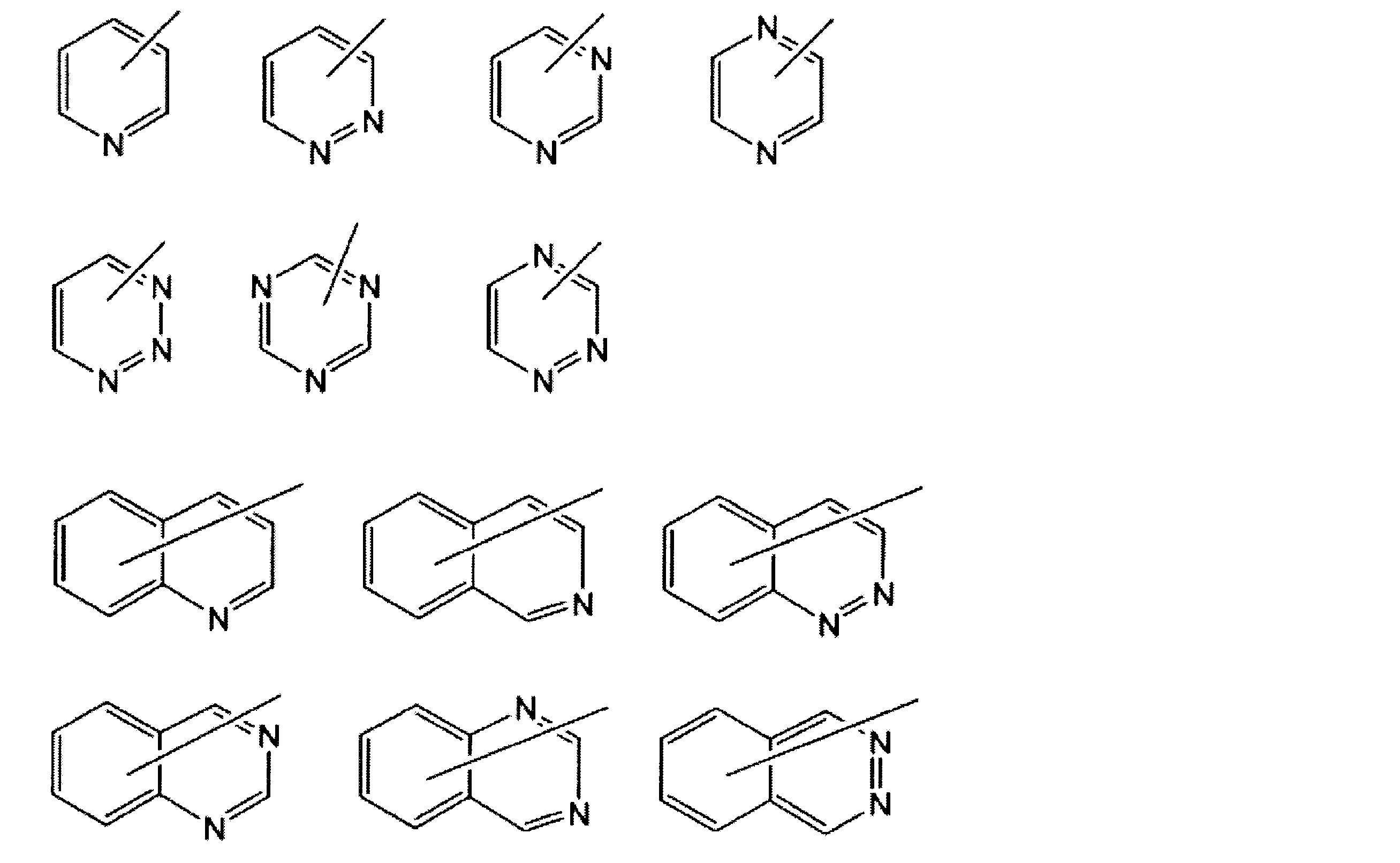


なお、Axの炭素数2~30の有機基の「炭素数」は、置換基の炭素原子を含まない有機基全体の総炭素数を意味する(後述するAyにて同じである。)。 Further, the ring of A x may have a plurality of the same or different substituents, and two adjacent substituents may be bonded together to form a ring. The ring formed may be monocyclic or condensed polycyclic.
The “carbon number” of the organic group having 2 to 30 carbon atoms in A x means the total number of carbon atoms in the whole organic group not including the carbon atom of the substituent (the same applies to A y described later). .
置換基を有していてもよい炭素数2~20のアルケニル基の炭素数は、2~12であることが好ましい。 Examples of the alkenyl group having 2 to 20 carbon atoms which may have a substituent of A y include a vinyl group, a propenyl group, an isopropenyl group, a butenyl group, an isobutenyl group, and a pentenyl group. Group, hexenyl group, heptenyl group, octenyl group, decenyl group, undecenyl group, dodecenyl group, tridecenyl group, tetradecenyl group, pentadecenyl group, hexadecenyl group, heptadecenyl group, octadecenyl group, nonadecenyl group, icosenyl group and the like.
The carbon number of the alkenyl group having 2 to 20 carbon atoms which may have a substituent is preferably 2 to 12.
R4の、炭素数1~20のアルキル基、及び炭素数2~20のアルケニル基の具体例は、前記Ayの、炭素数1~20のアルキル基、炭素数2~20のアルケニル基の例として列記したものと同様のものが挙げられる。 Of A y, in the group represented by -SO 2 -R 4, R 4 is an alkyl group having 1 to 20 carbon atoms, an alkenyl group having 2 to 20 carbon atoms, a phenyl group, or a 4-methylphenyl group To express.
Specific examples of the alkyl group having 1 to 20 carbon atoms and the alkenyl group having 2 to 20 carbon atoms in R 4 include the alkyl group having 1 to 20 carbon atoms and the alkenyl group having 2 to 20 carbon atoms in the above Ay . Examples are the same as those listed.
Ayの、置換基を有していてもよい炭素数3~12のシクロアルキル基、置換基を有してもよい炭素数6~12の芳香族炭化水素基、置換基を有していてもよい炭素数3~9の芳香族複素環基の置換基としては、フッ素原子、炭素数1~6のアルキル基、炭素数1~6のアルコキシ基、シアノ基が好ましい。 Ay , an alkyl group having 1 to 20 carbon atoms which may have a substituent, an alkenyl group having 2 to 20 carbon atoms which may have a substituent, and an optionally substituted carbon Examples of the substituent of the alkynyl group having 2 to 20 carbon atoms include a halogen atom, a cyano group, an alkoxy group having 1 to 20 carbon atoms, an alkoxy group having 1 to 12 carbon atoms substituted with an alkoxy group having 1 to 12 carbon atoms, phenyl Group, cyclohexyl group, C2-C12 cyclic ether group, C6-C14 aryloxy group, hydroxyl group, benzodioxanyl group, phenylsulfonyl group, 4-methylphenylsulfonyl group, benzoyl group, -SR 10 Is preferred. Here, R 10 represents the same meaning as described above.
A y having an optionally substituted cycloalkyl group having 3 to 12 carbon atoms, an optionally substituted aromatic hydrocarbon group having 6 to 12 carbon atoms, and a substituent. As the substituent of the aromatic heterocyclic group having 3 to 9 carbon atoms, a fluorine atom, an alkyl group having 1 to 6 carbon atoms, an alkoxy group having 1 to 6 carbon atoms, and a cyano group are preferable.


また、これらの環は置換基を有していてもよい。かかる置換基としては、Axが有する芳香環の置換基として例示したのと同様のものが挙げられる。 (In the formula, X, Y and Z have the same meaning as described above.)
Moreover, these rings may have a substituent. Such substituent groups include the same ones as exemplified as the substituents of the aromatic ring within A x.
(α)Axが炭素数4~30の、芳香族炭化水素基又は芳香族複素環基であり、Ayが水素原子、炭素数3~8のシクロアルキル基、(ハロゲン原子、シアノ基、炭素数1~6のアルキル基、炭素数1~6のアルコキシ基、若しくは炭素数3~8のシクロアルキル基)を置換基として有していてもよい炭素数6~12の芳香族炭化水素基、(ハロゲン原子、炭素数1~6のアルキル基、炭素数1~6のアルコキシ基、シアノ基)を置換基として有していてもよい炭素数3~9の芳香族複素環基、置換基を有していてもよい炭素数1~20のアルキル基、置換基を有していてもよい炭素数1~20のアルケニル基、置換基を有していてもよい炭素数2~20のアルキニル基であり、当該置換基が、ハロゲン原子、シアノ基、炭素数1~20のアルコキシ基、炭素数1~12のアルコキシ基で置換された炭素数1~12のアルコキシ基、フェニル基、シクロヘキシル基、炭素数2~12の環状エーテル基、炭素数6~14のアリールオキシ基、水酸基、ベンゾジオキサニル基、ベンゼンスルホニル基、ベンゾイル基、-SR10のいずれかである組み合わせ、及び、
(β)AxとAyが一緒になって不飽和複素環又は不飽和炭素環を形成しているもの、
が挙げられる。ここで、R10は前記と同じ意味を表す。 As a preferable combination of A x and A y ,
(Α) A x is an aromatic hydrocarbon group or aromatic heterocyclic group having 4 to 30 carbon atoms, A y is a hydrogen atom, a cycloalkyl group having 3 to 8 carbon atoms, (halogen atom, cyano group, An aromatic hydrocarbon group having 6 to 12 carbon atoms which may have a substituent of an alkyl group having 1 to 6 carbon atoms, an alkoxy group having 1 to 6 carbon atoms, or a cycloalkyl group having 3 to 8 carbon atoms) , (Halogen atom, alkyl group having 1 to 6 carbon atoms, alkoxy group having 1 to 6 carbon atoms, cyano group) which may have as a substituent a C 3-9 aromatic heterocyclic group or substituent An optionally substituted alkyl group having 1 to 20 carbon atoms, an optionally substituted alkenyl group having 1 to 20 carbon atoms, and an optionally substituted alkynyl group having 2 to 20 carbon atoms. And the substituent is a halogen atom, a cyano group, or an aryl group having 1 to 20 carbon atoms. A ruxoxy group, an alkoxy group having 1 to 12 carbon atoms substituted with an alkoxy group having 1 to 12 carbon atoms, a phenyl group, a cyclohexyl group, a cyclic ether group having 2 to 12 carbon atoms, an aryloxy group having 6 to 14 carbon atoms, A combination of any one of a hydroxyl group, a benzodioxanyl group, a benzenesulfonyl group, a benzoyl group, and —SR 10 ; and
(Β) A x and A y taken together to form an unsaturated heterocyclic ring or unsaturated carbocyclic ring,
Is mentioned. Here, R 10 represents the same meaning as described above.
(γ)Axが下記構造を有する基のいずれかであり、Ayが水素原子、炭素数3~8のシクロアルキル基、(ハロゲン原子、シアノ基、炭素数1~6のアルキル基、炭素数1~6のアルコキシ基、若しくは炭素数3~8のシクロアルキル基)を置換基として有していてもよい炭素数6~12の芳香族炭化水素基、(ハロゲン原子、炭素数1~6のアルキル基、炭素数1~6のアルコキシ基、シアノ基)を置換基として有していてもよい炭素数3~9の芳香族複素環基、置換基を有していてもよい炭素数1~20のアルキル基、置換基を有していてもよい炭素数1~20のアルケニル基、置換基を有していてもよい炭素数2~20のアルキニル基であり、当該置換基が、ハロゲン原子、シアノ基、炭素数1~20のアルコキシ基、炭素数1~12のアルコキシ基で置換された炭素数1~12のアルコキシ基、フェニル基、シクロヘキシル基、炭素数2~12の環状エーテル基、炭素数6~14のアリールオキシ基、水酸基、ベンゾジオキサニル基、ベンゼンスルホニル基、ベンゾイル基、-SR10のいずれかである組み合わせである。ここで、R10は前記と同じ意味を表す。 As a more preferable combination of Ax and Ay ,
(Γ) A x is any of the groups having the following structure, and A y is a hydrogen atom, a cycloalkyl group having 3 to 8 carbon atoms, (a halogen atom, a cyano group, an alkyl group having 1 to 6 carbon atoms, carbon An aromatic hydrocarbon group having 6 to 12 carbon atoms which may have an alkoxy group having 1 to 6 carbon atoms or a cycloalkyl group having 3 to 8 carbon atoms as a substituent, (halogen atom, 1 to 6 carbon atoms) An alkyl group having 1 to 6 carbon atoms, an alkoxy group having 1 to 6 carbon atoms, or a cyano group) as an optionally substituted aromatic heterocyclic group having 3 to 9 carbon atoms or an optionally substituted carbon atom having 1 carbon atom. An alkyl group having 1 to 20 carbon atoms, an alkenyl group having 1 to 20 carbon atoms which may have a substituent, and an alkynyl group having 2 to 20 carbon atoms which may have a substituent. Atoms, cyano groups, alkoxy groups having 1 to 20 carbon atoms, 1 to 1 carbon atoms An alkoxy group having 1 to 12 carbon atoms, a phenyl group, a cyclohexyl group, a cyclic ether group having 2 to 12 carbon atoms, an aryloxy group having 6 to 14 carbon atoms, a hydroxyl group, and a benzodioxanyl group. , benzenesulfonyl group, a benzoyl group, a combination is either -SR 10. Here, R 10 represents the same meaning as described above.


AxとAyの特に好ましい組み合わせとしては、
(δ)Axが下記構造を有する基のいずれかであり、Ayが水素原子、炭素数3~8のシクロアルキル基、(ハロゲン原子、シアノ基、炭素数1~6のアルキル基、炭素数1~6のアルコキシ基、若しくは炭素数3~8のシクロアルキル基)を置換基として有していてもよい炭素数6~12の芳香族炭化水素基、(ハロゲン原子、炭素数1~6のアルキル基、炭素数1~6のアルコキシ基、シアノ基)を置換基として有していてもよい炭素数3~9の芳香族複素環基、置換基を有していてもよい炭素数1~20のアルキル基、置換基を有していてもよい炭素数1~20のアルケニル基、置換基を有していてもよい炭素数2~20のアルキニル基であり、当該置換基が、ハロゲン原子、シアノ基、炭素数1~20のアルコキシ基、炭素数1~12のアルコキシ基で置換された炭素数1~12のアルコキシ基、フェニル基、シクロヘキシル基、炭素数2~12の環状エーテル基、炭素数6~14のアリールオキシ基、水酸基、ベンゾジオキサニル基、ベンゼンスルホニル基、ベンゾイル基、-SR10のいずれかである組合せである。下記式中、Xは前記と同じ意味を表す。ここで、R10は前記と同じ意味を表す。 (In the formula, X and Y have the same meaning as described above.)
As a particularly preferred combination of A x and A y ,
(Δ) A x is any of the groups having the following structure, and A y is a hydrogen atom, a cycloalkyl group having 3 to 8 carbon atoms, a (halogen atom, a cyano group, an alkyl group having 1 to 6 carbon atoms, carbon An aromatic hydrocarbon group having 6 to 12 carbon atoms which may have an alkoxy group having 1 to 6 carbon atoms or a cycloalkyl group having 3 to 8 carbon atoms as a substituent, (halogen atom, 1 to 6 carbon atoms) An alkyl group having 1 to 6 carbon atoms, an alkoxy group having 1 to 6 carbon atoms, or a cyano group) as an optionally substituted aromatic heterocyclic group having 3 to 9 carbon atoms or an optionally substituted carbon atom having 1 carbon atom. An alkyl group having 1 to 20 carbon atoms, an alkenyl group having 1 to 20 carbon atoms which may have a substituent, and an alkynyl group having 2 to 20 carbon atoms which may have a substituent. Atoms, cyano groups, alkoxy groups having 1 to 20 carbon atoms, 1 to 1 carbon atoms An alkoxy group having 1 to 12 carbon atoms, a phenyl group, a cyclohexyl group, a cyclic ether group having 2 to 12 carbon atoms, an aryloxy group having 6 to 14 carbon atoms, a hydroxyl group, and a benzodioxanyl group. , benzenesulfonyl group, a benzoyl group, a combination is either -SR 10. In the following formula, X represents the same meaning as described above. Here, R 10 represents the same meaning as described above.

なお、下記式においては、結合状態をより明確にすべく、置換基Y1、Y2を便宜上記載している(Y1、Y2は、前記と同じ意味を表す。以下にて同じ。)。 A 1 represents a trivalent aromatic group which may have a substituent. The trivalent aromatic group may be a trivalent carbocyclic aromatic group or a trivalent heterocyclic aromatic group. From the viewpoint of better expressing the desired effect of the present invention, a trivalent carbocyclic aromatic group is preferable, a trivalent benzene ring group or a trivalent naphthalene ring group is more preferable, and a trivalent represented by the following formula: The benzene ring group or trivalent naphthalene ring group is more preferable.
In the following formula, the substituents Y 1 and Y 2 are described for convenience in order to clarify the bonding state (Y 1 and Y 2 represent the same meaning as described above, and the same applies hereinafter). .


炭素数3~30の二価の脂環式炭化水素基としては、炭素数3~30のシクロアルカンジイル基、炭素数10~30の二価の脂環式縮合環基等が挙げられる。 A 2 and A 3 each independently represents a C 3-30 divalent alicyclic hydrocarbon group which may have a substituent.
Examples of the divalent alicyclic hydrocarbon group having 3 to 30 carbon atoms include a cycloalkanediyl group having 3 to 30 carbon atoms and a divalent alicyclic condensed ring group having 10 to 30 carbon atoms.

前記炭素数3~30の二価の脂環式炭化水素基は、Y1、Y3(又はY2、Y4)と結合する炭素原子の立体配置の相違に基づく、シス型、トランス型の立体異性体が存在し得る。例えば、シクロヘキサン-1,4-ジイル基の場合には、下記に示すように、シス型の異性体(A32a)とトランス型の異性体(A32b)が存在し得る。 Is more preferable, and the group represented by the formula (A32) is particularly preferable.
The divalent alicyclic hydrocarbon group having 3 to 30 carbon atoms is a cis type or a trans type based on a difference in configuration of carbon atoms bonded to Y 1 , Y 3 (or Y 2 , Y 4 ). Stereoisomers can exist. For example, in the case of a cyclohexane-1,4-diyl group, as shown below, a cis-type isomer (A32a) and a trans-type isomer (A32b) may exist.

A4、A5の芳香族基は単環のものであっても、多環のものであってもよい。
A4、A5の好ましい具体例としては、下記のものが挙げられる。 A 4 and A 5 each independently represents a divalent aromatic group having 6 to 30 carbon atoms which may have a substituent.
The aromatic groups of A 4 and A 5 may be monocyclic or polycyclic.
Preferable specific examples of A 4 and A 5 include the following.


置換基を有していてもよい炭素数1~6のアルキル基としては、前記AXで例示したのと同様のものが挙げられる。
これらの中でも、Q1は、水素原子又は炭素数1~6のアルキル基が好ましく、水素原子及びメチル基がより好ましい。 Q 1 represents a hydrogen atom or an alkyl group having 1 to 6 carbon atoms which may have a substituent.
The alkyl group which has 1 carbon atoms which may be ~ 6 have a substituent, the same ones as exemplified in the A X and the like.
Among these, Q 1 is preferably a hydrogen atom or an alkyl group having 1 to 6 carbon atoms, more preferably a hydrogen atom or a methyl group.
組成物(A)は、任意の成分として、重合性モノマーを含有しうる。本願において、「重合性モノマー」とは、重合能を有しモノマーとして働きうる化合物のうち、特に、逆波長分散重合性液晶化合物以外の化合物をいう。
重合性モノマーとしては、例えば、1分子当たり1以上の重合性基を有するものを用いうる。そのような重合性基を有することにより、光学異方性層の形成に際し重合を達成することができる。重合性モノマーが1分子当たり2以上の重合性基を有する架橋性モノマーである場合、架橋的な重合を達成することができる。かかる重合性基の例としては、化合物(I)中の基Z1-Y7-及びZ2-Y8-と同様の基を挙げることができ、より具体的には例えば、アクリロイル基、メタクリロイル基、及びエポキシ基を挙げることができる。 [1.4.3. Polymerizable monomer)
The composition (A) can contain a polymerizable monomer as an optional component. In the present application, the “polymerizable monomer” refers to a compound other than the reverse wavelength dispersion polymerizable liquid crystal compound, among compounds having a polymerization ability and capable of functioning as a monomer.
As the polymerizable monomer, for example, one having one or more polymerizable groups per molecule can be used. By having such a polymerizable group, polymerization can be achieved in forming the optically anisotropic layer. When the polymerizable monomer is a crosslinkable monomer having two or more polymerizable groups per molecule, crosslinkable polymerization can be achieved. Examples of the polymerizable group include the same groups as the groups Z 1 -Y 7 -and Z 2 -Y 8- in the compound (I), and more specifically, for example, acryloyl group, methacryloyl Groups and epoxy groups.
重合性モノマーは、既知の製造方法により製造することができる。または、化合物(I)と類似の構造を持つものについては、化合物(I)の製造方法に準じて製造することができる。 In the composition (A), the blending ratio of the polymerizable monomer is usually 1 to 100 parts by weight, preferably 5 to 50 parts by weight with respect to 100 parts by weight of the reverse wavelength dispersion polymerizable liquid crystal compound. Within the above range, precise control of the reverse wavelength dispersion characteristic is facilitated by appropriately adjusting the blending ratio of the polymerizable monomer so as to exhibit the desired reverse wavelength dispersion characteristic.
The polymerizable monomer can be produced by a known production method. Or what has a structure similar to compound (I) can be manufactured according to the manufacturing method of compound (I).
組成物(A)は、重合性液晶化合物及び重合性モノマーに加えて、必要に応じて、以下に例示するもの等の任意の成分を含みうる。 [1.4.4. Other components of composition (A)]
In addition to the polymerizable liquid crystal compound and the polymerizable monomer, the composition (A) may contain an optional component such as those exemplified below as necessary.
これらの重合開始剤は一種単独で、又は二種以上を組合わせて用いることができる。
組成物(A)において、重合開始剤の配合割合は、重合性化合物100重量部に対し、通常、0.1~30重量部、好ましくは0.5~10重量部である。 Examples of the cationic polymerization initiator include proton acids such as sulfuric acid, phosphoric acid, perchloric acid, and trifluoromethanesulfonic acid; Lewis acids such as boron trifluoride, aluminum chloride, titanium tetrachloride, and tin tetrachloride. An aromatic onium salt or a combination system of an aromatic onium salt and a reducing agent.
These polymerization initiators can be used alone or in combination of two or more.
In the composition (A), the blending ratio of the polymerization initiator is usually 0.1 to 30 parts by weight, preferably 0.5 to 10 parts by weight with respect to 100 parts by weight of the polymerizable compound.
本発明の光学異方性積層体は、前記本発明の複層フィルムから、光学異方性層を剥離し、これを長尺状の第二の基材に貼合してなる。 [2. Optically anisotropic laminate]
The optically anisotropic laminate of the present invention is obtained by peeling the optically anisotropic layer from the multilayer film of the present invention and bonding it to a long second substrate.
光学等方性の基材フィルムの材料の例としては、上に述べた第一の基材フィルムと同様のものの他にセルロースエステル等が挙げられる。そのような材料の長尺状フィルムを形成し、これを延伸せず、そのまま第二の基材として用いうる。第二の基材として、光学等方性の基材フィルムを備える光学異方性積層体は、そのまま、表示装置等の光学装置に組み込み、光学部材として用いうる。 Another example of the second substrate is an optically isotropic substrate film. Specifically, the optical isotropy is that the in-plane retardation Re is preferably less than 10 nm, and more preferably less than 5 nm. Moreover, in the optically isotropic base material, the retardation Rth in the thickness direction is also preferably less than 10 nm, and more preferably less than 5 nm. The lower limit of the in-plane retardation Re can be 0 nm. The lower limit of the retardation Rth in the thickness direction is preferably more than −10 nm, and more preferably more than −5 nm.
Examples of the material of the optically isotropic substrate film include cellulose esters and the like in addition to the same materials as the first substrate film described above. A long film of such a material is formed and can be used as it is as the second substrate without being stretched. An optically anisotropic laminate including an optically isotropic substrate film as a second substrate can be incorporated into an optical device such as a display device as it is and used as an optical member.
本発明の円偏光板は、1層以上の光学異方性層と、長尺状の直線偏光子とをロールツーロールで貼合してなる。 [3. (Circularly polarizing plate)
The circularly polarizing plate of the present invention is formed by laminating one or more optically anisotropic layers and a long linear polarizer by roll-to-roll.
円偏光板(i):光学異方性層と、長尺状の直線偏光子とをロールツーロールで貼合してなる円偏光板であって、光学異方性層が、前記本発明の複層フィルムから剥離してなる層である、円偏光板。
円偏光板(ii):長尺状のλ/4波長板と、長尺状のλ/2波長板と、長尺状の直線偏光子とを、ロールツーロールで貼合してなる円偏光板であって、長尺状のλ/4波長板、長尺状のλ/2波長板、またはこれらの両方が、前記本発明の複層フィルムから剥離した光学異方性層である、円偏光板。 Specific embodiments of the circularly polarizing plate of the present invention include the following two embodiments.
Circularly polarizing plate (i): a circularly polarizing plate formed by laminating an optically anisotropic layer and a long linear polarizer by roll-to-roll, wherein the optically anisotropic layer is of the present invention. A circularly polarizing plate, which is a layer formed by peeling from a multilayer film.
Circularly polarizing plate (ii): Circularly polarized light obtained by laminating a long λ / 4 wavelength plate, a long λ / 2 wavelength plate, and a long linear polarizer by roll-to-roll. A circular λ / 4 wavelength plate, a long λ / 2 wavelength plate, or both of which are optically anisotropic layers peeled from the multilayer film of the present invention. Polarizer.
・当該円偏光板を、そのある一方の面から観察すると、λ/2波長板の遅相軸の方向が、直線偏光子の透過軸または吸収軸の方向から時計周りに15°シフトし、且つλ/4波長板の遅相軸の方向が、直線偏光子の透過軸または吸収軸の方向から時計周りに75°シフトしている。
・当該円偏光板を、そのある一方の面から観察すると、λ/2波長板の遅相軸の方向が、直線偏光子の透過軸または吸収軸の方向から反時計周りに15°シフトし、且つλ/4波長板の遅相軸の方向が、直線偏光子の透過軸または吸収軸の方向から反時計周りに75°シフトしている。 In a certain product (multilayer film, circularly polarizing plate, display device, etc.) according to the present invention, the direction of the in-plane optical axis (slow axis, transmission axis, absorption axis, etc.) and geometric direction (longitudinal direction of the film And the width direction, etc.) are defined such that a shift in one direction is positive and a shift in another direction is negative, and the positive and negative directions are commonly defined in the components in the product. For example, in a certain circularly polarizing plate, “the direction of the slow axis of the λ / 2 wavelength plate relative to the direction of the transmission axis or absorption axis of the linear polarizer is 15 °, and the direction of the transmission axis or absorption axis of the linear polarizer is λ “The direction of the slow axis of the quarter-wave plate is 75 °” represents the following two cases:
When the circularly polarizing plate is observed from one surface thereof, the direction of the slow axis of the λ / 2 wave plate is shifted 15 ° clockwise from the direction of the transmission axis or absorption axis of the linear polarizer, and The direction of the slow axis of the λ / 4 wave plate is shifted by 75 ° clockwise from the direction of the transmission axis or absorption axis of the linear polarizer.
-When the circularly polarizing plate is observed from one side thereof, the direction of the slow axis of the λ / 2 wavelength plate is shifted 15 ° counterclockwise from the direction of the transmission axis or absorption axis of the linear polarizer, In addition, the direction of the slow axis of the λ / 4 wavelength plate is shifted by 75 ° counterclockwise from the direction of the transmission axis or absorption axis of the linear polarizer.
本発明の円偏光板は、液晶表示装置、有機EL表示装置等の表示装置の構成要素として用いうる。特に、好ましい態様として、本発明の有機EL表示装置は、前記本発明の円偏光板を備える。具体的には、本発明の有機EL表示装置は、表示素子の有機EL素子を有する表示装置において、上で説明した通り、反射防止フィルムとして本発明の円偏光板を備えうる。 [4. Display device)
The circularly polarizing plate of the present invention can be used as a component of a display device such as a liquid crystal display device or an organic EL display device. In particular, as a preferred embodiment, the organic EL display device of the present invention includes the circularly polarizing plate of the present invention. Specifically, the organic EL display device of the present invention can include the circularly polarizing plate of the present invention as an antireflection film as described above in a display device having an organic EL element as a display element.
以下の説明において、量を表す「%」及び「部」は、別に断らない限り重量基準である。また、以下に説明する操作は、別に断らない限り、常温及び常圧の条件において行った。 EXAMPLES Hereinafter, the present invention will be specifically described with reference to examples. However, the present invention is not limited to the examples described below, and is within the scope of the claims of the present invention and the equivalents thereof. You may carry out by changing arbitrarily.
In the following description, “%” and “part” representing amounts are based on weight unless otherwise specified. In addition, the operations described below were performed under normal temperature and normal pressure conditions unless otherwise specified.
〔第一の基材及び中間フィルムの遅相軸方向及び配向角バラツキの測定〕
偏光顕微鏡(オリンパス社製、偏光顕微鏡BX51)を用いてフィルムの幅方向に対し50mmの間隔で配向角の測定を行いその平均値を平均配向角(即ち幅方向に対する遅相軸方向)とし、配向角の最大値と配向角の最小値の差を配向角バラツキとした。 〔Evaluation methods〕
[Measurement of slow axis direction and orientation angle variation of first substrate and intermediate film]
Using a polarizing microscope (Olympus, polarizing microscope BX51), the orientation angle is measured at an interval of 50 mm with respect to the width direction of the film, and the average value is taken as the average orientation angle (that is, the slow axis direction with respect to the width direction). The difference between the maximum value of the angle and the minimum value of the orientation angle was defined as the orientation angle variation.
位相差計(AxoScan:Axometrics社製)を用いて、フィルムの幅方向に50mm間隔で590nmにおけるReおよびNz係数を測定し、それらの平均値をそれぞれReおよびNz係数とした。 [Measurement of Re of first substrate and intermediate film and Nz coefficient of first substrate]
Using a phase difference meter (AxoScan: manufactured by Axometrics), Re and Nz coefficients at 590 nm were measured at 50 mm intervals in the width direction of the film, and the average values thereof were taken as Re and Nz coefficients, respectively.
光学異方性層をガラス板に転写したサンプルにおいて、AxoScan(Axometrics社製)を用いて、測定波長590nmで測定した。 [Measurement of Re and slow axis direction of optically anisotropic layer]
In the sample in which the optically anisotropic layer was transferred to the glass plate, measurement was performed at a measurement wavelength of 590 nm using AxoScan (manufactured by Axometrics).
光学異方性層をガラス板に転写したサンプルを作製し、2枚の直線偏光子(偏光子及び検光子)の間に置いた。この際、前記の直線偏光子は、厚み方向から見て、互いの偏光透過軸が垂直になるように、向きを設定した。また、光学異方性層の遅相軸方向は、厚み方向から見て、直線偏光子の偏光透過軸と平行又は垂直になるように設定し、このサンプルを透過する光の透過率(クロスニコル透過率)を、日本分光社製の分光光度計「V7200」及び自動偏光フィルム測定装置「VAP-7070S」を用いて測定し、下記の基準で評価した。
優:ボトムとなる波長におけるクロスニコル透過率が0.010%以下。
良:ボトムとなる波長におけるクロスニコル透過率が0.010%超0.020%以下。
可:ボトムとなる波長におけるクロスニコル透過率が0.020%超0.030%以下。
不可:ボトムとなる波長におけるクロスニコル透過率が0.030%超。 (Evaluation of orientation state)
A sample in which the optically anisotropic layer was transferred to a glass plate was prepared, and placed between two linear polarizers (a polarizer and an analyzer). At this time, the direction of the linear polarizer was set so that the polarization transmission axes of the linear polarizers were perpendicular to each other when viewed from the thickness direction. The slow axis direction of the optically anisotropic layer is set to be parallel or perpendicular to the polarization transmission axis of the linear polarizer as viewed from the thickness direction, and the transmittance of light transmitted through this sample (crossed Nicols). The transmittance was measured using a spectrophotometer “V7200” manufactured by JASCO Corporation and an automatic polarizing film measuring device “VAP-7070S”, and evaluated according to the following criteria.
Excellent: Cross Nicol transmittance at the bottom wavelength is 0.010% or less.
Good: Cross Nicol transmittance at the bottom wavelength is more than 0.010% and 0.020% or less.
Good: Cross Nicol transmittance at the bottom wavelength is more than 0.020% and 0.030% or less.
Impossible: Cross Nicol transmittance at the bottom wavelength exceeds 0.030%.
配向状態の評価に用いたものと同様のサンプルを10cm角のサイズにカットし、偏光顕微鏡を用いてシュリーレン欠陥の個数を計数した。サンプルの1cm角内におけるシュリーレン欠陥の数により、配向欠陥を、以下の3段階で評価した。
A:1cm角内におけるシュリーレン欠陥の数が10個以下
B:1cm角内におけるシュリーレン欠陥の数が11個以上20個以下
C:1cm角内におけるシュリーレン欠陥の数が21個以上 (Evaluation of orientation defects)
Samples similar to those used for evaluation of the orientation state were cut into a 10 cm square size, and the number of schlieren defects was counted using a polarizing microscope. Orientation defects were evaluated in the following three stages according to the number of schlieren defects within a 1 cm square of the sample.
A: The number of schlieren defects in a 1 cm square is 10 or less. B: The number of schlieren defects in a 1 cm square is 11 or more and 20 or less. C: The number of schlieren defects in a 1 cm square is 21 or more.
光学異方性層を、偏光顕微鏡を用いて観察し、光学異方性層における輝点及び異物を計数し、サンプルの1cm角内における輝点・異物の数により、以下の4段階で評価した。
SA:1cm角内における輝点の数が0個
A:1cm角内における輝点の数が1個以上5個以下
B:1cm角内における輝点の数が6個以上15個以下
C:1cm角内における輝点の数が16個以上 [Evaluation of bright spots and foreign substances]
The optically anisotropic layer was observed using a polarizing microscope, the bright spots and foreign matters in the optical anisotropic layer were counted, and evaluated according to the following four stages according to the number of bright spots and foreign matters within 1 cm square of the sample. .
SA: The number of bright spots in a 1 cm square is 0 A: The number of bright spots in a 1 cm square is 1 or more and 5 or less B: The number of bright spots in a 1 cm square is 6 or more and 15 or less C: 1
円偏光板を拡散反射板(商品名「メタルミーTS50」、東レ社製、アルミ蒸着PET(ポリエチレンテレフタレート)フィルム)の上に置き、正面コントラストおよび視野角特性を次の基準で評価した。
正面コントラストについては、正面から(即ち、円偏光板の面に垂直な方向から)目視観察して、観察された反射色に基づき評価した。反射色が特に黒い場合は「A」(最良)、黒い場合は「B」(良)、反射色が明るくて青くなる場合は「C」(不良)と評価した。
視野角特性については、正面から目視観察した場合と斜め45°から目視観察した場合の、反射色、明るさおよび色むらに基づき評価した。
正面から観察した場合と斜め45°から観察した場合とで反射色と明るさに変化がなく、且つ斜め45°から観察した場合に色むらが見えない場合は「A」(最良)と評価した。
正面から観察した場合と斜め45°から観察した場合とで反射色と明るさに変化がなく、且つ斜め45°から観察した場合に色むらがほとんど見えない場合は「B」(良好)と評価した。
正面から観察した場合と斜め45°から観察した場合とで反射色と明るさに変化があり、且つ斜め45°から観察した場合に色むらがかすかに見える場合は「C」(良好ではないが使用可)と評価した。
正面から観察した場合と斜め45°から観察した場合とで反射色と明るさに変化があり、且つ斜め45°から観察した場合に色むらがはっきり見える場合は「D」(不良)とした。 [Visual observation of circularly polarizing plate]
The circularly polarizing plate was placed on a diffuse reflector (trade name “Metal Me TS50”, manufactured by Toray Industries, Inc., aluminum vapor-deposited PET (polyethylene terephthalate) film), and the front contrast and viewing angle characteristics were evaluated according to the following criteria.
The front contrast was visually observed from the front (that is, from the direction perpendicular to the surface of the circularly polarizing plate) and evaluated based on the observed reflected color. When the reflected color was particularly black, it was evaluated as “A” (best), when it was black, “B” (good), and when the reflected color was bright and blue, “C” (bad).
The viewing angle characteristics were evaluated based on the reflected color, brightness, and color unevenness when visually observed from the front and when visually observed from an oblique 45 °.
When there was no change in reflected color and brightness when observed from the front and when observed from 45 ° obliquely, and when color unevenness was not seen when observed from 45 ° obliquely, it was evaluated as “A” (best). .
Evaluation is “B” (good) when there is no change in reflected color and brightness when observed from the front and when observed from 45 ° obliquely, and when color unevenness is hardly seen when observed from 45 ° obliquely. did.
If the reflected color and brightness change between when viewed from the front and when viewed from 45 ° obliquely, and when the color unevenness appears faint when observed from 45 ° obliquely, “C” (not good) Evaluation was possible.
When there was a change in the reflected color and brightness between when observed from the front and when observed from 45 ° obliquely, and when the color unevenness was clearly visible when observed from 45 ° obliquely, it was determined as “D” (defect).
熱可塑性ノルボルネン樹脂のペレット(日本ゼオン株式会社製、商品名「ZEONOR1420R」、Tg 137℃)を100℃で5時間乾燥させた。乾燥させたペレットを押し出し機に供給し、押し出し機内で溶融させ、ポリマーパイプおよびポリマーフィルターを通し、Tダイからキャスティングドラム上にシート状に押し出し、冷却し、マスキングフィルム(トレテガー社製、FF1025)で保護しながら巻取り、厚み100μm、幅1490mmの延伸前基材(A)のロールを得た。 [Production Example 1: Preparation of base material (A) before stretching]
A pellet of thermoplastic norbornene resin (manufactured by Zeon Corporation, trade name “ZEONOR1420R”, Tg 137 ° C.) was dried at 100 ° C. for 5 hours. The dried pellets are supplied to an extruder, melted in the extruder, passed through a polymer pipe and a polymer filter, extruded from a T-die onto a casting drum, cooled, and masked with a masking film (Treteger, FF1025). Winding while protecting, a roll of the base material (A) before stretching having a thickness of 100 μm and a width of 1490 mm was obtained.
熱可塑性ノルボルネン樹脂のペレットを、別のノルボルネン樹脂のペレット(日本ゼオン株式会社製、Tg 126℃)に変更した他は、製造例1と同様にして、厚み100μm、幅1490mmの延伸前基材(B)のロールを得た。 [Production Example 2: Preparation of base material (B) before stretching]
Except for changing the thermoplastic norbornene resin pellet to another norbornene resin pellet (manufactured by Nippon Zeon Co., Ltd., Tg 126 ° C.), in the same manner as in Production Example 1, the substrate before stretching (thickness: 100 μm, width: 1490 mm) A roll B) was obtained.
熱可塑性ノルボルネン樹脂のペレットを、別のノルボルネン樹脂のペレット(日本ゼオン株式会社製、Tg 126℃)に変更し、且つTダイを変更した他は、製造例1と同様にして、厚み60μm、幅1350mmの延伸前基材(C)のロールを得た。 [Production Example 3: Preparation of base material (C) before stretching]
The thickness of the thermoplastic norbornene resin pellets was changed to another norbornene resin pellets (manufactured by Nippon Zeon Co., Ltd., Tg 126 ° C.) and the T-die was changed in the same manner as in Production Example 1, with a thickness of 60 μm and a width. A roll of the base material (C) before stretching having a length of 1350 mm was obtained.
熱可塑性ノルボルネン樹脂のペレットを、別のノルボルネン樹脂のペレット(日本ゼオン株式会社製、Tg 126℃)に変更し、且つTダイを変更した他は、製造例1と同様にして、厚み90μm、幅1060mmの延伸前基材(D)のロールを得た。 [Production Example 4: Preparation of base material (D) before stretching]
The thickness of the thermoplastic norbornene resin pellet was changed to another norbornene resin pellet (manufactured by Nippon Zeon Co., Ltd., Tg 126 ° C.), and the T die was changed in the same manner as in Production Example 1, with a thickness of 90 μm and a width. A roll of base material (D) before stretching of 1060 mm was obtained.
重合性液晶化合物(商品名「LC242」BASF社製、式(A1)で示される化合物)24.15部、界面活性剤(商品名「フタージェントFTX-209F」、ネオス社製)0.12部、重合開始剤(商品名「IRGACURE379」、BASF社製)0.73重量部、及び溶媒(メチルエチルケトン)75.00部を混合し、液晶組成物を調製した。 [Production Example 5: Preparation of liquid crystal composition (A)]
24.15 parts of polymerizable liquid crystal compound (trade name “LC242” manufactured by BASF Corporation, compound represented by formula (A1)), 0.12 part of surfactant (trade name “Futgent FTX-209F”, manufactured by Neos) , 0.73 parts by weight of a polymerization initiator (trade name “IRGACURE 379”, manufactured by BASF) and 75.00 parts of a solvent (methyl ethyl ketone) were mixed to prepare a liquid crystal composition.

式(B1)で表される逆波長分散重合性液晶化合物21.25部、界面活性剤(商品名「サーフロンS420」、AGCセイミケミカル社製)0.11部、重合開始剤(商品名「IRGACURE379」、BASF社製)0.64部、及び溶媒(シクロペンタノン、日本ゼオン株式会社製)78.00部を混合し、液晶組成物を調製した。 [Production Example 6: Preparation of liquid crystal composition (B)]
21.25 parts of the reverse wavelength dispersion polymerizable liquid crystal compound represented by the formula (B1), 0.11 part of a surfactant (trade name “Surflon S420”, manufactured by AGC Seimi Chemical Co., Ltd.), a polymerization initiator (trade name “IRGACURE 379”) ”, 0.64 part of BASF) and 78.00 parts of a solvent (cyclopentanone, Nippon Zeon Co., Ltd.) were mixed to prepare a liquid crystal composition.

(1-1.第一の基材の調製)
製造例1で得た延伸前基材(A)のロールから、延伸前基材(A)を引き出し、連続的にマスキングフィルムを剥離してテンター延伸機に供給し、斜め延伸を行なった。これにより、中間フィルムを得た。斜め延伸における延伸倍率は1.9倍、延伸温度は132℃とし、得られた中間フィルムは、その平均配向角が幅方向に対して25°であり、Reが360nmであった。
得られた中間フィルムを、さらに自由縦一軸延伸にて延伸した。自由縦一軸延伸の延伸方向はフィルム搬送方向とし、延伸倍率は1.25倍、延伸温度は129℃とした。
延伸後、基材フィルム幅方向の両端をトリミングし、幅1350mmで長尺状の、第一の基材(A-1)を得た。得られた延伸基材の遅相軸は幅方向に対して45°、配向角のバラツキは0.5°、Nz係数は2.3、Reは141nm、膜厚は42μmであった。
得られた第一の基材(A-1)は、新たなマスキングフィルム(トレテガー社製、FF1025)で保護しながら巻取り、第一の基材(A-1)のロールを得た。 [Example 1]
(1-1. Preparation of first substrate)
The base material (A) before stretching was drawn from the roll of the base material (A) before stretching obtained in Production Example 1, and the masking film was continuously peeled off and supplied to a tenter stretching machine, and oblique stretching was performed. Thereby, an intermediate film was obtained. The stretching ratio in the oblique stretching was 1.9 times, the stretching temperature was 132 ° C., and the obtained intermediate film had an average orientation angle of 25 ° with respect to the width direction and Re of 360 nm.
The obtained intermediate film was further stretched by free longitudinal uniaxial stretching. The stretching direction of free longitudinal uniaxial stretching was the film transport direction, the stretching ratio was 1.25 times, and the stretching temperature was 129 ° C.
After stretching, both ends in the substrate film width direction were trimmed to obtain a first substrate (A-1) having a long width of 1350 mm. The obtained stretched substrate had a slow axis of 45 ° with respect to the width direction, an orientation angle variation of 0.5 °, an Nz coefficient of 2.3, Re of 141 nm, and a film thickness of 42 μm.
The obtained first base material (A-1) was rolled up while being protected with a new masking film (FF1025, manufactured by Treteger) to obtain a roll of the first base material (A-1).
(1-1)で得た第一の基材(A-1)のロールから、第一の基材(A-1)を繰り出し、マスキングフィルムを剥離して搬送した。室温25℃において、搬送される第一の基材(A-1)の一方の面(マスキングフィルムが貼合されていた側の面)に、製造例5で得た液晶組成物(A)を、ダイコーターを用いて直接塗布し、液晶組成物の層を形成した。
ダイコーターによる塗布は、固定されているダイコーターの吐出口を、搬送される第一の基材(A-1)の表面に近接させ、ダイコーターから液晶組成物(A)を吐出することにより行った。したがって、ダイコーターによる、搬送される第一の基材(A-1)の表面に対する相対的な塗布方向は、長手方向(即ち幅方向に対して90°)であった。 (1-2. Formation of Layer of Liquid Crystal Composition)
The first substrate (A-1) was fed out from the roll of the first substrate (A-1) obtained in (1-1), and the masking film was peeled off and conveyed. At room temperature of 25 ° C., the liquid crystal composition (A) obtained in Production Example 5 was applied to one surface (the surface on which the masking film was bonded) of the first substrate (A-1) to be conveyed. Then, it was directly applied using a die coater to form a liquid crystal composition layer.
The application by the die coater is performed by bringing the discharge port of the fixed die coater close to the surface of the first substrate (A-1) to be conveyed and discharging the liquid crystal composition (A) from the die coater. went. Therefore, the relative application direction with respect to the surface of the first substrate (A-1) to be conveyed by the die coater was the longitudinal direction (that is, 90 ° with respect to the width direction).
(1-2)で得た、第一の基材(A-1)上の液晶組成物の層を、110℃で2.5分間配向処理した。その後、窒素雰囲気下で、液晶組成物の層に、積算光量100mJ/cm2(照射強度10mW/cm2を照射時間10秒)以上の紫外線を照射して、液晶組成物中の重合性液晶化合物を重合させて、硬化液晶分子を形成した。これにより、乾燥膜厚1.1μmの、ホモジニアス配向した光学異方性層を得て、(第一の基材)/(光学異方性層)の層構成を有する複層フィルムを得た。 (1-3. Orientation treatment and polymerization)
The liquid crystal composition layer on the first substrate (A-1) obtained in (1-2) was subjected to an alignment treatment at 110 ° C. for 2.5 minutes. Thereafter, under a nitrogen atmosphere, the layer of the liquid crystal composition is irradiated with ultraviolet rays having an accumulated light amount of 100 mJ / cm 2 (irradiation intensity of 10 mW / cm 2 for an irradiation time of 10 seconds) or more, and the polymerizable liquid crystal compound in the liquid crystal composition Was polymerized to form cured liquid crystal molecules. Thus, a homogeneously oriented optically anisotropic layer having a dry film thickness of 1.1 μm was obtained, and a multilayer film having a layer configuration of (first substrate) / (optically anisotropic layer) was obtained.
得られた複層フィルムの光学異方性層について、面内レターデーションの測定、遅相軸と幅方向とがなす角度の測定、配向状態の評価、配向欠陥の評価、ならびに輝点及び異物の評価を行った。 (1-4. Evaluation)
For the optically anisotropic layer of the obtained multilayer film, measurement of in-plane retardation, measurement of angle between slow axis and width direction, evaluation of alignment state, evaluation of alignment defect, and bright spot and foreign matter Evaluation was performed.
以下の事項以外は実施例1と同様に操作し、第一の基材及び複層フィルムを得て評価した。
・(1-1)における延伸前基材(A)を斜め延伸して中間フィルムとする工程において、延伸温度を133℃とし、延伸の方向も変更した(延伸倍率は1.9倍で変更なし)。得られた中間フィルムは、その平均配向角が23°、Reが325nmであった(その後の自由縦一軸延伸の上限は変更なし)。
・(1-3)において、光学異方性層の乾燥膜厚を2.2μmに変更した。 [Example 2]
Except for the following items, the same operation as in Example 1 was performed to obtain and evaluate the first base material and the multilayer film.
In the process of obliquely stretching the base material (A) before stretching in (1-1) to form an intermediate film, the stretching temperature was 133 ° C., and the stretching direction was also changed (the stretching ratio was 1.9 times and no change) ). The obtained intermediate film had an average orientation angle of 23 ° and Re of 325 nm (the upper limit of free longitudinal uniaxial stretching thereafter was not changed).
In (1-3), the dry film thickness of the optically anisotropic layer was changed to 2.2 μm.
以下の事項以外は実施例1と同様に操作し、第一の基材及び複層フィルムを得て評価した。
・(1-1)における延伸前基材(A)を斜め延伸して中間フィルムとする工程において、延伸倍率を2.0倍、延伸温度を136℃とし、延伸の方向も変更した。得られた中間フィルムは、その平均配向角が幅方向に対して30°、Reが450nmであった。
・(1-1)における中間フィルムを自由縦一軸延伸にて延伸する工程において、延伸倍率を1.20倍、延伸温度を132℃に変更した。 Example 3
Except for the following items, the same operation as in Example 1 was performed to obtain and evaluate the first base material and the multilayer film.
In the process of obliquely stretching the base material (A) before stretching in (1-1) to form an intermediate film, the stretching ratio was 2.0 times, the stretching temperature was 136 ° C., and the stretching direction was also changed. The obtained intermediate film had an average orientation angle of 30 ° with respect to the width direction and Re of 450 nm.
In the step of stretching the intermediate film in (1-1) by free longitudinal uniaxial stretching, the stretching ratio was changed to 1.20 times and the stretching temperature was changed to 132 ° C.
以下の事項以外は実施例1と同様に操作し、第一の基材及び複層フィルムを得て評価した。
・(1-1)における延伸前基材(A)を斜め延伸して中間フィルムとする工程において、延伸倍率を3.0倍、延伸温度を131℃とし、延伸の方向も変更した。得られた中間フィルムは、その平均配向角が幅方向に対して15°、Reが300nmであった。
・(1-1)における中間フィルムを自由縦一軸延伸にて延伸する工程において、延伸倍率を1.40倍に変更した(延伸温度は129℃で変更なし)。 Example 4
Except for the following items, the same operation as in Example 1 was performed to obtain and evaluate the first base material and the multilayer film.
In the process of obliquely stretching the base material (A) before stretching in (1-1) to form an intermediate film, the stretching ratio was 3.0 times, the stretching temperature was 131 ° C., and the stretching direction was also changed. The obtained intermediate film had an average orientation angle of 15 ° with respect to the width direction and Re of 300 nm.
In the step of stretching the intermediate film in (1-1) by free longitudinal uniaxial stretching, the stretching ratio was changed to 1.40 times (the stretching temperature was 129 ° C. and not changed).
(5-1.第一の基材の調製)
製造例1で得た延伸前基材(A)のロールから、延伸前基材(A)を引き出し、連続的にマスキングフィルムを剥離して、自由縦一軸延伸し、中間フィルムを得た。自由縦一軸延伸の延伸方向はフィルム搬送方向とし、延伸倍率は1.2倍、延伸温度は140℃とした。得られた中間フィルムは、その平均配向角が幅方向に対して90°であり、Reが160nmであった。
得られた中間フィルムを、さらにテンター延伸機に供給し、斜め延伸を行なった。斜め延伸における延伸倍率は1.70倍、延伸温度は136℃とした。
延伸後、基材フィルム幅方向の両端をトリミングし、幅1350mmで長尺状の、第一の基材(A-1)を得た。得られた延伸基材の遅相軸は幅方向に対して45°、配向角のバラツキは0.3°、Nz係数は1.6、Reは140nm、膜厚は49μmであった。
得られた第一の基材(A-1)は、新たなマスキングフィルム(トレテガー社製、FF1025)で保護しながら巻取り、第一の基材(A-1)のロールを得た。 Example 5
(5-1. Preparation of first substrate)
From the roll of the base material (A) before stretching obtained in Production Example 1, the base material (A) before stretching was pulled out, the masking film was continuously peeled off, and free longitudinal uniaxial stretching was performed to obtain an intermediate film. The stretching direction of free longitudinal uniaxial stretching was the film conveying direction, the stretching ratio was 1.2 times, and the stretching temperature was 140 ° C. The obtained intermediate film had an average orientation angle of 90 ° with respect to the width direction and Re of 160 nm.
The obtained intermediate film was further supplied to a tenter stretching machine and subjected to oblique stretching. The stretching ratio in the oblique stretching was 1.70 times, and the stretching temperature was 136 ° C.
After stretching, both ends in the substrate film width direction were trimmed to obtain a first substrate (A-1) having a long width of 1350 mm. The stretched substrate thus obtained had a slow axis of 45 ° with respect to the width direction, an orientation angle variation of 0.3 °, an Nz coefficient of 1.6, an Re of 140 nm, and a film thickness of 49 μm.
The obtained first base material (A-1) was rolled up while being protected with a new masking film (FF1025, manufactured by Treteger) to obtain a roll of the first base material (A-1).
第一の基材(A-1)のロールとして、実施例1の(1-1)で得たものに代えて、(5-1)で得たものを用い、光学異方性層の乾燥膜厚を1.5μmに変更した他は、実施例1の(1-2)~(1-4)と同様にして、複層フィルムを製造し評価した。 (5-2. Production and evaluation of multilayer film)
As the roll of the first substrate (A-1), instead of the roll obtained in (1-1) of Example 1, the roll obtained in (5-1) was used, and the optically anisotropic layer was dried. A multilayer film was produced and evaluated in the same manner as in (1-2) to (1-4) of Example 1 except that the film thickness was changed to 1.5 μm.
以下の事項以外は実施例1と同様に操作し、第一の基材及び複層フィルムを得て評価した。
・(1-1)における延伸前基材(A)を斜め延伸して中間フィルムとする工程において、延伸倍率を1.25倍、延伸温度を135℃とし、延伸の方向も変更した。得られた中間フィルムは、その平均配向角が幅方向に対して15°、Reが140nmであった。
・(1-1)における中間フィルムを自由縦一軸延伸にて延伸する工程において、延伸倍率を1.60倍、延伸温度を138℃に変更した。
・(1-2)において、液晶組成物(A)に代えて、製造例6で得た液晶組成物(B)を用いた。
・(1-3)において、光学異方性層の乾燥膜厚を2.2μmに変更した。 Example 6
Except for the following items, the same operation as in Example 1 was performed to obtain and evaluate the first base material and the multilayer film.
In the process of obliquely stretching the substrate (A) before stretching in (1-1) to form an intermediate film, the stretching ratio was 1.25 times, the stretching temperature was 135 ° C., and the stretching direction was also changed. The obtained intermediate film had an average orientation angle of 15 ° with respect to the width direction and Re of 140 nm.
In the process of stretching the intermediate film in (1-1) by free longitudinal uniaxial stretching, the stretching ratio was changed to 1.60 times and the stretching temperature was changed to 138 ° C.
In (1-2), the liquid crystal composition (B) obtained in Production Example 6 was used in place of the liquid crystal composition (A).
In (1-3), the dry film thickness of the optically anisotropic layer was changed to 2.2 μm.
以下の事項以外は実施例1と同様に操作し、第一の基材及び複層フィルムを得て評価した。
・(1-1)において、延伸前基材(A)のロールに代えて、製造例2で得た延伸前基材(B)のロールを用いた。
・(1-1)における延伸前基材(A)を斜め延伸して中間フィルムとする工程において、延伸倍率を1.25倍、延伸温度を135℃とし、延伸の方向も変更した。得られた中間フィルムは、その平均配向角が幅方向に対して45°、Reが140nmであった。
・(1-1)における中間フィルムを自由縦一軸延伸にて延伸する工程において、延伸倍率を1.40倍、延伸温度を133℃に変更した。
・(1-3)において、光学異方性層の乾燥膜厚を1.2μmに変更した。 Example 7
Except for the following items, the same operation as in Example 1 was performed to obtain and evaluate the first base material and the multilayer film.
In (1-1), instead of the roll of the base material (A) before stretching, the roll of the base material (B) before stretching obtained in Production Example 2 was used.
In the process of obliquely stretching the substrate (A) before stretching in (1-1) to form an intermediate film, the stretching ratio was 1.25 times, the stretching temperature was 135 ° C., and the stretching direction was also changed. The obtained intermediate film had an average orientation angle of 45 ° with respect to the width direction and Re of 140 nm.
In the process of stretching the intermediate film in (1-1) by free longitudinal uniaxial stretching, the stretching ratio was changed to 1.40 times and the stretching temperature was changed to 133 ° C.
In (1-3), the dry film thickness of the optically anisotropic layer was changed to 1.2 μm.
(8-1.第一の基材の調製)
製造例3で得た延伸前基材(C)のロールから、延伸前基材(C)を引き出し、連続的にマスキングフィルムを剥離してテンター延伸機に供給し、斜め延伸を行なった。斜め延伸における延伸倍率は1.5倍、延伸温度は142℃とした。
延伸後、基材フィルム幅方向の両端をトリミングし、幅1350mmで長尺状の、第一の基材(A-1)を得た。得られた延伸基材の遅相軸は幅方向に対して15°、配向角のバラツキは0.7°、Nz係数は1.1、Reは141nm、膜厚は22μmであった。
得られた第一の基材(A-1)は、新たなマスキングフィルム(トレテガー社製、FF1025)で保護しながら巻取り、第一の基材(A-1)のロールを得た。 Example 8
(8-1. Preparation of first substrate)
The base material (C) before stretching was drawn from the roll of the base material (C) before stretching obtained in Production Example 3, and the masking film was continuously peeled off and supplied to a tenter stretching machine, and oblique stretching was performed. The stretching ratio in the oblique stretching was 1.5 times, and the stretching temperature was 142 ° C.
After stretching, both ends in the substrate film width direction were trimmed to obtain a first substrate (A-1) having a long width of 1350 mm. The obtained stretched substrate had a slow axis of 15 ° with respect to the width direction, an orientation angle variation of 0.7 °, an Nz coefficient of 1.1, an Re of 141 nm, and a film thickness of 22 μm.
The obtained first base material (A-1) was rolled up while being protected with a new masking film (FF1025, manufactured by Treteger) to obtain a roll of the first base material (A-1).
第一の基材(A-1)のロールとして、実施例1の(1-1)で得たものに代えて、(8-1)で得たものを用いた他は、実施例1の(1-2)~(1-4)と同様にして、複層フィルムを製造し評価した。 (8-2. Production and evaluation of multilayer film)
As the roll of the first base material (A-1), the roll obtained in (8-1) was used instead of the roll obtained in (1-1) of Example 1, and the roll of Example 1 was used. A multilayer film was produced and evaluated in the same manner as (1-2) to (1-4).
(9-1.第一の基材の調製)
製造例4で得た延伸前基材(D)のロールから、延伸前基材(D)を引き出し、連続的にマスキングフィルムを剥離してテンター延伸機に供給し、斜め延伸を行なった。斜め延伸における延伸倍率は1.96倍、延伸温度は142℃とした。
延伸後、基材フィルム幅方向の両端をトリミングし、幅1350mmで長尺状の、第一の基材(A-1)を得た。得られた延伸基材の遅相軸は幅方向に対して22.5°、配向角のバラツキは0.2°、Nz係数は1.35、Reは259nm、膜厚は43μmであった。
得られた第一の基材(A-1)は、新たなマスキングフィルム(トレテガー社製、FF1025)で保護しながら巻取り、第一の基材(A-1)のロールを得た。 Example 9
(9-1. Preparation of first substrate)
The base material (D) before stretching was drawn from the roll of the base material (D) before stretching obtained in Production Example 4, and the masking film was continuously peeled off and supplied to a tenter stretching machine, and oblique stretching was performed. The stretching ratio in the oblique stretching was 1.96 times, and the stretching temperature was 142 ° C.
After stretching, both ends in the substrate film width direction were trimmed to obtain a first substrate (A-1) having a long width of 1350 mm. The obtained stretched substrate had a slow axis of 22.5 ° in the width direction, an orientation angle variation of 0.2 °, an Nz coefficient of 1.35, an Re of 259 nm, and a film thickness of 43 μm.
The obtained first base material (A-1) was rolled up while being protected with a new masking film (FF1025, manufactured by Treteger) to obtain a roll of the first base material (A-1).
第一の基材(A-1)のロールとして、実施例1の(1-1)で得たものに代えて、(9-1)で得たものを用いた他は、実施例1の(1-2)~(1-4)と同様にして、複層フィルムを製造し評価した。 (9-2. Production and evaluation of multilayer film)
The roll of the first base material (A-1) is the same as that of Example 1 except that the roll obtained in (9-1) was used instead of the roll obtained in (1-1) of Example 1. A multilayer film was produced and evaluated in the same manner as (1-2) to (1-4).
以下の事項以外は実施例1と同様に操作し、第一の基材及び複層フィルムを得て評価した。
・(1-1)における延伸前基材(A)を斜め延伸して中間フィルムとする工程において、延伸倍率を3.0倍、延伸温度を131℃とし、延伸の方向も変更した。得られた中間フィルムは、その平均配向角が幅方向に対して15°、Reが300nmであった。
・(1-1)における中間フィルムを自由縦一軸延伸にて延伸する工程において、延伸倍率を1.80倍、延伸温度を128℃に変更した。 [Comparative Example 1]
Except for the following items, the same operation as in Example 1 was performed to obtain and evaluate the first base material and the multilayer film.
In the process of obliquely stretching the base material (A) before stretching in (1-1) to form an intermediate film, the stretching ratio was 3.0 times, the stretching temperature was 131 ° C., and the stretching direction was also changed. The obtained intermediate film had an average orientation angle of 15 ° with respect to the width direction and Re of 300 nm.
In the process of stretching the intermediate film in (1-1) by free longitudinal uniaxial stretching, the stretching ratio was changed to 1.80 times and the stretching temperature was changed to 128 ° C.
以下の事項以外は実施例1と同様に操作し、第一の基材及び複層フィルムを得て評価した。
・(1-1)における延伸前基材(A)を斜め延伸して中間フィルムとする工程において、延伸倍率を1.5倍、延伸温度を144℃とし、延伸の方向も変更した。得られた中間フィルムは、その平均配向角が幅方向に対して55°、Reが300nmであった。
・(1-1)における中間フィルムを自由縦一軸延伸にて延伸する工程において、延伸倍率を2.0倍、延伸温度を145℃に変更した。 [Comparative Example 2]
Except for the following items, the same operation as in Example 1 was performed to obtain and evaluate the first base material and the multilayer film.
In the process of obliquely stretching the base material (A) before stretching in (1-1) to form an intermediate film, the stretching ratio was 1.5 times, the stretching temperature was 144 ° C., and the stretching direction was also changed. The obtained intermediate film had an average orientation angle of 55 ° with respect to the width direction and Re of 300 nm.
In the step of stretching the intermediate film in (1-1) by free longitudinal uniaxial stretching, the stretching ratio was changed to 2.0 times and the stretching temperature was changed to 145 ° C.


(10-1.円偏光板の製造)
実施例1で得た複層フィルムの光学異方性層をλ/4波長板として用い、円偏光板を製造した。
まず、長尺状の直線偏光子として、偏光フィルム(サンリッツ社製、商品名「HLC2-5618S」、厚さ180μm、幅方向に対して0°の方向に透過軸を有する)を用意した。この一方の面と、実施例1で得た複層フィルムの光学異方性層(即ちλ/4波長板)側の面とを貼合した。貼合は粘着剤層(日東電工製、商品名「CS9621」)を介して行った。これにより、(偏光子)/(粘着剤層)/(λ/4波長板)/(第一の基材)の層構成を有する積層体(10-i)を得た。
次に、積層体(10-i)から、第一の基材を剥離し、(偏光子)/(粘着剤層)/(λ/4波長板)の層構成を有する円偏光板を得た。
これらの貼合及び剥離の操作は、いずれも、図1に例示する態様で、ロールツーロールにて連続的に行った。したがって、貼合の操作は、いずれも長尺状のフィルムの長手方向を揃えた状態で行った。
得られた円偏光板の構成要素の光学軸は、下記の角度関係を有していた。即ち、偏光子側の面から円偏光板を観察した場合において、λ/4波長板の遅相軸は、偏光板の透過軸の方向から時計周りに45°シフトしていた。 Example 10
(10-1. Manufacturing of circularly polarizing plate)
A circularly polarizing plate was produced using the optically anisotropic layer of the multilayer film obtained in Example 1 as a λ / 4 wavelength plate.
First, as a long linear polarizer, a polarizing film (manufactured by Sanlitz, trade name “HLC2-5618S”, thickness 180 μm, having a transmission axis in a direction of 0 ° with respect to the width direction) was prepared. This one surface was bonded to the surface of the multilayer film obtained in Example 1 on the side of the optically anisotropic layer (that is, the λ / 4 wavelength plate). Pasting was performed via an adhesive layer (manufactured by Nitto Denko, trade name “CS9621”). As a result, a laminate (10-i) having a layer configuration of (polarizer) / (adhesive layer) / (λ / 4 wavelength plate) / (first substrate) was obtained.
Next, the first substrate was peeled from the laminate (10-i) to obtain a circularly polarizing plate having a layer structure of (polarizer) / (adhesive layer) / (λ / 4 wavelength plate). .
Each of these bonding and peeling operations was continuously performed by roll-to-roll in the embodiment illustrated in FIG. Therefore, the operation of pasting was performed in a state where the longitudinal direction of the long film was aligned.
The optical axes of the components of the obtained circularly polarizing plate had the following angular relationship. That is, when the circularly polarizing plate was observed from the surface on the polarizer side, the slow axis of the λ / 4 wavelength plate was shifted 45 ° clockwise from the direction of the transmission axis of the polarizing plate.
(10-1)で得た長尺状の円偏光板を適当な大きさに裁断し、目視観察して評価した。 (10-2. Evaluation)
The long circular polarizing plate obtained in (10-1) was cut into an appropriate size and evaluated by visual observation.
複層フィルムとして、実施例1で得たものに代えて、実施例5で得たもの(実施例11)、又は実施例6で得たもの(実施例12)を用いた他は実施例10の(10-1)と同様に操作し、円偏光板を得た。
得られた円偏光板の構成要素の光学軸の角度関係は、実施例10で得た円偏光板と同様であった。
得られた長尺状の円偏光板を適当な大きさに裁断し、目視観察して評価した。 [Examples 11 to 12]
Example 10 except that the film obtained in Example 5 (Example 11) or the one obtained in Example 6 (Example 12) was used instead of the film obtained in Example 1 as the multilayer film. In the same manner as in (10-1), a circularly polarizing plate was obtained.
The angular relationship of the optical axes of the components of the obtained circularly polarizing plate was the same as that of the circularly polarizing plate obtained in Example 10.
The obtained long circularly polarizing plate was cut into an appropriate size and evaluated by visual observation.

実施例12で製造した円偏光板のλ/4波長板側の面と、反射板(商品名「メタルミーTS50」、東レ社製、アルミニウム蒸着PET(ポリエチレンテレフタレート)フィルム)の反射面とを貼合した。貼合は粘着剤層(日東電工製、商品名「CS9621」)を介して行った。これにより、(偏光子)/(粘着剤層)/(λ/4波長板)/(粘着剤層)/(反射板)の層構成を有する、評価用積層体(12-v)を得た。 Example 13
The surface on the λ / 4 wavelength plate side of the circularly polarizing plate manufactured in Example 12 and the reflective surface of a reflective plate (trade name “Metal Me TS50”, manufactured by Toray Industries, Inc., aluminum-deposited PET (polyethylene terephthalate) film) are bonded together. did. Pasting was performed via an adhesive layer (manufactured by Nitto Denko, trade name “CS9621”). Thus, an evaluation laminate (12-v) having a layer configuration of (polarizer) / (adhesive layer) / (λ / 4 wavelength plate) / (adhesive layer) / (reflector) was obtained. .
21 複層フィルム
30 直線偏光子
120 貼合装置
121 ニップロール
122 ニップロール
130 巻き軸 DESCRIPTION OF
Claims (15)
- 長尺状の第一の基材と、
前記第一の基材上に直接形成された、硬化液晶分子を含む光学異方性層とを備える複層フィルムであって、
前記第一の基材は、そのNz係数が1.1~3.0、配向角のバラツキが1.0°以下であって、延伸により生じた配向規制力を有し、
前記第一の基材の遅相軸と、前記第一の基材の幅方向とがなす角度が0°以上90°未満である、複層フィルム。 A long first base material;
A multilayer film comprising an optically anisotropic layer comprising cured liquid crystal molecules formed directly on the first substrate,
The first base material has an Nz coefficient of 1.1 to 3.0, an orientation angle variation of 1.0 ° or less, and an orientation regulating force generated by stretching,
The multilayer film whose angle which the slow axis of said 1st base material and the width direction of said 1st base material make is 0 degree or more and less than 90 degrees. - 前記第一の基材の遅相軸と前記第一の基材の幅方向とがなす角度が40°~80°である、請求項1に記載の複層フィルム。 2. The multilayer film according to claim 1, wherein an angle formed by the slow axis of the first substrate and the width direction of the first substrate is 40 ° to 80 °.
- 前記第一の基材の遅相軸と前記第一の基材の幅方向とがなす角度が55°~80°である、請求項2に記載の複層フィルム。 The multilayer film according to claim 2, wherein an angle formed by the slow axis of the first substrate and the width direction of the first substrate is 55 ° to 80 °.
- 前記第一の基材が正の固有複屈折性を有する樹脂のフィルムである、請求項1~3のいずれか1項に記載の複層フィルム。 The multilayer film according to any one of claims 1 to 3, wherein the first base material is a resin film having positive intrinsic birefringence.
- 前記第一の基材が脂環式構造含有重合体を含む樹脂のフィルムである、請求項1~4のいずれか1項に記載の複層フィルム。 The multilayer film according to any one of claims 1 to 4, wherein the first base material is a resin film containing an alicyclic structure-containing polymer.
- 前記第一の基材が、1回以上の斜め延伸を含む延伸工程により延伸された延伸フィルムである、請求項1~5のいずれか1項に記載の複層フィルム。 The multilayer film according to any one of claims 1 to 5, wherein the first base material is a stretched film stretched by a stretching process including one or more oblique stretching.
- 前記光学異方性層が逆波長分散性を有する、請求項1~6のいずれか1項に記載の複層フィルム。 The multilayer film according to any one of claims 1 to 6, wherein the optically anisotropic layer has reverse wavelength dispersion.
- 前記光学異方性層がλ/4波長板である、請求項1~7のいずれか1項に記載の複層フィルム。 The multilayer film according to any one of claims 1 to 7, wherein the optically anisotropic layer is a λ / 4 wavelength plate.
- 前記光学異方性層がλ/2波長板である、請求項1~7のいずれか1項に記載の複層フィルム。 The multilayer film according to any one of claims 1 to 7, wherein the optically anisotropic layer is a λ / 2 wavelength plate.
- 前記光学異方性層の厚みが5μm以下である、請求項1~9のいずれか1項に記載の複層フィルム。 The multilayer film according to any one of claims 1 to 9, wherein the thickness of the optically anisotropic layer is 5 µm or less.
- 請求項1~10のいずれか1項に記載の複層フィルムから、光学異方性層を剥離し、
前記光学異方性層を、長尺状の第二の基材に貼合してなる、光学異方性積層体。 The optically anisotropic layer is peeled from the multilayer film according to any one of claims 1 to 10,
An optically anisotropic laminate obtained by bonding the optically anisotropic layer to a long second substrate. - 光学異方性層と、長尺状の直線偏光子とをロールツーロールで貼合してなる円偏光板であって、
前記光学異方性層が、請求項1~10のいずれか1項に記載の複層フィルムから剥離してなる層である、円偏光板。 A circularly polarizing plate formed by laminating an optically anisotropic layer and a long linear polarizer by roll-to-roll,
A circularly polarizing plate, wherein the optically anisotropic layer is a layer formed by peeling from the multilayer film according to any one of claims 1 to 10. - 請求項12に記載の円偏光板を備える有機エレクトロルミネッセンス表示装置。 An organic electroluminescence display device comprising the circularly polarizing plate according to claim 12.
- 請求項1~10のいずれか1項に記載の複層フィルムの製造方法であって、
長尺状の第一の基材を長手方向に繰出す工程であって、前記第一の基材は、そのNz係数が1.1~3.0、配向角のバラツキが1.0°以下であって、延伸により生じた配向規制力を有し、前記第一の基材の遅相軸と、前記第一の基材の幅方向とがなす角度が0°以上90°未満である、工程(I)、
繰出した前記第一の基材の表面上に、直接、重合性液晶化合物を含有する液晶組成物を塗布し、液晶組成物の層を得る工程(II)、
前記液晶組成物の層中の前記重合性液晶化合物を配向させる工程(III)、及び
前記重合性液晶化合物を重合させ、硬化液晶分子を形成する工程(IV)を含む製造方法。 A method for producing a multilayer film according to any one of claims 1 to 10,
A step of feeding a long first base material in a longitudinal direction, wherein the first base material has an Nz coefficient of 1.1 to 3.0 and a variation in orientation angle of 1.0 ° or less. And having an orientation regulating force generated by stretching, and an angle formed by the slow axis of the first substrate and the width direction of the first substrate is 0 ° or more and less than 90 °. Step (I),
Step (II) of applying a liquid crystal composition containing a polymerizable liquid crystal compound directly on the surface of the first substrate that has been fed out to obtain a liquid crystal composition layer,
A production method comprising a step (III) of orienting the polymerizable liquid crystal compound in the layer of the liquid crystal composition, and a step (IV) of polymerizing the polymerizable liquid crystal compound to form cured liquid crystal molecules. - 前記液晶組成物の塗布方向と、前記重合性液晶化合物の配向方向とが異なる、請求項14に記載の複層フィルムの製造方法。 The method for producing a multilayer film according to claim 14, wherein the application direction of the liquid crystal composition is different from the alignment direction of the polymerizable liquid crystal compound.
Priority Applications (4)
| Application Number | Priority Date | Filing Date | Title |
|---|---|---|---|
| KR1020177017644A KR102581852B1 (en) | 2015-01-28 | 2016-01-20 | Multilayer film, optically anisotropic layered body, circularly polarizing plate, organic electroluminescence display device, and manufacturing method |
| CN201680005869.2A CN107111044B (en) | 2015-01-28 | 2016-01-20 | Multilayer film, optical anisotropic layer stack, circular polarizing disk, organic electroluminescence display device and method of manufacturing same and manufacturing method |
| JP2016571973A JP6711283B2 (en) | 2015-01-28 | 2016-01-20 | Multilayer film, and method for manufacturing multilayer film, optically anisotropic laminate, circularly polarizing plate, and organic electroluminescence display |
| US15/541,479 US10207474B2 (en) | 2015-01-28 | 2016-01-20 | Multilayer film, optically anisotropic layered body, circularly polarizing plate, organic electroluminescence display device, and manufacturing method |
Applications Claiming Priority (2)
| Application Number | Priority Date | Filing Date | Title |
|---|---|---|---|
| JP2015014765 | 2015-01-28 | ||
| JP2015-014765 | 2015-01-28 |
Publications (1)
| Publication Number | Publication Date |
|---|---|
| WO2016121602A1 true WO2016121602A1 (en) | 2016-08-04 |
Family
ID=56543217
Family Applications (1)
| Application Number | Title | Priority Date | Filing Date |
|---|---|---|---|
| PCT/JP2016/051608 WO2016121602A1 (en) | 2015-01-28 | 2016-01-20 | Multilayer film, optically anisotropic layered body, circularly polarizing plate, organic electroluminescence display device, and manufacturing method |
Country Status (6)
| Country | Link |
|---|---|
| US (1) | US10207474B2 (en) |
| JP (1) | JP6711283B2 (en) |
| KR (1) | KR102581852B1 (en) |
| CN (1) | CN107111044B (en) |
| TW (1) | TWI677718B (en) |
| WO (1) | WO2016121602A1 (en) |
Cited By (3)
| Publication number | Priority date | Publication date | Assignee | Title |
|---|---|---|---|---|
| WO2018096938A1 (en) * | 2016-11-22 | 2018-05-31 | 日本ゼオン株式会社 | Polymerizable compound, polymerizable composition, polymer, optical film, optically anisotropic body, polarizing plate, flat-panel display device, organic electroluminescence display device, antireflection film, and compound |
| WO2019216122A1 (en) * | 2018-05-08 | 2019-11-14 | コニカミノルタ株式会社 | Substrate film for liquid crystal coating, optical film with temporary support containing same, polarizing plate containing same, and producing method thereof |
| JPWO2019107365A1 (en) * | 2017-11-30 | 2020-12-24 | 住友化学株式会社 | Optically anisotropic film |
Families Citing this family (1)
| Publication number | Priority date | Publication date | Assignee | Title |
|---|---|---|---|---|
| CN112505820B (en) | 2021-02-07 | 2021-06-01 | 北京瑞波科技术有限公司 | Phase delay device, preparation method thereof and display equipment |
Citations (4)
| Publication number | Priority date | Publication date | Assignee | Title |
|---|---|---|---|---|
| JP2006030931A (en) * | 2004-07-13 | 2006-02-02 | Optimax Technology Corp | Optical compensation film and manufacturing method thereof |
| WO2009025170A1 (en) * | 2007-08-23 | 2009-02-26 | Konica Minolta Opto, Inc. | Long phase difference film, long elliptic polarization film, elliptic polarization plate and image display device |
| JP2014139661A (en) * | 2012-12-17 | 2014-07-31 | Nitto Denko Corp | Method for manufacturing optical laminate, and optical laminate |
| JP2015163940A (en) * | 2013-08-09 | 2015-09-10 | 住友化学株式会社 | Elliptical polarizing plate |
Family Cites Families (26)
| Publication number | Priority date | Publication date | Assignee | Title |
|---|---|---|---|---|
| GB8724956D0 (en) | 1987-10-24 | 1987-11-25 | Dow Corning Sa | Hydroxy terminated polysiloxanes |
| JP2631015B2 (en) | 1989-06-06 | 1997-07-16 | 株式会社リコー | Liquid crystal polymer alignment method |
| JPH0416919A (en) | 1990-05-11 | 1992-01-21 | Ricoh Co Ltd | Optical phase plate |
| SG50586A1 (en) | 1991-07-26 | 2000-05-23 | Rolic Ag | Liquid crystal display cell |
| DE4408171A1 (en) | 1994-03-11 | 1995-09-14 | Basf Ag | New polymerizable liquid crystalline compounds |
| JP2587398B2 (en) | 1994-05-31 | 1997-03-05 | 富士写真フイルム株式会社 | Optical compensation sheet, liquid crystal display and color liquid crystal display |
| JPH08160430A (en) | 1994-12-02 | 1996-06-21 | Fuji Photo Film Co Ltd | Rubbing method and production of optical compensation sheet by using the same |
| EP0756193B1 (en) | 1995-07-28 | 2016-02-17 | Rolic AG | Method for inducing tilt angles in photo-oriented polymer network layers |
| JPH1152131A (en) | 1997-08-01 | 1999-02-26 | Sumitomo Bakelite Co Ltd | Phase difference plate and polarizing element using the same |
| KR19990016174A (en) | 1997-08-13 | 1999-03-05 | 권문구 | Manufacturing method of polarizing film for liquid crystal display device |
| JP2000267105A (en) | 1999-03-19 | 2000-09-29 | Matsushita Electric Ind Co Ltd | Manufacture of liquid crystal display panel |
| DE10016524A1 (en) | 2000-04-03 | 2001-10-04 | Basf Ag | Polymerizable liquid crystals |
| JP2002006322A (en) | 2000-06-21 | 2002-01-09 | Matsushita Electric Ind Co Ltd | Method for rubbing liquid crystal display device, liquid crystal display device and rubbing device |
| JP2002321302A (en) | 2001-04-26 | 2002-11-05 | Nippon Zeon Co Ltd | Polymer resin laminated material containing alicyclic structure |
| JP2003207641A (en) | 2001-11-08 | 2003-07-25 | Dainippon Printing Co Ltd | Optical retardation layer laminated body and method for manufacturing the same |
| JP3992969B2 (en) | 2001-12-10 | 2007-10-17 | 日東電工株式会社 | Homeotropic alignment liquid crystal film, brightness enhancement film, and optical film |
| JP4507490B2 (en) | 2002-12-26 | 2010-07-21 | チッソ株式会社 | Photopolymerizable liquid crystal composition and liquid crystal film |
| JP4721721B2 (en) | 2004-02-18 | 2011-07-13 | 株式会社Adeka | Polymerizable compound and polymerizable liquid crystal composition containing the compound |
| JP2007119415A (en) | 2005-10-31 | 2007-05-17 | Adeka Corp | Polymerizable liquid crystal compound having condensed ring, and homo- and co-polymers of the polymerizable liquid crystal compound |
| EP2732954B1 (en) * | 2005-11-28 | 2017-07-12 | Zeon Corporation | Long obliquely stretched film |
| JP4545095B2 (en) | 2006-01-11 | 2010-09-15 | 株式会社Adeka | New polymerizable compounds |
| JP4909594B2 (en) * | 2006-01-17 | 2012-04-04 | 東芝モバイルディスプレイ株式会社 | Liquid crystal display |
| JP2009294521A (en) * | 2008-06-06 | 2009-12-17 | Nippon Oil Corp | Retardation film, method for manufacturing retardation film, sheet polarizer and liquid crystal display device |
| EP4223746A1 (en) | 2011-04-27 | 2023-08-09 | Zeon Corporation | Polymerizable compound, polymerizable composition, polymer, and optically anisotropic material |
| JP5626133B2 (en) * | 2011-06-14 | 2014-11-19 | コニカミノルタ株式会社 | VA liquid crystal display device |
| KR20130061277A (en) * | 2011-12-01 | 2013-06-11 | 삼성디스플레이 주식회사 | Polarization film, method of manufacturing a polarization film and organic light emitting display device having a polarization film |
-
2016
- 2016-01-20 JP JP2016571973A patent/JP6711283B2/en active Active
- 2016-01-20 WO PCT/JP2016/051608 patent/WO2016121602A1/en active Application Filing
- 2016-01-20 US US15/541,479 patent/US10207474B2/en active Active
- 2016-01-20 CN CN201680005869.2A patent/CN107111044B/en active Active
- 2016-01-20 KR KR1020177017644A patent/KR102581852B1/en active IP Right Grant
- 2016-01-25 TW TW105102170A patent/TWI677718B/en active
Patent Citations (4)
| Publication number | Priority date | Publication date | Assignee | Title |
|---|---|---|---|---|
| JP2006030931A (en) * | 2004-07-13 | 2006-02-02 | Optimax Technology Corp | Optical compensation film and manufacturing method thereof |
| WO2009025170A1 (en) * | 2007-08-23 | 2009-02-26 | Konica Minolta Opto, Inc. | Long phase difference film, long elliptic polarization film, elliptic polarization plate and image display device |
| JP2014139661A (en) * | 2012-12-17 | 2014-07-31 | Nitto Denko Corp | Method for manufacturing optical laminate, and optical laminate |
| JP2015163940A (en) * | 2013-08-09 | 2015-09-10 | 住友化学株式会社 | Elliptical polarizing plate |
Cited By (7)
| Publication number | Priority date | Publication date | Assignee | Title |
|---|---|---|---|---|
| WO2018096938A1 (en) * | 2016-11-22 | 2018-05-31 | 日本ゼオン株式会社 | Polymerizable compound, polymerizable composition, polymer, optical film, optically anisotropic body, polarizing plate, flat-panel display device, organic electroluminescence display device, antireflection film, and compound |
| CN109996780A (en) * | 2016-11-22 | 2019-07-09 | 日本瑞翁株式会社 | Polymerizable compound, polymerizable composition, polymerizable composition, macromolecule, optical film, optically anisotropic body, polarizing film, panel display apparatus, organic electroluminescence display device and method of manufacturing same, antireflection film and compound |
| JPWO2018096938A1 (en) * | 2016-11-22 | 2019-10-17 | 日本ゼオン株式会社 | Polymerizable compound, polymerizable composition, polymer, optical film, optical anisotropic body, polarizing plate, flat panel display device, organic electroluminescence display device, antireflection film, and compound |
| JPWO2019107365A1 (en) * | 2017-11-30 | 2020-12-24 | 住友化学株式会社 | Optically anisotropic film |
| WO2019216122A1 (en) * | 2018-05-08 | 2019-11-14 | コニカミノルタ株式会社 | Substrate film for liquid crystal coating, optical film with temporary support containing same, polarizing plate containing same, and producing method thereof |
| JPWO2019216122A1 (en) * | 2018-05-08 | 2021-05-20 | コニカミノルタ株式会社 | Base film for liquid crystal coating, optical film with temporary support including this, polarizing plate containing these, and method for manufacturing them |
| JP7327390B2 (en) | 2018-05-08 | 2023-08-16 | コニカミノルタ株式会社 | SUBSTRATE FILM FOR LIQUID CRYSTAL COATING, OPTICAL FILM WITH TEMPORARY SUPPORT CONTAINING THE SAME, POLARIZING PLATE CONTAINING THESE, AND METHOD OF MANUFACTURING THESE |
Also Published As
| Publication number | Publication date |
|---|---|
| CN107111044A (en) | 2017-08-29 |
| JP6711283B2 (en) | 2020-06-17 |
| US10207474B2 (en) | 2019-02-19 |
| US20170368793A1 (en) | 2017-12-28 |
| KR102581852B1 (en) | 2023-09-21 |
| CN107111044B (en) | 2019-08-09 |
| TWI677718B (en) | 2019-11-21 |
| JPWO2016121602A1 (en) | 2017-11-02 |
| KR20170105496A (en) | 2017-09-19 |
| TW201640157A (en) | 2016-11-16 |
Similar Documents
| Publication | Publication Date | Title |
|---|---|---|
| WO2015064581A1 (en) | Multilayer film, optically anisotropic laminate, circular polarizer, organic electroluminescent display, and manufacturing methods | |
| WO2016121856A1 (en) | Multilayer film, use thereof, and production method thereof | |
| WO2017170455A1 (en) | Optically anisotropic layer and production method therefor, optically anisotropic laminate and production method therefor, optically anisotropic transfer body, polarization plate, and image display device | |
| WO2016136901A1 (en) | Transfer body for optical film, optical film, organic electroluminescence display device, and method for manufacturing optical film | |
| JP6724297B2 (en) | Method for producing optical laminate, method for producing circularly polarizing plate, and method for producing organic electroluminescence display device | |
| JP6641683B2 (en) | Resin film, λ / 4 plate, circularly polarizing plate, organic electroluminescence display device, and manufacturing method | |
| JP6442886B2 (en) | Multilayer film, retardation film, circularly polarizing plate, and organic electroluminescence display device manufacturing method | |
| WO2016121602A1 (en) | Multilayer film, optically anisotropic layered body, circularly polarizing plate, organic electroluminescence display device, and manufacturing method | |
| WO2017110631A1 (en) | Optical anisotropic layer and manufacturing method therefor, optical anisotropic laminate, and circularly polarizing plate | |
| JP2017111394A (en) | Manufacturing method for optical films | |
| JP2019066777A (en) | Optically anisotropic layer and method for manufacturing the same, optically anisotropic laminate and method for manufacturing the same, optically anisotropic transfer body, polarizing plate and image display device | |
| JP6446860B2 (en) | Multilayer film, retardation film, circularly polarizing plate, and organic electroluminescence display device manufacturing method |
Legal Events
| Date | Code | Title | Description |
|---|---|---|---|
| 121 | Ep: the epo has been informed by wipo that ep was designated in this application |
Ref document number: 16743206 Country of ref document: EP Kind code of ref document: A1 |
|
| ENP | Entry into the national phase |
Ref document number: 2016571973 Country of ref document: JP Kind code of ref document: A |
|
| ENP | Entry into the national phase |
Ref document number: 20177017644 Country of ref document: KR Kind code of ref document: A |
|
| WWE | Wipo information: entry into national phase |
Ref document number: 15541479 Country of ref document: US |
|
| NENP | Non-entry into the national phase |
Ref country code: DE |
|
| 122 | Ep: pct application non-entry in european phase |
Ref document number: 16743206 Country of ref document: EP Kind code of ref document: A1 |