WO2016121536A1 - Terminal device and method - Google Patents
Terminal device and method Download PDFInfo
- Publication number
- WO2016121536A1 WO2016121536A1 PCT/JP2016/051168 JP2016051168W WO2016121536A1 WO 2016121536 A1 WO2016121536 A1 WO 2016121536A1 JP 2016051168 W JP2016051168 W JP 2016051168W WO 2016121536 A1 WO2016121536 A1 WO 2016121536A1
- Authority
- WO
- WIPO (PCT)
- Prior art keywords
- information
- terminal device
- terminal
- pdcch
- cell
- Prior art date
Links
Images


Classifications
-
- H—ELECTRICITY
- H04—ELECTRIC COMMUNICATION TECHNIQUE
- H04W—WIRELESS COMMUNICATION NETWORKS
- H04W28/00—Network traffic management; Network resource management
- H04W28/02—Traffic management, e.g. flow control or congestion control
- H04W28/0278—Traffic management, e.g. flow control or congestion control using buffer status reports
-
- H—ELECTRICITY
- H04—ELECTRIC COMMUNICATION TECHNIQUE
- H04W—WIRELESS COMMUNICATION NETWORKS
- H04W72/00—Local resource management
- H04W72/20—Control channels or signalling for resource management
- H04W72/23—Control channels or signalling for resource management in the downlink direction of a wireless link, i.e. towards a terminal
-
- H—ELECTRICITY
- H04—ELECTRIC COMMUNICATION TECHNIQUE
- H04W—WIRELESS COMMUNICATION NETWORKS
- H04W48/00—Access restriction; Network selection; Access point selection
- H04W48/16—Discovering, processing access restriction or access information
-
- H—ELECTRICITY
- H04—ELECTRIC COMMUNICATION TECHNIQUE
- H04W—WIRELESS COMMUNICATION NETWORKS
- H04W68/00—User notification, e.g. alerting and paging, for incoming communication, change of service or the like
-
- H—ELECTRICITY
- H04—ELECTRIC COMMUNICATION TECHNIQUE
- H04W—WIRELESS COMMUNICATION NETWORKS
- H04W88/00—Devices specially adapted for wireless communication networks, e.g. terminals, base stations or access point devices
- H04W88/02—Terminal devices
Definitions
- Embodiments of the present invention relate to a technology of a terminal device, a base station device, and a method for realizing efficient sharing of channel state information.
- EUTRA High-speed communication is realized by adopting OFDM (Orthogonal Frequency Frequency Division) Multiplexing (OFDM) communication method and flexible scheduling of predetermined frequency and time units called resource blocks.
- OFDM Orthogonal Frequency Frequency Division
- Evolved Universal Terrestrial Radio Access
- LTE Long Term Evolution
- A-EUTRA Advanced EUTRA
- EUTRA a communication system is premised on a network in which base station apparatuses have substantially the same cell configuration (cell size).
- base station apparatuses cells having different configurations are mixed in the same area.
- Communication systems based on existing networks heterogeneous wireless networks, heterogeneous networks are being studied.
- Non-Patent Document 1 machine type communication (MTC) performed using a low mobility or fixed communication device (terminal device and / or base station device) other than a mobile phone such as a smart meter is examined.
- MTC machine type communication
- Non-Patent Document 1 when reducing the cost of machine-type communication, there is a possibility that functions that could be realized in the past cannot be realized or are difficult to realize.
- a conventional communication device terminal device and / or base station device
- the conventional transmission power control method and transmission control method are used as they are. I can't.
- the present invention has been made in view of the above points, and an object thereof is to provide a terminal device, a base station device, and a method capable of efficiently controlling communication even in the case of machine type communication. .
- a terminal apparatus is a terminal apparatus that communicates with a base station apparatus, and supports a first function, and has a first function in a master information block (MIB).
- MIB master information block
- a buffer unit temporarily buffers information related to the setting of PDCCH, and the buffer unit receives a system information block (SIB)
- SIB system information block
- a method according to an aspect of the present invention is a method in a terminal apparatus that communicates with a base station apparatus, and supports the first function, and the first function is included in the master information block (MIB).
- MIB master information block
- PDCCH Physical Downlink Control Control Channel
- SIB system information block
- transmission efficiency can be improved in a wireless communication system in which a base station device and a terminal device communicate.
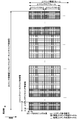
- FIG. 2 is a diagram illustrating an example of an uplink radio frame configuration according to the first embodiment. It is a figure which shows an example of the block configuration of the base station apparatus which concerns on 1st Embodiment. It is a figure which shows an example of the block configuration of the terminal device which concerns on 1st Embodiment.
- a first embodiment of the present invention will be described below.
- a base station apparatus base station, Node B, eNB (EUTRAN NodeB)
- a terminal apparatus terminal, mobile station, user apparatus, UE (User equipment)
- UE User equipment
- a channel means a medium used for signal transmission
- a physical channel means a physical medium used for signal transmission.
- a physical channel can be used synonymously with a signal.
- the physical channel may be added in the future in EUTRA and A-EUTRA, or the structure and format of the physical channel may be changed or added. Even when the physical channel is changed or added, the description of each embodiment of the present invention will be given. Does not affect.
- Radio frames In EUTRA and A-EUTRA, scheduling of physical channels or physical signals is managed using radio frames.
- One radio frame is 10 ms, and one radio frame is composed of 10 subframes. Further, one subframe is composed of two slots (that is, one subframe is 1 ms, and one slot is 0.5 ms).
- resource blocks are used as a minimum scheduling unit in which physical channels are allocated.
- a resource block is defined by a constant frequency region composed of a set of a plurality of subcarriers (for example, 12 subcarriers) and a region composed of a constant transmission time interval (1 slot) on the frequency axis.
- the guard period is not received by the terminal device by not receiving the tail part (the last symbol) of the downlink subframe immediately before the uplink subframe from the same terminal device. Generated.
- the guard period referred to as the HD guard subframe, is the same by not receiving the downlink subframe immediately before the uplink subframe from the same terminal equipment, and the same It is generated by the terminal device by not receiving the downlink subframe immediately after the uplink subframe from the terminal device. That is, in the HD-FDD operation, the terminal apparatus generates a guard period by controlling the downlink subframe reception process.
- TDD can be applied to frame structure type 2.
- Each radio frame is composed of two half frames. Each half frame is composed of five subframes.
- the UL-DL configuration in a cell may change between radio frames, and control of subframes in uplink or downlink transmission may occur in the latest radio frame.
- the UL-DL configuration in the latest radio frame can be obtained via PDCCH or higher layer signaling.
- the UL-DL setting indicates the configuration of an uplink subframe, a downlink subframe, and a special subframe in TDD.
- the special subframe includes DwPTS capable of downlink transmission, guard period (GP), and UpPTS capable of uplink transmission.
- the configurations of DwPTS and UpPTS in the special subframe are managed in a table, and the terminal device can acquire the configuration via higher layer signaling.
- the special subframe is a switching point from the downlink to the uplink.
- a communication device terminal device and / or base station device, device, module
- the number and function of the units may be limited.
- RF Radio Frequency
- IF Intermediate Frequency
- SC-FDMA Single Carrier-Frequency Division Multiple Access
- OFDM Orthogonal Downlink Physical Downlink Physical Downlink Physical Downlink Physical Downlink Physical Downlink Physical Downlink Physical Downlink Physical Downlink Physical Downlink Physical Downlink Physical Downlink Physical Downlink Physical Downlink Physical Downlink Physical Downlink Physical Downlink Physical Downlink Physical Downlink Physical Downlink Physical Downlink Physical Downlink Physical Downlink Physical Downlink Physical Downlink Physical Downlink Physical Downlink Physical Downlink Physical Downlink Physical Downlink Physical Downlink subframe generator used in transmitter and receiver
- the bandwidth supported by the part or the like may be limited (for example, 1.4 MHz).
- the power class / power value may be lower than that of the conventional transmission unit or reception unit due to the limited performance of the amplifier used in the transmission unit or reception unit. That is, the communicable range (coverage) of a communication device that implements machine type communication may be narrower than that of a conventional communication device.
- the number of antennas (antenna ports) provided in the transmission unit and the reception unit may be limited. That is, the function of performing
- the terminal device used for machine type communication according to the present invention may be referred to as an MTC terminal or a low-complex terminal (LC terminal) in order to distinguish it from a terminal device such as a mobile phone.
- the terminal device includes an MTC terminal.
- the terminal device of the present invention may include an LC terminal.
- the terminal device of the present invention may include an extended coverage terminal (EC terminal).
- the communication apparatus according to the present invention may have a function of supporting coverage extension in order to ensure a communicable range or communication quality. That is, the terminal device of the present invention may be referred to as an extended coverage terminal.
- the terminal device of the present invention may be referred to as a low complexity terminal.
- the MTC terminal may be referred to as an LC terminal or an EC terminal. That is, the MTC terminal may include an LC terminal or an EC terminal. However, the LC terminal and the EC terminal may be distinguished as different types / categories.
- a terminal that supports LTE communication technology / service may be referred to as an LTE terminal.
- the MTC terminal is a part of the LTE terminal, but is a low-cost and low-complex terminal as compared with the conventional LTE terminal. That is, the MTC terminal is an LTE terminal specialized / limited to a specific function.
- a conventional LTE terminal is simply referred to as an LTE terminal.
- LC terminals are targeted for low-end (eg, low average sales per user, low data rate, delay tolerant) applications such as MTC.
- the LC terminal shows terminal category 0, and the performance regarding transmission and reception is inferior compared with the terminals of other categories.
- the LC terminal may be referred to as a category 0 terminal.
- the LC terminal basically includes a low-end model terminal, but the EC terminal may include both a low-end model and a high-end model.
- EC-related functions may be used not only in category 0 but also in other categories of terminals.
- the LC terminal may access only the cell indicated by the SIB1 that supports LC terminal access. If the cell does not support the LC terminal, the LC terminal considers that cell access prohibited.
- the base station apparatus determines that the terminal apparatus is an LC device based on LCID (Logical Channel ID) for CCCH (Common Control Channel) and function information (performance information) of the terminal apparatus.
- LCID Logical Channel ID
- CCCH Common Control Channel
- performance information performance information
- S1 signaling is expanded to include terminal radio function information for paging.
- the MME Mobility Management Entity
- the MME uses this information to instruct the base station apparatus that the paging request from the MME relates to the LC terminal.
- EC terminals are intended to expand coverage and / or improve communication quality within the coverage. For example, it is assumed that the EC terminal communicates in a place where the communication environment is poor, such as a basement.
- the terminal device function information (UE radio access capability, UE UEEUcapability) starts the procedure for the terminal device in the connection mode when the base station device (EUTRAN) needs the function information of the terminal device.
- the base station apparatus inquires about the function information of the terminal apparatus, and transmits the function information of the terminal apparatus in response to the inquiry.
- the base station apparatus determines whether or not the function information is supported, and if so, transmits the setting information corresponding to the function information to the terminal apparatus using higher layer signaling or the like.
- the terminal device determines that transmission / reception based on the function is possible.
- FIG. 1 is a diagram illustrating an example of a downlink radio frame configuration according to the present embodiment.
- An OFDM access scheme is used for the downlink.
- a physical downlink control channel (PDCCH), an extended physical downlink control channel (EPDCCH), a physical downlink shared channel (PDSCH), and the like are allocated.
- the downlink radio frame is composed of a downlink resource block (RB) pair.
- One downlink RB pair is composed of two downlink RBs (RB bandwidth ⁇ slot) that are continuous in the time domain.
- One downlink RB is composed of 12 subcarriers in the frequency domain.
- NCP PNormal CP
- ECP Extended CP
- OFDM symbols A region defined by one subcarrier in the frequency domain and one OFDM symbol in the time domain is referred to as a resource element (RE).
- PDCCH / EPDCCH is a physical channel through which downlink control information (DCI) such as a terminal device identifier, PDSCH scheduling information, PUSCH scheduling information, modulation scheme, coding rate, and retransmission parameter is transmitted.
- DCI downlink control information
- a downlink sub-frame is prescribed
- a downlink sub-frame is substantially synchronized between CC.
- a synchronization signal (SS), a physical broadcast channel (PBCH), or a downlink reference signal (DLRS) may be arranged in the downlink subframe.
- DLRS includes cell-specific reference signal (CRS) transmitted on the same antenna port (transmission port) as PDCCH, channel state information reference signal (CSI-RS) used for measurement of channel state information (CSI),
- CRS cell-specific reference signal
- CSI-RS channel state information reference signal
- UERS terminal-specific reference signal
- DMRS demodulation reference signal
- a part of the CRS antenna ports are used as time and / or frequency tracking signals. Only) or a signal similar to a signal corresponding to all antenna ports (referred to as an extended synchronization signal) can be inserted.
- the antenna port may be referred to as a transmission port.
- “physical channel / physical signal is transmitted through an antenna port” includes the meaning that a physical channel / physical signal is transmitted using a radio resource or layer corresponding to the antenna port.
- the reception unit means receiving a physical channel or a physical signal from a radio resource or layer corresponding to the antenna port.
- FIG. 2 is a diagram illustrating an example of an uplink radio frame configuration according to the present embodiment.
- the SC-FDMA scheme is used for the uplink.
- a physical uplink shared channel (PUSCH), a physical uplink control channel (PUCCH), and the like are allocated.
- an uplink reference signal is assigned together with PUSCH and PUCCH.
- the uplink radio frame is composed of uplink RB pairs.
- One uplink RB pair is composed of two uplink RBs (RB bandwidth ⁇ slot) that are continuous in the time domain.
- One uplink RB is composed of 12 subcarriers in the frequency domain. In the time domain, 7 SC-FDMA symbols are added when a normal cyclic prefix (Normal CP) is added and 6 cyclic prefixes (Extended CP) longer than normal are added. Composed.
- Normal CP normal cyclic prefix
- Extended CP Extended cyclic prefix
- the synchronization signal is composed of three types of primary synchronization signals (PSS) and secondary synchronization signals (SSS) composed of 31 types of codes arranged alternately in the frequency domain. 504 kinds of cell identifiers (physical cell ID (PCI)) for identifying a station apparatus and frame timing for radio synchronization are shown.
- PCI physical cell ID
- the terminal device specifies the physical cell ID of the synchronization signal received by the cell search.
- the physical broadcast channel is used to notify (set) control parameters (broadcast information, system information (SI)) that are commonly used by terminal devices in a cell.
- a radio resource in which broadcast information is transmitted on the PDCCH is notified to a terminal device in the cell, and broadcast information that is not notified on the PBCH is a layer 3 message (system information) that notifies the broadcast information on the notified radio resource on the PDSCH. ) Is sent.
- the TTI (repetition rate) of the PBCH to which BCH (Broadcast Channel) is mapped is 40 ms.
- PBCH is allocated using 6 RBs (that is, 72 REs) at the center of the transmission bandwidth.
- the number of PBCH antenna ports is the same as the number of CRS antenna ports.
- PDSCH is not transmitted with resources overlapping with PBCH and CRS. That is, the terminal device does not expect that PDSCH is mapped to the same resource as PBCH and CRS. Also, the base station apparatus does not map PDSCH to the same resource as PBCH or CRS.
- PBCH is used to notify system control information (master information block (MIB)).
- MIB master information block
- MIB contains system information transmitted on BCH.
- the system information included in the MIB includes a downlink transmission bandwidth, a PHICH setting, and a system frame number.
- the MIB includes 10 spare bits (bit string).
- the downlink transmission bandwidth may be included in the mobility control information.
- the mobility control information may be included in information related to RRC connection reconfiguration. That is, the downlink transmission bandwidth may be set via the RRC message / upper layer signaling.
- SIB System information transmitted outside the MIB is transmitted in a system information block (SIB).
- SI message system information message
- All SIBs included in the SI message are transmitted in the same cycle.
- all SIBs are transmitted on DL-SCH (Downlink Shared Channel).
- the DL-SCH may be referred to as DL-SCH data or DL-SCH transport block.
- the resource allocation of the PDSCH in which the DL-SCH to which the SI message is mapped is transmitted is indicated using a PDCCH with a CRC scrambled by the SI-RNTI.
- the resource allocation of the PDSCH to which the DL-SCH to which information on the random access response is mapped is transmitted is indicated by using the PDCCH with the CRC scrambled by the RA-RNTI.
- PCH may be referred to as PCH data or a PCH transport block.
- SIB has different system information that can be sent for each type. That is, the information shown for each type is different.
- SIB1 system information block type 1
- SIB1 includes information related to estimation (evaluation, measurement) when a terminal device accesses a certain cell, and defines scheduling of other system information.
- SIB1 is information related to cell access such as PLMN identifier list, cell identifier, CSG identifier, cell selection information, maximum power value (P-Max), frequency band indicator, SI window length, transmission cycle for SI message, Includes TDD settings.
- the terminal device Upon receiving SIB1 via broadcast or via dedicated signaling, the terminal device shall be in idle mode or connected mode while T311 is activated, and the terminal device is a category 0 terminal. If there is, and SIB1 does not include information (category0Allowed) indicating that category 0 terminals are allowed to access the cell, it is considered that access to the cell is prohibited. . That is, a category 0 terminal cannot access a cell if the category 0 terminal is not permitted to access the cell in SIB1.
- SIB2 system information block type 2
- SIB2 includes radio resource setting information common to all terminal apparatuses.
- SIB2 includes frequency information such as an uplink carrier frequency and an uplink bandwidth, information on a time adjustment timer, and the like.
- the SIB2 includes information related to physical channel / physical signal settings such as PDSCH, PRACH, SRS, and uplink CP length. Further, SIB2 includes information related to the setting of higher layer signaling such as RACH and BCCH.
- SIB3 system information block type 3
- SIB3 includes information common to cell reselection within a frequency, between frequencies, and between RAT (Radio Access Technology).
- 17 types of SIBs are prepared, but may be newly added / defined depending on the application.
- the SI message includes SIBs other than SIB1.
- the MTC terminal receives the PDCCH for the MTC terminal based on the information.
- the information may include a resource block index (frequency position) to which a PDCCH for the MTC terminal for the transmission bandwidth is allocated.
- the information may also include an index indicating the start position (start position, start symbol) of the OFDM symbol to which the PDCCH for the MTC terminal is assigned.
- the information may include the number of OFDM symbols necessary for PDCCH for the MTC terminal.
- encoded BCH transport blocks are mapped in 4 subframes within a 40 ms interval.
- the 40 ms timing of PBCH is blind detected. That is, there is no explicit signaling to indicate 40 ms timing.
- Each subframe is assumed to be capable of self-decoding. That is, the BCH is assumed to be a fairly good channel condition and can be decoded in a single reception.
- MIB (or PBCH) uses a fixed schedule that repeats within 40 ms with a period of 40 ms.
- SFN is synonymous with a radio frame number.
- the base station device When the base station device (PLMN, EUTRA) indicates that the terminal device supports the function related to MTC (the function related to LC (Low Mobility), the function related to Enhanced Enhanced Coverage (EC)) using the function information. If the access of the MTC terminal can be permitted (has a cell that can permit the access of the MTC terminal), information on the setting of the physical channel (PDCCH / EPDCCH, PDSCH, PHICH, PBCH, etc.) for the MTC terminal in the spare bit of the MIB / The parameter may be set and the MIB may be transmitted. Note that the base station apparatus may provide an accessible cell to the MTC terminal using higher layer signaling.
- the base station apparatus may be configured to repeatedly transmit MIB (PBCH) transmission to the MTC terminal not only in the above-described subframe and radio frame but also in a shorter cycle.
- PBCH MIB
- the PBCH for the MTC terminal may be transmitted in the MBSFN subframe.
- the MIB for the MTC terminal may be transmitted in a measurement gap subframe.
- the reception accuracy may be improved by repeatedly receiving more in the MTC terminal.
- the scrambling sequence generator is initialized using an initial value (parameter) during repeated transmission or reception. Therefore, the scrambling sequence generator in such a PBCH has a longer period. It may be initialized. That is, the number of receptions of PBCH corresponding to the MIB increases, but the timing for initializing the scrambling sequence generator may be adjusted according to the number of repetitions.
- a terminal device that does not support simultaneous transmission / reception does not expect to be able to receive a downlink signal in a downlink subframe or a special subframe.
- a terminal device that does not support simultaneous transmission / reception does not expect to be able to transmit an uplink signal in an uplink subframe or a special subframe.
- the MTC terminal can monitor the PBCH for the MTC terminal based on the setting.
- the system information transmitted by this PBCH includes information on PHICH / EPHIICH (Enhanced (PHICH) settings for MTC terminals, information on settings of other physical channels, carrier frequency for MTC terminals, downlink transmission bandwidth for MTC terminals, and / Or uplink transmission bandwidth may be included.
- the base station apparatus may schedule the radio resource allocated to the MTC terminal so as not to allocate the radio resource to the LTE terminal. That is, the base station apparatus may perform scheduling so that FDM is performed between the MTC terminal and the LTE terminal.
- Information indicating whether various physical channel settings for the MTC terminal are set in the SIB or RRC message may be set in the MIB spare bit. For example, when the PDCCH / EPDCCH setting for the MTC terminal is set in the SIB or RRC message, the value of the corresponding spare bit is set to “1”. When the PDCCH / EPDCCH setting for the MTC terminal is not set in the SIB or RRC message, the value of the corresponding spare bit is set to “0”. Similarly, when the PDSCH setting for the MTC terminal is set in the SIB or RRC message, the value of the corresponding spare bit is set to “1”.
- the value of the corresponding spare bit is set to “0”.
- PBCH BCCH
- PHICH PHICH
- PRACH RACH
- PUSCH PUCCH
- PCCH Paging Control Channel
- CCCH Common Control ⁇ ⁇ Channel
- the MTC terminal may read the value of the corresponding bit, acquire the setting information from the corresponding SIB or RRC message, and perform transmission and reception of the corresponding signal.
- radio resource allocation information (resource setting, subframe setting, transmission bandwidth, start symbol, etc.) accessible by the MTC terminal may be set.
- the MTC terminal can receive PBCH (second PBCH) and PDCCH (second PDCCH or EPDCCH) for the MTC terminal.
- the PHICH setting corresponding to the PDCCH may be set in the system information corresponding to the PBCH.
- Various RNTI values may be set in the system information.
- the MTC terminal can acquire information related to various physical channel / physical signal settings for the MTC terminal.
- the information regarding these settings may include the number of repetitions.
- the information related to these settings may include information related to the power class.
- the information regarding these settings may include the value of each RNTI.
- the downlink transmission bandwidth for the MTC terminal and the start symbol of the second PDCCH / EPDCCH may be indicated.
- the MTC terminal can receive the second PDCCH / EPDCCH based on the downlink transmission bandwidth and the start symbol. Further, if there is a CRC scrambled by SI-RNTI in the second PDCCH / EPDCCH, an SIB (SI message) for the MTC terminal can be detected. Information regarding the setting of the physical channel / physical signal indicated in the SIB is the physical channel / physical signal corresponding to the MTC terminal.
- the MTC terminal can transmit / receive a physical channel / physical signal based on the set information. If there is a CRC scrambled by P-RNTI in the second PDCCH / EPDCCH, the PCH for the MTC terminal can be detected. In such a case, SI-RNTI and P-RNTI may be predetermined values.
- the base station apparatus sets the setting information for the MTC terminal in the MIB spare bits, thereby making the information related to the setting of various physical channels / physical signals for the MTC terminal different from the LTE terminal. It can be set using radio resources.
- SIB1 uses a fixed schedule that repeats within 80 ms with a period of 80 ms.
- the SI message is transmitted in a time domain window (SI window) that is periodically generated using dynamic scheduling (PDCCH scheduling, PDCCH with CRC scrambled SI-RNTI (System Information Radio Network Temporary Identifier)).
- SI window time domain window
- SI windows of different SI messages do not overlap. Only one corresponding SI is transmitted within one SI window.
- the length of the SI window is common to all SI messages and can be set.
- MBSFN Multimedia Broadcast multicast service Single Frequency Network
- the terminal device captures detailed time domain scheduling (and other information such as frequency domain scheduling and transport format used) by decoding the PDCCH SI-RNTI.
- the SI message includes SIBs other than SIB1.
- the base station device indicates that the terminal device supports the function related to MTC (the function related to LC (Low Mobility), the function related to Enhanced Enhanced Coverage (EC)) using the function information.
- MTC the function related to LC (Low Mobility), the function related to Enhanced Enhanced Coverage (EC)
- EC Enhanced Enhanced Coverage
- the access of the MTC terminal can be permitted (has a cell that can permit the access of the MTC terminal), the physical channel (PDCCH / EPDCCH, PDSCH, PHICH, etc.) for the MTC terminal in the SIB (either SIB1 or SI message) It is also possible to set information / parameters related to the setting and transmit the SIB.
- the base station apparatus may be configured to repeatedly transmit the SIB (SIB1, SI message, new SIB type) to the MTC terminal in a shorter cycle than the above-described subframe and radio frame.
- SIB SIB1, SI message, new SIB type
- the SIB for the MTC terminal may be transmitted in the MBSFN subframe.
- the SIB for the MTC terminal may be transmitted in a subframe of the measurement gap.
- the reception accuracy may be improved by repeatedly receiving more in the MTC terminal. Since it is not preferable that the scrambling sequence generator is initialized based on the initial value (parameter) in the middle of repeated transmission or reception, the PDCCH and PDSCH corresponding to such SIB are not scrambled in such PDCCH or PDSCH.
- the ring sequence generator may be initialized with a longer period. That is, the number of receptions of PDCCH and PDSCH corresponding to SIB increases, but the timing for initializing the scrambling sequence generator may be adjusted using the initial value according to the number of repetitions.
- the scrambling used for the downlink signals may be performed at a timing different from the conventional timing.
- the initial value (parameter) used for initialization of the scrambling sequence or pseudo-random sequence generator used for the downlink signal may be set using higher layer signaling, system information, or MIB.
- the initial value used for initialization of the generator is determined based on PCI, slot number, etc., but is determined using a higher layer parameter or a predetermined value (for example, RNTI value) different from that. Also good.
- the scrambling used for the uplink signals may be performed at a timing different from the conventional timing.
- the initial value (parameter) used for initialization of the scrambling sequence or pseudo-random sequence generator used for the uplink signal may be set using higher layer signaling, system information, or MIB.
- the initial value used for initialization of the generator is determined based on PCI, slot number, etc., but is determined using a higher layer parameter or a predetermined value (for example, RNTI value) different from that. Also good.
- the RNTI that scrambles the CRC includes RA-RNTI, C-RNTI, SPS C-RNTI, temporary C-RNTI, eIMTA-RNTI, TPC-PUCCH-RNTI, TPC-PUSCH-RNTI, M-RNTI, P-RNTI, There is SI-RNTI.
- RA-RNTI, C-RNTI, SPS C-RNTI, eIMTA-RNTI, TPC-PUCCH-RNTI, and TPC-PUSCH-RNTI are configured through higher layer signaling.
- M-RNTI, P-RNTI, and SI-RNTI correspond to one value.
- P-RNTI corresponds to PCH and PCCH and is used to notify changes in paging and system information.
- SI-RNTI corresponds to DL-SCH and BCCH and is used for reporting system information.
- RA-RNTI corresponds to DL-SCH and is used for a random access response.
- RA-RNTI, C-RNTI, SPS C-RNTI, temporary C-RNTI, eIMTA-RNTI, TPC-PUCCH-RNTI, and TPC-PUSCH-RNTI are set using higher layer signaling. Predetermined values are defined for M-RNTI, P-RNTI, and SI-RNTI.
- the PDCCH with CRC scrambled by each RNTI may have a different transport channel or logical channel depending on the value of the RNTI. That is, the information shown may differ depending on the value of RNTI.
- SI-RNTI One SI-RNTI is used to address SIB1, as with all SI messages.
- the terminal device applies the system information capturing procedure to capture the AS and NAS system information broadcast by EUTRAN. This procedure is applied to a terminal device in an idle mode (idle state, RRC_IDLE) and a connection mode (connected state, RRC_CONNECTED).
- the terminal device must have a valid version of the necessary system information.
- SIB8 system information block type 8 (SIB8) that depends on the support of the relevant RAT or system information block type that depends on support of WLAN (Wireless Local Area Network) interworking assisted by RAN (Radio Access Network) 17, not only SIB2 but also MIB and SIB1 are required.
- WLAN Wireless Local Area Network
- RAN Radio Access Network
- MIB, SIB1, SIB2, and SIB17 are required.
- the terminal device deletes the system information three hours after confirming that the stored system information is valid.
- the terminal device If the terminal device is different from one of the system information holding the system information value tag included in the SIB1, the system information block type 10 (SIB10), the system information block type 11 (SIB11), and the system information block type 12 ( The stored system information except SIB12) and system information block type 14 (SIB14) is regarded as invalid.
- the terminal device is in the connection mode when the RRC connection is established.
- the terminal device is in the idle mode when the RRC connection is not established.
- DRX specific to the terminal device may be set by an upper layer. Further, mobility is controlled in the terminal device in the idle mode. Also, the terminal device in the idle mode changes the PCH in order to detect an incoming call or change of system information, an ETWS notification for a terminal device capable of ETWS, and a CMAS notification for a terminal device capable of CMAS. Monitor. Also, the terminal device in the idle mode performs neighboring cell measurement and cell (re) selection. The terminal device in the idle mode captures system information. Also, the terminal device in the idle mode records the available measurement with the location and time for the terminal device for which the recorded measurement is set.
- the terminal device in the connection mode transmits unicast data from / to the terminal device.
- the terminal device in the connection mode may set DRX specific to the terminal device.
- one or more SCells aggregated with PCells are used to expand the bandwidth.
- one SCG (Secondary Cell Group) that is aggregated with MCG (Master Cell Group) is used to expand the bandwidth.
- the mobility of the terminal device in the connection mode is controlled in the network.
- the terminal device in the connection mode can change the system information, PCH and / or SIB1 content in order to detect ETWS notification for terminal devices capable of ETWS and CMAS notification for terminal devices capable of CMAS. To monitor.
- the terminal device in the connection mode also monitors the control channel associated with the shared data channel to determine if data is scheduled. Further, the terminal device in the connection mode provides channel quality and feedback information. The terminal device in the connection mode performs neighboring cell measurement and measurement report. Further, the terminal device in the connection mode captures system information.
- the PBCH is assigned to the center 6 RBs (72 REs) in the downlink bandwidth setting in the frequency domain, and in the time domain, slot 1 of subframe 0 (first subframe in the radio frame, subframe index 0). Assigned to indexes (OFDM symbol indexes) 0 to 3 of (second slot in subframe, slot index 1).
- the downlink bandwidth setting is represented by a multiple of the resource block size in the frequency domain, represented by the number of subcarriers.
- the downlink bandwidth setting is a downlink transmission bandwidth set in a certain cell. That is, PBCH is transmitted using 6 RBs at the center of the downlink transmission bandwidth.
- PBCH is not transmitted using resources reserved for DLRS. That is, the PBCH is mapped avoiding DLRS resources.
- the PBCH mapping is performed assuming CRS for the existing antenna ports 0 to 3 regardless of the actual setting. Also, the CRS resource elements of antenna ports 0 to 3 are not used for PDSCH transmission.
- CGI cell global identifier
- TAI tracking area identifier
- random access setting information such as a transmission timing timer
- common radio resource setting information in the cell Neighboring cell information, uplink access restriction information, etc.
- the downlink reference signal is classified into a plurality of types depending on its use.
- the CRS is a pilot signal transmitted at a predetermined power for each cell, and is a downlink reference signal that is periodically repeated in the frequency domain and the time domain based on a predetermined rule.
- the terminal device measures reception quality (RSRP (Reference Signal Received Power), RSRQ (Reference Signal Received Quality)) for each cell by receiving the CRS.
- the terminal apparatus also uses the CRS as a PDCCH transmitted simultaneously with the CRS or a reference signal for demodulating the PDSCH.
- a sequence used for CRS a sequence identifiable for each cell is used.
- DLRS is also used for estimation of downlink propagation path fluctuation (channel estimation).
- the DLRS used for estimating the channel fluctuation is referred to as a channel state information reference signal (CSI-RS).
- CSI-RS channel state information reference signal
- UERS DLRS individually set for a terminal device
- DMRS DMRS
- Dedicated RS DLRS individually set for a terminal device
- the channel state information includes a reception quality indicator (CQI), a precoding matrix indicator (PMI), a precoding type indicator (PTI), and a rank indicator (RI), respectively, and a suitable modulation scheme and coding rate, It can be used to specify (represent) a suitable precoding matrix, a suitable PMI type, and a suitable rank.
- CQI reception quality indicator
- PMI precoding matrix indicator
- PTI precoding type indicator
- RI rank indicator
- Each indicator may be written as Indication.
- wideband CQI and PMI assuming transmission using all resource blocks in one cell and some continuous resource blocks (subbands) in one cell were used. It is classified into subband CQI and PMI assuming transmission.
- the PMI uses one type of suitable PMI, ie, the first PMI and the second PMI. There is a type of PMI that represents a recording matrix. CSI is reported using PUCCH or PUSCH.
- the physical downlink control channel (PDCCH) is transmitted with several OFDM symbols (for example, 1 to 4 OFDM symbols) from the top of each subframe.
- the extended physical downlink control channel (EPDCCH) is a PDCCH arranged in an OFDM symbol in which the PDSCH is arranged.
- the PDCCH or EPDCCH is used for the purpose of notifying the terminal apparatus of radio resource allocation information according to the scheduling of the base station apparatus, information for instructing an adjustment amount for increase / decrease of transmission power, and other control information. That is, the PDCCH / EPDCCH is used to transmit DCI (or a certain DCI format composed of at least one DCI). In each embodiment of the present invention, when only PDCCH is described, it means both PDCCH and EPDCCH physical channels unless otherwise specified.
- the PDCCH is used to notify the terminal apparatus (UE) and the relay station apparatus (RN) of the PCH (Paging Channel) and DL-SCH resource allocation and the HARQ information (DL HARQ) regarding the DL-SCH.
- the PDCCH is used to transmit an uplink scheduling grant and a side link scheduling grant.
- the EPDCCH is used for notifying the terminal apparatus (UE) of DL-SCH resource allocation and HARQ information related to the DL-SCH. Moreover, EPDCCH is used in order to transmit an uplink scheduling grant and a side link scheduling grant.
- PDCCH is transmitted by aggregating one or several consecutive control channel elements (CCEs).
- CCE control channel elements
- One CCE corresponds to nine resource element groups (REG).
- the number of CCEs available in the system is determined excluding the physical control format indicator channel (PCFICH) and the physical HARQ indicator channel (PHICH).
- the PDCCH supports a plurality of formats (PDCCH format).
- Each PDCCH format defines the number of CCEs, the number of REGs, and the number of PDCCH bits.
- One REG is composed of 4 REs. That is, up to 3 REGs may be included in 1 PRB.
- the PDCCH format is determined according to the size of the DCI format.
- the terminal device Since a plurality of PDCCHs are mapped to the entire downlink transmission bandwidth, the terminal device continues decoding until it detects a PDCCH addressed to itself. That is, the PDCCH cannot be detected even if only a part of the frequency region is received and decoded.
- PDCCHs may be transmitted in one subframe.
- PDCCH is transmitted through the same set of antenna ports as PBCH.
- EPDCCH is transmitted from an antenna port different from PDCCH.
- the terminal apparatus Before transmitting / receiving layer 2 messages and layer 3 messages (paging, handover command, etc.) that are downlink data and higher layer control information, the terminal apparatus monitors (monitors) the PDCCH addressed to itself and By receiving the PDCCH, it is necessary to acquire radio resource allocation information called an uplink grant during transmission and a downlink grant (downlink assignment) during reception from the PDCCH.
- the PDCCH may be configured to be transmitted in the resource block area individually allocated from the base station apparatus to the terminal apparatus, in addition to the above-described OFDM symbol.
- DCI is transmitted in a specific format.
- the formats indicating the uplink grant and the downlink grant are transmitted in different formats.
- the terminal device can acquire an uplink grant from DCI format 0 and can acquire a downlink grant from DCI format 1A.
- DCI format 3 / 3A including only DCI indicating a transmission power control command for PUSCH or PUCCH
- DCI format 1C DCI format 1C
- radio resource allocation information for PUSCH and PDSCH is a kind of DCI.
- the terminal device can set various parameters of the corresponding uplink signal and downlink signal based on the detected DCI (value set in the detected DCI) and perform transmission / reception. For example, when DCI related to PUSCH resource allocation is detected, the terminal apparatus can perform PUSCH resource allocation based on the DCI and transmit the DCSCH. Further, when a transmission power control command (TPC command) for the PUSCH is detected, the terminal device can adjust the transmission power of the PUSCH based on the DCI. Further, when DCI related to PDSCH resource allocation is detected, the terminal apparatus can receive PDSCH from the resource indicated based on the DCI.
- TPC command transmission power control command
- the terminal device can acquire (discriminate) various DCIs (DCI format) by decoding a PDCCH accompanied by a CRC (Cyclic Redundancy Check) scrambled by a specific RNTI (Radio Network Temporary Identifier). Which RNTI scrambles the PDCCH with CRC scrambled is set by higher layers.
- DCI format DCI format
- CRC Cyclic Redundancy Check
- RNTI Radio Network Temporary Identifier
- the control information transmitted on the DL-SCH or PCH corresponding to the PDCCH differs depending on which RNTI is used for scrambling. For example, when scrambled by P-RNTI (PagingPRNTI), information related to paging is transmitted by the PCH. Further, when scrambled by SI-RNTI (System Information Information RNTI), system information may be transmitted using the DL-SCH.
- P-RNTI PagingPRNTI
- SI-RNTI System Information Information RNTI
- the DCI format is mapped to a search space (shared search space (CSS), UE specific search space (UESS)) given by a specific RNTI.
- the search space is defined as a set of PDCCH candidates to be monitored. That is, in each embodiment of the present invention, monitoring the search space is synonymous with monitoring the PDCCH.
- CSS and UESS in PCell may overlap. Only EPESS may be defined in EPDCCH.
- PHICH is used to transmit HARQ-ACK / NACK (NAK) in response to uplink transmission.
- PCFICH is used to notify the terminal apparatus and the relay station apparatus regarding the number of OFDM symbols used for PDCCH.
- PCFICH is transmitted for each downlink subframe or special subframe.
- the physical downlink shared channel is a terminal device that uses downlink data (DL-SCH data, DL-SCH transport block) as well as broadcast information (system information) not notified by PCH, paging or PBCH as a layer 3 message. Used to notify The radio resource allocation information of PDSCH is indicated using PDCCH.
- the PDSCH is transmitted after being arranged in an OFDM symbol other than the OFDM symbol through which the PDCCH is transmitted. That is, PDSCH and PDCCH are time division multiplexed (TDM) within one subframe. However, PDSCH and EPDCCH are frequency division multiplexed (FDM) within one subframe.
- PDSCH may be used to broadcast system control information.
- the PDSCH may be used as paging when the network does not know the location cell of the terminal device. That is, PDSCH may be used to transmit paging information or system information change notification.
- the PDSCH may be used to transmit control information between the terminal device and the network to a terminal device (an idle mode terminal device) that does not have an RRC connection with the network.
- PDSCH may be used to transmit dedicated control information between the terminal device and the network to the terminal device having RRC connection (terminal device in connection mode).
- the physical uplink control channel is a downlink data reception confirmation response (HARQ-ACK; Hybrid Automatic Repeat reQuest-Acknowledgement or ACK / NACK (or ACK / NAK) or Acknowledgement / NegativeAntegment / Negemgent). It is used for downlink channel (channel state) information (CSI) reporting and uplink radio resource allocation request (radio resource request, scheduling request (SR)). That is, the PUCCH is used to transmit HARQ-ACK / NACK, SR, and CSI reports that respond to downlink transmission.
- the PUCCH supports a plurality of formats according to the type of uplink control information (UCI) such as HARQ-ACK, CSI, and SR to be transmitted.
- UCI uplink control information
- PUCCH For PUCCH, a resource allocation method and a transmission power control method are defined for each format. PUCCH uses 1 RB in each of two slots of one subframe. That is, PUCCH is composed of 1 RB regardless of the format. Moreover, PUCCH does not need to be transmitted by UpPTS of a special subframe.
- the PUCCH When the PUCCH is transmitted in the SRS subframe, in the PUCCH format to which the shortened format is applied (for example, formats 1, 1a, 1b, 3), the last one symbol or 2 to which the SRS may be allocated. The symbol (one or two symbols at the end of the second slot in the subframe) is emptied.
- the PUCCH format to which the shortened format is applied for example, formats 1, 1a, 1b, 3
- the last one symbol or 2 to which the SRS may be allocated.
- the symbol one or two symbols at the end of the second slot in the subframe
- 1RB of each slot may support a mix of PUCCH format 1 / 1a / 1b and PUCCH format 2 / 2a / 2b. That is, the terminal apparatus may transmit the PUCCH format 1 / 1a / 1b and the PUCCH format 2 / 2a / 2b with 1 RB.
- the pseudo random sequence generator may not be initialized using the initial value until the repeated transmission of the PUCCH is completed.
- the physical uplink shared channel mainly transmits uplink data (UL-SCH data, UL-SCH transport block) and control data, and uplinks such as CSI, ACK / NACK (HARQ-ACK), and SR. It is also possible to include link control information (UCI). In addition to uplink data, it is also used to notify the base station apparatus of layer 2 messages and layer 3 messages, which are higher layer control information. Similarly to the downlink, PUSCH radio resource allocation information is indicated by PDCCH (PDCCH with DCI format).
- PDCCH PDCCH with DCI format
- the last one symbol or two symbols to which the SRS may be allocated (the last slot in the second slot in the subframe) 1 symbol or 2 symbols of the tail) is emptied.
- the scrambling sequence generator does not have to be initialized using the initial value until the repeated transmission of the PUSCH is completed.
- the uplink reference signal (uplink pilot signal, uplink pilot channel, ULRS) is mainly divided into a demodulation reference signal (DMRS) used by the base station apparatus to demodulate PUCCH and / or PUSCH, and a base station apparatus.
- DMRS demodulation reference signal
- SRS sounding reference signal
- the SRS includes a periodic sounding reference signal (P-SRS) transmitted periodically and an aperiodic sounding reference signal (A-SRS) transmitted when instructed by the base station apparatus.
- P-SRS is called trigger type 0 SRS
- A-SRS is called trigger type 1 SRS.
- the SRS is assigned to the last symbol of the subframe with one symbol or two symbols.
- a subframe in which SRS is transmitted may be referred to as an SRS subframe.
- the SRS subframe is determined based on a cell-specific subframe setting and a terminal device-specific subframe setting.
- all terminal apparatuses in the cell do not allocate a PUSCH resource to the last symbol of the subframe.
- the PUCCH if the shortened format is applied, the PUCCH resource is not allocated to the last symbol of the subframe in the subframe set to the cell-specific subframe setting.
- the shortened format may not be applied depending on the PUCCH format.
- PUCCH may be transmitted in a normal format (that is, PUCCH resources are allocated to SRS symbols).
- PUCCH resources are allocated to SRS symbols.
- PRACH priority is given to transmission of PRACH. If the SRS symbol is on the PRACH guard time, the SRS may be transmitted.
- the physical random access channel is a channel used for notifying (setting) a preamble sequence and has a guard time.
- the preamble sequence is configured to notify information to the base station apparatus by a plurality of sequences. For example, when 64 types of sequences are prepared, 6-bit information can be indicated to the base station apparatus.
- PRACH is used as an access means (such as initial access) to a base station apparatus of a terminal apparatus.
- the PRACH is used for transmitting a random access preamble.
- the terminal apparatus transmits transmission timing adjustment information (timing advance (TA)) required for an uplink radio resource request when the PUCCH is not set for the SR or for matching the uplink transmission timing with the reception timing window of the base station apparatus.
- TA transmission timing adjustment information
- PRACH is used for requesting the base station apparatus (also called a command).
- the base station apparatus can request the terminal apparatus to start a random access procedure using the PDCCH (referred to as a PDCCH order).
- the layer 3 message is a message handled in the control plane (CP, C-Plane) protocol exchanged between the terminal device and the base station device in the RRC (Radio Resource Control) layer, and is synonymous with RRC signaling or RRC message. Can be used.
- a protocol that handles user data (uplink data and downlink data) with respect to the control plane is referred to as a user plane (UP, U-Plane).
- UP, U-Plane user plane
- the transport block that is transmission data in the physical layer includes a C-Plane message and U-Plane data in the upper layer. That is, in each embodiment of the present invention, data and transport block are synonymous. Detailed descriptions of other physical channels are omitted.
- the communicable range (communication area) of each frequency controlled by the base station apparatus is regarded as a cell.
- the communication area covered by the base station apparatus may have a different width and a different shape for each frequency.
- the area to cover may differ for every frequency.
- a wireless network in which cells having different types of base station apparatuses and different cell radii are mixed in the same frequency and / or different frequency areas to form one communication system is referred to as a heterogeneous network. .
- the terminal device is not connected to any network, such as immediately after turning on the power (for example, at startup). Such a disconnected state is referred to as an idle mode (RRC idle).
- the terminal device in the idle mode needs to be connected to one of the networks in order to perform communication. That is, the terminal device needs to be in a connection mode (RRC connection).
- the network may include a base station device, an access point, a network server, a modem, and the like belonging to the network.
- the terminal device in the idle mode needs to perform PLMN (Public Land Mobile Network) selection, cell selection / reselection, location registration, CSG (Closed Subscriber Group) cell manual selection, and the like.
- PLMN Public Land Mobile Network
- cell selection / reselection cell selection / reselection
- location registration location registration
- CSG Cell Subscriber Group
- the PLMN When the terminal device is turned on, the PLMN is selected by the non-access layer (NAS).
- the associated radio access technology (RAT) is set for the selected PLMN.
- the NAS provides a list of corresponding PLMNs, if available, that the access layer uses for cell selection / reselection.
- the terminal device searches for an appropriate cell of the selected PLMN and selects a cell (serving cell) in which an available service is provided. Further, the terminal device adjusts the frequency to the control channel. Such a selection is referred to as “camp to cell”.
- the terminal device uses the NAS registration procedure to detect the presence (selected cell) in the tracking area of the selected cell as a result of location registration success in which the selected PLMN becomes the registered PLMN. And information on tracking areas).
- the terminal device When the terminal device finds a more appropriate cell, it reselects the cell and camps according to the cell reselection criteria. If the new cell does not belong to at least one tracking area registered in the terminal device, location registration for the new cell is performed.
- the terminal device searches for a PLMN having a higher priority at regular time intervals, and searches for an appropriate cell if another PLMN is selected by the NAS.
- a search for available CSG may be triggered by the NAS to support manual CSG selection.
- the terminal device If the terminal device is out of the coverage range of the registered PLMN, either the new PLMN is automatically selected (automatic mode) or the PLMN is manually selected (manual mode). This may be set by the user. However, when receiving a service that does not require registration, the terminal device may not perform such registration.
- the terminal device can receive system information from PLMN (or EUTRAN).
- A2 When registered, if the terminal device attempts to establish an RRC connection, it performs initial access to the network using the control channel of the camped cell.
- the PLMN knows a set of tracking areas (that is, camp cells) in which the terminal device is camped. The PLMN can then send a “paging message” to the terminal equipment on the control channel of all cells in this set of tracking areas. Then, since the terminal device adjusts the frequency to the control channel of one cell in the registered tracking area, it can receive the paging message and respond to the control channel.
- a set of tracking areas that is, camp cells
- the terminal device can receive ETWS (Earthquake Tsunami Warning System) and CMAS (Commercial Mobile Alter System) notifications.
- ETWS Earthquake Tsunami Warning System
- CMAS Common Mobile Alter System
- the terminal device can receive MBMS (Multimedia Broadcast-Multicast Service).
- MBMS Multimedia Broadcast-Multicast Service
- the terminal device could not find a suitable cell to camp on, or if location registration failed, it would try to camp on the cell and enter the “restricted service” state regardless of the PLMN identifier.
- the service restricted here is an emergency call, ETWS, CMAS, etc. in a cell that satisfies the conditions.
- normal service is provided for public use in the appropriate cell.
- the terminal device When the NAS indicates that PSM (Power Saving Mode) starts, the access layer (AS) setting is maintained and all running timers continue to run, but the terminal device is idle mode tasks (e.g., There is no need to perform PLMN selection or cell selection / reselection.
- the terminal device When the terminal device is PSM and a certain timer expires, it is up to the implementation of the terminal device whether the last processing when PSM ends or the corresponding processing is performed immediately.
- the terminal device instructs the end of the PSM, the terminal device performs all idle mode tasks.
- the terminal device operates by regarding the inside of the cell as a communication area.
- a terminal device moves from one cell to another cell, when not connected (RRC idle, idle mode, not communicating), cell selection / reselection procedure, connected (RRC connection, connected mode, communicating) Moves to another appropriate cell by the handover procedure.
- An appropriate cell is a cell that is generally determined that access by a terminal device is not prohibited based on information specified by a base station device, and the downlink reception quality satisfies a predetermined condition. Indicates the cell to be used.
- the terminal device reports a PLMN that can be used to the NAS either by a request from the NAS or voluntarily.
- a specific PLMN may be selected either automatically or manually based on a list of PLMN identifiers in priority order.
- Each PLMN in the list of PLMN identifiers is identified by a 'PLMN identifier'.
- the terminal device can receive one or a plurality of 'PLMN identifiers' in a certain cell.
- the result of the PLMN selection made by the NAS is the identifier of the selected PLMN.
- the AS Based on the NAS request, the AS searches for available PLMNs and reports them to the NAS.
- the terminal device scans all RF channels in the EUTRA operating band according to the function information of the terminal device in order to find an available PLMN.
- the terminal device searches for the strongest cell and reads the system information to find the PLMN to which the cell belongs. If the terminal device can read one or several PLMN identifiers in its strongest cell, each discovered PLMN is reported to the NAS as a higher quality PLMN.
- a higher quality PLMN criterion is that the RSRP value measured for an EUTRA cell is greater than or equal to a predetermined value (eg, ⁇ 110 dBm).
- the strongest cell is, for example, a cell having the best (highest) measured value such as RSRP or RSRQ. That is, the strongest cell is a cell optimal for communication in the terminal device.
- the PLMN identifier is reported to the NAS along with the RSRP value. Measurements reported to the NAS are the same for each PLMN discovered in one cell.
- the PLMN search may be stopped by NAS request.
- the terminal device may optimize the PLMN search by using the held information (for example, information on the carrier frequency and cell parameter from the reception measurement control information element).
- a cell selection procedure is performed to select an appropriate cell of the PLMN for camping.
- the terminal device searches for an acceptable cell or an appropriate cell belonging to the provided CSG-ID in order to camp.
- the AS provides the information to the NAS.
- the terminal device performs measurement for the cell selection / reselection.
- the NAS may control the RAT in which cell selection has been performed, for example, by indicating a RAT associated with the selected PLMN, or by maintaining a list of prohibited registration areas and a corresponding PLMN list. it can.
- the terminal device selects an appropriate cell based on the idle mode measurement and the cell selection criteria.
- information held for several RATs may be used in the terminal device.
- the terminal device When camping on a cell, the terminal device searches for a better cell according to cell reselection criteria. If a better cell is found, that cell is selected.
- a cell change may mean a RAT change.
- a better cell is a cell that is more suitable for communication.
- a better cell is a cell with better communication quality (for example, a measured value of RSRP or RSRQ is a good result).
- the NAS is provided with the information.
- the terminal device In normal service, the terminal device camps on an appropriate cell and adjusts the wavelength to the control channel of that cell. By doing so, the terminal device can receive system information from the PLMN. Further, the terminal device can receive registration area information such as tracking area information from the PLMN. Further, the terminal device can receive other AS and NAS information. If registered, paging and notification messages can be received from the PLMN. In addition, the terminal device can start transition to the connection mode.
- the terminal device uses one of two cell selection procedures. Initial cell selection does not require prior knowledge (retention information) that the RF channel is an EUTRA carrier.
- the terminal device scans all RF channels in the EUTRA operating band according to the terminal device capability information to find a suitable cell. At each carrier frequency, the terminal device only needs to search for the strongest cell. As soon as a suitable cell is found, this cell is selected.
- Retention information cell selection requires the carrier frequency information and optionally further information on cell parameters from the previously received measurement control information element or from previously detected cells. As soon as the terminal device finds a suitable cell, it selects that cell. If no suitable cell is found, an initial cell selection procedure is initiated.
- Clear priorities for different EUTRAN frequencies or inter-RAT frequencies are provided to the terminal equipment in the system information (eg RRC connection release message) or by taking over from the other RAT in the (re) selection of the inter-RAT cell It may be.
- EUTRAN frequencies or inter-RAT frequencies are listed without providing priorities.
- the terminal device ignores all the priority provided by the system information. If the terminal device is camped in any cell, the terminal device only applies the priority provided by the system information from the current cell (currently connected cell). Unless otherwise specified, the terminal device holds the priority provided by dedicated signaling or the RRC connection deletion message.
- the terminal device When a terminal device that is in a normal camping state has an individual priority other than the current frequency, the terminal device is a frequency with a lower priority than the current frequency (that is, lower than the eight network settings). ).
- the terminal device While the terminal device is camping on the appropriate CSG cell, the terminal device will always make the current frequency the highest priority frequency, regardless of any other priority value assigned to the current frequency (i.e. Higher than 8 network settings).
- the terminal device When the terminal device enters the RRC connected state, or when the timer (T320) for any validity time of the dedicated priority expires, or when the PLMN selection is performed in response to a request by the NAS, the terminal device Delete the priority provided by dedicated signaling.
- the terminal device only performs cell reselection estimation on the EUTRAN frequency or inter-RAT frequency having the priority given by the system information and provided by the terminal device.
- the terminal device does not consider a blacklisted cell as a candidate for cell reselection.
- the terminal device takes over the priority and continuous validity time provided by dedicated signaling.
- the AS scans all RF channels in the EUTRA operating band according to its capability information to find an available CSG. .
- the terminal device searches for at least the strongest cell, reads its system information, and CSG-ID that can be used by NAS along with PLMN and “HNB (Home Node B) name” (if reported) To report.
- the terminal device searches for a cell that satisfies the conditions belonging to the selected CSG or an appropriate cell for camping.
- the terminal device detects at least a previously visited (accessed) CSG member cell when at least one CSG-ID associated with the PLMH identifier is included in the CSG whitelist of the terminal device Therefore, an autonomous search function in the non-serving frequency and the inter-RAT frequency may be used according to the characteristic requirement.
- the terminal device may further use an autonomous search function at the serving frequency. If the CSG white list of the terminal device is empty, the terminal device disables the autonomous search function for the CSG cell.
- the autonomous search function for each implementation of the terminal apparatus determines the time and place for searching for CSG member cells.
- a terminal device detects one or more appropriate CSG cells at different frequencies, the terminal device is currently camping if its associated CSG cell is the highest ranking cell at that frequency. Regardless of the cell frequency priority, one of the detected cells is reselected.
- the terminal device When the terminal device detects an appropriate CSG cell at the same frequency, it reselects this cell based on the standard cell reselection rule.
- the terminal device When the terminal device detects one or more CSG cells in another RAT, the terminal device reselects one of them based on a specific rule.
- the terminal device applies standard cell reselection while camping on an appropriate CSG cell.
- the terminal device may use an autonomous search function.
- the terminal device may reselect the detected CSG cell if it is the highest ranking cell at that frequency.
- a terminal device may reselect one of them if it is allowed based on a specific rule.
- the terminal device uses the autonomous search function to detect at least a previously visited hybrid cell whose PLMN identifier associated with the CSG-ID is in the CSG whitelist according to the characteristic requirement. If the PLMN identifier related to the CSG-ID of the hybrid cell is in the CSG whitelist, the terminal device treats the detected hybrid cell as a CSG cell, and treats the rest as a standard cell.
- the terminal device When the terminal is in a normal camping state, the terminal device performs the following tasks (B1) to (B4).
- the terminal device selects and monitors the paging channel indicated by the cell according to the information transmitted in the system information.
- the terminal device monitors related system information.
- the terminal apparatus performs necessary measurements for the cell reselection estimation procedure.
- the terminal device executes the cell reselection estimation procedure when the information on the BCCH (Broadcast Control Channel) used for the trigger inside the terminal device and / or the cell reselection estimation procedure is changed.
- BCCH Broadcast Control Channel
- the terminal device When transitioning from the connection mode to the idle mode, the terminal device attempts to camp on an appropriate cell according to the information (redirectedCarrierInfo) regarding the redirected carrier if included in the RRC connection release message. If the terminal device cannot find a suitable cell, it is allowed to camp on any suitable cell of the indicated RAT. If the RRC connection release message does not include information on the redirected carrier, the terminal device attempts to select an appropriate cell in the EUTRA carrier. If an appropriate cell is not found, the terminal device starts cell selection using a retained information cell selection procedure in order to find an appropriate cell to camp on.
- the information redirectedCarrierInfo
- the terminal device If the terminal device is re-adjusted to the idle mode after shifting from the state of camping on any cell to the connected mode, the terminal device assumes that the information about the redirected carrier is included in the RRC connection release message Try to camp on an acceptable cell according to information about the redirected carrier. If the RRC connection release message does not include information on the redirected carrier, the terminal device attempts to select an acceptable cell in the EUTRA carrier. If no acceptable cell is found, the terminal device continues to search for an acceptable cell of any PLMN in any cell selection state. In any cell selection state, a terminal device that is not camping on any cell continues this state until it finds an acceptable cell.
- the terminal device performs the following tasks (C1) to (C6).
- the terminal device selects and monitors the paging channel indicated by the cell according to the information transmitted in the system information.
- the terminal device monitors related system information.
- the terminal apparatus performs necessary measurements for the cell reselection estimation procedure.
- the terminal apparatus executes the cell reselection estimation procedure when the information on the BCCH (Broadcast Control Channel) used for the trigger inside the terminal apparatus and / or the cell reselection estimation procedure is changed.
- BCCH Broadcast Control Channel
- the terminal equipment periodically tries all frequencies of all RATs supported by the terminal equipment to find an appropriate cell. If an appropriate cell is found, the terminal device shifts to a normally camping state.
- the terminal device If the terminal device supports voice service and the current cell does not support the emergency call indicated in the system information, and if no suitable cell is found, the terminal device Regardless of the priorities provided in the system information from, the cell selection / reselection is performed on the permissible cells of the supported RAT.
- the terminal device allows the EUTRAN cell in the frequency not to be reselected in order to prevent camping to a cell where an IMS (IP Multimedia Subsystem) emergency call cannot be started.
- IMS IP Multimedia Subsystem
- the terminal device performs the PLMN selection and cell selection, and then camps on the cell, so that a system such as MIB or SIB1 is used regardless of the state of the terminal device (RRC idle (idle mode), RRC connection (connection mode)). Information and paging information can be received. By performing random access, an RRC connection request can be transmitted.
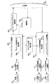
- the upper layer (L2 / L3) instructs random access preamble transmission.
- the physical layer (L1) transmits a random access preamble based on the instruction. If L1 is ACK, that is, a random access response is received from the base station apparatus. If L2 / L3 receives the instruction from L1, L2 / L3 instructs L1 to transmit the RRC connection request.
- the terminal device transmits an RRC connection request (PUSCH corresponding to UL-SCH to which an RRC message related to the RRC connection request is mapped) to the base station device (camping cell, EUTRAN, PLMN).
- the base station apparatus When the base station apparatus receives it, it transmits RRC connection setup (PDCCH and PDSCH related to DL-SCH to which an RRC message related to RRC connection setup is mapped) to the terminal apparatus.
- RRC connection setup (PDCCH and PDSCH related to DL-SCH to which an RRC message related to RRC connection setup is mapped)
- the terminal device When the terminal device receives the RRC connection setup at L2 / L3, the terminal device enters the connection mode.
- the terminal device L2 / L3 instructs L1 to transmit RRC connection setup completion, the procedure ends.
- L1 transmits RRC connection setup completion (PUSCH corresponding to UL-SCH to which an RRC message related to RRC connection setup completion is mapped) to the base station apparatus.
- the MTC terminal in the idle mode supports the MTC function until the initial access by the random access procedure is completed, the RRC connection is established, or the UL-SCH corresponding to the random access response grant is used.
- PDCCH may be monitored with the downlink transmission bandwidth indicated in MIB.
- the MTC terminal in the idle mode When the MTC terminal in the idle mode performs initial access according to the random access procedure, it may select a sequence indicating that it is an MTC terminal and transmit a random access preamble of the sequence.
- the base station apparatus receives the random access preamble, if the access of the MTC terminal is permitted, the base station apparatus may set the downlink resource allocation for the MTC terminal in the spare bit of the MIB.
- the MTC terminal detects the PDCCH corresponding to the random access response from the resource, completes the initial access, and establishes the initial RRC connection.
- the terminal device in the idle mode may receive a paging message using DRX (Discontinuous Reception) in order to reduce power consumption.
- DRX Discontinuous Reception
- PO Paging Occasion
- a PF Paging Frame
- the terminal device needs to monitor one PO every DRX cycle.
- PO and PF are determined using DRX parameters provided in the system information.
- the value of the DRX parameter is changed in the system information, the DRX parameter held in the terminal device is locally updated.
- IMSI International Mobile Subscriber Identity
- USIM Universal Subscriber Identity Module
- the idle mode MTC terminal performs PLMN reselection and cell reselection if information related to PDCCH configuration for the MTC terminal or information related to downlink resource allocation cannot be detected in the MIB.
- a terminal device indicating category 0 is one TTI, C-RNTI (Cell RNTI) / SPS (Semi-Persistent Scheduling) C-RNTI / P-RNTI / SI-RNTI / RA-RNTI (Random Access RNTI) 1000 bits can be received for the transport block associated with. Also, a terminal device indicating category 0 can receive up to 2216 bits for other transport blocks related to P-RNTI / SI-RNTI / RA-RNTI with one TTI.
- Requirement for UE category 0 is due to the assumption of UE category 0 and a single antenna receiver. Such a condition is referred to as UE category 0 applicability.
- Category 0 terminal monitors downlink quality based on CRS in order to detect downlink radio link quality of PCell.
- the category 0 terminal estimates the downlink radio link quality, and compares the two threshold values (Q out_Cat0 and Q in_Cat0 ) with the estimated value in order to monitor the downlink radio link quality of the PCell.
- the threshold value Qout_Cat0 is defined as a level corresponding to a 10% block error rate of PDCCH transmission assumed in consideration of a PCFICH error with a transmission parameter, in which a downlink radio link cannot be reliably received.
- the threshold Q in_Cat0 corresponds to a 2% block error rate of PDCCH transmission that can be received more reliably than the threshold Q out_Cat0 by taking into account PCFICH errors with transmission parameters.
- the out-of-sync PDCCH / PCFICH transmission parameters for UE category 0 are in DCI format 1A, and the number of OFDM symbols in PDCCH is determined based on the bandwidth.
- the bandwidth is 10 MHz or more, the number of OFDM symbols is 2 symbols.
- the bandwidth is 3 MHz or more and less than 10 MHz, the number of OFDM symbols is 3 symbols.
- the bandwidth is 1.4 MHz, the number of OFDM symbols is 4 symbols.
- the aggregation level of the PDCCH is 4 when the bandwidth is 1.4 MHz, and 8 when the bandwidth is 3 MHz or more.
- the ratio of the RE energy of PDCCH (EPRE: Energy Per Resource Element) and the average RE energy of RS is 4 dB regardless of the number of antenna ports of the PCell CRS.
- the ratio of the PCFICH RE energy and the average RE energy of RS is 4 dB when the number of CRS antenna ports is 1 antenna port, and 1 dB when the number of CRS antenna ports of PCell is 2 or 4 antenna ports. is there.
- the PDCCH / PCFICH transmission parameter for in-sync for UE category 0 is DCI format 1C, and the number of OFDM symbols of PDCCH is determined based on the bandwidth.
- the bandwidth is 10 MHz or more, the number of OFDM symbols is 2 symbols.
- the bandwidth is 3 MHz or more and less than 10 MHz, the number of OFDM symbols is 3 symbols.
- the bandwidth is 1.4 MHz, the number of OFDM symbols is 4 symbols.
- the aggregation level of PDCCH is 4.
- the ratio of the RE energy of PDCCH and the average RE energy of RS is 1 dB regardless of the number of CRS antenna ports.
- the ratio of the RE energy of PCFICH and the average RE energy of RS is 4 dB when the number of antenna ports of PCell CRS is 1 antenna port, and when the number of antenna ports of PCell CRS is 2 or 4 antenna ports, 1 dB.
- the terminal device and the base station device aggregate (aggregate) frequencies (component carriers or frequency bands) of a plurality of different frequency bands (frequency bands) by carrier aggregation so that they become one frequency (frequency band).
- the component carrier includes an uplink component carrier corresponding to the uplink (uplink cell) and a downlink component carrier corresponding to the downlink (downlink cell).
- frequency and frequency band may be used synonymously.
- a terminal device capable of carrier aggregation regards these as a frequency bandwidth of 100 MHz and performs transmission / reception.
- the component carriers to be aggregated may be continuous frequencies, or may be frequencies at which all or part of them are discontinuous.
- the usable frequency band is 800 MHz band, 2 GHz band, and 3.5 GHz band
- one component carrier is transmitted in the 800 MHz band
- another component carrier is transmitted in the 2 GHz band
- another component carrier is transmitted in the 3.5 GHz band. It may be.
- the frequency bandwidth of each component carrier may be a frequency bandwidth (for example, 5 MHz or 10 MHz) narrower than the receivable frequency bandwidth (for example, 20 MHz) of the terminal device, and the aggregated frequency bandwidth may be different from each other.
- the frequency bandwidth is preferably equal to one of the frequency bandwidths of the conventional cell in consideration of backward compatibility, but may be a frequency bandwidth different from that of the conventional cell.
- component carriers that are not backward compatible may be aggregated.
- the number of uplink component carriers assigned (set or added) to the terminal device by the base station device is preferably equal to or less than the number of downlink component carriers.
- a cell composed of an uplink component carrier in which an uplink control channel is set for requesting a radio resource and a downlink component carrier that is cell-specifically connected to the uplink component carrier is referred to as a PCell.
- the cell comprised from component carriers other than PCell is called SCell.
- the terminal device performs reception of a paging message, detection of update of broadcast information, initial access procedure, setting of security information, and the like in the PCell, while the SCell does not need to perform these.
- PCell is not subject to activation and deactivation control (that is, it is considered to be always activated), but SCell has a state of activation and deactivation, These state changes are explicitly specified by the base station apparatus, and the state is changed based on a timer set in the terminal apparatus for each component carrier.
- PCell and SCell are collectively referred to as a serving cell.
- carrier aggregation is communication by a plurality of cells using a plurality of component carriers (frequency bands), and is also referred to as cell aggregation.
- the terminal device may be wirelessly connected (RRC connection) to the base station device via a relay station device (or repeater) for each frequency. That is, the base station apparatus of this embodiment can be replaced with a relay station apparatus.
- the base station apparatus manages a cell, which is an area in which the terminal apparatus can communicate with the base station apparatus, for each frequency.
- One base station apparatus may manage a plurality of cells.
- the cells are classified into a plurality of types according to the size (cell size) of the area communicable with the terminal device. For example, the cell is classified into a macro cell and a small cell. Further, small cells are classified into femtocells, picocells, and nanocells according to the size of the area.
- the terminal device can communicate with a certain base station device
- the cell set to be used for communication with the terminal device among the cells of the base station device is a serving cell, and for other communication Cells that are not used are called peripheral cells.
- a plurality of configured serving cells include one PCell and one or a plurality of SCells.
- PCell is a serving cell in which an initial connection establishment procedure (RRC connection procedure procedure) has been performed, a serving cell that has started a connection re-establishment procedure (RRC connection reestablishment procedure), or a cell designated as PCell in a handover procedure.
- PCell operates at the primary frequency.
- the SCell may be set when the connection is (re-) established or afterwards.
- the SCell operates at a secondary frequency.
- the connection may be referred to as an RRC connection.
- a terminal device supporting CA may be aggregated by one PCell and one or more SCells.
- the terminal apparatus may code transport block codes for at least a predetermined number of transport blocks for each serving cell. In response to block decoding failure, the received soft channel bits corresponding to at least a predetermined range are retained.
- the MTC terminal may support only one radio access technology (RAT).
- RAT radio access technology
- the MTC terminal may support only one operating band. That is, the MTC terminal may not support a function related to carrier aggregation.
- the MTC terminal may support only TDD (Time Division Duplex) and HD-FDD (Half Duplex Frequency Division Division). In other words, the MTC terminal does not have to support FD-FDD (Full-Duplex-FDD).
- the MTC terminal may indicate which duplex mode / frame structure type is supported via higher layer signaling such as functional information.
- the MTC terminal may be a category 0 or category 1 LTE terminal. That is, the maximum number of bits of a transport block that can be transmitted / received by one MTI terminal in one TTI (Transmission Time Interval) may be limited. For example, the maximum number of bits per TTI may be limited to 1000 bits. In LTE, 1 TTI corresponds to 1 subframe.
- TTI and subframe are synonymous.
- the MTC terminal may support only one duplex mode / frame structure type.
- Frame structure type 1 can be applied to both FD-FDD and HD-FDD.
- FDD 10 subframes can be used for each of downlink transmission and uplink transmission at intervals of 10 ms.
- uplink transmission and downlink transmission are divided in the frequency domain.
- the terminal device In the HD-FDD operation, the terminal device cannot transmit and receive at the same time, but there is no restriction in the FD-FDD operation.
- the MTC terminal may support only a narrow bandwidth such as 1.4 MHz in the downlink and uplink. That is, the MTC terminal does not have to communicate with a wide bandwidth such as 20 MHz.
- the MTC terminal whose available bandwidth is limited may be operated with any system bandwidth. For example, scheduling for an MTC terminal that supports only a bandwidth of 1.4 MHz may be performed in an operating band having a system bandwidth of 20 MHz.
- the MTC terminal may support only one RF unit / baseband unit (eg, 1.4 MHz RF bandwidth) in the downlink and uplink.
- RF unit / baseband unit eg, 1.4 MHz RF bandwidth
- the base station apparatus may perform control / schedule so that FDM can be performed between a terminal that supports MTC (MTC terminal) and a terminal that does not support MTC (non-MTC terminal). That is, scheduling such as radio resource allocation for MTC terminals is performed in consideration of scheduling such as radio resource allocation for non-MTC terminals.
- Re-tuning time when frequency hopping or usage frequency is changed may be set by higher layer signaling.
- the transmission power for the MTC terminal may be reduced.
- the power class or the like may be set exclusively for the MTC terminal.
- the number of supported downlink transmission modes may be reduced. That is, when the base station apparatus indicates the number of downlink transmission modes as the function information from the MTC terminal or the downlink transmission mode supported by the MTC terminal, based on the function information, Sets the downlink transmission mode. Note that when a parameter for a downlink transmission mode that is not supported by the MTC terminal is set, the MTC terminal may ignore the setting. That is, the MTC terminal does not have to perform processing for the downlink transmission mode that is not supported.
- the downlink transmission mode is used to indicate a PDSCH transmission scheme corresponding to PDCCH / EPDCCH based on the set downlink transmission mode, RNTI type, DCI format, and search space.
- the terminal device can know whether PDSCH is transmitted at antenna port 0, transmitted at transmission diversity, or transmitted at a plurality of antenna ports.
- the terminal device can appropriately perform reception processing based on the information. Even if DCI related to PDSCH resource allocation is detected from the same type of DCI format, if the downlink transmission mode or RNTI type is different, the PDSCH is not always transmitted in the same transmission scheme.
- the processing load in the downlink and uplink may be reduced as compared with the conventional LTE terminal.
- the maximum transport block size for supported unicast and broadcast signaling may be reduced.
- the number of downlink signals that can be received simultaneously may be reduced.
- transmission and reception EVM (Error Vector Vector) requirements, including limited modulation schemes, may be relaxed.
- Physical control channel processing may be reduced (eg, reducing the number of blind decoding).
- physical data channel processing may be reduced (eg, downlink HARQ timeline relaxation, number of HARQ processes, etc.).
- the number of CQI / CSI reporting modes supported in the MTC terminal may be reduced. That is, when the base station apparatus indicates the number of CQI / CSI report modes or the CQI / CSI report mode supported by the MTC terminal as the function information from the MTC terminal, the base station apparatus is based on the function information. Then, the CQI / CSI report mode may be set. In addition, when a parameter for a CQI / CSI report mode that is not supported by the MTC terminal is set, the MTC terminal may ignore the setting. That is, the MTC terminal does not have to perform processing for the CQI / CSI report mode that is not supported.
- a technique for extending (improving) coverage may be applied in order to reduce power consumption. These techniques may be applied to both FDD and TDD.
- a subframe bundling technique with HARQ for a physical data channel may be included.
- control channel for example, PCFICH, PDCCH
- an iterative technique for a control channel may be included.
- the iterative technique refers to, for example, data mapped to physical channels / physical signals (UL-SCH data, DL-SCH data, user data, control data, etc.) every transmission (each transmission subframe, every TTI) It is to transmit without changing to. That is, it means that a physical channel / physical signal to which the same data is mapped is transmitted a predetermined number of times.
- bundling may change data to be mapped for each transmission.
- reception accuracy can be improved by performing reception signal addition processing as reception processing.
- a restriction or repetition technique may be included for PBCH, PHICH, and PUCCH.
- power boost by supporting a bandwidth (for example, 0.5 PRB) narrower than 1 PRB may be supported. That is, it may be supported that the power density is improved.
- resource allocation using EPDCCH with cross carrier scheduling and repetition may be included as a coverage extension technique.
- an operation without EPDCCH may be considered.
- a new physical channel format for SIB (System Information Block) / RAR (Random Access Response) / paging may be included.
- Information related to RAR and paging (PCH) is transmitted by being mapped to DL-SCH indicated by PDCCH (DCI format) with CRC scrambled by a certain RNTI, but parameters corresponding to coverage extension are added as DCI May be.
- the DCI field included in the DCI format may be different depending on the type of scrambled RNTI.
- DCI indicating the repetition time (number of repetitions) may be included. The value set in DCI indicating the repetition time (number of repetitions) may be determined based on information to be transmitted.
- a value set in DCI indicating the repetition time may be determined, or DCI indicating the repetition time (repetition count) is included in the DCI format. It does not have to be.
- SIB corresponding to channel bandwidth and coverage extension may be included as a coverage extension technique.
- an increase in the density of reference symbols and a frequency hopping technique may be supported.
- the probability of miss detection for PRACH and the initial acquisition time (initial synchronization time) between the terminal and the system for PSS / SSS / PBCH / SIB are considered even if the impact on power consumption to the terminal is considered. Good.
- a necessary coverage extension amount may be set for each cell, for each terminal, for each channel, or for each group of channels. Measurements and reports corresponding to the coverage extension may be defined.
- the coverage extension technology and the coverage extension function may be applied to each of the MTC terminal and the LTE terminal.
- a common solution may be applied to a low-complexity terminal and a coverage extension terminal.
- a power consumption reduction method for extending battery life may be applied to both standard coverage and extended coverage UE categories / types. For example, the actual transmission / reception time is reduced. Minimize the number of repetitive transmissions and receptions by minimizing control messages. Further, channel / signal change, improvement, redesign, addition / reduction may be performed. Also, measurement time, measurement report, feedback signaling, system information acquisition, synchronization acquisition time, etc. may be optimized to reduce power consumption.
- MTC technology and coverage extension technology may be optimized for HD-FDD and TDD.
- the processing related to mobility may be reduced.
- the MTC terminal may turn off the power.
- the MTC terminal may continue to receive and synthesize the PBCH until the MIB can be detected.
- the timing at which PUSCH transmission occurs PUCCH and PUSCH may be repeatedly transmitted a predetermined number of times at the timing when PUCCH transmission occurs. That is, PUCCH and PUSCH are transmitted simultaneously at the same timing (that is, the same subframe).
- the PUCCH may include a CSI report, HARQ-ACK, and SR.
- the terminal apparatus may be set in consideration of a predetermined power offset in order to adjust the transmission power of the PUCCH. If the PUSCH can be detected in the base station apparatus, the PUCCH can also be detected, so that it is not necessary to allocate much power to the PUCCH. However, when the PUCCH is repeatedly transmitted alone, the terminal device does not need to consider this predetermined power offset. When the PUCCH is repeatedly transmitted alone, it is preferable that the base station apparatus can detect it in a shorter interval.
- the number of repetitions of PUCCH is the number of repetitions of PUSCH in the case of simultaneous transmission of PUCCH and PUSCH.
- the number of repetitions of PUCCH is the number of repetitions set for PUCCH in the case of transmission using only PUCCH. It may be determined whether or not the predetermined offset is applied depending on whether or not simultaneous transmission with the PUSCH is performed. When the number of repetitions is set for the terminal device, repeated transmission of all physical channels is performed based on the number.
- the terminal apparatus supports the simultaneous transmission of PUCCH and PUSCH, and the same number of repetitions in the same subframe.
- PUCCH and PUSCH are transmitted simultaneously in a repeated period.
- the transmission power of PUCCH may be set using a power offset if it is set by higher layer signaling. Further, when the transmission of PUCCH does not overlap with the transmission of PUSCH, the terminal apparatus sets the transmission power of PUCCH without using the power offset.
- the base station apparatus may set the power offset of PUCCH using higher layer signaling.
- the transmission power of PUCCH may be set based on a power control adjustment value using a transmission power control command for PUSCH. That is, it is not necessary to consider the power control adjustment value using the transmission power control command for PUCCH.
- power control adjustment values used for setting each transmission power may be set individually. Good. That is, when the base station apparatus is instructed to use the same power control adjustment value using higher layer signaling, the transmission power of PUSCH and PUCCH is set using the same power control adjustment value.
- transmission power is set using each power control adjustment value. Further, when the SRS is repeatedly transmitted in the same subframe, the transmission power may be set using the same power control adjustment value.
- the MIB in which the parameter (information) for the MTC terminal is set in the spare bit and the MIB in which the parameter (information) for the MTC terminal is not set are not necessarily handled as the same MIB.
- MIB type A an MIB in which a parameter (information) for an MTC terminal is not set in a spare bit
- MIB type B in which a parameter (information) for an MTC terminal is set in a spare bit
- the MIB type A has an interval of 40 ms.
- MIB type B may be transmitted at intervals of 20 ms.
- the PBCH subframe and the PBCH radio frame in which the MIB type A and the MIB type B are arranged may be different subframes and radio frames.
- the LTE terminal receives only MIB type A, but the MTC terminal may receive MIB type A and MIB type B.
- the MIB in which the parameter (information) for the MTC terminal is set in the spare bit may be transmitted not only in the above-described PBCH cycle but also in another cycle. That is, an MIB in which parameters (information) for MTC terminals are set in spare bits may be transmitted in two subframe sets. That is, the LTE terminal can receive the MIB of the first subframe set. The MTC terminal can receive the MIB of the first subframe set and the second subframe set.
- SIB SIB1, SI message, new SIB
- SIB SIB1, SI message, new SIB
- the SIB in which parameters (information) for the MTC terminal are set may be transmitted in two subframe sets. That is, the LTE terminal can receive the SIB of the first subframe set.
- the MTC terminal can receive the SIBs of the first subframe set and the second subframe set.
- the PDCCH and / or EPDCCH setting corresponding to the SIB corresponds to the MTC terminal. That is, the MTC terminal does not expect such SIB (DL-SCH corresponding to SIB) to be transmitted on the PDCCH / EPDCCH of the downlink bandwidth that is not supported by the MTC terminal.
- the PCH including the change notification of the SIB (SIB1, SI message, new SIB) in which parameters (information) for the MTC terminal are set may be transmitted not only in the above-described period but also in another period. That is, the PCH including the SIB change notification in which parameters (information) for the MTC terminal are set may be transmitted in two subframe sets. That is, the LTE terminal can receive the PCH of the first subframe set. The MTC terminal can receive the PCH of the first subframe set and the second subframe set. At that time, the setting of PDCCH and / or EPDCCH corresponding to this PCH corresponds to the MTC terminal. That is, the MTC terminal does not expect such PCH to be transmitted on the PDCCH / EPDCCH of the downlink bandwidth that is not supported by the MTC terminal.
- the transmission bandwidth supported by the MTC terminal is narrow (for example, 5 MHz or less)
- only the local arrangement may be supported as the EPDCCH transmission type. That is, when the transmission bandwidth supported by the MTC terminal is narrow (for example, 5 MHz or less), the EPDCCH transmission type may not be distributed.
- the terminal device that supports the MTC function monitors the PBCH and PDCCH from the cell. Also good.
- the PDCCH of the MIB and / or SI message PDCCH is monitored based on resource allocation, subframe number, OFDM symbol (start symbol), and the like included in the setting.
- the MTC terminal may repeatedly receive the PDCCH to improve the reception accuracy.
- the MTC terminal acquires paging information from the PCH indicated by the DCI included in the PDCCH.
- the P-RNTI is set using system information or higher layer signaling.
- the MTC terminal acquires paging information from the PCH indicated by the DCI included in the PDCCH.
- the information regarding the setting of this EPDCCH is set using higher layer signaling.
- the PDCCH region assigned to the downlink transmission bandwidth is used. If a PDCCH with a CRC scrambled by the P-RNTI is received, the MTC terminal acquires paging information from the PCH indicated by the DCI included in the PDCCH.
- the P-RNTI is a default value or a predetermined value. That is, the value of this P-RNTI may not be set using higher layer signaling.
- the MTC terminal assigns to the downlink transmission bandwidth. PDCCH is not monitored from the assigned PDCCH region. Since the MTC terminal cannot monitor the PDCCH with the CRC scrambled by the P-RNTI with an unsupported bandwidth, it cannot detect the PCH.
- the base station apparatus may not change the system information related to the MTC terminal to the paging information.
- PCell In PCell, all signals can be transmitted / received, but in SCell, there are signals that cannot be transmitted / received.
- PUCCH is transmitted only by PCell.
- PRACH is transmitted only by PCell unless a plurality of TAGs (TimingTiAdvance Group) are set between cells.
- PBCH is transmitted only by PCell.
- MIB Master Information Block
- the base station device may instruct the terminal device to transmit PUCCH or MIB by SCell. Good. That is, when the terminal device supports the function, the base station device may set a parameter for transmitting PUCCH or MIB by SCell to the terminal device.
- PCell RLF (Radio Link Failure) is detected.
- the SCell does not recognize that RLF has been detected even if the conditions for detecting RLF are met.
- the lower layer of the PCell notifies the upper layer of the PCell that the RLF condition is satisfied.
- SPS Semi-Persistent Scheduling
- DRX Discontinuous Transmission
- SCell you may perform DRX same as PCell.
- information / parameters related to MAC settings are basically shared with PCells in the same cell group. Some parameters (for example, sTAG-Id) may be set for each SCell. Some timers and counters may be applied only to the PCell. Only applicable timers and counters may be set for the SCell.
- FIG. 3 is a schematic diagram illustrating an example of a block configuration of the base station apparatus 2 according to the present embodiment.
- the base station apparatus 2 includes an upper layer (upper layer control information notification unit) 501, a control unit (base station control unit) 502, a codeword generation unit 503, a downlink subframe generation unit 504, and an OFDM signal transmission unit (downlink transmission).
- the downlink subframe generation unit 504 includes a downlink reference signal generation unit 505.
- the uplink subframe processing unit 510 includes an uplink control information extraction unit (CSI acquisition unit / HARQ-ACK acquisition unit / SR acquisition unit) 511.
- FIG. 4 is a schematic diagram illustrating an example of a block configuration of the terminal device 1 according to the present embodiment.
- the terminal device 1 includes a reception antenna (terminal reception antenna) 601, an OFDM signal reception unit (downlink reception unit) 602, a downlink subframe processing unit 603, a transport block extraction unit (data extraction unit) 605, a control unit (terminal) Control unit) 606, upper layer (upper layer control information acquisition unit) 607, channel state measurement unit (CSI generation unit) 608, uplink subframe generation unit 609, SC-FDMA signal transmission unit (UCI transmission unit) 611 and 612 And transmission antennas (terminal transmission antennas) 613 and 614.
- the downlink subframe processing unit 603 includes a downlink reference signal extraction unit 604.
- the uplink subframe generation unit 609 includes an uplink control information generation unit (UCI generation unit) 610.
- UCI generation unit uplink control information generation unit
- the control unit 502 includes MCS (Modulation & Coding Scheme) indicating the modulation scheme and coding rate in the downlink, downlink resource allocation indicating RB used for data transmission, and information used for HARQ control ( Redundancy version, HARQ process number, and new data index) are stored, and the codeword generation unit 503 and the downlink subframe generation unit 504 are controlled based on these.
- Downlink data also referred to as a downlink transport block, DL-SCH data, or DL-SCH transport block
- sent from the higher layer 501 is controlled by the control unit 502 in the codeword generation unit 503.
- the downlink subframe generation unit 504 generates a downlink subframe according to an instruction from the control unit 502.
- the codeword generated in the codeword generation unit 503 is converted into a modulation symbol sequence by a modulation process such as PSK (Phase Shift Keying) modulation or QAM (Quadrature Amplitude Modulation) modulation.
- the modulation symbol sequence is mapped to REs in some RBs, and a downlink subframe for each antenna port is generated by precoding processing.
- the transmission data sequence transmitted from the upper layer 501 includes upper layer control information which is control information (for example, dedicated (individual) RRC (Radio Resource Control) signaling) in the upper layer.
- the downlink reference signal generation section 505 generates a downlink reference signal.
- the downlink subframe generation unit 504 maps the downlink reference signal to the RE in the downlink subframe according to an instruction from the control unit 502.
- the downlink subframe generated by the downlink subframe generation unit 504 is modulated into an OFDM signal by the OFDM signal transmission unit 506 and transmitted via the transmission antenna 507.
- the downlink subframe generation unit 504 can also have a capability of generating a physical layer downlink control channel such as PDCCH or EPDCCH and mapping it to the RE in the downlink subframe.
- a physical layer downlink control channel such as PDCCH or EPDCCH
- the OFDM signal is received by the OFDM signal receiving unit 602 via the receiving antenna 601 and subjected to OFDM demodulation processing.
- the downlink subframe processing unit 603 first detects a physical layer downlink control channel such as PDCCH or EPDCCH. More specifically, the downlink subframe processing unit 603 decodes the PDCCH or EPDCCH as transmitted in an area where the PDCCH or EPDCCH can be allocated, and confirms a CRC (Cyclic Redundancy Check) bit added in advance. (Blind decoding) That is, the downlink subframe processing unit 603 monitors PDCCH and EPDCCH. One CRC bit is assigned to one terminal such as an ID (C-RNTI (Cell-Radio Network Temporary Identifier), SPS-C-RNTI (Semi-Persistent Scheduling-C-RNTI)) assigned in advance by the base station apparatus.
- C-RNTI Cell-Radio Network Temporary Identifier
- SPS-C-RNTI Semi-Persistent Scheduling-C-RNTI
- the downlink subframe processing unit 603 recognizes that the PDCCH or EPDCCH has been detected, and uses the control information included in the detected PDCCH or EPDCCH, if it matches the terminal unique identifier or Temporary C-RNTI) Take out PDSCH.
- the control unit 606 holds MCS indicating the modulation scheme and coding rate in the downlink based on the control information, downlink resource allocation indicating the RB used for downlink data transmission, and information used for HARQ control, based on these And controls the downlink subframe processing unit 603, the transport block extraction unit 605, and the like. More specifically, the control unit 606 performs control so as to perform RE demapping processing and demodulation processing corresponding to the RE mapping processing and modulation processing in the downlink subframe generation unit 504.
- the PDSCH extracted from the received downlink subframe is sent to the transport block extraction unit 605.
- the downlink reference signal extraction unit 604 in the downlink subframe processing unit 603 extracts a downlink reference signal from the downlink subframe.
- the transport block extraction unit 605 performs rate matching processing in the codeword generation unit 503, rate matching processing corresponding to error correction coding, error correction decoding, and the like, extracts transport blocks, and sends them to the upper layer 607. It is done.
- the transport block includes upper layer control information, and the upper layer 607 informs the control unit 606 of necessary physical layer parameters based on the upper layer control information.
- the plurality of base station apparatuses 2 transmit individual downlink subframes, and the terminal apparatus 1 receives these, so that the above processing is performed on the downlink subframes for each of the plurality of base station apparatuses 2. On the other hand, each may be performed.
- the terminal device 1 may or may not recognize that a plurality of downlink subframes are transmitted from the plurality of base station devices 2. When not recognizing, the terminal device 1 may simply recognize that a plurality of downlink subframes are transmitted in a plurality of cells. Further, the transport block extraction unit 605 determines whether or not the transport block has been correctly detected, and the determination result is sent to the control unit 606.
- the transport block extraction unit 605 may include a buffer unit (soft buffer unit).
- the buffer unit In the buffer unit, the extracted transport block information can be temporarily stored. For example, when the transport block extraction unit 605 receives the same transport block (retransmitted transport block), if the decoding of the data for this transport block is not successful, the transport block extraction unit 605 temporarily stores it in the buffer unit. The stored data for the transport block and the newly received data are combined (synthesized), and an attempt is made to decode the combined data. The buffer unit flushes the data when the temporarily stored data is no longer needed or when a predetermined condition is satisfied. The condition of data to be flushed differs depending on the type of transport block corresponding to the data.
- a buffer unit may be prepared for each type of data. For example, a message 3 buffer or a HARQ buffer may be prepared as the buffer unit, or may be prepared for each layer such as L1 / L2 / L3. Note that flushing information / data includes flushing a buffer storing information and data.
- the buffer section of the MTC terminal temporarily buffers the information.
- SIB SIB1 and other SI messages
- overflow may occur in the buffer section.
- the SIB does not include information related to the PDCCH setting for the MTC terminal
- the MIB system information is held and the SIB system information is flushed.
- the SIB contains information related to the PDCCH setting for the MTC terminal
- overflow occurs due to receiving the MIB and SIB
- the SIB system information is retained and the MIB system information is flushed. To do.
- the paging information in the PCH does not include the information on the PDCCH setting, the MIB or SIB and the paging information Even if an overflow occurs due to reception of information, the information regarding the PDCCH setting for the MTC terminal included in the MIB or SIB is preferentially held, and the overflowed paging information is flushed. However, if the received paging information includes an SIB change notification including information related to the PDCCH setting for the MTC terminal, the paging information is retained when an overflow occurs due to reception of the MIB and the paging information. And flush the MIB.
- the buffer unit of the MTC terminal determines the priority order for holding the buffer based on information related to the PDCCH setting for the MTC terminal.
- the buffer unit of the MTC terminal may determine the information to be flushed depending on whether or not the parameter related to the setting of the MTC terminal is included.
- the buffer unit of the MTC terminal in the idle mode may preferentially hold information related to the setting of the MTC terminal and may flush other information. For example, if the information related to the setting of the MTC terminal is set only for the MIB, the buffer unit may hold the MIB and flush other information that has overflowed. Further, if information related to the setting of the MTC terminal is set only for the SIB, the buffer unit may hold the SIB and flush other information that has overflowed.
- the buffer unit of the MTC terminal in the connection mode relates to the setting of the MTC terminal set in the RRC message if information on the setting of the MTC terminal is set in each of the MIB, SIB, and RRC messages. Information may be retained and other information that has overflowed may be flushed. When information related to the setting of the MTC terminal is set only in a specific message, the message may be preferentially held and other information that has overflowed may be flushed.
- the MTC terminal preferentially holds information related to the PDCCH setting.
- the downlink reference signal extracted by the downlink reference signal extraction unit 604 is sent to the channel state measurement unit 608 under the instruction of the control unit 606, and the channel state measurement unit 608 performs channel state and / or interference. And CSI is calculated based on the measured channel conditions and / or interference.
- the control unit 606 sends the HARQ-ACK (DTX (untransmitted), ACK (successful detection), or NACK ( Detection failure)) and mapping to downlink subframes.
- the terminal device 1 performs these processes on the downlink subframes for each of a plurality of cells.
- Uplink control information generating section 610 generates PUCCH including the calculated CSI and / or HARQ-ACK.
- the PUSCH including the uplink data sent from the higher layer 607 and the PUCCH generated in the uplink control information generation unit 610 are mapped to the RB in the uplink subframe, and the uplink A subframe is generated.
- the SC-FDMA signal is received by the SC-FDMA signal receiving unit 509 via the receiving antenna 508, and SC-FDMA demodulation processing is performed.
- Uplink subframe processing section 510 extracts an RB to which PUCCH is mapped in accordance with an instruction from control section 502, and uplink control information extraction section 511 extracts CSI included in PUCCH.
- the extracted CSI is sent to the control unit 502.
- CSI is used for control of downlink transmission parameters (MCS, downlink resource allocation, HARQ, etc.) by the control unit 502.
- the base station apparatus From the power headroom report, the base station apparatus assumes the maximum output power P CMAX set by the terminal apparatus, and assumes an upper limit value of power for each physical uplink channel based on the physical uplink channel received from the terminal apparatus. To do. Based on these assumptions, the base station apparatus determines the value of the transmission power control command for the physical uplink channel, and transmits it to the terminal apparatus using the PDCCH with the downlink control information format. By doing so, the power adjustment of the transmission power of the physical uplink channel transmitted from the terminal apparatus is performed.
- the power value required for each PUSCH transmission is a parameter set by an upper layer, an adjustment value determined by the number of PRBs assigned to the PUSCH transmission by resource assignment, a downlink path loss, and a multiplication thereof. In the above description, it is calculated based on a coefficient to be calculated, an adjustment value determined by a parameter indicating an offset of MCS applied to UCI, a value based on a TPC command, and the like.
- the power value required for each PUCCH transmission is used for parameters set by higher layers, downlink path loss, adjustment values determined by UCI transmitted on the PUCCH, adjustment values determined by PUCCH format, and transmission of the PUCCH.
- the present invention is not limited to this.
- An upper limit is set for the required power value, and the minimum value between the value based on the above parameter and the upper limit value (for example, P CMAX, c which is the maximum output power value in the serving cell c ) is set to the required power. It can also be used as a value.
- a program that operates in the base station device 2 and the terminal device 1 related to the present invention is a program that controls a CPU (Central Processing Unit) or the like (a computer functions) so as to realize the functions of the above-described embodiments related to the present invention.
- Program Information handled by these devices is temporarily stored in RAM (Random Access Memory) during the processing, and then stored in various ROMs such as Flash ROM (Read Only Memory) and HDD (Hard Disk Drive). Reading, correction, and writing are performed by the CPU as necessary.
- RAM Random Access Memory
- ROMs Read Only Memory
- HDD Hard Disk Drive
- the program for realizing the control function may be recorded on a computer-readable recording medium, and the program recorded on the recording medium may be read by the computer system and executed.
- the “computer system” is a computer system built in the terminal device 1 or the base station device 2 and includes hardware such as an OS and peripheral devices.
- the “computer-readable recording medium” refers to a storage device such as a flexible medium, a magneto-optical disk, a portable medium such as a ROM or a CD-ROM, and a hard disk incorporated in a computer system.
- the “computer-readable recording medium” is a medium that dynamically holds a program for a short time, such as a communication line when a program is transmitted via a network such as the Internet or a communication line such as a telephone line.
- a volatile memory inside a computer system serving as a server or a client may be included, which holds a program for a certain period of time.
- the program may be a program for realizing a part of the functions described above, and may be a program capable of realizing the functions described above in combination with a program already recorded in a computer system.
- the base station device 2 in the above-described embodiment can be realized as an aggregate (device group) composed of a plurality of devices.
- Each of the devices constituting the device group may include a part or all of each function or each functional block of the base station device 2 according to the above-described embodiment. It is only necessary to have each function or each functional block of the base station device 2 as a device group.
- the terminal device 1 according to the above-described embodiment can also communicate with the base station device as an aggregate.
- the base station apparatus 2 in the above-described embodiment may be EUTRAN (Evolved Universal Terrestrial Radio Access Network). Moreover, the base station apparatus 2 in the above-described embodiment may have a part or all of the functions of the upper node for the eNodeB.
- EUTRAN Evolved Universal Terrestrial Radio Access Network
- part or all of the terminal device 1 and the base station device 2 in the above-described embodiment may be realized as an LSI that is typically an integrated circuit, or may be realized as a chip set. Each functional block of the terminal device 1 and the base station device 2 may be individually chipped, or part or all of them may be integrated into a chip. Further, the method of circuit integration is not limited to LSI, and may be realized by a dedicated circuit or a general-purpose processor. In addition, when an integrated circuit technology that replaces LSI appears due to progress in semiconductor technology, an integrated circuit based on the technology can also be used.
- a cellular mobile station device (a mobile phone or a mobile terminal) is described as an example of a terminal device or a communication device.
- the present invention is not limited to this and is installed indoors and outdoors. It can also be applied to terminal devices or communication devices such as stationary or non-movable electronic devices such as AV equipment, kitchen equipment, cleaning / washing equipment, air conditioning equipment, office equipment, vending machines, and other life equipment.
- the present invention has the following features.
- a terminal apparatus is a terminal apparatus that communicates with a base station apparatus, and transmits a function information indicating that the first function and the second function are supported;
- a receiving unit that receives a first parameter corresponding to the first function and a second parameter corresponding to the second function via higher layer signaling, wherein the transmitting unit includes the first parameter If the above parameter and the second parameter are set, PUSCH (Physical Uplink Shared Channel) and PUCCH (Physical Uplink Control Channel) are repeatedly transmitted using the same number of subframes.
- PUSCH Physical Uplink Shared Channel
- PUCCH Physical Uplink Control Channel
- a terminal apparatus is the terminal apparatus described above, and when the PUSCH and the PUCCH are transmitted in the same subframe, the transmission unit sets transmission power for the PUCCH. At this time, it is set using a predetermined power offset.
- a terminal apparatus is the terminal apparatus described above, and when the PUCCH is not transmitted in the same subframe as the PUSCH, the transmission unit sets transmission power for the PUCCH. Set without using a predetermined power offset.
- a base station apparatus is a base station apparatus that communicates with a terminal apparatus, and receives function information indicating that the terminal apparatus supports the first function and the second function.
- a receiving unit that receives and a cell that permits access to a terminal device that supports the function information
- a first parameter corresponding to the first function and a second parameter corresponding to the second function A transmission unit that transmits parameters using higher layer signaling, and when the transmission unit has a cell that allows access to a terminal device that supports the function information
- PUCCH Physical-Uplink-Control-Channel
- a predetermined power offset for is transmitted using higher layer signaling.
- a method is a method in a terminal apparatus that communicates with a base station apparatus, the step of transmitting function information indicating that the first function and the second function are supported; Receiving a first parameter corresponding to a first function and a second parameter corresponding to the second function via higher layer signaling; and the first parameter and the second parameter are: If it is set, there is a step of repeatedly transmitting PUSCH (Physical Uplink Shared Channel) and PUCCH (Physical Uplink Control Channel) using the same number of times and the same subframe.
- PUSCH Physical Uplink Shared Channel
- PUCCH Physical Uplink Control Channel
- the method according to an aspect of the present invention is the method described above, wherein when the PUSCH and the PUCCH are transmitted in the same subframe, a predetermined power offset is set when setting transmission power for the PUCCH. And, when the PUCCH is not transmitted in the same subframe as the PUSCH, when setting the transmission power for the PUCCH, setting without using a predetermined power offset.
- a method according to an aspect of the present invention is a method in a base station device that communicates with a terminal device, and the function information indicating that the terminal device supports the first function and the second function.
- a first parameter corresponding to the first function and a second parameter corresponding to the second function when receiving a cell that allows access to a terminal device that supports the function information; Is transmitted using higher layer signaling, and a predetermined power offset for PUCCH (Physical Uplink Control ⁇ Channel) And transmitting using.
- PUCCH Physical Uplink Control ⁇ Channel
- a terminal apparatus is a terminal apparatus that communicates with a base station apparatus, a receiving unit that receives a master information block (MIB) and one or more system information blocks (SIB); A transmission unit that transmits function information indicating that the terminal device having the first function is used, and a cell permitted to be accessed by the terminal device having the first function is indicated using the MIB or the SIB.
- MIB or the SI message includes information related to PDCCH (Physical Downlink Control Channel) setting
- the receiving unit determines whether the reception unit performs resource allocation based on the information related to the PDCCH setting. Receive PDCCH.
- a terminal device is the above-described terminal device, wherein the reception unit receives a CRC (Cyclic Redundancy Check) scrambled from the PDCCH by a first RNTI (Radio Network Temporary Identifier).
- the accompanying DCI (Downlink Control Information) format is detected, and PCH (Paging Channel) is detected based on the resource allocation detected from the DCI format.
- a terminal device is the terminal device described above, wherein the receiving unit receives the first RNTI using higher layer signaling.
- a terminal device is the terminal device described above, wherein the reception unit includes a case where the MIB or the SIB does not include information regarding the setting of the PDCCH, and an EPDCCH (Enhanced If the second RNTI for PCH is set in the information regarding the setting of (PDCCH), a DCI format with a CRC scrambled by the second RNTI is detected from the EPDCCH, and the PCH is detected based on the DCI format. Is detected.
- a terminal device is the above-described terminal device, wherein the reception unit does not include information regarding the setting of the PDCCH in the MIB or the SIB, and the setting of the EPDCCH If the second RNTI for the PCH is not set in the information on the information and the first function information corresponds to the downlink transmission bandwidth included in the MIB or the SIB, the downlink A DCI format with a CRC scrambled by a third RNTI which is a predetermined value is detected from the PDCCH allocated to the link transmission bandwidth, and a PCH is detected based on the DCI format.
- a terminal apparatus is the terminal apparatus described above, wherein resource allocation based on the setting of the PDCCH is a resource block index corresponding to a downlink transmission bandwidth indicated by the MIB or the SIB. It is represented by
- a base station apparatus is a base station apparatus that communicates with a terminal apparatus, and when the terminal apparatus indicates that the first function is supported, the first station apparatus A transmission unit that transmits information indicating whether or not there is a cell that permits access to a terminal device that supports the function using higher layer signaling including system information, and the transmission unit supports the first function If there is a cell that permits access to the terminal device, information related to setting of PDCCH (Physical Downlink Control Channel) for the terminal device that supports the first function is set in the master information block or the system information block.
- PDCCH Physical Downlink Control Channel
- a base station apparatus is the base station apparatus described above, wherein the transmission unit is accompanied by a CRC (Cyclic Redundancy Check) scrambled by a first RNTI (Radio Network Temporary Identifier).
- a DCI (Downlink Control Information) format is transmitted based on the setting of the PDCCH, and the first RNTI is an RNTI of a PCH (PagingIChannel) for a terminal device that supports the first function.
- a method is a method in a terminal device that communicates with a base station device, the step of receiving a master information block (MIB), and receiving one or more system information blocks (SIB). And a step of transmitting function information indicating having the first function, and a cell that is permitted to be accessed by the terminal device of the first function using the MIB or the SIB. If the MIB or the SI message includes information related to PDCCH (Physical Downlink Control Channel) setting, the PDCCH is received from the cell based on resource allocation based on the information related to the PDCCH setting. Steps.
- MIB master information block
- SIB system information blocks
- a method according to an aspect of the present invention is a method in a base station apparatus that communicates with a terminal device, and when the terminal device indicates that the first function is supported, A step of transmitting information indicating whether or not there is a cell allowing access to a terminal device supporting the function using higher layer signaling including system information; and permitting access to the terminal device supporting the first function If there is a cell to perform, there is a step of setting information relating to setting of PDCCH (Physical Downlink Control Control Channel) for the terminal device supporting the first function in the master information block or the system information block.
- PDCCH Physical Downlink Control Control Channel
- a terminal apparatus is a terminal apparatus that communicates with a base station apparatus, and a transmission unit that transmits functional information indicating that the first function is supported to the base station apparatus; And a receiving unit that detects an MIB (Master Information Block) from a PBCH (Physical Broadcast Channel), and the receiving unit is permitted to access a terminal device that supports the first function from the base station device. Then, the first information related to the downlink resource allocation for the terminal device supporting at least the first function is detected from the MIB.
- MIB Master Information Block
- a terminal device is the above-described terminal device, wherein the receiving unit is configured to perform PDCCH for a terminal device that supports at least the first function based on the first information. (Physical Downlink Control Channel) is received.
- PDCCH Physical Downlink Control Channel
- a terminal device is the above-described terminal device, wherein the reception unit has a CRC (Cyclic Redundancy check) of SI-RNTI (System Information-Radio Network Temporary Identifier) in the PDCCH. If it is scrambled, the system information for the terminal device supporting the first function is detected from PDSCH (Physical Downlink Shared Channel) corresponding to the PDCCH.
- CRC Cyclic Redundancy check
- SI-RNTI System Information-Radio Network Temporary Identifier
- a terminal device is the terminal device described above, and the value of the SI-RNTI is a default value.
- a terminal device is the above terminal device, wherein the receiving unit sets a physical channel / physical signal for the terminal device supporting the first function from the system information. Detect information about.
- a base station apparatus is a base station apparatus that communicates with a terminal apparatus, and is a downlink resource for a terminal apparatus that supports at least a first function in an MIB (Master Information Block).
- a transmission unit that sets and transmits first information related to allocation is provided, and the transmission unit transmits a PDCCH (Physical-Downlink-Control-Channel) corresponding to the downlink resource allocation.
- PDCCH Physical-Downlink-Control-Channel
- a method according to an aspect of the present invention is a method in a terminal apparatus that communicates with a base station apparatus, and transmits function information indicating that the first function is supported to the base station apparatus; , If detecting MIB (Master Information Block) from PBCH (Physical Broadcast Channel) and access from the base station device to the terminal device supporting the first function is permitted from the MIB, Detecting at least first information related to downlink resource allocation for a terminal device supporting at least the first function.
- MIB Master Information Block
- a method according to an aspect of the present invention is a method in a base station apparatus that communicates with a terminal apparatus, and a downlink resource for a terminal apparatus that supports at least a first function in an MIB (Master Information Block).
- MIB Master Information Block
- a terminal apparatus is a terminal apparatus that communicates with a base station apparatus, and supports a first function, and a terminal having a first function in a master information block (MIB)
- MIB master information block
- the buffer unit temporarily buffers information related to the PDCCH settings, and the buffer unit receives a system information block (SIB).
- SIB system information block
- a terminal device is the terminal device described above, wherein if the buffer unit overflows when receiving paging information, priority is given to information related to the setting of the PDCCH. And flush the overflowed paging information.
- a terminal device is the terminal device described above, wherein the buffer unit includes the MIB and the SIB when the SIB includes information on the setting of the PDCCH. If overflow occurs due to reception, the MIB is flushed.
- a terminal device is the terminal device described above, wherein the buffer unit receives paging information for notifying the change of the SIB, and receives the MIB and the paging information. If this causes an overflow, the MIB is flushed.
- a method according to an aspect of the present invention is a method in a terminal apparatus that communicates with a base station apparatus, and supports the first function, and the master information block (MIB) has the first function.
- a step of temporarily buffering information relating to the setting of the PDCCH when information related to setting of PDCCH (Physical Downlink Control Channel) for the terminal device is included, and receiving a system information block (SIB) Therefore, if an overflow occurs, there is a step of preferentially holding information related to the setting of the PDCCH and a step of flushing the overflowed SIB.
- SIB system information block
- a method according to an aspect of the present invention is the method described above, wherein if overflow occurs due to reception of paging information, the step of preferentially holding information regarding the setting of the PDCCH; Flushing the overflowed paging information.
- the method according to one aspect of the present invention is the method described above, and when the SIB includes information related to the setting of the PDCCH, overflow occurs by receiving the MIB and the SIB. If so, the method includes a step of flushing the MIB.
- the method according to one aspect of the present invention is the method described above, wherein the paging information for notifying the change of the SIB is received, and the overflow occurs due to the reception of the MIB and the paging information. Comprises flushing the MIB.
Landscapes
- Engineering & Computer Science (AREA)
- Computer Networks & Wireless Communication (AREA)
- Signal Processing (AREA)
- Computer Security & Cryptography (AREA)
- Mobile Radio Communication Systems (AREA)
- Telephonic Communication Services (AREA)
Abstract
In order to perform efficient communications, a terminal device is provided that communicates with a base station device and comprises a buffer unit that temporarily buffers information relating to PDCCH settings, if a first function is supported and information relating to said PDCCH settings is included in an MIB, said PDCCH settings being for the terminal device having the first function. If the buffer unit generates an overflow as a result of receiving an SIB, the buffer unit prioritises holding information relating to PDCCH settings and flushes the overflow SIB.
Description
本発明の実施形態は、効率的なチャネル状態情報の共有を実現する端末装置、基地局装置および方法の技術に関する。
Embodiments of the present invention relate to a technology of a terminal device, a base station device, and a method for realizing efficient sharing of channel state information.
標準化プロジェクトである3GPP(3rd General Partnership Project)において、OFDM(Orthogonal Frequency Division Multiplexing)通信方式やリソースブロックと呼ばれる所定の周波数・時間単位の柔軟なスケジューリングの採用によって、高速な通信を実現させたEUTRA(Evolved Universal Terrestrial Radio Access)の標準化が行なわれた。EUTRAにおける標準化技術を採用した通信全般をLTE(Long Term Evolution)通信と称する場合もある。
In the standardization project 3GPP (3rd General Partnership Project), EUTRA (High-speed communication is realized by adopting OFDM (Orthogonal Frequency Frequency Division) Multiplexing (OFDM) communication method and flexible scheduling of predetermined frequency and time units called resource blocks. Evolved (Universal Terrestrial Radio Access) has been standardized. In general, communication using EUTRA standardized technology is sometimes referred to as LTE (Long Term Evolution) communication.
また、3GPPでは、より高速なデータ伝送を実現し、EUTRAに対して上位互換性を持つA-EUTRA(Advanced EUTRA)の検討を行なっている。EUTRAでは、基地局装置がほぼ同一のセル構成(セルサイズ)から成るネットワークを前提とした通信システムであったが、A-EUTRAでは、異なる構成の基地局装置(セル)が同じエリアに混在しているネットワーク(異種無線ネットワーク、ヘテロジニアスネットワーク)を前提とした通信システムの検討が行なわれている。
Also, 3GPP is studying A-EUTRA (Advanced) EUTRA), which realizes higher-speed data transmission and has upward compatibility with EUTRA. In EUTRA, a communication system is premised on a network in which base station apparatuses have substantially the same cell configuration (cell size). However, in A-EUTRA, base station apparatuses (cells) having different configurations are mixed in the same area. Communication systems based on existing networks (heterogeneous wireless networks, heterogeneous networks) are being studied.
3GPPでは、スマートメーターなどの携帯電話以外の低移動性または固定の通信装置(端末装置および/または基地局装置)を用いて行なわれるマシン型通信(MTC)について検討されている(非特許文献1)。
In 3GPP, machine type communication (MTC) performed using a low mobility or fixed communication device (terminal device and / or base station device) other than a mobile phone such as a smart meter is examined (Non-Patent Document 1). ).
非特許文献1において、マシン型通信の低コスト化を行なう際に、従来では実現できていた機能が実現できない、または、実現が困難となる可能性がある。
In Non-Patent Document 1, when reducing the cost of machine-type communication, there is a possibility that functions that could be realized in the past cannot be realized or are difficult to realize.
マシン型通信を行なう際に、従来の通信装置(端末装置および/または基地局装置)が実現可能な機能を備えていない可能性があるため、従来の送信電力制御方法および送信制御方法をそのまま用いることができない。
When performing machine type communication, there is a possibility that a conventional communication device (terminal device and / or base station device) may not have a function that can be realized, so the conventional transmission power control method and transmission control method are used as they are. I can't.
本発明は上記の点に鑑みてなされたものであり、その目的は、マシン型通信であっても効率的に通信を制御することができる端末装置、基地局装置および方法を提供することである。
The present invention has been made in view of the above points, and an object thereof is to provide a terminal device, a base station device, and a method capable of efficiently controlling communication even in the case of machine type communication. .
(1)上記の目的を達成するために、本発明は、以下のような手段を講じた。すなわち、本発明の一様態による端末装置は、基地局装置と通信する端末装置であって、第1の機能をサポートする場合、且つ、マスターインフォメーションブロック(MIB)に第1の機能を有する端末装置に対するPDCCH(Physical Downlink Control Channel)の設定に関する情報が含まれている場合、一時的に前記PDCCHの設定に関する情報をバッファするバッファ部を備え、前記バッファ部は、システムインフォメーションブロック(SIB)を受信することによって、オーバーフローが生じるとすれば、前記PDCCHの設定に関する情報を優先して保持し、オーバーフローした前記SIBをフラッシュする。
(1) In order to achieve the above object, the present invention has taken the following measures. That is, a terminal apparatus according to an aspect of the present invention is a terminal apparatus that communicates with a base station apparatus, and supports a first function, and has a first function in a master information block (MIB). When information related to the setting of PDCCH (Physical Downlink 設定 Control Channel) is included, a buffer unit temporarily buffers information related to the setting of PDCCH, and the buffer unit receives a system information block (SIB) Thus, if an overflow occurs, information regarding the setting of the PDCCH is preferentially held, and the overflowed SIB is flushed.
(2)また、本発明の一様態による方法は、基地局装置と通信する端末装置における方法であって、第1の機能をサポートする場合、且つ、マスターインフォメーションブロック(MIB)に第1の機能を有する端末装置に対するPDCCH(Physical Downlink Control Channel)の設定に関する情報が含まれている場合、一時的に前記PDCCHの設定に関する情報をバッファするステップと、を有し、システムインフォメーションブロック(SIB)を受信することによって、オーバーフローが生じるとすれば、前記PDCCHの設定に関する情報を優先して保持するステップと、オーバーフローした前記SIBをフラッシュするステップと、を有する。
(2) A method according to an aspect of the present invention is a method in a terminal apparatus that communicates with a base station apparatus, and supports the first function, and the first function is included in the master information block (MIB). When information related to PDCCH (Physical Downlink Control Control Channel) settings for a terminal device having a PDCCH is temporarily buffered, and a system information block (SIB) is received. Thus, if an overflow occurs, there is a step of preferentially holding information on the setting of the PDCCH and a step of flushing the overflowed SIB.
この発明によれば、基地局装置と端末装置が通信する無線通信システムにおいて、伝送効率を向上させることができる。
According to the present invention, transmission efficiency can be improved in a wireless communication system in which a base station device and a terminal device communicate.
<第1の実施形態>
本発明の第1の実施形態について以下に説明する。基地局装置(基地局、ノードB、eNB(EUTRAN NodeB))と端末装置(端末、移動局、ユーザ装置、UE(User equipment))とが、セルにおいて通信する通信システムを用いて説明する。 <First Embodiment>
A first embodiment of the present invention will be described below. A base station apparatus (base station, Node B, eNB (EUTRAN NodeB)) and a terminal apparatus (terminal, mobile station, user apparatus, UE (User equipment)) will be described using a communication system that communicates in a cell.
EUTRAおよびA-EUTRAで使用される主な物理チャネル、および物理信号について説明を行なう。チャネルとは信号の送信に用いられる媒体を意味し、物理チャネルとは信号の送信に用いられる物理的な媒体を意味する。本実施形態において、物理チャネルは、信号と同義的に使用され得る。物理チャネルは、EUTRA、および、A-EUTRAにおいて、今後追加、または、その構造やフォーマット形式が変更または追加される可能性があるが、変更または追加された場合でも本発明の各実施形態の説明には影響しない。
Main physical channels and physical signals used in EUTRA and A-EUTRA will be described. A channel means a medium used for signal transmission, and a physical channel means a physical medium used for signal transmission. In this embodiment, a physical channel can be used synonymously with a signal. The physical channel may be added in the future in EUTRA and A-EUTRA, or the structure and format of the physical channel may be changed or added. Even when the physical channel is changed or added, the description of each embodiment of the present invention will be given. Does not affect.
EUTRAおよびA-EUTRAでは、物理チャネルまたは物理信号のスケジューリングについて無線フレームを用いて管理している。1無線フレームは10msであり、1無線フレームは10サブフレームで構成される。さらに、1サブフレームは2スロットで構成される(すなわち、1サブフレームは1ms、1スロットは0.5msである)。また、物理チャネルが配置されるスケジューリングの最小単位としてリソースブロックを用いて管理している。リソースブロックとは、周波数軸を複数サブキャリア(例えば12サブキャリア)の集合で構成される一定の周波数領域と、一定の送信時間間隔(1スロット)で構成される領域で定義される。
In EUTRA and A-EUTRA, scheduling of physical channels or physical signals is managed using radio frames. One radio frame is 10 ms, and one radio frame is composed of 10 subframes. Further, one subframe is composed of two slots (that is, one subframe is 1 ms, and one slot is 0.5 ms). Also, resource blocks are used as a minimum scheduling unit in which physical channels are allocated. A resource block is defined by a constant frequency region composed of a set of a plurality of subcarriers (for example, 12 subcarriers) and a region composed of a constant transmission time interval (1 slot) on the frequency axis.
HD-FDDには2つのタイプがある。タイプA・HD-FDDオペレーションに対しては、ガードピリオドは、同じ端末装置からの上りリンクサブフレームの直前の下りリンクサブフレームの最後尾部分(最後尾のシンボル)を受信しないことによって端末装置によって生成される。タイプB・HD-FDDオペレーションに対しては、HDガードサブフレームとして参照された、ガードピリオドは、同じ端末装置からの上りリンクサブフレームの直前の下りリンクサブフレームを受信しないことによって、および、同じ端末装置からの上りリンクサブフレームの直後の下りリンクサブフレームを受信しないことによって端末装置によって生成される。つまり、HD-FDDオペレーションにおいて、端末装置が下りリンクサブフレームの受信処理を制御することによってガードピリオドを生成している。
There are two types of HD-FDD. For Type A HD-FDD operation, the guard period is not received by the terminal device by not receiving the tail part (the last symbol) of the downlink subframe immediately before the uplink subframe from the same terminal device. Generated. For type B HD-FDD operation, the guard period, referred to as the HD guard subframe, is the same by not receiving the downlink subframe immediately before the uplink subframe from the same terminal equipment, and the same It is generated by the terminal device by not receiving the downlink subframe immediately after the uplink subframe from the terminal device. That is, in the HD-FDD operation, the terminal apparatus generates a guard period by controlling the downlink subframe reception process.
フレーム構造タイプ2は、TDDを適用できる。各無線フレームは、2つのハーフフレームで構成される。各ハーフフレームは、5つのサブフレームで構成される。あるセルにおけるUL-DL設定は、無線フレーム間で変化するかもしれないし、上りリンクまたは下りリンク送信におけるサブフレームの制御は、最新の無線フレームにおいて生じるかもしれない。最新の無線フレームにおけるUL-DL設定は、PDCCHまたは上位層シグナリングを介して取得することができる。なお、UL-DL設定は、TDDにおける、上りリンクサブフレーム、下りリンクサブフレーム、スペシャルサブフレームの構成を示す。スペシャルサブフレームは、下りリンク送信が可能なDwPTS、ガードピリオド(GP)、上りリンク送信が可能なUpPTSから構成される。スペシャルサブフレームにおけるDwPTSとUpPTSの構成はテーブル管理されており、端末装置は、上位層シグナリングを介して、その構成を取得することができる。なお、スペシャルサブフレームが下りリンクから上りリンクへのスイッチングポイントとなる。
TDD can be applied to frame structure type 2. Each radio frame is composed of two half frames. Each half frame is composed of five subframes. The UL-DL configuration in a cell may change between radio frames, and control of subframes in uplink or downlink transmission may occur in the latest radio frame. The UL-DL configuration in the latest radio frame can be obtained via PDCCH or higher layer signaling. The UL-DL setting indicates the configuration of an uplink subframe, a downlink subframe, and a special subframe in TDD. The special subframe includes DwPTS capable of downlink transmission, guard period (GP), and UpPTS capable of uplink transmission. The configurations of DwPTS and UpPTS in the special subframe are managed in a table, and the terminal device can acquire the configuration via higher layer signaling. The special subframe is a switching point from the downlink to the uplink.
マシン型通信の低コスト化および低複雑化(低複雑設計/構成、簡易設計/構成)を実現するために、通信装置(端末装置および/または基地局装置、デバイス、モジュール)に備えられる各種処理部(送信部や受信部、制御部など)の数や機能は制限されるかもしれない。例えば、送信部や受信部に用いられるRF(Radio Frequency)部やIF(Intermediate Frequency)部、ベースバンド部は1つだけ備えている場合がある。すなわち、送信部や受信部で共有するかもしれない。送信部や受信部に用いられるフィルタ部やSC-FDMA(Single Carrier-Frequency Division Multiple Access)信号送信部/受信部、OFDM信号送信部/受信部、上りリンクサブフレーム生成部、下りリンクサブフレーム生成部などが対応する帯域幅は制限されてもよい(例えば、1.4MHz)。また、送信部や受信部に用いられる増幅器の性能が制限されることにより、パワークラス/電力値は従来の送信部や受信部よりも低くてもよい。つまり、マシン型通信を実現する通信装置の通信可能範囲(カバレッジ)は、従来の通信装置よりも狭いかもしれない。また、送信部や受信部が備えているアンテナ(アンテナポート)の数は制限されてもよい。つまり、MIMO(Multiple Input Multiple Output)を行なう機能をサポートしていなくてもよい。
Various processes provided in a communication device (terminal device and / or base station device, device, module) to realize low cost and low complexity (low complexity design / configuration, simple design / configuration) of machine type communication The number and function of the units (transmitting unit, receiving unit, control unit, etc.) may be limited. For example, there may be provided only one RF (Radio Frequency) unit, IF (Intermediate Frequency) unit, and baseband unit used for the transmission unit and the reception unit. That is, it may be shared by the transmission unit and the reception unit. Filter unit, SC-FDMA (Single Carrier-Frequency Division Multiple Access) signal transmitter / receiver, OFDM signal transmitter / receiver, uplink subframe generator, downlink subframe generator used in transmitter and receiver The bandwidth supported by the part or the like may be limited (for example, 1.4 MHz). Further, the power class / power value may be lower than that of the conventional transmission unit or reception unit due to the limited performance of the amplifier used in the transmission unit or reception unit. That is, the communicable range (coverage) of a communication device that implements machine type communication may be narrower than that of a conventional communication device. Further, the number of antennas (antenna ports) provided in the transmission unit and the reception unit may be limited. That is, the function of performing MIMO (Multiple Input Multiple Output) may not be supported.
本発明に係るマシン型通信に用いられる端末装置は、携帯電話などの端末装置と区別するために、MTC端末や低複雑端末(LC端末)と称されてもよい。なお、本発明において、端末装置はMTC端末を含んでいる。また、本発明の端末装置は、LC端末を含んでもよい。また、本発明の端末装置は、拡張カバレッジ端末(EC端末)を含んでもよい。また、本発明に係る通信装置は、通信可能範囲または通信品質を確保するために、カバレッジ拡張をサポートする機能を有してもよい。つまり、本発明の端末装置は、拡張カバレッジ端末と称されてもよい。また、本発明の端末装置は、低複雑端末と称されてもよい。また、MTC端末は、LC端末やEC端末と称されてもよい。つまり、MTC端末は、LC端末やEC端末を含んでもよい。ただし、LC端末とEC端末は異なるタイプ/カテゴリーとして区別されてもよい。LTEの通信技術/サービスをサポートしている端末は、LTE端末と称されてもよい。MTC端末は、LTE端末の一部であるが、従来のLTE端末と比較して、低コストおよび低複雑な端末となっている。つまり、MTC端末は、特定の機能に特化/限定したLTE端末である。ここでは、従来のLTE端末を単にLTE端末と称する。
The terminal device used for machine type communication according to the present invention may be referred to as an MTC terminal or a low-complex terminal (LC terminal) in order to distinguish it from a terminal device such as a mobile phone. In the present invention, the terminal device includes an MTC terminal. The terminal device of the present invention may include an LC terminal. The terminal device of the present invention may include an extended coverage terminal (EC terminal). Moreover, the communication apparatus according to the present invention may have a function of supporting coverage extension in order to ensure a communicable range or communication quality. That is, the terminal device of the present invention may be referred to as an extended coverage terminal. The terminal device of the present invention may be referred to as a low complexity terminal. In addition, the MTC terminal may be referred to as an LC terminal or an EC terminal. That is, the MTC terminal may include an LC terminal or an EC terminal. However, the LC terminal and the EC terminal may be distinguished as different types / categories. A terminal that supports LTE communication technology / service may be referred to as an LTE terminal. The MTC terminal is a part of the LTE terminal, but is a low-cost and low-complex terminal as compared with the conventional LTE terminal. That is, the MTC terminal is an LTE terminal specialized / limited to a specific function. Here, a conventional LTE terminal is simply referred to as an LTE terminal.
LC端末は、ローエンドな(例えば、ユーザ一人あたりの低平均売上高、低データレート、遅延耐性のある)アプリケーション、例えば、MTCをターゲットにしている。LC端末は、端末カテゴリー0を示し、他のカテゴリーの端末と比較して送信と受信に関する性能は劣っている。LC端末は、カテゴリー0端末と称されてもよい。
LC terminals are targeted for low-end (eg, low average sales per user, low data rate, delay tolerant) applications such as MTC. The LC terminal shows terminal category 0, and the performance regarding transmission and reception is inferior compared with the terminals of other categories. The LC terminal may be referred to as a category 0 terminal.
また、LC端末は、基本的にローエンドモデルの端末を含んでいるが、EC端末は、ローエンドモデルとハイエンドモデルの両方を含んでもよい。ECに関する機能はカテゴリー0だけでなく、他のカテゴリーの端末において利用されてもよい。
In addition, the LC terminal basically includes a low-end model terminal, but the EC terminal may include both a low-end model and a high-end model. EC-related functions may be used not only in category 0 but also in other categories of terminals.
LC端末は、LC端末のアクセスがサポートされたSIB1が指示するセルだけにアクセスするかもしれない。もしそのセルがLC端末をサポートしていないとすれば、LC端末は、そのセルをアクセス禁止であるとみなす。
The LC terminal may access only the cell indicated by the SIB1 that supports LC terminal access. If the cell does not support the LC terminal, the LC terminal considers that cell access prohibited.
基地局装置は、CCCH(Common Control Channel)に対するLCID(Logical Channel ID)と端末装置の機能情報(性能情報)に基づいて端末装置がLCデバイスであることを決定する。
The base station apparatus determines that the terminal apparatus is an LC device based on LCID (Logical Channel ID) for CCCH (Common Control Channel) and function information (performance information) of the terminal apparatus.
S1シグナリングがページングに対する端末無線機能情報を含んで拡張している。このページング固有の機能情報が基地局装置によってMME(Mobility Management Entity)に提供されると、MMEからのページング要求がLC端末に関することを基地局装置に指示するために、MMEはこの情報を用いる。
S1 signaling is expanded to include terminal radio function information for paging. When the paging-specific function information is provided to the MME (Mobility Management Entity) by the base station apparatus, the MME uses this information to instruct the base station apparatus that the paging request from the MME relates to the LC terminal.
それに対して、EC端末は、カバレッジの拡張および/またはカバレッジ内の通信品質の向上を目的とする。例えば、EC端末は、地下室など、通信環境が劣悪である場所で通信することが想定されている。
In contrast, EC terminals are intended to expand coverage and / or improve communication quality within the coverage. For example, it is assumed that the EC terminal communicates in a place where the communication environment is poor, such as a basement.
端末装置の機能情報(UE radio access capability, UE EUTRA capability)は、基地局装置(EUTRAN)が端末装置の機能情報が必要な時、接続モードの端末装置に対する手順を開始する。基地局装置は、端末装置の機能情報を問い合わせ、その問い合わせに応じて端末装置の機能情報を送信する。基地局装置は、その機能情報に対応しているか否かを判断し、対応している場合には、その機能情報に対応した設定情報を、上位層シグナリングなどを用いて端末装置へ送信する。端末装置は、機能情報に対応する設定情報が設定されたことによって、その機能に基づく送受信が可能であると判断する。
The terminal device function information (UE radio access capability, UE UEEUcapability) starts the procedure for the terminal device in the connection mode when the base station device (EUTRAN) needs the function information of the terminal device. The base station apparatus inquires about the function information of the terminal apparatus, and transmits the function information of the terminal apparatus in response to the inquiry. The base station apparatus determines whether or not the function information is supported, and if so, transmits the setting information corresponding to the function information to the terminal apparatus using higher layer signaling or the like. When the setting information corresponding to the function information is set, the terminal device determines that transmission / reception based on the function is possible.
図1は、本実施形態に係る下りリンクの無線フレーム構成の一例を示す図である。下りリンクはOFDMアクセス方式が用いられる。下りリンクでは、物理下りリンク制御チャネル(PDCCH)、拡張物理下りリンク制御チャネル(EPDCCH)、物理下りリンク共用チャネル(PDSCH)などが割り当てられる。下りリンクの無線フレームは、下りリンクのリソースブロック(RB)ペアから構成されている。この下りリンクのRBペアは、下りリンクの無線リソースの割り当てなどの単位であり、予め決められた幅の周波数帯(RB帯域幅)および時間帯(2個のスロット=1個のサブフレーム)からなる。1個の下りリンクのRBペアは、時間領域で連続する2個の下りリンクのRB(RB帯域幅×スロット)から構成される。1個の下りリンクのRBは、周波数領域において12個のサブキャリアから構成される。また、時間領域においては、通常のサイクリックプレフィックス(NCP: Normal CP)が付加される場合には7個、通常よりも長いサイクリックプレフィックス(ECP: Extended CP)が付加される場合には6個のOFDMシンボルから構成される。周波数領域において1つのサブキャリア、時間領域において1つのOFDMシンボルにより規定される領域をリソースエレメント(RE)と称する。PDCCH/EPDCCHは、端末装置識別子、PDSCHのスケジューリング情報、PUSCHのスケジューリング情報、変調方式、符号化率、再送パラメータなどの下りリンク制御情報(DCI)が送信される物理チャネルである。なお、ここでは一つのコンポーネントキャリア(CC)における下りリンクサブフレームを記載しているが、CC毎に下りリンクサブフレームが規定され、下りリンクサブフレームはCC間でほぼ同期している。
FIG. 1 is a diagram illustrating an example of a downlink radio frame configuration according to the present embodiment. An OFDM access scheme is used for the downlink. In the downlink, a physical downlink control channel (PDCCH), an extended physical downlink control channel (EPDCCH), a physical downlink shared channel (PDSCH), and the like are allocated. The downlink radio frame is composed of a downlink resource block (RB) pair. This downlink RB pair is a unit such as downlink radio resource allocation, and is based on a predetermined frequency band (RB bandwidth) and time band (2 slots = 1 subframe). Become. One downlink RB pair is composed of two downlink RBs (RB bandwidth × slot) that are continuous in the time domain. One downlink RB is composed of 12 subcarriers in the frequency domain. In the time domain, when a normal cyclic prefix (NCP: PNormal CP) is added, seven are added, and when a cyclic prefix longer than normal (ECP: Extended CP) is added, six are added. Of OFDM symbols. A region defined by one subcarrier in the frequency domain and one OFDM symbol in the time domain is referred to as a resource element (RE). PDCCH / EPDCCH is a physical channel through which downlink control information (DCI) such as a terminal device identifier, PDSCH scheduling information, PUSCH scheduling information, modulation scheme, coding rate, and retransmission parameter is transmitted. In addition, although the downlink sub-frame in one component carrier (CC) is described here, a downlink sub-frame is prescribed | regulated for every CC, and a downlink sub-frame is substantially synchronized between CC.
なお、ここでは図示していないが、下りリンクサブフレームには、同期信号(SS)や物理報知チャネル(PBCH)や下りリンク参照信号(DLRS)が配置されてもよい。DLRSとしては、PDCCHと同じアンテナポート(送信ポート)で送信されるセル固有参照信号(CRS)、チャネル状態情報(CSI)の測定に用いられるチャネル状態情報参照信号(CSI-RS)、一部のPDSCHと同じアンテナポートで送信される端末固有参照信号(UERS)、EPDCCHと同じ送信ポートで送信される復調用参照信号(DMRS)などがある。また、CRSが配置されないキャリアであってもよい。このとき一部のサブフレーム(例えば、無線フレーム中の1番目と6番目のサブフレーム)に、時間および/または周波数のトラッキング用の信号として、CRSの一部のアンテナポート(例えば、アンテナポート0だけ)あるいは全部のアンテナポートに対応する信号と同様の信号(拡張同期信号と呼称する)を挿入することができる。ここで、アンテナポートは送信ポートと称されてもよい。ここで、“物理チャネル/物理信号がアンテナポートで送信される”とは、アンテナポートに対応する無線リソースやレイヤを用いて物理チャネル/物理信号が送信されるという意味を含む。例えば、受信部は、アンテナポートに対応する無線リソースやレイヤから物理チャネルや物理信号を受信することを意味する。
Although not shown here, a synchronization signal (SS), a physical broadcast channel (PBCH), or a downlink reference signal (DLRS) may be arranged in the downlink subframe. DLRS includes cell-specific reference signal (CRS) transmitted on the same antenna port (transmission port) as PDCCH, channel state information reference signal (CSI-RS) used for measurement of channel state information (CSI), There are a terminal-specific reference signal (UERS) transmitted through the same antenna port as the PDSCH, a demodulation reference signal (DMRS) transmitted through the same transmission port as the EPDCCH, and the like. Moreover, the carrier in which CRS is not arrange | positioned may be sufficient. At this time, in some subframes (for example, the first and sixth subframes in the radio frame), a part of the CRS antenna ports (for example, antenna port 0) are used as time and / or frequency tracking signals. Only) or a signal similar to a signal corresponding to all antenna ports (referred to as an extended synchronization signal) can be inserted. Here, the antenna port may be referred to as a transmission port. Here, “physical channel / physical signal is transmitted through an antenna port” includes the meaning that a physical channel / physical signal is transmitted using a radio resource or layer corresponding to the antenna port. For example, the reception unit means receiving a physical channel or a physical signal from a radio resource or layer corresponding to the antenna port.
図2は、本実施形態に係る上りリンクの無線フレーム構成の一例を示す図である。上りリンクはSC-FDMA方式が用いられる。上りリンクでは、物理上りリンク共用チャネル(PUSCH)、物理上りリンク制御チャネル(PUCCH)などが割り当てられる。また、PUSCHやPUCCHとともに、上りリンク参照信号が割り当てられる。上りリンクの無線フレームは、上りリンクのRBペアから構成されている。この上りリンクのRBペアは、上りリンクの無線リソースの割り当てなどの単位であり、予め決められた幅の周波数領域(RB帯域幅)および時間領域(2個のスロット=1個のサブフレーム)からなる。1個の上りリンクのRBペアは、時間領域で連続する2個の上りリンクのRB(RB帯域幅×スロット)から構成される。1個の上りリンクのRBは、周波数領域において12個のサブキャリアから構成される。時間領域においては、通常のサイクリックプレフィックス(Normal CP)が付加される場合には7個、通常よりも長いサイクリックプレフィックス(Extended CP)が付加される場合には6個のSC-FDMAシンボルから構成される。なお、ここでは一つのCCにおける上りリンクサブフレームを記載しているが、CC毎に上りリンクサブフレームが規定される。
FIG. 2 is a diagram illustrating an example of an uplink radio frame configuration according to the present embodiment. The SC-FDMA scheme is used for the uplink. In the uplink, a physical uplink shared channel (PUSCH), a physical uplink control channel (PUCCH), and the like are allocated. Also, an uplink reference signal is assigned together with PUSCH and PUCCH. The uplink radio frame is composed of uplink RB pairs. This uplink RB pair is a unit for allocation of uplink radio resources and the like, from a frequency domain (RB bandwidth) and a time domain (2 slots = 1 subframe) having a predetermined width. Become. One uplink RB pair is composed of two uplink RBs (RB bandwidth × slot) that are continuous in the time domain. One uplink RB is composed of 12 subcarriers in the frequency domain. In the time domain, 7 SC-FDMA symbols are added when a normal cyclic prefix (Normal CP) is added and 6 cyclic prefixes (Extended CP) longer than normal are added. Composed. Here, although an uplink subframe in one CC is described, an uplink subframe is defined for each CC.
同期信号は、3種類のプライマリ同期信号(PSS)と、周波数領域で互い違いに配置される31種類の符号から構成されるセカンダリ同期信号(SSS)とで構成され、PSSとSSSの組み合わせによって、基地局装置を識別する504通りのセル識別子(物理セルID(PCI))と、無線同期のためのフレームタイミングが示される。端末装置は、セルサーチによって受信した同期信号の物理セルIDを特定する。
The synchronization signal is composed of three types of primary synchronization signals (PSS) and secondary synchronization signals (SSS) composed of 31 types of codes arranged alternately in the frequency domain. 504 kinds of cell identifiers (physical cell ID (PCI)) for identifying a station apparatus and frame timing for radio synchronization are shown. The terminal device specifies the physical cell ID of the synchronization signal received by the cell search.
物理報知チャネル(PBCH)は、セル内の端末装置で共通に用いられる制御パラメータ(報知情報、システムインフォメーション(SI))を通知(設定)するために用いられる。PDCCHで報知情報が送信される無線リソースがセル内の端末装置に対して通知され、PBCHで通知されない報知情報は、通知された無線リソースにおいて、PDSCHによって報知情報を通知するレイヤ3メッセージ(システムインフォメーション)が送信される。BCH(Broadcast Channel)がマッピングされたPBCHのTTI(繰り返しレート)は40msである。
The physical broadcast channel (PBCH) is used to notify (set) control parameters (broadcast information, system information (SI)) that are commonly used by terminal devices in a cell. A radio resource in which broadcast information is transmitted on the PDCCH is notified to a terminal device in the cell, and broadcast information that is not notified on the PBCH is a layer 3 message (system information) that notifies the broadcast information on the notified radio resource on the PDSCH. ) Is sent. The TTI (repetition rate) of the PBCH to which BCH (Broadcast Channel) is mapped is 40 ms.
PBCHは、送信帯域幅の中心の6RBs(つまり、72REs)を用いて割り当てられる。また、PBCHは、SFN(無線フレーム番号)mod4=0を満たす無線フレームから始まる4つ連なる無線フレームで送信される。PBCHのスクランブルシーケンスは、SFN(無線フレーム番号)mod4=0を満たす各無線フレームにおいて、PCIを用いて初期化される。PBCHのアンテナポートの数は、CRSのアンテナポートの数と同じである。PDSCHは、PBCHやCRSと重複するリソースで送信されない。つまり、端末装置は、PBCHやCRSと同じリソースにPDSCHがマップされていると期待しない。また、基地局装置は、PBCHやCRSと同じリソースにPDSCHをマップしない。
PBCH is allocated using 6 RBs (that is, 72 REs) at the center of the transmission bandwidth. The PBCH is transmitted in four consecutive radio frames starting from a radio frame satisfying SFN (radio frame number) mod4 = 0. The PBCH scrambling sequence is initialized using PCI in each radio frame satisfying SFN (radio frame number) mod4 = 0. The number of PBCH antenna ports is the same as the number of CRS antenna ports. PDSCH is not transmitted with resources overlapping with PBCH and CRS. That is, the terminal device does not expect that PDSCH is mapped to the same resource as PBCH and CRS. Also, the base station apparatus does not map PDSCH to the same resource as PBCH or CRS.
PBCHは、システム制御情報(マスターインフォメーションブロック(MIB))を報知するために用いられる。
PBCH is used to notify system control information (master information block (MIB)).
MIBはBCHで送信されるシステムインフォメーションを含んでいる。例えば、MIBに含まれるシステムインフォメーションには、下りリンク送信帯域幅やPHICH設定、システムフレーム番号が含まれる。また、MIBには、10ビットのスペアビット(ビット列)が含まれる。なお、下りリンク送信帯域幅は、モビリティ制御情報に含まれてもよい。モビリティ制御情報は、RRC接続再設定に関する情報に含まれてもよい。つまり、下りリンク送信帯域幅は、RRCメッセージ/上位層シグナリングを介して、設定されてもよい。
MIB contains system information transmitted on BCH. For example, the system information included in the MIB includes a downlink transmission bandwidth, a PHICH setting, and a system frame number. The MIB includes 10 spare bits (bit string). Note that the downlink transmission bandwidth may be included in the mobility control information. The mobility control information may be included in information related to RRC connection reconfiguration. That is, the downlink transmission bandwidth may be set via the RRC message / upper layer signaling.
MIB以外で送信されるシステムインフォメーションは、システムインフォメーションブロック(SIB)で送信される。システムインフォメーションメッセージ(SIメッセージ)は、1つ以上のSIBを伝送するために用いられる。SIメッセージに含まれるすべてのSIBは同じ周期で送信される。また、すべてのSIBは、DL-SCH(Downlink Shared Channel)で送信される。なお、DL-SCHは、DL-SCHデータやDL-SCHトランスポートブロックと称されてもよい。
System information transmitted outside the MIB is transmitted in a system information block (SIB). A system information message (SI message) is used to transmit one or more SIBs. All SIBs included in the SI message are transmitted in the same cycle. Also, all SIBs are transmitted on DL-SCH (Downlink Shared Channel). The DL-SCH may be referred to as DL-SCH data or DL-SCH transport block.
SIメッセージがマップされたDL-SCHが伝送されるPDSCHのリソース割り当ては、SI-RNTIでスクランブルされたCRCを伴うPDCCHを用いて示される。
The resource allocation of the PDSCH in which the DL-SCH to which the SI message is mapped is transmitted is indicated using a PDCCH with a CRC scrambled by the SI-RNTI.
ランダムアクセスレスポンスに関する情報がマップされたDL-SCHが伝送されるPDSCHのリソース割り当ては、RA-RNTIでスクランブルされたCRCを伴うPDCCHを用いて示される。
The resource allocation of the PDSCH to which the DL-SCH to which information on the random access response is mapped is transmitted is indicated by using the PDCCH with the CRC scrambled by the RA-RNTI.
ページングメッセージがマップされたPCHが伝送されるPDSCHのリソース割り当ては、P-RNTIでスクランブルされたCRCを伴うPDCCHを用いて示される。なお、PCHは、PCHデータやPCHトランスポートブロックと称されてもよい。
The resource allocation of the PDSCH to which the PCH to which the paging message is mapped is transmitted is indicated by using the PDCCH with the CRC scrambled by the P-RNTI. PCH may be referred to as PCH data or a PCH transport block.
SIBはタイプ毎に送信可能なシステムインフォメーションが異なる。つまり、タイプ毎に示される情報が異なる。
SIB has different system information that can be sent for each type. That is, the information shown for each type is different.
例えば、システムインフォメーションブロックタイプ1(SIB1)は、端末装置があるセルにアクセスする際の推定(評価、測定)に関連する情報を含み、他のシステムインフォメーションのスケジューリングを定義する。例えば、SIB1は、PLMN識別子リストやセル識別子、CSG識別子などのセルアクセスに関連する情報やセル選択情報、最大電力値(P-Max)、周波数バンドインディケータ、SIウインドウ長、SIメッセージに対する送信周期、TDD設定などを含んでいる。
For example, system information block type 1 (SIB1) includes information related to estimation (evaluation, measurement) when a terminal device accesses a certain cell, and defines scheduling of other system information. For example, SIB1 is information related to cell access such as PLMN identifier list, cell identifier, CSG identifier, cell selection information, maximum power value (P-Max), frequency band indicator, SI window length, transmission cycle for SI message, Includes TDD settings.
ブロードキャストを介して、または、専用シグナリングを介して、SIB1を受信すると、端末装置は、T311が起動している間のアイドルモードまたは接続モードであるとすれば、そして、端末装置がカテゴリー0端末であるとすれば、そして、カテゴリー0端末がセルへのアクセスを許可されていることを指示する情報(category0Allowed)がSIB1に含まれていないとすれば、セルへのアクセスが禁止されているとみなす。すなわち、カテゴリー0端末は、SIB1において、カテゴリー0端末がセルへのアクセスを許可されていないとすれば、そのセルへアクセスすることはできない。
Upon receiving SIB1 via broadcast or via dedicated signaling, the terminal device shall be in idle mode or connected mode while T311 is activated, and the terminal device is a category 0 terminal. If there is, and SIB1 does not include information (category0Allowed) indicating that category 0 terminals are allowed to access the cell, it is considered that access to the cell is prohibited. . That is, a category 0 terminal cannot access a cell if the category 0 terminal is not permitted to access the cell in SIB1.
例えば、システムインフォメーションブロックタイプ2(SIB2)は、すべての端末装置に対して共通である無線リソース設定情報を含んでいる。例えば、SIB2は、上りリンクキャリア周波数や上りリンク帯域幅などの周波数情報や時間調整タイマーに関する情報などを含んでいる。また、SIB2は、PDSCHやPRACH、SRS、上りリンクCP長などの物理チャネル/物理信号の設定に関する情報などを含んでいる。また、SIB2は、RACHやBCCHなど上位層のシグナリングの設定に関する情報を含んでいる。
For example, system information block type 2 (SIB2) includes radio resource setting information common to all terminal apparatuses. For example, SIB2 includes frequency information such as an uplink carrier frequency and an uplink bandwidth, information on a time adjustment timer, and the like. The SIB2 includes information related to physical channel / physical signal settings such as PDSCH, PRACH, SRS, and uplink CP length. Further, SIB2 includes information related to the setting of higher layer signaling such as RACH and BCCH.
例えば、システムインフォメーションブロックタイプ3(SIB3)は、周波数内、周波数間、RAT(Radio Access Technology)間のセル再選択に対して共通の情報を含んでいる。
For example, system information block type 3 (SIB3) includes information common to cell reselection within a frequency, between frequencies, and between RAT (Radio Access Technology).
17タイプのSIBが用意されているが、用途によって新たに追加/定義されてもよい。
17 types of SIBs are prepared, but may be newly added / defined depending on the application.
SIメッセージは、SIB1以外のSIBが含まれる。
The SI message includes SIBs other than SIB1.
MTC端末は、受信したMIBにMTC端末に対するPDCCHの設定に関する情報が含まれている場合、その情報に基づいて、MTC端末に対するPDCCHを受信する。その情報は、送信帯域幅に対するMTC端末に対するPDCCHが割り当てられるリソースブロックインデクス(周波数ポジション)を含んでもよい。また、その情報は、MTC端末に対するPDCCHが割り当てられるOFDMシンボルの開始位置(スタートポジション、スタートシンボル)を示すインデクスを含んでもよい。また、その情報は、MTC端末に対するPDCCHに必要なOFDMシンボルの数を含んでもよい。なお、これらの情報は、他のSIBや専用シグナリングによってMTC端末に提供/更新されてもよい。
When the received MIB includes information related to PDCCH setting for the MTC terminal, the MTC terminal receives the PDCCH for the MTC terminal based on the information. The information may include a resource block index (frequency position) to which a PDCCH for the MTC terminal for the transmission bandwidth is allocated. The information may also include an index indicating the start position (start position, start symbol) of the OFDM symbol to which the PDCCH for the MTC terminal is assigned. The information may include the number of OFDM symbols necessary for PDCCH for the MTC terminal. These pieces of information may be provided / updated to the MTC terminal by other SIB or dedicated signaling.
PBCHは、40ms間隔内の4サブフレームにおいて、符号化されたBCHトランスポートブロックがマップされる。PBCHの40msタイミングはブラインド検出される。つまり、40msタイミングを指示するための明示的なシグナリングはない。各サブフレームはセルフデコードが可能であると仮定される。つまり、BCHは、かなり良いチャネル状態と仮定され、1回の受信でデコードされることができる。
In the PBCH, encoded BCH transport blocks are mapped in 4 subframes within a 40 ms interval. The 40 ms timing of PBCH is blind detected. That is, there is no explicit signaling to indicate 40 ms timing. Each subframe is assumed to be capable of self-decoding. That is, the BCH is assumed to be a fairly good channel condition and can be decoded in a single reception.
MIB(またはPBCH)は、40ms周期で、40ms内で繰り返される固定のスケジュールを用いる。MIBの最初の送信はシステムフレーム番号(SFN)を4で割った余りが0(SFN mod 4=0)となる無線フレームのサブフレーム#0でスケジュールされ、他のすべての無線フレームのサブフレーム#0で繰り返しがスケジュールされる。なお、SFNは、無線フレーム番号と同義である。
MIB (or PBCH) uses a fixed schedule that repeats within 40 ms with a period of 40 ms. The first transmission of the MIB is scheduled in subframe # 0 of the radio frame in which the remainder of dividing the system frame number (SFN) by 4 is 0 (SFN mod 4 = 0), and the subframe # of all other radio frames 0 is scheduled for repetition. SFN is synonymous with a radio frame number.
基地局装置(PLMN、EUTRA)は、端末装置から機能情報を用いて、MTCに関する機能(LC(Low Mobility)に関する機能、EC(Enhanced Coverage)に関する機能)をサポートしていることを示された場合、MTC端末のアクセスを許可できる(MTC端末のアクセスを許可できるセルを有する)とすれば、MIBのスペアビットにMTC端末に対する物理チャネル(PDCCH/EPDCCH、PDSCH、PHICH、PBCHなど)の設定に関する情報/パラメータをセットし、そのMIBを送信してもよい。なお、基地局装置は、MTC端末に対して、上位層シグナリングを用いてアクセス可能なセルを提供してもよい。基地局装置は、MTC端末に対するMIB(PBCH)の送信を、上述したサブフレームおよび無線フレームだけでなく、より短い周期で繰り返し送信できるようにしてもよい。例えば、MTC端末に対するPBCHは、MBSFNサブフレームにおいて、送信されてもよい。また、MTC端末に対するMIBは、測定ギャップのサブフレームにおいて送信されてもよい。一方、MTC端末において、より多く繰り返し受信することによって受信精度を向上できるようにしてもよい。このようなPBCHは、繰り返し送信または受信の途中でスクランブリングシーケンスジェネレータが初期値(パラメータ)を用いて初期化されることは好ましくないので、このようなPBCHにおけるスクランブリングシーケンスジェネレータはより長い周期で初期化されてもよい。つまり、MIBに対応するPBCHの受信回数は増加するが、繰り返しの数に合わせて、スクランブリングシーケンスジェネレータの初期化を行なうタイミングは調整されてもよい。
When the base station device (PLMN, EUTRA) indicates that the terminal device supports the function related to MTC (the function related to LC (Low Mobility), the function related to Enhanced Enhanced Coverage (EC)) using the function information. If the access of the MTC terminal can be permitted (has a cell that can permit the access of the MTC terminal), information on the setting of the physical channel (PDCCH / EPDCCH, PDSCH, PHICH, PBCH, etc.) for the MTC terminal in the spare bit of the MIB / The parameter may be set and the MIB may be transmitted. Note that the base station apparatus may provide an accessible cell to the MTC terminal using higher layer signaling. The base station apparatus may be configured to repeatedly transmit MIB (PBCH) transmission to the MTC terminal not only in the above-described subframe and radio frame but also in a shorter cycle. For example, the PBCH for the MTC terminal may be transmitted in the MBSFN subframe. Also, the MIB for the MTC terminal may be transmitted in a measurement gap subframe. On the other hand, the reception accuracy may be improved by repeatedly receiving more in the MTC terminal. In such a PBCH, it is not preferable that the scrambling sequence generator is initialized using an initial value (parameter) during repeated transmission or reception. Therefore, the scrambling sequence generator in such a PBCH has a longer period. It may be initialized. That is, the number of receptions of PBCH corresponding to the MIB increases, but the timing for initializing the scrambling sequence generator may be adjusted according to the number of repetitions.
繰り返し送信中(繰り返し送信期間)において、同時送受信をサポートしていない端末装置は、下りリンクサブフレームまたはスペシャルサブフレームにおいて、下りリンク信号を受信できることを期待しない。
During repeated transmission (repeated transmission period), a terminal device that does not support simultaneous transmission / reception does not expect to be able to receive a downlink signal in a downlink subframe or a special subframe.
繰り返し受信中(繰り返し受信期間)において、同時送受信をサポートしていない端末装置は、上りリンクサブフレームまたはスペシャルサブフレームにおいて、上りリンク信号を送信できることを期待しない。
During repeated reception (repeated reception period), a terminal device that does not support simultaneous transmission / reception does not expect to be able to transmit an uplink signal in an uplink subframe or a special subframe.
MIBのスペアビットに、MTC端末に対するPBCHの設定に関する情報がセットされた場合、MTC端末は、その設定に基づいて、MTC端末に対するPBCHをモニタすることができる。このPBCHで送信されるシステムインフォメーションには、MTC端末に対するPHICH/EPHICH(Enhanced PHICH)の設定に関する情報や他の物理チャネルの設定に関する情報、MTC端末に対するキャリア周波数、MTC端末に対する下りリンク送信帯域幅および/または上りリンク送信帯域幅などが含まれてもよい。このような場合、基地局装置は、MTC端末に対して割り当てた無線リソースに対して、LTE端末に対する無線リソースを割り当てないようにスケジュールを行なってもよい。つまり、基地局装置は、MTC端末とLTE端末でFDMされるようにスケジュールを行なってもよい。
When information related to the PBCH setting for the MTC terminal is set in the MIB spare bit, the MTC terminal can monitor the PBCH for the MTC terminal based on the setting. The system information transmitted by this PBCH includes information on PHICH / EPHIICH (Enhanced (PHICH) settings for MTC terminals, information on settings of other physical channels, carrier frequency for MTC terminals, downlink transmission bandwidth for MTC terminals, and / Or uplink transmission bandwidth may be included. In such a case, the base station apparatus may schedule the radio resource allocated to the MTC terminal so as not to allocate the radio resource to the LTE terminal. That is, the base station apparatus may perform scheduling so that FDM is performed between the MTC terminal and the LTE terminal.
MIBのスペアビットには、MTC端末に対する種々の物理チャネルの設定がSIBやRRCメッセージにセットされているか否かを示す情報がセットされてもよい。例えば、MTC端末に対するPDCCH/EPDCCHの設定がSIBやRRCメッセージにセットされている場合にはそれに対応するスペアビットの値が“1”にセットされる。MTC端末に対するPDCCH/EPDCCHの設定がSIBやRRCメッセージにセットされていない場合にはそれに対応するスペアビットの値が“0”にセットされる。同様に、MTC端末に対するPDSCHの設定がSIBやRRCメッセージにセットされている場合にはそれに対応するスペアビットの値が“1”にセットされる。MTC端末に対するPDSCHの設定がSIBやRRCメッセージにセットされていない場合にはそれに対応するスペアビットの値が“0”にセットされる。PBCH(BCCH)やPHICH、PRACH(RACH)、PUSCH、PUCCH、PCCH(Paging Control Channel)、CCCH(Common Control Channel)などについても同様に示されてもよい。MTC端末は、対応するビットの値を読んで、対応するSIBまたはRRCメッセージからそれらの設定情報を取得し、対応する信号の送信および受信を行なってもよい。
Information indicating whether various physical channel settings for the MTC terminal are set in the SIB or RRC message may be set in the MIB spare bit. For example, when the PDCCH / EPDCCH setting for the MTC terminal is set in the SIB or RRC message, the value of the corresponding spare bit is set to “1”. When the PDCCH / EPDCCH setting for the MTC terminal is not set in the SIB or RRC message, the value of the corresponding spare bit is set to “0”. Similarly, when the PDSCH setting for the MTC terminal is set in the SIB or RRC message, the value of the corresponding spare bit is set to “1”. When the PDSCH setting for the MTC terminal is not set in the SIB or RRC message, the value of the corresponding spare bit is set to “0”. PBCH (BCCH), PHICH, PRACH (RACH), PUSCH, PUCCH, PCCH (Paging Control Channel), CCCH (Common Control な ど Channel), and the like may be similarly indicated. The MTC terminal may read the value of the corresponding bit, acquire the setting information from the corresponding SIB or RRC message, and perform transmission and reception of the corresponding signal.
MIBのスペアビットには、MTC端末がアクセス可能な無線リソースの割り当て情報(リソース設定やサブフレーム設定、送信帯域幅、開始シンボルなど)がセットされてもよい。その情報に基づいて、MTC端末は、MTC端末に対するPBCH(第2のPBCH)やPDCCH(第2のPDCCHまたはEPDCCH)を受信することができる。そのPBCHに対応するシステムインフォメーションには、そのPDCCHに対応するPHICH設定がセットされてもよい。そのシステムインフォメーションには、種々のRNTIの値がセットされてもよい。そのPDCCHのCRCがSI-RNTIでスクランブルされた場合、そのPDCCHに対応するPDSCH(DL-SCH)において、MTC端末に対応するシステムインフォメーションを受信することができる。MTC端末は、そのシステムインフォメーションに基づいて、MTC端末に対する種々の物理チャネル/物理信号の設定に関する情報を取得することができる。これらの設定に関する情報には、繰り返しの数が含まれてもよい。また、これらの設定に関する情報には、パワークラスに関する情報が含まれてもよい。また、これらの設定に関する情報には、各RNTIの値が含まれてもよい。
In the MIB spare bit, radio resource allocation information (resource setting, subframe setting, transmission bandwidth, start symbol, etc.) accessible by the MTC terminal may be set. Based on the information, the MTC terminal can receive PBCH (second PBCH) and PDCCH (second PDCCH or EPDCCH) for the MTC terminal. The PHICH setting corresponding to the PDCCH may be set in the system information corresponding to the PBCH. Various RNTI values may be set in the system information. When the CRC of the PDCCH is scrambled by SI-RNTI, system information corresponding to the MTC terminal can be received on the PDSCH (DL-SCH) corresponding to the PDCCH. Based on the system information, the MTC terminal can acquire information related to various physical channel / physical signal settings for the MTC terminal. The information regarding these settings may include the number of repetitions. In addition, the information related to these settings may include information related to the power class. Further, the information regarding these settings may include the value of each RNTI.
第2のPBCHにおけるシステムインフォメーションにおいて、MTC端末に対する下りリンク送信帯域幅や第2のPDCCH/EPDCCHの開始シンボルが示されてもよい。MTC端末はその下りリンク送信帯域幅や開始シンボルに基づいて第2のPDCCH/EPDCCHを受信することができる。また、第2のPDCCH/EPDCCHにSI-RNTIによってスクランブルされたCRCがあればMTC端末に対するSIB(SIメッセージ)を検出することができる。そのSIBにおいて示される物理チャネル/物理信号の設定に関する情報が、MTC端末に対応する物理チャネル/物理信号となる。MTC端末は、設定された情報に基づいて物理チャネル/物理信号の送受信を行なうことができる。第2のPDCCH/EPDCCHにP-RNTIによってスクランブルされたCRCがあればMTC端末に対するPCHを検出することができる。なお、このような場合において、SI-RNTIとP-RNTIは所定の値であってもよい。
In the system information on the second PBCH, the downlink transmission bandwidth for the MTC terminal and the start symbol of the second PDCCH / EPDCCH may be indicated. The MTC terminal can receive the second PDCCH / EPDCCH based on the downlink transmission bandwidth and the start symbol. Further, if there is a CRC scrambled by SI-RNTI in the second PDCCH / EPDCCH, an SIB (SI message) for the MTC terminal can be detected. Information regarding the setting of the physical channel / physical signal indicated in the SIB is the physical channel / physical signal corresponding to the MTC terminal. The MTC terminal can transmit / receive a physical channel / physical signal based on the set information. If there is a CRC scrambled by P-RNTI in the second PDCCH / EPDCCH, the PCH for the MTC terminal can be detected. In such a case, SI-RNTI and P-RNTI may be predetermined values.
上述したように、基地局装置は、MIBのスペアビットにMTC端末に対する設定情報をセットすることによって、MTC端末に対するMTC端末に対する種々の物理チャネル/物理信号の設定に関する情報を、LTE端末とは異なる無線リソースを用いて設定することができる。
As described above, the base station apparatus sets the setting information for the MTC terminal in the MIB spare bits, thereby making the information related to the setting of various physical channels / physical signals for the MTC terminal different from the LTE terminal. It can be set using radio resources.
SIB1は、80ms周期で、80ms内で繰り返される固定のスケジュールを用いる。SIB1の最初の送信は、SFNを8で割った余りが0(SFN mod 8=0)となる無線フレームのサブフレーム#5でスケジュールされ、SFNを2で割った余りが0(SFN mod 2=0)となる他のすべての無線フレームのサブフレーム#5で繰り返しがスケジュールされる。
SIB1 uses a fixed schedule that repeats within 80 ms with a period of 80 ms. The first transmission of SIB1 is scheduled in subframe # 5 of the radio frame in which the remainder of SFN divided by 8 (SFN mod 8 = 0), and the remainder of SFN divided by 2 is 0 (SFN mod 2 = The repetition is scheduled in subframe # 5 of all other radio frames that become 0).
SIメッセージは、ダイナミックスケジューリング(PDCCHスケジューリング、SI-RNTI(System Information Radio Network Temporary Identifier)がスクランブルされたCRCを伴うPDCCH)を用いて周期的に生じる時間領域ウインドウ(SIウインドウ)内に送信される。各SIメッセージはSIウインドウと関連付けられ、異なるSIメッセージのSIウインドウは重複しない。1つのSIウインドウ内において、対応するSIだけが送信される。SIウインドウの長さは、すべてのSIメッセージに対して共通であり、設定可能である。SIウインドウ内において、MBSFN(Multimedia Broadcast multicast service Single Frequency Network)サブフレーム、TDDの上りリンクサブフレーム、SFNを2で割った余りが0(SFN mod 2=0)となる無線フレームのサブフレーム#5以外のサブフレームにおいて何度でも送信されることができる。端末装置は、PDCCHのSI-RNTIをデコードすることによって詳細な時間領域スケジューリング(および、周波数領域スケジューリングや使用されたトランスポートフォーマットなどの他の情報)を捕捉する。なお、SIメッセージにはSIB1以外のSIBが含まれる。
The SI message is transmitted in a time domain window (SI window) that is periodically generated using dynamic scheduling (PDCCH scheduling, PDCCH with CRC scrambled SI-RNTI (System Information Radio Network Temporary Identifier)). Each SI message is associated with an SI window, and SI windows of different SI messages do not overlap. Only one corresponding SI is transmitted within one SI window. The length of the SI window is common to all SI messages and can be set. In SI window, MBSFN (Multimedia Broadcast multicast service Single Frequency Network) subframe, TDD uplink subframe, subframe # 5 of radio frame in which the remainder of SFN divided by 2 is 0 (SFN mod 2 = 0) It can be transmitted any number of times in other subframes. The terminal device captures detailed time domain scheduling (and other information such as frequency domain scheduling and transport format used) by decoding the PDCCH SI-RNTI. The SI message includes SIBs other than SIB1.
基地局装置(PLMN、EUTRA)は、端末装置から機能情報を用いて、MTCに関する機能(LC(Low Mobility)に関する機能、EC(Enhanced Coverage)に関する機能)をサポートしていることを示された場合、MTC端末のアクセスを許可できる(MTC端末のアクセスを許可できるセルを有する)とすれば、SIB(SIB1やSIメッセージのいずれか)にMTC端末に対する物理チャネル(PDCCH/EPDCCH、PDSCH、PHICHなど)の設定に関する情報/パラメータをセットし、そのSIBを送信してもよい。基地局装置は、MTC端末に対するSIB(SIB1、SIメッセージ、新しいSIBタイプ)の送信を、上述したサブフレームおよび無線フレームだけでなく、より短い周期で繰り返し送信できるようにしてもよい。例えば、MTC端末に対するSIBは、MBSFNサブフレームにおいて、送信されてもよい。また、MTC端末に対するSIBは、測定ギャップのサブフレームにおいて送信されてもよい。一方、MTC端末において、より多く繰り返し受信することによって受信精度を向上できるようにしてもよい。このようなSIBに対応するPDCCHおよびPDSCHは、繰り返し送信または受信の途中でスクランブリングシーケンスジェネレータが初期値(パラメータ)に基づいて初期化されることは好ましくないので、このようなPDCCHやPDSCHにおけるスクランブリングシーケンスジェネレータはより長い周期で初期化されてもよい。つまり、SIBに対応するPDCCHやPDSCHの受信回数は増加するが、繰り返しの数に合わせて、初期値を用いてスクランブリングシーケンスジェネレータの初期化を行なうタイミングは調整されてもよい。
When the base station device (PLMN, EUTRA) indicates that the terminal device supports the function related to MTC (the function related to LC (Low Mobility), the function related to Enhanced Enhanced Coverage (EC)) using the function information. If the access of the MTC terminal can be permitted (has a cell that can permit the access of the MTC terminal), the physical channel (PDCCH / EPDCCH, PDSCH, PHICH, etc.) for the MTC terminal in the SIB (either SIB1 or SI message) It is also possible to set information / parameters related to the setting and transmit the SIB. The base station apparatus may be configured to repeatedly transmit the SIB (SIB1, SI message, new SIB type) to the MTC terminal in a shorter cycle than the above-described subframe and radio frame. For example, the SIB for the MTC terminal may be transmitted in the MBSFN subframe. Further, the SIB for the MTC terminal may be transmitted in a subframe of the measurement gap. On the other hand, the reception accuracy may be improved by repeatedly receiving more in the MTC terminal. Since it is not preferable that the scrambling sequence generator is initialized based on the initial value (parameter) in the middle of repeated transmission or reception, the PDCCH and PDSCH corresponding to such SIB are not scrambled in such PDCCH or PDSCH. The ring sequence generator may be initialized with a longer period. That is, the number of receptions of PDCCH and PDSCH corresponding to SIB increases, but the timing for initializing the scrambling sequence generator may be adjusted using the initial value according to the number of repetitions.
例えば、端末装置が下りリンク信号の繰り返し受信の機能をサポートしている場合、且つ、基地局装置が下りリンク信号の繰り返し送信の機能をサポートしている場合には、下りリンク信号に用いられるスクランブリングシーケンスまたは擬似ランダムシーケンスのジェネレータの初期化は、従来とは異なるタイミングで行なわれてもよい。また、下りリンク信号に用いられるスクランブリングシーケンスまたは擬似ランダムシーケンスのジェネレータの初期化に用いられる初期値(パラメータ)は上位層シグナリングまたはシステムインフォメーション、MIBを用いて設定されてもよい。例えば、ジェネレータの初期化に用いられる初期値は、PCIやスロット番号などに基づいて決定されるが、それとは異なる上位層パラメータや所定の値(例えば、RNTIの値など)を用いて決定されてもよい。
For example, when the terminal device supports the function of repeatedly receiving downlink signals, and when the base station device supports the function of repeatedly transmitting downlink signals, the scrambling used for the downlink signals The initialization of the generator of the ring sequence or the pseudo random sequence may be performed at a timing different from the conventional timing. Also, the initial value (parameter) used for initialization of the scrambling sequence or pseudo-random sequence generator used for the downlink signal may be set using higher layer signaling, system information, or MIB. For example, the initial value used for initialization of the generator is determined based on PCI, slot number, etc., but is determined using a higher layer parameter or a predetermined value (for example, RNTI value) different from that. Also good.
例えば、端末装置が上りリンク信号の繰り返し送信の機能をサポートしている場合、且つ、基地局装置が上りリンク信号の繰り返し受信の機能をサポートしている場合には、上りリンク信号に用いられるスクランブリングシーケンスまたは擬似ランダムシーケンスのジェネレータの初期化は、従来とは異なるタイミングで行なわれてもよい。また、上りリンク信号に用いられるスクランブリングシーケンスまたは擬似ランダムシーケンスのジェネレータの初期化に用いられる初期値(パラメータ)は上位層シグナリングまたはシステムインフォメーション、MIBを用いて設定されてもよい。例えば、ジェネレータの初期化に用いられる初期値は、PCIやスロット番号などに基づいて決定されるが、それとは異なる上位層パラメータや所定の値(例えば、RNTIの値など)を用いて決定されてもよい。
For example, when the terminal device supports the function of repeatedly transmitting uplink signals, and when the base station device supports the function of repeatedly receiving uplink signals, the scrambling used for the uplink signals The initialization of the generator of the ring sequence or the pseudo random sequence may be performed at a timing different from the conventional timing. The initial value (parameter) used for initialization of the scrambling sequence or pseudo-random sequence generator used for the uplink signal may be set using higher layer signaling, system information, or MIB. For example, the initial value used for initialization of the generator is determined based on PCI, slot number, etc., but is determined using a higher layer parameter or a predetermined value (for example, RNTI value) different from that. Also good.
CRCをスクランブルするRNTIには、RA-RNTI、C-RNTI、SPS C-RNTI、テンポラリーC-RNTI、eIMTA-RNTI、TPC-PUCCH-RNTI、TPC-PUSCH-RNTI、M-RNTI、P-RNTI、SI-RNTIがある。RA-RNTI、C-RNTI、SPS C-RNTI、eIMTA-RNTI、TPC-PUCCH-RNTI、TPC-PUSCH-RNTIは、上位層シグナリングを介して、設定される。M-RNTI、P-RNTI、SI-RNTIは1つの値に対応している。例えば、P-RNTIは、PCHおよびPCCHに対応し、ページングとシステムインフォメーションの変更を通知するために用いられる。SI-RNTIは、DL-SCH、BCCHに対応し、システムインフォメーションの報知に用いられる。RA-RNTIは、DL-SCHに対応し、ランダムアクセスレスポンスに用いられる。RA-RNTI、C-RNTI、SPS C-RNTI、テンポラリーC-RNTI、eIMTA-RNTI、TPC-PUCCH-RNTI、TPC-PUSCH-RNTIは、上位層シグナリングを用いて設定される。M-RNTI、P-RNTI、SI-RNTIは所定の値が定義されている。
The RNTI that scrambles the CRC includes RA-RNTI, C-RNTI, SPS C-RNTI, temporary C-RNTI, eIMTA-RNTI, TPC-PUCCH-RNTI, TPC-PUSCH-RNTI, M-RNTI, P-RNTI, There is SI-RNTI. RA-RNTI, C-RNTI, SPS C-RNTI, eIMTA-RNTI, TPC-PUCCH-RNTI, and TPC-PUSCH-RNTI are configured through higher layer signaling. M-RNTI, P-RNTI, and SI-RNTI correspond to one value. For example, P-RNTI corresponds to PCH and PCCH and is used to notify changes in paging and system information. SI-RNTI corresponds to DL-SCH and BCCH and is used for reporting system information. RA-RNTI corresponds to DL-SCH and is used for a random access response. RA-RNTI, C-RNTI, SPS C-RNTI, temporary C-RNTI, eIMTA-RNTI, TPC-PUCCH-RNTI, and TPC-PUSCH-RNTI are set using higher layer signaling. Predetermined values are defined for M-RNTI, P-RNTI, and SI-RNTI.
各RNTIによってスクランブルされたCRCを伴うPDCCHは、RNTIの値によって、対応するトランスポートチャネルや論理チャネルが異なる場合もある。つまり、RNTIの値によって、示される情報が異なる場合もある。
The PDCCH with CRC scrambled by each RNTI may have a different transport channel or logical channel depending on the value of the RNTI. That is, the information shown may differ depending on the value of RNTI.
1つのSI-RNTIは、すべてのSIメッセージと同様にSIB1にアドレスするために用いられる。
One SI-RNTI is used to address SIB1, as with all SI messages.
端末装置は、EUTRANによって報知されたASおよびNASのシステムインフォメーションを捕捉するためにシステムインフォメーション捕捉手順を適用する。この手順は、アイドルモード(アイドル状態、RRC_IDLE)および接続モード(接続状態、RRC_CONNECTED)の端末装置に適用される。
The terminal device applies the system information capturing procedure to capture the AS and NAS system information broadcast by EUTRAN. This procedure is applied to a terminal device in an idle mode (idle state, RRC_IDLE) and a connection mode (connected state, RRC_CONNECTED).
端末装置は、必要なシステムインフォメーションの有効なバージョンを持つ必要がある。
The terminal device must have a valid version of the necessary system information.
アイドルモードであれば、関連するRATのサポートに依存するシステムインフォメーションブロックタイプ8(SIB8)やRAN(Radio Access Network)がアシストするWLAN(Wireless Local Area Network)インターワーキングのサポートに依存するシステムインフォメーションブロックタイプ17を介して、SIB2だけでなく、MIBやSIB1も必要である。
If in idle mode, system information block type 8 (SIB8) that depends on the support of the relevant RAT or system information block type that depends on support of WLAN (Wireless Local Area Network) interworking assisted by RAN (Radio Access Network) 17, not only SIB2 but also MIB and SIB1 are required.
接続モードであれば、MIB、SIB1、SIB2、SIB17が必要である。
In the connection mode, MIB, SIB1, SIB2, and SIB17 are required.
端末装置は、保持したシステムインフォメーションが有効であると確認してから3時間後にそのシステムインフォメーションを削除する。
The terminal device deletes the system information three hours after confirming that the stored system information is valid.
端末装置は、SIB1に含まれるシステムインフォメーションバリュータグが保持されたシステムインフォメーションの1つと異なるとすれば、システムインフォメーションブロックタイプ10(SIB10)、システムインフォメーションブロックタイプ11(SIB11)、システムインフォメーションブロックタイプ12(SIB12)、システムインフォメーションブロックタイプ14(SIB14)を除く、保持されたシステムインフォメーションを無効であるとみなす。
If the terminal device is different from one of the system information holding the system information value tag included in the SIB1, the system information block type 10 (SIB10), the system information block type 11 (SIB11), and the system information block type 12 ( The stored system information except SIB12) and system information block type 14 (SIB14) is regarded as invalid.
端末装置は、RRC接続が確立された時、接続モードである。端末装置は、RRC接続が確立されていない時、アイドルモードである。
The terminal device is in the connection mode when the RRC connection is established. The terminal device is in the idle mode when the RRC connection is not established.
アイドルモードの端末装置は、端末装置固有のDRXは上位層によって設定されるかもしれない。また、アイドルモードの端末装置は、モビリティが制御される。また、アイドルモードの端末装置は、電話の着信やシステムインフォメーションの変更、ETWSが可能な端末装置に対してはETWS通知、CMASが可能な端末装置に対してはCMAS通知を検出するためにPCHをモニタする。また、アイドルモードの端末装置は、周辺セル測定とセル(再)選択を行なう。また、アイドルモードの端末装置は、システムインフォメーションを捕捉する。また、アイドルモードの端末装置は、記録された測定が設定された端末装置に対してはロケーションと時間とともに利用可能な測定の記録を行なう。
In a terminal device in idle mode, DRX specific to the terminal device may be set by an upper layer. Further, mobility is controlled in the terminal device in the idle mode. Also, the terminal device in the idle mode changes the PCH in order to detect an incoming call or change of system information, an ETWS notification for a terminal device capable of ETWS, and a CMAS notification for a terminal device capable of CMAS. Monitor. Also, the terminal device in the idle mode performs neighboring cell measurement and cell (re) selection. The terminal device in the idle mode captures system information. Also, the terminal device in the idle mode records the available measurement with the location and time for the terminal device for which the recorded measurement is set.
接続モードの端末装置は、端末装置から/端末装置へのユニキャストデータの伝送を行なう。また、下位層において、接続モードの端末装置は、端末装置固有のDRXを設定するかもしれない。キャリア・アグリゲーションをサポートする端末装置に対しては、帯域幅を拡張するために、PCellと集約する1つ以上のSCellを用いる。デュアルコネクティビティをサポートする端末装置に対しては、帯域幅を拡張するために、MCG(Master Cell Group)と集約する1つのSCG(Secondary Cell Group)を用いる。また、接続モードの端末装置は、ネットワークにおいてモビリティが制御される。また、接続モードの端末装置は、システムインフォメーションの変更、ETWSが可能な端末装置に対してはETWS通知、CMASが可能な端末装置に対してはCMAS通知を検出するためにPCHおよび/またはSIB1コンテンツをモニタする。また、接続モードの端末装置は、データがスケジュールされたとすれば、決定するために、共有データチャネルと関連する制御チャネルをモニタする。また、接続モードの端末装置は、チャネル品質とフィードバック情報を提供する。また、接続モードの端末装置は、周辺セル測定と測定報告を行なう。また、接続モードの端末装置は、システムインフォメーションを捕捉する。
The terminal device in the connection mode transmits unicast data from / to the terminal device. In the lower layer, the terminal device in the connection mode may set DRX specific to the terminal device. For terminal devices that support carrier aggregation, one or more SCells aggregated with PCells are used to expand the bandwidth. For terminal devices that support dual connectivity, one SCG (Secondary Cell Group) that is aggregated with MCG (Master Cell Group) is used to expand the bandwidth. Further, the mobility of the terminal device in the connection mode is controlled in the network. In addition, the terminal device in the connection mode can change the system information, PCH and / or SIB1 content in order to detect ETWS notification for terminal devices capable of ETWS and CMAS notification for terminal devices capable of CMAS. To monitor. The terminal device in the connection mode also monitors the control channel associated with the shared data channel to determine if data is scheduled. Further, the terminal device in the connection mode provides channel quality and feedback information. The terminal device in the connection mode performs neighboring cell measurement and measurement report. Further, the terminal device in the connection mode captures system information.
PBCHは、周波数領域においては下りリンク帯域幅設定における中心の6RBs(72REs)に割り当てられ、時間領域においてはサブフレーム0(無線フレーム内の1番目のサブフレーム、サブフレームのインデクス0)のスロット1(サブフレーム内の2番目のスロット、スロットインデクス1)のインデクス(OFDMシンボルのインデクス)0~3に割り当てられる。なお、下りリンク帯域幅設定は、サブキャリアの数で表された、周波数領域におけるリソースブロックサイズの倍数で表される。また、下りリンク帯域幅設定は、あるセルで設定された下りリンク送信帯域幅である。つまり、PBCHは、下りリンク送信帯域幅の中心の6RBsを用いて送信される。
The PBCH is assigned to the center 6 RBs (72 REs) in the downlink bandwidth setting in the frequency domain, and in the time domain, slot 1 of subframe 0 (first subframe in the radio frame, subframe index 0). Assigned to indexes (OFDM symbol indexes) 0 to 3 of (second slot in subframe, slot index 1). Note that the downlink bandwidth setting is represented by a multiple of the resource block size in the frequency domain, represented by the number of subcarriers. The downlink bandwidth setting is a downlink transmission bandwidth set in a certain cell. That is, PBCH is transmitted using 6 RBs at the center of the downlink transmission bandwidth.
PBCHは、DLRSに対してリザーブされたリソースを用いて送信されない。つまり、PBCHは、DLRSのリソースを避けてマッピングされる。PBCHのマッピングは、実際の設定に係らず、存在しているアンテナポート0~3に対するCRSを仮定して行なわれる。また、アンテナポート0~3のCRSのリソースエレメントは、PDSCH送信に対して利用されない。
PBCH is not transmitted using resources reserved for DLRS. That is, the PBCH is mapped avoiding DLRS resources. The PBCH mapping is performed assuming CRS for the existing antenna ports 0 to 3 regardless of the actual setting. Also, the CRS resource elements of antenna ports 0 to 3 are not used for PDSCH transmission.
報知情報として、セル個別の識別子を示すセルグローバル識別子(CGI)、ページングによる待ち受けエリアを管理するトラッキングエリア識別子(TAI)、ランダムアクセス設定情報(送信タイミングタイマーなど)、当該セルにおける共通無線リソース設定情報、周辺セル情報、上りリンクアクセス制限情報などが通知される。
As broadcast information, a cell global identifier (CGI) indicating a cell-specific identifier, a tracking area identifier (TAI) for managing a paging standby area, random access setting information (such as a transmission timing timer), and common radio resource setting information in the cell , Neighboring cell information, uplink access restriction information, etc. are notified.
下りリンク参照信号(DLRS)は、その用途によって複数のタイプに分類される。例えば、CRSは、セル毎に所定の電力で送信されるパイロット信号であり、所定の規則に基づいて周波数領域および時間領域で周期的に繰り返される下りリンク参照信号である。端末装置は、CRSを受信することでセル毎の受信品質(RSRP(Reference Signal Received Power)、RSRQ(Reference Signal Received Quality))を測定する。また、端末装置は、CRSと同時に送信されるPDCCH、または、PDSCHの復調のための参照用の信号としてもCRSを使用する。CRSに使用される系列は、セル毎に識別可能な系列が用いられる。
The downlink reference signal (DLRS) is classified into a plurality of types depending on its use. For example, the CRS is a pilot signal transmitted at a predetermined power for each cell, and is a downlink reference signal that is periodically repeated in the frequency domain and the time domain based on a predetermined rule. The terminal device measures reception quality (RSRP (Reference Signal Received Power), RSRQ (Reference Signal Received Quality)) for each cell by receiving the CRS. The terminal apparatus also uses the CRS as a PDCCH transmitted simultaneously with the CRS or a reference signal for demodulating the PDSCH. As a sequence used for CRS, a sequence identifiable for each cell is used.
また、DLRSは、下りリンクの伝搬路変動の推定(チャネル推定)にも用いられる。伝搬路変動の推定に用いられるDLRSのことをチャネル状態情報参照信号(CSI-RS)と称する。また、端末装置に対して個別に設定されるDLRSは、UERS、DMRSまたはDedicated RSと称され、EPDCCH(Enhanced PDCCH)、または、PDSCHを復調するときのチャネルの伝搬路補償処理のために参照される。
DLRS is also used for estimation of downlink propagation path fluctuation (channel estimation). The DLRS used for estimating the channel fluctuation is referred to as a channel state information reference signal (CSI-RS). In addition, DLRS individually set for a terminal device is referred to as UERS, DMRS, or Dedicated RS, and is referred to for channel propagation compensation processing when demodulating EPDCCH (Enhanced PDCCH) or PDSCH. The
チャネル状態情報(CSI)は、受信品質指標(CQI)、プレコーディング行列指標(PMI)、プレコーディングタイプ指標(PTI)、ランク指標(RI)を含み、それぞれ、好適な変調方式および符号化率、好適なプレコーディング行列、好適なPMIのタイプ、好適なランクを指定する(表現する)ために用いられることができる。なお、各Indicatorは、Indicationと表記されてもよい。また、CQIおよびPMIには、1つのセル内のすべてのリソースブロックを用いた送信を想定したワイドバンドCQIおよびPMIと、1つのセル内の一部の連続するリソースブロック(サブバンド)を用いた送信を想定したサブバンドCQIおよびPMIとに分類される。また、PMIは、1つのPMIで1つの好適なプレコーディング行列を表現する通常のタイプのPMIの他に、第1のPMIと第2のPMIの2種類のPMIを用いて1つの好適なプレコーディング行列を表現するタイプのPMIが存在する。なお、CSIは、PUCCHまたはPUSCHを用いて報告される。
The channel state information (CSI) includes a reception quality indicator (CQI), a precoding matrix indicator (PMI), a precoding type indicator (PTI), and a rank indicator (RI), respectively, and a suitable modulation scheme and coding rate, It can be used to specify (represent) a suitable precoding matrix, a suitable PMI type, and a suitable rank. Each indicator may be written as Indication. Also, for CQI and PMI, wideband CQI and PMI assuming transmission using all resource blocks in one cell and some continuous resource blocks (subbands) in one cell were used. It is classified into subband CQI and PMI assuming transmission. In addition to the normal type PMI that expresses one suitable precoding matrix with one PMI, the PMI uses one type of suitable PMI, ie, the first PMI and the second PMI. There is a type of PMI that represents a recording matrix. CSI is reported using PUCCH or PUSCH.
物理下りリンク制御チャネル(PDCCH)は、各サブフレームの先頭からいくつかのOFDMシンボル(例えば、1~4OFDMシンボル)で送信される。拡張物理下りリンク制御チャネル(EPDCCH)は、PDSCHが配置されるOFDMシンボルに配置されるPDCCHである。PDCCHまたはEPDCCHは、端末装置に対して基地局装置のスケジューリングに従った無線リソース割り当て情報や、送信電力の増減の調整量を指示する情報、その他の制御情報を通知する目的で使用される。つまり、PDCCH/EPDCCHは、DCI(または、少なくとも1つのDCIで構成されたあるDCIフォーマット)を送信するために使用される。本発明の各実施形態において、単にPDCCHと記載した場合、特に明記がなければ、PDCCHとEPDCCHの両方の物理チャネルを意味する。
The physical downlink control channel (PDCCH) is transmitted with several OFDM symbols (for example, 1 to 4 OFDM symbols) from the top of each subframe. The extended physical downlink control channel (EPDCCH) is a PDCCH arranged in an OFDM symbol in which the PDSCH is arranged. The PDCCH or EPDCCH is used for the purpose of notifying the terminal apparatus of radio resource allocation information according to the scheduling of the base station apparatus, information for instructing an adjustment amount for increase / decrease of transmission power, and other control information. That is, the PDCCH / EPDCCH is used to transmit DCI (or a certain DCI format composed of at least one DCI). In each embodiment of the present invention, when only PDCCH is described, it means both PDCCH and EPDCCH physical channels unless otherwise specified.
PDCCHは、PCH(Paging Channel)とDL-SCHのリソース割り当ておよびDL-SCHに関するHARQ情報(DL HARQ)を端末装置(UE)と中継局装置(RN)に通知するために用いられる。また、PDCCHは、上りリンクスケジューリンググラントやサイドリンクスケジューリンググラントを送信するために用いられる。
The PDCCH is used to notify the terminal apparatus (UE) and the relay station apparatus (RN) of the PCH (Paging Channel) and DL-SCH resource allocation and the HARQ information (DL HARQ) regarding the DL-SCH. The PDCCH is used to transmit an uplink scheduling grant and a side link scheduling grant.
EPDCCHは、DL-SCHのリソース割り当ておよびDL-SCHに関するHARQ情報を端末装置(UE)に通知するために用いられる。また、EPDCCHは、上りリンクスケジューリンググラントやサイドリンクスケジューリンググラントを送信するために用いられる。
The EPDCCH is used for notifying the terminal apparatus (UE) of DL-SCH resource allocation and HARQ information related to the DL-SCH. Moreover, EPDCCH is used in order to transmit an uplink scheduling grant and a side link scheduling grant.
PDCCHは、1つまたはいくつかの連続する制御チャネル要素(CCE)を集約して送信される。なお、1つのCCEは、9つのリソースエレメントグループ(REG)に相当する。システムで利用可能なCCEの数は、物理制御フォーマットインディケータチャネル(PCFICH)や物理HARQインディケータチャネル(PHICH)を除いて決定される。PDCCHは、複数のフォーマット(PDCCHフォーマット)をサポートしている。各PDCCHフォーマットは、CCEの数やREGの数、PDCCHビットの数が定義されている。1つのREGは、4REsで構成される。つまり、1PRBで3REGsまで含めてもよい。PDCCHフォーマットは、DCIフォーマットのサイズなどに応じて決定される。
PDCCH is transmitted by aggregating one or several consecutive control channel elements (CCEs). One CCE corresponds to nine resource element groups (REG). The number of CCEs available in the system is determined excluding the physical control format indicator channel (PCFICH) and the physical HARQ indicator channel (PHICH). The PDCCH supports a plurality of formats (PDCCH format). Each PDCCH format defines the number of CCEs, the number of REGs, and the number of PDCCH bits. One REG is composed of 4 REs. That is, up to 3 REGs may be included in 1 PRB. The PDCCH format is determined according to the size of the DCI format.
複数のPDCCHは、下りリンク送信帯域幅全体にマッピングされるので、端末装置は自装置宛のPDCCHを検出するまでデコードし続ける。つまり、PDCCHは、一部の周波数領域のみを受信してデコードしても検出することはできない。
Since a plurality of PDCCHs are mapped to the entire downlink transmission bandwidth, the terminal device continues decoding until it detects a PDCCH addressed to itself. That is, the PDCCH cannot be detected even if only a part of the frequency region is received and decoded.
複数のPDCCHは、1つのサブフレームで送信されてもよい。また、PDCCHは、PBCHと同じセットのアンテナポートで送信される。EPDCCHは、PDCCHとは異なるアンテナポートから送信される。
Multiple PDCCHs may be transmitted in one subframe. PDCCH is transmitted through the same set of antenna ports as PBCH. EPDCCH is transmitted from an antenna port different from PDCCH.
端末装置は、下りリンクデータや上位層制御情報であるレイヤ2メッセージおよびレイヤ3メッセージ(ページング、ハンドオーバコマンドなど)を送受信する前に、自装置宛のPDCCHを監視(モニタ)し、自装置宛のPDCCHを受信することで、送信時には上りリンクグラント、受信時には下りリンクグラント(下りリンクアサインメント)と呼ばれる無線リソース割り当て情報をPDCCHから取得する必要がある。なお、PDCCHは、上述したOFDMシンボルで送信される以外に、基地局装置から端末装置に対して個別に割り当てられるリソースブロックの領域で送信されるように構成することも可能である。
Before transmitting / receiving layer 2 messages and layer 3 messages (paging, handover command, etc.) that are downlink data and higher layer control information, the terminal apparatus monitors (monitors) the PDCCH addressed to itself and By receiving the PDCCH, it is necessary to acquire radio resource allocation information called an uplink grant during transmission and a downlink grant (downlink assignment) during reception from the PDCCH. The PDCCH may be configured to be transmitted in the resource block area individually allocated from the base station apparatus to the terminal apparatus, in addition to the above-described OFDM symbol.
DCIは、特定のフォーマットで送信される。上りリンクグラントと下りリンクグラントを示すフォーマットは異なるフォーマットで送信される。例えば、端末装置は、DCIフォーマット0から上りリンクグラントを取得し、DCIフォーマット1Aから下りリンクグラントを取得することができる。また、PUSCHまたはPUCCHに対する送信電力制御コマンドを示すDCIのみを含むDCIフォーマット(DCIフォーマット3/3A)やUL-DL設定を示すDCIを含むDCIフォーマット(DCIフォーマット1C)などがある。例えば、PUSCHやPDSCHに対する無線リソース割り当て情報は、DCIの一種である。
DCI is transmitted in a specific format. The formats indicating the uplink grant and the downlink grant are transmitted in different formats. For example, the terminal device can acquire an uplink grant from DCI format 0 and can acquire a downlink grant from DCI format 1A. In addition, there are a DCI format (DCI format 3 / 3A) including only DCI indicating a transmission power control command for PUSCH or PUCCH, a DCI format including DCI indicating UL-DL setting (DCI format 1C), and the like. For example, radio resource allocation information for PUSCH and PDSCH is a kind of DCI.
端末装置は、検出したDCI(検出したDCIにセットされた値)に基づいて、対応する上りリンク信号や下りリンク信号の種々のパラメータを設定し、送受信を行なうことができる。例えば、PUSCHのリソース割り当てに関するDCIを検出した場合、端末装置は、そのDCIに基づいて、PUSCHのリソース割り当てを行ない、送信することができる。また、PUSCHに対する送信電力制御コマンド(TPCコマンド)を検出した場合、端末装置は、そのDCIに基づいて、PUSCHの送信電力の調整を行なうことができる。また、PDSCHのリソース割り当てに関するDCIを検出した場合、端末装置は、そのDCIに基づいて示されたリソースからPDSCHを受信することができる。
The terminal device can set various parameters of the corresponding uplink signal and downlink signal based on the detected DCI (value set in the detected DCI) and perform transmission / reception. For example, when DCI related to PUSCH resource allocation is detected, the terminal apparatus can perform PUSCH resource allocation based on the DCI and transmit the DCSCH. Further, when a transmission power control command (TPC command) for the PUSCH is detected, the terminal device can adjust the transmission power of the PUSCH based on the DCI. Further, when DCI related to PDSCH resource allocation is detected, the terminal apparatus can receive PDSCH from the resource indicated based on the DCI.
端末装置は、各種DCI(DCIフォーマット)を特定のRNTI(Radio Network Temporary Identifier)によってスクランブルされたCRC(Cyclic Redundancy Check)を伴うPDCCHをデコードすることによって取得(判別)することができる。どのRNTIによってスクランブルされたCRCを伴うPDCCHをデコードするかは上位層によって設定される。
The terminal device can acquire (discriminate) various DCIs (DCI format) by decoding a PDCCH accompanied by a CRC (Cyclic Redundancy Check) scrambled by a specific RNTI (Radio Network Temporary Identifier). Which RNTI scrambles the PDCCH with CRC scrambled is set by higher layers.
どのRNTIによってスクランブルされるかによって、そのPDCCHに対応するDL-SCHまたはPCHで送信される制御情報は異なる。例えば、P-RNTI(Paging RNTI)によってスクランブルされた場合は、そのPCHでページングに関する情報が送信される。また、SI-RNTI(System Information RNTI)によってスクランブルされた場合は、そのDL-SCHを用いてシステムインフォメーションが送信されてもよい。
The control information transmitted on the DL-SCH or PCH corresponding to the PDCCH differs depending on which RNTI is used for scrambling. For example, when scrambled by P-RNTI (PagingPRNTI), information related to paging is transmitted by the PCH. Further, when scrambled by SI-RNTI (System Information Information RNTI), system information may be transmitted using the DL-SCH.
また、DCIフォーマットは、特定のRNTIによって与えられたサーチスペース(共有サーチスペース(CSS)、UE固有サーチスペース(UESS))にマップされる。また、サーチスペースは、モニタするPDCCH候補のセットとして定義されている。つまり、本発明の各実施形態において、サーチスペースをモニタすることとPDCCHをモニタすることは同義である。なお、PCellにおけるCSSとUESSは重複することがある。EPDCCHにおいては、UESSのみ定義されている場合がある。
Also, the DCI format is mapped to a search space (shared search space (CSS), UE specific search space (UESS)) given by a specific RNTI. The search space is defined as a set of PDCCH candidates to be monitored. That is, in each embodiment of the present invention, monitoring the search space is synonymous with monitoring the PDCCH. In addition, CSS and UESS in PCell may overlap. Only EPESS may be defined in EPDCCH.
PHICHは、上りリンク送信に応えるHARQ-ACK/NACK(NAK)を送信するために用いられる。
PHICH is used to transmit HARQ-ACK / NACK (NAK) in response to uplink transmission.
PCFICHは、PDCCHに用いられるOFDMシンボルの数に関して端末装置と中継局装置に通知するために用いられる。また、PCFICHは、下りリンクサブフレームまたはスペシャルサブフレーム毎に送信される。
PCFICH is used to notify the terminal apparatus and the relay station apparatus regarding the number of OFDM symbols used for PDCCH. PCFICH is transmitted for each downlink subframe or special subframe.
物理下りリンク共用チャネル(PDSCH)は、下りリンクデータ(DL-SCHデータ、DL-SCHトランスポートブロック)の他、PCH、ページングやPBCHで通知されない報知情報(システムインフォメーション)をレイヤ3メッセージとして端末装置に通知するために用いられる。PDSCHの無線リソース割り当て情報は、PDCCHを用いて示される。PDSCHはPDCCHが送信されるOFDMシンボル以外のOFDMシンボルに配置されて送信される。すなわち、PDSCHとPDCCHは1サブフレーム内で時分割多重(TDM)されている。ただし、PDSCHとEPDCCHは1サブフレーム内で周波数分割多重(FDM)されている。
The physical downlink shared channel (PDSCH) is a terminal device that uses downlink data (DL-SCH data, DL-SCH transport block) as well as broadcast information (system information) not notified by PCH, paging or PBCH as a layer 3 message. Used to notify The radio resource allocation information of PDSCH is indicated using PDCCH. The PDSCH is transmitted after being arranged in an OFDM symbol other than the OFDM symbol through which the PDCCH is transmitted. That is, PDSCH and PDCCH are time division multiplexed (TDM) within one subframe. However, PDSCH and EPDCCH are frequency division multiplexed (FDM) within one subframe.
また、PDSCHはシステム制御情報を報知するために用いられてもよい。
Also, PDSCH may be used to broadcast system control information.
また、PDSCHはネットワークが端末装置の位置セルを知らない時のページングとして用いられてもよい。つまり、PDSCHはページング情報やシステムインフォメーション変更通知を送信するために用いられてもよい。
Also, the PDSCH may be used as paging when the network does not know the location cell of the terminal device. That is, PDSCH may be used to transmit paging information or system information change notification.
また、PDSCHはネットワークとのRRC接続を持たない端末装置(アイドルモードの端末装置)に対して、端末装置とネットワーク間の制御情報を送信するために用いられてもよい。
Also, the PDSCH may be used to transmit control information between the terminal device and the network to a terminal device (an idle mode terminal device) that does not have an RRC connection with the network.
また、PDSCHはRRC接続を持つ端末装置(接続モードの端末装置)に対して、端末装置とネットワーク間の専用制御情報を送信するために用いられてもよい。
Also, PDSCH may be used to transmit dedicated control information between the terminal device and the network to the terminal device having RRC connection (terminal device in connection mode).
物理上りリンク制御チャネル(PUCCH)は、PDSCHで送信された下りリンクデータの受信確認応答(HARQ-ACK;Hybrid Automatic Repeat reQuest-AcknowledgementあるいはACK/NACK(またはACK/NAK);Acknowledgement/Negative Acknowledgement)や下りリンクの伝搬路(チャネル状態)情報(CSI)の報告、上りリンクの無線リソース割り当て要求(無線リソース要求、スケジューリングリクエスト(SR))を行なうために用いられる。つまり、PUCCHは、下りリンク送信に応えるHARQ-ACK/NACKやSR、CSI報告を送信するために用いられる。PUCCHは、送信するHARQ-ACKやCSI、SRなどの上りリンク制御情報(UCI)の種類に応じて複数のフォーマットがサポートされている。PUCCHは、フォーマット毎にリソース割り当て方法や送信電力制御方法が定義されている。PUCCHは、1サブフレームの2つのスロットのそれぞれにおける1RBを用いる。つまり、PUCCHは、フォーマットに因らず、1RBで構成される。また、PUCCHは、スペシャルサブフレームのUpPTSで送信されなくてもよい。
The physical uplink control channel (PUCCH) is a downlink data reception confirmation response (HARQ-ACK; Hybrid Automatic Repeat reQuest-Acknowledgement or ACK / NACK (or ACK / NAK) or Acknowledgement / NegativeAntegment / Negemgent). It is used for downlink channel (channel state) information (CSI) reporting and uplink radio resource allocation request (radio resource request, scheduling request (SR)). That is, the PUCCH is used to transmit HARQ-ACK / NACK, SR, and CSI reports that respond to downlink transmission. The PUCCH supports a plurality of formats according to the type of uplink control information (UCI) such as HARQ-ACK, CSI, and SR to be transmitted. For PUCCH, a resource allocation method and a transmission power control method are defined for each format. PUCCH uses 1 RB in each of two slots of one subframe. That is, PUCCH is composed of 1 RB regardless of the format. Moreover, PUCCH does not need to be transmitted by UpPTS of a special subframe.
PUCCHがSRSサブフレームで送信される場合には、短縮フォーマットが適用されるPUCCHフォーマット(例えば、フォーマット1、1a、1b、3)では、SRSが割り当てられる可能性のある最後尾の1シンボルまたは2シンボル(そのサブフレームにおける2番目のスロットの最後尾の1シンボルまたは2シンボル)を空にする。
When the PUCCH is transmitted in the SRS subframe, in the PUCCH format to which the shortened format is applied (for example, formats 1, 1a, 1b, 3), the last one symbol or 2 to which the SRS may be allocated. The symbol (one or two symbols at the end of the second slot in the subframe) is emptied.
各スロットの1RBは、PUCCHフォーマット1/1a/1bとPUCCHフォーマット2/2a/2bのミックスをサポートしてもよい。つまり、端末装置は、1RBでPUCCHフォーマット1/1a/1bとPUCCHフォーマット2/2a/2bを送信してもよい。
1RB of each slot may support a mix of PUCCH format 1 / 1a / 1b and PUCCH format 2 / 2a / 2b. That is, the terminal apparatus may transmit the PUCCH format 1 / 1a / 1b and the PUCCH format 2 / 2a / 2b with 1 RB.
PUCCHに対して、繰り返しの数が設定された場合、PUCCHの繰り返し送信が完了するまで、擬似ランダムシーケンスジェネレータは初期値を用いて初期化されなくてもよい。
When the number of repetitions is set for the PUCCH, the pseudo random sequence generator may not be initialized using the initial value until the repeated transmission of the PUCCH is completed.
物理上りリンク共用チャネル(PUSCH)は、主に上りリンクデータ(UL-SCHデータ、UL-SCHトランスポートブロック)と制御データを送信し、CSIやACK/NACK(HARQ-ACK)、SRなどの上りリンク制御情報(UCI)を含めることも可能である。また、上りリンクデータの他、上位層制御情報であるレイヤ2メッセージおよびレイヤ3メッセージを端末装置から基地局装置に通知するためにも使用される。また、下りリンクと同様にPUSCHの無線リソース割り当て情報は、PDCCH(DCIフォーマットを伴うPDCCH)で示される。PUSCHはSRSサブフレームで送信される場合、PUSCHリソースがSRS帯域幅と重複するとすれば、SRSが割り当てられる可能性のある最後尾の1シンボルまたは2シンボル(そのサブフレームにおける2番目のスロットの最後尾の1シンボルまたは2シンボル)を空にする。
The physical uplink shared channel (PUSCH) mainly transmits uplink data (UL-SCH data, UL-SCH transport block) and control data, and uplinks such as CSI, ACK / NACK (HARQ-ACK), and SR. It is also possible to include link control information (UCI). In addition to uplink data, it is also used to notify the base station apparatus of layer 2 messages and layer 3 messages, which are higher layer control information. Similarly to the downlink, PUSCH radio resource allocation information is indicated by PDCCH (PDCCH with DCI format). When PUSCH is transmitted in an SRS subframe, if the PUSCH resource overlaps with the SRS bandwidth, the last one symbol or two symbols to which the SRS may be allocated (the last slot in the second slot in the subframe) 1 symbol or 2 symbols of the tail) is emptied.
PUSCHに対して、繰り返しの数が設定された場合、PUSCHの繰り返し送信が完了するまで、スクランブリングシーケンスジェネレータは初期値を用いて初期化されなくてもよい。
When the number of repetitions is set for the PUSCH, the scrambling sequence generator does not have to be initialized using the initial value until the repeated transmission of the PUSCH is completed.
上りリンク参照信号(上りリンクパイロット信号、上りリンクパイロットチャネル、ULRS)は、基地局装置が、PUCCHおよび/またはPUSCHを復調するために使用する復調参照信号(DMRS)と、基地局装置が、主に、上りリンクのチャネル状態を推定するために使用するサウンディング参照信号(SRS)が含まれる。また、SRSには、周期的に送信される周期的サウンディング参照信号(P-SRS)と、基地局装置から指示されたときに送信される非周期的サウンディング参照信号(A-SRS)とがある。なお、P-SRSはトリガータイプ0SRS、A-SRSはトリガータイプ1SRSと称される。SRSは、サブフレームの最後尾のシンボルに1シンボルまたは2シンボルで割り当てられる。SRSが送信されるサブフレームは、SRSサブフレームと称されてもよい。SRSサブフレームは、セル固有のサブフレーム設定と端末装置固有のサブフレーム設定に基づいて決定される。セル内のすべての端末装置は、セル固有のサブフレーム設定にセットされたサブフレームにおいて、PUSCHを送信する場合には、そのサブフレームの最後尾のシンボルにPUSCHのリソースを割り当てない。PUCCHの場合、短縮フォーマットが適用されたとすれば、セル固有のサブフレーム設定にセットされたサブフレームにおいて、そのサブフレームの最後尾のシンボルにPUCCHのリソースを割り当てない。ただし、PUCCHフォーマットによっては短縮フォーマットが適用されない場合もある。その場合は、PUCCHはノーマルフォーマットで(つまり、SRSシンボルにPUCCHリソースを割り当てて)送信されてもよい。PRACHの場合、PRACHの送信が優先される。SRSシンボルがPRACHのガードタイム上にある場合には、SRSは送信されてもよい。
The uplink reference signal (uplink pilot signal, uplink pilot channel, ULRS) is mainly divided into a demodulation reference signal (DMRS) used by the base station apparatus to demodulate PUCCH and / or PUSCH, and a base station apparatus. Includes a sounding reference signal (SRS) used for estimating an uplink channel state. The SRS includes a periodic sounding reference signal (P-SRS) transmitted periodically and an aperiodic sounding reference signal (A-SRS) transmitted when instructed by the base station apparatus. . P-SRS is called trigger type 0 SRS, and A-SRS is called trigger type 1 SRS. The SRS is assigned to the last symbol of the subframe with one symbol or two symbols. A subframe in which SRS is transmitted may be referred to as an SRS subframe. The SRS subframe is determined based on a cell-specific subframe setting and a terminal device-specific subframe setting. When transmitting a PUSCH in a subframe set to a cell-specific subframe setting, all terminal apparatuses in the cell do not allocate a PUSCH resource to the last symbol of the subframe. In the case of the PUCCH, if the shortened format is applied, the PUCCH resource is not allocated to the last symbol of the subframe in the subframe set to the cell-specific subframe setting. However, the shortened format may not be applied depending on the PUCCH format. In that case, PUCCH may be transmitted in a normal format (that is, PUCCH resources are allocated to SRS symbols). In the case of PRACH, priority is given to transmission of PRACH. If the SRS symbol is on the PRACH guard time, the SRS may be transmitted.
物理ランダムアクセスチャネル(PRACH)は、プリアンブル系列を通知(設定)するために使用されるチャネルであり、ガードタイムを有する。プリアンブル系列は、複数のシーケンスによって基地局装置へ情報を通知するように構成される。例えば、64種類のシーケンスが用意されている場合、6ビットの情報を基地局装置へ示すことができる。PRACHは、端末装置の基地局装置へのアクセス手段(初期アクセスなど)として用いられる。PRACHは、ランダムアクセスプリアンブルを送信するために用いられる。
The physical random access channel (PRACH) is a channel used for notifying (setting) a preamble sequence and has a guard time. The preamble sequence is configured to notify information to the base station apparatus by a plurality of sequences. For example, when 64 types of sequences are prepared, 6-bit information can be indicated to the base station apparatus. PRACH is used as an access means (such as initial access) to a base station apparatus of a terminal apparatus. The PRACH is used for transmitting a random access preamble.
端末装置は、SRに対するPUCCH未設定時の上りリンクの無線リソース要求のため、または、上りリンク送信タイミングを基地局装置の受信タイミングウィンドウに合わせるために必要な送信タイミング調整情報(タイミングアドバンス(TA)コマンドとも呼ばれる)を基地局装置に要求するためなどにPRACHを用いる。また、基地局装置は、端末装置に対してPDCCHを用いてランダムアクセス手順の開始を要求することもできる(PDCCHオーダーと称する)。
The terminal apparatus transmits transmission timing adjustment information (timing advance (TA)) required for an uplink radio resource request when the PUCCH is not set for the SR or for matching the uplink transmission timing with the reception timing window of the base station apparatus. PRACH is used for requesting the base station apparatus (also called a command). Further, the base station apparatus can request the terminal apparatus to start a random access procedure using the PDCCH (referred to as a PDCCH order).
レイヤ3メッセージは、端末装置と基地局装置のRRC(無線リソース制御)層でやり取りされる制御平面(CP、C-Plane)のプロトコルで取り扱われるメッセージであり、RRCシグナリングまたはRRCメッセージと同義的に使用され得る。なお、制御平面に対し、ユーザデータ(上りリンクデータおよび下りリンクデータ)を取り扱うプロトコルのことをユーザ平面(UP、U-Plane)と称する。ここで、物理層における送信データであるトランスポートブロックは、上位層におけるC-PlaneのメッセージとU-Planeのデータとを含む。つまり、本発明の各実施形態において、データとトランスポートブロックは同義である。なお、それ以外の物理チャネルは、詳細な説明は省略する。
The layer 3 message is a message handled in the control plane (CP, C-Plane) protocol exchanged between the terminal device and the base station device in the RRC (Radio Resource Control) layer, and is synonymous with RRC signaling or RRC message. Can be used. A protocol that handles user data (uplink data and downlink data) with respect to the control plane is referred to as a user plane (UP, U-Plane). Here, the transport block that is transmission data in the physical layer includes a C-Plane message and U-Plane data in the upper layer. That is, in each embodiment of the present invention, data and transport block are synonymous. Detailed descriptions of other physical channels are omitted.
基地局装置によって制御される各周波数の通信可能範囲(通信エリア)はセルとしてみなされる。このとき、基地局装置がカバーする通信エリアは周波数毎にそれぞれ異なる広さ、異なる形状であっても良い。また、カバーするエリアが周波数毎に異なっていてもよい。基地局装置の種別やセル半径の大きさが異なるセルが、同一の周波数および/または異なる周波数のエリアに混在して一つの通信システムを形成している無線ネットワークのことを、ヘテロジニアスネットワークと称する。
The communicable range (communication area) of each frequency controlled by the base station apparatus is regarded as a cell. At this time, the communication area covered by the base station apparatus may have a different width and a different shape for each frequency. Moreover, the area to cover may differ for every frequency. A wireless network in which cells having different types of base station apparatuses and different cell radii are mixed in the same frequency and / or different frequency areas to form one communication system is referred to as a heterogeneous network. .
端末装置は電源を入れた直後など(例えば、起動時)、いずれのネットワークとも非接続状態である。このような非接続状態をアイドルモード(RRCアイドル)と称する。アイドルモードの端末装置は通信を行なうために、いずれかのネットワークと接続する必要がある。つまり、端末装置は、接続モード(RRC接続)になる必要がある。ここで、ネットワークは、ネットワークに属する基地局装置やアクセスポイント、ネットワークサーバ、モデムなどを含んでもよい。
The terminal device is not connected to any network, such as immediately after turning on the power (for example, at startup). Such a disconnected state is referred to as an idle mode (RRC idle). The terminal device in the idle mode needs to be connected to one of the networks in order to perform communication. That is, the terminal device needs to be in a connection mode (RRC connection). Here, the network may include a base station device, an access point, a network server, a modem, and the like belonging to the network.
そこで、アイドルモードの端末装置は、通信を行なうために、PLMN(Public Land Mobile Network)選択、セル選択/再選択、位置登録、CSG(Closed Subscriber Group)セルの手動選択などを行なう必要がある。
Therefore, the terminal device in the idle mode needs to perform PLMN (Public Land Mobile Network) selection, cell selection / reselection, location registration, CSG (Closed Subscriber Group) cell manual selection, and the like.
端末装置が電源を入れられた時、PLMNは非アクセス層(NAS)によって選択される。選択されたPLMNに対して、関連する無線アクセス技術(RAT)がセットされる。NASは、利用可能であれば、アクセス層がセル選択/再選択に使用するのに、相当するPLMNのリストを提供する。
When the terminal device is turned on, the PLMN is selected by the non-access layer (NAS). The associated radio access technology (RAT) is set for the selected PLMN. The NAS provides a list of corresponding PLMNs, if available, that the access layer uses for cell selection / reselection.
セル選択において、端末装置は、選択されたPLMNの適切なセルを探索し、利用可能なサービスが提供されるセル(サービングセル)を選択する。さらに、端末装置はその制御チャネルに周波数を合わせる。このような選択を“セルにキャンプする”と称する。
In the cell selection, the terminal device searches for an appropriate cell of the selected PLMN and selects a cell (serving cell) in which an available service is provided. Further, the terminal device adjusts the frequency to the control channel. Such a selection is referred to as “camp to cell”.
端末装置は、必要であれば、NAS登録手順を用いて、選択されたPLMNが登録されたPLMNとなる位置登録成功の結果として、選択されたセルのトラッキングエリアにおける、その存在(選択されたセルに関する情報やトラッキングエリアに関する情報)を登録する。
If necessary, the terminal device uses the NAS registration procedure to detect the presence (selected cell) in the tracking area of the selected cell as a result of location registration success in which the selected PLMN becomes the registered PLMN. And information on tracking areas).
端末装置は、より適切なセルを見つけた場合、セル再選択基準に応じて、そのセルを再選択し、キャンプする。新しいセルが端末装置登録した少なくとも1つのトラッキングエリアに属していないとすれば、新しいセルに対する位置登録が行なわれる。
When the terminal device finds a more appropriate cell, it reselects the cell and camps according to the cell reselection criteria. If the new cell does not belong to at least one tracking area registered in the terminal device, location registration for the new cell is performed.
必要であれば、端末装置は、一定時間毎により優先度の高いPLMNを探索し、他のPLMNがNASによって選択されたとすれば、適切なセルを探索する。
If necessary, the terminal device searches for a PLMN having a higher priority at regular time intervals, and searches for an appropriate cell if another PLMN is selected by the NAS.
利用可能なCSGの探索が手動CSG選択をサポートするためにNASによってトリガーされるかもしれない。
A search for available CSG may be triggered by the NAS to support manual CSG selection.
端末装置は登録されたPLMNのカバレッジの範囲から外れたとすれば、新しいPLMNを自動で選択する(自動モード)か、どのPLMNが利用可能であるかを手動で選択する(手動モード)かのいずれかをユーザが設定できるようにしてもよい。ただし、登録を必要としないサービスを受ける場合には、端末装置は、このような登録を行なわなくてもよい。
If the terminal device is out of the coverage range of the registered PLMN, either the new PLMN is automatically selected (automatic mode) or the PLMN is manually selected (manual mode). This may be set by the user. However, when receiving a service that does not require registration, the terminal device may not perform such registration.
アイドルモードの端末装置がセルをキャンプする目的として以下の(A1)~(A5)がある。
There are the following (A1) to (A5) for the purpose of camping in idle mode terminal devices.
(A1)端末装置に、PLMN(またはEUTRAN)からのシステムインフォメーションを受信させることができる。
(A1) The terminal device can receive system information from PLMN (or EUTRAN).
(A2)登録された時、端末装置がRRC接続を確立しようとすれば、キャンプされたセルの制御チャネルを用いてネットワークに初期アクセスを行なう。
(A2) When registered, if the terminal device attempts to establish an RRC connection, it performs initial access to the network using the control channel of the camped cell.
(A3)PLMNが登録した端末装置に対する呼び出しを受信したとすれば、PLMNは端末装置がキャンプされたトラッキングエリアのセット(つまり、キャンプセル)が分かる。それから、PLMNはトラッキングエリアのこのセットにおけるすべてのセルの制御チャネルで端末装置に対する“ページングメッセージ”を送信することができる。それから端末装置は、登録したトラッキングエリアの1つのセルの制御チャネルに周波数を合わせるのでそのページングメッセージを受信し、その制御チャネルに対して応答することができる。
(A3) If a call to a terminal device registered by the PLMN is received, the PLMN knows a set of tracking areas (that is, camp cells) in which the terminal device is camped. The PLMN can then send a “paging message” to the terminal equipment on the control channel of all cells in this set of tracking areas. Then, since the terminal device adjusts the frequency to the control channel of one cell in the registered tracking area, it can receive the paging message and respond to the control channel.
(A4)端末装置に、ETWS(Earthquake and Tsunami Warning System)とCMAS(Commercial Mobile Alter System)通知を受信させることができる。
(A4) The terminal device can receive ETWS (Earthquake Tsunami Warning System) and CMAS (Commercial Mobile Alter System) notifications.
(A5)端末装置に、MBMS(Multimedia Broadcast-Multicast Service)を受信させることができる。
(A5) The terminal device can receive MBMS (Multimedia Broadcast-Multicast Service).
端末装置がキャンプする適切なセルを見つけることができなかったとすれば、もしくは、位置登録が失敗したとすれば、PLMN識別子に係らず、セルにキャンプしようとし、“制限されたサービス”状態に入る。ここで制限されたサービスとは、条件を満たすセルにおける緊急通話やETWS、CMASなどである。それに対して、ノーマルサービスは、適切なセルにおける公共利用に対して行なわれる。また、オペレータ特有のサービスなどもある。
If the terminal device could not find a suitable cell to camp on, or if location registration failed, it would try to camp on the cell and enter the “restricted service” state regardless of the PLMN identifier. . The service restricted here is an emergency call, ETWS, CMAS, etc. in a cell that satisfies the conditions. In contrast, normal service is provided for public use in the appropriate cell. There are also operator-specific services.
NASが、PSM(Power Saving Mode)が開始することを指示する時、アクセス層(AS)設定は維持され、すべての作動しているタイマーは作動し続けるが、端末装置はアイドルモードタスク(例えば、PLMN選択やセル選択/再選択など)を行なう必要はない。端末装置がPSMで、あるタイマーが満了したら、PSMが終了したときの最後の処理を行なうか、直ちに対応する処理を行なうかは端末装置の実装次第である。NASがPSMの終了を指示した時、端末装置はすべてのアイドルモードタスクを行なう。
When the NAS indicates that PSM (Power Saving Mode) starts, the access layer (AS) setting is maintained and all running timers continue to run, but the terminal device is idle mode tasks (e.g., There is no need to perform PLMN selection or cell selection / reselection. When the terminal device is PSM and a certain timer expires, it is up to the implementation of the terminal device whether the last processing when PSM ends or the corresponding processing is performed immediately. When the NAS instructs the end of the PSM, the terminal device performs all idle mode tasks.
端末装置は、セルの中を通信エリアとみなして動作する。端末装置が、あるセルから別のセルへ移動するときは、非接続時(RRCアイドル、アイドルモード、非通信中)はセル選択/再選択手順、接続時(RRC接続、接続モード、通信中)はハンドオーバ手順によって別の適切なセルへ移動する。適切なセルとは、一般的に端末装置のアクセスが基地局装置から指定される情報に基づいて禁止されていないと判断したセルであって、かつ、下りリンクの受信品質が所定の条件を満足するセルのことを示す。
The terminal device operates by regarding the inside of the cell as a communication area. When a terminal device moves from one cell to another cell, when not connected (RRC idle, idle mode, not communicating), cell selection / reselection procedure, connected (RRC connection, connected mode, communicating) Moves to another appropriate cell by the handover procedure. An appropriate cell is a cell that is generally determined that access by a terminal device is not prohibited based on information specified by a base station device, and the downlink reception quality satisfies a predetermined condition. Indicates the cell to be used.
PLMN選択において、端末装置では、NASからの要求、または、自発的に、NASへ利用可能なPLMNを報告する。PLMN選択中は、優先順位におけるPLMN識別子のリストに基づいて、自動または手動のいずれかで特定のPLMNが選択されるかもしれない。PLMN識別子のリストにおける各PLMNは‘PLMN識別子’で識別される。報知チャネルにおけるシステムインフォメーションにおいて、端末装置は、あるセルにおける1つまたは複数の‘PLMN識別子’を受信することができる。NASによって行なわれたPLMN選択の結果は選択したPLMNの識別子である。
In PLMN selection, the terminal device reports a PLMN that can be used to the NAS either by a request from the NAS or voluntarily. During PLMN selection, a specific PLMN may be selected either automatically or manually based on a list of PLMN identifiers in priority order. Each PLMN in the list of PLMN identifiers is identified by a 'PLMN identifier'. In the system information on the broadcast channel, the terminal device can receive one or a plurality of 'PLMN identifiers' in a certain cell. The result of the PLMN selection made by the NAS is the identifier of the selected PLMN.
NASの要求に基づいて、ASは利用可能なPLMNの探索を行ない、それらをNASへ報告する。
Based on the NAS request, the AS searches for available PLMNs and reports them to the NAS.
EUTRAの場合、端末装置は、利用可能なPLMNを見つけるために、端末装置の機能情報に応じたEUTRAオペレーティングバンド内のすべてのRFチャネルをスキャンする。各キャリア(コンポーネントキャリア)において、端末装置は最も強いセルを探索し、そのセルが属しているPLMNを見つけるために、そのシステムインフォメーションを読み取る。端末装置は、その最も強いセルにおいて、1つまたはいくつかのPLMN識別子を読み取ることができるとすれば、各発見されたPLMNはより質の高いPLMNとしてNASへ報告される。なお、より質の高いPLMNの基準は、EUTRAセルに対して測定されたRSRPの値が所定の値(例えば、-110dBm)以上であることである。なお、最も強いセルとは、例えば、RSRPやRSRQなどの測定値が最もよい(最も高い)値を示すセルのことである。つまり、最も強いセルとは、その端末装置における通信に対して最適なセルのことである。
In the case of EUTRA, the terminal device scans all RF channels in the EUTRA operating band according to the function information of the terminal device in order to find an available PLMN. In each carrier (component carrier), the terminal device searches for the strongest cell and reads the system information to find the PLMN to which the cell belongs. If the terminal device can read one or several PLMN identifiers in its strongest cell, each discovered PLMN is reported to the NAS as a higher quality PLMN. Note that a higher quality PLMN criterion is that the RSRP value measured for an EUTRA cell is greater than or equal to a predetermined value (eg, −110 dBm). Note that the strongest cell is, for example, a cell having the best (highest) measured value such as RSRP or RSRQ. That is, the strongest cell is a cell optimal for communication in the terminal device.
発見されたPLMNが、基準は満たしていないが、読み取れるとすれば、RSRPの値とともにPLMN識別子はNASへ報告される。NASへ報告された測定値は1つのセルで発見された各PLMNに対して同じである。
If the discovered PLMN does not meet the criteria but can be read, the PLMN identifier is reported to the NAS along with the RSRP value. Measurements reported to the NAS are the same for each PLMN discovered in one cell.
PLMNの探索は、NASの要求によって止められるかもしれない。端末装置は、保持していた情報(例えば、受信測定制御情報要素からのキャリア周波数やセルパラメータに関する情報など)を用いることによってPLMN探索を最適化するかもしれない。
PLMN search may be stopped by NAS request. The terminal device may optimize the PLMN search by using the held information (for example, information on the carrier frequency and cell parameter from the reception measurement control information element).
端末装置は、PLMNを選択するとすぐに、キャンプするためのPLMNの適切なセルを選択するためにセル選択手順が行なわれる。
As soon as the terminal device selects the PLMN, a cell selection procedure is performed to select an appropriate cell of the PLMN for camping.
PLMN選択の一部として、CSG-IDがNASによって提供されたとすれば、端末装置は、キャンプするために、提供されたCSG-IDに属する、許容可能なセルまたは適切なセルを探索する。端末装置が提供されたCSG-IDのセルにキャンプできない時、ASはNASにその情報を提供する。
If the CSG-ID is provided by the NAS as part of the PLMN selection, the terminal device searches for an acceptable cell or an appropriate cell belonging to the provided CSG-ID in order to camp. When the terminal device cannot camp on the provided CSG-ID cell, the AS provides the information to the NAS.
セル選択/再選択において、端末装置は、セル選択/再選択に対する測定を行なう。
In the cell selection / reselection, the terminal device performs measurement for the cell selection / reselection.
NASは、例えば、選択されたPLMNに関連するRATを指示することによって、または、禁止登録エリアのリストや相当するPLMNのリストを保持することによって、セル選択が行なわれたRATを制御することができる。端末装置は、アイドルモード測定およびセル選択基準に基づいて適切なセルを選択する。
The NAS may control the RAT in which cell selection has been performed, for example, by indicating a RAT associated with the selected PLMN, or by maintaining a list of prohibited registration areas and a corresponding PLMN list. it can. The terminal device selects an appropriate cell based on the idle mode measurement and the cell selection criteria.
セル選択処理を加速するために、いくつかのRATに対して保持した情報は端末装置において利用されるかもしれない。
In order to accelerate the cell selection process, information held for several RATs may be used in the terminal device.
セルにキャンプされた場合、端末装置はセル再選択基準に応じて、よりよいセルを探索する。よりよいセルが発見されたとすれば、そのセルが選択される。セルの変更はRATの変更を意味することもある。ここで、よりよいセルとは、通信するのにより適したセルのことである。例えば、よりよいセルとは、通信品質がよりよい(例えば、RSRPやRSRQの測定値が好結果である)セルのことである。
When camping on a cell, the terminal device searches for a better cell according to cell reselection criteria. If a better cell is found, that cell is selected. A cell change may mean a RAT change. Here, a better cell is a cell that is more suitable for communication. For example, a better cell is a cell with better communication quality (for example, a measured value of RSRP or RSRQ is a good result).
セル選択/再選択が受信したNASに関するシステム情報において変更されたとすれば、NASは情報を提供される。
If the cell selection / reselection is changed in the received system information about the NAS, the NAS is provided with the information.
ノーマルサービスにおいて、端末装置は適切なセルにキャンプし、そのセルの制御チャネルに波長を合わせる。そうすることによって、端末装置は、PLMNからのシステムインフォメーションを受信することができる。また、端末装置は、PLMNから、トラッキングエリア情報などの登録エリア情報を受信することができる。また、端末装置は、他のASとNAS情報を受信することができる。登録したとすれば、PLMNからページングおよび通知メッセージを受信することができる。また、端末装置は、接続モードへの遷移を開始することができる。
In normal service, the terminal device camps on an appropriate cell and adjusts the wavelength to the control channel of that cell. By doing so, the terminal device can receive system information from the PLMN. Further, the terminal device can receive registration area information such as tracking area information from the PLMN. Further, the terminal device can receive other AS and NAS information. If registered, paging and notification messages can be received from the PLMN. In addition, the terminal device can start transition to the connection mode.
端末装置は、2つのセル選択手順のうちの1つを用いる。初期セル選択は、RFチャネルがEUTRAキャリアであるという予備知識(保持情報)を必要としない。端末装置は、適切なセルを見つけるために端末装置の機能情報に応じたEUTRAオペレーティングバンドにおけるすべてのRFチャネルをスキャンする。各キャリア周波数において、端末装置は最も強いセルに対する探索だけ必要である。適切なセルが発見されるとすぐに、このセルが選択される。
The terminal device uses one of two cell selection procedures. Initial cell selection does not require prior knowledge (retention information) that the RF channel is an EUTRA carrier. The terminal device scans all RF channels in the EUTRA operating band according to the terminal device capability information to find a suitable cell. At each carrier frequency, the terminal device only needs to search for the strongest cell. As soon as a suitable cell is found, this cell is selected.
保持情報セル選択は、予め受信した測定制御情報要素から、または、予め検出されたセルからの、保持された、キャリア周波数の情報と任意でさらにセルパラメータに関する情報を必要とする。端末装置は適切なセルを見つけるとすぐに、そのセルを選択する。適切なセルが見つからないとすれば、初期セル選択手順が開始される。
Retention information cell selection requires the carrier frequency information and optionally further information on cell parameters from the previously received measurement control information element or from previously detected cells. As soon as the terminal device finds a suitable cell, it selects that cell. If no suitable cell is found, an initial cell selection procedure is initiated.
標準セル選択に加え、CSGの手動選択が上位層からの要求に応じて端末装置によってサポートされる。
In addition to standard cell selection, manual selection of CSG is supported by the terminal device in response to a request from an upper layer.
異なるEUTRAN周波数もしくはRAT間周波数の明確な優先事項がシステムインフォメーション(例えば、RRC接続解放メッセージ)で、もしくは、RAT間セルの(再)選択でもう一方のRATから引き継ぐことによって、端末装置に提供されるかもしれない。システムインフォメーションの場合、EUTRAN周波数もしくはRAT間周波数は優先事項を提供することなしにリスト化される。
Clear priorities for different EUTRAN frequencies or inter-RAT frequencies are provided to the terminal equipment in the system information (eg RRC connection release message) or by taking over from the other RAT in the (re) selection of the inter-RAT cell It may be. For system information, EUTRAN frequencies or inter-RAT frequencies are listed without providing priorities.
専用シグナリングで優先事項が提供されたとすれば、端末装置は、システムインフォメーションで提供された優先事項をすべて無視する。端末装置がいずれかのセルにキャンプされた状態であるならば、端末装置は、現在のセル(現在接続しているセル)からのシステムインフォメーションによって提供された優先事項を適用するだけである。そして、特に規定がなければ、端末装置は、専用シグナリングやRRC接続削除メッセージによって提供された優先事項を保持する。
If the priority is provided by dedicated signaling, the terminal device ignores all the priority provided by the system information. If the terminal device is camped in any cell, the terminal device only applies the priority provided by the system information from the current cell (currently connected cell). Unless otherwise specified, the terminal device holds the priority provided by dedicated signaling or the RRC connection deletion message.
通常のキャンプ状態である端末装置が現在の周波数に対する以外の個別の優先事項を有する時、端末装置は、現在の周波数をより優先度の低い周波数である(つまり、8つのネットワーク設定値よりも低い)とみなす。
When a terminal device that is in a normal camping state has an individual priority other than the current frequency, the terminal device is a frequency with a lower priority than the current frequency (that is, lower than the eight network settings). ).
端末装置が適切なCSGセルにキャンプしている間、現在の周波数に割り当てられた何か他の優先値に係らず、端末装置は常に現在の周波数を最も優先度の高い周波数である(つまり、8つのネットワーク設定値よりも高い)とみなす。
While the terminal device is camping on the appropriate CSG cell, the terminal device will always make the current frequency the highest priority frequency, regardless of any other priority value assigned to the current frequency (i.e. Higher than 8 network settings).
端末装置がRRC接続状態に入る時、または、専用の優先事項の任意の有効性時間に関するタイマー(T320)が満了する時、または、PLMN選択がNASによる要求に応じて行なわれる時、端末装置は、専用シグナリングによって提供された優先事項を削除する。
When the terminal device enters the RRC connected state, or when the timer (T320) for any validity time of the dedicated priority expires, or when the PLMN selection is performed in response to a request by the NAS, the terminal device Delete the priority provided by dedicated signaling.
端末装置は、システムインフォメーションで与えられた、および、端末装置が提供された優先度を有するEUTRAN周波数もしくはRAT間周波数に対して、セル再選択推定を行なうだけである。
The terminal device only performs cell reselection estimation on the EUTRAN frequency or inter-RAT frequency having the priority given by the system information and provided by the terminal device.
端末装置は、セル再選択の候補として、ブラックリスト化されたセルを考慮しない。
The terminal device does not consider a blacklisted cell as a candidate for cell reselection.
端末装置は、専用シグナリングによって提供された優先事項および継続有効性時間を引き継ぐ。
The terminal device takes over the priority and continuous validity time provided by dedicated signaling.
端末装置が手動のCSG選択をサポートしている場合、NASの要求に応じて、ASは利用可能なCSGを見つけるために、その機能情報に応じたEUTRAオペレーティングバンド内のすべてのRFチャネルをスキャンする。各キャリアにおいて、端末装置は、少なくとも最も強いセルを探索し、そのシステムインフォメーションを読み取り、NASにPLMNと“HNB(Home Node B)ネーム”(報知されるとすれば)とともに利用可能なCSG-IDを報告する。
If the terminal device supports manual CSG selection, in response to a NAS request, the AS scans all RF channels in the EUTRA operating band according to its capability information to find an available CSG. . In each carrier, the terminal device searches for at least the strongest cell, reads its system information, and CSG-ID that can be used by NAS along with PLMN and “HNB (Home Node B) name” (if reported) To report.
NASがCSGを選択し、ASにこの選択を提供したとすれば、端末装置は、キャンプするために選択されたCSGに属する条件を満たすセルまたは適切なセルを探索する。
If the NAS selects the CSG and provides this selection to the AS, the terminal device searches for a cell that satisfies the conditions belonging to the selected CSG or an appropriate cell for camping.
標準セル再選択に加え、端末装置は、PLMH識別子に関連した少なくとも1つのCSG-IDが端末装置のCSGホワイトリストに含まれている時に、少なくとも以前訪れた(アクセスした)CSGメンバーセルを検出するために、特性要求条件に応じて非サービング周波数、RAT間周波数における自律探索機能を用いてもよい。セルを探索するために、端末装置はさらにサービング周波数における自律探索機能を用いてもよい。端末装置のCSGホワイトリストが空になっているとすれば、端末装置はCSGセルに対する自律探索機能を無効にする。ここで、端末装置の実装毎の自律探索機能はCSGメンバーセルを探索するための時間と場所を決定する。
In addition to standard cell reselection, the terminal device detects at least a previously visited (accessed) CSG member cell when at least one CSG-ID associated with the PLMH identifier is included in the CSG whitelist of the terminal device Therefore, an autonomous search function in the non-serving frequency and the inter-RAT frequency may be used according to the characteristic requirement. In order to search for a cell, the terminal device may further use an autonomous search function at the serving frequency. If the CSG white list of the terminal device is empty, the terminal device disables the autonomous search function for the CSG cell. Here, the autonomous search function for each implementation of the terminal apparatus determines the time and place for searching for CSG member cells.
端末装置は、異なる周波数において、1つ以上の適切なCSGセルを検出するとすれば、その関連したCSGセルがその周波数において最も順位の高いセルであるとすれば、端末装置が現在キャンプしているセルの周波数優先度に係らず、検出したセルの1つを再選択する。
If a terminal device detects one or more appropriate CSG cells at different frequencies, the terminal device is currently camping if its associated CSG cell is the highest ranking cell at that frequency. Regardless of the cell frequency priority, one of the detected cells is reselected.
端末装置は、同じ周波数において適切なCSGセルを検出すると、標準セル再選択ルールに基づいて、このセルを再選択する。
When the terminal device detects an appropriate CSG cell at the same frequency, it reselects this cell based on the standard cell reselection rule.
端末装置は、他のRATにおいて、1つ以上のCSGセルを検出すると、端末装置は特定のルールに基づいて、それらのうちの1つを再選択する。
When the terminal device detects one or more CSG cells in another RAT, the terminal device reselects one of them based on a specific rule.
適切なCSGセルにキャンプしている間、端末装置は標準セル再選択を適用する。
The terminal device applies standard cell reselection while camping on an appropriate CSG cell.
非サービング周波数において適切なCSGセルを探索するために、端末装置は自律探索機能を用いるかもしれない。端末装置は、非サービング周波数においてCSGセルを検出すると、端末装置はそれがその周波数における最も順位の高いセルであるとすれば、検出したCSGセルを再選択するかもしれない。
In order to search for an appropriate CSG cell in a non-serving frequency, the terminal device may use an autonomous search function. When a terminal device detects a CSG cell at a non-serving frequency, the terminal device may reselect the detected CSG cell if it is the highest ranking cell at that frequency.
端末装置は、他のRATにおいて1つ以上のCSGセルを検出すると、特定のルールに基づいて許可されているとすれば、端末装置は、それらのうちの1つを再選択するかもしれない。
If a terminal device detects one or more CSG cells in another RAT, the terminal device may reselect one of them if it is allowed based on a specific rule.
標準セル再選択ルールに加え、端末装置は、CSG-IDと関連するPLMN識別子が特性要求条件に応じたCSGホワイトリストにある少なくとも以前訪れたハイブリッドセルを検出するために自律探索機能を用いる。端末装置は、ハイブリッドセルのCSG-IDと関連するPLMN識別子がCSGホワイトリストにあるとすれば、検出したハイブリッドセルをCSGセルとして扱い、それ以外は標準セルとして扱う。
In addition to the standard cell reselection rule, the terminal device uses the autonomous search function to detect at least a previously visited hybrid cell whose PLMN identifier associated with the CSG-ID is in the CSG whitelist according to the characteristic requirement. If the PLMN identifier related to the CSG-ID of the hybrid cell is in the CSG whitelist, the terminal device treats the detected hybrid cell as a CSG cell, and treats the rest as a standard cell.
正常なキャンプ状態である時、端末装置は、以下のタスク(B1)~(B4)を行なう。
When the terminal is in a normal camping state, the terminal device performs the following tasks (B1) to (B4).
(B1)端末装置は、システムインフォメーションで送信された情報に応じて、そのセルの指示されたページングチャネルを選択し、モニタする。
(B1) The terminal device selects and monitors the paging channel indicated by the cell according to the information transmitted in the system information.
(B2)端末装置は、関連するシステムインフォメーションをモニタする。
(B2) The terminal device monitors related system information.
(B3)端末装置は、セル再選択推定手順に対して必要な測定を行なう。
(B3) The terminal apparatus performs necessary measurements for the cell reselection estimation procedure.
(B4)端末装置は、端末装置内部のトリガーおよび/またはセル再選択推定手順に対して用いられたBCCH(Broadcast Control Channel)の情報が変更された時、セル再選択推定手順を実行する。
(B4) The terminal device executes the cell reselection estimation procedure when the information on the BCCH (Broadcast Control Channel) used for the trigger inside the terminal device and / or the cell reselection estimation procedure is changed.
接続モードからアイドルモードへ遷移すると、端末装置は、リダイレクトしたキャリアに関する情報(redirectedCarrierInfo)がRRC接続解放メッセージに含まれているとすれば、その情報に応じて適切なセルへキャンプしようと試みる。端末装置は、適切なセルを見つけることができなければ、指示されたRATのいずれかの適切なセルにキャンプすることを許可される。RRC接続解放メッセージがリダイレクトしたキャリアに関する情報を含んでいないとすれば、端末装置は、EUTRAキャリアにおいて適切なセルを選択しようと試みる。適切なセルが見つけられなければ、端末装置は、キャンプするための適切なセルを見つけるために、保持情報セル選択手順を用いてセル選択を開始する。
When transitioning from the connection mode to the idle mode, the terminal device attempts to camp on an appropriate cell according to the information (redirectedCarrierInfo) regarding the redirected carrier if included in the RRC connection release message. If the terminal device cannot find a suitable cell, it is allowed to camp on any suitable cell of the indicated RAT. If the RRC connection release message does not include information on the redirected carrier, the terminal device attempts to select an appropriate cell in the EUTRA carrier. If an appropriate cell is not found, the terminal device starts cell selection using a retained information cell selection procedure in order to find an appropriate cell to camp on.
端末装置がいずれかのセルにキャンプした状態から接続モードに移行した後、アイドルモードに再調整されると、端末装置は、リダイレクトしたキャリアに関する情報がRRC接続解放メッセージに含まれているとすれば、リダイレクトしたキャリアに関する情報に応じて許容可能なセルにキャンプしようと試みる。RRC接続解放メッセージがリダイレクトしたキャリアに関する情報を含んでいないとすれば、端末装置は、EUTRAキャリアにおいて許容可能なセルを選択しようと試みる。許容可能なセルを見つけられなければ、端末装置はいずれかのセル選択状態において、いずれかのPLMNの許容可能なセルを探索し続ける。いずれかのセル選択状態において、いずれかのセルにキャンプしていない端末装置は、許容可能なセルを見つけるまでこの状態を継続する。
If the terminal device is re-adjusted to the idle mode after shifting from the state of camping on any cell to the connected mode, the terminal device assumes that the information about the redirected carrier is included in the RRC connection release message Try to camp on an acceptable cell according to information about the redirected carrier. If the RRC connection release message does not include information on the redirected carrier, the terminal device attempts to select an acceptable cell in the EUTRA carrier. If no acceptable cell is found, the terminal device continues to search for an acceptable cell of any PLMN in any cell selection state. In any cell selection state, a terminal device that is not camping on any cell continues this state until it finds an acceptable cell.
いずれかのセルにキャンプした状態であれば、端末装置は、以下のタスク(C1)~(C6)を行なう。
If the terminal is camping on any cell, the terminal device performs the following tasks (C1) to (C6).
(C1)端末装置は、システムインフォメーションで送信された情報に応じて、そのセルの指示されたページングチャネルを選択し、モニタする。
(C1) The terminal device selects and monitors the paging channel indicated by the cell according to the information transmitted in the system information.
(C2)端末装置は、関連するシステムインフォメーションをモニタする。
(C2) The terminal device monitors related system information.
(C3)端末装置は、セル再選択推定手順に対して必要な測定を行なう。
(C3) The terminal apparatus performs necessary measurements for the cell reselection estimation procedure.
(C4)端末装置は、端末装置内部のトリガーおよび/またはセル再選択推定手順に対して用いられたBCCH(Broadcast Control Channel)の情報が変更された時、セル再選択推定手順を実行する。
(C4) The terminal apparatus executes the cell reselection estimation procedure when the information on the BCCH (Broadcast Control Channel) used for the trigger inside the terminal apparatus and / or the cell reselection estimation procedure is changed.
(C5)端末装置は、定期的に端末装置によってサポートされたすべてのRATのすべての周波数を試みて適切なセルを見つける。適切なセルが見つかれば、端末装置は正常にキャンプした状態に移行する。
(C5) The terminal equipment periodically tries all frequencies of all RATs supported by the terminal equipment to find an appropriate cell. If an appropriate cell is found, the terminal device shifts to a normally camping state.
(C6)端末装置が音声サービスをサポートし、現在のセルがシステムインフォメーションで指示された緊急通話をサポートしていないとすれば、且つ、適切なセルが見つからなければ、端末装置は、現在のセルからのシステムインフォメーションで提供された優先事項に係らず、サポートされたRATの許容可能なセルに対してセル選択/再選択を行なう。
(C6) If the terminal device supports voice service and the current cell does not support the emergency call indicated in the system information, and if no suitable cell is found, the terminal device Regardless of the priorities provided in the system information from, the cell selection / reselection is performed on the permissible cells of the supported RAT.
端末装置は、IMS(IP Multimedia Subsystem)緊急通話を開始できないセルへのキャンプを防ぐために周波数内のEUTRANセルへ再選択を行なわないことを許可する。
The terminal device allows the EUTRAN cell in the frequency not to be reselected in order to prevent camping to a cell where an IMS (IP Multimedia Subsystem) emergency call cannot be started.
端末装置は、PLMN選択およびセル選択を行なった後、セルにキャンプすることによって、端末装置の状態(RRCアイドル(アイドルモード)、RRC接続(接続モード))に係らず、MIBやSIB1などのシステムインフォメーションやページング情報を受信できるようになる。ランダムアクセスを行なうことによって、RRC接続要求を送信することができる。
The terminal device performs the PLMN selection and cell selection, and then camps on the cell, so that a system such as MIB or SIB1 is used regardless of the state of the terminal device (RRC idle (idle mode), RRC connection (connection mode)). Information and paging information can be received. By performing random access, an RRC connection request can be transmitted.
アイドルモードの端末装置におけるランダムアクセス手順は、上位層(L2/L3)がランダムアクセスプリアンブル送信を指示する。物理層(L1)はその指示に基づいてランダムアクセスプリアンブルを送信する。L1において、ACKであれば、つまり、基地局装置からランダムアクセスレスポンスを受信する。L2/L3がL1からその指示を受けたとすれば、L2/L3はRRC接続要求を送信することをL1へ指示する。端末装置は、基地局装置(キャンプしているセル、EUTRAN、PLMN)に対してRRC接続要求(RRC接続要求に関連するRRCメッセージがマップされたUL-SCHに対応するPUSCH)を送信する。基地局装置は、それを受信すると、RRC接続セットアップ(RRC接続セットアップに関連するRRCメッセージがマップされたDL-SCHに関連するPDCCHおよびPDSCH)を端末装置に送信する。端末装置は、L2/L3でRRC接続セットアップを受信すると、接続モードに入る。端末装置のL2/L3は、RRC接続セットアップ完了の送信をL1に指示すると、その手順は終了する。L1は、基地局装置に、RRC接続セットアップ完了(RRC接続セットアップ完了に関連するRRCメッセージがマップされたUL-SCHに対応するPUSCH)を送信する。
In the random access procedure in the terminal device in the idle mode, the upper layer (L2 / L3) instructs random access preamble transmission. The physical layer (L1) transmits a random access preamble based on the instruction. If L1 is ACK, that is, a random access response is received from the base station apparatus. If L2 / L3 receives the instruction from L1, L2 / L3 instructs L1 to transmit the RRC connection request. The terminal device transmits an RRC connection request (PUSCH corresponding to UL-SCH to which an RRC message related to the RRC connection request is mapped) to the base station device (camping cell, EUTRAN, PLMN). When the base station apparatus receives it, it transmits RRC connection setup (PDCCH and PDSCH related to DL-SCH to which an RRC message related to RRC connection setup is mapped) to the terminal apparatus. When the terminal device receives the RRC connection setup at L2 / L3, the terminal device enters the connection mode. When the terminal device L2 / L3 instructs L1 to transmit RRC connection setup completion, the procedure ends. L1 transmits RRC connection setup completion (PUSCH corresponding to UL-SCH to which an RRC message related to RRC connection setup completion is mapped) to the base station apparatus.
アイドルモードのMTC端末は、ランダムアクセス手順による初期アクセスが完了するまで、または、RRC接続が確立するまで、または、ランダムアクセスレスポンスグラントに対応するUL-SCHを用いてMTC機能をサポートしていることを示すまで、MIBに示された下りリンク送信帯域幅でPDCCHをモニタしてもよい。
The MTC terminal in the idle mode supports the MTC function until the initial access by the random access procedure is completed, the RRC connection is established, or the UL-SCH corresponding to the random access response grant is used. PDCCH may be monitored with the downlink transmission bandwidth indicated in MIB.
アイドルモードのMTC端末は、ランダムアクセス手順による初期アクセスを行なう時に、MTC端末であることを示す系列を選択し、その系列のランダムアクセスプリアンブルを送信してもよい。基地局装置は、そのランダムアクセスプリアンブルを受信すると、MTC端末のアクセスを許可するのであれば、MIBのスペアビットにMTC端末に対する下りリンクリソース割り当てをセットしてもよい。MTC端末はそのリソースから、ランダムアクセスレスポンスに対応するPDCCHを検出し、初期アクセスを完了し、初期RRC接続を確立する。
When the MTC terminal in the idle mode performs initial access according to the random access procedure, it may select a sequence indicating that it is an MTC terminal and transmit a random access preamble of the sequence. When the base station apparatus receives the random access preamble, if the access of the MTC terminal is permitted, the base station apparatus may set the downlink resource allocation for the MTC terminal in the spare bit of the MIB. The MTC terminal detects the PDCCH corresponding to the random access response from the resource, completes the initial access, and establishes the initial RRC connection.
アイドルモードの端末装置は、電力消費を低減するために、DRX(Discontinuous Reception)を用いてページングメッセージの受信を行なうかもしれない。PO(Paging Occasion)はページングメッセージにアドレスするPDCCHが送信されたP-RNTIがあるサブフレームである。PF(Paging Frame)は1つまたは複数のPOを含む無線フレームである。DRXが用いられている時、端末装置は、DRXサイクル毎に1つのPOをモニタする必要がある。POとPFは、システムインフォメーションで提供されるDRXパラメータを用いて決定される。DRXパラメータの値がシステムインフォメーションにおいて変更されている時は、端末装置において保持されたDRXパラメータは局所的に更新される。端末装置がIMSI(International Mobile Subscriber Identity)を持っていないとすれば、USIM(Universal Subscriber Identity Module)のない緊急通話を行なう時、端末装置はPFにおいてデフォルト識別子(UE_ID=0)とi_sを用いる。つまり、PCH(ページング情報)は、所定の無線フレームの所定のサブフレームにおけるPDCCHを用いて通知される。
The terminal device in the idle mode may receive a paging message using DRX (Discontinuous Reception) in order to reduce power consumption. PO (Paging Occasion) is a subframe having a P-RNTI in which a PDCCH addressing a paging message is transmitted. A PF (Paging Frame) is a radio frame including one or more POs. When DRX is used, the terminal device needs to monitor one PO every DRX cycle. PO and PF are determined using DRX parameters provided in the system information. When the value of the DRX parameter is changed in the system information, the DRX parameter held in the terminal device is locally updated. If the terminal device does not have IMSI (International Mobile Subscriber Identity), when making an emergency call without USIM (Universal Subscriber Identity Module), the terminal device uses a default identifier (UE_ID = 0) and i_s in the PF. That is, PCH (paging information) is notified using PDCCH in a predetermined subframe of a predetermined radio frame.
アイドルモードのMTC端末は、MIBでMTC端末に対するPDCCHの設定に関する情報、または、下りリンクリソース割り当てに関する情報を検出できなければ、PLMN再選択やセル再選択を行なう。
The idle mode MTC terminal performs PLMN reselection and cell reselection if information related to PDCCH configuration for the MTC terminal or information related to downlink resource allocation cannot be detected in the MIB.
カテゴリー0を示している端末装置は、1つのTTIで、C-RNTI(Cell RNTI)/SPS(Semi-Persistent Scheduling) C-RNTI/P-RNTI/SI-RNTI/RA-RNTI(Random Access RNTI)に関連するトランスポートブロックに対して1000ビットを受信することができる。また、カテゴリー0を示している端末装置は、1つのTTIで、P-RNTI/SI-RNTI/RA-RNTIに関連する他のトランスポートブロックに対して2216ビットまで受信することができる。
A terminal device indicating category 0 is one TTI, C-RNTI (Cell RNTI) / SPS (Semi-Persistent Scheduling) C-RNTI / P-RNTI / SI-RNTI / RA-RNTI (Random Access RNTI) 1000 bits can be received for the transport block associated with. Also, a terminal device indicating category 0 can receive up to 2216 bits for other transport blocks related to P-RNTI / SI-RNTI / RA-RNTI with one TTI.
UEカテゴリー0に対する要求条件は、UEカテゴリー0とシングルアンテナ受信部を仮定することに起因する。このような条件をUEカテゴリー0適用可能性と称する。
Requirement for UE category 0 is due to the assumption of UE category 0 and a single antenna receiver. Such a condition is referred to as UE category 0 applicability.
カテゴリー0端末は、PCellの下りリンク無線リンク品質を検出するために、CRSに基づく下りリンク品質をモニタする。
Category 0 terminal monitors downlink quality based on CRS in order to detect downlink radio link quality of PCell.
カテゴリー0端末は、下りリンク無線リンク品質を推定し、PCellの下りリンク無線リンク品質をモニタリングするために2つの閾値(Qout_Cat0とQin_Cat0)と推定値を比較する。
The category 0 terminal estimates the downlink radio link quality, and compares the two threshold values (Q out_Cat0 and Q in_Cat0 ) with the estimated value in order to monitor the downlink radio link quality of the PCell.
閾値Qout_Cat0は、下りリンク無線リンクが確実に受信されることができない、送信パラメータを伴うPCFICHエラーを考慮して仮定したPDCCH送信の10%ブロックエラーレートに相当するレベルとして定義されている。
The threshold value Qout_Cat0 is defined as a level corresponding to a 10% block error rate of PDCCH transmission assumed in consideration of a PCFICH error with a transmission parameter, in which a downlink radio link cannot be reliably received.
閾値Qin_Cat0は、下りリンク無線リンクが閾値Qout_Cat0よりもかなり確実に受信されることができ、送信パラメータを伴うPCFICHエラーを考慮して仮定したPDCCH送信の2%ブロックエラーレートに相当する。
The threshold Q in_Cat0 corresponds to a 2% block error rate of PDCCH transmission that can be received more reliably than the threshold Q out_Cat0 by taking into account PCFICH errors with transmission parameters.
例えば、UEカテゴリー0に対する同期外(out-of-sync)に対するPDCCH/PCFICH送信パラメータは、DCIフォーマット1Aで、PDCCHのOFDMシンボルの数は帯域幅に基づいて決定される。帯域幅が10MHz以上の場合、OFDMシンボル数は2シンボルである。帯域幅が3MHz以上10MHz未満の場合、OFDMシンボル数は3シンボルである。帯域幅が1.4MHzの場合、OFDMシンボル数は4シンボルである。PDCCHのアグリゲーションレベルは、帯域幅が1.4MHzの場合、4であり、帯域幅が3MHz以上の場合、8である。PDCCHのREエネルギー(EPRE: Energy Per Resource Element)とRSの平均REエネルギーの比は、PCellのCRSのアンテナポートの数に因らず、4dBである。PCFICHのREエネルギーとRSの平均REエネルギーの比は、CRSのアンテナポートの数が1アンテナポートの場合、4dBであり、PCellのCRSのアンテナポートの数が2または4アンテナポートの場合、1dBである。
For example, the out-of-sync PDCCH / PCFICH transmission parameters for UE category 0 are in DCI format 1A, and the number of OFDM symbols in PDCCH is determined based on the bandwidth. When the bandwidth is 10 MHz or more, the number of OFDM symbols is 2 symbols. When the bandwidth is 3 MHz or more and less than 10 MHz, the number of OFDM symbols is 3 symbols. When the bandwidth is 1.4 MHz, the number of OFDM symbols is 4 symbols. The aggregation level of the PDCCH is 4 when the bandwidth is 1.4 MHz, and 8 when the bandwidth is 3 MHz or more. The ratio of the RE energy of PDCCH (EPRE: Energy Per Resource Element) and the average RE energy of RS is 4 dB regardless of the number of antenna ports of the PCell CRS. The ratio of the PCFICH RE energy and the average RE energy of RS is 4 dB when the number of CRS antenna ports is 1 antenna port, and 1 dB when the number of CRS antenna ports of PCell is 2 or 4 antenna ports. is there.
例えば、UEカテゴリー0に対する同期内(in-sync)に対するPDCCH/PCFICH送信パラメータは、DCIフォーマット1Cで、PDCCHのOFDMシンボルの数は帯域幅に基づいて決定される。帯域幅が10MHz以上の場合、OFDMシンボル数は2シンボルである。帯域幅が3MHz以上10MHz未満の場合、OFDMシンボル数は3シンボルである。帯域幅が1.4MHzの場合、OFDMシンボル数は4シンボルである。PDCCHのアグリゲーションレベルは、4である。PDCCHのREエネルギーとRSの平均REエネルギーの比は、CRSのアンテナポートの数に因らず、1dBである。PCFICHのREエネルギーとRSの平均REエネルギーの比は、PCellのCRSのアンテナポートの数が1アンテナポートの場合、4dBであり、PCellのCRSのアンテナポートの数が2または4アンテナポートの場合、1dBである。
For example, the PDCCH / PCFICH transmission parameter for in-sync for UE category 0 is DCI format 1C, and the number of OFDM symbols of PDCCH is determined based on the bandwidth. When the bandwidth is 10 MHz or more, the number of OFDM symbols is 2 symbols. When the bandwidth is 3 MHz or more and less than 10 MHz, the number of OFDM symbols is 3 symbols. When the bandwidth is 1.4 MHz, the number of OFDM symbols is 4 symbols. The aggregation level of PDCCH is 4. The ratio of the RE energy of PDCCH and the average RE energy of RS is 1 dB regardless of the number of CRS antenna ports. The ratio of the RE energy of PCFICH and the average RE energy of RS is 4 dB when the number of antenna ports of PCell CRS is 1 antenna port, and when the number of antenna ports of PCell CRS is 2 or 4 antenna ports, 1 dB.
端末装置と基地局装置は、キャリア・アグリゲーションによって複数の異なる周波数バンド(周波数帯)の周波数(コンポーネントキャリア、または、周波数帯域)を集約(アグリゲート)して一つの周波数(周波数帯域)のように扱う技術を適用してもよい。コンポーネントキャリアには、上りリンク(上りリンクセル)に対応する上りリンクコンポーネントキャリアと、下りリンク(下りリンクセル)に対応する下りリンクコンポーネントキャリアとがある。本発明の各実施形態において、周波数と周波数帯域は同義的に使用され得る。
The terminal device and the base station device aggregate (aggregate) frequencies (component carriers or frequency bands) of a plurality of different frequency bands (frequency bands) by carrier aggregation so that they become one frequency (frequency band). Techniques to handle may be applied. The component carrier includes an uplink component carrier corresponding to the uplink (uplink cell) and a downlink component carrier corresponding to the downlink (downlink cell). In each embodiment of the present invention, frequency and frequency band may be used synonymously.
例えば、キャリア・アグリゲーションによって周波数帯域幅が20MHzのコンポーネントキャリアを5つ集約した場合、キャリア・アグリゲーションを可能な能力を持つ端末装置はこれらを100MHzの周波数帯域幅とみなして送受信を行う。なお、集約するコンポーネントキャリアは連続した周波数であっても、すべてまたは一部が不連続となる周波数であってもよい。例えば、使用可能な周波数バンドが800MHz帯、2GHz帯、3.5GHz帯である場合、あるコンポーネントキャリアが800MHz帯、別のコンポーネントキャリアが2GHz帯、さらに別のコンポーネントキャリアが3.5GHz帯で送信されていてもよい。
For example, when five component carriers having a frequency bandwidth of 20 MHz are aggregated by carrier aggregation, a terminal device capable of carrier aggregation regards these as a frequency bandwidth of 100 MHz and performs transmission / reception. Note that the component carriers to be aggregated may be continuous frequencies, or may be frequencies at which all or part of them are discontinuous. For example, when the usable frequency band is 800 MHz band, 2 GHz band, and 3.5 GHz band, one component carrier is transmitted in the 800 MHz band, another component carrier is transmitted in the 2 GHz band, and another component carrier is transmitted in the 3.5 GHz band. It may be.
また、同一周波数帯の連続または不連続の複数のコンポーネントキャリアを集約することも可能である。各コンポーネントキャリアの周波数帯域幅は端末装置の受信可能周波数帯域幅(例えば20MHz)よりも狭い周波数帯域幅(例えば5MHzや10MHz)であっても良く、集約する周波数帯域幅が各々異なっていても良い。周波数帯域幅は、後方互換性を考慮して従来のセルの周波数帯域幅のいずれかと等しいことが望ましいが、従来のセルの周波数帯域と異なる周波数帯域幅でも構わない。
Also, it is possible to aggregate a plurality of continuous or discontinuous component carriers in the same frequency band. The frequency bandwidth of each component carrier may be a frequency bandwidth (for example, 5 MHz or 10 MHz) narrower than the receivable frequency bandwidth (for example, 20 MHz) of the terminal device, and the aggregated frequency bandwidth may be different from each other. . The frequency bandwidth is preferably equal to one of the frequency bandwidths of the conventional cell in consideration of backward compatibility, but may be a frequency bandwidth different from that of the conventional cell.
また、後方互換性のないコンポーネントキャリア(キャリアタイプ)を集約してもよい。なお、基地局装置が端末装置に割り当てる(設定する、追加する)上りリンクコンポーネントキャリアの数は、下りリンクコンポーネントキャリアの数と同じか少ないことが望ましい。
Also, component carriers (carrier types) that are not backward compatible may be aggregated. Note that the number of uplink component carriers assigned (set or added) to the terminal device by the base station device is preferably equal to or less than the number of downlink component carriers.
無線リソース要求のための上りリンク制御チャネルの設定が行われる上りリンクコンポーネントキャリアと、当該上りリンクコンポーネントキャリアとセル固有接続される下りリンクコンポーネントキャリアから構成されるセルは、PCellと称される。また、PCell以外のコンポーネントキャリアから構成されるセルは、SCellと称される。端末装置は、PCellでページングメッセージの受信、報知情報の更新の検出、初期アクセス手順、セキュリティ情報の設定などを行なう一方、SCellではこれらを行なわなくてもよい。
A cell composed of an uplink component carrier in which an uplink control channel is set for requesting a radio resource and a downlink component carrier that is cell-specifically connected to the uplink component carrier is referred to as a PCell. Moreover, the cell comprised from component carriers other than PCell is called SCell. The terminal device performs reception of a paging message, detection of update of broadcast information, initial access procedure, setting of security information, and the like in the PCell, while the SCell does not need to perform these.
PCellは活性化(Activation)および不活性化(Deactivation)の制御の対象外であるが(つまり必ず活性化しているとみなされる)、SCellは活性化および不活性化という状態(state)を持ち、これらの状態の変更は、基地局装置から明示的に指定されるほか、コンポーネントキャリア毎に端末装置に設定されるタイマーに基づいて状態が変更される。PCellとSCellとを合わせてサービングセル(在圏セル)と称する。
PCell is not subject to activation and deactivation control (that is, it is considered to be always activated), but SCell has a state of activation and deactivation, These state changes are explicitly specified by the base station apparatus, and the state is changed based on a timer set in the terminal apparatus for each component carrier. PCell and SCell are collectively referred to as a serving cell.
なお、キャリア・アグリゲーションは、複数のコンポーネントキャリア(周波数帯域)を用いた複数のセルによる通信であり、セル・アグリゲーションとも称される。なお、端末装置は、周波数毎に中継局装置(またはリピーター)を介して基地局装置と無線接続(RRC接続)されてもよい。すなわち、本実施形態の基地局装置は、中継局装置に置き換えることができる。
Note that carrier aggregation is communication by a plurality of cells using a plurality of component carriers (frequency bands), and is also referred to as cell aggregation. The terminal device may be wirelessly connected (RRC connection) to the base station device via a relay station device (or repeater) for each frequency. That is, the base station apparatus of this embodiment can be replaced with a relay station apparatus.
基地局装置は端末装置が該基地局装置で通信可能なエリアであるセルを周波数毎に管理する。1つの基地局装置が複数のセルを管理していてもよい。セルは、端末装置と通信可能なエリアの大きさ(セルサイズ)に応じて複数の種別に分類される。例えば、セルは、マクロセルとスモールセルに分類される。さらに、スモールセルは、そのエリアの大きさに応じて、フェムトセル、ピコセル、ナノセルに分類される。また、端末装置がある基地局装置と通信可能であるとき、その基地局装置のセルのうち、端末装置との通信に使用されるように設定されているセルはサービングセルであり、その他の通信に使用されないセルは周辺セルと称される。
The base station apparatus manages a cell, which is an area in which the terminal apparatus can communicate with the base station apparatus, for each frequency. One base station apparatus may manage a plurality of cells. The cells are classified into a plurality of types according to the size (cell size) of the area communicable with the terminal device. For example, the cell is classified into a macro cell and a small cell. Further, small cells are classified into femtocells, picocells, and nanocells according to the size of the area. In addition, when the terminal device can communicate with a certain base station device, the cell set to be used for communication with the terminal device among the cells of the base station device is a serving cell, and for other communication Cells that are not used are called peripheral cells.
言い換えると、キャリア・アグリゲーションにおいて、設定された複数のサービングセルは、1つのPCellと1つまたは複数のSCellとを含む。
In other words, in the carrier aggregation, a plurality of configured serving cells include one PCell and one or a plurality of SCells.
PCellは、初期コネクション確立手順(RRC Connection establishment procedure)が行なわれたサービングセル、コネクション再確立手順(RRC Connection reestablishment procedure)を開始したサービングセル、または、ハンドオーバ手順においてPCellと指示されたセルである。PCellは、プライマリ周波数でオペレーションする。コネクションが(再)確立された時点、または、その後に、SCellが設定されてもよい。SCellは、セカンダリ周波数でオペレーションする。なお、コネクションは、RRCコネクションと称されてもよい。CAをサポートしている端末装置に対して、1つのPCellと1つ以上のSCellで集約されてもよい。
PCell is a serving cell in which an initial connection establishment procedure (RRC connection procedure procedure) has been performed, a serving cell that has started a connection re-establishment procedure (RRC connection reestablishment procedure), or a cell designated as PCell in a handover procedure. PCell operates at the primary frequency. The SCell may be set when the connection is (re-) established or afterwards. The SCell operates at a secondary frequency. The connection may be referred to as an RRC connection. A terminal device supporting CA may be aggregated by one PCell and one or more SCells.
端末装置は、1つよりも多いサービングセルが設定されるか、セカンダリセルグループが設定されるとすれば、各サービングセルに対して、少なくとも所定の数のトランスポートブロックに対して、トランスポートブロックのコードブロックのデコーディング失敗に応じて、少なくとも所定の範囲に相当する受信したソフトチャネルビットを保持する。
If more than one serving cell is configured or a secondary cell group is configured, the terminal apparatus may code transport block codes for at least a predetermined number of transport blocks for each serving cell. In response to block decoding failure, the received soft channel bits corresponding to at least a predetermined range are retained.
MTC端末は、1つの無線アクセス技術(RAT)だけサポートしてもよい。
The MTC terminal may support only one radio access technology (RAT).
また、MTC端末は、1つのオペレーティングバンドのみをサポートしてもよい。つまり、MTC端末は、キャリア・アグリゲーションに関する機能をサポートしなくてもよい。
Also, the MTC terminal may support only one operating band. That is, the MTC terminal may not support a function related to carrier aggregation.
また、MTC端末は、TDD(Time Division Duplex)やHD-FDD(Half Duplex Frequency Division Duplex)のみをサポートしてもよい。つまり、MTC端末は、FD-FDD(Full Duplex FDD)をサポートしなくてもよい。MTC端末は、どのデュプレックスモード/フレーム構造タイプをサポートしているかを、機能情報などの上位層シグナリングを介して示してもよい。
In addition, the MTC terminal may support only TDD (Time Division Duplex) and HD-FDD (Half Duplex Frequency Division Division). In other words, the MTC terminal does not have to support FD-FDD (Full-Duplex-FDD). The MTC terminal may indicate which duplex mode / frame structure type is supported via higher layer signaling such as functional information.
また、MTC端末は、カテゴリー0またはカテゴリー1のLTE端末であってもよい。つまり、MTC端末は、1つのTTI(Transmission Time Interval)で送信/受信可能なトランスポートブロックの最大ビット数は制限されてもよい。例えば、1TTI当たりの最大ビット数は、1000ビットに制限されてもよい。LTEでは、1TTIは1サブフレームに相当する。
Further, the MTC terminal may be a category 0 or category 1 LTE terminal. That is, the maximum number of bits of a transport block that can be transmitted / received by one MTI terminal in one TTI (Transmission Time Interval) may be limited. For example, the maximum number of bits per TTI may be limited to 1000 bits. In LTE, 1 TTI corresponds to 1 subframe.
なお、本発明の各実施形態において、TTIとサブフレームは同義である。
In each embodiment of the present invention, TTI and subframe are synonymous.
また、MTC端末は、1つのデュプレックスモード/フレーム構造タイプのみサポートしてもよい。
Also, the MTC terminal may support only one duplex mode / frame structure type.
フレーム構造タイプ1は、FD-FDDとHD-FDDの両方に対して適用できる。FDDでは、各10ms間隔で、下りリンク送信と上りリンク送信のそれぞれに対して10サブフレームずつ利用できる。また、上りリンク送信と下りリンク送信は、周波数領域で分けられる。HD-FDDオペレーションにおいて、端末装置は、同時に送信と受信はできないが、FD-FDDオペレーションにおいてはその制限がない。
Frame structure type 1 can be applied to both FD-FDD and HD-FDD. In FDD, 10 subframes can be used for each of downlink transmission and uplink transmission at intervals of 10 ms. Also, uplink transmission and downlink transmission are divided in the frequency domain. In the HD-FDD operation, the terminal device cannot transmit and receive at the same time, but there is no restriction in the FD-FDD operation.
また、MTC端末は、下りリンクおよび上りリンクにおいて1.4MHzなどの狭帯域幅のみがサポートされてもよい。つまり、MTC端末は、20MHzなどの広帯域幅で通信しなくてもよい。
Also, the MTC terminal may support only a narrow bandwidth such as 1.4 MHz in the downlink and uplink. That is, the MTC terminal does not have to communicate with a wide bandwidth such as 20 MHz.
利用できる帯域幅が制限されるMTC端末は、何れのシステム帯域幅であってもオペレーションされてもよい。例えば、帯域幅が1.4MHzだけサポートしているMTC端末に対するスケジューリングは、システム帯域幅が20MHzのオペレーティングバンドにおいても行なわれてもよい。
The MTC terminal whose available bandwidth is limited may be operated with any system bandwidth. For example, scheduling for an MTC terminal that supports only a bandwidth of 1.4 MHz may be performed in an operating band having a system bandwidth of 20 MHz.
また、MTC端末は、下りリンクおよび上りリンクにおいて、1つのRF部/ベースバンド部のみ(例えば、1.4MHz RF帯域幅)をサポートしてもよい。
Also, the MTC terminal may support only one RF unit / baseband unit (eg, 1.4 MHz RF bandwidth) in the downlink and uplink.
基地局装置は、MTCをサポートしている端末(MTC端末)とMTCをサポートしていない端末(非MTC端末)とでFDMできるように制御/スケジュールしてもよい。つまり、MTC端末に対する無線リソース割り当てなどのスケジューリングは、非MTC端末に対する無線リソース割り当てなどのスケジューリングを考慮して行なわれる。
The base station apparatus may perform control / schedule so that FDM can be performed between a terminal that supports MTC (MTC terminal) and a terminal that does not support MTC (non-MTC terminal). That is, scheduling such as radio resource allocation for MTC terminals is performed in consideration of scheduling such as radio resource allocation for non-MTC terminals.
周波数ホッピングや使用周波数が変更された際の、再チューニング時間は上位層シグナリングによって設定されてもよい。
Re-tuning time when frequency hopping or usage frequency is changed may be set by higher layer signaling.
MTC端末に対する送信電力は低減されてもよい。パワークラスなどは、MTC端末専用に設定されてもよい。
The transmission power for the MTC terminal may be reduced. The power class or the like may be set exclusively for the MTC terminal.
例えば、MTC端末において、サポートする下りリンク送信モード(PDSCH送信モード)の数は削減されてもよい。つまり、基地局装置は、MTC端末から機能情報として、下りリンク送信モードの数、または、そのMTC端末がサポートしている下りリンク送信モードが示された場合には、その機能情報に基づいて、下りリンク送信モードを設定する。なお、MTC端末は、自身がサポートしてない下りリンク送信モードに対するパラメータが設定された場合、その設定を無視してもよい。つまり、MTC端末は、サポートしていない下りリンク送信モードに対する処理を行なわなくてもよい。ここで、下りリンク送信モードは、設定された下りリンク送信モードやRNTIの種類、DCIフォーマット、サーチスペースに基づいて、PDCCH/EPDCCHに対応するPDSCHの送信方式を示すために用いられる。端末装置は、それらの情報に基づいて、PDSCHが、アンテナポート0で送信されるのか、送信ダイバーシティで送信されるのか、複数のアンテナポートで送信されるのか、などが分かる。端末装置は、それらの情報に基づいて、受信処理を適切に行なうことができる。同じ種類のDCIフォーマットからPDSCHのリソース割り当てに関するDCIを検出しても、下りリンク送信モードやRNTIの種類が異なる場合には、そのPDSCHは、同じ送信方式で送信されるとは限らない。
For example, in the MTC terminal, the number of supported downlink transmission modes (PDSCH transmission modes) may be reduced. That is, when the base station apparatus indicates the number of downlink transmission modes as the function information from the MTC terminal or the downlink transmission mode supported by the MTC terminal, based on the function information, Sets the downlink transmission mode. Note that when a parameter for a downlink transmission mode that is not supported by the MTC terminal is set, the MTC terminal may ignore the setting. That is, the MTC terminal does not have to perform processing for the downlink transmission mode that is not supported. Here, the downlink transmission mode is used to indicate a PDSCH transmission scheme corresponding to PDCCH / EPDCCH based on the set downlink transmission mode, RNTI type, DCI format, and search space. Based on these pieces of information, the terminal device can know whether PDSCH is transmitted at antenna port 0, transmitted at transmission diversity, or transmitted at a plurality of antenna ports. The terminal device can appropriately perform reception processing based on the information. Even if DCI related to PDSCH resource allocation is detected from the same type of DCI format, if the downlink transmission mode or RNTI type is different, the PDSCH is not always transmitted in the same transmission scheme.
また、MTC端末において、従来のLTE端末より、下りリンクおよび上りリンクにおける処理の負担が軽減されてもよい。
Also, in the MTC terminal, the processing load in the downlink and uplink may be reduced as compared with the conventional LTE terminal.
例えば、MTC端末において、サポートされるユニキャストおよびブロードキャストシグナリングに対する最大トランスポートブロックサイズは低減されてもよい。また、下りリンク信号の同時に受信可能な数は低減されてもよい。また、制限された変調方式を含む、送信および受信のEVM(Error Vector magnitude)要求条件は緩和されてもよい。物理制御チャネル処理が低減されてもよい(例えば、ブラインドデコーディング数の低減など)。また、物理データチャネル処理が低減されてもよい(例えば、下りリンクHARQタイムラインの緩和やHARQプロセスの数の低減など)。
For example, in an MTC terminal, the maximum transport block size for supported unicast and broadcast signaling may be reduced. In addition, the number of downlink signals that can be received simultaneously may be reduced. Also, transmission and reception EVM (Error Vector Vector) requirements, including limited modulation schemes, may be relaxed. Physical control channel processing may be reduced (eg, reducing the number of blind decoding). Also, physical data channel processing may be reduced (eg, downlink HARQ timeline relaxation, number of HARQ processes, etc.).
また、MTC端末において、サポートするCQI/CSI報告モードの数は削減されてもよい。つまり、基地局装置は、MTC端末から機能情報として、CQI/CSI報告モードの数、または、そのMTC端末がサポートしているCQI/CSI報告モードが示された場合には、その機能情報に基づいて、CQI/CSI報告モードを設定してもよい。また、MTC端末は、自身がサポートしていないCQI/CSI報告モードに対するパラメータが設定された場合、その設定を無視してもよい。つまり、MTC端末は、サポートしていないCQI/CSI報告モードに対する処理を行なわなくてもよい。
Also, the number of CQI / CSI reporting modes supported in the MTC terminal may be reduced. That is, when the base station apparatus indicates the number of CQI / CSI report modes or the CQI / CSI report mode supported by the MTC terminal as the function information from the MTC terminal, the base station apparatus is based on the function information. Then, the CQI / CSI report mode may be set. In addition, when a parameter for a CQI / CSI report mode that is not supported by the MTC terminal is set, the MTC terminal may ignore the setting. That is, the MTC terminal does not have to perform processing for the CQI / CSI report mode that is not supported.
MTC端末において、電力消費を削減するために、カバレッジを拡張(改善)するための技術が適用されてもよい。これらの技術は、FDDおよびTDDのどちらにも適用されてもよい。
In the MTC terminal, a technique for extending (improving) coverage may be applied in order to reduce power consumption. These techniques may be applied to both FDD and TDD.
カバレッジ拡張技術として、物理データチャネル(例えば、PDSCH、PUSCH)に対するHARQを伴うサブフレームバンドリング技術が含まれてもよい。
As a coverage extension technique, a subframe bundling technique with HARQ for a physical data channel (for example, PDSCH, PUSCH) may be included.
また、カバレッジ拡張技術として、制御チャネル(例えば、PCFICH、PDCCH)の使用が制限されてもよい。
Further, as a coverage extension technique, use of a control channel (for example, PCFICH, PDCCH) may be restricted.
また、カバレッジ拡張技術として、制御チャネル(例えば、PBCH、PRACH、PDCCH/EPDCCH)に対する繰り返し技術が含まれてもよい。ここで、繰り返し技術とは、例えば、物理チャネル/物理信号にマップされたデータ(UL-SCHデータやDL-SCHデータ、ユーザデータや制御データなど)が送信毎(送信サブフレーム毎、TTI毎)に変えずに送信することである。つまり、同じデータがマップされた物理チャネル/物理信号を所定の回数だけ送信することを意味する。それに対して、バンドリングは、送信毎に、マップするデータを変えてもよい。なお、繰り返し技術において、受信処理として受信信号の加算処理を行なうことによって受信精度を向上することができる。
Further, as the coverage extension technique, an iterative technique for a control channel (for example, PBCH, PRACH, PDCCH / EPDCCH) may be included. Here, the iterative technique refers to, for example, data mapped to physical channels / physical signals (UL-SCH data, DL-SCH data, user data, control data, etc.) every transmission (each transmission subframe, every TTI) It is to transmit without changing to. That is, it means that a physical channel / physical signal to which the same data is mapped is transmitted a predetermined number of times. On the other hand, bundling may change data to be mapped for each transmission. In the iterative technique, reception accuracy can be improved by performing reception signal addition processing as reception processing.
また、カバレッジ拡張技術として、PBCHやPHICH、PUCCHに対して、制限または繰り返し技術が含まれてもよい。
Also, as a coverage extension technique, a restriction or repetition technique may be included for PBCH, PHICH, and PUCCH.
また、カバレッジ拡張技術として、1PRB(Physical Resource Block)よりも狭い帯域幅(例えば、0.5PRB)をサポートすることによるパワーブーストがサポートされてもよい。つまり、電力密度が向上することがサポートされてもよい。
Also, as a coverage extension technique, power boost by supporting a bandwidth (for example, 0.5 PRB) narrower than 1 PRB (Physical Resource Block) may be supported. That is, it may be supported that the power density is improved.
また、カバレッジ拡張技術として、クロスキャリアスケジューリングと繰り返しを伴うEPDCCHを用いるリソース割り当てが含まれてもよい。また、EPDCCHのないオペレーションが考慮されてもよい。
Moreover, resource allocation using EPDCCH with cross carrier scheduling and repetition may be included as a coverage extension technique. Also, an operation without EPDCCH may be considered.
また、カバレッジ拡張技術として、SIB(System Information Block)/RAR(Random Access Response)/ページングに対する新しい物理チャネルフォーマットが含まれてもよい。RARやページング(PCH)に関する情報は、あるRNTIでスクランブルされたCRCを伴うPDCCH(DCIフォーマット)で示されたDL-SCHにマップされて送信されるが、カバレッジ拡張に対応するパラメータがDCIとして追加されてもよい。例えば、スクランブルされたRNTIの種類に応じて、DCIフォーマットに含まれるDCIフィールドが異なってもよい。繰り返し時間(繰り返し回数)を示すDCIが含まれてもよい。繰り返し時間(繰り返し回数)を示すDCIにセットされる値は、送信する情報に基づいて決定されてもよい。つまり、スクランブルされたRNTIの種類に応じて、繰り返し時間(繰り返し回数)を示すDCIにセットされる値が決定されてもよいし、繰り返し時間(繰り返し回数)を示すDCIがDCIフォーマットに含まれていなくてもよい。
Also, as a coverage extension technology, a new physical channel format for SIB (System Information Block) / RAR (Random Access Response) / paging may be included. Information related to RAR and paging (PCH) is transmitted by being mapped to DL-SCH indicated by PDCCH (DCI format) with CRC scrambled by a certain RNTI, but parameters corresponding to coverage extension are added as DCI May be. For example, the DCI field included in the DCI format may be different depending on the type of scrambled RNTI. DCI indicating the repetition time (number of repetitions) may be included. The value set in DCI indicating the repetition time (number of repetitions) may be determined based on information to be transmitted. That is, depending on the type of scrambled RNTI, a value set in DCI indicating the repetition time (repetition count) may be determined, or DCI indicating the repetition time (repetition count) is included in the DCI format. It does not have to be.
また、カバレッジ拡張技術として、チャネル帯域幅やカバレッジ拡張に対応したSIBが含まれてもよい。
Also, SIB corresponding to channel bandwidth and coverage extension may be included as a coverage extension technique.
また、カバレッジ拡張技術として、参照シンボルの密度の増加や周波数ホッピング技術がサポートされてもよい。
Further, as the coverage extension technique, an increase in the density of reference symbols and a frequency hopping technique may be supported.
また、カバレッジ拡張技術として、PRACHに対するミス検出の確率の緩和やPSS/SSS/PBCH/SIBに対する端末-システム間における初期捕捉時間(初期同期時間)は端末への電力消費に対するインパクトが考慮されてもよい。
As coverage extension technology, the probability of miss detection for PRACH and the initial acquisition time (initial synchronization time) between the terminal and the system for PSS / SSS / PBCH / SIB are considered even if the impact on power consumption to the terminal is considered. Good.
また、カバレッジ拡張技術として、必要なカバレッジ拡張の量は、セル毎または端末毎、チャネル毎、チャネルのグループ毎に設定できるようにしてもよい。カバレッジ拡張に対応する測定および報告が定義されてもよい。
Also, as a coverage extension technique, a necessary coverage extension amount may be set for each cell, for each terminal, for each channel, or for each group of channels. Measurements and reports corresponding to the coverage extension may be defined.
また、カバレッジ拡張技術およびカバレッジ拡張の機能は、MTC端末およびLTE端末それぞれに適用されてもよい。
Also, the coverage extension technology and the coverage extension function may be applied to each of the MTC terminal and the LTE terminal.
物理層制御シグナリング(例えば、EPDCCH)や上位層制御シグナリング(例えば、SIB、RARやページングメッセージ)は、低複雑端末とカバレッジ拡張端末に対して共通した解決法が適用されてもよい。
For physical layer control signaling (for example, EPDCCH) and higher layer control signaling (for example, SIB, RAR, and paging message), a common solution may be applied to a low-complexity terminal and a coverage extension terminal.
標準カバレッジと拡張カバレッジの両方のUEカテゴリー/タイプに対して、バッテリー寿命を長くするための電力消費削減方法が適用されてもよい。例えば、実働送受信時間を削減する。制御メッセージを最小限にすることによって繰り返し送受信の数を最小限にする。また、チャネル/信号の変更、改良、再設計、追加・削減が行なわれてもよい。また、測定時間、測定報告、フィードバックシグナリング、システムインフォメーション捕捉、同期捕捉時間などが電力消費削減を行なうために最適化されてもよい。
A power consumption reduction method for extending battery life may be applied to both standard coverage and extended coverage UE categories / types. For example, the actual transmission / reception time is reduced. Minimize the number of repetitive transmissions and receptions by minimizing control messages. Further, channel / signal change, improvement, redesign, addition / reduction may be performed. Also, measurement time, measurement report, feedback signaling, system information acquisition, synchronization acquisition time, etc. may be optimized to reduce power consumption.
MTC技術およびカバレッジ拡張技術は、HD-FDDおよびTDDに対して最適化されてもよい。
MTC technology and coverage extension technology may be optimized for HD-FDD and TDD.
端末装置が、MTCおよび/またはカバレッジ拡張の要件を満たす場合、モビリティに関する処理を削減してもよい。
If the terminal device satisfies the requirements for MTC and / or coverage extension, the processing related to mobility may be reduced.
MTC端末は、一定時間、PLMN選択/セル選択のためにRFチャネルを探索して、適切なセルを見つけることができなければ、電源を落としてもよい。
If the MTC terminal cannot search for an RF channel for PLMN selection / cell selection for a certain period of time and find an appropriate cell, it may turn off the power.
MTC端末は、RRCアイドル状態(アイドルモード)であれば、MIBを検出できるまで、PBCHを受信し、合成し続けてもよい。
In the RRC idle state (idle mode), the MTC terminal may continue to receive and synthesize the PBCH until the MIB can be detected.
端末装置が、PUCCHとPUSCHの同時送信に関する機能をサポートしている場合、且つ、PUSCHの繰り返し送信および/またはPUCCHの繰り返し送信に関する機能をサポートしている場合には、PUSCHの送信が生じたタイミングまたはPUCCHの送信が生じたタイミングにおいて、PUCCHとPUSCHは、所定の回数、繰り返し送信が行なわれてもよい。つまり、同じタイミング(つまり、同じサブフレーム)でPUCCHとPUSCHの同時送信を行なう。
When the terminal device supports a function related to simultaneous transmission of PUCCH and PUSCH, and supports a function related to repeated transmission of PUSCH and / or PUCCH, the timing at which PUSCH transmission occurs Alternatively, PUCCH and PUSCH may be repeatedly transmitted a predetermined number of times at the timing when PUCCH transmission occurs. That is, PUCCH and PUSCH are transmitted simultaneously at the same timing (that is, the same subframe).
このような場合において、PUCCHには、CSIレポートやHARQ-ACK、SRが含まれてもよい。
In such a case, the PUCCH may include a CSI report, HARQ-ACK, and SR.
また、このような場合において、PUCCHの電力密度はPUSCHの電力密度より高いので、端末装置は、PUCCHの送信電力を調整するために、所定の電力オフセットを考慮してセットしてもよい。基地局装置において、PUSCHが検出できれば、PUCCHも検出できるので、PUCCHに対して電力を多く割り当てる必要はない。しかし、PUCCHが単独で繰り返し送信される場合には、端末装置は、この所定の電力オフセットを考慮する必要はない。PUCCHが単独で繰り返し送信される場合には、より短いインターバルで基地局装置が検出できることが好ましい。PUCCHの繰り返しの数は、PUCCHとPUSCHとの同時送信の場合には、PUSCHの繰り返しの数が適用される。また、PUCCHの繰り返しの数は、PUCCHだけでの送信の場合には、PUCCHに設定された繰り返しの数が適用される。所定のオフセットもPUSCHとの同時送信が行なわれるか否かで適用されるか否かが決定されてもよい。端末装置に対して繰り返しの数が設定される場合には、すべての物理チャネルの繰り返し送信はその数に基づいて行なわれる。
In such a case, since the power density of the PUCCH is higher than the power density of the PUSCH, the terminal apparatus may be set in consideration of a predetermined power offset in order to adjust the transmission power of the PUCCH. If the PUSCH can be detected in the base station apparatus, the PUCCH can also be detected, so that it is not necessary to allocate much power to the PUCCH. However, when the PUCCH is repeatedly transmitted alone, the terminal device does not need to consider this predetermined power offset. When the PUCCH is repeatedly transmitted alone, it is preferable that the base station apparatus can detect it in a shorter interval. The number of repetitions of PUCCH is the number of repetitions of PUSCH in the case of simultaneous transmission of PUCCH and PUSCH. Also, the number of repetitions of PUCCH is the number of repetitions set for PUCCH in the case of transmission using only PUCCH. It may be determined whether or not the predetermined offset is applied depending on whether or not simultaneous transmission with the PUSCH is performed. When the number of repetitions is set for the terminal device, repeated transmission of all physical channels is performed based on the number.
このような場合において、端末装置は、同じサブフレームでPUCCHの送信がPUSCHの送信と重複する場合、PUCCHとPUSCHの同時送信をサポートしているのであれば、同じサブフレームで、同じ繰り返しの数または繰り返しの期間でPUCCHとPUSCHの同時送信を行なう。その際、PUCCHの送信電力は、上位層シグナリングによって設定されていれば、電力オフセットを用いてセットされてもよい。また、端末装置は、PUCCHの送信がPUSCHの送信と重複しない場合には、電力オフセットを用いないで、PUCCHの送信電力をセットする。基地局装置は、MTC端末のアクセスを許可するセルにおいて、PUCCHとPUSCHの同時送信をサポートしていることが示されたとすれば、PUSCHと同じタイミングでPUCCHが送信されると仮定し、受信処理を行なう。PUCCHとPUSCHの同時送信をサポートしているMTC端末に対して、基地局装置は、PUCCHの電力オフセットを、上位層シグナリングを用いて設定してもよい。
In such a case, if the PUCCH transmission overlaps with the PUSCH transmission in the same subframe, the terminal apparatus supports the simultaneous transmission of PUCCH and PUSCH, and the same number of repetitions in the same subframe. Alternatively, PUCCH and PUSCH are transmitted simultaneously in a repeated period. In this case, the transmission power of PUCCH may be set using a power offset if it is set by higher layer signaling. Further, when the transmission of PUCCH does not overlap with the transmission of PUSCH, the terminal apparatus sets the transmission power of PUCCH without using the power offset. If it is indicated that the base station apparatus supports simultaneous transmission of PUCCH and PUSCH in a cell that allows access of an MTC terminal, it is assumed that PUCCH is transmitted at the same timing as PUSCH, and reception processing is performed. To do. For an MTC terminal that supports simultaneous transmission of PUCCH and PUSCH, the base station apparatus may set the power offset of PUCCH using higher layer signaling.
また、このような場合において、PUCCHの送信電力は、PUSCHに対する送信電力制御コマンドを用いた電力制御調整値に基づいてセットされてもよい。つまり、PUCCHに対する送信電力制御コマンドを用いた電力制御調整値を考慮しなくてもよい。ただし、特に規定がなければ、PUSCHとPUCCHが同じサブフレームで同じ回数、繰り返し送信が行なわれる場合であっても、それぞれの送信電力のセッティングに用いられる電力制御調整値は個別に設定されてもよい。つまり、基地局装置から、上位層シグナリングを用いて、同じ電力制御調整値を用いることを指示された場合には、同じ電力制御調整値を用いてPUSCHとPUCCHの送信電力をセットする。PUSCHとPUCCHが個別に繰り返し送信される場合、それぞれの電力制御調整値を用いて送信電力をセットする。さらに、SRSが同じサブフレームで繰り返し送信される場合には、同じ電力制御調整値を用いて、その送信電力をセットしてもよい。
In such a case, the transmission power of PUCCH may be set based on a power control adjustment value using a transmission power control command for PUSCH. That is, it is not necessary to consider the power control adjustment value using the transmission power control command for PUCCH. However, unless otherwise specified, even when PUSCH and PUCCH are repeatedly transmitted the same number of times in the same subframe, power control adjustment values used for setting each transmission power may be set individually. Good. That is, when the base station apparatus is instructed to use the same power control adjustment value using higher layer signaling, the transmission power of PUSCH and PUCCH is set using the same power control adjustment value. When PUSCH and PUCCH are repeatedly transmitted separately, transmission power is set using each power control adjustment value. Further, when the SRS is repeatedly transmitted in the same subframe, the transmission power may be set using the same power control adjustment value.
スペアビットにMTC端末に対するパラメータ(情報)が設定されたMIBとMTC端末に対するパラメータ(情報)が設定されていないMIBは必ずしも同じMIBとして取り扱わなくてもよい。例えば、スペアビットにMTC端末に対するパラメータ(情報)が設定されていないMIBをMIBタイプAとし、スペアビットにMTC端末に対するパラメータ(情報)が設定されたMIBタイプBとすると、MIBタイプAは40ms間隔で送信されるが、MIBタイプBは20ms間隔で送信されてもよい。MIBタイプAとMIBタイプBが配置されるPBCHサブフレームおよびPBCH無線フレームは、異なるサブフレームおよび無線フレームであってもよい。LTE端末は、MIBタイプAのみを受信するが、MTC端末はMIBタイプAおよびMIBタイプBを受信してもよい。
The MIB in which the parameter (information) for the MTC terminal is set in the spare bit and the MIB in which the parameter (information) for the MTC terminal is not set are not necessarily handled as the same MIB. For example, if an MIB in which a parameter (information) for an MTC terminal is not set in a spare bit is set as MIB type A, and an MIB type B in which a parameter (information) for an MTC terminal is set in a spare bit, the MIB type A has an interval of 40 ms. However, MIB type B may be transmitted at intervals of 20 ms. The PBCH subframe and the PBCH radio frame in which the MIB type A and the MIB type B are arranged may be different subframes and radio frames. The LTE terminal receives only MIB type A, but the MTC terminal may receive MIB type A and MIB type B.
スペアビットにMTC端末に対するパラメータ(情報)が設定されたMIBは、上述したPBCHの周期でだけでなく、別の周期で送信されてもよい。つまり、スペアビットにMTC端末に対するパラメータ(情報)が設定されたMIBは2つのサブフレームセットで送信されてもよい。つまり、LTE端末は、第1のサブフレームセットのMIBを受信できる。MTC端末は、第1のサブフレームセットおよび第2のサブフレームセットのMIBを受信できる。
The MIB in which the parameter (information) for the MTC terminal is set in the spare bit may be transmitted not only in the above-described PBCH cycle but also in another cycle. That is, an MIB in which parameters (information) for MTC terminals are set in spare bits may be transmitted in two subframe sets. That is, the LTE terminal can receive the MIB of the first subframe set. The MTC terminal can receive the MIB of the first subframe set and the second subframe set.
MTC端末に対するパラメータ(情報)が設定されたSIB(SIB1、SIメッセージ、新しいSIB)は、上述した周期でだけでなく、別の周期で送信されてもよい。つまり、MTC端末に対するパラメータ(情報)が設定されたSIBは2つのサブフレームセットで送信されてもよい。つまり、LTE端末は、第1のサブフレームセットのSIBを受信できる。MTC端末は、第1のサブフレームセットおよび第2のサブフレームセットのSIBを受信できる。その際、このSIBに対応するPDCCHおよび/またはEPDCCHの設定は、MTC端末に対応している。つまり、MTC端末は、このようなSIB(SIBに対応するDL-SCH)が、MTC端末がサポートしていない下りリンク帯域幅のPDCCH/EPDCCHで送信されることを期待しない。
SIB (SIB1, SI message, new SIB) in which parameters (information) for the MTC terminal are set may be transmitted not only in the above-described period but also in another period. That is, the SIB in which parameters (information) for the MTC terminal are set may be transmitted in two subframe sets. That is, the LTE terminal can receive the SIB of the first subframe set. The MTC terminal can receive the SIBs of the first subframe set and the second subframe set. At this time, the PDCCH and / or EPDCCH setting corresponding to the SIB corresponds to the MTC terminal. That is, the MTC terminal does not expect such SIB (DL-SCH corresponding to SIB) to be transmitted on the PDCCH / EPDCCH of the downlink bandwidth that is not supported by the MTC terminal.
MTC端末に対するパラメータ(情報)が設定されたSIB(SIB1、SIメッセージ、新しいSIB)の変更通知を含むPCHは、上述した周期でだけでなく、別の周期で送信されてもよい。つまり、MTC端末に対するパラメータ(情報)が設定されたSIBの変更通知を含むPCHは2つのサブフレームセットで送信されてもよい。つまり、LTE端末は、第1のサブフレームセットのPCHを受信できる。MTC端末は、第1のサブフレームセットおよび第2のサブフレームセットのPCHを受信できる。その際、このPCHに対応するPDCCHおよび/またはEPDCCHの設定は、MTC端末に対応している。つまり、MTC端末は、このようなPCHが、MTC端末がサポートしていない下りリンク帯域幅のPDCCH/EPDCCHで送信されることを期待しない。
The PCH including the change notification of the SIB (SIB1, SI message, new SIB) in which parameters (information) for the MTC terminal are set may be transmitted not only in the above-described period but also in another period. That is, the PCH including the SIB change notification in which parameters (information) for the MTC terminal are set may be transmitted in two subframe sets. That is, the LTE terminal can receive the PCH of the first subframe set. The MTC terminal can receive the PCH of the first subframe set and the second subframe set. At that time, the setting of PDCCH and / or EPDCCH corresponding to this PCH corresponds to the MTC terminal. That is, the MTC terminal does not expect such PCH to be transmitted on the PDCCH / EPDCCH of the downlink bandwidth that is not supported by the MTC terminal.
MTC端末がサポートする送信帯域幅が狭い場合(例えば、5MHz以下)には、EPDCCHの送信タイプは、局所配置のみがサポートされてもよい。つまり、MTC端末がサポートする送信帯域幅が狭い場合(例えば、5MHz以下)には、EPDCCHの送信タイプは、分散配置を行なわなくてもよい。
When the transmission bandwidth supported by the MTC terminal is narrow (for example, 5 MHz or less), only the local arrangement may be supported as the EPDCCH transmission type. That is, when the transmission bandwidth supported by the MTC terminal is narrow (for example, 5 MHz or less), the EPDCCH transmission type may not be distributed.
MTCの機能をサポートしている端末装置(MTC端末)は、MTCの機能をサポートしている端末装置がセルにアクセスすることを許可されたとすれば、そのセルからのPBCHやPDCCHをモニタしてもよい。このような場合において、MIB(またはMIBのスペアビット)および/またはSI(システムインフォメーション)メッセージに、MTC端末に対するPDCCHの設定に関する情報がセットされている場合には、MIBおよび/またはSIメッセージのPDCCHの設定に含まれるリソース割り当ておよびサブフレーム番号、OFDMシンボル(スタートシンボル)などに基づいてPDCCHをモニタする。その際、PDCCHに所定の回数または所定の期間が設定されている場合には、MTC端末は、そのPDCCHを繰り返し受信し、受信精度を上げてもよい。そのP-RNTIによってスクランブルされたCRCを伴うそのPDCCHを受信するとすれば、MTC端末はそのPDCCHに含まれるDCIによって示されるPCHからページング情報を取得する。なお、このP-RNTIは、システムインフォメーションまたは上位層シグナリングを用いて設定される。
If a terminal device (MTC terminal) that supports the MTC function is permitted to access the cell, the terminal device that supports the MTC function monitors the PBCH and PDCCH from the cell. Also good. In such a case, when information related to the PDCCH setting for the MTC terminal is set in the MIB (or MIB spare bit) and / or SI (system information) message, the PDCCH of the MIB and / or SI message PDCCH is monitored based on resource allocation, subframe number, OFDM symbol (start symbol), and the like included in the setting. At that time, when a predetermined number of times or a predetermined period is set in the PDCCH, the MTC terminal may repeatedly receive the PDCCH to improve the reception accuracy. If the PDCCH accompanied by the CRC scrambled by the P-RNTI is received, the MTC terminal acquires paging information from the PCH indicated by the DCI included in the PDCCH. The P-RNTI is set using system information or higher layer signaling.
また、このような場合において、MIB(またはMIBのスペアビット)および/またはSIメッセージに、MTC端末に対するPDCCHの設定に関する情報がセットされていない場合、且つ、EPDCCHの設定に関する情報にP-RNTIの値がセットされている場合には、そのP-RNTIによってスクランブルされたCRCを伴うそのEPDCCHを受信するとすれば、MTC端末はそのPDCCHに含まれるDCIによって示されるPCHからページング情報を取得する。なお、このEPDCCHの設定に関する情報は、上位層シグナリングを用いて設定される。
Further, in such a case, when the information on the PDCCH setting for the MTC terminal is not set in the MIB (or the MIB spare bit) and / or the SI message, and the information on the setting of the EPDCCH is set in the P-RNTI When the value is set, if the EPDCCH accompanied by the CRC scrambled by the P-RNTI is received, the MTC terminal acquires paging information from the PCH indicated by the DCI included in the PDCCH. In addition, the information regarding the setting of this EPDCCH is set using higher layer signaling.
また、このような場合において、MIB(またはMIBのスペアビット)および/またはSIメッセージに、MTC端末に対するPDCCHの設定に関する情報がセットされていない場合、且つ、EPDCCHの設定に関する情報にP-RNTIの値がセットされていない場合、且つ、MTC端末がMIBおよび/またはSIメッセージに設定されている下りリンク送信帯域幅をサポートしている場合には、下りリンク送信帯域幅に割り当てられたPDCCH領域からP-RNTIによってスクランブルされたCRCを伴うPDCCHを受信するとすれば、MTC端末はそのPDCCHに含まれるDCIによって示されるPCHからページング情報を取得する。なお、このP-RNTIはデフォルト値または所定の値である。つまり、このP-RNTIの値は、上位層シグナリングを用いて設定されなくてもよい。
Further, in such a case, when the information on the PDCCH setting for the MTC terminal is not set in the MIB (or the MIB spare bit) and / or the SI message, and the information on the setting of the EPDCCH is set in the P-RNTI If no value is set, and if the MTC terminal supports the downlink transmission bandwidth set in the MIB and / or SI message, the PDCCH region assigned to the downlink transmission bandwidth is used. If a PDCCH with a CRC scrambled by the P-RNTI is received, the MTC terminal acquires paging information from the PCH indicated by the DCI included in the PDCCH. The P-RNTI is a default value or a predetermined value. That is, the value of this P-RNTI may not be set using higher layer signaling.
また、このような場合において、MIB(またはMIBのスペアビット)および/またはSIメッセージに、MTC端末に対するPDCCHの設定に関する情報がセットされていない場合、且つ、EPDCCHの設定に関する情報にP-RNTIの値がセットされていない場合、且つ、MTC端末がMIBおよび/またはSIメッセージに設定されている下りリンク送信帯域幅をサポートしていない場合には、MTC端末は、その下りリンク送信帯域幅に割り当てられたPDCCH領域からPDCCHをモニタしない。MTC端末は、サポートしていない帯域幅でP-RNTIによってスクランブルされたCRCを伴うPDCCHをモニタすることができないので、PCHを検出できない。
Further, in such a case, when the information on the PDCCH setting for the MTC terminal is not set in the MIB (or the MIB spare bit) and / or the SI message, and the information on the setting of the EPDCCH is set in the P-RNTI If no value is set, and the MTC terminal does not support the downlink transmission bandwidth set in the MIB and / or SI message, the MTC terminal assigns to the downlink transmission bandwidth. PDCCH is not monitored from the assigned PDCCH region. Since the MTC terminal cannot monitor the PDCCH with the CRC scrambled by the P-RNTI with an unsupported bandwidth, it cannot detect the PCH.
また、このような場合において、基地局装置はページング情報にMTC端末に係るシステムインフォメーションの変更を行なわなくてもよい。
In such a case, the base station apparatus may not change the system information related to the MTC terminal to the paging information.
PCellでは、すべての信号が送受信可能であるが、SCellでは、送受信できない信号がある。例えば、PUCCHは、PCellでのみ送信される。また、PRACHは、セル間で、複数のTAG(Timing Advance Group)が設定されない限り、PCellでのみ送信される。また、PBCHは、PCellでのみ送信される。また、MIB(Master Information Block)は、PCellでのみ送信される。しかし、端末装置に、SCellでPUCCHやMIBを送信する機能がサポートされている場合には、基地局装置は、その端末装置に対して、PUCCHやMIBをSCellで送信することを指示してもよい。つまり、端末装置がその機能をサポートしている場合には、基地局装置は、その端末装置に対して、PUCCHやMIBをSCellで送信するためのパラメータを設定してもよい。
In PCell, all signals can be transmitted / received, but in SCell, there are signals that cannot be transmitted / received. For example, PUCCH is transmitted only by PCell. Moreover, PRACH is transmitted only by PCell unless a plurality of TAGs (TimingTiAdvance Group) are set between cells. Moreover, PBCH is transmitted only by PCell. Also, MIB (Master Information Block) is transmitted only by PCell. However, if the terminal device supports the function of transmitting PUCCH or MIB by SCell, the base station device may instruct the terminal device to transmit PUCCH or MIB by SCell. Good. That is, when the terminal device supports the function, the base station device may set a parameter for transmitting PUCCH or MIB by SCell to the terminal device.
PCellでは、RLF(Radio Link Failure)が検出される。SCellでは、RLFが検出される条件が整ってもRLFが検出されたと認識しない。PCellの下位層において、RLFの条件を満たした場合、PCellの下位層は、PCellの上位層へRLFの条件が満たされたことを通知する。PCellでは、SPS(Semi-Persistent Scheduling)やDRX(Discontinuous Transmission)を行なってもよい。SCellでは、PCellと同じDRXを行なってもよい。SCellにおいて、MACの設定に関する情報/パラメータは、基本的に、同じセルグループのPCellと共有している。一部のパラメータ(例えば、sTAG-Id)は、SCell毎に設定されてもよい。一部のタイマーやカウンタが、PCellに対してのみ適用されてもよい。SCellに対してのみ、適用されるタイマーやカウンタが設定されてもよい。
In PCell, RLF (Radio Link Failure) is detected. The SCell does not recognize that RLF has been detected even if the conditions for detecting RLF are met. When the RLF condition is satisfied in the lower layer of the PCell, the lower layer of the PCell notifies the upper layer of the PCell that the RLF condition is satisfied. In the PCell, SPS (Semi-Persistent Scheduling) or DRX (Discontinuous Transmission) may be performed. In SCell, you may perform DRX same as PCell. In the SCell, information / parameters related to MAC settings are basically shared with PCells in the same cell group. Some parameters (for example, sTAG-Id) may be set for each SCell. Some timers and counters may be applied only to the PCell. Only applicable timers and counters may be set for the SCell.
図3は、本実施形態に係る基地局装置2のブロック構成の一例を示す概略図である。基地局装置2は、上位層(上位層制御情報通知部)501、制御部(基地局制御部)502、コードワード生成部503、下りリンクサブフレーム生成部504、OFDM信号送信部(下りリンク送信部)506、送信アンテナ(基地局送信アンテナ)507、受信アンテナ(基地局受信アンテナ)508、SC-FDMA信号受信部(CSI受信部)509、上りリンクサブフレーム処理部510を有する。下りリンクサブフレーム生成部504は、下りリンク参照信号生成部505を有する。また、上りリンクサブフレーム処理部510は、上りリンク制御情報抽出部(CSI取得部/HARQ-ACK取得部/SR取得部)511を有する。
FIG. 3 is a schematic diagram illustrating an example of a block configuration of the base station apparatus 2 according to the present embodiment. The base station apparatus 2 includes an upper layer (upper layer control information notification unit) 501, a control unit (base station control unit) 502, a codeword generation unit 503, a downlink subframe generation unit 504, and an OFDM signal transmission unit (downlink transmission). Unit) 506, a transmission antenna (base station transmission antenna) 507, a reception antenna (base station reception antenna) 508, an SC-FDMA signal reception unit (CSI reception unit) 509, and an uplink subframe processing unit 510. The downlink subframe generation unit 504 includes a downlink reference signal generation unit 505. Further, the uplink subframe processing unit 510 includes an uplink control information extraction unit (CSI acquisition unit / HARQ-ACK acquisition unit / SR acquisition unit) 511.
図4は、本実施形態に係る端末装置1のブロック構成の一例を示す概略図である。端末装置1は、受信アンテナ(端末受信アンテナ)601、OFDM信号受信部(下りリンク受信部)602、下りリンクサブフレーム処理部603、トランスポートブロック抽出部(データ抽出部)605、制御部(端末制御部)606、上位層(上位層制御情報取得部)607、チャネル状態測定部(CSI生成部)608、上りリンクサブフレーム生成部609、SC-FDMA信号送信部(UCI送信部)611および612、送信アンテナ(端末送信アンテナ)613および614を有する。下りリンクサブフレーム処理部603は、下りリンク参照信号抽出部604を有する。また、上りリンクサブフレーム生成部609は、上りリンク制御情報生成部(UCI生成部)610を有する。
FIG. 4 is a schematic diagram illustrating an example of a block configuration of the terminal device 1 according to the present embodiment. The terminal device 1 includes a reception antenna (terminal reception antenna) 601, an OFDM signal reception unit (downlink reception unit) 602, a downlink subframe processing unit 603, a transport block extraction unit (data extraction unit) 605, a control unit (terminal) Control unit) 606, upper layer (upper layer control information acquisition unit) 607, channel state measurement unit (CSI generation unit) 608, uplink subframe generation unit 609, SC-FDMA signal transmission unit (UCI transmission unit) 611 and 612 And transmission antennas (terminal transmission antennas) 613 and 614. The downlink subframe processing unit 603 includes a downlink reference signal extraction unit 604. Also, the uplink subframe generation unit 609 includes an uplink control information generation unit (UCI generation unit) 610.
まず、図3および図4を用いて、下りリンクデータの送受信の流れについて説明する。基地局装置2において、制御部502は、下りリンクにおける変調方式および符号化率などを示すMCS(Modulation and Coding Scheme)、データ送信に用いるRBを示す下りリンクリソース割り当て、HARQの制御に用いる情報(リダンダンシーバージョン、HARQプロセス番号、新データ指標)を保持し、これらに基づいてコードワード生成部503や下りリンクサブフレーム生成部504を制御する。上位層501から送られてくる下りリンクデータ(下りリンクトランスポートブロック、DL-SCHデータ、DL-SCHトランスポートブロックとも称す)は、コードワード生成部503において、制御部502の制御の下で、誤り訂正符号化やレートマッチング処理などの処理が施され、コードワードが生成される。1つのセルにおける1つのサブフレームにおいて、最大2つのコードワードが同時に送信される。下りリンクサブフレーム生成部504では、制御部502の指示により、下りリンクサブフレームが生成される。まず、コードワード生成部503において生成されたコードワードは、PSK(Phase Shift Keying)変調やQAM(Quadrature Amplitude Modulation)変調などの変調処理により、変調シンボル系列に変換される。また、変調シンボル系列は、一部のRB内のREにマッピングされ、プレコーディング処理によりアンテナポート毎の下りリンクサブフレームが生成される。このとき、上位層501から送られてくる送信データ系列は、上位層における制御情報(例えば専用(個別)RRC(Radio Resource Control)シグナリング)である上位層制御情報を含む。また、下りリンク参照信号生成部505では、下りリンク参照信号が生成される。下りリンクサブフレーム生成部504は、制御部502の指示により、下りリンク参照信号を下りリンクサブフレーム内のREにマッピングする。下りリンクサブフレーム生成部504で生成された下りリンクサブフレームは、OFDM信号送信部506においてOFDM信号に変調され、送信アンテナ507を介して送信される。なお、ここではOFDM信号送信部506と送信アンテナ507を一つずつ有する構成を例示しているが、複数のアンテナポートを用いて下りリンクサブフレームを送信する場合は、OFDM信号送信部506と送信アンテナ507とを複数有する構成であってもよい。また、下りリンクサブフレーム生成部504は、PDCCHやEPDCCHなどの物理層の下りリンク制御チャネルを生成して下りリンクサブフレーム内のREにマッピングする能力も有することができる。複数の基地局装置は、それぞれ個別の下りリンクサブフレームを送信する。
First, the flow of downlink data transmission / reception will be described using FIG. 3 and FIG. In the base station apparatus 2, the control unit 502 includes MCS (Modulation & Coding Scheme) indicating the modulation scheme and coding rate in the downlink, downlink resource allocation indicating RB used for data transmission, and information used for HARQ control ( Redundancy version, HARQ process number, and new data index) are stored, and the codeword generation unit 503 and the downlink subframe generation unit 504 are controlled based on these. Downlink data (also referred to as a downlink transport block, DL-SCH data, or DL-SCH transport block) sent from the higher layer 501 is controlled by the control unit 502 in the codeword generation unit 503. Processing such as error correction coding and rate matching processing is performed to generate a code word. A maximum of two codewords are transmitted simultaneously in one subframe in one cell. The downlink subframe generation unit 504 generates a downlink subframe according to an instruction from the control unit 502. First, the codeword generated in the codeword generation unit 503 is converted into a modulation symbol sequence by a modulation process such as PSK (Phase Shift Keying) modulation or QAM (Quadrature Amplitude Modulation) modulation. Also, the modulation symbol sequence is mapped to REs in some RBs, and a downlink subframe for each antenna port is generated by precoding processing. At this time, the transmission data sequence transmitted from the upper layer 501 includes upper layer control information which is control information (for example, dedicated (individual) RRC (Radio Resource Control) signaling) in the upper layer. Also, the downlink reference signal generation section 505 generates a downlink reference signal. The downlink subframe generation unit 504 maps the downlink reference signal to the RE in the downlink subframe according to an instruction from the control unit 502. The downlink subframe generated by the downlink subframe generation unit 504 is modulated into an OFDM signal by the OFDM signal transmission unit 506 and transmitted via the transmission antenna 507. Here, a configuration having one OFDM signal transmission unit 506 and one transmission antenna 507 is illustrated here, but when transmitting a downlink subframe using a plurality of antenna ports, transmission is performed with the OFDM signal transmission unit 506. A configuration including a plurality of antennas 507 may be employed. Further, the downlink subframe generation unit 504 can also have a capability of generating a physical layer downlink control channel such as PDCCH or EPDCCH and mapping it to the RE in the downlink subframe. Each of the plurality of base station apparatuses transmits an individual downlink subframe.
端末装置1では、受信アンテナ601を介して、OFDM信号受信部602においてOFDM信号が受信され、OFDM復調処理が施される。
In the terminal device 1, the OFDM signal is received by the OFDM signal receiving unit 602 via the receiving antenna 601 and subjected to OFDM demodulation processing.
下りリンクサブフレーム処理部603は、まずPDCCHやEPDCCHなどの物理層の下りリンク制御チャネルを検出する。より具体的には、下りリンクサブフレーム処理部603は、PDCCHやEPDCCHが割り当てられ得る領域においてPDCCHやEPDCCHが送信されたものとしてデコードし、予め付加されているCRC(Cyclic Redundancy Check)ビットを確認する(ブラインドデコーディング)。すなわち、下りリンクサブフレーム処理部603は、PDCCHやEPDCCHをモニタリングする。CRCビットが予め基地局装置から割り当てられたID(C-RNTI(Cell-Radio Network Temporary Identifier)、SPS-C-RNTI(Semi-Persistent Scheduling-C-RNTI)など1つの端末に対して1つ割り当てられる端末固有識別子、あるいはTemporaly C-RNTI)と一致する場合、下りリンクサブフレーム処理部603は、PDCCHあるいはEPDCCHを検出できたものと認識し、検出したPDCCHあるいはEPDCCHに含まれる制御情報を用いてPDSCHを取り出す。
The downlink subframe processing unit 603 first detects a physical layer downlink control channel such as PDCCH or EPDCCH. More specifically, the downlink subframe processing unit 603 decodes the PDCCH or EPDCCH as transmitted in an area where the PDCCH or EPDCCH can be allocated, and confirms a CRC (Cyclic Redundancy Check) bit added in advance. (Blind decoding) That is, the downlink subframe processing unit 603 monitors PDCCH and EPDCCH. One CRC bit is assigned to one terminal such as an ID (C-RNTI (Cell-Radio Network Temporary Identifier), SPS-C-RNTI (Semi-Persistent Scheduling-C-RNTI)) assigned in advance by the base station apparatus. The downlink subframe processing unit 603 recognizes that the PDCCH or EPDCCH has been detected, and uses the control information included in the detected PDCCH or EPDCCH, if it matches the terminal unique identifier or Temporary C-RNTI) Take out PDSCH.
制御部606は、制御情報に基づく下りリンクにおける変調方式および符号化率などを示すMCS、下りリンクデータ送信に用いるRBを示す下りリンクリソース割り当て、HARQの制御に用いる情報を保持し、これらに基づいて下りリンクサブフレーム処理部603やトランスポートブロック抽出部605などを制御する。より具体的には、制御部606は、下りリンクサブフレーム生成部504におけるREマッピング処理や変調処理に対応するREデマッピング処理や復調処理などを行なうように制御する。受信した下りリンクサブフレームから取り出されたPDSCHは、トランスポートブロック抽出部605に送られる。また、下りリンクサブフレーム処理部603内の下りリンク参照信号抽出部604は、下りリンクサブフレームから下りリンク参照信号を取り出す。
The control unit 606 holds MCS indicating the modulation scheme and coding rate in the downlink based on the control information, downlink resource allocation indicating the RB used for downlink data transmission, and information used for HARQ control, based on these And controls the downlink subframe processing unit 603, the transport block extraction unit 605, and the like. More specifically, the control unit 606 performs control so as to perform RE demapping processing and demodulation processing corresponding to the RE mapping processing and modulation processing in the downlink subframe generation unit 504. The PDSCH extracted from the received downlink subframe is sent to the transport block extraction unit 605. Also, the downlink reference signal extraction unit 604 in the downlink subframe processing unit 603 extracts a downlink reference signal from the downlink subframe.
トランスポートブロック抽出部605では、コードワード生成部503におけるレートマッチング処理、誤り訂正符号化に対応するレートマッチング処理、誤り訂正復号化などが施され、トランスポートブロックが抽出され、上位層607に送られる。トランスポートブロックには、上位層制御情報が含まれており、上位層607は上位層制御情報に基づいて制御部606に必要な物理層パラメータを知らせる。なお、複数の基地局装置2は、それぞれ個別の下りリンクサブフレームを送信しており、端末装置1ではこれらを受信するため、上述の処理を複数の基地局装置2毎の下りリンクサブフレームに対して、それぞれ行うようにしてもよい。このとき、端末装置1は複数の下りリンクサブフレームが複数の基地局装置2から送信されていると認識してもよいし、認識しなくてもよい。認識しない場合、端末装置1は、単に複数のセルにおいて複数の下りリンクサブフレームが送信されていると認識するだけでもよい。また、トランスポートブロック抽出部605では、トランスポートブロックが正しく検出できたか否かを判定し、判定結果は制御部606に送られる。
The transport block extraction unit 605 performs rate matching processing in the codeword generation unit 503, rate matching processing corresponding to error correction coding, error correction decoding, and the like, extracts transport blocks, and sends them to the upper layer 607. It is done. The transport block includes upper layer control information, and the upper layer 607 informs the control unit 606 of necessary physical layer parameters based on the upper layer control information. Note that the plurality of base station apparatuses 2 transmit individual downlink subframes, and the terminal apparatus 1 receives these, so that the above processing is performed on the downlink subframes for each of the plurality of base station apparatuses 2. On the other hand, each may be performed. At this time, the terminal device 1 may or may not recognize that a plurality of downlink subframes are transmitted from the plurality of base station devices 2. When not recognizing, the terminal device 1 may simply recognize that a plurality of downlink subframes are transmitted in a plurality of cells. Further, the transport block extraction unit 605 determines whether or not the transport block has been correctly detected, and the determination result is sent to the control unit 606.
ここで、トランスポートブロック抽出部605には、バッファ部(ソフトバッファ部)を含んでもよい。バッファ部において、抽出したトランスポートブロックの情報を一時的に記憶することができる。例えば、トランスポートブロック抽出部605は、同じトランスポートブロック(再送されたトランスポートブロック)を受信した場合、このトランスポートブロックに対するデータのデコードが成功していないとすれば、バッファ部に一時的に記憶したこのトランスポートブロックに対するデータと新たに受信したデータを結合(合成)し、結合したデータをデコードしようと試みる。バッファ部は、一時的に記憶したデータが必要なくなれば、もしくは、所定の条件を満たせば、そのデータをフラッシュする。フラッシュするデータの条件は、データに対応するトランスポートブロックの種類によって異なる。バッファ部は、データの種類毎に、用意されてもよい。例えば、バッファ部として、メッセージ3バッファやHARQバッファが用意されてもよいし、L1/L2/L3などレイヤ毎に用意されてもよい。なお、情報/データをフラッシュするとは、情報やデータが格納されたバッファをフラッシュすることを含む。
Here, the transport block extraction unit 605 may include a buffer unit (soft buffer unit). In the buffer unit, the extracted transport block information can be temporarily stored. For example, when the transport block extraction unit 605 receives the same transport block (retransmitted transport block), if the decoding of the data for this transport block is not successful, the transport block extraction unit 605 temporarily stores it in the buffer unit. The stored data for the transport block and the newly received data are combined (synthesized), and an attempt is made to decode the combined data. The buffer unit flushes the data when the temporarily stored data is no longer needed or when a predetermined condition is satisfied. The condition of data to be flushed differs depending on the type of transport block corresponding to the data. A buffer unit may be prepared for each type of data. For example, a message 3 buffer or a HARQ buffer may be prepared as the buffer unit, or may be prepared for each layer such as L1 / L2 / L3. Note that flushing information / data includes flushing a buffer storing information and data.
MTC端末のバッファ部は、MIBにMTC端末に対するPDCCHの設定に関する情報が含まれている場合、一時的にその情報をバッファする。同じTTIまたは異なるTTIでMIB以外にSIB(SIB1およびその他のSIメッセージ)を受信することによって、そのバッファ部において、オーバーフローが生じる場合がある。バッファ部においてオーバーフローが生じる場合、SIBにMTC端末に対するPDCCHの設定に関する情報が含まれていない場合には、MIBのシステムインフォメーションを保持し、SIBのシステムインフォメーションをフラッシュする。ただし、SIBにMTC端末に対するPDCCHの設定に関する情報が含まれている場合には、MIBとSIBを受信することによってオーバーフローが生じるとすれば、SIBのシステムインフォメーションを保持し、MIBのシステムインフォメーションをフラッシュする。MIBまたはSIBのMTC端末に対するPDCCHの設定に関する情報に基づいて、PCHを検出することができ、そのPCHにおけるページング情報にPDCCHの設定に関する情報が含まれていないとすれば、MIBまたはSIBとページング情報を受信することによってオーバーフローが生じたとしても、MIBやSIBに含まれるMTC端末に対するPDCCHの設定に関する情報を優先して保持し、オーバーフローしたページング情報をフラッシュする。ただし、受信したページング情報にMTC端末に対するPDCCHの設定に関する情報を含むSIBの変更通知が含まれているとすれば、MIBとページング情報を受信することによってオーバーフローが生じる場合には、ページング情報を保持し、MIBをフラッシュする。例えば、MTC端末のバッファ部は、MTC端末に対するPDCCHの設定に関する情報に基づいてバッファを保持する優先順位を決定する。また、MTC端末のバッファ部は、オーバーフローが生じる場合に、MTC端末の設定に係るパラメータを含むか否かでフラッシュする情報を決定してもよい。
When the MIB includes information related to PDCCH settings for the MTC terminal, the buffer section of the MTC terminal temporarily buffers the information. By receiving SIB (SIB1 and other SI messages) in addition to MIB at the same TTI or different TTI, overflow may occur in the buffer section. When an overflow occurs in the buffer unit, when the SIB does not include information related to the PDCCH setting for the MTC terminal, the MIB system information is held and the SIB system information is flushed. However, if the SIB contains information related to the PDCCH setting for the MTC terminal, if overflow occurs due to receiving the MIB and SIB, the SIB system information is retained and the MIB system information is flushed. To do. If the PCH can be detected based on the information on the PDCCH setting for the MIB or SIB MTC terminal, and the paging information in the PCH does not include the information on the PDCCH setting, the MIB or SIB and the paging information Even if an overflow occurs due to reception of information, the information regarding the PDCCH setting for the MTC terminal included in the MIB or SIB is preferentially held, and the overflowed paging information is flushed. However, if the received paging information includes an SIB change notification including information related to the PDCCH setting for the MTC terminal, the paging information is retained when an overflow occurs due to reception of the MIB and the paging information. And flush the MIB. For example, the buffer unit of the MTC terminal determines the priority order for holding the buffer based on information related to the PDCCH setting for the MTC terminal. In addition, when an overflow occurs, the buffer unit of the MTC terminal may determine the information to be flushed depending on whether or not the parameter related to the setting of the MTC terminal is included.
アイドルモードのMTC端末のバッファ部は、オーバーフローが生じると、MTC端末の設定に関する情報を優先して保持し、それ以外の情報をフラッシュしてもよい。例えば、MIBに対してだけMTC端末の設定に関する情報がセットされているとすれば、バッファ部は、MIBを保持し、オーバーフローした他の情報をフラッシュしてもよい。また、SIBに対してだけMTC端末の設定に関する情報がセットされているとすれば、バッファ部は、SIBを保持し、オーバーフローした他の情報をフラッシュしてもよい。
When an overflow occurs, the buffer unit of the MTC terminal in the idle mode may preferentially hold information related to the setting of the MTC terminal and may flush other information. For example, if the information related to the setting of the MTC terminal is set only for the MIB, the buffer unit may hold the MIB and flush other information that has overflowed. Further, if information related to the setting of the MTC terminal is set only for the SIB, the buffer unit may hold the SIB and flush other information that has overflowed.
接続モードのMTC端末のバッファ部は、オーバーフローが生じると、MIBやSIB、RRCメッセージのそれぞれにMTC端末の設定に関する情報がセットされているとすれば、RRCメッセージにセットされたMTC端末の設定に関する情報を保持し、オーバーフローした、それ以外の情報をフラッシュしてもよい。MTC端末の設定に関する情報が特定のメッセージにのみセットされている場合には、そのメッセージを優先して保持し、オーバーフローした、それ以外の情報をフラッシュしてもよい。
When an overflow occurs, the buffer unit of the MTC terminal in the connection mode relates to the setting of the MTC terminal set in the RRC message if information on the setting of the MTC terminal is set in each of the MIB, SIB, and RRC messages. Information may be retained and other information that has overflowed may be flushed. When information related to the setting of the MTC terminal is set only in a specific message, the message may be preferentially held and other information that has overflowed may be flushed.
アイドルモードおよび接続モードに因らず、MTC端末は、特にPDCCHの設定に関する情報を優先して保持する。
Regardless of the idle mode and the connection mode, the MTC terminal preferentially holds information related to the PDCCH setting.
次に、上りリンク信号の送受信の流れについて説明する。端末装置1では制御部606の指示の下で、下りリンク参照信号抽出部604で抽出された下りリンク参照信号がチャネル状態測定部608に送られ、チャネル状態測定部608においてチャネル状態および/または干渉が測定され、さらに測定されたチャネル状態および/または干渉に基づいて、CSIが算出される。また、制御部606は、トランスポートブロックが正しく検出できたか否かの判定結果に基づいて、上りリンク制御情報生成部610にHARQ-ACK(DTX(未送信)、ACK(検出成功)またはNACK(検出失敗))の生成および下りリンクサブフレームへのマッピングを指示する。端末装置1は、これらの処理を複数のセル毎の下りリンクサブフレームに対して、それぞれ行う。上りリンク制御情報生成部610では、算出されたCSIおよび/またはHARQ-ACKを含むPUCCHが生成される。上りリンクサブフレーム生成部609では、上位層607から送られる上りリンクデータを含むPUSCHと、上りリンク制御情報生成部610において生成されるPUCCHとが上りリンクサブフレーム内のRBにマッピングされ、上りリンクサブフレームが生成される。
Next, the flow of uplink signal transmission / reception will be described. In the terminal apparatus 1, the downlink reference signal extracted by the downlink reference signal extraction unit 604 is sent to the channel state measurement unit 608 under the instruction of the control unit 606, and the channel state measurement unit 608 performs channel state and / or interference. And CSI is calculated based on the measured channel conditions and / or interference. Further, the control unit 606 sends the HARQ-ACK (DTX (untransmitted), ACK (successful detection), or NACK ( Detection failure)) and mapping to downlink subframes. The terminal device 1 performs these processes on the downlink subframes for each of a plurality of cells. Uplink control information generating section 610 generates PUCCH including the calculated CSI and / or HARQ-ACK. In the uplink subframe generation unit 609, the PUSCH including the uplink data sent from the higher layer 607 and the PUCCH generated in the uplink control information generation unit 610 are mapped to the RB in the uplink subframe, and the uplink A subframe is generated.
受信アンテナ508を介して、SC-FDMA信号受信部509においてSC-FDMA信号が受信され、SC-FDMA復調処理が施される。上りリンクサブフレーム処理部510では、制御部502の指示により、PUCCHがマッピングされたRBを抽出し、上りリンク制御情報抽出部511においてPUCCHに含まれるCSIを抽出する。抽出されたCSIは制御部502に送られる。CSIは、制御部502による下りリンク送信パラメータ(MCS、下りリンクリソース割り当て、HARQなど)の制御に用いられる。
The SC-FDMA signal is received by the SC-FDMA signal receiving unit 509 via the receiving antenna 508, and SC-FDMA demodulation processing is performed. Uplink subframe processing section 510 extracts an RB to which PUCCH is mapped in accordance with an instruction from control section 502, and uplink control information extraction section 511 extracts CSI included in PUCCH. The extracted CSI is sent to the control unit 502. CSI is used for control of downlink transmission parameters (MCS, downlink resource allocation, HARQ, etc.) by the control unit 502.
基地局装置は、パワーヘッドルームレポートから、端末装置が設定した最大出力電力PCMAXを想定し、端末装置から受信した物理上りリンクチャネルに基づいて、各物理上りリンクチャネルに対する電力の上限値を想定する。基地局装置は、それらの想定に基づいて、物理上りリンクチャネルに対する送信電力制御コマンドの値を決定し、下りリンク制御情報フォーマットを伴うPDCCHを用いて、端末装置に送信する。そうすることによって、端末装置から送信される物理上りリンクチャネルの送信電力の電力調整が行なわれる。
From the power headroom report, the base station apparatus assumes the maximum output power P CMAX set by the terminal apparatus, and assumes an upper limit value of power for each physical uplink channel based on the physical uplink channel received from the terminal apparatus. To do. Based on these assumptions, the base station apparatus determines the value of the transmission power control command for the physical uplink channel, and transmits it to the terminal apparatus using the PDCCH with the downlink control information format. By doing so, the power adjustment of the transmission power of the physical uplink channel transmitted from the terminal apparatus is performed.
なお、上記実施形態では、各PUSCH送信に要求される電力値は、上位層により設定されるパラメータ、リソースアサインメントによってそのPUSCH送信に割り当てられたPRB数によって決まる調整値、下りリンクパスロスおよびそれに乗算される係数、UCIに適用されるMCSのオフセットを示すパラメータによって決まる調整値、TPCコマンドに基づく値などに基づいて算出されるものとして説明した。また、各PUCCH送信に要求される電力値は、上位層により設定されるパラメータ、下りリンクパスロス、そのPUCCHで送信されるUCIによって決まる調整値、PUCCHフォーマットによって決まる調整値、そのPUCCHの送信に用いられるアンテナポート数によって決まる調整値、TPCコマンドに基づく値などに基づいて算出されるものとして説明した。しかしながら、これに限るものではない。要求される電力値に対して上限値を設け、上記パラメータに基づく値と上限値(例えば、サービングセルcにおける最大出力電力値であるPCMAX,c)との間の最小値を、要求される電力値として用いることもできる。
In the above embodiment, the power value required for each PUSCH transmission is a parameter set by an upper layer, an adjustment value determined by the number of PRBs assigned to the PUSCH transmission by resource assignment, a downlink path loss, and a multiplication thereof. In the above description, it is calculated based on a coefficient to be calculated, an adjustment value determined by a parameter indicating an offset of MCS applied to UCI, a value based on a TPC command, and the like. The power value required for each PUCCH transmission is used for parameters set by higher layers, downlink path loss, adjustment values determined by UCI transmitted on the PUCCH, adjustment values determined by PUCCH format, and transmission of the PUCCH. In the above description, it is calculated based on an adjustment value determined by the number of antenna ports to be obtained, a value based on a TPC command, and the like. However, the present invention is not limited to this. An upper limit is set for the required power value, and the minimum value between the value based on the above parameter and the upper limit value (for example, P CMAX, c which is the maximum output power value in the serving cell c ) is set to the required power. It can also be used as a value.
本発明に関わる基地局装置2、および端末装置1で動作するプログラムは、本発明に関わる上記実施形態の機能を実現するように、CPU(Central Processing Unit)等を制御するプログラム(コンピュータを機能させるプログラム)であっても良い。そして、これら装置で取り扱われる情報は、その処理時に一時的にRAM(Random Access Memory)に蓄積され、その後、Flash ROM(Read Only Memory)などの各種ROMやHDD(Hard Disk Drive)に格納され、必要に応じてCPUによって読み出し、修正・書き込みが行われる。
A program that operates in the base station device 2 and the terminal device 1 related to the present invention is a program that controls a CPU (Central Processing Unit) or the like (a computer functions) so as to realize the functions of the above-described embodiments related to the present invention. Program). Information handled by these devices is temporarily stored in RAM (Random Access Memory) during the processing, and then stored in various ROMs such as Flash ROM (Read Only Memory) and HDD (Hard Disk Drive). Reading, correction, and writing are performed by the CPU as necessary.
尚、上述した実施形態における端末装置1、基地局装置2の一部、をコンピュータで実現するようにしても良い。その場合、この制御機能を実現するためのプログラムをコンピュータが読み取り可能な記録媒体に記録して、この記録媒体に記録されたプログラムをコンピュータシステムに読み込ませ、実行することによって実現しても良い。
In addition, you may make it implement | achieve the terminal device 1 in the embodiment mentioned above, and a part of base station apparatus 2 with a computer. In that case, the program for realizing the control function may be recorded on a computer-readable recording medium, and the program recorded on the recording medium may be read by the computer system and executed.
なお、「コンピュータシステム」とは、端末装置1、または基地局装置2に内蔵されたコンピュータシステムであって、OSや周辺機器等のハードウェアを含むものとする。また、「コンピュータ読み取り可能な記録媒体」とは、フレキシブルディスク、光磁気ディスク、ROM、CD-ROM等の可搬媒体、コンピュータシステムに内蔵されるハードディスク等の記憶装置のことをいう。
The “computer system” is a computer system built in the terminal device 1 or the base station device 2 and includes hardware such as an OS and peripheral devices. The “computer-readable recording medium” refers to a storage device such as a flexible medium, a magneto-optical disk, a portable medium such as a ROM or a CD-ROM, and a hard disk incorporated in a computer system.
さらに、「コンピュータ読み取り可能な記録媒体」とは、インターネット等のネットワークや電話回線等の通信回線を介してプログラムを送信する場合の通信線のように、短時間、動的にプログラムを保持するもの、その場合のサーバやクライアントとなるコンピュータシステム内部の揮発性メモリのように、一定時間プログラムを保持しているものも含んでも良い。また上記プログラムは、前述した機能の一部を実現するためのものであっても良く、さらに前述した機能をコンピュータシステムにすでに記録されているプログラムとの組み合わせで実現できるものであっても良い。
Further, the “computer-readable recording medium” is a medium that dynamically holds a program for a short time, such as a communication line when a program is transmitted via a network such as the Internet or a communication line such as a telephone line. In this case, a volatile memory inside a computer system serving as a server or a client may be included, which holds a program for a certain period of time. The program may be a program for realizing a part of the functions described above, and may be a program capable of realizing the functions described above in combination with a program already recorded in a computer system.
また、上述した実施形態における基地局装置2は、複数の装置から構成される集合体(装置グループ)として実現することもできる。装置グループを構成する装置の各々は、上述した実施形態に関わる基地局装置2の各機能または各機能ブロックの一部、または、全部を備えてもよい。装置グループとして、基地局装置2の一通りの各機能または各機能ブロックを有していればよい。また、上述した実施形態に関わる端末装置1は、集合体としての基地局装置と通信することも可能である。
Also, the base station device 2 in the above-described embodiment can be realized as an aggregate (device group) composed of a plurality of devices. Each of the devices constituting the device group may include a part or all of each function or each functional block of the base station device 2 according to the above-described embodiment. It is only necessary to have each function or each functional block of the base station device 2 as a device group. The terminal device 1 according to the above-described embodiment can also communicate with the base station device as an aggregate.
また、上述した実施形態における基地局装置2は、EUTRAN(Evolved Universal Terrestrial Radio Access Network)であってもよい。また、上述した実施形態における基地局装置2は、eNodeBに対する上位ノードの機能の一部または全部を有してもよい。
Further, the base station apparatus 2 in the above-described embodiment may be EUTRAN (Evolved Universal Terrestrial Radio Access Network). Moreover, the base station apparatus 2 in the above-described embodiment may have a part or all of the functions of the upper node for the eNodeB.
また、上述した実施形態における端末装置1、基地局装置2の一部、又は全部を典型的には集積回路であるLSIとして実現してもよいし、チップセットとして実現してもよい。端末装置1、基地局装置2の各機能ブロックは個別にチップ化してもよいし、一部、又は全部を集積してチップ化してもよい。また、集積回路化の手法はLSIに限らず専用回路、又は汎用プロセッサで実現しても良い。また、半導体技術の進歩によりLSIに代替する集積回路化の技術が出現した場合、当該技術による集積回路を用いることも可能である。
In addition, part or all of the terminal device 1 and the base station device 2 in the above-described embodiment may be realized as an LSI that is typically an integrated circuit, or may be realized as a chip set. Each functional block of the terminal device 1 and the base station device 2 may be individually chipped, or part or all of them may be integrated into a chip. Further, the method of circuit integration is not limited to LSI, and may be realized by a dedicated circuit or a general-purpose processor. In addition, when an integrated circuit technology that replaces LSI appears due to progress in semiconductor technology, an integrated circuit based on the technology can also be used.
また、上述した実施形態では、端末装置もしくは通信装置の一例としてセルラー移動局装置(携帯電話、携帯端末)を記載したが、本願発明は、これに限定されるものではなく、屋内外に設置される据え置き型、または非可動型の電子機器、たとえば、AV機器、キッチン機器、掃除・洗濯機器、空調機器、オフィス機器、自動販売機、その他生活機器などの端末装置もしくは通信装置にも適用出来る。
In the above-described embodiment, a cellular mobile station device (a mobile phone or a mobile terminal) is described as an example of a terminal device or a communication device. However, the present invention is not limited to this and is installed indoors and outdoors. It can also be applied to terminal devices or communication devices such as stationary or non-movable electronic devices such as AV equipment, kitchen equipment, cleaning / washing equipment, air conditioning equipment, office equipment, vending machines, and other life equipment.
以上のことから、本発明は、以下の特徴を有する。
From the above, the present invention has the following features.
(1)本発明の一様態による端末装置は、基地局装置と通信する端末装置であって、第1の機能と第2の機能をサポートすることを示す機能情報を送信する送信部と、前記第1の機能に対応する第1のパラメータと前記第2の機能に対応する第2のパラメータを、上位層シグナリングを介して、受信する受信部と、を備え、前記送信部は、前記第1のパラメータと前記第2のパラメータが設定されたとすれば、PUSCH(Physical Uplink Shared Channel)とPUCCH(Physical Uplink Control Channel)を同じ回数および同じサブフレームを用いて繰り返し送信する。
(1) A terminal apparatus according to an aspect of the present invention is a terminal apparatus that communicates with a base station apparatus, and transmits a function information indicating that the first function and the second function are supported; A receiving unit that receives a first parameter corresponding to the first function and a second parameter corresponding to the second function via higher layer signaling, wherein the transmitting unit includes the first parameter If the above parameter and the second parameter are set, PUSCH (Physical Uplink Shared Channel) and PUCCH (Physical Uplink Control Channel) are repeatedly transmitted using the same number of subframes.
(2)本発明の一様態による端末装置は、上記の端末装置であって、前記PUSCHと前記PUCCHが前記同じサブフレームにおいて送信される場合、前記送信部は、前記PUCCHに対する送信電力をセットする際に、所定の電力オフセットを用いてセットする。
(2) A terminal apparatus according to an aspect of the present invention is the terminal apparatus described above, and when the PUSCH and the PUCCH are transmitted in the same subframe, the transmission unit sets transmission power for the PUCCH. At this time, it is set using a predetermined power offset.
(3)本発明の一様態による端末装置は、上記の端末装置であって、前記PUCCHが前記PUSCHと同じサブフレームで送信されない場合、前記送信部は、前記PUCCHに対する送信電力をセットする際に、所定の電力オフセットを用いないでセットする。
(3) A terminal apparatus according to an aspect of the present invention is the terminal apparatus described above, and when the PUCCH is not transmitted in the same subframe as the PUSCH, the transmission unit sets transmission power for the PUCCH. Set without using a predetermined power offset.
(4)本発明の一様態による基地局装置は、端末装置と通信する基地局装置であって、前記端末装置から第1の機能と第2の機能をサポートしていることを示す機能情報を受信する受信部と、前記機能情報をサポートする端末装置のアクセスを許可するセルを有する場合には、前記第1の機能に対応する第1のパラメータと前記第2の機能に対応する第2のパラメータを、上位層シグナリングを用いて送信する送信部と、を備え、前記送信部は、前記機能情報をサポートする端末装置のアクセスを許可するセルを有する場合には、PUCCH(Physical Uplink Control Channel)に対する所定の電力オフセットを、上位層シグナリングを用いて送信する。
(4) A base station apparatus according to an aspect of the present invention is a base station apparatus that communicates with a terminal apparatus, and receives function information indicating that the terminal apparatus supports the first function and the second function. In the case of having a receiving unit that receives and a cell that permits access to a terminal device that supports the function information, a first parameter corresponding to the first function and a second parameter corresponding to the second function A transmission unit that transmits parameters using higher layer signaling, and when the transmission unit has a cell that allows access to a terminal device that supports the function information, PUCCH (Physical-Uplink-Control-Channel) A predetermined power offset for is transmitted using higher layer signaling.
(5)本発明の一様態による方法は、基地局装置と通信する端末装置における方法であって、第1の機能と第2の機能をサポートすることを示す機能情報を送信するステップと、前記第1の機能に対応する第1のパラメータと前記第2の機能に対応する第2のパラメータを、上位層シグナリングを介して、受信するステップと、前記第1のパラメータと前記第2のパラメータが設定されたとすれば、PUSCH(Physical Uplink Shared Channel)とPUCCH(Physical Uplink Control Channel)を同じ回数および同じサブフレームを用いて繰り返し送信するステップと、を有する。
(5) A method according to an aspect of the present invention is a method in a terminal apparatus that communicates with a base station apparatus, the step of transmitting function information indicating that the first function and the second function are supported; Receiving a first parameter corresponding to a first function and a second parameter corresponding to the second function via higher layer signaling; and the first parameter and the second parameter are: If it is set, there is a step of repeatedly transmitting PUSCH (Physical Uplink Shared Channel) and PUCCH (Physical Uplink Control Channel) using the same number of times and the same subframe.
(6)本発明の一様態による方法は、上記の方法であって、前記PUSCHと前記PUCCHが前記同じサブフレームにおいて送信される場合、前記PUCCHに対する送信電力をセットする際に、所定の電力オフセットを用いてセットするステップと、前記PUCCHが前記PUSCHと同じサブフレームで送信されない場合、前記PUCCHに対する送信電力をセットする際に、所定の電力オフセットを用いないでセットするステップと、を有する。
(6) The method according to an aspect of the present invention is the method described above, wherein when the PUSCH and the PUCCH are transmitted in the same subframe, a predetermined power offset is set when setting transmission power for the PUCCH. And, when the PUCCH is not transmitted in the same subframe as the PUSCH, when setting the transmission power for the PUCCH, setting without using a predetermined power offset.
(7)本発明の一様態による方法は、端末装置と通信する基地局装置における方法であって、前記端末装置から第1の機能と第2の機能をサポートしていることを示す機能情報を受信するステップと、前記機能情報をサポートする端末装置のアクセスを許可するセルを有する場合には、前記第1の機能に対応する第1のパラメータと前記第2の機能に対応する第2のパラメータを、上位層シグナリングを用いて送信するステップと、前記機能情報をサポートする端末装置のアクセスを許可するセルを有する場合には、PUCCH(Physical Uplink Control Channel)に対する所定の電力オフセットを、上位層シグナリングを用いて送信するステップと、を有する。
(7) A method according to an aspect of the present invention is a method in a base station device that communicates with a terminal device, and the function information indicating that the terminal device supports the first function and the second function. A first parameter corresponding to the first function and a second parameter corresponding to the second function, when receiving a cell that allows access to a terminal device that supports the function information; Is transmitted using higher layer signaling, and a predetermined power offset for PUCCH (Physical Uplink Control 、 Channel) And transmitting using.
(8)本発明の一様態による端末装置は、基地局装置と通信する端末装置であって、マスターインフォメーションブロック(MIB)および1つ以上のシステムインフォメーションブロック(SIB)を受信する受信部と、第1の機能を有することを示す機能情報を送信する送信部と、を備え、前記MIBまたは前記SIBを用いて前記第1の機能の端末装置がアクセスすることを許可されたセルが示された場合、且つ、前記MIBまたは前記SIメッセージにPDCCH(Physical Downlink Control Channel)の設定に関する情報が含まれている場合、前記受信部は、前記PDCCHの設定に関する情報に基づくリソース割り当てに基づいて、前記セルからPDCCHを受信する。
(8) A terminal apparatus according to an aspect of the present invention is a terminal apparatus that communicates with a base station apparatus, a receiving unit that receives a master information block (MIB) and one or more system information blocks (SIB); A transmission unit that transmits function information indicating that the terminal device having the first function is used, and a cell permitted to be accessed by the terminal device having the first function is indicated using the MIB or the SIB. When the MIB or the SI message includes information related to PDCCH (Physical Downlink Control Channel) setting, the receiving unit determines whether the reception unit performs resource allocation based on the information related to the PDCCH setting. Receive PDCCH.
(9)本発明の一様態による端末装置は、上記の端末装置であって、前記受信部は、前記PDCCHから第1のRNTI(Radio Network Temporary Identifier)によってスクランブルされたCRC(Cyclic Redundancy Check)を伴うDCI(Downlink Control Information)フォーマットを検出し、前記DCIフォーマットから検出したリソース割り当てに基づいて、PCH(Paging Channel)を検出する。
(9) A terminal device according to an aspect of the present invention is the above-described terminal device, wherein the reception unit receives a CRC (Cyclic Redundancy Check) scrambled from the PDCCH by a first RNTI (Radio Network Temporary Identifier). The accompanying DCI (Downlink Control Information) format is detected, and PCH (Paging Channel) is detected based on the resource allocation detected from the DCI format.
(10)本発明の一様態による端末装置は、上記の端末装置であって、前記受信部は、前記第1のRNTIを、上位層シグナリングを用いて、受信する。
(10) A terminal device according to an aspect of the present invention is the terminal device described above, wherein the receiving unit receives the first RNTI using higher layer signaling.
(11)本発明の一様態による端末装置は、上記の端末装置であって、前記受信部は、前記MIBまたは前記SIBに前記PDCCHの設定に関する情報が含まれていない場合、且つ、EPDCCH(Enhanced PDCCH)の設定に関する情報にPCHに対する第2のRNTIが設定されている場合には、前記EPDCCHから第2のRNTIによってスクランブルされたCRCを伴うDCIフォーマットを検出し、前記DCIフォーマットに基づいて、PCHを検出する。
(11) A terminal device according to an aspect of the present invention is the terminal device described above, wherein the reception unit includes a case where the MIB or the SIB does not include information regarding the setting of the PDCCH, and an EPDCCH (Enhanced If the second RNTI for PCH is set in the information regarding the setting of (PDCCH), a DCI format with a CRC scrambled by the second RNTI is detected from the EPDCCH, and the PCH is detected based on the DCI format. Is detected.
(12)本発明の一様態による端末装置は、上記の端末装置であって、前記受信部は、前記MIBまたは前記SIBに前記PDCCHの設定に関する情報が含まれていない場合、且つ、EPDCCHの設定に関する情報にPCHに対する第2のRNTIが設定されていない場合、且つ、前記第1の機能情報が、前記MIBまたは前記SIBに含まれる下りリンク送信帯域幅に対応している場合には、前記下りリンク送信帯域幅に割り当てられたPDCCHから、所定の値である第3のRNTIによってスクランブルされたCRCを伴うDCIフォーマットを検出し、前記DCIフォーマットに基づいて、PCHを検出する。
(12) A terminal device according to an aspect of the present invention is the above-described terminal device, wherein the reception unit does not include information regarding the setting of the PDCCH in the MIB or the SIB, and the setting of the EPDCCH If the second RNTI for the PCH is not set in the information on the information and the first function information corresponds to the downlink transmission bandwidth included in the MIB or the SIB, the downlink A DCI format with a CRC scrambled by a third RNTI which is a predetermined value is detected from the PDCCH allocated to the link transmission bandwidth, and a PCH is detected based on the DCI format.
(13)本発明の一様態による端末装置は、上記の端末装置であって、前記PDCCHの設定に基づくリソース割り当ては、前記MIBまたは前記SIBで示される下りリンク送信帯域幅に対応するリソースブロックインデクスで表される。
(13) A terminal apparatus according to an aspect of the present invention is the terminal apparatus described above, wherein resource allocation based on the setting of the PDCCH is a resource block index corresponding to a downlink transmission bandwidth indicated by the MIB or the SIB. It is represented by
(14)本発明の一様態による基地局装置は、端末装置と通信する基地局装置であって、前記端末装置から第1の機能をサポートしていることを示された場合、前記第1の機能をサポートする端末装置のアクセスを許可するセルがあるかないかを示す情報を、システムインフォメーションを含む上位層シグナリングを用いて送信する送信部を備え、前記送信部は、前記第1の機能をサポートする端末装置のアクセスを許可するセルがある場合には、マスターインフォメーションブロックまたはシステムインフォメーションブロックに前記第1の機能をサポートする端末装置に対するPDCCH(Physical Downlink Control Channel)の設定に関する情報をセットする。
(14) A base station apparatus according to an aspect of the present invention is a base station apparatus that communicates with a terminal apparatus, and when the terminal apparatus indicates that the first function is supported, the first station apparatus A transmission unit that transmits information indicating whether or not there is a cell that permits access to a terminal device that supports the function using higher layer signaling including system information, and the transmission unit supports the first function If there is a cell that permits access to the terminal device, information related to setting of PDCCH (Physical Downlink Control Channel) for the terminal device that supports the first function is set in the master information block or the system information block.
(15)本発明の一様態による基地局装置は、上記の基地局装置であって、前記送信部は、第1のRNTI(Radio Network Temporary Identifier)によってスクランブルされたCRC(Cyclic Redundancy Check)を伴うDCI(Downlink Control Information)フォーマットを前記PDCCHの設定に基づいて送信し、前記第1のRNTIは、前記第1の機能をサポートする端末装置に対するPCH(Paging Channel)のRNTIである。
(15) A base station apparatus according to an aspect of the present invention is the base station apparatus described above, wherein the transmission unit is accompanied by a CRC (Cyclic Redundancy Check) scrambled by a first RNTI (Radio Network Temporary Identifier). A DCI (Downlink Control Information) format is transmitted based on the setting of the PDCCH, and the first RNTI is an RNTI of a PCH (PagingIChannel) for a terminal device that supports the first function.
(16)本発明の一様態による方法は、基地局装置と通信する端末装置における方法であって、マスターインフォメーションブロック(MIB)を受信するステップと、1つ以上のシステムインフォメーションブロック(SIB)を受信するステップと、第1の機能を有することを示す機能情報を送信するステップと、前記MIBまたは前記SIBを用いて前記第1の機能の端末装置がアクセスすることを許可されたセルが示された場合、且つ、前記MIBまたは前記SIメッセージにPDCCH(Physical Downlink Control Channel)の設定に関する情報が含まれている場合、前記PDCCHの設定に関する情報に基づくリソース割り当てに基づいて、前記セルからPDCCHを受信するステップと、を有する。
(16) A method according to an aspect of the present invention is a method in a terminal device that communicates with a base station device, the step of receiving a master information block (MIB), and receiving one or more system information blocks (SIB). And a step of transmitting function information indicating having the first function, and a cell that is permitted to be accessed by the terminal device of the first function using the MIB or the SIB. If the MIB or the SI message includes information related to PDCCH (Physical Downlink Control Channel) setting, the PDCCH is received from the cell based on resource allocation based on the information related to the PDCCH setting. Steps.
(17)本発明の一様態による方法は、端末装置と通信する基地局装置における方法であって、前記端末装置から第1の機能をサポートしていることを示された場合、前記第1の機能をサポートする端末装置のアクセスを許可するセルがあるかないかを示す情報を、システムインフォメーションを含む上位層シグナリングを用いて送信するステップと、前記第1の機能をサポートする端末装置のアクセスを許可するセルがある場合には、マスターインフォメーションブロックまたはシステムインフォメーションブロックに前記第1の機能をサポートする端末装置に対するPDCCH(Physical Downlink Control Channel)の設定に関する情報をセットするステップと、を有する。
(17) A method according to an aspect of the present invention is a method in a base station apparatus that communicates with a terminal device, and when the terminal device indicates that the first function is supported, A step of transmitting information indicating whether or not there is a cell allowing access to a terminal device supporting the function using higher layer signaling including system information; and permitting access to the terminal device supporting the first function If there is a cell to perform, there is a step of setting information relating to setting of PDCCH (Physical Downlink Control Control Channel) for the terminal device supporting the first function in the master information block or the system information block.
(18)本発明の一様態による端末装置は、基地局装置と通信する端末装置であって、第1の機能をサポートしていることを示す機能情報を前記基地局装置に送信する送信部と、PBCH(Physical Broadcast Channel)からMIB(Master Information Block)を検出する受信部を備え、前記受信部は、前記基地局装置から前記第1の機能をサポートしている端末装置のアクセスが許可されたとすれば、前記MIBから、少なくとも前記第1の機能をサポートしている端末装置に対する下りリンクリソース割り当てに関連する第1の情報を検出する。
(18) A terminal apparatus according to an aspect of the present invention is a terminal apparatus that communicates with a base station apparatus, and a transmission unit that transmits functional information indicating that the first function is supported to the base station apparatus; And a receiving unit that detects an MIB (Master Information Block) from a PBCH (Physical Broadcast Channel), and the receiving unit is permitted to access a terminal device that supports the first function from the base station device. Then, the first information related to the downlink resource allocation for the terminal device supporting at least the first function is detected from the MIB.
(19)本発明の一様態による端末装置は、上記の端末装置であって、前記受信部は、前記第1の情報に基づいて、少なくとも前記第1の機能をサポートしている端末装置に対するPDCCH(Physical Downlink Control Channel)を受信する。
(19) A terminal device according to an aspect of the present invention is the above-described terminal device, wherein the receiving unit is configured to perform PDCCH for a terminal device that supports at least the first function based on the first information. (Physical Downlink Control Channel) is received.
(20)本発明の一様態による端末装置は、上記の端末装置であって、前記受信部は、前記PDCCHにおいて、CRC(Cyclic Redundancy check)がSI-RNTI(System Information - Radio Network Temporary Identifier)がスクランブルされているとすれば、前記PDCCHに対応するPDSCH(Physical Downlink Shared Channel)から前記第1の機能をサポートしている端末装置に対するシステムインフォメーションを検出する。
(20) A terminal device according to an aspect of the present invention is the above-described terminal device, wherein the reception unit has a CRC (Cyclic Redundancy check) of SI-RNTI (System Information-Radio Network Temporary Identifier) in the PDCCH. If it is scrambled, the system information for the terminal device supporting the first function is detected from PDSCH (Physical Downlink Shared Channel) corresponding to the PDCCH.
(21)本発明の一様態による端末装置は、上記の端末装置であって、前記SI-RNTIの値はデフォルト値である。
(21) A terminal device according to an aspect of the present invention is the terminal device described above, and the value of the SI-RNTI is a default value.
(22)本発明の一様態による端末装置は、上記の端末装置であって、前記受信部は、前記システムインフォメーションから前記第1の機能をサポートしている端末装置に対する物理チャネル/物理信号の設定に関する情報を検出する。
(22) A terminal device according to an aspect of the present invention is the above terminal device, wherein the receiving unit sets a physical channel / physical signal for the terminal device supporting the first function from the system information. Detect information about.
(23)本発明の一様態による基地局装置は、端末装置と通信する基地局装置であって、MIB(Master Information Block)に、少なくとも第1の機能をサポートしている端末装置に対する下りリンクリソース割り当てに関連する第1の情報をセットし、送信する送信部を備え、前記送信部は、前記下りリンクリソース割り当てに対応するPDCCH(Physical Downlink Control Channel)を送信する。
(23) A base station apparatus according to an aspect of the present invention is a base station apparatus that communicates with a terminal apparatus, and is a downlink resource for a terminal apparatus that supports at least a first function in an MIB (Master Information Block). A transmission unit that sets and transmits first information related to allocation is provided, and the transmission unit transmits a PDCCH (Physical-Downlink-Control-Channel) corresponding to the downlink resource allocation.
(24)本発明の一様態による方法は、基地局装置と通信する端末装置における方法であって、第1の機能をサポートしていることを示す機能情報を前記基地局装置に送信するステップと、PBCH(Physical Broadcast Channel)からMIB(Master Information Block)を検出するステップと、前記基地局装置から前記第1の機能をサポートしている端末装置のアクセスが許可されたとすれば、前記MIBから、少なくとも前記第1の機能をサポートしている端末装置に対する下りリンクリソース割り当てに関連する第1の情報を検出するステップと、を有する。
(24) A method according to an aspect of the present invention is a method in a terminal apparatus that communicates with a base station apparatus, and transmits function information indicating that the first function is supported to the base station apparatus; , If detecting MIB (Master Information Block) from PBCH (Physical Broadcast Channel) and access from the base station device to the terminal device supporting the first function is permitted from the MIB, Detecting at least first information related to downlink resource allocation for a terminal device supporting at least the first function.
(25)本発明の一様態による方法は、端末装置と通信する基地局装置における方法であって、MIB(Master Information Block)に、少なくとも第1の機能をサポートしている端末装置に対する下りリンクリソース割り当てに関連する第1の情報をセットし、送信するステップと、前記MIBに前記下りリンクリソース割り当てをセットした場合には、前記下りリンクリソース割り当てに対応するPDCCH(Physical Downlink Control Channel)を送信するステップと、を有する。
(25) A method according to an aspect of the present invention is a method in a base station apparatus that communicates with a terminal apparatus, and a downlink resource for a terminal apparatus that supports at least a first function in an MIB (Master Information Block). A step of setting and transmitting first information related to allocation, and when the downlink resource allocation is set in the MIB, a PDCCH (Physical Downlink Control Control Channel) corresponding to the downlink resource allocation is transmitted. Steps.
(26)本発明の一様態による端末装置は、基地局装置と通信する端末装置であって、第1の機能をサポートする場合、且つ、マスターインフォメーションブロック(MIB)に第1の機能を有する端末装置に対するPDCCH(Physical Downlink Control Channel)の設定に関する情報が含まれている場合、一時的に前記PDCCHの設定に関する情報をバッファするバッファ部を備え、前記バッファ部は、システムインフォメーションブロック(SIB)を受信することによって、オーバーフローが生じるとすれば、前記PDCCHの設定に関する情報を優先して保持し、オーバーフローした前記SIBをフラッシュする。
(26) A terminal apparatus according to an aspect of the present invention is a terminal apparatus that communicates with a base station apparatus, and supports a first function, and a terminal having a first function in a master information block (MIB) When information related to PDCCH (Physical Downlink Control Control Channel) settings for a device is included, the buffer unit temporarily buffers information related to the PDCCH settings, and the buffer unit receives a system information block (SIB). Thus, if an overflow occurs, information regarding the setting of the PDCCH is preferentially held, and the overflowed SIB is flushed.
(27)本発明の一様態による端末装置は、上記の端末装置であって、前記バッファ部は、ページング情報を受信することによって、オーバーフローするが生じるとすれば、前記PDCCHの設定に関する情報を優先して保持し、オーバーフローしたページング情報をフラッシュする。
(27) A terminal device according to an aspect of the present invention is the terminal device described above, wherein if the buffer unit overflows when receiving paging information, priority is given to information related to the setting of the PDCCH. And flush the overflowed paging information.
(28)本発明の一様態による端末装置は、上記の端末装置であって、前記バッファ部は、前記SIBに前記PDCCHの設定に関する情報が含まれている場合には、前記MIBと前記SIBを受信することによってオーバーフローが生じるとすれば、前記MIBをフラッシュする。
(28) A terminal device according to an aspect of the present invention is the terminal device described above, wherein the buffer unit includes the MIB and the SIB when the SIB includes information on the setting of the PDCCH. If overflow occurs due to reception, the MIB is flushed.
(29)本発明の一様態による端末装置は、上記の端末装置であって、前記バッファ部は、前記SIBの変更を通知するページング情報を受信し、且つ、前記MIBと前記ページング情報を受信することによってオーバーフローが生じる場合には、前記MIBをフラッシュする。
(29) A terminal device according to an aspect of the present invention is the terminal device described above, wherein the buffer unit receives paging information for notifying the change of the SIB, and receives the MIB and the paging information. If this causes an overflow, the MIB is flushed.
(30)本発明の一様態による方法は、基地局装置と通信する端末装置における方法であって、第1の機能をサポートする場合、且つ、マスターインフォメーションブロック(MIB)に第1の機能を有する端末装置に対するPDCCH(Physical Downlink Control Channel)の設定に関する情報が含まれている場合、一時的に前記PDCCHの設定に関する情報をバッファするステップと、を有し、システムインフォメーションブロック(SIB)を受信することによって、オーバーフローが生じるとすれば、前記PDCCHの設定に関する情報を優先して保持するステップと、オーバーフローした前記SIBをフラッシュするステップと、を有する。
(30) A method according to an aspect of the present invention is a method in a terminal apparatus that communicates with a base station apparatus, and supports the first function, and the master information block (MIB) has the first function. A step of temporarily buffering information relating to the setting of the PDCCH when information related to setting of PDCCH (Physical Downlink Control Channel) for the terminal device is included, and receiving a system information block (SIB) Therefore, if an overflow occurs, there is a step of preferentially holding information related to the setting of the PDCCH and a step of flushing the overflowed SIB.
(31)本発明の一様態による方法は、上記の方法であって、ページング情報を受信することによって、オーバーフローするが生じるとすれば、前記PDCCHの設定に関する情報を優先して保持するステップと、オーバーフローしたページング情報をフラッシュするステップと、を有する。
(31) A method according to an aspect of the present invention is the method described above, wherein if overflow occurs due to reception of paging information, the step of preferentially holding information regarding the setting of the PDCCH; Flushing the overflowed paging information.
(32)本発明の一様態による方法は、上記の方法であって、前記SIBに前記PDCCHの設定に関する情報が含まれている場合には、前記MIBと前記SIBを受信することによってオーバーフローが生じるとすれば、前記MIBをフラッシュするステップを有する。
(32) The method according to one aspect of the present invention is the method described above, and when the SIB includes information related to the setting of the PDCCH, overflow occurs by receiving the MIB and the SIB. If so, the method includes a step of flushing the MIB.
(33)本発明の一様態による方法は、上記の方法であって、前記SIBの変更を通知するページング情報を受信し、且つ、前記MIBと前記ページング情報を受信することによってオーバーフローが生じる場合には、前記MIBをフラッシュするステップを有する。
(33) The method according to one aspect of the present invention is the method described above, wherein the paging information for notifying the change of the SIB is received, and the overflow occurs due to the reception of the MIB and the paging information. Comprises flushing the MIB.
以上、この発明の実施形態に関して図面を参照して詳述してきたが、具体的な構成はこの実施形態に限られるものではなく、この発明の要旨を逸脱しない範囲の設計変更等も含まれる。また、本発明は、請求項に示した範囲で種々の変更が可能であり、異なる実施形態にそれぞれ開示された技術的手段を適宜組み合わせて得られる実施形態についても本発明の技術的範囲に含まれる。また、上記各実施形態に記載された要素であり、同様の効果を奏する要素同士を置換した構成も含まれる。
As described above, the embodiment of the present invention has been described in detail with reference to the drawings. However, the specific configuration is not limited to this embodiment, and includes design changes and the like without departing from the gist of the present invention. The present invention can be modified in various ways within the scope of the claims, and embodiments obtained by appropriately combining technical means disclosed in different embodiments are also included in the technical scope of the present invention. It is. Moreover, it is the element described in each said embodiment, and the structure which substituted the element which has the same effect is also contained.
501 上位層
502 制御部
503 コードワード生成部
504 下りリンクサブフレーム生成部
505 下りリンク参照信号生成部
506 OFDM信号送信部
507 送信アンテナ
508 受信アンテナ
509 SC-FDMA信号受信部
510 上りリンクサブフレーム処理部
511 上りリンク制御情報抽出部
601 受信アンテナ
602 OFDM信号受信部
603 下りリンクサブフレーム処理部
604 下りリンク参照信号抽出部
605 トランスポートブロック抽出部
606 制御部
607 上位層
608 チャネル状態測定部
609 上りリンクサブフレーム生成部
610 上りリンク制御情報生成部
611、612 SC-FDMA信号送信部
613、614 送信アンテナ
501Upper layer 502 Control unit 503 Codeword generation unit 504 Downlink subframe generation unit 505 Downlink reference signal generation unit 506 OFDM signal transmission unit 507 Transmission antenna 508 Reception antenna 509 SC-FDMA signal reception unit 510 Uplink subframe processing unit 511 Uplink control information extraction unit 601 Reception antenna 602 OFDM signal reception unit 603 Downlink subframe processing unit 604 Downlink reference signal extraction unit 605 Transport block extraction unit 606 Control unit 607 Upper layer 608 Channel state measurement unit 609 Uplink sub Frame generation unit 610 Uplink control information generation units 611 and 612 SC-FDMA signal transmission units 613 and 614 Transmission antenna
502 制御部
503 コードワード生成部
504 下りリンクサブフレーム生成部
505 下りリンク参照信号生成部
506 OFDM信号送信部
507 送信アンテナ
508 受信アンテナ
509 SC-FDMA信号受信部
510 上りリンクサブフレーム処理部
511 上りリンク制御情報抽出部
601 受信アンテナ
602 OFDM信号受信部
603 下りリンクサブフレーム処理部
604 下りリンク参照信号抽出部
605 トランスポートブロック抽出部
606 制御部
607 上位層
608 チャネル状態測定部
609 上りリンクサブフレーム生成部
610 上りリンク制御情報生成部
611、612 SC-FDMA信号送信部
613、614 送信アンテナ
501
Claims (8)
- 基地局装置と通信する端末装置であって、
第1の機能をサポートする場合、且つ、マスターインフォメーションブロック(MIB)に第1の機能を有する端末装置に対するPDCCH(Physical Downlink Control Channel)の設定に関する情報が含まれている場合、一時的に前記PDCCHの設定に関する情報をバッファするバッファ部を備え、
前記バッファ部は、
システムインフォメーションブロック(SIB)を受信することによって、オーバーフローが生じるとすれば、
前記PDCCHの設定に関する情報を優先して保持し、
オーバーフローした前記SIBをフラッシュする
端末装置。 A terminal device that communicates with a base station device,
When the first function is supported and the master information block (MIB) includes information related to the setting of the PDCCH (Physical Downlink Control Channel) for the terminal device having the first function, the PDCCH is temporarily stored. A buffer unit for buffering information about the settings of
The buffer unit is
If an overflow occurs by receiving a system information block (SIB),
Preferentially holds information on the setting of the PDCCH,
A terminal device that flushes the overflowed SIB. - 前記バッファ部は、
ページング情報を受信することによって、オーバーフローするが生じるとすれば、
前記PDCCHの設定に関する情報を優先して保持し、
オーバーフローしたページング情報をフラッシュする
請求項1記載の端末装置。 The buffer unit is
If there is an overflow caused by receiving paging information,
Preferentially holds information on the setting of the PDCCH,
The terminal device according to claim 1, wherein overflowed paging information is flushed. - 前記バッファ部は、
前記SIBに前記PDCCHの設定に関する情報が含まれている場合には、
前記MIBと前記SIBを受信することによってオーバーフローが生じるとすれば、
前記MIBをフラッシュする
請求項1記載の端末装置。 The buffer unit is
When the SIB includes information on the PDCCH configuration,
If overflow occurs by receiving the MIB and the SIB,
The terminal device according to claim 1, wherein the MIB is flushed. - 前記バッファ部は、
前記SIBの変更を通知するページング情報を受信し、且つ、前記MIBと前記ページング情報を受信することによってオーバーフローが生じる場合には、
前記MIBをフラッシュする
請求項2記載の端末装置。 The buffer unit is
When paging information for notifying the change of the SIB is received and overflow occurs by receiving the MIB and the paging information,
The terminal device according to claim 2, wherein the MIB is flushed. - 基地局装置と通信する端末装置における方法であって、
第1の機能をサポートする場合、且つ、マスターインフォメーションブロック(MIB)に第1の機能を有する端末装置に対するPDCCH(Physical Downlink Control Channel)の設定に関する情報が含まれている場合、一時的に前記PDCCHの設定に関する情報をバッファするステップと、を有し、
システムインフォメーションブロック(SIB)を受信することによって、オーバーフローが生じるとすれば、
前記PDCCHの設定に関する情報を優先して保持するステップと、
オーバーフローした前記SIBをフラッシュするステップと、を有する
方法。 A method in a terminal apparatus that communicates with a base station apparatus,
When the first function is supported and the master information block (MIB) includes information related to the setting of the PDCCH (Physical Downlink Control Channel) for the terminal device having the first function, the PDCCH is temporarily stored. Buffering information about the settings of
If an overflow occurs by receiving a system information block (SIB),
Preferentially holding information on the setting of the PDCCH;
Flushing the overflowed SIB. - ページング情報を受信することによって、オーバーフローするが生じるとすれば、
前記PDCCHの設定に関する情報を優先して保持するステップと、
オーバーフローしたページング情報をフラッシュするステップと、を有する
請求項5記載の方法。 If there is an overflow caused by receiving paging information,
Preferentially holding information on the setting of the PDCCH;
6. The method of claim 5, comprising flushing overflowed paging information. - 前記SIBに前記PDCCHの設定に関する情報が含まれている場合には、
前記MIBと前記SIBを受信することによってオーバーフローが生じるとすれば、
前記MIBをフラッシュするステップを有する
請求項5記載の方法。 When the SIB includes information on the PDCCH configuration,
If overflow occurs by receiving the MIB and the SIB,
The method of claim 5, comprising flushing the MIB. - 前記SIBの変更を通知するページング情報を受信し、且つ、前記MIBと前記ページング情報を受信することによってオーバーフローが生じる場合には、
前記MIBをフラッシュするステップを有する
請求項6記載の方法。 When paging information notifying the change of the SIB is received and overflow occurs by receiving the MIB and the paging information,
The method of claim 6, comprising flushing the MIB.
Applications Claiming Priority (2)
| Application Number | Priority Date | Filing Date | Title |
|---|---|---|---|
| JP2015014728A JP2018041996A (en) | 2015-01-28 | 2015-01-28 | Terminal and method |
| JP2015-014728 | 2015-01-28 |
Publications (1)
| Publication Number | Publication Date |
|---|---|
| WO2016121536A1 true WO2016121536A1 (en) | 2016-08-04 |
Family
ID=56543155
Family Applications (1)
| Application Number | Title | Priority Date | Filing Date |
|---|---|---|---|
| PCT/JP2016/051168 WO2016121536A1 (en) | 2015-01-28 | 2016-01-15 | Terminal device and method |
Country Status (2)
| Country | Link |
|---|---|
| JP (1) | JP2018041996A (en) |
| WO (1) | WO2016121536A1 (en) |
Cited By (2)
| Publication number | Priority date | Publication date | Assignee | Title |
|---|---|---|---|---|
| WO2019156472A1 (en) * | 2018-02-07 | 2019-08-15 | 엘지전자 주식회사 | Method for transmitting and receiving downlink signal between terminal and base station in wireless communication system supporting unlicensed band, and device supporting same |
| US10965361B2 (en) | 2018-08-07 | 2021-03-30 | Samsung Electronics Co., Ltd. | Method and apparatus for validating stored system information |
Families Citing this family (3)
| Publication number | Priority date | Publication date | Assignee | Title |
|---|---|---|---|---|
| CN113038574B (en) * | 2018-05-11 | 2022-05-24 | 华为技术有限公司 | Communication method and device |
| JP6855417B2 (en) * | 2018-07-23 | 2021-04-07 | ソフトバンク株式会社 | Communication terminal device, and its control method and program |
| EP4072193A4 (en) * | 2019-12-30 | 2022-12-28 | Guangdong Oppo Mobile Telecommunications Corp., Ltd. | Measurement control method, network device, and terminal device |
Citations (1)
| Publication number | Priority date | Publication date | Assignee | Title |
|---|---|---|---|---|
| JP2013183299A (en) * | 2012-03-02 | 2013-09-12 | Sharp Corp | Mobile station device, base station device, communication method, integrated circuit and radio communication system |
-
2015
- 2015-01-28 JP JP2015014728A patent/JP2018041996A/en active Pending
-
2016
- 2016-01-15 WO PCT/JP2016/051168 patent/WO2016121536A1/en active Application Filing
Patent Citations (1)
| Publication number | Priority date | Publication date | Assignee | Title |
|---|---|---|---|---|
| JP2013183299A (en) * | 2012-03-02 | 2013-09-12 | Sharp Corp | Mobile station device, base station device, communication method, integrated circuit and radio communication system |
Non-Patent Citations (2)
| Title |
|---|
| ALCATEL -LUCENT SHANGHAI BELL ET AL.: "SIB transmission for coverage extension MTC UEs", 3GPP TSG-WG RAN2#84 R2-140725, 10 February 2014 (2014-02-10) * |
| MEDIATEK INC.: "System information transmission in coverage enhancement mode", 3GPP TSG-RAN WG1#75 R1-135423, 11 November 2013 (2013-11-11) * |
Cited By (8)
| Publication number | Priority date | Publication date | Assignee | Title |
|---|---|---|---|---|
| WO2019156472A1 (en) * | 2018-02-07 | 2019-08-15 | 엘지전자 주식회사 | Method for transmitting and receiving downlink signal between terminal and base station in wireless communication system supporting unlicensed band, and device supporting same |
| CN111771414A (en) * | 2018-02-07 | 2020-10-13 | Lg电子株式会社 | Method for transmitting and receiving downlink signal between terminal and base station in wireless communication system supporting unlicensed band and supporting apparatus thereof |
| CN111771414B (en) * | 2018-02-07 | 2024-02-02 | Lg电子株式会社 | Method and apparatus for transmitting and receiving downlink signal between terminal and base station in wireless communication system supporting unlicensed band |
| US11917643B2 (en) | 2018-02-07 | 2024-02-27 | Lg Electronics Inc. | Method for transmitting and receiving downlink signal between terminal and base station in wireless communication system supporting unlicensed band, and device supporting same |
| US10965361B2 (en) | 2018-08-07 | 2021-03-30 | Samsung Electronics Co., Ltd. | Method and apparatus for validating stored system information |
| US11245457B2 (en) | 2018-08-07 | 2022-02-08 | Samsung Electronics Co., Ltd. | Method and apparatus for validating stored system information |
| US11595107B2 (en) | 2018-08-07 | 2023-02-28 | Samsung Electronics Co., Ltd. | Method and apparatus for validating stored system information |
| US12074679B2 (en) | 2018-08-07 | 2024-08-27 | Samsung Electronics Co., Ltd. | Method and apparatus for validating stored system information |
Also Published As
| Publication number | Publication date |
|---|---|
| JP2018041996A (en) | 2018-03-15 |
Similar Documents
| Publication | Publication Date | Title |
|---|---|---|
| JP6785664B2 (en) | Terminal equipment, base station equipment and methods | |
| JP6765369B2 (en) | Terminal equipment, base station equipment and methods | |
| EP3413640B1 (en) | Terminal device and method | |
| JP7085723B2 (en) | Terminal device and communication method | |
| EP3331177B1 (en) | Base station device, terminal device and corresponding methods | |
| US20200305094A1 (en) | Terminal apparatus and method | |
| WO2015166846A1 (en) | Terminal device, base station device, and communication method | |
| WO2016121538A1 (en) | Terminal device, base station device, and method | |
| WO2016121514A1 (en) | Terminal device, base station device, and method | |
| WO2016121536A1 (en) | Terminal device and method | |
| WO2017018445A1 (en) | Terminal device, base station device, and method | |
| WO2017018448A1 (en) | Terminal device and method |
Legal Events
| Date | Code | Title | Description |
|---|---|---|---|
| 121 | Ep: the epo has been informed by wipo that ep was designated in this application |
Ref document number: 16743140 Country of ref document: EP Kind code of ref document: A1 |
|
| NENP | Non-entry into the national phase |
Ref country code: DE |
|
| NENP | Non-entry into the national phase |
Ref country code: JP |
|
| 122 | Ep: pct application non-entry in european phase |
Ref document number: 16743140 Country of ref document: EP Kind code of ref document: A1 |