WO2016121379A1 - Lens device and image projection device - Google Patents
Lens device and image projection device Download PDFInfo
- Publication number
- WO2016121379A1 WO2016121379A1 PCT/JP2016/000385 JP2016000385W WO2016121379A1 WO 2016121379 A1 WO2016121379 A1 WO 2016121379A1 JP 2016000385 W JP2016000385 W JP 2016000385W WO 2016121379 A1 WO2016121379 A1 WO 2016121379A1
- Authority
- WO
- WIPO (PCT)
- Prior art keywords
- projection
- optical
- optical system
- unit
- optical unit
- Prior art date
Links
Images


Classifications
-
- G—PHYSICS
- G02—OPTICS
- G02B—OPTICAL ELEMENTS, SYSTEMS OR APPARATUS
- G02B13/00—Optical objectives specially designed for the purposes specified below
- G02B13/16—Optical objectives specially designed for the purposes specified below for use in conjunction with image converters or intensifiers, or for use with projectors, e.g. objectives for projection TV
-
- G—PHYSICS
- G02—OPTICS
- G02B—OPTICAL ELEMENTS, SYSTEMS OR APPARATUS
- G02B15/00—Optical objectives with means for varying the magnification
- G02B15/14—Optical objectives with means for varying the magnification by axial movement of one or more lenses or groups of lenses relative to the image plane for continuously varying the equivalent focal length of the objective
- G02B15/16—Optical objectives with means for varying the magnification by axial movement of one or more lenses or groups of lenses relative to the image plane for continuously varying the equivalent focal length of the objective with interdependent non-linearly related movements between one lens or lens group, and another lens or lens group
- G02B15/20—Optical objectives with means for varying the magnification by axial movement of one or more lenses or groups of lenses relative to the image plane for continuously varying the equivalent focal length of the objective with interdependent non-linearly related movements between one lens or lens group, and another lens or lens group having an additional movable lens or lens group for varying the objective focal length
-
- G—PHYSICS
- G02—OPTICS
- G02B—OPTICAL ELEMENTS, SYSTEMS OR APPARATUS
- G02B7/00—Mountings, adjusting means, or light-tight connections, for optical elements
- G02B7/02—Mountings, adjusting means, or light-tight connections, for optical elements for lenses
- G02B7/04—Mountings, adjusting means, or light-tight connections, for optical elements for lenses with mechanism for focusing or varying magnification
- G02B7/08—Mountings, adjusting means, or light-tight connections, for optical elements for lenses with mechanism for focusing or varying magnification adapted to co-operate with a remote control mechanism
-
- G—PHYSICS
- G02—OPTICS
- G02B—OPTICAL ELEMENTS, SYSTEMS OR APPARATUS
- G02B7/00—Mountings, adjusting means, or light-tight connections, for optical elements
- G02B7/02—Mountings, adjusting means, or light-tight connections, for optical elements for lenses
- G02B7/04—Mountings, adjusting means, or light-tight connections, for optical elements for lenses with mechanism for focusing or varying magnification
- G02B7/09—Mountings, adjusting means, or light-tight connections, for optical elements for lenses with mechanism for focusing or varying magnification adapted for automatic focusing or varying magnification
-
- G—PHYSICS
- G03—PHOTOGRAPHY; CINEMATOGRAPHY; ANALOGOUS TECHNIQUES USING WAVES OTHER THAN OPTICAL WAVES; ELECTROGRAPHY; HOLOGRAPHY
- G03B—APPARATUS OR ARRANGEMENTS FOR TAKING PHOTOGRAPHS OR FOR PROJECTING OR VIEWING THEM; APPARATUS OR ARRANGEMENTS EMPLOYING ANALOGOUS TECHNIQUES USING WAVES OTHER THAN OPTICAL WAVES; ACCESSORIES THEREFOR
- G03B21/00—Projectors or projection-type viewers; Accessories therefor
- G03B21/14—Details
- G03B21/142—Adjusting of projection optics
-
- G—PHYSICS
- G03—PHOTOGRAPHY; CINEMATOGRAPHY; ANALOGOUS TECHNIQUES USING WAVES OTHER THAN OPTICAL WAVES; ELECTROGRAPHY; HOLOGRAPHY
- G03B—APPARATUS OR ARRANGEMENTS FOR TAKING PHOTOGRAPHS OR FOR PROJECTING OR VIEWING THEM; APPARATUS OR ARRANGEMENTS EMPLOYING ANALOGOUS TECHNIQUES USING WAVES OTHER THAN OPTICAL WAVES; ACCESSORIES THEREFOR
- G03B21/00—Projectors or projection-type viewers; Accessories therefor
- G03B21/14—Details
- G03B21/53—Means for automatic focusing, e.g. to compensate thermal effects
-
- G—PHYSICS
- G03—PHOTOGRAPHY; CINEMATOGRAPHY; ANALOGOUS TECHNIQUES USING WAVES OTHER THAN OPTICAL WAVES; ELECTROGRAPHY; HOLOGRAPHY
- G03B—APPARATUS OR ARRANGEMENTS FOR TAKING PHOTOGRAPHS OR FOR PROJECTING OR VIEWING THEM; APPARATUS OR ARRANGEMENTS EMPLOYING ANALOGOUS TECHNIQUES USING WAVES OTHER THAN OPTICAL WAVES; ACCESSORIES THEREFOR
- G03B5/00—Adjustment of optical system relative to image or object surface other than for focusing
- G03B5/02—Lateral adjustment of lens
-
- G—PHYSICS
- G02—OPTICS
- G02B—OPTICAL ELEMENTS, SYSTEMS OR APPARATUS
- G02B27/00—Optical systems or apparatus not provided for by any of the groups G02B1/00 - G02B26/00, G02B30/00
- G02B27/28—Optical systems or apparatus not provided for by any of the groups G02B1/00 - G02B26/00, G02B30/00 for polarising
- G02B27/283—Optical systems or apparatus not provided for by any of the groups G02B1/00 - G02B26/00, G02B30/00 for polarising used for beam splitting or combining
- G02B27/285—Optical systems or apparatus not provided for by any of the groups G02B1/00 - G02B26/00, G02B30/00 for polarising used for beam splitting or combining comprising arrays of elements, e.g. microprisms
-
- G—PHYSICS
- G02—OPTICS
- G02B—OPTICAL ELEMENTS, SYSTEMS OR APPARATUS
- G02B5/00—Optical elements other than lenses
- G02B5/30—Polarising elements
- G02B5/3083—Birefringent or phase retarding elements
-
- G—PHYSICS
- G03—PHOTOGRAPHY; CINEMATOGRAPHY; ANALOGOUS TECHNIQUES USING WAVES OTHER THAN OPTICAL WAVES; ELECTROGRAPHY; HOLOGRAPHY
- G03B—APPARATUS OR ARRANGEMENTS FOR TAKING PHOTOGRAPHS OR FOR PROJECTING OR VIEWING THEM; APPARATUS OR ARRANGEMENTS EMPLOYING ANALOGOUS TECHNIQUES USING WAVES OTHER THAN OPTICAL WAVES; ACCESSORIES THEREFOR
- G03B2205/00—Adjustment of optical system relative to image or object surface other than for focusing
- G03B2205/0046—Movement of one or more optical elements for zooming
-
- G—PHYSICS
- G03—PHOTOGRAPHY; CINEMATOGRAPHY; ANALOGOUS TECHNIQUES USING WAVES OTHER THAN OPTICAL WAVES; ELECTROGRAPHY; HOLOGRAPHY
- G03B—APPARATUS OR ARRANGEMENTS FOR TAKING PHOTOGRAPHS OR FOR PROJECTING OR VIEWING THEM; APPARATUS OR ARRANGEMENTS EMPLOYING ANALOGOUS TECHNIQUES USING WAVES OTHER THAN OPTICAL WAVES; ACCESSORIES THEREFOR
- G03B33/00—Colour photography, other than mere exposure or projection of a colour film
- G03B33/10—Simultaneous recording or projection
- G03B33/12—Simultaneous recording or projection using beam-splitting or beam-combining systems, e.g. dichroic mirrors
Definitions
- the present invention relates to a lens apparatus and an image projection apparatus, and more particularly to adjustment of curvature of field.
- an image may be projected on a spherical screen.
- the depth of the projection optical system is out of the allowable depth in front of and behind the spherical screen, and both may not be in focus simultaneously.
- Patent Document 1 relates to a lens apparatus for moving a correction lens for correcting curvature of field using a piezoelectric element sheet, and an image plane according to a signal acquired by photoelectrically converting a chart image photographed by an imaging unit. It is disclosed to correct the curvature. Specifically, the imaging signal is divided into a plurality of areas, the focus state is calculated for each of the divided areas (the center and the four corners of the screen), and the movement direction and the movement amount of the correction lens are determined based on the calculation result.
- Patent Document 1 when the prior art disclosed in Patent Document 1 is applied to an image projection apparatus for intentionally generating curvature of field along a spherical screen, it is necessary to repeat each adjustment and each measurement described above. It is complicated and practically involves technical difficulties.
- An object of the present invention is to provide a lens apparatus and an image projection apparatus capable of easily adjusting the zoom or focus easily according to the change of the curvature of field.
- a lens apparatus comprises a first optical unit that changes an amount of curvature of field of the projection optical system by displacing in a direction of an optical axis of the projection optical system; A second optical unit that changes a projection magnification or a focal position of the projection optical system by displacing in the optical axis direction of the optical system, a first detection unit that detects a position of the first optical unit, A memory for storing change information relating to a change in projection magnification or focal position of the projection optical system due to displacement of the first optical unit; a position of the first optical unit detected by the first detection unit; The second light so as to reduce a change in a projection magnification or a focal position of the projection optical system due to a displacement of the first optical unit based on the change information stored in the memory And having a control unit for displacing the unit.
- An image projection apparatus is characterized by including an image display element and the above-mentioned lens device.
- Another image projection apparatus is a first optical unit that changes the amount of curvature of field of the projection optical system by displacing in the direction of the optical axis of the projection optical system, and the projection optical system It is possible to mount a lens apparatus provided with a second optical unit that changes the projection magnification or focal position of the projection optical system by displacing in the optical axis direction, and a sensor that detects the position of the first optical unit
- a memory for storing change information on a change in projection magnification or focal position of the projection optical system due to displacement of the first optical unit, and the first optical detected by the sensor Based on the position of the unit and the change information stored in the memory, the change of the projection magnification or the focal position of the projection optical system accompanying the displacement of the first optical unit is reduced. And having a control unit for displacing the second optical unit so that.
- FIG. 1 is a schematic diagram of an optical configuration of a projector as an image projection apparatus according to an embodiment of the present invention. It is explanatory drawing of the control part controlled to reduce the change of the projection magnification or focus position of a projection optical system based on the information memorize
- FIG. 4 is a schematic diagram of an optical configuration of a projector as an image projection apparatus equipped with a lens apparatus according to an embodiment of the present invention.
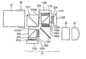
- the light source unit 25 is a high-intensity light source such as an ultra-high pressure mercury lamp, and has an arc tube emitting white light in a continuous spectrum and a reflector for condensing light in a predetermined direction. Irradiate at 26.
- the illumination optical system 26 has a glass member such as a cylinder array, and its optical action forms a rectangular uniform illumination area in which rectangular images are superimposed on a plurality of luminous flux, and color separation of the next step is performed.
- the optical unit 21 which is a synthetic optical system is illuminated.
- the optical unit 21 has a dichroic mirror 1001 that reflects light in the blue (B) and red (R) wavelength ranges and transmits light in the green (G) wavelength range.
- a dichroic mirror 1001 that reflects light in the blue (B) and red (R) wavelength ranges and transmits light in the green (G) wavelength range.
- For light in the green (G) wavelength region there is a half-wave plate 1002, an incident-side polarizing plate 1003 for G in which the polarizing element is attached to a transparent substrate that transmits only S-polarized light, and a polarization separation surface.
- a first polarization beam splitter 23G is provided which transmits p-polarized light and reflects s-polarized light.
- the S-polarized light reflected by the first polarization beam splitter 23G as a prism that splits the optical path is circularly polarized through the green quarter-wave plate 22G, and is mounted on the heat sink 112G. Go to the light valve 111G as an image display element.
- the quarter-wave plate 22G is provided in the optical path between the first polarizing beam splitter 23G and the light valve 111G for green.
- the light reflected by the light valve 111G for green is made to be P-polarized light through the quarter wavelength plate 22G for green. Then, it is transmitted through the first polarization beam splitter 23G and the G-use output side polarizing plate 1010G which transmits only P-polarized light, and travels to the dichroic prism 1011 which transmits RB light and reflects G light.
- an incident side polarizing plate 1006 for RB and a color selective retardation plate 1007 are provided in which only P polarized light is transmitted and the polarizing element is attached to a transparent substrate. It is done. Since the color selective retardation plate 1007 has a function of converting the polarization direction of R light by 90 degrees and not converting the polarization direction of B light, light in the red (R) wavelength region is converted to S polarization. , And light in the blue (B) wavelength region pass as P-polarization.
- a trimming filter 1008 for returning orange light to the lamp is provided in the light path which has passed through the color selective retardation plate 1007 in order to enhance the color purity of R.
- the second polarization beam splitter 23BR as a prism that transmits P-polarization, reflects S-polarization, and splits or combines the light path reflects the light of R which is S-polarization while the light of B which is P-polarization Is transparent.
- the R light reflected by the second polarization beam splitter 23BR is circularly polarized through the red quarter-wave plate 22R, and travels to the red light valve 111R mounted on the heat sink 112R.
- the light reflected by the red light valve 111R is p-polarized through the red quarter-wave plate 22R.
- the second polarizing beam splitters 23BR and B for transmitting only the S-polarized light of B are transmitted through the B-emitting-side polarizing plate (polarizing element) 1010B and the dichroic prism 1011 to enter the projection lens 27 as a projection optical system.
- the B light transmitted through the second polarization beam splitter 23BR is circularly polarized through the blue quarter-wave plate 22B, and travels to the blue light valve 111B mounted on the heat sink 112B. .
- the light reflected by the blue light valve 111B is p-polarized through the blue quarter-wave plate 12B. Then, it is reflected by the second polarization beam splitter 23BR and rectifies only B s-polarized light, and transmits through the B light emission side polarization plate (polarization element) 1010B and the dichroic prism 1011 to the projection lens 27 as a projection optical system. It will be incident.
- Reference numeral 28 denotes lens shift means for shifting the projection lens 27 in the direction orthogonal to the optical axis.
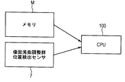
- a lens apparatus includes a projection optical system 27 shown in FIGS. 1A, 1B, 2A, and 2B, a sensor 7 described later, a memory M as a storage unit, and a CPU 100 as a control unit (FIG. 5). ).
- the projection optical system 27 includes the field curvature adjustment group 1 as a first optical unit that changes the amount of curvature of field of the projection optical system by being displaced in the optical axis direction of the projection optical system.
- the zoom adjustment group 3 or the focus adjustment group 2 is provided as a second optical unit that changes the projection magnification or the focal position of the projection optical system by displacing in the optical axis direction of the projection optical system.
- FIGS. 1A, 2A, and 2B are cross-sectional views of a projection optical system including a lens capable of adjusting (changing) curvature of field.
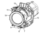
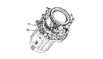
- FIG. 1B, FIG. 3A, FIG. 3B and FIG. 3C show an external appearance.
- the field curvature adjustment group 1 composed of the optical component group (lens group) moves (displaces) in the direction of the optical axis 15 of the projection optical system 27 to make the field curvature of the projection image surface (screen surface) 14
- the degree of (field curvature) can be selected as the planar shape 14a and the spherical shape 14b. In other words, it is possible to change the projection image surface from one of the spherical surface 14 b and the planar surface 14 a to the other by the displacement of the field curvature adjustment group 1.
- the field curvature adjustment group 1 can be moved (displaced) in the direction of the optical axis 15 by manually rotating the field curvature adjustment grip 10 (moving means) (FIG. 1B).
- the field curvature adjustment group 1 includes a lens provided closest to the enlargement conjugate among a plurality of lenses provided in the projection optical system 27. Such a configuration of the field curvature adjustment group 1 is preferable because the field curvature can be positively changed with a simple configuration. Of course, the field curvature adjustment group 1 may be provided on the foremost side and may be configured by only one lens.
- the field curvature adjustment group position detection sensor 7 (FIG. 1B) as a first detection means via the field curvature adjustment group position detection gear 19 (FIG. 3C) integrated with the field curvature adjustment group 1. Give the rotation to).
- the position of the field curvature adjustment group 1 can be detected by the field curvature adjustment group position detection sensor 7. In this way, by setting the projection image surface 14 to 14a to 14b, it is possible to fit to a spherical screen.
- the driving force of the zoom adjustment motor 8 (FIG. 1B) is given to the zoom adjustment cam ring 6 (FIG. 1A) via the zoom drive gear 17 (FIG. 3B). It moves in the direction of the optical axis 15 to change the projection magnification.
- the zoom adjustment group 3 can be detected by the zoom adjustment position detection end detection sensor 12 (FIG. 1B) as a second detection unit.
- FIG. 2A shows the case where the zoom position is WIDE
- FIG. 2B shows the case where the zoom position is TELE.
- the driving force of the focus adjustment motor 9 (FIG. 1B) is given to the focus adjustment cam ring 5 (FIG. 2A) via the focus drive gear 16 (FIG. 3A).
- the focus position is changed.
- the initial position is detected by the focus adjustment position detection end detection sensor 11, and the rotation amount is detected by the focus adjustment group position detection rotation detection sensor 18 which is a photo interrupter. Position detection is possible. In the present embodiment, only the focus adjustment group 2 is moved during focusing, and the field curvature adjustment group 1 is not moved for focusing. Good.
- the fixed group 4 shown in FIG. 1A is a lens group which does not move.
- the amount of movement of the field curvature adjustment group 1 and the amount of fluctuation of the enlargement magnification as change information therefor are stored in advance in the memory M (FIG. 5) provided on the lens control board 13 as storage information. .
- the CPU 100 (FIG. 5) as a control unit detects the amount of movement from the field curvature adjustment group position detection sensor 7 and stored information stored in advance. Based on (variation information of magnification), the following control is performed. That is, the zoom adjustment group 3 is moved (displaced) so as to reduce (cancel) the fluctuation of the enlargement magnification.
- FIG. 6 shows the above control as a flowchart. As described above, by performing control according to the flowchart shown in FIG. 6 by the CPU 100, it is possible to automatically suppress the change in the magnification (angle of view) caused by the curvature of field adjustment.
- the movement amount of the curvature of field adjustment group 1 and the fluctuation amount of the focus position with respect to it are stored in advance in the memory M (FIG. 5) provided on the lens control board 13 as storage information. deep. Then, when the field curvature adjustment group 1 is moved (displaced) in the direction of the optical axis 15, the CPU 100 (FIG. 5) as a controller detects the amount of movement from the field curvature adjustment group position detection sensor 7, The following control is performed from the stored information (variation information of the focus position) stored. That is, the focus adjustment group 2 is moved (displaced) so as to reduce (cancel) the fluctuation of the focus position.
- the fluctuation of the magnification or the fluctuation of the focus position is automatically adjusted when adjusting the curvature of field.
- the fluctuation of the magnification and the fluctuation of the focus position may be automatically adjusted simultaneously.
- the aforementioned memory M further stores the positional relationship between the optical axis of the field curvature adjustment group 1 and the optical axis of the projection optical system 27, and the CPU 100 is based on this positional relationship when adjusting the field curvature.
- the lens shift means 28 may be controlled.
- the position of the field curvature adjustment group 1 and the direction in which the optical axis of the field curvature adjustment group 1 deviates from the optical axis of the projection optical system 27 (shift position information) are stored in the memory M. Then, based on the shift shift information stored in the memory M along with the adjustment of the curvature of field, the shift shift may be canceled by the lens shift means 28. With such a configuration, it is possible to suppress the influence of, for example, a rattling between the cam follower and the cam groove.
- the information stored in advance is the change in magnification or focus position with respect to the amount of movement of the field curvature adjustment group 1, but the adjustment amount of the zoom adjustment group 3 or the adjustment amount of the focus adjustment group 2 is directly You may memorize. In this case, there is no need to calculate the adjustment amount in the CPU 100 as the control unit.
- the CPU 100 reduces the change in the projection magnification or the focal position of the projection optical system based on the position of the first optical unit 1 detected by the sensor 7 and the change information stored in the memory M.
- the second optical units 2 and 3 were displaced.
- the second sensor 12 or 18 for detecting the position of the second optical unit is provided, and the CPU 100 detects the positions of the first and second optical units detected by the sensors 7 and 12 or 18 and the memory M. It may be controlled as follows based on the change information stored in. That is, the second optical units 2 and 3 may be displaced so as to reduce changes in the projection magnification or focal position of the projection optical system.
- the lens apparatus includes the field curvature adjustment group 1 as the first optical unit, the zoom adjustment group 3 or the focus adjustment group 2 as the second optical unit, the sensor 7, the memory M, and the CPU 100.
- a lens apparatus comprising a field curvature adjustment group 1, a zoom adjustment group 3 or a focus adjustment group 2 as a first and a second optical unit, and a sensor 7 can be mounted on the apparatus main body of an image projection apparatus,
- the memory M and the CPU 100 may be provided in the main body of the device.
- the first and second optical units do not include the optical parts overlapping each other, but may include at least one optical part overlapping each other.
- Modification 6 As in the first modification described above, in addition to the configuration that uses lens shift means to suppress the influence of shift shift, color shift that occurs with the adjustment of curvature of field is canceled by electrical correction of the liquid crystal panel. It may be of any configuration. More specifically, pixel misalignment of RGB may be corrected by performing pixel alignment in units smaller than one pixel by electrical correction of the liquid crystal panel.
Abstract
Description
(画像投射装置)
図4は、本発明の実施形態に係るレンズ装置を搭載した画像投射装置としてのプロジェクタの光学構成概略図である。光源部25は、超高圧水銀ランプなどの高輝度光源であって連続スペクトルで白色光を発光する発光管と、光を所定の方向に集光するリフレクタとを有し、次段階の照明光学系26へ向けて照射する。照明光学系26は、シリンダアレイ等のガラス部材を有し、その光学的作用により、複数の光束に対し矩形状の像が重なった矩形状の均一な照明エリアが形成され、次段階の色分離合成光学系である光学部21を照明する。 First Embodiment
(Image projection device)
FIG. 4 is a schematic diagram of an optical configuration of a projector as an image projection apparatus equipped with a lens apparatus according to an embodiment of the present invention. The
以下に、本発明の実施形態に係るレンズ装置を図1A乃至図3Cを用い詳細に説明する。本発明の実施形態に係るレンズ装置は、図1A、図1B、図2A、図2Bに示す投射光学系27と、後述するセンサ7、記憶手段としてのメモリM、制御部としてのCPU100(図5)を備える。そして、投射光学系27は、投射光学系の光軸方向に変位することにより、投射光学系の像面湾曲量を変化させる第1の光学ユニットとしての像面湾曲調整群1を備える。また、投射光学系の光軸方向に変位することにより、投射光学系の投射倍率または焦点位置を変化させる第2の光学ユニットとしてのズーム調整群3またはフォーカス調整群2を備える。 (Lens device)
Hereinafter, a lens apparatus according to an embodiment of the present invention will be described in detail with reference to FIGS. 1A to 3C. A lens apparatus according to an embodiment of the present invention includes a projection
以下、本発明の第2の実施形態について説明する。屈折率が空気とは異なる像面湾曲調整群1を光軸方向15に移動した場合、投射画像の焦点位置(ピント位置)が変動する。このため、像面湾曲を意図的に発生させると同時にピント位置も変動する。 Second Embodiment
Hereinafter, a second embodiment of the present invention will be described. When the field curvature adjustment group 1 having a refractive index different from that of air is moved in the
以上、本発明の好ましい実施形態について説明したが、本発明はこれらの実施形態に限定されず、その要旨の範囲内で種々の変形及び変更が可能である。因みに、本実施形態に記載されている構成部品の機能、形状その相対配置などは、特に特定的な記載がない限りは、この発明の範囲をそれらのみに限定する趣旨のものではない。 (Modification)
As mentioned above, although the preferable embodiment of this invention was described, this invention is not limited to these embodiment, A various deformation | transformation and change are possible within the range of the summary. Incidentally, the functions of components described in the present embodiment, the shapes and their relative positions, and the like are not intended to limit the scope of the present invention to them unless specifically described otherwise.
上述した実施形態では、像面湾曲の調整時に拡大倍率の変動もしくはピント位置の変動を自動調整したが、拡大倍率の変動、ピント位置の変動の双方を同時に自動調整しても良い。また、拡大倍率の変動、ピント位置の変動のみに限らず、レンズシフトの位置やフォーカスポジション、ズームポジションなども自動調整することが可能である。この際、前述のメモリMは像面湾曲調整群1の光軸と投射光学系27の光軸との位置関係をさらに記憶しており、像面湾曲調整の際にCPU100がこの位置関係に基づいてレンズシフト手段28を制御してもよい。より具体的には、像面湾曲調整群1の位置と、その位置における像面湾曲調整群1の光軸と投射光学系27の光軸とのずれ量とずれている方向(シフトずれ情報)をメモリMに記憶しておく。そして、像面湾曲の調整に伴ってメモリMに記憶されたシフトずれ情報を基にレンズシフト手段28でシフトずれをキャンセルしてもよい。このような構成によって、例えばカムフォロアとカム溝との間にあるガタなどによる影響を抑制することができる。 (Modification 1)
In the embodiment described above, the fluctuation of the magnification or the fluctuation of the focus position is automatically adjusted when adjusting the curvature of field. However, the fluctuation of the magnification and the fluctuation of the focus position may be automatically adjusted simultaneously. In addition, it is possible to automatically adjust the position of the lens shift, the focus position, the zoom position, etc., as well as the fluctuation of the enlargement magnification and the fluctuation of the focus position. At this time, the aforementioned memory M further stores the positional relationship between the optical axis of the field curvature adjustment group 1 and the optical axis of the projection
上述した実施形態では、予め記憶する情報として、像面湾曲調整群1の移動量に対する拡大倍率変動もしくはピント位置変動としたが、ズーム調整群3の調整量もしくはフォーカス調整群2の調整量を直接記憶しても良い。この場合、制御部としてのCPU100内で調整量を算出する必要が無くなる。 (Modification 2)
In the embodiment described above, the information stored in advance is the change in magnification or focus position with respect to the amount of movement of the field curvature adjustment group 1, but the adjustment amount of the
上述した実施形態で、CPU100は、センサ7によって検出された第1の光学ユニット1の位置と、メモリMに記憶された変化情報とに基づき、投射光学系の投射倍率または焦点位置の変化を減じるように第2の光学ユニット2、3を変位させた。ここで、第2の光学ユニットの位置を検出する第2のセンサ12または18を設け、CPU100は、センサ7及び12又は18で検出された第1、第2の光学ユニットの位置と、メモリMに記憶された変化情報とに基づき、以下のように制御しても良い。即ち、投射光学系の投射倍率または焦点位置の変化を減じるように第2の光学ユニット2、3を変位させても良い。 (Modification 3)
In the embodiment described above, the
上述した実施形態では、レンズ装置が、第1の光学ユニットとしての像面湾曲調整群1、第2の光学ユニットとしてのズーム調整群3またはフォーカス調整群2、センサ7、メモリM、CPU100を備えることを説明したが、これに限られない。第1、第2の光学ユニットとしての像面湾曲調整群1、ズーム調整群3またはフォーカス調整群2、センサ7を備えるレンズ装置が画像投射装置の装置本体に装着可能であって、画像投射装置の装置本体にメモリM、CPU100を備える構成としても良い。 (Modification 4)
In the embodiment described above, the lens apparatus includes the field curvature adjustment group 1 as the first optical unit, the
上述した実施形態では、第1、第2の光学ユニットは、両者に重複した光学部品を備えないものであったが、両者に重複した光学部品を少なくとも一つ備えるものであっても良い。 (Modification 5)
In the above-described embodiment, the first and second optical units do not include the optical parts overlapping each other, but may include at least one optical part overlapping each other.
上述した変形例1のように、レンズシフト手段を用いてシフトずれによる影響を抑制する構成に加えて、像面湾曲の調整に伴って生じる色ずれを液晶パネルの電気的な補正によってキャンセルするような構成であってもよい。より具体的には、RGBの画素ずれを液晶パネルの電気的な補正によって1画素よりも小さい単位で画素合わせを行って補正してもよい。 (Modification 6)
As in the first modification described above, in addition to the configuration that uses lens shift means to suppress the influence of shift shift, color shift that occurs with the adjustment of curvature of field is canceled by electrical correction of the liquid crystal panel. It may be of any configuration. More specifically, pixel misalignment of RGB may be corrected by performing pixel alignment in units smaller than one pixel by electrical correction of the liquid crystal panel.
2 フォーカス調整群
3 ズーム調整群
7 像面湾曲調整群位置検出センサ
27 投射光学系
100 CPU
M メモリ
Reference Signs List 1 field
M memory
Claims (13)
- 投射光学系の光軸方向に変位することにより、前記投射光学系の像面湾曲量を変化させる第1の光学ユニットと、
前記投射光学系の光軸方向に変位することにより、前記投射光学系の投射倍率または焦点位置を変化させる第2の光学ユニットと、
前記第1の光学ユニットの位置を検出する第1の検出手段と、
前記第1の光学ユニットの変位による、前記投射光学系の投射倍率または焦点位置の変化に関する変化情報を記憶するメモリと、
前記第1の検出手段によって検出された前記第1の光学ユニットの位置と、前記メモリに記憶された前記変化情報とに基づいて、前記第1の光学ユニットの変位に伴う前記投射光学系の投射倍率または焦点位置の変化を減じるように前記第2の光学ユニットを変位させる制御部と、
を有することを特徴とするレンズ装置。 A first optical unit that changes an amount of curvature of field of the projection optical system by displacing in a direction of an optical axis of the projection optical system;
A second optical unit that changes a projection magnification or a focal position of the projection optical system by displacing in a direction of an optical axis of the projection optical system;
First detection means for detecting the position of the first optical unit;
A memory for storing change information regarding a change in projection magnification or focal position of the projection optical system due to displacement of the first optical unit;
The projection of the projection optical system according to the displacement of the first optical unit based on the position of the first optical unit detected by the first detection means and the change information stored in the memory A control unit for displacing the second optical unit so as to reduce a change in magnification or focal position;
A lens apparatus characterized by having: - 前記第2の光学ユニットの位置を検出する第2の検出手段を有し、前記制御部は、前記第1の検出手段によって検出された前記第1の光学ユニットの位置と、前記第2の検出手段によって検出された前記第2の光学ユニットの位置と、前記メモリに記憶された前記変化情報とに基づいて、前記第1の光学ユニットの変位に伴う前記投射光学系の投射倍率または焦点位置の変化を減じるように前記第2の光学ユニットを変位させることを特徴とする請求項1に記載のレンズ装置。 And a second detection unit that detects the position of the second optical unit, wherein the control unit detects the position of the first optical unit detected by the first detection unit, and the second detection. Of the projection optical system or the focal position of the projection optical system according to the displacement of the first optical unit based on the position of the second optical unit detected by the means and the change information stored in the memory The lens apparatus according to claim 1, wherein the second optical unit is displaced to reduce a change.
- 前記第1の光学ユニットの変位によって、前記投射光学系の投射面を、球面状と平面状のうち一方から他方へ変化させることが可能であることを特徴とする請求項1または2に記載のレンズ装置。 The displacement of the first optical unit makes it possible to change the projection surface of the projection optical system from one of spherical and planar to the other. Lens device.
- 前記第1、第2の光学ユニットの両者に重複した光学部品が無いことを特徴とする請求項1乃至3のいずれか1項に記載のレンズ装置。 The lens apparatus according to any one of claims 1 to 3, wherein there is no optical component overlapping both of the first and second optical units.
- 前記第2の光学ユニットは、フォーカシング時に移動するフォーカス調整群と、ズーミング時に移動するズーム調整群とを備え、
前記第1の光学ユニットは、前記フォーカシングのためには移動せず、像面湾曲の調整の際に移動することを特徴とする請求項4に記載のレンズ装置。 The second optical unit includes a focus adjustment group that moves during focusing, and a zoom adjustment group that moves during zooming.
5. The lens apparatus according to claim 4, wherein the first optical unit does not move for the focusing but moves when adjusting the curvature of field. - 前記第1、第2の光学ユニットは、両者に重複した光学部品を少なくとも一つ備えることを特徴とする請求項1乃至3のいずれか1項に記載のレンズ装置。 The lens apparatus according to any one of claims 1 to 3, wherein the first and second optical units include at least one optical component overlapping each other.
- 前記第1の光学ユニットを前記投射光学系の光軸方向に移動させるとともに、ユーザーが操作可能な移動手段を有することを特徴とする請求項1乃至6のいずれか1項に記載のレンズ装置。 The lens apparatus according to any one of claims 1 to 6, further comprising moving means operable to move the first optical unit in the optical axis direction of the projection optical system and operable by the user.
- 前記レンズ装置は、複数のレンズを備え、
前記第1の光学ユニットは、前記複数のレンズのうち最も拡大共役側に位置するレンズを含むことを特徴とする請求項1乃至7のいずれか1項に記載のレンズ装置。 The lens arrangement comprises a plurality of lenses,
The lens apparatus according to any one of claims 1 to 7, wherein the first optical unit includes a lens located closest to the magnification conjugate side among the plurality of lenses. - 前記メモリは、前記第1の光学ユニットの光軸と前記投射光学系の光軸との位置関係をさらに記憶しており、
前記制御部は、前記位置関係に基づいて少なくとも前記第1の光学ユニットを前記光軸方向と直交する方向にシフトさせることを特徴とする請求項1乃至8のいずれか1項に記載のレンズ装置。 The memory further stores the positional relationship between the optical axis of the first optical unit and the optical axis of the projection optical system,
The lens apparatus according to any one of claims 1 to 8, wherein the control unit shifts at least the first optical unit in a direction orthogonal to the optical axis direction based on the positional relationship. . - 画像表示素子と、
請求項1乃至9のいずれか1項に記載のレンズ装置と、
を有することを特徴とする画像投射装置。 An image display element,
A lens apparatus according to any one of the preceding claims.
An image projection apparatus characterized by having: - 投射光学系の光軸方向に変位することにより、前記投射光学系の像面湾曲量を変化させる第1の光学ユニットと、
前記投射光学系の光軸方向に変位することにより、前記投射光学系の投射倍率または焦点位置を変化させる第2の光学ユニットと、
前記第1の光学ユニットの位置を検出する第1の検出手段と、
を備えるレンズ装置を装着可能な画像投射装置であって、
前記第1の光学ユニットの変位による、前記投射光学系の投射倍率または焦点位置の変化に関する変化情報を記憶するメモリと、
前記第1の検出手段によって検出された前記第1の光学ユニットの位置と、前記メモリに記憶された前記変化情報とに基づいて、前記第1の光学ユニットの変位に伴う前記投射光学系の投射倍率または焦点位置の変化を減じるように前記第2の光学ユニットを変位させる制御部と、
を有することを特徴とする画像投射装置。 A first optical unit that changes an amount of curvature of field of the projection optical system by displacing in a direction of an optical axis of the projection optical system;
A second optical unit that changes a projection magnification or a focal position of the projection optical system by displacing in a direction of an optical axis of the projection optical system;
First detection means for detecting the position of the first optical unit;
An image projection apparatus capable of mounting a lens apparatus having the
A memory for storing change information regarding a change in projection magnification or focal position of the projection optical system due to displacement of the first optical unit;
The projection of the projection optical system according to the displacement of the first optical unit based on the position of the first optical unit detected by the first detection means and the change information stored in the memory A control unit for displacing the second optical unit so as to reduce a change in magnification or focal position;
An image projection apparatus characterized by having: - 前記第1の光学ユニットの変位によって、前記投射光学系の投射面を、球面状と平面状のうち一方から他方へ変化させることが可能であることを特徴とする請求項11に記載の画像投射装置。 The image projection according to claim 11, wherein the projection surface of the projection optical system can be changed from one of spherical and planar to the other by displacement of the first optical unit. apparatus.
- 前記メモリは、前記第1の光学ユニットの光軸と前記投射光学系の光軸との位置関係をさらに記憶しており、
前記レンズ装置を前記光軸方向と直交する方向に移動させることが可能なレンズシフト手段をさらに備え、
前記制御部は、前記位置関係に基づいて前記レンズシフト手段を制御することを特徴とする請求項11または12に記載の画等投射装置。
The memory further stores the positional relationship between the optical axis of the first optical unit and the optical axis of the projection optical system,
It further comprises lens shift means capable of moving the lens device in a direction orthogonal to the optical axis direction,
13. The image projection apparatus according to claim 11, wherein the control unit controls the lens shift unit based on the positional relationship.
Priority Applications (5)
| Application Number | Priority Date | Filing Date | Title |
|---|---|---|---|
| EP16742983.6A EP3229055B1 (en) | 2015-01-29 | 2016-01-27 | Lens device and image projection device |
| RU2017129815A RU2662487C1 (en) | 2015-01-29 | 2016-01-27 | Lens device and image project device |
| CN201680007052.9A CN107209344B (en) | 2015-01-29 | 2016-01-27 | Lens devices and image projection device |
| JP2016571866A JPWO2016121379A1 (en) | 2015-01-29 | 2016-01-27 | Lens device and image projection device |
| US15/646,420 US10324364B2 (en) | 2015-01-29 | 2017-07-11 | Lens apparatus and image projection apparatus |
Applications Claiming Priority (2)
| Application Number | Priority Date | Filing Date | Title |
|---|---|---|---|
| JP2015-015283 | 2015-01-29 | ||
| JP2015015283 | 2015-01-29 |
Related Child Applications (1)
| Application Number | Title | Priority Date | Filing Date |
|---|---|---|---|
| US15/646,420 Continuation US10324364B2 (en) | 2015-01-29 | 2017-07-11 | Lens apparatus and image projection apparatus |
Publications (1)
| Publication Number | Publication Date |
|---|---|
| WO2016121379A1 true WO2016121379A1 (en) | 2016-08-04 |
Family
ID=56543001
Family Applications (1)
| Application Number | Title | Priority Date | Filing Date |
|---|---|---|---|
| PCT/JP2016/000385 WO2016121379A1 (en) | 2015-01-29 | 2016-01-27 | Lens device and image projection device |
Country Status (6)
| Country | Link |
|---|---|
| US (1) | US10324364B2 (en) |
| EP (1) | EP3229055B1 (en) |
| JP (1) | JPWO2016121379A1 (en) |
| CN (1) | CN107209344B (en) |
| RU (1) | RU2662487C1 (en) |
| WO (1) | WO2016121379A1 (en) |
Cited By (3)
| Publication number | Priority date | Publication date | Assignee | Title |
|---|---|---|---|---|
| JP2018054910A (en) * | 2016-09-29 | 2018-04-05 | 富士フイルム株式会社 | Imaging lens and optical device |
| JP2018063421A (en) * | 2016-10-11 | 2018-04-19 | キヤノン株式会社 | Lens device and image projection device using the same |
| JP2019184804A (en) * | 2018-04-10 | 2019-10-24 | キヤノン株式会社 | Image projection apparatus and program |
Families Citing this family (8)
| Publication number | Priority date | Publication date | Assignee | Title |
|---|---|---|---|---|
| RU2662487C1 (en) | 2015-01-29 | 2018-07-26 | Кэнон Кабусики Кайся | Lens device and image project device |
| US10036940B2 (en) * | 2016-10-11 | 2018-07-31 | Canon Kabushiki Kaisha | Lens apparatus and image projector using the same |
| JP2020112660A (en) * | 2019-01-10 | 2020-07-27 | キヤノン株式会社 | Projection device and program |
| US20220057595A1 (en) * | 2019-04-12 | 2022-02-24 | Ricoh Industrial Solutions Inc. | Lens barrel and image projection apparatus |
| US11320725B2 (en) * | 2019-11-22 | 2022-05-03 | Canon Kabushiki Kaisha | Projection type display apparatus, projection type display system, control method of projection type display apparatus, and storage medium |
| DE102020109190A1 (en) * | 2020-04-02 | 2021-10-07 | Arnold & Richter Cine Technik Gmbh & Co. Betriebs Kg | Headlight system, headlight, optical component therefor and method for determining a spatial light distribution of the same |
| CN213957809U (en) * | 2020-11-06 | 2021-08-13 | 深圳市爱图仕影像器材有限公司 | Lamp and optical lens thereof |
| CN114077144B (en) * | 2021-08-13 | 2024-04-02 | 深圳市安华光电技术股份有限公司 | Automatic focusing lens for projector and projector |
Citations (5)
| Publication number | Priority date | Publication date | Assignee | Title |
|---|---|---|---|---|
| JP2011145580A (en) * | 2010-01-18 | 2011-07-28 | Seiko Epson Corp | Projector |
| JP2012093553A (en) * | 2010-10-27 | 2012-05-17 | Sharp Corp | Image projecting device, image projecting method and control program for image projecting devices |
| JP2012194226A (en) * | 2011-03-15 | 2012-10-11 | Seiko Epson Corp | Projector and control method of the same |
| JP2013109186A (en) * | 2011-11-22 | 2013-06-06 | Canon Inc | Projection type display device |
| JP2015230320A (en) * | 2014-06-03 | 2015-12-21 | キヤノン株式会社 | Lens device and optical device |
Family Cites Families (12)
| Publication number | Priority date | Publication date | Assignee | Title |
|---|---|---|---|---|
| US3475086A (en) * | 1966-02-10 | 1969-10-28 | D 150 Inc | Cinema system utilizing a deeply curved screen and a mask for providing an illusion |
| JP2773820B2 (en) * | 1987-06-08 | 1998-07-09 | 富士写真光機株式会社 | Field curvature correction device for zoom lens |
| JP2979844B2 (en) * | 1992-05-01 | 1999-11-15 | キヤノン株式会社 | Imaging device having adjustment mechanism |
| JP3433266B2 (en) * | 1993-06-15 | 2003-08-04 | 三菱電機株式会社 | Projection lens |
| EP1530071B1 (en) * | 2003-11-06 | 2016-02-17 | Canon Kabushiki Kaisha | Zoom lens and image taking system |
| JP2005300662A (en) * | 2004-04-07 | 2005-10-27 | Seiko Epson Corp | Rear projector |
| US8521411B2 (en) * | 2004-06-03 | 2013-08-27 | Making Virtual Solid, L.L.C. | En-route navigation display method and apparatus using head-up display |
| JP2007121770A (en) | 2005-10-28 | 2007-05-17 | Fujifilm Corp | Lens device, lens adjustment device and camera |
| JP5168783B2 (en) * | 2005-12-27 | 2013-03-27 | カシオ計算機株式会社 | Projection apparatus, projection method, and program |
| US20120320257A1 (en) * | 2011-06-17 | 2012-12-20 | Gal Shabtay | Auto-focus actuator for field curvature correction of zoom lenses |
| JP2014235217A (en) * | 2013-05-31 | 2014-12-15 | 富士フイルム株式会社 | Projection lens and projection type display device |
| RU2662487C1 (en) | 2015-01-29 | 2018-07-26 | Кэнон Кабусики Кайся | Lens device and image project device |
-
2016
- 2016-01-27 RU RU2017129815A patent/RU2662487C1/en active
- 2016-01-27 WO PCT/JP2016/000385 patent/WO2016121379A1/en active Application Filing
- 2016-01-27 CN CN201680007052.9A patent/CN107209344B/en active Active
- 2016-01-27 EP EP16742983.6A patent/EP3229055B1/en active Active
- 2016-01-27 JP JP2016571866A patent/JPWO2016121379A1/en active Pending
-
2017
- 2017-07-11 US US15/646,420 patent/US10324364B2/en active Active
Patent Citations (5)
| Publication number | Priority date | Publication date | Assignee | Title |
|---|---|---|---|---|
| JP2011145580A (en) * | 2010-01-18 | 2011-07-28 | Seiko Epson Corp | Projector |
| JP2012093553A (en) * | 2010-10-27 | 2012-05-17 | Sharp Corp | Image projecting device, image projecting method and control program for image projecting devices |
| JP2012194226A (en) * | 2011-03-15 | 2012-10-11 | Seiko Epson Corp | Projector and control method of the same |
| JP2013109186A (en) * | 2011-11-22 | 2013-06-06 | Canon Inc | Projection type display device |
| JP2015230320A (en) * | 2014-06-03 | 2015-12-21 | キヤノン株式会社 | Lens device and optical device |
Cited By (5)
| Publication number | Priority date | Publication date | Assignee | Title |
|---|---|---|---|---|
| JP2018054910A (en) * | 2016-09-29 | 2018-04-05 | 富士フイルム株式会社 | Imaging lens and optical device |
| JP2018063421A (en) * | 2016-10-11 | 2018-04-19 | キヤノン株式会社 | Lens device and image projection device using the same |
| JP6991797B2 (en) | 2016-10-11 | 2022-01-13 | キヤノン株式会社 | Lens device and image projection device using it |
| JP2019184804A (en) * | 2018-04-10 | 2019-10-24 | キヤノン株式会社 | Image projection apparatus and program |
| JP7080701B2 (en) | 2018-04-10 | 2022-06-06 | キヤノン株式会社 | Image projectors and programs |
Also Published As
| Publication number | Publication date |
|---|---|
| CN107209344A (en) | 2017-09-26 |
| US10324364B2 (en) | 2019-06-18 |
| JPWO2016121379A1 (en) | 2017-11-09 |
| EP3229055A1 (en) | 2017-10-11 |
| EP3229055A4 (en) | 2018-05-30 |
| RU2662487C1 (en) | 2018-07-26 |
| CN107209344B (en) | 2019-07-23 |
| US20170307966A1 (en) | 2017-10-26 |
| EP3229055B1 (en) | 2019-04-24 |
Similar Documents
| Publication | Publication Date | Title |
|---|---|---|
| WO2016121379A1 (en) | Lens device and image projection device | |
| US9664376B2 (en) | Projection-type image display apparatus | |
| JP5381363B2 (en) | projector | |
| US7384157B2 (en) | Projection type video display | |
| WO2012046575A1 (en) | Projection video display device | |
| US20110128503A1 (en) | Stereoscopic image projector | |
| JP5217630B2 (en) | Projector and multi-projection system | |
| JP2007079401A (en) | Projector | |
| JP2016109823A (en) | Lens device and projection display device | |
| JP2007150816A (en) | Projector | |
| JP2003207740A (en) | Video light generation optical unit and back projection type video display | |
| JP5105774B2 (en) | Projection display | |
| JP2005345604A (en) | Projection-type display device | |
| JP4412932B2 (en) | Projection-type image display device and method for adjusting the device at the time of shipment | |
| JP2017032891A (en) | Projector, focus correct method, and program | |
| JP2007328086A (en) | Projection optical system and projector | |
| JP2015049272A (en) | Projection type display device | |
| JP4315890B2 (en) | Projection display device | |
| JP2018031932A (en) | Optical device | |
| JP2012042780A (en) | Projector | |
| JP6335772B2 (en) | Projection display device | |
| JP2016114667A (en) | Lens device, projection type display device using the same, and lens device control method | |
| KR100826356B1 (en) | Projector | |
| JP4978395B2 (en) | Optical device manufacturing method | |
| JP2006003407A (en) | Projector |
Legal Events
| Date | Code | Title | Description |
|---|---|---|---|
| 121 | Ep: the epo has been informed by wipo that ep was designated in this application |
Ref document number: 16742983 Country of ref document: EP Kind code of ref document: A1 |
|
| ENP | Entry into the national phase |
Ref document number: 2016571866 Country of ref document: JP Kind code of ref document: A |
|
| REEP | Request for entry into the european phase |
Ref document number: 2016742983 Country of ref document: EP |
|
| NENP | Non-entry into the national phase |
Ref country code: DE |
|
| ENP | Entry into the national phase |
Ref document number: 2017129815 Country of ref document: RU Kind code of ref document: A |