WO2016119828A1 - Gas/air mixer assembly for use in a gas burner - Google Patents
Gas/air mixer assembly for use in a gas burner Download PDFInfo
- Publication number
- WO2016119828A1 WO2016119828A1 PCT/EP2015/051645 EP2015051645W WO2016119828A1 WO 2016119828 A1 WO2016119828 A1 WO 2016119828A1 EP 2015051645 W EP2015051645 W EP 2015051645W WO 2016119828 A1 WO2016119828 A1 WO 2016119828A1
- Authority
- WO
- WIPO (PCT)
- Prior art keywords
- gas
- tube
- mixer assembly
- main body
- nozzle device
- Prior art date
- Legal status (The legal status is an assumption and is not a legal conclusion. Google has not performed a legal analysis and makes no representation as to the accuracy of the status listed.)
- Ceased
Links
Images





Classifications
-
- F—MECHANICAL ENGINEERING; LIGHTING; HEATING; WEAPONS; BLASTING
- F23—COMBUSTION APPARATUS; COMBUSTION PROCESSES
- F23D—BURNERS
- F23D14/00—Burners for combustion of a gas, e.g. of a gas stored under pressure as a liquid
- F23D14/46—Details
- F23D14/62—Mixing devices; Mixing tubes
- F23D14/64—Mixing devices; Mixing tubes with injectors
-
- B—PERFORMING OPERATIONS; TRANSPORTING
- B01—PHYSICAL OR CHEMICAL PROCESSES OR APPARATUS IN GENERAL
- B01F—MIXING, e.g. DISSOLVING, EMULSIFYING OR DISPERSING
- B01F23/00—Mixing according to the phases to be mixed, e.g. dispersing or emulsifying
- B01F23/10—Mixing gases with gases
-
- B—PERFORMING OPERATIONS; TRANSPORTING
- B01—PHYSICAL OR CHEMICAL PROCESSES OR APPARATUS IN GENERAL
- B01F—MIXING, e.g. DISSOLVING, EMULSIFYING OR DISPERSING
- B01F25/00—Flow mixers; Mixers for falling materials, e.g. solid particles
- B01F25/30—Injector mixers
- B01F25/31—Injector mixers in conduits or tubes through which the main component flows
- B01F25/312—Injector mixers in conduits or tubes through which the main component flows with Venturi elements; Details thereof
- B01F25/3124—Injector mixers in conduits or tubes through which the main component flows with Venturi elements; Details thereof characterised by the place of introduction of the main flow
- B01F25/31243—Eductor or eductor-type venturi, i.e. the main flow being injected through the venturi with high speed in the form of a jet
-
- B—PERFORMING OPERATIONS; TRANSPORTING
- B01—PHYSICAL OR CHEMICAL PROCESSES OR APPARATUS IN GENERAL
- B01F—MIXING, e.g. DISSOLVING, EMULSIFYING OR DISPERSING
- B01F25/00—Flow mixers; Mixers for falling materials, e.g. solid particles
- B01F25/30—Injector mixers
- B01F25/31—Injector mixers in conduits or tubes through which the main component flows
- B01F25/312—Injector mixers in conduits or tubes through which the main component flows with Venturi elements; Details thereof
- B01F25/3125—Injector mixers in conduits or tubes through which the main component flows with Venturi elements; Details thereof characteristics of the Venturi parts
- B01F25/31252—Nozzles
- B01F25/312521—Adjustable Venturi nozzle
-
- F—MECHANICAL ENGINEERING; LIGHTING; HEATING; WEAPONS; BLASTING
- F23—COMBUSTION APPARATUS; COMBUSTION PROCESSES
- F23N—REGULATING OR CONTROLLING COMBUSTION
- F23N3/00—Regulating air supply or draught
- F23N3/007—Regulating air supply or draught using mechanical means
-
- F—MECHANICAL ENGINEERING; LIGHTING; HEATING; WEAPONS; BLASTING
- F23—COMBUSTION APPARATUS; COMBUSTION PROCESSES
- F23D—BURNERS
- F23D2203/00—Gaseous fuel burners
- F23D2203/007—Mixing tubes, air supply regulation
Definitions
- the present invention relates to a mixer assembly for mixing gas and ambient air for use in the gas burner of a gas cooking appliance.
- Flammable gases such as liquefied petroleum gas (butane, propane) or natural gas (methane) have different number of hydrogen and carbon atoms. Therefore, these gases release different amount of energies when they are combusted. As a rule, the heavier the gas the more energy is released during the combustion. A minimum amount of oxygen is necessary for totally combusting a gas with ideally zero emission of residual pollutants. Therefore, the oxygen to gas (stoichiometric) ratio for the complete combustion differs for different type of gases.
- a mixer assembly is utilized for mixing the inflowing gas with the correct amount of ambient air so as to obtain the proper mixture of gas and oxygen. To meet these requirements, the prior art gas cooking appliance is usually manufactured for operation with only one type of gas. However, some gas cooking appliances are also manufactured to allow conversion from one type of gas to the other type of gas provided that the necessary modifications are performed by a service person. Such modifications involve, among others, the adjustment of the mixer assembly.
- Fig. 1 shows a prior art gas burner (2 ⁇ ) which has a mixer assembly (1 ⁇ ) for mixing gas and ambient air.
- the prior art mixer assembly (1 ⁇ ) comprises: a main body (3 ⁇ ); a nozzle device (4 ⁇ ) for ejecting gas, wherein the nozzle device (4 ⁇ ) is fixed to main body (3 ⁇ ); a tube (5 ⁇ ) for mixing gas and ambient air, wherein the tube (5 ⁇ ) comprises: an outlet for discharging the mixture of gas and ambient air to the gas burner (2 ⁇ ) and an inlet (6 ⁇ ) for jointly admitting the ambient air and the ejected gas into the tube (5 ⁇ ), wherein the tube (5 ⁇ ) is axially slidably disposed onto the main body (3 ⁇ ) so as to vary an axial distance between the inlet (6 ⁇ ) and the nozzle device (4 ⁇ ) and a fixing device (7 ⁇ ) for securing the tube (5 ⁇ ) to the main body (3 ⁇ ).
- the axial distance between the inlet (6 ⁇ ) and the nozzle device (4 ⁇ ) is manually adjusted by the operator.
- the main body (3 ⁇ ) and tube (5 ⁇ ) have adjustment markings (not shown).
- the operator moves the tube (5 ⁇ ) until the markings coincide. Thereafter, the operator secures the tube (5 ⁇ ) through the fixing device (7 ⁇ ), such as a fixing screw.
- a problem with the prior art mixer assembly (1 ⁇ ) is that the adjustment during the manufacturing process or as the case may be during the maintenance is very time consuming and vulnerable to errors which are likely to be introduced by the operator or the service person. If the mixer assembly (1 ⁇ ) is not properly adjusted, the combustion efficiency degrades and the amount of heat released by the gas burner (2 ⁇ ) decreases. Moreover, in case of an incomplete combustion, the harmful emission of carbon monoxide and hydrocarbons such as soot increases. Such harmful emission pollutes the environment and poses a risk to the health of the customer, particularly when the emission limits are exceeded.
- An objective of the present invention is to provide a mixer assembly for mixing gas and ambient air for use in the gas burner of a gas cooking appliance which overcomes the aforementioned drawbacks of the prior art in a cost-effective way and which enables a quick and reliable adjustment of the desired mixing ratio of gas and ambient air and also a quick and reliable conversion from liquefied petroleum gas (LPG) to natural gas or vice versa.
- LPG liquefied petroleum gas
- the mixer assembly of the present invention comprises an adjustment device for adjusting a mixing ratio of the gas and the ambient air by way of blocking a forward movement of the tube at a predetermined axial distance between the inlet and the nozzle device.
- the mixer assembly of the present invention With the mixer assembly of the present invention, the use of the adjustment markings has been obviated and both the manufacturing process and the maintenance have been expedited. Thus, the error introduced by the operator during the manufacturing process and the maintenance due to the manual adjustment involving the use of markings has been eliminated.
- the mixer assembly of the present invention With the mixer assembly of the present invention, the desired mixing ratio of the gas and the ambient air can be quickly and exactly adjusted. Thereby, the combustion efficiency has been improved and the harmful emission of carbon monoxide and hydrocarbons such as soot has been effectively reduced. Also the serviceability has been improved. Thus, the service person can quickly and reliably convert from LPG to natural gas or vice versa by performing the correct adjustment in accordance with the type of gas to be used.
- the forward movement of the tube is blocked by an abutment piece at said predetermined axial distance, which is fixed to the main body.
- abutment piece at said predetermined axial distance, which is fixed to the main body.
- the abutment piece has an integral washer which is fixed between the joining surfaces of the threadably connected nozzle device and the main body respectively.
- the abutment piece can be easily and quickly fixed to the main body.
- the nozzle device and the abutment piece can be easily exchanged or replaced.
- the nozzle device and the abutment piece, including the integral washer are respectively made from brass and Aluminum.
- the thermal expansion coefficient of Aluminum is higher than the thermal expansion coefficient of brass.
- the hardness of brass is higher than the hardness of Aluminum.
- the present invention also provides a gas burner which has a mixer assembly according to present invention.
- the present invention also provides a gas cooking appliance which has at least one gas burner according to present invention.
- Figure 1 – is a schematic perspective view of a gas burner which has a mixer assembly according to the prior art
- Figure 2 – is a schematic perspective view of a gas burner which has a mixer assembly according to an embodiment of the present invention
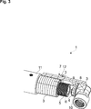
- Figure 3 – is a schematic enlarged partial perspective view of the gas burner which has the mixer assembly according to an embodiment of the present invention
- Figure 4 – is a schematic enlarged perspective view of an adjustment device which is used in the mixer assembly according to an embodiment of the present invention
- Figure 5 – is a schematic enlarged partial perspective view of the gas burner which has the mixer assembly according to an embodiment of the present invention, prior to mounting the tube, the adjustment device and the nozzle device;
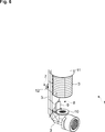
- Figure 6 – is a schematic enlarged partial perspective view of the gas burner which has the mixer assembly according to an embodiment of the present invention, prior to mounting the nozzle device, wherein the tube has been omitted for ease of illustration;
- Figure 7 – is a schematic enlarged partial perspective view of the gas burner which has the mixer assembly according to an embodiment of the present invention, after having mounted the adjustment device and the nozzle device, wherein the tube has been omitted for ease of illustration.
- the mixer assembly (1) is suitable for mixing gas and ambient air for use in the gas burner (2) of a gas cooking appliance (not shown).
- the mixer assembly (1) comprises: a main body (3); a nozzle device (4) for ejecting gas, wherein the nozzle device (4) is fixed to main body (3); a tube (5) for mixing the gas and the ambient air, wherein the tube (5) comprises: an outlet (not shown) for discharging the mixture of the gas and the ambient air to the gas burner (2) and an inlet (6) for jointly admitting the ambient air and the ejected gas into the tube (5), wherein the tube (5) is axially slidably disposed onto the main body (3) so as to vary an axial distance between the inlet (6) and the nozzle device (4) and a fixing device (7) for securing the tube (5) to the main body (3) (Fig. 2 to 7).
- the mixer assembly (1) of the present invention further comprises an adjustment device (8) for adjusting a mixing ratio of the gas and the ambient air by way of blocking a forward movement of the tube (5) at a predetermined axial distance between the inlet (6) and the nozzle device (4).
- the gas burner (2) of the present invention comprises the mixer assembly (1).
- the mixer assembly (1) is assembled with the gas burner (2) such that the outlet of the mixer assembly (1) is fluidly connected to the intake (11) of the gas burner (2).
- the gas cooking appliance of the present invention comprises one or more than one gas burner (2).
- the adjustment device (8) comprises an abutment piece (9) which blocks the forward movement of the tube (5) at said predetermined axial distance.
- the abutment piece (9) is fixed to the main body (3).
- the nozzle device (4) is fixed to the main body (3) by means of a threaded connection.
- the abutment piece (9) has an integral washer (10) which is fixed between the joining surfaces of the nozzle device (4) and the main body (3) respectively.
- the nozzle device (4) is made from brass.
- the abutment piece (9), including the integral washer (10) is made from Aluminum.
- the fixing device (7) comprises a fixing screw (12) for fixing the tube (5) to main body (3) after the adjustment operation.
Landscapes
- Engineering & Computer Science (AREA)
- Chemical & Material Sciences (AREA)
- Chemical Kinetics & Catalysis (AREA)
- Combustion & Propulsion (AREA)
- Mechanical Engineering (AREA)
- General Engineering & Computer Science (AREA)
- Gas Burners (AREA)
Abstract
The present invention relates to a gas/air mixer assembly (1) for use in a gas burner (2). The mixer assembly (1) comprises a main body (3); a nozzle device (4) for ejecting gas; a gas/air mixing tube (5), wherein the tube (5) comprises: an outlet for discharging the mixture to the gas burner (2) and an inlet (6) for jointly admitting the air and the ejected gas, wherein the tube (5) is axially slidably disposed onto the main body (3) so as to vary an axial distance between the inlet (6) and the nozzle device (4) and a fixing device (7) for securing the tube (5). An adjustment device (8) is provided for adjusting a mixing ratio of the gas and the ambient air by way of blocking a forward movement of the tube (5) at a predetermined axial distance between the inlet (6) and the nozzle device (4).
Description
The present invention relates to a mixer assembly for mixing gas and ambient air for use in the gas burner of a gas cooking appliance.
Flammable gases such as liquefied petroleum gas (butane, propane) or natural gas (methane) have different number of hydrogen and carbon atoms. Therefore, these gases release different amount of energies when they are combusted. As a rule, the heavier the gas the more energy is released during the combustion. A minimum amount of oxygen is necessary for totally combusting a gas with ideally zero emission of residual pollutants. Therefore, the oxygen to gas (stoichiometric) ratio for the complete combustion differs for different type of gases. In a prior art gas cooking appliance generally a mixer assembly is utilized for mixing the inflowing gas with the correct amount of ambient air so as to obtain the proper mixture of gas and oxygen. To meet these requirements, the prior art gas cooking appliance is usually manufactured for operation with only one type of gas. However, some gas cooking appliances are also manufactured to allow conversion from one type of gas to the other type of gas provided that the necessary modifications are performed by a service person. Such modifications involve, among others, the adjustment of the mixer assembly.
Fig. 1 shows a prior art gas burner (2´) which has a mixer assembly (1´) for mixing gas and ambient air. The prior art mixer assembly (1´) comprises: a main body (3´); a nozzle device (4´) for ejecting gas, wherein the nozzle device (4´) is fixed to main body (3´); a tube (5´) for mixing gas and ambient air, wherein the tube (5´) comprises: an outlet for discharging the mixture of gas and ambient air to the gas burner (2´) and an inlet (6´) for jointly admitting the ambient air and the ejected gas into the tube (5´), wherein the tube (5´) is axially slidably disposed onto the main body (3´) so as to vary an axial distance between the inlet (6´) and the nozzle device (4´) and a fixing device (7´) for securing the tube (5´) to the main body (3´). In the prior art mixer assembly (1´), the axial distance between the inlet (6´) and the nozzle device (4´) is manually adjusted by the operator. In the prior art mixer assembly (1´), the main body (3´) and tube (5´) have adjustment markings (not shown). For adjusting the mixing ratio of the gas and the ambient air, the operator moves the tube (5´) until the markings coincide. Thereafter, the operator secures the tube (5´) through the fixing device (7´), such as a fixing screw.
A problem with the prior art mixer assembly (1´) is that the adjustment during the manufacturing process or as the case may be during the maintenance is very time consuming and vulnerable to errors which are likely to be introduced by the operator or the service person. If the mixer assembly (1´) is not properly adjusted, the combustion efficiency degrades and the amount of heat released by the gas burner (2´) decreases. Moreover, in case of an incomplete combustion, the harmful emission of carbon monoxide and hydrocarbons such as soot increases. Such harmful emission pollutes the environment and poses a risk to the health of the customer, particularly when the emission limits are exceeded.
An objective of the present invention is to provide a mixer assembly for mixing gas and ambient air for use in the gas burner of a gas cooking appliance which overcomes the aforementioned drawbacks of the prior art in a cost-effective way and which enables a quick and reliable adjustment of the desired mixing ratio of gas and ambient air and also a quick and reliable conversion from liquefied petroleum gas (LPG) to natural gas or vice versa.
This objective has been achieved by the mixer assembly as defined in claim 1, the gas burner as defined in claim 5 and the gas cooking appliance as defined in claim 6. Further achievements have been attained by the subject-matters respectively defined in the dependent claims.
The mixer assembly of the present invention comprises an adjustment device for adjusting a mixing ratio of the gas and the ambient air by way of blocking a forward movement of the tube at a predetermined axial distance between the inlet and the nozzle device.
With the mixer assembly of the present invention, the use of the adjustment markings has been obviated and both the manufacturing process and the maintenance have been expedited. Thus, the error introduced by the operator during the manufacturing process and the maintenance due to the manual adjustment involving the use of markings has been eliminated. With the mixer assembly of the present invention, the desired mixing ratio of the gas and the ambient air can be quickly and exactly adjusted. Thereby, the combustion efficiency has been improved and the harmful emission of carbon monoxide and hydrocarbons such as soot has been effectively reduced. Also the serviceability has been improved. Thus, the service person can quickly and reliably convert from LPG to natural gas or vice versa by performing the correct adjustment in accordance with the type of gas to be used.
In an embodiment, the forward movement of the tube is blocked by an abutment piece at said predetermined axial distance, which is fixed to the main body. In the present invention different abutment pieces can be utilized in accordance with the type of adjustment to be made.
In another embodiment, the abutment piece has an integral washer which is fixed between the joining surfaces of the threadably connected nozzle device and the main body respectively. Thereby, the abutment piece can be easily and quickly fixed to the main body. Thereby, also the nozzle device and the abutment piece can be easily exchanged or replaced.
In another embodiment, the nozzle device and the abutment piece, including the integral washer are respectively made from brass and Aluminum. The thermal expansion coefficient of Aluminum is higher than the thermal expansion coefficient of brass. And the hardness of brass is higher than the hardness of Aluminum. Thereby, when the gas burner is taken into operation and the ambient temperature increases, then the abutment piece, particularly the integral washer improves the gas tightness of the threaded connection between the nozzle device and the main body.
The present invention also provides a gas burner which has a mixer assembly according to present invention.
The present invention also provides a gas cooking appliance which has at least one gas burner according to present invention.
Additional advantages of the mixer assembly of the present invention will become apparent with the detailed description of the embodiments with reference to the accompanying drawings in which:
Figure 1 – is a schematic perspective view of a gas burner which has a mixer assembly according to the prior art;
Figure 2 – is a schematic perspective view of a gas burner which has a mixer assembly according to an embodiment of the present invention;
Figure 3 – is a schematic enlarged partial perspective view of the gas burner which has the mixer assembly according to an embodiment of the present invention;
Figure 4 – is a schematic enlarged perspective view of an adjustment device which is used in the mixer assembly according to an embodiment of the present invention;
Figure 5 – is a schematic enlarged partial perspective view of the gas burner which has the mixer assembly according to an embodiment of the present invention, prior to mounting the tube, the adjustment device and the nozzle device;
Figure 6 – is a schematic enlarged partial perspective view of the gas burner which has the mixer assembly according to an embodiment of the present invention, prior to mounting the nozzle device, wherein the tube has been omitted for ease of illustration;
Figure 7 – is a schematic enlarged partial perspective view of the gas burner which has the mixer assembly according to an embodiment of the present invention, after having mounted the adjustment device and the nozzle device, wherein the tube has been omitted for ease of illustration.
The reference signs appearing on the drawings relate to the following technical features.
- Mixer assembly
- Gas burner
- Main body
- Nozzle device
- Tube
- Inlet
- Fixing device
- Adjustment device
- Abutment piece
- Washer
- Intake
- Screw
The mixer assembly (1) is suitable for mixing gas and ambient air for use in the gas burner (2) of a gas cooking appliance (not shown).
The mixer assembly (1) comprises: a main body (3); a nozzle device (4) for ejecting gas, wherein the nozzle device (4) is fixed to main body (3); a tube (5) for mixing the gas and the ambient air, wherein the tube (5) comprises: an outlet (not shown) for discharging the mixture of the gas and the ambient air to the gas burner (2) and an inlet (6) for jointly admitting the ambient air and the ejected gas into the tube (5), wherein the tube (5) is axially slidably disposed onto the main body (3) so as to vary an axial distance between the inlet (6) and the nozzle device (4) and a fixing device (7) for securing the tube (5) to the main body (3) (Fig. 2 to 7).
The mixer assembly (1) of the present invention further comprises an adjustment device (8) for adjusting a mixing ratio of the gas and the ambient air by way of blocking a forward movement of the tube (5) at a predetermined axial distance between the inlet (6) and the nozzle device (4).
The gas burner (2) of the present invention comprises the mixer assembly (1). The mixer assembly (1) is assembled with the gas burner (2) such that the outlet of the mixer assembly (1) is fluidly connected to the intake (11) of the gas burner (2).
The gas cooking appliance of the present invention comprises one or more than one gas burner (2).
In an embodiment, the adjustment device (8) comprises an abutment piece (9) which blocks the forward movement of the tube (5) at said predetermined axial distance. The abutment piece (9) is fixed to the main body (3).
In another embodiment, the nozzle device (4) is fixed to the main body (3) by means of a threaded connection. In this embodiment, the abutment piece (9) has an integral washer (10) which is fixed between the joining surfaces of the nozzle device (4) and the main body (3) respectively.
In another embodiment, the nozzle device (4) is made from brass. And the abutment piece (9), including the integral washer (10) is made from Aluminum.
In another embodiment, the fixing device (7) comprises a fixing screw (12) for fixing the tube (5) to main body (3) after the adjustment operation.
Claims (6)
- A mixer assembly (1) for mixing gas and ambient air for use in a gas burner (2) of a gas cooking appliance, the mixer assembly (1) comprising a main body (3), a nozzle device (4) for ejecting gas, wherein the nozzle device (4) is fixed to main body (3), a tube (5) for mixing the gas and the ambient air, wherein the tube (5) comprising an outlet for discharging the mixture of gas and ambient air to the gas burner (2) and an inlet (6) for jointly admitting the ambient air and the ejected gas into the tube (5), wherein the tube (5) is axially slidably disposed onto the main body (3) so as to vary an axial distance between the inlet (6) and the nozzle device (4) and a fixing device (7) for securing the tube (5) to the main body (3), characterized in that an adjustment device (8) for adjusting a mixing ratio of the gas and the ambient air by way of blocking a forward movement of the tube (5) at a predetermined axial distance between the inlet (6) and the nozzle device (4).
- The mixer assembly (1) according to claim 1, characterized in that the adjustment device (8) comprising an abutment piece (9) which blocks the forward movement of the tube (5) at said predetermined axial distance, wherein the abutment piece (9) is fixed to the main body (3).
- The mixer assembly (1) according to claim 2, characterized in that the nozzle device (4) is fixed to the main body (3) by mans of a threaded connection and wherein the abutment piece (9) has an integral washer (10) which is fixed between the joining surfaces of the nozzle device (4) and the main body (3) respectively.
- The mixer assembly (1) according to claim 2 or 3, characterized in that the nozzle device (4) is made from brass and the abutment piece (9) is made from Aluminum.
- A gas burner (2) characterized in that the mixer assembly (1) as defined in any one of claims 1 to 4, wherein the mixer assembly (1) is assembled with the gas burner (2).
- A gas cooking appliance characterized in that one or more than one gas burner (2) as defined in claim 5.
Priority Applications (2)
| Application Number | Priority Date | Filing Date | Title |
|---|---|---|---|
| PCT/EP2015/051645 WO2016119828A1 (en) | 2015-01-28 | 2015-01-28 | Gas/air mixer assembly for use in a gas burner |
| TR2016/01127A TR201601127A2 (en) | 2015-01-28 | 2016-01-27 | GAS / AIR MIXER SYSTEM SUITABLE FOR USE IN A GAS BURNER |
Applications Claiming Priority (1)
| Application Number | Priority Date | Filing Date | Title |
|---|---|---|---|
| PCT/EP2015/051645 WO2016119828A1 (en) | 2015-01-28 | 2015-01-28 | Gas/air mixer assembly for use in a gas burner |
Publications (1)
| Publication Number | Publication Date |
|---|---|
| WO2016119828A1 true WO2016119828A1 (en) | 2016-08-04 |
Family
ID=52423723
Family Applications (1)
| Application Number | Title | Priority Date | Filing Date |
|---|---|---|---|
| PCT/EP2015/051645 Ceased WO2016119828A1 (en) | 2015-01-28 | 2015-01-28 | Gas/air mixer assembly for use in a gas burner |
Country Status (2)
| Country | Link |
|---|---|
| TR (1) | TR201601127A2 (en) |
| WO (1) | WO2016119828A1 (en) |
Cited By (1)
| Publication number | Priority date | Publication date | Assignee | Title |
|---|---|---|---|---|
| CN111256133A (en) * | 2018-11-30 | 2020-06-09 | 宁波方太厨具有限公司 | Burner for gas stove |
Citations (5)
| Publication number | Priority date | Publication date | Assignee | Title |
|---|---|---|---|---|
| FR1189375A (en) * | 1957-12-31 | 1959-10-02 | Gas burner mixer | |
| DE1092622B (en) * | 1957-01-09 | 1960-11-10 | Homann Werke Wilhelm Homann | Safety device on gas burners for cooking appliances or the like. |
| US4118175A (en) * | 1976-12-27 | 1978-10-03 | Robertshaw Control Company | Fuel burner, arrangement and sleeve therefor and methods |
| JPS5426138U (en) * | 1977-07-25 | 1979-02-20 | ||
| WO2014207782A1 (en) * | 2013-06-26 | 2014-12-31 | リンナイ株式会社 | Stove burner |
-
2015
- 2015-01-28 WO PCT/EP2015/051645 patent/WO2016119828A1/en not_active Ceased
-
2016
- 2016-01-27 TR TR2016/01127A patent/TR201601127A2/en unknown
Patent Citations (5)
| Publication number | Priority date | Publication date | Assignee | Title |
|---|---|---|---|---|
| DE1092622B (en) * | 1957-01-09 | 1960-11-10 | Homann Werke Wilhelm Homann | Safety device on gas burners for cooking appliances or the like. |
| FR1189375A (en) * | 1957-12-31 | 1959-10-02 | Gas burner mixer | |
| US4118175A (en) * | 1976-12-27 | 1978-10-03 | Robertshaw Control Company | Fuel burner, arrangement and sleeve therefor and methods |
| JPS5426138U (en) * | 1977-07-25 | 1979-02-20 | ||
| WO2014207782A1 (en) * | 2013-06-26 | 2014-12-31 | リンナイ株式会社 | Stove burner |
Cited By (2)
| Publication number | Priority date | Publication date | Assignee | Title |
|---|---|---|---|---|
| CN111256133A (en) * | 2018-11-30 | 2020-06-09 | 宁波方太厨具有限公司 | Burner for gas stove |
| CN111256133B (en) * | 2018-11-30 | 2022-04-19 | 宁波方太厨具有限公司 | Burner for gas stove |
Also Published As
| Publication number | Publication date |
|---|---|
| TR201601127A2 (en) | 2016-08-22 |
Similar Documents
| Publication | Publication Date | Title |
|---|---|---|
| US20170254270A1 (en) | Gas turbine engine system | |
| JP6065669B2 (en) | Boiler system | |
| WO2019058563A1 (en) | Combustion apparatus and combustion method | |
| US20160195116A1 (en) | Pressure management system for storage tank containing liquefied natural gas | |
| EP3170564B1 (en) | Pressure washers with infrared burner | |
| FR2930801A1 (en) | SINGLE COLLECTOR SYSTEM FOR PROVIDING DOUBLE FUEL GAS TO A TURBINE. | |
| EP3306198B1 (en) | System comprising a tool for decoupling cross-fire tube assemblies in gas turbine engines | |
| JP5179339B2 (en) | Mixed gas supply method and mixed gas supply device | |
| GB2449022A (en) | Duel fuel gas-liquid burner | |
| CN107866773A (en) | Connect the suite of tools and method of flame tube component in gas-turbine unit for disconnecting | |
| JP5787651B2 (en) | Gas turbine equipment and fuel temperature management method thereof | |
| US20220390108A1 (en) | High-capacity igniter | |
| WO2015180791A1 (en) | Gas/air mixer assembly with improved adjustability for use in a gas burner | |
| US11592176B2 (en) | RPM control method for inducer for gas furnace | |
| WO2019092858A1 (en) | Combustion state determination system | |
| KR20200023833A (en) | Burner for gas furnace | |
| JP2012199068A (en) | Connection structure of exhaust passage and fuel cell system | |
| TR201601127A2 (en) | GAS / AIR MIXER SYSTEM SUITABLE FOR USE IN A GAS BURNER | |
| Street et al. | Pilot Scale Testing of Hydrogen Blended Natural Gas on Residential Appliances | |
| US20170138634A1 (en) | Method and Apparatus for Firetube Boiler and Ultra Low NOx Burner | |
| US20220307686A1 (en) | Heating device | |
| CN105299650A (en) | Injection type combustion device with pipeline separated liquid treatment system | |
| Ellis | Evaluation of a torch ignition system for propulsion | |
| Council | Hydrogen Impacts on Downstream Installations and Appliances | |
| KR20170060350A (en) | Supply device of heterogeneous gas |
Legal Events
| Date | Code | Title | Description |
|---|---|---|---|
| 121 | Ep: the epo has been informed by wipo that ep was designated in this application |
Ref document number: 15701367 Country of ref document: EP Kind code of ref document: A1 |
|
| NENP | Non-entry into the national phase |
Ref country code: DE |
|
| 122 | Ep: pct application non-entry in european phase |
Ref document number: 15701367 Country of ref document: EP Kind code of ref document: A1 |