永磁直驱风力发电机、系统及其定子Permanent magnet direct drive wind turbine, system and stator thereof
技术领域Technical field
本发明属于风电技术领域,具体涉及永磁直驱风力发电机、系统及其定子。The invention belongs to the technical field of wind power, and particularly relates to a permanent magnet direct drive wind power generator, a system and a stator thereof.
背景技术Background technique
现有技术中开启式永磁直驱外转子风力发电机,依靠自然风冷,开启结构利于自然通风换热,助于磁极使用永磁材料防止温升超标后的磁性降低,但是发电机通常暴露在极端恶劣的环境(暴露在风、霜、雨、雪、沙尘、盐雾等)条件下。In the prior art, the open type permanent magnet direct drive outer rotor wind power generator relies on natural air cooling, the opening structure is favorable for natural ventilation heat exchange, and the magnetic pole uses the permanent magnet material to prevent the magnetic reduction after the temperature rise exceeds the standard, but the generator is usually exposed. In extremely harsh environments (exposure to wind, frost, rain, snow, sand, salt spray, etc.).
空冷式发电机绝缘容易受潮是由于它的运行状态和结构决定的。因为发电机的绝缘只能采用固体绝缘介质,嵌放在铁心槽内,不能像变压器那样浸放在绝缘油中,也不能像全封闭组合电器GIS一样,密封在充满SF6的密闭金属外壳中,发电机的绝缘只能暴露在空气中。正常运行过程中,发电机铁心、绕组产生的热量要靠流动的空气带走。当发电机产热和散热达到平衡时,发电机铁心、绕组温度保持在一定数值范围之内。发电机正常运行时,依靠自然风冷的外转子永磁直驱发电机内部也依靠从自然界侵入的空气充当冷却介质。铁心、绕组温度会比冷却介质空气的温度高,发电机停运后,铁心、绕组温度逐渐降低,由于空隙、气隙内空气热胀冷缩的作用,发电机内进入大量的空气以达到压力平衡。这时绝缘吸收空气中的水分而受潮,若在雷雨季节,雨后空气湿度更大,发电机绝缘受潮就更为严重。发电机绝缘受潮后,泄漏电流是正常值的几十倍甚至几百倍,绝缘电阻是正常值的几十分之一。从数据分析,发电机绝缘受潮很严重,不经过干燥处理,是不能运行的。发电机绝缘受潮严重,是从绝缘的测试数据角度来讲的。其实,绝缘受潮初期,只是表面吸附了水分,绝缘内部还没有受潮,与绝缘受到水浸后相比较,绝缘表面的水分还是微量的,干燥起来也容易得多。Air-cooled generator insulation is susceptible to moisture due to its operating state and structure. Because the insulation of the generator can only be embedded in the core groove, it can not be immersed in the insulating oil like a transformer, nor can it be sealed in a sealed metal casing filled with SF6 like the GIS of the fully enclosed combination GIS. The insulation of the generator can only be exposed to the air. During normal operation, the heat generated by the generator core and windings is carried away by the flowing air. When the generator heat and heat dissipation are balanced, the generator core and winding temperature are kept within a certain range of values. When the generator is in normal operation, the internal rotor of the permanent magnet direct-drive generator that relies on natural air-cooling also relies on the air invading from nature to act as a cooling medium. The core and winding temperature will be higher than the temperature of the cooling medium air. After the generator is stopped, the core and winding temperature will gradually decrease. Due to the air expansion and contraction in the air gap and air gap, a large amount of air enters the generator to reach the pressure. balance. At this time, the insulation absorbs the moisture in the air and gets wet. If the air humidity is greater after the rainstorm season, the insulation of the generator is more severe. After the insulation of the generator is damp, the leakage current is several tens or even hundreds of times the normal value, and the insulation resistance is one-tenth of the normal value. From the data analysis, the generator insulation is very wet, and it cannot be operated without drying. The insulation of the generator is severely affected by the insulation test data. In fact, in the initial stage of insulation and moisture, only the surface adsorbs moisture, and the inside of the insulation has not been damp. Compared with the insulation after being immersed in water, the moisture on the insulating surface is still trace amount, and it is much easier to dry.
电机的绝缘在空气湿度很大时,受潮导致绝缘电阻的降低需要很短的时间,一天甚至几个小时。这就要求雨天必须抵制雨水进入发电机内、
或雨后及时将电机内湿空气带走。Insulation of the motor When the humidity of the air is high, the insulation resistance is reduced by the damp, which takes a short time, one day or even several hours. This requires rainy days to resist rainwater entering the generator.
Or take the wet air inside the motor away in time.
对于开启式机舱外风力发电机若采用接触式密封,在非雨、雪时段的干燥时间里就无法依靠相对干燥的气流对电机内部进行长期直接冷却。For open-type cabin wind turbines with contact seals, it is not possible to rely on relatively dry airflow for long-term direct cooling of the interior of the motor during dry periods of non-rain and snow periods.
目前,运行在电网里的火力发电机组、水力发电机组、核电机组通常设置在一个固定的厂房内。通常,厂房内不会经遭受雨、雪的侵入。即使水电机组在经受洪水淹没的情况下,上述发电机组采用的冷却介质(水)在发生泄露的情况下,地面运行的发电机组的运行条件维护的便利性都远远好于风电场运行的陆上或海上风力发电机组。发电机冷却方面,在充分利用自然环境中的风冷的便利和性能优越条件的同时,需要解决和要经受考验的是发电机的绝缘体系的绝缘水平。永磁直驱外转子风力发电机常年暴露在风、沙、雨、雪、太阳暴晒或停机后的冰冻环境之中,与地面运行的汽轮发电机、燃气轮发电机、水轮发电机所处的环境差距太大,尤其是有的修复工作成本太高,高空作业(60-120米)吊车使用需要费用高额支付。所以在地面上容易开展的工作到风力发电机里甚至就变得不可能。另一方面,风力发电机组中的操作还依赖于有风天气。风轮机带动发电机转子转动,发电机定子感应出电势,才可在定子出口实施三相短路,依靠短路电流产热来干燥定子,提高绝缘水平。同时还需根据当时风速大小,实施变桨间接控制发电机转子转速,进而控制短路电流,控制绕组产热来烘潮,这些条件都依赖于天气。况且风的持续长短影响着烘潮效果,直驱外转子永磁风力发电机质量大,产热需要量极大,产热后热传导时间和驱潮时的质量传递干燥时间都是若干小时数量级,风的持续性时间长短、间断性都影响着烘潮效果。At present, thermal power generator sets, hydroelectric generating sets, and nuclear power units operating in the power grid are usually installed in a fixed building. Usually, the plant will not be exposed to rain or snow. Even if the hydropower unit is subjected to flooding, the cooling medium (water) used in the above-mentioned generator set will be more convenient to maintain the operating conditions of the ground-operated generator set than in the case of leakage. Wind turbines on or off the sea. In terms of generator cooling, while taking full advantage of the convenience and superior performance conditions of air cooling in the natural environment, it is the insulation level of the insulation system of the generator that needs to be solved and tested. Permanent magnet direct-drive external rotor wind turbines are exposed to the freezing environment of wind, sand, rain, snow, sun exposure or shutdown, and turbine generators, gas turbine generators and hydroelectric generators running on the ground. The environmental gap is too large, especially the cost of repair work is too high, and the use of aerial work (60-120 m) cranes requires high fees. So it is even impossible to work on the ground easily into wind turbines. On the other hand, operations in wind turbines also rely on windy weather. The wind turbine drives the rotor of the generator to rotate, and the generator stator induces an electric potential to implement a three-phase short circuit at the stator outlet, and the stator is cooled by the short-circuit current to heat the stator to improve the insulation level. At the same time, according to the wind speed at that time, the pitch control is indirectly controlled to control the rotor speed of the generator, thereby controlling the short-circuit current and controlling the heat generation of the windings to dry the tide. These conditions depend on the weather. Moreover, the duration of the wind affects the drying effect. The direct-drive outer rotor permanent magnet wind turbine has a large mass and requires a large amount of heat production. The heat transfer time after heat generation and the mass transfer drying time at the time of flooding are several orders of magnitude. The duration and duration of the wind affect the drying effect.
发明人在实际操作中发现现有技术存在以下缺陷:The inventors found in the actual operation that the prior art has the following drawbacks:
(1)永磁直驱外转子风力发电机使用自然风去冷却定子铁心支架和转子外壁,同时一定数量的自然环境中的风经发电机定子转子间隙侵入电机腔体,再由气隙沿轴向流到另一端聚集,沉积后轻的空气从后端密封挤出排入大气。流经电机内部空隙的是气(汽)、液、固多相流(其中有空气、水蒸气、雨、雪、盐雾、沙尘、絮状物等)。它们能够引起绝缘性能恶化,导致电机绝缘电气性能、机械性能劣化,剩余耐压水平
和寿命减少,最终导致绝缘的破坏。(1) Permanent magnet direct drive outer rotor wind turbine uses natural wind to cool the stator core bracket and the outer wall of the rotor, while a certain amount of wind in the natural environment invades the motor cavity through the generator stator rotor gap, and then the air gap along the shaft The flow is concentrated to the other end, and the deposited light is discharged from the rear end and discharged into the atmosphere. Flowing through the internal gap of the motor is a gas (steam), liquid, solid multiphase flow (including air, water vapor, rain, snow, salt spray, dust, floc, etc.). They can cause deterioration of insulation performance, resulting in deterioration of electrical insulation properties and mechanical properties of the motor, and residual pressure levels.
And the life is reduced, eventually leading to the destruction of insulation.
(2)以上都是地面发电机组作业,在60-120米的高空作业,包括实现各种功能,尤其是机舱开展检修工作,通常人力物力所不能及,甚至变得不可能。风力发电机密封、干燥措施及其维护(检修、更换)与地面运行的火力发电、水力发电的发电机工作难度相差甚远。一些地面使用的好方法对于在“天上”运行的风力发电机组却不便开展、甚至难以适用。(2) All of the above are ground-based generator sets. Working at altitudes of 60-120 meters, including the realization of various functions, especially the maintenance work of the engine room, usually cannot be achieved by human or material resources. Wind turbine generator sealing, drying measures and maintenance (overhaul, replacement) are far from the difficulty of ground-fired thermal power generation and hydropower generators. Some good methods of ground use are inconvenient and even difficult to apply to wind turbines operating in "sky".
(3)单独依靠上述通热风干燥方法只是表面干燥技术,解决不了定子铁心内部叠片层间受潮后的干燥需求。(3) The above-mentioned hot air drying method alone is only a surface drying technique, which cannot solve the drying requirement after the inner layer of the stator core is damp.
(4)采用开启式结构是不能抵御风雨交加的天气或风雪交加的天气里空气携带雨、或雪侵入发电机的危害,“绝缘水平降低”为发电机冷却付出了代价。(4) The use of the open structure is not to withstand the weather of wind and rain or the danger of air carrying rain or snow invading the generator. The "lower insulation level" pays for the cooling of the generator.
(5)停机后,发电机腔体内、气隙内湿空气冷凝渗入电机,会导致电机定子,永磁磁极表面覆层受潮,会影响它们的使用寿命。(5) After the shutdown, the humid air in the generator cavity and the air gap will condense into the motor, which will cause the stator of the motor and the surface coating of the permanent magnet pole to be damp, which will affect their service life.
发明内容Summary of the invention
本发明实施例的目的在于提供一种永磁直驱风力发电机、系统及其定子,能够将定子支架内部的气流引入到定子铁心的轴向端面上,从而便于电机能使用设置于内部的气流源干燥自身,或者抵御外界恶劣气流(例如雨或雪等)使之不易进入电机内部,延长永磁磁极的使用寿命,防止电机内部器件“绝缘水平降低”,降低电机受潮气侵蚀的风险以及使绝缘可靠性能得到保证。The object of the embodiments of the present invention is to provide a permanent magnet direct drive wind power generator, a system and a stator thereof, which can introduce the airflow inside the stator bracket to the axial end surface of the stator core, thereby facilitating the motor to use the airflow disposed inside. The source dries itself, or resists the harsh external airflow (such as rain or snow), making it difficult to enter the inside of the motor, prolonging the service life of the permanent magnet pole, preventing the internal insulation of the motor from "insulation level", reducing the risk of moisture corrosion of the motor and making the motor Insulation reliability can be guaranteed.
为达到上述目的,本发明的实施例提供了一种永磁直驱风力发电机的定子,包括定子支架、设置在定子支架的外周壁的定子铁心以及桨侧齿压板,所述桨侧齿压板设置在所述定子铁心的桨侧轴向端面上,在所述定子支架的外周壁上开有至少一个第一气孔,在所述桨侧齿压板上开设有至少一个第二气孔,所述定子还包括有联通所述第一气孔和所述第二气孔的至少一个气流通道,所述气流通道穿过所述定子铁心的内部。In order to achieve the above object, an embodiment of the present invention provides a stator for a permanent magnet direct drive wind power generator, including a stator bracket, a stator core disposed on an outer peripheral wall of the stator bracket, and a paddle side tooth pressing plate, and the paddle side tooth pressing plate Provided on the paddle-side axial end surface of the stator core, at least one first air hole is formed on the outer peripheral wall of the stator bracket, and at least one second air hole is opened on the paddle side pressure plate, the stator The method further includes at least one air flow passage connecting the first air hole and the second air hole, the air flow path passing through an interior of the stator core.
此外,本发明的实施例还提供了另一种永磁直驱风力发电机的定
子,包括定子支架、设置在定子支架的外周壁的定子铁心、桨侧齿压板以及塔侧齿压板,所述桨侧齿压板设置在所述定子铁心的桨侧轴向端面上,所述塔侧齿压板设置在所述定子铁心的塔侧轴向端面上,在所述定子支架的外周壁上开有至少一个第一气孔,在所述桨侧齿压板上开设有至少一个第二气孔,在所述塔侧齿压板上开设有至少一个第三气孔,所述定子还包括将所述第一气孔与所述第二气孔和所述第三气孔联通的至少一个气流通道,所述气流通道穿过所述定子铁心的内部。In addition, embodiments of the present invention also provide another permanent magnet direct drive wind turbine
a stator support, a stator core disposed on an outer peripheral wall of the stator bracket, a paddle side tooth plate, and a tower side tooth plate, the paddle side pressure plate being disposed on a paddle side axial end surface of the stator core, the tower The side tooth pressing plate is disposed on the tower side axial end surface of the stator core, and at least one first air hole is opened on the outer peripheral wall of the stator bracket, and at least one second air hole is opened on the paddle side tooth pressing plate. At least one third air hole is defined in the tower side tooth pressure plate, and the stator further includes at least one air flow channel connecting the first air hole with the second air hole and the third air hole, the air flow channel Passing through the interior of the stator core.
本发明的实施例还提供了一种永磁直驱风力发电机,包括转子以及如上所述的定子。Embodiments of the present invention also provide a permanent magnet direct drive wind power generator including a rotor and a stator as described above.
另外,本发明的实施例还提供了又一种永磁直驱风力发电机的定子,包括定子支架、设置在定子支架的外周壁的定子铁心以及塔侧齿压板,所述塔侧齿压板设置在所述定子铁心的塔侧轴向端面上,在所述定子支架的外周壁上开有至少一个第一气孔,在所述塔侧齿压板上开设有至少一个第三气孔,所述定子还包括有联通所述第一气孔和所述第三气孔的至少一个气流通道,所述气流通道穿过所述定子铁心的内部。In addition, an embodiment of the present invention further provides a stator for a permanent magnet direct drive wind power generator, comprising a stator bracket, a stator core disposed on an outer peripheral wall of the stator bracket, and a tower side tooth pressing plate, wherein the tower side tooth pressing plate is disposed At least one first air hole is formed in the outer peripheral wall of the stator bracket on the axial side end surface of the stator core, and at least one third air hole is opened on the tower side tooth pressure plate, and the stator is further And including at least one air flow passage connecting the first air hole and the third air hole, the air flow passage passing through an inner portion of the stator core.
本发明的实施例还提供了另一种永磁直驱风力发电机,包括转子以及如上所述的定子。Embodiments of the present invention also provide another permanent magnet direct drive wind power generator including a rotor and a stator as described above.
本发明的实施例还提供了一种永磁直驱风力发电机系统,包括如上所述的风力发电机以及设置在风电机组内部的气源系统,所述气源系统与所述第一气孔连接。Embodiments of the present invention also provide a permanent magnet direct drive wind power generator system including the wind power generator as described above and a gas source system disposed inside the wind turbine, the air source system being coupled to the first air hole .
本发明实施例的永磁直驱风力发电机、系统及其定子,能够将定子内部的气流引入到定子铁心的轴向端面上,从而使电机能使用设置于内部的气流源进行自身干燥、冷却或者抵御外界恶劣气流(例如雨或雪)使之不易进入电机内部,从而能够延长永磁磁极的使用寿命,防止电机内部器件“绝缘水平降低”,降低电机受恶劣气流(例如雨或雪)侵蚀的风险以及使绝缘可靠性能得到保证。The permanent magnet direct drive wind power generator, the system and the stator thereof of the embodiment of the invention can introduce the air flow inside the stator into the axial end surface of the stator core, so that the motor can dry and cool itself by using the air source disposed inside. Or it can resist the harsh airflow (such as rain or snow) from entering the inside of the motor, which can prolong the service life of the permanent magnet pole, prevent the internal insulation of the motor from “insulation level”, and reduce the motor's exposure to harsh airflow (such as rain or snow). The risk and reliability of insulation can be guaranteed.
附图说明
DRAWINGS
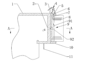
图1为本发明实施例一的永磁直驱风力发电机的定子结构示意图;1 is a schematic structural view of a stator of a permanent magnet direct drive wind power generator according to Embodiment 1 of the present invention;
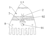
图2为图1中沿A-A向的截面示意图;Figure 2 is a schematic cross-sectional view taken along line A-A of Figure 1;
图3为本发明实施例一的永磁直驱风力发电机的定子铁心内部的气流路径示意图;3 is a schematic diagram of an air flow path inside a stator core of a permanent magnet direct drive wind power generator according to Embodiment 1 of the present invention;
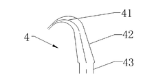
图4为本发明实施例一的设置在永磁直驱风力发电机内的渐缩喷管的结构示意图;4 is a schematic structural view of a tapered nozzle disposed in a permanent magnet direct drive wind power generator according to Embodiment 1 of the present invention;
图5为本发明实施例一的永磁直驱风力发电机的定子内气流获取路径;5 is a flow path of obtaining airflow in a stator of a permanent magnet direct-drive wind power generator according to Embodiment 1 of the present invention;
图6为本发明实施例一的发电机的定子和转子结合部分的结构示意图;6 is a schematic structural view of a stator and a rotor joint portion of a generator according to Embodiment 1 of the present invention;
图7为本发明实施例二的永磁直驱风力发电机的定子和转子结合部分的结构示意图;7 is a schematic structural view of a stator and a rotor joint portion of a permanent magnet direct drive wind power generator according to a second embodiment of the present invention;
图8为本发明实施例二的永磁直驱风力发电机整体结构示意图;8 is a schematic view showing the overall structure of a permanent magnet direct drive wind power generator according to a second embodiment of the present invention;
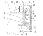
图9为本发明实施例三的永磁直驱风力发电机的定子和转子结合部分的结构示意图。Fig. 9 is a structural schematic view showing a stator-rotor coupling portion of a permanent magnet direct-drive wind power generator according to a third embodiment of the present invention.
附图标号说明:Description of the reference numerals:
1-定子支架;2-第一气孔;3-桨侧围板;4-渐缩喷管;41-弯曲段;42-倾斜段;43-竖直段;5-第二气孔;6-桨侧齿压板;7-冲片固定键;8-定子铁心;9-气流通道;91-轴向通道;92-径向通道;10-塔侧齿压板;11-塔侧围板;12-气源系统;13-母管;14-支管;15-转子支架;16-转子密封环;17-绕组;18-磁极;19-转子端盖;20-端盖密封环;21-第三气孔;22-塔侧密封件。1-stator bracket; 2-first air hole; 3-blade side wall; 4-throwing nozzle; 41-bend section; 42-sloping section; 43-vertical section; 5-second air hole; Side tooth pressure plate; 7-punching plate fixing key; 8- stator core; 9-air flow passage; 91-axial passage; 92-radial passage; 10-tower side pressure plate; 11-tower side coaming; Source system; 13-mother tube; 14-branch tube; 15-rotor bracket; 16-rotor seal ring; 17-winding; 18-pole; 19-rotor end cap; 20-end cap seal ring; 21-third air hole; 22-Tower side seal.
具体实施方式detailed description
下面结合附图对本发明的实施例进行详细描述。The embodiments of the present invention are described in detail below with reference to the accompanying drawings.
本发明实施例的技术原理是利用永磁直驱风力发电机定子铁心内的气流通道将机组内部气源引入到定子铁心的轴向端面上,从而利用该气流在风机的定子和转子组合后形成的内部空间中构建微正压环境,使用微正压气流来抵御外界恶劣气流(气、液、固多相流,其中有空气、水蒸气、雨、雪、盐雾、沙尘、絮状物等)的入侵。本发明实施例所说
的微正压是内部气流或者环境的压力大于外界环境,在程度上能够使外界的气流无法进入电机内部即可。其中,上述的恶劣气流主要是指雨水气液两相流或风雪气固两相流,当然极端情况下也存在气、液、固多相流,例如有空气、水蒸气、雨、雪、盐雾、沙尘、絮状物等。这些恶劣气流主要出现于雨或雪等恶劣的天气状况下,因此,本发明实施例的装置主要是为了抵御这些恶劣气流而设计的,而在正常干燥的天气下,可以不使用本发明实施例的装置,而让干燥气流进入风力发电机中,用于对风机进行干燥、冷却。The technical principle of the embodiment of the present invention is to introduce the internal air source of the unit into the axial end surface of the stator core by using the air flow passage in the stator core of the permanent magnet direct drive wind power generator, so that the air flow is formed after the stator and the rotor of the fan are combined. Construct a micro-positive pressure environment in the internal space, using micro-positive pressure airflow to withstand the harsh external airflow (gas, liquid, solid multiphase flow, including air, water vapor, rain, snow, salt spray, sand dust, floc Etc.). According to an embodiment of the present invention
The micro-positive pressure is that the internal airflow or the ambient pressure is greater than the external environment, so that the external airflow cannot enter the motor. Among them, the above-mentioned severe airflow mainly refers to rainwater gas-liquid two-phase flow or wind-snow gas-solid two-phase flow. Of course, there are also gas, liquid and solid multiphase flows in extreme cases, such as air, water vapor, rain, snow, Salt spray, sand dust, floc, etc. These severe airflows mainly occur in severe weather conditions such as rain or snow. Therefore, the apparatus of the embodiment of the present invention is mainly designed to withstand these severe airflows, and in normal dry weather, the embodiment of the present invention may not be used. The device allows the dry gas stream to enter the wind turbine for drying and cooling the fan.
实施例一 Embodiment 1
如图1所示,其为本发明实施例一的永磁直驱风力发电机的定子结构示意图。为了便于描述可以将图1中的上方定义为桨侧(在风机工作的过程中,桨侧一般会面对上风侧),将下方定义为塔侧(在风机工作的过程中,塔侧一般会面对下风侧),水平方向定义为径向(以整个风机为中心而言的径向),竖直方向定义为轴向(沿着风力发电机的转轴的方向)。此外,定子支架的外周壁是指与定子铁心或者固定定子铁心的冲片固定键相接或者相邻的侧壁,即定子支架的最外侧的部分。FIG. 1 is a schematic structural view of a stator of a permanent magnet direct drive wind power generator according to Embodiment 1 of the present invention. For the convenience of description, the upper part in Fig. 1 can be defined as the paddle side (the blade side generally faces the upwind side during the operation of the fan), and the lower side is defined as the tower side (in the process of the fan operation, the tower side generally Facing the downwind side), the horizontal direction is defined as the radial direction (the radial direction centered on the entire fan), and the vertical direction is defined as the axial direction (the direction along the axis of the wind turbine). Further, the outer peripheral wall of the stator holder refers to a side wall that is in contact with or adjacent to the stator core or the fixed fixing key of the stator core, that is, the outermost portion of the stator holder.
本实施例的永磁直驱风力发电机的定子包括定子支架1、设置在定子支架1外周壁的定子铁心8以及桨侧齿压板6,桨侧齿压板6设置在定子铁心8的桨侧轴向端面上。定子支架为圆筒状,因此在定子支架1的外周壁上可以开有至少一个第一气孔2,在桨侧齿压板6上可以开设有至少一个第二气孔5。定子还可以包括有联通第一气孔2和第二气孔5的至少一个气流通道9,气流通道9可以穿过定子铁心8的内部。The stator of the permanent magnet direct drive wind power generator of the present embodiment includes a stator bracket 1, a stator core 8 disposed on the outer peripheral wall of the stator bracket 1, and a paddle side tooth plate 6, and the paddle side tooth plate 6 is disposed on the paddle shaft of the stator core 8. On the end face. The stator support is cylindrical, so that at least one first air hole 2 can be opened on the outer peripheral wall of the stator support 1, and at least one second air hole 5 can be opened on the paddle side pressure plate 6. The stator may further include at least one air flow passage 9 that communicates the first air hole 2 and the second air hole 5, and the air flow path 9 may pass through the inside of the stator core 8.
其中,第一气孔2和第二气孔5可以为圆形也可以为三角形、椭圆形。此外,气孔也可以为其它形状的导气孔等,总之,只要是能够导通气流即可。优选地,第一气孔2和第二气孔5为圆形气孔,圆形气孔能减少对气流的流动沿程阻力。The first air hole 2 and the second air hole 5 may be circular or triangular or elliptical. Further, the air holes may be air holes of other shapes or the like, and as long as the air flow can be conducted. Preferably, the first air hole 2 and the second air hole 5 are circular air holes, and the circular air holes can reduce the flow resistance to the air flow.
通过该定子结构,能够将定子内部的气流引入到定子铁心的桨侧齿压板6的端面上,从而在风力发电机的桨侧,风力发电机能利用设置于内部的气流源进行自身干燥、冷却或者抵御外界恶劣气流(例如雨或雪等)使之不易进入电机内部,从而能够延长永磁磁极的使用寿命,防止
电机内部器件“绝缘水平降低”,降低电机受恶劣气流(例如雨或雪等)侵蚀的风险以及使得绝缘可靠性能得到保证。With the stator structure, the airflow inside the stator can be introduced to the end surface of the paddle side tooth plate 6 of the stator core, so that on the paddle side of the wind power generator, the wind turbine can dry, cool or use itself by using the air source installed inside. Resist the harsh airflow (such as rain or snow), making it difficult to enter the inside of the motor, thus extending the life of the permanent magnet pole and preventing it
The internal components of the motor "lower insulation level" reduce the risk of the motor being eroded by harsh airflow (such as rain or snow) and ensure insulation reliability.
进一步地,在上述定子结构的基础上,可以在桨侧齿压板6上设置环形的渐缩喷管4,从而控制从定子内部引出的气流,用来实现风机的干燥或者用来抵御外界气流。Further, on the basis of the above-described stator structure, an annular tapered nozzle 4 may be provided on the paddle side tooth pressing plate 6 to control the airflow drawn from the inside of the stator for drying the fan or for resisting external airflow.
下面将对上述定子结构所涉及的气流通道、渐缩喷管、设置在风电机组内部的气源系统以及气流流动路径的可选实施方式进行详细介绍。An alternative embodiment of the air flow passage, the tapered nozzle, the air supply system disposed inside the wind turbine, and the air flow path of the above-described stator structure will be described in detail below.
(1)定子铁心内部的气流通道(1) Airflow passage inside the stator core
定子铁心8内部的气流通道9用于将定子内部的气源12的气流引入到桨侧齿压板6上开设的至少一个第二气孔5处。具体地,如图2所示,其为图1中沿A-A截面截取的气流通道结构示意图,在定子支架1的外周壁上固定有冲片固定键7,定子铁心8(定子铁心由多瓣铁心模块组合而成,每个铁心模块由铁心叠片构成)具有燕尾槽,该燕尾槽套设在冲片固定键7上,从而将定子铁心8固定在定子支架1的外周壁上。第一气孔2可以位于与冲片固定键7接触的定子支架1的外周壁上,气流通道9可以穿过冲片固定键7的气孔与第一气孔2联通。The air flow passage 9 inside the stator core 8 is used to introduce the air flow of the air source 12 inside the stator to the at least one second air hole 5 opened in the paddle side tooth pressure plate 6. Specifically, as shown in FIG. 2 , which is a schematic view of the air flow passage taken along the AA section in FIG. 1 , a punch fixing key 7 is fixed on the outer peripheral wall of the stator bracket 1 , and the stator core 8 (the stator core is composed of a multi-lobed core) The modules are assembled, each core module is composed of a core lamination, and has a dovetail groove which is sleeved on the punch fixing key 7, thereby fixing the stator core 8 to the outer peripheral wall of the stator holder 1. The first air hole 2 may be located on the outer peripheral wall of the stator holder 1 which is in contact with the punch fixing key 7, and the air flow path 9 may communicate with the first air hole 2 through the air hole of the punch fixing key 7.
如图6所示,气流通道9可以包括径向气流通道92和轴向气流通道91,径向气流通道92可以穿过冲片固定键7和定子铁心8的内部,径向气流通道92的一端与第一气孔2连接,另一端与轴向气流通道91连接,轴向气流通道91可以沿轴向穿过定子铁心8的内部与第二气孔5联通。其中,径向气流通道92与轴向气流通道91可以直接连接,也可以经过任意弯曲后再连接,总之,只要能将径向气流通道92和轴向气流通道91连接即可。As shown in FIG. 6, the air flow passage 9 may include a radial air flow passage 92 and an axial air flow passage 91, and the radial air flow passage 92 may pass through the inside of the punch fixing key 7 and the stator core 8, one end of the radial air flow passage 92 The first air hole 2 is connected to the first air hole 2, and the other end is connected to the axial air flow path 91. The axial air flow path 91 can communicate with the second air hole 5 through the inside of the stator core 8 in the axial direction. The radial air flow passage 92 and the axial air flow passage 91 may be directly connected or may be connected after being bent anyway. In short, the radial air flow passage 92 and the axial air flow passage 91 may be connected.
此外,第一气孔2、第二气孔5以及气流通道9可以为多个且数量相等,沿着圆周均等设置。其中,多个第一气孔2、第二气孔5以及气流通道9对应联通,形成多条独立的从定子支架1的内壁到桨侧齿压板6的气流通路。优选地,在定子铁心8的内部桨侧齿压板6的下方,径向气流通道92在定子铁心8内部90度转向进入轴向气流通道91,轴向气流通道91平行于电机定子轴向。如图3所示,其为本发明实施例一的永磁直驱风力发电机的定子铁心内部的气流路径示意图,其中,径
向气流通道与轴向气流通道一一对应,图中仅示出了轴向气流通道,本发明实施例具有若干个气流通道,优选地,如图3所示,共设置有48个气流通道,它们的长度(L1、L2……L48)/内径(d1、d2……d48)/绝对粗糙度(ε1、ε2……ε48)优选为相同,周向间隔也是一致的。Further, the first air hole 2, the second air hole 5, and the air flow path 9 may be plural and equal in number, and are equally disposed along the circumference. The plurality of first air holes 2, the second air holes 5 and the air flow channel 9 are correspondingly connected to each other to form a plurality of independent air flow paths from the inner wall of the stator support 1 to the paddle side pressure plate 6. Preferably, below the inner paddle side pressure plate 6 of the stator core 8, the radial air flow passage 92 is turned 90 degrees inside the stator core 8 into the axial air flow passage 91, which is parallel to the stator axial direction of the motor. As shown in FIG. 3, it is a schematic diagram of an airflow path inside a stator core of a permanent magnet direct-drive wind power generator according to Embodiment 1 of the present invention, wherein the radial airflow passages are in one-to-one correspondence with the axial airflow passages, and only the figure is shown in the figure. The axial air flow passage, the embodiment of the present invention has a plurality of air flow passages. Preferably, as shown in FIG. 3, a total of 48 air flow passages are provided, the lengths thereof (L 1 , L 2 ... L 48 ) / inner diameter ( d 1 , d 2 ... d 48 ) / absolute roughness (ε 1 , ε 2 ... ε 48 ) are preferably the same, and the circumferential intervals are also uniform.
(2)渐缩喷管(2) tapered nozzle
渐缩喷管4的出口可以正对定子与转子之间的间隙,渐缩喷管4可以将气流加速后喷出,在定子与转子之间的间隙处形成微正压气流去主动抵御雨雪天气时段雨或雪“气液两相流”或“气固两相流”的侵入。具体地,如图4所示,其为本发明实施例一的永磁直驱风力发电机的渐缩喷管的结构示意图;在桨侧齿压板6上可以设置有环形的渐缩喷管4(即整体上沿着定子的圆周方向设置),第二气孔5与渐缩喷管4的环形入口联通,可以将定子铁心8内部的气流通道9中的气体引至渐缩喷管4中。The outlet of the tapered nozzle 4 can face the gap between the stator and the rotor. The tapered nozzle 4 can accelerate the airflow and form a micro-positive pressure airflow at the gap between the stator and the rotor to actively resist the rain and snow. Intrusion of “gas-liquid two-phase flow” or “gas-solid two-phase flow” during rain or snow during weather. Specifically, as shown in FIG. 4, it is a schematic structural view of a tapered nozzle of a permanent magnet direct drive wind power generator according to Embodiment 1 of the present invention; an annular tapered nozzle 4 may be disposed on the paddle side tooth pressing plate 6 (i.e., disposed along the circumferential direction of the stator as a whole), the second air hole 5 communicates with the annular inlet of the tapered nozzle 4, and the gas in the air flow passage 9 inside the stator core 8 can be introduced into the tapered nozzle 4.
此外,在风力发电机的上风侧(也称为桨侧,即图6的上侧),定子可以包括桨侧围板3,转子可以包括转子密封环16,在将定子与转子组合安装后,渐缩喷管4的环形出口可以正对着桨侧围板3和转子密封环16形成的环形缝隙。用于封堵桨侧围板3和转子密封环16之间形成的环形缝隙。可选地,由于桨侧围板3为圆环状,因此渐缩喷管4可以制成一体式圆环状喷管,紧密地环扣在桨侧围板3的至少一个第二气孔5处,使得渐缩喷管4与第二气孔5无缝连接,进而使得各个第二气孔5流出的气体充分汇流并使气流的压力均一化,在渐缩喷管4的出口处形成均等的压力。Furthermore, on the windward side of the wind power generator (also referred to as the paddle side, ie the upper side of Figure 6), the stator may comprise a paddle side panel 3, and the rotor may comprise a rotor seal ring 16, after the stator and rotor are combined and mounted, The annular outlet of the tapered nozzle 4 can face the annular gap formed by the paddle shroud 3 and the rotor seal ring 16. It is used to seal the annular gap formed between the paddle side panel 3 and the rotor seal ring 16. Alternatively, since the paddle side panel 3 is annular, the tapered nozzle 4 can be formed as a one-piece annular nozzle that is tightly buckled at at least one second air hole 5 of the paddle side panel 3 The tapered nozzle 4 is seamlessly connected to the second air hole 5, so that the gas flowing out of each of the second air holes 5 is sufficiently converged and the pressure of the air flow is uniformized, and an equal pressure is formed at the exit of the tapered nozzle 4.
在设计渐缩喷管的过程中,使用流体力学中实际流体总流的伯努利方程(能量方程),来分析上风向空气流携带雨水(或雪)撞击风力发电机受阻后,在穿越定子桨侧围板3与转子密封环16(围板)之间环状间隙时,雨水气液两相流或风雪气固两相流(简称外部恶劣气流)在发电机上风向环状间隙前后产生的压力和流速的变化,从而获得外部恶劣气流进入环形缝隙后的压力和流速。然后,利用流体力学的平衡状态而计算此处气压密封射流元件——环形渐缩喷管出口气流的压力和流速。
In the process of designing the tapered nozzle, the Bernoulli equation (energy equation) of the actual fluid flow in the fluid mechanics is used to analyze the upwind air flow carrying rainwater (or snow) after the wind turbine is blocked, after passing through the stator. When the annular gap between the paddle side wall 3 and the rotor seal ring 16 (the coaming plate) is closed, the rainwater gas-liquid two-phase flow or the wind-air gas-solid two-phase flow (referred to as the external harsh air flow) is generated before and after the windward of the generator to the annular gap. The pressure and flow rate change to obtain the pressure and flow rate of the external harsh airflow into the annular gap. Then, using the equilibrium state of hydrodynamics, the pressure and flow rate of the airflow sealing jet element, the annular tapered nozzle outlet flow, are calculated here.
一般来说,环形的渐缩喷管4的出口气流的压力和流速只需要略高于上述的外部恶劣气流进入环形缝隙的压力和流速即可。较为优选地,是环形的渐缩喷管4的出口气流的压力和流速高于外部恶劣气流的压力和流速的3%-5%左右。在确定了环形的渐缩喷管4的出口气流的压力和流速后,由于环形的渐缩喷管4的出口的面积是一定的,因此,可以求得渐缩喷管4的出口所需的气流流量,根据流体流动的连续性原理,用于供给气源的空气压缩机的出口气流流量应该与渐缩喷管4的出口所需的气流流量相等,从而确定了空气压缩机的出口气流流量。In general, the pressure and flow rate of the outlet gas stream of the annular tapered nozzle 4 need only be slightly higher than the pressure and flow rate of the external harsh gas stream entering the annular gap. More preferably, the pressure and flow rate of the outlet gas flow of the annular tapered nozzle 4 is higher than about 3% to 5% of the pressure and flow rate of the external harsh gas flow. After determining the pressure and flow rate of the outlet flow of the annular tapered nozzle 4, since the area of the outlet of the annular tapered nozzle 4 is constant, the desired outlet of the tapered nozzle 4 can be obtained. Air flow rate, according to the principle of continuity of fluid flow, the outlet air flow rate of the air compressor for supplying the air source should be equal to the air flow rate required for the outlet of the tapered nozzle 4, thereby determining the outlet flow rate of the air compressor .
此外,根据压力平衡的原理,用于供给气源的空气压缩机的出口气流的压力应该与环形的渐缩喷管4的出口气流的所需的压力再加上从气源到喷管出口各个环节总的压力降落之和相同,其中,压力降落包括沿程阻力和局部阻力。如上面所述,为了能够抵御外界恶劣气流,在渐缩喷管4的出口处压力需要略高于上述的外部恶劣气流进入环形缝隙的压力,在确定了渐缩喷管4的出口处压力后,再加上从气源到喷管出口各个环节总的压力降落(这个可以根据气流传输通道以及渐缩喷管的结构通过理论计算或者测量而获得)后,就可以确定空气压缩机的出口气流的压力。Further, according to the principle of pressure balance, the pressure of the outlet airflow of the air compressor for supplying the air source should be the same as the required pressure of the outlet airflow of the annular tapered nozzle 4, plus each from the gas source to the nozzle outlet. The sum of the total pressure drop of the link is the same, wherein the pressure drop includes the resistance along the path and the local resistance. As described above, in order to be able to withstand the harsh external airflow, the pressure at the outlet of the tapered nozzle 4 needs to be slightly higher than the pressure of the external harsh airflow entering the annular gap, after determining the pressure at the outlet of the tapered nozzle 4 And, after the total pressure drop from the gas source to the nozzle outlet (this can be obtained by theoretical calculation or measurement according to the structure of the gas flow passage and the tapered nozzle), the outlet flow of the air compressor can be determined. pressure.
由此可见,通过上述理论计算以及实际测量,能够确定出空气压缩机的出口气流的压力和流量。It can be seen from the above theoretical calculations and actual measurements that the pressure and flow rate of the outlet flow of the air compressor can be determined.
进一步地,渐缩喷管4的截面可以呈镰刀形,可以包括依次联通的竖直段43、倾斜段42以及弯曲段41,竖直段43与第二气孔5联通,竖直段43的径向宽度一致且大于或等于第二气孔5的径向宽度,倾斜段42整体上向定子中心方向倾斜,弯曲段41整体上呈圆弧状,其末端形成渐缩喷管4的出口,从倾斜段42到弯曲段41的末端,径向宽度逐渐缩小。气流流经渐缩喷管4能够将气流的压力能转化为气流的动能。Further, the cross section of the tapered nozzle 4 may be in the shape of a sickle, and may include a vertical section 43 that is sequentially connected, a sloped section 42 and a curved section 41. The vertical section 43 communicates with the second air hole 5, and the diameter of the vertical section 43 The width direction is uniform and greater than or equal to the radial width of the second air hole 5, the inclined portion 42 is entirely inclined toward the center of the stator, and the curved portion 41 is formed in an arc shape as a whole, and the end thereof forms an exit of the tapered nozzle 4 from the inclination. From the end of the segment 42 to the curved portion 41, the radial width is gradually reduced. The flow of gas through the tapered nozzle 4 converts the pressure energy of the gas stream into the kinetic energy of the gas stream.
渐缩喷管4依靠气源(例如空气压缩机)提供的足够压力产生高速气流,并且出口流速、流量可控,以适应桨侧风向气流速度的变化。即:气压密封的压力可以根据需要自动调整,实现“自适应”调节,从而减小作为气源的空气压缩机的耗功,节约能源。The tapered nozzle 4 relies on sufficient pressure provided by a source of gas (e.g., an air compressor) to produce a high velocity gas stream, and the outlet flow rate, flow rate is controllable to accommodate changes in the wind speed of the paddle side. That is: the pressure of the air pressure seal can be automatically adjusted as needed to achieve "adaptive" adjustment, thereby reducing the power consumption of the air compressor as a gas source and saving energy.
在本实施例中,通过将内部气源的气流引入到渐缩喷管内,进而可
以通过渐缩喷管将气流加速后在出孔处喷出,由于渐缩喷管出孔正对定子与转子之间的环状间隙,因此电机内部与外界环境之间形成微正压屏障,能主动抵御雨雪天气时段“气液两相流”或“气固两相流”的侵入,借助电机内蓄积大量干燥空气并被微正压挤出,从而排除了电机外界的潮湿气流,使得绕组表面、永磁磁极表面防护覆层达到了干燥要求,降低了电机受雨水或雪融化产生的潮气侵蚀的风险,提高了绝缘可靠性。In this embodiment, by introducing the airflow of the internal air source into the tapered nozzle, the
The airflow is accelerated through the tapered nozzle and sprayed out at the outlet hole. Since the tapered nozzle outlet faces the annular gap between the stator and the rotor, a micro-positive pressure barrier is formed between the interior of the motor and the external environment. It can actively resist the intrusion of “gas-liquid two-phase flow” or “gas-solid two-phase flow” during rain and snow weather, and accumulates a large amount of dry air in the motor and is extruded by micro-positive pressure, thereby eliminating the humid air flow outside the motor, thus making it possible to eliminate the humid air flow outside the motor. The winding surface and the permanent magnetic pole surface protective coating meet the drying requirements, which reduces the risk of moisture erosion caused by rain or snow melting, and improves the insulation reliability.
(3)风电机组内部的气源系统(3) Air source system inside the wind turbine
风电机组内部的气源系统12(具体地,气源系统12可以设置在定子支架之间或者在机舱空间内)中的气源可以取自机舱内的气压发生装置。气源系统12在雨、雪天气时段可以抵御风雨“气液两相流”和风雪“气固两相流”的侵入;气源系统12在需要干燥电机内部的时间段工作,使得在充分干燥发电机定子绝缘和转子磁极防护层的同时减少了气源的能耗。设置在定子中的气流通道9通过第一气孔2与气源系统12连接,将风电机组内部的气源引至气流通道9中。气源系统12可以包括产生预定压力气流的气源发生装置和可以对气流进行净化以及干燥处理的气源处理装置。The air source in the air supply system 12 inside the wind turbine (specifically, the air source system 12 may be disposed between the stator supports or in the cabin space) may be taken from a pneumatic generating device in the nacelle. The gas source system 12 can withstand the intrusion of wind and rain "gas-liquid two-phase flow" and wind and snow "gas-solid two-phase flow" during rain and snow weather; the gas source system 12 works during the time period required to dry the motor, so that it is sufficient Drying the generator stator insulation and the rotor pole protection layer reduces the energy consumption of the air source. The air flow passage 9 provided in the stator is connected to the air supply system 12 through the first air hole 2, and the air source inside the wind turbine is led into the air flow passage 9. The gas source system 12 may include a gas source generating device that generates a predetermined pressure gas stream and a gas source processing device that can purify and dry the gas stream.
气源发生装置可以为空气压缩机,空气压缩机(或压气机)是气压发生装置,它是提高空气的压力或输送空气的机器,也是将原动机供给的机械能转化成空气压力能的一种转换装置。在空气压缩机工作过程中,处于压缩机气缸中的空气被迅速压缩,气体被迅速压缩的过程是一个放热过程,必然引起压缩机气缸的温度升高,因此,一般需进行冷却。在多级压缩的空气压缩机最后一级排气温度可达140—170℃,在这样高的温度下,压缩空气中常混有一定的气态油和水蒸气,需要设置冷却器冷却压缩空气,以初步离析压缩空气中所含的油分和水分,防止油分和水分随压缩空气进入风力发电机定子铁心流道。因此,气源处理装置还可以包括空气过滤器、冷却器、油水分离器以及干燥器。其中,空气过滤器用作过滤进入空气压缩机气缸之前的气体(即过滤机舱内空气中所含的灰尘和其它杂质),用于防止空气中的灰尘、固体杂质等进入空气压缩机后,导致空气压缩机气缸中相对运动部件的摩擦和磨损。The gas source generating device may be an air compressor, and the air compressor (or compressor) is a gas pressure generating device, which is a machine for increasing the pressure of the air or conveying the air, and is also a kind of converting the mechanical energy supplied by the prime mover into the air pressure energy. Conversion device. During the operation of the air compressor, the air in the cylinder of the compressor is rapidly compressed, and the process of rapidly compressing the gas is an exothermic process, which inevitably causes the temperature of the cylinder of the compressor to rise, and therefore, cooling is generally required. In the final stage of multi-stage compression air compressor, the exhaust temperature can reach 140-170 °C. At such high temperature, compressed air is often mixed with certain gaseous oil and water vapor. It is necessary to set a cooler to cool the compressed air. Initially isolates the oil and moisture contained in the compressed air to prevent oil and moisture from entering the wind turbine stator core flow path with compressed air. Therefore, the gas source treatment device may further include an air filter, a cooler, a water separator, and a dryer. Among them, the air filter is used to filter the gas before entering the air compressor cylinder (ie, the dust and other impurities contained in the air in the filter cabin), and is used to prevent dust, solid impurities, etc. in the air from entering the air compressor, resulting in air. Friction and wear of relatively moving parts in the compressor cylinder.
此外,油水分离器(气液分离器)用作进一步分离压缩空气中所含
有的油分和水分,使压缩后的空气得到初步的净化处理,用于消除油分和水分对电机定子支架及其铁心内流道、发电机内部的污染、腐蚀。In addition, a water separator (gas-liquid separator) is used for further separation of compressed air
Some oil and moisture make the compressed air get preliminary purification treatment, which is used to eliminate oil and moisture pollution and corrosion on the motor stator bracket and its internal flow passage and generator.
另外,压缩空气经冷却器和油水分离器后,仍然含有一定的水分,其含量的多少取决于空气的温度、压力和相对湿度的大小。电机内需要的是干燥空气,因此需要设置空气干燥装置,即干燥器。In addition, after the compressed air passes through the cooler and the water separator, it still contains a certain amount of water, and its content depends on the temperature, pressure and relative humidity of the air. Dry air is required in the motor, so an air drying device, that is, a dryer, is required.
进一步地,如图5所示,其为本发明实施例一的永磁直驱风力发电机的定子内气流获取路径,气源系统12可以通过母管13和支管14与第一气孔2连接,可以从母管13上引出与第一气孔2数量相同的支管14,支管14对应连接在第一气孔2上。母管13优选为圆环形,也可以是分段的圆环分段,从而能够减小对气流的流动造成的沿程阻力。Further, as shown in FIG. 5, it is a stator airflow acquisition path of the permanent magnet direct drive wind power generator according to the first embodiment of the present invention, and the air source system 12 can be connected to the first air hole 2 through the mother pipe 13 and the branch pipe 14. The branch pipe 14 having the same number as the first air hole 2 can be taken out from the mother pipe 13, and the branch pipe 14 is correspondingly connected to the first air hole 2. The mother tube 13 is preferably circular or segmented, so that the resistance to the flow of the airflow can be reduced.
(4)气流流动路径(4) Airflow path
如图6所示,其为本发明实施例一的发电机的定子和转子结合部分的结构示意图。图中所示的小箭头代表气流的流通路径。具体地,机舱内空气气流经过气源系统12的过滤干燥压缩后送至定子支架1上的第一气孔2,气流由第一气孔2穿过冲片固定键7进入定子铁心8的径向气流通道92,气流沿径向气流通道92转入轴向气流通道91,之后由轴向气流通道91穿过桨侧齿压板6,进入渐缩喷管4中,经渐缩喷管4加速之后由渐缩喷管4出口处喷出,吹向桨侧围板3与转子密封环16之间的环状间隙,从而去封堵环状旋转间隙,阻止雨雪气固两相流或雨水气液两相流的侵入。FIG. 6 is a schematic structural view of a stator and a rotor coupling portion of a generator according to Embodiment 1 of the present invention. The small arrows shown in the figure represent the flow path of the airflow. Specifically, the airflow in the cabin is filtered and dried by the air source system 12, and then sent to the first air hole 2 on the stator support 1, and the airflow enters the radial airflow of the stator core 8 through the first air hole 2 through the punch fixing key 7. In the passage 92, the airflow is transferred to the axial airflow passage 91 along the radial airflow passage 92, and then passes through the axial airflow passage 91 through the paddle side tooth pressure plate 6, into the tapered nozzle 4, and is accelerated by the tapered nozzle 4 The outlet of the tapered nozzle 4 is sprayed out, and is blown to the annular gap between the paddle side wall 3 and the rotor seal ring 16, thereby blocking the annular rotating gap, preventing rain and snow gas-solid two-phase flow or rain water and liquid. The intrusion of two-phase flow.
具体来说,在风机的工作过程中,桨侧一般是正对上风向,上风向来流撞击发电机定子支架会发生反弹、溅射,再与转子密封环撞击后反射、蓄积,引起气流压力恢复性升高(相比来流时),这些气流将会向桨侧围板3与转子密封环16之间的环状气隙内入侵。本发明实施例的渐缩喷管4所喷出的气流正是用来封堵上述气流的入侵。渐缩喷管4所喷出的气流在封堵外界的入侵气流后,一部分会从桨侧围板3与转子密封环16之间的环状气隙中喷出(这个视气流的压力的大小,也可以不喷出,只要能够起到封堵作用即可),另一部分或者全部气流会撞击转子密封环16,撞击后的反弹气流进入定转子之间的气隙,沿轴向汇集在定子端部机舱侧(即塔侧齿压板10与转子端盖19之间),最后经
端盖密封环20与塔侧围板11之间的环状间隙排入大气环境中,这些在电机内部反弹的部分气流还可以对绕组17和磁极18进行干燥。以上介绍了本实施例的永磁直驱风力发电机的定子的结构示例。在此基础上,在本实施例一还提供了一种永磁直驱风力发电机,其包括转子以及如本实施例提供的定子。此外,本实施例一还提供了一种永磁直驱风力发电机系统,其包括如上述风力发电机以及设置在风电机组内部的气源系统12,气源系统12可以与第一气孔2连接。其中,作为可选的实施方式,气源系统12以及与气源系统12相关联的部件也在前面进行说明,在此不再赘述。Specifically, during the operation of the fan, the paddle side is generally facing upwind, and the upwind flow impinges on the generator stator bracket to rebound and sputter, and then collides with the rotor seal ring to reflect and accumulate, causing airflow pressure recovery. This increase in airflow (compared to the incoming flow) will invade into the annular air gap between the paddle shroud 3 and the rotor seal ring 16. The airflow ejected by the tapered nozzle 4 of the embodiment of the present invention is used to block the intrusion of the above airflow. After the airflow ejected from the tapered nozzle 4 blocks the invading airflow from the outside, a part of it is ejected from the annular air gap between the paddle side wall 3 and the rotor seal ring 16 (the pressure of the apparent airflow) It is also possible not to eject, as long as it can function as a plugging.) Another or all of the airflow will strike the rotor seal ring 16, and the rebounding airflow after the impact enters the air gap between the stator and rotor, and is collected in the stator along the axial direction. The end of the nacelle side (ie between the tower side tooth pressure plate 10 and the rotor end cover 19), and finally
The annular gap between the end cap seal ring 20 and the tower side shroud 11 is vented to the atmosphere, and some of the airflow that bounces inside the motor can also dry the windings 17 and the poles 18. The structural example of the stator of the permanent magnet direct drive wind power generator of the present embodiment has been described above. On this basis, in the first embodiment, a permanent magnet direct drive wind power generator is further provided, which comprises a rotor and a stator as provided in this embodiment. In addition, the first embodiment further provides a permanent magnet direct drive wind power generator system, which includes the wind power generator and the air source system 12 disposed inside the wind turbine, and the air source system 12 can be connected to the first air hole 2 . Wherein, as an alternative embodiment, the air source system 12 and the components associated with the air source system 12 are also described above, and are not described herein again.
实施例二 Embodiment 2
本实施例涉及的定子、永磁直驱风力发电机的具体结构如图7和图8所示,图7为本发明实施例二的永磁直驱风力发电机的定子和转子结合部分的结构示意图,图8为本发明实施例二的永磁直驱风力发电机整体结构示意图。为了便于描述可以将图中的右方定义为桨侧,将左方定义为塔侧,竖直方向定义为径向(以整个风机为中心而言的径向),水平方向定义为轴向(沿着风力发电机的转轴的方向)。图中所示的小箭头代表气流的流通路径。下面将着重说明与实施例一不同之处,未提及的部分的结构可参照实施例一的描述。The specific structure of the stator and the permanent magnet direct drive wind power generator according to the embodiment is shown in FIG. 7 and FIG. 8. FIG. 7 is a structural diagram of the stator and rotor joint portion of the permanent magnet direct drive wind power generator according to the second embodiment of the present invention. FIG. 8 is a schematic view showing the overall structure of a permanent magnet direct drive wind power generator according to a second embodiment of the present invention. For convenience of description, the right side of the figure may be defined as the paddle side, the left side is defined as the tower side, the vertical direction is defined as the radial direction (the radial direction centered on the entire fan), and the horizontal direction is defined as the axial direction (the horizontal direction is defined as the axial direction (the radial direction is centered on the entire fan) Along the direction of the shaft of the wind turbine). The small arrows shown in the figure represent the flow path of the airflow. The difference from the first embodiment will be mainly described below, and the structure of the unmentioned portion can be referred to the description of the first embodiment.
本实施例的定子包括定子支架1、设置在定子支架1外周壁的定子铁心8、桨侧齿压板6以及塔侧齿压板10,桨侧齿压板6设置在定子铁心8的桨侧轴向端面上,塔侧齿压板10设置在定子铁心8的塔侧轴向端面上。在定子支架1的外周壁上开有至少一个第一气孔2,在桨侧齿压板6上开设有至少一个第二气孔5,在塔侧齿压板10上开设有至少一个第三气孔21。定子还包括将第一气孔2与第二气孔5和第三气孔21联通的至少一个气流通道9,气流通道9穿过定子铁心的内部。The stator of the present embodiment includes a stator holder 1, a stator core 8 provided on the outer peripheral wall of the stator holder 1, a paddle side tooth plate 6 and a tower side tooth plate 10, and the paddle side tooth plate 6 is disposed on the paddle side axial end surface of the stator core 8. Upper, the tower side tooth pressing plate 10 is disposed on the tower side axial end surface of the stator core 8. At least one first air hole 2 is opened in the outer peripheral wall of the stator holder 1, and at least one second air hole 5 is opened in the paddle side pressure plate 6, and at least one third air hole 21 is opened in the tower side tooth pressing plate 10. The stator further includes at least one air flow passage 9 that communicates the first air hole 2 with the second air hole 5 and the third air hole 21, and the air flow path 9 passes through the inside of the stator core.
其中,第三气孔21与第一气孔2和第二气孔5类似,可以为圆形也可以为三角形、椭圆形。此外,第三气孔21气孔也可以为其它形状的导气孔等,总之,只要是能够导通气流即可,优选地,第三气孔21为圆形气孔,圆形气孔能减少对气流流动的沿程阻力。The third air hole 21 is similar to the first air hole 2 and the second air hole 5, and may be circular or triangular or elliptical. In addition, the third air hole 21 air hole may also be other shapes of air guiding holes, etc., in general, as long as the air flow can be conducted, preferably, the third air hole 21 is a circular air hole, and the circular air hole can reduce the flow of the air flow. Resistance.
通过该定子结构,能够将定子内部的气流引入到定子铁心的桨侧齿
压板6和塔侧齿压板10的端面上,从而在风力发电机的桨侧和塔侧,风力发电机都能利用设置于内部的气流源进行自身干燥、冷却或者抵御外界恶劣气流使之不易进入电机内部,从而能够延长永磁磁极的使用寿命,防止电机内部器件“绝缘水平降低”,降低电机受恶劣气流(例如雨或雪等)侵蚀的风险以及使得绝缘可靠性能得到保证。Through the stator structure, the airflow inside the stator can be introduced to the paddle teeth of the stator core
The end plate of the pressure plate 6 and the tower side tooth pressure plate 10, so that on the paddle side and the tower side of the wind power generator, the wind power generator can use the air source source disposed inside to dry, cool or resist the bad air flow to make it difficult to enter. The inside of the motor can extend the service life of the permanent magnet pole, prevent the internal insulation of the motor from “lower insulation level”, reduce the risk of the motor being eroded by harsh airflow (such as rain or snow) and ensure the insulation reliability.
进一步地,在上述定子结构的基础上,可以在桨侧齿压板6和塔侧齿压板10上设置环形的渐缩喷管4,从而控制从定子内部引出的气流,用来实现风机的干燥、冷却或者用来抵御外界恶劣气流。Further, on the basis of the above-mentioned stator structure, an annular tapered nozzle 4 may be disposed on the paddle side tooth pressing plate 6 and the tower side tooth pressing plate 10, thereby controlling the airflow drawn from the inside of the stator for drying the fan, Cooled or used to withstand harsh outside airflow.
下面将对上述定子结构中的气流通道、渐缩喷管以及设置在风电机组内部的气源系统以及风机中的气流流动路径的可选实施方式进行详细介绍。An alternative embodiment of the airflow passage, the tapered nozzle, and the air supply system disposed inside the wind turbine and the airflow flow path in the wind turbine will be described in detail below.
(1)定子铁心内部的气流通道(1) Airflow passage inside the stator core
定子铁心8内部的气流通道9用于将定子内部的气源引入到桨侧齿压板6上开设的至少一个第二气孔5以及塔侧齿压板10上开设的至少一个第三气孔21处。同样可以参照图2,在定子支架1的外周壁上固定有冲片固定键7,定子铁心8具有燕尾槽,该燕尾槽套设在冲片固定键7上,从而将定子铁心8固定在定子支架1的外周壁上。第一气孔2可以位于与冲片固定键7接触的定子支架1的外周壁上,冲片固定键7上可以设置有气孔,气流通道9可以穿过冲片固定键7的气孔与第一气孔2联通。The air flow passage 9 inside the stator core 8 is used to introduce a gas source inside the stator into at least one second air hole 5 opened in the paddle side tooth pressure plate 6 and at least one third air hole 21 opened in the tower side tooth pressure plate 10. 2, a punching plate fixing key 7 is fixed on the outer peripheral wall of the stator holder 1. The stator core 8 has a dovetail groove, and the dovetail groove is sleeved on the punch fixing key 7, thereby fixing the stator core 8 to the stator. On the outer peripheral wall of the stent 1. The first air hole 2 may be located on the outer peripheral wall of the stator holder 1 which is in contact with the punch fixing key 7. The punch fixing key 7 may be provided with air holes, and the air flow passage 9 may pass through the air hole of the punch fixing key 7 and the first air hole. 2 Unicom.
如图7所示,与实施例一一样,气流通道9可以包括径向气流通道92和轴向气流通道91,径向气流通道92可以穿过冲片固定键7和定子铁心8的内部,径向气流通道92的一端与第一气孔2连接,另一端与轴向气流通道91连接,与实施例一不同之处在于,轴向气流通道91可以沿轴向穿过定子铁心8的内部与第二气孔5和第三气孔21联通。As shown in FIG. 7, as in the first embodiment, the air flow passage 9 may include a radial air flow passage 92 and an axial air flow passage 91, and the radial air flow passage 92 may pass through the inside of the punch fixing key 7 and the stator core 8, One end of the radial air flow passage 92 is connected to the first air hole 2, and the other end is connected to the axial air flow passage 91. The first embodiment is different from the first embodiment in that the axial air flow passage 91 can pass through the inside of the stator core 8 in the axial direction. The second air hole 5 and the third air hole 21 are in communication.
此外,第一气孔2、第二气孔5、第三气孔21以及气流通道9可以为多个且数量相等,沿着圆周均等设置,其中,多个第一气孔2、第二气孔5、第三气孔21以及气流通道9对应联通,形成多条独立的从定子支架1的内壁到桨侧齿压板6和塔侧齿压板10的气流通路9。
In addition, the first air hole 2, the second air hole 5, the third air hole 21, and the air flow channel 9 may be plural and equal in number, and are equally disposed along the circumference, wherein the plurality of first air holes 2, the second air holes 5, and the third The air hole 21 and the air flow path 9 are correspondingly connected to each other to form a plurality of independent air flow paths 9 from the inner wall of the stator holder 1 to the paddle side pressure plate 6 and the tower side tooth plate 10.
(2)渐缩喷管(2) tapered nozzle
本实施例也可以设置有与实施例一结构相同的渐缩喷管4,只不过,实施例一的渐缩喷管4设置于电机的一侧,而本实施例中,渐缩喷管4设置于电机的两侧。具体地,在本实施例中,在桨侧齿压板6和塔侧齿压板10上分别设置有环形的渐缩喷管4,第二气孔5和第三气孔21分别与对应一侧渐缩喷管的环形入口联通,即桨侧齿压板6上的第二气孔5与桨侧渐缩喷管4的入口联通,塔侧齿压板10上的第三气孔21与塔侧渐缩喷管4的环形入口联通,从而可以将定子铁心8内部的气流通道9中的气体引至渐缩喷管4中。In this embodiment, the tapered nozzle 4 having the same structure as that of the first embodiment may be provided, but the tapered nozzle 4 of the first embodiment is disposed on one side of the motor, and in the embodiment, the tapered nozzle 4 is provided. Set on both sides of the motor. Specifically, in the present embodiment, an annular tapered nozzle 4 is disposed on the paddle side tooth pressing plate 6 and the tower side tooth pressing plate 10, respectively, and the second air hole 5 and the third air hole 21 are respectively tapered with the corresponding side. The annular inlet of the tube is connected, that is, the second air hole 5 on the paddle side pressure plate 6 is in communication with the inlet of the paddle side tapered nozzle 4, the third air hole 21 on the tower side tooth pressure plate 10 and the tower side tapered nozzle 4 The annular inlet is connected so that the gas in the gas flow passage 9 inside the stator core 8 can be introduced into the tapered nozzle 4.
如图7所示,在电机的上风侧(也可以称为桨侧,即图7的右侧),定子可以包括桨侧围板3,转子可以包括转子密封环16,在将定子与转子组合安装后,设置于桨侧齿压板6上的渐缩喷管4的出口可以正对着桨侧围板3和转子密封环16形成的缝隙。用于封堵桨侧围板3和转子密封环16之间形成的环形缝隙。其中,桨侧围板3和转子密封环16均为圆环状。相对应地,在电机的下风侧(也可以称为塔侧,即图7的左侧),定子还可以包括塔侧围板11,转子可以包括转子密封环16和端盖密封环20,在将定子与转子组合安装后,设置在塔侧齿压板10上的渐缩喷管4的出口对着塔侧围板11和端盖密封环20形成的缝隙,用于封堵塔侧围板11和端盖密封环20之间形成的环形缝隙。可选地,由于桨侧围板3和塔侧齿压板10均为圆环状,因此渐缩喷管4可以制成一体式圆环状喷管,紧密地环扣在桨侧围板3和塔侧齿压板10上的至少一个第二气孔5和第三气孔21处,使得渐缩喷管4与第二气孔5无缝连接,进而使得各个第二气孔5流出的气体充分汇流并使气流的压力均一化,在渐缩喷管4的出口处形成均等的压力。As shown in Figure 7, on the windward side of the motor (which may also be referred to as the paddle side, i.e., the right side of Figure 7), the stator may include a paddle side panel 3, and the rotor may include a rotor seal ring 16 in combination with the stator and rotor After installation, the outlet of the tapered nozzle 4 disposed on the paddle side pressure plate 6 may face the gap formed by the paddle side wall 3 and the rotor seal ring 16. It is used to seal the annular gap formed between the paddle side panel 3 and the rotor seal ring 16. Among them, the paddle side panel 3 and the rotor seal ring 16 are both annular. Correspondingly, on the leeward side of the motor (which may also be referred to as the tower side, ie the left side of Figure 7), the stator may further comprise a tower side panel 11 which may comprise a rotor seal ring 16 and an end cap seal ring 20, After the stator and the rotor are assembled in combination, the outlet of the tapered nozzle 4 disposed on the tower side tooth pressure plate 10 faces the slit formed by the tower side wall 11 and the end cap sealing ring 20 for sealing the tower side panel 11 An annular gap formed between the end cap seal ring 20. Alternatively, since both the paddle side panel 3 and the tower side tooth pressure plate 10 are annular, the tapered nozzle 4 can be formed as a one-piece annular nozzle, tightly buckled on the paddle side panel 3 and The at least one second air hole 5 and the third air hole 21 on the tower side tooth pressure plate 10 are such that the tapered nozzle 4 and the second air hole 5 are seamlessly connected, so that the gas flowing out from each of the second air holes 5 is fully converge and the air flow is made. The pressure is uniform and equal pressure is formed at the outlet of the tapered nozzle 4.
与实施例一一样,如图4所示,渐缩喷管4的径向剖面可以呈镰刀形,可以包括依次联通的竖直段43、倾斜段42以及弯曲段41。其中,设置在桨侧齿压板6和塔侧齿压板10上的渐缩喷管4的竖直段43分别与第二气孔5和第三气孔21联通,即桨侧的渐缩喷管4的竖直段43与第二气孔5联通,塔侧的渐缩喷管4的竖直段43与第三气孔21联通。竖直段43的径向宽度一致且大于或等于第二气孔5和第
三气孔21的径向宽度。倾斜段42整体上向定子中心方向倾斜,弯曲段41整体上呈圆弧状,其末端形成渐缩喷管的出口,从倾斜段42到弯曲段41的末端,径向宽度逐渐缩小。As in the first embodiment, as shown in FIG. 4, the radial section of the tapered nozzle 4 may be in the shape of a sickle, and may include a vertical section 43, a sloped section 42, and a curved section 41 which are sequentially connected. Wherein, the vertical sections 43 of the tapered nozzles 4 disposed on the paddle side tooth pressing plate 6 and the tower side tooth pressing plate 10 are in communication with the second air hole 5 and the third air hole 21, respectively, that is, the paddle side tapered nozzle 4 The vertical section 43 communicates with the second air hole 5, and the vertical section 43 of the tapered nozzle 4 on the tower side communicates with the third air hole 21. The vertical width of the vertical section 43 is uniform and greater than or equal to the second air hole 5 and
The radial width of the three air holes 21. The inclined section 42 is entirely inclined toward the center of the stator, and the curved section 41 has an arc shape as a whole, and the end thereof forms an outlet of the tapered nozzle, and the radial width gradually decreases from the inclined section 42 to the end of the curved section 41.
(3)风电机组内部的气源系统(3) Air source system inside the wind turbine
气源系统12的结构及相关部件与实施例一相同。The structure and related components of the air source system 12 are the same as in the first embodiment.
(4)气流流动路径(4) Airflow path
如图7和图8所示,图中所示的小箭头代表气流的流通路径,机舱内空气气流经过气源系统12的过滤干燥压缩后送至定子支架1上的第一气孔2,气流由第一气孔2穿过冲片固定键7进入定子铁心8的径向气流通道92,气流沿径向气流通道92转入轴向气流通道91,之后由轴向气流通道91穿过桨侧齿压板6和塔侧齿压板10,进入两侧的渐缩喷管4中,经渐缩喷管4加速之后由渐缩喷管4出口处喷出,分别吹向桨侧围板3与转子密封环16之间的环状间隙和塔侧围板11和端盖密封环20之间的环状缝隙,从而从风力发电机的两侧去封堵定子和转子之间的环状间隙,阻止雨雪气固两相流或雨水气液两相流的侵入。As shown in FIG. 7 and FIG. 8, the small arrow shown in the figure represents the flow path of the airflow, and the airflow in the cabin is filtered and dried by the air source system 12, and then sent to the first air hole 2 on the stator support 1, and the air flow is The first air hole 2 enters the radial air flow passage 92 of the stator core 8 through the punch fixing key 7, and the air flow is transferred to the axial air flow passage 91 along the radial air flow passage 92, and then the axial air flow passage 91 passes through the paddle side tooth pressure plate. 6 and the tower side tooth pressure plate 10, enters the tapered nozzles 4 on both sides, is accelerated by the tapered nozzle 4, and is ejected from the outlet of the tapered nozzle 4, respectively, to the paddle side wall 3 and the rotor seal ring An annular gap between 16 and an annular gap between the tower side shroud 11 and the end cap seal ring 20, thereby blocking the annular gap between the stator and the rotor from both sides of the wind turbine to prevent rain and snow Intrusion of gas-solid two-phase flow or rainwater gas-liquid two-phase flow.
上述实施例一所形成的气流路径是用来封堵从桨侧围板3与转子密封环16之间的环状气隙入侵的外界恶劣气流(从桨侧入侵的气流),而本实施例的结构所形成的气流路径还能够封堵从盖密封环20与塔侧围板11之间的环状缝隙入侵的外界恶劣气流(从塔侧入侵的气流)。即,本发明实施例的在桨侧和塔侧均设置了环形的渐缩喷管4,从而可以在两侧对外界恶劣气流进行封堵。The air flow path formed in the first embodiment is used to block the external harsh airflow (the airflow invading from the paddle side) invading from the annular air gap between the paddle panel 3 and the rotor seal ring 16, and this embodiment The air flow path formed by the structure can also block the external harsh airflow (the airflow invading from the tower side) intruding from the annular gap between the cover seal ring 20 and the tower side panel 11. That is, in the embodiment of the present invention, an annular tapered nozzle 4 is provided on both the paddle side and the tower side, so that the external bad airflow can be blocked on both sides.
一般情况下,在风机的工作过程中,桨侧一般是正对上风向,在风机的上风侧的外界气流较强,上风向来流撞击发电机定子支架会发生反弹、溅射,再与转子密封环撞击后反射、蓄积,引起气流压力恢复性升高(相比来流时),这些气流将会向桨侧围板3与转子密封环16之间的环状气隙内入侵。Under normal circumstances, during the working process of the fan, the paddle side is generally facing the upwind direction, and the outside airflow on the windward side of the fan is strong, and the upwind flow impinges on the generator stator bracket to rebound, sputter, and then seal with the rotor. After the ring impacts, it reflects and accumulates, causing the airflow pressure to recover (in comparison with the incoming flow), and these airflows will invade into the annular air gap between the paddle side wall 3 and the rotor seal ring 16.
渐缩喷管4所喷出的气流在封堵外界的来自桨侧入侵气流后,一部分会从桨侧围板3与转子密封环16之间的环状气隙中喷出(这个视气流的压力的大小,也可以不喷出,只要能够起到封堵作用即可),另一部分或者全部气流会撞击转子密封环16,撞击后的反弹气流进入定转
子之间的气隙,最后经端盖密封环20与塔侧围板11之间的环状间隙排入大气环境中,这部分在电机内部反弹的气流还可以对干燥绕组17和磁极18进行干燥。The airflow ejected from the tapered nozzle 4 is partially ejected from the annular air gap between the paddle side wall 3 and the rotor seal ring 16 after blocking the outside intrusion flow from the paddle side (this airflow The magnitude of the pressure may not be ejected as long as it can function as a plugging.) Another or all of the airflow will strike the rotor seal ring 16, and the rebound airflow after the impact enters the fixed revolution.
The air gap between the sub-intervals is finally discharged into the atmosphere through the annular gap between the end cap seal ring 20 and the tower side shroud 11, and this part of the airflow rebounding inside the motor can also perform the dry winding 17 and the magnetic pole 18. dry.
在这种情况下,由于塔侧的外界气流相对于桨侧的外界气流弱,因此,设置在塔侧的渐缩喷管4所喷出的气流可以直接从塔侧围板11和端盖密封环20之间的环状缝隙中喷出。In this case, since the outside airflow on the tower side is weak with respect to the outside airflow on the paddle side, the airflow ejected from the tapered nozzle 4 provided on the tower side can be directly sealed from the tower side wall panel 11 and the end cap The annular gap between the rings 20 is ejected.
另一方面,鉴于风场的环境复杂并且风向也可能多变,并且,风机在处于停机状态时,桨侧和塔侧所面对的风向也会发生变化。很多情况下,也会出现塔侧入侵的外界气流较强。在这种情况下就需要设置在塔侧的渐缩喷管4对外界的恶劣气流进行封堵。On the other hand, in view of the complex environment of the wind farm and the change of wind direction, and the wind direction of the wind turbine, the wind direction faced by the paddle side and the tower side also changes. In many cases, there will also be strong external airflow on the tower side. In this case, it is necessary to provide a tapered nozzle 4 disposed on the tower side to block the harsh airflow from the outside.
在这种情况下,塔侧的外界气流较强,而桨侧的外界气流较弱。渐缩喷管4所喷出的气流在封堵外界的来自塔侧入侵气流后,一部分会从塔侧围板11和端盖密封环20之间的环状气隙中喷出(这个视气流的压力的大小,也可以不喷出,只要能够起到封堵作用即可),另一部分或者全部气流会撞击端盖密封环20,撞击后的反弹气流进入定转子之间的气隙,最后经桨侧围板3与转子密封环16之间的环状气隙排入大气环境中,这些在电机内部反弹的部分气流同样可以对绕组17和磁极18进行干燥。In this case, the outside airflow on the tower side is strong, and the outside airflow on the paddle side is weak. The airflow ejected from the tapered nozzle 4 is partially ejected from the annular air gap between the tower side shroud 11 and the end cap sealing ring 20 after blocking the outside intrusion flow from the tower side (this apparent airflow) The magnitude of the pressure may not be ejected as long as it can function as a plugging.) Another or all of the airflow will hit the end cap seal ring 20, and the rebounding airflow after the impact enters the air gap between the stator and rotor. Finally, An annular air gap between the paddle side wall 3 and the rotor seal ring 16 is discharged into the atmosphere, and part of the air current that bounces inside the motor can also dry the winding 17 and the magnetic pole 18.
在本实施例中,由于在塔侧也设置了渐缩喷管4,因此,相比实施例一而言,能够对来自桨侧和塔侧的外界气流都进行封堵,从而更好地保证风机内部不受到外界气流的侵扰。In the present embodiment, since the tapered nozzle 4 is also provided on the tower side, it is possible to block the external airflow from the paddle side and the tower side as compared with the first embodiment, thereby better ensuring The inside of the fan is not invaded by the outside airflow.
此外,在本实施例二还提供了一种永磁直驱风力发电机,可以包括转子以及如本实施例提供的定子,具体结构如图8所示。In addition, in the second embodiment, a permanent magnet direct-drive wind power generator is provided, which may include a rotor and a stator as provided in this embodiment. The specific structure is as shown in FIG. 8.
此外,本实施例二还提供了一种永磁直驱风力发电机系统,可以包括如上述风力发电机以及设置在风电机组内部的气源系统12,气源系统12可以与第一气孔2连接。其中,作为可选的实施方式,气源系统12以及与气源系统12相关联的部件也在前面进行说明,在此不再赘述。In addition, the second embodiment further provides a permanent magnet direct drive wind power generator system, which may include a wind power generator as described above and a gas source system 12 disposed inside the wind turbine, and the air source system 12 may be connected to the first air hole 2. . Wherein, as an alternative embodiment, the air source system 12 and the components associated with the air source system 12 are also described above, and are not described herein again.
实施例三 Embodiment 3
本实施例涉及的定子、永磁直驱风力发电机的具体结构,如图9所示,其为本发明实施例三的永磁直驱风力发电机的定子和转子结合部
分的结构示意图,为了便于描述可以将图中的右方定义为桨侧(在风机工作的过程中,桨侧一般会面对上风侧),将左方定义为塔侧(在风机工作的过程中,桨侧一般会面对下风侧),竖直方向定义为径向(以整个风机为中心而言的径向),水平方向定义为轴向(沿着风力发电机的转轴的方向)。图中所示的小箭头代表气流的流通路径。下面将着重说明与实施例一和实施例二的不同之处,未提及的部分的结构可参照实施例一的描述。The specific structure of the stator and permanent magnet direct drive wind power generator according to the embodiment is shown in FIG. 9 , which is the stator and rotor joint of the permanent magnet direct drive wind power generator according to the third embodiment of the present invention.
For the convenience of description, the right side of the figure can be defined as the paddle side (the blade side generally faces the upwind side during the operation of the fan), and the left side is defined as the tower side (the process of working in the fan) In the middle, the paddle side generally faces the downwind side), the vertical direction is defined as the radial direction (the radial direction centered on the entire fan), and the horizontal direction is defined as the axial direction (the direction along the axis of the wind turbine). The small arrows shown in the figure represent the flow path of the airflow. The differences from the first embodiment and the second embodiment will be mainly described below, and the structure of the unmentioned portion can be referred to the description of the first embodiment.
本实施例的永磁直驱风力发电机的定子包括定子支架1、设置在定子支架1外周壁的定子铁心8以及塔侧齿压板10,塔侧齿压板10设置在定子铁心8的塔侧轴向端面上。在定子支架1的外周壁上可以开有至少一个第一气孔2,在塔侧齿压板10上开设有至少一个第三气孔21。定子还可以包括有联通第一气孔2和第三气孔21的至少一个气流通道9,气流通道9可以穿过定子铁心8的内部。The stator of the permanent magnet direct drive wind power generator of the present embodiment includes a stator bracket 1, a stator core 8 disposed on the outer peripheral wall of the stator bracket 1, and a tower side tooth pressing plate 10, and the tower side tooth pressing plate 10 is disposed on the tower side shaft of the stator core 8. On the end face. At least one first air hole 2 may be opened in the outer peripheral wall of the stator holder 1, and at least one third air hole 21 is opened in the tower side tooth pressure plate 10. The stator may further include at least one air flow passage 9 that communicates the first air hole 2 and the third air hole 21, and the air flow path 9 may pass through the inside of the stator core 8.
通过该定子结构,能够将定子中部的气流引入到定子铁心的塔侧齿压板10的端面上,从而在风力发电机的塔侧,风力发电机能利用设置于内部的气流源进行自身干燥或者抵御外界恶劣气流使之不易进入电机内部,从而能够延长永磁磁极的使用寿命,防止电机内部器件“绝缘水平降低”,降低电机受恶劣气流(例如雨或雪等)侵蚀的风险以及使得绝缘可靠性能得到保证。With the stator structure, the airflow in the middle of the stator can be introduced to the end surface of the tower side tooth pressure plate 10 of the stator core, so that on the tower side of the wind power generator, the wind power generator can dry itself or resist the outside world by using the air source installed inside. The harsh airflow makes it difficult to enter the inside of the motor, which can extend the service life of the permanent magnet pole, prevent the internal insulation of the motor from "insulation level", reduce the risk of the motor being eroded by harsh airflow (such as rain or snow) and enable insulation reliability. Guarantee.
另外,与实施例一和实施例二的不同之处在于,本实施例没有在定子上设置渐缩喷管。In addition, the difference from the first embodiment and the second embodiment is that the present embodiment does not provide a tapered nozzle on the stator.
此外,本实施例还提供了一种永磁直驱风力发电机,可以包括转子以及如本实施例提供的定子。其中,定子可以包括塔侧围板11,转子可以包括端盖密封环20,在塔侧围板11和端盖密封环20之间可以设置有塔侧密封件22,塔侧密封件22可以固定在塔侧围板11或者端盖密封环20的一方上,以动密封的方式密封塔侧围板11和端盖密封环20之间的缝隙。Furthermore, the present embodiment also provides a permanent magnet direct drive wind power generator, which may include a rotor and a stator as provided in this embodiment. Wherein, the stator may include a tower side shroud 11, the rotor may include an end cap seal ring 20, and a tower side seal 22 may be disposed between the tower side shroud 11 and the end cap seal ring 20, and the tower side seal 22 may be fixed On one side of the tower side shroud 11 or the end cap seal ring 20, the gap between the tower side shroud 11 and the end cap seal ring 20 is sealed in a dynamic seal manner.
与上述两个实施例的不同之处在于,本实施例没有利用渐缩喷管来构建微正压的环境,而是完全依靠风机内部的气流流动来构建微正压的环境来抵御外界气流的入侵。
The difference from the above two embodiments is that the present embodiment does not utilize a tapered nozzle to construct a micro-positive pressure environment, but completely relies on the flow of air inside the fan to construct a micro-positive pressure environment to resist external airflow. Invasion.
此外,本实施例还提供了一种永磁直驱风力发电机系统,可以包括如上述风力发电机以及设置在风电机组内部的气源系统12,气源系统12可以与第一气孔2连接。其中,气源系统12的结构和设置与实施例一相同。In addition, the embodiment further provides a permanent magnet direct drive wind power generator system, which may include a wind power generator as described above and a gas source system 12 disposed inside the wind turbine, and the air source system 12 may be connected to the first air hole 2. The structure and arrangement of the air source system 12 are the same as those in the first embodiment.
下面将对上述定子结构中的气流通道、设置在风电机组内部的气源系统以及风机内部的气流流动路径的可选实施方式进行详细介绍。An alternative embodiment of the air flow passage in the stator structure, the air supply system disposed inside the wind turbine, and the air flow flow path inside the fan will be described in detail below.
(1)定子铁心内部的气流通道(1) Airflow passage inside the stator core
如图9所示,与实施例一一样,气流通道9可以包括径向气流通道92和轴向气流通道91,径向气流通道92可以穿过冲片固定键7和定子铁心8的内部,径向气流通道92的一端与第一气孔2连接,另一端与轴向气流通道91连接。与实施例一不同之处在于,轴向气流通道91可以沿轴向穿过定子铁心8的内部与第三气孔21联通。As shown in FIG. 9, as in the first embodiment, the air flow passage 9 may include a radial air flow passage 92 and an axial air flow passage 91, and the radial air flow passage 92 may pass through the inside of the punch fixing key 7 and the stator core 8, One end of the radial air flow passage 92 is connected to the first air hole 2, and the other end is connected to the axial air flow path 91. The difference from the first embodiment is that the axial air flow passage 91 can communicate with the third air hole 21 through the inside of the stator core 8 in the axial direction.
此外,第一气孔2、第三气孔21以及气流通道9可以为多个且数量相等,沿着圆周均等设置,其中,多个第一气孔2、第三气孔21以及气流通道9对应联通,形成多条独立的从定子支架1的内壁到塔侧齿压板10的气流通道9。In addition, the first air hole 2, the third air hole 21, and the air flow channel 9 may be plural and equal in number, and are equally disposed along the circumference, wherein the plurality of first air holes 2, the third air holes 21, and the air flow channel 9 are correspondingly connected to each other to form A plurality of independent air flow passages 9 from the inner wall of the stator holder 1 to the tower side pressure plate 10.
(2)风电机组内部的气源系统(2) Air source system inside the wind turbine
气源系统12的结构及相关部件与实施例一相同。The structure and related components of the air source system 12 are the same as in the first embodiment.
(3)气流流动路径(3) Airflow path
本实施例的微正压环境没有借助渐缩喷管来实现,而是利用塔侧密封件22对气流的封堵来实现的。The micro-negative pressure environment of this embodiment is achieved without the aid of a tapered nozzle, but by the plugging of the gas flow by the tower side seal 22.
如图9所示,图中所示的小箭头代表气流的流通路径。具体地,机舱内空气气流经过气源系统12的过滤干燥压缩后送至定子支架1上的第一气孔2,气流由第一气孔2穿过冲片固定键7进入定子铁心8的径向气流通道92,气流沿径向气流通道92转入轴向气流通道91,机舱内空气气流到达轴向通道91后,由于桨侧封闭,气流便从第三气孔21流出,向发电机下风向端部流去,由于在塔侧围板11和端盖密封环20之间设置了塔侧密封件22,对气流进行了封堵,绝大部分气流又进入定子支架1与转子支架15形成的环状气隙内,在环状气隙内气流经过塔侧绕组17、磁极18、到达桨侧绕组端部,最终聚压挤出桨侧围板3
与转子密封环16之间的环状间隙排入大气环境中。As shown in Fig. 9, the small arrows shown in the figure represent the flow paths of the airflow. Specifically, the airflow in the cabin is filtered and dried by the air source system 12, and then sent to the first air hole 2 on the stator support 1, and the airflow enters the radial airflow of the stator core 8 through the first air hole 2 through the punch fixing key 7. In the passage 92, the airflow is transferred to the axial airflow passage 91 along the radial airflow passage 92. After the airflow in the cabin reaches the axial passage 91, the airflow flows out from the third air hole 21 due to the closed side of the blade, and the wind is directed to the end of the generator. Flowing, since the tower side seal 22 is disposed between the tower side shroud 11 and the end cap seal ring 20, the airflow is blocked, and most of the airflow enters the ring formed by the stator bracket 1 and the rotor bracket 15 again. In the air gap, the airflow in the annular air gap passes through the tower side winding 17, the magnetic pole 18, reaches the end of the paddle winding, and finally the polycondensed extrusion paddle side panel 3
An annular gap with the rotor seal ring 16 is vented to the atmosphere.
这种方案的优点是:由于干燥气流需要经过定子支架1与转子支架15形成的环状气隙,因此,能够对塔侧和桨侧的绕组17和磁极18进行干燥,同时还可以在上风侧形成微正压气流,来抵御外界气流进入电机内部。The advantage of this solution is that since the dry airflow needs to pass through the annular air gap formed by the stator bracket 1 and the rotor bracket 15, the windings 17 and the magnetic poles 18 on the tower side and the paddle side can be dried, and also on the windward side. A micro-positive pressure airflow is formed to prevent external airflow from entering the interior of the motor.
以上所述,仅为本发明的具体实施方式,但本发明的保护范围并不局限于此,任何熟悉本技术领域的技术人员在本发明揭露的技术范围内,可轻易想到变化或替换,都应涵盖在本发明的保护范围之内。因此,本发明的保护范围应以所述权利要求的保护范围为准。
The above is only a specific embodiment of the present invention, but the scope of the present invention is not limited thereto, and any person skilled in the art can easily think of changes or substitutions within the technical scope of the present invention. It should be covered by the scope of the present invention. Therefore, the scope of the invention should be determined by the scope of the appended claims.