WO2016113790A1 - Threaded pipe joint - Google Patents
Threaded pipe joint Download PDFInfo
- Publication number
- WO2016113790A1 WO2016113790A1 PCT/JP2015/005830 JP2015005830W WO2016113790A1 WO 2016113790 A1 WO2016113790 A1 WO 2016113790A1 JP 2015005830 W JP2015005830 W JP 2015005830W WO 2016113790 A1 WO2016113790 A1 WO 2016113790A1
- Authority
- WO
- WIPO (PCT)
- Prior art keywords
- pin member
- nose
- threaded joint
- curve
- pipes
- Prior art date
Links
Images


Classifications
-
- E—FIXED CONSTRUCTIONS
- E21—EARTH DRILLING; MINING
- E21B—EARTH DRILLING, e.g. DEEP DRILLING; OBTAINING OIL, GAS, WATER, SOLUBLE OR MELTABLE MATERIALS OR A SLURRY OF MINERALS FROM WELLS
- E21B17/00—Drilling rods or pipes; Flexible drill strings; Kellies; Drill collars; Sucker rods; Cables; Casings; Tubings
- E21B17/02—Couplings; joints
- E21B17/04—Couplings; joints between rod or the like and bit or between rod and rod or the like
- E21B17/042—Threaded
- E21B17/0426—Threaded with a threaded cylindrical portion, e.g. for percussion rods
-
- F—MECHANICAL ENGINEERING; LIGHTING; HEATING; WEAPONS; BLASTING
- F16—ENGINEERING ELEMENTS AND UNITS; GENERAL MEASURES FOR PRODUCING AND MAINTAINING EFFECTIVE FUNCTIONING OF MACHINES OR INSTALLATIONS; THERMAL INSULATION IN GENERAL
- F16L—PIPES; JOINTS OR FITTINGS FOR PIPES; SUPPORTS FOR PIPES, CABLES OR PROTECTIVE TUBING; MEANS FOR THERMAL INSULATION IN GENERAL
- F16L15/00—Screw-threaded joints; Forms of screw-threads for such joints
- F16L15/04—Screw-threaded joints; Forms of screw-threads for such joints with additional sealings
-
- F—MECHANICAL ENGINEERING; LIGHTING; HEATING; WEAPONS; BLASTING
- F16—ENGINEERING ELEMENTS AND UNITS; GENERAL MEASURES FOR PRODUCING AND MAINTAINING EFFECTIVE FUNCTIONING OF MACHINES OR INSTALLATIONS; THERMAL INSULATION IN GENERAL
- F16L—PIPES; JOINTS OR FITTINGS FOR PIPES; SUPPORTS FOR PIPES, CABLES OR PROTECTIVE TUBING; MEANS FOR THERMAL INSULATION IN GENERAL
- F16L15/00—Screw-threaded joints; Forms of screw-threads for such joints
- F16L15/001—Screw-threaded joints; Forms of screw-threads for such joints with conical threads
- F16L15/004—Screw-threaded joints; Forms of screw-threads for such joints with conical threads with axial sealings having at least one plastically deformable sealing surface
-
- F—MECHANICAL ENGINEERING; LIGHTING; HEATING; WEAPONS; BLASTING
- F16—ENGINEERING ELEMENTS AND UNITS; GENERAL MEASURES FOR PRODUCING AND MAINTAINING EFFECTIVE FUNCTIONING OF MACHINES OR INSTALLATIONS; THERMAL INSULATION IN GENERAL
- F16L—PIPES; JOINTS OR FITTINGS FOR PIPES; SUPPORTS FOR PIPES, CABLES OR PROTECTIVE TUBING; MEANS FOR THERMAL INSULATION IN GENERAL
- F16L15/00—Screw-threaded joints; Forms of screw-threads for such joints
- F16L15/06—Screw-threaded joints; Forms of screw-threads for such joints characterised by the shape of the screw-thread
Definitions
- the present invention relates to a threaded joint for pipes, and in particular, oil well pipes including tubing and casings generally used for exploration and production of oil wells and gas wells, that is, OCTG (oil country tubular goods), riser pipes, line pipes and the like
- the present invention relates to a threaded joint for pipes having an outer diameter of 168.3 mm or less, excellent in sealing performance and compression resistance, suitable for use in connecting steel pipes.
- Threaded joints are widely used for connecting pipes used in oil industry equipment such as oil well pipes.
- API American Petroleum Institute
- a premium joint is a joint in which a pin member and a box member each having a taper screw, a seal portion (specifically, a metal touch seal portion), and a shoulder portion (specifically, a torque shoulder portion) are combined.
- the taper screw is important for firmly fixing the pipe joint.
- the seal portion plays a role of ensuring sealing performance by the metal member contacting the box member and the pin member at this portion.
- the shoulder portion becomes a shoulder surface that serves as a stopper during tightening of the joint.
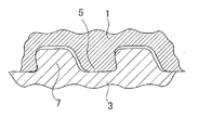
- FIGS. 2 to 4 are schematic explanatory diagrams of premium joints for oil well pipes, which are longitudinal sectional views (axial sectional views) of a threaded joint of a circular pipe.
- the threaded joint includes a pin member 3 and a box member 1 corresponding thereto, and the pin member 3 (pin 3) is provided on the outer surface thereof adjacent to the male screw 7 and on the tip side of the pin 3 adjacent to the male screw 7.
- a no-thread portion called a nose portion 8 (pin nose 8).
- the nose portion 8 has a seal portion 11 on its outer peripheral surface and a torque shoulder portion 12 on its end surface.
- the opposing box member 1 has, on its inner surface, a female screw 5, a seal portion 13, and a portion that can be screwed or contacted with the male screw 7, the seal portion 11, and the shoulder portion 12 of the pin 3, respectively.
- the shoulder portion 14 is provided.
- Patent Documents 1 to 7 can be cited as conventional techniques related to the premium joint.
- Patent Document 1 proposes a threaded joint in which a metal touch seal portion is provided near the screw portion of the pin nose 8 and the nose portion is extended from the seal portion to the shoulder portion in order to increase external pressure resistance.
- the pin nose that is not in contact with the box member is configured to be elongated so as to be discontinuous with the seal portion so that the thickness of the pin nose is not reduced.
- the axial compression resistance is also improved.
- an appendix is formed from the seal portion to the pin nose tip, which also has a portion having a discontinuous shape with the seal portion to ensure radial rigidity and lower axial rigidity. It is described that this appendix is deformed at the time of tightening and the tensile resistance is improved by recovering the appendix when loaded.
- Patent Document 3 discloses an example of a radial seal method having a large pin seal R shape and a small seal taper angle.
- a problem with the radial seal method in which the seal taper angle is thus reduced is that goling is likely to occur during tightening.
- the ease of occurrence of goling is further increased.
- the radius of the toroidal (conical curved rotating surface shape) pin seal surface is specified to be large, so that the seal contact area is enlarged and the contact pressure is reduced. This measure is effective, and can greatly reduce the goling risk of the metal touch seal part.
- the contact pressure is lowered with some slight trouble, and if a minute leak path is formed in the metal touch seal part, the leak does not stop easily.
- the large R it is physically difficult to separate the metal touch seal part from the nose tip. When the length of the metal touch seal part and the pin nose tip is secured to a certain extent, the thickness of the pin nose tip is It leads to becoming too small.
- Patent Document 7 as a means for solving the above-mentioned problems that have not been solved in Patent Documents 1 to 6, the outer peripheral surface of the nose portion of the pin member is formed in a compound R curve shape that is convex outward in an axial sectional view. It proposes making the inner peripheral surface of the box member which opposes a taper shape. Thereby, the effect that it becomes possible to obtain the screw joint for pipes which improved sealability, compression resistance, and also galling resistance is anticipated.
- Patent Document 7 when the technique described in Patent Document 7 is applied to a case where a pipe having an outer diameter of, for example, 168.3 mm or less is used as an element pipe of the pin member, the rigidity of the pin member becomes insufficient, and the external pressure resistance performance is reduced.
- the present inventors have found that there is a case where it decreases, from examination by experiment and calculation.
- the conventional threaded joints still have some problems.
- the above-mentioned compression resistance and bending resistance are obtained when the outer diameter of the raw pipe portion of the pin member, that is, the outer diameter of the remaining length portion excluding the male threaded portion on the tip side is 168.3 mm or less.
- the present invention provides a threaded joint for pipes that has improved sealing performance, compression resistance, and galling resistance, particularly when the outer diameter of the raw pipe portion is 168.3 mm or less. The purpose is to provide.
- a pin member having a male screw portion, a nose portion extending from the male screw portion toward the tube end side, and a shoulder portion provided at the tip of the nose portion;
- a box member having a female screw portion that is screw-coupled to the male screw portion, an inner peripheral surface that faces the outer peripheral surface of the nose portion of the pin member, and a shoulder portion that contacts the shoulder portion of the pin member;
- the outer peripheral surface of the nose portion of the pin member has an outwardly convex curve in the axial sectional view of the pin member, and the convex curve has a radius of curvature R different from the generatrix of the cylindrical portion adjacent to the external thread portion.
- the radius of curvature R of the arc increases as the distance from the male thread portion increases, and the tangent line on the connection point of the arc is the connection partner's arc.
- the inner peripheral surface of the box member is a tapered surface that interferes with the outer peripheral surface of the nose portion of the pin member when coupled with the pin member,
- a threaded joint for pipes characterized in that the outer diameter of the raw pipe portion of the pin member is 168.3 mm or less, and the length of the nose portion is 5 mm or more and less than 20 mm.
- the male screw portion Threaded joint for pipes characterized in that it is a composite R curve in which a plurality of circular arcs having different curvature radii R are sequentially connected to a generatrix of a cylindrical portion adjacent to each other directly or via a line segment having a length of 2.5 mm or less .
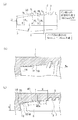
- FIG. 1 is a cross-sectional view showing a nose portion of a threaded joint for pipes according to an embodiment of the present invention.
- FIG. 2 is a cross-sectional view showing a conventional threaded joint for pipes.
- FIG. 3 is an enlarged cross-sectional view showing the vicinity of the pin nose in FIG.
- FIG. 4 is an enlarged cross-sectional view showing a threaded portion in FIG.
- FIG. 5 is a cross-sectional view showing definitions of screw gaps, load flank angles, and stub flank angles.
- FIG. 6 is a chart showing a load history in the leak test simulation.
- the outer peripheral surface of the nose portion of the pin member has a surface shape that forms an outwardly convex curve in the axial sectional view of the pin member.
- the inner peripheral surface of the box member opposed to the outer peripheral surface of the nose portion of the pin member has a tapered surface shape that intersects with the convex curve of the pin member at two points in an axial sectional view of the box member.
- a metal touch seal portion is formed by an outer peripheral surface of the nose portion of the pin member and an inner peripheral surface (hereinafter also referred to as a tapered surface) of the box member facing the outer peripheral surface of the nose portion, and the pin member of the seal portion Each interface on the side and the box member side becomes a sealing surface of the same member.
- the convex curve of the pin member is a composite R curve in which a plurality of arcs having different radii of curvature R are sequentially connected to the generatrix of the cylindrical portion adjacent to the male screw portion.
- the radius of curvature R of the arc increases as the distance from the male screw portion increases.
- the curve shape is such that the tangent line at the connection point of the arc coincides with that of the connection partner arc.
- the pin member It has been found that it is difficult to ensure sufficient sealing performance due to insufficient rigidity. As a result of further studies, it has been found that by setting the length of the nose portion to 5 mm or more and less than 20 mm, sufficient characteristics can be realized even if the outer diameter of the raw tube portion is 168.3 mm or less.
- FIG. 1 is a cross-sectional view showing a nose portion of a threaded joint for pipes according to an embodiment of the present invention.
- (A) shows the pin member 3,
- (b) shows the box member 1, and
- (c) shows a state where the pin member 3 and the box member 1 are coupled.
- the pin member 3 is provided at the end of the pipe, and includes a male screw part 7, a nose part 8 connected to the pipe end side from the male screw part 7, and a torque shoulder part 12 provided at the tip of the nose part 8.
- Have The outer diameter of the raw tube portion of the pin member 3 is 168.3 mm or less. Further, the outer diameter of the raw pipe portion of the pin member is preferably 60.3 mm or more which is usually used for OCTG, riser pipe and line pipe.
- the box member 1 includes a female screw portion 5 screwed to the male screw portion 7 of the pin member 3, and an outer peripheral surface (nose portion) of the nose portion 8 in a coupled state of the pin member 3 and the box member 1 by the screw coupling. It has a tapered surface 20 that is the inner peripheral surface of the box member 1 that faces the outer peripheral surface 30), and a shoulder portion 14 that comes into contact with the shoulder portion 12.
- the outer peripheral surface 30 of the nose portion has an outwardly convex curve in the axial sectional view of the pin member 3.
- the inner peripheral surface of the box member 1 facing the outer peripheral surface 30 of the nose portion is a tapered surface 20 (conical surface) having a constant inclination angle (referred to as a taper angle) ⁇ with respect to the axial direction of the threaded joint.
- the taper angle ⁇ is set so that the convex curve and the generatrix of the taper surface 20 intersect at two points in an axial cross-sectional view of the threaded joint in the virtual non-interference coupling state between the pin member 3 and the box member 1.
- the seal portion 40 is formed in a range (interference area 40a) sandwiched between the two intersections.
- the convex curve formed on the outer peripheral surface 30 of the nose portion will be described using the case of a composite R curve with three arcs shown in FIG.
- This curve, composite obtained by sequentially connecting the circular arc N 1, N 2, N 3 having a curvature radius R 1, R 2, R 3 of different line segment N 0 is a generating line of the cylindrical portion adjacent to the male screw portion 7 R curve N.
- the composite R curve N has a curved shape in which the radius of curvature of the arc increases with distance from the male screw portion 7, that is, R 1 ⁇ R 2 ⁇ R 3 .
- the thickness (shoulder thickness) t of the shoulder portion 12 at the tip of the pin nose 8 can be increased.
- the convex curve is a single R curve M (a single arc having a radius of curvature R) and the interference area of the seal portion is equivalent to the interference area 40a of the seal portion 40 of the composite R curve N is shown in FIG. Indicated by a broken line in (c).
- the shoulder thickness is smaller in the single R curve M than in the complex R curve N.
- the pin nose 8 has insufficient rigidity, and the contact surface pressure of the seal portion 40 cannot be ensured properly.
- the shoulder thickness is to be secured with a single R curve, the position of the seal portion 40 is moved away from the male screw portion 7, which is not preferable from the viewpoint of securing external pressure resistance and tensile resistance.
- the composite R curve N has a curved shape in which the tangent line at the connection point of the arc coincides with that of the connection partner arc.
- the tangents of the two arcs to be connected are made coincident with each other at the connection point between the arcs N 1 and N 2 and the connection point between the arcs N 2 and N 3 . Therefore, the convex curve has a continuous curve shape with no inflection point on the curve, and unauthorized deformation of the nose portion is suppressed.
- the two arcs to be connected may be directly connected or may not be directly connected. When not directly connected, it is preferable to sequentially join via a line segment having a length of 2.5 mm or less.
- the length of the arc having a sufficiently large line segment or radius is preferably 2.5 mm or less.
- angles ⁇ 1 , ⁇ 2 , and ⁇ 3 formed by the arcs N 1 , N 2 , and N 3 are larger as the arc is closer to the male screw portion 7, that is, ⁇ 1 > ⁇ 2 > ⁇ 3. It is preferable that Otherwise, within the length of the nose portion 8 of the limited pin member 3 (the pin nose length L in FIG. 1 (a)) or the length of the limited interference zone 40a (referred to as the seal contact length). It becomes difficult to design a composite R curve.
- a connecting point of the arc in the composite R curve for example, a connecting point of the arcs N 1 and N 2 or a connecting point of the arcs N 2 and N 3 is selected from the tapered surface 20 of the box member 1. It is preferable to coincide with a contact start point that means a point to be contacted first.
- the contact surface pressure distribution of the seal portion has a region where R is large, the surface pressure is low, and the contact length is long. A part having a high contact pressure and a short contact length can be formed, and a leak path is difficult to be formed, and the ultimate sealing performance is improved.
- the inclination of the tangent line at the connection point of the arc is preferably made smaller than the inclination of the tapered surface of the box member in a range up to 0.5 degrees.
- deformation that causes the tip of the pin to taper due to radial interference between the pin and the box occurs, and the tangential slope of the pin surface at the time of tightening is greater than the design value. .
- the contact start point is less than or equal to 0.7 L (L is the pin nose length as described above) from the viewpoint of separating the seal portion from the tip of the nose and the distance x from the tip of the male screw portion (see FIG. 1C). It is good to put in the position. Furthermore, when the distance from the tip of the male screw portion at the contact start point is less than 0.2 L, interference between the seal portion and the screw portion is likely to occur during tightening, so 0.2 L or more is preferable. Furthermore, 0.3L or more is good for safety.
- the pin nose length L needs to be 5 mm or more and less than 20 mm. If L is less than 5 mm, it is difficult to ensure the length of the seal portion in the tube axis direction. On the other hand, when the outer diameter of the raw tube portion of the pin member is 168.3 mm or less, the raw tube thickness is small and the shoulder thickness is small. Therefore, when the pin nose length L is 20 mm or more, the rigidity of the pin nose 8 is insufficient, and the external pressure resistance Performance decreases. In the present invention, by limiting the pin nose length L to 5 mm or more and less than 20 mm, the seal portion is sufficiently separated from the tip of the pin nose while ensuring rigidity. As a result, the elastic deformation within the separation distance range can greatly reduce damage to the seal portion, which is effective in stabilizing the sealing performance.
- the taper angle ⁇ of the taper surface 20 of the box member 1 is preferably within 10 degrees. By making the taper angle ⁇ within 10 degrees, more preferably within 5 degrees, the radial seal method can be suitably realized, and the tightening torque dependency of the sealing performance becomes relatively low.
- the seal interference amount S (see FIG. 1 (c)) can be relatively small as a radial seal method, and the goling risk is small.
- two or more types of R in the composite R curve are preferably 1 inch or less for a relatively small R, 2 inches or more for a relatively large R, and 3 inches or more for a larger R.
- at least one of a plurality of Rs in the composite R curve is 2 inches or more (more preferably 3 inches or more), and at least one R is less than 2 inches (more preferably 1 inch or less). Is preferred.
- the number of arcs in the composite R curve may be two, may be three illustrated in FIG. 1, or may be four or more. As the number of arcs increases, the seal contact length becomes larger and the sealing performance can be improved more easily. Therefore, the number of arcs should be designed according to the performance actually required for the threaded joint.
- the cross-sectional area of the pin member at the contact start point is 35% or more of the cross-sectional area of the main body of the pipe (the cross-sectional area of the unprocessed pin) at which the joint is formed at the tip.
- the cross-sectional area of the pin member at the contact start point is 40% or more of the cross-sectional area of the pipe body.
- the male screw portion and the female screw portion can be further sealed by defining one or more of the load flank angle, the stub flank angle, and the screw gap within a preferable range.
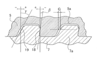
- the load flank angle is the load flank angle ⁇ shown in FIG. 5, that is, the angle ⁇ formed by the load flank surface 18 with respect to the joint axis orthogonal plane (meaning the plane orthogonal to the axial direction of the threaded joint, hereinafter the same).
- the stub flank angle is the stub flank angle ⁇ shown in FIG. 5, that is, the angle ⁇ formed by the stub flank surface 19 with respect to the joint axis orthogonal surface.
- the screw gap is the screw gap G shown in FIG. 5, that is, the gap G between the thread 7a of the male screw and the screw groove 5a of the female screw meshing with the screw thread 7a.
- the preferable range of the load flank angle ⁇ is -5 ° to 4 °, and the lower limit of the preferable range is determined from the viewpoint of galling resistance and tool life of the threaded portion, and the upper limit is determined from the viewpoint of bending resistance.
- the preferred range of the stub flank angle ⁇ is 0 ° to 30 °.
- the lower limit of the preferred range is determined from the viewpoint of galling resistance, tool life and tightening property of the threaded portion, and the upper limit is determined from the viewpoint of axial compression resistance. It was.
- the preferable range of the screw gap G is 0.01 to 0.1 mm.
- the lower limit of the preferable range is determined from the viewpoint of reducing the goring risk, and the upper limit is determined from the viewpoint of reducing the load on the pin tip during the axial compression load. It was.
- the screw gap G is preferably about 0.03 mm at least. Moreover, since it discovered that the screw gap G was about 0.045 mm and can exhibit sufficient performance effectively, it is good also as about 0.045 mm according to a condition.
- a preferable range of the screw gap G is 0.03 to 0.05 mm.
- the overall effect of improving the sealing performance is particularly the axial tension + internal pressure or This is remarkable under conditions where external pressure is applied.
- the shoulder angle of the shoulder portion (the angle formed by the end surface of the shoulder portion in the joint axis direction with respect to the joint axis orthogonal surface, and the pin outer peripheral side of the interface protruding from the pin inner peripheral side to the outer side in the joint axial direction)
- the positive angle is preferably 0 to 20 degrees. If the shoulder angle is less than 0 degrees, it is disadvantageous in terms of sealing performance and tightening characteristics, while if it exceeds 20 degrees, it is disadvantageous in that plastic deformation of the box shoulder part and local deformation of the seal part are likely to occur. Preferably it is 15 degrees or less. Furthermore, depending on the situation, 7 degrees or less is preferable.
- Tables 1 and 2 show the dimensional shapes and evaluation results of examples (invention examples) and comparative examples of the present invention.
- Each pin member was formed at the tip of a steel pipe having an outer diameter of 127.00 mm and a wall thickness of 9.19 mm.
- the screw was formed at 5 TPI (5 threads per inch).
- the pin nose length L was set to 20 mm or more, which is outside the scope of the present invention.
- a physical test was conducted by producing a plurality of samples having different seal interference amounts with a screw interference amount of 0.305 mm per diameter by a test method defined in ISO 13679: 2002. did. Further, a plurality of samples with the interference amount of the screw changed to 0.127 mm per diameter and the amount of interference of the seal were changed, and the tightening test was repeated 13 times. By these tests, the minimum seal interference amount that did not cause a leak in the physical test and the maximum seal interference amount that did not cause a goling during the 13 tightenings in the repeated tightening test can be obtained and set with the difference.
- the seal interference amount range The seal interference amount range.
- Table 1 shows the contact area pressure and goring index obtained by FEM calculation, and the maximum and minimum seal interference amounts obtained by actual physical tests and repeated tightening tests, together with the dimensions of each part of the threaded joint, for the inventive examples and comparative examples. Shown in Here, the amount of seal interference in Table 1 is a value per diameter, and is a value corresponding to the amount of seal interference S ⁇ 2 shown in FIG.
- the contact area pressure under the internal pressure condition in the FEM calculation is the minimum value in the vicinity of the load steps L3 and L18 (biaxial tensile stress + internal pressure) in the history of FIG. )showed that.
- This load point is not specified in ISO 13679, but the internal pressure + tensile condition is the most severe condition and may be required.
- the contact area pressure under the external pressure condition in the FEM calculation showed a minimum value in the vicinity of the load step L15 (biaxial tensile stress + external pressure) in the history of FIG. Table 1 shows the minimum value of the contact area pressure in each example as a relative minimum value.
- the relative minimum value was determined based on the minimum values of the internal pressure condition and the external pressure condition.
- the minimum values of L3 and L18 were expressed as ratios relative to the minimum value of 100 for all the examples of L3 and L18.
- the minimum value of L15 is expressed as a ratio with respect to the minimum value of 100 as the minimum value among all examples of L15.
- the judgment standard value was not suitable when the contact area pressure was 100 or less for the sealing property, and 100 or more was inappropriate for the goring index.
- the load step L18 after receiving the compression history once has a lower sealing performance than the load step L3, which is the same load point before receiving the compression history, and in particular Comparative Example 3 which does not have a sufficient shoulder thickness. There is a noticeable decrease in.
- the inventive examples showed good sealing properties at L18 after the compression history.
- the position in the joint axial direction showing the maximum value was different for each example.
- the maximum value of the Goring index of each example is displayed as a relative maximum value (the maximum maximum value is 100 among all examples, and the others are expressed as ratios thereto).
- Table 3 shows the evaluation results at other sizes.
- the target materials have an outer diameter of 139.70 mm, a wall thickness of 7.72 mm, and 5 TPI, and an outer diameter of 88.90 mm, a wall thickness of 10.92 mm, and 6 TPI.
- the examples of the present invention showed excellent sealing performance after compression history and excellent galling resistance during tightening.
Abstract
Description
(1)雄ねじ部と、該雄ねじ部より管端側に延在するノーズ部と、該ノーズ部の先端に設けられたショルダ部とを有するピン部材と、
前記雄ねじ部とねじ結合される雌ねじ部と、前記ピン部材のノーズ部外周面に相対する内周面と、前記ピン部材のショルダ部に当接するショルダ部とを有するボックス部材とを具備し、
前記ねじ結合により前記ピン部材とボックス部材とが結合されてピン部材のノーズ部外周面とボックス部材の前記内周面とがメタル‐メタル接触しその接触界面がシール面になる管用ねじ継手であって、
前記ピン部材のノーズ部外周面は、ピン部材の軸方向断面視で外側に凸状の曲線をなし、該凸状の曲線は、雄ねじ部に隣接する円筒形状部の母線に相異なる曲率半径Rを有する外側に凸状の複数の円弧を順次接続してなる複合R曲線を、雄ねじ部から遠ざかるにつれて円弧の曲率半径Rが大きくなり、かつ、円弧の接続点上の接線が接続相手の円弧のそれと一致するような曲線形状としたものであり、
前記ボックス部材の前記内周面は、ピン部材との結合時にピン部材のノーズ部外周面と干渉するテーパ面とし、
前記ピン部材の素管部外径を168.3mm以下とし、前記ノーズ部の長さを5mm以上20mm未満としたことを特徴とする、管用ねじ継手。
(2)前記複合R曲線内の各円弧がなす角度は、前記雄ねじ部に近い円弧のものほど大きいことを特徴とする前記(1)に記載の管用ねじ継手。
(3)前記複合R曲線内の前記接続点のいずれかが前記テーパ面との接触開始点になることを特徴とする前記(1)又は(2)に記載の管用ねじ継手。
(4)前記テーパ面は、継手の軸方向となす角度が10度以内であることを特徴とする前記(1)~(3)のいずれかに記載の管用ねじ継手。
(5)前記雄ねじ部と前記雌ねじ部とは、スタブフランク角度が0度~30度の範囲内であることを特徴とする前記(1)~(4)のいずれかに記載の管用ねじ継手。
(6)前記雄ねじ部と前記雌ねじ部とは、ロードフランク角度が-5度~4度の範囲内であることを特徴とする前記(1)~(5)のいずれかに記載の管用ねじ継手。
(7)前記ショルダ部のショルダ角度が0度~20度の範囲内であることを特徴とする前記(1)~(6)のいずれかに記載の管用ねじ継手。
(8)前記雄ねじ部と前記雌ねじ部とは、ねじ隙間が0.01~0.1mmの範囲内であることを特徴とする前記(1)~(7)のいずれかに記載の管用ねじ継手。
(9)前記(1)~(8)のいずれかにおいて、雄ねじ部に隣接する円筒形状部の母線に相異なる曲率半径Rを有する複数の円弧を順次接続した複合R曲線に代えて、雄ねじ部に隣接する円筒形状部の母線に相異なる曲率半径Rを有する複数の円弧を直接もしくは長さ2.5mm以下の線分を介して順次接続した複合R曲線としたことを特徴とする管用ねじ継手。
(10)前記(1)~(8)のいずれかにおいて、雄ねじ部に隣接する円筒形状部の母線に相異なる曲率半径Rを有する複数の円弧を順次接続した複合R曲線に代えて、雄ねじ部に隣接する円筒形状部の母線に相異なる曲率半径Rを有する複数の円弧を長さ2.5mm以下で、半径が250mm以上かつ隣接する円弧の半径の3倍以上となる円弧を介して順次接続した複合R曲線としたことを特徴とする管用ねじ継手。 In order to find out the means for solving the above-mentioned problems, the inventors have made extensive studies based on the threaded joint for pipes described in Patent Document 7 and have come to achieve the present invention having the following gist. That is, the present invention is as follows.
(1) a pin member having a male screw portion, a nose portion extending from the male screw portion toward the tube end side, and a shoulder portion provided at the tip of the nose portion;
A box member having a female screw portion that is screw-coupled to the male screw portion, an inner peripheral surface that faces the outer peripheral surface of the nose portion of the pin member, and a shoulder portion that contacts the shoulder portion of the pin member;
A screw joint for pipes in which the pin member and the box member are connected by the screw connection so that the outer peripheral surface of the nose portion of the pin member and the inner peripheral surface of the box member are in metal-metal contact, and the contact interface is a seal surface. And
The outer peripheral surface of the nose portion of the pin member has an outwardly convex curve in the axial sectional view of the pin member, and the convex curve has a radius of curvature R different from the generatrix of the cylindrical portion adjacent to the external thread portion. The radius of curvature R of the arc increases as the distance from the male thread portion increases, and the tangent line on the connection point of the arc is the connection partner's arc. It has a curved shape that matches it,
The inner peripheral surface of the box member is a tapered surface that interferes with the outer peripheral surface of the nose portion of the pin member when coupled with the pin member,
A threaded joint for pipes, characterized in that the outer diameter of the raw pipe portion of the pin member is 168.3 mm or less, and the length of the nose portion is 5 mm or more and less than 20 mm.
(2) The threaded joint for pipes according to (1), wherein an angle formed by each arc in the composite R curve is larger as the arc is closer to the male thread portion.
(3) The threaded joint for pipes according to (1) or (2), wherein any one of the connection points in the composite R curve is a contact start point with the tapered surface.
(4) The threaded joint for pipes according to any one of (1) to (3), wherein an angle formed between the tapered surface and the axial direction of the joint is within 10 degrees.
(5) The threaded joint for pipes according to any one of (1) to (4), wherein the male threaded portion and the female threaded portion have a stub flank angle in a range of 0 degrees to 30 degrees.
(6) The threaded joint for pipes according to any one of (1) to (5), wherein the male thread part and the female thread part have a load flank angle within a range of −5 degrees to 4 degrees. .
(7) The threaded joint for pipes according to any one of (1) to (6), wherein a shoulder angle of the shoulder portion is within a range of 0 degrees to 20 degrees.
(8) The threaded joint for pipes according to any one of (1) to (7) above, wherein the male screw part and the female screw part have a screw gap in the range of 0.01 to 0.1 mm. .
(9) In any one of the above (1) to (8), instead of the composite R curve in which a plurality of arcs having different curvature radii R are sequentially connected to the generatrix of the cylindrical portion adjacent to the male screw portion, the male screw portion Threaded joint for pipes characterized in that it is a composite R curve in which a plurality of circular arcs having different curvature radii R are sequentially connected to a generatrix of a cylindrical portion adjacent to each other directly or via a line segment having a length of 2.5 mm or less .
(10) In any one of the above (1) to (8), instead of the composite R curve in which a plurality of arcs having different curvature radii R are sequentially connected to the generatrix of the cylindrical portion adjacent to the male screw portion, the male screw portion A plurality of circular arcs having different radii of curvature R are sequentially connected to the generatrix of the cylindrical portion adjacent to each other via an arc having a length of 2.5 mm or less and a radius of 250 mm or more and three or more times the radius of the adjacent arc. A threaded joint for pipes, characterized in that it is a composite R curve.
(条件1)ピン部材のノーズ部外周面が、ピン部材の軸方向断面視で外側に凸状の曲線をなす面形状とされる。
(条件2)このピン部材のノーズ部外周面と相対するボックス部材の内周面が、ボックス部材の軸方向断面視でピン部材の凸状の曲線と二点で交わるテーパ面形状とされる。
(条件3)前記ピン部材のノーズ部外周面とこのノーズ部外周面に相対するボックス部材の内周面(以下テーパ面ともいう)とでメタルタッチシール部が形成され、該シール部のピン部材側、ボックス部材側の各界面がそれぞれ同部材のシール面となる。
(要件1)ピン部材の凸状の曲線は、雄ねじ部に隣接する円筒形状部の母線に相異なる曲率半径Rを有する複数の円弧を順次接続した複合R曲線とする。
(要件2)雄ねじ部から遠ざかるにつれて前記円弧の曲率半径Rが大きくなる。
(要件3)円弧の接続点上の接線が接続相手の円弧のそれと一致するような曲線形状とする。 As a result, when the following conditions 1 to 3 are satisfied, the following requirements 1 to 3 are satisfied, so that the seal portion can be separated from the nose tip without reducing the thickness of the pin nose tip. It came to.
(Condition 1) The outer peripheral surface of the nose portion of the pin member has a surface shape that forms an outwardly convex curve in the axial sectional view of the pin member.
(Condition 2) The inner peripheral surface of the box member opposed to the outer peripheral surface of the nose portion of the pin member has a tapered surface shape that intersects with the convex curve of the pin member at two points in an axial sectional view of the box member.
(Condition 3) A metal touch seal portion is formed by an outer peripheral surface of the nose portion of the pin member and an inner peripheral surface (hereinafter also referred to as a tapered surface) of the box member facing the outer peripheral surface of the nose portion, and the pin member of the seal portion Each interface on the side and the box member side becomes a sealing surface of the same member.
(Requirement 1) The convex curve of the pin member is a composite R curve in which a plurality of arcs having different radii of curvature R are sequentially connected to the generatrix of the cylindrical portion adjacent to the male screw portion.
(Requirement 2) The radius of curvature R of the arc increases as the distance from the male screw portion increases.
(Requirement 3) The curve shape is such that the tangent line at the connection point of the arc coincides with that of the connection partner arc.


3 ピン(ピン部材)
5 雌ねじ(雌ねじ部)
5a 雌ねじのねじ溝
7 雄ねじ(雄ねじ部)
7a 雄ねじのねじ山
8 ノーズ部(ピンノーズ)
11、13、40 シール部(詳しくはメタルタッチシール部)
12、14 ショルダ部(詳しくはトルクショルダ部)
18 ロードフランク面
19 スタブフランク面
20 ピン部材のノーズ部外周面に相対するボックス部材の内周面(テーパ面)
30 ピン部材のノーズ部外周面(ピンノーズ外周面)
40a 干渉域 1 Box material
3 Pin (Pin material)
5 Female thread (Female thread)
5a Female thread groove
7 Male thread (Male thread)
7a Male thread thread
8 Nose (pin nose)
11, 13, 40 Seal (Details are metal touch seal)
12, 14 Shoulder part (For details, torque shoulder part)
18 Road flank surface
19 Stub flank face
20 Inner peripheral surface (tapered surface) of the box member facing the outer peripheral surface of the nose part of the pin member
30 Pin member nose outer peripheral surface (pin nose outer peripheral surface)
40a Interference zone
Claims (10)
- 雄ねじ部と、該雄ねじ部より管端側に延在するノーズ部と、該ノーズ部の先端に設けられたショルダ部とを有するピン部材と、
前記雄ねじ部とねじ結合される雌ねじ部と、前記ピン部材のノーズ部外周面に相対する内周面と、前記ピン部材のショルダ部に当接するショルダ部とを有するボックス部材と、を具備し、
前記ねじ結合により前記ピン部材とボックス部材とが結合されてピン部材のノーズ部外周面とボックス部材の前記内周面とがメタル-メタル接触しその接触界面がシール面になる管用ねじ継手であって、
前記ピン部材のノーズ部外周面は、ピン部材の軸方向断面視で外側に凸状の曲線をなし、該凸状の曲線は、雄ねじ部に隣接する円筒形状部の母線に相異なる曲率半径Rを有する外側に凸状の複数の円弧を順次接続してなる複合R曲線を、雄ねじ部から遠ざかるにつれて円弧の曲率半径Rが大きくなり、かつ、円弧の接続点上の接線が接続相手の円弧のそれと一致するような曲線形状としたものであり、
前記ボックス部材の前記内周面は、ピン部材との結合時にピン部材のノーズ部外周面と干渉するテーパ面とし、
前記ピン部材の素管部外径を168.3mm以下とし、前記ノーズ部の長さを5mm以上20mm未満としたことを特徴とする、管用ねじ継手。 A pin member having a male screw part, a nose part extending from the male screw part to the tube end side, and a shoulder part provided at the tip of the nose part;
A female screw part that is screw-coupled to the male screw part, an inner peripheral surface that faces the outer peripheral surface of the nose part of the pin member, and a box member that has a shoulder part that contacts the shoulder part of the pin member,
A screw joint for pipes in which the pin member and the box member are connected by the screw connection, and the outer peripheral surface of the nose portion of the pin member and the inner peripheral surface of the box member are in metal-metal contact, and the contact interface is a seal surface. And
The outer peripheral surface of the nose portion of the pin member has an outwardly convex curve in the axial sectional view of the pin member, and the convex curve has a radius of curvature R different from the generatrix of the cylindrical portion adjacent to the external thread portion. The radius of curvature R of the arc increases as the distance from the male thread portion increases, and the tangent line on the connection point of the arc is the connection partner's arc. It has a curved shape that matches it,
The inner peripheral surface of the box member is a tapered surface that interferes with the outer peripheral surface of the nose portion of the pin member when coupled with the pin member,
A threaded joint for pipes, characterized in that the outer diameter of the raw pipe portion of the pin member is 168.3 mm or less, and the length of the nose portion is 5 mm or more and less than 20 mm. - 前記複合R曲線内の各円弧がなす角度は、前記雄ねじ部に近い円弧のものほど大きいことを特徴とする請求項1に記載の管用ねじ継手。 2. The threaded joint for pipes according to claim 1, wherein an angle formed by each arc in the composite R curve is larger as the arc is closer to the male thread portion.
- 前記複合R曲線内の前記接続点のいずれかが前記テーパ面との接触開始点になることを特徴とする請求項1又は2に記載の管用ねじ継手。 3. The threaded joint for pipes according to claim 1 or 2, wherein any one of the connection points in the composite R curve is a contact start point with the tapered surface.
- 前記テーパ面は、継手の軸方向となす角度が10度以内であることを特徴とする請求項1~3のいずれかに記載の管用ねじ継手。 The threaded joint for pipes according to any one of claims 1 to 3, wherein the tapered surface has an angle of 10 degrees or less with an axial direction of the joint.
- 前記雄ねじ部と前記雌ねじ部とは、スタブフランク角度が0度~30度の範囲内であることを特徴とする前記請求項1~4のいずれかに記載の管用ねじ継手。 5. The threaded joint for pipes according to claim 1, wherein the male thread part and the female thread part have a stub flank angle in a range of 0 degrees to 30 degrees.
- 前記雄ねじ部と前記雌ねじ部とは、ロードフランク角度が-5度~4度の範囲内であることを特徴とする請求項1~5のいずれかに記載の管用ねじ継手。 6. The threaded joint for pipes according to any one of claims 1 to 5, wherein a load flank angle of the male thread part and the female thread part is within a range of -5 degrees to 4 degrees.
- 前記ショルダ部のショルダ角度が0度~20度の範囲内であることを特徴とする請求項1~6のいずれかに記載の管用ねじ継手。 The threaded joint for pipes according to any one of claims 1 to 6, wherein a shoulder angle of the shoulder portion is in a range of 0 degrees to 20 degrees.
- 前記雄ねじ部と前記雌ねじ部とは、ねじ隙間が0.01~0.1mmの範囲内であることを特徴とする請求項1~7のいずれかに記載の管用ねじ継手。 The threaded joint for pipes according to any one of claims 1 to 7, wherein a screw gap between the male screw portion and the female screw portion is in a range of 0.01 to 0.1 mm.
- 請求項1~8のいずれかにおいて、雄ねじ部に隣接する円筒形状部の母線に相異なる曲率半径Rを有する複数の円弧を順次接続した複合R曲線に代えて、雄ねじ部に隣接する円筒形状部の母線に相異なる曲率半径Rを有する複数の円弧を直接もしくは長さ2.5mm以下の線分を介して順次接続した複合R曲線としたことを特徴とする管用ねじ継手。 9. The cylindrical portion adjacent to the male screw portion according to claim 1, instead of the composite R curve in which a plurality of arcs having different radii of curvature R are sequentially connected to the generatrix of the cylindrical portion adjacent to the male screw portion. A threaded joint for pipes comprising a composite R curve in which a plurality of circular arcs having different radii of curvature R are connected directly to each other through a straight line segment having a length of 2.5 mm or less.
- 請求項1~8のいずれかにおいて、雄ねじ部に隣接する円筒形状部の母線に相異なる曲率半径Rを有する複数の円弧を順次接続した複合R曲線に代えて、雄ねじ部に隣接する円筒形状部の母線に相異なる曲率半径Rを有する複数の円弧を長さ2.5mm以下で、半径が250mm以上かつ隣接する円弧の半径の3倍以上となる円弧を介して順次接続した複合R曲線としたことを特徴とする管用ねじ継手。 9. The cylindrical portion adjacent to the male screw portion according to claim 1, instead of the composite R curve in which a plurality of arcs having different radii of curvature R are sequentially connected to the generatrix of the cylindrical portion adjacent to the male screw portion. A plurality of circular arcs having different curvature radii R to the generatrix are combined R curves sequentially connected via an arc having a length of 2.5 mm or less, a radius of 250 mm or more, and a radius of 3 times or more of adjacent arcs. A threaded joint for pipes.
Priority Applications (5)
| Application Number | Priority Date | Filing Date | Title |
|---|---|---|---|
| BR112017014103-5A BR112017014103B1 (en) | 2015-01-15 | 2015-11-24 | SCREW JOINT FOR TUBE |
| MX2017009201A MX2017009201A (en) | 2015-01-15 | 2015-11-24 | Threaded pipe joint. |
| EP15877747.4A EP3246611B1 (en) | 2015-01-15 | 2015-11-24 | Screw joint for pipe |
| JP2016512141A JP6103137B2 (en) | 2015-01-15 | 2015-11-24 | Threaded joints for pipes |
| US15/542,137 US20180258709A1 (en) | 2015-01-15 | 2015-11-24 | Screw joint for pipe (as amended) |
Applications Claiming Priority (2)
| Application Number | Priority Date | Filing Date | Title |
|---|---|---|---|
| JP2015005676 | 2015-01-15 | ||
| JP2015-005676 | 2015-03-17 |
Publications (1)
| Publication Number | Publication Date |
|---|---|
| WO2016113790A1 true WO2016113790A1 (en) | 2016-07-21 |
Family
ID=56405360
Family Applications (1)
| Application Number | Title | Priority Date | Filing Date |
|---|---|---|---|
| PCT/JP2015/005830 WO2016113790A1 (en) | 2015-01-15 | 2015-11-24 | Threaded pipe joint |
Country Status (7)
| Country | Link |
|---|---|
| US (1) | US20180258709A1 (en) |
| EP (1) | EP3246611B1 (en) |
| JP (1) | JP6103137B2 (en) |
| AR (1) | AR103409A1 (en) |
| BR (1) | BR112017014103B1 (en) |
| MX (1) | MX2017009201A (en) |
| WO (1) | WO2016113790A1 (en) |
Cited By (1)
| Publication number | Priority date | Publication date | Assignee | Title |
|---|---|---|---|---|
| JPWO2021171826A1 (en) * | 2020-02-26 | 2021-09-02 |
Families Citing this family (3)
| Publication number | Priority date | Publication date | Assignee | Title |
|---|---|---|---|---|
| EA037807B1 (en) * | 2017-05-22 | 2021-05-24 | Ниппон Стил Корпорейшн | Threaded connection for steel pipes |
| PT3536894T (en) * | 2018-03-09 | 2020-11-19 | Sandvik Mining And Construction Tools Ab | Coupling for connecting downhole tubulars |
| US11624460B2 (en) * | 2018-10-02 | 2023-04-11 | Nippon Steel Corporation | Threaded connection for steel pipe |
Citations (7)
| Publication number | Priority date | Publication date | Assignee | Title |
|---|---|---|---|---|
| JPH08121660A (en) * | 1994-10-19 | 1996-05-17 | Sumitomo Metal Ind Ltd | Threaded joint for oil well pipe |
| JPH1096489A (en) * | 1996-09-24 | 1998-04-14 | Sumitomo Metal Ind Ltd | Screw joint for oil well pipe excellent in external pressure resistance |
| JP2005351324A (en) * | 2004-06-09 | 2005-12-22 | Metal One Corp | Screw joint for oil well pipe |
| JP4535064B2 (en) * | 2003-06-06 | 2010-09-01 | 住友金属工業株式会社 | Threaded joints for steel pipes |
| JP4930647B1 (en) * | 2010-06-30 | 2012-05-16 | Jfeスチール株式会社 | Threaded joints for pipes |
| WO2012128015A1 (en) * | 2011-03-22 | 2012-09-27 | Jfeスチール株式会社 | Screw joint for steel piping |
| WO2014006866A1 (en) * | 2012-07-04 | 2014-01-09 | Jfeスチール株式会社 | Threaded pipe joint |
Family Cites Families (4)
| Publication number | Priority date | Publication date | Assignee | Title |
|---|---|---|---|---|
| JPS4930647B1 (en) * | 1968-12-30 | 1974-08-15 | ||
| US4692988A (en) * | 1986-08-19 | 1987-09-15 | Nowsco Well Service (U.K.) Limited | Screw thread protection |
| JP3876656B2 (en) * | 2001-07-13 | 2007-02-07 | 住友金属工業株式会社 | Threaded joints for pipes |
| JP5803953B2 (en) * | 2013-02-18 | 2015-11-04 | Jfeスチール株式会社 | Threaded joint for pipe connection |
-
2015
- 2015-11-24 WO PCT/JP2015/005830 patent/WO2016113790A1/en active Application Filing
- 2015-11-24 BR BR112017014103-5A patent/BR112017014103B1/en active IP Right Grant
- 2015-11-24 EP EP15877747.4A patent/EP3246611B1/en active Active
- 2015-11-24 MX MX2017009201A patent/MX2017009201A/en active IP Right Grant
- 2015-11-24 US US15/542,137 patent/US20180258709A1/en not_active Abandoned
- 2015-11-24 JP JP2016512141A patent/JP6103137B2/en active Active
-
2016
- 2016-01-14 AR ARP160100080A patent/AR103409A1/en active IP Right Grant
Patent Citations (7)
| Publication number | Priority date | Publication date | Assignee | Title |
|---|---|---|---|---|
| JPH08121660A (en) * | 1994-10-19 | 1996-05-17 | Sumitomo Metal Ind Ltd | Threaded joint for oil well pipe |
| JPH1096489A (en) * | 1996-09-24 | 1998-04-14 | Sumitomo Metal Ind Ltd | Screw joint for oil well pipe excellent in external pressure resistance |
| JP4535064B2 (en) * | 2003-06-06 | 2010-09-01 | 住友金属工業株式会社 | Threaded joints for steel pipes |
| JP2005351324A (en) * | 2004-06-09 | 2005-12-22 | Metal One Corp | Screw joint for oil well pipe |
| JP4930647B1 (en) * | 2010-06-30 | 2012-05-16 | Jfeスチール株式会社 | Threaded joints for pipes |
| WO2012128015A1 (en) * | 2011-03-22 | 2012-09-27 | Jfeスチール株式会社 | Screw joint for steel piping |
| WO2014006866A1 (en) * | 2012-07-04 | 2014-01-09 | Jfeスチール株式会社 | Threaded pipe joint |
Cited By (3)
| Publication number | Priority date | Publication date | Assignee | Title |
|---|---|---|---|---|
| JPWO2021171826A1 (en) * | 2020-02-26 | 2021-09-02 | ||
| WO2021171826A1 (en) * | 2020-02-26 | 2021-09-02 | Jfeスチール株式会社 | Seamless tube and method for manufacturing same |
| JP7156514B2 (en) | 2020-02-26 | 2022-10-19 | Jfeスチール株式会社 | Seamless pipe and its manufacturing method |
Also Published As
| Publication number | Publication date |
|---|---|
| EP3246611A4 (en) | 2018-01-24 |
| MX2017009201A (en) | 2018-04-24 |
| US20180258709A1 (en) | 2018-09-13 |
| BR112017014103B1 (en) | 2021-11-23 |
| BR112017014103A2 (en) | 2018-01-09 |
| EP3246611A1 (en) | 2017-11-22 |
| EP3246611B1 (en) | 2019-10-02 |
| JPWO2016113790A1 (en) | 2017-04-27 |
| JP6103137B2 (en) | 2017-03-29 |
| AR103409A1 (en) | 2017-05-10 |
Similar Documents
| Publication | Publication Date | Title |
|---|---|---|
| JP4930647B1 (en) | Threaded joints for pipes | |
| JP5660308B2 (en) | Threaded joints for steel pipes | |
| JP5849749B2 (en) | Threaded joints for pipes | |
| JP6187724B1 (en) | Threaded joint for oil well pipe | |
| JP7120179B2 (en) | Threaded joints for oil well pipes | |
| WO2015104739A1 (en) | Threaded joint for ultra thick oil well pipe | |
| JP6103137B2 (en) | Threaded joints for pipes | |
| JP5978953B2 (en) | Threaded joints for pipes | |
| WO2014006866A1 (en) | Threaded pipe joint | |
| JP5673089B2 (en) | Threaded joints for steel pipes | |
| JP6020087B2 (en) | Threaded joints for pipes | |
| JP5704191B2 (en) | Threaded joint for oil well pipes with excellent seizure resistance | |
| JP5776222B2 (en) | Threaded joints for steel pipes | |
| JP5906588B2 (en) | Manufacturing method of threaded joint for steel pipe | |
| WO2020075342A1 (en) | Threaded joint | |
| JP6051811B2 (en) | Threaded joints for pipes | |
| WO2014125545A1 (en) | Threaded joint for pipe | |
| JP5673090B2 (en) | Threaded joints for steel pipes | |
| JP2013029177A (en) | Steel pipe screw joint | |
| JP2013029174A (en) | Steel pipe screw joint | |
| JP5906587B2 (en) | Manufacturing method of threaded joint for steel pipe |
Legal Events
| Date | Code | Title | Description |
|---|---|---|---|
| ENP | Entry into the national phase |
Ref document number: 2016512141 Country of ref document: JP Kind code of ref document: A |
|
| 121 | Ep: the epo has been informed by wipo that ep was designated in this application |
Ref document number: 15877747 Country of ref document: EP Kind code of ref document: A1 |
|
| REEP | Request for entry into the european phase |
Ref document number: 2015877747 Country of ref document: EP |
|
| WWE | Wipo information: entry into national phase |
Ref document number: 15542137 Country of ref document: US |
|
| REG | Reference to national code |
Ref country code: BR Ref legal event code: B01A Ref document number: 112017014103 Country of ref document: BR |
|
| WWE | Wipo information: entry into national phase |
Ref document number: MX/A/2017/009201 Country of ref document: MX |
|
| NENP | Non-entry into the national phase |
Ref country code: DE |
|
| ENP | Entry into the national phase |
Ref document number: 112017014103 Country of ref document: BR Kind code of ref document: A2 Effective date: 20170629 |